JP6791616B2 - Self-driving vehicle system - Google Patents
Self-driving vehicle system Download PDFInfo
- Publication number
- JP6791616B2 JP6791616B2 JP2015090260A JP2015090260A JP6791616B2 JP 6791616 B2 JP6791616 B2 JP 6791616B2 JP 2015090260 A JP2015090260 A JP 2015090260A JP 2015090260 A JP2015090260 A JP 2015090260A JP 6791616 B2 JP6791616 B2 JP 6791616B2
- Authority
- JP
- Japan
- Prior art keywords
- vehicle
- control
- target
- vehicle state
- travel plan
- Prior art date
- Legal status (The legal status is an assumption and is not a legal conclusion. Google has not performed a legal analysis and makes no representation as to the accuracy of the status listed.)
- Active
Links
- 230000002093 peripheral effect Effects 0.000 claims description 111
- 238000013459 approach Methods 0.000 claims description 50
- 230000001133 acceleration Effects 0.000 description 51
- 230000008859 change Effects 0.000 description 26
- 238000010586 diagram Methods 0.000 description 20
- 238000012545 processing Methods 0.000 description 20
- 238000001514 detection method Methods 0.000 description 19
- 238000000034 method Methods 0.000 description 18
- 230000008569 process Effects 0.000 description 16
- 238000012986 modification Methods 0.000 description 12
- 230000004048 modification Effects 0.000 description 12
- 238000003384 imaging method Methods 0.000 description 6
- 238000004891 communication Methods 0.000 description 3
- 230000004913 activation Effects 0.000 description 2
- 230000000694 effects Effects 0.000 description 2
- 230000006870 function Effects 0.000 description 2
- 230000010365 information processing Effects 0.000 description 2
- 230000004043 responsiveness Effects 0.000 description 2
- 238000005516 engineering process Methods 0.000 description 1
- 230000005484 gravity Effects 0.000 description 1
- 230000004807 localization Effects 0.000 description 1
- 238000013507 mapping Methods 0.000 description 1
- 238000005259 measurement Methods 0.000 description 1
- 239000013589 supplement Substances 0.000 description 1
Images


Classifications
-
- G—PHYSICS
- G08—SIGNALLING
- G08G—TRAFFIC CONTROL SYSTEMS
- G08G1/00—Traffic control systems for road vehicles
- G08G1/16—Anti-collision systems
-
- B—PERFORMING OPERATIONS; TRANSPORTING
- B62—LAND VEHICLES FOR TRAVELLING OTHERWISE THAN ON RAILS
- B62D—MOTOR VEHICLES; TRAILERS
- B62D1/00—Steering controls, i.e. means for initiating a change of direction of the vehicle
- B62D1/24—Steering controls, i.e. means for initiating a change of direction of the vehicle not vehicle-mounted
- B62D1/28—Steering controls, i.e. means for initiating a change of direction of the vehicle not vehicle-mounted non-mechanical, e.g. following a line or other known markers
-
- B—PERFORMING OPERATIONS; TRANSPORTING
- B62—LAND VEHICLES FOR TRAVELLING OTHERWISE THAN ON RAILS
- B62D—MOTOR VEHICLES; TRAILERS
- B62D15/00—Steering not otherwise provided for
- B62D15/02—Steering position indicators ; Steering position determination; Steering aids
- B62D15/025—Active steering aids, e.g. helping the driver by actively influencing the steering system after environment evaluation
-
- G—PHYSICS
- G05—CONTROLLING; REGULATING
- G05D—SYSTEMS FOR CONTROLLING OR REGULATING NON-ELECTRIC VARIABLES
- G05D1/00—Control of position, course, altitude or attitude of land, water, air or space vehicles, e.g. using automatic pilots
- G05D1/02—Control of position or course in two dimensions
- G05D1/021—Control of position or course in two dimensions specially adapted to land vehicles
- G05D1/0212—Control of position or course in two dimensions specially adapted to land vehicles with means for defining a desired trajectory
-
- B—PERFORMING OPERATIONS; TRANSPORTING
- B60—VEHICLES IN GENERAL
- B60W—CONJOINT CONTROL OF VEHICLE SUB-UNITS OF DIFFERENT TYPE OR DIFFERENT FUNCTION; CONTROL SYSTEMS SPECIALLY ADAPTED FOR HYBRID VEHICLES; ROAD VEHICLE DRIVE CONTROL SYSTEMS FOR PURPOSES NOT RELATED TO THE CONTROL OF A PARTICULAR SUB-UNIT
- B60W60/00—Drive control systems specially adapted for autonomous road vehicles
- B60W60/001—Planning or execution of driving tasks
-
- B—PERFORMING OPERATIONS; TRANSPORTING
- B60—VEHICLES IN GENERAL
- B60W—CONJOINT CONTROL OF VEHICLE SUB-UNITS OF DIFFERENT TYPE OR DIFFERENT FUNCTION; CONTROL SYSTEMS SPECIALLY ADAPTED FOR HYBRID VEHICLES; ROAD VEHICLE DRIVE CONTROL SYSTEMS FOR PURPOSES NOT RELATED TO THE CONTROL OF A PARTICULAR SUB-UNIT
- B60W30/00—Purposes of road vehicle drive control systems not related to the control of a particular sub-unit, e.g. of systems using conjoint control of vehicle sub-units
- B60W30/10—Path keeping
-
- B—PERFORMING OPERATIONS; TRANSPORTING
- B60—VEHICLES IN GENERAL
- B60W—CONJOINT CONTROL OF VEHICLE SUB-UNITS OF DIFFERENT TYPE OR DIFFERENT FUNCTION; CONTROL SYSTEMS SPECIALLY ADAPTED FOR HYBRID VEHICLES; ROAD VEHICLE DRIVE CONTROL SYSTEMS FOR PURPOSES NOT RELATED TO THE CONTROL OF A PARTICULAR SUB-UNIT
- B60W40/00—Estimation or calculation of non-directly measurable driving parameters for road vehicle drive control systems not related to the control of a particular sub unit, e.g. by using mathematical models
- B60W40/02—Estimation or calculation of non-directly measurable driving parameters for road vehicle drive control systems not related to the control of a particular sub unit, e.g. by using mathematical models related to ambient conditions
-
- B—PERFORMING OPERATIONS; TRANSPORTING
- B62—LAND VEHICLES FOR TRAVELLING OTHERWISE THAN ON RAILS
- B62D—MOTOR VEHICLES; TRAILERS
- B62D15/00—Steering not otherwise provided for
- B62D15/02—Steering position indicators ; Steering position determination; Steering aids
- B62D15/025—Active steering aids, e.g. helping the driver by actively influencing the steering system after environment evaluation
- B62D15/0255—Automatic changing of lane, e.g. for passing another vehicle
-
- G—PHYSICS
- G01—MEASURING; TESTING
- G01C—MEASURING DISTANCES, LEVELS OR BEARINGS; SURVEYING; NAVIGATION; GYROSCOPIC INSTRUMENTS; PHOTOGRAMMETRY OR VIDEOGRAMMETRY
- G01C21/00—Navigation; Navigational instruments not provided for in groups G01C1/00 - G01C19/00
- G01C21/26—Navigation; Navigational instruments not provided for in groups G01C1/00 - G01C19/00 specially adapted for navigation in a road network
- G01C21/34—Route searching; Route guidance
- G01C21/3407—Route searching; Route guidance specially adapted for specific applications
- G01C21/3415—Dynamic re-routing, e.g. recalculating the route when the user deviates from calculated route or after detecting real-time traffic data or accidents
-
- G—PHYSICS
- G05—CONTROLLING; REGULATING
- G05D—SYSTEMS FOR CONTROLLING OR REGULATING NON-ELECTRIC VARIABLES
- G05D1/00—Control of position, course, altitude or attitude of land, water, air or space vehicles, e.g. using automatic pilots
- G05D1/02—Control of position or course in two dimensions
- G05D1/021—Control of position or course in two dimensions specially adapted to land vehicles
- G05D1/0212—Control of position or course in two dimensions specially adapted to land vehicles with means for defining a desired trajectory
- G05D1/0214—Control of position or course in two dimensions specially adapted to land vehicles with means for defining a desired trajectory in accordance with safety or protection criteria, e.g. avoiding hazardous areas
-
- G—PHYSICS
- G05—CONTROLLING; REGULATING
- G05D—SYSTEMS FOR CONTROLLING OR REGULATING NON-ELECTRIC VARIABLES
- G05D1/00—Control of position, course, altitude or attitude of land, water, air or space vehicles, e.g. using automatic pilots
- G05D1/02—Control of position or course in two dimensions
- G05D1/021—Control of position or course in two dimensions specially adapted to land vehicles
- G05D1/0231—Control of position or course in two dimensions specially adapted to land vehicles using optical position detecting means
- G05D1/0246—Control of position or course in two dimensions specially adapted to land vehicles using optical position detecting means using a video camera in combination with image processing means
- G05D1/0251—Control of position or course in two dimensions specially adapted to land vehicles using optical position detecting means using a video camera in combination with image processing means extracting 3D information from a plurality of images taken from different locations, e.g. stereo vision
-
- G—PHYSICS
- G05—CONTROLLING; REGULATING
- G05D—SYSTEMS FOR CONTROLLING OR REGULATING NON-ELECTRIC VARIABLES
- G05D1/00—Control of position, course, altitude or attitude of land, water, air or space vehicles, e.g. using automatic pilots
- G05D1/02—Control of position or course in two dimensions
- G05D1/021—Control of position or course in two dimensions specially adapted to land vehicles
- G05D1/0257—Control of position or course in two dimensions specially adapted to land vehicles using a radar
-
- G—PHYSICS
- G05—CONTROLLING; REGULATING
- G05D—SYSTEMS FOR CONTROLLING OR REGULATING NON-ELECTRIC VARIABLES
- G05D1/00—Control of position, course, altitude or attitude of land, water, air or space vehicles, e.g. using automatic pilots
- G05D1/02—Control of position or course in two dimensions
- G05D1/021—Control of position or course in two dimensions specially adapted to land vehicles
- G05D1/0268—Control of position or course in two dimensions specially adapted to land vehicles using internal positioning means
- G05D1/0274—Control of position or course in two dimensions specially adapted to land vehicles using internal positioning means using mapping information stored in a memory device
-
- G—PHYSICS
- G06—COMPUTING; CALCULATING OR COUNTING
- G06V—IMAGE OR VIDEO RECOGNITION OR UNDERSTANDING
- G06V10/00—Arrangements for image or video recognition or understanding
- G06V10/10—Image acquisition
-
- G—PHYSICS
- G06—COMPUTING; CALCULATING OR COUNTING
- G06V—IMAGE OR VIDEO RECOGNITION OR UNDERSTANDING
- G06V20/00—Scenes; Scene-specific elements
- G06V20/50—Context or environment of the image
- G06V20/56—Context or environment of the image exterior to a vehicle by using sensors mounted on the vehicle
- G06V20/58—Recognition of moving objects or obstacles, e.g. vehicles or pedestrians; Recognition of traffic objects, e.g. traffic signs, traffic lights or roads
-
- B—PERFORMING OPERATIONS; TRANSPORTING
- B60—VEHICLES IN GENERAL
- B60W—CONJOINT CONTROL OF VEHICLE SUB-UNITS OF DIFFERENT TYPE OR DIFFERENT FUNCTION; CONTROL SYSTEMS SPECIALLY ADAPTED FOR HYBRID VEHICLES; ROAD VEHICLE DRIVE CONTROL SYSTEMS FOR PURPOSES NOT RELATED TO THE CONTROL OF A PARTICULAR SUB-UNIT
- B60W50/00—Details of control systems for road vehicle drive control not related to the control of a particular sub-unit, e.g. process diagnostic or vehicle driver interfaces
- B60W2050/0001—Details of the control system
- B60W2050/0002—Automatic control, details of type of controller or control system architecture
Landscapes
- Engineering & Computer Science (AREA)
- Physics & Mathematics (AREA)
- Radar, Positioning & Navigation (AREA)
- Automation & Control Theory (AREA)
- Remote Sensing (AREA)
- General Physics & Mathematics (AREA)
- Transportation (AREA)
- Mechanical Engineering (AREA)
- Aviation & Aerospace Engineering (AREA)
- Combustion & Propulsion (AREA)
- Chemical & Material Sciences (AREA)
- Multimedia (AREA)
- Computer Vision & Pattern Recognition (AREA)
- Theoretical Computer Science (AREA)
- Mathematical Physics (AREA)
- Electromagnetism (AREA)
- Human Computer Interaction (AREA)
- Control Of Driving Devices And Active Controlling Of Vehicle (AREA)
- Traffic Control Systems (AREA)
- Navigation (AREA)
- Steering Control In Accordance With Driving Conditions (AREA)
Description
本発明の一側面は、自動運転車両システムに関する。 One aspect of the present invention relates to an autonomous vehicle system.
例えば特許文献1に記載されているように、車両の走行を制御する自動運転車両システムがある。このような自動運転車両システムは、例えば、走行すべき軌跡を算出し、算出した軌跡上を車両が走行するように操舵を制御している。
For example, as described in
ところで、走行すべき軌跡から車両が小さく逸脱している場合と、走行すべき軌跡から車両が大きく逸脱している場合とでは、車両の状況が異なっている。しかしながら、従来の自動運転車両システムは、走行すべき軌跡から車両が小さく逸脱している場合であっても、走行すべき軌跡から車両が大きく逸脱している場合であっても、走行すべき軌跡に向けて同様に車両の走行を制御していた。このように、従来の自動運転車両システムは、走行すべき軌跡からの逸脱が小さいために早期に走行すべき軌跡に向けて車両を走行させる必要がないにも関わらず、走行すべき軌跡から大きく逸脱している場合と同様に車両の走行を制御している。このため、従来の自動運転車両システムでは、走行すべき軌跡から車両が小さく逸脱している場合に車両の乗り心地が悪化することがある。 By the way, the situation of the vehicle is different between the case where the vehicle deviates slightly from the locus to be traveled and the case where the vehicle deviates greatly from the locus to travel. However, the conventional self-driving vehicle system has a trajectory to be traveled even if the vehicle deviates slightly from the trajectory to be traveled or a vehicle deviates significantly from the trajectory to be traveled. Similarly, the running of the vehicle was controlled toward. In this way, the conventional self-driving vehicle system has a small deviation from the trajectory to be traveled, so that it is not necessary to drive the vehicle toward the trajectory to be traveled at an early stage. It controls the running of the vehicle in the same way as when it deviates. For this reason, in the conventional autonomous driving vehicle system, the riding comfort of the vehicle may deteriorate when the vehicle deviates slightly from the trajectory to be traveled.
そこで、本発明の一側面は、車両状態が走行計画から大きく逸脱しているときには早期に車両状態を走行計画の目標車両状態に近づけることができ、車両状態が走行計画から小さく逸脱しているときには緩やかに車両状態を走行計画の目標車両状態に近づけることで乗り心地を向上させることができる自動運転車両システムを提供することを目的とする。 Therefore, one aspect of the present invention is that when the vehicle state deviates significantly from the travel plan, the vehicle state can be brought closer to the target vehicle state of the travel plan at an early stage, and when the vehicle state deviates slightly from the travel plan. It is an object of the present invention to provide an automatic driving vehicle system capable of improving the riding comfort by gradually bringing the vehicle condition closer to the target vehicle condition of the traveling plan.
本発明の一側面に係る自動運転車両システムは、車両の周辺情報を認識する周辺情報認識部と、車両の車両状態を認識する車両状態認識部と、車両の周辺情報に基づいて走行計画を生成すると共に、車両状態及び周辺情報の少なくともいずれかに基づいて走行計画における車両の目標制御値の制御幅を生成する走行計画生成部と、走行計画、車両状態及び制御幅に基づいて、車両状態が目標制御値に対応する目標車両状態になるように指令制御値を演算する第1の演算部と、指令制御値に基づいて車両の走行を制御するアクチュエータと、を備え、第1の演算部は、現在の車両状態が制御幅内に対応する車両状態であるときは現在の車両状態が制御幅外に対応する車両状態であるときと比べて、車両状態を緩やかに目標車両状態に近づけるように指令制御値を演算する。 The automatic driving vehicle system according to one aspect of the present invention generates a traveling plan based on a peripheral information recognition unit that recognizes peripheral information of the vehicle, a vehicle state recognition unit that recognizes the vehicle state of the vehicle, and peripheral information of the vehicle. At the same time, the travel plan generation unit that generates the control width of the target control value of the vehicle in the travel plan based on at least one of the vehicle condition and the surrounding information, and the vehicle condition based on the travel plan, the vehicle condition, and the control width. The first calculation unit includes a first calculation unit that calculates a command control value so as to be in a target vehicle state corresponding to the target control value, and an actuator that controls the running of the vehicle based on the command control value. When the current vehicle state is the vehicle state corresponding to the control range, the vehicle state is gradually brought closer to the target vehicle state than when the current vehicle state is the vehicle state corresponding to the outside of the control range. Calculate the command control value.
この自動運転車両システムは、現在の車両状態が制御幅内に対応する車両状態であるときは、現在の車両状態が制御幅外に対応する車両状態であるときと比べて車両状態を緩やかに目標車両状態に近づける。すなわち、自動運転車両システムは、現在の車両状態が制御幅外に対応する車両状態であるときは、現在の車両状態が制御幅内に対応する車両状態であるときと比べて車両状態を早期に目標車両状態に近づける。このように、自動運転車両システムは、車両状態が走行計画から大きく逸脱しているときには早期に車両状態を走行計画の目標車両状態に近づけることができ、車両状態が走行計画から小さく逸脱しているときには緩やかに車両状態を走行計画の目標車両状態に近づけることで乗り心地を向上させることができる。 This self-driving vehicle system targets the vehicle state more gently when the current vehicle state is within the control range than when the current vehicle state is outside the control range. Get closer to the vehicle condition. That is, the self-driving vehicle system sets the vehicle state earlier when the current vehicle state is the vehicle state corresponding to the outside of the control range than when the current vehicle state is the vehicle state corresponding to the control range. Get closer to the target vehicle condition. In this way, the automatic driving vehicle system can bring the vehicle state closer to the target vehicle state of the driving plan at an early stage when the vehicle state deviates significantly from the driving plan, and the vehicle state deviates slightly from the driving plan. Occasionally, the ride quality can be improved by gently bringing the vehicle condition closer to the target vehicle condition of the travel plan.
なお、走行計画生成部が生成する走行計画における車両の目標制御値は、目標位置の時系列データ(目標軌跡)と、各目標位置での目標速度との二つの要素からなる組を含んでいてもよい。また、目標制御値は、目標位置及び目標速度に加え、目標軌跡の曲率、各目標位置における車両の目標ヨー角、及び各目標位置における目標加速度(目標加減速度)など、種々の情報を含んでいてもよい。 The target control value of the vehicle in the travel plan generated by the travel plan generation unit includes a set consisting of two elements, that is, the time series data (target trajectory) of the target position and the target speed at each target position. May be good. In addition to the target position and target speed, the target control value includes various information such as the curvature of the target trajectory, the target yaw angle of the vehicle at each target position, and the target acceleration (target acceleration / deceleration) at each target position. You may.
走行計画生成部が生成する制御幅は、車両状態が目標車両状態から逸脱したとしても、走行計画上、許容できる目標制御値の幅である。但し、走行計画生成部は、走行計画における全ての種類の目標制御値に対応する制御幅を生成しなくてもよい。例えば、目標制御値として目標位置と目標速度とが設定されている場合、走行計画生成部は、目標位置に対してのみ制御幅を生成してもよい。 The control width generated by the travel plan generation unit is a range of target control values that can be tolerated in the travel plan even if the vehicle state deviates from the target vehicle state. However, the travel plan generation unit does not have to generate control widths corresponding to all kinds of target control values in the travel plan. For example, when the target position and the target speed are set as the target control values, the travel plan generation unit may generate the control width only for the target position.
車両状態認識部が認識する車両状態は、例えば、車両の速度、車両のヨーレートである。なお、車両状態には、車両の大きさなどの、車両についての種々の情報を含んでいてもよい。 The vehicle state recognized by the vehicle state recognition unit is, for example, the speed of the vehicle and the yaw rate of the vehicle. The vehicle state may include various information about the vehicle, such as the size of the vehicle.
走行計画生成部は第1のECUに含まれ、第1の演算部は、第1のECUとは異なる第2のECUに含まれていてもよい。この場合、例えば、第1のECUを車種をまたいで採用する共通要素とし、第2のECUを車種毎に異なる車種別要素とすることができるので、走行計画生成部及び第1の演算部が一つのECUに含まれている場合に比べて、要素の共通化を進めることができる。 The travel plan generation unit may be included in the first ECU, and the first calculation unit may be included in a second ECU different from the first ECU. In this case, for example, since the first ECU can be a common element adopted across vehicle types and the second ECU can be a different vehicle type element for each vehicle type, the travel plan generation unit and the first calculation unit can be used. Compared with the case where it is included in one ECU, it is possible to promote the standardization of elements.
本発明の他の一側面に係る自動運転車両システムは、車両の周辺情報を認識する周辺情報認識部と、車両の車両状態を認識する車両状態認識部と、車両の周辺情報に基づいて走行計画を生成すると共に、車両状態及び周辺情報の少なくともいずれかに基づいて走行計画における車両の目標制御値の制御幅を生成する走行計画生成部と、走行計画に基づいて、車両状態が目標制御値に対応する目標車両状態になるように指令制御値を演算する第2の演算部と、指令制御値に応じた出力により車両の走行を制御するアクチュエータと、車両状態及び制御幅に基づいてアクチュエータのパラメータを制御するアクチュエータ制御部と、を備え、アクチュエータ制御部は、現在の車両状態が制御幅内に対応する車両状態であるときは現在の車両状態が制御幅外に対応する車両状態であるときと比べて、現在のアクチュエータの出力を緩やかに指令制御値に応じた出力に近づけるようにパラメータを変更する。 The automatically driven vehicle system according to another aspect of the present invention has a peripheral information recognition unit that recognizes peripheral information of the vehicle, a vehicle state recognition unit that recognizes the vehicle state of the vehicle, and a traveling plan based on the peripheral information of the vehicle. The vehicle state is set to the target control value based on the travel plan and the travel plan generator that generates the control range of the target control value of the vehicle in the travel plan based on at least one of the vehicle condition and the surrounding information. A second calculation unit that calculates the command control value so as to reach the corresponding target vehicle state, an actuator that controls the running of the vehicle by an output corresponding to the command control value, and actuator parameters based on the vehicle state and control width. The actuator control unit is provided with an actuator control unit that controls the above, and the actuator control unit is provided with a vehicle state corresponding to the outside of the control width when the current vehicle state is a vehicle state corresponding to the control width. In comparison, the parameters are changed so that the output of the current actuator gradually approaches the output according to the command control value.
この自動運転車両システムは、現在の車両状態が制御幅内に対応する車両状態であるときは、現在の車両状態が制御幅外に対応する車両状態であるときと比べて、現在のアクチュエータの出力を緩やかに指令制御値に応じた出力に近づけるようにパラメータを変更する。すなわち、自動運転車両システムは、現在の車両状態が制御幅外に対応する車両状態であるときは、現在の車両状態が制御幅内に対応する車両状態であるときと比べて、現在のアクチュエータの出力を早期に指令制御値に応じた出力に近づけるようにパラメータを変更する。これにより、自動運転車両システムは、車両状態が走行計画から大きく逸脱しているときには早期に車両状態を走行計画の目標車両状態に近づけることができ、車両状態が走行計画から小さく逸脱しているときには緩やかに車両状態を走行計画の目標車両状態に近づけることで乗り心地を向上させることができる。 This self-driving vehicle system outputs the current actuator when the current vehicle state is a vehicle state corresponding to within the control range, as compared to when the current vehicle state is a vehicle state corresponding to outside the control range. The parameter is changed so that the output gradually approaches the output according to the command control value. That is, in the autonomous vehicle system, when the current vehicle state is a vehicle state corresponding to outside the control range, the current vehicle state is a vehicle state corresponding to within the control range, as compared with the case where the current vehicle state is within the control range. Change the parameters so that the output approaches the output according to the command control value at an early stage. As a result, the automatic driving vehicle system can bring the vehicle state closer to the target vehicle state of the driving plan at an early stage when the vehicle state deviates significantly from the driving plan, and when the vehicle state deviates slightly from the driving plan. Riding comfort can be improved by gently bringing the vehicle condition closer to the target vehicle condition of the travel plan.
走行計画生成部は第1のECUに含まれ、第2の演算部は、第1のECUとは異なる第2のECUに含まれていてもよい。この場合、例えば、第1のECUを車種をまたいで採用する共通要素とし、第2のECUを車種毎に異なる車種別要素とすることができるので、走行計画生成部及び第2の演算部が一つのECUに含まれている場合に比べて、要素の共通化を進めることができる。 The travel plan generation unit may be included in the first ECU, and the second calculation unit may be included in a second ECU different from the first ECU. In this case, for example, the first ECU can be a common element to be adopted across vehicle types, and the second ECU can be a different vehicle type element for each vehicle type, so that the travel plan generation unit and the second calculation unit can be used. Compared with the case where it is included in one ECU, it is possible to promote the standardization of elements.
本発明の種々の側面によれば、車両状態が走行計画から大きく逸脱しているときには早期に車両状態を走行計画の目標車両状態に近づけることができ、車両状態が走行計画から小さく逸脱しているときには緩やかに車両状態を走行計画の目標車両状態に近づけることで乗り心地を向上させることができる。 According to various aspects of the present invention, when the vehicle state deviates significantly from the travel plan, the vehicle state can be brought closer to the target vehicle state of the travel plan at an early stage, and the vehicle state deviates slightly from the travel plan. Occasionally, the ride quality can be improved by gently bringing the vehicle condition closer to the target vehicle condition of the travel plan.
以下、本発明の実施形態について図面を用いて詳細に説明する。なお、以下の説明において、同一又は相当要素には同一符号を用い、重複する説明は省略する。 Hereinafter, embodiments of the present invention will be described in detail with reference to the drawings. In the following description, the same reference numerals will be used for the same or equivalent elements, and duplicate description will be omitted.
[第1実施形態]
図1は、第1実施形態に係る自動運転車両システム100の構成を示すブロック図である。図1に示すように、自動運転車両システム100は、自動車等の車両Vに搭載される。自動運転車両システム100は、外部センサ1、GPS[Global Positioning System]受信部2、内部センサ3、地図データベース4、ナビゲーションシステム5、アクチュエータ6、ECU[Electronic Control Unit]10、及びHMI[Human Machine Interface]7を備えている。
[First Embodiment]
FIG. 1 is a block diagram showing a configuration of the autonomous
外部センサ1は、車両Vの周辺情報を検出する検出機器である。外部センサ1は、カメラ、レーダー[Radar]、及びライダー[LIDER:Laser Imaging Detection and Ranging]のうち少なくとも一つを含む。
The
カメラは、車両Vの周辺を撮像する撮像機器である。カメラは、例えば、車両Vのフロントガラスよりも車室側に設けられている。カメラは、撮像した撮像情報をECU10へ送信する。カメラは、単眼カメラであってもよく、ステレオカメラであってもよい。ステレオカメラは、両眼視差を再現するように配置された二つの撮像部を有している。ステレオカメラの撮像情報には、奥行き方向の情報も含まれている。
The camera is an imaging device that images the periphery of the vehicle V. The camera is provided, for example, on the vehicle interior side of the windshield of the vehicle V. The camera transmits the captured imaging information to the
レーダーは、電波(例えばミリ波)を利用して車両Vの外部の障害物を検出する。レーダーは、電波を車両Vの周囲に送信し、障害物で反射された電波を受信することで障害物を検出する。レーダーは、検出した障害物情報をECU10へ送信する。
The radar uses radio waves (for example, millimeter waves) to detect obstacles outside the vehicle V. The radar transmits radio waves around the vehicle V and detects obstacles by receiving radio waves reflected by obstacles. The radar transmits the detected obstacle information to the
ライダーは、光を利用して車両Vの外部の障害物を検出する。ライダーは、光を車両Vの周囲に送信し、障害物で反射された光を受信することで反射点までの距離を計測し、障害物を検出する。ライダーは、検出した障害物情報をECU10へ送信する。カメラ、ライダー及びレーダーは、必ずしも重複して備える必要はない。
The rider uses light to detect obstacles outside the vehicle V. The rider transmits light around the vehicle V and receives the light reflected by the obstacle to measure the distance to the reflection point and detect the obstacle. The rider transmits the detected obstacle information to the
GPS受信部2は、3個以上のGPS衛星から信号を受信することにより、車両Vの位置(例えば車両Vの緯度及び経度)を測定する。GPS受信部2は、測定した車両Vの位置情報をECU10へ送信する。なお、GPS受信部2に代えて、車両Vの緯度及び経度が特定できる他の手段を用いてもよい。また、車両Vの方位を測定する機能を持たせることは、センサの測定結果と後述する地図情報との照合のために好ましい。
The
内部センサ3は、車両Vの走行状態を検出する検出機器である。内部センサ3は、車速センサ、加速度センサ、及びヨーレートセンサを含む。なお、内部センサ3は、加速度センサ、及びヨーレートセンサを備えていることは必須ではない。車速センサは、車両Vの速度を検出する検出器である。車速センサとしては、例えば、車両Vの車輪又は車輪と一体に回転するドライブシャフト等に対して設けられ、車輪の回転速度を検出する車輪速センサが用いられる。車速センサは、検出した車速情報(車輪速情報)をECU10へ送信する。
The
加速度センサは、車両Vの加速度(加減速度)を検出する検出器である。加速度センサは、例えば、車両Vの前後方向の加速度を検出する前後加速度センサと、車両Vの横加速度を検出する横加速度センサとを含んでいる。加速度センサは、車両Vの加速度情報をECU10へ送信する。ヨーレートセンサは、車両Vの重心の鉛直軸周りのヨーレート(回転角速度)を検出する検出器である。ヨーレートセンサとしては、例えばジャイロセンサを用いることができる。ヨーレートセンサは、検出した車両Vのヨーレート情報をECU10へ送信する。
The acceleration sensor is a detector that detects the acceleration (acceleration / deceleration) of the vehicle V. The acceleration sensor includes, for example, a front-rear acceleration sensor that detects the acceleration in the front-rear direction of the vehicle V, and a lateral acceleration sensor that detects the lateral acceleration of the vehicle V. The acceleration sensor transmits the acceleration information of the vehicle V to the
地図データベース4は、地図情報を備えたデータベースである。地図データベースは、例えば、車両に搭載されたHDD[Hard disk drive]内に形成されている。地図情報には、例えば、道路の位置情報、道路形状の情報(例えばカーブ、直線部の種別、カーブの曲率等)、交差点及び分岐点の位置情報が含まれる。さらに、建物又は壁等の遮蔽構造物の位置情報、SLAM(Simultaneous Localization and Mapping)技術を使用するために、地図情報に外部センサ1の出力信号を含ませることが好ましい。なお、地図情報は、車両Vと通信可能な情報処理センター等の施設のコンピュータに記憶されていてもよい。
The
ナビゲーションシステム5は、車両Vの運転者によって設定された目的地まで、車両Vの運転者に対して案内を行う装置である。ナビゲーションシステム5は、GPS受信部2が測定した車両Vの位置情報と地図データベース4の地図情報とに基づいて、車両Vの走行するルートを算出する。ルートは、複数車線の区間において好適な車線を特定したものであってもよい。ナビゲーションシステム5は、例えば、車両Vの位置から目的地に至るまでの目標ルートを演算し、ディスプレイの表示及びスピーカの音声出力により運転者に対して目標ルートの報知を行う。ナビゲーションシステム5は、例えば、車両Vの目標ルートの情報をECU10へ送信する。なお、ナビゲーションシステム5は、車両Vと通信可能な情報処理センター等の施設のコンピュータに設けられていてもよい。
The
アクチュエータ6は、車両Vの走行の制御を実行する装置である。アクチュエータ6は、スロットルアクチュエータ、ブレーキアクチュエータ、及び操舵アクチュエータを少なくとも含む。スロットルアクチュエータは、ECU10からの指令制御値(指令信号)に応じてエンジンに対する空気の供給量(スロットル開度(アクチュエータの出力))を制御し、車両Vの駆動力を制御する。なお、車両Vがハイブリッド車又は電気自動車である場合には、スロットルアクチュエータを含まず、動力源としてのモータにECU10からの指令制御値が入力されて当該駆動力(アクチュエータの出力)が制御される。
The
ブレーキアクチュエータは、ECU10からの指令制御値に応じてブレーキシステムを制御し、車両Vの車輪へ付与する制動力(アクチュエータの出力)を制御する。ブレーキシステムとしては、例えば、液圧ブレーキシステムを用いることができる。操舵アクチュエータは、電動パワーステアリングシステムのうち操舵トルク(アクチュエータの出力)を制御するアシストモータの駆動を、ECU10からの指令制御値に応じて制御する。これにより、操舵アクチュエータは、車両Vの操舵トルクを制御する。
The brake actuator controls the brake system according to the command control value from the
HMI7は、車両Vの乗員(運転者を含む)と自動運転車両システム100との間で情報の出力及び入力をするためのインターフェイスである。HMI7は、例えば、乗員に画像情報を表示するためのディスプレイパネル、音声出力のためのスピーカ、及び乗員が入力操作を行うための操作ボタン又はタッチパネル等を備えている。HMI7は、乗員により自動走行の作動又は停止に係る入力操作がなされると、ECU10に信号を出力して自動走行を開始又は停止させる。HMI7は、自動運転を終了する目的地に到達する場合、乗員に目的地到達を通知する。HMI7は、無線で接続された携帯情報端末を利用して、乗員に対する情報の出力を行ってもよく、携帯情報端末を利用して乗員による入力操作を受け付けてもよい。
The
図1に示すように、ECU10は、車両Vの自動走行を制御する。ECU10は、CPU[Central Processing Unit]、ROM[Read Only Memory]、RAM[Random Access Memory]等を有する電子制御ユニットである。ECU10では、ROMに記憶されているプログラムをRAMにロードし、CPUで実行することで、各種の制御を実行する。ECU10は、複数の電子制御ユニットから構成されていてもよい。
As shown in FIG. 1, the
ECU10は、機能的には、周辺情報認識部12、車両状態認識部13、走行計画生成部14、及び走行制御部(第1の演算部)15を含んでいる。
Functionally, the
周辺情報認識部12は、外部センサ1の検出結果(例えばカメラの撮像情報、レーダーの障害物情報、ライダーの障害物情報等)等に基づいて、車両Vの周辺情報を認識する。周辺情報は、例えば、車両Vに対する走行車線の白線の位置もしくは車線中心の位置及び走行車線の幅、道路の形状(例えば走行車線の曲率、外部センサ1の見通し推定に有効な路面の勾配変化、うねり等)、車両Vの周辺の障害物(例えば周辺車両等)の状況(例えば、固定障害物と移動障害物とを区別する情報、車両Vに対する障害物の位置、障害物の速度、車両Vに対する障害物の移動方向、車両Vに対する障害物の相対速度、障害物の大きさ等)を含む。また、外部センサ1の検出結果と地図情報とを照合することにより、GPS受信部2等で取得される車両Vの位置及び方向の精度を補うことは好適である。
The peripheral
周辺情報には、更に、道路種別情報を含む。道路種別情報には、例えば、車両Vが走行する道路が高速道路であるか或いは一般道路であるかの情報が含まれている。例えば、道路が高速道路であるか或いは一般道路であるかの情報は、地図データベース4が備える地図情報に含まれていてもよい。この場合、周辺情報認識部12は、地図データベース4が備える地図情報、及び車両状態認識部13で認識された車両Vの車両位置に基づいて、走行車線が高速道路であるか或いは一般道路であるかを認識してもよい。
The surrounding information further includes road type information. The road type information includes, for example, information on whether the road on which the vehicle V travels is an expressway or a general road. For example, information on whether the road is an expressway or a general road may be included in the map information provided in the
周辺情報は、更に、車両Vの周辺を走行する周辺車両と車両Vの目標軌跡との距離を含む。周辺情報認識部12は、周辺車両と車両Vの目標軌跡との距離を、例えば、外部センサ1によって検出された周辺情報と、走行計画生成部14によって生成された車両Vの目標軌跡とに基づいて認識してもよい。具体的には、例えば、外部センサ1がレーダーを備えている場合、周辺情報認識部12は、レーダーの検出結果に基づいて周辺車両の位置を認識する。周辺情報認識部12は、走行計画生成部14によって生成された車両Vの目標軌跡と、認識した周辺車両の位置とに基づいて、周辺車両と車両Vの目標軌跡との距離を認識してもよい。
The peripheral information further includes the distance between the peripheral vehicle traveling around the vehicle V and the target locus of the vehicle V. The peripheral
周辺情報は、更に、車両Vの右側に存在する走行車線の境界線の色及び線種を含む。例えば、走行車線の右側の境界線の色及び線種は、地図データベース4が備える地図情報に含まれていてもよい。この場合、周辺情報認識部12は、地図データベース4が備える地図情報、及び車両状態認識部13で認識された車両Vの車両位置に基づいて、走行車線の右側の境界線の色及び線種を認識してもよい。或いは、例えば、外部センサ1がカメラを備えている場合、周辺情報認識部12は、カメラの撮像情報に基づいて走行車線の右側の境界線の色及び線種を認識してもよい。
The peripheral information further includes the color and line type of the boundary line of the traveling lane existing on the right side of the vehicle V. For example, the color and line type of the boundary line on the right side of the traveling lane may be included in the map information provided in the
周辺情報は、更に、車両Vの走行車線の側方の平坦エリアの広さを含む。走行路の側方の平坦エリアとは、走行車線の境界線を挟んで走行車線と連続する平坦なエリアである。例えば、外部センサ1がステレオカメラを備えている場合、周辺情報認識部12は、ステレオカメラの撮像情報に基づいて、画像処理を行うことによって平坦エリアの広さを認識してもよい。
Peripheral information further includes the size of the flat area on the side of the vehicle V's driving lane. The flat area on the side of the traveling lane is a flat area continuous with the traveling lane across the boundary line of the traveling lane. For example, when the
周辺情報は、更に、車両Vの走行路の路面の状態を含む。路面の状態は、路面が乾いているか、或いは路面が濡れているかの情報を含む。例えば、外部センサ1がカメラを備えている場合、周辺情報認識部12は、カメラの撮像情報に基づいて、画像処理を行うことによって路面が乾いているか或いは濡れているかを認識してもよい。
The peripheral information further includes the condition of the road surface of the traveling path of the vehicle V. The condition of the road surface includes information on whether the road surface is dry or wet. For example, when the
車両状態認識部13は、車両Vの車両状態を認識する。車両状態には、車両Vの位置(以下「車両位置」という)、車両Vの走行状態、及び車両Vの特性情報が含まれていてもよい。
The vehicle
車両状態認識部13は、GPS受信部2で受信した車両Vの位置情報、及び地図データベース4の地図情報に基づいて、地図上における車両位置を認識する。なお、車両状態認識部13は、ナビゲーションシステム5で用いられる車両位置を該ナビゲーションシステム5から取得して認識してもよい。車両状態認識部13は、道路等の外部に設置されたセンサで車両Vの車両位置が測定され得る場合、このセンサから通信によって車両位置を取得してもよい。
The vehicle
車両状態認識部13は、内部センサ3の検出結果(例えば車速センサの車速情報、加速度センサの加速度情報、ヨーレートセンサのヨーレート情報等)に基づいて、車両Vの走行状態を認識する。車両Vの走行状態には、例えば、車両Vの速度、加速度、及びヨーレートが含まれる。
The vehicle
車両状態認識部13は、特性情報として、例えば、車両Vの大きさ、及びセンサの信頼度を認識してもよい。車両Vの大きさとは、車両Vの前後方向の大きさ、又は車両Vの車幅方向の大きさであってもよい。或いは、車両Vの大きさとして、車両Vの前後方向の大きさ、及び車幅方向の大きさの両方が含まれていてもよい。車両Vの大きさは、予めECU10に接続された記憶部等に記憶されていてもよい。車両状態認識部13は、記憶部等に記憶された車両Vの大きさを読み込むことで、車両Vの大きさを認識してもよい。
The vehicle
センサの信頼度とは、例えば、外部センサ1及び内部センサ3に含まれる各種センサの検出結果の信頼度であってもよい。この信頼度は、ECU10に接続された記憶部等に、センサ毎に予め記憶されていてもよい。車両状態認識部13は、ECU10に接続された記憶部等に記憶された信頼度を読み込むことで、センサの検出結果の信頼度を認識してもよい。或いは、車両状態認識部13は、外部センサ1及び内部センサ3に同じ対象を検出可能な2つのセンサを含んでいる場合、2つのセンサの検出結果を比較し、比較した結果に基づいてセンサの検出結果の信頼度を認識してもよい。例えば、車両状態認識部13は、2つのセンサの検出結果が同じである場合にこれらのセンサの検出結果の信頼度は高いと認識し、2つのセンサの検出結果が異なる場合にこれらのセンサの検出結果の信頼度は低いと認識してもよい。具体的には、例えば、車両状態認識部13は、カメラの撮像情報に基づく障害物の認識結果と、レーダーの障害物情報に基づく障害物の認識結果とが一致する場合に、カメラの検出結果の信頼度及びレーダーの検出結果の信頼度は高いと認識してもよい。一方、車両状態認識部13は、カメラの撮像情報に基づく障害物の認識結果と、レーダーの障害物情報に基づく障害物の認識結果とが一致しない場合に、カメラの検出結果の信頼度及びレーダーの検出結果の信頼度は低いと認識してもよい。
The reliability of the sensor may be, for example, the reliability of the detection results of various sensors included in the
走行計画生成部14は、例えば、ナビゲーションシステム5で演算された目標ルート、及び、周辺情報認識部12で認識された車両Vの周辺情報(周辺車両の位置、方位を含む)に基づいて、車両Vの目標軌跡を生成する。目標軌跡は、目標ルートにおいて車両Vが進む軌跡である。走行計画生成部14は、目標ルート上において車両Vが安全、法令順守、走行効率等の基準に照らして好適に走行するように目標軌跡を生成する。このとき、走行計画生成部14は、車両Vの周辺の障害物の状況に基づき、障害物との接触を回避するように車両Vの目標軌跡を生成することはいうまでもない。
The travel
なお、ここで言う目標ルートには、特許5382218号公報(WO2011/158347号公報)に記載された「運転支援装置」、又は、特開2011−162132号公報に記載された「自動運転装置」における道なり走行ルートのように、目的地の設定が運転者から明示的に行われていない際に、周辺情報や地図情報に基づき自動的に生成される走行ルートも含まれる。 The target route referred to here is the "driving support device" described in Japanese Patent No. 5382218 (WO2011 / 158347) or the "automatic driving device" described in Japanese Patent Application Laid-Open No. 2011-162132. It also includes a driving route that is automatically generated based on surrounding information and map information when the destination is not explicitly set by the driver, such as a road driving route.
走行計画生成部14は、生成した目標軌跡に応じた走行計画を生成する。すなわち、走行計画生成部14は、車両Vの周辺情報と地図データベース4の地図情報とに基づいて、予め設定された目標ルートに沿った走行計画を生成する。なお、走行計画生成部14は、例えば、車両Vの周辺情報に基づいて目標軌跡を決定し、決定した目標軌跡に応じた走行計画を生成する等、地図データベース4の地図情報を用いずに走行計画を生成してもよい。走行計画には、車両Vの車両状態を制御する際に目標とする目標制御値が含まれている。走行計画生成部14は、好ましくは、走行計画の目標制御値として、車両Vに固定された座標系での目標位置pと各目標位置での目標速度vとの二つの要素からなる組、すなわち配位座標(p、v)を複数生成する。ここで、それぞれの目標位置pは、少なくとも車両Vに固定された座標系でのx座標、y座標の位置もしくはそれと等価な情報を有する。なお、走行計画の目標制御値は、上述した配位座標で表されることに限定されない。走行計画は、目標制御値として、例えば上述した配位座標(p、v)における目標速度vの代わりに目標時刻tを用いてもよい。また、上述した配位座標(p、v)における目標速度vの代わりに目標時刻tを用いた場合、目標制御値は、目標時刻tの時点での車両Vの方位を更に含んでいてもよい。
The travel
走行計画は、目標制御値として、目標軌跡に沿った通過すべき複数の目標位置と各目標位置での目標速度とに加え、各目標位置における車両Vの目標軌跡の曲率、各目標位置における車両Vの目標ヨー角、及び各目標位置における車両Vの目標加速度のうち少なくともいずれかを更に含んでいてもよい。 In the travel plan, as target control values, in addition to a plurality of target positions to be passed along the target trajectory and a target speed at each target position, the curvature of the target trajectory of the vehicle V at each target position and the vehicle at each target position. It may further include at least one of the target yaw angle of V and the target acceleration of vehicle V at each target position.
また、通常、走行計画は、概ね現在時刻から数秒先の将来のデータで充分であるが、交差点の右折、車両Vの追い越し等の状況によっては数十秒のデータが必要となるので、走行計画の配位座標の数は可変、且つ配位座標間の距離も可変とすることが好ましい。さらに、配位座標をつなぐ曲線をスプライン関数等で近似し、当該曲線のパラメータを走行計画としてもよい。走行計画の生成としては、車両Vの挙動を記すことができるものであれば、任意の公知方法を用いることができる。 In addition, although future data that is several seconds ahead of the current time is usually sufficient for the travel plan, several tens of seconds of data may be required depending on the situation such as turning right at an intersection or overtaking vehicle V. It is preferable that the number of coordination coordinates is variable and the distance between coordination coordinates is also variable. Further, the curve connecting the coordination coordinates may be approximated by a spline function or the like, and the parameters of the curve may be used as a traveling plan. As the generation of the travel plan, any known method can be used as long as the behavior of the vehicle V can be described.
走行計画は、目標ルートに沿った目標軌跡を車両Vが走行する際における、車両Vの目標速度、目標加減速度及び目標操舵トルク等の推移を示すデータであってもよい。走行計画は、車両Vの目標速度パターン、目標加減速度パターン及び目標操舵パターンを含んでいてもよい。ここでの走行計画生成部14は、旅行時間(車両Vが目的地に到着するまでに要される所要時間)が最も小さくなるように、走行計画を生成してもよい。
The travel plan may be data showing changes in the target speed, target acceleration / deceleration, target steering torque, etc. of the vehicle V when the vehicle V travels on the target trajectory along the target route. The travel plan may include a target speed pattern, a target acceleration / deceleration pattern, and a target steering pattern of the vehicle V. The travel
ちなみに、目標速度パターンとは、例えば、目標軌跡上に所定間隔(例えば1m)で設定された目標制御位置に対して、目標制御位置ごとに時間に関連付けられて設定された目標車速からなるデータである。目標加減速度パターンとは、例えば、目標軌跡上に所定間隔(例えば1m)で設定された目標制御位置に対して、目標制御位置ごとに時間に関連付けられて設定された目標加減速度からなるデータである。目標操舵パターンとは、例えば、目標軌跡上に所定間隔(例えば1m)で設定された目標制御位置に対して、目標制御位置ごとに時間に関連付けられて設定された目標操舵トルクからなるデータである。 By the way, the target speed pattern is, for example, data consisting of a target vehicle speed set in association with time for each target control position with respect to a target control position set at a predetermined interval (for example, 1 m) on the target trajectory. is there. The target acceleration / deceleration pattern is, for example, data consisting of a target acceleration / deceleration set in association with time for each target control position with respect to a target control position set at a predetermined interval (for example, 1 m) on the target trajectory. is there. The target steering pattern is, for example, data consisting of a target steering torque set in association with time for each target control position with respect to a target control position set at a predetermined interval (for example, 1 m) on the target trajectory. ..
走行計画生成部14は、走行計画に加え、例えば、走行計画における車両Vの目標制御値の制御幅を更に生成する。走行計画生成部14は、周辺情報認識部12によって認識された車両Vの周辺情報、及び車両状態認識部13によって認識された車両状態の少なくともいずれかに基づいて制御幅を生成する。制御幅は、走行計画の目標制御値毎にそれぞれ設定されている。但し、走行計画生成部14は、走行計画における全ての種類の目標制御値に対応する制御幅を生成しなくてもよい。例えば、目標制御値として目標位置と目標速度とが設定されている場合、走行計画生成部14は、目標位置に対してのみ制御幅を生成してもよい。
In addition to the travel plan, the travel
また、制御幅は、走行計画における車両の目標制御値と同じ次元(単位)となっている。すなわち、例えば、目標制御値に目標位置が含まれている場合の目標位置の制御幅は、位置の幅となる。例えば、目標制御値に目標速度が含まれている場合の目標速度の制御幅は、速度の幅となる。例えば、目標制御値に目標軌跡の曲率が含まれている場合の目標軌跡の曲率の制御幅は、曲率の幅となる。例えば、目標制御値に車両Vの目標ヨー角が含まれている場合の目標ヨー角の制御幅は、角度の幅となる。例えば、目標制御値に目標加速度が含まれている場合の目標加速度の制御幅は、加速度の幅となる。例えば、目標制御値に目標時刻が含まれている場合の目標時刻の制御幅は、時間の幅となる。 Further, the control width has the same dimension (unit) as the target control value of the vehicle in the travel plan. That is, for example, when the target control value includes the target position, the control width of the target position is the width of the position. For example, when the target speed includes the target speed, the control width of the target speed is the speed width. For example, when the target control value includes the curvature of the target locus, the control width of the curvature of the target locus is the width of the curvature. For example, when the target control value includes the target yaw angle of the vehicle V, the control width of the target yaw angle is the width of the angle. For example, when the target acceleration value includes the target acceleration, the control width of the target acceleration is the width of the acceleration. For example, when the target control value includes the target time, the control width of the target time is the time width.
走行計画生成部14が生成する制御幅は、車両状態が目標車両状態から逸脱したとしても、走行計画上、許容できる目標制御値の幅である。例えば、走行計画生成部14は、車両の乗り心地や安全度などを考慮して制御幅を生成してもよい。車両の乗り心地を考慮して制御幅を生成することとは、例えば、車両Vに生じる横加速度が予め定められた基準値以下となるように車両Vを走行させることができる目標制御値の幅を生成することであってもよい。車両の安全度を考慮して制御幅を生成することとは、車両Vの周囲の車両との車間距離が予め定められた基準値以上となるように車両Vを走行させることができる目標制御値の幅を生成することであってもよい。
The control width generated by the travel
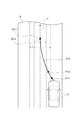
ここで、走行計画及び制御幅の具体例について説明する。図2は、走行計画の目標制御値に目標位置が含まれている場合における、目標位置及び目標位置の制御幅の設定を説明するための平面図である。図2に示すRは、車両Vが走行する走行車線である。実線で示すL1及びL2は、走行車線Rと隣接車線等との境界となる白線である。破線で示すTは、走行計画の複数の目標位置をつないだ目標軌跡である。Wは、目標位置の制御幅である。制御幅Wは、目標位置をつないだ目標軌跡Tの法線方向であって制御幅境界線Waと制御幅境界線Wbとの間の長さとして表すことができる。制御幅境界線Waは、目標位置毎に生成された制御幅において車両Vの左側の最大値同士をつないだ曲線である。制御幅境界線Wbは、目標位置毎に生成された制御幅において車両Vの右側の最大値同士をつないだ曲線である。図2では、制御幅が後述する走行車線の幅によって設定される場合を例として示しており、その結果、制御幅Wが一定となっている場合を示している。 Here, a specific example of the travel plan and the control width will be described. FIG. 2 is a plan view for explaining the setting of the target position and the control width of the target position when the target control value of the travel plan includes the target position. R shown in FIG. 2 is a traveling lane in which the vehicle V travels. L1 and L2 shown by solid lines are white lines that are boundaries between the traveling lane R and the adjacent lanes and the like. The T indicated by the broken line is a target locus connecting a plurality of target positions in the travel plan. W is the control width of the target position. The control width W can be expressed as the length between the control width boundary line Wa and the control width boundary line Wb in the normal direction of the target locus T connecting the target positions. The control width boundary line Wa is a curve connecting the maximum values on the left side of the vehicle V in the control width generated for each target position. The control width boundary line Wb is a curve connecting the maximum values on the right side of the vehicle V in the control width generated for each target position. FIG. 2 shows a case where the control width is set by the width of the traveling lane, which will be described later, as an example, and as a result, shows a case where the control width W is constant.
図2では、目標位置の制御幅Wの中央が、目標位置をつないだ目標軌跡Tとなる場合を示した。これに対し、走行計画生成部14は、目標位置をつないだ目標軌跡Tに対して車両Vの右側或いは左側に片寄るように制御幅Wを生成してもよい。例えば、図3に示すように、走行車線Rの左側に隣接して側壁Sが存在する場合、走行計画生成部14は、側壁Sから離れる側に片寄るように制御幅Wを生成してもよい。このように、走行計画生成部14は、例えば、周辺情報認識部12によって認識される側壁S等の障害物の位置等に応じて、制御幅を目標位置に対して片寄らせて生成してもよい。走行計画生成部14は、目標位置の制御幅を片寄らせて生成することに限定されず、他の目標制御値の制御幅についても目標制御値に対して片寄らせて生成してもよい。制御幅の片寄らせ方として、例えば、走行計画生成部14は、障害物から離れるように目標制御値に対して制御幅を片寄らせてもよい。
FIG. 2 shows a case where the center of the control width W of the target position is the target locus T connecting the target positions. On the other hand, the travel
図4(a)は、走行計画の目標制御値に目標ヨー角が含まれている場合における、目標ヨー角及び目標ヨー角の制御幅の設定を説明するための図である。図4(a)では、目標制御値の目標ヨー角の時間変化、及び目標ヨー角の制御幅の時間変化の一例を示している。破線で示すT1は、左回り又は右回りの目標制御値の目標ヨー角の時間変化を示す。点線で示すWa1は、左回り又は右回りにおける目標ヨー角の制御幅の上限を示す制御幅境界線である。点線で示すWb1は、左回り又は右回りにおける目標ヨー角の制御幅の下限を示す制御幅境界線である。W1は、目標ヨー角の制御幅である。制御幅W1は、制御幅の上限である制御幅境界線Wa1から制御幅の下限である制御幅境界線Wb1までの角度として表すことができる。走行計画生成部14は、目標ヨー角の制御幅W1についても、目標ヨー角T1に対して制御幅W1を片寄らせて生成してもよい。
FIG. 4A is a diagram for explaining the setting of the target yaw angle and the control width of the target yaw angle when the target control value of the travel plan includes the target yaw angle. FIG. 4A shows an example of a time change of the target yaw angle of the target control value and a time change of the control width of the target yaw angle. T1 shown by the broken line indicates the time change of the target yaw angle of the counterclockwise or clockwise target control value. Wa1 shown by the dotted line is a control width boundary line indicating the upper limit of the control width of the target yaw angle in the counterclockwise or clockwise direction. Wb1 shown by a dotted line is a control width boundary line indicating the lower limit of the control width of the target yaw angle in the counterclockwise or clockwise direction. W1 is the control width of the target yaw angle. The control width W1 can be expressed as an angle from the control width boundary line Wa1 which is the upper limit of the control width to the control width boundary line Wb1 which is the lower limit of the control width. The travel
図4(b)は、走行計画の目標制御値に目標速度が含まれている場合における、目標速度及び目標速度の制御幅の設定を説明するための図である。図4(b)では、目標制御値の目標速度の時間変化、及び目標速度の制御幅の時間変化の一例を示している。破線で示すT2は、目標制御値の目標速度の時間変化を示す。点線で示すWa2は、目標速度の制御幅の上限を示す制御幅境界線である。点線で示すWb2は、目標速度の制御幅の下限を示す制御幅境界線である。W2は、目標速度の制御幅である。制御幅W2は、制御幅の上限である制御幅境界線Wa2から制御幅の下限である制御幅境界線Wb2までの間の速度として表すことができる。走行計画生成部14は、目標速度の制御幅W2についても、目標速度T2に対して制御幅W2を片寄らせて生成してもよい。
FIG. 4B is a diagram for explaining the setting of the target speed and the control width of the target speed when the target speed is included in the target control value of the travel plan. FIG. 4B shows an example of a time change of the target speed of the target control value and a time change of the control width of the target speed. T2 shown by the broken line indicates the time change of the target speed of the target control value. Wa2 shown by a dotted line is a control width boundary line indicating an upper limit of the control width of the target speed. Wb2 shown by the dotted line is a control width boundary line indicating the lower limit of the control width of the target speed. W2 is the control range of the target speed. The control width W2 can be expressed as a speed between the control width boundary line Wa2 which is the upper limit of the control width and the control width boundary line Wb2 which is the lower limit of the control width. The travel
図4(c)は、走行計画の目標制御値に目標軌跡の曲率が含まれている場合における、目標軌跡の曲率及び曲率の制御幅の設定を説明するための図である。図4(c)では、目標軌跡の曲率の時間変化、及び曲率の制御幅の時間変化の一例を示している。破線で示すT3は、目標軌跡の曲率の時間変化を示す。点線で示すWa3は、曲率の制御幅の上限を示す制御幅境界線である。点線で示すWb3は、曲率の制御幅の下限を示す制御幅境界線である。W3は、曲率の制御幅である。制御幅W3は、制御幅の上限である制御幅境界線Wa3から制御幅の下限である制御幅境界線Wb3までの間の曲率として表すことができる。走行計画生成部14は、曲率の制御幅W3についても、目標軌跡の曲率T3に対して制御幅W3を片寄らせて生成してもよい。
FIG. 4C is a diagram for explaining the setting of the curvature of the target locus and the control width of the curvature when the target control value of the travel plan includes the curvature of the target locus. FIG. 4C shows an example of the time change of the curvature of the target locus and the time change of the control width of the curvature. T3 shown by the broken line indicates the time change of the curvature of the target locus. Wa3 shown by a dotted line is a control width boundary line indicating an upper limit of the control width of curvature. Wb3 shown by a dotted line is a control width boundary line indicating a lower limit of the control width of curvature. W3 is the control width of the curvature. The control width W3 can be expressed as a curvature between the control width boundary line Wa3 which is the upper limit of the control width and the control width boundary line Wb3 which is the lower limit of the control width. The travel
図4(d)は、走行計画の目標制御値に目標加速度が含まれている場合における、目標加速度及び目標加速度の制御幅の設定を説明するための図である。図4(d)では、目標制御値の目標加速度の時間変化、及び目標加速度の制御幅の時間変化の一例を示している。破線で示すT4は、目標制御値の目標加速度の時間変化を示す。点線で示すWa4は、目標加速度の制御幅の上限を示す制御幅境界線である。点線で示すWb4は、目標加速度の制御幅の下限を示す制御幅境界線である。W4は、目標加速度の制御幅である。制御幅W4は、制御幅の上限である制御幅境界線Wa4から制御幅の下限である制御幅境界線Wb4までの間の加速度として表すことができる。走行計画生成部14は、目標加速度の制御幅W4についても、目標加速度T4に対して制御幅W4を片寄らせて生成してもよい。
FIG. 4D is a diagram for explaining the setting of the target acceleration and the control width of the target acceleration when the target control value of the travel plan includes the target acceleration. FIG. 4D shows an example of a time change of the target acceleration of the target control value and a time change of the control width of the target acceleration. T4 shown by the broken line indicates the time change of the target acceleration of the target control value. Wa4 shown by the dotted line is a control width boundary line indicating the upper limit of the control width of the target acceleration. Wb4 shown by the dotted line is a control width boundary line indicating the lower limit of the control width of the target acceleration. W4 is the control range of the target acceleration. The control width W4 can be expressed as an acceleration between the control width boundary line Wa4 which is the upper limit of the control width and the control width boundary line Wb4 which is the lower limit of the control width. The travel
次に、走行計画生成部14が生成する制御幅の設定の一例について説明する。走行計画生成部14は、例えば、周辺情報である車両Vの走行車線の幅に基づいて、制御幅を生成してもよい。この場合、走行計画生成部14は、図5(a)に示すように、走行車線の幅が広い場合には、走行車線の幅が狭い場合に比べて制御幅を大きくしてもよい。走行計画生成部14は、走行車線の幅を、例えば、周辺情報認識部12から取得することによって認識してもよい。
Next, an example of setting the control width generated by the travel
走行計画生成部14は、例えば、周辺情報である車両Vの周辺を走行する周辺車両の大きさに基づいて、制御幅を生成してもよい。周辺車両とは、例えば、車両Vの前方を走行する車両であって、車両Vの走行車線を走行する車両或いは車両Vの走行車線に隣接する隣接車線を走行する車両であってもよい。周辺車両の大きさとは、車幅方向の大きさ、或いは前後方向の大きさであってもよい。この場合、走行計画生成部14は、図5(b)に示すように、周辺車両の大きさが大きい場合には、周辺車両の大きさが小さい場合に比べて制御幅を小さくしてもよい。走行計画生成部14は、周辺車両の大きさを、例えば、周辺情報認識部12から取得することによって認識してもよい。
The travel
走行計画生成部14は、例えば、周辺情報である車両Vの周辺を走行する周辺車両の速度に基づいて、制御幅を生成してもよい。この場合、走行計画生成部14は、図5(c)に示すように、周辺車両の速度が速い場合には、周辺車両の速度が遅い場合に比べて制御幅を小さくしてもよい。走行計画生成部14は、周辺車両の速度を、例えば、周辺情報認識部12から取得することによって認識してもよい。
The travel
走行計画生成部14は、例えば、周辺情報である車両Vの周辺を走行する周辺車両と車両Vの目標軌跡との距離に基づいて、制御幅を生成してもよい。この場合、走行計画生成部14は、図5(d)に示すように、周辺車両と車両Vの目標軌跡との距離が離れている場合には、周辺車両と車両Vの目標軌跡との距離が近い場合に比べて制御幅を大きくしてもよい。走行計画生成部14は、周辺車両と車両Vの目標軌跡との距離を、例えば周辺情報認識部12から取得することによって認識してもよい。
The travel
走行計画生成部14は、例えば、車両情報に含まれる車両Vの特性情報である車両Vの大きさに基づいて、制御幅を生成してもよい。車両Vの大きさとは、車幅方向の大きさ、或いは前後方向の大きさであってもよい。この場合、走行計画生成部14は、車両Vの大きさが大きい場合には、車両Vの大きさが小さい場合に比べて制御幅を小さくしてもよい。走行計画生成部14は、車両Vの大きさを、例えば、車両状態認識部13から取得することによって認識してもよい。
The travel
走行計画生成部14は、例えば、周辺情報である車両Vの走行車線の道路種別情報に基づいて、制御幅を生成してもよい。この場合、走行計画生成部14は、走行車線が高速道路である場合には、一般道路である場合に比べて制御幅を大きくしてもよい。走行計画生成部14は、道路種別情報を、例えば、周辺情報認識部12から取得することによって認識してもよい。走行計画生成部14は、例えば、周辺情報である車両Vの走行車線の制限速度に基づいて、制御幅を生成してもよい。この場合、走行計画生成部14は、制限速度が速い場合には、制限速度が遅い場合に比べて制御幅を小さくしてもよい。ここで、例えば、制限速度は、地図データベース4が備える地図情報に含まれていてもよい。この場合、周辺情報認識部12は、制限速度を地図データベース4から周辺情報として取得する。そして、走行計画生成部14は、種変情報としての制限速度を周辺情報認識部12から取得することによって認識してもよい。
The travel
走行計画生成部14は、例えば、車両Vの車両状態に含まれる走行状態に基づいて、制御幅を生成してもよい。この場合、走行計画生成部14は、走行状態である車両Vの速度が速い場合には、車両Vの速度が遅い場合に比べて制御幅を小さくしてもよい。走行計画生成部14は、車両Vの速度を、例えば、車両状態認識部13から取得することによって認識してもよい。走行計画生成部14は、走行状態である車両Vのヨーレートが大きい場合には、車両Vのヨーレートが小さい場合に比べて制御幅を小さくしてもよい。この場合、走行計画生成部14は、ヨーレートを、例えば、車両状態認識部13から取得することによって認識してもよい。走行計画生成部14は、走行状態である車両Vの前後方向の加速度又は横加速度が大きい場合には、車両Vの前後方向の加速度又は横加速度が小さい場合に比べて制御幅を小さくしてもよい。この場合、走行計画生成部14は、前後方向の加速度又は横加速度を、例えば、車両状態認識部13から取得することによって認識してもよい。
The travel
走行計画生成部14は、例えば、周辺情報である周辺車両が車両Vに対して近づいてくる速度(車両Vに対する障害物の相対速度)に基づいて、制御幅を生成してもよい。この場合、走行計画生成部14は、周辺車両が車両Vに対して近づいてくる速度が速い場合には、周辺車両が車両Vに対して近づいてくる速度が遅い場合に比べて制御幅を小さくしてもよい。走行計画生成部14は、周辺車両が車両Vに対して近づいてくる速度を、周辺情報認識部12から取得することによって認識してもよい。
The travel
走行計画生成部14は、例えば、周辺情報である車両Vの右側に存在する走行車線の境界線の色及び線種に基づいて、制御幅を生成してもよい。例えば、車両Vが日本国内を走行している場合、走行計画生成部14は、走行車線の右側の境界線の色が黄色であるときには、走行車線の右側の境界線が白色の破線であるときに比べて制御幅を小さくしてもよい。例えば、走行車線の右側の境界線の色が黄色である場合には、はみ出し通行禁止の境界線であるため、この境界線を踏まないように車両Vを走行させる必要がある。このため、走行計画生成部14は、走行車線の右側の境界線の色が黄色である場合に、走行車線の右側の境界線が白色の破線である場合に比べて制御幅を小さくする。走行計画生成部14は、車両Vの右側に存在する走行車線の境界線の色及び線種を、周辺情報認識部12から取得することによって認識してもよい。
The travel
走行計画生成部14は、例えば、車両情報に含まれる特性情報であるセンサの信頼度に基づいて、制御幅を生成してもよい。ここでの信頼度とは、走行計画の生成に用いた外部センサ1及び内部センサ3が備えるセンサの信頼度であってもよい。この場合、走行計画生成部14は、センサの信頼度が低い場合には、センサの信頼度が高い場合に比べて制御幅を小さくしてもよい。走行計画生成部14は、センサの信頼度を、例えば、車両状態認識部13から取得することによって認識してもよい。
The travel
走行計画生成部14は、例えば、周辺情報である車両Vの走行路の側方の平坦エリアの広さに基づいて、制御幅を生成してもよい。この場合、走行計画生成部14は、平坦エリアが狭い場合には、平坦エリアが広い場合に比べて制御幅を小さくしてもよい。走行計画生成部14は、平坦エリアの広さを、例えば、周辺情報認識部12から取得することによって認識してもよい。
The travel
走行計画生成部14は、例えば、周辺情報である車両Vの走行路の路面の状態に基づいて、制御幅を生成してもよい。例えば、走行計画生成部14は、路面が雨等によって濡れている場合には、路面が濡れていない場合に比べて制御幅を小さくしてもよい。走行計画生成部14は、路面の状態を、例えば、周辺情報認識部12から取得することによって認識してもよい。
The travel
上記において、走行計画生成部14は、様々な周辺情報及び様々な車両状態のいずれか一つに基づいて制御幅を生成したが、様々な周辺情報及び様々な車両状態のうち、何れか2以上に基づいて制御幅を生成してもよい。
In the above, the travel
走行制御部15は、走行計画生成部14で生成された走行計画及び制御幅に基づいて、車両Vの走行を自動で制御する。具体的には、走行制御部15は、走行計画生成部14で生成された走行計画及び制御幅と、車両状態認識部13で認識された車両状態とに基づいて、車両Vの車両状態が走行計画の目標制御値に対応する目標車両状態になるように指令制御値を演算する。走行制御部15は、演算した指令制御値をアクチュエータ6に出力する。これにより、走行制御部15は、走行計画に追従して車両Vが自動走行するように、車両Vの走行を制御する。なお、目標制御値に対応する目標車両状態とは、走行計画の目標制御値に応じたアクチュエータ6の出力によって実現される目標となる車両Vの車両状態である。
The
より詳細には、走行制御部15は、現在の車両状態が走行計画の目標制御値に対応する目標車両状態でないとき、車両状態を目標車両状態に近づける。この際、走行制御部15は、まず、車両状態認識部13によって認識された現在の車両状態が目標制御値の制御幅内に対応する車両状態であるか否かを判定する。走行制御部15は、現在の車両状態が目標制御値の制御幅内に対応する車両状態であるとき、現在の車両状態が制御幅外に対応する車両状態であるときと比べて、車両状態を緩やかに目標車両状態に近づけるように指令制御値を演算する。
More specifically, the
具体的には、走行制御部15は、例えば、現在の車両位置が目標位置の制御幅内の位置である場合、現在の車両位置が制御幅外の位置である場合と比べて、単位時間(例えば1分)内における目標位置へ近づく移動量を小さくするように指令制御値を演算する。走行制御部15は、例えば、現在の車両位置が目標位置の制御幅内の位置である場合、目標車両状態に車両Vの車両状態を早期に近づけるよりも乗り心地を優先して車両状態を緩やかに目標車両状態に近づけるように指令制御値を演算する。同様に、走行制御部15は、例えば、現在の車両Vの速度が目標速度の制御幅内の速度である場合、目標車両状態に車両Vの車両状態を早期に近づけるよりも乗り心地を優先して車両状態を緩やかに目標車両状態に近づけるように指令制御値を演算する。なお、乗り心地を優先して車両状態を緩やかに目標車両状態に近づけることとは、例えば、車両Vに生じる横加速度が予め定められた基準値以下となるように、車両状態を目標車両状態に近づけることであってもよい。
Specifically, for example, when the current vehicle position is within the control width of the target position, the
一方、走行制御部15は、車両状態認識部13によって認識された現在の車両状態が制御幅内に対応する車両状態でないとき、現在の車両状態が制御幅内に対応する車両状態であるときと比べて、車両状態を早期に目標車両状態に近づけるように指令制御値を演算する。具体的には、走行制御部15は、例えば、現在の車両位置が目標位置の制御幅外の位置である場合、現在の車両位置が制御幅内の位置である場合と比べて、単位時間(例えば1分)内における目標位置へ近づく移動量を大きくするように指令制御値を演算する。走行制御部15は、例えば、現在の車両位置が目標位置の制御幅外の位置である場合、乗り心地よりも目標車両状態に車両Vの車両状態を早期に近づけることを優先して指令制御値を演算する。同様に、走行制御部15は、例えば、現在の車両Vの速度が目標速度の制御幅外の速度である場合、乗り心地よりも目標車両状態に車両Vの車両状態を早期に近づけることを優先して指令制御値を演算する。
On the other hand, the traveling
すなわち、制御幅が小さい場合においては、車両状態が制御幅外に対応する車両状態であるときに車両状態を目標車両状態に近づける際に、制御幅が大きい場合に比べて、早期に目標車両状態に近づくように車両状態を制御する時間が長く、緩やかに目標車両状態に近づくように車両状態を制御する時間が短い。このため、自動運転車両システム100は、目標車両状態に対する車両Vの車両状態の追従性を高めることができる。一方、制御幅が大きい場合においては、車両状態が制御幅外に対応する車両状態であるときに車両状態を目標車両状態に近づける際に、制御幅が小さい場合に比べて、早期に目標車両状態に近づくように車両状態を制御する時間が短く、緩やかに目標車両状態に近づくように車両状態を制御する時間が長い。このため、自動運転車両システム100は、車両Vの急激な挙動の変化等を抑制し、乗り心地を向上させることができる。
That is, when the control width is small, when the vehicle state is a vehicle state corresponding to outside the control width and the vehicle state is brought closer to the target vehicle state, the target vehicle state is earlier than when the control width is large. The time to control the vehicle state so as to approach the target vehicle state is long, and the time to control the vehicle state to gradually approach the target vehicle state is short. Therefore, the self-driving
一例として、走行制御部15が走行計画に追従するように車両Vの走行を制御した場合における車両位置の変化について説明する。図2に示すように、走行車線Rを車両Vが走行しているとする。車両Vの車両位置は、目標位置の制御幅W外とする。車両Vの車両位置が制御幅W外であるため、走行制御部15は、車両位置が目標位置をつないだ目標軌跡Tに早期に追従するように車両Vを走行させる。このときの車両Vの軌跡を軌跡K1とする。車両位置が目標位置の制御幅W内となった場合、走行制御部15は、車両位置が目標位置をつないだ目標軌跡Tに緩やかに追従するように車両Vを走行させる。このときの車両Vの軌跡を軌跡K2とする。このように、走行制御部15は、車両Vの車両位置が目標位置の制御幅W内であるときは、車両Vの車両位置が目標位置の制御幅W外であるときよりも、車両位置を緩やかに目標位置に近づける。
As an example, a change in the vehicle position when the
次に、自動運転車両システム100で実行される処理の流れについて説明する。まず、ECU10が走行計画及び制御幅を生成する処理の流れについて、図6のフローチャートを参照しつつ具体的に説明する。例えば運転者がナビゲーションシステム5で目的地を設定し、自動走行を作動させる入力操作をHMI7に行うと、ECU10は、以下の走行計画及び制御幅を生成する処理を所定の処理周期で繰り返し実行する。
Next, the flow of processing executed by the autonomous
まず、車両状態認識部13は、車両Vの車両状態を認識する。周辺情報認識部12は、車両Vの周辺情報を認識する(S11)。走行計画生成部14は、車両Vの周辺情報と地図データベース4の地図情報とに基づいて、予め設定された目標ルートに沿った走行計画を生成する(S12)。走行計画生成部14は、周辺情報認識部12によって認識された車両Vの周辺情報、及び車両状態認識部13によって認識された車両状態の少なくともいずれかに基づいて制御幅を生成する(S13)。走行計画生成部14は、生成した走行計画及び制御幅を走行制御部15に出力する。
First, the vehicle
次に、ECU10が走行計画及び制御幅に基づいて車両Vの走行を制御する処理の流れについて、図7のフローチャートを参照しつつ具体的に説明する。走行制御部15は、走行計画生成部14によって走行計画及び制御幅が生成されると、車両Vの走行の制御を開始する。また、走行計画生成部14によって走行計画及び制御幅が新たに生成されると、走行制御部15は、新たに生成された走行計画及び制御幅に基づいて車両Vの走行を制御する。
Next, the flow of the process in which the
まず、走行制御部15は、現在の車両状態が目標制御値の制御幅内に対応する車両状態であるか否かを判定する(S21)。現在の車両状態が目標制御値の制御幅内に対応する車両状態であるとき(S21:YES)、走行制御部15は、現在の車両状態が制御幅外に対応する車両状態であるときと比べて、車両状態を緩やかに目標車両状態に近づけるように指令制御値を演算する。そして、走行制御部15は、演算した指令制御値をアクチュエータ6に出力する。このように、走行制御部15は、緩やかに目標車両状態に近づくように車両Vの走行を制御する(S22)。
First, the
現在の車両状態が目標制御値の制御幅内に対応する車両状態でないとき(S21:NO)、走行制御部15は、現在の車両状態が制御幅内に対応する車両状態であるときと比べて、車両状態を早期に目標車両状態に近づけるように指令制御値を演算する。そして、走行制御部15は、演算した指令制御値をアクチュエータ6に出力する。このように、走行制御部15は、早期に目標車両状態に近づくように車両Vの走行を制御する(S23)。
When the current vehicle state is not the vehicle state corresponding to the control range of the target control value (S21: NO), the traveling
以上、本実施形態の自動運転車両システム100では、現在の車両状態が制御幅内に対応する車両状態であるときは、現在の車両状態が制御幅外に対応する車両状態であるときと比べて車両状態を緩やかに目標車両状態に近づける。すなわち、自動運転車両システム100は、現在の車両状態が制御幅外に対応する車両状態であるときは、現在の車両状態が制御幅内に対応する車両状態であるときと比べて車両状態を早期に目標車両状態に近づける。このように、自動運転車両システム100は、車両状態が走行計画から大きく逸脱しているとき(現在の車両状態が制御幅外に対応する車両状態であるとき)には、早期に車両状態を走行計画の目標車両状態に近づけることができる。また、自動運転車両システム100は、車両状態が走行計画から小さく逸脱しているとき(現在の車両状態が制御幅内に対応する車両状態であるとき)には、緩やかに車両状態を走行計画の目標車両状態に近づけることで乗り心地を向上させることができる。
As described above, in the automatic
なお、走行制御部15は、指令制御値を演算する際に、車両状態を目標車両状態に近づけるための基本となる指令制御値を演算した後、車両状態が目標制御値の制御幅内である場合には車両状態が緩やかに目標車両状態に近づくように基本となる指令制御値を補正し、車両状態が目標制御値の制御幅外である場合には車両状態が早期に目標車両状態に近づくように基本となる指令制御値を補正してもよい。なお、基本となる指令制御値とは、車両状態が目標制御値の制御幅内であるか制御幅外であるかに関わらず、車両状態を目標車両状態に近づけるために必要な指令制御値である。この基本となる指令制御値は、車両状態が目標制御値の制御幅内であるか制御幅外であるかに応じて、上述したように補正される。或いは、走行制御部15は、車両状態を目標車両状態に近づけるための基本となる指令制御値を予め演算せずに、車両状態が目標制御値の制御幅内であるか否かに応じて、車両状態を緩やかに又は早期に目標車両状態に近づけるための指令制御値を演算してもよい。
When calculating the command control value, the
[第2実施形態]
次に、第2実施形態について説明する。本実施形態の説明では、第1実施形態と異なる点について詳細に説明し、第1実施形態と同一又は相当要素には同一符号を用い、重複する説明は省略する。図8は、第2実施形態に係る自動運転車両システム100Aの構成を示すブロック図である。自動運転車両システム100Aは、外部センサ1、GPS受信部2、内部センサ3、地図データベース4、ナビゲーションシステム5、アクチュエータ6、第1のECU10A、第2のECU10B、及びHMI7を備えている。なお、本実施形態は、第1実施形態に対して、走行計画生成部14と走行制御部15とが異なるECUに含まれている点が異なっている。
[Second Embodiment]
Next, the second embodiment will be described. In the description of this embodiment, the points different from those of the first embodiment will be described in detail, the same reference numerals will be used for the same or equivalent elements as those of the first embodiment, and duplicate description will be omitted. FIG. 8 is a block diagram showing a configuration of the autonomous
第1のECU10A及び第2のECU10Bは、車両Vの自動走行を制御する。第1のECU10Aは、CPU、ROM、RAM等を有する電子制御ユニットである。第1のECU10Aでは、ROMに記憶されているプログラムをRAMにロードし、CPUで実行することで、各種の制御を実行する。
The
第1のECU10Aは、機能的には、周辺情報認識部12、車両状態認識部13、及び走行計画生成部14を含んでいる。本実施形態における周辺情報認識部12、車両状態認識部13、及び走行計画生成部14が行う処理内容は、第1実施形態における周辺情報認識部12、車両状態認識部13、及び走行計画生成部14が行う処理内容と同様である。また、本実施形態における周辺情報認識部12及び車両状態認識部13は、第1実施形態において図6を用いて説明したS11の処理を行う。本実施形態における走行計画生成部14は、第1実施形態において図6を用いて説明したS12及びS13の処理を行う。
The
第2のECU10Bは、CPU、ROM、RAM等を有する電子制御ユニットである。第2のECU10Bでは、ROMに記憶されているプログラムをRAMにロードし、CPUで実行することで、各種の制御を実行する。
The
第2のECU10Bは、機能的には、走行制御部(第1の演算部)15を含んでいる。本実施形態における走行制御部15が行う処理内容は、第1実施形態における走行制御部15が行う処理内容と同様である。また、本実施形態に走行制御部15は、第1実施形態において図7を用いて説明したS21〜S23の処理を行う。
The
第1のECU10Aと第2のECU10Bとは、物理的に互いに異なるECUである。第1のECU10Aと第2のECU10Bとは、通信回線を介して互いに通信を行う。
The
以上、本実施形態の自動運転車両システム100Aでは、走行計画生成部14と走行制御部15とが異なるECUに含まれているので、例えば、第1のECU10Aを車種をまたいで採用する共通要素とし、第2のECU10Bを車種毎に異なる車種別要素とすることができる。これにより、走行計画生成部14及び走行制御部15が一つのECUに含まれている場合に比べて、要素の共通化を進めることができる。
As described above, in the automatic
また、本実施形態の自動運転車両システム100Aでは、第1実施形態と同様の効果を得ることができる。
Further, in the automatic
[第3実施形態]
次に、第3実施形態について説明する。本実施形態の説明では、第1実施形態と異なる点について詳細に説明し、第1実施形態と同一又は相当要素には同一符号を用い、重複する説明は省略する。図9は、第3実施形態に係る自動運転車両システム100Bの構成を示すブロック図である。自動運転車両システム100Bは、外部センサ1、GPS受信部2、内部センサ3、地図データベース4、ナビゲーションシステム5、アクチュエータユニット60、ECU20、及びHMI7を備えている。なお、本実施形態は、第1実施形態に対して、アクチュエータユニット60のアクチュエータ制御部62が制御幅に基づいてアクチュエータ61を制御する点が主に異なっている。
[Third Embodiment]
Next, the third embodiment will be described. In the description of the present embodiment, the points different from those of the first embodiment will be described in detail, the same reference numerals will be used for the same or equivalent elements as those of the first embodiment, and duplicate description will be omitted. FIG. 9 is a block diagram showing a configuration of the autonomous
ECU20は、車両Vの自動走行を制御する。ECU20は、CPU、ROM、RAM等を有する電子制御ユニットである。ECU20では、ROMに記憶されているプログラムをRAMにロードし、CPUで実行することで、各種の制御を実行する。ECU20は、複数の電子制御ユニットから構成されていてもよい。
The
ECU20は、機能的には、周辺情報認識部12、車両状態認識部13、走行計画生成部14、及び走行制御部(第2の演算部)15Bを含んでいる。本実施形態における周辺情報認識部12、車両状態認識部13、及び走行計画生成部14が行う処理内容は、第1実施形態における周辺情報認識部12、車両状態認識部13、及び走行計画生成部14が行う処理内容と同様である。また、本実施形態における周辺情報認識部12及び車両状態認識部13は、第1実施形態において図6を用いて説明したS11の処理を行う。本実施形態における走行計画生成部14は、第1実施形態において図6を用いて説明したS12及びS13の処理を行う。
Functionally, the
走行制御部15Bは、走行計画生成部14で生成された走行計画に基づいて、車両Vの走行を自動で制御する。具体的には、走行制御部15Bは、走行計画生成部14で生成された走行計画、及び車両状態認識部13で認識された車両状態に基づいて、車両Vの車両状態が走行計画の目標制御値に対応する目標車両状態になるように指令制御値を演算する。走行制御部15Bは、演算した指令制御値をアクチュエータユニット60に出力する。これにより、走行制御部15Bは、走行計画に追従して車両Vが自動走行するように、車両Vの走行を制御する。また、走行制御部15Bは、演算した指令制御値と共に、走行計画生成部14で生成された制御幅をアクチュエータユニット60に出力する。走行制御部15Bは、第1実施形態及び第2実施形態における走行制御部15とは異なり、指令制御値を演算するときに制御幅を用いない。
The
アクチュエータユニット60は、アクチュエータ61、及びアクチュエータ制御部62を含んでいる。アクチュエータ61は、第1実施形態におけるアクチュエータ6と同じである。アクチュエータ61には、走行計画生成部14で生成された指令制御値が入力される。アクチュエータ61は、指令制御値に応じた出力により車両Vの走行を制御する。
The
アクチュエータ制御部62は、車両状態認識部13によって認識された車両状態、及び走行計画生成部14によって生成された制御幅に基づいて、アクチュエータ61のパラメータを制御する。アクチュエータ61のパラメータとは、例えば、指令制御値に対するアクチュエータ61のフィードバックのゲインである。アクチュエータ制御部62は、アクチュエータ61のパラメータを制御することによって、アクチュエータ61の動作の応答性を変化させる。ここで、動作の応答性を変化させることとは、走行制御部15Bから入力された指令制御値にアクチュエータ61の出力値を到達させるために必要な時間を変化させることである。具体的には、アクチュエータ制御部62は、例えば、アクチュエータ61のパラメータを制御することとして、指令制御値に対するアクチュエータ61のフィードバックのゲインを変更してもよい。これにより、アクチュエータ制御部62は、車両Vの車両状態を、走行計画の目標制御値に対応する目標車両状態に早期に近づける、或いは緩やかに近づけることができる。
The
なお、アクチュエータ制御部62は、上記ゲインの変更に加えて、アクチュエータ61のパラメータを制御することとして、アクチュエータ61において制御的に許容される出力の最大値を変更してもよい。
In addition to changing the gain, the
より詳細には、アクチュエータ制御部62は、まず、車両状態認識部13によって認識された現在の車両状態が目標制御値の制御幅内に対応する車両状態であるか否かを判定する。アクチュエータ制御部62は、現在の車両状態が目標制御値の制御幅内に対応する車両状態であるとき、現在の車両状態が制御幅外に対応する車両状態であるときと比べて、アクチュエータ61の出力を緩やかに指令制御値に応じた出力に近づけるようにパラメータを変更する。一方、アクチュエータ制御部62は、車両状態認識部13によって認識された現在の車両状態が制御幅内に対応する車両状態でないとき、現在の車両状態が制御幅内に対応する車両状態であるときと比べて、アクチュエータ61の出力を早期に指令制御値に応じた出力に近づけるようにパラメータを変更する(例えば、パラメータを戻す)。
More specifically, the
一例として、アクチュエータ61の出力が指令制御値に応じた出力になるようにアクチュエータ61が制御された場合における車両位置の変化について説明する。図2に示すように、走行車線Rを車両Vが走行しているとする。車両Vの車両位置は、目標位置の制御幅W外とする。車両Vの車両位置が制御幅W外であるため、アクチュエータ制御部62は、アクチュエータ61の出力が指令制御値に対応する出力に早期に近づくようにアクチュエータ61のパラメータを制御する。このときの車両Vの軌跡を軌跡K1とする。車両位置が目標位置の制御幅W内となった場合、アクチュエータ制御部62は、アクチュエータ61の出力が指令制御値に対応する出力に緩やかに近づくようにアクチュエータ61のパラメータを制御する。このときの車両Vの軌跡を軌跡K2とする。これにより、車両Vの車両位置は、車両位置が目標位置の制御幅W内であるときは、車両位置が目標位置の制御幅W外であるときよりも、緩やかに目標位置に近づく。
As an example, a change in the vehicle position when the
次に、自動運転車両システム100Bで実行される処理の流れについて説明する。ECU20が走行計画及び制御幅を生成する処理の流れは、第1実施形態において図6を用いて説明した処理の流れと同様であり説明を省略する。すなわち、本実施形態における周辺情報認識部12及び車両状態認識部13は、第1実施形態において図6を用いて説明したS11の処理を行う。本実施形態における走行計画生成部14は、第1実施形態において図6を用いて説明したS12及びS13の処理を行う。
Next, the flow of processing executed by the autonomous
次に、走行制御部15Bが指令制御値を演算し、アクチュエータ制御部62が制御幅に基づいてアクチュエータ61のパラメータを制御する処理の流れについて、図10のフローチャートを参照しつつ具体的に説明する。走行制御部15Bは、走行計画生成部14によって走行計画及び制御幅が生成されると、走行計画生成部14で生成された走行計画、及び車両状態認識部13で認識された車両状態に基づいて、車両Vの車両状態が走行計画の目標制御値に対応する目標車両状態になるように指令制御値を演算する(S31)。走行制御部15Bは、演算した指令制御値と、走行計画生成部14が生成した制御幅とをアクチュエータユニット60に出力する。
Next, the flow of processing in which the traveling
アクチュエータ制御部62は、車両状態認識部13によって認識された現在の車両状態が目標制御値の制御幅内に対応する車両状態であるか否かを判定する(S32)。現在の車両状態が目標制御値の制御幅内に対応する車両状態であるとき(S32:YES)、アクチュエータ制御部62は、現在の車両状態が制御幅外に対応する車両状態であるときと比べて、アクチュエータ61の出力が指令制御値に対応する出力に緩やかに近づくようにアクチュエータ61のパラメータを制御する(S33)。これにより、車両Vの車両状態は、緩やかに目標車両状態に近づく。
The
車両状態認識部13によって認識された現在の車両状態が目標制御値の制御幅内に対応する車両状態でないとき(S32:NO)、アクチュエータ制御部62は、現在の車両状態が制御幅内に対応する車両状態であるときと比べて、アクチュエータ61の出力が指令制御値に対応する出力に早期に近づくようにアクチュエータ61のパラメータを制御する(S34)。これにより、車両Vの車両状態は、早期に目標車両状態に近づく。
When the current vehicle state recognized by the vehicle
走行制御部15及びアクチュエータ制御部62は、走行計画生成部14によって新たな走行計画及び制御幅が生成されるまで、現在の走行計画及び制御幅に基づいて、S31〜S34の処理を行う。
The
以上、本実施形態の自動運転車両システム100Bでは、現在の車両状態が制御幅内に対応する車両状態であるときは、現在の車両状態が制御幅外に対応する車両状態であるときと比べてアクチュエータ61の出力を緩やかに指令制御値に応じた出力に近づける。すなわち、自動運転車両システム100Bは、現在の車両状態が制御幅外に対応する車両状態であるときは、現在の車両状態が制御幅内に対応する車両状態であるときと比べてアクチュエータ61の出力を早期に指令制御値に応じた出力に近づける。これにより、自動運転車両システム100Bは、車両状態が走行計画から大きく逸脱しているとき(現在の車両状態が制御幅外に対応する車両状態であるとき)には、早期に車両状態を走行計画の目標車両状態に近づけることができる。また、自動運転車両システム100Bは、車両状態が走行計画から小さく逸脱しているとき(現在の車両状態が制御幅内に対応する車両状態であるとき)には、緩やかに車両状態を走行計画の目標車両状態に近づけることで乗り心地を向上させることができる。
As described above, in the autonomous
なお、第3実施形態においてアクチュエータ制御部62は、必ずしも、アクチュエータ61とユニット化されている必要はない。例えば、アクチュエータ制御部62は、ECU20内に含まれていてもよく、ECU20とは別のECUに含まれていてもよい。
In the third embodiment, the
また、走行制御部15Bは、制御幅に基づいて演算したアクチュエータ61の制御のパラメータの幅を制御幅の代わりにアクチュエータユニット60に出力してもよい。この場合、アクチュエータ制御部62は、現在のアクチュエータ61の制御のパラメータが、走行制御部15Bから入力されたアクチュエータ61の制御のパラメータの幅内のときに、現在の車両状態が目標制御値の制御幅内に対応する車両状態であると判定してもよい。また、アクチュエータ制御部62は、現在のアクチュエータ61の制御のパラメータが、走行制御部15Bから入力されたアクチュエータ61の制御のパラメータの幅外のときに、現在の車両状態が目標制御値の制御幅外に対応する車両状態であると判定してもよい。
Further, the
[第4実施形態]
次に、第4実施形態について説明する。本実施形態の説明では、第3実施形態と異なる点について詳細に説明し、第3実施形態と同一又は相当要素には同一符号を用い、重複する説明は省略する。図11は、第4実施形態に係る自動運転車両システム100Cの構成を示すブロック図である。自動運転車両システム100Cは、外部センサ1、GPS受信部2、内部センサ3、地図データベース4、ナビゲーションシステム5、アクチュエータ6、第1のECU20A、第2のECU20B、及びHMI7を備えている。なお、本実施形態は、第3実施形態に対して、走行計画生成部14と走行制御部15Bとが異なるECUに含まれている点が異なっている。
[Fourth Embodiment]
Next, the fourth embodiment will be described. In the description of the present embodiment, the points different from those of the third embodiment will be described in detail, the same reference numerals will be used for the same or equivalent elements as those of the third embodiment, and duplicate description will be omitted. FIG. 11 is a block diagram showing a configuration of the autonomous
第1のECU20A及び第2のECU20Bは、車両Vの自動走行を制御する。第1のECU20Aは、CPU、ROM、RAM等を有する電子制御ユニットである。第1のECU20Aでは、ROMに記憶されているプログラムをRAMにロードし、CPUで実行することで、各種の制御を実行する。
The
第1のECU20Aは、機能的には、周辺情報認識部12、車両状態認識部13、及び走行計画生成部14を含んでいる。本実施形態における周辺情報認識部12、車両状態認識部13、及び走行計画生成部14が行う処理内容は、第1実施形態における周辺情報認識部12、車両状態認識部13、及び走行計画生成部14が行う処理内容と同様である。また、本実施形態における周辺情報認識部12及び車両状態認識部13は、第1実施形態において図6を用いて説明したS11の処理を行う。本実施形態における走行計画生成部14は、第1実施形態において図6を用いて説明したS12及びS13の処理を行う。
The
第2のECU20Bは、CPU、ROM、RAM等を有する電子制御ユニットである。第2のECU20Bでは、ROMに記憶されているプログラムをRAMにロードし、CPUで実行することで、各種の制御を実行する。
The
第2のECU20Bは、機能的には、走行制御部(第2の演算部)15Bを含んでいる。本実施形態における走行制御部15Bが行う処理内容は、第3実施形態における走行制御部15Bが行う処理内容と同様である。また、本実施形態に走行制御部15Bは、第3実施形態において図10を用いて説明したS31の処理を行う。
The
第1のECU20Aと第2のECU20Bとは、物理的に互いに異なるECUである。第1のECU20Aと第2のECU20Bとは、通信回線を介して互いに通信を行ってもよい。
The
以上、本実施形態の自動運転車両システム100Cでは、走行計画生成部14と走行制御部15Bとが異なるECUに含まれているので、例えば、第1のECU20Aを車種をまたいで採用する共通要素とし、第2のECU20Bを車種毎に異なる車種別要素とすることができる。これにより、走行計画生成部14及び走行制御部15Bが一つのECUに含まれている場合に比べて、要素の共通化を進めることができる。
As described above, in the automatic
また、本実施形態の自動運転車両システム100Cでは、第3実施形態と同様の効果を得ることができる。
Further, in the automatic
なお、第4実施形態においてアクチュエータ制御部62は、必ずしも、アクチュエータ61とユニット化されている必要はない。例えば、アクチュエータ制御部62は、第2のECU20B内に含まれていてもよく、第2のECU20Bとは別のECUに含まれていてもよい。
In the fourth embodiment, the
以上、本発明の実施形態について説明したが、本発明は、上記実施形態に限定されるものではない。以下、種々の変形例について説明する。 Although the embodiments of the present invention have been described above, the present invention is not limited to the above embodiments. Hereinafter, various modifications will be described.
[第1変形例]
第1変形例において、例えば、第1実施形態における走行計画生成部14は、走行計画における車両Vの目標制御値の制御幅(以下「第1の制御幅」という)を生成し、第1の制御幅を含むように第1の制御幅よりも広い幅を有する第2の制御幅を生成してもよい。この場合、走行制御部15は、現在の車両状態が目標制御値の第2の制御幅内且つ第1の制御幅外に対応する車両状態であるとき、現在の車両状態が第2の制御幅外に対応する車両状態であるときと比べて、車両状態を緩やかに目標車両状態に近づけるように指令制御値を演算する。また、走行制御部15は、現在の車両状態が目標制御値の第1の制御幅内に対応する車両状態であるとき、現在の車両状態が第2の制御幅内且つ第1の制御幅外に対応する車両状態であるときと比べて、車両状態を緩やかに目標車両状態に近づけるように指令制御値を演算する。このように、車両Vの車両状態が目標車両状態に近づくにしたがって、車両状態を目標車両状態に近づける際の緩やかさを、段階的に緩やかにしてもよい。
[First modification]
In the first modification, for example, the travel
なお、走行計画生成部14は、第1の制御幅及び第2の制御幅を生成した場合と同様に、3つ以上の制御幅を生成してもよい。この場合、走行制御部15は、車両Vの車両状態が目標車両状態に近づくにしたがって、車両状態を目標車両状態に近づける際の緩やかさを、段階的に緩やかにしてもよい。
The travel
一例として、走行計画生成部14が第1の制御幅及び第2の制御幅を生成した場合における車両位置の変化について説明する。図12に示すように、走行車線Rを車両Vが走行しているとする。走行計画生成部14は、目標位置の制御幅として、第1の制御幅W11、及び第2の制御幅W12を生成したとする。車両Vの車両位置は、目標位置の第2の制御幅W12外とする。車両Vの車両位置が目標位置の第2の制御幅W12外であるため、走行制御部15は、車両位置が目標位置をつないだ目標軌跡Tに早期に追従するように車両Vを走行させる。このときの車両Vの軌跡を軌跡K11とする。車両位置が目標位置の第2の制御幅W12内且つ第1の制御幅W11外となった場合、走行制御部15は、車両位置が第2の制御幅W12外の場合と比べて、車両位置が目標位置をつないだ目標軌跡Tに緩やかに追従するように車両Vを走行させる。このときの車両Vの軌跡を軌跡K12とする。車両位置が目標位置の第1の制御幅W11内となった場合、走行制御部15は、車両位置が第2の制御幅W12内且つ第1の制御幅W11外の場合と比べて、車両位置が目標位置をつないだ目標軌跡Tに緩やかに追従するように車両Vを走行させる。このときの車両Vの軌跡を軌跡K13とする。このように、車両位置が目標位置に近づくにつれて車両位置をより緩やかに目標位置に近づけてもよい。
As an example, a change in the vehicle position when the travel
なお、第2実施形態においても第1変形例と同様に、走行計画生成部14が複数の制御幅を生成し、複数生成された制御幅に基づいて走行制御部15が車両Vの走行を制御してもよい。
In the second embodiment as well, as in the first modification, the travel
[第2変形例]
第1変形例と同様に、第2変形例において、例えば、第3実施形態における走行計画生成部14は、走行計画における車両Vの目標制御値の第1の制御幅を生成し、第1の制御幅を含むように第1の制御幅よりも広い幅を有する第2の制御幅を生成してもよい。この場合、アクチュエータ制御部62は、現在の車両状態が目標制御値の第2の制御幅内且つ第1の制御幅外に対応する車両状態であるとき、現在の車両状態が第2の制御幅外に対応する車両状態であるときと比べて、アクチュエータ61の出力値を緩やかに指令制御値に近づけるようにパラメータを変更する。また、アクチュエータ制御部62は、現在の車両状態が目標制御値の第1の制御幅内に対応する車両状態であるとき、現在の車両状態が第2の制御幅内且つ第1の制御幅外に対応する車両状態であるときと比べて、アクチュエータ61の出力値を緩やかに指令制御値に近づけるようにパラメータを変更する。このように、車両Vの車両状態が目標車両状態に近づくにしたがって、アクチュエータ61の出力値を指令制御値に近づける際の緩やかさを、段階的に緩やかにしてもよい。
[Second modification]
Similar to the first modification, in the second modification, for example, the travel
なお、走行計画生成部14は、第1の制御幅及び第2の制御幅を生成した場合と同様に、3つ以上の制御幅を生成してもよい。この場合、アクチュエータ制御部62は、車両Vの車両状態が目標車両状態に近づくにしたがって、アクチュエータ61の出力値を指令制御値に近づける際の緩やかさを、段階的に緩やかにしてもよい。
The travel
一例として、走行計画生成部14が第1の制御幅及び第2の制御幅を生成した場合における車両位置の変化について説明する。図12に示すように、走行車線Rを車両Vが走行しているとする。走行計画生成部14は、目標位置の制御幅として、第1の制御幅W11、及び第2の制御幅W12を生成したとする。車両Vの車両位置は、目標位置の第2の制御幅W12外とする。車両Vの車両位置が目標位置の第2の制御幅W12外であるため、アクチュエータ制御部62は、アクチュエータ61の出力値が早期に指令制御値に近づくようにパラメータを変更する。このときの車両Vの軌跡を軌跡K11とする。車両位置が目標位置の第2の制御幅W12内且つ第1の制御幅W11外となった場合、アクチュエータ制御部62は、車両位置が第2の制御幅W12外の場合と比べて、アクチュエータ61の出力値が緩やかに指令制御値に近づくようにパラメータを変更する。このときの車両Vの軌跡を軌跡K12とする。車両位置が目標位置の第1の制御幅W11内となった場合、アクチュエータ制御部62は、車両位置が第2の制御幅W12内且つ第1の制御幅W11外の場合と比べて、アクチュエータ61の出力値が緩やかに指令制御値に近づくようにパラメータを変更する。このときの車両Vの軌跡を軌跡K13とする。このように、車両位置が目標位置に近づくにつれてアクチュエータ61の出力値が緩やかに指令制御値に近づくようにパラメータを変更してもよい。
As an example, a change in the vehicle position when the travel
なお、第4実施形態においても第2変形例と同様に、走行計画生成部14が複数の制御幅を生成し、複数生成された制御幅に基づいてアクチュエータ制御部62がアクチュエータ61のパラメータを制御してもよい。
In the fourth embodiment as well, as in the second modification, the travel
[第3変形例]
第3変形例において、例えば、第1実施形態における走行制御部15は、周辺情報及び車両情報の少なくともいずれかに基づいて制御幅下限値(制御幅の最小値)を演算し、演算した制御幅下限値を走行計画生成部14に出力してもよい。そして、走行計画生成部14は、制御幅を生成する際に、入力された制御幅下限値以上となるように制御幅を生成してもよい。制御幅下限値とは、目標車両状態となるように車両Vの車両状態を制御した場合における制御誤差の最大値であってもよい。制御誤差の最大値は、例えば、車両Vの車両状態、車両Vの走行に関わる特性、車両Vの走行の制御に使用するセンサの信頼度、及び路面の状態のうち少なくともいずれかに基づいて演算されてもよい。
[Third variant]
In the third modification, for example, the
例えば、車両Vの車両状態とは、車両Vの速度、及び空気圧センサによって検出された車両Vのタイヤの空気圧などであってもよい。車両Vの速度が速い場合、走行制御部15は、車両Vの速度が遅い場合に比べて制御誤差の最大値が大きくなるように、制御誤差の最大値を演算してもよい。また、タイヤの空気圧が低い場合、走行制御部15は、タイヤの空気圧が高い場合に比べて制御誤差の最大値が大きくなるように、制御誤差の最大値を演算してもよい。例えば、車両Vの走行に関わる特性とは、ブレーキ性能、及び加速性能などであってもよい。ブレーキ性能が低い場合、走行制御部15は、ブレーキ性能が高い場合に比べて制御誤差の最大値が大きくなるように、制御誤差の最大値を演算してもよい。また、加速性能が低い場合、走行制御部15は、加速性能が高い場合に比べて制御誤差の最大値が大きくなるように、制御誤差の最大値を演算してもよい。例えば、車両Vの走行の制御に使用するセンサの信頼度とは、車速センサの信頼度などであってもよい。車速センサの信頼度が低い場合、走行制御部15は、車速センサの信頼度が高い場合に比べて制御誤差の最大値が大きくなるように、制御誤差の最大値を演算してもよい。例えば、路面の状態とは、路面が乾いている状態、路面が濡れている状態である。路面が濡れている場合、走行制御部15は、路面が乾いている場合に比べて制御誤差の最大値が大きくなるように、制御誤差の最大値を演算してもよい。
For example, the vehicle state of the vehicle V may be the speed of the vehicle V, the tire pressure of the vehicle V detected by the air pressure sensor, or the like. When the speed of the vehicle V is high, the
なお、例えば自動運転車両システム100は、システム起動開始時(例えば、イグニッションON時)において、車両Vの走行に関わる特性、車両Vの走行の制御に使用するセンサの信頼度として、予め設定された標準値を用いてもよい。標準値とは、例えば、一般的な車両状態を想定した値であってもよく、車両の制御性が最も悪いときの車両状態を想定した値であってもよい。例えば自動運転車両システム100は、システム起動開始時において、路面の状態として、乾いた路面状態或いは濡れた路面状態を用いてもよい。車両Vが走行を開始した後、自動運転車両システム100は、走行中における各種センサ等における検出結果に基づいて標準値を更新してもよい。
For example, the autonomous
走行計画生成部14は、周辺情報認識部12によって認識された車両Vの周辺情報、及び車両状態認識部13によって認識された車両状態の少なくともいずれかに基づいて制御幅を生成する際に、走行制御部15から入力された制御幅下限値以上となるように制御幅を生成する。このように、走行制御部15から入力された制御幅下限値以上となるように走行計画生成部14が制御幅を生成することにより、走行制御部15は、制御幅内において、車両Vの車両状態が目標車両状態となるように車両Vの走行を制御することができる。
The travel
ここで、走行計画生成部14が周辺情報認識部12によって認識された車両Vの周辺情報、及び車両状態認識部13によって認識された車両状態の少なくともいずれかに基づいて制御幅を生成する際に、走行制御部15から入力された制御幅下限値以上となるように制御幅を生成することができない場合が考えられる。具体的には、例えば、車両Vが高速走行を行っている状態で走行車線の幅が狭い場合、走行計画生成部14は小さな制御幅を生成しようとする。このとき、走行計画生成部14は、制御幅下限値以上の制御幅を生成できないことがある。このような場合、ECU10は、例えば、車両Vを減速させて制御幅を生成可能な状態にしてもよい。或いは、ECU10は、車両Vの走行計画を再度生成してもよい。ECU10は、自動運転制御を停止させてもよい。ECU10は、制御幅下限値以上の制御幅を生成できない旨を運転者へ警告をする等の対応を行ってもよい。
Here, when the travel
走行制御部15が走行計画生成部14に出力する制御幅下限値は、一つでも良く、複数でもよい。例えば、制御幅下限値が速度に依存する場合、走行制御部15は、速度毎の制御幅下限値を生成して走行計画生成部14に出力してもよい。この場合、例えば、走行計画生成部14は、制御幅を生成する際に、走行計画に含まれる速度に応じた制御幅下限値に基づいて制御幅を生成してもよい。制御幅下限値を複数設ける場合には、最も小さい制御幅下限値よりも小さい制御幅しか生成できない場合に、ECU10は、上述したように車両Vを減速させて制御幅を生成可能な状態にしてもよい。同様に、ECU10は、車両Vの走行計画を再度生成してもよい。或いは、ECU10は、自動運転制御を停止させてもよい。ECU10は、制御幅下限値以上の制御幅を生成できない旨を運転者へ警告をする等の対応を行ってもよい。
The lower limit value of the control width output by the
なお、第2実施形態においても第3変形例と同様に、走行制御部15が制御幅下限値を生成して走行計画生成部14に出力してもよい。そして、走行計画生成部14は、入力された制御幅下限値以上となるように制御幅を生成してもよい。第3実施形態及び第4実施形態においても第3変形例と同様に、走行制御部15Bが制御幅下限値を生成して走行計画生成部14に出力してもよい。そして、走行計画生成部14は、入力された制御幅下限値以上となるように制御幅を生成してもよい。
In the second embodiment as well, the
10A,20A…第1のECU、10B,20B…第2のECU、12…周辺情報認識部、13…車両状態認識部、14…走行計画生成部、15…走行制御部(第1の演算部)、15B…走行制御部(第2の演算部)、6,61…アクチュエータ、62…アクチュエータ制御部、100,100A,100B,100C…自動運転車両システム、V…車両。 10A, 20A ... 1st ECU, 10B, 20B ... 2nd ECU, 12 ... Peripheral information recognition unit, 13 ... Vehicle state recognition unit, 14 ... Travel plan generation unit, 15 ... Travel control unit (1st calculation unit) ), 15B ... Travel control unit (second calculation unit), 6,61 ... Actuator, 62 ... Actuator control unit, 100, 100A, 100B, 100C ... Self-driving vehicle system, V ... Vehicle.
Claims (4)
前記車両の車両状態を認識する車両状態認識部と、
前記車両の前記周辺情報に基づいて走行計画を生成すると共に、前記車両状態及び前記周辺情報の少なくともいずれかに基づいて前記走行計画における前記車両の目標制御値の制御幅を生成する走行計画生成部と、
前記走行計画、前記車両状態及び前記制御幅に基づいて、前記車両状態が前記目標制御値に対応する目標車両状態になるように指令制御値を演算する第1の演算部と、
前記指令制御値に基づいて前記車両の走行を制御するアクチュエータと、
を備え、
前記第1の演算部は、現在の前記車両状態が前記制御幅外に対応する車両状態から前記制御幅内に対応する車両状態となった場合、前記車両状態が前記制御幅外に対応する車両状態であるときと比べて、前記車両状態を緩やかに前記目標車両状態に近づけるように前記指令制御値を演算する、自動運転車両システム。 Peripheral information recognition unit that recognizes peripheral information of the vehicle,
A vehicle state recognition unit that recognizes the vehicle state of the vehicle and
A travel plan generator that generates a travel plan based on the peripheral information of the vehicle and generates a control range of a target control value of the vehicle in the travel plan based on at least one of the vehicle state and the peripheral information. When,
A first calculation unit that calculates a command control value so that the vehicle state becomes a target vehicle state corresponding to the target control value based on the travel plan, the vehicle state, and the control width.
An actuator that controls the running of the vehicle based on the command control value,
With
When the current vehicle state changes from a vehicle state corresponding to the outside of the control width to a vehicle state corresponding to the inside of the control width, the first calculation unit is a vehicle whose vehicle state corresponds to the outside of the control width. An autonomous driving vehicle system that calculates the command control value so that the vehicle state gradually approaches the target vehicle state as compared with the state.
前記第1の演算部は、前記第1のECUとは異なる第2のECUに含まれる、請求項1に記載の自動運転車両システム。 The travel plan generation unit is included in the first ECU,
The autonomous driving vehicle system according to claim 1, wherein the first calculation unit is included in a second ECU different from the first ECU.
前記車両の車両状態を認識する車両状態認識部と、
前記車両の前記周辺情報に基づいて走行計画を生成すると共に、前記車両状態及び前記周辺情報の少なくともいずれかに基づいて前記走行計画における前記車両の目標制御値の制御幅を生成する走行計画生成部と、
前記走行計画に基づいて、前記車両状態が前記目標制御値に対応する目標車両状態になるように指令制御値を演算する第2の演算部と、
前記指令制御値に応じた出力により前記車両の走行を制御するアクチュエータと、
前記車両状態及び前記制御幅に基づいて前記アクチュエータのパラメータを制御するアクチュエータ制御部と、
を備え、
前記アクチュエータ制御部は、現在の前記車両状態が前記制御幅外に対応する車両状態から前記制御幅内に対応する車両状態となった場合、前記車両状態が前記制御幅外に対応する車両状態であるときと比べて、現在の前記アクチュエータの出力を緩やかに前記指令制御値に応じた出力に近づけるように前記パラメータを変更する、自動運転車両システム。 Peripheral information recognition unit that recognizes peripheral information of the vehicle,
A vehicle state recognition unit that recognizes the vehicle state of the vehicle and
A travel plan generator that generates a travel plan based on the peripheral information of the vehicle and generates a control range of a target control value of the vehicle in the travel plan based on at least one of the vehicle state and the peripheral information. When,
A second calculation unit that calculates a command control value so that the vehicle state becomes a target vehicle state corresponding to the target control value based on the travel plan.
An actuator that controls the running of the vehicle by an output corresponding to the command control value,
An actuator control unit that controls the parameters of the actuator based on the vehicle state and the control width.
With
When the current vehicle state changes from a vehicle state corresponding to the outside of the control width to a vehicle state corresponding to the inside of the control width , the actuator control unit is in a vehicle state in which the vehicle state corresponds to the outside of the control width. An autonomous vehicle system in which the parameters are changed so that the current output of the actuator gradually approaches the output corresponding to the command control value as compared with a certain time.
前記第2の演算部は、前記第1のECUとは異なる第2のECUに含まれる、請求項3に記載の自動運転車両システム。 The travel plan generation unit is included in the first ECU,
The autonomous driving vehicle system according to claim 3, wherein the second calculation unit is included in a second ECU different from the first ECU.
Priority Applications (9)
| Application Number | Priority Date | Filing Date | Title |
|---|---|---|---|
| JP2015090260A JP6791616B2 (en) | 2015-04-27 | 2015-04-27 | Self-driving vehicle system |
| RU2016115549A RU2638879C2 (en) | 2015-04-27 | 2016-04-21 | Automatic control system for vehicle |
| MYPI2016701475A MY186541A (en) | 2015-04-27 | 2016-04-21 | Automatic driving vehicle system |
| KR1020160049839A KR101846072B1 (en) | 2015-04-27 | 2016-04-25 | Automatic driving vehicle system |
| CA2928073A CA2928073C (en) | 2015-04-27 | 2016-04-25 | Automatic driving vehicle system |
| CN201610266618.1A CN106080744B (en) | 2015-04-27 | 2016-04-26 | Automatic driving vehicle system |
| US15/138,845 US9933783B2 (en) | 2015-04-27 | 2016-04-26 | Automatic driving vehicle system |
| EP16167308.2A EP3088281B1 (en) | 2015-04-27 | 2016-04-27 | Automatic driving vehicle system |
| BR102016009328-7A BR102016009328B1 (en) | 2015-04-27 | 2016-04-27 | AUTOMATIC DRIVING VEHICLE SYSTEM |
Applications Claiming Priority (1)
| Application Number | Priority Date | Filing Date | Title |
|---|---|---|---|
| JP2015090260A JP6791616B2 (en) | 2015-04-27 | 2015-04-27 | Self-driving vehicle system |
Related Child Applications (1)
| Application Number | Title | Priority Date | Filing Date |
|---|---|---|---|
| JP2020126424A Division JP2020185991A (en) | 2020-07-27 | 2020-07-27 | Self-driving vehicle system |
Publications (2)
| Publication Number | Publication Date |
|---|---|
| JP2016203882A JP2016203882A (en) | 2016-12-08 |
| JP6791616B2 true JP6791616B2 (en) | 2020-11-25 |
Family
ID=55919613
Family Applications (1)
| Application Number | Title | Priority Date | Filing Date |
|---|---|---|---|
| JP2015090260A Active JP6791616B2 (en) | 2015-04-27 | 2015-04-27 | Self-driving vehicle system |
Country Status (9)
| Country | Link |
|---|---|
| US (1) | US9933783B2 (en) |
| EP (1) | EP3088281B1 (en) |
| JP (1) | JP6791616B2 (en) |
| KR (1) | KR101846072B1 (en) |
| CN (1) | CN106080744B (en) |
| BR (1) | BR102016009328B1 (en) |
| CA (1) | CA2928073C (en) |
| MY (1) | MY186541A (en) |
| RU (1) | RU2638879C2 (en) |
Families Citing this family (53)
| Publication number | Priority date | Publication date | Assignee | Title |
|---|---|---|---|---|
| JP6791616B2 (en) | 2015-04-27 | 2020-11-25 | トヨタ自動車株式会社 | Self-driving vehicle system |
| KR102383426B1 (en) * | 2016-12-15 | 2022-04-07 | 현대자동차주식회사 | Apparatus and Method for determining toll gate section |
| US10353393B2 (en) * | 2016-12-29 | 2019-07-16 | Baidu Usa Llc | Method and system for improving stability of autonomous driving vehicles |
| CN106864361B (en) * | 2017-02-14 | 2019-04-30 | 驭势科技(北京)有限公司 | Method, system, device and the storage medium of vehicle and the outer people-car interaction of vehicle |
| WO2018179277A1 (en) * | 2017-03-30 | 2018-10-04 | 本田技研工業株式会社 | Vehicle control system, server device, vehicle control method, and vehicle control program |
| US20180284783A1 (en) * | 2017-03-31 | 2018-10-04 | GM Global Technology Operations LLC | Autonomous vehicle routing based on occupant characteristics |
| JP6558393B2 (en) * | 2017-04-06 | 2019-08-14 | トヨタ自動車株式会社 | Course setting device and course setting method |
| US10814913B2 (en) | 2017-04-12 | 2020-10-27 | Toyota Jidosha Kabushiki Kaisha | Lane change assist apparatus for vehicle |
| JP6885781B2 (en) * | 2017-05-11 | 2021-06-16 | 日立Astemo株式会社 | Vehicle control device, vehicle control method and vehicle control system |
| JP6653381B2 (en) * | 2017-05-22 | 2020-02-26 | バイドゥドットコム タイムズ テクノロジー (ベイジン) カンパニー リミテッドBaidu.com Times Technology (Beijing) Co., Ltd. | Map update method and system based on control feedback of autonomous vehicle |
| US11136027B2 (en) * | 2017-05-25 | 2021-10-05 | Honda Motor Co., Ltd. | Vehicle control device |
| JP6683178B2 (en) * | 2017-06-02 | 2020-04-15 | トヨタ自動車株式会社 | Automatic driving system |
| JP6704876B2 (en) * | 2017-06-02 | 2020-06-03 | 本田技研工業株式会社 | Automatic driving control system |
| JP6589941B2 (en) | 2017-06-06 | 2019-10-16 | トヨタ自動車株式会社 | Steering support device |
| JPWO2018230496A1 (en) * | 2017-06-16 | 2020-02-27 | 本田技研工業株式会社 | Map updating device, map updating system, map updating method, and program |
| JP6971315B2 (en) * | 2017-06-30 | 2021-11-24 | 日立Astemo株式会社 | Information management device |
| JP6780611B2 (en) | 2017-08-25 | 2020-11-04 | トヨタ自動車株式会社 | Autonomous driving device |
| US20190212747A1 (en) * | 2017-08-30 | 2019-07-11 | Continental Automotive Systems, Inc. | Lane Marker Signal Improvement through Mapped Geo-Referenced Lane Boundaries |
| JP6651486B2 (en) * | 2017-09-01 | 2020-02-19 | 本田技研工業株式会社 | Vehicle control device, vehicle control method, and program |
| CN111133398B (en) * | 2017-09-22 | 2023-09-26 | 伟摩有限责任公司 | Detecting movement of an autonomous vehicle using radar technology |
| CN108152827B (en) * | 2017-09-28 | 2020-09-18 | 北京卫星制造厂 | Omnidirectional intelligent mobile equipment positioning and navigation method based on laser ranging |
| JP2019067061A (en) * | 2017-09-29 | 2019-04-25 | アイシン・エィ・ダブリュ株式会社 | Driving support system, driving control system, route guidance system and driving support program |
| JP6881233B2 (en) * | 2017-10-27 | 2021-06-02 | 井関農機株式会社 | Work vehicle |
| JP6907896B2 (en) * | 2017-11-17 | 2021-07-21 | トヨタ自動車株式会社 | Autonomous driving system |
| JP6832303B2 (en) * | 2018-02-15 | 2021-02-24 | トヨタテクニカルディベロップメント株式会社 | Control device and its control method and control program |
| JP6725568B2 (en) | 2018-03-13 | 2020-07-22 | 本田技研工業株式会社 | Vehicle control device, vehicle, vehicle control method, and program |
| JP6971187B2 (en) * | 2018-03-28 | 2021-11-24 | 京セラ株式会社 | Image processing equipment, imaging equipment, and moving objects |
| US10843710B2 (en) | 2018-04-11 | 2020-11-24 | Hyundai Motor Company | Apparatus and method for providing notification of control authority transition in vehicle |
| US11597403B2 (en) | 2018-04-11 | 2023-03-07 | Hyundai Motor Company | Apparatus for displaying driving state of vehicle, system including the same and method thereof |
| JP6723301B2 (en) * | 2018-08-29 | 2020-07-15 | 三菱電機株式会社 | Vehicle steering system |
| CN109300488A (en) * | 2018-10-11 | 2019-02-01 | 惠州市德赛西威汽车电子股份有限公司 | A kind of LabVIEW pulse test system and method |
| TWI678305B (en) * | 2018-10-19 | 2019-12-01 | 財團法人車輛研究測試中心 | Automatic driving method and device with decision diagnosis |
| US10852727B2 (en) * | 2018-11-26 | 2020-12-01 | GM Global Technology Operations LLC | System and method for control of an autonomous vehicle |
| CN110617828B (en) * | 2018-12-29 | 2022-04-01 | 毫末智行科技有限公司 | Method and system for generating dynamic target line during automatic driving of vehicle and vehicle |
| CN109901574B (en) * | 2019-01-28 | 2021-08-13 | 华为技术有限公司 | Automatic driving method and device |
| CN109765902B (en) * | 2019-02-22 | 2022-10-11 | 阿波罗智能技术(北京)有限公司 | Unmanned vehicle driving reference line processing method and device and vehicle |
| JP7135977B2 (en) * | 2019-03-29 | 2022-09-13 | マツダ株式会社 | Arithmetic unit for vehicle |
| RU2750152C1 (en) * | 2019-04-25 | 2021-06-22 | Общество с ограниченной ответственностью "Яндекс Беспилотные Технологии" | Methods and systems for determining vehicle trajectory estimation procedure |
| DE102019206875B3 (en) * | 2019-05-13 | 2020-07-23 | Volkswagen Aktiengesellschaft | Detect a banquet trip of a motor vehicle |
| KR20210028421A (en) | 2019-09-04 | 2021-03-12 | 현대자동차주식회사 | Internal Verification Type ECU Integration System |
| JP7215391B2 (en) | 2019-10-15 | 2023-01-31 | トヨタ自動車株式会社 | Vehicle control system and vehicle control device for self-driving vehicle |
| JP7272241B2 (en) | 2019-11-18 | 2023-05-12 | トヨタ自動車株式会社 | Vehicle travel control device and vehicle control system |
| DE102020204078A1 (en) * | 2019-11-27 | 2021-05-27 | Robert Bosch Gesellschaft mit beschränkter Haftung | Driver assistance system for motor vehicles |
| JP7272291B2 (en) | 2020-01-27 | 2023-05-12 | トヨタ自動車株式会社 | vehicle control system |
| JP7053695B2 (en) * | 2020-02-14 | 2022-04-12 | 本田技研工業株式会社 | Vehicle control unit and vehicle |
| CN111880545A (en) * | 2020-02-17 | 2020-11-03 | 李华兰 | Automatic driving device, system, automatic driving decision processing method and device |
| CN113492863B (en) * | 2020-03-18 | 2023-03-10 | 北京车和家信息技术有限公司 | Automatic driving control method and device |
| JP7464425B2 (en) * | 2020-03-31 | 2024-04-09 | 本田技研工業株式会社 | Vehicle control device, vehicle control method, and program |
| JP2022032109A (en) * | 2020-08-11 | 2022-02-25 | 株式会社デンソー | Collision determination device, collision determination method, and collision avoidance system |
| DE102020121733A1 (en) * | 2020-08-19 | 2022-02-24 | Zf Cv Systems Global Gmbh | Method for automated driving of a vehicle, driving control unit and vehicle |
| RU2767826C1 (en) | 2021-05-24 | 2022-03-22 | Общество с ограниченной ответственностью «Яндекс Беспилотные Технологии» | Method and device for vehicle control |
| CN113895458B (en) * | 2021-10-26 | 2023-06-30 | 上海集度汽车有限公司 | Vehicle driving behavior management method and device, vehicle and storage medium |
| JP7632236B2 (en) | 2021-11-04 | 2025-02-19 | トヨタ自動車株式会社 | Vehicle control system and vehicle control method |
Family Cites Families (25)
| Publication number | Priority date | Publication date | Assignee | Title |
|---|---|---|---|---|
| RU2006385C1 (en) * | 1991-10-14 | 1994-01-30 | Научно-исследовательский институт радиоприборостроения | Device for automatic control of car movement in emergency situations |
| JP3022115B2 (en) | 1993-12-27 | 2000-03-15 | 日産自動車株式会社 | Control target changing device for in-vehicle control system |
| JP3292110B2 (en) * | 1997-09-22 | 2002-06-17 | トヨタ自動車株式会社 | Vehicle steering control device |
| JP3956693B2 (en) * | 2001-12-27 | 2007-08-08 | トヨタ自動車株式会社 | Integrated vehicle motion controller |
| DE102005024382A1 (en) * | 2005-05-27 | 2006-12-07 | Robert Bosch Gmbh | Lane departure warning for motor vehicles |
| DE102005052034A1 (en) * | 2005-10-31 | 2007-05-03 | Robert Bosch Gmbh | Lane keeping support system for motor vehicle, has steering controller, where steering characteristics of system is modified while cornering, such that smaller steering force is exerted on steering in direction of curve inner side |
| JP4952268B2 (en) | 2007-01-24 | 2012-06-13 | トヨタ自動車株式会社 | Travel control plan generator |
| JP2009061878A (en) * | 2007-09-05 | 2009-03-26 | Toyota Motor Corp | Travel control device |
| JP4978439B2 (en) | 2007-11-26 | 2012-07-18 | トヨタ自動車株式会社 | Vehicle travel support device |
| US8170739B2 (en) | 2008-06-20 | 2012-05-01 | GM Global Technology Operations LLC | Path generation algorithm for automated lane centering and lane changing control system |
| JP5298925B2 (en) * | 2009-02-18 | 2013-09-25 | 日産自動車株式会社 | Vehicle travel control apparatus and method |
| US8190330B2 (en) * | 2009-03-06 | 2012-05-29 | GM Global Technology Operations LLC | Model based predictive control for automated lane centering/changing control systems |
| JP2011005893A (en) * | 2009-06-23 | 2011-01-13 | Nissan Motor Co Ltd | Vehicular travel control device, and vehicular travel control method |
| JP5327333B2 (en) * | 2009-10-30 | 2013-10-30 | トヨタ自動車株式会社 | Vehicle travel control device |
| JP2011162132A (en) * | 2010-02-12 | 2011-08-25 | Toyota Motor Corp | Automatic driving device |
| JP5552339B2 (en) * | 2010-03-12 | 2014-07-16 | トヨタ自動車株式会社 | Vehicle control device |
| CN102939230B (en) * | 2010-06-16 | 2015-05-20 | 丰田自动车株式会社 | Driving assistance device |
| JP5609320B2 (en) * | 2010-06-30 | 2014-10-22 | 日産自動車株式会社 | Obstacle avoidance support device and obstacle avoidance support method |
| WO2012068331A1 (en) | 2010-11-19 | 2012-05-24 | Magna Electronics Inc. | Lane keeping system and lane centering system |
| JP5543501B2 (en) | 2012-01-27 | 2014-07-09 | 株式会社日本自動車部品総合研究所 | Vehicle control device |
| JP2014181020A (en) | 2013-03-21 | 2014-09-29 | Denso Corp | Travel control device |
| US9454150B2 (en) | 2013-07-17 | 2016-09-27 | Toyota Motor Engineering & Manufacturing North America, Inc. | Interactive automated driving system |
| US9227635B1 (en) * | 2014-09-25 | 2016-01-05 | Nissan North America, Inc. | Method and system of assisting a driver of a vehicle |
| JP6791616B2 (en) | 2015-04-27 | 2020-11-25 | トヨタ自動車株式会社 | Self-driving vehicle system |
| JP6361567B2 (en) * | 2015-04-27 | 2018-07-25 | トヨタ自動車株式会社 | Automated driving vehicle system |
-
2015
- 2015-04-27 JP JP2015090260A patent/JP6791616B2/en active Active
-
2016
- 2016-04-21 RU RU2016115549A patent/RU2638879C2/en active
- 2016-04-21 MY MYPI2016701475A patent/MY186541A/en unknown
- 2016-04-25 CA CA2928073A patent/CA2928073C/en active Active
- 2016-04-25 KR KR1020160049839A patent/KR101846072B1/en active IP Right Grant
- 2016-04-26 US US15/138,845 patent/US9933783B2/en active Active
- 2016-04-26 CN CN201610266618.1A patent/CN106080744B/en active Active
- 2016-04-27 BR BR102016009328-7A patent/BR102016009328B1/en active IP Right Grant
- 2016-04-27 EP EP16167308.2A patent/EP3088281B1/en active Active
Also Published As
| Publication number | Publication date |
|---|---|
| JP2016203882A (en) | 2016-12-08 |
| CA2928073C (en) | 2018-03-13 |
| RU2638879C2 (en) | 2017-12-18 |
| KR101846072B1 (en) | 2018-04-05 |
| CA2928073A1 (en) | 2016-10-27 |
| EP3088281B1 (en) | 2019-09-25 |
| US9933783B2 (en) | 2018-04-03 |
| BR102016009328A2 (en) | 2016-11-08 |
| CN106080744B (en) | 2019-03-29 |
| US20160313738A1 (en) | 2016-10-27 |
| RU2016115549A (en) | 2017-10-26 |
| KR20160127662A (en) | 2016-11-04 |
| BR102016009328B1 (en) | 2021-08-24 |
| MY186541A (en) | 2021-07-26 |
| EP3088281A1 (en) | 2016-11-02 |
| CN106080744A (en) | 2016-11-09 |
Similar Documents
| Publication | Publication Date | Title |
|---|---|---|
| JP6791616B2 (en) | Self-driving vehicle system | |
| JP6361567B2 (en) | Automated driving vehicle system | |
| US11769414B2 (en) | Autonomous driving device | |
| JP7172257B2 (en) | Autonomous driving system | |
| JP6859907B2 (en) | Vehicle control unit | |
| JP6344275B2 (en) | Vehicle control device | |
| JP6269534B2 (en) | Travel control device | |
| JP6555067B2 (en) | Lane change support device | |
| US20160325750A1 (en) | Travel control apparatus | |
| US9896098B2 (en) | Vehicle travel control device | |
| JP6705388B2 (en) | Automatic driving system | |
| CN105988467A (en) | Autonomous driving device | |
| CN106043302A (en) | Active cruise control system in vehicle and method thereof | |
| JP2017073059A (en) | Lane change support device | |
| JP6558261B2 (en) | Automatic driving device | |
| JP2020185991A (en) | Self-driving vehicle system |
Legal Events
| Date | Code | Title | Description |
|---|---|---|---|
| A621 | Written request for application examination |
Free format text: JAPANESE INTERMEDIATE CODE: A621 Effective date: 20170615 |
|
| A977 | Report on retrieval |
Free format text: JAPANESE INTERMEDIATE CODE: A971007 Effective date: 20180319 |
|
| A131 | Notification of reasons for refusal |
Free format text: JAPANESE INTERMEDIATE CODE: A131 Effective date: 20180403 |
|
| A131 | Notification of reasons for refusal |
Free format text: JAPANESE INTERMEDIATE CODE: A131 Effective date: 20180918 |
|
| A02 | Decision of refusal |
Free format text: JAPANESE INTERMEDIATE CODE: A02 Effective date: 20190219 |
|
| C60 | Trial request (containing other claim documents, opposition documents) |
Free format text: JAPANESE INTERMEDIATE CODE: C60 Effective date: 20190510 |
|
| C22 | Notice of designation (change) of administrative judge |
Free format text: JAPANESE INTERMEDIATE CODE: C22 Effective date: 20191210 |
|
| C22 | Notice of designation (change) of administrative judge |
Free format text: JAPANESE INTERMEDIATE CODE: C22 Effective date: 20200414 |
|
| C13 | Notice of reasons for refusal |
Free format text: JAPANESE INTERMEDIATE CODE: C13 Effective date: 20200526 |
|
| A521 | Request for written amendment filed |
Free format text: JAPANESE INTERMEDIATE CODE: A523 Effective date: 20200727 |
|
| C302 | Record of communication |
Free format text: JAPANESE INTERMEDIATE CODE: C302 Effective date: 20200811 |
|
| C23 | Notice of termination of proceedings |
Free format text: JAPANESE INTERMEDIATE CODE: C23 Effective date: 20200908 |
|
| C03 | Trial/appeal decision taken |
Free format text: JAPANESE INTERMEDIATE CODE: C03 Effective date: 20201013 |
|
| C30A | Notification sent |
Free format text: JAPANESE INTERMEDIATE CODE: C3012 Effective date: 20201013 |
|
| A61 | First payment of annual fees (during grant procedure) |
Free format text: JAPANESE INTERMEDIATE CODE: A61 Effective date: 20201105 |
|
| R151 | Written notification of patent or utility model registration |
Ref document number: 6791616 Country of ref document: JP Free format text: JAPANESE INTERMEDIATE CODE: R151 |