JP6783433B2 - Cup holder - Google Patents
Cup holder Download PDFInfo
- Publication number
- JP6783433B2 JP6783433B2 JP2017123520A JP2017123520A JP6783433B2 JP 6783433 B2 JP6783433 B2 JP 6783433B2 JP 2017123520 A JP2017123520 A JP 2017123520A JP 2017123520 A JP2017123520 A JP 2017123520A JP 6783433 B2 JP6783433 B2 JP 6783433B2
- Authority
- JP
- Japan
- Prior art keywords
- accommodating portion
- light source
- light
- guide lens
- light guide
- Prior art date
- Legal status (The legal status is an assumption and is not a legal conclusion. Google has not performed a legal analysis and makes no representation as to the accuracy of the status listed.)
- Active
Links
Images


Classifications
-
- B—PERFORMING OPERATIONS; TRANSPORTING
- B60—VEHICLES IN GENERAL
- B60N—SEATS SPECIALLY ADAPTED FOR VEHICLES; VEHICLE PASSENGER ACCOMMODATION NOT OTHERWISE PROVIDED FOR
- B60N3/00—Arrangements or adaptations of other passenger fittings, not otherwise provided for
- B60N3/10—Arrangements or adaptations of other passenger fittings, not otherwise provided for of receptacles for food or beverages, e.g. refrigerated
- B60N3/101—Arrangements or adaptations of other passenger fittings, not otherwise provided for of receptacles for food or beverages, e.g. refrigerated fixed
-
- B—PERFORMING OPERATIONS; TRANSPORTING
- B60—VEHICLES IN GENERAL
- B60Q—ARRANGEMENT OF SIGNALLING OR LIGHTING DEVICES, THE MOUNTING OR SUPPORTING THEREOF OR CIRCUITS THEREFOR, FOR VEHICLES IN GENERAL
- B60Q3/00—Arrangement of lighting devices for vehicle interiors; Lighting devices specially adapted for vehicle interiors
- B60Q3/20—Arrangement of lighting devices for vehicle interiors; Lighting devices specially adapted for vehicle interiors for lighting specific fittings of passenger or driving compartments; mounted on specific fittings of passenger or driving compartments
- B60Q3/225—Small compartments, e.g. glove compartments
- B60Q3/229—Cup holders
-
- B—PERFORMING OPERATIONS; TRANSPORTING
- B60—VEHICLES IN GENERAL
- B60Q—ARRANGEMENT OF SIGNALLING OR LIGHTING DEVICES, THE MOUNTING OR SUPPORTING THEREOF OR CIRCUITS THEREFOR, FOR VEHICLES IN GENERAL
- B60Q3/00—Arrangement of lighting devices for vehicle interiors; Lighting devices specially adapted for vehicle interiors
- B60Q3/60—Arrangement of lighting devices for vehicle interiors; Lighting devices specially adapted for vehicle interiors characterised by optical aspects
- B60Q3/62—Arrangement of lighting devices for vehicle interiors; Lighting devices specially adapted for vehicle interiors characterised by optical aspects using light guides
- B60Q3/64—Arrangement of lighting devices for vehicle interiors; Lighting devices specially adapted for vehicle interiors characterised by optical aspects using light guides for a single lighting device
-
- F—MECHANICAL ENGINEERING; LIGHTING; HEATING; WEAPONS; BLASTING
- F21—LIGHTING
- F21V—FUNCTIONAL FEATURES OR DETAILS OF LIGHTING DEVICES OR SYSTEMS THEREOF; STRUCTURAL COMBINATIONS OF LIGHTING DEVICES WITH OTHER ARTICLES, NOT OTHERWISE PROVIDED FOR
- F21V33/00—Structural combinations of lighting devices with other articles, not otherwise provided for
-
- F—MECHANICAL ENGINEERING; LIGHTING; HEATING; WEAPONS; BLASTING
- F21—LIGHTING
- F21V—FUNCTIONAL FEATURES OR DETAILS OF LIGHTING DEVICES OR SYSTEMS THEREOF; STRUCTURAL COMBINATIONS OF LIGHTING DEVICES WITH OTHER ARTICLES, NOT OTHERWISE PROVIDED FOR
- F21V5/00—Refractors for light sources
- F21V5/04—Refractors for light sources of lens shape
-
- F—MECHANICAL ENGINEERING; LIGHTING; HEATING; WEAPONS; BLASTING
- F21—LIGHTING
- F21V—FUNCTIONAL FEATURES OR DETAILS OF LIGHTING DEVICES OR SYSTEMS THEREOF; STRUCTURAL COMBINATIONS OF LIGHTING DEVICES WITH OTHER ARTICLES, NOT OTHERWISE PROVIDED FOR
- F21V7/00—Reflectors for light sources
- F21V7/0008—Reflectors for light sources providing for indirect lighting
-
- F—MECHANICAL ENGINEERING; LIGHTING; HEATING; WEAPONS; BLASTING
- F21—LIGHTING
- F21V—FUNCTIONAL FEATURES OR DETAILS OF LIGHTING DEVICES OR SYSTEMS THEREOF; STRUCTURAL COMBINATIONS OF LIGHTING DEVICES WITH OTHER ARTICLES, NOT OTHERWISE PROVIDED FOR
- F21V7/00—Reflectors for light sources
- F21V7/0025—Combination of two or more reflectors for a single light source
- F21V7/0033—Combination of two or more reflectors for a single light source with successive reflections from one reflector to the next or following
- F21V7/0041—Combination of two or more reflectors for a single light source with successive reflections from one reflector to the next or following for avoiding direct view of the light source or to prevent dazzling
-
- F—MECHANICAL ENGINEERING; LIGHTING; HEATING; WEAPONS; BLASTING
- F21—LIGHTING
- F21W—INDEXING SCHEME ASSOCIATED WITH SUBCLASSES F21K, F21L, F21S and F21V, RELATING TO USES OR APPLICATIONS OF LIGHTING DEVICES OR SYSTEMS
- F21W2107/00—Use or application of lighting devices on or in particular types of vehicles
- F21W2107/10—Use or application of lighting devices on or in particular types of vehicles for land vehicles
-
- G—PHYSICS
- G02—OPTICS
- G02B—OPTICAL ELEMENTS, SYSTEMS OR APPARATUS
- G02B6/00—Light guides; Structural details of arrangements comprising light guides and other optical elements, e.g. couplings
- G02B6/0001—Light guides; Structural details of arrangements comprising light guides and other optical elements, e.g. couplings specially adapted for lighting devices or systems
- G02B6/0011—Light guides; Structural details of arrangements comprising light guides and other optical elements, e.g. couplings specially adapted for lighting devices or systems the light guides being planar or of plate-like form
- G02B6/0013—Means for improving the coupling-in of light from the light source into the light guide
- G02B6/0015—Means for improving the coupling-in of light from the light source into the light guide provided on the surface of the light guide or in the bulk of it
- G02B6/0018—Redirecting means on the surface of the light guide
Landscapes
- Engineering & Computer Science (AREA)
- Mechanical Engineering (AREA)
- General Engineering & Computer Science (AREA)
- Physics & Mathematics (AREA)
- Thermal Sciences (AREA)
- Transportation (AREA)
- Passenger Equipment (AREA)
- Arrangements Of Lighting Devices For Vehicle Interiors, Mounting And Supporting Thereof, Circuits Therefore (AREA)
- Vehicle Step Arrangements And Article Storage (AREA)
Description
本発明は、カップホルダー、特に自動車の車室内等に装備されるカップホルダーに関する。 The present invention relates to a cup holder, particularly a cup holder installed in an automobile interior or the like.
従来、自動車の車室内のコンソールボックスやインストルメントパネルの全面等に設けられる、ペットボトルや飲料缶などの飲料容器を一時保管するのに便利なカップホルダーとして、カップ収納部の夜間の視認性や装飾性を向上させるための光源を備えたものが知られている(例えば、特許文献1、2参照)。 Conventionally, as a cup holder that is conveniently installed on the entire surface of the console box or instrument panel in the passenger compartment of an automobile and is convenient for temporarily storing beverage containers such as PET bottles and beverage cans, the visibility of the cup storage section at night and Those provided with a light source for improving the decorativeness are known (see, for example, Patent Documents 1 and 2).
特許文献1に記載のカップホルダーは、カップを収容するための2つのカップ収容部と、2つのカップ収容部の開口部にそれぞれ取り付けられた2つの環状の導光部材と、2つの導光部材にそれぞれ光を供給して発光させる2つの光源と、を備える。 The cup holder described in Patent Document 1 includes two cup accommodating portions for accommodating cups, two annular light guide members attached to openings of the two cup accommodating portions, and two light guide members. Each is provided with two light sources that supply light to emit light.
特許文献2に記載のカップホルダーは、カップを収容するための2つのカップ収容部と、2つのカップ収容部の開口部の縁に連続して設けられた透明リングと、透明リングに光を供給して発光させる光源と、を備える。 The cup holder described in Patent Document 2 supplies light to two cup accommodating portions for accommodating cups, a transparent ring provided continuously on the edge of an opening of the two cup accommodating portions, and a transparent ring. It is provided with a light source that emits light.
特許文献1に記載のカップホルダーによれば、2つのカップ収容部を照らすために2つの光源が必要となる。また、特許文献2に記載のカップホルダーによれば、1つの光源で2つのカップ収容部を照らすことができるが、2つのカップ収容部が等しい照度で照らされるため、暗い車室内において視認により2つのカップ収容部を容易に区別することができない。 According to the cup holder described in Patent Document 1, two light sources are required to illuminate the two cup accommodating portions. Further, according to the cup holder described in Patent Document 2, one light source can illuminate two cup accommodating portions, but since the two cup accommodating portions are illuminated with the same illuminance, it can be visually recognized in a dark vehicle interior. The two cup compartments cannot be easily distinguished.
本発明の目的の1つは、光源が1つである場合でも、視認により容易に区別できるように2つのカップ収容部を照らすことのできる構造を有するカップホルダーを提供することにある。 One of an object of the present invention is to provide a cup holder having a structure capable of illuminating two cup accommodating portions so that they can be easily distinguished visually even when there is only one light source.
本発明の一態様は、上記目的を達成するために、下記[1]〜[6]のカップホルダーを提供する。 One aspect of the present invention provides the following cup holders [1] to [6] in order to achieve the above object.
[1]カップを収容するための凹状の第1の収容部及び第2の収容部と、前記第1の収容部と前記第2の収容部の間の、前記第1の収容部の底部及び前記第2の収容部の底部よりも高い位置に設置された、前記第1の収容部の底部及び前記第2の収容部の底部を照らすための光源と、を備え、前記光源による前記第1の収容部の底部の照度が前記第2の収容部の底部の照度よりも高い構成を有する、カップホルダー。 [1] The bottom and bottom of the first accommodating portion between the concave first accommodating portion and the second accommodating portion for accommodating the cup and the first accommodating portion and the second accommodating portion. The first accommodating portion is provided with a light source for illuminating the bottom portion of the first accommodating portion and the bottom portion of the second accommodating portion, which is installed at a position higher than the bottom portion of the second accommodating portion. A cup holder having a configuration in which the illuminance at the bottom of the housing portion is higher than the illuminance at the bottom of the second housing portion.
[2]前記第1の収容部の底部の高さが、前記第2の収容部の底部の高さよりも高い、上記[1]に記載のカップホルダー。 [2] The cup holder according to the above [1], wherein the height of the bottom of the first accommodating portion is higher than the height of the bottom of the second accommodating portion.
[3]前記光源から発せられた光を前記第1の収容部の底部及び前記第2の収容部の底部へ導く導光レンズを前記光源の上に備え、前記導光レンズが、その中心よりも前記第1の収容部側に位置し、前記光源から発せられて前記導光レンズ内に進入した光を前記第1の収容部の底部に導く第1の領域と、その中心よりも前記第2の収容部側に位置し、前記光源から発せられて前記導光レンズ内に進入した光を前記第2の収容部の底部に導く第2の領域と、を有する平板状の導光レンズであって、前記導光レンズの前記第1の領域の形状と前記第2の領域の形状が非対称である、上記[1]又は[2]に記載のカップホルダー。 [3] A light guide lens that guides the light emitted from the light source to the bottom of the first accommodating portion and the bottom of the second accommodating portion is provided on the light source, and the light guide lens is from the center thereof. Is also located on the side of the first accommodating portion, and guides the light emitted from the light source and entering the light guide lens to the bottom of the first accommodating portion, and the first region from the center thereof. A flat plate-shaped light guide lens located on the side of the housing portion 2 and having a second region that guides the light emitted from the light source and entering the light guide lens to the bottom of the second housing portion. The cup holder according to the above [1] or [2], wherein the shape of the first region and the shape of the second region of the light guide lens are asymmetric.
[4]前記光源が設置された領域と前記第1の収容部とを空間的につなげる開口部の面積が、前記光源が設置された領域と前記第2の収容部とを空間的につなげる開口部の面積よりも大きい、上記[1]〜[3]のいずれか1項に記載のカップホルダー。 [4] The area of the opening that spatially connects the area where the light source is installed and the first accommodating portion is the opening that spatially connects the area where the light source is installed and the second accommodating portion. The cup holder according to any one of the above [1] to [3], which is larger than the area of the portion.
[5]前記光源が、前記第2の収容部よりも前記第1の収容部に近い位置に設置された、上記[1]〜[4]のいずれか1項に記載のカップホルダー。 [5] The cup holder according to any one of [1] to [4] above, wherein the light source is installed at a position closer to the first accommodating portion than the second accommodating portion.
[6]前記光源が1つである、上記[1]〜[5]のいずれか1項に記載のカップホルダー。 [6] The cup holder according to any one of the above [1] to [5], wherein the light source is one.
本発明によれば、光源が1つである場合でも、視認により容易に区別できるように2つのカップ収容部を照らすことのできる構造を有するカップホルダーを提供することができる。 According to the present invention, it is possible to provide a cup holder having a structure capable of illuminating two cup accommodating portions so that they can be easily distinguished visually even when there is only one light source.
〔第1の実施の形態〕
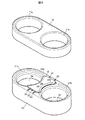
図1は、第1の実施の形態に係るカップホルダー1の斜視図である。図2は、カップホルダー1の上側部材10と下側部材20を分離した状態の斜視図である。また、図3は、カップホルダー1の垂直断面図である。
[First Embodiment]
FIG. 1 is a perspective view of the cup holder 1 according to the first embodiment. FIG. 2 is a perspective view of the cup holder 1 in a state where the
カップホルダー1は、カップを収容するための凹状の第1の収容部2a及び第2の収容部2bを有する。第1の収容部2a及び第2の収容部2bには、ペットボトル、飲料缶、コップ等の飲料容器を収容することができる。また、カップホルダー1は、積層された上側部材10と下側部材20から構成される。
The cup holder 1 has a concave first
カップホルダー1の第1の収容部2aは、上側部材10の第1の穴11aと下側部材20の第1の凹部21aから構成され、第2の収容部2bは、上側部材10の第2の穴11bと下側部材20の第2の凹部21bから構成される。第1の収容部2aの底部3aは、下側部材20の第1の凹部21aの底部であり、第2の収容部2bの底部3bは、下側部材20の第2の凹部21bの底部である。
The first
下側部材20の第1の凹部21aと第2の凹部21bの間の凸状の領域の上には、第1の収容部2aの底部3a及び第2の収容部2bの底部3bを照らすための、LED等の発光素子を含む光源4が設置されている。すなわち、光源4は、第1の収容部2aと第2の収容部2bの間の、第1の収容部2aの底部3a及び第2の収容部2bの底部3bよりも高い位置に設置されている。
To illuminate the
なお、カップホルダー1は、第1の収容部2aと第2の収容部2bの間の、第1の収容部2aの底部3a及び第2の収容部2bの底部3bよりも高い位置に複数の光源4を有してもよいが、製造コストの観点からは、光源4は1つであることが好ましい。
A plurality of cup holders 1 are provided between the first
また、光源4の上には、光源4から発せられた光を第1の収容部2aの底部3a及び第2の収容部2bの底部3bまで導くための導光レンズ5が設置されている。
Further, above the light source 4, a
導光レンズ5は、中心に設けられた円錐状の凹部51と、第1の収容部2a側の側面に設けられた傾斜面52aと、第2の収容部2b側の側面に設けられた傾斜面52bと、導光レンズ5を下側部材20の上に間隔を空けて保持するための保持部53を有する。なお、凹部51の形状は、四角錐、六角錐等の他の錐形状であってもよい。
The
図4は、導光レンズ5の垂直断面図である。導光レンズ5は、平板状の導光レンズであり、その中心よりも第1の収容部2a側に位置し、光源4から発せられて導光レンズ5内に進入した光を第1の収容部2aの底部3aに導く第1の領域5aと、その中心よりも第2の収容部2b側に位置し、光源4から発せられて導光レンズ5内に進入した光を第2の収容部2bの底部3bに導く第2の領域5bと、を有する。また、導光レンズ5の下部には、導光レンズ5を光源4に固定するための固定部54が設けられている。
FIG. 4 is a vertical cross-sectional view of the
導光レンズ5の第1の領域5aは、光源4から発せられて第1の領域5a内に進入した光を反射する傾斜面51aと、傾斜面51aで反射されて第1の領域5a内を進行する光を第1の収容部2aの底部3aへ向けて反射する傾斜面52aを含む。
The
導光レンズ5の第2の領域5bは、光源4から発せられて第2の領域5b内に進入した光を反射する傾斜面51bと、傾斜面51bで反射されて第2の領域5b内を進行する光を第2の領域5bの底部3bへ向けて反射する傾斜面52bを含む。
The
導光レンズ5の第1の領域5aに含まれる傾斜面51aと、第2の領域5bに含まれる傾斜面51bは、ともに錐形状の凹部51の斜面の一部である。
The
光源4から発せられた光は、導光レンズ5によって進行方向を第1の収容部2a側と第2の収容部2b側に分けられ、それぞれ開口部6a、6bを通過して、底部3a、3bに達する。
The light emitted from the light source 4 is divided into a first
ここで、開口部6aは、積層された上側部材10と下側部材20の隙間であり、光源4及び導光レンズ5が設置された領域と第1の収容部2aとを空間的につなげる開口部である。開口部6bは、積層された上側部材10と下側部材20の隙間であり、光源4及び導光レンズ5が設置された領域と第2の収容部2bとを空間的につなげる開口部である。
Here, the opening 6a is a gap between the laminated
本実施の形態に係るカップホルダー1においては、第1の収容部2aの底部3aの高さが、第2の収容部2bの底部3bの高さよりも高いため、光源4(導光レンズ5)から第1の収容部2aの底部3aまでの距離が、光源4(導光レンズ5)から第2の収容部2bの底部3bまでの距離よりも短い。このため、光源4による第1の収容部2aの底部3aの照度が、第2の収容部2bの底部3bの照度よりも高い。
In the cup holder 1 according to the present embodiment, the height of the
第1の収容部2aの底部3aと第2の収容部2bの底部3bの明るさが異なるため、第1の収容部2aと第2の収容部2bを視認により容易に区別することができる。
Since the brightness of the
〔第2の実施の形態〕
第2の実施の形態は、導光レンズ5の形状により光源4による第1の収容部2aの底部3aの照度を第2の収容部2bの底部3bの照度よりも高くする点において、第1の実施の形態と異なる。なお、以下に説明する本実施の形態の特徴である構成以外のカップホルダー1の構成は、第1の実施の形態と同じとすることができるものとする。
[Second Embodiment]
In the second embodiment, the shape of the
図5(a)、(b)は、第2の実施の形態に係る導光レンズ5の垂直断面図である。図5(a)、(b)に示される導光レンズ5においては、第1の領域5aの形状と第2の領域5bの形状が非対称である。
5 (a) and 5 (b) are vertical cross-sectional views of the
図5(a)に示される導光レンズ5においては、第1の領域5aの厚さtaが第2の領域5bの厚さtbよりも厚いため、傾斜面51a、傾斜面52aの面積が、それぞれ傾斜面51b、傾斜面52bの面積よりも大きい。このため、第1の領域5aにより第1の収容部2aに導かれる光の量が、第2の領域5bにより第2の収容部2bに導かれる光の量よりも多くなる。
In the
図5(b)に示される導光レンズ5においては、第1の領域5aの傾斜面51aの傾斜角θ1aが第2の領域5bの傾斜面51bの傾斜角θ1bと異なり、第1の領域5aの傾斜面52aの傾斜角θ2aが第2の領域5bの傾斜面52bの傾斜角θ2bと異なる。
In the
第1の領域5aの傾斜面51aの傾斜角θ1a及び傾斜面52aの傾斜角θ2aは、第2の領域5bの傾斜面51bの傾斜角θ1b及び傾斜面52bの傾斜角θ2bよりも、効率的に光を導くのに適した傾斜角である。このため、第1の領域5aにより第1の収容部2aに導かれる光の量が、第2の領域5bにより第2の収容部2bに導かれる光の量よりも多くなる。
The inclination angle θ 1a of the
なお、傾斜角θ1aと傾斜角θ1b、傾斜角θ2aと傾斜角θ2bのいずれか一方のみが異なる構成であってもよい。この場合も、第1の領域5aにより第1の収容部2aに導かれる光の量を第2の領域5bにより第2の収容部2bに導かれる光の量よりも多くすることができる。
Note that only one of the inclination angle θ 1a and the inclination angle θ 1b and the inclination angle θ 2a and the inclination angle θ 2b may be different. In this case as well, the amount of light guided by the
このため、図5(a)、(b)に示される導光レンズ5を用いることにより、第1の収容部2aの底部3aの高さと第2の収容部2bの底部3bの高さが同じであっても、光源4による第1の収容部2aの底部3aの照度を第2の収容部2bの底部3bの照度よりも高くすることができる。
Therefore, by using the
また、第1の実施の形態と同様に第1の収容部2aの底部3aの高さを第2の収容部2bの底部3bの高さよりも高くして、光源4による第1の収容部2aの底部3aの照度と第2の収容部2bの底部3bの照度の差をより大きくしてもよい。
Further, as in the first embodiment, the height of the
〔第3の実施の形態〕
第3の実施の形態は、導光レンズ5から射出された後の光の経路を制御することにより光源4による第1の収容部2aの底部3aの照度を第2の収容部2bの底部3bの照度よりも高くする点において、第1の実施の形態と異なる。なお、以下に説明する本実施の形態の特徴である構成以外のカップホルダー1の構成は、第1の実施の形態と同じとすることができるものとする。
[Third Embodiment]
In the third embodiment, the illuminance of the
図6(a)、(b)は、第3の実施の形態に係るカップホルダー1の導光レンズ5周辺の垂直断面図である。
6 (a) and 6 (b) are vertical cross-sectional views around the
図6(a)に示されるカップホルダー1においては、光源4及び導光レンズ5が設置された領域と第1の収容部2aとを空間的につなげる開口部6aの面積が、光源4及び導光レンズ5が設置された領域と第2の収容部2bとを空間的につなげる開口部6bの面積よりも大きい。このため、導光レンズ5から射出された後で、第1の収容部2aに達する光の量が、第2の収容部2bに達する光の量よりも多くなる。
In the cup holder 1 shown in FIG. 6A, the area of the
図6(b)に示されるカップホルダー1においては、光源4及び導光レンズ5が、第2の収容部2bよりも第1の収容部2aに近い位置に設置されている。図6(b)に示される点線は、第1の収容部2aと第2の収容部2bの中間点の位置を示しており、光源4及び導光レンズ5は、第1の収容部2aと第2の収容部2bの中間点よりも第1の収容部2a側に位置している。このため、光源4(導光レンズ5)から第1の収容部2aまでの距離が、光源4(導光レンズ5)から第2の収容部2bまでの距離よりも短い。
In the cup holder 1 shown in FIG. 6B, the light source 4 and the
このため、図6(a)、(b)に示される構成を用いることにより、第1の収容部2aの底部3aの高さと第2の収容部2bの底部3bの高さが同じであっても、光源4による第1の収容部2aの底部3aの照度を第2の収容部2bの底部3bの照度よりも高くすることができる。
Therefore, by using the configurations shown in FIGS. 6A and 6B, the height of the
また、第1の実施の形態と同様に第1の収容部2aの底部3aの高さを第2の収容部2bの底部3bの高さよりも高くして、光源4による第1の収容部2aの底部3aの照度と第2の収容部2bの底部3bの照度の差をより大きくしてもよい。
Further, as in the first embodiment, the height of the
なお、本実施の形態によれば、導光レンズ5以外の導光手段を用いた場合であっても、光源4による第1の収容部2aの底部3aの照度を第2の収容部2bの底部3bの照度よりも高くすることができる。
According to the present embodiment, even when a light guide means other than the
(実施の形態の効果)
上記第1〜3の実施の形態に係るカップホルダーによれば、光源を用いて視認により容易に区別できるように2つのカップ収容部を照らすことができる。このため、暗い車室内であっても、使用したい方のカップ収容部を直視することなく判別することができる。
(Effect of embodiment)
According to the cup holder according to the first to third embodiments, the two cup accommodating portions can be illuminated by using a light source so that they can be easily distinguished visually. Therefore, even in a dark vehicle interior, the cup accommodating portion to be used can be discriminated without looking directly at it.
また、上記第1〜3の実施の形態に係るカップホルダーによれば、光源が1つである場合でも、上記効果が得られるため、製造コストを低減することができる。 Further, according to the cup holder according to the first to third embodiments, the above effect can be obtained even when there is only one light source, so that the manufacturing cost can be reduced.
以上、本発明の実施の形態を説明したが、本発明は、上記の実施の形態に限定されず、発明の主旨を逸脱しない範囲内において種々変形実施が可能である。また、発明の主旨を逸脱しない範囲内において上記実施の形態の構成要素を任意に組み合わせることができる。 Although the embodiments of the present invention have been described above, the present invention is not limited to the above-described embodiments, and various modifications can be made without departing from the gist of the invention. In addition, the components of the above-described embodiment can be arbitrarily combined within a range that does not deviate from the gist of the invention.
また、上記の実施の形態は特許請求の範囲に係る発明を限定するものではない。また、実施の形態の中で説明した特徴の組合せの全てが発明の課題を解決するための手段に必須であるとは限らない点に留意すべきである。 Moreover, the above-described embodiment does not limit the invention according to the claims. It should also be noted that not all combinations of features described in the embodiments are essential to the means for solving the problems of the invention.
1 カップホルダー
2a 第1の収容部
2b 第2の収容部
3a、3b 底部
4 光源
5 導光レンズ
5a 第1の領域
5b 第2の領域
6a、6b 開口部
51 凹部
51a、51b、52a、52b 傾斜面
10 上側部材
11a 第1の穴
11b 第2の穴
20 下側部材
21a 第1の凹部
21b 第2の凹部
Claims (5)
前記第1の収容部と前記第2の収容部の間の、前記第1の収容部の底部及び前記第2の収容部の底部よりも高い位置に設置された、前記第1の収容部の底部及び前記第2の収容部の底部を照らすための光源と、
前記光源の上に設置され、前記光源から発せられた光を前記第1の収容部の底部及び前記第2の収容部の底部へ導く導光レンズと、
を備え、
前記導光レンズは、その中心よりも前記第1の収容部側に位置し、前記光源から発せられて前記導光レンズ内に進入した光を前記第1の収容部の底部に導く第1の領域と、その中心よりも前記第2の収容部側に位置し、前記光源から発せられて前記導光レンズ内に進入した光を前記第2の収容部の底部に導く第2の領域と、を有し、前記第1の領域の形状と前記第2の領域の形状が非対称である平板状の導光レンズであり、
前記光源による前記第1の収容部の底部の照度が前記第2の収容部の底部の照度よりも高い構成を有する、
カップホルダー。 A concave first and second accommodating portion for accommodating the cup,
The first accommodating portion installed at a position higher than the bottom of the first accommodating portion and the bottom of the second accommodating portion between the first accommodating portion and the second accommodating portion. A light source for illuminating the bottom and the bottom of the second accommodating portion,
A light guide lens installed on the light source and guiding the light emitted from the light source to the bottom of the first accommodating portion and the bottom of the second accommodating portion.
With
The light guide lens is located closer to the first accommodating portion than the center thereof, and guides the light emitted from the light source and entering the light guide lens to the bottom of the first accommodating portion. A region, a second region located closer to the second accommodating portion than the center thereof, and a second region that guides the light emitted from the light source and entering the light guide lens to the bottom of the second accommodating portion. It is a flat plate-shaped light guide lens in which the shape of the first region and the shape of the second region are asymmetrical.
The illuminance at the bottom of the first accommodating portion by the light source has a configuration higher than the illuminance at the bottom of the second accommodating portion.
Cup holder.
請求項1に記載のカップホルダー。 The height of the bottom of the first housing is higher than the height of the bottom of the second housing.
The cup holder according to claim 1.
請求項1又は2に記載のカップホルダー。 The area of the opening that spatially connects the area where the light source is installed and the first accommodating portion is the area of the opening that spatially connects the area where the light source is installed and the second accommodating portion. Greater than
The cup holder according to claim 1 or 2 .
請求項1〜3のいずれか1項に記載のカップホルダー。 The light source was installed at a position closer to the first accommodating portion than the second accommodating portion.
The cup holder according to any one of claims 1 to 3 .
請求項1〜4のいずれか1項に記載のカップホルダー。 The light source is one,
The cup holder according to any one of claims 1 to 4 .
Priority Applications (3)
| Application Number | Priority Date | Filing Date | Title |
|---|---|---|---|
| JP2017123520A JP6783433B2 (en) | 2017-06-23 | 2017-06-23 | Cup holder |
| US16/004,640 US10744935B2 (en) | 2017-06-23 | 2018-06-11 | Cup holder |
| CN201810649978.9A CN109109710B (en) | 2017-06-23 | 2018-06-22 | Cup holder |
Applications Claiming Priority (1)
| Application Number | Priority Date | Filing Date | Title |
|---|---|---|---|
| JP2017123520A JP6783433B2 (en) | 2017-06-23 | 2017-06-23 | Cup holder |
Publications (2)
| Publication Number | Publication Date |
|---|---|
| JP2019006245A JP2019006245A (en) | 2019-01-17 |
| JP6783433B2 true JP6783433B2 (en) | 2020-11-11 |
Family
ID=64691938
Family Applications (1)
| Application Number | Title | Priority Date | Filing Date |
|---|---|---|---|
| JP2017123520A Active JP6783433B2 (en) | 2017-06-23 | 2017-06-23 | Cup holder |
Country Status (3)
| Country | Link |
|---|---|
| US (1) | US10744935B2 (en) |
| JP (1) | JP6783433B2 (en) |
| CN (1) | CN109109710B (en) |
Families Citing this family (6)
| Publication number | Priority date | Publication date | Assignee | Title |
|---|---|---|---|---|
| EP3914475B1 (en) | 2019-01-22 | 2023-12-13 | Shanghai Yanfeng Jinqiao Automotive Trim Systems Co. Ltd | Vehicle interior component |
| USD897791S1 (en) * | 2019-04-16 | 2020-10-06 | Patrick Wesley | Multiple cup drink holder |
| USD925251S1 (en) * | 2020-01-03 | 2021-07-20 | Mukul Singh | Cup holder cushion |
| CN111059513B (en) * | 2020-01-06 | 2024-08-06 | 上海福宇龙汽车科技有限公司 | Lens capable of realizing multi-place illumination by single light source |
| JP7360965B2 (en) * | 2020-02-05 | 2023-10-13 | スタンレー電気株式会社 | cup holder |
| US11608007B2 (en) | 2021-01-09 | 2023-03-21 | Clutch Side Enterprises, LLC | Vehicle interior mountable and adjustable bottle holder |
Family Cites Families (8)
| Publication number | Priority date | Publication date | Assignee | Title |
|---|---|---|---|---|
| JP4016809B2 (en) * | 2002-11-15 | 2007-12-05 | 日産自動車株式会社 | Cup holder structure |
| JP2008247090A (en) | 2007-03-29 | 2008-10-16 | Toyoda Gosei Co Ltd | Cup holder |
| MX2009011519A (en) | 2007-04-27 | 2009-12-09 | Tyco Electronics Canada Ulc | Lighting assembly. |
| JP5328160B2 (en) | 2008-01-10 | 2013-10-30 | テイ・エス テック株式会社 | Car compartment storage structure |
| JP2010132201A (en) | 2008-12-05 | 2010-06-17 | Inoac Corp | Vessel holder |
| US8162520B2 (en) * | 2009-08-17 | 2012-04-24 | Toyota Motor Engineering & Manufacturing | Vehicle console assemblies with cup holder and storage bin lighting assembly |
| US20120075842A1 (en) * | 2010-09-24 | 2012-03-29 | Tyco Electronics Canada, Ulc | Lighting system for a cup holder assembly |
| JP6333640B2 (en) * | 2014-06-24 | 2018-05-30 | 株式会社ニフコ | Lighting device |
-
2017
- 2017-06-23 JP JP2017123520A patent/JP6783433B2/en active Active
-
2018
- 2018-06-11 US US16/004,640 patent/US10744935B2/en active Active
- 2018-06-22 CN CN201810649978.9A patent/CN109109710B/en active Active
Also Published As
| Publication number | Publication date |
|---|---|
| CN109109710A (en) | 2019-01-01 |
| US10744935B2 (en) | 2020-08-18 |
| CN109109710B (en) | 2021-03-09 |
| JP2019006245A (en) | 2019-01-17 |
| US20180370428A1 (en) | 2018-12-27 |
Similar Documents
| Publication | Publication Date | Title |
|---|---|---|
| JP6783433B2 (en) | Cup holder | |
| US9068708B2 (en) | Illuminable vehicle beverage holder assembly | |
| JP6286744B2 (en) | Cup holder | |
| US11099383B2 (en) | Head-up display device | |
| US9701240B2 (en) | Vehicle lighting unit having light guiding lens | |
| US10272835B2 (en) | Illumination device for a cup holder in a vehicle | |
| US20150191116A1 (en) | Vehicle cup holder assembly | |
| JP2015223968A (en) | Cup holder | |
| JP4648913B2 (en) | Illuminated storage structure | |
| JP2018020619A (en) | On-vehicle lighting device | |
| JP6517509B2 (en) | Decorative members for vehicles | |
| US20240310021A1 (en) | Lamp unit | |
| JP6246899B2 (en) | Decorative lighting structure | |
| JP6624991B2 (en) | Light guide lens and lighting device having the same | |
| CN212108244U (en) | Light guide member, illuminated storage device including the same, and motor vehicle | |
| KR20170099434A (en) | Lamp apparatus for vehicles | |
| JP6269444B2 (en) | Cup holder | |
| JP6947994B2 (en) | Decorative parts for vehicles | |
| US10149534B2 (en) | Luminaire and drawer device | |
| JP6954175B2 (en) | Cup holder | |
| EP3174035A1 (en) | Light-emitting device | |
| JP2020163972A (en) | Vehicle cup holder | |
| WO2016084737A1 (en) | Illumination device and drawer device |
Legal Events
| Date | Code | Title | Description |
|---|---|---|---|
| A621 | Written request for application examination |
Free format text: JAPANESE INTERMEDIATE CODE: A621 Effective date: 20190723 |
|
| A977 | Report on retrieval |
Free format text: JAPANESE INTERMEDIATE CODE: A971007 Effective date: 20200519 |
|
| A131 | Notification of reasons for refusal |
Free format text: JAPANESE INTERMEDIATE CODE: A131 Effective date: 20200526 |
|
| A521 | Request for written amendment filed |
Free format text: JAPANESE INTERMEDIATE CODE: A523 Effective date: 20200721 |
|
| TRDD | Decision of grant or rejection written | ||
| A01 | Written decision to grant a patent or to grant a registration (utility model) |
Free format text: JAPANESE INTERMEDIATE CODE: A01 Effective date: 20200915 |
|
| A61 | First payment of annual fees (during grant procedure) |
Free format text: JAPANESE INTERMEDIATE CODE: A61 Effective date: 20200928 |
|
| R150 | Certificate of patent or registration of utility model |
Ref document number: 6783433 Country of ref document: JP Free format text: JAPANESE INTERMEDIATE CODE: R150 |