JP6782427B2 - Fluorescent material, light emitting device, lighting device and image display device - Google Patents
Fluorescent material, light emitting device, lighting device and image display device Download PDFInfo
- Publication number
- JP6782427B2 JP6782427B2 JP2016555398A JP2016555398A JP6782427B2 JP 6782427 B2 JP6782427 B2 JP 6782427B2 JP 2016555398 A JP2016555398 A JP 2016555398A JP 2016555398 A JP2016555398 A JP 2016555398A JP 6782427 B2 JP6782427 B2 JP 6782427B2
- Authority
- JP
- Japan
- Prior art keywords
- phosphor
- light emitting
- less
- examples
- emitting device
- Prior art date
- Legal status (The legal status is an assumption and is not a legal conclusion. Google has not performed a legal analysis and makes no representation as to the accuracy of the status listed.)
- Active
Links
Images


Classifications
-
- C—CHEMISTRY; METALLURGY
- C09—DYES; PAINTS; POLISHES; NATURAL RESINS; ADHESIVES; COMPOSITIONS NOT OTHERWISE PROVIDED FOR; APPLICATIONS OF MATERIALS NOT OTHERWISE PROVIDED FOR
- C09K—MATERIALS FOR MISCELLANEOUS APPLICATIONS, NOT PROVIDED FOR ELSEWHERE
- C09K11/00—Luminescent, e.g. electroluminescent, chemiluminescent materials
- C09K11/08—Luminescent, e.g. electroluminescent, chemiluminescent materials containing inorganic luminescent materials
- C09K11/0883—Arsenides; Nitrides; Phosphides
-
- C—CHEMISTRY; METALLURGY
- C09—DYES; PAINTS; POLISHES; NATURAL RESINS; ADHESIVES; COMPOSITIONS NOT OTHERWISE PROVIDED FOR; APPLICATIONS OF MATERIALS NOT OTHERWISE PROVIDED FOR
- C09K—MATERIALS FOR MISCELLANEOUS APPLICATIONS, NOT PROVIDED FOR ELSEWHERE
- C09K11/00—Luminescent, e.g. electroluminescent, chemiluminescent materials
- C09K11/08—Luminescent, e.g. electroluminescent, chemiluminescent materials containing inorganic luminescent materials
- C09K11/77—Luminescent, e.g. electroluminescent, chemiluminescent materials containing inorganic luminescent materials containing rare earth metals
- C09K11/7728—Luminescent, e.g. electroluminescent, chemiluminescent materials containing inorganic luminescent materials containing rare earth metals containing europium
- C09K11/77348—Silicon Aluminium Nitrides or Silicon Aluminium Oxynitrides
-
- H—ELECTRICITY
- H10—SEMICONDUCTOR DEVICES; ELECTRIC SOLID-STATE DEVICES NOT OTHERWISE PROVIDED FOR
- H10H—INORGANIC LIGHT-EMITTING SEMICONDUCTOR DEVICES HAVING POTENTIAL BARRIERS
- H10H20/00—Individual inorganic light-emitting semiconductor devices having potential barriers, e.g. light-emitting diodes [LED]
- H10H20/80—Constructional details
- H10H20/85—Packages
- H10H20/851—Wavelength conversion means
- H10H20/8511—Wavelength conversion means characterised by their material, e.g. binder
- H10H20/8512—Wavelength conversion materials
-
- Y—GENERAL TAGGING OF NEW TECHNOLOGICAL DEVELOPMENTS; GENERAL TAGGING OF CROSS-SECTIONAL TECHNOLOGIES SPANNING OVER SEVERAL SECTIONS OF THE IPC; TECHNICAL SUBJECTS COVERED BY FORMER USPC CROSS-REFERENCE ART COLLECTIONS [XRACs] AND DIGESTS
- Y02—TECHNOLOGIES OR APPLICATIONS FOR MITIGATION OR ADAPTATION AGAINST CLIMATE CHANGE
- Y02B—CLIMATE CHANGE MITIGATION TECHNOLOGIES RELATED TO BUILDINGS, e.g. HOUSING, HOUSE APPLIANCES OR RELATED END-USER APPLICATIONS
- Y02B20/00—Energy efficient lighting technologies, e.g. halogen lamps or gas discharge lamps
Landscapes
- Chemical & Material Sciences (AREA)
- Inorganic Chemistry (AREA)
- Engineering & Computer Science (AREA)
- Materials Engineering (AREA)
- Organic Chemistry (AREA)
- Luminescent Compositions (AREA)
- Led Device Packages (AREA)
Description
本発明は、蛍光体、発光装置、照明装置及び画像表示装置に関する。 The present invention relates to a phosphor, a light emitting device, a lighting device, and an image display device.
近年、省エネルギーの流れを受け、LEDを用いた照明またはバックライトの需要が増加している。ここで用いられるLEDは、青または近紫外波長の光を発するLEDチップ上に、蛍光体を配置した白色発光LEDである。このようなタイプの白色発光LEDとしては、青色LEDチップ上に、青色LEDチップからの青色光を励起光として、黄色ないし橙色に発光する蛍光体を用いたものが近年用いられている。LEDとしては、更なる発光効率が求められており、黄色ないし橙色蛍光体としても発光特性に優れた蛍光体が所望されている。
黄色蛍光体としては、YAG(イットリウム・アルミニウム・ガーネット)蛍光体が知られており、例えば、特許文献1では、フラックスを用いることで発光特性を向上させることを開示している。
また、その他の黄色ないし橙色蛍光体としては、例えば、特許文献2では、Sr1.11Al2.25Si9.75N16:Eu0.02の組成式で表されるαサイアロン蛍光体について開示されている。In recent years, due to the trend of energy saving, the demand for lighting or backlight using LEDs has been increasing. The LED used here is a white light emitting LED in which a phosphor is arranged on an LED chip that emits light having a blue or near-ultraviolet wavelength. As such a type of white light emitting LED, those using a phosphor that emits yellow or orange light using blue light from the blue LED chip as excitation light on a blue LED chip have been used in recent years. As an LED, further luminous efficiency is required, and a fluorescent substance having excellent luminous characteristics is desired as a yellow to orange phosphor.
A YAG (yttrium aluminum garnet) fluorescent substance is known as a yellow fluorescent substance. For example,
Further, as other yellow to orange phosphors, for example, in Patent Document 2, the α-sialon phosphor represented by the composition formula of Sr 1.11 Al 2.25 Si 9.75 N 16 : Eu 0.02 is used. It is disclosed.
上記したように、様々な黄色ないし橙色蛍光体が開発されているが、更に、発光特性を向上させた黄色ないし橙色蛍光体が所望されている。
本発明は、上記課題に鑑みて、白色発光LED用途に有用な、新規な黄色ないし橙色蛍光体を提供する。
また、本発明は、新規な黄色ないし橙色蛍光体を含む発光装置、並びに、該発光装置を含む照明装置および画像表示装置を提供する。As described above, various yellow to orange phosphors have been developed, and further, a yellow to orange phosphor having improved emission characteristics is desired.
In view of the above problems, the present invention provides a novel yellow to orange phosphor useful for white light emitting LED applications.
The present invention also provides a light emitting device containing a novel yellow to orange phosphor, and a lighting device and an image display device including the light emitting device.
本発明者等は上記課題に鑑み、蛍光体の新規探索を鋭意検討したところ、従来の蛍光体とは異なる結晶構造を有し、LED用途に有効に用いられる、新たな黄色ないし橙色蛍光体に想到し本発明を完成させた。
本発明は以下の通りである。
<1>
下記式[1]で表される組成を有する結晶相を含み、且つその晶系が六方晶系であることを特徴とする、蛍光体。
MmAaAlbSicN40 [1]
(上記式[1]中、
Mは、付活元素を表し、
Aは、アルカリ土類金属元素からなる群から選ばれる1種以上の元素を表し、
m、a、b、cは、各々独立に、下記式を満たす値である。
0<m≦0.2
1.2≦a≦5.6
2.4≦b≦11.2
18.8≦c≦27.6)
<2>
元素M、A、Al、Si、Nを含む結晶相を含み、且つその空間群がP−6であることを特徴とする、蛍光体。
(但し、
Mは、付活元素を表し、
Aは、アルカリ土類金属元素からなる群から選ばれる1種以上の元素を表す。)
<3>
Aが、Ca及び/又はSrを含むことを特徴とする、<1>又は<2>に記載の蛍光体。
<4>
Mが、Euを含むことを特徴とする、<1>〜<3>のいずれかに記載の蛍光体。
<5>
350nm以上、450nm以下の波長を有する励起光を照射することにより、560nm以上、620nm以下の範囲に発光ピーク波長を有することを特徴とする、<1>〜<4>のいずれかに記載の蛍光体。
<6>
第1の発光体と、該第1の発光体からの光の照射によって可視光を発する第2の発光体とを備え、該第2の発光体が<1>〜<5>のいずれかに記載の蛍光体を含むことを特徴とする発光装置。
<7>
<6>に記載の発光装置を光源として備えることを特徴とする照明装置。
<8>
<6>に記載の発光装置を光源として備えることを特徴とする画像表示装置。In view of the above problems, the present inventors have diligently studied a new search for a fluorescent substance, and found that a new yellow to orange fluorescent substance having a crystal structure different from that of the conventional fluorescent substance and effectively used for LED applications. I came up with the idea and completed the present invention.
The present invention is as follows.
<1>
A phosphor which contains a crystal phase having a composition represented by the following formula [1] and whose crystal system is a hexagonal system.
M m A a Al b Si c N 40 [1]
(In the above formula [1],
M represents an active element and represents
A represents one or more elements selected from the group consisting of alkaline earth metal elements.
m, a, b, and c are values that independently satisfy the following equations.
0 <m ≤ 0.2
1.2 ≤ a ≤ 5.6
2.4 ≤ b ≤ 11.2
18.8 ≤ c ≤ 27.6)
<2>
A fluorescent substance containing a crystal phase containing elements M, A, Al, Si, and N, and having a space group of P-6.
(However,
M represents an active element and represents
A represents one or more elements selected from the group consisting of alkaline earth metal elements. )
<3>
The fluorescent substance according to <1> or <2>, wherein A contains Ca and / or Sr.
<4>
The phosphor according to any one of <1> to <3>, wherein M contains Eu.
<5>
The fluorescence according to any one of <1> to <4>, which has an emission peak wavelength in the range of 560 nm or more and 620 nm or less by irradiating with excitation light having a wavelength of 350 nm or more and 450 nm or less. body.
<6>
A first illuminant and a second illuminant that emits visible light when irradiated with light from the first illuminant are provided, and the second illuminant is one of <1> to <5>. A light emitting device comprising the above-mentioned phosphor.
<7>
A lighting device including the light emitting device according to <6> as a light source.
<8>
An image display device including the light emitting device according to <6> as a light source.
本発明の黄色ないし橙色蛍光体は、従来の蛍光体とは異なる結晶構造を有し、白色発光LED用途に有用に用いられる。
また、本発明の新規な黄色ないし橙色蛍光体を含む発光装置、並びに、該発光装置を含む照明装置および画像表示装置は、高品質である。The yellow to orange phosphor of the present invention has a crystal structure different from that of the conventional phosphor, and is usefully used for white light emitting LED applications.
In addition, the novel light emitting device containing the yellow to orange phosphor of the present invention, and the lighting device and the image display device including the light emitting device are of high quality.
以下、本発明について実施形態や例示物を示して説明するが、本発明は以下の実施形態や例示物等に限定されるものではなく、本発明の要旨を逸脱しない範囲において任意に変形して実施することができる。
なお、本明細書において「〜」を用いて表される数値範囲は、「〜」の前後に記載される数値を下限値及び上限値として含む範囲を意味する。また、本明細書中の蛍光体の組成式において、各組成式の区切りは読点(、)で区切って表わす。また、カンマ(,)で区切って複数の元素を列記する場合には、列記された元素のうち一種又は二種以上を任意の組み合わせ及び組成で含有していてもよいことを示している。例えば、「(Ca,Sr,Ba)Al2O4:Eu」という組成式は、「CaAl2O4:Eu」と、「SrAl2O4:Eu」と、「BaAl2O4:Eu」と、「Ca1−xSrxAl2O4:Eu」と、「Sr1−xBaxAl2O4:Eu」と、「Ca1−xBaxAl2O4:Eu」と、「Ca1−x−ySrxBayAl2O4:Eu」(但し、式中、0<x<1、0<y<1、0<x+y<1である。)とを全て包括的に示しているものとする。Hereinafter, the present invention will be described with reference to embodiments and examples, but the present invention is not limited to the following embodiments and examples, and can be arbitrarily modified without departing from the gist of the present invention. Can be carried out.
The numerical range represented by using "~" in the present specification means a range including the numerical values before and after "~" as the lower limit value and the upper limit value. In addition, in the composition formula of the phosphor in this specification, the delimiter of each composition formula is represented by separating with a comma (,). In addition, when a plurality of elements are listed separated by a comma (,), it is indicated that one or more of the listed elements may be contained in any combination and composition. For example, "(Ca, Sr, Ba) Al 2 O 4: Eu " hereinafter composition formula: a "CaAl 2 O 4 Eu": a "SrAl 2 O 4 Eu", "BaAl 2 O 4: Eu" And "Ca 1-x Sr x Al 2 O 4 : Eu", "Sr 1-x Ba x Al 2 O 4 : Eu", "Ca 1-x Ba x Al 2 O 4 : Eu", "Ca 1-x-y Sr x Ba y Al 2 O 4: Eu " (. in the formula, 0 <x <1,0 <y <1,0 < a x + y <1) all the comprehensive It shall be as shown in.
本発明は第一の発明と第二の発明とを含む。
<1.第一の発明>
本発明の第一の発明は、第一の実施態様である蛍光体、第二の実施態様である発光装置、第三の実施態様である照明装置、第四の実施態様である画像表示装置を含む。なお、本発明の第一の発明は、後述する本発明の第二の発明の好ましい態様でもある。The present invention includes a first invention and a second invention.
<1. First invention>
The first invention of the present invention comprises a phosphor according to a first embodiment, a light emitting device according to a second embodiment, a lighting device according to a third embodiment, and an image display device according to a fourth embodiment. Including. The first invention of the present invention is also a preferred embodiment of the second invention of the present invention described later.
<1−1.第一の発明における第一の実施態様:蛍光体>
<蛍光体について>
[式[1]について]
本発明の第一の発明における第一の実施態様に係る蛍光体は、下記式[1]で表される組成を有する結晶相を含み、且つその晶系が六方晶系である。
MmAaAlbSicN40 [1]
(上記式[1]中、
Mは、付活元素を表し、
Aは、アルカリ土類金属元素からなる群から選ばれる1種以上の元素を表し、
m、a、b、cは、各々独立に、下記式を満たす値である。
0<m≦0.2
1.2≦a≦5.6
2.4≦b≦11.2
18.8≦c≦27.6)<1-1. First Embodiment in the First Invention: Fluorescent Material>
<About phosphors>
[About formula [1]]
The phosphor according to the first embodiment of the first invention of the present invention contains a crystal phase having a composition represented by the following formula [1], and the crystal system thereof is a hexagonal system.
M m A a Al b Si c N 40 [1]
(In the above formula [1],
M represents an active element and represents
A represents one or more elements selected from the group consisting of alkaline earth metal elements.
m, a, b, and c are values that independently satisfy the following equations.
0 <m ≤ 0.2
1.2 ≤ a ≤ 5.6
2.4 ≤ b ≤ 11.2
18.8 ≤ c ≤ 27.6)
式[1]中、付活元素Mとしては、ユーロピウム(Eu)、マンガン(Mn)、セリウム(Ce)、プラセオジム(Pr)、ネオジム(Nd)、サマリウム(Sm)、テルビウム(Tb)、ジスプロシウム(Dy)、ホルミウム(Ho)、エルビウム(Er)、ツリウム(Tm)及びイッテルビウム(Yb)からなる群から選ばれる1種または2種以上の元素を表す。Mは、少なくともEuを含むことが好ましく、Euであることがより好ましい。 In the formula [1], as the activating element M, europium (Eu), manganese (Mn), cerium (Ce), placeodim (Pr), neodym (Nd), samarium (Sm), terbium (Tb), dysprosium Represents one or more elements selected from the group consisting of Dy), formium (Ho), erbium (Er), thulium (Tm) and ytterbium (Yb). M preferably contains at least Eu, more preferably Eu.
さらに、Euは、その全部又は一部がCe、Pr、Sm、Tb及びYbよりなる群から選ばれる少なくとも1種の元素で置換されていてもよく、発光量子効率の点でCeがより好ましい。
つまり、Mは、Eu及び/又はCeであることが更に好ましく、より好ましくはEuである。
付活元素全体に対するEuの割合は、50モル%以上が好ましく、70モル%以上がより好ましく、90モル%以上が特に好ましい。Further, Eu may be entirely or partially substituted with at least one element selected from the group consisting of Ce, Pr, Sm, Tb and Yb, and Ce is more preferable in terms of emission quantum efficiency.
That is, M is more preferably Eu and / or Ce, and more preferably Eu.
The ratio of Eu to the total active element is preferably 50 mol% or more, more preferably 70 mol% or more, and particularly preferably 90 mol% or more.
式[1]中、Aは、アルカリ土類金属元素からなる群から選ばれる1種以上の元素を表す。アルカリ土類金属元素としては、ストロンチウム(Sr)、マグネシウム(Mg)、カルシウム(Ca)、バリウム(Ba)などが挙げられる。
Aは、少なくともCa及び/又はSrを含むことが好ましく、Srを含むことがより好ましく、Srであることが特に好ましい。
尚、Aは、アルカリ土類金属元素以外の他の2価金属元素、例えば、亜鉛(Zn)で一部置換されていてもよい。In the formula [1], A represents one or more elements selected from the group consisting of alkaline earth metal elements. Examples of the alkaline earth metal element include strontium (Sr), magnesium (Mg), calcium (Ca), barium (Ba) and the like.
A preferably contains at least Ca and / or Sr, more preferably contains Sr, and particularly preferably Sr.
In addition, A may be partially substituted with a divalent metal element other than the alkaline earth metal element, for example, zinc (Zn).
式[1]中、Alは、アルミニウムを表す。Alは、その他の3価の元素、例えば、ホウ素(B)、ガリウム(Ga)、インジウム(In)、スカンジウム(Sc)、イットリウム(Y)、ランタン(La)、ガドリニウム(Gd)、ルテチウム(Lu)などで一部置換されていてもよい。 In the formula [1], Al represents aluminum. Al is another trivalent element such as boron (B), gallium (Ga), indium (In), scandium (Sc), yttrium (Y), lanthanum (La), gadolinium (Gd), lutetium (Lu). ) Etc. may be partially replaced.
式[1]中、Siは、ケイ素を表す。Siは、その他の4価の元素、例えば、ゲルマニウム(Ge)、スズ(Sn)、チタニウム(Ti)、ジルコニウム(Zr)、ハフニウム(Hf)などで一部置換されていてもよい。 In formula [1], Si represents silicon. Si may be partially substituted with other tetravalent elements such as germanium (Ge), tin (Sn), titanium (Ti), zirconium (Zr), hafnium (Hf) and the like.
尚、本実施態様に係る蛍光体は、上記した蛍光体の構成元素以外に、酸素やハロゲン原子を含む場合がある。
酸素は、原料金属中の不純物として混入する場合、粉砕工程、窒化工程などの製造プロセス時に導入される場合などが考えられ、本実施態様の蛍光体においては不可避的に混入してしまうものである。
また、ハロゲン原子が含まれる場合、原料金属中の不純物としての混入や、粉砕工程、窒化工程などの製造プロセス時に導入される場合などが考えられ、特に、フラックスとしてハロゲン化物を用いる場合、蛍光体中に含まれてしまう場合がある。The phosphor according to this embodiment may contain oxygen and halogen atoms in addition to the constituent elements of the phosphor described above.
Oxygen may be mixed as an impurity in the raw material metal, may be introduced during a manufacturing process such as a pulverization step or a nitriding step, and is inevitably mixed in the phosphor of the present embodiment. ..
Further, when a halogen atom is contained, it may be mixed as an impurity in the raw material metal, or may be introduced during a manufacturing process such as a pulverization step or a nitriding step. In particular, when a halide is used as a flux, a phosphor is used. It may be included in.
mは、付活元素Mの含有量を表し、その範囲は、通常0<m≦0.2であり、下限値は、好ましくは0.001、より好ましくは0.02、またその上限値は、好ましくは0.15、更に好ましくは0.1、特に好ましくは0.08である。 m represents the content of the activating element M, the range of which is usually 0 <m ≦ 0.2, the lower limit is preferably 0.001, more preferably 0.02, and the upper limit is , It is preferably 0.15, more preferably 0.1, and particularly preferably 0.08.
aは、元素Aの含有量を表し、その範囲は、通常1.2≦a≦5.6であり、下限値は、好ましくは1.6、より好ましくは2.0、また上限値は、好ましくは4.8、より好ましくは4.0である。 a represents the content of the element A, the range of which is usually 1.2 ≦ a ≦ 5.6, the lower limit is preferably 1.6, more preferably 2.0, and the upper limit is. It is preferably 4.8, more preferably 4.0.
bは、Alの含有量を表し、その範囲は、通常2.4≦b≦11.2であり、下限値は、好ましくは3.2、より好ましくは4.0、また上限値は、好ましくは9.6、より好ましくは8.0である。 b represents the content of Al, and the range thereof is usually 2.4 ≦ b ≦ 11.2, the lower limit value is preferably 3.2, more preferably 4.0, and the upper limit value is preferable. Is 9.6, more preferably 8.0.
尚、本実施態様に係る蛍光体は、結晶構造内における元素Aが、そのサイトを全て占有していなくてもよく、その為、元素Aの占有率は、通常考えられる欠損による組成振れよりも大きくなる。ここで、結晶内では電気的中性を保つ必要があり、これによりSi占有率の変化に伴い、Al占有率が変化する。これにより、Al占有率も、通常考えられる欠損の組成振れよりも大きくなるものと推測される。 In the phosphor according to the present embodiment, the element A in the crystal structure does not have to occupy the entire site. Therefore, the occupancy rate of the element A is larger than the composition fluctuation due to the defect which is usually considered. growing. Here, it is necessary to maintain electrical neutrality in the crystal, and as a result, the Al occupancy rate changes as the Si occupancy rate changes. As a result, it is presumed that the Al occupancy rate also becomes larger than the composition fluctuation of the defect that is usually considered.
cは、Siの含有量を表し、その範囲は、通常18.8≦c≦27.6であり、下限値は、好ましくは20.4、より好ましくは22.0であり、また上限値は、好ましくは26.8、より好ましくは26.0である。 c represents the content of Si, the range of which is usually 18.8 ≦ c ≦ 27.6, the lower limit is preferably 20.4, more preferably 22.0, and the upper limit is. , Preferably 26.8, more preferably 26.0.
いずれの含有量も、上記した範囲内であると、得られる蛍光体の発光特性、特に発光輝度が良好である点で好ましい。 When the content of any of them is within the above range, it is preferable that the emission characteristics of the obtained phosphor, particularly the emission brightness, are good.
<蛍光体の物性について>
[発光色]
本実施態様の蛍光体の発光色は、化学組成等を調整することにより、波長300nm〜500nmといった近紫外領域〜青色領域の光で励起され、青色、青緑色、緑色、黄緑色、黄色、橙色、赤色等、所望の発光色とすることができる。<Physical properties of phosphor>
[Emission color]
The emission color of the phosphor of the present embodiment is excited by light in the near-ultraviolet region to blue region having a wavelength of 300 nm to 500 nm by adjusting the chemical composition and the like, and is blue, bluish green, green, yellowish green, yellow, and orange. , Red, etc., can be a desired emission color.
[発光スペクトル]
本実施態様の蛍光体は、波長400nmの光で励起した場合における発光スペクトルを測定した場合に、以下の特性を有することが好ましい。
本実施態様の蛍光体は、上述の発光スペクトルにおけるピーク波長が、通常560nm以上、好ましくは570nm以上、より好ましくは580nm以上である。また、通常620nm以下、好ましくは610nm以下、より好ましくは600nm以下である。
上記範囲内であると、得られる蛍光体において、良好な黄〜橙色を呈するため、好ましい。[Emission spectrum]
The phosphor of the present embodiment preferably has the following characteristics when the emission spectrum when excited with light having a wavelength of 400 nm is measured.
The phosphor of the present embodiment has a peak wavelength of usually 560 nm or more, preferably 570 nm or more, more preferably 580 nm or more in the above-mentioned emission spectrum. Further, it is usually 620 nm or less, preferably 610 nm or less, and more preferably 600 nm or less.
When it is within the above range, the obtained phosphor exhibits a good yellow to orange color, which is preferable.
[発光スペクトルの半値幅]
本実施態様の蛍光体は、上述の発光スペクトルにおける発光ピークの半値幅が、通常110nm以下、好ましくは100nm以下、より好ましくは95nm以下であり、また通常30nm以上である。
上記範囲内であると、液晶表示装置などに使用する場合、色純度を低下させずに画像表示装置の色再現範囲を広くなるため好ましい。[Half width of emission spectrum]
In the phosphor of the present embodiment, the half width of the emission peak in the above emission spectrum is usually 110 nm or less, preferably 100 nm or less, more preferably 95 nm or less, and usually 30 nm or more.
Within the above range, when used in a liquid crystal display device or the like, the color reproduction range of the image display device is widened without lowering the color purity, which is preferable.
なお、本実施態様の蛍光体を波長400nmの光で励起するには、例えば、GaN系LEDを用いることができる。また、本実施態様の蛍光体の発光スペクトルの測定、並びにその発光ピーク波長、ピーク相対強度及びピーク半値幅の算出は、例えば、励起光源として150Wキセノンランプを、スペクトル測定装置としてマルチチャンネルCCD検出器C7041(浜松フォトニクス社製)を備える蛍光測定装置(日本分光社製)を用いて行うことができる。 In order to excite the phosphor of the present embodiment with light having a wavelength of 400 nm, for example, a GaN-based LED can be used. Further, for the measurement of the emission spectrum of the phosphor of the present embodiment and the calculation of the emission peak wavelength, peak relative intensity and peak half-value width thereof, for example, a 150 W xenon lamp as an excitation light source and a multi-channel CCD detector as a spectrum measurement device are used. This can be performed using a fluorescence measuring device (manufactured by Nippon Spectroscopy) equipped with C7041 (manufactured by Hamamatsu Photonics).
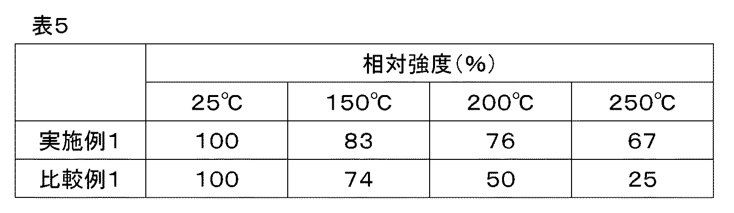
[温度特性(発光強度維持率)]
本実施態様の蛍光体は、温度特性にも優れる。具体的には、450nmの波長の光を照射した場合の、25℃での発光スペクトル図中の発光ピーク強度値に対する200℃での発光スペクトル図中の発光ピーク強度値の割合が、通常50%以上であり、好ましくは60%以上、特に好ましくは70%以上である。
また、通常の蛍光体は温度上昇と共に発光強度が低下するので、該割合が100%を超えることは考えられにくいが、何らかの理由により100%を超えることがあってもよい。ただし100%を超えるようであれば、温度変化により色ずれを起こす傾向がある。
尚、上記温度特性を測定する場合は、常法に従えばよく、例えば、特開2008−138156号公報に記載の方法などが挙げられる。[Temperature characteristics (light emission intensity maintenance rate)]
The phosphor of this embodiment is also excellent in temperature characteristics. Specifically, the ratio of the emission peak intensity value in the emission spectrum diagram at 200 ° C. to the emission peak intensity value in the emission spectrum diagram at 25 ° C. when irradiated with light having a wavelength of 450 nm is usually 50%. The above is preferably 60% or more, and particularly preferably 70% or more.
Further, since the emission intensity of a normal phosphor decreases with increasing temperature, it is unlikely that the ratio exceeds 100%, but it may exceed 100% for some reason. However, if it exceeds 100%, color shift tends to occur due to a temperature change.
When measuring the above temperature characteristics, a conventional method may be followed, and examples thereof include the method described in JP-A-2008-138156.
[励起波長]
本実施態様の蛍光体は、通常300nm以上、好ましくは350nm以上、より好ましくは400nm以上、また、通常500nm以下、好ましくは480nm以下、より好ましくは460nm以下、さらに好ましくは450nm以下の波長範囲に励起ピークを有する。即ち、近紫外から青色領域の光で励起される。[Excitation wavelength]
The phosphor of the present embodiment is usually excited to a wavelength range of 300 nm or more, preferably 350 nm or more, more preferably 400 nm or more, and usually 500 nm or less, preferably 480 nm or less, more preferably 460 nm or less, still more preferably 450 nm or less. Has a peak. That is, it is excited by light in the blue region from near-ultraviolet rays.
[CIE色度座標]
本実施態様の蛍光体におけるCIE色度座標のx値は、通常0.450以上、好ましくは0.475上、より好ましくは0.500以上、さらに好ましくは0.520以上、特に好ましくは0.540以上であり、通常0.660以下、好ましくは0.640以下、より好ましくは0.620以下である。また、本実施態様の蛍光体のCIE色度座標のy値は、通常0.360以上、好ましくは0.380以上であり、通常0.500以下、好ましくは0.480以下、より好ましくは0.460以下である。
CIE色度座標が上記の範囲にあることで、青色LEDと組み合わせて使用する際に、演色性のよい発光色、好ましくは白色〜電球色の発光を示す発光装置が得られる。[CIE chromaticity coordinates]
The x value of the CIE chromaticity coordinates in the phosphor of the present embodiment is usually 0.450 or more, preferably 0.475 or more, more preferably 0.500 or more, still more preferably 0.520 or more, and particularly preferably 0. It is 540 or more, usually 0.660 or less, preferably 0.640 or less, and more preferably 0.620 or less. The y value of the CIE chromaticity coordinates of the phosphor of the present embodiment is usually 0.360 or more, preferably 0.380 or more, usually 0.500 or less, preferably 0.480 or less, more preferably 0. .460 or less.
When the CIE chromaticity coordinates are in the above range, a light emitting device exhibiting a light emitting color having good color rendering properties, preferably white to light bulb color, when used in combination with a blue LED can be obtained.
(量子効率)
本実施形態の蛍光体における外部量子効率(ηo)は、通常40%以上、好ましくは45%以上、更に好ましくは50%以上、特に好ましくは55%以上である。外部量子効率は高いほど発光効率が高くなるため好ましい。
本実施形態の蛍光体における内部量子効率(ηi)は、通常60%以上、好ましくは65%以上、さらに好ましくは70%以上、さらに好ましくは75%以上、特に好ましくは80%以上である。内部量子効率は、蛍光体が吸収した励起光の光子数に対する発光した光子数の比率を意味する。このため内部量子効率が高いほど発光効率や発光強度が高くなるため好ましい。(Quantum efficiency)
The external quantum efficiency (η o ) in the phosphor of the present embodiment is usually 40% or more, preferably 45% or more, more preferably 50% or more, and particularly preferably 55% or more. The higher the external quantum efficiency, the higher the luminous efficiency, which is preferable.
The internal quantum efficiency (η i ) in the phosphor of the present embodiment is usually 60% or more, preferably 65% or more, more preferably 70% or more, still more preferably 75% or more, and particularly preferably 80% or more. The internal quantum efficiency means the ratio of the number of emitted photons to the number of photons of the excitation light absorbed by the phosphor. Therefore, the higher the internal quantum efficiency, the higher the luminous efficiency and the luminous intensity, which is preferable.
[格子定数]
本実施態様の蛍光体の格子定数は、下記の通りである。
a軸が、通常7.11Å以上、好ましくは7.55Å以上、より好ましくは7.87Å以上であり、また通常8.35Å以下、好ましく8.19Å以下、より好ましくは8.03Å以下である。
尚、後述する通り、本実施態様の蛍光体における結晶系は、六方晶系である。その為、b軸は、a軸と同様の範囲である。好ましい態様も同様である。
さらにc軸が、通常13.67Å以上、好ましくは13.96Å以上、より好ましくは14.25Å以上、また通常15.11Å以下、好ましくは14.82Å以下、より好ましくは14.54Å以下である。[Lattice constant]
The lattice constant of the phosphor of this embodiment is as follows.
The a-axis is usually 7.11 Å or more, preferably 7.55 Å or more, more preferably 7.87 Å or more, and usually 8.35 Å or less, preferably 8.19 Å or less, more preferably 8.03 Å or less.
As will be described later, the crystal system in the phosphor of this embodiment is a hexagonal system. Therefore, the b-axis has the same range as the a-axis. The preferred embodiment is similar.
Further, the c-axis is usually 13.67 Å or more, preferably 13.96 Å or more, more preferably 14.25 Å or more, and usually 15.11 Å or less, preferably 14.82 Å or less, more preferably 14.54 Å or less.
[単位格子体積]
本実施態様の蛍光体における、格子定数から算出される単位格子体積(V)は、好ましくは709.36Å3以上、より好ましくは748.77Å3以上であり、更に好ましくは768.47Å3以上、また、好ましくは866.99Å3以下、より好ましくは827.59Å3以下、更に好ましくは807.88Å3以下である。
単位格子体積が大きすぎる、もしくは単位格子体積が小さすぎると骨格構造が不安定化して別の構造の不純物が副生するようになり、発光強度の低下や色純度の低下を招く傾向がある。[Unit cell volume]
In the phosphor of the present embodiment, the unit lattice volume (V) calculated from the lattice constant is preferably 709.36 Å 3 or more, more preferably 748.77 Å 3 or more, and further preferably 768.47 Å 3 or more. Further, it is preferably 866.99 Å 3 or less, more preferably 827.59 Å 3 or less, and further preferably 807.88 Å 3 or less.
If the unit cell volume is too large or the unit cell volume is too small, the skeletal structure becomes unstable and impurities of another structure are by-produced, which tends to cause a decrease in emission intensity and a decrease in color purity.
[結晶系と空間群]
本実施態様の蛍光体における結晶系は、六方晶(Hexagonal)である。
また、本実施態様の蛍光体における空間群は、平均構造が上記長さの繰り返し周期を示していれば特に限定されないが、「International Tables for Crystallography(Third,revised edition),Volume A SPACE−GROUP SYMMETRY」に基づく168番(P6)又は174番(P−6)に属するものであることが好ましく、P−6に属するものが特に好ましい。
ここで、格子定数及び空間群は常法に従って求めることできる。格子定数であれば、X線回折及び中性子線回折の結果をリートベルト(Rietveld)解析して求めることができ、空間群であれば、電子線回折により求めることができる。
尚、このような結晶構造においては、付活元素MはSrのサイトに固溶置換されている状態となる。[Crystal system and space group]
The crystal system in the phosphor of this embodiment is hexagonal.
Further, the space group in the phosphor of the present embodiment is not particularly limited as long as the average structure shows a repetition period of the above length, but "International Tables for Crystallography (Third, Revised edition), Volume A SPACE-GROUP symmetric". It is preferable that it belongs to No. 168 (P6) or No. 174 (P-6) based on "P-6", and it is particularly preferable that it belongs to P-6.
Here, the lattice constant and the space group can be obtained according to a conventional method. If it is a lattice constant, the results of X-ray diffraction and neutron diffraction can be obtained by Rietveld analysis, and if it is a space group, it can be obtained by electron diffraction.
In such a crystal structure, the activating element M is in a state of being solid-solved and substituted at the site of Sr.
[粉末X線回折(XRD)パターン]
本実施態様の蛍光体は、CuKα線(1.5418Å)を用いて測定された粉末X線回折パターンにおいて下記に示す領域1〜5にピークを有する。
尚、領域3には少なくとも2つのピークを有し、そのうちの一つのピークは、粉末X線回折パターンにおいて最も高いピーク強度を有する。これを、最強ピーク強度:Imaxと定義する。ここで、ピーク強度はバックグラウンド補正を行って得た値である。
領域1 12.23°≦2θ≦13.52°
領域2 27.32°≦2θ≦30.00°
領域3 30.07°≦2θ≦35.53°
領域4 35.58°≦2θ≦38.00°
領域5 38.03°≦2θ≦41.37°[Powder X-ray diffraction (XRD) pattern]
The phosphor of this embodiment has peaks in
The
Region 2 27.32 ° ≤ 2θ ≤ 30.00 °
Region 4 35.58 ° ≤ 2θ ≤ 38.00 °
本実施態様において、領域1〜5にピークを有するとは、ピークトップが、領域1〜5の範囲内にあることを意味する。本実施態様において、領域1〜5を特定することの理由は、本実施態様の蛍光体に特徴的なピークを選択したに過ぎない。尚、本実施態様の蛍光体では、結晶の形状によっては測定時に配向してしまい、X線回折パターンで確認できるピーク、確認できなくなってしまうピークが生じることがある。本実施態様における領域2、4、5に現れるピークは、配向しても特徴的に確認しうるピークである。
In this embodiment, having a peak in
本実施態様の蛍光体としては、X線回折や中性子線回折といった回折法により同定される結晶構造において、結晶構造内に層の積み重ねの周期と順序に不整が生じる積層不整が生じるなどの不規則構造を内包し、局所的に構造の乱れた部分を含んでいてもよい。
この積層不整等の有無は単結晶構造解析において、X線回折パターン画像中におけるストリークの有無、もしくはTEM観察などにより確認することができる。このような局所的な不規則構造を有する場合、X線回折にて区別できる範囲内において統計的に考えた平均構造が周期的な繰り返しを示すこととなる。
構造内の局所的な不規則構造の有無は特に限定はされないが、構造内で局所的に不規則構造を有し、構造内での平均化が行われることが好ましい。これは焼成時に生じる元素の揮発などによる組成ズレが、結晶構造内で局所的に不規則構造をとることで緩和、平均化されることにより、本実施態様の蛍光体の相純度が上がり、別の構造の副生も抑えられることから、発光強度が向上し、温度特性が良好になるためである。As the phosphor of the present embodiment, in a crystal structure identified by a diffraction method such as X-ray diffraction or neutron diffraction, irregularities such as irregular stacking in which the cycle and order of stacking layers occur in the crystal structure occur. The structure may be included, and a locally disordered portion may be included.
The presence or absence of such stacking irregularities can be confirmed in the single crystal structure analysis by the presence or absence of streaks in the X-ray diffraction pattern image, TEM observation, or the like. When having such a locally irregular structure, the average structure considered statistically within the range distinguishable by X-ray diffraction shows periodic repetition.
The presence or absence of a locally irregular structure in the structure is not particularly limited, but it is preferable that the structure has a locally irregular structure and averaging is performed in the structure. This is because the compositional deviation due to volatilization of elements that occurs during firing is alleviated and averaged by locally taking an irregular structure in the crystal structure, so that the phase purity of the phosphor of the present embodiment is increased. This is because the by-product of the structure of the above structure is also suppressed, so that the emission intensity is improved and the temperature characteristics are improved.
領域1に有するピークのうち少なくとも一つのピーク強度(I1)は、最強ピーク強度(Imax)に対する比(I1/Imax)で、通常0.02以上、好ましくは0.04以上、さらに好ましくは0.06以上である。
領域2に有するピークのうち少なくとも一つのピーク強度(I2)は、最強ピーク強度(Imax)に対する比(I2/Imax)で、通常0.23以上、好ましくは0.39以上、さらに好ましくは0.62以上である。
領域3に有するピークであって、最強ピーク強度(Imax)を除いたうち、少なくとも一つのピーク強度(I3)は、最強ピーク強度(Imax)に対する比(I3/Imax)で、通常0.6以上、好ましくは0.7以上、さらに好ましくは0.8以上である。
領域4に有するピークのうち少なくとも一つのピーク強度(I4)は、最強ピーク強度(Imax)に対する比(I4/Imax)で、通常0.12以上、好ましくは0.2以上、さらに好ましくは0.32以上の強度である。
領域5に有するピークのうち少なくとも一つのピーク強度(I5)は、最強ピーク強度(Imax)に対する比(I5/Imax)で、通常0.14以上、好ましくは0.23以上、さらに好ましくは0.37以上の強度である。The peak intensity (I 1 ) of at least one of the peaks in the
The peak intensity (I 2 ) of at least one of the peaks in the region 2 is a ratio (I 2 / I max ) to the strongest peak intensity (I max ), which is usually 0.23 or more, preferably 0.39 or more, and further. It is preferably 0.62 or more.
Of the peaks in the
The peak intensity (I 4 ) of at least one of the peaks in the region 4 is a ratio (I 4 / I max ) to the strongest peak intensity (I max ), which is usually 0.12 or more, preferably 0.2 or more, and further. The strength is preferably 0.32 or more.
The peak intensity (I 5 ) of at least one of the peaks in the
<蛍光体の製造方法>
本実施態様の蛍光体を得るための、原料、蛍光体製造法等については以下の通りである。
本実施態様の蛍光体の製造方法は特に制限されないが、例えば、付活元素である元素Mの原料(以下、適宜「M源」という。)、Aの原料(以下、適宜「A源」という。)、Alの原料(以下、適宜「Al源」という。)、Siの原料(以下、適宜「Si源」という)を混合し(混合工程)、得られた混合物を焼成する(焼成工程)ことにより製造することができる。
また、以下では例えば、元素Euの原料を「Eu源」、元素Smの原料を「Sm源」などということがある。<Manufacturing method of phosphor>
The raw materials, the phosphor production method, and the like for obtaining the phosphor of the present embodiment are as follows.
The method for producing the phosphor of the present embodiment is not particularly limited, and for example, the raw material of the element M which is an active element (hereinafter, appropriately referred to as “M source”) and the raw material of A (hereinafter, appropriately referred to as “A source”). ), Al raw material (hereinafter, appropriately referred to as "Al source"), Si raw material (hereinafter, appropriately referred to as "Si source") are mixed (mixing step), and the obtained mixture is fired (burning step). It can be manufactured by.
Further, in the following, for example, the raw material of the element Eu may be referred to as "Eu source", the raw material of the element Sm may be referred to as "Sm source", and the like.
[蛍光体原料]
(M源)
M源のうち、Eu源の具体例としては、Eu2O3、Eu2(SO4)3、Eu2(C2O4)3・10H2O、EuCl2、EuCl3、Eu(NO3)3・6H2O、EuN、EuNH等が挙げられる。中でもEu2O3、EuN等が好ましく、特に好ましくはEuNである。
また、Sm源、Tm源、Yb源等のその他の付活元素の原料の具体例としては、Eu源の具体例として挙げた各化合物において、EuをそれぞれSm、Tm、Yb等に置き換えた化合物が挙げられる。[Fluorescent material]
(M source)
Among the M sources, specific examples of the Eu source include Eu 2 O 3 , Eu 2 (SO 4 ) 3 , Eu 2 (C 2 O 4 ) 3・ 10H 2 O, EuCl 2 , EuCl 3 , and Eu (NO 3). ) 3 · 6H 2 O, EuN , EuNH and the like. Among them, Eu 2 O 3 , EuN and the like are preferable, and EuN is particularly preferable.
Further, as specific examples of raw materials for other active elements such as Sm source, Tm source, Yb source, etc., in each of the compounds mentioned as specific examples of Eu source, Eu is replaced with Sm, Tm, Yb, etc., respectively. Can be mentioned.
(A源)
A源のうち、Sr源の具体例としては、SrO、Sr(OH)2・8H2O、SrCO3、Sr(NO3)2、SrSO4、Sr(C2O4)・H2O、Sr(OCOCH3)2・0.5H2O、SrCl2、Sr3N2、SrNH等が挙げられる。中でも、SrO、SrCO3、Sr2N、Sr3N2が好ましく、Sr2N、Sr3N2が特に好ましい。また、反応性の点から粒径が小さく、発光効率の点から純度の高いものが好ましい。
また、Mg源、Ca源、Ba源などのその他のアルカリ土類金属元素の原料の具体例としては、上記Sr源の具体例として挙げた各化合物において、SrをMg、Ca、Ba等に置き換えた化合物が挙げられる。(Source A)
Of A source, specific examples of Sr source, SrO, Sr (OH) 2 · 8H 2 O,
Further, as a specific example of raw materials for other alkaline earth metal elements such as Mg source, Ca source, and Ba source, Sr is replaced with Mg, Ca, Ba, etc. in each of the compounds mentioned as specific examples of the Sr source. Compounds can be mentioned.
(Al源)
Al源の具体例としては、AlN、Al2O3、Al(OH)3、AlOOH、Al(NO3)3等が挙げられる。中でも、AlN、Al2O3が好ましく、AlNが特に好ましい。また、AlNとして、反応性の点から、粒径が小さく、発光効率の点から純度の高いものが好ましい。
その他の3価の元素の原料の具体例としては、上記Al源の具体例として挙げた各化合物において、AlをB、Ga、In、Sc、Y、La、Gd、Lu等に置き換えた化合物が挙げられる。なお、Al源は、単体のAlを用いてもよい。(Al source)
Specific examples of the Al source include AlN, Al 2 O 3 , Al (OH) 3 , AlOOH, Al (NO 3 ) 3, and the like. Of these, AlN and Al 2 O 3 are preferable, and AlN is particularly preferable. Further, AlN preferably has a small particle size from the viewpoint of reactivity and high purity from the viewpoint of luminous efficiency.
Specific examples of raw materials for other trivalent elements include compounds in which Al is replaced with B, Ga, In, Sc, Y, La, Gd, Lu, etc. in each of the compounds mentioned as specific examples of the Al source. Can be mentioned. As the Al source, a single Al may be used.
(Si源)
Si源の具体例としては、SiO2又はSi3N4を用いるのが好ましい。また、SiO2となる化合物を用いることもできる。このような化合物としては、具体的には、SiO2、H4SiO4、Si(OCOCH3)4等が挙げられる。また、Si3N4として反応性の点から、粒径が小さく、発光効率の点から純度の高いものが好ましい。さらに、不純物である炭素元素の含有割合が少ないものの方が好ましい。
その他の4価の元素の原料の具体例としては、上記Si源の具体例として挙げた各化合物において、SiをそれぞれGe、Ti、Zr、Hf等に置き換えた化合物が挙げられる。なお、Si源は、単体のSiを用いてもよい。(Si source)
As a specific example of the Si source, it is preferable to use SiO 2 or Si 3 N 4 . Further, a compound that becomes SiO 2 can also be used. Specific examples of such a compound include SiO 2 , H 4 SiO 4 , Si (OCOCH 3 ) 4, and the like. Further, Si 3 N 4 preferably has a small particle size from the viewpoint of reactivity and high purity from the viewpoint of luminous efficiency. Further, it is preferable that the content ratio of the carbon element which is an impurity is small.
Specific examples of raw materials for other tetravalent elements include compounds in which Si is replaced with Ge, Ti, Zr, Hf, etc. in each of the compounds mentioned as specific examples of the Si source. As the Si source, a single Si may be used.
なお、上述したM源、A源、Al源及びSi源は、それぞれ、一種のみを用いてもよく、二種以上を任意の組み合わせ及び比率で併用してもよい。 As the above-mentioned M source, A source, Al source and Si source, only one type may be used, or two or more types may be used in any combination and ratio.
[混合工程]
目的組成が得られるように蛍光体原料を秤量し、ボールミル等を用いて十分混合したのち、ルツボに充填し、所定温度、雰囲気下で焼成し、焼成物を粉砕、洗浄することにより、本実施態様の蛍光体を得ることができる。[Mixing process]
The fluorophore material is weighed so that the desired composition can be obtained, mixed sufficiently using a ball mill or the like, filled in a crucible, fired at a predetermined temperature and atmosphere, and the fired product is crushed and washed. A form of phosphor can be obtained.
上記混合手法としては、特に限定はされず、乾式混合法や湿式混合法のいずれであってもよい。
乾式混合法としては、例えば、ボールミルなどが挙げられる。
湿式混合法としては、例えば、前述の蛍光体原料に水等の溶媒又は分散媒を加え、乳鉢と乳棒、を用いて混合し、溶液又はスラリーの状態とした上で、噴霧乾燥、加熱乾燥、又は自然乾燥等により乾燥させる方法である。The mixing method is not particularly limited, and may be either a dry mixing method or a wet mixing method.
Examples of the dry mixing method include a ball mill and the like.
As a wet mixing method, for example, a solvent such as water or a dispersion medium is added to the above-mentioned fluorescent material, and the mixture is mixed using a dairy pot and a dairy stick to prepare a solution or a slurry, and then spray-dried or heat-dried. Alternatively, it is a method of drying by natural drying or the like.
[焼成工程]
得られた混合物を、各蛍光体原料と反応性の低い材料からなるルツボ又はトレイ等の耐熱容器中に充填する。このような焼成時に用いる耐熱容器の材質としては、本実施態様の効果を損なわない限り特に制限はないが、例えば、窒化ホウ素などの坩堝が挙げられる。[Baking process]
The obtained mixture is filled in a heat-resistant container such as a crucible or a tray made of a material having low reactivity with each phosphor raw material. The material of the heat-resistant container used at the time of firing is not particularly limited as long as the effect of the present embodiment is not impaired, and examples thereof include a crucible such as boron nitride.
焼成温度は、圧力など、その他の条件によっても異なるが、通常1800℃以上、2150℃以下の温度範囲で焼成を行なうことができる。焼成工程における最高到達温度としては、通常1800℃以上、好ましくは1900℃以上、より好ましくは2000℃以上、また、通常2150℃以下、好ましくは2100℃以下である。
焼成温度が高すぎると窒素が飛んで母体結晶に欠陥を生成し着色する傾向にあり、低すぎると固相反応の進行が遅くなる傾向にあり、目的相を主相として得にくくなる場合がある。The firing temperature varies depending on other conditions such as pressure, but usually firing can be performed in a temperature range of 1800 ° C. or higher and 2150 ° C. or lower. The maximum temperature reached in the firing step is usually 1800 ° C. or higher, preferably 1900 ° C. or higher, more preferably 2000 ° C. or higher, and usually 2150 ° C. or lower, preferably 2100 ° C. or lower.
If the calcination temperature is too high, nitrogen tends to fly away and defects are generated in the matrix crystal, which tends to color the matrix crystal. ..
焼成工程時の圧力は、焼成温度等によっても異なるが、通常0.2MPa以上、好ましくは0.4MPa以上であり、また、通常200MPa以下、好ましくは190MPa以下である。構成している元素、特にアルカリ土類金属元素の揮発を抑え、欠陥が生じるのを抑える場合は0.8MPa以上が好ましく、さらに10MPa以上が好ましく、さらに50MPa以上が好ましく、さらに100MPa以上が好ましく、特に150MPa以上が好ましい。また、吸収効率の高い蛍光体を得たい場合は190MPa以下が好ましく、さらに50MPa以下が好ましく、さらに10MPa以下が好ましく、特に1.0MPa以下が好ましい。 The pressure during the firing step varies depending on the firing temperature and the like, but is usually 0.2 MPa or more, preferably 0.4 MPa or more, and usually 200 MPa or less, preferably 190 MPa or less. When the volatilization of the constituent elements, particularly alkaline earth metal elements, is suppressed and the occurrence of defects is suppressed, 0.8 MPa or more is preferable, 10 MPa or more is preferable, 50 MPa or more is more preferable, and 100 MPa or more is further preferable. In particular, 150 MPa or more is preferable. Further, when it is desired to obtain a phosphor having high absorption efficiency, it is preferably 190 MPa or less, more preferably 50 MPa or less, further preferably 10 MPa or less, and particularly preferably 1.0 MPa or less.
焼成工程における圧力が10MPa以下で焼成する場合は焼成時の最高到達温度は、通常1800℃以上、好ましくは1900℃以上、より好ましく2000℃以上であり、また、通常2150℃以下、好ましくは2100℃以下である。
焼成温度が1900℃未満であると固相反応が進まないため不純物相もしくは未反応相のみが出現し、目的相を主相として得にくくなる場合がある。When firing at a pressure of 10 MPa or less in the firing step, the maximum temperature reached during firing is usually 1800 ° C. or higher, preferably 1900 ° C. or higher, more preferably 2000 ° C. or higher, and usually 2150 ° C. or lower, preferably 2100 ° C. It is as follows.
If the calcination temperature is less than 1900 ° C., the solid-phase reaction does not proceed, so that only the impurity phase or the unreacted phase appears, and it may be difficult to obtain the target phase as the main phase.
また、ごくわずかに目的の結晶相が得られたとしても、結晶内では発光中心となる元素、特にEu元素の拡散がされず量子効率を低下させる可能性がある。また、焼成温度が高すぎると目的の蛍光体結晶を構成する元素が揮発しやすくなり、格子欠陥を形成、もしくは分解し別の相が不純物として生じてしまう可能性が高い。 Further, even if a very small amount of the desired crystal phase is obtained, the element that is the center of light emission, particularly the Eu element, is not diffused in the crystal, and the quantum efficiency may be lowered. Further, if the firing temperature is too high, the elements constituting the target phosphor crystal are likely to volatilize, and there is a high possibility that lattice defects are formed or decomposed to generate another phase as impurities.
焼成工程における焼成雰囲気は、本実施態様の蛍光体が得られる限り任意であるが、窒素含有雰囲気とすることが好ましい。具体的には、窒素雰囲気、水素含有窒素雰囲気等が挙げられ、中でも窒素雰囲気が好ましい。なお、焼成雰囲気の酸素含有量は、通常10ppm以下、好ましくは5ppm以下である。 The firing atmosphere in the firing step is arbitrary as long as the phosphor of the present embodiment can be obtained, but a nitrogen-containing atmosphere is preferable. Specific examples thereof include a nitrogen atmosphere and a hydrogen-containing nitrogen atmosphere, and the nitrogen atmosphere is particularly preferable. The oxygen content of the firing atmosphere is usually 10 ppm or less, preferably 5 ppm or less.
焼成時間は、焼成時の温度や圧力等によっても異なるが、通常10分間以上、好ましくは30分間以上、また、通常72時間以下、好ましくは12時間以下である。焼成時間が短すぎると粒生成と粒成長を促すことができないため、特性のよい蛍光体を得ることができず、焼成時間が長すぎると構成している元素の揮発が促されるため、原子欠損により結晶構造内に欠陥が誘発され特性のよい蛍光体を得ることができない。 The firing time varies depending on the temperature and pressure at the time of firing, but is usually 10 minutes or more, preferably 30 minutes or more, and usually 72 hours or less, preferably 12 hours or less. If the firing time is too short, grain formation and grain growth cannot be promoted, so that a phosphor having good characteristics cannot be obtained, and if the firing time is too long, volatilization of the constituent elements is promoted, resulting in atomic defects. As a result, defects are induced in the crystal structure, and a phosphor having good characteristics cannot be obtained.
[後処理工程]
得られる焼成物は、粒状又は塊状となる。これを解砕、粉砕及び/又は分級操作を組み合わせて所定のサイズの粉末にする。ここでは、D50が約30μm以下になるように処理するとよい。
具体的な処理の例としては、合成物を目開き45μm程度の篩分級処理し、篩を通過した粉末を次工程に回す方法、或いは合成物をボールミルや振動ミル、ジェットミル等の一般的な粉砕機を使用して所定の粒度に粉砕する方法が挙げられる。後者の方法において、過度の粉砕は、光を散乱しやすい微粒子を生成するだけでなく、粒子表面に結晶欠陥を生成し、発光効率の低下を引き起こす可能性がある。[Post-treatment process]
The resulting fired product is granular or lumpy. This is combined with crushing, crushing and / or classification operations into a powder of a predetermined size. Here, it is advisable to process so that D50 is about 30 μm or less.
Specific examples of the treatment include a method in which the composite is sieve-classified with an opening of about 45 μm and the powder that has passed through the sieve is passed to the next step, or the composite is generally used in a ball mill, vibration mill, jet mill, or the like. Examples thereof include a method of pulverizing to a predetermined particle size using a pulverizer. In the latter method, excessive pulverization not only produces fine particles that easily scatter light, but also creates crystal defects on the particle surface, which may cause a decrease in luminous efficiency.
また、必要に応じて、蛍光体(焼成物)を洗浄する工程を設けてもよい。洗浄工程後は、蛍光体を付着水分がなくなるまで乾燥させて、使用に供する。さらに、必要に応じて、凝集をほぐすために分散・分級処理を行ってもよい。
尚、本実施態様の蛍光体は、あらかじめ構成金属元素を合金化して、それを窒化して形成する、所謂、合金法で形成してもよい。Further, if necessary, a step of cleaning the phosphor (fired product) may be provided. After the washing step, the phosphor is dried until there is no adhering water and is used. Further, if necessary, dispersion / classification treatment may be performed to loosen the agglomeration.
The phosphor of the present embodiment may be formed by a so-called alloying method in which a constituent metal element is alloyed in advance and then nitrided to form the phosphor.
<第一の発明における一実施態様:蛍光体含有組成物>
本発明の第一の発明における第一の実施態様に係る蛍光体は、液体媒体と混合して用いることもできる。特に、本発明の第一の発明における第一の実施態様に係る蛍光体を発光装置等の用途に使用する場合には、これを液体媒体中に分散させた形態で用いることが好ましい。本発明の第一の発明における第一の実施態様に係る蛍光体を液体媒体中に分散させたものを、本発明の第一の発明における一実施態様として、適宜「本発明の第一の発明における一実施態様に係る蛍光体含有組成物」などと呼ぶものとする。<One Embodiment in the First Invention: Fluorescent Body-Containing Composition>
The phosphor according to the first embodiment of the first invention of the present invention can also be used by mixing with a liquid medium. In particular, when the phosphor according to the first embodiment of the first invention of the present invention is used for an application such as a light emitting device, it is preferable to use the phosphor in a form dispersed in a liquid medium. The phosphor according to the first embodiment of the first invention of the present invention is dispersed in a liquid medium, as one embodiment of the first invention of the present invention, as appropriate, "the first invention of the present invention". It shall be referred to as "a fluorescent substance-containing composition according to one embodiment of the above".
[蛍光体]
本実施態様の蛍光体含有組成物に含有させる本発明の第一の発明における第一の実施態様に係る蛍光体の種類に制限は無く、上述したものから任意に選択することができる。また、本実施態様の蛍光体含有組成物に含有させる本発明の第一の発明における第一の実施態様に係る蛍光体は、1種のみであってもよく、2種以上を任意の組み合わせ及び比率で併用してもよい。更に、本実施態様の蛍光体含有組成物には、本実施態様の効果を著しく損なわない限り、本発明の第一の発明における第一の実施態様に係る蛍光体以外の蛍光体を含有させてもよい。[Fluorescent material]
There is no limitation on the type of the phosphor according to the first embodiment of the first invention of the present invention to be contained in the phosphor-containing composition of the present embodiment, and any of the above can be selected. Further, the phosphor according to the first embodiment of the first invention of the present invention to be contained in the phosphor-containing composition of the present embodiment may be only one kind, and any combination of two or more kinds and It may be used together in a ratio. Further, the fluorescent substance-containing composition of the present embodiment contains a fluorescent substance other than the fluorescent substance according to the first embodiment of the first invention of the present invention, as long as the effect of the present embodiment is not significantly impaired. May be good.
[液体媒体]
本実施態様の蛍光体含有組成物に使用される液体媒体としては、該蛍光体の性能を目的の範囲で損なわない限りにおいて特に限定されない。例えば、所望の使用条件下において液状の性質を示し、本発明の第一の発明における第一の実施態様に係る蛍光体を好適に分散させるとともに、好ましくない反応を生じないものであれば、任意の無機系材料及び/又は有機系材料が使用でき、例えば、シリコーン樹脂、エポキシ樹脂、ポリイミドシリコーン樹脂などが挙げられる。[Liquid medium]
The liquid medium used in the fluorescent substance-containing composition of the present embodiment is not particularly limited as long as the performance of the fluorescent substance is not impaired within a target range. For example, any one as long as it exhibits liquid properties under desired conditions of use, preferably disperses the phosphor according to the first embodiment of the first invention of the present invention, and does not cause an undesired reaction Inorganic and / or organic materials can be used, and examples thereof include silicone resin, epoxy resin, and polyimide silicone resin.
[液体媒体及び蛍光体の含有率]
本実施態様の蛍光体含有組成物中の蛍光体及び液体媒体の含有率は、本実施態様の効果を著しく損なわない限り任意であるが、液体媒体については、本実施態様の蛍光体含有組成物全体に対して、通常50重量%以上、好ましくは75重量%以上であり、通常99重量%以下、好ましくは95重量%以下である。[Liquid medium and phosphor content]
The content of the phosphor and the liquid medium in the fluorophore-containing composition of the present embodiment is arbitrary as long as the effect of the present embodiment is not significantly impaired, but for the liquid medium, the fluorophore-containing composition of the present embodiment It is usually 50% by weight or more, preferably 75% by weight or more, and usually 99% by weight or less, preferably 95% by weight or less, based on the whole.
[その他の成分]
なお、本実施態様の蛍光体含有組成物には、本実施態様の効果を著しく損なわない限り、蛍光体及び液体媒体以外に、その他の成分を含有させてもよい。また、その他の成分は、1種のみを用いてもよく、2種以上を任意の組み合わせ及び比率で併用してもよい。[Other ingredients]
The fluorescent substance-containing composition of the present embodiment may contain other components in addition to the fluorescent substance and the liquid medium as long as the effects of the present embodiment are not significantly impaired. Further, as the other components, only one kind may be used, or two or more kinds may be used in any combination and ratio.
<1−2.第一の発明における第二の実施態様:発光装置>
本発明の第一の発明における第二の実施態様は、第1の発光体(励起光源)と、当該第1の発光体からの光の照射によって可視光を発する第2の発光体とを有する発光装置であって、該第2の発光体として本発明の第一の発明における第一の実施態様に係る蛍光体を含有するものである。ここで、本発明の第一の発明における第一の実施態様に係る蛍光体は、何れか1種を単独で使用してもよく、2種以上を任意の組み合わせ及び比率で併用してもよい。<1-2. Second embodiment in the first invention: light emitting device>
A second embodiment of the first invention of the present invention has a first illuminant (excitation light source) and a second illuminant that emits visible light when irradiated with light from the first illuminant. It is a light emitting device and contains the phosphor according to the first embodiment in the first invention of the present invention as the second light emitting body. Here, as the phosphor according to the first embodiment of the first invention of the present invention, any one type may be used alone, or two or more types may be used in combination in any combination and ratio. ..
本実施態様における蛍光体としては、例えば、励起光源からの光の照射下において、黄色ないし橙色領域の蛍光を発する蛍光体を使用する。具体的には、発光装置を構成する場合、黄色ないし橙色蛍光体としては、560nm〜620nmの波長範囲に発光ピークを有するものが好ましい。
尚、励起源については、420nm未満の波長範囲に発光ピークを有するものを用いてもよい。As the phosphor in this embodiment, for example, a phosphor that emits fluorescence in the yellow to orange region under irradiation with light from an excitation light source is used. Specifically, when constructing a light emitting device, the yellow to orange phosphor having a light emitting peak in the wavelength range of 560 nm to 620 nm is preferable.
As the excitation source, a source having an emission peak in a wavelength range of less than 420 nm may be used.
以下、本発明の第一の発明における第一の実施態様に係る蛍光体が、560nm以上620nm以下の波長範囲に発光ピークを有し、且つ第一の発光体が420nm以上500nm以下の波長範囲に発光ピークを有するものを用いる場合の発光装置の態様について記載するが、本実施態様はこれらに限定されるものではない。 Hereinafter, the phosphor according to the first embodiment of the first invention of the present invention has an emission peak in a wavelength range of 560 nm or more and 620 nm or less, and the first illuminant has a wavelength range of 420 nm or more and 500 nm or less. A mode of a light emitting device in the case of using a device having a light emitting peak will be described, but the present embodiment is not limited thereto.
上記の場合、本実施態様の発光装置は、例えば、次の(A)又は(B)の態様とすることができる。
(A)第1の発光体として、350nm以上450nm以下の波長範囲に発光ピークを有するものを用い、第2の発光体の第1の蛍光体として、本発明の第一の発明における第一の実施態様に係る蛍光体を用いる態様。
(B)第1の発光体として、350nm以上450nm以下の波長範囲に発光ピークを有するものを用い、第2の発光体の第1の蛍光体として、620nmより大きく700nm未満の波長範囲に発光ピークを有する少なくとも1種の蛍光体(赤色蛍光体)を用い、第2の発光体の第2の蛍光体として、本発明の第一の発明における第一の実施態様に係る蛍光体を用いる態様。In the above case, the light emitting device of this embodiment can be, for example, the following aspect (A) or (B).
(A) As the first illuminant, one having an emission peak in the wavelength range of 350 nm or more and 450 nm or less is used, and as the first phosphor of the second illuminant, the first in the first invention of the present invention. A mode in which a phosphor according to an embodiment is used.
(B) As the first light emitter, one having an emission peak in the wavelength range of 350 nm or more and 450 nm or less is used, and as the first phosphor of the second light emitter, the emission peak is larger than 620 nm and less than 700 nm. An embodiment in which at least one fluorescent substance (red fluorescent substance) having the above is used, and the fluorescent substance according to the first embodiment of the first invention of the present invention is used as the second fluorescent substance of the second light emitting body.
(赤色蛍光体)
上記の態様における赤色蛍光体としては、例えば、下記の蛍光体が好適に用いられる。
Mn付活フッ化物蛍光体としては、例えば、K2(Si,Ti)F6:Mn、K2Si1−xNaxAlxF6:Mn(0<x<1)、
硫化物蛍光体としては、例えば、(Sr,Ca)S:Eu(CAS蛍光体)、La2O2S:Eu(LOS蛍光体)、
ガーネット系蛍光体としては、例えば、(Y,Lu,Gd,Tb)3Mg2AlSi2O12:Ce、
ナノ粒子としては、例えば、CdSe、
窒化物または酸窒化物蛍光体としては、例えば、(Sr,Ca)AlSiN3:Eu(S/CASN蛍光体)、(CaAlSiN3)1−x・(SiO2N2)x:Eu(CASON蛍光体)、(La,Ca)3(Al,Si)6N11:Eu(LSN蛍光体)、(Ca,Sr,Ba)2Si5(N,O)8:Eu(258蛍光体)、(Sr,Ca)Al1+xSi4−xOxN7−x:Eu(1147蛍光体)、Mx(Si,Al)12(O,N)16:Eu(Mは、Ca、Srなど)(αサイアロン蛍光体)、Li(Sr,Ba)Al3N4:Eu(上記のxは、いずれも0<x<1)
などが挙げられる。(Red phosphor)
As the red phosphor in the above embodiment, for example, the following phosphor is preferably used.
Examples of the active fluoride phosphor with Mn include K 2 (Si, Ti) F 6 : Mn, K 2 Si 1-x Na x Al x F 6 : Mn (0 <x <1),
Examples of the sulfide phosphor include (Sr, Ca) S: Eu (CAS phosphor), La 2 O 2 S: Eu (LOS phosphor), and the like.
Examples of the garnet-based phosphor include (Y, Lu, Gd, Tb) 3 Mg 2 AlSi 2 O 12 : Ce,
Examples of nanoparticles include CdSe,
Examples of the nitride or oxynitride phosphor include (Sr, Ca) AlSiN 3 : Eu (S / CASN phosphor), (CaAlSiN 3 ) 1-x · (SiO 2 N 2 ) x : Eu (CASON fluorescence). Body), (La, Ca) 3 (Al, Si) 6 N 11 : Eu (LSN fluorophore), (Ca, Sr, Ba) 2 Si 5 (N, O) 8 : Eu (258 phosphor), ( Sr, Ca) Al 1 + x Si 4-x O x N 7-x : Eu (1147 phosphor), M x (Si, Al) 12 (O, N) 16 : Eu (M is Ca, Sr, etc.) ( α-sialon phosphor), Li (Sr, Ba) Al 3 N 4 : Eu (where x above is 0 <x <1)
And so on.
(黄色蛍光体)
上記の態様において、必要に応じて、本発明の第一の発明における第一の実施態様に係る蛍光体以外に、550〜600nmの範囲発光ピークを有する蛍光体(黄色蛍光体)を用いてもよい。
黄色蛍光体としては、例えば、下記の蛍光体が好適に用いられる。
ガーネット系蛍光体としては、例えば、(Y,Gd,Lu,Tb,La)3(Al,Ga)5O12:(Ce,Eu,Nd)、
オルソシリケートとしては、例えば、(Ba,Sr,Ca,Mg)2SiO4:(Eu,Ce)、
(酸)窒化物蛍光体としては、例えば、(Ba,Ca,Mg)Si2O2N2:Eu(SION系蛍光体)、(Li,Ca)2(Si,Al)12(O,N)16:(Ce,Eu)(α−サイアロン蛍光体)、(Ca,Sr)AlSi4(O,N)7:(Ce,Eu)(1147蛍光体)、(La,Ca,Y)3(Al,Si)6N11:Ce(LSN蛍光体)
などが挙げられる。
尚、上記蛍光体においては、ガーネット系蛍光体が好ましく、中でも、Y3Al5O12:Ceで表されるYAG系蛍光体が最も好ましい。(Yellow phosphor)
In the above embodiment, if necessary, a phosphor (yellow phosphor) having an emission peak in the range of 550 to 600 nm may be used in addition to the phosphor according to the first embodiment of the first invention of the present invention. Good.
As the yellow phosphor, for example, the following phosphors are preferably used.
Examples of the garnet-based phosphor include (Y, Gd, Lu, Tb, La) 3 (Al, Ga) 5 O 12 :( Ce, Eu, Nd),
Examples of the orthosilicate include (Ba, Sr, Ca, Mg) 2 SiO 4 : (Eu, Ce),
Examples of the (acid) nitride phosphor include (Ba, Ca, Mg) Si 2 O 2 N 2 : Eu (SION-based phosphor), (Li, Ca) 2 (Si, Al) 12 (O, N). ) 16 : (Ce, Eu) (α-sialon fluorescent material), (Ca, Sr) AlSi 4 (O, N) 7 : (Ce, Eu) (1147 fluorescent material), (La, Ca, Y) 3 ( Al, Si) 6 N 11 : Ce (LSN phosphor)
And so on.
In the above phosphor, a garnet-based phosphor is preferable,, Y 3 Al 5 O 12: YAG -based phosphor represented by Ce is most preferred.
[発光装置の構成]
本実施態様の発光装置は、第1の発光体(励起光源)を有し、且つ、第2の発光体として少なくとも本発明の第一の発明における第一の実施態様に係る蛍光体を使用している他は、その構成は制限されず、公知の装置構成を任意にとることが可能である。
装置構成及び発光装置の実施形態としては、例えば、特開2007−291352号公報に記載のものが挙げられる。
その他、発光装置の形態としては、砲弾型、カップ型、チップオンボード、リモートフォスファー等が挙げられる。[Configuration of light emitting device]
The light emitting device of the present embodiment has a first light emitting body (excitation light source), and uses at least the phosphor according to the first embodiment of the first invention of the present invention as the second light emitting body. Other than the above, the configuration is not limited, and a known device configuration can be arbitrarily adopted.
Examples of the device configuration and the embodiment of the light emitting device include those described in JP-A-2007-291352.
Other forms of the light emitting device include a cannonball type, a cup type, a chip-on-board type, a remote phosphor, and the like.
[発光装置の用途]
本発明の第一の発明における第二の実施態様に係る発光装置の用途は特に制限されず、通常の発光装置が用いられる各種の分野に使用することが可能であるが、色再現範囲が広く、且つ、演色性も高いことから、中でも照明装置や画像表示装置の光源として、とりわけ好適に用いられる。[Use of light emitting device]
The application of the light emitting device according to the second embodiment of the first invention of the present invention is not particularly limited, and it can be used in various fields in which a normal light emitting device is used, but the color reproduction range is wide. Moreover, since it has high color rendering properties, it is particularly preferably used as a light source for a lighting device or an image display device.
<1−3.第一の発明における第三の実施態様:照明装置>
本発明の第一の発明における第三の実施態様は、本発明の第一の発明における第二の実施態様に係る発光装置を光源として備えることを特徴とする照明装置である。
本発明の第一の発明における第二の実施態様に係る発光装置を照明装置に適用する場合には、前述のような発光装置を公知の照明装置に適宜組み込んで用いればよい。例えば、保持ケースの底面に多数の発光装置を並べた面発光照明装置等を挙げることができる。<1-3. Third Embodiment in the first invention: Lighting device>
A third embodiment of the first invention of the present invention is a lighting device including a light emitting device according to a second embodiment of the first invention of the present invention as a light source.
When the light emitting device according to the second embodiment of the first invention of the present invention is applied to a lighting device, the above-mentioned light emitting device may be appropriately incorporated into a known lighting device. For example, a surface emitting illumination device in which a large number of light emitting devices are arranged on the bottom surface of the holding case can be mentioned.
<1−4.第一の発明における第四の実施態様:画像表示装置>
本発明の第一の発明における第四の実施態様は、本発明の第一の発明における第二の実施態様に係る発光装置を光源として備えることを特徴とする画像表示装置である。
本発明の第一の発明における第二の実施態様に係る発光装置を画像表示装置の光源として用いる場合には、その画像表示装置の具体的構成に制限は無いが、カラーフィルターとともに用いることが好ましい。例えば、画像表示装置として、カラー液晶表示素子を利用したカラー画像表示装置とする場合は、上記発光装置をバックライトとし、液晶を利用した光シャッターと赤、緑、青の画素を有するカラーフィルターとを組み合わせることにより画像表示装置を形成することができる。<1-4. Fourth Embodiment in the First Invention: Image Display Device>
A fourth embodiment of the first invention of the present invention is an image display device including a light emitting device according to a second embodiment of the first invention of the present invention as a light source.
When the light emitting device according to the second embodiment of the first invention of the present invention is used as a light source of the image display device, the specific configuration of the image display device is not limited, but it is preferably used together with the color filter. .. For example, in the case of a color image display device using a color liquid crystal display element as the image display device, the light emitting device is used as a backlight, an optical shutter using a liquid crystal, and a color filter having red, green, and blue pixels. An image display device can be formed by combining the above.
<2.第二の発明>
本発明の第二の発明は、第一の実施態様である蛍光体、第二の実施態様である発光装置、第三の実施態様である照明装置、第四の実施態様である画像表示装置を含む。なお、本発明の第二の発明は、上述した本発明の第一の発明の好ましい態様でもある。<2. Second invention>
The second invention of the present invention comprises a phosphor according to a first embodiment, a light emitting device according to a second embodiment, a lighting device according to a third embodiment, and an image display device according to a fourth embodiment. Including. The second invention of the present invention is also a preferred embodiment of the first invention of the present invention described above.
<2−1.第二の発明における第一の実施態様:蛍光体>
<蛍光体について>
本発明の第二の発明における第一の実施態様に係る蛍光体は、元素M、A、Al、Si、Nを含む結晶相で且つその空間群がP−6である。但し、Mは、付活元素を表し、Aは、アルカリ土類金属元素からなる群から選ばれる1種以上の元素を表す。
この他、本実施態様に係る蛍光体の特性等は、<1−1.第一の発明における第一の実施態様:蛍光体>の記載が適用される。<2-1. First Embodiment in the Second Invention: Fluorescent Material>
<About phosphors>
The phosphor according to the first embodiment of the second invention of the present invention is a crystal phase containing elements M, A, Al, Si, and N, and its space group is P-6. However, M represents an activating element, and A represents one or more elements selected from the group consisting of alkaline earth metal elements.
In addition, the characteristics of the phosphor according to this embodiment are described in <1-1. The description of the first embodiment in the first invention: Fluorescent material> applies.
<第二の発明における一実施態様:蛍光体含有組成物>
本発明の第二の発明における一実施態様である蛍光体含有組成物については、<第一の発明における一実施態様:蛍光体含有組成物>の記載が適用される。<One Embodiment in the Second Invention: Fluorescent Body-Containing Composition>
The description of <one embodiment in the first invention: a fluorescent substance-containing composition> is applied to the fluorescent substance-containing composition according to the second embodiment of the present invention.
<2−2.第二の発明における第一の実施態様:発光装置>
本発明の第二の発明における第一の実施態様である発光装置については、<1−2.第一の発明における第二の実施態様:発光装置>の記載が適用される。<2-2. First Embodiment in the Second Invention: Light Emitting Device>
Regarding the light emitting device according to the first embodiment of the second invention of the present invention, <1-2. The description of the second embodiment of the first invention: light emitting device> applies.
<2−3.第二の発明における第三の実施態様:照明装置>
本発明の第二の発明における第三の実施態様である照明装置については、<1−3.第一の発明における第三の実施態様:照明装置>の記載が適用される。<2-3. Third Embodiment in the second invention: Lighting device>
Regarding the lighting device according to the third embodiment of the second invention of the present invention, <1-3. The description of the third embodiment: lighting device> in the first invention applies.
<2−4.第二の発明における第四の実施態様:画像表示装置>
本発明の第二の発明における第四の実施態様である画像表示装置については、<1−4.第一の発明における第四の実施態様:画像表示装置>の記載が適用される。<2-4. Fourth Embodiment in the Second Invention: Image Display Device>
Regarding the image display device according to the fourth embodiment of the second invention of the present invention, <1-4. The description of the fourth embodiment of the first invention: image display device> is applied.
以下、本発明を実施例によりさらに具体的に説明するが、本発明はその要旨を逸脱しない限り、下記の実施例に限定されるものではない。なお、本実施例は、本発明の第一の発明および第二の発明に共通する実施例である。 Hereinafter, the present invention will be described in more detail with reference to Examples, but the present invention is not limited to the following Examples as long as it does not deviate from the gist thereof. In addition, this Example is an Example common to the 1st invention and the 2nd invention of this invention.
<測定方法>
[発光特性]
試料を銅製試料ホルダーに詰め、蛍光分光光度計FP−6500(JASCO社製)を用いて励起発光スペクトルと発光スペクトルを測定した。なお、測定時には、受光側分光器のスリット幅を1nmに設定して測定を行った。また、発光ピーク波長(以下、「ピーク波長」と称することがある。)と発光ピークの半値幅は、得られた発光スペクトルから読み取った。<Measurement method>
[Light emission characteristics]
The sample was packed in a copper sample holder, and the excitation emission spectrum and the emission spectrum were measured using a fluorescence spectrophotometer FP-6500 (manufactured by JASCO). At the time of measurement, the slit width of the light receiving side spectroscope was set to 1 nm. Further, the emission peak wavelength (hereinafter, may be referred to as “peak wavelength”) and the half width of the emission peak were read from the obtained emission spectrum.
[色度座標]
x、y表色系(CIE 1931表色系)の色度座標は、上述の方法で得られた発光スペクトルの360nm〜800nmの波長領域のデータから、JIS Z8724に準じた方法で、JIS Z8701で規定されるXYZ表色系における色度座標CIExとCIEyとして算出した。[Saturation coordinates]
The chromaticity coordinates of the x and y color systems (CIE 1931 color system) are based on the data in the wavelength region of 360 nm to 800 nm of the emission spectrum obtained by the above method, in accordance with JIS Z8724, in JIS Z8701. It was calculated as the chromaticity coordinates CIEx and CIEy in the defined XYZ color system.
[内部量子効率(ηi)、外部量子効率(ηo)及び吸収効率(αq)]
測定対象となる蛍光体サンプルを、測定精度が保たれるように、十分に表面を平滑にしてセルに詰めて積分球に取り付けた。
この積分球に蛍光体を励起するための発光光源(150WのXeランプ)から光ファイバーを用いて光を導入した。前記の発光光源からの光の発光ピーク波長を405nmの単色光となるようにモノクロメーター(回折格子分光器)等を用いて調整した。この単色光を励起光として、測定対象の蛍光体サンプルに照射し、分光測定装置MCPD7000(大塚電子社製)を用いて、蛍光体サンプルの発光(蛍光)および反射光についてスペクトルを測定した。積分球内の光は、光ファイバーを用いて分光測定装置に導いた。
吸収効率αqは、蛍光体サンプルによって吸収された励起光のフォトン数Nabsを励起光の全フォトン数Nで割った値である。
まず、後者の励起光の全フォトン数Nは、下記(式A)で求められる数値に比例する。そこで、励起光に対してほぼ100%の反射率Rを持つ反射板であるLabsphere社製「Spectralon」(波長450nmの励起光に対して99%の反射率Rを持つ。)を、測定対象として、蛍光体サンプルと同様の配置で上述の積分球に取り付け、励起光を照射し、分光測定装置で測定することにより反射スペクトルIref(λ)を測定し、下記(式A)の値を求めた。[Internal quantum efficiency (η i ), external quantum efficiency (η o ) and absorption efficiency (α q )]
The phosphor sample to be measured was packed in a cell with a sufficiently smooth surface and attached to an integrating sphere so that the measurement accuracy was maintained.
Light was introduced into this integrating sphere using an optical fiber from a light emitting light source (150 W Xe lamp) for exciting a phosphor. The emission peak wavelength of the light from the emission light source was adjusted by using a monochromator (diffraction grating spectroscope) or the like so as to be monochromatic light of 405 nm. This monochromatic light was used as excitation light to irradiate the phosphor sample to be measured, and the spectrum was measured for the emission (fluorescence) and reflected light of the phosphor sample using a spectroscopic measuring device MCPD7000 (manufactured by Otsuka Denshi Co., Ltd.). The light in the integrating sphere was guided to the spectroscopic measuring device using an optical fiber.
The absorption efficiency α q is a value obtained by dividing the number of photons Nabs of the excitation light absorbed by the phosphor sample by the total number N of photons of the excitation light.
First, the total number of photons N of the latter excitation light is proportional to the numerical value obtained by the following (formula A). Therefore, "Spectralon" manufactured by Labsphere (which has a reflectance R of 99% with respect to excitation light having a wavelength of 450 nm), which is a reflector having a reflectance R of approximately 100% with respect to excitation light, is used as a measurement target. , Attached to the above-mentioned integrating sphere in the same arrangement as the phosphor sample, irradiated with excitation light, measured the reflection spectrum I ref (λ) by measuring with a spectroscopic measuring device, and obtained the value of the following (formula A). It was.
ここで、積分区間は、410nm〜480nmとした。
蛍光体サンプルによって吸収された励起光のフォトン数Nabsは下記(式B)で求められる量に比例する。Here, the integration interval was set to 410 nm to 480 nm.
The number N abs of the photons in the excitation light that is absorbed in the phosphor sample is proportional to the amount calculated by the following equation (B).
以上より、αq=Nabs/N=(式B)/(式A)を計算した。
次に、内部量子効率ηiを以下のようにして求めた。内部量子効率ηiは、蛍光現象に由来するフォトンの数NPLを蛍光体サンプルが吸収したフォトンの数Nabsで割った値である。
ここで、NPLは、下記(式C)で求められる量に比例する。そこで、下記(式C)で求められる量を求めた。From the above, α q = Nabs / N = (Equation B) / (Equation A) was calculated.
Next, the internal quantum efficiency η i was obtained as follows. The internal quantum efficiency η i is a value obtained by dividing the number N PL of photons derived from the fluorescence phenomenon by the number Nabs of photons absorbed by the phosphor sample.
Here, N PL is proportional to the amount obtained by the following (formula C). Therefore, the amount obtained by the following (formula C) was obtained.
積分区間は、481nm〜800nmとした。
以上により、ηi=(式C)/(式B)を計算し、内部量子効率ηiを求めた。
なお、デジタルデータとなったスペクトルから積分を行うことに関しては、吸収効率αqを求めた場合と同様に行った。
そして、上記で求めた吸収効率αqと内部量子効率ηiの積をとることで外部量子効率ηoを求めた。The integration interval was 481 nm to 800 nm.
From the above, η i = (Equation C) / (Equation B) was calculated, and the internal quantum efficiency ηi was obtained.
The integration was performed from the spectrum obtained as digital data in the same manner as when the absorption efficiency α q was obtained.
Then, the external quantum efficiency η o was obtained by taking the product of the absorption efficiency α q obtained above and the internal quantum efficiency η i .
[EPMAによる元素分析]
得られた蛍光体の組成を調べるために下記の元素分析を実施した。走査型電子顕微鏡(SEM)による観察にて結晶を数個選び出したのち、電子プローブマイクロアナライザー(波長分散型X線分析装置:EPMA)JXA−8200(JEOL社製)を用いて各元素の分析を実施した。[Elemental analysis by EPMA]
The following elemental analysis was performed to investigate the composition of the obtained phosphor. After selecting several crystals by observation with a scanning electron microscope (SEM), analyze each element using an electron probe microanalyzer (wavelength dispersive X-ray analyzer: EPMA) JXA-8200 (manufactured by JEOL). Carried out.
[EDXによる元素分析]
得られた蛍光体の組成を調べるために下記の元素分析を実施した。構成される金属元素(Sr,Ca,Ba,Si,Al,Eu)の分析にはエネルギー分散型X線分光法を用いた。具体的にはSEM観察にて実施例の結晶を数個選び出し、堀場製作所製エネルギー分散型X線分析装置 EMAX ENERGY(EMAX x−act 検出器仕様)を用いて分析した。[Elemental analysis by EDX]
The following elemental analysis was performed to investigate the composition of the obtained phosphor. Energy dispersive X-ray spectroscopy was used for the analysis of the constituent metal elements (Sr, Ca, Ba, Si, Al, Eu). Specifically, several crystals of Examples were selected by SEM observation and analyzed using an energy dispersive X-ray analyzer EMAX ENERGY (EMAX x-act detector specification) manufactured by HORIBA, Ltd.
[TOF−SIMS元素分析]
SEM観察にて選び出した結晶について、下記の条件で飛行時間型二次イオン質量分析(TOF−SIMS)を実施して、ホウ素の含有の有無を確認した。
(Machine)
TOF.SIMS5(ION・ToF GmbH)
(Polarity mode)
Positive,Negative
(Primary Ion)
Species:Bi1+, Energy:25kV,Current: 1.25pA,Field of view:120×120μm2
(Sputter Ion)
Species: O2 + (Positive), Cs+ (Negative)Energy: 2kV
Current:360.0nA(Positive),135.0nA(Negative) Crater Size:450×450μm2
(Cycle time)
80μs
(Scan)
1024[TOF-SIMS Elemental Analysis]
The crystals selected by SEM observation were subjected to time-of-flight secondary ion mass spectrometry (TOF-SIMS) under the following conditions to confirm the presence or absence of boron.
(Machine)
TOF.SIMS5 (ION ・ ToF GmbH)
(Polarity mode)
Negative, Negative
(Primary Ion)
Species: Bi1 + , Energy: 25kV, Current: 1.25pA, Field of view: 120 × 120μm 2
(Sputter Ion)
Species: O2 + (Positive), Cs + (Negative) Energy: 2kV
Current: 360.0nA (Positive), 135.0nA (Negative) Crater Size: 450 x 450 μm 2
(Cycle time)
80 μs
(Scan)
1024
[粉末X線回折測定]
粉末X線回折は、粉末X線回折装置D2 PHASER(BRUKER社製)にて精密測定した。測定条件は以下の通りである。
CuKα管球使用
X線出力=30KV,10mA
走査範囲 2θ=5°〜65°
読み込み幅=0.025°[Powder X-ray diffraction measurement]
The powder X-ray diffraction was precisely measured by a powder X-ray diffractometer D2 PHASER (manufactured by BRUKER). The measurement conditions are as follows.
Using CuKα tube X-ray output = 30KV, 10mA
Scanning range 2θ = 5 ° to 65 °
Reading width = 0.025 °
[結晶構造解析]
単結晶粒子のX線回折データをイメージングプレートとグラファイトモノクロメータを備えMo KαをX線源とする単結晶X線回折装置R−AXIS RAPID−II(Rigaku社製)で測定した。データの収集と格子定数の精密化にはPROCESS−AUTOを、X線形状吸収補正にはNUMABSを使用した。F2のデータについてSHELXL−97を用いて結晶構造パラメータの精密化を行った。[Crystal structure analysis]
The X-ray diffraction data of the single crystal particles were measured by a single crystal X-ray diffractometer R-AXIS RAPID-II (manufactured by Rigaku) equipped with an imaging plate and a graphite monochromator and using Mo Kα as an X-ray source. PROCESS-AUTO was used for data collection and refinement of the lattice constant, and NUMABS was used for X-ray shape absorption correction. Crystal structure parameters were refined using SHELXL-97 for the F 2 data.
[格子定数精密化]
各実施例の粉末X線回折測定データより各実施例の蛍光体の結晶構造、つまり空間群がP‐6に分類される結晶構造に起因したピークを選択し、データ処理用ソフトTOPAS 4(Bruker社製)を用いて精密化することにより各格子定数の値と、単位格子体積を求めた。[Lattice constant refinement]
From the powder X-ray diffraction measurement data of each example, the crystal structure of the phosphor of each example, that is, the peak caused by the crystal structure in which the space group is classified as P-6 is selected, and the data processing software TOPAS 4 (Bruker) is selected. The value of each lattice constant and the unit lattice volume were obtained by refining using (manufactured by the company).
<蛍光体の製造>
[実施例1]
蛍光体原料として、Sr3N2(セラック社製)、Mg3N2(セラック社製)、EuN(セラック社製)、Si3N4(宇部興産社製)、AlN(トクヤマ社製)を用いて、次のとおり蛍光体を調製した。
上記原料を、下記表1に示す各重量となるように電子天秤で秤量し、アルミナ乳鉢に入れ、均一になるまで粉砕及び混合した。これらの操作は、Arガスで満たしたグローブボックス中で行った。<Manufacturing of phosphor>
[Example 1]
As phosphor raw materials, Sr 3 N 2 (manufactured by Shellac), Mg 3 N 2 (manufactured by Shellac), EuN (manufactured by Shellac), Si 3 N 4 (manufactured by Ube Industries), AlN (manufactured by Tokuyama) The phosphor was prepared as follows.
The above raw materials were weighed with an electronic balance so as to have each weight shown in Table 1 below, placed in an alumina mortar, and pulverized and mixed until uniform. These operations were performed in a glove box filled with Ar gas.
得られた原料混合粉末から約0.6gを秤量し、窒化ホウ素製坩堝に充填した。この坩堝を、真空加圧焼成炉(島津メクテム社製)内に置いた。次いで、8×10⁻³Pa以下まで減圧した後、室温から800℃まで真空加熱にて昇温した。800℃に達したところで、その温度で維持して炉内圧力が0.85MPaになるまで高純度窒素ガス(99.9995%)を5分間導入した。高純度窒素ガスの導入後、炉内圧力を0.85MPaに保持しながら、さらに、1600℃まで昇温し、1時間保持した。その後、更に2080℃まで加熱昇温し、2080℃に達したところで4時間維持した。焼成後1200℃まで冷却し、次いで放冷した。得られた生成物において橙色の単結晶を拾い出し実施例1の蛍光体を得た。
実施例1の蛍光体について、走査型電子顕微鏡観察をした結果を図1に示した。
どの結晶も、図1に示すような結晶であることが確認された。更に、この結晶について、元素分析(EPMA測定)を行った結果を表2に示した。About 0.6 g of the obtained mixed raw material powder was weighed and filled in a boron nitride crucible. This crucible was placed in a vacuum pressure firing furnace (manufactured by Shimadzu Mectem Co., Ltd.). Then, the pressure was reduced to 8 × 10 -3 Pa or less, and then the temperature was raised from room temperature to 800 ° C. by vacuum heating. When the temperature reached 800 ° C., high-purity nitrogen gas (99.9995%) was introduced for 5 minutes until the pressure in the furnace was 0.85 MPa while maintaining the temperature. After the introduction of the high-purity nitrogen gas, the pressure inside the furnace was maintained at 0.85 MPa, the temperature was further raised to 1600 ° C., and the temperature was maintained for 1 hour. Then, the temperature was further heated to 2080 ° C., and when the temperature reached 2080 ° C., the temperature was maintained for 4 hours. After firing, it was cooled to 1200 ° C. and then allowed to cool. An orange single crystal was picked up from the obtained product to obtain a phosphor of Example 1.
The results of scanning electron microscope observation of the phosphor of Example 1 are shown in FIG.
It was confirmed that all the crystals were as shown in FIG. Further, Table 2 shows the results of elemental analysis (EPMA measurement) of this crystal.
更に、実施例1の蛍光体について、粉末X線回折測定(XRD)を行った結果を図2に示した。
実施例1の蛍光体のXRDパターンは、PDFにはなく、新規の蛍光体であることが確認された。
また、実施例1の蛍光体について単結晶構造解析を実施した。X線回折において、統計的に考えうる平均構造に関して結晶モデルを解析した。Further, the results of powder X-ray diffraction measurement (XRD) of the phosphor of Example 1 are shown in FIG.
It was confirmed that the XRD pattern of the phosphor of Example 1 was not in PDF but was a novel phosphor.
In addition, a single crystal structure analysis was performed on the phosphor of Example 1. In X-ray diffraction, a crystal model was analyzed for a statistically possible average structure.
実施例1のX線回折により得られた基本反射より、実施例1の蛍光体の平均構造の結晶系は、六方晶系であり、格子定数は、a=7.9522Å、b=7.9522Å、c=14.392Å、α=90°、β=90°、γ=120°)と指数づけられた。この際、格子不整の影響で見られる、反射像のストリークも観測された(図3)。この為、実施例1の蛍光体は、結晶構造内で不規則構造を内包しているものと推測される。 From the basic reflection obtained by the X-ray diffraction of Example 1, the crystal system of the average structure of the phosphor of Example 1 is a hexagonal system, and the lattice constants are a = 7.9522 Å and b = 7.9522 Å. , C = 14.392Å, α = 90 °, β = 90 °, γ = 120 °). At this time, streaks in the reflected image, which are seen due to the effect of lattice irregularity, were also observed (Fig. 3). Therefore, it is presumed that the phosphor of Example 1 contains an irregular structure in the crystal structure.
また、得られた反射点について消滅則に基づき検討し、実施例1の蛍光体における空間群をP−6として解析を行った。得られた結晶構造解析の結果を表3に示した。これにより、実施例1の蛍光体は、Srサイトが欠損していることが確認された。尚、括弧内の数字は、標準偏差を表す。 In addition, the obtained reflection points were examined based on the extinction law, and the space group in the phosphor of Example 1 was analyzed as P-6. The results of the obtained crystal structure analysis are shown in Table 3. From this, it was confirmed that the phosphor of Example 1 lacked the Sr site. The numbers in parentheses represent the standard deviation.
また、上記の結果を基にして、実施例1の蛍光体におけるシミュレーションにより得られたXRDパターンを図4に示した。
尚、特許文献2に記載のαサイアロンの結晶系は、三方晶系であり、またその空間群は、P31cである。つまり、実施例1の蛍光体は、結晶系も異なり、空間群も異なることから、αサイアロンと構造異なる、新規な蛍光体であることが判る。
また、表4に実施例1の蛍光体についてXRD測定での領域1〜5における最も強いピークのピーク強度(I)(但し、領域3においては最強ピーク強度(Imax)を除く。)の、最強ピーク強度(Imax)に対する比(I/Imax)を纏めた。Further, based on the above results, the XRD pattern obtained by the simulation with the phosphor of Example 1 is shown in FIG.
The crystal system of α-sialon described in Patent Document 2 is a trigonal system, and its space group is P31c. That is, since the phosphor of Example 1 has a different crystal system and a different space group, it can be seen that it is a novel phosphor having a structure different from that of α-sialon.
Further, in Table 4, for the phosphor of Example 1, the peak intensity (I) of the strongest peak in the
次いで、実施例1の蛍光体の励起・発光スペクトルを図5に示した。
実施例1の蛍光体の励起スペクトルは、590nmの発光をモニターし、発光スペクトルは400nmで励起したときの測定結果である。
実施例1の蛍光体は、発光ピーク波長591nm、半値幅90nmであり、橙色の発光を示した。Next, the excitation / emission spectra of the phosphor of Example 1 are shown in FIG.
The excitation spectrum of the phosphor of Example 1 is the measurement result when the emission at 590 nm is monitored and the emission spectrum is excited at 400 nm.
The phosphor of Example 1 had an emission peak wavelength of 591 nm and a half width of 90 nm, and exhibited orange emission.
[温度特性の測定結果]
実施例1で得られた蛍光体、及び比較例1としてYAG蛍光体(P46−Y3:三菱化学社製)に関する温度特性を測定した。
450nmの波長の光を照射した場合の発光スペクトルにおいて、25℃での発光ピーク強度値に対する各温度における相対強度(%)を図6及び下記表5に示した。[Measurement result of temperature characteristics]
The temperature characteristics of the fluorescent material obtained in Example 1 and the YAG fluorescent material (P46-Y3: manufactured by Mitsubishi Chemical Corporation) as Comparative Example 1 were measured.
In the emission spectrum when irradiating light having a wavelength of 450 nm, the relative intensity (%) at each temperature with respect to the emission peak intensity value at 25 ° C. is shown in FIG. 6 and Table 5 below.
表5に示すが如く、実施例1の蛍光体は、200℃付近など、照明装置などに使用した場合の温度領域においても、比較例1の蛍光体よりも、優位に温度特性が良いことが判る。
尚、比較例1の蛍光体は、特許文献1に記載された蛍光体に相当し、黄色蛍光体として汎用的に用いられている蛍光体である。その為、比較例1の蛍光体と、特性が同程度以上であるということは、驚くべき効果であることを付言しておく。As shown in Table 5, the phosphor of Example 1 has significantly better temperature characteristics than the phosphor of Comparative Example 1 even in a temperature range when used in a lighting device such as around 200 ° C. I understand.
The fluorescent substance of Comparative Example 1 corresponds to the fluorescent substance described in
[実施例2〜6]
実施例1において、原料の各重量を下記表6に示すように変更したこと及び2080℃での保持時間を4時間から8時間に変更した他は、実施例1と同様にして合成して実施例2〜6の蛍光体を得た。[Examples 2 to 6]
In Example 1, each weight of the raw material was changed as shown in Table 6 below, and the holding time at 2080 ° C. was changed from 4 hours to 8 hours, but the synthesis was carried out in the same manner as in Example 1. The phosphors of Examples 2 to 6 were obtained.
実施例2〜5の蛍光体をXRDで測定した結果を図7に示す。実施例2〜5の蛍光体は実施例1の蛍光体と同一の結晶構造を有する相がほぼ単一相で得られていることが確認できた。
また実施例6の蛍光体も同様にXRDで測定して、実施例1の蛍光体と同一の結晶構造を有する相が得られていることを確認できた。
実施例2〜6の蛍光体の粉末XRDパターンより、実施例1と同一の結晶構造を有する相について各格子定数、単位格子体積を精密化した結果を表7に示す。Sr量の増加に伴い格子体積が大きくなる傾向が確認された。実施例2〜6の蛍光体は実施例1と同一の結晶構造(六方晶であり、空間群はP−6)を有し、構造内のSr含有量が異なる蛍光体として生成された。The results of XRD measurement of the phosphors of Examples 2 to 5 are shown in FIG. It was confirmed that the phosphors of Examples 2 to 5 had a phase having the same crystal structure as that of the phosphor of Example 1 as a substantially single phase.
Further, the phosphor of Example 6 was also measured by XRD in the same manner, and it was confirmed that a phase having the same crystal structure as that of the phosphor of Example 1 was obtained.
Table 7 shows the results of refining each lattice constant and unit lattice volume for the phase having the same crystal structure as that of Example 1 from the powder XRD patterns of the phosphors of Examples 2 to 6. It was confirmed that the lattice volume tends to increase as the amount of Sr increases. The phosphors of Examples 2 to 6 had the same crystal structure as that of Example 1 (hexagonal, and the space group was P-6), and were produced as phosphors having different Sr contents in the structure.
また、表8に実施例4の蛍光体についてXRD測定での領域1〜5における最も強いピークのピーク強度(I)(但し、領域3においては最強ピーク強度(Imax)を除く。)の、最強ピーク強度(Imax)に対する比(I/Imax)を纏めた。Further, in Table 8, for the phosphor of Example 4, the peak intensity (I) of the strongest peak in the
更に実施例2〜6の蛍光体について、455nmの光で励起した時の発光スペクトルを測定した。実施例3〜5の蛍光体の発光スペクトルを図8に纏めた。また実施例2〜6の蛍光体の発光ピーク波長および色度について表9に纏めた。 Further, the emission spectra of the phosphors of Examples 2 to 6 when excited with light of 455 nm were measured. The emission spectra of the phosphors of Examples 3 to 5 are summarized in FIG. Table 9 summarizes the emission peak wavelengths and chromaticity of the phosphors of Examples 2 to 6.
表9に示すが如く、Sr含有量を調整することでも発光色が調整しうることが判る。 As shown in Table 9, it can be seen that the emission color can also be adjusted by adjusting the Sr content.
[実施例7〜12]
実施例1において、原料の各重量を下記表10に示すように変更したこと及び「2080℃で4時間維持」を「2050℃で8時間維持」に変更した他は、実施例1と同様にして合成して実施例7〜12の蛍光体を得た。[Examples 7 to 12]
In Example 1, each weight of the raw material was changed as shown in Table 10 below, and "maintained at 2080 ° C. for 4 hours" was changed to "maintained at 2050 ° C. for 8 hours" in the same manner as in Example 1. And synthesized to obtain the phosphors of Examples 7 to 12.
実施例7〜12の蛍光体をXRDで測定した結果を図9に示す。実施例7〜12の蛍光体は実施例1の蛍光体と同一の結晶構造を有する相がほぼ単一相で得られていることが確認できた。
また、このうち、実施例7〜10の蛍光体の粉末XRDパターンより、実施例1と同一の結晶構造を有する相について各格子定数、単位格子体積を精密化した結果を表11に示す。実施例1と同一の結晶構造を有し、構造内に含有するEu量の異なる蛍光体の生成を確認した。The results of XRD measurement of the phosphors of Examples 7 to 12 are shown in FIG. It was confirmed that the phosphors of Examples 7 to 12 had a phase having the same crystal structure as that of the phosphor of Example 1 as a substantially single phase.
Table 11 shows the results of refining each lattice constant and unit lattice volume for the phase having the same crystal structure as that of Example 1 from the powder XRD patterns of the phosphors of Examples 7 to 10. It was confirmed that phosphors having the same crystal structure as in Example 1 and having different amounts of Eu contained in the structure were produced.
また、表12に実施例12の蛍光体についてXRD測定での領域1〜5における最も強いピークのピーク強度(I)(但し、領域3においては最強ピーク強度(Imax)を除く。)の、最強ピーク強度(Imax)に対する比(I/Imax)を纏めた。In addition, Table 12 shows the peak intensities (I) of the strongest peaks in
更に実施例7〜12の蛍光体を455nmの光で励起した時の発光スペクトルを測定した。このうち、実施例7〜11の蛍光体の発光スペクトルを図10に纏めた。また実施例7〜12の蛍光体の発光ピーク波長および色度について表13に纏めた。 Further, the emission spectrum when the phosphors of Examples 7 to 12 were excited with light of 455 nm was measured. Of these, the emission spectra of the phosphors of Examples 7 to 11 are summarized in FIG. Table 13 summarizes the emission peak wavelengths and chromaticity of the phosphors of Examples 7 to 12.
表13に示すが如く、Eu含有量を調整することでも発光色を調整しうることが判る。 As shown in Table 13, it can be seen that the emission color can also be adjusted by adjusting the Eu content.
[実施例13〜18]
実施例1において、原料および原料の各重量を下記表14に示すように変更したこと及び「2080℃で4時間維持」を「2050℃で8時間維持」に変更した他は、実施例1と同様にして合成して実施例13〜18の蛍光体を得た。[Examples 13 to 18]
In Example 1, the raw materials and the respective weights of the raw materials were changed as shown in Table 14 below, and "maintained at 2080 ° C. for 4 hours" was changed to "maintained at 2050 ° C. for 8 hours". The phosphors of Examples 13 to 18 were obtained by synthesizing in the same manner.
このうち、実施例14〜17の蛍光体をXRDで測定した結果を図11に示す。実施例14〜17の蛍光体は実施例1の蛍光体と同一の結晶構造を有する相がほぼ単一相で得られていることが確認できた。
また実施例18の蛍光体も同様にXRDで測定して、実施例1の蛍光体と同一の結晶構造を有する相が得られていることを確認できた。
また実施例14〜17の蛍光体の粉末XRDパターンより、実施例1と同一の結晶構造を有する相について各格子定数、単位格子体積を精密化した結果を表15に示す。Of these, the results of XRD measurement of the phosphors of Examples 14 to 17 are shown in FIG. It was confirmed that the phosphors of Examples 14 to 17 had a phase having the same crystal structure as that of the phosphor of Example 1 as a substantially single phase.
Further, the phosphor of Example 18 was also measured by XRD in the same manner, and it was confirmed that a phase having the same crystal structure as that of the phosphor of Example 1 was obtained.
Table 15 shows the results of refining each lattice constant and unit lattice volume for the phase having the same crystal structure as that of Example 1 from the powder XRD patterns of the phosphors of Examples 14 to 17.
また、表16に実施例17の蛍光体についてXRD測定での領域1〜5における最も強いピークのピーク強度(I)(但し、領域3においては最強ピーク強度(Imax)を除く。)の、最強ピーク強度(Imax)に対する比(I/Imax)を纏めた。Further, in Table 16, for the phosphor of Example 17, the peak intensity (I) of the strongest peak in the
さらに実施例14〜17の蛍光体をEDXで測定したSr:Ca:Al:Siの原子比及び、Caの置換量を表17に示す。 Further, Table 17 shows the atomic ratio of Sr: Ca: Al: Si obtained by measuring the phosphors of Examples 14 to 17 with EDX and the amount of Ca substitution.
表15、表16、表17に示すが如く、実施例14〜17の蛍光体は実施例1と同一の結晶相がほぼ単相で得られた。また、実施例18の蛍光体では実施例1と同様の構造を有した相が主相で得られた。またCaの置換量の増加に伴って単位格子体積が減少しており、実施例1と同一の結晶構造を有し、構造内のSrの一部をCaに置き換えた蛍光体を得ることができたことが確認された。
また、実施例13の蛍光体についてTOF−SIMS分析によりホウ素(B)の含有が確認された。ホウ素(B)の含有量はEPMA分析の検出限界以下であり、BN坩堝からの混入によりSr3(Al,B)6Si24N40:Euが生成していることが示唆された。
更に実施例13〜18の蛍光体を450nmの光で励起した時の発光スペクトルを測定した。実施例14、17、18の蛍光体の発光スペクトルを図12に纏めた。また実施例13〜18の蛍光体の発光ピーク波長、半値幅、色度について表18に纏めた。As shown in Tables 15, 16 and 17, the phosphors of Examples 14 to 17 had the same crystal phase as that of Example 1 in substantially a single phase. Further, in the phosphor of Example 18, a phase having the same structure as that of Example 1 was obtained as the main phase. Further, the unit cell volume decreases as the amount of Ca substitution increases, and a phosphor having the same crystal structure as in Example 1 and having a part of Sr in the structure replaced with Ca can be obtained. It was confirmed that
In addition, the content of boron (B) was confirmed by TOF-SIMS analysis on the phosphor of Example 13. The content of boron (B) was below the detection limit of EPMA analysis, suggesting that Sr 3 (Al, B) 6 Si 24 N 40 : Eu was produced by contamination from the BN crucible.
Further, the emission spectrum when the phosphors of Examples 13 to 18 were excited with light of 450 nm was measured. The emission spectra of the phosphors of Examples 14, 17 and 18 are summarized in FIG. Table 18 summarizes the emission peak wavelength, full width at half maximum, and chromaticity of the phosphors of Examples 13 to 18.
表18に示すが如く、Srの一部Caに置換することでも発光色の調整が可能であることがわかる。 As shown in Table 18, it can be seen that the emission color can be adjusted by substituting a part of Sr with Ca.
[実施例19〜23]
実施例1において、原料および原料の各重量を下記表19に示すように変更したこと及び「2080℃で4時間維持」を「2050℃で8時間維持」に変更した他は、実施例1と同様にして合成して実施例19〜23の蛍光体を得た。[Examples 19 to 23]
In Example 1, the raw materials and the respective weights of the raw materials were changed as shown in Table 19 below, and "maintained at 2080 ° C. for 4 hours" was changed to "maintained at 2050 ° C. for 8 hours". The same synthesis was performed to obtain the phosphors of Examples 19 to 23.
このうち、実施例19〜22の蛍光体の粉末X線回折測定(XRD)結果を図13に示す。また、実施例23の蛍光体の粉末XRDパターンより、精密化した格子定数および単位格子体積を表20に示す。 Of these, the powder X-ray diffraction measurement (XRD) results of the phosphors of Examples 19 to 22 are shown in FIG. Table 20 shows the refined lattice constant and unit lattice volume from the powder XRD pattern of the phosphor of Example 23.
また、表21に実施例21の蛍光体についてXRD測定での領域1〜5における最も強いピークのピーク強度(I)(但し、領域3においては最強ピーク強度(Imax)を除く。)の、最強ピーク強度(Imax)に対する比(I/Imax)を纏めた。Further, in Table 21, for the phosphor of Example 21, the peak intensity (I) of the strongest peak in the
さらに、実施例19、21、22の蛍光体についてEDXにて測定したSr:Ba:Al:Siの原子比及び、Baの置換量を表22に示す。 Further, Table 22 shows the atomic ratio of Sr: Ba: Al: Si and the amount of Ba substitution measured by EDX for the phosphors of Examples 19, 21 and 22.
実施例1と同一の結晶構造を有し、Sr元素の一部をBa元素で置換した蛍光体を主相で得ることができたことが確認された。
実施例19、22、23の蛍光体を450nmの光で励起した時の発光スペクトルを図14に示す。図14に示すが如く、Sr元素の一部をBa元素で置換することでも同様の発光スペクトルが得られた。It was confirmed that a phosphor having the same crystal structure as that of Example 1 and having a part of Sr element replaced with Ba element could be obtained in the main phase.
The emission spectra of the phosphors of Examples 19, 22 and 23 when excited with light of 450 nm are shown in FIG. As shown in FIG. 14, a similar emission spectrum was obtained by substituting a part of the Sr element with the Ba element.
[実施例24〜26]
実施例1において、原料および原料の各重量を下記表23に示すように変更したこと、高純度窒素ガスの導入後の圧力を「0.85MPa」から「0.5MPa」に変更したこと、更に「2080℃で4時間維持」を「1950℃で12時間維持」に変更した他は、実施例1と同様にして合成して実施例24〜26の蛍光体を得た。[Examples 24-26]
In Example 1, the raw materials and the respective weights of the raw materials were changed as shown in Table 23 below, the pressure after the introduction of the high-purity nitrogen gas was changed from "0.85 MPa" to "0.5 MPa", and further. The phosphors of Examples 24 to 26 were obtained by synthesizing in the same manner as in Example 1 except that "maintained at 2080 ° C. for 4 hours" was changed to "maintained at 1950 ° C. for 12 hours".
実施例24〜26の蛍光体の粉末X線回折測定(XRD)結果を図15に示した。実施例1と同一の結晶相がほぼ単相で得られた。
また、実施例24、26の蛍光体を455nmの光で励起した時の発光スペクトルを図16に、また実施例24〜26の発光ピーク波長、色度、半値幅を表24に示した。The powder X-ray diffraction measurement (XRD) results of the phosphors of Examples 24 to 26 are shown in FIG. The same crystal phase as in Example 1 was obtained as a substantially single phase.
The emission spectra of the phosphors of Examples 24 and 26 when excited with light of 455 nm are shown in FIG. 16, and the emission peak wavelengths, chromaticity, and full width at half maximum of Examples 24 to 26 are shown in Table 24.
[実施例27]
実施例2において、「2080℃で8時間で保持した」ことを「1950℃で4時間辞した後、取り出して粉砕してから再度2030℃4時間で保持した」ことに変更した他は、実施例2と同様に合成して実施例27の蛍光体を得た。
実施例27の蛍光体の粉末X線回折測定(XRD)した結果、実施例1と同一の結晶相が得られた。
実施例27の蛍光体を455nmの光で励起した時の発光ピーク波長、色度、半値幅を表25に示した。また内部量子効率は63%、吸収効率は86%、外部量子効率は54%であった。[Example 27]
In Example 2, "held at 2080 ° C. for 8 hours" was changed to "after resigning at 1950 ° C. for 4 hours, taken out and pulverized, and then held again at 2030 ° C. for 4 hours". The phosphor of Example 27 was obtained by synthesizing in the same manner as in Example 2.
As a result of powder X-ray diffraction measurement (XRD) of the phosphor of Example 27, the same crystal phase as in Example 1 was obtained.
Table 25 shows the emission peak wavelength, chromaticity, and full width at half maximum when the phosphor of Example 27 was excited with light of 455 nm. The internal quantum efficiency was 63%, the absorption efficiency was 86%, and the external quantum efficiency was 54%.
<発光装置の製造>
[実施例28、29]
先ず蛍光体含有組成物の調整を行った。
ジメチル系シリコーン樹脂(100重量部)とフュームドシリカ(5重量部)と緑色蛍光体BG−601/E(三菱化学社製)(9重量部)と実施例7又は13で得た蛍光体(25重量部)とを、撹拌脱泡装置にて混合して、蛍光体含有組成物を調製した。なお、各部材の量比は後述の発光装置が示す発光スペクトルの色度がCIEx=0.437、CIEy=0.404近傍となるように調整した。<Manufacturing of light emitting device>
[Examples 28 and 29]
First, the phosphor-containing composition was adjusted.
Dimethyl-based silicone resin (100 parts by weight), fumed silica (5 parts by weight), green fluorescent substance BG-601 / E (manufactured by Mitsubishi Chemical Corporation) (9 parts by weight), and the fluorescent substance obtained in Example 7 or 13 (9 parts by weight). 25 parts by weight) was mixed with a stirring defoaming device to prepare a phosphor-containing composition. The amount ratio of each member was adjusted so that the chromaticity of the emission spectrum shown by the light emitting device described later was close to CIEx = 0.437 and CIEy = 0.404.
次いで上記で調製した蛍光体含有組成物を用いて発光装置を製造した。
手動ピペットを用いて、上述で得られた蛍光体含有組成物を35mil角InGaN系青色LEDを実装した5050サイズ(5mm角)セラミックスパッケージに注液した。その後、この発光装置を100℃で1時間保持し、次いで150℃で5時間保持することにより蛍光体含有組成物を硬化させて発光装置を得た。得られた発光装置について以下に記載の点灯試験により耐久性の評価を行った。Next, a light emitting device was manufactured using the phosphor-containing composition prepared above.
Using a manual pipette, the phosphor-containing composition obtained above was injected into a 5050 size (5 mm square) ceramic package equipped with a 35 mil square InGaN-based blue LED. Then, the light emitting device was held at 100 ° C. for 1 hour, and then at 150 ° C. for 5 hours to cure the phosphor-containing composition to obtain a light emitting device. The durability of the obtained light emitting device was evaluated by the lighting test described below.
[点灯試験]
発光装置に350mAの電流を通電し、積分球を備えた分光測定装置で発光スペクトルを測定した。
次いで、85℃設定の恒温槽内で半導体発光装置を駆動電流150mAで連続通電し、通電開始から200時間、500時間、1000時間の各時点において恒温槽から半導体発光装置を取り出し、時刻0の場合と同様にして発光スペクトルを測定した。
それぞれの経過時間後に得られた発光スペクトルより算出された色度座標xと時刻0の色度座標xとの差(Δx)で、実施例7及び13の蛍光体の耐久性を評価した。
この結果を表26に示した。[Lighting test]
A current of 350 mA was applied to the light emitting device, and the light emitting spectrum was measured by a spectroscopic measuring device equipped with an integrating sphere.
Next, the semiconductor light emitting device is continuously energized with a drive current of 150 mA in a constant temperature bath set at 85 ° C., and the semiconductor light emitting device is taken out from the constant temperature bath at each of 200 hours, 500 hours, and 1000 hours from the start of energization, and at
The durability of the phosphors of Examples 7 and 13 was evaluated by the difference (Δx) between the chromaticity coordinates x calculated from the emission spectra obtained after each elapsed time and the chromaticity coordinates x at
The results are shown in Table 26.
表26に示すが如く、本発明の蛍光体を用いた発光装置はΔxが非常に小さい。すなわち、本発明の蛍光体を用いた発光装置は耐久性に優れている。 As shown in Table 26, the light emitting device using the phosphor of the present invention has a very small Δx. That is, the light emitting device using the phosphor of the present invention has excellent durability.
以上より、本発明に係る蛍光体は色再現性のよい鮮やかな発光装置を提供するだけでなく、通常では使用温度が高くなり発光強度が低下してしまう領域においてもより発光強度の高い発光装置を提供することが可能となる。
即ち、本発明に係る蛍光体を含む発光装置、並びに該発光装置を含む照明装置及び液晶表示装置は、高品質である。From the above, the phosphor according to the present invention not only provides a vivid light emitting device having good color reproducibility, but also a light emitting device having higher light emitting intensity even in a region where the operating temperature usually rises and the light emitting intensity decreases. Can be provided.
That is, the light emitting device including the phosphor according to the present invention, and the lighting device and the liquid crystal display device including the light emitting device are of high quality.
Claims (10)
350nm以上、450nm以下の波長を有する励起光を照射することにより、560nm以上、620nm以下の範囲に発光ピーク波長を有することを特徴とする、蛍光体。
MmAaAlbSicN40 [1]
(上記式[1]中、
Mは、付活元素を表し、
Aは、アルカリ土類金属元素からなる群から選ばれる1種以上の元素を表し、
m、a、b、cは、各々独立に、下記式を満たす値である。
0<m≦0.2
1.2≦a≦5.6
2.4≦b≦11.2
18.8≦c≦27.6) Includes a crystalline phase having a composition represented by the following formula [1], and Ri its crystal system is hexagonal der,
A phosphor having an emission peak wavelength in the range of 560 nm or more and 620 nm or less by irradiating with excitation light having a wavelength of 350 nm or more and 450 nm or less .
M m A a Al b Si c N 40 [1]
(In the above formula [1],
M represents an active element and represents
A represents one or more elements selected from the group consisting of alkaline earth metal elements.
m, a, b, and c are values that independently satisfy the following equations.
0 <m ≤ 0.2
1.2 ≤ a ≤ 5.6
2.4 ≤ b ≤ 11.2
18.8 ≤ c ≤ 27.6)
おいて、下記に示す領域1〜5にピークを有することを特徴とする、請求項1〜5のいずれか一項に記載の蛍光体。The fluorescent substance according to any one of claims 1 to 5, which has a peak in the regions 1 to 5 shown below.
領域1 12.23°≦2θ≦13.52° Region 1 12.23 ° ≤ 2θ ≤ 13.52 °
領域2 27.32°≦2θ≦30.00° Region 2 27.32 ° ≤ 2θ ≤ 30.00 °
領域3 30.07°≦2θ≦35.53° Region 3 30.07 ° ≤ 2θ ≤ 35.53 °
領域4 35.58°≦2θ≦38.00° Region 4 35.58 ° ≤ 2θ ≤ 38.00 °
領域5 38.03°≦2θ≦41.37° Region 5 38.03 ° ≤ 2θ ≤ 41.37 °
Applications Claiming Priority (3)
| Application Number | Priority Date | Filing Date | Title |
|---|---|---|---|
| JP2014216719 | 2014-10-23 | ||
| JP2014216719 | 2014-10-23 | ||
| PCT/JP2015/079885 WO2016063965A1 (en) | 2014-10-23 | 2015-10-22 | Phosphor, light-emitting device, lighting device, and image display device |
Publications (2)
| Publication Number | Publication Date |
|---|---|
| JPWO2016063965A1 JPWO2016063965A1 (en) | 2017-09-07 |
| JP6782427B2 true JP6782427B2 (en) | 2020-11-11 |
Family
ID=55760995
Family Applications (1)
| Application Number | Title | Priority Date | Filing Date |
|---|---|---|---|
| JP2016555398A Active JP6782427B2 (en) | 2014-10-23 | 2015-10-22 | Fluorescent material, light emitting device, lighting device and image display device |
Country Status (5)
| Country | Link |
|---|---|
| US (1) | US10011768B2 (en) |
| JP (1) | JP6782427B2 (en) |
| CN (1) | CN106795429B (en) |
| TW (1) | TWI673343B (en) |
| WO (1) | WO2016063965A1 (en) |
Families Citing this family (7)
| Publication number | Priority date | Publication date | Assignee | Title |
|---|---|---|---|---|
| JP2017210529A (en) * | 2016-05-24 | 2017-11-30 | 国立研究開発法人物質・材料研究機構 | Phosphor, production method thereof, light-emitting device, image display device, pigment, and, uv-absorber |
| JP6418208B2 (en) | 2016-08-24 | 2018-11-07 | 日亜化学工業株式会社 | Nitride phosphor and light emitting device |
| JP7009879B2 (en) * | 2017-09-26 | 2022-01-26 | 豊田合成株式会社 | Luminescent device |
| DE102017123265B4 (en) * | 2017-10-06 | 2023-05-11 | OSRAM Opto Semiconductors Gesellschaft mit beschränkter Haftung | Fluorescent and conversion LED |
| CN111201304A (en) * | 2017-10-10 | 2020-05-26 | 电化株式会社 | Red phosphor and light-emitting device |
| JP6684412B1 (en) * | 2019-06-27 | 2020-04-22 | 国立研究開発法人物質・材料研究機構 | Phosphor, method of manufacturing the same, and light-emitting device |
| WO2022102511A1 (en) * | 2020-11-13 | 2022-05-19 | デンカ株式会社 | Phosphor powder, light-emitting device, image display device, and illumination device |
Family Cites Families (20)
| Publication number | Priority date | Publication date | Assignee | Title |
|---|---|---|---|---|
| DE10133352A1 (en) | 2001-07-16 | 2003-02-06 | Patent Treuhand Ges Fuer Elektrische Gluehlampen Mbh | Lighting unit with at least one LED as a light source |
| JP4165412B2 (en) * | 2004-02-13 | 2008-10-15 | 昭栄化学工業株式会社 | Nitride phosphor, method for producing nitride phosphor, white light emitting device and pigment |
| JP2005336450A (en) * | 2004-04-27 | 2005-12-08 | Matsushita Electric Ind Co Ltd | Phosphor composition, method for producing the same, and light emitting device using the phosphor composition |
| US7391060B2 (en) * | 2004-04-27 | 2008-06-24 | Matsushita Electric Industrial Co., Ltd. | Phosphor composition and method for producing the same, and light-emitting device using the same |
| JP2006137902A (en) | 2004-11-15 | 2006-06-01 | Shoei Chem Ind Co | Nitride phosphor, method for producing nitride phosphor, and white light emitting device |
| US7854859B2 (en) * | 2004-12-28 | 2010-12-21 | Nichia Corporation | Nitride phosphor, method for producing this nitride phosphor, and light emitting device that uses this nitride phosphor |
| KR101346580B1 (en) | 2005-04-01 | 2014-01-02 | 미쓰비시 가가꾸 가부시키가이샤 | Alloy powder for aw material of inorganic functional material and phosphor |
| JP5066786B2 (en) * | 2005-04-27 | 2012-11-07 | 日亜化学工業株式会社 | Nitride phosphor and light emitting device using the same |
| JP4892861B2 (en) * | 2005-04-27 | 2012-03-07 | 日亜化学工業株式会社 | Nitride phosphor and light emitting device using the same |
| JP4932248B2 (en) * | 2005-12-21 | 2012-05-16 | Necライティング株式会社 | Yellow light emitting phosphor, white light emitting element using the same, and illumination device using the same |
| EP1985683B1 (en) | 2006-02-02 | 2013-08-28 | Mitsubishi Chemical Corporation | Complex oxynitride phosphor, light-emitting device using same, image display, illuminating device, phosphor-containing composition and complex oxynitride |
| JP2007291352A (en) | 2006-03-27 | 2007-11-08 | Mitsubishi Chemicals Corp | Phosphor and light emitting device using the same |
| DE102006036577A1 (en) * | 2006-08-04 | 2008-02-07 | Patent-Treuhand-Gesellschaft für elektrische Glühlampen mbH | Red emitting phosphor and light source with such phosphor |
| JP4228012B2 (en) | 2006-12-20 | 2009-02-25 | Necライティング株式会社 | Red light emitting nitride phosphor and white light emitting device using the same |
| EP2163595B1 (en) | 2007-05-22 | 2018-07-11 | National Institute for Materials Science | Fluorescent substance, method for producing the same and light/emitting device using the same |
| JP5402008B2 (en) | 2009-01-16 | 2014-01-29 | 日亜化学工業株式会社 | Phosphor production method, phosphor, and light emitting device using the same |
| EP3133135B1 (en) * | 2011-01-18 | 2019-03-06 | Sharp Kabushiki Kaisha | Semiconductor light-emitting device |
| EP2546320A1 (en) * | 2011-07-13 | 2013-01-16 | Koninklijke Philips Electronics N.V. | Wavelength converting element |
| JP5920773B2 (en) * | 2012-03-16 | 2016-05-18 | 国立研究開発法人物質・材料研究機構 | Phosphor, method for manufacturing the same, light emitting device, and image display device |
| JP6285100B2 (en) * | 2012-06-13 | 2018-02-28 | アルパッド株式会社 | Phosphor and light emitting device |
-
2015
- 2015-10-22 JP JP2016555398A patent/JP6782427B2/en active Active
- 2015-10-22 WO PCT/JP2015/079885 patent/WO2016063965A1/en not_active Ceased
- 2015-10-22 CN CN201580053450.XA patent/CN106795429B/en active Active
- 2015-10-23 TW TW104134989A patent/TWI673343B/en active
-
2017
- 2017-03-30 US US15/474,462 patent/US10011768B2/en active Active
Also Published As
| Publication number | Publication date |
|---|---|
| US10011768B2 (en) | 2018-07-03 |
| JPWO2016063965A1 (en) | 2017-09-07 |
| TW201625772A (en) | 2016-07-16 |
| CN106795429A (en) | 2017-05-31 |
| WO2016063965A1 (en) | 2016-04-28 |
| US20170204328A1 (en) | 2017-07-20 |
| TWI673343B (en) | 2019-10-01 |
| CN106795429B (en) | 2020-06-12 |
Similar Documents
| Publication | Publication Date | Title |
|---|---|---|
| JP6782427B2 (en) | Fluorescent material, light emitting device, lighting device and image display device | |
| US8663502B2 (en) | Red-emitting nitride-based phosphors | |
| JP6985704B2 (en) | Fluorescent material, light emitting device, lighting device and image display device | |
| JPWO2015002139A1 (en) | Phosphor and light emitting device | |
| WO2016076380A1 (en) | Phosphor, light-emitting device, illumination device, and image display device | |
| CN106574181A (en) | Phosphor, light-emitting device, image display device, and lighting device | |
| JP7155507B2 (en) | Phosphor, light emitting device, lighting device and image display device | |
| JP2010196049A (en) | Phosphor and method for producing the same, phosphor-containing composition, and light-emitting device, image display device and lighting device using the phosphor | |
| JP2016088970A (en) | Phosphor, light emitting device, lighting device, and image display device | |
| JP2017190434A (en) | Phosphor, light emitting device, lighting device, and image display device | |
| JP7318924B2 (en) | Phosphor and light-emitting device using the same | |
| JP7144002B2 (en) | Phosphor, phosphor composition using the same, and light-emitting device, lighting device, and image display device using the same | |
| JP2020096175A (en) | Light-emitting device, illumination device, image display unit and nitride fluorescent body | |
| JP2016124928A (en) | Phosphor, light emitting device, illumination device and image display device | |
| JP2016191011A (en) | Phosphor, light emitting device, lighting device, and image display device | |
| JP2016056246A (en) | Phosphor, light emitting device, illumination device and image display device | |
| JP2016094533A (en) | Phosphor, light emitting device, lighting device, and image display device | |
| JP7310977B2 (en) | Phosphor, light emitting device, lighting device and image display device | |
| JP2016124929A (en) | Phosphor, light emitting device, illumination device and image display device | |
| JP2016079213A (en) | Phosphor, light emitting device, illumination device and image display device | |
| JP2017088791A (en) | Phosphor, light emitting device, illumination device and image display device | |
| JP2018095783A (en) | Phosphor and light emitting device | |
| JP2017043728A (en) | Phosphor, light emitting device, illumination device and image display device | |
| JP2016199675A (en) | Phosphor, light emitting device, illumination device and image display device | |
| JP2016056329A (en) | Phosphor, light emitting device, illumination device and image display device |
Legal Events
| Date | Code | Title | Description |
|---|---|---|---|
| A711 | Notification of change in applicant |
Free format text: JAPANESE INTERMEDIATE CODE: A712 Effective date: 20170616 |
|
| AA64 | Notification of invalidation of claim of internal priority (with term) |
Free format text: JAPANESE INTERMEDIATE CODE: A241764 Effective date: 20170627 |
|
| A521 | Request for written amendment filed |
Free format text: JAPANESE INTERMEDIATE CODE: A523 Effective date: 20170706 |
|
| A621 | Written request for application examination |
Free format text: JAPANESE INTERMEDIATE CODE: A621 Effective date: 20180727 |
|
| A521 | Request for written amendment filed |
Free format text: JAPANESE INTERMEDIATE CODE: A821 Effective date: 20180727 |
|
| A131 | Notification of reasons for refusal |
Free format text: JAPANESE INTERMEDIATE CODE: A131 Effective date: 20190924 |
|
| A521 | Request for written amendment filed |
Free format text: JAPANESE INTERMEDIATE CODE: A523 Effective date: 20191125 |
|
| A131 | Notification of reasons for refusal |
Free format text: JAPANESE INTERMEDIATE CODE: A131 Effective date: 20200310 |
|
| A521 | Request for written amendment filed |
Free format text: JAPANESE INTERMEDIATE CODE: A523 Effective date: 20200501 |
|
| TRDD | Decision of grant or rejection written | ||
| A01 | Written decision to grant a patent or to grant a registration (utility model) |
Free format text: JAPANESE INTERMEDIATE CODE: A01 Effective date: 20200901 |
|
| A61 | First payment of annual fees (during grant procedure) |
Free format text: JAPANESE INTERMEDIATE CODE: A61 Effective date: 20200930 |
|
| R150 | Certificate of patent or registration of utility model |
Ref document number: 6782427 Country of ref document: JP Free format text: JAPANESE INTERMEDIATE CODE: R150 |
|
| R250 | Receipt of annual fees |
Free format text: JAPANESE INTERMEDIATE CODE: R250 |
|
| R250 | Receipt of annual fees |
Free format text: JAPANESE INTERMEDIATE CODE: R250 |
|
| R250 | Receipt of annual fees |
Free format text: JAPANESE INTERMEDIATE CODE: R250 |