JP6762176B2 - Stabilizer device and how to assemble it - Google Patents
Stabilizer device and how to assemble it Download PDFInfo
- Publication number
- JP6762176B2 JP6762176B2 JP2016172571A JP2016172571A JP6762176B2 JP 6762176 B2 JP6762176 B2 JP 6762176B2 JP 2016172571 A JP2016172571 A JP 2016172571A JP 2016172571 A JP2016172571 A JP 2016172571A JP 6762176 B2 JP6762176 B2 JP 6762176B2
- Authority
- JP
- Japan
- Prior art keywords
- stabilizer bar
- stabilizer
- dust cover
- shaft portion
- ball stud
- Prior art date
- Legal status (The legal status is an assumption and is not a legal conclusion. Google has not performed a legal analysis and makes no representation as to the accuracy of the status listed.)
- Active
Links
Images


Classifications
-
- B—PERFORMING OPERATIONS; TRANSPORTING
- B60—VEHICLES IN GENERAL
- B60G—VEHICLE SUSPENSION ARRANGEMENTS
- B60G21/00—Interconnection systems for two or more resiliently-suspended wheels, e.g. for stabilising a vehicle body with respect to acceleration, deceleration or centrifugal forces
- B60G21/02—Interconnection systems for two or more resiliently-suspended wheels, e.g. for stabilising a vehicle body with respect to acceleration, deceleration or centrifugal forces permanently interconnected
- B60G21/04—Interconnection systems for two or more resiliently-suspended wheels, e.g. for stabilising a vehicle body with respect to acceleration, deceleration or centrifugal forces permanently interconnected mechanically
- B60G21/05—Interconnection systems for two or more resiliently-suspended wheels, e.g. for stabilising a vehicle body with respect to acceleration, deceleration or centrifugal forces permanently interconnected mechanically between wheels on the same axle but on different sides of the vehicle, i.e. the left and right wheel suspensions being interconnected
- B60G21/055—Stabiliser bars
- B60G21/0551—Mounting means therefor
-
- B—PERFORMING OPERATIONS; TRANSPORTING
- B60—VEHICLES IN GENERAL
- B60G—VEHICLE SUSPENSION ARRANGEMENTS
- B60G21/00—Interconnection systems for two or more resiliently-suspended wheels, e.g. for stabilising a vehicle body with respect to acceleration, deceleration or centrifugal forces
- B60G21/02—Interconnection systems for two or more resiliently-suspended wheels, e.g. for stabilising a vehicle body with respect to acceleration, deceleration or centrifugal forces permanently interconnected
- B60G21/04—Interconnection systems for two or more resiliently-suspended wheels, e.g. for stabilising a vehicle body with respect to acceleration, deceleration or centrifugal forces permanently interconnected mechanically
- B60G21/05—Interconnection systems for two or more resiliently-suspended wheels, e.g. for stabilising a vehicle body with respect to acceleration, deceleration or centrifugal forces permanently interconnected mechanically between wheels on the same axle but on different sides of the vehicle, i.e. the left and right wheel suspensions being interconnected
- B60G21/055—Stabiliser bars
-
- B—PERFORMING OPERATIONS; TRANSPORTING
- B60—VEHICLES IN GENERAL
- B60G—VEHICLE SUSPENSION ARRANGEMENTS
- B60G21/00—Interconnection systems for two or more resiliently-suspended wheels, e.g. for stabilising a vehicle body with respect to acceleration, deceleration or centrifugal forces
- B60G21/02—Interconnection systems for two or more resiliently-suspended wheels, e.g. for stabilising a vehicle body with respect to acceleration, deceleration or centrifugal forces permanently interconnected
- B60G21/04—Interconnection systems for two or more resiliently-suspended wheels, e.g. for stabilising a vehicle body with respect to acceleration, deceleration or centrifugal forces permanently interconnected mechanically
-
- B—PERFORMING OPERATIONS; TRANSPORTING
- B60—VEHICLES IN GENERAL
- B60G—VEHICLE SUSPENSION ARRANGEMENTS
- B60G7/00—Pivoted suspension arms; Accessories thereof
- B60G7/005—Ball joints
-
- F—MECHANICAL ENGINEERING; LIGHTING; HEATING; WEAPONS; BLASTING
- F16—ENGINEERING ELEMENTS AND UNITS; GENERAL MEASURES FOR PRODUCING AND MAINTAINING EFFECTIVE FUNCTIONING OF MACHINES OR INSTALLATIONS; THERMAL INSULATION IN GENERAL
- F16C—SHAFTS; FLEXIBLE SHAFTS; ELEMENTS OR CRANKSHAFT MECHANISMS; ROTARY BODIES OTHER THAN GEARING ELEMENTS; BEARINGS
- F16C11/00—Pivots; Pivotal connections
- F16C11/04—Pivotal connections
- F16C11/06—Ball-joints; Other joints having more than one degree of angular freedom, i.e. universal joints
- F16C11/0604—Construction of the male part
-
- F—MECHANICAL ENGINEERING; LIGHTING; HEATING; WEAPONS; BLASTING
- F16—ENGINEERING ELEMENTS AND UNITS; GENERAL MEASURES FOR PRODUCING AND MAINTAINING EFFECTIVE FUNCTIONING OF MACHINES OR INSTALLATIONS; THERMAL INSULATION IN GENERAL
- F16C—SHAFTS; FLEXIBLE SHAFTS; ELEMENTS OR CRANKSHAFT MECHANISMS; ROTARY BODIES OTHER THAN GEARING ELEMENTS; BEARINGS
- F16C11/00—Pivots; Pivotal connections
- F16C11/04—Pivotal connections
- F16C11/06—Ball-joints; Other joints having more than one degree of angular freedom, i.e. universal joints
- F16C11/0666—Sealing means between the socket and the inner member shaft
- F16C11/0671—Sealing means between the socket and the inner member shaft allowing operative relative movement of joint parts due to flexing of the sealing means
-
- F—MECHANICAL ENGINEERING; LIGHTING; HEATING; WEAPONS; BLASTING
- F16—ENGINEERING ELEMENTS AND UNITS; GENERAL MEASURES FOR PRODUCING AND MAINTAINING EFFECTIVE FUNCTIONING OF MACHINES OR INSTALLATIONS; THERMAL INSULATION IN GENERAL
- F16J—PISTONS; CYLINDERS; SEALINGS
- F16J15/00—Sealings
- F16J15/50—Sealings between relatively-movable members, by means of a sealing without relatively-moving surfaces, e.g. fluid-tight sealings for transmitting motion through a wall
- F16J15/52—Sealings between relatively-movable members, by means of a sealing without relatively-moving surfaces, e.g. fluid-tight sealings for transmitting motion through a wall by means of sealing bellows or diaphragms
-
- F—MECHANICAL ENGINEERING; LIGHTING; HEATING; WEAPONS; BLASTING
- F16—ENGINEERING ELEMENTS AND UNITS; GENERAL MEASURES FOR PRODUCING AND MAINTAINING EFFECTIVE FUNCTIONING OF MACHINES OR INSTALLATIONS; THERMAL INSULATION IN GENERAL
- F16J—PISTONS; CYLINDERS; SEALINGS
- F16J3/00—Diaphragms; Bellows; Bellows pistons
- F16J3/04—Bellows
-
- B—PERFORMING OPERATIONS; TRANSPORTING
- B60—VEHICLES IN GENERAL
- B60G—VEHICLE SUSPENSION ARRANGEMENTS
- B60G2202/00—Indexing codes relating to the type of spring, damper or actuator
- B60G2202/10—Type of spring
- B60G2202/13—Torsion spring
- B60G2202/135—Stabiliser bar and/or tube
-
- B—PERFORMING OPERATIONS; TRANSPORTING
- B60—VEHICLES IN GENERAL
- B60G—VEHICLE SUSPENSION ARRANGEMENTS
- B60G2204/00—Indexing codes related to suspensions per se or to auxiliary parts
- B60G2204/10—Mounting of suspension elements
- B60G2204/12—Mounting of springs or dampers
- B60G2204/122—Mounting of torsion springs
- B60G2204/1224—End mounts of stabiliser on wheel suspension
-
- B—PERFORMING OPERATIONS; TRANSPORTING
- B60—VEHICLES IN GENERAL
- B60G—VEHICLE SUSPENSION ARRANGEMENTS
- B60G2204/00—Indexing codes related to suspensions per se or to auxiliary parts
- B60G2204/40—Auxiliary suspension parts; Adjustment of suspensions
- B60G2204/416—Ball or spherical joints
-
- B—PERFORMING OPERATIONS; TRANSPORTING
- B60—VEHICLES IN GENERAL
- B60G—VEHICLE SUSPENSION ARRANGEMENTS
- B60G2204/00—Indexing codes related to suspensions per se or to auxiliary parts
- B60G2204/40—Auxiliary suspension parts; Adjustment of suspensions
- B60G2204/422—Links for mounting suspension elements
-
- B—PERFORMING OPERATIONS; TRANSPORTING
- B60—VEHICLES IN GENERAL
- B60G—VEHICLE SUSPENSION ARRANGEMENTS
- B60G2206/00—Indexing codes related to the manufacturing of suspensions: constructional features, the materials used, procedures or tools
- B60G2206/01—Constructional features of suspension elements, e.g. arms, dampers, springs
- B60G2206/40—Constructional features of dampers and/or springs
- B60G2206/42—Springs
- B60G2206/427—Stabiliser bars or tubes
-
- F—MECHANICAL ENGINEERING; LIGHTING; HEATING; WEAPONS; BLASTING
- F16—ENGINEERING ELEMENTS AND UNITS; GENERAL MEASURES FOR PRODUCING AND MAINTAINING EFFECTIVE FUNCTIONING OF MACHINES OR INSTALLATIONS; THERMAL INSULATION IN GENERAL
- F16C—SHAFTS; FLEXIBLE SHAFTS; ELEMENTS OR CRANKSHAFT MECHANISMS; ROTARY BODIES OTHER THAN GEARING ELEMENTS; BEARINGS
- F16C2226/00—Joining parts; Fastening; Assembling or mounting parts
- F16C2226/10—Force connections, e.g. clamping
- F16C2226/12—Force connections, e.g. clamping by press-fit, e.g. plug-in
Landscapes
- Engineering & Computer Science (AREA)
- Mechanical Engineering (AREA)
- General Engineering & Computer Science (AREA)
- Pivots And Pivotal Connections (AREA)
- Sealing Devices (AREA)
- Vehicle Body Suspensions (AREA)
- Diaphragms And Bellows (AREA)
Description
本発明は、スタビライザ装置およびその組み立て方法に関する。 The present invention relates to a stabilizer device and a method for assembling the stabilizer device.
スタビライザ装置の従来例として特許文献1に記載のものが挙げられる。特許文献1には、ボールスタッドのボール部をスタビライザリンクのソケット部(ハウジング)に回転自在に収容するとともに、ボールスタッドの軸部をスタビライザバーの開口端部にかしめにより結合する技術が記載されている。 As a conventional example of the stabilizer device, the one described in Patent Document 1 can be mentioned. Patent Document 1 describes a technique for rotatably accommodating a ball portion of a ball stud in a socket portion (housing) of a stabilizer link and caulking the shaft portion of the ball stud to an open end portion of the stabilizer bar. There is.
特許文献1に記載のスタビライザ装置では、スタビライザリンクのハウジングとボールスタッドの軸部との間に隙間が存在する構造となるため、ボールジョイント部に水や塵埃が浸入しやすいという問題がある。 The stabilizer device described in Patent Document 1 has a structure in which a gap exists between the housing of the stabilizer link and the shaft portion of the ball stud, so that there is a problem that water and dust easily enter the ball joint portion.
本発明はこのような課題を解決するために創作されたものであり、ボールジョイント部への水や塵埃の浸入を防止できる簡単な構造のスタビライザ装置およびその組み立て方法を提供することを目的とする。 The present invention has been created to solve such a problem, and an object of the present invention is to provide a stabilizer device having a simple structure capable of preventing water or dust from entering the ball joint portion and a method for assembling the stabilizer device. ..
前記課題を解決するため、本発明は、パイプ材からなるスタビライザバーと、該スタビライザバーとサスペンション装置とを連結するスタビライザリンクとを有するスタビライザ装置であって、前記スタビライザリンクは、前記スタビライザバーの開口端部に挿入固定される軸部および該軸部の先端に形成されるボール部を有するボールスタッドと、前記ボール部を回転自在に支持するハウジングと、一端が前記ハウジングにおいてボールスタッド軸方向に移動しないように取り付けられ、他端が前記軸部および前記スタビライザバーの内の少なくとも一方に取り付けられ、前記ハウジングと前記ボールスタッドとの隙間を密封する可撓性のダストカバーと、を備えていることを特徴とする。 In order to solve the above problems, the present invention is a stabilizer device having a stabilizer bar made of a pipe material and a stabilizer link for connecting the stabilizer bar and the suspension device, and the stabilizer link is an opening of the stabilizer bar. A ball stud having a shaft portion to be inserted and fixed at an end portion and a ball portion formed at the tip of the shaft portion, a housing for rotatably supporting the ball portion, and one end moving in the ball stud axial direction in the housing. A flexible dust cover, the other end of which is attached to at least one of the shaft portion and the stabilizer bar, and which seals a gap between the housing and the ball stud. It is characterized by.
本発明によれば、ハウジングとボールスタッドとの隙間を密封する可撓性のダストカバーにより、ボールジョイント部への水や塵埃等の浸入を簡単な構造で阻止できる。 According to the present invention, the flexible dust cover that seals the gap between the housing and the ball stud can prevent water, dust, etc. from entering the ball joint portion with a simple structure.
また、本発明は、前記ダストカバーは、その他端が前記軸部においてボールスタッド軸方向に移動しないように取り付けられることを特徴とする。 Further, the present invention is characterized in that the dust cover is attached so that the other end does not move in the ball stud axial direction at the shaft portion.
本発明によれば、ダストカバーの他端を軸部に取り付ける構造とすることで、ダストカバーをハウジングと軸部とに既に組み付けた状態で、軸部をスタビライザバーの開口端部に固定することができる。 According to the present invention, by adopting a structure in which the other end of the dust cover is attached to the shaft portion, the shaft portion is fixed to the open end portion of the stabilizer bar with the dust cover already assembled to the housing and the shaft portion. Can be done.
また、本発明は、前記ダストカバーは、その他端が前記スタビライザバーにおいてボールスタッド軸方向に移動しないように取り付けられることを特徴とする。 Further, the present invention is characterized in that the dust cover is attached so that the other end does not move in the ball stud axial direction in the stabilizer bar.
本発明によれば、ダストカバーにより、ボールジョイント部への水や塵埃等の浸入を阻止できるとともに、スタビライザバーと軸部との隙間への水や塵埃等の浸入も阻止できる。 According to the present invention, the dust cover can prevent water, dust, etc. from entering the ball joint portion, and can also prevent water, dust, etc. from entering the gap between the stabilizer bar and the shaft portion.
また、本発明は、前記ダストカバーは、その一端と他端との間が前記軸部においてボールスタッド軸方向に移動しないように取り付けられ、かつ他端が前記スタビライザバーの外周面に密着することを特徴とする。 Further, in the present invention, the dust cover is attached so that one end and the other end do not move in the ball stud axial direction at the shaft portion, and the other end is in close contact with the outer peripheral surface of the stabilizer bar. It is characterized by.
本発明によれば、ダストカバーにより、ボールジョイント部への水や塵埃等の浸入を阻止できるとともに、覆い部により、スタビライザバーと軸部との隙間への水や塵埃等の浸入も阻止できる。 According to the present invention, the dust cover can prevent water, dust, etc. from entering the ball joint portion, and the cover portion can prevent water, dust, etc. from entering the gap between the stabilizer bar and the shaft portion.
また、本発明は、前記軸部の末端には、前記スタビライザバーの開口端部の内径よりも大径でボールスタッド軸を中心に円錐形をなすテーパ面が形成され、前記軸部は、前記テーパ面が前記スタビライザバーの開口端部に突き当てられて溶着により前記スタビライザバーに固定されることを特徴とする。 Further, in the present invention, at the end of the shaft portion, a tapered surface having a diameter larger than the inner diameter of the open end portion of the stabilizer bar and forming a conical shape around the ball stud shaft is formed, and the shaft portion is the The tapered surface is abutted against the open end of the stabilizer bar and is fixed to the stabilizer bar by welding.
本発明によれば、テーパ面によりボールスタッドとスタビライザバーとの芯出しが容易になされ、簡単な溶着構造でボールスタッドとスタビライザバーとを連結できる。 According to the present invention, the tapered surface facilitates centering of the ball stud and the stabilizer bar, and the ball stud and the stabilizer bar can be connected with a simple welding structure.
また、本発明は、前記軸部は、カラーを介して圧入により前記スタビライザバーに固定されることを特徴とする。 Further, the present invention is characterized in that the shaft portion is fixed to the stabilizer bar by press fitting via a collar.
本発明によれば、車の仕様によりスタビライザバーの径が異なる場合であっても、複数サイズのカラーを用意することで、軸部の仕様変更なしに圧入寸法を容易に合わせることができる。 According to the present invention, even if the diameter of the stabilizer bar differs depending on the specifications of the vehicle, the press-fitting dimensions can be easily adjusted without changing the specifications of the shaft portion by preparing a plurality of sizes of collars.
また、本発明は、パイプ材からなるスタビライザバーと、該スタビライザバーとサスペンション装置とを連結するスタビライザリンクとを有するスタビライザ装置において、前記スタビライザリンクは、前記スタビライザバーの開口端部に挿入固定される軸部および該軸部の先端に形成されるボール部を有するボールスタッドと、前記ボール部を回転自在に支持するハウジングと、一端が前記ハウジングにおいてボールスタッド軸方向に移動しないように取り付けられ、他端が前記スタビライザバーに取り付けられ、前記ハウジングと前記ボールスタッドとの隙間を密封する可撓性のダストカバーと、を備え、前記ダストカバーを撓ませてその他端を前記ハウジング寄りに一旦退避させた状態で前記軸部と前記スタビライザバーとを固定し、その後、前記ダストカバーの他端を前記スタビライザバーの外周面に密着させることを特徴とする。 Further, according to the present invention, in a stabilizer device having a stabilizer bar made of a pipe material and a stabilizer link connecting the stabilizer bar and the suspension device, the stabilizer link is inserted and fixed to an open end portion of the stabilizer bar. A ball stud having a shaft portion and a ball portion formed at the tip of the shaft portion, a housing that rotatably supports the ball portion, and one end of the housing so as not to move in the ball stud axial direction, and the like. A flexible dust cover having an end attached to the stabilizer bar and sealing a gap between the housing and the ball stud was provided, and the dust cover was bent to temporarily retract the other end toward the housing. The shaft portion and the stabilizer bar are fixed in this state, and then the other end of the dust cover is brought into close contact with the outer peripheral surface of the stabilizer bar.
本発明によれば、簡単な組み立て方法で、ダストカバーにより、ボールジョイント部への水や塵埃等の浸入を阻止できるとともに、覆い部により、スタビライザバーと軸部との隙間への水や塵埃等の浸入も阻止できる。 According to the present invention, the dust cover can prevent water, dust, etc. from entering the ball joint portion by a simple assembly method, and the cover portion can prevent water, dust, etc. from entering the gap between the stabilizer bar and the shaft portion. Invasion can also be prevented.
本発明によれば、ボールジョイント部への水や塵埃の浸入を簡単な構造で防止できる。 According to the present invention, it is possible to prevent water and dust from entering the ball joint portion with a simple structure.
図1に示すように、スタビライザ装置1は、スタビライザバー2と、左右一対のスタビライザリンク3と、を備えて構成されている。スタビライザ装置1は、車両の旋回時等において、左右のショックアブソーバ21の変位量の違いによって曲げと捩れが生じ、その弾性復元力により車両のロールを抑える。
As shown in FIG. 1, the stabilizer device 1 is configured to include a
スタビライザバー2は、鋼管等のパイプ材から構成されており、車幅(左右)方向に延設するトーション部2Aと、トーション部2Aの両端から略前後方向に延設する左右一対のアーム部2Bと、を有して平面視略コ字状を呈している。
The
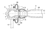
スタビライザリンク3は、アーム部2Bの端部と、車輪Wを支持する車体側部材としてのサスペンション装置20のショックアブソーバ21とを連結する。図2に示すように、スタビライザリンク3は、スタビライザバー2の開口端部に挿入固定される軸部4および軸部4の先端に形成されるボール部5を有するボールスタッド6と、ボール部5をユニバーサル方向に回転自在に支持するハウジング7と、一端がハウジング7の外面においてボールスタッド軸O1方向に移動しないように取り付けられ、他端が軸部4およびスタビライザバー2の内の少なくとも一方に取り付けられ、ハウジング7とボールスタッド6との隙間Sを密封する可撓性のダストカバー8とを備えている。
The stabilizer link 3 connects the end portion of the
ハウジング7は、一端側が開口した略円筒形状を呈した部材であり、その開口部から組み入れられたボールスタッド6のボール部5を球面軸受であるボールシート9を介してユニバーサル方向に回動自在に支持する。ハウジング7、ボールスタッド6は例えば金属製であり、ボールシート9は例えば合成樹脂材で形成されている。ハウジング7は繊維強化樹脂材等であってもよい。ハウジング7の外面には、ボールスタッド軸O1方向と略直交する方向に延びる連結バー10の一端が固定されており、連結バー10の他端側にも同様のハウジング7およびボールスタッド6が取り付けられている。連結バー10の他端側のボールスタッド6はショックアブソーバ21(図1)に取り付けられる。
The
「第1実施形態」
図2に示すように、ダストカバー8の一端は、ハウジング7の外周面7Aにリング部材11によりボールスタッド軸O1方向に移動しないように取り付けられている。ダストカバー8は、一端側および他端側が開口形成され、撓み代を確保するために径外方向に膨出した周壁部を有する部材であり、ゴム材等の可撓性材料により構成されている。リング部材11は、金属材料で構成されて例えば断面L字状を呈しており、ダストカバー8の端部にインサート成形等により埋設されている。ダストカバー8は、リング部材11が埋設された一端にハウジング7の外周面7Aが圧入されることにより、ハウジング7に対しボールスタッド軸O1方向に移動しないように取り付けられる。
"First embodiment"
As shown in FIG. 2, one end of the
リング部材11はダストカバー8と別体に設けてもよい。図3は、ダストカバー8の一端に溝を形成して、この溝に2条にコイル巻きした断面矩形状のリング部材11を嵌合させた形態を示している。この形態では、リング部材11が一旦拡径した状態となってダストカバー8の一端がハウジング7の外周面7Aに外嵌し、リング部材11が縮径しようとする弾性復元力により、ダストカバー8がハウジング7にボールスタッド軸O1方向に移動しないように取り付けられる。
The
ボールスタッド6の軸部4の外周面には、2条の鍔12A,12Bが形成され、ダストカバー8の他端は、鍔12A,12B間に挟持されるように軸部4の外周面に密着することで、軸部4に対しボールスタッド軸O1方向に移動しないように取り付けられる。軸部4の外周面に溝を凹設して、この溝にダストカバー8の他端を嵌合させるようにしてもよい。
Two
ボールスタッド6の軸部4は、スタビライザバー2の開口端部に挿入されて、プレス機等でスタビライザバー2の周壁部でかしめられる(周壁部を塑性変形させる)ことで、スタビライザバー2と一体に連結される。軸部4の外周面には、スタビライザバー2の内周面を喰い込ませるための凹凸形状部が形成されている。凹凸形状部としては、図2、図3に示すようにボールスタッド軸O1方向に複数の波状の凹凸を形成したり、平目やアヤ目からなるローレット目等である。
The
「作用」
一端がハウジング7にボールスタッド軸O1方向に移動しないように取り付けられ、ハウジング7とボールスタッド6との隙間Sを密封する可撓性のダストカバー8により、ボール部5周り、すなわちボールジョイント部への水や塵埃等の浸入が阻止される。ハウジング7へのダストカバー8の取り付け構造として、金属製のリング部材11を介してダストカバー8の一端をハウジング7の外周面7Aに外嵌させる構造とすることで、ハウジング7へのダストカバー8の組み付け作業を迅速に行える。
"Action"
A
ダストカバー8の他端を軸部5においてボールスタッド軸O1方向に移動しないように取り付ける構造とすることで、ダストカバー8をハウジング7と軸部5とに既に組み付けた状態として、軸部5をスタビライザバー2の開口端部に固定することができる。ダストカバー8の他端を2条の鍔12A,12Bで挟持する構造により、軸部5へのダストカバー8の組み付け作業を迅速に行える。
By adopting a structure in which the other end of the
スタビライザバー2の開口端部への水や塵埃等の浸入は、この開口端部周りがボールスタッド6の外周面にかしめられることで阻止される。特にボールスタッド6の外周面にボールスタッド軸O1方向に複数の凹凸を形成したり、ローレット目を形成することで、水や塵埃の浸入をこれら凹凸部のラビリンス構造で確実に阻止できる。
The ingress of water, dust, etc. into the opening end of the
「第2実施形態」
図4において、第2実施形態に係るダストカバー18は、その他端がスタビライザバー2においてボールスタッド軸O1方向に移動しないように取り付けられている。ダストカバー18の他端には、例えば一端側と同様に金属製のリング部材13が埋設されている。ダストカバー18は、リング部材13が埋設された他端にスタビライザバー2の外周面が圧入されることにより、スタビライザバー2に対しボールスタッド軸O1方向に移動しないように取り付けられる。リング部材11はダストカバー18と別体に設けてもよい。また、スタビライザバー2の外周面に溝等を形成してダストカバー18の他端をその溝に嵌合させるようにしてもよい。第1実施形態と同様、ボールスタッド6の軸部4は、スタビライザバー2の開口端部に挿入されて、プレス機等でスタビライザバー2の周壁部でかしめられることで、スタビライザバー2と一体に連結される。
"Second embodiment"
In FIG. 4, the
かしめ加工時においては、ダストカバー18を撓ませてプレス機と干渉しないようにその他端をハウジング7寄りに一旦退避させた状態で、軸部4とスタビライザバー2とをかしめ固定する。その後、ダストカバー18の他端をスタビライザバー2の外周面にリング部材11により密着させる。
At the time of caulking, the
本実施形態の場合、ダストカバー18がハウジング7とスタビライザバー2とにわたって掛け渡されることとなるので、ダストカバー18のボーススタッド軸O1方向の長さが長くなる。このような場合、ダストカバー18を蛇腹形状にすれば、ボールジョイントの動きに対するダストカバー18の追従性を高めることができる。
In the case of the present embodiment, since the
本実施形態によれば、ダストカバー18により、ボールジョイント部への水や塵埃等の浸入を阻止できるとともに、スタビライザバー2と軸部4との隙間への水や塵埃等の浸入も阻止できる。
According to the present embodiment, the
「第3実施形態」
図5において、第3実施形態に係るダストカバー28は、その一端と他端との間が軸部4においてボールスタッド軸O1方向に移動しないように取り付けられ、かつ他端がスタビライザバー2の外周面に密着している。ダストカバー28の一端と他端との間は、例えば鍔12A,12Bに挟持されることで軸部4においてボールスタッド軸O1方向に移動しないように取り付けられる。ダストカバー28の内で軸部4への取り付け部から他端までの範囲は覆い部14とされる。
"Third embodiment"
In FIG. 5, the
第1実施形態と同様、ボールスタッド6の軸部4は、スタビライザバー2の開口端部に挿入されて、プレス機等でスタビライザバー2の周壁部でかしめられることで、スタビライザバー2と一体に連結される。かしめ加工時においては、覆い部14を撓ませてプレス機と干渉しないように仮想線で示すように裏返してハウジング7側に一旦退避させた状態で、軸部4とスタビライザバー2とをかしめ固定する。その後、矢印で示すように覆い部14を捲り上げて、覆い部14の他端をスタビライザバー2の外周面に密着させる。なお、かしめ加工時に、プレス機でスタビライザバー2の外周面に凸形状または凹形状からなるずれ止め部16を同時に形成しておけば、覆い部14の他端のずれをずれ止め部16で抑制できる。
Similar to the first embodiment, the
本実施形態によれば、ダストカバー28により、ボールジョイント部への水や塵埃等の浸入を阻止できるとともに、覆い部14により、スタビライザバー2と軸部4との隙間への水や塵埃等の浸入も阻止できる。覆い部14の他端側はボールジョイント部の動きの影響をさほど受けないので、スタビライザバー2の外周面に対するずれもさほど生じることがなく、初期の密着性が維持される。
According to the present embodiment, the
図6は、第3実施形態の変形例を示している。図5では、ダストカバー28の一端と他端との間を軸部4の鍔12A,12Bで挟持しているが、図6はダストカバー28の一端と他端との間を軸部4の外周面に単に密着させている。図5の場合と同様、かしめ加工時においては、覆い部14はプレス機と干渉しないように仮想線で示すように裏返された状態でハウジング7側に一旦退避した状態にあり、軸部4とスタビライザバー2とのかしめ加工が完了した後に矢印で示すように覆い部14を捲り上げて、覆い部14の他端をスタビライザバー2の外周面に密着させる。また、スタビライザバー2の外周面にずれ止め部16を形成しておけば、覆い部14の他端のずれをずれ止め部16で抑制できる。
FIG. 6 shows a modified example of the third embodiment. In FIG. 5, one end and the other end of the
本変形例によっても、ダストカバー28により、ボールジョイント部への水や塵埃等の浸入を阻止できるとともに、覆い部14により、スタビライザバー2と軸部4との隙間への水や塵埃等の浸入も阻止できる。覆い部14の他端側はボールジョイント部の動きの影響をさほど受けないので、スタビライザバー2の外周面に対するずれもさほど生じることがなく、初期の密着性が維持される。本変形例では、鍔12A,12Bによる移動規制はないものの、軸部4と密着する部分のダストカバー28の径寸法を適宜に設定することで、密着度を高めることができる。また、覆い部14の他端側で密封機能が維持されてさえいれば、軸部4でのずれもさほど問題とはならない。
Also in this modified example, the
以上、ダストカバー8の取り付けに関する好適な実施形態を説明した。以上の実施形態では、リング部材11を用いてダストカバー8の一端をハウジング7の外周面7Aに取り付けているが、図7に示すように、ハウジング7の外周面7Aに溝を形成してこの溝にダストカバー8の一端を嵌合させるようにしてもよい。
The preferred embodiment for attaching the
また、図8に示すように、ボールシート9の縁部9Aをハウジング7の外部に配置させ、縁部9Aとハウジング7の開口縁部とでダストカバー8の一端を挟持する構造にしてもよい。
Further, as shown in FIG. 8, the
ボールスタッド6の軸部4とスタビライザバー2との間の水密性を確保するにあたっては、かしめによる構造以外でも可能である。図9は、軸部24の末端に、スタビライザバー2の開口端部の内径よりも大径でボールスタッド軸O1を中心に円錐形をなすテーパ面24Aを形成し、テーパ面24Aをスタビライザバー2の開口端部に突き当てて、その突き当て部を溶着した構造を示している。テーパ面24Aはボールスタッド軸O1を中心に形成されているので、突き当てるだけで軸部24とスタビライザバー2との芯出しがなされる。溶着としては例えば溶接であり、抵抗溶接であってもよいしTIG溶接等であってもよい。、
In ensuring the watertightness between the
また、軸部4をスタビライザバー2の開口端部に圧入により挿入することで水密性を確保するようにしてもよい。スタビライザバー2の径は車の仕様により様々なサイズが存在するため、図10に示すように、軸部34とスタビライザバー2との間にカラー15を介在させる構造とすれば、複数サイズのカラー15を用意することで、軸部34の仕様変更なしに圧入寸法を容易に合わせることができる。カラー15は、例えば軸部34に圧入により外嵌した状態で、スタビライザバー2の開口端部に圧入により挿入される。
Further, the
また、その他に、軸部4の外周面とスタビライザバー2の内周面との間を接着剤で結合することで水密性を確保するようにしてもよい。
In addition, watertightness may be ensured by bonding the outer peripheral surface of the
1 スタビライザ装置
2 スタビライザバー
3 スタビライザリンク
4,24,34 軸部
5 ボール部
7 ハウジング
8,18,28 ダストカバー
11,13 リング部材
14 覆い部材
15 カラー
1
Claims (6)
前記スタビライザリンクは、
前記スタビライザバーの開口端部に挿入固定される軸部および該軸部の先端に形成されるボール部を有するボールスタッドと、
前記ボール部を回転自在に支持するハウジングと、
一端が前記ハウジングにおいてボールスタッド軸方向に移動しないように取り付けられ、他端が前記スタビライザバーに取り付けられ、前記ハウジングと前記ボールスタッドとの隙間を密封する可撓性のダストカバーと、
を備え、
前記ダストカバーは、その一端と他端との間に前記軸部においてボールスタッド軸方向に移動しないように取り付けられる取り付け部を有し、かつ他端が前記スタビライザバーの外周面に密着しており、
前記取り付け部から前記他端までの範囲は、前記スタビライザバーを覆う覆い部を構成し、
前記覆い部は、径方向外側に膨らんだ形状を成し、前記スタビライザバーに密着していない
ことを特徴とするスタビライザ装置。 A stabilizer device having a stabilizer bar made of a pipe material and a stabilizer link for connecting the stabilizer bar and the suspension device.
The stabilizer link is
A ball stud having a shaft portion to be inserted and fixed to the open end portion of the stabilizer bar and a ball portion formed at the tip of the shaft portion.
A housing that rotatably supports the ball portion and
A flexible dust cover having one end attached to the housing so as not to move in the axial direction of the ball stud and the other end attached to the stabilizer bar to seal the gap between the housing and the ball stud.
Equipped with a,
The dust cover has a mounting portion that is mounted between one end and the other end of the dust cover so as not to move in the ball stud axial direction at the shaft portion, and the other end is in close contact with the outer peripheral surface of the stabilizer bar. ,
The range from the mounting portion to the other end constitutes a covering portion that covers the stabilizer bar.
A stabilizer device characterized in that the covering portion has a shape bulging outward in the radial direction and is not in close contact with the stabilizer bar .
ことを特徴とする請求項1に記載のスタビライザ装置。 The first aspect of the present invention is characterized in that two flanges are formed on the outer peripheral surface of the shaft portion, and the mounting portion is sandwiched between the two flanges and is in close contact with the outer peripheral surface of the shaft portion. The stabilizer device described.
前記軸部は、前記テーパ面が前記スタビライザバーの開口端部に突き当てられて溶着により前記スタビライザバーに固定されることを特徴とする請求項1ないし請求項3のいずれか一項に記載のスタビライザ装置。 At the end of the shaft portion, a tapered surface having a diameter larger than the inner diameter of the open end portion of the stabilizer bar and forming a conical shape around the ball stud shaft is formed.
The shaft portion according to any one of claims 1 to 3 , wherein the tapered surface is abutted against the open end portion of the stabilizer bar and fixed to the stabilizer bar by welding. Stabilizer device.
前記スタビライザリンクは、
前記スタビライザバーの開口端部に挿入固定される軸部および該軸部の先端に形成されるボール部を有するボールスタッドと、
前記ボール部を回転自在に支持するハウジングと、
一端が前記ハウジングにおいてボールスタッド軸方向に移動しないように取り付けられ、他端が前記スタビライザバーに取り付けられ、前記ハウジングと前記ボールスタッドとの隙間を密封する可撓性のダストカバーと、
を備え、
前記ダストカバーは、その一端と他端との間に前記軸部においてボールスタッド軸方向に移動しないように取り付けられる取り付け部を有し、かつ他端が前記スタビライザバーの外周面に密着しており、
前記取り付け部から前記他端までの範囲は、前記スタビライザバーを覆う覆い部を構成し、
前記覆い部は、径方向外側に膨らんだ形状を成し、前記スタビライザバーに密着しておらず、
前記ダストカバーの一端を前記ハウジングに取り付けるとともに、前記取り付け部を前記軸部に取り付け、前記ダストカバーの覆い部を撓ませてその他端を前記ハウジング寄りに一旦退避させた状態で前記軸部と前記スタビライザバーとを固定し、その後、前記ダストカバーの他端を前記スタビライザバーの外周面に密着させるとともに、前記覆い部で前記軸部と前記スタビライザバーの接続部分を覆うことを特徴とするスタビライザ装置の組み立て方法。 In a stabilizer device having a stabilizer bar made of a pipe material and a stabilizer link connecting the stabilizer bar and the suspension device.
The stabilizer link is
A ball stud having a shaft portion to be inserted and fixed to the open end portion of the stabilizer bar and a ball portion formed at the tip of the shaft portion.
A housing that rotatably supports the ball portion and
A flexible dust cover having one end attached to the housing so as not to move in the axial direction of the ball stud and the other end attached to the stabilizer bar to seal the gap between the housing and the ball stud.
With
The dust cover has a mounting portion that is mounted between one end and the other end of the dust cover so as not to move in the ball stud axial direction at the shaft portion, and the other end is in close contact with the outer peripheral surface of the stabilizer bar. ,
The range from the mounting portion to the other end constitutes a covering portion that covers the stabilizer bar.
The covering portion has a shape that bulges outward in the radial direction and does not adhere to the stabilizer bar.
One end of the dust cover is attached to the housing, the attachment portion is attached to the shaft portion, the cover portion of the dust cover is bent, and the other end is temporarily retracted toward the housing. The stabilizer device is characterized in that the stabilizer bar is fixed, and then the other end of the dust cover is brought into close contact with the outer peripheral surface of the stabilizer bar, and the connecting portion between the shaft portion and the stabilizer bar is covered with the covering portion. How to assemble.
Priority Applications (9)
| Application Number | Priority Date | Filing Date | Title |
|---|---|---|---|
| JP2016172571A JP6762176B2 (en) | 2016-09-05 | 2016-09-05 | Stabilizer device and how to assemble it |
| EP17846053.1A EP3508361A4 (en) | 2016-09-05 | 2017-08-07 | Stabilizer and assembling method therefor |
| CN201780053789.9A CN109641503B (en) | 2016-09-05 | 2017-08-07 | Stabilizing device and method of assembling the same |
| PCT/JP2017/028546 WO2018043044A1 (en) | 2016-09-05 | 2017-08-07 | Stabilizer and assembling method therefor |
| US16/330,354 US10850589B2 (en) | 2016-09-05 | 2017-08-07 | Stabilizer and assembling method therefor |
| MX2019002538A MX2019002538A (en) | 2016-09-05 | 2017-08-07 | Stabilizer and assembling method therefor. |
| BR112019003518-4A BR112019003518B1 (en) | 2016-09-05 | 2017-08-07 | STABILIZER AND ASSEMBLY METHOD THEREOF |
| CA3035735A CA3035735C (en) | 2016-09-05 | 2017-08-07 | Stabilizer and assembling method therefor |
| KR1020197009437A KR102210839B1 (en) | 2016-09-05 | 2017-08-07 | Stabilizer device and assembly method thereof |
Applications Claiming Priority (1)
| Application Number | Priority Date | Filing Date | Title |
|---|---|---|---|
| JP2016172571A JP6762176B2 (en) | 2016-09-05 | 2016-09-05 | Stabilizer device and how to assemble it |
Publications (2)
| Publication Number | Publication Date |
|---|---|
| JP2018039279A JP2018039279A (en) | 2018-03-15 |
| JP6762176B2 true JP6762176B2 (en) | 2020-09-30 |
Family
ID=61300459
Family Applications (1)
| Application Number | Title | Priority Date | Filing Date |
|---|---|---|---|
| JP2016172571A Active JP6762176B2 (en) | 2016-09-05 | 2016-09-05 | Stabilizer device and how to assemble it |
Country Status (9)
| Country | Link |
|---|---|
| US (1) | US10850589B2 (en) |
| EP (1) | EP3508361A4 (en) |
| JP (1) | JP6762176B2 (en) |
| KR (1) | KR102210839B1 (en) |
| CN (1) | CN109641503B (en) |
| BR (1) | BR112019003518B1 (en) |
| CA (1) | CA3035735C (en) |
| MX (1) | MX2019002538A (en) |
| WO (1) | WO2018043044A1 (en) |
Families Citing this family (5)
| Publication number | Priority date | Publication date | Assignee | Title |
|---|---|---|---|---|
| JP6762176B2 (en) | 2016-09-05 | 2020-09-30 | 日本発條株式会社 | Stabilizer device and how to assemble it |
| USD894797S1 (en) * | 2018-11-20 | 2020-09-01 | Ki Kwang Lee | Link packing installed between track bush and bottom of link counter hole for road-rail vehicle |
| KR102649394B1 (en) * | 2019-10-14 | 2024-03-20 | 현대모비스 주식회사 | Stabilizer bar link for vhicle |
| JP7674731B2 (en) * | 2021-05-14 | 2025-05-12 | 株式会社ソミックマネージメントホールディングス | Manufacturing method of arm member |
| DE102024110522B4 (en) * | 2024-04-15 | 2026-01-15 | Muhr Und Bender Kg | Stabilizer for the chassis of a motor vehicle and method for manufacturing a stabilizer |
Family Cites Families (20)
| Publication number | Priority date | Publication date | Assignee | Title |
|---|---|---|---|---|
| JPH01182109A (en) | 1988-01-18 | 1989-07-20 | Nhk Spring Co Ltd | Vehicle stabilizer |
| JPH0334910U (en) * | 1989-08-15 | 1991-04-05 | ||
| JPH08127220A (en) * | 1994-10-31 | 1996-05-21 | Chuo Spring Co Ltd | Automotive stabilizer bar |
| US5954353A (en) | 1998-02-06 | 1999-09-21 | American Axle & Manufacturing, Inc. | Plug in direct acting stabilizer bar link |
| US6076840A (en) * | 1998-05-19 | 2000-06-20 | American Axle & Manufacturing, Inc. | Self-locking plug-in stabilizer bar links |
| EP1065077A1 (en) * | 1999-07-01 | 2001-01-03 | American Axle & Manufacturing Inc. | Plug in direct acting stabilizer bar link |
| US6648350B1 (en) * | 2000-05-08 | 2003-11-18 | Meritor Light Vehicle Systems, Inc. | Suspension system for a vehicle having a vehicle stabilizer bar with integral end links |
| DE10156548A1 (en) * | 2001-11-20 | 2003-05-28 | Zf Lemfoerder Metallwaren Ag | Joint between two parts able to move relative to each other has curved bearing surface passing into journal neck on one side |
| US7004665B2 (en) * | 2002-11-08 | 2006-02-28 | Automotive Components Holdings, Llc | Snap together automotive coupler |
| CN100368693C (en) * | 2003-04-07 | 2008-02-13 | 株式会社索密克石川 | ball joint |
| CN101161490A (en) * | 2006-10-10 | 2008-04-16 | 北汽福田汽车股份有限公司 | An automobile independent rear suspension and automobile including the same |
| JP2011247338A (en) * | 2010-05-26 | 2011-12-08 | Nhk Spring Co Ltd | Stabilizer link and method for producing the same |
| CN103277404B (en) * | 2013-06-26 | 2015-10-14 | 玉环津力汽车配件有限公司 | Automobile ball component |
| KR101500239B1 (en) * | 2013-12-23 | 2015-03-06 | 현대자동차주식회사 | Stabilizer link |
| JP6204521B2 (en) * | 2016-03-17 | 2017-09-27 | 日本発條株式会社 | Ball joint and stabilizer link using the same |
| DE102016206863A1 (en) * | 2016-04-22 | 2017-10-26 | Zf Friedrichshafen Ag | Axial ball joint and adjustable length two-point link with such an axial ball joint |
| JP6335986B2 (en) * | 2016-08-25 | 2018-05-30 | 日本発條株式会社 | Stabillink |
| JP6762176B2 (en) | 2016-09-05 | 2020-09-30 | 日本発條株式会社 | Stabilizer device and how to assemble it |
| JP6648001B2 (en) * | 2016-11-02 | 2020-02-14 | 日本発條株式会社 | Stabilizer link |
| JP6768584B2 (en) * | 2017-03-31 | 2020-10-14 | 日本発條株式会社 | Ball joint manufacturing method and stabilizer link manufacturing method |
-
2016
- 2016-09-05 JP JP2016172571A patent/JP6762176B2/en active Active
-
2017
- 2017-08-07 CA CA3035735A patent/CA3035735C/en active Active
- 2017-08-07 KR KR1020197009437A patent/KR102210839B1/en active Active
- 2017-08-07 MX MX2019002538A patent/MX2019002538A/en unknown
- 2017-08-07 WO PCT/JP2017/028546 patent/WO2018043044A1/en not_active Ceased
- 2017-08-07 CN CN201780053789.9A patent/CN109641503B/en active Active
- 2017-08-07 BR BR112019003518-4A patent/BR112019003518B1/en active IP Right Grant
- 2017-08-07 EP EP17846053.1A patent/EP3508361A4/en not_active Withdrawn
- 2017-08-07 US US16/330,354 patent/US10850589B2/en active Active
Also Published As
| Publication number | Publication date |
|---|---|
| EP3508361A1 (en) | 2019-07-10 |
| US10850589B2 (en) | 2020-12-01 |
| US20190202255A1 (en) | 2019-07-04 |
| CA3035735A1 (en) | 2018-03-08 |
| JP2018039279A (en) | 2018-03-15 |
| KR102210839B1 (en) | 2021-02-02 |
| WO2018043044A1 (en) | 2018-03-08 |
| CN109641503A (en) | 2019-04-16 |
| EP3508361A4 (en) | 2020-04-22 |
| CA3035735C (en) | 2021-03-09 |
| BR112019003518B1 (en) | 2024-02-20 |
| MX2019002538A (en) | 2019-07-15 |
| KR20190041529A (en) | 2019-04-22 |
| BR112019003518A2 (en) | 2019-05-21 |
| CN109641503B (en) | 2022-04-08 |
Similar Documents
| Publication | Publication Date | Title |
|---|---|---|
| JP6762176B2 (en) | Stabilizer device and how to assemble it | |
| EP2868501B1 (en) | Ball joint | |
| KR101538422B1 (en) | Curled bushing with torsional slip | |
| JP6315147B2 (en) | Ball joint | |
| CN101909911A (en) | vehicle stabilizer | |
| WO2017159822A1 (en) | Ball joint, and stabilizer link using same | |
| TW201816294A (en) | High angularity ball joint assembly | |
| JP2000107952A (en) | Manufacture of stabilizer connecting rod | |
| JPWO2018105528A1 (en) | Resin boots | |
| JP5048410B2 (en) | Stabilizer support structure | |
| JP2011020673A (en) | Supporting structure of stabilizer | |
| JP6943420B2 (en) | Clip members and ball joints | |
| CN114025973B (en) | Stabilizer | |
| JP7790694B2 (en) | Shaft Coupling Device | |
| JP7703770B2 (en) | Ball joint seal structure | |
| JP4092274B2 (en) | Hydraulic shock absorber mounting | |
| KR20250156406A (en) | Stabilizer bar link of vehicle and manufacturing method thereof | |
| KR20130022875A (en) | Stabilizer link for a car | |
| KR101840792B1 (en) | Joint structure of stabilizer link | |
| JP4660331B2 (en) | Sliding bush assembly | |
| JP2004270835A (en) | Ball joint device | |
| KR102224007B1 (en) | Pillow ball joint assembly | |
| CN104411520B (en) | ball joint | |
| JP6531543B2 (en) | Cross bearing | |
| JP2550142Y2 (en) | Sliding rubber bush |
Legal Events
| Date | Code | Title | Description |
|---|---|---|---|
| A621 | Written request for application examination |
Free format text: JAPANESE INTERMEDIATE CODE: A621 Effective date: 20190417 |
|
| A131 | Notification of reasons for refusal |
Free format text: JAPANESE INTERMEDIATE CODE: A131 Effective date: 20200218 |
|
| A601 | Written request for extension of time |
Free format text: JAPANESE INTERMEDIATE CODE: A601 Effective date: 20200417 |
|
| A521 | Request for written amendment filed |
Free format text: JAPANESE INTERMEDIATE CODE: A523 Effective date: 20200618 |
|
| TRDD | Decision of grant or rejection written | ||
| A01 | Written decision to grant a patent or to grant a registration (utility model) |
Free format text: JAPANESE INTERMEDIATE CODE: A01 Effective date: 20200901 |
|
| A61 | First payment of annual fees (during grant procedure) |
Free format text: JAPANESE INTERMEDIATE CODE: A61 Effective date: 20200908 |
|
| R150 | Certificate of patent or registration of utility model |
Ref document number: 6762176 Country of ref document: JP Free format text: JAPANESE INTERMEDIATE CODE: R150 |
|
| R250 | Receipt of annual fees |
Free format text: JAPANESE INTERMEDIATE CODE: R250 |
|
| R250 | Receipt of annual fees |
Free format text: JAPANESE INTERMEDIATE CODE: R250 |
|
| R250 | Receipt of annual fees |
Free format text: JAPANESE INTERMEDIATE CODE: R250 |