JP6761489B2 - Surgical equipment and methods - Google Patents
Surgical equipment and methods Download PDFInfo
- Publication number
- JP6761489B2 JP6761489B2 JP2018566209A JP2018566209A JP6761489B2 JP 6761489 B2 JP6761489 B2 JP 6761489B2 JP 2018566209 A JP2018566209 A JP 2018566209A JP 2018566209 A JP2018566209 A JP 2018566209A JP 6761489 B2 JP6761489 B2 JP 6761489B2
- Authority
- JP
- Japan
- Prior art keywords
- spinal implant
- surgical
- respect
- orientation
- image guide
- Prior art date
- Legal status (The legal status is an assumption and is not a legal conclusion. Google has not performed a legal analysis and makes no representation as to the accuracy of the status listed.)
- Active
Links
- 238000000034 method Methods 0.000 title description 20
- 239000007943 implant Substances 0.000 claims description 180
- 210000001519 tissue Anatomy 0.000 description 22
- 239000003550 marker Substances 0.000 description 16
- 239000000463 material Substances 0.000 description 16
- 238000013519 translation Methods 0.000 description 16
- 230000014616 translation Effects 0.000 description 16
- 238000001356 surgical procedure Methods 0.000 description 15
- 210000000988 bone and bone Anatomy 0.000 description 14
- 210000003484 anatomy Anatomy 0.000 description 12
- 208000037265 diseases, disorders, signs and symptoms Diseases 0.000 description 12
- 238000003780 insertion Methods 0.000 description 12
- 230000037431 insertion Effects 0.000 description 12
- 201000010099 disease Diseases 0.000 description 10
- 238000003384 imaging method Methods 0.000 description 10
- 239000002131 composite material Substances 0.000 description 8
- 238000013459 approach Methods 0.000 description 7
- 229920000642 polymer Polymers 0.000 description 7
- -1 Nitinol Chemical class 0.000 description 6
- 238000005259 measurement Methods 0.000 description 6
- 208000029497 Elastoma Diseases 0.000 description 5
- 239000004696 Poly ether ether ketone Substances 0.000 description 5
- 208000020307 Spinal disease Diseases 0.000 description 5
- 239000000919 ceramic Substances 0.000 description 5
- 230000008859 change Effects 0.000 description 5
- 230000013011 mating Effects 0.000 description 5
- 229920002530 polyetherether ketone Polymers 0.000 description 5
- 125000006850 spacer group Chemical group 0.000 description 5
- 208000024891 symptom Diseases 0.000 description 5
- 206010017076 Fracture Diseases 0.000 description 4
- 206010023509 Kyphosis Diseases 0.000 description 4
- 230000002745 absorbent Effects 0.000 description 4
- 239000002250 absorbent Substances 0.000 description 4
- 239000001506 calcium phosphate Substances 0.000 description 4
- 229920001971 elastomer Polymers 0.000 description 4
- 238000002594 fluoroscopy Methods 0.000 description 4
- 208000014674 injury Diseases 0.000 description 4
- 230000001788 irregular Effects 0.000 description 4
- 210000004197 pelvis Anatomy 0.000 description 4
- 230000005855 radiation Effects 0.000 description 4
- QORWJWZARLRLPR-UHFFFAOYSA-H tricalcium bis(phosphate) Chemical compound [Ca+2].[Ca+2].[Ca+2].[O-]P([O-])([O-])=O.[O-]P([O-])([O-])=O QORWJWZARLRLPR-UHFFFAOYSA-H 0.000 description 4
- 230000000007 visual effect Effects 0.000 description 4
- OYPRJOBELJOOCE-UHFFFAOYSA-N Calcium Chemical compound [Ca] OYPRJOBELJOOCE-UHFFFAOYSA-N 0.000 description 3
- 208000003618 Intervertebral Disc Displacement Diseases 0.000 description 3
- 208000027418 Wounds and injury Diseases 0.000 description 3
- 230000001154 acute effect Effects 0.000 description 3
- 229910052791 calcium Inorganic materials 0.000 description 3
- 239000011575 calcium Substances 0.000 description 3
- 230000006378 damage Effects 0.000 description 3
- 229910052751 metal Inorganic materials 0.000 description 3
- 239000002184 metal Substances 0.000 description 3
- 230000036407 pain Effects 0.000 description 3
- 230000008439 repair process Effects 0.000 description 3
- 239000007787 solid Substances 0.000 description 3
- 239000000126 substance Substances 0.000 description 3
- 239000004606 Fillers/Extenders Substances 0.000 description 2
- 206010061246 Intervertebral disc degeneration Diseases 0.000 description 2
- 206010050296 Intervertebral disc protrusion Diseases 0.000 description 2
- XEEYBQQBJWHFJM-UHFFFAOYSA-N Iron Chemical compound [Fe] XEEYBQQBJWHFJM-UHFFFAOYSA-N 0.000 description 2
- 208000023178 Musculoskeletal disease Diseases 0.000 description 2
- 206010028980 Neoplasm Diseases 0.000 description 2
- 208000001132 Osteoporosis Diseases 0.000 description 2
- 208000031481 Pathologic Constriction Diseases 0.000 description 2
- 229910001069 Ti alloy Inorganic materials 0.000 description 2
- RTAQQCXQSZGOHL-UHFFFAOYSA-N Titanium Chemical compound [Ti] RTAQQCXQSZGOHL-UHFFFAOYSA-N 0.000 description 2
- 239000000853 adhesive Substances 0.000 description 2
- 230000001070 adhesive effect Effects 0.000 description 2
- 229910000389 calcium phosphate Inorganic materials 0.000 description 2
- 235000011010 calcium phosphates Nutrition 0.000 description 2
- OSGAYBCDTDRGGQ-UHFFFAOYSA-L calcium sulfate Chemical compound [Ca+2].[O-]S([O-])(=O)=O OSGAYBCDTDRGGQ-UHFFFAOYSA-L 0.000 description 2
- 238000004891 communication Methods 0.000 description 2
- 230000001054 cortical effect Effects 0.000 description 2
- 208000018180 degenerative disc disease Diseases 0.000 description 2
- 238000002059 diagnostic imaging Methods 0.000 description 2
- 208000035475 disorder Diseases 0.000 description 2
- 239000003814 drug Substances 0.000 description 2
- 229940079593 drug Drugs 0.000 description 2
- 230000004927 fusion Effects 0.000 description 2
- 230000005484 gravity Effects 0.000 description 2
- 229910052588 hydroxylapatite Inorganic materials 0.000 description 2
- 208000021600 intervertebral disc degenerative disease Diseases 0.000 description 2
- 210000003041 ligament Anatomy 0.000 description 2
- 150000002739 metals Chemical class 0.000 description 2
- 238000002324 minimally invasive surgery Methods 0.000 description 2
- 230000003287 optical effect Effects 0.000 description 2
- XYJRXVWERLGGKC-UHFFFAOYSA-D pentacalcium;hydroxide;triphosphate Chemical compound [OH-].[Ca+2].[Ca+2].[Ca+2].[Ca+2].[Ca+2].[O-]P([O-])([O-])=O.[O-]P([O-])([O-])=O.[O-]P([O-])([O-])=O XYJRXVWERLGGKC-UHFFFAOYSA-D 0.000 description 2
- 229920001643 poly(ether ketone) Polymers 0.000 description 2
- 229920001652 poly(etherketoneketone) Polymers 0.000 description 2
- 229920006260 polyaryletherketone Polymers 0.000 description 2
- 229920000139 polyethylene terephthalate Polymers 0.000 description 2
- 239000005020 polyethylene terephthalate Substances 0.000 description 2
- 229920001296 polysiloxane Polymers 0.000 description 2
- 229920002635 polyurethane Polymers 0.000 description 2
- 239000004814 polyurethane Substances 0.000 description 2
- 206010039722 scoliosis Diseases 0.000 description 2
- 230000036262 stenosis Effects 0.000 description 2
- 208000037804 stenosis Diseases 0.000 description 2
- 229920001169 thermoplastic Polymers 0.000 description 2
- 239000004416 thermosoftening plastic Substances 0.000 description 2
- 229910052719 titanium Inorganic materials 0.000 description 2
- 239000010936 titanium Substances 0.000 description 2
- 229910000391 tricalcium phosphate Inorganic materials 0.000 description 2
- 235000019731 tricalcium phosphate Nutrition 0.000 description 2
- 229940078499 tricalcium phosphate Drugs 0.000 description 2
- LQIAZOCLNBBZQK-UHFFFAOYSA-N 1-(1,2-Diphosphanylethyl)pyrrolidin-2-one Chemical compound PCC(P)N1CCCC1=O LQIAZOCLNBBZQK-UHFFFAOYSA-N 0.000 description 1
- OKTJSMMVPCPJKN-UHFFFAOYSA-N Carbon Chemical compound [C] OKTJSMMVPCPJKN-UHFFFAOYSA-N 0.000 description 1
- BVKZGUZCCUSVTD-UHFFFAOYSA-L Carbonate Chemical compound [O-]C([O-])=O BVKZGUZCCUSVTD-UHFFFAOYSA-L 0.000 description 1
- 206010011985 Decubitus ulcer Diseases 0.000 description 1
- 239000004593 Epoxy Substances 0.000 description 1
- AEMRFAOFKBGASW-UHFFFAOYSA-N Glycolic acid Polymers OCC(O)=O AEMRFAOFKBGASW-UHFFFAOYSA-N 0.000 description 1
- 229910000787 Gum metal Inorganic materials 0.000 description 1
- 206010061218 Inflammation Diseases 0.000 description 1
- 241000124008 Mammalia Species 0.000 description 1
- 241001465754 Metazoa Species 0.000 description 1
- 208000028389 Nerve injury Diseases 0.000 description 1
- 208000008558 Osteophyte Diseases 0.000 description 1
- 235000010627 Phaseolus vulgaris Nutrition 0.000 description 1
- 244000046052 Phaseolus vulgaris Species 0.000 description 1
- 239000004952 Polyamide Substances 0.000 description 1
- 239000004697 Polyetherimide Substances 0.000 description 1
- 239000004698 Polyethylene Substances 0.000 description 1
- 229920000954 Polyglycolide Polymers 0.000 description 1
- 239000004642 Polyimide Substances 0.000 description 1
- 229920000265 Polyparaphenylene Polymers 0.000 description 1
- 208000007103 Spondylolisthesis Diseases 0.000 description 1
- 230000005856 abnormality Effects 0.000 description 1
- 208000038016 acute inflammation Diseases 0.000 description 1
- 230000006022 acute inflammation Effects 0.000 description 1
- 230000032683 aging Effects 0.000 description 1
- 230000000735 allogeneic effect Effects 0.000 description 1
- 229910052782 aluminium Inorganic materials 0.000 description 1
- XAGFODPZIPBFFR-UHFFFAOYSA-N aluminium Chemical compound [Al] XAGFODPZIPBFFR-UHFFFAOYSA-N 0.000 description 1
- 238000003491 array Methods 0.000 description 1
- 238000010420 art technique Methods 0.000 description 1
- 230000000712 assembly Effects 0.000 description 1
- 238000000429 assembly Methods 0.000 description 1
- 210000001124 body fluid Anatomy 0.000 description 1
- 239000010839 body fluid Substances 0.000 description 1
- 229910052799 carbon Inorganic materials 0.000 description 1
- 210000000845 cartilage Anatomy 0.000 description 1
- 239000003638 chemical reducing agent Substances 0.000 description 1
- 239000000788 chromium alloy Substances 0.000 description 1
- 208000037976 chronic inflammation Diseases 0.000 description 1
- 230000006020 chronic inflammation Effects 0.000 description 1
- 230000008878 coupling Effects 0.000 description 1
- 238000010168 coupling process Methods 0.000 description 1
- 238000005859 coupling reaction Methods 0.000 description 1
- 230000006837 decompression Effects 0.000 description 1
- 230000007850 degeneration Effects 0.000 description 1
- 230000003412 degenerative effect Effects 0.000 description 1
- 238000003745 diagnosis Methods 0.000 description 1
- 230000004069 differentiation Effects 0.000 description 1
- 230000000694 effects Effects 0.000 description 1
- 238000005516 engineering process Methods 0.000 description 1
- 239000004744 fabric Substances 0.000 description 1
- 239000003102 growth factor Substances 0.000 description 1
- 230000035876 healing Effects 0.000 description 1
- 239000000017 hydrogel Substances 0.000 description 1
- 230000001939 inductive effect Effects 0.000 description 1
- 230000004054 inflammatory process Effects 0.000 description 1
- 229910052742 iron Inorganic materials 0.000 description 1
- 238000002955 isolation Methods 0.000 description 1
- 238000002684 laminectomy Methods 0.000 description 1
- 230000003902 lesion Effects 0.000 description 1
- 229910001092 metal group alloy Inorganic materials 0.000 description 1
- 238000012986 modification Methods 0.000 description 1
- 230000004048 modification Effects 0.000 description 1
- 230000008764 nerve damage Effects 0.000 description 1
- 229910001000 nickel titanium Inorganic materials 0.000 description 1
- HLXZNVUGXRDIFK-UHFFFAOYSA-N nickel titanium Chemical compound [Ti].[Ti].[Ti].[Ti].[Ti].[Ti].[Ti].[Ti].[Ti].[Ti].[Ti].[Ni].[Ni].[Ni].[Ni].[Ni].[Ni].[Ni].[Ni].[Ni].[Ni].[Ni].[Ni].[Ni].[Ni] HLXZNVUGXRDIFK-UHFFFAOYSA-N 0.000 description 1
- 238000002355 open surgical procedure Methods 0.000 description 1
- 230000035699 permeability Effects 0.000 description 1
- 230000000144 pharmacologic effect Effects 0.000 description 1
- 229920002647 polyamide Polymers 0.000 description 1
- 229920001601 polyetherimide Polymers 0.000 description 1
- 229920000573 polyethylene Polymers 0.000 description 1
- 229920001721 polyimide Polymers 0.000 description 1
- 108010033949 polytyrosine Proteins 0.000 description 1
- 230000008929 regeneration Effects 0.000 description 1
- 238000011069 regeneration method Methods 0.000 description 1
- 230000004044 response Effects 0.000 description 1
- 210000000954 sacrococcygeal region Anatomy 0.000 description 1
- 238000007790 scraping Methods 0.000 description 1
- 238000007493 shaping process Methods 0.000 description 1
- 238000004513 sizing Methods 0.000 description 1
- 210000004872 soft tissue Anatomy 0.000 description 1
- 229910001256 stainless steel alloy Inorganic materials 0.000 description 1
- 230000001954 sterilising effect Effects 0.000 description 1
- 238000004659 sterilization and disinfection Methods 0.000 description 1
- 239000000758 substrate Substances 0.000 description 1
- 229920001059 synthetic polymer Polymers 0.000 description 1
- 210000002435 tendon Anatomy 0.000 description 1
- 238000012360 testing method Methods 0.000 description 1
- 230000001225 therapeutic effect Effects 0.000 description 1
- 229920001187 thermosetting polymer Polymers 0.000 description 1
- 210000000115 thoracic cavity Anatomy 0.000 description 1
- 230000008467 tissue growth Effects 0.000 description 1
- 238000012549 training Methods 0.000 description 1
- 238000002054 transplantation Methods 0.000 description 1
- 230000008733 trauma Effects 0.000 description 1
Images


Classifications
-
- A—HUMAN NECESSITIES
- A61—MEDICAL OR VETERINARY SCIENCE; HYGIENE
- A61F—FILTERS IMPLANTABLE INTO BLOOD VESSELS; PROSTHESES; DEVICES PROVIDING PATENCY TO, OR PREVENTING COLLAPSING OF, TUBULAR STRUCTURES OF THE BODY, e.g. STENTS; ORTHOPAEDIC, NURSING OR CONTRACEPTIVE DEVICES; FOMENTATION; TREATMENT OR PROTECTION OF EYES OR EARS; BANDAGES, DRESSINGS OR ABSORBENT PADS; FIRST-AID KITS
- A61F2/00—Filters implantable into blood vessels; Prostheses, i.e. artificial substitutes or replacements for parts of the body; Appliances for connecting them with the body; Devices providing patency to, or preventing collapsing of, tubular structures of the body, e.g. stents
- A61F2/02—Prostheses implantable into the body
- A61F2/30—Joints
- A61F2/46—Special tools for implanting artificial joints
- A61F2/4603—Special tools for implanting artificial joints for insertion or extraction of endoprosthetic joints or of accessories thereof
- A61F2/4611—Special tools for implanting artificial joints for insertion or extraction of endoprosthetic joints or of accessories thereof of spinal prostheses
-
- A—HUMAN NECESSITIES
- A61—MEDICAL OR VETERINARY SCIENCE; HYGIENE
- A61B—DIAGNOSIS; SURGERY; IDENTIFICATION
- A61B34/00—Computer-aided surgery; Manipulators or robots specially adapted for use in surgery
- A61B34/20—Surgical navigation systems; Devices for tracking or guiding surgical instruments, e.g. for frameless stereotaxis
-
- A—HUMAN NECESSITIES
- A61—MEDICAL OR VETERINARY SCIENCE; HYGIENE
- A61B—DIAGNOSIS; SURGERY; IDENTIFICATION
- A61B17/00—Surgical instruments, devices or methods
- A61B2017/00831—Material properties
- A61B2017/00902—Material properties transparent or translucent
- A61B2017/00915—Material properties transparent or translucent for radioactive radiation
- A61B2017/0092—Material properties transparent or translucent for radioactive radiation for X-rays
-
- A—HUMAN NECESSITIES
- A61—MEDICAL OR VETERINARY SCIENCE; HYGIENE
- A61B—DIAGNOSIS; SURGERY; IDENTIFICATION
- A61B34/00—Computer-aided surgery; Manipulators or robots specially adapted for use in surgery
- A61B34/10—Computer-aided planning, simulation or modelling of surgical operations
- A61B2034/107—Visualisation of planned trajectories or target regions
-
- A—HUMAN NECESSITIES
- A61—MEDICAL OR VETERINARY SCIENCE; HYGIENE
- A61B—DIAGNOSIS; SURGERY; IDENTIFICATION
- A61B34/00—Computer-aided surgery; Manipulators or robots specially adapted for use in surgery
- A61B34/20—Surgical navigation systems; Devices for tracking or guiding surgical instruments, e.g. for frameless stereotaxis
- A61B2034/2046—Tracking techniques
- A61B2034/2051—Electromagnetic tracking systems
-
- A—HUMAN NECESSITIES
- A61—MEDICAL OR VETERINARY SCIENCE; HYGIENE
- A61B—DIAGNOSIS; SURGERY; IDENTIFICATION
- A61B34/00—Computer-aided surgery; Manipulators or robots specially adapted for use in surgery
- A61B34/20—Surgical navigation systems; Devices for tracking or guiding surgical instruments, e.g. for frameless stereotaxis
- A61B2034/2046—Tracking techniques
- A61B2034/2055—Optical tracking systems
-
- A—HUMAN NECESSITIES
- A61—MEDICAL OR VETERINARY SCIENCE; HYGIENE
- A61B—DIAGNOSIS; SURGERY; IDENTIFICATION
- A61B90/00—Instruments, implements or accessories specially adapted for surgery or diagnosis and not covered by any of the groups A61B1/00 - A61B50/00, e.g. for luxation treatment or for protecting wound edges
- A61B90/06—Measuring instruments not otherwise provided for
- A61B2090/067—Measuring instruments not otherwise provided for for measuring angles
-
- A—HUMAN NECESSITIES
- A61—MEDICAL OR VETERINARY SCIENCE; HYGIENE
- A61B—DIAGNOSIS; SURGERY; IDENTIFICATION
- A61B90/00—Instruments, implements or accessories specially adapted for surgery or diagnosis and not covered by any of the groups A61B1/00 - A61B50/00, e.g. for luxation treatment or for protecting wound edges
- A61B90/08—Accessories or related features not otherwise provided for
- A61B2090/0807—Indication means
- A61B2090/0811—Indication means for the position of a particular part of an instrument with respect to the rest of the instrument, e.g. position of the anvil of a stapling instrument
-
- A—HUMAN NECESSITIES
- A61—MEDICAL OR VETERINARY SCIENCE; HYGIENE
- A61B—DIAGNOSIS; SURGERY; IDENTIFICATION
- A61B90/00—Instruments, implements or accessories specially adapted for surgery or diagnosis and not covered by any of the groups A61B1/00 - A61B50/00, e.g. for luxation treatment or for protecting wound edges
- A61B90/36—Image-producing devices or illumination devices not otherwise provided for
- A61B90/37—Surgical systems with images on a monitor during operation
- A61B2090/376—Surgical systems with images on a monitor during operation using X-rays, e.g. fluoroscopy
- A61B2090/3762—Surgical systems with images on a monitor during operation using X-rays, e.g. fluoroscopy using computed tomography systems [CT]
-
- A—HUMAN NECESSITIES
- A61—MEDICAL OR VETERINARY SCIENCE; HYGIENE
- A61B—DIAGNOSIS; SURGERY; IDENTIFICATION
- A61B90/00—Instruments, implements or accessories specially adapted for surgery or diagnosis and not covered by any of the groups A61B1/00 - A61B50/00, e.g. for luxation treatment or for protecting wound edges
- A61B90/39—Markers, e.g. radio-opaque or breast lesions markers
- A61B2090/3966—Radiopaque markers visible in an X-ray image
-
- A—HUMAN NECESSITIES
- A61—MEDICAL OR VETERINARY SCIENCE; HYGIENE
- A61B—DIAGNOSIS; SURGERY; IDENTIFICATION
- A61B90/00—Instruments, implements or accessories specially adapted for surgery or diagnosis and not covered by any of the groups A61B1/00 - A61B50/00, e.g. for luxation treatment or for protecting wound edges
- A61B90/39—Markers, e.g. radio-opaque or breast lesions markers
- A61B2090/3983—Reference marker arrangements for use with image guided surgery
-
- A—HUMAN NECESSITIES
- A61—MEDICAL OR VETERINARY SCIENCE; HYGIENE
- A61F—FILTERS IMPLANTABLE INTO BLOOD VESSELS; PROSTHESES; DEVICES PROVIDING PATENCY TO, OR PREVENTING COLLAPSING OF, TUBULAR STRUCTURES OF THE BODY, e.g. STENTS; ORTHOPAEDIC, NURSING OR CONTRACEPTIVE DEVICES; FOMENTATION; TREATMENT OR PROTECTION OF EYES OR EARS; BANDAGES, DRESSINGS OR ABSORBENT PADS; FIRST-AID KITS
- A61F2/00—Filters implantable into blood vessels; Prostheses, i.e. artificial substitutes or replacements for parts of the body; Appliances for connecting them with the body; Devices providing patency to, or preventing collapsing of, tubular structures of the body, e.g. stents
- A61F2/02—Prostheses implantable into the body
- A61F2/30—Joints
- A61F2/46—Special tools for implanting artificial joints
- A61F2/4603—Special tools for implanting artificial joints for insertion or extraction of endoprosthetic joints or of accessories thereof
-
- A—HUMAN NECESSITIES
- A61—MEDICAL OR VETERINARY SCIENCE; HYGIENE
- A61F—FILTERS IMPLANTABLE INTO BLOOD VESSELS; PROSTHESES; DEVICES PROVIDING PATENCY TO, OR PREVENTING COLLAPSING OF, TUBULAR STRUCTURES OF THE BODY, e.g. STENTS; ORTHOPAEDIC, NURSING OR CONTRACEPTIVE DEVICES; FOMENTATION; TREATMENT OR PROTECTION OF EYES OR EARS; BANDAGES, DRESSINGS OR ABSORBENT PADS; FIRST-AID KITS
- A61F2/00—Filters implantable into blood vessels; Prostheses, i.e. artificial substitutes or replacements for parts of the body; Appliances for connecting them with the body; Devices providing patency to, or preventing collapsing of, tubular structures of the body, e.g. stents
- A61F2/02—Prostheses implantable into the body
- A61F2/30—Joints
- A61F2002/30001—Additional features of subject-matter classified in A61F2/28, A61F2/30 and subgroups thereof
- A61F2002/30316—The prosthesis having different structural features at different locations within the same prosthesis; Connections between prosthetic parts; Special structural features of bone or joint prostheses not otherwise provided for
- A61F2002/30329—Connections or couplings between prosthetic parts, e.g. between modular parts; Connecting elements
- A61F2002/30471—Connections or couplings between prosthetic parts, e.g. between modular parts; Connecting elements connected by a hinged linkage mechanism, e.g. of the single-bar or multi-bar linkage type
-
- A—HUMAN NECESSITIES
- A61—MEDICAL OR VETERINARY SCIENCE; HYGIENE
- A61F—FILTERS IMPLANTABLE INTO BLOOD VESSELS; PROSTHESES; DEVICES PROVIDING PATENCY TO, OR PREVENTING COLLAPSING OF, TUBULAR STRUCTURES OF THE BODY, e.g. STENTS; ORTHOPAEDIC, NURSING OR CONTRACEPTIVE DEVICES; FOMENTATION; TREATMENT OR PROTECTION OF EYES OR EARS; BANDAGES, DRESSINGS OR ABSORBENT PADS; FIRST-AID KITS
- A61F2/00—Filters implantable into blood vessels; Prostheses, i.e. artificial substitutes or replacements for parts of the body; Appliances for connecting them with the body; Devices providing patency to, or preventing collapsing of, tubular structures of the body, e.g. stents
- A61F2/02—Prostheses implantable into the body
- A61F2/30—Joints
- A61F2002/30001—Additional features of subject-matter classified in A61F2/28, A61F2/30 and subgroups thereof
- A61F2002/30316—The prosthesis having different structural features at different locations within the same prosthesis; Connections between prosthetic parts; Special structural features of bone or joint prostheses not otherwise provided for
- A61F2002/30535—Special structural features of bone or joint prostheses not otherwise provided for
- A61F2002/30565—Special structural features of bone or joint prostheses not otherwise provided for having spring elements
-
- A—HUMAN NECESSITIES
- A61—MEDICAL OR VETERINARY SCIENCE; HYGIENE
- A61F—FILTERS IMPLANTABLE INTO BLOOD VESSELS; PROSTHESES; DEVICES PROVIDING PATENCY TO, OR PREVENTING COLLAPSING OF, TUBULAR STRUCTURES OF THE BODY, e.g. STENTS; ORTHOPAEDIC, NURSING OR CONTRACEPTIVE DEVICES; FOMENTATION; TREATMENT OR PROTECTION OF EYES OR EARS; BANDAGES, DRESSINGS OR ABSORBENT PADS; FIRST-AID KITS
- A61F2/00—Filters implantable into blood vessels; Prostheses, i.e. artificial substitutes or replacements for parts of the body; Appliances for connecting them with the body; Devices providing patency to, or preventing collapsing of, tubular structures of the body, e.g. stents
- A61F2/02—Prostheses implantable into the body
- A61F2/30—Joints
- A61F2/46—Special tools for implanting artificial joints
- A61F2/4603—Special tools for implanting artificial joints for insertion or extraction of endoprosthetic joints or of accessories thereof
- A61F2002/4615—Special tools for implanting artificial joints for insertion or extraction of endoprosthetic joints or of accessories thereof of spacers
-
- A—HUMAN NECESSITIES
- A61—MEDICAL OR VETERINARY SCIENCE; HYGIENE
- A61F—FILTERS IMPLANTABLE INTO BLOOD VESSELS; PROSTHESES; DEVICES PROVIDING PATENCY TO, OR PREVENTING COLLAPSING OF, TUBULAR STRUCTURES OF THE BODY, e.g. STENTS; ORTHOPAEDIC, NURSING OR CONTRACEPTIVE DEVICES; FOMENTATION; TREATMENT OR PROTECTION OF EYES OR EARS; BANDAGES, DRESSINGS OR ABSORBENT PADS; FIRST-AID KITS
- A61F2/00—Filters implantable into blood vessels; Prostheses, i.e. artificial substitutes or replacements for parts of the body; Appliances for connecting them with the body; Devices providing patency to, or preventing collapsing of, tubular structures of the body, e.g. stents
- A61F2/02—Prostheses implantable into the body
- A61F2/30—Joints
- A61F2/46—Special tools for implanting artificial joints
- A61F2/4603—Special tools for implanting artificial joints for insertion or extraction of endoprosthetic joints or of accessories thereof
- A61F2002/4625—Special tools for implanting artificial joints for insertion or extraction of endoprosthetic joints or of accessories thereof with relative movement between parts of the instrument during use
- A61F2002/4627—Special tools for implanting artificial joints for insertion or extraction of endoprosthetic joints or of accessories thereof with relative movement between parts of the instrument during use with linear motion along or rotating motion about the instrument axis or the implantation direction, e.g. telescopic, along a guiding rod, screwing inside the instrument
-
- A—HUMAN NECESSITIES
- A61—MEDICAL OR VETERINARY SCIENCE; HYGIENE
- A61F—FILTERS IMPLANTABLE INTO BLOOD VESSELS; PROSTHESES; DEVICES PROVIDING PATENCY TO, OR PREVENTING COLLAPSING OF, TUBULAR STRUCTURES OF THE BODY, e.g. STENTS; ORTHOPAEDIC, NURSING OR CONTRACEPTIVE DEVICES; FOMENTATION; TREATMENT OR PROTECTION OF EYES OR EARS; BANDAGES, DRESSINGS OR ABSORBENT PADS; FIRST-AID KITS
- A61F2/00—Filters implantable into blood vessels; Prostheses, i.e. artificial substitutes or replacements for parts of the body; Appliances for connecting them with the body; Devices providing patency to, or preventing collapsing of, tubular structures of the body, e.g. stents
- A61F2/02—Prostheses implantable into the body
- A61F2/30—Joints
- A61F2/46—Special tools for implanting artificial joints
- A61F2002/4632—Special tools for implanting artificial joints using computer-controlled surgery, e.g. robotic surgery
-
- A—HUMAN NECESSITIES
- A61—MEDICAL OR VETERINARY SCIENCE; HYGIENE
- A61F—FILTERS IMPLANTABLE INTO BLOOD VESSELS; PROSTHESES; DEVICES PROVIDING PATENCY TO, OR PREVENTING COLLAPSING OF, TUBULAR STRUCTURES OF THE BODY, e.g. STENTS; ORTHOPAEDIC, NURSING OR CONTRACEPTIVE DEVICES; FOMENTATION; TREATMENT OR PROTECTION OF EYES OR EARS; BANDAGES, DRESSINGS OR ABSORBENT PADS; FIRST-AID KITS
- A61F2/00—Filters implantable into blood vessels; Prostheses, i.e. artificial substitutes or replacements for parts of the body; Appliances for connecting them with the body; Devices providing patency to, or preventing collapsing of, tubular structures of the body, e.g. stents
- A61F2/02—Prostheses implantable into the body
- A61F2/30—Joints
- A61F2/46—Special tools for implanting artificial joints
- A61F2002/4635—Special tools for implanting artificial joints using minimally invasive surgery
-
- A—HUMAN NECESSITIES
- A61—MEDICAL OR VETERINARY SCIENCE; HYGIENE
- A61F—FILTERS IMPLANTABLE INTO BLOOD VESSELS; PROSTHESES; DEVICES PROVIDING PATENCY TO, OR PREVENTING COLLAPSING OF, TUBULAR STRUCTURES OF THE BODY, e.g. STENTS; ORTHOPAEDIC, NURSING OR CONTRACEPTIVE DEVICES; FOMENTATION; TREATMENT OR PROTECTION OF EYES OR EARS; BANDAGES, DRESSINGS OR ABSORBENT PADS; FIRST-AID KITS
- A61F2/00—Filters implantable into blood vessels; Prostheses, i.e. artificial substitutes or replacements for parts of the body; Appliances for connecting them with the body; Devices providing patency to, or preventing collapsing of, tubular structures of the body, e.g. stents
- A61F2/02—Prostheses implantable into the body
- A61F2/30—Joints
- A61F2/46—Special tools for implanting artificial joints
- A61F2/4657—Measuring instruments used for implanting artificial joints
- A61F2002/4668—Measuring instruments used for implanting artificial joints for measuring angles
-
- A—HUMAN NECESSITIES
- A61—MEDICAL OR VETERINARY SCIENCE; HYGIENE
- A61F—FILTERS IMPLANTABLE INTO BLOOD VESSELS; PROSTHESES; DEVICES PROVIDING PATENCY TO, OR PREVENTING COLLAPSING OF, TUBULAR STRUCTURES OF THE BODY, e.g. STENTS; ORTHOPAEDIC, NURSING OR CONTRACEPTIVE DEVICES; FOMENTATION; TREATMENT OR PROTECTION OF EYES OR EARS; BANDAGES, DRESSINGS OR ABSORBENT PADS; FIRST-AID KITS
- A61F2/00—Filters implantable into blood vessels; Prostheses, i.e. artificial substitutes or replacements for parts of the body; Appliances for connecting them with the body; Devices providing patency to, or preventing collapsing of, tubular structures of the body, e.g. stents
- A61F2/02—Prostheses implantable into the body
- A61F2/30—Joints
- A61F2/46—Special tools for implanting artificial joints
- A61F2002/4687—Mechanical guides for implantation instruments
-
- A—HUMAN NECESSITIES
- A61—MEDICAL OR VETERINARY SCIENCE; HYGIENE
- A61F—FILTERS IMPLANTABLE INTO BLOOD VESSELS; PROSTHESES; DEVICES PROVIDING PATENCY TO, OR PREVENTING COLLAPSING OF, TUBULAR STRUCTURES OF THE BODY, e.g. STENTS; ORTHOPAEDIC, NURSING OR CONTRACEPTIVE DEVICES; FOMENTATION; TREATMENT OR PROTECTION OF EYES OR EARS; BANDAGES, DRESSINGS OR ABSORBENT PADS; FIRST-AID KITS
- A61F2250/00—Special features of prostheses classified in groups A61F2/00 - A61F2/26 or A61F2/82 or A61F9/00 or A61F11/00 or subgroups thereof
- A61F2250/0004—Special features of prostheses classified in groups A61F2/00 - A61F2/26 or A61F2/82 or A61F9/00 or A61F11/00 or subgroups thereof adjustable
- A61F2250/0006—Special features of prostheses classified in groups A61F2/00 - A61F2/26 or A61F2/82 or A61F9/00 or A61F11/00 or subgroups thereof adjustable for adjusting angular orientation
Landscapes
- Health & Medical Sciences (AREA)
- Engineering & Computer Science (AREA)
- Biomedical Technology (AREA)
- Transplantation (AREA)
- Orthopedic Medicine & Surgery (AREA)
- Life Sciences & Earth Sciences (AREA)
- General Health & Medical Sciences (AREA)
- Heart & Thoracic Surgery (AREA)
- Veterinary Medicine (AREA)
- Public Health (AREA)
- Animal Behavior & Ethology (AREA)
- Neurology (AREA)
- Physical Education & Sports Medicine (AREA)
- Cardiology (AREA)
- Oral & Maxillofacial Surgery (AREA)
- Vascular Medicine (AREA)
- Surgery (AREA)
- Molecular Biology (AREA)
- Medical Informatics (AREA)
- Robotics (AREA)
- Nuclear Medicine, Radiotherapy & Molecular Imaging (AREA)
- Surgical Instruments (AREA)
- Prostheses (AREA)
Description
[0001]本開示は、全般的に、筋骨格障害の処置のための医療デバイスに関し、より詳細には、脊椎を処置するための外科用システムおよび方法に関する。 [0001] The present disclosure relates generally to medical devices for the treatment of musculoskeletal disorders, and more specifically to surgical systems and methods for treating the spine.
[0002]変性椎間板疾患、椎間板ヘルニア、骨粗鬆症、脊椎辷り症、狭窄症、腫瘍、脊柱側弯症及び他の弯曲異常、脊柱後弯症、及び骨折の様な脊椎の病変及び障害は、外傷、疾病、及び怪我や加齢によって引き起こされる変性病態を含む諸要因から生じることがある。脊椎障害は、変形、疼痛、神経損傷、及び可動性の一部喪失又は完全喪失を含む症状を生じさせるのが典型的である。米国特許出願公開番号US2015/0038832A1には、解剖学的な方向付けを決定するための方法、システム、および装置が開示されています。具体的には、対象の骨盤とともに移動するようになっている参照デバイスの位置を示すデータを受け取り、基準面に対応する位置を示すデータも受け取ります。また骨盤上の位置を示すデータも受け取ります。1以上の解剖学的な方向付けが、骨盤での基準面と位置に対応する位置に基づいて決定され、解剖学的な方向付けは参照デバイスに登録されます。
[0002] Degenerative disc disease, herniated discs, osteoporosis, vertebral decubitus, stenosis, tumors, scoliosis and other kyphosis and other kyphosis, kyphosis, and spinal lesions and disorders such as fractures are trauma, illness, And may result from factors including degenerative conditions caused by injury or aging. Spinal disorders typically result in symptoms including deformity, pain, nerve damage, and partial or complete loss of mobility. U.S. Patent Application Publication No. US2015 / 00388832A1 discloses methods, systems, and devices for determining anatomical orientation. Specifically, it receives data indicating the position of the reference device that is moving with the target pelvis, and also receives data indicating the position corresponding to the reference plane. You will also receive data that indicates your position on the pelvis. One or more anatomical orientations are determined based on the position corresponding to the reference plane and position on the pelvis, and the anatomical orientations are registered with the reference device.
[0003]投薬、リハビリテーションおよび運動などの非外科的処置は、有効な場合があるが、それらの障害に関係する症状を緩和するのに失敗することがある。それらの脊椎障害の外科的処置は、融合、固定、椎体摘出、椎間板切除、椎弓切除、およびインプラント式プロテーゼを含む。例えば、椎骨の機械的サポート機能を回復させるためにインプラントを採用する融合や固定の処置が実行されることがある。外科用機器は、例えば、インプラントの配設のために組織表面を調製するために採用される。また、外科用機器は、配設用のインプラントを手術部位の組織表面に係合させるために採用される。この開示は、それらの従来の技術に対する改善について説明している。 [0003] Non-surgical procedures such as medication, rehabilitation and exercise may be effective, but may fail to relieve the symptoms associated with those disorders. Surgical procedures for those spinal disorders include fusion, fixation, vertebral body removal, discectomy, laminectomy, and implantable prostheses. For example, fusion or fixation procedures that employ implants to restore the mechanical support function of the vertebrae may be performed. Surgical instruments are employed, for example, to prepare tissue surfaces for implant placement. Surgical instruments are also employed to engage placement implants with the tissue surface of the surgical site. This disclosure describes improvements to those prior art techniques.
[0004]1つの実施形態では、外科用機器が提供される。外科用機器は、軸を画定する脊椎インプラントと連結される部材を含む。第1の画像ガイドは、部材と連結され、部材の位置を表す信号を通信するためにセンサに対して配向される。第2の画像ガイドは、部材と連結され、第1の配向に対して軸の第2の配向を測定する角度を表すために配向される。実施形態によっては、外科用システム、インプラントおよび方法が提供される。 [0004] In one embodiment, a surgical instrument is provided. Surgical instruments include members that are connected to spinal implants that define the axis. The first image guide is connected to the member and oriented with respect to the sensor to communicate a signal representing the position of the member. The second image guide is connected to the member and is oriented to represent the angle at which the second orientation of the axis is measured with respect to the first orientation. In some embodiments, surgical systems, implants and methods are provided.
[0005]本開示は、以下の図面を伴う具体的な説明からより容易に明らかになるであろう。 [0005] The present disclosure will be more easily apparent from the concrete description with the following drawings.
[0019]外科用システムの例示的な実施形態については、筋骨格障害の処置のための医療デバイスの観点から、より具体的には、手術部位を調製するための外科用システムおよび脊椎を処置するための方法の観点から、議論する。実施形態によっては、外科用システムは、例えば、外科用ナビゲーショントラッカなどの画像ガイドを有する外科用機器を含む。 [0019] For exemplary embodiments of surgical systems, in terms of medical devices for the treatment of musculoskeletal disorders, more specifically, surgical systems for preparing surgical sites and the spine are treated. Discuss in terms of methods for. In some embodiments, the surgical system includes a surgical device having an image guide, such as a surgical navigation tracker.
[0020]実施形態によっては、外科用システムは、例えば、外科用機器に連結される椎体間インプラントなどの選択された脊椎インプラントで採用される、例えば、インサータなどの外科用機器を含む。実施形態によっては、外科用機器は、例えば、回転式ゲージなどの画像ガイドを含む。実施形態によっては、外科用機器は、回転式ゲージを備えたクラッチインサータを含む。 [0020] In some embodiments, the surgical system includes surgical instruments such as inserters that are employed in selected spinal implants, such as interbody implants that are linked to surgical instruments. In some embodiments, the surgical instrument includes an image guide, such as a revolver. In some embodiments, the surgical instrument includes a clutch inserter with a revolver.
[0021]実施形態によっては、脊椎インプラントは、椎間スペーサを含む。実施形態によっては、外科用システムは、椎間板空間を備えるインプラントの操作、移動、並進および/または回転を含む方法で採用される。実施形態によっては、脊椎インプラントは、位置決めおよび回転のためのマーカを含む。実施形態によっては、脊椎インプラントは、ループインプラントを含む。 [0021] In some embodiments, the spinal implant comprises an intervertebral spacer. In some embodiments, the surgical system is employed in a manner that includes manipulating, moving, translating and / or rotating an implant with disc space. In some embodiments, the spinal implant comprises markers for positioning and rotation. In some embodiments, the spinal implant comprises a loop implant.
[0022]実施形態によっては、外科用機器は、機器トラッカと遠位/作動端部とを有する。実施形態によっては、外科用トラッカは、外科用機器およびその遠位/作動端部の場所のしるしおよび/または表示を提供する。実施形態によっては、外科用システムは、1つまたは複数の起点マーカを含む1つまたは複数の画像ガイドを有する外科用機器を含む。実施形態によっては、起点マーカは、単一のボール形状のマーカを含む。実施形態によっては、画像ガイドは、外科用機器の近位端部に隣接して配設される。実施形態によっては、画像ガイドは、外科用機器に対して直線の様式で遠位に移動して椎間板空間でインプラントを回転させる外科用機器の縦要素に取り付けられる。実施形態によっては、画像ガイドは、外科用機器の画像ガイドの正確な直線位置のしるしおよび/または表示を提供する。実施形態によっては、この構成は、例えば、椎間空間などの、組織に対するインプラントの操作、移動、並進および/または回転の量のしるしおよび/または表示を提供する。 [0022] In some embodiments, the surgical instrument has an instrument tracker and a distal / working end. In some embodiments, the surgical tracker provides a sign and / or indication of the location of the surgical instrument and its distal / working end. In some embodiments, the surgical system comprises a surgical instrument having one or more image guides including one or more origin markers. In some embodiments, the origin marker comprises a single ball-shaped marker. In some embodiments, the image guide is disposed adjacent to the proximal end of the surgical instrument. In some embodiments, the image guide is attached to a vertical element of the surgical device that moves distally to the surgical device in a linear fashion to rotate the implant in the disc space. In some embodiments, the image guide provides a sign and / or display of the exact linear position of the image guide of the surgical instrument. In some embodiments, this configuration provides a sign and / or indication of the amount of implant manipulation, movement, translation and / or rotation on tissue, for example in intervertebral space.
[0023]実施形態によっては、外科用システムは、3次元の外科用機器の場所を提供するトラッカと、例えば、選択した平面などの2次元の外科用機器および/または脊椎インプラントの場所を提供するトラッカと、を含む1つまたは複数の画像ガイドを有する外科用機器を含む。実施形態によっては、この構成は、例えば、椎間空間などの、組織に対するインプラントの操作、移動、並進および/または回転の量に対応するインプラント位置のしるしおよび/または表示を提供する。実施形態によっては、外科用システムは、椎体間スペーサを椎間板空間の中に送達するための方法で採用されるインサータを含む外科用機器を含む。実施形態によっては、方法は、椎間板空間への椎体間スペーサの選択した配設の際に正確な量で椎体間スペーサを操作、移動、並進および/または回転させるステップを含む。 [0023] In some embodiments, the surgical system provides a tracker that provides a location for a three-dimensional surgical instrument and a location for a two-dimensional surgical instrument and / or spinal implant, such as a selected plane. Includes a tracker and a surgical instrument having one or more image guides, including. In some embodiments, this configuration provides a sign and / or indication of implant position corresponding to the amount of implant manipulation, movement, translation and / or rotation with respect to tissue, for example in intervertebral space. In some embodiments, the surgical system includes a surgical device that includes an inserter that is employed in a method for delivering an interbody spacer into the disc space. In some embodiments, the method comprises manipulating, moving, translating and / or rotating the interbody spacer in an exact amount upon selective placement of the intervertebral spacer into the disc space.
[0024]実施形態によっては、外科用システムは、ナビゲーション対応インプラントインサータを含む外科用機器を含む。実施形態によっては、外科用システムは、カメラセンサおよびコンピュータ表示スクリーンを介して椎体間インプラントの位置および回転のしるしおよび/または表示を提供する1つまたは複数の画像ガイドを有する外科用機器を含む。実施形態によっては、外科用システムは、2つの画像ガイドアレイを有する外科用インサータを含む。実施形態によっては、画像ガイドアレイは、椎体間インプラントの挿入および回転中に撮像を提供するためにナビゲーション使用可能カメラセンサと相互作用する。実施形態によっては、画像ガイドアレイは、外科用機器の挿入トラッキングのために使用される大型上部アレイを含んでおり、患者の両側で使用されることがある。実施形態によっては、大型上部アレイは、患者の両側での使用のためにインデックス可能である。 [0024] In some embodiments, the surgical system includes a surgical device that includes a navigation-enabled implant inserter. In some embodiments, the surgical system includes a surgical device having one or more image guides that provide a sign and / or indication of the position and rotation of the interbody implant via a camera sensor and a computer display screen. .. In some embodiments, the surgical system includes a surgical inserter with two image guide arrays. In some embodiments, the image guide array interacts with a navigation-enabled camera sensor to provide imaging during insertion and rotation of the interbody implant. In some embodiments, the image guide array includes a large upper array used for insertion tracking of surgical instruments and may be used on both sides of the patient. In some embodiments, the large upper array is indexable for use on both sides of the patient.
[0025]実施形態によっては、画像ガイドアレイは、外科用機器および/または脊椎インプラントの場所を提供する下側アレイを含む。実施形態によっては、下側アレイは、直線の様式で並進してインプラントに直接接触し、インプラントの回転位置を提供するために目盛付きゲージを直接回転させる下側ゲージシャフトを含む。実施形態によっては、画像ガイドアレイは、インプラント配置の精度を増加させるために大型上部アレイおよび/または下側アレイを含む。 [0025] In some embodiments, the image guide array includes a lower array that provides a location for surgical instruments and / or spinal implants. In some embodiments, the inferior array includes a inferior gauge shaft that translates in a linear fashion to directly contact the implant and directly rotate the graduated gauge to provide a rotational position for the implant. In some embodiments, the image guide array includes a large upper array and / or lower array to increase the accuracy of implant placement.
[0026]実施形態によっては、外科用機器は、中心軸のまわりを自由に回転する、例えば、ドリル、ドライバ、およびタップなどの外科的ナビゲーション付き機器を含む。実施形態によっては、外科用機器は、光学的にトラッキングされて、例えば、カメラなどのセンサに対する視線の眺望を要求するナビゲーショントラッカを含む。実施形態によっては、外科用システムは、外科用機器に取り付けられるナビゲーショントラッカを含み、1つまたは複数のカメラを含むセンサの直接視線に配設される。実施形態によっては、外科用システムは、解剖学的構造の画像をデジタル式にキャプチャするO−arm医療撮像デバイスを含む。実施形態によっては、トラッカは、外科用ナビゲーションシステムと通信して、解剖学的構造に対して外科用機器の位置決めを決定および/または表示する。 [0026] In some embodiments, surgical instruments include devices with surgical navigation such as drills, screwdrivers, and taps that rotate freely around a central axis. In some embodiments, the surgical instrument includes a navigation tracker that is optically tracked, for example, requiring a line-of-sight view of a sensor such as a camera. In some embodiments, the surgical system includes a navigation tracker attached to the surgical instrument and is disposed in the direct line of sight of a sensor that includes one or more cameras. In some embodiments, the surgical system includes an O-arm medical imaging device that digitally captures an image of an anatomical structure. In some embodiments, the tracker communicates with the surgical navigation system to determine and / or display the positioning of the surgical instrument with respect to the anatomy.
[0027]実施形態によっては、外科用システムの1つまたはすべての構成要素は、使い捨てデバイス、ピールパック式デバイス、および/またはプリパック式滅菌デバイスであることがある。外科用システムの1つまたはすべての構成要素は、再利用可能であることがある。外科用システムは、多数の寸法決めおよび構成された構成要素を備えるキットとして構成されることがある。 [0027] In some embodiments, one or all components of the surgical system may be disposable devices, peelpack devices, and / or prepack sterilization devices. One or all components of the surgical system may be reusable. Surgical systems may be configured as kits with a large number of sizing and component components.
[0028]実施形態によっては、本開示の外科用システムは、例えば、変性椎間板疾患、椎間板ヘルニア、骨粗鬆症、脊椎すべり症、狭窄症、側弯症や他の弯曲異常、後弯症、腫瘍、および骨折などの脊椎障害を処置するために採用されることがある。実施形態によっては、本開示の外科用システムは、診断や治療に関係するものを含む他の骨および骨格に関係する用途で採用されることがある。実施形態によっては、外科用システムは、代替的に、うつ伏せや仰向けの位置の患者の外科的処置に採用されることがあり、ならびに/あるいは、前方アプローチ、後方アプローチ、後方正中線アプローチ、側方アプローチ、後側方アプローチおよび/または前側方アプローチを含む脊椎に対するおよび他のボディ領域における様々な外科的アプローチを採用することがある。本開示の外科用システムは、代替的に、脊柱の腰部領域、頸部領域、胸部領域、仙骨領域、および骨盤領域を処置するための手順で採用されることもある。本開示の外科用システムは、例えば、訓練、試験、実演などで動物、骨模型や他の無生命基体について使用されることもある。 [0028] In some embodiments, the surgical systems of the present disclosure include, for example, degenerative disc disease, herniated disc, osteoporosis, spondylolisthesis, stenosis, scoliosis and other curvature abnormalities, kyphosis, tumors, and fractures. May be employed to treat spinal disorders. In some embodiments, the surgical systems of the present disclosure may be employed in other bone and skeletal applications, including those related to diagnosis and treatment. In some embodiments, the surgical system may optionally be employed in the surgical procedure of a patient in a prone or supine position, and / or anterior approach, posterior approach, posterior midline approach, lateral. Various surgical approaches to the spine and in other body areas may be adopted, including a lateral approach, a posterior lateral approach and / or anterior lateral approach. The surgical system of the present disclosure may also be optionally employed in procedures for treating the lumbar, cervical, thoracic, sacral, and pelvic regions of the spinal column. The surgical systems of the present disclosure may also be used for animals, bone models and other inanimate substrates, for example in training, testing, demonstrations and the like.
[0029]本開示の外科用システムは、この開示の一部を形成する添付の図面に関連して解釈される実施形態の以下の詳細な説明を参照することによってより容易に理解されることがある。理解すべきことは、この出願が、本明細書に説明されたおよび/または示された特定のデバイス、方法、条件またはパラメータに限定されないこと、しかも、本明細書で使用する用語が、特定の実施形態を単なる一例として説明する目的のためであって、限定することを意図していないこと、である。実施形態によっては、添付の特許請求の範囲を含めて、本明細書で使用するとき、単数形「1つ(a)」、「1つ(an)」、および「その(the)」は、複数形を含み、特定の数値を参照することは、文脈上別に規定することが明らかな場合を除き、少なくともその特定の値を含む。範囲は、「約(about)」または「略(approximately)」一特定値から、および/または、「約」または「略」別特定値まで、と本明細書で表現されることがある。そういった範囲が表現されるとき、他の実施形態は、その一特定値から、および/または、その別特定値まで、を含む。同様に、値が先行詞「約」を用いて近似値として表現されるとき、理解されるであろうことは、特定値が別の実施形態を形成するということである。同じく理解されることは、例えば、水平、鉛直、上部、上側、下側、底部、左および右などの空間的な基準のすべてが、例証の目的のためだけであり、本開示の範囲内で変更できる、ということである。例えば、基準「上側」および「下側」は、相対的であって、他方との関連のみで使用され、必ずしも「優位」および「劣位」ではない。 [0029] The surgical system of the present disclosure may be more easily understood by reference to the following detailed description of embodiments that are interpreted in connection with the accompanying drawings that form part of this disclosure. is there. It should be understood that this application is not limited to the particular device, method, condition or parameter described and / or indicated herein, and the terminology used herein is specific. It is for the purpose of explaining the embodiment only as an example, and is not intended to be limited. In some embodiments, the singular forms "one (a)", "one (an)", and "the" are used herein, including the appended claims. Including the plural and referring to a particular number includes at least that particular value, unless it is clear in the context to specify otherwise. The range may be expressed herein from a specific value "about" or "approximately" and / or to a specific value by "about" or "abbreviation". When such a range is expressed, other embodiments include from one particular value and / or to another particular value. Similarly, when a value is expressed as an approximation using the antecedent "about", it will be understood that the particular value forms another embodiment. Also understood is that all spatial criteria, such as horizontal, vertical, top, top, bottom, bottom, left and right, are for illustration purposes only and within the scope of this disclosure. It means that it can be changed. For example, the criteria "upper" and "lower" are relative and are used only in relation to the other, not necessarily "dominant" and "inferior".
[0030]添付の特許請求の範囲を含めて、本明細書で使用するとき、疾患またはコンディションの「処置すること」または「処置」は、疾患またはコンディションの徴候または症状を軽減することを目指して、1つまたは複数の薬剤を患者(普通は人、そうでなければ他の哺乳類)に投与すること、インプラント式デバイスを採用すること、および/または、例えば、膨出部分またはヘルニアになった椎間板および/または骨棘を除去するために使用される顕微鏡椎間板切除術機器などの疾患を処置する機器を採用すること、を含むことがある手順を実行することを意味する。軽減は、疾患またはコンディションの徴候または症状が現出する前に、ならびに、それらの現出後に、起こる場合がある。このように、処置することまたは処置は、疾患または不快なコンディションを予防することまたはその予防(例えば、疾患に罹患し易いかもしれないが罹患しているとまだ診断されていない患者に疾患が起こるのを予防すること)を含む。加えて、処置することまたは処置は、徴候または症状の完全な軽減を必要とせず、治癒を必要とせず、特に、患者に対する限界効果だけを有する手順を含む。処置は、疾患を抑制すること、例えば、その発生を抑止すること、または、疾患を緩和すること、例えば、疾患の退行を起こさせること、を含む場合がある。例えば、処置は、急性または慢性の炎症を減少させること;痛みを軽減して鎮静化させることおよび新たな靭帯、骨および他の組織の再生を誘発すること;手術の際の補助として;および/または、任意の修復手順、を含む場合がある。添付の特許請求の範囲を含めて、本明細書で使用するとき、用語「組織」は、別に意味することが明らかな場合を除き、軟組織、靭帯、腱、軟骨、および/または、骨を含む。 [0030] As used herein, including the scope of the accompanying patent claims, "treating" or "treatment" of a disease or condition is aimed at alleviating the signs or symptoms of the disease or condition. Administering one or more drugs to a patient (usually a person, otherwise other mammals), adopting an implantable device, and / or, for example, a bulging or herniated disc And / or adopting a disease-treating device, such as a microdiscectomy device used to remove osteophytes, is meant to perform procedures that may include. Relief may occur before the onset of signs or symptoms of the disease or condition, as well as after their onset. Thus, the treatment or treatment prevents or prevents the disease or unpleasant condition (eg, the disease occurs in a patient who may be susceptible to the disease but has not yet been diagnosed with it). To prevent). In addition, treatment or treatment involves procedures that do not require complete relief of signs or symptoms, do not require healing, and in particular have only marginal effects on the patient. Treatment may include controlling the disease, eg, suppressing its occurrence, or alleviating the disease, eg, causing regression of the disease. For example, the procedure is to reduce acute or chronic inflammation; to relieve and soothe pain and to induce regeneration of new ligaments, bones and other tissues; as an aid during surgery; and / Alternatively, it may include any repair procedure. As used herein, including the appended claims, the term "tissue" includes soft tissue, ligaments, tendons, cartilage, and / or bone, unless otherwise apparent. ..
[0031]以下の議論は、外科用機器および関係する構成要素を含む外科用システムと、本開示の原理に係る外科用システムを採用する方法の説明を含む。代替的な実施形態について開示する。詳細に参照するのは、本開示の例示的な実施形態であり、それは添付図面に例証されている。図1〜図7に転じると、外科用システム10の構成要素が例証されている。
[0031] The following discussion includes a description of a surgical system that includes surgical equipment and related components and how to employ a surgical system according to the principles of the present disclosure. An alternative embodiment is disclosed. References in detail are exemplary embodiments of the present disclosure, which are illustrated in the accompanying drawings. Turning to FIGS. 1-7, the components of the
[0032]外科用システム10の構成要素は、金属、合成ポリマ、セラミックス、骨材料、および/または、それらの複合体を含む医療用途に適した生物学的に許容できる材料から製作される場合がある。例えば、外科用システム10の構成要素は、個別にまたはまとめて、ステンレス鋼合金、アルミニウム、市販純チタン、チタン合金、グレード5チタン、超弾性チタン合金、コバルトクロム合金、超弾性金属合金(例えば、Nitinol、GUM METAL(登録商標)などの超弾塑性金属)、リン酸カルシウムなどのセラミックおよびその複合体(例えば、SKELITE(商標))、ポリエーテルエーテルケトン(PEEK)、ポリエーテルケトンケトン(PEKK)およびポリエーテルケトン(PEK)を含むポリアリールエーテルケトン(PAEK)などの熱可塑性プラスチック、炭素PEEK複合体、PEEK−BaSO4、ポリマゴム、ポリエチレンテレフタレート(PET)、布地、シリコーン、ポリウレタン、シリコーンポリウレタンコポリマ、ポリマゴム、ポリオレフィンゴム、ヒドロゲル、半剛性材料および剛性材料、エラストマ、ゴム、熱可塑性エラストマ、熱硬化性エラストマ、エラストマ複合体、ポリフェニレン、ポリアミド、ポリイミド、ポリエーテルイミド、ポリエチレンを含む剛性ポリマ、エポキシ、自家移植片、同種移植片、異種移植片あるいは遺伝子組換え皮質骨および/または皮質海綿骨と、組織成長因子または組織分化因子と、を含む骨材料、例えば、金属およびカルシウム系セラミックスの複合体、PEEKおよびカルシウム系セラミックスの複合体、PEEKの吸収性ポリマとの複合体、などの部分吸収性材料、例えば、リン酸カルシウム、リン酸三カルシウム(TCP)、ヒドロキシアパタイト(HA)−TCP、硫酸カルシウム、などのカルシウム系セラミックス、などの完全吸収性材料、あるいは、ポリアエチド、ポリグリコライド、ポリチロシンカーボネート、ポリカロプラエトヘおよびそれらの組合せなどの他の吸収性ポリマ、などの材料から製作される場合がある。
[0032] The components of the
[0033]外科用システム10の様々な構成要素は、上の材料を含む材料複合体を有することがあり、強度、剛性、弾性、準拠性、生体力学的性能、耐久性、および、放射線透過性もしくは撮像性能などの様々な所望の特性を達成している。また、外科用システム10の構成要素は、個別にまたはまとめて、上記材料の2つ以上の組合せなどのヘテロジーニアスな材料から製作されることもある。外科用システム10の構成要素は、本明細書で説明するように、モノリシックに形成され、一体的に連結され、あるいは、締結要素および/または機器を含むことがある。
[0033] Various components of the
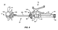
[0034]外科用システム10は、例えば、フルオープン外科的手順、経皮的技術やミニオープン外科技術を含む最小侵襲手順で採用され、図8および図9に示すような、例えば、椎骨Vを有する脊椎を含む患者の手術部位で、機器、および/または、例えば、椎体間インプラントなどの脊椎インプラント、を送達および導入する。実施形態によっては、脊椎インプラントは、ケージ、スペーサ、椎骨デバイス、骨締結体、脊椎ロッド、コネクタおよび/または板などの1つまたは複数の脊椎構造体の1つまたは複数の構成要素を含む場合がある。
[0034]
[0035]外科用システム10は、例えば、インサータ12などの外科用機器を含む。インサータ12は、例えば、縦軸A1を画定するボディ14などの部材を含む。ボディ14は、端部16および端部18間に延びる。ボディ14は、外側スリーブ20を含む。実施形態によっては、外側スリーブ20の1つまたは複数の部分は、管状、中実であることがあり、および/または、インサータ12の構成要素の配設のためのキャビティを画定することがある。
[0035] The
[0036]外側スリーブ20は、ハンドル22およびシャフト24を含む。ハンドル22は、端部26および端部28間に延びる。実施形態によっては、ハンドル22は、例えば、楕円形、長円形、三角形、四角形、六角形、多角形、不規則、均一、不均一、および/または、先細などの代替の断面構成を有することがある。実施形態によっては、ハンドル22は、本明細書で説明するように、シャフト24と共に組み立てられることがある。実施形態によっては、ハンドル22は、シャフト24と共にモノリシックに形成されることがある。実施形態によっては、ハンドル22は、例えば、横断、平行、垂直、ならびに/あるいは、鋭角もしくは鈍角、同軸、オフセット、および/または、千鳥状などの他の角度配向などの、シャフト24に対して代替の配向で配設されることがある。
[0036] The
[0037]ハンドル22は、キャビティ32を画定する表面30を含む。キャビティ32は、例えば、シャフト34などの縦部材の配設のために構成される。シャフト34は、本明細書で説明するように、脊椎インプラント150をインサータ12と連結するように構成される。ハンドル22は、本明細書で説明するように、脊椎インプラント150の操作、移動、並進、および/または、回転を容易にするように構成される。ハンドル22は、本明細書で説明するように、旋回グリップ40およびノブ60を含むアクチュエータを含む。
[0037] The
[0038]グリップ40は、端部42および端部44間に延びる。実施形態によっては、グリップ40は、複数の配向で保持されるように人間工学的に設計される。実施形態によっては、グリップ40は、グリップ40の操作を容易にするように構成されたぎざぎざを含む。グリップ40は、端部42がピン46によってハンドル22に連結される。端部44は、本明細書で説明するように、ハンドル22に対してグリップ40のロックおよびアンロックを容易にするように構成されたフランジ48を含む。
[0038] The grip 40 extends between the
[0039]グリップ40は、軸A1に対してピン46のまわりを回転および/または旋回するように構成される。グリップ40は、シャフト34に対するグリップ40の、図2に示すようなロック配向と、図3に示すようなノンロック配向と、の間でピン46のまわりを回転する。グリップ40のロックは、シャフト34の並進を阻止および/または防止し、したがって、例えば、脊椎インプラント150は、本明細書で説明するように、端部18に対して選択された固定位置に配設される。グリップ40をノンロック配向に回転させることは、本明細書で説明するように、ボディ14に対してシャフト34の移動および/または並進を可能にさせ、端部18に対して脊椎インプラント150の移動および/または回転を容易にする。実施形態によっては、グリップ40は、軸A1に対して0〜90度の角度範囲を通して回転することがある。実施形態によっては、グリップ40は、例えば、中実、管状、アーチ状、オフセット、千鳥状、均一および不均一などの様々な構成を有することがある。
[0039] The grip 40 is configured to rotate and / or swivel around a
[0040]実施形態によっては、グリップ40は、図4に示すように、例えば、ピン46のまわりに配設されたトーションばね49などの付勢部材を含む。ばね49は、グリップ40およびボディ14と連結される脚部を含む。そういうことで、ばね49は、本明細書で説明するように、付勢力をグリップ40に適用して、グリップ40をノンロック配向に強要する。グリップ40は、本明細書で説明するように、操作可能であり、ばね49の付勢力に打ち勝って、ロック配向に配設するためにグリップ40を旋回および/または回転させる。実施形態によっては、グリップ40は、付勢部材なしで手動で操作可能であることがある。
[0040] In some embodiments, the grip 40 includes an urging member such as a torsion spring 49 disposed around a
[0041]実施形態によっては、本明細書で説明するような付勢部材は、ばね、円錐ばねワッシャ、ディスクばね、ベルビルばね、カップ状ばねワッシャ、コイルばね、エラストマ部材、クリップ、板ばね、重力誘導構成、ニューマチック構成、ハイドローリック構成および/または手動レバーを含む。実施形態によっては、付勢部材は、半剛性、剛性、または弾性の構成を有することがあり、ならびに/あるいは、上で説明した材料例に対応する弾性特性などの弾性特性を有することがあり、したがって、付勢部材は、選択した位置および配向間の移動の選択的な量を提供する。実施形態によっては、付勢部材は、複数の別々に取り付け可能ないし連結可能な、バンドやループなどの部分またはセクションを含むことがあり、あるいは、単一の連続的な要素としてモノリシックに形成されることがある。実施形態によっては、付勢部材は、例えば、可撓性シャフトなどの軸要素を含む。実施形態によっては、付勢部材は、固体ディスクまたは球形状を有する。 [0041] In some embodiments, the urging members as described herein include springs, conical spring washers, disc springs, bellville springs, cup-shaped spring washers, coil springs, elastoma members, clips, leaf springs, gravity. Includes inductive configuration, pneumatic configuration, hydraulic configuration and / or manual lever. In some embodiments, the urging member may have a semi-rigid, rigid, or elastic configuration and / or may have elastic properties such as elastic properties corresponding to the material examples described above. Therefore, the urging member provides a selective amount of movement between selected positions and orientations. In some embodiments, the urging member may include multiple separately attachable or connectable parts or sections such as bands or loops, or may be monolithically formed as a single continuous element. Sometimes. In some embodiments, the urging member includes a shaft element such as a flexible shaft. In some embodiments, the urging member has a solid disc or spherical shape.
[0042]ハンドル22は、ハンドル22に対してロック配向およびノンロック配向での配設のための、例えば、グリップ40に係合するように構成されたカラー50などのロックを含む。カラー50は、例えば、カットアウト52などのキャビティを含む。カットアウト52は、本明細書で説明するように、グリップ40のノンロック配向への移動を容易にするように構成される。カラー50は、図1に示すような、フランジ48がカラー50内に配設されてカラー50がハンドル22に対してグリップ40の旋回を阻止および/または防止するような、ロック配向と、図3に示すような、フランジ48がそれを通してハンドル22に対して移動のためにカットアウト52と整列するような、ノンロック配向と、の間を時計回り方向および反時計回り方向に回転可能である。フランジ48に対するカットアウト52の整列は、グリップ40が、カットアウト52を通過させることによって、カラー50から係合解除するのを可能にする。カラー50からのグリップ40の係合解除は、ハンドル22に対してグリップ40の旋回を可能にする。グリップ40は、本明細書で説明するように、外科的手順中に脊椎インプラント150の回転を阻止および/または防止するように構成される。
[0042] The
[0043]ノブ60は、端部26がハンドル22と連結される。ノブ60は、本明細書で説明するように、時計回り方向および反時計回り方向に回転可能であり、脊椎インプラント150を選択した配向まで移動および/または回転させるために、シャフト34の移動および/または並進を容易にする。シャフト34は、端部62および端部64間に延びる。
[0043] The end portion 26 of the
[0044]端部62は、ノブ60と係合可能であり、したがって、ノブ60の回転は、端部18に対して移動および/または回転のために、シャフト34を脊椎インプラント150に係合させる。実施形態によっては、シャフト34は、ピンによってノブ60と連結される。実施形態によっては、シャフト34は、ねじ式係合によってノブ60と連結される。シャフト34は、周方向フランジ65を画定する表面63を含む。フランジ65は、グリップ40のロック配向でのフランジ148との係合のために構成され、ハンドル22に対してシャフト34の並進を阻止および/または防止する。グリップ40のロック配向での係合時に、フランジ148は、力を嵌合係合のフランジ65に適用して、力および/または圧力をシャフト34に適用する。この力は、ハンドル22に関連してシャフト34の位置を固定し、および/または、端部18および脊椎インプラント150間の圧力嵌合を形成する。この構成は、端部18に対して脊椎インプラント150の移動および/または回転を阻止および/または防止する。フランジ148は、ノンロック配向のシャフト34の配設のために、フランジ65から係合解除する。フランジ65からのフランジ148の係合解除は、嵌合係合、および/または、端部18および脊椎インプラント150間の圧力嵌合、を解放して、端部18に対して脊椎インプラント150の移動および/または回転を可能にする。実施形態によっては、グリップ40は、選択的にロック配向およびノンロック配向に配設されて、端部18に対して脊椎インプラント150を選択的に固定および操作、移動、並進、回転、および/または、位置調整し、したがって、グリップ40のロックは、組織に対する脊椎インプラント150の位置決めのための1つまたは複数の繰り返しのために、適用、解放、および/または、再適用される場合がある。実施形態によっては、グリップ40は、選択的にロック配向およびノンロック配向に配設されて、端部18に対しておよびそのまわりに0〜360度の角度範囲で脊椎インプラント150を選択的に固定および位置調整する。実施形態によっては、グリップ40は、選択的にロック配向およびノンロック配向に配設されて、例えば、図1に関して本明細書で図示および説明するような挿入または送達の配向と、図3に関して本明細書で図示および説明するようなインプラント配向と、の間の脊椎インプラント150の移動の範囲において、端部18に対して脊椎インプラント150を選択的に固定および操作、移動、並進、回転、および/または、位置調整する。
[0044] The end 62 is engageable with the
[0045]端部64は、本明細書で説明するように、脊椎インプラント150に配設される可動ピン156と嵌合係合するために構成された表面66を含む。実施形態によっては、端部64は、ノブ60の作動の際にピン156とねじ式係合するために構成される。ノブ60の作動は、本明細書で説明するように、シャフト34に脊椎インプラント150を引かせて端部18に係合させ、手術部位への送達のために、脊椎インプラント150を端部18に固定させる。実施形態によっては、表面66は、例えば、溝付き、粗面、ディンプル付き、研摩付き、テクスチャ付きなどの脊椎インプラント150の表面と嵌合係合するための代替の表面構成、および/または、四角形、三角形、六角形、多角形、星形、トルクスまたはヘキサローブの断面を含むことがあるドライブもしくはソケット、を有することがある。
[0045] The end 64 includes a surface 66 configured for mating engagement with a
[0046]実施形態によっては、ハンドル22は、図5に示すように、端部28に配設される嵌合キャビティ68を含む。実施形態によっては、嵌合キャビティ68は、本明細書で説明するように、四角形、三角形、六角形、多角形、星形、トルクスまたはヘキサローブの断面を含むことがあり、シャフト24に配設される嵌合表面92を画定する表面の対応形状付け部分に係合するように構成される。
[0046] In some embodiments, the
[0047]ボディ14は、本明細書で説明するように、ナビゲーション構成要素70を含む画像ガイドとの連結のために構成される。ナビゲーション構成要素70は、インサータ12の位置を表す信号を発生させるように構成される。実施形態によっては、本明細書で説明するような画像ガイドは、人間の読み取れる視覚的しるし、人間の読み取れる触覚的しるし、人間の読み取れる聴覚的しるし、X線、蛍光透視、CTまたは他の撮像技術の下での識別のためのマーカを有する1つまたは複数の構成要素、少なくとも1つの発光ダイオード、無線構成要素、有線構成要素、近距離無線通信構成要素、ならびに/あるいは、音響信号、磁気信号、電磁信号および/または放射線学的信号を発生させる1つまたは複数の構成要素、を含むことがある。
[0047] The
[0048]ナビゲーション構成要素70は、ボディ14の一部分に配設するために構成されたカラー72を含む。実施形態によっては、カラー72は、ボディ14で固定される。実施形態によっては、カラー72は、ボディ14に対して軸A1のまわりを回転可能である。実施形態によっては、カラー72は、摩擦嵌合、圧力嵌合、インターロック係合、嵌合係合、ダブテール連結、フックアンドループクロージャ、クリップ、バーブ、溝内トング、ねじ切り、磁気、キー/キースロット、ドリルチャックおよび/または接着剤、を介して、ボディ14と連結される。
[0048] The
[0049]カラー72は、そこから延びる柱80を含む。柱80は、軸X1を画定する。柱80は、軸A1に垂直に延び、軸A1のまわりをカラー72と共に回転可能である。実施形態によっては、軸X1は、例えば、平行、横断および/または鋭角もしくは鈍角などの他の角度配向などの軸A1に対して代替の配向で配設されることがある。
[0049] The
[0050]ナビゲーション構成要素70は、柱80を介してカラー72に連結されるエミッタアレイ82を有するトラッキングデバイスを含む。実施形態によっては、柱81は、キャビティ81を含む。実施形態によっては、キャビティ81は、エミッタアレイ82をカラー72と連結するように構成されたねじ付きスクリュ83を受け入れるように構成される。エミッタアレイ82は、軸A1のまわりをカラー72と共に回転可能である。実施形態によっては、エミッタアレイ82は、例えば、平行、垂直、横断および/または鋭角もしくは鈍角などの他の角度配向などの軸A1に対して代替の配向で配設されることがある。
[0050]
[0051]エミッタアレイ82は、図7に示して本明細書で説明するように、センサアレイ202への信号を発生させるために構成されており、3次元の空間位置、ならびに/あるいは、患者の解剖学的構造の一部分に関連したインサータ12および/または脊椎インプラント150の軌道、ならびに/あるいは、モニタ上の表示のための患者の解剖学的構造内のインサータ12および/または脊椎インプラント150の深さ、を表す。エミッタアレイ82は、実質上X形状を有する4つの離隔されたアームを含む。エミッタアレイ82は、例えば、起点84などのマーカを含む。起点84は、基準または測定の点として使用するために外科用システム10の外科用ナビゲーションシステム200によって作り出される画像に現れる。エミッタアレイ82は、患者の解剖学的構造の様々なボディ基準点の位置を表す信号を発生させる。実施形態によっては、起点84は、少なくとも1つの発光ダイオードを含む。実施形態によっては、起点84は、例えば、音響信号、磁気信号、電磁信号および/または放射線学的信号を能動的に発生させるトラッキングデバイスなどのセンサアレイ202がトラッキングすることのできる他のトラッキングデバイスを含むことがある。実施形態によっては、起点84は、エミッタアレイ82に除去可能に取り付けられることがある。実施形態によっては、1つまたは複数の起点84は、個々が単一のボール形状のマーカを含む。
The implant array 82 is configured to generate a signal to the
[0052]シャフト24は、ハンドル22から遠位に延びて、端部18を含む。シャフト24は、端部90を含む。端部90は、嵌合表面68との嵌合係合のために構成されたキャビティ92を含む。実施形態によっては、キャビティ92は、例えば、楕円形、長円形、三角形、矩形、四角形、多角形、不規則、均一、不均一、可変、管状、および/または、先細などの様々な断面構成を有することがある。
[0052] The
[0053]シャフト24は、例えば、軸チャネル96などのキャビティを画定する表面94を含む。チャネル96は、端部98および端部100間に延びる。チャネル96は、例えば、ロッド102などの縦要素の配設のために構成される。ロッド102は、チャネル96内を延びており、インサータ12に対する取り付け時に端部18および脊椎インプラント150に隣接して配設される端部104および端部106を含む。
[0053] The
[0054]本明細書で説明するように、ロッド102は、シャフト24に対して並進のために構成され、その理由は、脊椎インプラント150が組織に対する位置決めのために移動および/または回転するからであり、例えば、椎間空間などの組織に対する脊椎インプラント150の操作、移動、並進および/または回転の量のしるしおよび/または表示を提供するためである。実施形態によっては、ロッド102は、例えば、楕円形、長円形、三角形、四角形、六角形、多角形、不規則、均一、不均一、および/または、先細などの代替の断面構成を有することがある。
[0054] As described herein, the
[0055]実施形態によっては、ロッド102は、例えば、ロッド102のキャビティ内に実装されてボディ14に係合可能であるコイルばね110などの付勢部材を含む。ばね110は、本明細書で説明するように、付勢力をロッド102に適用して、ロッド102を挿入または送達の配向に強要する。端部18が挿入または送達の配向で脊椎インプラント150と連結され、ハンドル22およびシャフト34がロック配向で配設される場合、本明細書で説明するように、脊椎インプラント150は、インサータ12で固定される。本明細書で説明するように、端部18は、脊椎インプラント150と固定され、端部106は、脊椎インプラント150の表面に係合し、端部18および/または脊椎インプラント150のしるしおよび/または表示を提供する。
[0055] In some embodiments, the
[0056]端部104は、画像ガイド120を含む。画像ガイド120は、本明細書で説明するように、角度ゲージ122およびナビゲーション構成要素180を含む。ゲージ122は、本明細書で説明するように、配向、例えば、図8に示すような送達配向と、配向、例えば、図9に示すようなインプラント配向と、の間の角度の変化を測定する。画像ガイド120は、脊椎インプラント150の選択した相対配向間の角度の変化の角度測定値を表し、表示する。
[0056] The
[0057]ゲージ122は、図5に示すように、端部124および端部126間に延びる。ゲージ122は、本明細書で説明するように、シャフト24に対して回転する。端部124は、リング128を含み、このリングは、ピボットまたはピン130のまわりに配設され、シャフト24に対してゲージ122の回転を容易にするように構成される。実施形態によっては、ピン130は、ロッド102と固定される。実施形態によっては、リング128は、シャフト24に対してゲージ122の回転を容易にするために、実質上無摩擦係合でピン130に配設される。実施形態によっては、ピン130は、ゲージ122と固定され、シャフト24に対して回転可能であり、したがって、ゲージ122は、シャフト24に対して回転する。ゲージ122は、本明細書で説明するように、ロッド102の並進に応答してリング128を介してピン130のまわりを旋回し、したがって、ゲージ122は、ピン130のまわりを回転する。
[0057]
[0058]ゲージ122は、アーチ状セクション132、134を含む。セクション132、134は、離隔関係で配設される。セクション132は、トラック138を画定する表面136を含む。セクション134は、トラック142を画定する表面140を含む。トラック138、142は、図2および図3に示すように、例えば、ロッド102に配設されるマーカ144などの部材の移動可能な配設のために構成される。
[0058]
[0059]実施形態によっては、マーカ144は、初期配向、例えば、脊椎インプラント150の送達配向からロッド102と共に軸方向に移動および/または並進され、この配向は、マーカ144および/またはゲージ122の静止、ゼロ角度または較正の配向を示す。初期配向から、ロッド102は、脊椎インプラント150に係合して、脊椎インプラント150を操作、移動、並進および/または回転させ、したがって、マーカ144は、ロッド102と共に軸方向に移動および/または並進する。実施形態によっては、本明細書で説明するように、ゲージ122および/またはマーカ144は、シャフト24に対してピン130のまわりを回転し、インサータ12および/または組織に対してゲージ122および脊椎インプラント150の角度配向の変化を測定する。実施形態によっては、ロッド102は、ばね110の付勢力に打ち勝つために近位方向に並進する。実施形態によっては、ロッド102は、組織に対する脊椎インプラント150の位置決めのために、インプラント配向の近位方向および遠位方向に並進することがある。実施形態によっては、そういった並進は、ゲージ122を静止および/または平衡状態から回転させ、重力に起因する回復力は、ゲージ122に従属する。
[0059] In some embodiments, the
[0060]マーカ144は、ゲージ112をピン130のまわりに旋回または回転させ、したがって、マーカ144は、トラック138、142に沿って移動して、初期配向に対して脊椎インプラント150のインプラント配向の測定した角度を示す。実施形態によっては、ゲージ122は、マーカ144に対して回転し、したがって、マーカ144は、しるし146と整列され、挿入中に脊椎インプラント150の角度差の角度測定値を表し、表示する。実施形態によっては、セクション132および/またはセクション134は、本明細書で説明するように、角度測定値を代表および表示する情報を有するしるし146を含む。ピン130は、ゲージ122およびマーカ144をシャフト24に連結する。
[0060] The
[0061]実施形態によっては、しるし146は、セクション132および/またはセクション134の表面に沿って配設された目盛付きマーキングを含む。実施形態によっては、マーキングは、本明細書で説明するように、ゲージ122によって測定された角度を測定し、選択し、調整し、および/または表示する角度範囲に関する情報を表示し、表し、および/または提供する。実施形態によっては、マーキングは、等距離に離隔されてしるし146の測定した角度増分に対応する両側配設溝を含むことがある。
[0061] In some embodiments, the
[0062]実施形態によっては、しるし146は、角度10度の増分で配設されることがあるマーキングを含む。実施形態によっては、しるし146は、例えば、角度の数値インジケータ付きダイアルなどのアナログ、ならびに/あるいは、例えば、LEDおよび/またはLCDなどのデジタルディスプレイ、を含むことがある。実施形態によっては、しるし146は、例えば、ラベル、カラーコーディング、英数字またはアイコンなどの人間の読み取れる視覚的しるしを含む。実施形態によっては、しるし146は、例えば、隆起部分、下降部分または点字などの人間の読み取れる触覚的しるしを含む。実施形態によっては、しるし146は、スロットや溝と組み合わせた印刷または書込みアイテムであり、それによって印刷または書込みアイテムは、スロットもしくは溝に配置されて情報を表示する。実施形態によっては、しるし146は、接着剤として適用されることがある。
[0062] In some embodiments, the marking 146 includes markings that may be arranged in increments of 10 degrees. In some embodiments, the
[0063]実施形態によっては、ゲージ122および/またはマーカ144および/またはしるし146は、ポリマなどの放射線透過性材料を含む。ラジオマーカは、X線、蛍光透視、CTまたは他の撮像技術の下で識別のために含まれることがある。実施形態によっては、ナビゲーション構成要素180は、端部106、端部18および/または脊椎インプラント150の角度位置を表す信号を発生させるように構成される。実施形態によっては、ナビゲーション構成要素180は、脊椎インプラント150が回転すると信号を発生させるように構成される。ナビゲーション構成要素180は、起点182を含む。起点182は、基準または測定の点として使用するために外科用ナビゲーションシステム200によって作り出される画像に現れる。起点182は、ゲージ122の位置決めと、脊椎インプラント150の角度位置と、を表す信号を発生させる。実施形態によっては、起点182は、組織に対して選択した配向まで回転される脊椎インプラント150の位置を表す信号を発生させる。実施形態によっては、起点182は、例えば、横断平面などのボディの選択した平面を表す信号を発生させる。実施形態によっては、起点182は、少なくとも1つの発光ダイオードを含む。実施形態によっては、起点182は、例えば、音響信号、磁気信号、電磁信号、放射線学的信号を能動的に発生させるトラッキングデバイスなどのセンサアレイ202がトラッキングすることのできる他のトラッキングデバイスを含むことがある。実施形態によっては、起点182は、ロッド102に除去可能に取り付けられることがある。実施形態によっては、起点182は、単一のボール形状のマーカを含むことがある。実施形態によっては、起点182は、1つまたは複数のマーカを含むことがある。
[0063] In some embodiments, gauges 122 and / or
[0064]ナビゲーション構成要素180は、ゲージ122に配設されて回転可能であり、しるしを提供する、ならびに/あるいは、角度配向、および/または、インサータ12に対して脊椎インプラント150の軌道、患者の解剖学的構造の一部分、および/または、患者の解剖学的構造内の端部18および/または脊椎インプラント150の深さ、を表示する。ロッド102は、シャフト24に対して配向され、ボディ14に対して近位位置および遠位位置間の脊椎インプラント150の表面と係合可能であり、したがって、起点182は、角度的しるしおよび/または脊椎インプラント150の表示を提供する。
[0064] The navigation component 180 is located on the
[0065]端部106は、脊椎インプラント150の表面に隣接する配設のために構成され、したがって、脊椎インプラント150の回転は、図8および図9に示すように、ロッド102をチャネル96内で並進させる。ロッド102の並進は、起点182を回転させて、脊椎インプラント150の位置、移動および/または回転を示す。
[0065] The
[0066]実施形態によっては、ロッド102の近位位置は、図8に示すような、端部18と連結されて挿入または送達の配向で配設されている脊椎インプラント150に対応する。実施形態によっては、挿入または送達の配向では、脊椎インプラント150は、シャフト24と軸方向に整列して配設される。実施形態によっては、ロッド102の遠位位置は、図9に示すような、端部18と連結されてインプラント配向で配設されている脊椎インプラント150に対応する。実施形態によっては、2次元の空間位置および/または軌道は、例えば、横断平面などの患者の解剖学的構造の平面を含む。
[0066] In some embodiments, the proximal position of the
[0067]脊椎インプラント150は、椎骨係合表面152および椎骨係合表面154を含む。実施形態によっては、脊椎インプラント150の断面ジオメトリは、例えば、丸形、楕円形、長円形、三角形、平面状もしくはアーチ状の側面部分を有する多角形、不規則、均一、不均一、一貫した、可変、蹄鉄形状、U形状またはインゲン豆形状などの様々な構成を有することがある。実施形態によっては、表面152、154は、円滑、平ら、粗い、テクスチャ付き、多孔性、半多孔性、ディンプル付きおよび/または研摩付きであることがある。
[0067] The
[0068]実施形態によっては、脊椎インプラント150は、端部18に対して脊椎インプラント150の回転および/または旋回を容易にするためにピン156の配設のために構成されたキャビティを含む。ピン156は、シャフト34の端部64との係合のために構成された表面を含む。実施形態によっては、ピン156は、ねじ66と嵌合するねじ付き内側表面を含み、組織に対する脊椎インプラント150の位置決めのための脊椎インプラント150のインサータ12との連結を容易にする。
[0068] In some embodiments, the
[0069]実施形態によっては、脊椎インプラント150は、選択した角度範囲を通じてピン156に対して回転可能である。実施形態によっては、脊椎インプラント150は、ピン156に対して選択的に回転可能である。実施形態によっては、脊椎インプラント150は、ピン156に対して受動的に回転可能であり、したがって、椎骨空間での脊椎インプラント150の挿入中の脊椎インプラント150と連結されたインサータ12の操作は、端部18との係合および組織の抵抗に起因して、ピン156に対して脊椎インプラント150を回転させる。
[0069] In some embodiments, the
[0070]インサータ12は、手術部位に隣接する配設のために構成され、したがって、ナビゲーション構成要素70および/またはナビゲーション構成要素180は、本明細書で説明するように、センサアレイ202に対して配向され、外科的手順中のナビゲーション構成要素70および/またはナビゲーション構成要素180とセンサアレイ202との間の通信が容易にされる。実施形態によっては、センサアレイ202は、ナビゲーション構成要素70から信号を受け取り、3次元の空間位置、あるいは/ならびに、患者の解剖学的構造の一部分に関連したインサータ12および/または脊椎インプラント150の軌道、ならびに/あるいは、モニタ上の表示のための患者の解剖学的構造内のインサータ12および/または脊椎インプラント150の深さ、を提供する。実施形態によっては、センサアレイ202は、ゲージ122に配設されるナビゲーション構成要素180から信号を受け取り、端部106、端部18および/または脊椎インプラント150、の角度位置を提供する。例えば、米国特許第6,021,343号、第6,725,080号、第6,796,988号で説明されているような、同様の外科用ナビゲーション構成要素およびそれらの使用を参照のこと。
[0070] The
[0071]外科用ナビゲーションシステム200は、図7に示すような、例えば、所与の外科的手順に相応しいX線画像などの医療撮像を取得および表示するために構成される。実施形態によっては、患者の事前取得した画像は、収集される。実施形態によっては、外科用ナビゲーションシステム200は、米国コロラド州ルイビルに事業所を有するMedtronic Navigation,Inc.の販売するO−arm(登録商標)撮像デバイス204を含む場合がある。撮像デバイス204は、画像キャプチャ部分208を囲む略環状のガントリハウジングを有することがある。
The
[0072]実施形態によっては、画像キャプチャ部分208は、X線源または放射部分とX線受容または画像受容部分とを含むことがあり、それらは、互いに対して概略または実質上可能な180度に位置し、画像キャプチャ部分208のトラックに対してロータ(図示せず)上に実装される。画像キャプチャ部分208は、画像取得中に360度回転するために動作可能である場合がある。画像キャプチャ部分208は、中央点または軸のまわりを回転することがあり、患者の画像データを複数の方向からまたは複数の平面で取得することを可能にする。外科用ナビゲーションシステム200は、米国特許第8,842,893号、第7,188,998号、第7,108,421号、第7,106,825号、第7,001,045号、および、第6,940,941号に開示されたものを含む場合がある。
[0072] In some embodiments, the
[0073]実施形態によっては、外科用ナビゲーションシステム200は、患者の3次元ビューを生成することのできるCアーム蛍光透視撮像システムを含む場合がある。画像キャプチャ部分208の位置は、撮像デバイス204の任意の他の部分に対して正確に認識することができる。実施形態によっては、画像キャプチャ部分208の位置の正確な認識は、画像キャプチャ部分208の位置および患者に関連する画像データを決定するために、トラッキングシステム210と共に使用される場合がある。
[0073] In some embodiments, the
[0074]トラッキングシステム210は、外科用ナビゲーションシステム200と関係があるまたはそれに含まれる様々な部分を含む場合がある。実施形態によっては、トラッキングシステム210は、例えば、センサアレイ202などの光学ローカライザを含む、例えば、光学トラッキングシステム、ならびに/あるいは、EMローカライザを含む場合があるEMトラッキングシステム、などの複数のタイプのトラッキングシステムを含む場合もある。様々なトラッキングデバイスは、トラッキングシステム210を用いてトラッキングされる場合があり、情報は、例えば、患者トラッキングデバイス214、撮像デバイストラッキングデバイス216、および、例えば、ナビゲーション構成要素70、180などの機器トラッキングデバイスなどのアイテムの位置の表示を可能にするための外科用ナビゲーションシステム200によって使用される場合があり、適切なトラッキングシステムを用いて、選択した部分を互いに対してトラッキングすることを可能にする。
[0074] The
[0075]実施形態によっては、EMトラッキングシステムは、コロラド州ルイビルに事業所を有するMedtronic Navigation,Inc.の販売するSTEALTHSTATION(登録商標)AXIEM(商標)ナビゲーションシステムを含む場合がある。例示的なトラッキングシステムは、米国特許第8,057,407号、第5,913,820号、第5,592,939号にも開示されている。 [0075] In some embodiments, the EM tracking system is described by Medtronic Navigation, Inc., which has offices in Louisville, Colorado. May include STEALTHSTATION® AXIEM® navigation systems sold by. An exemplary tracking system is also disclosed in US Pat. Nos. 8,057,407, 5,913,820, 5,592,939.
[0076]得られた蛍光透視画像は、コンピュータ218に伝達され、そこでは外科用ナビゲーションコンピュータ220に転送されることがある。画像の移動は、標準ビデオコネクションまたは有線および無線を含むデジタルリンクによって実行されることがある。コンピュータ220は、モニタ222を介して表示する、ならびに、受け取った画像のハードコピーを保存、デジタル操作、または印刷する、能力を提供する。実施形態によっては、画像は、ヘッドアップディスプレイを通して、外科医に表示することもある。
[0076] The resulting fluoroscopic image is transmitted to
[0077]実施形態によっては、外科用ナビゲーションシステム200は、インサータ12および脊椎インプラント150のリアルタイムのトラッキングを提供する。センサアレイ202は、本明細書で説明するように、ナビゲーション構成要素70、180に対するクリアな視線を提供するように位置する。実施形態によっては、ナビゲーション構成要素70、180は、赤外線技術を介してセンサアレイ202と通信を行う。センサアレイ202は、ソフトウエアモジュールを用いてプログラミングされ得るコンピュータ220に連結され、このモジュールは、センサアレイ202によって伝達される信号を分析して検出器空間の各対象の位置を決定する。プロセッサは、情報をモニタ222に送り、モニタは、患者の解剖学的構造に対してインサータ12および脊椎インプラント150の位置の視覚的な表示を提供し、医療従事者がインサータ12および脊椎インプラント150を患者の解剖学的構造内の所望の場所まで移動させるのを可能にする。
[0077] In some embodiments, the
[0078]組立て、動作および使用では、外科用システム10は、本明細書で説明するシステムおよび方法と同様、本明細書で議論するように、患者の脊椎のセクションに影響する脊椎障害の処置のための外科的手順で採用される。例えば、外科用システム10の構成要素は、図8および図9に示すように、椎骨Vを含む脊椎の患部セクションのコンディションや怪我の処置のために外科的手順で使用される場合がある。実施形態によっては、外科用システム10の1つまたはすべての構成要素は、事前組立て型デバイスとして送達または埋込みされる場合があり、あるいは、現場で組立てされる場合がある。外科用システム10は、完全にまたは部分的に、改訂、除去または交換を行うことがある。
[0078] In assembly, operation and use, the
[0079]外科用システム10の構成要素は、例えば、椎骨Vなどの、ボディ内の脊柱の患部セクションや隣接するエリアの適用できるコンディションおよび怪我の外科的処置で採用される場合がある。実施形態によっては、外科用システム10の構成要素は、例えば、椎骨V1および椎骨V2などの1つまたは複数の椎骨で採用されることがある。椎骨Vの選択したセクションを処置するために、医療従事者は、組織の切開および開創を通してなどの任意の適切なやり方で椎骨Vを含む手術部位へのアクセスを取得する。実施形態によっては、外科用システム10の構成要素は、オープン手術、ミニオープン手術、最小侵襲手術、および経皮的外科移植を含む任意の既存の外科的方法または技術で使用される場合があり、それによって、椎骨Vが、ミニ切開、または、エリアへの保護された通路を提供するスリーブを通してアクセスされる。ひとたび手術部位へのアクセスが取得されると、特定の外科的手順は、脊椎障害を処置するために実行される場合がある。
[0079] The components of the
[0080]切開は、患者のボディで行われ、切削機器(図示せず)は、例えば、椎骨V1および椎骨V2などの患者のボディ内のエリアに隣接する本明細書で説明するようなインサータ12を含む外科用システム10の構成要素の送達のための外科的経路を作り出す。実施形態によっては、調製機器(図示せず)は、椎間板組織、体液、隣接する組織および/または骨を除去するため、ならびに、組織を椎骨V1の終板表面および/または椎骨V2の終板表面から擦り取るおよび/または除去するため、採用される。実施形態によっては、脊椎インプラント150の寸法は、試用後に選択される。実施形態によっては、脊椎インプラント150は、蛍光透視によって視覚化されて、椎骨空間の中への導入前に配向される。
[0080] The incision is made in the patient's body and the cutting instrument (not shown) is an
[0081]インサータ12は、本明細書で説明するように挿入または送達の配向で配設するために、本明細書で説明するように脊椎インプラント150と連結される。グリップ40は、ノンロック配向で初期に配設され、図8に示して本明細書で説明するように、ロック配向までのピン46のまわりの回転のために操作される。カラー50は、本明細書で説明するように、ロック配向で配設される。ノブ60は、回転して、シャフト34をピン156に係合させ、脊椎インプラント150を本明細書で説明するようにインサータ12と連結させ、端部18、106を引いて脊椎インプラント150と係合させる。
[0081] The
[0082]脊椎インプラント150は、端部18に対して選択された固定位置に配設され、したがって、脊椎インプラント150は、シャフト24と軸方向に整列される。インサータ12は、操作されて、脊椎インプラント150を椎骨V1、V2間の椎骨空間に送達する。センサアレイ202は、ナビゲーション構成要素70から信号を受け取り、3次元の空間位置、ならびに/あるいは、椎骨V1、V2間の椎骨空間に関連したインサータ12および/または脊椎インプラント150の軌道、ならびに/あるいは、モニタ222上の表示のための椎骨空間内のインサータ12および/または脊椎インプラント150の深さ、を提供する。
[0082] The
[0083]インサータ12は、図8に示すように、脊椎インプラント150を椎骨V1、V2間の椎骨空間に選択的に配設する。端部18が挿入または送達の配向で脊椎インプラント150と連結される場合、端部106は、本明細書で説明するように、脊椎インプラント150の表面に係合して、端部18および/または脊椎インプラント150のしるしおよび/または表示を起点182との関連で提供する。カラー50は、本明細書で説明するように、ノンロック配向まで回転する。グリップ40は、図9に示して本明細書で説明するように、ピン46のまわりの、ノンロック配向までの回転のために、解放される。端部18、106間の圧力嵌合は、解放され、脊椎インプラント150は、端部18、106に対して、移動可能および/または回転可能である。
[0083] As shown in FIG. 8, the
[0084]インサータ12の操作は、本明細書で説明するように、脊椎インプラント150に、椎骨V1、V2間の椎骨空間の定位置への、移動および/またはピン156のまわりの回転、を行わせる。脊椎インプラント150が、脊椎インプラント150を椎骨V1、V2間の椎骨空間に対して位置決めするためのインプラント配向で、操作、移動、並進および/または回転されるとき、脊椎インプラント150は、ロッド102と係合し、したがって、ロッド102は、近位方向に並進する。そういった並進は、本明細書で説明するように、ゲージ122に、ピン130まわりの回転を行わせて、マーカ144をしるし146と整列させ、脊椎インプラント150を椎骨V1、V2間の椎骨空間に対して位置決めするためのインプラント配向の測定した角度を、挿入または送達の配向に対して、示す。
[0084] The operation of the
[0085]実施形態によっては、しるし146は、ゲージ122を見る従事者によって視覚的に読み取られる。実施形態によっては、センサアレイ202は、信号をナビゲーション構成要素180から受け取って、例えば、椎骨Vの横断平面内での端部106、端部18および/または脊椎インプラント150の角度位置を提供する。実施形態によっては、グリップ40のロックおよびアンロックは、インプラント配向での脊椎インプラント150の選択的な移動および/または回転を可能にする。
[0085] In some embodiments, the
[0086]インサータ12は、脊椎インプラント150から係合解除される。実施形態によっては、脊椎インプラント150は、椎体間の高さ修復、減圧、矢状面バランスおよび/または冠状面バランスの修復、ならびに/あるいは、椎骨終板の陥没抵抗性を提供する。実施形態によっては、外科用システム10は、複数の脊椎インプラント150を含む。実施形態によっては、複数の脊椎インプラント150を採用することは、関節の隙間の大きさが事前選択できるように離隔され得る椎骨空間の量を最適化することができる。複数の脊椎インプラント150は、並列係合、離隔および/または千鳥配置によって側面に配向される場合がある。
[0086] The
[0087]実施形態によっては、外科用システム10は、例えば、インサータ、エクステンダ、レジューサ、スプレッダ、伸延器、ブレード、開創器、クランプ、鉗子、昇降器およびドリルなどの本開示の構成を含む様々な機器を含むことがあり、それらは代替的に寸法決めされて必要な大きさにされ、また、キットとして配列されることがある。
[0087] Depending on the embodiment, the
[0088]実施形態によっては、外科用システム10は、外科用システム10の構成要素および/または表面の内部、上もしくはまわりに配設、梱包または積層され得る物質を含む。実施形態によっては、物質は、椎骨Vとの固定を高めるために、例えば、骨移植片などの骨成長促進材料を含むことがある。外科用システム10の構成要素は、ポリマなどの放射線透過性材料で作られる場合がある。ラジオマーカは、X線、蛍光透視、CTまたは他の撮像技術の下での識別のために含められることがある。実施形態によっては、物質は、例えば、疼痛、炎症および変性を処置するために、持効性解放を含む解放のための1つまたは複数の治療的物質および/または薬理学的物質を含むことがある。手順を完了すると直ぐに、外科用システム10の外科用機器、組立体および非埋込み式の構成要素は、手術部位から取り外されて、切開が閉じられる。
[0088] In some embodiments, the
[0089]図10〜図13に示すように、1つの実施形態では、図1〜図9に関して上で説明するシステムおよび方法と同様の外科用システム10は、インサータ312を含む。インサータ312は、本明細書で説明するボディ14と同様の、縦軸A2を画定するボディ314を含む。ボディ314は、端部316および端部318間に延びる。ボディ314は、外側スリーブ320を含む。外側スリーブ320は、本明細書で説明するハンドル22と同様のハンドル322を含む。外側表面320は、本明細書で説明するシャフト24と同様のシャフト324を含む。実施形態によっては、ハンドル322は、本明細書で説明するように、シャフト324と組み立てられる場合がある。
[0089] As shown in FIGS. 10-10, in one embodiment, a
[0090]ハンドル322は、本明細書で説明するシャフト34と同様のシャフト334の配設のために構成されたキャビティ332を含む。シャフト334は、本明細書で説明する脊椎インプラント150をインサータ312と連結するように構成される。ハンドル322は、本明細書で説明するように、脊椎インプラント150の操作、移動、並進および/または回転を容易にするように構成される。ハンドル322は、本明細書で説明するグリップ40と同様の旋回グリップ340を含むアクチュエータを含む。アクチュエータは、本明細書で説明するノブ60と同様のノブ360を含む。グリップ340は、本明細書で説明するフランジ48と同様、ハンドル322に対してグリップ340のロックおよびアンロックを容易にするように構成されたフランジ348を含む。
[0090] The
[0091]グリップ340は、シャフト334に対するグリップ340の、図11に示すようなロック配向と、図13に示すようなノンロック配向と、の間で、軸A2に対して回転および/または旋回するように構成される。グリップ340のロックは、シャフト334の並進を阻止および/または防止し、したがって、例えば、脊椎インプラント150は、本明細書で説明するものと同様、端部318に対して選択された固定位置に配設される。グリップ340をノンロック配向に回転することは、本明細書で説明するように、ボディ314に対してシャフト334の移動および/または並進を可能にして、端部318に対して脊椎インプラント150の移動および/または回転を容易にする。ハンドル322は、本明細書で説明するカラー50と同様のカラー350を含む。カラー350は、本明細書で説明するカットアウト52と同様のカットアウト352を含む。カットアウト352は、本明細書で説明するように、グリップ340のノンロック配向までの移動を容易にするように構成される。カラー350は、ハンドル322に対してロック配向およびノンロック配向の配設のためにグリップ340に係合するように構成される。実施形態によっては、本明細書で説明するグリップ40と同様のグリップ340は、選択的にロック配向およびノンロック配向に配設されて、端部318に対して脊椎インプラント150を選択的に固定および操作、移動、並進、回転、および/または、位置調整する。
[0091] The
[0092]ノブ360は、本明細書で説明するように、時計回り方向および反時計回り方向に回転可能であり、脊椎インプラント150を選択した配向まで移動および/または回転させるために、シャフト334の移動および/または並進を容易にする。ノブ360の作動は、本明細書で説明するように、シャフト334に脊椎インプラント150を引かせて端部318に係合させ、手術部位への送達のために、脊椎インプラント150を端部318に固定させる。
[0092] The
[0093]シャフト324は、ハンドル322から遠位に延びて、端部318を含む。シャフト324は、軸チャネル396を含む。チャネル396は、本明細書で説明するロッド102と同様に、ロッド402の配設のために構成される。ロッド402は、チャネル396内に延びており、インサータ312に対する取り付け時に端部318および脊椎インプラント150に隣接して配設される端部404および端部406を含む。本明細書で説明するように、ロッド402は、シャフト324に対して並進し、脊椎インプラント150は、例えば、椎間空間などの組織に対する位置決めのために、移動および/または回転する。ロッド402は、シャフト324と共に配向され、ボディ314に対して近位位置および遠位位置間で脊椎インプラント150の表面に係合可能である。
[0093]
[0094]実施形態によっては、ロッド402は、本明細書で説明するように、コイルばね114と同様の付勢部材を含み、付勢力をロッド402に適用して、ロッド402を挿入または送達の配向に強要する。端部404は、本明細書で説明するゲージ122と同様の角度ゲージ422を有する画像ガイド420を含む。ゲージ422は、脊椎インプラント150の選択した相対配向間の角度の変化の角度測定値を表し、表示する。ゲージ422は、本明細書で説明するように、シャフト24に対して回転する。ゲージ422は、本明細書で説明するように、マーカ444の移動可能な配設のために構成されたトラック438、442を含む。ゲージ422は、本明細書で説明するように、配向、例えば、送達配向と、配向、例えば、インプラント配向と、の間の脊椎インプラント150の角度配向の変化を測定する。
[0094] In some embodiments, the
[0095]端部318が挿入または送達の配向で脊椎インプラント150と連結され、ハンドル322およびシャフト334がロック配向で配設される場合、本明細書で説明するように、脊椎インプラント150は、インサータ312と固定される。端部318は、脊椎インプラント150と固定され、端部406は、脊椎インプラント150の表面に係合する。脊椎インプラント150が、脊椎インプラント150を組織に対して位置決めするためのインプラント配向で、操作、移動、並進および/または回転されるとき、脊椎インプラント150は、ロッド402と係合し、したがって、ロッド402は、付勢部材の付勢力に打ち勝つために近位方向に並進する。実施形態によっては、ロッド402は、脊椎インプラント150を組織に対して位置決めするためのインプラント配向で近位方向および遠位方向に並進することがある。実施形態によっては、ロッド402は、付勢部材なしで手動で操作可能であることがある。
[0095] If the
[0096]使用では、方法ならびに外科用システム10およびインサータ12を採用する外科的手順と同様、インサータ312は、図12に示すように、脊椎インプラント150を椎骨V1、V2間の椎骨空間に対して選択的に配設する。端部318が挿入または送達の配向で脊椎インプラント150と連結される場合、端部406は、脊椎インプラント150の表面に係合する。カラー350は、本明細書で説明するように、ノンロック配向まで回転する。グリップ340は、図13に示して本明細書で説明するように、ノンロック配向までの回転のために、解放される。端部318、406間の圧力嵌合は、解放され、脊椎インプラント150は、端部318、406に対して、移動可能および/または回転可能である。
[0096] In use, as with the method and surgical procedure that employs the
[0097]インサータ312の操作は、本明細書で説明するように、脊椎インプラント150に、椎骨V1、V2間の椎骨空間の定位置への、移動および/または回転、を行わせる。脊椎インプラント150が、脊椎インプラント150を椎骨V1、V2間の椎骨空間に対して位置決めするためのインプラント配向で、操作、移動、並進および/または回転されるとき、脊椎インプラント150は、ロッド402と係合し、したがって、ロッド402は、近位方向に並進する。ゲージ422は、本明細書で説明するものと同様の挿入または送達の配向に対して脊椎インプラント150を椎骨V1、V2間の椎骨空間に対して位置決めするためのインプラント配向の測定した角度の視覚的しるしを提供する。実施形態によっては、グリップ340のロックおよびアンロックは、インプラント配向での脊椎インプラント150の選択的な移動および回転を可能にする。インサータ312は、脊椎インプラント150から係合解除される。
The operation of the
[0098]理解するであろうことは、様々な修正が本明細書に開示した実施形態について可能であるということである。したがって、上の説明は、限定としてではなく、様々な実施形態の単なる例示として、解釈すべきである。当業者は、他の修正を、本明細書に添付した特許請求の範囲の範囲および精神の範囲内で、想定するであろう。 [0098] It will be understood that various modifications are possible for the embodiments disclosed herein. Therefore, the above description should be construed as merely an example of various embodiments, not as a limitation. Those skilled in the art will assume other amendments within the scope and spirit of the claims attached herein.
Claims (13)
前記部材と連結され、前記部材の位置を表す信号を通信するためにセンサに対して配向される第1の画像ガイドと、
前記部材と連結され、第1の配向に対して前記軸の第2の配向を測定する角度を表すために配向される第2の画像ガイドと、
を含み、
前記第2の画像ガイドは、前記角度を表すしるしを含み、前記しるしは、前記部材に配設されるマーカおよび目盛付きマーキングを含む外科用機器。 The member connected to the spinal implant that defines the axis,
A first image guide that is connected to the member and oriented with respect to the sensor to communicate a signal representing the position of the member.
A second image guide that is connected to the member and oriented to represent an angle for measuring the second orientation of the axis with respect to the first orientation.
Only including,
The second image guide, wherein includes indicia representative of the angle, the indicia, including surgical instruments markers and graduated markings are disposed on the member.
Applications Claiming Priority (3)
| Application Number | Priority Date | Filing Date | Title |
|---|---|---|---|
| US15/274,672 | 2016-09-23 | ||
| US15/274,672 US10004609B2 (en) | 2016-09-23 | 2016-09-23 | Surgical instrument and method |
| PCT/US2017/013849 WO2018057052A2 (en) | 2016-09-23 | 2017-01-18 | Surgical instrument and method |
Publications (2)
| Publication Number | Publication Date |
|---|---|
| JP2019530483A JP2019530483A (en) | 2019-10-24 |
| JP6761489B2 true JP6761489B2 (en) | 2020-09-23 |
Family
ID=61687850
Family Applications (1)
| Application Number | Title | Priority Date | Filing Date |
|---|---|---|---|
| JP2018566209A Active JP6761489B2 (en) | 2016-09-23 | 2017-01-18 | Surgical equipment and methods |
Country Status (6)
| Country | Link |
|---|---|
| US (2) | US10004609B2 (en) |
| EP (1) | EP3515341A4 (en) |
| JP (1) | JP6761489B2 (en) |
| CN (1) | CN109715095A (en) |
| AU (1) | AU2017331052A1 (en) |
| WO (1) | WO2018057052A2 (en) |
Families Citing this family (26)
| Publication number | Priority date | Publication date | Assignee | Title |
|---|---|---|---|---|
| GB0518443D0 (en) * | 2005-09-09 | 2005-10-19 | Evolutec Ltd | Method of treating myasthenia gravis |
| US9895235B2 (en) * | 2015-12-18 | 2018-02-20 | Warsaw Orthopedic, Inc. | Spinal implant system and method |
| US10070971B2 (en) * | 2016-01-22 | 2018-09-11 | Warsaw Orthopedic, Inc. | Surgical instrument and method |
| US11064904B2 (en) | 2016-02-29 | 2021-07-20 | Extremity Development Company, Llc | Smart drill, jig, and method of orthopedic surgery |
| US10004609B2 (en) * | 2016-09-23 | 2018-06-26 | Warsaw Orthopedic, Inc. | Surgical instrument and method |
| US20180360621A1 (en) * | 2017-01-26 | 2018-12-20 | Soojung Moon | Inserting device of cage for disc space between vertebrae |
| US10881530B2 (en) * | 2017-04-28 | 2021-01-05 | Warsaw Orthopedic, Inc. | Surgical instrument and method |
| USD857892S1 (en) * | 2017-11-13 | 2019-08-27 | Globus Medical, Inc. | Instrument for use with a surgical robotic system |
| USD864389S1 (en) * | 2017-11-13 | 2019-10-22 | Globus Medical, Inc. | Pedicle probe for use with a surgical robotic system |
| USD860446S1 (en) * | 2017-11-13 | 2019-09-17 | Globus Medical, Inc. | Instrument for use with a surgical robotic system for use with a surgical robotic system |
| USD860448S1 (en) * | 2017-11-13 | 2019-09-17 | Globus Medical, Inc. | Instrument for use with a surgical robotic system |
| USD860447S1 (en) * | 2017-11-13 | 2019-09-17 | Globus Medical, Inc. | Instrument for use with a surgical robotic system |
| USD865172S1 (en) * | 2017-11-13 | 2019-10-29 | Globus Medical, Inc. | Instrument for use with a surgical robotic system |
| EP3731763A4 (en) * | 2017-12-27 | 2022-03-02 | Mazor Robotics Ltd. | GENERIC SURGICAL NAVIGATION INTERFACE |
| WO2020097406A1 (en) | 2018-11-08 | 2020-05-14 | The Procter & Gamble Company | Low shear stress conditioner composition with spherical gel network vesicles |
| US11039931B2 (en) * | 2019-02-01 | 2021-06-22 | Globus Medical, Inc. | Intervertebral spinal implant |
| WO2020172397A1 (en) | 2019-02-21 | 2020-08-27 | Extremity Development Company, Llc | Instrument bourne optical time of flight kinematic position sensing system for precision targeting and methods of surgery |
| US11160670B2 (en) | 2019-04-26 | 2021-11-02 | Warsaw Orthopedic, Inc. | Spinal implant system and method |
| EP3838211A1 (en) | 2019-12-20 | 2021-06-23 | Biedermann Technologies GmbH & Co. KG | Adapter device for surgical instruments |
| CN111419418B (en) * | 2020-04-02 | 2021-02-19 | 北京大学第三医院(北京大学第三临床医学院) | A titanium rod curvature goniometer for thoracolumbar surgery |
| US11696839B2 (en) * | 2020-04-22 | 2023-07-11 | Warsaw Orthopedic, Inc. | Surgical instrument and method |
| US11364130B2 (en) | 2020-09-01 | 2022-06-21 | Warsaw Orthopedic, Inc. | Spinal implant system and method |
| EP3970640A1 (en) * | 2020-09-18 | 2022-03-23 | Stryker European Operations Limited | Surgical device with a movable tracker |
| US11801149B2 (en) * | 2020-10-09 | 2023-10-31 | Warsaw Orthopedic, Inc. | Surgical instrument and method |
| US12114901B2 (en) * | 2021-05-03 | 2024-10-15 | Warsaw Orthopedic, Inc. | Surgical instrument and method |
| USD1091816S1 (en) | 2023-04-19 | 2025-09-02 | Stryker European Operations Limited | Surgical instrument tracker |
Family Cites Families (62)
| Publication number | Priority date | Publication date | Assignee | Title |
|---|---|---|---|---|
| US6042582A (en) | 1997-05-20 | 2000-03-28 | Ray; Charles D. | Instrumentation and method for facilitating insertion of spinal implant |
| US6348058B1 (en) * | 1997-12-12 | 2002-02-19 | Surgical Navigation Technologies, Inc. | Image guided spinal surgery guide, system, and method for use thereof |
| US7695478B2 (en) | 2001-07-16 | 2010-04-13 | Spinecore, Inc. | Insertion tool for use with intervertebral spacers |
| US6428544B1 (en) | 2001-07-16 | 2002-08-06 | Third Millennium Engineering, Llc | Insertion tool for use with trial intervertebral distraction spacers |
| DE10324844A1 (en) | 2003-04-01 | 2004-12-23 | Tuebingen Scientific Surgical Products Gmbh | Surgical instrument with instrument handle and zero point adjustment |
| ATE540612T1 (en) * | 2003-06-09 | 2012-01-15 | Orthalign Inc | SURGICAL ALIGNMENT DEVICE |
| US7803162B2 (en) | 2003-07-21 | 2010-09-28 | Spine Solutions, Inc. | Instruments and method for inserting an intervertebral implant |
| US7806932B2 (en) | 2003-08-01 | 2010-10-05 | Zimmer Spine, Inc. | Spinal implant |
| US20060229627A1 (en) * | 2004-10-29 | 2006-10-12 | Hunt Margaret M | Variable angle spinal surgery instrument |
| US7235082B2 (en) | 2003-08-12 | 2007-06-26 | Depuy Spine, Inc. | Device for insertion of implants |
| US9393039B2 (en) * | 2003-12-17 | 2016-07-19 | Brainlab Ag | Universal instrument or instrument set for computer guided surgery |
| DE102004043996B4 (en) | 2004-09-08 | 2008-04-17 | Aesculap Ag & Co. Kg | Surgical instrument and implant system |
| US7648508B2 (en) * | 2004-11-30 | 2010-01-19 | Stryker Trauma S.A. | Bone plating implants, instruments and methods |
| EP1841385B1 (en) | 2005-01-28 | 2010-03-10 | Advanced Medical Technologies AG | Implant for transforaminal intracorporeal fusion |
| US7959675B2 (en) | 2005-04-08 | 2011-06-14 | G&L Consulting, Llc | Spine implant insertion device and method |
| US7575580B2 (en) * | 2005-04-15 | 2009-08-18 | Warsaw Orthopedic, Inc. | Instruments, implants and methods for positioning implants into a spinal disc space |
| FR2887762B1 (en) | 2005-06-29 | 2007-10-12 | Ldr Medical Soc Par Actions Si | INTERVERTEBRAL DISC PROSTHESIS INSERTION INSTRUMENTATION BETWEEN VERTEBRATES |
| US8882841B2 (en) | 2005-09-16 | 2014-11-11 | Us Spine, Inc. | Steerable interbody fusion cage |
| EP1769769A1 (en) * | 2005-09-28 | 2007-04-04 | DePuy Orthopädie GmbH | Tracking surgical items |
| US7988695B2 (en) | 2005-12-21 | 2011-08-02 | Theken Spine, Llc | Articulated delivery instrument |
| US7481824B2 (en) | 2005-12-30 | 2009-01-27 | Ethicon Endo-Surgery, Inc. | Surgical instrument with bending articulation controlled articulation pivot joint |
| US20070213826A1 (en) | 2006-03-08 | 2007-09-13 | Seaspine, Inc. | Intervertebral spacer and insertion tool providing multiple angles of insertion |
| US8409290B2 (en) | 2006-03-08 | 2013-04-02 | Seaspine, Inc. | Interbody device for spinal applications |
| US8157845B2 (en) | 2006-03-22 | 2012-04-17 | Beacon Biomedical, Llc | Pivotable vetrebral spacer |
| US9345587B2 (en) | 2006-03-22 | 2016-05-24 | Beacon Biomedical, Llc | Pivotal lateral cage and method of insertion |
| WO2008115975A1 (en) | 2006-03-22 | 2008-09-25 | Alpinespine Llc | Pivotable interbody spacer system and method |
| US7976549B2 (en) | 2006-03-23 | 2011-07-12 | Theken Spine, Llc | Instruments for delivering spinal implants |
| US8771282B2 (en) | 2006-03-30 | 2014-07-08 | Spinal Elements, Inc. | Drill guide with rotating handle |
| US8118872B2 (en) | 2006-08-10 | 2012-02-21 | Pioneer Surgical Technology, Inc. | System and methods for inserting a spinal disc device into an intervertebral space |
| US8062303B2 (en) | 2006-08-16 | 2011-11-22 | K2M, Inc. | Apparatus and methods for inserting an implant |
| US8372084B2 (en) | 2006-09-22 | 2013-02-12 | Pioneer Surgical Technology, Inc. | System and methods for inserting a spinal disc device into an intervertebral space |
| US8864829B1 (en) | 2007-07-02 | 2014-10-21 | Theken Spine, Llc | Spinal cage having deployable member |
| US8545566B2 (en) | 2008-10-13 | 2013-10-01 | Globus Medical, Inc. | Articulating spacer |
| US8147554B2 (en) | 2008-10-13 | 2012-04-03 | Globus Medical, Inc. | Intervertebral spacer |
| US8382767B2 (en) | 2008-10-31 | 2013-02-26 | K2M, Inc. | Implant insertion tool |
| US8142435B2 (en) | 2009-02-19 | 2012-03-27 | Aesculap Implant Systems, Llc | Multi-functional surgical instrument and method of use for inserting an implant between two bones |
| US8252060B2 (en) | 2009-04-02 | 2012-08-28 | Globus Medical Inc. | Method of installation of intervertebral spacers |
| US8241364B2 (en) | 2009-04-02 | 2012-08-14 | Globus Medical, Inc. | Method of installation of intervertebral spacers |
| US8998924B2 (en) | 2009-04-16 | 2015-04-07 | Coalign Innovations, Inc. | Insertion handle for surgical implants |
| US20100285713A1 (en) * | 2009-05-07 | 2010-11-11 | Nigel Patrick Somerville Roberts | Method for treating fabrics |
| US9028553B2 (en) | 2009-11-05 | 2015-05-12 | DePuy Synthes Products, Inc. | Self-pivoting spinal implant and associated instrumentation |
| US8956414B2 (en) | 2010-04-21 | 2015-02-17 | Spinecraft, LLC | Intervertebral body implant, instrument and method |
| KR20140022751A (en) * | 2010-09-24 | 2014-02-25 | 신세스 게엠바하 | Device for measuring the degree of bending of an intramedullary nail |
| US8425529B2 (en) | 2010-09-30 | 2013-04-23 | Stryker Spine | Instrument for inserting surgical implant with guiding rail |
| US8603175B2 (en) | 2010-09-30 | 2013-12-10 | Stryker Spine | Method of inserting surgical implant with guiding rail |
| US20120185045A1 (en) * | 2011-01-14 | 2012-07-19 | Zimmer Spine, Inc. | Articulating spinal implant insertion instrument |
| US8801793B2 (en) | 2011-01-18 | 2014-08-12 | Warsaw Orthopedic, Inc. | Interbody containment implant |
| US8617176B2 (en) * | 2011-08-24 | 2013-12-31 | Depuy Mitek, Llc | Cross pinning guide devices and methods |
| US9220607B2 (en) * | 2011-10-28 | 2015-12-29 | Warsaw Oorthopedic, Inc. | Pivotable interbody implant system |
| BR112014021178A2 (en) * | 2012-02-29 | 2017-06-27 | Smith & Nephew Inc | determination of anatomical orientations |
| US11896446B2 (en) * | 2012-06-21 | 2024-02-13 | Globus Medical, Inc | Surgical robotic automation with tracking markers |
| US9095385B2 (en) | 2012-11-21 | 2015-08-04 | K2M, Inc. | Adjustable spinal implant insertion instrument |
| US8663332B1 (en) | 2012-12-13 | 2014-03-04 | Ouroboros Medical, Inc. | Bone graft distribution system |
| US10022245B2 (en) * | 2012-12-17 | 2018-07-17 | DePuy Synthes Products, Inc. | Polyaxial articulating instrument |
| JP6472757B2 (en) * | 2013-01-16 | 2019-02-20 | ストライカー・コーポレイション | Navigation system and method for indicating and reducing line-of-sight errors |
| US10226353B2 (en) | 2013-10-07 | 2019-03-12 | Warsaw Orthopedic, Inc. | Spinal implant system and method |
| US9451999B2 (en) * | 2013-10-10 | 2016-09-27 | Warsaw Orthopedic, Inc. | Surgical instrument adaptor |
| US10363149B2 (en) * | 2015-02-20 | 2019-07-30 | OrthAlign, Inc. | Hip replacement navigation system and method |
| US20160317324A1 (en) * | 2015-04-28 | 2016-11-03 | Intai Technology Corporation | Spinal fusion surgery instrument for implanting and intervertebral cage thereof |
| EP3103417B1 (en) * | 2015-06-10 | 2018-01-31 | Biedermann Technologies GmbH & Co. KG | Intervertebral implant and system of an intervertebral implant and an instrument for inserting the intervertebral implant |
| US10285715B2 (en) * | 2015-12-21 | 2019-05-14 | Warsaw Orthopedic, Inc. | Surgical instrument and method |
| US10004609B2 (en) * | 2016-09-23 | 2018-06-26 | Warsaw Orthopedic, Inc. | Surgical instrument and method |
-
2016
- 2016-09-23 US US15/274,672 patent/US10004609B2/en active Active
-
2017
- 2017-01-18 AU AU2017331052A patent/AU2017331052A1/en not_active Abandoned
- 2017-01-18 JP JP2018566209A patent/JP6761489B2/en active Active
- 2017-01-18 EP EP17853569.6A patent/EP3515341A4/en not_active Withdrawn
- 2017-01-18 CN CN201780057795.1A patent/CN109715095A/en active Pending
- 2017-01-18 WO PCT/US2017/013849 patent/WO2018057052A2/en not_active Ceased
- 2017-09-15 US US15/705,634 patent/US10322012B2/en active Active
Also Published As
| Publication number | Publication date |
|---|---|
| EP3515341A4 (en) | 2020-05-27 |
| AU2017331052A1 (en) | 2018-12-13 |
| EP3515341A2 (en) | 2019-07-31 |
| CN109715095A (en) | 2019-05-03 |
| WO2018057052A3 (en) | 2018-08-23 |
| US10322012B2 (en) | 2019-06-18 |
| US20180085233A1 (en) | 2018-03-29 |
| US10004609B2 (en) | 2018-06-26 |
| US20180085232A1 (en) | 2018-03-29 |
| WO2018057052A2 (en) | 2018-03-29 |
| JP2019530483A (en) | 2019-10-24 |
Similar Documents
| Publication | Publication Date | Title |
|---|---|---|
| JP6761489B2 (en) | Surgical equipment and methods | |
| US10070971B2 (en) | Surgical instrument and method | |
| JP7041735B2 (en) | Spinal implant system and method | |
| CN110430831B (en) | Spinal implant system and method | |
| US10881530B2 (en) | Surgical instrument and method | |
| AU2014332231B2 (en) | Spinal implant system and method for lumbar and lumbosacral fusion | |
| US20200085500A1 (en) | Spinal implant system and methods of use | |
| US12496073B2 (en) | Surgical implant system and methods of use | |
| US10285715B2 (en) | Surgical instrument and method | |
| CN110366393A (en) | Surgical instruments and methods | |
| WO2015054070A1 (en) | Spinal implant system and method for lumbar and lumbosacral fusion | |
| CN113710179A (en) | Surgical system and method | |
| US20250339290A1 (en) | Surgical instrument and method | |
| US11116583B2 (en) | Surgical tracking device and instrument | |
| CN114340529A (en) | Surgical instruments and methods | |
| EP4225175B1 (en) | Surgical instrument | |
| US20170311956A1 (en) | Surgical instrument and method of use |
Legal Events
| Date | Code | Title | Description |
|---|---|---|---|
| A621 | Written request for application examination |
Free format text: JAPANESE INTERMEDIATE CODE: A621 Effective date: 20190214 |
|
| A131 | Notification of reasons for refusal |
Free format text: JAPANESE INTERMEDIATE CODE: A131 Effective date: 20191127 |
|
| A521 | Request for written amendment filed |
Free format text: JAPANESE INTERMEDIATE CODE: A523 Effective date: 20200214 |
|
| A521 | Request for written amendment filed |
Free format text: JAPANESE INTERMEDIATE CODE: A523 Effective date: 20200217 |
|
| A131 | Notification of reasons for refusal |
Free format text: JAPANESE INTERMEDIATE CODE: A131 Effective date: 20200302 |
|
| TRDD | Decision of grant or rejection written | ||
| A01 | Written decision to grant a patent or to grant a registration (utility model) |
Free format text: JAPANESE INTERMEDIATE CODE: A01 Effective date: 20200812 |
|
| A61 | First payment of annual fees (during grant procedure) |
Free format text: JAPANESE INTERMEDIATE CODE: A61 Effective date: 20200904 |
|
| R150 | Certificate of patent or registration of utility model |
Ref document number: 6761489 Country of ref document: JP Free format text: JAPANESE INTERMEDIATE CODE: R150 |
|
| R250 | Receipt of annual fees |
Free format text: JAPANESE INTERMEDIATE CODE: R250 |
|
| R250 | Receipt of annual fees |
Free format text: JAPANESE INTERMEDIATE CODE: R250 |