JP6756535B2 - Reclining device and manufacturing method of reclining device - Google Patents
Reclining device and manufacturing method of reclining device Download PDFInfo
- Publication number
- JP6756535B2 JP6756535B2 JP2016148085A JP2016148085A JP6756535B2 JP 6756535 B2 JP6756535 B2 JP 6756535B2 JP 2016148085 A JP2016148085 A JP 2016148085A JP 2016148085 A JP2016148085 A JP 2016148085A JP 6756535 B2 JP6756535 B2 JP 6756535B2
- Authority
- JP
- Japan
- Prior art keywords
- pole
- teeth
- roughened
- cam
- guide
- Prior art date
- Legal status (The legal status is an assumption and is not a legal conclusion. Google has not performed a legal analysis and makes no representation as to the accuracy of the status listed.)
- Active
Links
- 238000004519 manufacturing process Methods 0.000 title claims description 7
- 238000007788 roughening Methods 0.000 claims description 18
- 230000002093 peripheral effect Effects 0.000 claims description 17
- 238000005422 blasting Methods 0.000 description 7
- 230000000694 effects Effects 0.000 description 4
- 238000000034 method Methods 0.000 description 4
- 238000003825 pressing Methods 0.000 description 4
- 238000005520 cutting process Methods 0.000 description 2
- 230000007423 decrease Effects 0.000 description 2
- 239000000463 material Substances 0.000 description 2
- 239000000126 substance Substances 0.000 description 2
- 230000005540 biological transmission Effects 0.000 description 1
- 210000001217 buttock Anatomy 0.000 description 1
- 238000010586 diagram Methods 0.000 description 1
- 230000000877 morphologic effect Effects 0.000 description 1
- 238000000465 moulding Methods 0.000 description 1
- 239000002245 particle Substances 0.000 description 1
Images


Classifications
-
- B—PERFORMING OPERATIONS; TRANSPORTING
- B60—VEHICLES IN GENERAL
- B60N—SEATS SPECIALLY ADAPTED FOR VEHICLES; VEHICLE PASSENGER ACCOMMODATION NOT OTHERWISE PROVIDED FOR
- B60N2/00—Seats specially adapted for vehicles; Arrangement or mounting of seats in vehicles
- B60N2/02—Seats specially adapted for vehicles; Arrangement or mounting of seats in vehicles the seat or part thereof being movable, e.g. adjustable
- B60N2/22—Seats specially adapted for vehicles; Arrangement or mounting of seats in vehicles the seat or part thereof being movable, e.g. adjustable the back-rest being adjustable
- B60N2/235—Seats specially adapted for vehicles; Arrangement or mounting of seats in vehicles the seat or part thereof being movable, e.g. adjustable the back-rest being adjustable by gear-pawl type mechanisms
- B60N2/2356—Seats specially adapted for vehicles; Arrangement or mounting of seats in vehicles the seat or part thereof being movable, e.g. adjustable the back-rest being adjustable by gear-pawl type mechanisms with internal pawls
- B60N2/236—Seats specially adapted for vehicles; Arrangement or mounting of seats in vehicles the seat or part thereof being movable, e.g. adjustable the back-rest being adjustable by gear-pawl type mechanisms with internal pawls linearly movable
-
- B—PERFORMING OPERATIONS; TRANSPORTING
- B60—VEHICLES IN GENERAL
- B60N—SEATS SPECIALLY ADAPTED FOR VEHICLES; VEHICLE PASSENGER ACCOMMODATION NOT OTHERWISE PROVIDED FOR
- B60N2/00—Seats specially adapted for vehicles; Arrangement or mounting of seats in vehicles
- B60N2/02—Seats specially adapted for vehicles; Arrangement or mounting of seats in vehicles the seat or part thereof being movable, e.g. adjustable
- B60N2/20—Seats specially adapted for vehicles; Arrangement or mounting of seats in vehicles the seat or part thereof being movable, e.g. adjustable the back-rest being tiltable, e.g. to permit easy access
-
- A—HUMAN NECESSITIES
- A47—FURNITURE; DOMESTIC ARTICLES OR APPLIANCES; COFFEE MILLS; SPICE MILLS; SUCTION CLEANERS IN GENERAL
- A47C—CHAIRS; SOFAS; BEDS
- A47C1/00—Chairs adapted for special purposes
- A47C1/02—Reclining or easy chairs
- A47C1/022—Reclining or easy chairs having independently-adjustable supporting parts
- A47C1/024—Reclining or easy chairs having independently-adjustable supporting parts the parts, being the back-rest, or the back-rest and seat unit, having adjustable and lockable inclination
- A47C1/026—Reclining or easy chairs having independently-adjustable supporting parts the parts, being the back-rest, or the back-rest and seat unit, having adjustable and lockable inclination by means of peg-and-notch or pawl-and-ratchet mechanism
-
- B—PERFORMING OPERATIONS; TRANSPORTING
- B60—VEHICLES IN GENERAL
- B60N—SEATS SPECIALLY ADAPTED FOR VEHICLES; VEHICLE PASSENGER ACCOMMODATION NOT OTHERWISE PROVIDED FOR
- B60N2/00—Seats specially adapted for vehicles; Arrangement or mounting of seats in vehicles
- B60N2/02—Seats specially adapted for vehicles; Arrangement or mounting of seats in vehicles the seat or part thereof being movable, e.g. adjustable
- B60N2/22—Seats specially adapted for vehicles; Arrangement or mounting of seats in vehicles the seat or part thereof being movable, e.g. adjustable the back-rest being adjustable
- B60N2/235—Seats specially adapted for vehicles; Arrangement or mounting of seats in vehicles the seat or part thereof being movable, e.g. adjustable the back-rest being adjustable by gear-pawl type mechanisms
Landscapes
- Engineering & Computer Science (AREA)
- Aviation & Aerospace Engineering (AREA)
- Transportation (AREA)
- Mechanical Engineering (AREA)
- Chairs For Special Purposes, Such As Reclining Chairs (AREA)
- Seats For Vehicles (AREA)
Description
本発明は、有底円筒形状を成し内周面にその周方向に沿う内歯を有する第1部材(ラチェット;シートバック側部材)と、前記内歯と噛合可能な外歯を有するポールと、前記第1部材の開放面側に該第1部材に対して相対回転可能に同軸に設けられ前記外歯が前記内歯に噛合して前記相対回転を妨げるロック位置と前記外歯が前記内歯から離脱して前記相対回転を許容するアンロック位置との間で前記ポールの移動を案内するポールガイドを有する第2部材(ベースプレート;シートクッション側部材)と、前記第1部材と前記第2部材の間に両部材と同軸に相対回転可能に設けられ回転角位置に応じて前記外歯が前記内歯と噛合する方向へ前記ポールを付勢するカムと、を有するリクライニング装置に関する。 The present invention comprises a first member (ratchet; seatback side member) having a bottomed cylindrical shape and having internal teeth along the circumferential direction on the inner peripheral surface, and a pole having external teeth that can mesh with the internal teeth. A lock position and the external tooth are provided coaxially on the open surface side of the first member so as to be relatively rotatable with respect to the first member, and the external tooth meshes with the internal tooth to prevent the relative rotation. A second member (base plate; seat cushion side member) having a pole guide that guides the movement of the pole between the unlocked position that is separated from the teeth and allows the relative rotation, the first member, and the second member. The present invention relates to a reclining device having a cam provided between members so as to be coaxially rotatable relative to both members and urge the pole in a direction in which the outer teeth mesh with the inner teeth according to a rotation angle position.
例えば、特開2012−200483号公報(特許文献1)には、有底円筒形状を成し内周面にその周方向に沿う内歯を有するラチェットと、前記内歯と噛合可能な外歯を有するポールと、前記ラチェットの開放面側に該ラチェットに対して相対回転可能に同軸に設けられ前記外歯が前記内歯に噛合して前記相対回転を妨げるロック位置と前記外歯が前記内歯から離脱して前記相対回転を許容するアンロック位置との間で前記ポールの移動を案内するポールガイドを有するベースプレートと、前記ラチェットと前記ベースプレートの間に両者と同軸に相対回転可能に設けられ回転角位置に応じて前記外歯が前記内歯と噛合する方向へ前記ポールを付勢するカムと、を有するリクライニング装置が開示されている。 For example, Japanese Patent Application Laid-Open No. 2012-400883 (Patent Document 1) describes a ratchet having a bottomed cylindrical shape and having internal teeth along the circumferential direction on the inner peripheral surface, and external teeth that can mesh with the internal teeth. A lock position and the external tooth are provided coaxially with the ratchet on the open surface side of the ratchet so as to be rotatable relative to the ratchet, and the external tooth meshes with the internal tooth to prevent the relative rotation. A base plate having a pole guide that guides the movement of the pole between the unlocked position that is separated from the ratchet and the unlocked position that allows the relative rotation, and a ratchet and the base plate that are provided so as to be rotatable relative to each other and rotate. A reclining device comprising a cam that urges the pole in a direction in which the external teeth mesh with the internal teeth according to a corner position is disclosed.
従来のリクライニング装置では、シートバック側から強い衝撃力が加わったとき、その衝撃力は、シートバック側の部材であるラチェットを回転させようとする力となって、ラチェットの内歯から、シートクッション側の部材であるポールの外歯へ伝わる。ラチェットの内歯の各歯及びポールの外歯の各歯は、相互に噛合・当接している噛合壁面が、それぞれ歯先が狭まるように傾斜するテーパを成しているため、ラチェットの内歯の各噛合壁面から、ポールの外歯の各噛合壁面に対して、ポールを押し上げる方向の力が作用する。これにより、ポールは、その外歯がラチェットの内歯から浮き上がるように離脱して、カムの方向(半径方向内方)へ移動しようとする。つまり、ラチェット内歯とポール外歯の当接する面積が減少してしまうため、ロック強度が低下してしまうことになる。 In the conventional reclining device, when a strong impact force is applied from the seat back side, the impact force becomes a force to rotate the ratchet, which is a member on the seat back side, and the seat cushion is formed from the internal teeth of the ratchet. It is transmitted to the external teeth of the pole, which is a member on the side. Each of the ratchet's internal teeth and each of the pole's external teeth have a tapered wall surface that meshes with and abuts against each other so that the tips of the teeth are narrowed. A force in the direction of pushing up the pole acts on each meshing wall surface of the outer teeth of the pole from each meshing wall surface. As a result, the pole tries to move in the direction of the cam (inward in the radial direction) by detaching the outer tooth so as to rise from the inner tooth of the ratchet. That is, the contact area between the ratchet inner teeth and the pole outer teeth is reduced, so that the lock strength is lowered.
本発明は、シートバック側から強い衝撃力が加わった場合でも、ポールのカム方向への移動を抑制できるようにすることで、シートバック側の部材であるラチェットの内歯とシートクッション側の部材であるポールの外歯との噛合状態を維持でき、シートバックとシートクッションのロック強度を維持できるリクライニング装置を提供することを目的とする。 The present invention makes it possible to suppress the movement of the pole in the cam direction even when a strong impact force is applied from the seat back side, so that the internal teeth of the ratchet and the member on the seat cushion side, which are the members on the seat back side, can be suppressed. It is an object of the present invention to provide a reclining device capable of maintaining the meshing state of the pole with the external teeth and maintaining the locking strength of the seat back and the seat cushion.
本発明は、下記[1]〜[4]のように構成され得る。なお、本項(課題を解決するための手段)及び次項(発明の効果)に於いて、各符号は理解を容易にするために付したものであり、発明を符号の構成に限定する趣旨ではない。
[1]構成1
有底円筒形状を成し、内周面にその周方向に沿う内歯23を有する第1部材21と、
前記内歯23と噛合可能な外歯41aを有するポール41と、
前記第1部材21の開放面側に該第1部材21に対して相対回転可能に同軸に設けられ、前記外歯41aが前記内歯23に噛合して前記相対回転を妨げるロック位置と、前記外歯41aが前記内歯23から離脱して前記相対回転を許容するアンロック位置との間で前記ポール41の移動を案内するポールガイド37を有する第2部材25と、
前記第1部材21と前記第2部材25の間に両部材21,25と同軸に相対回転可能に設けられ、回転角位置に応じて前記外歯41aが前記内歯23と噛合する方向へ前記ポール41を付勢するカム31と、
を有するリクライニング装置であって、
前記ポール41は、前記ポールガイド37のガイド壁面37a,37bに対向して案内される両側の側壁41p,41qとして、その壁面を粗面化処理された粗面化側壁41p,41qを有し、さらに、前記外歯として、その表面を粗面化処理された粗面化外歯を有する、
ことを特徴とするリクライニング装置。
粗面化処理とは、当該の表面と対向する部材の表面とが摺接する際の摺動抵抗や摩擦抵抗を増加させるべく、当該の表面を意図的に粗くする処理である。例えば、ブラスト処理を挙げることができる。他に、薬品処理により粗面化する手法や、プレスにより粗面化する手法を挙げることもできる。
The present invention can be configured as follows [1] to [ 4 ]. In this section (means for solving the problem) and the next section (effect of the invention), each code is attached for easy understanding, and the purpose of limiting the invention to the structure of the code is to be used. Absent.
[1] Configuration 1
A
A
A lock position provided on the open surface side of the
The
It is a reclining device that has
The
A reclining device characterized by that.
The roughening treatment is a treatment for intentionally roughening the surface in order to increase the sliding resistance and the frictional resistance when the surface of the member facing the surface is in sliding contact with the surface. For example, blasting can be mentioned. In addition, a method of roughening by chemical treatment and a method of roughening by pressing can be mentioned.
[2]構成2
構成1に於いて、
前記ポール41は、さらに、前記カム31からの付勢力を受ける内側壁41b,41cとして、その壁面を粗面化処理された粗面化内側壁41b,41cを有する、
ことを特徴とするリクライニング装置。
[3]構成3
有底円筒形状を成し、内周面にその周方向に沿う内歯23を有する第1部材21と、
前記内歯23と噛合可能な外歯41aを有するポール41と、
前記第1部材21の開放面側に該第1部材21に対して相対回転可能に同軸に設けられ、前記外歯41aが前記内歯23に噛合して前記相対回転を妨げるロック位置と、前記外歯41aが前記内歯23から離脱して前記相対回転を許容するアンロック位置との間で前記ポール41の移動を案内するポールガイド37を有する第2部材25と、
前記第1部材21と前記第2部材25の間に両部材21,25と同軸に相対回転可能に設けられ、回転角位置に応じて前記外歯41aが前記内歯23と噛合する方向へ前記ポール41を付勢するカム31と、
を有するリクライニング装置の製造方法であって、
前記ポールガイド37のガイド壁面37a,37bに対向して案内される前記ポール41の側壁41p,41qの壁面に粗面化処理を施し、さらに、前記ポール41の外歯41aに粗面化処理を施す、
ことを特徴とする製造方法。
[4]構成4
構成3に於いて、さらに、
前記ポール41が前記カム31により付勢される側壁である内側壁41b,41cの壁面に粗面化処理を施す、
ことを特徴とする製造方法。
[2] Configuration 2
In configuration 1 ,
The
A reclining device characterized by that.
[3]
A
A
A lock position provided on the open surface side of the
The
It is a manufacturing method of a reclining device having
The
A manufacturing method characterized by that.
[4] Configuration 4
In
The wall surfaces of the
A manufacturing method characterized by that.
構成1は、有底円筒形状を成し内周面にその周方向に沿う内歯23を有する第1部材21と、前記内歯23と噛合可能な外歯41aを有するポール41と、前記第1部材21の開放面側に該第1部材21に対して相対回転可能に同軸に設けられ前記外歯41aが前記内歯23に噛合して前記相対回転を妨げるロック位置と前記外歯41aが前記内歯23から離脱して前記相対回転を許容するアンロック位置との間で前記ポール41の移動を案内するポールガイド37を有する第2部材25と、前記第1部材21と前記第2部材25の間に両部材21,25と同軸に相対回転可能に設けられ回転角位置に応じて前記外歯41aが前記内歯23と噛合する方向へ前記ポール41を付勢するカム31とを有し、前記ポール41は前記ポールガイド37のガイド壁面37a,37bに対向して案内される両側の側壁としてその壁面を粗面化処理された粗面化側壁41p,41qを有し、さらに、前記外歯41aとして、その表面を粗面化処理された粗面化外歯41aを有するリクライニング装置であるため、シートバック3側から強い衝撃力が加わった場合でも、ポール41のカム31方向への移動を抑制でき、シートバック3側の部材であるラチェット21の内歯23とシートクッション2側の部材であるポール41の外歯41aとの噛合状態を維持でき、シートバック3とシートクッション2のロック強度を維持することができる効果をさらに強力に達成することができる。
構成2は、構成1に於いて、前記ポール41は、さらに、前記カム31からの付勢力を受ける内側壁41b,41cとして、その壁面を粗面化処理された粗面化内側壁41b,41cを有するリクライニング装置であるため、構成1の効果をさらに強力に達成することができる。
構成3〜4によると、構成1〜2のリクライニング装置を製造できる。
Configuration 1 includes a
In the second configuration, in the first configuration, the
According to the
図面を参照して本発明の実施の形態を説明する。
まず、図7を用いて、実施の形態のリクライニング装置4が設けられたシート1を説明する。シート1は、着座者の臀部を支持するシートクッション2と、シートクッション2に対して前後方向に傾動可能に設けられ、着座者の背部を支持するシートバック3を有する。リクライニング装置4は、シートバック3の傾動の回転軸(O)と同軸に設けられており、アンロック状態及びロック解除保持状態ではシートバック3の傾動を可能とし、ロック状態では傾動を妨げる。
Embodiments of the present invention will be described with reference to the drawings.
First, the seat 1 provided with the reclining device 4 of the embodiment will be described with reference to FIG. 7. The seat 1 has a seat cushion 2 that supports the buttocks of the seated person, and a seat back 3 that is provided so as to be tiltable in the front-rear direction with respect to the seat cushion 2 and supports the back of the seated person. The reclining device 4 is provided coaxially with the rotation axis (O) of the tilt of the seat back 3, and enables the seat back 3 to tilt in the unlocked state and the unlocked holding state, and prevents the seat back 3 from tilting in the locked state.
即ち、リクライニング装置4は、前倒れ状態から後ろ倒れ状態まで傾動可能である。そして、初期ロック状態から後ろ倒れ状態までの間及び前倒れ状態では、レバー操作に応じてシートバック3の傾動を可能とし(アンロック状態)/妨げる(ロック状態)ように構成されているが、初期ロック状態から前倒れ状態までの間では、ロック解除保持機構(詳細は後述)によりロック解除保持状態となる。このロック解除保持状態では、操作レバーを操作しなくても、常時、シートバックの傾動が可能である。 That is, the reclining device 4 can be tilted from the forward tilted state to the backward tilted state. The seat back 3 can be tilted (unlocked state) / hindered (locked state) according to the lever operation during the period from the initial locked state to the backward tilted state and in the forward tilted state. From the initial locked state to the forward tilted state, the unlocked holding state is set by the unlocking holding mechanism (details will be described later). In this unlocked and held state, the seat back can be tilted at all times without operating the operating lever.
リクライニング装置4はシートの左右に設けられているが、構造は左右で同じであるため、以下、図1〜図6を参照して、一方の側のリクライニング装置4を説明し、他方の説明は割愛する。
図1はリクライニング装置4の分解斜視図、図2はリクライニング装置4を図1内矢視2(図内ではローマ数字で表記)方向から見た分解斜視図である。図3はリクライニング装置4のロック状態を示し、部品組付状態での正面図(図1内矢視3(図内ではローマ数字で表記)方向から見た図)である。図4はリクライニング装置4のアンロック状態を示し、部品組付状態での正面図である。なお、図3と図4に於いて、ベースプレート(第2部材)25は透視してポールガイド37のみが示されている。図5は図3内矢視5−5(図内ではローマ数字で表記)線の断面図であり、ベースプレート(第2部材)25は全部を示す。図6は図3内の6(図内ではローマ数字表記)部分の拡大図である。
Although the reclining devices 4 are provided on the left and right sides of the seat, the structure is the same on the left and right sides. Therefore, the reclining device 4 on one side will be described below with reference to FIGS. 1 to 6, and the other description will be described. Omit.
FIG. 1 is an exploded perspective view of the reclining device 4, and FIG. 2 is an exploded perspective view of the reclining device 4 as viewed from the direction of arrow view 2 in FIG. 1 (indicated by Roman numerals in the drawing). FIG. 3 shows a locked state of the reclining device 4, and is a front view (viewed from the direction of
図1、図2等を参照して、全体構成を説明する。
シートバック3側に設けられるラチェット(第1部材)21は、円板状の板材をプレスにより半抜加工した有底円筒形状を成し、円形凹部21aが形成されている。円筒の内周面には、内歯23が円周方向に沿って全域に形成されている。円形凹部21aの中心には、シートバック3の傾動の回転軸(図1及び図2内の軸O)に沿って配置されるシャフト(不図示)が遊挿される貫通孔21bが形成されている。本リクライニング装置4で用いられるシャフト(不図示)は、断面形状が小判形である。
The overall configuration will be described with reference to FIGS. 1, 2, and the like.
The ratchet (first member) 21 provided on the seat back 3 side has a bottomed cylindrical shape obtained by semi-cutting a disk-shaped plate material by a press, and a
シートクッション2側に設けられるベースプレート(第2部材)25も、ラチェット21と同様に円板状の板材をプレスにより半抜加工して形成され、円形凹部25aが形成されている。この円形凹部25aの径(円筒の内径)は、ラチェット21の外径より若干大きく設定されている。ベースプレート25の円形凹部25aにラチェット21が遊嵌されて、外周リング27により組み付けられる。ベースプレート25とラチェット21とは、相対回転可能である。ベースプレート25の中心位置にも、ラチェット21と同様に、シートバック3の傾動の軸芯(図1及び図2内の軸O)に配置されるシャフト(不図示)が遊挿される貫通孔25bが形成されている。
The base plate (second member) 25 provided on the seat cushion 2 side is also formed by semi-cutting a disk-shaped plate material by a press like the
ラチェット21の外周部と、ベースプレート25の外周部とは、リング状の外周リング27により挟持され、ラチェット21とベースプレート25とは、相対回転の軸O方向に分離されることなく、相対回転可能に保持されている。ラチェット21の円形凹部21aとベースプレート25の円形凹部25aとが形成する空間には、カム31が配置される。カム31の中心には不図示のシャフトが嵌合する小判穴31aが形成されており、断面小判形状のシャフト(不図示)とカム31とは、一体となって回転する。即ち、カム31は、小判孔31aに挿通されるシャフト(不図示)により、一体回転される。このシャフトは、シートの両側部に設けられたリクライニング装置4のうちの一方のリクライニング装置4のカム31の動きを、他方のリクライニング装置4のカム31へ伝達する伝達部材として機能する。
The outer peripheral portion of the
カム31には、ラチェット21の方向へ突出する3個の突部31cが形成されている。また、カム31の外周部には、3個の第1突部31dと、3個の第2突部31eとが、交互に形成されている。さらに、カム31には、後述する3本の線細工バネ51の端部51aがそれぞれ係合する3個の係合孔31fが形成されている。
The
カム31と、ラチェット21の円形凹部21aとの間には、レリーズプレート(レリーズカム)33が配置される。このレリーズプレート33には、カム31の3個の突部31cがそれぞれ係合する係合孔33aが形成されている。これらの係合孔33aに、カム31の突部31cがそれぞれ係合することにより、カム31とレリーズプレート33とは一体化されて、一体に回転する。
A release plate (release cam) 33 is arranged between the
レリーズプレート33の中心部には、軸孔33eが形成されている。軸孔33eは、不図示のシャフトが遊挿される円形孔部33fと、円形孔部33fの周部から半径方向に延びる3つの突出孔33gとから成る。半径方向とは、軸Oを中心とする仮想円の半径方向をいい、以下、同様とする。突出孔33gは軸Oを中心とする円周方向において略120°ピッチで配置されている。これら突出孔33gの幅および半径方向の長さは、バネ51の径より大きく設定されている。つまり、突出孔33gには、バネ51の端部51aが、遊びを持って挿通され得る。
A
レリーズプレート33とベースプレート25の円形凹部25aとの間にはカム31が位置するのであるが、該カム31と同一の仮想平面内に含まれ、且つ、カム31の半径方向外側の位置には、軸Oを中心とする仮想円の円周方向に沿って、3個のポール41が、略120°ピッチで配置されている。
The
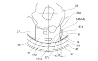
該ポール41の半径方向の外側の面(ラチェット21の内歯23と対向する面)には外歯41aが形成されており、該外歯41aの表面は、ブラスト処理により粗くされて、粗面化外歯41aとされている(図15(b)参照)。このため、強い衝撃力がシートバック3に加わったとき、ラチェット21を回転させようとする衝撃力がラチェット21の内歯23を介して粗面化外歯41aに伝わって粗面化外歯41aの各歯の各噛合壁面を押してポール41を半径方向内方へ移動させようとした場合でも、内歯23−粗面化外歯41a間の摩擦抵抗が高く、ラチェット23の回転が妨げられて、ポール41は現位置に留まろうとする。結果、粗面化外歯41aと内歯23の当接関係が維持され、ロック強度が保たれる。
また、粗面化外歯41aが形成された面と反対側の面(半径方向内側の面)には、カム31の第1突部31dが当接可能な第1内側壁41bと、カム31の第2突部31eが当接可能な第2内側壁41cとが形成されている。なお、本実施形態では、ロック状態に於いて、カム31の第1突部31dとポール41の第1内側壁41bは当接しているが、カム31の第2突部31eとポール41の第2内側壁41cは離間しており、ポール41が傾いた時に当接する。これら第1内側壁41b及び第2内側壁41cの表面もまた、外歯41aと同様に、ブラスト処理により粗くされて、第1粗面化内側壁41b、第2粗面化内側壁41cとされている(図15(c)参照)。このため、強い衝撃力がシートバック3に加わったとき、ラチェット21を回転させようとする衝撃力がラチェット21の内歯23を介して粗面化外歯41aに伝わって粗面化外歯41aの各歯の各噛合壁面を押してポール41を半径方向内方へ移動させようとし、これによりポール41に押されて、カム31の第1突部31dとポール41の第1粗面化内側壁41bの当接、及び、カム31の第2突部31eとポール41の第2粗面化内側壁41cの当接に滑りが発生しようとしたとしても、その滑りは、第1突部31d−第1粗面化内側壁41b間の摩擦抵抗、及び、第2突部31e−第2粗面化内側壁41c間の摩擦抵抗に妨げられる。このため、カム31はポール41を現位置に止めようとし、結果、粗面化外歯41aと内歯23との当接関係が維持され、ロック強度が保たれる。
Further, the first
ベースプレート25の円形凹部25aには、相対回転の軸Oを中心とする仮想円の周方向に沿って120°ピッチで3個のポールガイド突部37が形成されている。隣接する2個のポールガイド突部37間に位置するポール41、言い換えれば、隣接する2個のポールガイド突部37,37のガイド壁面37a,37bに挟まれたポール41は、当該のガイド壁面37a,37bの案内で、半径方向に沿って移動可能である。即ち、粗面化外歯41aがラチェット21の内歯23と噛合するロック位置と、粗面化外歯41aがラチェット21の内歯23と噛合しないアンロック位置との間で、ポール41は移動可能である。
In the
半径方向への移動時にポールガイド37のガイド壁面37a,37bに摺接して案内されるポール41の両側の側壁41p,41qは、ブラスト処理により粗くされて、粗面化側壁41p,41qとされて、摺動抵抗を高められている(図15(a)参照)。このため、強い衝撃力がシートバック3に加わったとき、ラチェット21を回転させようとする衝撃力がラチェット21の内歯23を介して粗面化外歯41aに伝わって粗面化外歯41aの各歯の各噛合壁面を押してポール41を半径方向内方へ移動させようとした場合でも、ポール41は上記の摺動抵抗により移動を妨げられて現位置に留まろうとする。これにより、粗面化外歯41aと内歯23との当接関係が維持され、ロック強度が保たれる。
The
各ポール41のレリーズプレート33と対向する面には、それぞれ、レリーズプレート33の方向へ突出する突部41dが形成されており、レリーズプレート33には、各ポール41の突部41dが係合する3個のカム孔33bが形成されている。このカム孔33bにはポール41の突部41dが当接する傾斜面が形成されており、レリーズプレート33が図1や図2内に示す矢印T方向と逆の方向へ回転するとき、突部41dは傾斜面により押される。その結果、ポール41は、ポールガイド37のガイド壁面37a,37bに摺接して案内されつつ、半径方向内方へ移動する。即ち、粗面化外歯41aがラチェット21の内歯23から離れるアンロック方向へ移動する。換言すれば、レリーズプレート33のカム孔33bの傾斜面は、そのような移動を生起させる形状に設定されている。
A
レリーズプレート33とラチェット21の円形凹部21aとの間には、略C状に湾曲された3本の線細工バネ51が配置される。ここで、本実施の形態のリクライニング装置4に於いて、ポール41をアンロック位置に保持するロック解除保持機構を説明する。
Three wirework springs 51 curved in a substantially C shape are arranged between the
図1に示すように、ラチェット(第1部材)21の内歯23より底面寄りの内筒面には、相対回転の軸Oに向かって突出し、円周方向に沿って延びる円弧状のガイド61が形成されている。このガイド61は、相対回転の軸Oに向かっての突出量(半径方向内方への突出量)が異なる2種類の円弧状突部から成る。第1の円弧状突部61aは、中心角がリクライニング装置のロック解除保持状態の角度に対応する角度に設定されている3個の小径部(軸芯から円弧状突部の突出先端までの半径距離が相対的に小さい部位)から成る。第2の円弧状突部61bは、これら3個の小径部の間に設けられており、半径方向内方への突出量が小径部より小さい3個の大径部から成る。
As shown in FIG. 1, an arc-shaped
図2に示すように、ポール41には、ラチェット21の円弧状のガイド61(第1の円弧状突部61a,第2の円弧状突部61b)の突出側の先端部位に当接可能な突部41eが形成されている。
第2の円弧状突部61bの突出量は、ポール41の突部41eが当該の第2の円弧状突部61bに対向する状態で、ポール41の粗面化外歯41aがラチェット21の内歯23に噛合可能な突出量に設定されている。一方、第1の円弧状突部61aの突出量は、ポール41の突部41eが当該の第1の円弧状突部61aに対向する状態で、ポール41の粗面化外歯41aがラチェット21の内歯23に噛合不可能な突出量に設定されている。
As shown in FIG. 2, the
The protrusion amount of the second
このように設定されているため、回転に伴いポール41の突部41eが、ラチェット21の第1の円弧状突部の突出先端側に乗り上げると、ポール41は内方へ移動する。これにより、粗面化外歯41aは、内歯23から離脱して、アンロック状態となる。このアンロック状態は、ポール41の突部41eが、ラチェット21の第1の円弧状突部の突出先端側に乗り上げている間、継続される。即ち、ロック解除保持機構としての機能が実現される。
Since it is set in this way, when the
次に、バネ51等により、ポール41とポールガイド37とのガタを防止する機構を、図1、図3〜4、図6を参照して説明する。
ポール41を挟むように設けられた隣接する2つのポールガイド37は、それぞれ、ポール41の一方の側壁(粗面化内側壁41p)と対向する第1のガイド壁面37aと、ポール41の他方の側壁(粗面化内側壁41q)と対向する第2のガイド壁面37bを有する。なお、ここでは、ポール41に着目して、その両側のポールガイド37について述べているが、ポールガイド37に着目した場合には、見る方向を図1、図3〜4、図6と同じ方向とした場合に於いて、当該のポールガイド37の右側の側壁が第2のガイド壁面37bとなり、左側の側壁が第1のガイド壁面37aとなる。また、下記の空間Sは、第1のガイド壁面37aをその一部として構成する側壁37cに設けた切欠き37dによって構成されることとなる。
Next, a mechanism for preventing backlash between the
The two adjacent pole guides 37 provided so as to sandwich the
空間Sは、ポール41の粗面化側壁41pの壁面と、ポールガイド37の側壁37cの切欠き37dの壁面との距離が、半径方向内方へ向かって徐々に減少する楔状の空間とされている。
略C字状を成す3本の線細工バネ51の一方の端部側には、ベースプレート25側に折曲された端部51aが形成され、他方の端部側には、ベースプレート25側に折曲された端部51bが形成されている。各線細工バネ51は、C字を外方へ拡げるように弾性変形された状態で、その一方の側の端部51aは、レリーズプレート33の軸孔33eの突出孔33gを通り、カム31に形成された係合孔31fに係合されている。また、他方の側の端部51bは、楔状の空間Sに挿入されている。このため、バネ51は、図6に示すように、内方へ戻ろうとする力で、係合孔31fの内壁面、及び、空間Sの形成壁を付勢する。つまり、力Fでカム31を付勢し、力F‘の分力でポール41の粗面化側壁41p及びポールガイド37の切欠き37dの内側を付勢する。
これにより、ポール41とポールガイド37とのガタが防止されている。
The space S is a wedge-shaped space in which the distance between the wall surface of the roughened
An
As a result, backlash between the
また、カム31が上記のように力Fで付勢される結果、カム31は、その第1突部31dが第1の粗面化内側壁41bに当接して付勢し、第2突部31eが第2の粗面化内側壁に当接して付勢する。これにより、ポール41は半径方向外方へ移動し、粗面化外歯41aが内歯23に噛合してロック状態となり、その状態を維持する。
Further, as a result of the
また、楔状の空間Sに挿入された端部51bは、ポール41の粗面化側壁41pを力F'で直接押 圧する。F'の分力F1'は、ポール41とポールガイド37とのガタをなくす方向にポール41を押圧している。また、F'の分力F2'は、線細工バネ51の端部51bをポール41のアンロック位置方向であるくさび状の空間Sに食い込む方向に付勢している。こうして、ガタが防止されるとともに、端部51bは、空間Sの狭まる方向へしっかりと嵌まり込む。
Further, the
本実施の形態のリクライニング装置4では、レリーズプレート33の周縁には、3個の凸部33hと3個の凹部33iとが、交互に形成されている。これら3個の凸部33h及び3個の凹部33iは、ポール41の粗面化外歯41aがラチェット21の内歯23aに噛合するロック状態では、線細工バネ51の端部51bとレリーズプレート33の凹部33iとが対向するように設定されている。
このため、アンロックする方向への回転に伴い、端部51bは凸部33hに乗り上げて、半径方向外方へ移動される。言い換えれば、空間Sの拡がる方向へ移動される。このため、ポール41を押す力は弱まり、ポール41の移動(アンロック方向への移動)はスムーズになる。
In the reclining device 4 of the present embodiment, three
Therefore, with the rotation in the unlocking direction, the
上記構成のリクライニング装置4の作動を説明する。
通常、線細工バネ51の弾性反発力により、カム31を介して、ベースプレート25に設けられたポール41は、粗面化外歯41aが、ラチェット21の内歯23に噛合したロック位置にあり、ラチェット(第1部材)21とベースプレート(第2部材)25との相対回転は妨げられる。即ち、シートバック3はシートクッション2に対して回転ができない状態(ロック状態)にある。
The operation of the reclining device 4 having the above configuration will be described.
Normally, due to the elastic rebound force of the
線細工バネ51の付勢力に抗して、カム31を操作して、他方の方向(矢印Tと逆の方向)に回転させると、カム31の突部31cとレリーズプレート33の係合孔33aの係合関係から、レリーズプレート33も共に回転する。最初に、線細工バネ51の端部51bと対向するレリーズプレート33の周縁が凹部33iから凸部33hに移行する。楔状の空間Sに食い込む方向に付勢されている線細工バネ51の端部51bは、レリーズプレート33の凸部33hにより、楔状の空間Sに食い込む方向と逆方向に引き抜かれ、線細工バネ51によるポール41の粗面化側壁41pbの押圧が弱くなる。
When the
さらに、レリーズプレート33が回転すると、ポール41の突部41dが係合するレリーズプレート33のカム孔33bの傾斜面により、ポール41は、粗面化外歯41aとラチェット21の内歯23との噛合が解除されたアンロック位置に移動し、ラチェット(第1部材)21とベースプレート (第2部材)25との相対回転が可能となる。即ち、シートバック3は、シートクッション2に対して回転可能となる。
Further, when the
カム31への操作力を解除すると、線細工バネ51の付勢力により、カム31、レリーズプレート33は元位置に復帰し、線細工バネ51の端部51bと対向するレリーズプレート33の周縁が凸部33hから凹部33iに移行し、ポール41の粗面化外歯41aがラチェット21の内歯23に噛合し、ラチェット(第1部材)21とベースプレート(第2部材)25との相対回転は妨げられる。即ち、再びロック状態となる。
When the operating force on the
本実施の形態のリクライニング装置4によれば、以下のような効果が得られる。
(1)ポール41の粗面化側壁部41pとガイド壁面37aとの間の位置に、ポール41が案内される方向に沿って漸次減少する楔状の空間Sを設け、線細工バネ51の端部51bを挿入している。このため、端部51bが、ポール41を力F'で押圧する。この力F'、ポール41とポールガイド37とのガタをなくすように作用する。よって、シートバックのガタを防止でき、従来必要であったポールをポールガイドに押しつける別の部材が不要となる。
(2) レリーズプレート33は、ポール41をアンロック位置方向へ移動させる前に、線細工バ ネ51の端部51bを楔状の空間Sに食い込む方向と逆の方向に引き抜く。これにより、線細工ばね51によるポール壁部41fへの押圧が弱くなり、ポール41は、スムーズにアンロック位置の方向へ移動できるようになる。
(3)ポールガイド37の側であるガイド壁面37aの部位に、相対回転の軸Oに向かうに従って相対回転の軸Oを中心とする円の周方向の幅が漸次狭くなる切欠き37dを設けている。このため、ポール41には切欠きを形成する必要がなく、ポール41の強度低下を防止できる。
According to the reclining device 4 of the present embodiment, the following effects can be obtained.
(1) A wedge-shaped space S that gradually decreases along the direction in which the
(2) Before moving the
(3) A
本発明は、上記実施の形態に限定するものではない。
例えば、楔状の空間Sは、図8〜図14に示すような形態でもよい。
なお、図8〜図14において、図1〜図7に示す部分と同じ部分は同一符号を付し、重複する説明は省略する。
The present invention is not limited to the above embodiment.
For example, the wedge-shaped space S may have a form as shown in FIGS. 8 to 14.
In FIGS. 8 to 14, the same parts as those shown in FIGS. 1 to 7 are designated by the same reference numerals, and redundant description will be omitted.
先ず、図8〜図10は、実施の形態と同様に、相対回転の軸Oに向かうに従って相対回転の軸Oを中心とする円の周方向の幅が漸次狭くなるくさび状の空間Sの他の形態例である。
図8では、ポール41にポールガイド壁部37c、粗面化側壁41p対して傾斜した底面を有した切欠き141aを設け、ガイド壁面37aの部位に、ポールガイド壁部37c、粗面化側壁41pに対して平行な切欠き137aを設けた。
First, FIGS. 8 to 10 show a wedge-shaped space S in which the width in the circumferential direction of the circle centered on the relative rotation axis O gradually narrows toward the relative rotation axis O, as in the embodiment. It is a morphological example of.
In FIG. 8, the
図9では、ポール41と、ガイド壁面37aの部位とに、ポールガイド壁部37c、粗面化側壁41pに対して傾斜した底面を有した切欠き241a、237aを設けた。
切欠き241a、237aの底面の傾斜は、いずれも、相対回転の軸Oに向かうに従って切欠きの深さが浅くなる斜面である。
In FIG. 9,
The slopes of the bottom surfaces of the
図10では、ポール41と、ガイド壁面37aとに、ポールガイド壁部37c、粗面化側壁41pに対して傾斜した底面を有した切欠き341a、337aを設けた。切欠き337aの底面の傾斜は、相対回転の軸Oに向かうに従って切欠きの深さが浅くなる斜面である。また、切欠き341aの底面の傾斜は、相対回転の軸Oに向かうに従って切欠きの深さが深くなる斜面である。
In FIG. 10, the
次に、図11〜図14は、実施の形態と異なり、相対回転の軸Oに向かうに従って相対回転の軸Oを中心とする円の周方向の幅が漸次広くなる楔状の空間S'の形態例である。
図11では、ガイド壁面37aの部位にのみポールガイド壁部37c、粗面化側壁41pに対して傾斜した底面を有した切欠き437aを設けた。
Next, unlike the embodiment, FIGS. 11 to 14 show a form of a wedge-shaped space S'in which the width in the circumferential direction of the circle centered on the relative rotation axis O gradually widens toward the relative rotation axis O. This is an example.
In FIG. 11, a
図12では、ポール41にポールガイド壁部37c、粗面化側壁41pに対して傾斜した底面を有した切欠き541aを設け、ガイド壁面37aの部位にポールガイド壁部37c、粗面化側壁41pに対して平行な切欠き537aを設けた。
図13では、ポール41と、ガイド壁面37aの部位とに、ポールガイド壁部37c、粗面化側壁41pに対して傾斜した底面を有した切欠き641a、637aを設けた。
In FIG. 12, the
In FIG. 13,
切欠き641a、637aの底面の傾斜は、いずれも、相対回転の軸Oに向かうに従って切欠きの深さが深くなる斜面である。又、切欠き641aの相対回転軸の軸Oと離れる方向の端部は、ポール41の粗面化内側壁41cと周方向でラップしている。
図14では、ポール41と、ガイド壁面37aの部位とに、ポールガイド壁部37c、粗面化側壁41pに対して傾斜した底面を有した切欠き741a、737aを設けた。
The inclination of the bottom surface of the
In FIG. 14,
切欠き737aの底面の傾斜は、相対回転の軸Oに向かうに従って切欠きの深さが深くなる斜面である。また、切欠き741aの底面の傾斜は、相対回転の軸Oに向かうに従って切欠きの深さが浅くなる斜面である。
さらに、上記実施の形態では、線細工バネ51の端部51aは、カム31に係合し、カム31を付勢したが、カム31と一体となって回転するレリーズプレート33に係合させてもよい。
The inclination of the bottom surface of the
Further, in the above embodiment, the
次に、粗面化処理について説明する。
前記では、ポール41の外歯41a、側壁41p,41q、内側壁41b,41cを、ブラスト処理によって粗面化して摩擦抵抗や摺動抵抗を増加させているが、粗面化処理としては、ブラスト処理に限らず、例えば、薬品を用いて対象表面を粗面化してもよい。また、プレスによって対象の表面を粗面化してもよい。また、ポールの他の面に粗面化処理をしてもよい。また、側壁41p,41qのどちらか一方にだけ粗面化処理をしてもよい。内側壁41b,41cに関しても同様であり、どちらか一方にだけ粗面化処理をしてもよい。
Next, the roughening process will be described.
In the above, the
プレスの場合、対象表面を粗面化するための別途のプレス(ポール41を成形するためのプレスとは別の対象表面を粗面化するためのみのプレス)でもよいが、ポール41を成形する際に、同時に対象表面を粗面化するプレスであってもよい。そのためには、例えば、金型表面に粗面化するための微細な凹凸を形成しておく等の手法が考えられる。
In the case of a press, a separate press for roughening the target surface (a press for roughening the target surface different from the press for molding the pole 41) may be used, but the
また、前記で言及したブラスト処理としては、所望の粗面化を対象表面に行うことができる公知の処理を採用することできる。粒子サイズとしては、例えば、外歯41aを粗面化する場合であれば、外歯41aの歯サイズよりも十分に小さく、外歯の歯としての機能を損なわないサイズであることが必要となる。
Further, as the blasting treatment mentioned above, a known treatment capable of performing a desired roughening on the target surface can be adopted. The particle size, for example, when roughening the
21 ラチェット(第1部材)
25 ベースプレート(第2部材)
31 カム
37 ポールガイド
37a ガイド壁面(第1のガイド壁面)
37b ガイド壁面(第2のガイド壁面)
37c 壁部(一方の壁部)
S 空間(一方の壁部37cの切欠きとして形成された、粗面化側壁41pとの間の空間)
41 ポール
41a 粗面化外歯
41b 粗面化内側壁
41c 粗面化内側壁
41p 粗面化側壁
41q 粗面化側壁
51 線細工ばね
21 Ratchet (1st member)
25 Base plate (second member)
31
37b Guide wall surface (second guide wall surface)
37c wall (one wall)
S space (space between the roughened
41
Claims (4)
前記内歯と噛合可能な外歯を有するポールと、
前記第1部材の開放面側に該第1部材と相対回転可能に同軸に設けられ、前記外歯が前記内歯に噛合して前記相対回転を妨げるロック位置と、前記外歯が前記内歯から離脱して前記相対回転を許容するアンロック位置との間で前記ポールの移動を案内するポールガイドを有する第2部材と、
前記第1部材と前記第2部材の間に両部材と同軸に相対回転可能に設けられ、回転角位置に応じて前記外歯が前記内歯と噛合する方向へ前記ポールを付勢するカムと、
を有するリクライニング装置であって、
前記ポールは、前記ポールガイドのガイド壁面に対向して案内される両側の側壁の少なくとも一方に、その壁面を粗面化処理された粗面化側壁を有し、さらに、前記外歯として、その表面を粗面化処理された粗面化外歯を有する、
ことを特徴とするリクライニング装置。 A first member having a bottomed cylindrical shape and having internal teeth on the inner peripheral surface along the circumferential direction.
A pole having external teeth that can mesh with the internal teeth,
A lock position is provided on the open surface side of the first member so as to be coaxial with the first member so that the external teeth mesh with the internal teeth to prevent the relative rotation, and the external teeth are the internal teeth. A second member having a pole guide that guides the movement of the pole to and from an unlocked position that allows relative rotation.
A cam that is provided between the first member and the second member so as to be coaxially rotatable relative to both members and urges the pole in a direction in which the outer teeth mesh with the inner teeth according to the rotation angle position. ,
It is a reclining device that has
The pawl, the sides at least one side wall of which is guided so as to face the pole guide of the guide wall, have a surface-roughened roughened sidewall its wall, further, as the outer teeth, that to have the roughening treated roughened outer tooth surface,
A reclining device characterized by that.
前記ポールは、さらに、前記カムからの付勢力を受ける内側壁として、その壁面を粗面化処理された粗面化内側壁を有する、
ことを特徴とするリクライニング装置。 In claim 1,
The pole further has a roughened inner wall surface whose wall surface has been roughened as an inner wall surface that receives the urging force from the cam .
A reclining device characterized by that.
前記内歯と噛合可能な外歯を有するポールと、
前記第1部材の開放面側に該第1部材と相対回転可能に同軸に設けられ、前記外歯が前記内歯に噛合して前記相対回転を妨げるロック位置と、前記外歯が前記内歯から離脱して前記相対回転を許容するアンロック位置との間で前記ポールの移動を案内するポールガイドを有する第2部材と、
前記第1部材と前記第2部材の間に両部材と同軸に相対回転可能に設けられ、回転角位置に応じて前記外歯が前記内歯と噛合する方向へ前記ポールを付勢するカムと、
を有するリクライニング装置の製造方法であって、
前記ポールガイドのガイド壁面に対向して案内される前記ポールの側壁の壁面に粗面化処理を施し、さらに、前記ポールの外歯に粗面化処理を施す、
ことを特徴とするリクライニング装置の製造方法。 A first member having a bottomed cylindrical shape and having internal teeth on the inner peripheral surface along the circumferential direction.
A pole having external teeth that can mesh with the internal teeth,
A lock position is provided on the open surface side of the first member so as to be coaxial with the first member so that the external teeth mesh with the internal teeth to prevent the relative rotation, and the external teeth are the internal teeth. A second member having a pole guide that guides the movement of the pole to and from an unlocked position that allows relative rotation.
A cam that is provided between the first member and the second member so as to be coaxially rotatable relative to both members and urges the pole in a direction in which the outer teeth mesh with the inner teeth according to the rotation angle position. ,
It is a manufacturing method of a reclining device having
And facilities the roughening treatment on the wall surface of the side wall of the pole to be guided to face the guide wall surface of the pawl guide, further to facilities roughened the external teeth of the pole,
A method of manufacturing a reclining device, which is characterized in that.
前記ポールが前記カムにより付勢される側壁である内側壁の壁面に粗面化処理を施す、
ことを特徴とするリクライニング装置の製造方法。
In claim 3, further
The wall surface of the inner side wall, which is the side wall on which the pole is urged by the cam, is roughened .
A method of manufacturing a reclining device, which is characterized in that.
Priority Applications (2)
| Application Number | Priority Date | Filing Date | Title |
|---|---|---|---|
| JP2016148085A JP6756535B2 (en) | 2016-07-28 | 2016-07-28 | Reclining device and manufacturing method of reclining device |
| US15/655,709 US10414295B2 (en) | 2016-07-28 | 2017-07-20 | Reclining device and method of manufacturing reclining device |
Applications Claiming Priority (1)
| Application Number | Priority Date | Filing Date | Title |
|---|---|---|---|
| JP2016148085A JP6756535B2 (en) | 2016-07-28 | 2016-07-28 | Reclining device and manufacturing method of reclining device |
Publications (2)
| Publication Number | Publication Date |
|---|---|
| JP2018015268A JP2018015268A (en) | 2018-02-01 |
| JP6756535B2 true JP6756535B2 (en) | 2020-09-16 |
Family
ID=61012440
Family Applications (1)
| Application Number | Title | Priority Date | Filing Date |
|---|---|---|---|
| JP2016148085A Active JP6756535B2 (en) | 2016-07-28 | 2016-07-28 | Reclining device and manufacturing method of reclining device |
Country Status (2)
| Country | Link |
|---|---|
| US (1) | US10414295B2 (en) |
| JP (1) | JP6756535B2 (en) |
Families Citing this family (6)
| Publication number | Priority date | Publication date | Assignee | Title |
|---|---|---|---|---|
| JP6760329B2 (en) * | 2018-05-09 | 2020-09-23 | トヨタ紡織株式会社 | Vehicle seat reclining device |
| US10610018B1 (en) * | 2018-11-13 | 2020-04-07 | Lear Corporation | Dual cam recliner mechanism |
| CN109318767B (en) * | 2018-12-07 | 2021-02-23 | 黄春光 | Automobile safety seat |
| DE102019104712A1 (en) | 2019-02-25 | 2020-08-27 | Brose Fahrzeugteile SE & Co. Kommanditgesellschaft, Coburg | Locking fitting for a vehicle seat |
| JP7434842B2 (en) | 2019-11-28 | 2024-02-21 | トヨタ紡織株式会社 | Vehicle seat reclining device |
| DE102020105874B3 (en) * | 2020-03-04 | 2021-05-06 | Thomas Birmanns | BRAKE DEVICE |
Family Cites Families (13)
| Publication number | Priority date | Publication date | Assignee | Title |
|---|---|---|---|---|
| US5154476A (en) * | 1991-02-21 | 1992-10-13 | Hoover Universal, Inc. | Locking seat recliner |
| JP4716097B2 (en) * | 2005-07-27 | 2011-07-06 | アイシン精機株式会社 | Locking device and seat reclining device |
| US7588294B2 (en) * | 2006-11-28 | 2009-09-15 | Fuji Kiko Co., Ltd. | Seat reclining device for vehicle |
| KR101342224B1 (en) * | 2007-01-17 | 2013-12-16 | 인티어 오토모티브, 인크. | Disc recliner assembly with biased synchronization |
| JP5051165B2 (en) * | 2008-07-15 | 2012-10-17 | アイシン精機株式会社 | Vehicle seat reclining device |
| KR100907370B1 (en) * | 2009-03-16 | 2009-07-10 | 대원정밀공업(주) | Recliner for Car Seat |
| JP5644288B2 (en) * | 2010-09-07 | 2014-12-24 | 株式会社今仙電機製作所 | Reclining device |
| JP5821654B2 (en) * | 2011-02-24 | 2015-11-24 | アイシン精機株式会社 | Vehicle seat reclining device |
| JP5638994B2 (en) | 2011-03-28 | 2014-12-10 | シロキ工業株式会社 | Reclining device |
| JP6018859B2 (en) * | 2012-09-19 | 2016-11-02 | シロキ工業株式会社 | Reclining device |
| US9623774B2 (en) * | 2013-03-22 | 2017-04-18 | Aisin Seiki Kabushiki Kaisha | Seat reclining device for vehicles |
| KR101427567B1 (en) * | 2013-07-02 | 2014-08-07 | (주)케이엠앤아이 | Recliner for Motor Vehicle having Wedge |
| JP6191313B2 (en) * | 2013-08-01 | 2017-09-06 | トヨタ紡織株式会社 | Recliner |
-
2016
- 2016-07-28 JP JP2016148085A patent/JP6756535B2/en active Active
-
2017
- 2017-07-20 US US15/655,709 patent/US10414295B2/en active Active
Also Published As
| Publication number | Publication date |
|---|---|
| US10414295B2 (en) | 2019-09-17 |
| US20180029506A1 (en) | 2018-02-01 |
| JP2018015268A (en) | 2018-02-01 |
Similar Documents
| Publication | Publication Date | Title |
|---|---|---|
| JP6756535B2 (en) | Reclining device and manufacturing method of reclining device | |
| JP6491978B2 (en) | Reclining device | |
| JP7114298B2 (en) | reclining device | |
| US7604296B2 (en) | Vehicle seat reclining apparatus | |
| US8602498B2 (en) | Seat reclining apparatus | |
| US8651578B2 (en) | Seat reclining apparatus for vehicle | |
| US9701222B2 (en) | Vehicle seat and method for manufacturing the same | |
| JP5668702B2 (en) | Vehicle seat reclining device | |
| JP2002065387A (en) | Device of reclining seatback for vehicle | |
| JP2004249091A (en) | Round recliner for vehicle | |
| JP2007135797A (en) | Seat reclining device for vehicle | |
| JP5281857B2 (en) | Reclining device | |
| EP1433652B1 (en) | Recliner adjuster for a seat | |
| US11772527B2 (en) | Seat reclining device for vehicle | |
| JP6756536B2 (en) | Reclining device and manufacturing method of reclining device | |
| JP6385541B2 (en) | Reclining device | |
| JP2002101993A (en) | Reclining structure of seat | |
| JP6788481B2 (en) | Reclining device | |
| JP6745201B2 (en) | Reclining device | |
| WO2021107138A1 (en) | Vehicle seat reclining device | |
| JP5043367B2 (en) | Reclining device | |
| JP4503273B2 (en) | Seat reclining adjuster | |
| JP7259723B2 (en) | Vehicle seat reclining device | |
| JP2019041962A (en) | Reclining device | |
| CN113710126B (en) | Seat reclining device for vehicle |
Legal Events
| Date | Code | Title | Description |
|---|---|---|---|
| A621 | Written request for application examination |
Free format text: JAPANESE INTERMEDIATE CODE: A621 Effective date: 20190605 |
|
| A977 | Report on retrieval |
Free format text: JAPANESE INTERMEDIATE CODE: A971007 Effective date: 20200601 |
|
| A131 | Notification of reasons for refusal |
Free format text: JAPANESE INTERMEDIATE CODE: A131 Effective date: 20200609 |
|
| A521 | Request for written amendment filed |
Free format text: JAPANESE INTERMEDIATE CODE: A523 Effective date: 20200730 |
|
| TRDD | Decision of grant or rejection written | ||
| A01 | Written decision to grant a patent or to grant a registration (utility model) |
Free format text: JAPANESE INTERMEDIATE CODE: A01 Effective date: 20200811 |
|
| A61 | First payment of annual fees (during grant procedure) |
Free format text: JAPANESE INTERMEDIATE CODE: A61 Effective date: 20200827 |
|
| R150 | Certificate of patent or registration of utility model |
Ref document number: 6756535 Country of ref document: JP Free format text: JAPANESE INTERMEDIATE CODE: R150 |
|
| S111 | Request for change of ownership or part of ownership |
Free format text: JAPANESE INTERMEDIATE CODE: R313113 |
|
| R350 | Written notification of registration of transfer |
Free format text: JAPANESE INTERMEDIATE CODE: R350 |
|
| R250 | Receipt of annual fees |
Free format text: JAPANESE INTERMEDIATE CODE: R250 |
|
| R250 | Receipt of annual fees |
Free format text: JAPANESE INTERMEDIATE CODE: R250 |