JP6748846B2 - Component mounting system, data feedback method in component mounting system, and program for executing data feedback method in component mounting system - Google Patents
Component mounting system, data feedback method in component mounting system, and program for executing data feedback method in component mounting system Download PDFInfo
- Publication number
- JP6748846B2 JP6748846B2 JP2016168681A JP2016168681A JP6748846B2 JP 6748846 B2 JP6748846 B2 JP 6748846B2 JP 2016168681 A JP2016168681 A JP 2016168681A JP 2016168681 A JP2016168681 A JP 2016168681A JP 6748846 B2 JP6748846 B2 JP 6748846B2
- Authority
- JP
- Japan
- Prior art keywords
- component
- mounting
- lead
- post
- estimated
- Prior art date
- Legal status (The legal status is an assumption and is not a legal conclusion. Google has not performed a legal analysis and makes no representation as to the accuracy of the status listed.)
- Active
Links
Images


Landscapes
- Supply And Installment Of Electrical Components (AREA)
Description
本発明は、リード付きの部品を基板に装着する部品実装装置と部品実装装置により基板に装着された部品の装着状態を検査する検査装置を備えた部品実装システム及びこの部品実装システムにおけるデータフィードバック方法並びに部品実装システムにおけるデータフィードバック方法を実行するためのプログラムに関するものである。 The present invention relates to a component mounting system including a component mounting apparatus for mounting a component with leads on a board and an inspection apparatus for inspecting a mounting state of a component mounted on the board by the component mounting apparatus, and a data feedback method in the component mounting system. And a program for executing the data feedback method in the component mounting system .
従来、基板に部品を装着する部品実装装置と、部品実装装置により基板に装着された部品の装着状態を検査する検査装置とを備えた部品実装システムが知られている。このような部品実装システムでは、検査装置における部品の装着状態の検査の際に、基板に対する部品の位置を把握し、これを部品実装装置にフィードバックすることによって、部品実装装置における部品の装着精度を向上させることができる(例えば、下記の特許文献1)。
2. Description of the Related Art Conventionally, a component mounting system including a component mounting apparatus that mounts a component on a board and an inspection apparatus that inspects a mounting state of the component mounted on the board by the component mounting apparatus is known. In such a component mounting system, at the time of inspecting the mounting state of the component in the inspection device, the position of the component with respect to the board is grasped and fed back to the component mounting device to check the mounting precision of the component in the component mounting device. It can be improved (for example,
例えば、部品がリード付きの部品である場合、検査装置は、基板に装着された部品を上方から撮像して得られる画像から部品のボディの外形を求めてボディの位置を算出し、その算出したボディの位置が予め設定された領域内に収まっているかどうか等に基づいてその部品の装着状態を検査するとともに、リードの外形を求めてリードの位置を算出し、その算出したリードの位置のデータを部品実装装置にフィードバックする。部品実装装置は、そのフィードバックされたリードの位置のデータに基づいて、制御データ上での部品の装着位置と実際の部品の装着位置との差を求め、その差に基づいて、部品装着時における部品の位置補正を行う。これにより部品実装装置による部品の装着精度を高めることができる。 For example, when the component is a leaded component, the inspection apparatus calculates the position of the body by obtaining the outer shape of the body of the component from the image obtained by imaging the component mounted on the board from above. The mounting state of the component is inspected based on whether the body position is within the preset area, etc., and the lead position is calculated by obtaining the lead outer shape, and the calculated lead position data Is fed back to the component mounting apparatus. The component mounting apparatus obtains the difference between the component mounting position on the control data and the actual component mounting position based on the fed back lead position data, and based on the difference, the component mounting time Correct the position of parts. As a result, the mounting accuracy of the component by the component mounting apparatus can be improved.
しかしながら、基板に装着されたリード付きの部品のリードの全部又は一部がランドに塗布された半田に埋もれた状態となっている場合には、検査装置はリードの外形の全体を把握できない状態でリードの位置を算出することになる。このため、検査装置において算出されるリードの位置の信頼性は低くなり、このような信頼性の低いデータを部品実装装置にフィードバックすることは、部品実装装置における部品の装着精度を却って低下させるおそれがある。 However, if all or part of the leads of the leaded component mounted on the board are buried in the solder applied to the land, the inspection device cannot grasp the entire outline of the lead. The position of the lead will be calculated. Therefore, the reliability of the position of the lead calculated by the inspection device becomes low, and feeding back such low-reliability data to the component mounting device may rather reduce the mounting accuracy of the component in the component mounting device. There is.
そこで本発明は、信頼性の高いデータのみが部品実装装置にフィードバックされるようにして部品の装着精度を高めることができる部品実装システム及び部品実装システムにおけるデータフィードバック方法並びに部品実装システムにおけるデータフィードバック方法を実行するためのプログラムを提供することを目的とする。 Therefore, the present invention provides a component mounting system, a data feedback method in the component mounting system, and a data feedback method in the component mounting system, in which only highly reliable data is fed back to the component mounting apparatus to improve the component mounting accuracy. The purpose is to provide a program for executing .
本発明の部品実装システムは、リード付の部品を基板に装着する部品実装装置と、前記部品実装装置により前記基板に装着された前記部品の装着状態を検査する検査装置とを備えた部品実装システムであって、前記部品実装装置に備えられ、前記基板に装着する前の前記部品を撮像する第1のカメラと、前記第1のカメラにより前記部品を撮像して得られる画像に基づいて前記部品のボディとリードの相対位置関係を算出する相対位置関係算出部と、前記検査装置に備えられ、前記部品実装装置により前記基板に装着された前記部品を撮像する第2のカメラと、前記第2のカメラにより前記部品を撮像して得られる画像に基づいて前記基板に対する前記部品の前記ボディの位置である装着後ボディ位置及び前記部品の前記リードの重心位置である装着後リード位置を算出する装着後位置算出部と、前記相対位置関係算出部が算出した前記相対位置関係と前記装着後位置算出部が算出した前記装着後ボディ位置とに基づいて、前記基板に装着された前記部品の前記リードの重心の推定位置である推定リード位置を算出する推定リード位置算出部と、前記装着後リード位置と前記推定リード位置とを比較し、前記装着後リード位置と前記推定リード位置との間の誤差を算出する誤差算出部と、前記誤差算出部が算出した前記誤差が所定の閾値以下であるかどうかを判断する判断部と、前記判断部において前記誤差が前記閾値以下であると判断された場合に、前記装着後リード位置のデータを前記部品実装装置にフィードバックするフィードバック制御部とを備えた。
また、本発明の部品実装システムは、リード付の部品を基板に装着する部品実装装置と、前記部品実装装置により前記基板に装着された前記部品を撮像するカメラと、前記カメラにより前記部品を撮像して得られる画像に基づいて前記基板に対する前記部品の前記ボディの位置である装着後ボディ位置及び前記部品の前記リードの重心位置である装着後リード位置を算出する装着後位置算出部と、予め算出した基板に装着する前の前記部品のボディとリードの相対位置関係と、前記装着後位置算出部が算出した前記装着後ボディ位置とに基づいて、前記基板に装着された前記部品の前記リードの重心の推定位置である推定リード位置を算出する推定リード位置算出部と、前記装着後リード位置と前記推定リード位置とを比較し、前記装着後リード位置と前記推定リード位置との間の誤差を算出する誤差算出部と、前記誤差算出部が算出した前記誤差が所定の閾値以下であるかどうかを判断する判断部と、前記判断部において前記誤差が前記閾値以下であると判断された場合に、前記装着後リード位置のデータを前記部品実装装置にフィードバックするフィードバック制御部とを備えた。
A component mounting system according to the present invention includes a component mounting device that mounts a component with leads on a substrate, and an inspection device that inspects a mounting state of the component mounted on the substrate by the component mounting device. A first camera provided in the component mounting apparatus for capturing an image of the component before being mounted on the board; and the component based on an image obtained by capturing the image of the component by the first camera. A relative positional relationship calculation unit that calculates a relative positional relationship between the body and the lead, a second camera that is provided in the inspection apparatus, and that captures an image of the component mounted on the board by the component mounting apparatus; Mounting based on an image obtained by capturing an image of the component by the camera, the post-mounting body position that is the position of the body of the component with respect to the substrate and the post-mounting lead position that is the center of gravity of the lead of the component. A rear position calculation unit, the lead of the component mounted on the board based on the relative positional relationship calculated by the relative positional relationship calculation unit and the post-mounting body position calculated by the post-mounting position calculation unit. An estimated lead position calculation unit that calculates an estimated lead position that is an estimated position of the center of gravity of the robot, compares the post-mounting lead position and the estimated lead position, and determines an error between the post-mounting lead position and the estimated lead position. An error calculation unit that calculates the error, a determination unit that determines whether the error calculated by the error calculation unit is less than or equal to a predetermined threshold, and the determination unit determines that the error is less than or equal to the threshold. And a feedback control unit for feeding back the data of the lead position after mounting to the component mounting apparatus.
Further, the component mounting system of the present invention includes a component mounting device that mounts a component with leads on a substrate, a camera that images the component mounted on the substrate by the component mounting device, and an image of the component that is captured by the camera. A post-mounting position calculation unit that calculates a post-mounting body position that is the position of the body of the component with respect to the substrate and a post-mounting lead position that is the center of gravity of the leads of the component based on the image obtained by The lead of the component mounted on the board is calculated based on the calculated relative positional relationship between the body and the lead of the component before mounting on the board and the post-mounting body position calculated by the post-mounting position calculation unit. An estimated lead position calculation unit that calculates an estimated lead position that is an estimated position of the center of gravity of the robot, compares the post-mounting lead position and the estimated lead position, and determines an error between the post-mounting lead position and the estimated lead position. An error calculation unit that calculates the error, a determination unit that determines whether the error calculated by the error calculation unit is less than or equal to a predetermined threshold, and the determination unit determines that the error is less than or equal to the threshold. And a feedback control unit for feeding back the data of the lead position after mounting to the component mounting apparatus.
本発明の部品実装システムにおけるデータフィードバック方法は、リード付きの部品を基板に装着する部品実装装置と、前記部品実装装置により前記基板に装着された前記部品の装着状態を検査する検査装置とを備えた部品実装システムにおけるデータフィードバック方法であって、前記部品実装装置に備えられた第1のカメラにより、前記基板に装着する前の前記部品を撮像する第1の撮像工程と、前記第1の撮像工程で前記部品を撮像して得られる画像に基づいて前記部品のボディとリードの相対位置関係を算出する相対位置関係算出工程と、前記検査装置に備えられた第2のカメラにより、前記部品実装装置により前記基板に装着された前記部品を撮像する第2の撮像工程と、前記第2の撮像工程で前記部品を撮像して得られる画像に基づいて前記基板に対する前記部品の前記ボディの位置である装着後ボディ位置及び前記部品の前記リードの重心位置である装着後リード位置を算出する装着後位置算出工程と、前記相対位置関係算出工程で算出した前記相対位置関係と前記装着後位置算出工程で算出した前記装着後ボディ位置とに基づいて、前記基板に装着された前記部品の前記リードの重心の推定位置である推定リード位置を算出する推定リード位置算出工程と、前記装着後リード位置と前記推定リード位置とを比較し、前記装着後リード位置と前記推定リード位置との間の誤差を算出する誤差算出工程と、前記誤差算出工程で算出した前記誤差が所定の閾値以下であるかどうかを判断する判断工程と、前記判断工程で前記誤差が前記閾値以下であると判断した場合に、前記装着後リード位置のデータを前記部品実装装置にフィードバックするフィードバック工程とを含む。
また、本発明の部品実装システムにおけるデータフィードバック方法は、リード付きの部品を基板に装着する部品実装装置を備えた部品実装システムにおけるデータフィードバック方法であって、前記部品実装装置により前記基板に装着された前記部品を撮像する撮像工程と、前記撮像工程で前記部品を撮像して得られる画像に基づいて前記基板に対する前記部品の前記ボディの位置である装着後ボディ位置及び前記部品の前記リードの重心位置である装着後リード位置を算出する装着後位置算出工程と、予め算出した基板に装着する前の前記部品のボディとリードの相対位置関係と、前記装着後位置算出工程で算出した前記装着後ボディ位置とに基づいて、前記基板に装着された前記部品の前記リードの重心の推定位置である推定リード位置を算出する推定リード位置算出工程と、前記装着後リード位置と前記推定リード位置とを比較し、前記装着後リード位置と前記推定リード位置との間の誤差を算出する誤差算出工程と、前記誤差算出工程で算出した前記誤差が所定の閾値以下であるかどうかを判断する判断工程と、前記判断工程で前記誤差が前記閾値以下であると判断した場合に、前記装着後リード位置のデータを前記部品実装装置にフィードバックするフィードバック工程とを含む。
また、本発明の部品実装システムにおけるデータフィードバック方法を実行するためのプログラムは、リード付きの部品を基板に装着する部品実装装置と、前記部品実装装置により前記基板に装着された前記部品の装着状態を検査する検査装置とを備えた部品実装システムにおけるデータフィードバック方法を実行するためのプログラムであって、前記部品実装装置に備えられた第1のカメラにより、前記基板に装着する前の前記部品を撮像するステップと、前記部品を撮像して得られる画像に基づいて前記部品のボディとリードの相対位置関係を算出するステップと、前記検査装置に備えられた第2のカメラにより、前記部品実装装置により前記基板に装着された前記部品を撮像するステップと、前記部品を撮像して得られる画像に基づいて前記基板に対する前記部品の前記ボディの位置である装着後ボディ位置及び前記部品の前記リードの重心位置である装着後リード位置を算出するステップと、算出した前記相対位置関係と前記装着後ボディ位置とに基づいて、前記基板に装着された前記部品の前記リードの重心の推定位置である推定リード位置を算出するステップと、前記装着後リード位置と前記推定リード位置とを比較し、前記装着後リード位置と前記推定リード位置との間の誤差を算出するステップと、算出した前記誤差が所定の閾値以下であるかどうかを判断するステップと、前記誤差が前記閾値以下であると判断した場合に、前記装着後リード位置のデータを前記部品実装装置にフィードバックするステップとを実行する。
また、本発明の部品実装システムにおけるデータフィードバック方法を実行するためのプログラムは、リード付きの部品を基板に装着する部品実装装置を備えた部品実装システムにおけるデータフィードバック方法を実行するためのプログラムであって、前記部品実装装置により前記基板に装着された前記部品を撮像するステップと、前記部品を撮像して得られる画像に基づいて前記基板に対する前記部品の前記ボディの位置である装着後ボディ位置及び前記部品の前記リードの重心位置である装着後リード位置を算出するステップと、予め算出した基板に装着する前の前記部品のボディとリードの相対位置関係と、算出した前記装着後ボディ位置とに基づいて、前記基板に装着された前記部品の前記リードの重心の推定位置である推定リード位置を算出するステップと、前記装着後リード位置と前記推定リード位置とを比較し、前記装着後リード位置と前記推定リード位置との間の誤差を算出するステップと、算出した前記誤差が所定の閾値以下であるかどうかを判断するステップと、前記誤差が前記閾値以下であると判断した場合に、前記装着後リード位置のデータを前記部品実装装置にフィードバックするステップとを実行する。
A data feedback method in a component mounting system of the present invention comprises a component mounting apparatus that mounts a component with leads on a board, and an inspection apparatus that inspects a mounting state of the component mounted on the board by the component mounting apparatus. A data feedback method in a component mounting system, comprising: a first image capturing step of capturing an image of the component before being mounted on the board by a first camera provided in the component mounting apparatus; A relative positional relationship calculating step of calculating a relative positional relationship between the body of the component and a lead based on an image obtained by imaging the component in the step, and mounting the component by a second camera provided in the inspection device. A second image pickup step of picking up an image of the component mounted on the board by an apparatus; and a position of the body of the part with respect to the board based on an image obtained by picking up an image of the part in the second image pickup step. A post-mounting position calculating step of calculating a certain post-mounting body position and a post-mounting lead position which is the center of gravity of the lead of the component, the relative positional relationship calculated in the relative positional relationship calculating step, and the post-mounting position calculating step An estimated lead position calculation step of calculating an estimated lead position that is an estimated position of the center of gravity of the leads of the component mounted on the board based on the post-mounting body position calculated in An error calculating step of comparing the estimated lead position and calculating an error between the post-mounting lead position and the estimated lead position, and whether the error calculated in the error calculating step is less than or equal to a predetermined threshold value. And a feedback step of feeding back the data of the post-mounting lead position to the component mounting apparatus when the error is less than or equal to the threshold value in the determining step.
A data feedback method in the component mounting system of the present invention is a data feedback method in a component mounting system including a component mounting apparatus for mounting a component with a lead on a board, wherein the component mounting apparatus mounts the component on the board. And a center of gravity of the lead of the component, which is a position of the body of the component with respect to the board, based on an image obtained by capturing the component in the imaging process. Post-mounting position calculation step of calculating the post-mounting lead position, which is the position, relative positional relationship between the body of the component and the lead before mounting on the board, which is calculated in advance, and the post-mounting position calculated in the post-mounting position calculation step. An estimated lead position calculating step of calculating an estimated lead position which is an estimated position of the center of gravity of the lead of the component mounted on the board, and a post-mounting lead position and the estimated lead position. An error calculating step of comparing and calculating an error between the post-mounting lead position and the estimated lead position, and a determining step of determining whether the error calculated in the error calculating step is less than or equal to a predetermined threshold value. And a feedback step of feeding back the data of the post-mounting lead position to the component mounting apparatus when the determination step determines that the error is equal to or less than the threshold value.
Further, the program for executing the data feedback method in the component mounting system of the present invention includes a component mounting apparatus that mounts a component with a lead on a board, and a mounting state of the component mounted on the board by the component mounting apparatus. A program for executing a data feedback method in a component mounting system including an inspection device for inspecting the component, wherein the first camera provided in the component mounting device detects the component before mounting on the board. The step of capturing the image, the step of calculating the relative positional relationship between the body of the component and the lead based on the image obtained by capturing the image of the component, and the component mounting apparatus by the second camera provided in the inspection device. The step of capturing an image of the component mounted on the board by means of: a post-attachment body position which is the position of the body of the component with respect to the board based on an image obtained by capturing the component, and the lead of the component. Estimating the position of the center of gravity of the lead of the component mounted on the board, based on the step of calculating the post-mounting lead position that is the position of the center of gravity, and the calculated relative positional relationship and the post-mounting body position. A step of calculating a lead position; a step of comparing the post-mounting lead position with the estimated lead position to calculate an error between the post-mounting lead position and the estimated lead position; And the step of feeding back the data of the post-mounting lead position to the component mounting apparatus when it is determined that the error is less than or equal to the threshold value.
Further, the program for executing the data feedback method in the component mounting system of the present invention is a program for executing the data feedback method in the component mounting system including the component mounting apparatus for mounting the component with leads on the board. An image of the component mounted on the board by the component mounting apparatus, and a post-mounting body position which is a position of the body of the component with respect to the board based on an image obtained by capturing the component, and The step of calculating a post-mounting lead position which is the center of gravity of the lead of the component, the relative positional relationship between the body of the component and the lead before being mounted on the board, which has been calculated in advance, and the calculated post-mounting body position. A step of calculating an estimated lead position, which is an estimated position of the center of gravity of the lead of the component mounted on the substrate, and comparing the post-mounting lead position and the estimated lead position, the post-mounting lead position And a step of calculating an error between the estimated lead position, a step of determining whether the calculated error is less than or equal to a predetermined threshold value, and when the error is determined to be less than or equal to the threshold value, And feeding back the data of the lead position after mounting to the component mounting apparatus.
本実施の形態における部品実装システムによれば、信頼性の高いデータのみが部品実装装置にフィードバックされるので、部品の装着精度を高めることができる。 According to the component mounting system of the present embodiment, only highly reliable data is fed back to the component mounting apparatus, so that the component mounting accuracy can be improved.
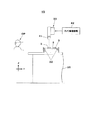
以下、図面を参照して本発明の実施の形態について説明する。図1は本発明の一実施の形態における部品実装システム1を示している。この部品実装システム1は部品実装装置1Aと検査装置1Bのほか、図示しないスクリーン印刷装置やリフロー装置等を備えて構成されている。部品実装装置1Aは、基板2にリード付きの部品3を装着する装置であり、検査装置1Bは、部品実装装置1Aから基板2を受け取ってその基板2における部品3の装着状態の検査を行う装置である。部品実装装置1Aと検査装置1B及び部品実装システム1を構成する他の装置(上述のスクリーン印刷装置等)とは、ホストコンピュータ1Cを通じて互いに情報のやり取りを行うことができる。
Hereinafter, embodiments of the present invention will be described with reference to the drawings. FIG. 1 shows a
本実施の形態では、説明の便宜上、作業者OPから見た部品実装システム1の左右方向をX軸方向とし、左方を上流工程側、右方を下流工程側とする。また、作業者OPから見た部品実装システム1の前後方向をY軸方向とし、作業者OPから見た手前側を前方、作業者OPから見た奥側を後方とする。更に、部品実装システム1の上下方向をZ軸方向とする。スクリーン印刷装置は部品実装装置1Aの上流工程側に配置され、リフロー装置は、検査装置1Bの下流工程側に配置されている。
In the present embodiment, for convenience of description, the left-right direction of the
図1及び図2において、部品実装装置1Aは基台11上に基板搬送部としての一対のコンベア12、部品供給部としてのトレイ13、部品撮像部としての部品カメラ14及び部品装着部15を備えている。一対のコンベア12は基台11上をX軸方向に延びており、基板2のY軸方向の両端部を下方から支持してX軸方向に搬送する。トレイ13は基台11の手前側の端部に設置されている。
In FIG. 1 and FIG. 2, the
トレイ13上に載置される各部品3は、図3に示すように、ボディBdとその両端部から外方に延びて設けられた一対のリードLdを備えている。一方、基板2上には部品3が備える一対のリードLdに対応する一対一組のランドLNが複数組配置されている。各ランドLNには前述のスクリーン印刷装置によって、半田ペーストPstが塗布される。部品実装装置1Aによって基板2に部品3を装着するときには、部品3が備える一対のリードLdが、基板2上の対応する一対のランドLN上に位置するように。部品3が基板2に押し付けられる。
As shown in FIG. 3, each
図1及び図2において、部品カメラ14は撮像視野を上方に向けており、上方に位置した物体を下方から撮像する。部品カメラ14は、本実施の形態において、基板2に装着する前の部品3を撮像する第1のカメラとして機能する。
1 and 2, the
部品装着部15は装着ヘッド21とヘッド移動機構22を備えて構成されている。装着ヘッド21は下方に延びた複数の吸着ノズル21aを有している。ヘッド移動機構22は装着ヘッド21をXY面内方向に移動させる。
The
装着ヘッド21にはノズル動作機構21Mが設けられている(図2)。各吸着ノズル21aはノズル動作機構21Mの作動によってZ軸方向に昇降し、Z軸回りに回転する。吸着ノズル21aは吸着機構21Kに繋がっている(図2)。吸着機構21Kは各吸着ノズル21aの下端に真空吸着力を発生させる。
The mounting
図4において、部品実装装置1Aが備える実装装置制御部20の動作制御部20aは、コンベア12による基板2の搬送、部品カメラ14による部品3の撮像、ヘッド移動機構22による装着ヘッド21の移動、ノズル動作機構21Mによる吸着ノズル21aの昇降及び回転、吸着機構21Kによる吸着ノズル21aの下端への吸着力の発生の各制御を行う。
In FIG. 4, the
部品カメラ14の撮像によって得られた画像データは実装装置制御部20に送られ、実装装置制御部20が備える画像認識部20b(図4)において画像認識される。実装装置制御部20はホストコンピュータ1Cと繋がっており、ホストコンピュータ1Cを通じて、検査装置1Bを含む他の装置とデータのやり取りを行う。
The image data obtained by the imaging of the
図1及び図5において、検査装置1Bは検査台31上に搬送コンベア32とカメラ装置33を備えている。カメラ装置33は検査カメラ41とカメラ移動機構42から構成されている。検査カメラ41は撮像視野を下方に向けており、カメラ移動機構42は検査カメラ41を検査台31の上方でXY面内方向に移動させる。検査カメラ41は下方に位置した物体を上方から撮像する。本実施の形態において、検査カメラ41は、部品実装装置1Aにより基板2に装着された部品3を撮像する第2のカメラとして機能する。
1 and 5, the
図6において、検査装置1Bが備える検査装置制御部50の検査動作制御部50aは、搬送コンベア32による基板2の搬送、検査カメラ41の撮像及びカメラ移動機構42による検査カメラ41の移動の各制御を行う。検査装置制御部50はホストコンピュータ1Cと繋がっており、ホストコンピュータ1Cを通じて、部品実装装置1Aを含む他の装置とデータのやり取りを行う。
In FIG. 6, the inspection
検査装置制御部50はカメラ移動機構42を作動させ、検査カメラ41に基板2を撮像させる。検査カメラ41の撮像によって得られた画像データは検査装置制御部50に送られる。検査装置制御部50が備える検査部50b(図6)は、検査カメラ41から送られてきた画像データに基づいて画像認識を行う。
The inspection
次に、本実施の形態における部品実装システム1による部品実装作業及びこれに関連したデータフィードバック方法の実行手順を説明する。部品実装作業では、先ず、部品実装装置1Aが外部から供給された基板2をコンベア12により受け取って搬送(搬入)し、基板2を作業位置に位置決めする(図7のフローチャートに示すステップST1)。
Next, the component mounting work by the
部品実装装置1Aは、コンベア12により基板2を作業位置に位置決めしたら、ヘッド移動機構22を作動させて、装着ヘッド21をトレイ13の上方に移動させる。そして、トレイ13に載置された部品3を吸着ノズル21aにより吸着してピックアップする(ステップST2)。このとき吸着ノズル21aは、部品3のボディBdの上面を吸着する(図8)。
After the
部品実装装置1Aは、吸着ノズル21aにより部品3を吸着したら、そのピックアップした部品3が部品カメラ14の上方を通過するように装着ヘッド21を移動させるとともに(図8中に示す矢印A)、部品カメラ14によって、各部品3を下方から撮像する(ステップST3の第1の撮像工程。図8)。
After picking up the
部品カメラ14は、部品3の撮像を行うときには照射光を下方から照射し、吸着ノズル21aに備えられた反射板21R(図8)において照射光を反射させる。このため部品カメラ14が部品3を下方から撮像して得られる画像は反射板21Rにより反射された光を背面(ここでは上面)に受けたシルエットの画像となる(図9(a))。
When capturing an image of the
部品実装装置1Aは、部品カメラ14により部品3を撮像したら、実装装置制御部20の画像認識部20bにおいて画像認識を行う。そして、部品3の形状や姿勢等を認識する部品認識を行うとともに(ステップST4)、相対位置関係算出部20c(図4)において、相対位置関係算出工程を実行する(ステップST5)。
The
相対位置関係算出工程では、相対位置関係算出部20cは先ず、吸着ノズル21aに対する部品3のボディBdの位置(ボディ重心位置BdG)と、吸着ノズル21aに対する2つのリードLdそれぞれの位置(リード重心位置LdG)を、それぞれの外形に基づいて算出する(図9(b))。そして、算出したボディ重心位置BdGと、2つのリードLdそれぞれのリード重心位置LdGとに基づいて、部品3のボディBdとリードLdの相対位置関係を算出する。
In the relative positional relationship calculating step, the relative positional relationship calculating unit 20c firstly determines the position of the body Bd of the
このように本実施の形態において、部品実装装置1Aの相対位置関係算出部20cは、部品実装装置1Aが備える部品カメラ14(第1のカメラ)により基板2に装着する前の部品3を撮像して得られる画像に基づいて部品3のボディBdとリードLdの相対位置関係を算出するようになっている。部品実装装置1Aは、ステップST5で部品3のボディBdとリードLdの相対位置関係を算出したら、その算出した相対位置関係のデータをホストコンピュータ1Cに転送する(ステップST6)。
As described above, in the present embodiment, the relative positional relationship calculation unit 20c of the
部品実装装置1Aが相対位置関係算出部20cにおいて算出した部品3のボディBdとリードLdの相対位置関係のデータをホストコンピュータ1Cに転送したら、部品実装装置1Aの動作制御部20aは、装着ヘッド21を基板2の上方に移動させて、吸着ノズル21aによりピックアップした部品3を基板2に装着する(ステップST7)。部品3の基板2への装着の際には、ステップST4で認識した部品3の姿勢の情報等に基づいて基板2に対する部品3の位置補正が行われる。
When the
実装装置制御部20の動作制御部20aは、基板2に部品3を装着したら、基板2に装着すべき全ての部品3の基板2への装着が終了したか否かを判断する(ステップST8)。そして、基板2に装着すべき全ての部品3の基板2への装着が終了していなかった場合にはステップST2に戻り、終了していた場合には、コンベア12を作動させて、基板2を下流工程側の検査装置1Bに搬出する(ステップST9)。
After mounting the
検査装置1Bの検査動作制御部50aは、部品実装装置1Aから搬出された基板2を搬送コンベア32により受け取って搬送し、その基板2を作業位置に位置決めする(図10のフローチャートに示すステップST11)。そして、カメラ移動機構42を作動させて検査カメラ41を基板2の上方に移動させ、検査カメラ41によって、基板2に実装された各部品3を上方から撮像する(ステップST12の第2の撮像工程。図11)。
The inspection
検査カメラ41によって各部品3を撮像したら、検査装置制御部50は、検査部50bにおいて、得られた撮像画像に基づいて画像認識を行う。そして、基板2に装着された部品3が予め設定された領域内に収まっているかどうか等に基づいて、部品3の装着状態の検査を行う(ステップST13)。
After the image of each
検査装置制御部50は、検査部50bによる上記部品3の装着状態の検査と並行して、装着後位置算出部50c(図6)により、装着後位置算出工程を実行する(ステップST14)。装着後位置算出工程では、装着後位置算出部50cは、検査カメラ41(第2のカメラ)により部品3を撮像して得られる画像に基づいて、基板2に対する部品3のボディBdの位置(以下、「装着後ボディ位置BdS」と称する。図12(a),(b))と部品3の2つのリードLdそれぞれの位置(以下、「装着後リード位置LdS」と称する。図12(a),(b))を、装着後位置として算出する。本実施の形態では、装着後ボディ位置BdSの算出は、基板2上における部品3のボディBdの重心位置を算出することによって行い、装着後リード位置LdSの算出は、基板2上における各リードLdの重心位置を算出することによって行う(図12(a),(b))。
The inspection
図12(a)に示すように、部品実装装置1Aによって基板2に装着された部品3のリードLdが半田ペーストPstに埋もれた状態となっていない場合(或いは埋もれた状態となっていてもその埋もれた領域が極めて小さい場合)には、上方から見たリードLdの外形は実際のリードLdの外形とほぼ同じとなる。この場合に算出される装着後リード位置LdSは、そのリードLdの実際の重心位置LdS0とほぼ一致する。
As shown in FIG. 12A, when the lead Ld of the
一方、図12(b)に示すように、部品実装装置1Aによって基板2に装着された部品3のリードLdの一部(又は全部)が半田ペーストPstによって埋もれた状態となっている場合には、上方から見たリードLdの外形は実際のリードLdの外形と異なる。この場合に算出される装着後リード位置LdSは、そのリードLdの実際の重心位置LdS0とは必ずしも一致しない。
On the other hand, as shown in FIG. 12B, when a part (or all) of the lead Ld of the
検査装置1Bは、ステップST14で装着後位置(装着後ボディ位置BdS及び装着後リード位置LdS)を算出したら、これらのデータをホストコンピュータ1Cに転送する(ステップST15)。そして、基板2に装着されている全ての部品3についての装着状態の検査と装着後位置の算出とが終了したか否かを判断する(ステップST16)。そして、基板2に装着されている全ての部品3についての装着状態の検査と装着後位置の算出とが終了していなかった場合にはステップST12に戻り、終了していた場合には、検査動作制御部50aが搬送コンベア32を作動させて、基板2を下流工程側に搬出する(ステップST17)。
After calculating the post-mounting positions (post-mounting body position BdS and post-mounting lead position LdS) in step ST14, the
本実施の形態における部品実装システム1では、検査装置1Bにおいて算出された部品3の装着後リード位置LdSのデータが、部品装着時における部品3の位置補正データとして使用し得るだけの高い信頼性を有している場合には、その装着後リード位置LdSのデータを部品実装装置1Aにフィードバックするようになっており、以下にその説明を行う。
In the
図13において、ホストコンピュータ1Cは記憶部61を備えている。記憶部61は、部品実装装置1Aの相対位置関係算出部20cが算出して転送した部品3のボディBdとリードLdの相対位置関係のデータと、検査装置1Bの装着後位置算出部50cが算出して転送した装着後位置のデータ(装着後ボディ位置BdSのデータ及び装着後リード位置LdSのデータ)を記憶する。
In FIG. 13, the
記憶部61が相対位置関係のデータと装着後位置のデータを記憶したら、ホストコンピュータ1Cが備える推定リード位置算出部62(図13)は、推定リード位置LdSG(図14)を算出する(図15のフローチャートに示すステップST21の推定リード位置算出工程)。ここで、「推定リード位置LdSG」とは、基板2に装着された部品3の各リードLdの(リードLdの重心の)推定位置のことである。推定リード位置算出部62は、相対位置関係算出部20cが算出した部品3のボディBdとリードLdの相対位置関係と、装着後位置算出部50cが算出した装着後ボディ位置BdSとに基づいて、推定リード位置LdSGを算出する。
When the
推定リード位置LdSGは、装着後位置算出部50cが算出した装着後ボディ位置BdSに、相対位置関係算出部20cが算出したボディBdとリードLdの相対位置関係を適用することによって、基板2に装着された部品3の各リードLdの位置を推定する。推定リード位置算出部62が算出する推定リード位置LdSGは、図12(a)のように、部品実装装置1Aによって基板2に装着された部品3のリードLdが半田ペーストPstに埋もれた状態となっていない場合には、推定リード位置LdSGは、図14に示すように、検査装置1Bの装着後位置算出部50cによって算出される装着後リード位置LdSと一致する(従って、リードLdの実際の重心位置LdS0とも一致する)。このため推定リード位置LdSGを求めることによって、リードLdが半田ペーストPstに埋もれた状態となっている場合であっても、そのリードLdの位置(例えば重心位置)を検知することができる。
The estimated lead position LdSG is mounted on the
推定リード位置算出部62が、基板2に装着された各部品3が備える2つのリードLdそれぞれの推定リード位置LdSG(図14)を算出したら、ホストコンピュータ1Cの誤差算出部63(図13)は装着後リード位置LdS(図12(a),(b))と推定リード位置LdSGとを比較し(ステップST22)、装着後リード位置LdSと推定リード位置LdSGとの間の誤差(以下、「リード位置誤差」と称する)を算出する(ステップST23の誤差算出工程)。そして、誤差算出部63がリード位置誤差を算出したら、ホストコンピュータ1Cの判断部64(図13)は、リード位置誤差が所定の閾値以下(一定の範囲内)であるかどうかを判断する(ステップST24の判断工程)。
After the estimated lead
ステップST24の判断工程において、リード位置誤差が閾値以下であると判断された場合には、ホストコンピュータ1Cのフィードバック制御部65(図13)は、検査装置1Bの装着後位置算出部50cが算出した装着後リード位置LdSのデータを部品実装装置1Aにフィードバックする(ステップST25のフィードバック工程)。図12(a)に示すように、部品実装装置1Aによって基板2に装着された部品3のリードLdが半田ペーストPstに埋もれた状態となっていない場合(或いは埋もれた状態となっていてもその埋もれた領域が極めて小さい場合)には、上方から見たリードLdの外形は実際のリードLdの外形とほぼ同じとなり、この場合には、装着後リード位置LdSと推定リード位置LdSGとはほぼ一致するので、両者の誤差は閾値以下となる。
When it is determined in the determination step of step ST24 that the read position error is equal to or less than the threshold value, the feedback control unit 65 (FIG. 13) of the
一方、ステップST24の判断工程において、リード位置誤差が閾値を上回っていると判断された場合には、フィードバック制御部65は、装着後リード位置LdSのデータを部品実装装置1Aにフィードバックすることなく、その旨(フィードバックしない旨)を作業者OPに報知する(ステップST26)。図12(b)に示すように、部品実装装置1Aによって基板2に装着された部品3のリードLdの一部(又は全部)が半田ペーストPstによって埋もれた状態となっている場合には、上方から見たリードLdの外形は実際のリードLdの外形と異なり、この場合には、装着後リード位置LdSと推定リード位置LdSGとは一致しないので、両者の誤差は閾値を超えた値となり得る。なお、上記報知は、例えば、部品実装装置1Aに備えられたタッチパネル(図示せず)等を通じて行う。
On the other hand, in the determination step of step ST24, when it is determined that the lead position error exceeds the threshold value, the
検査装置1Bが算出した装着後リード位置LdSのデータがホストコンピュータ1Cを介して部品実装装置1Aにフィードバックされた場合、部品実装装置1Aはそのフィードバックされた装着後リード位置LdSのデータを部品3の基板2への装着時における位置補正データとして利用する。このとき部品実装装置1Aにフィードバックされる装着後リード位置LdSのデータは信頼性の高いものであるため、部品実装装置1Aによる部品3の実装精度を向上させることができる。
When the data of the post-mounting lead position LdS calculated by the
以上説明したように、本実施の形態における部品実装システム1では、基板2に装着する前の部品3を撮像して算出される部品3のボディBdとリードLdの相対位置関係と、基板2に装着された部品3を撮像して算出される部品3のボディBdの位置(装着後ボディ位置BdS)とに基づいて、基板2に装着された部品3のリードLdの推定位置(推定リード位置LdSG)を算出する(ステップST21)。そして、基板2に装着された部品3を撮像して算出される部品3のリードLdの位置(装着後リード位置LdS)と推定リード位置LdSGとを比較してその間の誤差(リード位置誤差)を求め(ステップST22及びステップST23)、そのリード位置誤差が所定の閾値以下であった場合に(ステップST24)、検査装置1Bで算出された装着後リード位置LdSのデータを部品実装装置1Aにフィードバックするようになっている(ステップST25)。
As described above, in the
本実施の形態における部品実装システム1では、上記閾値を所望の値に定めることによって、許容されるリード位置誤差を極めて小さい値に設定することができるので、信頼性の高いデータのみが検査装置1Bから部品実装装置1Aにフィードバックされることとなる。このため本実施の形態における部品実装システム1によれば、部品実装装置1Aにおける部品3の装着精度を高めることができる。
In the
これまで本発明の実施の形態について説明してきたが、本発明は上述の実施の形態に示したものに限定されない。例えば、上述の実施の形態では、推定リード位置算出部62、誤差算出部63、判断部64及びフィードバック制御部65をホストコンピュータ1Cが備える構成となっていたが、これは一例であり、実装装置制御部20或いは検査装置制御部50が備えていてもよい。
Although the embodiments of the present invention have been described so far, the present invention is not limited to the above-described embodiments. For example, in the above-described embodiment, the estimated lead
信頼性の高いデータのみが部品実装装置にフィードバックされるようにして部品の装着精度を高めることができる部品実装システム及び部品実装システムにおけるデータフィードバック方法並びに部品実装システムにおけるデータフィードバック方法を実行するためのプログラムを提供する。 For only the most reliable data to perform a data feedback method in a data feedback method and a component mounting system in the component mounting system and component mounting system that can enhance the mounting accuracy of components so as to be fed back to the component mounting device Offer the program .
1 部品実装システム
1A 部品実装装置
1B 検査装置
2 基板
3 部品
14 部品カメラ(第1のカメラ)
20c 相対位置関係算出部
41 検査カメラ(第2のカメラ)
50c 装着後位置算出部
62 推定リード位置算出部
63 誤差算出部
64 判断部
65 フィードバック制御部
Bd ボディ
Ld リード
BdS 装着後ボディ位置
LdS 装着後リード位置
LdSG 推定リード位置
1
20c Relative positional
50c Post-mounting
Claims (10)
前記部品実装装置に備えられ、前記基板に装着する前の前記部品を撮像する第1のカメラと、
前記第1のカメラにより前記部品を撮像して得られる画像に基づいて前記部品のボディとリードの相対位置関係を算出する相対位置関係算出部と、
前記検査装置に備えられ、前記部品実装装置により前記基板に装着された前記部品を撮像する第2のカメラと、
前記第2のカメラにより前記部品を撮像して得られる画像に基づいて前記基板に対する前記部品の前記ボディの位置である装着後ボディ位置及び前記部品の前記リードの重心位置である装着後リード位置を算出する装着後位置算出部と、
前記相対位置関係算出部が算出した前記相対位置関係と前記装着後位置算出部が算出した前記装着後ボディ位置とに基づいて、前記基板に装着された前記部品の前記リードの重心の推定位置である推定リード位置を算出する推定リード位置算出部と、
前記装着後リード位置と前記推定リード位置とを比較し、前記装着後リード位置と前記推定リード位置との間の誤差を算出する誤差算出部と、
前記誤差算出部が算出した前記誤差が所定の閾値以下であるかどうかを判断する判断部と、
前記判断部において前記誤差が前記閾値以下であると判断された場合に、前記装着後リード位置のデータを前記部品実装装置にフィードバックするフィードバック制御部とを備えたことを特徴とする部品実装システム。 A component mounting system comprising: a component mounting device for mounting a component with leads on a substrate; and an inspection device for inspecting a mounting state of the component mounted on the substrate by the component mounting device,
A first camera provided in the component mounting apparatus, for imaging the component before being mounted on the board;
A relative positional relationship calculating unit that calculates a relative positional relationship between the body of the component and the lead based on an image obtained by imaging the component with the first camera;
A second camera provided in the inspection device, for imaging the component mounted on the board by the component mounting device;
Based on an image obtained by imaging the component with the second camera, a post-mounting body position that is the position of the body of the component with respect to the substrate and a post-mounting lead position that is the center of gravity of the lead of the component are determined. A post-mounting position calculation unit for calculating,
Based on the relative positional relationship calculated by the relative positional relationship calculating section and the post-mounting body position calculated by the post-mounting position calculating section, at an estimated position of the center of gravity of the lead of the component mounted on the board. An estimated lead position calculation unit for calculating an estimated lead position,
An error calculation unit that compares the post-mounting lead position and the estimated lead position, and calculates an error between the post-mounting lead position and the estimated lead position;
A determination unit that determines whether the error calculated by the error calculation unit is less than or equal to a predetermined threshold value,
A component mounting system comprising: a feedback control unit that feeds back the data of the post-mounting lead position to the component mounting apparatus when the determination unit determines that the error is equal to or less than the threshold value.
前記部品実装装置に備えられた第1のカメラにより、前記基板に装着する前の前記部品を撮像する第1の撮像工程と、
前記第1の撮像工程で前記部品を撮像して得られる画像に基づいて前記部品のボディとリードの相対位置関係を算出する相対位置関係算出工程と、
前記検査装置に備えられた第2のカメラにより、前記部品実装装置により前記基板に装着された前記部品を撮像する第2の撮像工程と、
前記第2の撮像工程で前記部品を撮像して得られる画像に基づいて前記基板に対する前記部品の前記ボディの位置である装着後ボディ位置及び前記部品の前記リードの重心位置である装着後リード位置を算出する装着後位置算出工程と、
前記相対位置関係算出工程で算出した前記相対位置関係と前記装着後位置算出工程で算出した前記装着後ボディ位置とに基づいて、前記基板に装着された前記部品の前記リードの重心の推定位置である推定リード位置を算出する推定リード位置算出工程と、
前記装着後リード位置と前記推定リード位置とを比較し、前記装着後リード位置と前記推定リード位置との間の誤差を算出する誤差算出工程と、
前記誤差算出工程で算出した前記誤差が所定の閾値以下であるかどうかを判断する判断工程と、
前記判断工程で前記誤差が前記閾値以下であると判断した場合に、前記装着後リード位置のデータを前記部品実装装置にフィードバックするフィードバック工程とを含むことを特徴とする部品実装システムにおけるデータフィードバック方法。 A data feedback method in a component mounting system comprising: a component mounting device for mounting a component with leads on a substrate; and an inspection device for inspecting a mounting state of the component mounted on the substrate by the component mounting device,
A first image pickup step of picking up an image of the component before being mounted on the board by a first camera provided in the component mounting apparatus;
A relative positional relationship calculating step of calculating a relative positional relationship between the body and the lead of the component based on an image obtained by imaging the component in the first imaging step,
A second imaging step of imaging the component mounted on the board by the component mounting device with a second camera provided in the inspection device;
A post-mounting body position, which is the position of the body of the component with respect to the substrate, and a post-mounting lead position, which is the center of gravity of the leads of the component, based on an image obtained by imaging the component in the second imaging step. A post-mounting position calculation step for calculating
Based on the relative positional relationship calculated in the relative positional relationship calculating step and the post-mounting body position calculated in the post-mounting position calculating step, at the estimated position of the center of gravity of the lead of the component mounted on the board. An estimated lead position calculation step of calculating an estimated lead position,
An error calculation step of comparing the post-mounting lead position and the estimated lead position, and calculating an error between the post-mounting lead position and the estimated lead position,
A determining step of determining whether the error calculated in the error calculating step is less than or equal to a predetermined threshold value;
And a feedback step of feeding back the data of the post-mounting lead position to the component mounting apparatus when the determination step determines that the error is equal to or less than the threshold value. ..
前記部品実装装置により前記基板に装着された前記部品を撮像するカメラと、 A camera for imaging the component mounted on the board by the component mounting device;
前記カメラにより前記部品を撮像して得られる画像に基づいて前記基板に対する前記部品の前記ボディの位置である装着後ボディ位置及び前記部品の前記リードの重心位置である装着後リード位置を算出する装着後位置算出部と、 Mounting for calculating a post-mounting body position that is the position of the body of the component with respect to the substrate and a post-mounting lead position that is the center of gravity of the leads of the component based on an image obtained by capturing an image of the component with the camera A rear position calculation unit,
予め算出した基板に装着する前の前記部品のボディとリードの相対位置関係と、前記装着後位置算出部が算出した前記装着後ボディ位置とに基づいて、前記基板に装着された前記部品の前記リードの重心の推定位置である推定リード位置を算出する推定リード位置算出部と、 Based on the relative positional relationship between the body of the component and the lead before being mounted on the board calculated in advance, and the post-mounting body position calculated by the post-mounting position calculating unit, the component mounted on the substrate is An estimated lead position calculation unit that calculates an estimated lead position that is an estimated position of the center of gravity of the lead;
前記装着後リード位置と前記推定リード位置とを比較し、前記装着後リード位置と前記推定リード位置との間の誤差を算出する誤差算出部と、 An error calculation unit that compares the post-mounting lead position and the estimated lead position, and calculates an error between the post-mounting lead position and the estimated lead position;
前記誤差算出部が算出した前記誤差が所定の閾値以下であるかどうかを判断する判断部と、 A determination unit that determines whether the error calculated by the error calculation unit is less than or equal to a predetermined threshold value,
前記判断部において前記誤差が前記閾値以下であると判断された場合に、前記装着後リード位置のデータを前記部品実装装置にフィードバックするフィードバック制御部とを備えたことを特徴とする部品実装システム。 A component mounting system comprising: a feedback control unit that feeds back the data of the post-mounting lead position to the component mounting apparatus when the determination unit determines that the error is equal to or less than the threshold value.
前記部品実装装置により前記基板に装着された前記部品を撮像する撮像工程と、 An imaging step of imaging the component mounted on the board by the component mounting apparatus;
前記撮像工程で前記部品を撮像して得られる画像に基づいて前記基板に対する前記部品の前記ボディの位置である装着後ボディ位置及び前記部品の前記リードの重心位置である装着後リード位置を算出する装着後位置算出工程と、 A post-mounting body position, which is the position of the body of the component with respect to the substrate, and a post-mounting lead position, which is the center of gravity of the leads of the component, are calculated based on an image obtained by imaging the component in the imaging step. A post-mounting position calculation step,
予め算出した基板に装着する前の前記部品のボディとリードの相対位置関係と、前記装着後位置算出工程で算出した前記装着後ボディ位置とに基づいて、前記基板に装着された前記部品の前記リードの重心の推定位置である推定リード位置を算出する推定リード位置算出工程と、 Based on the relative positional relationship between the body and the lead of the component before being mounted on the board calculated in advance and the post-mounting body position calculated in the post-mounting position calculating step, the component mounted on the board is An estimated lead position calculation step of calculating an estimated lead position which is an estimated position of the center of gravity of the lead;
前記装着後リード位置と前記推定リード位置とを比較し、前記装着後リード位置と前記推定リード位置との間の誤差を算出する誤差算出工程と、 An error calculation step of comparing the post-mounting lead position and the estimated lead position, and calculating an error between the post-mounting lead position and the estimated lead position,
前記誤差算出工程で算出した前記誤差が所定の閾値以下であるかどうかを判断する判断工程と、 A determining step of determining whether the error calculated in the error calculating step is less than or equal to a predetermined threshold value;
前記判断工程で前記誤差が前記閾値以下であると判断した場合に、前記装着後リード位置のデータを前記部品実装装置にフィードバックするフィードバック工程とを含むことを特徴とする部品実装システムにおけるデータフィードバック方法。 And a feedback step of feeding back the data of the post-mounting lead position to the component mounting apparatus when the determination step determines that the error is equal to or less than the threshold value. ..
前記部品実装装置に備えられた第1のカメラにより、前記基板に装着する前の前記部品を撮像するステップと、
前記部品を撮像して得られる画像に基づいて前記部品のボディとリードの相対位置関係を算出するステップと、
前記検査装置に備えられた第2のカメラにより、前記部品実装装置により前記基板に装着された前記部品を撮像するステップと、
前記部品を撮像して得られる画像に基づいて前記基板に対する前記部品の前記ボディの位置である装着後ボディ位置及び前記部品の前記リードの重心位置である装着後リード位置を算出するステップと、
算出した前記相対位置関係と前記装着後ボディ位置とに基づいて、前記基板に装着された前記部品の前記リードの重心の推定位置である推定リード位置を算出するステップと、
前記装着後リード位置と前記推定リード位置とを比較し、前記装着後リード位置と前記推定リード位置との間の誤差を算出するステップと、
算出した前記誤差が所定の閾値以下であるかどうかを判断するステップと、
前記誤差が前記閾値以下であると判断した場合に、前記装着後リード位置のデータを前記部品実装装置にフィードバックするステップとを実行することを特徴とする部品実装システムにおけるデータフィードバック方法を実行するためのプログラム。 To execute a data feedback method in a component mounting system including a component mounting apparatus that mounts a component with leads on a board, and an inspection apparatus that inspects a mounting state of the component mounted on the board by the component mounting apparatus. Of the program,
A step of capturing an image of the component before being mounted on the substrate with a first camera provided in the component mounting apparatus;
Calculating a relative positional relationship between the body of the component and the lead based on an image obtained by imaging the component,
A step of capturing an image of the component mounted on the board by the component mounting device with a second camera provided in the inspection device;
Calculating a post-mounting body position, which is the position of the body of the component with respect to the substrate, and a post-mounting lead position, which is the center of gravity of the leads of the component, based on an image obtained by imaging the component;
Calculating an estimated lead position, which is an estimated position of the center of gravity of the lead of the component mounted on the board, based on the calculated relative positional relationship and the post-mounting body position;
Comparing the post-mounting lead position and the estimated lead position, and calculating an error between the post-mounting lead position and the estimated lead position;
Determining whether the calculated error is less than or equal to a predetermined threshold,
And a step of feeding back the data of the lead position after mounting to the component mounting apparatus when it is determined that the error is equal to or less than the threshold value. Program of .
前記部品実装装置により前記基板に装着された前記部品を撮像するステップと、
前記部品を撮像して得られる画像に基づいて前記基板に対する前記部品の前記ボディの位置である装着後ボディ位置及び前記部品の前記リードの重心位置である装着後リード位置を算出するステップと、
予め算出した基板に装着する前の前記部品のボディとリードの相対位置関係と、算出した前記装着後ボディ位置とに基づいて、前記基板に装着された前記部品の前記リードの重心の推定位置である推定リード位置を算出するステップと、
前記装着後リード位置と前記推定リード位置とを比較し、前記装着後リード位置と前記推定リード位置との間の誤差を算出するステップと、
算出した前記誤差が所定の閾値以下であるかどうかを判断するステップと、
前記誤差が前記閾値以下であると判断した場合に、前記装着後リード位置のデータを前記部品実装装置にフィードバックするステップとを実行することを特徴とする部品実装システムにおけるデータフィードバック方法を実行するためのプログラム。 A program for executing a data feedback method in a component mounting system including a component mounting device for mounting a component with leads on a board,
Imaging the component mounted on the board by the component mounting apparatus;
Calculating a post-mounting body position, which is the position of the body of the component with respect to the substrate, and a post-mounting lead position, which is the center of gravity of the leads of the component, based on an image obtained by imaging the component;
Based on the relative positional relationship between the body of the component and the lead before being mounted on the board calculated in advance and the calculated body position after mounting, at the estimated position of the center of gravity of the lead of the component mounted on the board. Calculating a certain estimated lead position,
Comparing the post-mounting lead position and the estimated lead position, and calculating an error between the post-mounting lead position and the estimated lead position;
Determining whether the calculated error is less than or equal to a predetermined threshold,
And a step of feeding back the data of the lead position after mounting to the component mounting apparatus when it is determined that the error is equal to or less than the threshold value. Program of .
Priority Applications (1)
| Application Number | Priority Date | Filing Date | Title |
|---|---|---|---|
| JP2016168681A JP6748846B2 (en) | 2016-08-31 | 2016-08-31 | Component mounting system, data feedback method in component mounting system, and program for executing data feedback method in component mounting system |
Applications Claiming Priority (1)
| Application Number | Priority Date | Filing Date | Title |
|---|---|---|---|
| JP2016168681A JP6748846B2 (en) | 2016-08-31 | 2016-08-31 | Component mounting system, data feedback method in component mounting system, and program for executing data feedback method in component mounting system |
Publications (2)
| Publication Number | Publication Date |
|---|---|
| JP2018037501A JP2018037501A (en) | 2018-03-08 |
| JP6748846B2 true JP6748846B2 (en) | 2020-09-02 |
Family
ID=61564744
Family Applications (1)
| Application Number | Title | Priority Date | Filing Date |
|---|---|---|---|
| JP2016168681A Active JP6748846B2 (en) | 2016-08-31 | 2016-08-31 | Component mounting system, data feedback method in component mounting system, and program for executing data feedback method in component mounting system |
Country Status (1)
| Country | Link |
|---|---|
| JP (1) | JP6748846B2 (en) |
Families Citing this family (2)
| Publication number | Priority date | Publication date | Assignee | Title |
|---|---|---|---|---|
| JPWO2021246091A1 (en) * | 2020-06-05 | 2021-12-09 | ||
| WO2021246092A1 (en) * | 2020-06-05 | 2021-12-09 | パナソニックIpマネジメント株式会社 | Component mounting line, inspection device, and inspection method |
-
2016
- 2016-08-31 JP JP2016168681A patent/JP6748846B2/en active Active
Also Published As
| Publication number | Publication date |
|---|---|
| JP2018037501A (en) | 2018-03-08 |
Similar Documents
| Publication | Publication Date | Title |
|---|---|---|
| KR100881908B1 (en) | Electronic component mounting device and electronic component mounting method | |
| JP6411028B2 (en) | Management device | |
| US8528198B2 (en) | Component mounting method | |
| CN107969102B (en) | Installation device and installation method | |
| JP6814937B2 (en) | Component mounting system and component mounting method | |
| JP6411663B2 (en) | Component mounting equipment | |
| JP6748846B2 (en) | Component mounting system, data feedback method in component mounting system, and program for executing data feedback method in component mounting system | |
| JPWO2015087420A1 (en) | Component mounting equipment | |
| WO2014087535A1 (en) | Apparatus and method for generating mounting data, and substrate manufacturing system | |
| JP4921346B2 (en) | Adsorption position correction method in component mounting apparatus | |
| JP6472813B2 (en) | Conveying method and conveying apparatus | |
| JP5999809B2 (en) | Component mounter | |
| JP6950085B2 (en) | Mounting work machine and confirmation method | |
| JP6432043B2 (en) | Method for correcting measurement position of height sensor in component mounting apparatus and component mounting apparatus | |
| JP5476607B2 (en) | Imaging apparatus and imaging method | |
| WO2016151797A1 (en) | Mounting device and mounting method | |
| WO2020012628A1 (en) | Foreign matter detection method and electronic component mounting device | |
| JP2012199476A (en) | Adhesive coating device | |
| JP6204050B2 (en) | Electronic component mounting machine | |
| JP7478993B2 (en) | Component mounting device and component mounting system | |
| JP2020188219A (en) | Component mounting device and pickup position setting method | |
| JP7426555B2 (en) | Component mounting equipment and mounting board manufacturing method | |
| JP7418142B2 (en) | Board-to-board work equipment and foreign object detection method | |
| JP2013131510A (en) | Substrate working machine | |
| WO2019058475A1 (en) | Shape data analogy determination device |
Legal Events
| Date | Code | Title | Description |
|---|---|---|---|
| RD01 | Notification of change of attorney |
Free format text: JAPANESE INTERMEDIATE CODE: A7421 Effective date: 20190118 |
|
| A621 | Written request for application examination |
Free format text: JAPANESE INTERMEDIATE CODE: A621 Effective date: 20190604 |
|
| A977 | Report on retrieval |
Free format text: JAPANESE INTERMEDIATE CODE: A971007 Effective date: 20200123 |
|
| A131 | Notification of reasons for refusal |
Free format text: JAPANESE INTERMEDIATE CODE: A131 Effective date: 20200204 |
|
| A521 | Written amendment |
Free format text: JAPANESE INTERMEDIATE CODE: A523 Effective date: 20200310 |
|
| TRDD | Decision of grant or rejection written | ||
| A01 | Written decision to grant a patent or to grant a registration (utility model) |
Free format text: JAPANESE INTERMEDIATE CODE: A01 Effective date: 20200623 |
|
| A61 | First payment of annual fees (during grant procedure) |
Free format text: JAPANESE INTERMEDIATE CODE: A61 Effective date: 20200706 |
|
| R151 | Written notification of patent or utility model registration |
Ref document number: 6748846 Country of ref document: JP Free format text: JAPANESE INTERMEDIATE CODE: R151 |