JP6746389B2 - Gas sensor kit, gas supply unit - Google Patents
Gas sensor kit, gas supply unit Download PDFInfo
- Publication number
- JP6746389B2 JP6746389B2 JP2016117777A JP2016117777A JP6746389B2 JP 6746389 B2 JP6746389 B2 JP 6746389B2 JP 2016117777 A JP2016117777 A JP 2016117777A JP 2016117777 A JP2016117777 A JP 2016117777A JP 6746389 B2 JP6746389 B2 JP 6746389B2
- Authority
- JP
- Japan
- Prior art keywords
- gas sensor
- gas
- supply unit
- gas supply
- subject
- Prior art date
- Legal status (The legal status is an assumption and is not a legal conclusion. Google has not performed a legal analysis and makes no representation as to the accuracy of the status listed.)
- Active
Links
Images


Classifications
-
- A—HUMAN NECESSITIES
- A61—MEDICAL OR VETERINARY SCIENCE; HYGIENE
- A61B—DIAGNOSIS; SURGERY; IDENTIFICATION
- A61B5/00—Measuring for diagnostic purposes; Identification of persons
- A61B5/08—Measuring devices for evaluating the respiratory organs
- A61B5/097—Devices for facilitating collection of breath or for directing breath into or through measuring devices
-
- A—HUMAN NECESSITIES
- A61—MEDICAL OR VETERINARY SCIENCE; HYGIENE
- A61B—DIAGNOSIS; SURGERY; IDENTIFICATION
- A61B5/00—Measuring for diagnostic purposes; Identification of persons
- A61B5/68—Arrangements of detecting, measuring or recording means, e.g. sensors, in relation to patient
- A61B5/6801—Arrangements of detecting, measuring or recording means, e.g. sensors, in relation to patient specially adapted to be attached to or worn on the body surface
- A61B5/6802—Sensor mounted on worn items
- A61B5/6803—Head-worn items, e.g. helmets, masks, headphones or goggles
-
- A—HUMAN NECESSITIES
- A61—MEDICAL OR VETERINARY SCIENCE; HYGIENE
- A61B—DIAGNOSIS; SURGERY; IDENTIFICATION
- A61B5/00—Measuring for diagnostic purposes; Identification of persons
- A61B5/68—Arrangements of detecting, measuring or recording means, e.g. sensors, in relation to patient
- A61B5/6801—Arrangements of detecting, measuring or recording means, e.g. sensors, in relation to patient specially adapted to be attached to or worn on the body surface
- A61B5/6813—Specially adapted to be attached to a specific body part
- A61B5/6814—Head
- A61B5/6819—Nose
-
- A—HUMAN NECESSITIES
- A61—MEDICAL OR VETERINARY SCIENCE; HYGIENE
- A61M—DEVICES FOR INTRODUCING MEDIA INTO, OR ONTO, THE BODY; DEVICES FOR TRANSDUCING BODY MEDIA OR FOR TAKING MEDIA FROM THE BODY; DEVICES FOR PRODUCING OR ENDING SLEEP OR STUPOR
- A61M16/00—Devices for influencing the respiratory system of patients by gas treatment, e.g. ventilators; Tracheal tubes
- A61M16/06—Respiratory or anaesthetic masks
- A61M16/0666—Nasal cannulas or tubing
- A61M16/0672—Nasal cannula assemblies for oxygen therapy
-
- A—HUMAN NECESSITIES
- A61—MEDICAL OR VETERINARY SCIENCE; HYGIENE
- A61B—DIAGNOSIS; SURGERY; IDENTIFICATION
- A61B2560/00—Constructional details of operational features of apparatus; Accessories for medical measuring apparatus
- A61B2560/04—Constructional details of apparatus
- A61B2560/0443—Modular apparatus
-
- A—HUMAN NECESSITIES
- A61—MEDICAL OR VETERINARY SCIENCE; HYGIENE
- A61M—DEVICES FOR INTRODUCING MEDIA INTO, OR ONTO, THE BODY; DEVICES FOR TRANSDUCING BODY MEDIA OR FOR TAKING MEDIA FROM THE BODY; DEVICES FOR PRODUCING OR ENDING SLEEP OR STUPOR
- A61M2202/00—Special media to be introduced, removed or treated
- A61M2202/02—Gases
- A61M2202/0208—Oxygen
-
- A—HUMAN NECESSITIES
- A61—MEDICAL OR VETERINARY SCIENCE; HYGIENE
- A61M—DEVICES FOR INTRODUCING MEDIA INTO, OR ONTO, THE BODY; DEVICES FOR TRANSDUCING BODY MEDIA OR FOR TAKING MEDIA FROM THE BODY; DEVICES FOR PRODUCING OR ENDING SLEEP OR STUPOR
- A61M2230/00—Measuring parameters of the user
- A61M2230/40—Respiratory characteristics
- A61M2230/43—Composition of exhalation
Landscapes
- Health & Medical Sciences (AREA)
- Life Sciences & Earth Sciences (AREA)
- Public Health (AREA)
- Animal Behavior & Ethology (AREA)
- Engineering & Computer Science (AREA)
- General Health & Medical Sciences (AREA)
- Biomedical Technology (AREA)
- Heart & Thoracic Surgery (AREA)
- Veterinary Medicine (AREA)
- Pulmonology (AREA)
- Molecular Biology (AREA)
- Otolaryngology (AREA)
- Surgery (AREA)
- Physics & Mathematics (AREA)
- Biophysics (AREA)
- Pathology (AREA)
- Medical Informatics (AREA)
- Emergency Medicine (AREA)
- Anesthesiology (AREA)
- Hematology (AREA)
- Physiology (AREA)
- Sampling And Sample Adjustment (AREA)
- Investigating Or Analyzing Materials By The Use Of Electric Means (AREA)
- Measurement Of The Respiration, Hearing Ability, Form, And Blood Characteristics Of Living Organisms (AREA)
Description
本発明はガスセンサキット及びガス供給ユニットに関し、特に呼気ガス濃度測定と治療ガス投与を行うガスセンサキット及びガス供給ユニットに関する。 The present invention relates to a gas sensor kit and a gas supply unit, and more particularly to a gas sensor kit and a gas supply unit that measure an exhaled gas concentration and administer a therapeutic gas.
低酸素状態の被験者に対する対処療法として、酸素マスクや酸素カニューラを用いて高濃度酸素ガスを投与する手法が用いられている。低酸素状態の被験者に対して処置を行う場合、高濃度酸素ガスの投与を行うと共に、被験者の呼吸状態(呼気ガス濃度)を測定する必要がある。 As a coping therapy for a hypoxic subject, a method of administering high-concentration oxygen gas using an oxygen mask or oxygen cannula is used. When treating a hypoxic subject, it is necessary to administer high-concentration oxygen gas and to measure the subject's respiratory state (expiratory gas concentration).
特許文献1は、唾液等の分泌物の影響を回避して被験者の呼吸状態を正確に測定できるバイトブロックを開示している。当該バイトブロックは、導管が挿入される穴を有する筒状の第1壁と、第1壁を囲繞して口腔と対向する第2壁と、第1壁と第2壁との間の空隙から構成されるサンプルポートへのガス流路を備える(特許文献1図1、図2)。当該バイトブロックには、呼吸情報収集用アダプタが取り付け可能に構成され、当該呼吸情報収集用アダプタ(ガスセンサ)に対してプロングを取り付けられる構成である(特許文献1図4)。そしてプロングには、酸素供給源から酸素供給がなされる(特許文献1段落0024)。
医療現場では、治療の目的や容態の変化により、治療途中で鼻孔への酸素投与を行いたい(または中断したい)場合がある。しかしながら特許文献1の構成では細い管であるプロングを介して酸素投与を行っているため、治療の途中で着脱を行うことが難しかった。また、着脱の際にプロングを誤って閉塞させてしまう恐れもある。そのため、呼吸情報収集用アダプタ(ガスセンサ)に対して簡単に着脱できるガス供給ユニットが必要であった。
In the medical field, depending on the purpose and condition of the treatment, it may be desired to perform (or interrupt) oxygen administration to the nostril during the treatment. However, in the configuration of
なお当該課題は、酸素投与を行う場合に限定されるものでは無く、水素ガス等の他の治療用ガスを用いる際に共通する課題である。 The subject is not limited to the case where oxygen is administered, but is a subject common when using other therapeutic gas such as hydrogen gas.
そこで本発明は上述の課題に鑑みてなされたものであり、ガスセンサに対して簡単に着脱できるガス供給ユニット、及び当該ガス供給ユニットを備えたガスセンサキットを提供することを主たる目的とする。 Then, this invention is made|formed in view of the above-mentioned subject, and it aims at providing the gas supply unit which can be easily attached or detached with respect to a gas sensor, and the gas sensor kit provided with the said gas supply unit.
本発明にかかるガスセンサキットの一態様は、
被験者の呼気のガス濃度を測定するガスセンサと、
チューブを介して供給された治療ガスを前記被験者に供給するガス供給ユニットと、を備え、
前記ガスセンサは、前記ガス供給ユニットと接続する際に係止される凸部を有し、
前記ガス供給ユニットは、前記ガスセンサと接続する際に前記凸部を係止する少なくとも一つの係止爪を有する、ものである。
One aspect of the gas sensor kit according to the present invention is
A gas sensor for measuring the gas concentration of the breath of the subject,
A gas supply unit that supplies the treatment gas supplied via a tube to the subject,
The gas sensor has a convex portion that is locked when connecting to the gas supply unit,
The gas supply unit has at least one locking claw that locks the protrusion when connecting to the gas sensor.
上述のガスセンサキットの構成により、ガス供給ユニットは係止爪を介してガスセンサと接続する。係止爪と凸部を嵌め合わせる操作により、ガス供給ユニットとガスセンサを容易に着脱することができる。 With the configuration of the gas sensor kit described above, the gas supply unit is connected to the gas sensor via the locking claw. The gas supply unit and the gas sensor can be easily attached and detached by the operation of fitting the locking claw and the convex portion.
本発明は、ガスセンサに対して簡単に着脱できるガス供給ユニットを備えたガスセンサキットを提供することができる。 The present invention can provide a gas sensor kit including a gas supply unit that can be easily attached to and detached from a gas sensor.
<実施の形態1>
以下、図面を参照して本発明の実施の形態について説明する。各図において、同一の構成要素には同一符号及び同一名称を付して重複する説明を省略する。また、理解の容易化のため、各構成要素のサイズや形状については適宜調整して記載する。
<
Hereinafter, embodiments of the present invention will be described with reference to the drawings. In each drawing, the same constituents are designated by the same reference numerals and the same names, and duplicate description will be omitted. In addition, for ease of understanding, the size and shape of each component are described with appropriate adjustment.
図1は、本実施の形態にかかるガスセンサキット1の概略を示す分解斜視図である。ガスセンサキット1は、被験者に対して治療ガス(酸素ガスや水素ガスであり、以下の説明では酸素ガスとする。)の送気を行いつつ、呼気のガス濃度を測定する医療ユニットである。ガスセンサキット1は、バイトブロック10、ネーザルアダプタ20、ガスセンサ30、及びガス供給ユニット40を備える。
FIG. 1 is an exploded perspective view schematically showing a
なお、以下の説明及び図面において、ガスセンサキット1を被験者が装着した際の各方向を以下のように定める。被験者にガスセンサキット1を装着して被験者顔面を正面視した際の被験者の顔面の左右方向をX方向(左側面方向が+X方向、右側面方向が−X方向)とし、被験者の顔面の上下方向をY方向(頭頂方向が+Y方向、顎方向が−Y方向)とし、被験者の口腔内方向を−Z方向、被験者の口腔から離れる方向を+Z方向とする。
In the following description and drawings, each direction when the subject wears the
バイトブロック10は、内視鏡や硬性鏡を用いた検査の際に口腔に挿入される器具である。なおバイトブロック10は、被験者の口腔付近に配置されてガス供給ユニット40と共に利用される器具の一例である。そのためガスセンサキット1は、バイトブロック10に代わってマスク等を備える構成であってもよい。バイトブロック10は、筒状の形態であると共に、ネーザルアダプタ20と接続する接続機構を有する。
The
ネーザルアダプタ20は、バイトブロック10と接続すると共に、被験者の鼻孔付近に配置されるアダプタである。ネーザルチューブ21及び22は、被験者の両鼻孔に挿入される。またネーザルアダプタ20は、ガスセンサ30と接続し、被験者の呼気をガスセンサ30に導く。ネーザルアダプタ20は、被験者の呼気をガスセンサ30に導くガス導入部の一態様である。
The
ガスセンサ30は、ネーザルアダプタ20と着脱可能に構成される。例えばガスセンサ30は、受光窓を有する凹部35(後述)をネーザルアダプタ20に嵌め合わせることによりネーザルアダプタ20と接続する。ガスセンサ30は、被験者の呼気の二酸化炭素ガス濃度(なお二酸化炭素ガスは一例であり、この他のガス濃度を検出してもよい)を測定する。ガスセンサ30は、発光部と受光部を有し、被験者呼気の透過光を基に二酸化炭素濃度を算出する。二酸化炭素は特定の波長の赤外線を強く吸収する性質があるため、呼気中の二酸化炭素濃度が高いほど赤外光が強く吸収され、透過光量が弱まる。ガスセンサ30は、この性質を利用して呼気の二酸化炭素濃度を検出するものであればどのような形状や構造であってもよい(非特許文献1は実装の一例となる製品である。)。
The
ガスセンサ30は、ガス供給ユニット40と着脱可能に構成される。ガスセンサ30とガス供給ユニット40の着脱機構については、図9等を参照して後述する。
The
ガス供給ユニット40は、ガスセンサ30を介してネーザルアダプタ20と接続するものであり、被験者の鼻孔付近に配置される。チューブ41には、酸素供給源から酸素ガスが供給される。ガス供給ユニット40は、ガスセンサ30の筐体を覆うようなキャップ形状(またはカップ形状)である(換言すると図6を参照して後述する空隙48がキャップ形状(またはカップ形状)である)。
The
続いてガスセンサキット1の装着状態について説明する。図2は、本実施の形態にかかるガスセンサキット1の装着状態を示す図(ガスセンサキット1を装着中の被験者の顔面下部の拡大図)である。
Next, the mounting state of the
バイトブロック10は、被験者の口腔に挿入される。バイトブロック10に接続したネーザルアダプタ20のネーザルチューブ21(図2には図示せず)及び22は、被験者の両鼻孔に挿入(または近接位置に配置)される。
The
ガス供給ユニット40は、ネーザルアダプタ20の本体部分及びガスセンサ30を覆い、被験者の鼻孔と唇の間に配置される。そのためガス供給ユニット40は、チューブ41から供給された酸素ガスを被験者の鼻孔付近に供給する。
The
続いてガスセンサ30の構造について説明する。図3は、ガスセンサ30の上面図(+Y方向からガスセンサ30を見た図)である。ガスセンサ30は、長軸31及び32と、短軸33及び34を有する細長形状である。短軸33及び短軸34は、図示するように湾曲形状を有していてもよいが、直線形状を排除するものでは無い。
Next, the structure of the
長軸32には、ネーザルアダプタ20等と嵌合する窪みである凹部35が設けられている。凹部35の側面35a及び側面35bの一方には赤外光を出射可能な発光素子が設けられ、他方には赤外光を受光可能な受光素子が設けられている。ネーザルアダプタ20は、この凹部35に被験者の呼気を導入する。受光素子は検出した赤外光の強度に応じた信号を出力する。呼気ガス濃度に応じて赤外光の吸光率が異なるため、赤外強度を示す信号は呼気ガス濃度を反映したものとなる。この出力信号は、ケーブル36を介して外部機器に送信される。なおガスセンサ30は、この出力信号を処理して呼気ガス濃度を検出する機構を内部に有していてもよい。
The
短軸33は、外部機器と接続するケーブル36と接続する。ケーブル36は、ガスセンサ30の短軸33から延伸し、コネクタ等を介して生体情報モニタ等の外部装置と接続する。短軸34は、ケーブル36が取り付けられた短軸33との対向面に位置する。短軸34には、ガス供給ユニット40と接続する際に係止される係止用の凸部371〜373が設けられる。以下の説明では、凸部371〜373に共通する説明は単に凸部37と記載する。すなわち凸部37は、ガスセンサ30から延伸するケーブル36の取り付け面(短軸34)と対向する面(短軸33)に設けられている。なお凸部37の個数は任意である。またガスセンサ30の筐体表面には、ガスセンサ30を把持する際に指をかける突条38が複数設けられていてもよい。凸部37から長軸31までの奥行d1については、図9を参照しつつ後述する。
The
ガスセンサ30の筐体は、例えばプラスティック等により構成される。ガス供給ユニット40の筐体は、変形しない程度の十分な剛性を有すると共に、ガスセンサ30を押しつけられた際に若干たわむ構造である。
The housing of the
図4は、ガスセンサ30の裏面図(−Z方向からガスセンサ30を見た図)である。上述したように短軸33はケーブル36と接続する。短軸34には、ガス供給ユニット40と接続する際に係止される係止用の凸部37が設けられている。図示するように凸部37は、ガスセンサ30の本体から離れる方向(−X方向)に凸となる。なお凹部35には、ネーザルアダプタ20との嵌合時に、ネーザルアダプタ20のボス等を抱え込むようにしてガスセンサ30の位置を固定する位置規制部39(391〜394)が設けられていてもよい。
FIG. 4 is a rear view of the gas sensor 30 (a view of the
ガスセンサ30のサイズ(図4におけるd2、d3)は、後述するガス供給ユニット40の空隙48に収まる大きさである。これによりガス供給ユニット40は、ガスセンサ30を覆うようにして接続することが可能となる(図1参照)。
The size of the gas sensor 30 (d2, d3 in FIG. 4) is a size that can be accommodated in the
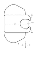
次にガス供給ユニット40の構造について説明する。図5は、ガス供給ユニット40の正面図(+Z方向からガス供給ユニット40を見た図)である。ガス供給ユニット40の形状は略直線形状の長軸42及び43、及び湾曲形状の短軸44及び45を有し、細長形を有する。短軸44及び45には、接続部46及び47がそれぞれ設けられている。接続部46及び47の形状は図7や図8を参照して後述する。なお短軸44及び45は必ずしも湾曲形状でなくてもよく、ガスセンサ30の細長形に略対応した形状であればよい。
Next, the structure of the
図6は、ガス供給ユニット40の裏面図(−Z方向からガス供給ユニット40を見た図)である。ガス供給ユニット40は、上述のように長軸(42、43)及び湾曲形状の短軸(44、45)を持つ細長形である。ガス供給ユニット40は、図1にも示すようにガスセンサ30を覆うようなキャップ形状を持ち、空隙48に酸素ガスが流入する。接続部46は一対構造の係止爪461及び462を有する。係止爪461、462は、ガス供給ユニット40から延伸するチューブ41の取り付け面と同じ面(短軸44)に設けられている。同様に接続部47は一対構造の係止爪471及び472を有する。係止爪471、472は、ガス供給ユニット40から延伸するチューブ41の取り付け面と対向する面(短軸45)に設けられている。空隙48は、キャップ形状(図1に示すようにガスセンサ30を覆う形状)である。ガス供給ユニット40の筐体は、例えばプラスティック等の剛性を有する素材により構成される。
FIG. 6 is a rear view of the gas supply unit 40 (a view of the
空隙48は、ガスセンサ30が挿入される空間である。そのため空隙48のサイズ(図6におけるd4、d5)は、ガスセンサ30と対応する大きさ(例えばガスセンサ30を挿入した際に緩嵌合する大きさ、ガスセンサ30を覆うように保持できる大きさ)とする。
The void 48 is a space into which the
図7は、ガス供給ユニット40の左側面図(−X方向からガス供給ユニット40を見た図)である。接続部47は、−Z側端部に上下方向(上:+Y方向、下:−Y方向)から挟み込むように凸となっている一対の係止爪471及び472を有する。また係止爪471及び472を端部とした窪みである係止穴473が設けられている。この係止穴473には、ガスセンサ30の凸部37が挿入される(詳細は図9を参照して後述し、底面から係止爪471、472までの奥行d6についても後述する。)。
FIG. 7 is a left side view of the gas supply unit 40 (a view of the
図8は、ガス供給ユニット40の右側面図(+X方向からガス供給ユニット40を見た図)である。接続部46は、−Z側端部に上下方向(上:+Y方向、下:−Y方向)から挟み込むように凸となっている一対の係止爪461及び462を有する。また係止爪461及び462を端部とした窪みである係止穴463が設けられている。この係止穴463には、ガスセンサ30の凸部37が挿入される(詳細は図9を参照して後述し、底面から係止爪461、462までの奥行d7についても後述する。)。
FIG. 8 is a right side view of the gas supply unit 40 (a view of the
続いてガスセンサ30とガス供給ユニット40の接続構造について説明する。図9は、ガスセンサ30とガス供給ユニット40を接続した際の右側面図(+X方向からガスセンサ30及びガス供給ユニット40を見た図)である。また図10は、ガスセンサ30とガス供給ユニット40を接続した際の上面図(+Y方向からガスセンサ30及びガス供給ユニット40を見た図)である。図9及び図10の例では、ガスセンサ30の凸部373(図10では接続部46に隠れて不図示)を接続部46に接続する構成を開示している。
Subsequently, a connection structure between the
図3における奥行d1(ガスセンサ30の底面(長軸31)から凸部373までの奥行)は、図8における奥行d7(ガス供給ユニット40の底面(空隙48の端部)から係止爪471、472までの高さ)と略同一である。そのため、図9に示すようにガスセンサ30の凸部373は、係止爪461及び462に挟み込まれるようにして係止される。換言すると係止爪461及び462は、細長の延伸形状(図4、図9)を持つ凸部373の長軸を両端から挟み込むようにして係止する。両端から挟み込むようにして係止することにより、ガス供給ユニット40は両側から強固にガスセンサ30を固定することができる。
The depth d1 (the depth from the bottom surface (long axis 31) of the
図10を参照すると、係止爪461及び462(図10では不図示)は、チューブ41の取り付け面と同面(短軸44)に配置されている。係止爪461及び462(図10では不図示)は、凸部373(図10では不図示)を係止する。これによりチューブ41とケーブル36は、略逆方向に延伸するように配置される。
With reference to FIG. 10, the locking
図11は、ガスセンサ30の凸部373(図10では接続部46に隠れて不図示)を接続部47に接続した際の上面図(+Y方向からガスセンサ30及びガス供給ユニット40を見た図)である。係止爪471及び472は、チューブ41の取り付け面(短軸44)と対向する面(短軸45)に設けられている。係止爪471及び472は、凸部373(図10では不図示)を係止する。これによりチューブ41とケーブル36は、略同方向に延伸するように配置される。
FIG. 11 is a top view of the
なお、図3における奥行d1(ガスセンサ30の底面(長軸31)から凸部373までの奥行)は、図7における奥行d6(ガス供給ユニット40の底面(空隙48の端部)から係止爪461、462までの高さ)と略同一である。そのため、図11に示すようにチューブ41とケーブル36が略同方向に延伸するように両者を接続できる。
Note that the depth d1 (the depth from the bottom surface (long axis 31) of the
続いて本実施の形態にかかるガスセンサキット1の効果について説明する。ガス供給ユニット40は、係止爪(461、462または471、472)を介してガスセンサ30と接続する。係止爪(461、462または471、472)と凸部37を嵌め合わせる操作により、ガス供給ユニット40とガスセンサ30を容易に着脱できる。そのため、何らかの治療途中に酸素投与を行いたくなった場合であっても、ガスセンサ30を取り外すことなく鼻孔に対して酸素投与を行うことができる。
Subsequently, effects of the
係止爪(461、462)は、チューブ41の取り付け面と同面(短軸44)に設けられている。この係止爪(461、462)を用いてガスセンサ30の凸部37と接続することにより、図10に示すようにチューブ41とケーブル36が異なる方向に延伸する。これにより、チューブ41とケーブル36を被験者の両耳にそれぞれ掛けて固定することができる。またチューブ41と接続する酸素供給源と、ガスセンサ30と接続する外部機器と、をベッドの両脇に配置したい場合であっても容易に対応ができる。
The locking claws (461, 462) are provided on the same surface (short shaft 44) as the mounting surface of the
係止爪(471、472)は、チューブ41の取り付け面との対向面(短軸45)に設けられている。この係止爪(471、472)を用いてガスセンサ30の凸部37と接続することにより、図11に示すようにチューブ41とケーブル36が概ね同じ方向に延伸する。内視鏡検査を行う場合などでは、このガスセンサキット1を側臥位で利用することが想定される。側臥位で利用する場合であってもチューブ41とケーブル36が同方向に延伸するため、チューブ41とケーブル36が検査の邪魔になる事が少ない。
The locking claws (471, 472) are provided on the surface (short shaft 45) facing the mounting surface of the
またガス供給ユニット40の係止爪は、図6に示すようにチューブ41の取り付け面と同じ面(短軸44)及び対向面(短軸45)の双方に設けられている(係止爪461、462、471、472)。これにより治療途中でチューブ41の延伸向きを容易に変更することが可能となる。すなわち図10の接続形態と図11の接続形態を容易に切り替えることができる。
Further, the locking claws of the
ガス供給ユニット40は、図1に示すようにガスセンサ30を覆うようなキャップ形状である。これによりガス供給ユニット40とガスセンサ30を接続した場合であっても、ガスセンサキット1をコンパクトで凹凸の少ない形状にできる。またガスセンサ30を覆うようなキャップ形状であるため、ガス供給ユニット40をガスセンサ30に容易に取り付けることができる。
The
以上、本発明者によってなされた発明を実施の形態に基づき具体的に説明したが、本発明は既に述べた実施の形態に限定されるものではなく、その要旨を逸脱しない範囲において種々の変更が可能であることはいうまでもない。 Although the invention made by the present inventor has been specifically described based on the embodiments, the present invention is not limited to the embodiments described above, and various modifications can be made without departing from the scope of the invention. It goes without saying that it is possible.
例えば、接続部46及び接続部47のいずれか一方のみが設けられている構造とすることも可能である。当該構造であっても、ガスセンサ30にガス供給ユニット40を容易に着脱することができる。
For example, it is possible to adopt a structure in which only one of the connecting
また上述の説明ではガス供給ユニット40の係止爪が一対構造であるものとして説明したが必ずしもこれに限られない。ガス供給ユニット40に設けられる係止爪は、ガスセンサ30の凸部37と係り合って接続するものであれば対形状である必要はなく、一方方向から凸部37と係り合って固定するような形状であってもよい。
Further, in the above description, the locking claws of the
またガス供給ユニット40とガスセンサ30は、互いを固定すると共に着脱が可能な着脱機構をそれぞれ有する構成であればよい。例えばガス供給ユニット40に突起があり、ガスセンサ30の窪みに当該突起を嵌め合わせることが出来る構成であってもよい。もしくはガス供給ユニット40に窪みがあり、ガスセンサ30に突起がある構成であってもよい。またガス供給ユニット40とガスセンサ30にそれぞれ磁石を埋め込んでおき、近接した際に互いに引き合うようにして接続するような構成であってもよい。この磁石により固定する形状を図12及び図13に示す。ガスセンサ30は、長軸32に磁石50を有する(図12)。またガス供給ユニット40は、裏面の空隙48に磁石49が設けられている。この磁石49と磁石50が互いに引き合うことによりガスセンサ30とガス供給ユニット40を接続することができる。
Further, the
1 ガスセンサユニット
10 バイトブロック
20 ネーザルアダプタ
21、22 ネーザルチューブ
30 ガスセンサ
31、32 長軸
33、34 短軸
35 凹部
36 ケーブル
37 凸部38 突条
391〜394 位置規制部
40 ガス供給ユニット
41 チューブ
42、43 長軸
44、45 短軸
46、47 接続部
461、462、471、472 係止爪
48 空隙
49 磁石
50 磁石
1
Claims (10)
前記ネーザルアダプタと着脱可能に構成され、前記ネーザルアダプタから導かれた呼気のガス濃度を測定するガスセンサと、
前記ガスセンサを介して前記ネーザルアダプタと着脱可能に構成され、チューブを介して供給された治療ガスを前記被験者に供給するガス供給ユニットと、を備え、
前記ガスセンサは、前記ガス供給ユニットと接続する際に係止される凸部を有し、
前記ガス供給ユニットは、前記ガスセンサと接続する際に前記凸部を係止する少なくとも一つの係止爪を有する、ガスセンサキット。 A nasal adapter placed near the nasal cavity of the subject to guide the subject's exhalation,
A gas sensor configured to be attachable to and detachable from the nasal adapter, and measuring a gas concentration of exhaled gas guided from the nasal adapter ,
A gas supply unit configured to be attachable to and detachable from the nasal adapter via the gas sensor, and supplying a treatment gas supplied via a tube to the subject,
The gas sensor has a convex portion that is locked when connecting to the gas supply unit,
A gas sensor kit, wherein the gas supply unit has at least one locking claw that locks the convex portion when connecting to the gas sensor.
前記係止爪は、前記延伸形状の長軸を両端から挟み込むようにして係止する一対構造である、ことを特徴とする請求項1〜5のいずれか1項に記載のガスセンサキット。 The convex portion is an elongated stretched shape,
The gas sensor kit according to any one of claims 1 to 5, wherein the locking claw has a pair of structures that locks the elongated shape by sandwiching the elongated axis from both ends.
前記ガス供給ユニットは、前記ガスセンサに設けられた凸部を係止する少なくとも一つの係止爪を有する、ガス供給ユニット。 It is connected to a gas sensor that measures the gas concentration of the subject's exhaled air, and while supplying the treatment gas supplied through a tube to the subject, it is also attached to and detached from a nasal adapter placed near the nose of the subject via the gas sensor. A gas supply unit configured to be possible ,
The gas supply unit has at least one locking claw that locks a convex portion provided on the gas sensor.
前記ネーザルアダプタと着脱可能に構成され、前記ネーザルアダプタから導かれた呼気のガス濃度を測定するガスセンサと、
前記ガスセンサを介して前記ネーザルアダプタと着脱可能に構成され、チューブを介して供給された治療ガスを前記被験者に供給するガス供給ユニットと、を備え、
前記ガス供給ユニットと前記ガスセンサは、互いを固定すると共に着脱が可能な着脱機構をそれぞれ有する、ガスセンサキット。 A nasal adapter placed near the nasal cavity of the subject to guide the subject's exhalation,
A gas sensor configured to be attachable to and detachable from the nasal adapter, and measuring a gas concentration of exhaled gas guided from the nasal adapter ,
A gas supply unit configured to be attachable to and detachable from the nasal adapter via the gas sensor, and supplying a treatment gas supplied via a tube to the subject,
A gas sensor kit, wherein each of the gas supply unit and the gas sensor has an attachment/detachment mechanism that fixes the attachment and detachment.
Priority Applications (5)
| Application Number | Priority Date | Filing Date | Title |
|---|---|---|---|
| JP2016117777A JP6746389B2 (en) | 2016-06-14 | 2016-06-14 | Gas sensor kit, gas supply unit |
| CN201780020035.3A CN109069063B (en) | 2016-06-14 | 2017-06-02 | Gas Sensor Kit and Gas Supply Unit |
| US16/087,310 US11576591B2 (en) | 2016-06-14 | 2017-06-02 | Gas sensor kit and gas supply unit |
| EP17731953.0A EP3468466B1 (en) | 2016-06-14 | 2017-06-02 | Gas sensor kit |
| PCT/JP2017/020706 WO2017217264A1 (en) | 2016-06-14 | 2017-06-02 | Gas sensor kit and gas supply unit |
Applications Claiming Priority (1)
| Application Number | Priority Date | Filing Date | Title |
|---|---|---|---|
| JP2016117777A JP6746389B2 (en) | 2016-06-14 | 2016-06-14 | Gas sensor kit, gas supply unit |
Publications (3)
| Publication Number | Publication Date |
|---|---|
| JP2017221310A JP2017221310A (en) | 2017-12-21 |
| JP2017221310A5 JP2017221310A5 (en) | 2019-04-11 |
| JP6746389B2 true JP6746389B2 (en) | 2020-08-26 |
Family
ID=59093595
Family Applications (1)
| Application Number | Title | Priority Date | Filing Date |
|---|---|---|---|
| JP2016117777A Active JP6746389B2 (en) | 2016-06-14 | 2016-06-14 | Gas sensor kit, gas supply unit |
Country Status (5)
| Country | Link |
|---|---|
| US (1) | US11576591B2 (en) |
| EP (1) | EP3468466B1 (en) |
| JP (1) | JP6746389B2 (en) |
| CN (1) | CN109069063B (en) |
| WO (1) | WO2017217264A1 (en) |
Families Citing this family (2)
| Publication number | Priority date | Publication date | Assignee | Title |
|---|---|---|---|---|
| JP7064920B2 (en) | 2018-03-27 | 2022-05-11 | 日本光電工業株式会社 | Respiratory aid |
| GB202019236D0 (en) * | 2020-12-07 | 2021-01-20 | Intersurgical Ag | Improvements relating to respiratory masks |
Family Cites Families (13)
| Publication number | Priority date | Publication date | Assignee | Title |
|---|---|---|---|---|
| US7335164B2 (en) * | 1996-07-15 | 2008-02-26 | Ntc Technology, Inc. | Multiple function airway adapter |
| US6190327B1 (en) * | 1999-05-05 | 2001-02-20 | Nonin Medical, Inc. | Disposable airway adapter for use with a carbon dioxide detector |
| US6629934B2 (en) * | 2000-02-02 | 2003-10-07 | Healthetech, Inc. | Indirect calorimeter for medical applications |
| US7462154B2 (en) | 2001-03-08 | 2008-12-09 | Nihon Kohden Corporation | Sensor for measuring carbon dioxide in respiratory gas |
| JP3924638B2 (en) | 2001-03-08 | 2007-06-06 | 日本光電工業株式会社 | Sensor for measuring carbon dioxide in respiratory air |
| JP4247758B2 (en) * | 2003-02-18 | 2009-04-02 | 日本光電工業株式会社 | Carbon dioxide gas sensor |
| JP5385599B2 (en) | 2008-12-11 | 2014-01-08 | 日本光電工業株式会社 | Byte block |
| JP5576695B2 (en) | 2009-10-28 | 2014-08-20 | 日本光電工業株式会社 | Oxygen mask |
| JP6137823B2 (en) * | 2012-09-04 | 2017-05-31 | 日本光電工業株式会社 | Airway adapter, biological information acquisition system, and oxygen mask |
| WO2014193847A1 (en) * | 2013-05-29 | 2014-12-04 | General Electric Company | Breathing mask for ventilating a patient |
| JP6382497B2 (en) * | 2013-10-09 | 2018-08-29 | 日本光電工業株式会社 | mask |
| JP6628959B2 (en) | 2014-06-02 | 2020-01-15 | 日本光電工業株式会社 | Temperature sensor manufacturing method and temperature sensor |
| CN104398242B (en) * | 2014-11-28 | 2016-07-13 | 中国人民解放军南京军区南京总医院 | Upper airway temperature and humidity detection device and method |
-
2016
- 2016-06-14 JP JP2016117777A patent/JP6746389B2/en active Active
-
2017
- 2017-06-02 CN CN201780020035.3A patent/CN109069063B/en active Active
- 2017-06-02 US US16/087,310 patent/US11576591B2/en active Active
- 2017-06-02 EP EP17731953.0A patent/EP3468466B1/en active Active
- 2017-06-02 WO PCT/JP2017/020706 patent/WO2017217264A1/en not_active Ceased
Also Published As
| Publication number | Publication date |
|---|---|
| EP3468466B1 (en) | 2024-05-08 |
| CN109069063A (en) | 2018-12-21 |
| JP2017221310A (en) | 2017-12-21 |
| WO2017217264A1 (en) | 2017-12-21 |
| CN109069063B (en) | 2021-05-14 |
| US20190099110A1 (en) | 2019-04-04 |
| US11576591B2 (en) | 2023-02-14 |
| EP3468466A1 (en) | 2019-04-17 |
Similar Documents
| Publication | Publication Date | Title |
|---|---|---|
| US12142361B2 (en) | Methods and systems for quantitative colorimetric capnometry | |
| EP2049054B1 (en) | Nasal and oral patient interface | |
| EP2285269B1 (en) | Wireless capnography | |
| US20150217075A1 (en) | Oxygen mask with means to sample expired gases | |
| CN103301540A (en) | Airway adaptor and biological information acquiring system | |
| JP2014064881A (en) | Airway adaptor, biological information acquiring system, and oxygen mask | |
| WO2019130628A1 (en) | Sleep apnea symptom-amelioration assistance tool | |
| JP6746389B2 (en) | Gas sensor kit, gas supply unit | |
| EP3468442B1 (en) | Bite block and gas sensor kit | |
| US11511067B2 (en) | Respiration assistance device | |
| JP6875797B2 (en) | Gas sensor kit and face mounting equipment | |
| TW201735863A (en) | Breath test device | |
| TW201735864A (en) | Breath test system | |
| JP2024152896A (en) | Medical Instruments, Nasal Adapters, and Bite Blocks | |
| RU2266040C2 (en) | Device for estimating influence of breathing onto changes in pulse rate |
Legal Events
| Date | Code | Title | Description |
|---|---|---|---|
| A521 | Request for written amendment filed |
Free format text: JAPANESE INTERMEDIATE CODE: A523 Effective date: 20190301 |
|
| A621 | Written request for application examination |
Free format text: JAPANESE INTERMEDIATE CODE: A621 Effective date: 20190509 |
|
| A131 | Notification of reasons for refusal |
Free format text: JAPANESE INTERMEDIATE CODE: A131 Effective date: 20200527 |
|
| A521 | Request for written amendment filed |
Free format text: JAPANESE INTERMEDIATE CODE: A523 Effective date: 20200706 |
|
| TRDD | Decision of grant or rejection written | ||
| A01 | Written decision to grant a patent or to grant a registration (utility model) |
Free format text: JAPANESE INTERMEDIATE CODE: A01 Effective date: 20200728 |
|
| A61 | First payment of annual fees (during grant procedure) |
Free format text: JAPANESE INTERMEDIATE CODE: A61 Effective date: 20200805 |
|
| R150 | Certificate of patent or registration of utility model |
Ref document number: 6746389 Country of ref document: JP Free format text: JAPANESE INTERMEDIATE CODE: R150 |
|
| R250 | Receipt of annual fees |
Free format text: JAPANESE INTERMEDIATE CODE: R250 |
|
| R250 | Receipt of annual fees |
Free format text: JAPANESE INTERMEDIATE CODE: R250 |
|
| R250 | Receipt of annual fees |
Free format text: JAPANESE INTERMEDIATE CODE: R250 |
|
| RD07 | Notification of extinguishment of power of attorney |
Free format text: JAPANESE INTERMEDIATE CODE: R3D07 |