JP6731158B2 - Non-aqueous secondary battery - Google Patents
Non-aqueous secondary battery Download PDFInfo
- Publication number
- JP6731158B2 JP6731158B2 JP2017042031A JP2017042031A JP6731158B2 JP 6731158 B2 JP6731158 B2 JP 6731158B2 JP 2017042031 A JP2017042031 A JP 2017042031A JP 2017042031 A JP2017042031 A JP 2017042031A JP 6731158 B2 JP6731158 B2 JP 6731158B2
- Authority
- JP
- Japan
- Prior art keywords
- binder
- positive electrode
- linear
- negative electrode
- branched
- Prior art date
- Legal status (The legal status is an assumption and is not a legal conclusion. Google has not performed a legal analysis and makes no representation as to the accuracy of the status listed.)
- Active
Links
Images


Classifications
-
- H—ELECTRICITY
- H01—ELECTRIC ELEMENTS
- H01M—PROCESSES OR MEANS, e.g. BATTERIES, FOR THE DIRECT CONVERSION OF CHEMICAL ENERGY INTO ELECTRICAL ENERGY
- H01M10/00—Secondary cells; Manufacture thereof
- H01M10/04—Construction or manufacture in general
- H01M10/0431—Cells with wound or folded electrodes
-
- H—ELECTRICITY
- H01—ELECTRIC ELEMENTS
- H01M—PROCESSES OR MEANS, e.g. BATTERIES, FOR THE DIRECT CONVERSION OF CHEMICAL ENERGY INTO ELECTRICAL ENERGY
- H01M4/00—Electrodes
- H01M4/02—Electrodes composed of, or comprising, active material
- H01M4/62—Selection of inactive substances as ingredients for active masses, e.g. binders, fillers
- H01M4/621—Binders
- H01M4/622—Binders being polymers
-
- H—ELECTRICITY
- H01—ELECTRIC ELEMENTS
- H01M—PROCESSES OR MEANS, e.g. BATTERIES, FOR THE DIRECT CONVERSION OF CHEMICAL ENERGY INTO ELECTRICAL ENERGY
- H01M10/00—Secondary cells; Manufacture thereof
- H01M10/05—Accumulators with non-aqueous electrolyte
- H01M10/052—Li-accumulators
-
- H—ELECTRICITY
- H01—ELECTRIC ELEMENTS
- H01M—PROCESSES OR MEANS, e.g. BATTERIES, FOR THE DIRECT CONVERSION OF CHEMICAL ENERGY INTO ELECTRICAL ENERGY
- H01M10/00—Secondary cells; Manufacture thereof
- H01M10/05—Accumulators with non-aqueous electrolyte
- H01M10/052—Li-accumulators
- H01M10/0525—Rocking-chair batteries, i.e. batteries with lithium insertion or intercalation in both electrodes; Lithium-ion batteries
-
- H—ELECTRICITY
- H01—ELECTRIC ELEMENTS
- H01M—PROCESSES OR MEANS, e.g. BATTERIES, FOR THE DIRECT CONVERSION OF CHEMICAL ENERGY INTO ELECTRICAL ENERGY
- H01M10/00—Secondary cells; Manufacture thereof
- H01M10/05—Accumulators with non-aqueous electrolyte
- H01M10/056—Accumulators with non-aqueous electrolyte characterised by the materials used as electrolytes, e.g. mixed inorganic/organic electrolytes
- H01M10/0564—Accumulators with non-aqueous electrolyte characterised by the materials used as electrolytes, e.g. mixed inorganic/organic electrolytes the electrolyte being constituted of organic materials only
- H01M10/0565—Polymeric materials, e.g. gel-type or solid-type
-
- H—ELECTRICITY
- H01—ELECTRIC ELEMENTS
- H01M—PROCESSES OR MEANS, e.g. BATTERIES, FOR THE DIRECT CONVERSION OF CHEMICAL ENERGY INTO ELECTRICAL ENERGY
- H01M10/00—Secondary cells; Manufacture thereof
- H01M10/05—Accumulators with non-aqueous electrolyte
- H01M10/056—Accumulators with non-aqueous electrolyte characterised by the materials used as electrolytes, e.g. mixed inorganic/organic electrolytes
- H01M10/0564—Accumulators with non-aqueous electrolyte characterised by the materials used as electrolytes, e.g. mixed inorganic/organic electrolytes the electrolyte being constituted of organic materials only
- H01M10/0566—Liquid materials
- H01M10/0567—Liquid materials characterised by the additives
-
- H—ELECTRICITY
- H01—ELECTRIC ELEMENTS
- H01M—PROCESSES OR MEANS, e.g. BATTERIES, FOR THE DIRECT CONVERSION OF CHEMICAL ENERGY INTO ELECTRICAL ENERGY
- H01M10/00—Secondary cells; Manufacture thereof
- H01M10/05—Accumulators with non-aqueous electrolyte
- H01M10/056—Accumulators with non-aqueous electrolyte characterised by the materials used as electrolytes, e.g. mixed inorganic/organic electrolytes
- H01M10/0564—Accumulators with non-aqueous electrolyte characterised by the materials used as electrolytes, e.g. mixed inorganic/organic electrolytes the electrolyte being constituted of organic materials only
- H01M10/0566—Liquid materials
- H01M10/0568—Liquid materials characterised by the solutes
-
- H—ELECTRICITY
- H01—ELECTRIC ELEMENTS
- H01M—PROCESSES OR MEANS, e.g. BATTERIES, FOR THE DIRECT CONVERSION OF CHEMICAL ENERGY INTO ELECTRICAL ENERGY
- H01M4/00—Electrodes
- H01M4/02—Electrodes composed of, or comprising, active material
- H01M4/62—Selection of inactive substances as ingredients for active masses, e.g. binders, fillers
- H01M4/621—Binders
- H01M4/622—Binders being polymers
- H01M4/623—Binders being polymers fluorinated polymers
-
- H—ELECTRICITY
- H01—ELECTRIC ELEMENTS
- H01M—PROCESSES OR MEANS, e.g. BATTERIES, FOR THE DIRECT CONVERSION OF CHEMICAL ENERGY INTO ELECTRICAL ENERGY
- H01M2300/00—Electrolytes
- H01M2300/0017—Non-aqueous electrolytes
- H01M2300/0025—Organic electrolyte
-
- Y—GENERAL TAGGING OF NEW TECHNOLOGICAL DEVELOPMENTS; GENERAL TAGGING OF CROSS-SECTIONAL TECHNOLOGIES SPANNING OVER SEVERAL SECTIONS OF THE IPC; TECHNICAL SUBJECTS COVERED BY FORMER USPC CROSS-REFERENCE ART COLLECTIONS [XRACs] AND DIGESTS
- Y02—TECHNOLOGIES OR APPLICATIONS FOR MITIGATION OR ADAPTATION AGAINST CLIMATE CHANGE
- Y02E—REDUCTION OF GREENHOUSE GAS [GHG] EMISSIONS, RELATED TO ENERGY GENERATION, TRANSMISSION OR DISTRIBUTION
- Y02E60/00—Enabling technologies; Technologies with a potential or indirect contribution to GHG emissions mitigation
- Y02E60/10—Energy storage using batteries
-
- Y—GENERAL TAGGING OF NEW TECHNOLOGICAL DEVELOPMENTS; GENERAL TAGGING OF CROSS-SECTIONAL TECHNOLOGIES SPANNING OVER SEVERAL SECTIONS OF THE IPC; TECHNICAL SUBJECTS COVERED BY FORMER USPC CROSS-REFERENCE ART COLLECTIONS [XRACs] AND DIGESTS
- Y02—TECHNOLOGIES OR APPLICATIONS FOR MITIGATION OR ADAPTATION AGAINST CLIMATE CHANGE
- Y02P—CLIMATE CHANGE MITIGATION TECHNOLOGIES IN THE PRODUCTION OR PROCESSING OF GOODS
- Y02P70/00—Climate change mitigation technologies in the production process for final industrial or consumer products
- Y02P70/50—Manufacturing or production processes characterised by the final manufactured product
-
- Y—GENERAL TAGGING OF NEW TECHNOLOGICAL DEVELOPMENTS; GENERAL TAGGING OF CROSS-SECTIONAL TECHNOLOGIES SPANNING OVER SEVERAL SECTIONS OF THE IPC; TECHNICAL SUBJECTS COVERED BY FORMER USPC CROSS-REFERENCE ART COLLECTIONS [XRACs] AND DIGESTS
- Y02—TECHNOLOGIES OR APPLICATIONS FOR MITIGATION OR ADAPTATION AGAINST CLIMATE CHANGE
- Y02T—CLIMATE CHANGE MITIGATION TECHNOLOGIES RELATED TO TRANSPORTATION
- Y02T10/00—Road transport of goods or passengers
- Y02T10/60—Other road transportation technologies with climate change mitigation effect
- Y02T10/70—Energy storage systems for electromobility, e.g. batteries
Landscapes
- Chemical & Material Sciences (AREA)
- Chemical Kinetics & Catalysis (AREA)
- Electrochemistry (AREA)
- General Chemical & Material Sciences (AREA)
- Engineering & Computer Science (AREA)
- Manufacturing & Machinery (AREA)
- General Physics & Mathematics (AREA)
- Inorganic Chemistry (AREA)
- Condensed Matter Physics & Semiconductors (AREA)
- Physics & Mathematics (AREA)
- Dispersion Chemistry (AREA)
- Materials Engineering (AREA)
- Battery Electrode And Active Subsutance (AREA)
- Secondary Cells (AREA)
Description
本発明は、非水系二次電池に関する。 The present invention relates to a non-aqueous secondary battery.
リチウムイオン二次電池等の非水系二次電池では、更なる電池性能の向上が検討されている。これに関連する先行技術として、特許文献1の段落0015には、非水電解液にN,N−ジメチルホルムアミド(DMF)等の非水溶媒を使用することが記載されている。特許文献1によれば、段落0015に記載されるDMF等の非水溶媒は、イオン伝導性が高い。このため、充放電容量の向上等に有用である。
For non-aqueous secondary batteries such as lithium-ion secondary batteries, further improvement in battery performance is being studied. As a related art related to this, paragraph 0015 of
しかしながら、本発明者の検討によれば、DMFは電子吸引性が高く、電極に含まれるバインダ成分(例えば、ポリフッ化ビニリデン)を溶解させてしまうことがある。かかる場合、電極の形状を安定に保持することができず、電池性能が低下するという課題があった。 However, according to the study by the present inventor, DMF has a high electron-attracting property and may dissolve a binder component (for example, polyvinylidene fluoride) contained in the electrode. In such a case, there is a problem that the shape of the electrode cannot be stably maintained and the battery performance is deteriorated.
本発明は、かかる事情に鑑みてなされたものであり、その目的は、非水電解液にDMFを含み、電池性能の向上した非水系二次電池を提供することである。 The present invention has been made in view of such circumstances, and an object thereof is to provide a non-aqueous secondary battery that contains DMF in a non-aqueous electrolyte and has improved battery performance.
本発明により、正極と負極と非水電解液とを備える非水系二次電池が提供される。上記非水電解液は、非水溶媒と支持塩とを含む。上記非水溶媒は、N,N−ジメチルホルムアミドを含む。上記支持塩の濃度は、1mol/L以上2mol/L以下である。上記正極および上記負極の少なくとも一方は、集電体と、上記集電体の上に固着され、活物質とバインダとを含む電極合材層と、を備える。上記バインダは、ポリエチレングリコール骨格を有する4分岐のプレポリマーがウレタン結合した構造の網目状の高分子化合物を含む。 The present invention provides a non-aqueous secondary battery including a positive electrode, a negative electrode, and a non-aqueous electrolytic solution. The non-aqueous electrolyte solution contains a non-aqueous solvent and a supporting salt. The non-aqueous solvent contains N,N-dimethylformamide. The concentration of the supporting salt is 1 mol/L or more and 2 mol/L or less. At least one of the positive electrode and the negative electrode includes a current collector, and an electrode mixture layer fixed on the current collector and containing an active material and a binder. The binder contains a network polymer compound having a urethane-bonded 4-branched prepolymer having a polyethylene glycol skeleton.
非水電解液にN,N−ジメチルホルムアミド(DMF)を含むことで、導電性を向上することができる。また、電極合材層中に上記バインダを含むことで、DMFによるバインダの溶解を抑制して、電極の形状を安定的に維持することができる。さらに、上記バインダを含む電極では、保液性が向上している。このことにより、例えば非水電解液が電極合材層から押し出され易いハイレート充放電を行う場合であっても、電極合材層中に好適に非水電解液を維持することができる。これらの効果が相俟って、上記非水系二次電池では、電池抵抗を低く抑えると共に、ハイレート耐性を向上することができる。 The conductivity can be improved by including N,N-dimethylformamide (DMF) in the non-aqueous electrolyte. Further, by including the binder in the electrode mixture layer, dissolution of the binder by DMF can be suppressed and the shape of the electrode can be stably maintained. Further, the electrode containing the binder has improved liquid retention. Thus, for example, even when performing high-rate charging/discharging in which the non-aqueous electrolyte solution is easily pushed out from the electrode mixture layer, the non-aqueous electrolyte solution can be preferably maintained in the electrode mixture layer. In combination with these effects, in the non-aqueous secondary battery, the battery resistance can be suppressed low and the high rate resistance can be improved.
なお、特許文献2の請求項1等には、ポリエチレングリコール骨格を有するポリマーがアミド結合等で架橋され網目構造を構成している非水系ゲル電解質、および、当該非水系ゲル電解質を備えた非水系二次電池が開示されている。しかしながら、特許文献2には、電極合材層にバインダとして上記のような高分子化合物を含ませることについて、何ら開示も示唆もされていない。また、特許文献2には、上記4分岐のプレポリマーをウレタン結合で架橋した高分子化合物についても、何ら開示も示唆もされていない。
In addition, in
好適な一態様では、上記高分子化合物が、以下の化学式(I),(II):
で示される2種類のプレポリマーがウレタン結合した構造を有する。これにより、上記高分子化合物を好適に実現することができる。
In a preferred embodiment, the polymer compound has the following chemical formulas (I) and (II):
Has a structure in which two types of prepolymers represented by are urethane-bonded. Thereby, the above-mentioned polymer compound can be preferably realized.
好適な一態様では、上記電極合材層の全体を100質量%としたときに、上記高分子化合物の割合が2質量%以上である。これにより、電極合材層の保液性をより良く高めて、ここに開示される技術の効果をより高いレベルで発揮することができる。 In a preferred aspect, the ratio of the polymer compound is 2% by mass or more when the total amount of the electrode mixture layer is 100% by mass. Thereby, the liquid retaining property of the electrode composite material layer can be further improved, and the effect of the technique disclosed herein can be exhibited at a higher level.
好適な一態様では、上記支持塩が、リチウムビス(フルオロスルホニル)イミドを含む。これにより、電池抵抗をより低く抑えることができる。 In a suitable aspect, the supporting salt comprises lithium bis(fluorosulfonyl)imide. Thereby, the battery resistance can be further suppressed.
好適な一態様では、上記バインダが、フッ素化樹脂およびゴム類の少なくとも1方をさらに含む。これにより、集電体と電極合材層との一体性、および、電極合材層の形状維持性のうちの少なくとも1方を、より良く高めることができる。 In a preferred aspect, the binder further contains at least one of a fluorinated resin and rubbers. Thereby, at least one of the integrity of the current collector and the electrode mixture layer and the shape retention of the electrode mixture layer can be improved.
以下、適宜図面を参照しながら、本発明の好適な実施形態を説明する。なお、本明細書において特に言及している事項以外の事柄であって本発明の実施に必要な事柄は、当該分野における従来技術に基づく当業者の設計事項として把握され得る。本発明は、本明細書に開示されている内容と当該分野における技術常識とに基づいて実施することができる。また、以下の図面において、同じ作用を奏する部材・部位には同じ符号を付して説明し、重複する説明は省略または簡略化することがある。また、各図における寸法関係(長さ、幅、厚さ等)は必ずしも実際の寸法関係を反映するものではない。 Hereinafter, preferred embodiments of the present invention will be described with reference to the drawings as appropriate. It should be noted that matters other than matters particularly referred to in the present specification and matters necessary for implementing the present invention can be grasped as design matters of a person skilled in the art based on conventional technology in the field. The present invention can be carried out based on the contents disclosed in this specification and the common general technical knowledge in the field. Further, in the following drawings, members/sites having the same action will be described with the same reference numerals, and redundant description may be omitted or simplified. In addition, the dimensional relationships (length, width, thickness, etc.) in each drawing do not necessarily reflect the actual dimensional relationships.
<非水系二次電池>
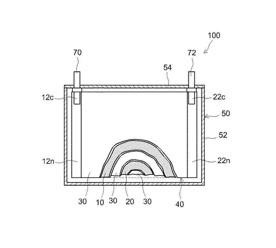
図1は、非水系二次電池100の内部構造を模式的に示す縦断面図である。非水系二次電池100は、電極体40と、図示しない非水電解液とが、電池ケース50に収容されて構成されている。
<Non-aqueous secondary battery>
FIG. 1 is a vertical cross-sectional view schematically showing the internal structure of the non-aqueous
電池ケース50は、上端が開口された扁平な直方体形状(角形)の電池ケース本体52と、その開口を塞ぐ蓋板54と、を備えている。電池ケース50の材質は、特に限定されないが、例えば、アルミニウム等の軽量な金属である。なお、電池ケース50の外形は、円筒形状やコイン形状等であってもよい。電池ケース50は、ラミネートフィルム製の袋体形状であってもよい。蓋体54には、図示しない注液口が設けられている。蓋板54からは、外部接続用の正極端子70と負極端子72とが突出している。
The
電極体40は、帯状の正極10と、帯状の負極20と、帯状のセパレータ30とを備えている。電極体40は、正極10と負極20とがセパレータ30を介在させた状態で重ねられ、長手方向に捲回されて構成されている。電極体40は、捲回電極体である。電極体40の外形は、扁平形状である。電極体40は、捲回軸に直交する断面において、略角丸長方形状を有している。ただし、電極体40は、矩形状の正極と矩形状の負極とが矩形状のセパレータを介在させた状態で積層されて構成されている板状の積層電極体であってもよい。
The
正極10は、帯状の正極集電体と、その表面に固着された正極合材層とを備えている。正極集電体としては、導電性の良好な金属(例えばアルミニウム)からなる導電性部材が好適である。正極合材層は、正極集電体の表面に、正極集電体の長手方向に沿って形成されている。正極集電体の幅方向の一方(図1の左側)の端部には、正極合材層の形成されていない正極合材層非形成部分12nが設けられている。正極10は、正極合材層非形成部分12nに付設された正極集電板12cを介して正極端子70と電気的に接続されている。
The
正極合材層は、少なくとも正極活物質と正極用バインダとを含んでいる。
正極活物質としては、非水系二次電池の正極に使用し得ることが知られている各種の活物質材料を、特に限定なく1種または2種以上用いることができる。一好適例として、リチウムニッケルマンガン複合酸化物、リチウムニッケルマンガンコバルト複合酸化物等のリチウム遷移金属複合酸化物が挙げられる。
The positive electrode mixture layer contains at least a positive electrode active material and a positive electrode binder.
As the positive electrode active material, various active material materials known to be used for the positive electrode of the non-aqueous secondary battery can be used alone or in combination of two or more without particular limitation. One preferable example is a lithium transition metal composite oxide such as a lithium nickel manganese composite oxide or a lithium nickel manganese cobalt composite oxide.
正極用バインダは、正極集電体の上に正極合材層を固着させる第1の機能と、正極合材層の形状を維持する第2の機能とに加えて、正極合材層内に非水電解液を保持する第3の機能を有する。正極用バインダは、網目状の高分子化合物を含んでいる。この高分子化合物(以下、「Tetra−PEGバインダ」と略称することがある。)は、ポリエチレングリコール骨格を有する4分岐のプレポリマーがウレタン結合した構造を有する。なお、Tetra−PEGバインダについては、後ほど詳述する。正極用バインダは、Tetra−PEGバインダのみで構成されていてもよいし、Tetra−PEGバインダに加えて、非水系二次電池に使用し得ることが知られている各種のバインダを1種または2種以上含んでもよい。そのようなバインダの一好適例として、ポリフッ化ビニリデン(PVdF)、ポリテトラフルオロエチレン(PTFE)等のフッ素化樹脂や、ポリエチレンオキサイド(PEO)等のポリアルキレンオキサイドが挙げられる。なかでも、DMFに対する溶解性が低いこと等から、ポリテトラフルオロエチレンを好適に用いることができる。 The positive electrode binder has a first function of fixing the positive electrode mixture layer on the positive electrode current collector, a second function of maintaining the shape of the positive electrode mixture layer, and a non-existence in the positive electrode mixture layer. It has a third function of holding the water electrolyte. The binder for the positive electrode contains a network polymer compound. This polymer compound (hereinafter, may be abbreviated as “Tetra-PEG binder”) has a structure in which a 4-branched prepolymer having a polyethylene glycol skeleton is urethane-bonded. The Tetra-PEG binder will be described in detail later. The binder for the positive electrode may be composed of only the Tetra-PEG binder, or in addition to the Tetra-PEG binder, one or two kinds of various binders known to be used in the non-aqueous secondary battery may be used. You may include 1 or more types. Preferred examples of such a binder include fluorinated resins such as polyvinylidene fluoride (PVdF) and polytetrafluoroethylene (PTFE), and polyalkylene oxides such as polyethylene oxide (PEO). Among them, polytetrafluoroethylene can be preferably used because of its low solubility in DMF.
上記第1、第2の機能を高いレベルで発揮する観点からは、正極用バインダとして、Tetra−PEGバインダと他のバインダとを併用することが好ましい。一好適例として、Tetra−PEGバインダとフッ素化樹脂との組み合わせが挙げられる。Tetra−PEGバインダとフッ素化樹脂との含有比率は、例えば、Tetra−PEGバインダ:フッ素化樹脂=1:2〜2:1とするとよい。 From the viewpoint of exhibiting the first and second functions at a high level, it is preferable to use the Tetra-PEG binder in combination with another binder as the binder for the positive electrode. One preferable example is a combination of Tetra-PEG binder and a fluorinated resin. The content ratio of the Tetra-PEG binder and the fluorinated resin may be, for example, Tetra-PEG binder:fluorinated resin=1:2 to 2:1.
正極合材層は、正極活物質と正極用バインダ以外の成分、例えば導電材等の各種添加剤を含んでいてもよい。導電材としては、例えば、アセチレンブラックやケッチェンブラック等のカーボンブラック、活性炭、黒鉛等の炭素材料が例示される。 The positive electrode mixture layer may contain components other than the positive electrode active material and the positive electrode binder, for example, various additives such as a conductive material. Examples of the conductive material include carbon black such as acetylene black and Ketjen black, and carbon materials such as activated carbon and graphite.
正極合材層の全体を100質量%としたときに、正極活物質の占める割合は、特に限定されないが、高エネルギー密度を実現する観点等から、概ね50質量%以上、典型的には80質量%以上、好ましくは90質量%以上であって、概ね98質量%以下、典型的には95質量%以下であるとよい。
正極合材層の全体を100質量%としたときに、正極用バインダの占める割合は、特に限定されないが、上記第1〜第3の機能をより良くバランスする観点から、概ね1質量%以上、典型的には3質量%以上、例えば5質量%以上であって、概ね10質量%以下、典型的には8質量%以下であるとよい。また、正極合材層の全体を100質量%としたときに、Tetra−PEGバインダの占める割合は、特に限定されないが、上記第1〜第3の機能をより良くバランスする観点から、概ね1質量%以上、好ましくは2質量%以上であって、概ね10質量%以下、例えば5質量%以下であるとよい。
The proportion of the positive electrode active material is not particularly limited when the total amount of the positive electrode mixture layer is 100% by mass, but from the viewpoint of achieving a high energy density, it is generally 50% by mass or more, and typically 80% by mass. % Or more, preferably 90% by mass or more, and generally 98% by mass or less, typically 95% by mass or less.
When the entire positive electrode mixture layer is 100% by mass, the proportion of the binder for the positive electrode is not particularly limited, but from the viewpoint of better balancing the first to third functions, it is generally 1% by mass or more, It is typically 3% by mass or more, for example 5% by mass or more, and is generally 10% by mass or less, typically 8% by mass or less. The proportion of the Tetra-PEG binder is not particularly limited when the total amount of the positive electrode mixture layer is 100% by mass, but is approximately 1% by mass from the viewpoint of better balancing the first to third functions. % Or more, preferably 2% by mass or more and approximately 10% by mass or less, for example 5% by mass or less.
負極20は、帯状の負極集電体と、その表面に固着された負極合材層とを備えている。負極集電体としては、導電性の良好な金属(例えば銅)からなる導電性材料が好適である。負極合材層は、負極集電体の表面に、負極集電体の長手方向に沿って形成されている。負極集電体の幅方向の一方(図1の右側)の端部には、負極合材層の形成されていない負極合材層非形成部分22nが設けられている。負極20は、負極合材層非形成部分22nに付設された負極集電板22cを介して負極端子72と電気的に接続されている。
The
負極合材層は、少なくとも負極活物質と負極用バインダとを含んでいる。
負極活物質としては、非水系二次電池の負極に使用し得ることが知られている各種の活物質材料を、特に限定なく1種または2種以上用いることができる。一好適例として、天然黒鉛、人造黒鉛、非晶質コート黒鉛等の黒鉛系炭素が挙げられる。なお、本明細書において「黒鉛系炭素」とは、黒鉛の占める割合が概ね50質量%以上、典型的には80質量%以上の材料である。
The negative electrode mixture layer includes at least a negative electrode active material and a negative electrode binder.
As the negative electrode active material, various active material materials known to be usable for the negative electrode of the non-aqueous secondary battery may be used alone or in combination of two or more without particular limitation. As a preferred example, graphite-based carbon such as natural graphite, artificial graphite, and amorphous coated graphite can be mentioned. In the present specification, “graphite-based carbon” is a material in which the proportion of graphite is approximately 50% by mass or more, and typically 80% by mass or more.
負極用バインダは、負極集電体の上に負極合材層を固着させる第1の機能と、負極合材層の形状を維持する第2の機能とに加えて、負極合材層内に非水電解液を保持する第3の機能を有する。負極用バインダは、Tetra−PEGバインダを含んでいる。なお、Tetra−PEGバインダについては、後ほど詳述する。負極用バインダは、Tetra−PEGバインダのみで構成されていてもよいし、Tetra−PEGバインダに加えて、非水系二次電池に使用し得ることが知られている各種のバインダを1種または2種以上含んでもよい。そのようなバインダの一好適例として、スチレンブタジエンゴム(SBR)、アクリロニトリル−ブタジエン共重合体ゴム(NBR)、アクリロニトリル−ブタジエン−イソプレン共重合体ゴム(NBIR)等のゴム類、ポリフッ化ビニリデン(PVdF)、ポリテトラフルオロエチレン(PTFE)等のフッ素化樹脂が挙げられる。なかでも、DMFに対する溶解性が低いこと等から、ゴム類、例えば主鎖に二重結合を含むジエン系ゴム、好ましくはブタジエンが全体の50モル%以上を占めるブタジエン系ゴムを好適に用いることができる。 The negative electrode binder has a first function of fixing the negative electrode mixture layer on the negative electrode current collector, a second function of maintaining the shape of the negative electrode mixture layer, and a non-existence in the negative electrode mixture layer. It has a third function of holding the water electrolyte. The binder for the negative electrode contains a Tetra-PEG binder. The Tetra-PEG binder will be described later in detail. The binder for the negative electrode may be composed of only the Tetra-PEG binder, or in addition to the Tetra-PEG binder, one or two kinds of various binders known to be usable in the non-aqueous secondary battery may be used. You may include 1 or more types. Preferred examples of such a binder include rubbers such as styrene-butadiene rubber (SBR), acrylonitrile-butadiene copolymer rubber (NBR), acrylonitrile-butadiene-isoprene copolymer rubber (NBIR), polyvinylidene fluoride (PVdF). ), polytetrafluoroethylene (PTFE), and other fluorinated resins. Among them, rubbers, for example, diene rubbers having a double bond in the main chain, preferably butadiene rubbers in which butadiene accounts for 50 mol% or more of the total are preferably used because of their low solubility in DMF. it can.
上記第1、第2の機能を高いレベルで発揮する観点からは、負極用バインダとして、Tetra−PEGバインダと他のバインダとを併用することが好ましい。一好適例として、Tetra−PEGバインダとゴム類との組み合わせが挙げられる。Tetra−PEGバインダとゴム類との含有比率は、典型的には、ゴム類よりもTetra−PEGバインダの方が多く、例えば、Tetra−PEGバインダ:ゴム類=2:1〜20:1とするとよい。 From the viewpoint of exhibiting the first and second functions at a high level, it is preferable to use a Tetra-PEG binder in combination with another binder as the negative electrode binder. One preferable example is a combination of Tetra-PEG binder and rubbers. The content ratio of the Tetra-PEG binder and the rubbers is typically larger in the Tetra-PEG binder than in the rubbers. For example, when the Tetra-PEG binder:rubbers is 2:1 to 20:1. Good.
負極合材層は、負極活物質と負極用バインダ以外の成分、例えば、増粘剤、分散剤、導電材等の各種添加剤を含んでいてもよい。増粘剤としては、例えば、カルボキシメチルセルロース(CMC)やメチルセルロース(MC)等のセルロース類が例示される。導電材としては、例えば、カーボンブラック、活性炭等の非晶質炭素材料が例示される。 The negative electrode mixture layer may contain components other than the negative electrode active material and the binder for the negative electrode, for example, various additives such as a thickener, a dispersant, and a conductive material. Examples of the thickening agent include celluloses such as carboxymethyl cellulose (CMC) and methyl cellulose (MC). Examples of the conductive material include amorphous carbon materials such as carbon black and activated carbon.
負極合材層の全体を100質量%としたときに、負極活物質の占める割合は、特に限定されないが、高エネルギー密度を実現する観点等から、概ね50質量%以上、典型的には80質量%以上、好ましくは90質量%以上であって、概ね99質量%以下、典型的には98質量%以下であるとよい。
負極合材層の全体を100質量%としたときに、負極用バインダの占める割合は、特に限定されないが、上記第1〜第3の機能をより良くバランスする観点から、概ね0.5質量%以上、典型的には1質量%以上、例えば2質量%以上であって、概ね10質量%以下、典型的には6質量%以下であるとよい。また、負極合材層の全体を100質量%としたときに、Tetra−PEGバインダの占める割合は、特に限定されないが、上記第1〜第3の機能をより良くバランスする観点から、概ね1質量%以上、好ましくは2質量%以上であって、概ね10質量%以下、例えば5質量%以下であるとよい。負極合材層に占めるTetra−PEGバインダの割合は、正極合材層に占めるTetra−PEGバインダの割合と同じであってもよいし、異なっていてもよい。
When the total amount of the negative electrode mixture layer is 100% by mass, the ratio of the negative electrode active material is not particularly limited, but from the viewpoint of achieving high energy density, it is generally 50% by mass or more, typically 80% by mass. % Or more, preferably 90% by mass or more, and generally 99% by mass or less, typically 98% by mass or less.
The ratio of the binder for the negative electrode is not particularly limited when the total amount of the negative electrode mixture layer is 100% by mass, but is generally 0.5% by mass from the viewpoint of better balancing the first to third functions. As described above, it is typically 1% by mass or more, for example, 2% by mass or more, and is generally 10% by mass or less, typically 6% by mass or less. The proportion of the Tetra-PEG binder is not particularly limited when the total amount of the negative electrode mixture layer is 100% by mass, but from the viewpoint of better balancing the first to third functions, it is approximately 1% by mass. % Or more, preferably 2% by mass or more and approximately 10% by mass or less, for example 5% by mass or less. The proportion of Tetra-PEG binder in the negative electrode mixture layer may be the same as or different from the proportion of Tetra-PEG binder in the positive electrode mixture layer.
セパレータ30は、正極10の正極合材層と、負極20の負極合材層との間に配置されている。セパレータ30は、帯状の樹脂シートである。樹脂シートとしては、例えば、ポリエチレン(PE)やポリプロピレン(PP)等のポリオレフィン、ポリエステル、ポリアミド等の樹脂からなる多孔質シートが例示される。セパレータ30は、単層構造であってもよく、材質や性状(厚みや空孔率等)の異なる2種以上の樹脂シートが積層された多層構造であってもよい。また、セパレータ30は、その表面に耐熱層(Heat Resistant Layer:HRL層)を備えていてもよい。
The
非水電解液は、非水溶媒と支持塩とを含んでいる。非水電解液は、非水系二次電池100の使用温度範囲内(典型的には、−20〜+60℃の温度範囲、例えば、−10〜50℃の温度範囲)において液状である。非水電解液の粘度(25℃でB型回転粘度計を用いて測定される粘度。)は、イオン伝導性をより良く高める観点から、例えば、10mPa・s以下、好ましくは5mPa・s以下であるとよい。 The non-aqueous electrolytic solution contains a non-aqueous solvent and a supporting salt. The non-aqueous electrolyte solution is liquid within the operating temperature range of the non-aqueous secondary battery 100 (typically, the temperature range of −20 to +60° C., for example, the temperature range of −10 to 50° C.). The viscosity of the non-aqueous electrolytic solution (viscosity measured using a B-type rotational viscometer at 25° C.) is, for example, 10 mPa·s or less, preferably 5 mPa·s or less, from the viewpoint of improving the ionic conductivity. Good to have.
非水溶媒は、N,N−ジメチルホルムアミド(DMF)を含んでいる。非水溶媒は、DMFのみで構成されていてもよいし、典型的にはDMFよりも少ない体積割合で、非水系二次電池に使用し得ることが知られている各種の非水溶媒を1種または2種以上含んでもよい。そのような非水溶媒の一好適例として、カーボネート類、エステル類、エーテル類、ニトリル類、スルホン類、ラクトン類等の有機溶媒が挙げられる。カーボネート類としては、例えば、エチレンカーボネート(EC)、ジエチルカーボネート(DEC)、ジメチルカーボネート(DMC)、エチルメチルカーボネート(EMC)等が例示される。 The non-aqueous solvent contains N,N-dimethylformamide (DMF). The non-aqueous solvent may be composed only of DMF, and typically, various non-aqueous solvents known to be used in a non-aqueous secondary battery are used in a volume ratio smaller than that of DMF. One kind or two or more kinds may be included. Suitable examples of such a non-aqueous solvent include organic solvents such as carbonates, esters, ethers, nitriles, sulfones and lactones. Examples of the carbonates include ethylene carbonate (EC), diethyl carbonate (DEC), dimethyl carbonate (DMC), ethyl methyl carbonate (EMC) and the like.
支持塩は、非水溶媒中で解離して電荷担体イオンを生成する。支持塩としては、例えば、リチウム塩やナトリウム塩等が例示される。リチウム塩の一好適例として、リチウムビス(フルオロスルホニル)イミド(LiFSI)、LiPF6、LiBF4等が挙げられる。なかでも、非水電解液のイオン伝導性をより良く高める観点から、LiFSIを好適に用いることができる。本実施形態において、支持塩の濃度は、1〜2mol/L、好ましくは1〜1.5mol/Lである。これにより、非水電解液の粘度が高くなり過ぎることを抑制して、イオン伝導性を高めることができる。その結果、電池抵抗をより良く低減することができる。 The supporting salt dissociates in a non-aqueous solvent to generate charge carrier ions. Examples of the supporting salt include lithium salt and sodium salt. Examples of suitable lithium salts include lithium bis(fluorosulfonyl)imide (LiFSI), LiPF 6 , and LiBF 4 . Among them, LiFSI can be preferably used from the viewpoint of further improving the ion conductivity of the non-aqueous electrolyte. In this embodiment, the concentration of the supporting salt is 1 to 2 mol/L, preferably 1 to 1.5 mol/L. As a result, it is possible to suppress the viscosity of the non-aqueous electrolytic solution from becoming too high, and to improve the ion conductivity. As a result, the battery resistance can be further reduced.
図2には、3種類の非水電解液(電解液A〜C)について、Liイオン濃度と導電率との関係を示している。なお、電解液Aは、DMF(非水溶媒)中に、LiPF6(支持塩)を含む電解液である。電解液Bは、DMF(非水溶媒)中に、LiFSI(支持塩)を含む電解液である。電解液Cは、ECとDMCとEMCとの混合溶媒中に、LiPF6(支持塩)を含む電解液である。図2に示すように、非水溶媒がDMFである電解液A,Bでは、非水溶媒がカーボネート類である電解液Cに比べて、相対的に導電率が高い。例えばLiイオン濃度が1.1mol/Lの位置では、電解液A,Bの導電率が、電解液Cの概ね2倍である。また、電解液A,Bでは、電解液Cに比べて、Liイオン濃度の変化に対する導電率の変化が小さい。
これらのことから、非水溶媒としてDMFを含み、支持塩の濃度が1〜2mol/Lである非水系二次電池100では、電池抵抗をより良く低減することができる。また、優れたハイレート耐性を実現することができる。
FIG. 2 shows the relationship between the Li ion concentration and the conductivity with respect to the three types of nonaqueous electrolytic solutions (electrolytic solutions A to C). The electrolytic solution A is an electrolytic solution containing LiPF 6 (supporting salt) in DMF (non-aqueous solvent). The electrolytic solution B is an electrolytic solution containing LiFSI (supporting salt) in DMF (non-aqueous solvent). The electrolytic solution C is an electrolytic solution containing LiPF 6 (supporting salt) in a mixed solvent of EC, DMC, and EMC. As shown in FIG. 2, the electrolytic solutions A and B in which the non-aqueous solvent is DMF have relatively higher conductivity than the electrolytic solution C in which the non-aqueous solvent is carbonates. For example, at the position where the Li ion concentration is 1.1 mol/L, the conductivity of the electrolytic solutions A and B is almost twice that of the electrolytic solution C. Further, in the electrolytic solutions A and B, the change in conductivity with respect to the change in Li ion concentration is smaller than that in the electrolytic solution C.
From these facts, in the non-aqueous
<Tetra−PEGバインダ>
ここで、正極10の正極合材層と、負極20の負極合材層とにそれぞれ含まれているTetra−PEGバインダについて説明する。Tetra−PEGバインダは、ポリエチレングリコール骨格を有する4分岐のプレポリマーがウレタン結合(−O−C(=O)−NH−)で架橋された構造を有する。Tetra−PEGバインダは、網目構造を有する高分子化合物である。Tetra−PEGバインダは、典型的には、所謂、ゲル状である。Tetra−PEGバインダは、親水性(撥油性)が高く、DMFに対する溶解性が低く抑えられている。その結果、正極10および負極20では、その形状が安定的に維持される。
<Tetra-PEG binder>
Here, the Tetra-PEG binder contained in each of the positive electrode mixture layer of the
Tetra−PEGバインダは、電荷の片寄りが大きなウレタン結合を有する。Tetra−PEGバインダの電荷の片寄りは、例えばアミド結合(−C(=O)−N−)よりも大きなものである。そのため、Tetra−PEGバインダは、例えば特許文献2に記載されるようなアミド結合を有する高分子化合物に比べ、電荷担体イオンを引きつけて捕捉する力が強い。このことにより、電極合材層と非水電解液との界面で、電荷担体イオンの濃度をより良く高めることができ、界面抵抗を高いレベルで低減することができる。さらに、Tetra−PEGバインダは、電極合材層の保液性をも向上することができる。したがって、例えばハイレート充放電に伴って正極10および負極20が大きく膨張収縮する場合にも、電極合材層中に非水電解液をより良く維持することができる。このことにより、所謂、液枯れの発生を抑制すると共に、ハイレート耐性を向上することができる。
The Tetra-PEG binder has a urethane bond with a large deviation of charges. The deviation of the charge of the Tetra-PEG binder is larger than that of an amide bond (-C(=O)-N-), for example. Therefore, the Tetra-PEG binder has a stronger force of attracting and capturing charge carrier ions than a polymer compound having an amide bond as described in
好適な一態様において、Tetra−PEGバインダは、2つの4分岐の炭素原子が、以下の結合:−〔CH2−O−(CH2CH2O)n1−R1〕−O−C(=O)−NH−〔R2−(OCH2CH2)n2−O−CH2〕−;によって相互に結合された構造を有する。Tetra−PEGバインダは、例えば、次の構造部分:C−〔CH2−O−(CH2CH2O)n1−R1−O−C(=O)−NH〕4;を有する。 In one preferred embodiment, Tetra-PEG binder two four branches carbon atoms, following coupling: - [CH 2 -O- (CH 2 CH 2 O) n1 -R 1 ] -O-C (= O) -NH- [R 2 - (OCH 2 CH 2 ) n2 -O-CH 2 ] -; having mutually coupled structure by. Tetra-PEG binder, for example, the following structural portion: C-[CH 2 -O- (CH 2 CH 2 O) n1 -R 1 -O-C (= O) -NH ] 4; having.
上記n1,n2は、それぞれ独立して、3以上の整数である。本発明者の検討によれば、上記構成により、2つの4分岐の炭素原子間(C−C間)の距離を、溶媒和された電荷担体イオンの3量体よりも大きくすることができる。その結果、電荷担体イオンの透過性を高めることができる。電荷担体イオンの透過性を向上する観点からは、n1,n2が、典型的には10以上、例えば20以上であるとよい。また、網目構造の強靭性をより良く高める観点からは、n1,n2が、概ね300以下、典型的には200以下、例えば100以下であるとよい。また、網目構造の均質性を高める観点からは、n1,n2が概ね同じ(例えばn1とn2の差が5以内)であるとよい。より好ましくは、n1,n2が同一であるとよい。 The above n 1 and n 2 are each independently an integer of 3 or more. According to the study of the present inventor, with the above-described configuration, the distance between two 4-branched carbon atoms (between C and C) can be made larger than that of the solvated trimer of charge carrier ions. As a result, the permeability of charge carrier ions can be increased. From the viewpoint of improving the permeability of charge carrier ions, n 1 and n 2 are typically 10 or more, for example, 20 or more. Further, from the viewpoint of further improving the toughness of the network structure, n 1 and n 2 may be approximately 300 or less, typically 200 or less, for example 100 or less. Further, from the viewpoint of improving the homogeneity of the mesh structure, it is preferable that n 1 and n 2 are substantially the same (for example, the difference between n 1 and n 2 is within 5). More preferably, n 1 and n 2 are the same.
上記R1,R2は、それぞれ独立して、直鎖又は分岐の炭素数が1〜7(例えば1〜4)のアルキレン基、直鎖又は分岐の炭素数が2〜7(例えば1〜4)のアルケニレン基、−NH−R15−、−CO−R15−、−R16−O−R17−、−R16−NH−R17−、−R16−C(=O)O−R17−、−R16−C(=O)O−NH−R17−、−R16−CO−R17−、又は、−R16−CO−NH−R17−である。ここで、R15は、直鎖又は分岐の炭素数が1〜7のアルキレン基を表し、R16は、直鎖又は分岐の炭素数が1〜3のアルキレン基を表し、R17は、直鎖又は分岐の炭素数が1〜5のアルキレン基を表す。
R 1 and R 2 are each independently a linear or branched alkylene group having 1 to 7 (
アルキレン基の具体例としては、メチレン基、エチレン基、プロピレン基、ブチレン基が挙げられる。網目構造の均質性を高める観点からは、R1,R2が同じであるとよい。また、電荷担体イオンの透過性を向上する観点からは、R1,R2がいずれも直鎖状であるとよい。 Specific examples of the alkylene group include methylene group, ethylene group, propylene group and butylene group. From the viewpoint of enhancing the homogeneity of the network structure, R 1 and R 2 are preferably the same. From the viewpoint of improving the permeability of charge carrier ions, R 1 and R 2 are both preferably linear.
Tetra−PEGバインダは、例えば、以下の化学式(I):
;で示される第1のポリマー(Tetra−PEG−OH)と、以下の化学式(II):
;で示される第2のポリマー(Tetra−PEG−N=C=O)とを、例えば、1:0.8〜1:1.2のモル比で反応させ、ウレタン結合を介して結合させてなる共重合体である。第1のポリマーと第2のポリマーとは、例えば非水電解液と共存することによって反応し、共重合体を形成し得る。
The Tetra-PEG binder has, for example, the following chemical formula (I):
And a first polymer (Tetra-PEG-OH) represented by the following chemical formula (II):
A second polymer (Tetra-PEG-N=C=O) represented by the formula; is reacted at a molar ratio of, for example, 1:0.8 to 1:1.2, and is bonded via a urethane bond. Is a copolymer of The first polymer and the second polymer can react by coexisting with, for example, a non-aqueous electrolytic solution to form a copolymer.
化学式(I)において、網目構造の均質性や強靭性を高める観点からは、n11〜n14が概ね同じ(例えばn11〜n12の最大差が5以内)、より好ましくは、n11〜n14が同一であるとよい。また、化学式(I)において、網目構造の均質性を高める観点からは、R11〜R14が、同じであるとよい。電荷担体イオンの透過性を向上する観点からは、R11〜R14が、いずれも直鎖状であるとよい。 In the chemical formula (I), from the viewpoint of enhancing the homogeneity and toughness of the network structure, n 11 to n 14 are almost the same (for example, the maximum difference between n 11 to n 12 is 5 or less), and more preferably n 11 to n 14 . n 14 is preferably the same. Further, in the chemical formula (I), R 11 to R 14 are preferably the same from the viewpoint of enhancing the homogeneity of the network structure. From the viewpoint of improving the permeability of charge carrier ions, R 11 to R 14 are all preferably linear.
化学式(II)において、網目構造の均質性や強靭性を高める観点からは、n21〜n24が概ね同じ(例えばn21〜n24の最大差が5以内)、より好ましくは、n21〜n24が同一であるとよい。また、化学式(II)において、網目構造の均質性を高める観点からは、R21〜R24が、同じであるとよい。電荷担体イオンの透過性を向上する観点からは、R21〜R24が、いずれも直鎖状であるとよい。 In formula (II), from the viewpoint of enhancing the homogeneity and toughness of the network structure, n 21 ~n 24 is approximately the same (maximum difference of e.g. n 21 ~n 24 within 5s), more preferably, n 21 ~ It is preferable that n 24 are the same. Further, in the chemical formula (II), R 21 to R 24 are preferably the same from the viewpoint of enhancing the homogeneity of the network structure. From the viewpoint of improving the permeability of charge carrier ions, R 21 to R 24 are all preferably linear.
以上のように、本実施形態の非水系二次電池100は、非水電解液にDMFを含むことで、高い導電性を実現することができる。また、正極10および負極20にTetra−PEGバインダを含むことで、バインダの溶解を抑制して、正極10および負極20の形状を安定的に維持することができる。加えて、正極10および負極20にTetra−PEGバインダを含むことで、正極10および負極20の保液性を向上することができる。このことにより、例えばハイレート充放電に伴って正極10および/または負極20が大きく膨張収縮する場合にも、電極体40の内部に非水電解液を安定的に維持することができる。つまり、電極体40から非水電解液が流出することを抑制することができる。これらの効果が相俟って、非水系二次電池100では、電池抵抗を低く抑えると共に、ハイレート耐性を向上することができる。
As described above, the nonaqueous
非水系二次電池100は、従来品に比べて入出力特性やハイレート耐性に優れている。このため、ここに開示される技術の好ましい適用対象として、概ね2C以上、典型的には5C以上、さらには10C以上、例えば10〜50Cのハイレートで充放電を繰り返す非水系二次電池が例示される。
非水系二次電池100は各種用途に利用可能であるが、上記のような性質を活かして、例えば、車両に搭載される駆動用電源として好適に用いることができる。車両の種類は特に限定されないが、例えば、プラグインハイブリッド自動車(PHV)、ハイブリッド自動車(HV)、電気自動車(EV)、電気トラック、電動スクーター、電動アシスト自転車、電動車いす、電気鉄道等が例示される。
The non-aqueous
Although the non-aqueous
以下、本発明に関するいくつかの実施例を説明するが、本発明をかかる具体例に示すものに限定することを意図したものではない。 Hereinafter, some examples of the present invention will be described, but the present invention is not intended to be limited to the specific examples.
[非水系二次電池の構築]
(参考例1)
まず、正極活物質としてのリチウムニッケルマンガンコバルト複合酸化物と、導電材としてのアセチレンブラックと、バインダとしてのポリフッ化ビニリデン(PVdF)とを混合し、N−メチルピロリドン(NMP)で粘度を調整しながら混練して、正極スラリーを調製した。なお、固形分全体に対するPVdFの割合は、表1に示す割合(3.0質量%)とした。この正極スラリーをアルミニウム箔(正極集電体)に塗工して、乾燥後に圧延することにより、正極集電体上に正極合材層を有する正極を作製した。
[Construction of non-aqueous secondary battery]
(Reference example 1)
First, lithium nickel manganese cobalt composite oxide as a positive electrode active material, acetylene black as a conductive material, and polyvinylidene fluoride (PVdF) as a binder are mixed, and the viscosity is adjusted with N-methylpyrrolidone (NMP). While kneading, a positive electrode slurry was prepared. The ratio of PVdF to the total solid content was the ratio shown in Table 1 (3.0% by mass). This positive electrode slurry was applied to an aluminum foil (positive electrode current collector), dried and rolled to produce a positive electrode having a positive electrode mixture layer on the positive electrode current collector.
次に、負極活物質としての非晶質コート黒鉛(C)と、バインダとしてのスチレンブタジエンゴム(SBR)と、分散剤としてのカルボキシメチルセルロース(CMC)とを混合し、イオン交換水で粘度を調整しながら混練して、負極スラリーを調製した。なお、固形分全体に対するSBRの割合は、表1に示す割合(0.5質量%)とした。この負極スラリーを銅箔(負極集電体)に塗工して、乾燥後に圧延することにより、負極集電体上に負極合材層を有する負極を作製した。 Next, amorphous coated graphite (C) as a negative electrode active material, styrene-butadiene rubber (SBR) as a binder, and carboxymethyl cellulose (CMC) as a dispersant are mixed, and the viscosity is adjusted with ion-exchanged water. While kneading, the negative electrode slurry was prepared. The ratio of SBR to the total solid content was the ratio shown in Table 1 (0.5% by mass). This negative electrode slurry was applied to a copper foil (negative electrode current collector), dried and rolled to produce a negative electrode having a negative electrode mixture layer on the negative electrode current collector.
上記で作製した正極と負極とをセパレータを介して対向させて電極体を作製した。なお、セパレータとしては、ポリエチレン(PE)の両面にポリプロピレン(PP)が積層された三層構造のものを用いた。 The positive electrode and the negative electrode produced above were opposed to each other with a separator interposed therebetween to produce an electrode assembly. The separator used had a three-layer structure in which polypropylene (PP) was laminated on both sides of polyethylene (PE).
次に、エチレンカーボネート(EC)とジメチルカーボネート(DMC)とエチルメチルカーボネート(EMC)とをEC:DMC:EMC=30:40:30の体積比で含む混合溶媒に、支持塩としてのLiPF6を1.0mol/Lの濃度で溶解させて、非水電解液を調製した。 Next, LiPF 6 as a supporting salt was added to a mixed solvent containing ethylene carbonate (EC), dimethyl carbonate (DMC), and ethyl methyl carbonate (EMC) in a volume ratio of EC:DMC:EMC=30:40:30. It was dissolved at a concentration of 1.0 mol/L to prepare a non-aqueous electrolytic solution.
そして、上記電極体を電池ケースに収容し、100℃で真空乾燥した。真空乾燥後に、電池ケースの開口部と蓋体とを溶接し、電極体の積層方向から1.1tの圧力で拘束した。次に、電池ケースの蓋体に設けられた電解液注液口から上記非水電解液を注入した。このようにして、リチウムイオン二次電池(参考例1)を構築した。 Then, the electrode body was housed in a battery case and vacuum dried at 100°C. After vacuum drying, the opening of the battery case and the lid were welded and restrained with a pressure of 1.1 t from the stacking direction of the electrode bodies. Next, the nonaqueous electrolytic solution was injected from the electrolytic solution injection port provided in the lid of the battery case. In this way, a lithium ion secondary battery (Reference Example 1) was constructed.
(参考例2)
上記非水電解液の調製において、非水溶媒としてN,N−ジメチルホルムアミド(DMF)を用いたこと以外は参考例1と同様にして、リチウムイオン二次電池(参考例2)を構築した。
(Reference example 2)
A lithium ion secondary battery (Reference Example 2) was constructed in the same manner as in Reference Example 1 except that N,N-dimethylformamide (DMF) was used as the non-aqueous solvent in the preparation of the above non-aqueous electrolyte solution.
(参考例3)
上記正極の作製において、バインダとして、ポリテトラフルオロエチレン(PTFE)、および、ポリフッ化ビニリデンとヘキサフルオロプロピレンとのコポリマー(PVdF−HFP)を、それぞれ表1に示す割合で使用した。また、負極の作製において、バインダとして、SBRおよびPVdF−HFPを、それぞれ表1に示す割合で使用した。このこと以外は参考例2と同様にして、リチウムイオン二次電池(参考例3)を構築した。
(Reference example 3)
In the production of the above positive electrode, as a binder, polytetrafluoroethylene (PTFE) and a copolymer of polyvinylidene fluoride and hexafluoropropylene (PVdF-HFP) were used in the proportions shown in Table 1, respectively. Further, in the production of the negative electrode, SBR and PVdF-HFP were used as the binder in the proportions shown in Table 1, respectively. A lithium ion secondary battery (Reference Example 3) was constructed in the same manner as Reference Example 2 except for this.
(参考例4)
上記正極の作製において、バインダとして、ポリテトラフルオロエチレン(PTFE)、および、ポリアクリロニトリル(PAN)を、それぞれ表1に示す割合で使用した。また、負極の作製において、バインダとして、SBRおよびPANを、それぞれ表1に示す割合で使用した。このこと以外は参考例2と同様にして、リチウムイオン二次電池(参考例4)を構築した。
(Reference example 4)
In the production of the above positive electrode, polytetrafluoroethylene (PTFE) and polyacrylonitrile (PAN) were used as binders in the proportions shown in Table 1, respectively. Further, in the production of the negative electrode, SBR and PAN were used as the binder in the proportions shown in Table 1, respectively. A lithium ion secondary battery (Reference Example 4) was constructed in the same manner as in Reference Example 2 except for this.
(例1)
上記正極の作製において、バインダとして、ポリテトラフルオロエチレン(PTFE)、および、ウレタン結合を有するTetra−PEGバインダ(Tetra−PEG−ウレタン結合)を、それぞれ表1に示す割合で使用した。具体的には、Tetra−PEG−OHとTetra−PEG−N=C=Oとを、モル比が1:1となるように正極に含ませ、電池ケース内に非水電解液を注入することにより、Tetra−PEGのポリマー骨格を膨潤させて、Tetra−PEGバインダ(Tetra−PEG−ウレタン結合)とした。また、負極の作製において、バインダとして、SBRおよびTetra−PEGバインダ(Tetra−PEG−ウレタン結合)を、それぞれ表1に示す割合で使用した。このこと以外は参考例2と同様にして、リチウムイオン二次電池(例1)を構築した。
(Example 1)
In the production of the positive electrode, polytetrafluoroethylene (PTFE) and a Tetra-PEG binder having a urethane bond (Tetra-PEG-urethane bond) were used as binders in the proportions shown in Table 1, respectively. Specifically, Tetra-PEG-OH and Tetra-PEG-N=C=O are included in the positive electrode so that the molar ratio is 1:1 and the nonaqueous electrolytic solution is injected into the battery case. Thus, the polymer skeleton of Tetra-PEG was swollen to obtain a Tetra-PEG binder (Tetra-PEG-urethane bond). Further, in the production of the negative electrode, SBR and Tetra-PEG binder (Tetra-PEG-urethane bond) were used in the proportions shown in Table 1 as binders. A lithium ion secondary battery (Example 1) was constructed in the same manner as in Reference Example 2 except for this.
(例2)
上記非水電解液の調製において、LiPF6を2.0mol/Lの濃度で溶解させたこと以外は例1と同様にして、リチウムイオン二次電池(例2)を構築した。
(Example 2)
A lithium ion secondary battery (Example 2) was constructed in the same manner as in Example 1 except that LiPF 6 was dissolved at a concentration of 2.0 mol/L in the preparation of the above nonaqueous electrolytic solution.
(参考例5)
上記正極および上記負極の作製において、それぞれ、Tetra−PEG−NH2とTetra−PEG−NHS(ヒドロキシスクシンイミジル)とを含ませ、電池ケース内に非水電解液を注入することにより、アミド結合を有するTetra−PEGバインダ(Tetra−PEG−アミド結合)としたこと以外は例2と同様にして、リチウムイオン二次電池(参考例5)を構築した。
(Reference example 5)
In the production of the positive electrode and the negative electrode, Tetra-PEG-NH 2 and Tetra-PEG-NHS (hydroxysuccinimidyl) were included, respectively, and a non-aqueous electrolyte solution was injected into the battery case to obtain an amide. A lithium ion secondary battery (Reference Example 5) was constructed in the same manner as in Example 2 except that a Tetra-PEG binder having a bond (Tetra-PEG-amide bond) was used.
(参考例6〜8)
上記正極の作製において、バインダとしてのPTFEを表1に示す割合で使用し、かつ、上記非水電解液の調製において、LiPF6をそれぞれ表1に示す濃度で溶解させたこと以外は参考例2と同様にして、リチウムイオン二次電池(参考例6〜8)を構築した。
(Reference examples 6 to 8)
Reference Example 2 except that PTFE as a binder was used in the ratio shown in Table 1 in the production of the positive electrode, and LiPF 6 was dissolved in the respective concentrations shown in Table 1 in the preparation of the non-aqueous electrolyte solution. Lithium ion secondary batteries (Reference Examples 6 to 8) were constructed in the same manner as in.
(例3,4)
非水電解液の調製において、支持塩としてLiFSIを用いたこと以外は例1,2と同様にして、リチウムイオン二次電池(例3,4)を構築した。
(Examples 3 and 4)
Lithium ion secondary batteries (Examples 3 and 4) were constructed in the same manner as in Examples 1 and 2 except that LiFSI was used as the supporting salt in the preparation of the nonaqueous electrolytic solution.
(例5)
上記正極および上記負極の作製において、それぞれ、Tetra−PEGバインダ(Tetra−PEG−ウレタン結合)を表1に示す割合で使用したこと以外は例4と同様にして、リチウムイオン二次電池(例5)を構築した。
(Example 5)
A lithium-ion secondary battery (Example 5) was prepared in the same manner as in Example 4 except that Tetra-PEG binder (Tetra-PEG-urethane bond) was used in the proportions shown in Table 1 in the production of the positive electrode and the negative electrode. ) Was built.
(参考例9,10)
非水電解液の調製において、支持塩としてLiFSIを用いたこと以外は参考例7,8と同様にして、リチウムイオン二次電池(参考例9,10)を構築した。
(Reference examples 9 and 10)
Lithium ion secondary batteries (Reference Examples 9 and 10) were constructed in the same manner as Reference Examples 7 and 8 except that LiFSI was used as the supporting salt in the preparation of the non-aqueous electrolyte.
[導電率の測定]
各例のバインダ(非水電解液を含んだゲルの状態)について、市販の導電率計を用いて、25℃の環境下における導電率(mS/cm)を測定した。結果を表1に示す。
[Measurement of conductivity]
The conductivity (mS/cm) in the environment of 25° C. was measured using a commercially available conductivity meter for the binder (gel state containing the nonaqueous electrolytic solution) of each example. The results are shown in Table 1.
[活性化処理]
上記構築した各電池について、活性化処理を行った。具体的には、25℃の環境下において、電池電圧が4.1Vに到達するまで1/3Cの充電レートで定電流充電した後、充電レートが2/100Cになるまで定電圧充電した(コンディショニング処理)。そして、上記コンディショニング処理後の電池を、温度60℃の恒温槽に24時間放置した(エージング処理)。
[Activation processing]
An activation treatment was performed on each of the batteries constructed above. Specifically, in a 25°C environment, constant current charging was performed at a charging rate of 1/3C until the battery voltage reached 4.1V, and then constant voltage charging was performed until the charging rate reached 2/100C (conditioning processing). Then, the battery after the conditioning treatment was left to stand in a constant temperature bath at a temperature of 60° C. for 24 hours (aging treatment).
[初期抵抗の測定]
次に、25℃および0℃の環境下において、IV抵抗を測定した。具体的には、25℃の環境下において、電池のSOCを50%に調整した後、25℃または0℃の恒温槽に3時間放置した。そして、電池の表面温度が0±0.5℃となっていることを確認した後、10Cの放電レートで5秒間の放電を行い、電圧降下量を測定した。この電圧降下量を放電電流の値で除して、初期のIV抵抗(mΩ)を算出した。結果を表1に示す。
[Measurement of initial resistance]
Next, IV resistance was measured in the environment of 25 degreeC and 0 degreeC. Specifically, in a 25° C. environment, after adjusting the SOC of the battery to 50%, the battery was left in a constant temperature bath at 25° C. or 0° C. for 3 hours. Then, after confirming that the surface temperature of the battery was 0±0.5° C., discharge was carried out for 5 seconds at a discharge rate of 10 C, and the amount of voltage drop was measured. The initial IV resistance (mΩ) was calculated by dividing the voltage drop amount by the discharge current value. The results are shown in Table 1.
[ハイレート耐性(抵抗増加率)の測定]
次に、25℃の環境下において、ハイレート耐性を評価した。具体的には、電池のSOCを20%に調整した後、5Cの充電レートで1秒間充電する操作と、1Cの放電レートで5秒間放電する操作とを500サイクル繰り返した。その後、初期抵抗と同様にしてIV抵抗を測定した。そして、初期抵抗(25℃)に対する抵抗増加が10%未満の場合には「〇」、初期抵抗に対する抵抗増加が10%以上の場合には「×」と評価した。結果を表1に示す。
[Measurement of high rate resistance (rate of increase in resistance)]
Next, high rate resistance was evaluated in an environment of 25°C. Specifically, after adjusting the SOC of the battery to 20%, an operation of charging for 1 second at a charge rate of 5C and an operation for discharging for 5 seconds at a discharge rate of 1C were repeated 500 cycles. Then, the IV resistance was measured in the same manner as the initial resistance. Then, when the resistance increase with respect to the initial resistance (25° C.) was less than 10%, it was evaluated as “◯”, and when the resistance increase with respect to the initial resistance was 10% or more, it was evaluated as “x”. The results are shown in Table 1.
参考例1は、非水電解液にDMFを含んでいない試験例である。参考例1の電池の評価結果を基準として、結果を考察する。
参考例2では、参考例1に比べてバインダの導電率が高いものの、正極のバインダ(PVdF)がDMFで溶解されてしまい、正極の形状を安定に保持することができなかった。このため、電池性能を評価することができなかった。
参考例3,4は、いずれも参考例1に比べてバインダの導電率が低かった。また、ハイレート耐性も低かった。この理由として、電極の形状を安定的に保持する観点からバインダの割合が多くなり、その結果、電極合材層の抵抗が増大したり、電極合材層の保液性が低下したりしたことが考えられる。
参考例5は、アミド結合を有するTetra−PEGバインダ(Tetra−PEG−アミド結合)を用いた例である。参考例5では、参考例1に比べてバインダの導電率が高いもののハイレート特性が低かった。この理由として、アミド結合はLi+を引きつける力が弱いため、ハイレート充放電時に電極合材層の保液性が低下したことが考えられる。
参考例6〜8は、低温環境下で、測定不能な程にIV抵抗が増大した。また、ハイレート耐性も低かった。さらに、参考例7、8では、バインダの導電率も低かった。この理由としては、非水電解液の粘度が高くなったために、抵抗が増大したことが考えられる。
Reference Example 1 is a test example in which the non-aqueous electrolyte does not contain DMF. The results are considered based on the evaluation result of the battery of Reference Example 1.
In Reference Example 2, the conductivity of the binder was higher than that in Reference Example 1, but the binder (PVdF) of the positive electrode was dissolved in DMF, and the shape of the positive electrode could not be stably maintained. Therefore, the battery performance could not be evaluated.
In each of Reference Examples 3 and 4, the conductivity of the binder was lower than that of Reference Example 1. The high rate resistance was also low. The reason is that the proportion of the binder is increased from the viewpoint of stably maintaining the shape of the electrode, and as a result, the resistance of the electrode composite material layer is increased or the liquid retention of the electrode composite material layer is decreased. Is possible.
Reference Example 5 is an example using a Tetra-PEG binder having an amide bond (Tetra-PEG-amide bond). In Reference Example 5, although the conductivity of the binder was higher than that of Reference Example 1, the high rate property was low. It is considered that this is because the amide bond has a weak force for attracting Li +, and therefore the liquid retention property of the electrode mixture layer was deteriorated during high rate charge and discharge.
In Reference Examples 6 to 8, the IV resistance increased to such an extent that it could not be measured in a low temperature environment. Also, high rate resistance was low. Furthermore, in Reference Examples 7 and 8, the conductivity of the binder was also low. The reason for this may be that the resistance of the non-aqueous electrolyte increased because the viscosity of the non-aqueous electrolyte increased.
一方、例1,2では、参考例1に比べてバインダの導電率が高く、かつ、電池のIV抵抗も低減されていた。また、優れたハイレート耐性も兼ね備えていた。これらの結果は、ここに開示される技術の技術的意義を裏付けるものである。 On the other hand, in Examples 1 and 2, the conductivity of the binder was higher than that of Reference Example 1, and the IV resistance of the battery was also reduced. It also had excellent high rate resistance. These results support the technical significance of the technology disclosed herein.
また、例3〜5、参考例9,10は、支持塩として、LiPF6にかえてLiFSIを用いた試験例である。表1に示すように、支持塩の種類が異なる場合にも、LiPF6を用いた場合と同様の傾向が認められた。さらに、支持塩としてLiFSIを用いることにより、電極合材層の導電性をより良く高めて、IV抵抗をより高いレベルで低減することができた。 Further, Examples 3 to 5 and Reference Examples 9 and 10 are test examples in which LiFSI was used as the supporting salt instead of LiPF 6 . As shown in Table 1, the same tendency as in the case of using LiPF 6 was observed even when the types of supporting salts were different. Furthermore, by using LiFSI as the supporting salt, the conductivity of the electrode composite material layer could be better improved and the IV resistance could be reduced to a higher level.
以上、本発明を詳細に説明したが、上記実施形態および実施例は例示にすぎず、ここで開示される発明には上述の具体例を様々に変形、変更したものが含まれる。 Although the present invention has been described in detail above, the above-described embodiments and examples are merely examples, and the invention disclosed herein includes various modifications and changes of the specific examples described above.
例えば、上記した実施形態では、正極が、正極集電体と正極合材層とを備え、かつ、負極が、負極集電体と負極合材層とを備えていた。そして、正極合材層と負極合材層とが、いずれもTetra−PEGバインダを備えていた。しかし、これには限定されない。例えば、正極または負極は、集電体と電極合材層とを備えていなくてもよい。この場合、正極合材層または負極合材層は、Tetra−PEGバインダを備えていなくてもよい。正極は、例えばリチウム箔等であってもよい。負極は、例えばカーボンシート等であってもよい。 For example, in the above-described embodiment, the positive electrode includes the positive electrode current collector and the positive electrode mixture layer, and the negative electrode includes the negative electrode current collector and the negative electrode mixture layer. Then, both the positive electrode composite material layer and the negative electrode composite material layer were provided with Tetra-PEG binder. However, it is not limited to this. For example, the positive electrode or the negative electrode may not include the current collector and the electrode mixture layer. In this case, the positive electrode composite material layer or the negative electrode composite material layer may not include the Tetra-PEG binder. The positive electrode may be, for example, a lithium foil or the like. The negative electrode may be, for example, a carbon sheet or the like.
10 正極
20 負極
30 セパレータ
40 捲回電極体
50 電池ケース
100 非水系二次電池
10
Claims (4)
前記非水電解液は、非水溶媒と支持塩とを含み、
前記非水溶媒は、N,N−ジメチルホルムアミドを含み、
前記支持塩の濃度は、1mol/L以上2mol/L以下であり、
前記正極および前記負極の少なくとも一方は、集電体と、前記集電体の上に固着され、活物質とバインダとを含む電極合材層と、を備え、
前記バインダは、ポリエチレングリコール骨格を有する4分岐のプレポリマーがウレタン結合した構造の網目状の高分子化合物を含み、
前記高分子化合物が、以下の化学式(I),(II):
で示される2種類のプレポリマーがウレタン結合した構造を有する、非水系二次電池。 A positive electrode, a negative electrode, and a non-aqueous electrolyte,
The non-aqueous electrolyte contains a non-aqueous solvent and a supporting salt,
The non-aqueous solvent includes N,N-dimethylformamide,
The concentration of the supporting salt is 1 mol/L or more and 2 mol/L or less,
At least one of the positive electrode and the negative electrode comprises a current collector, and an electrode mixture layer fixed on the current collector and containing an active material and a binder,
The binder contains a network polymer compound having a structure in which a 4-branched prepolymer having a polyethylene glycol skeleton is urethane-bonded,
The polymer compound has the following chemical formulas (I) and (II):
A non-aqueous secondary battery having a structure in which two types of prepolymers represented by are urethane-bonded.
前記非水電解液は、非水溶媒と支持塩とを含み、
前記非水溶媒は、N,N−ジメチルホルムアミドを含み、
前記支持塩の濃度は、1mol/L以上2mol/L以下であり、
前記正極および前記負極の少なくとも一方は、集電体と、前記集電体の上に固着され、活物質とバインダとを含む電極合材層と、を備え、
前記バインダは、
ポリエチレングリコール骨格を有する4分岐のプレポリマーがウレタン結合した構造の網目状の高分子化合物と、
フッ素化樹脂およびゴム類の少なくとも1方と、
を含む、非水系二次電池。 A positive electrode, a negative electrode, and a non-aqueous electrolyte,
The non-aqueous electrolyte contains a non-aqueous solvent and a supporting salt,
The non-aqueous solvent includes N,N-dimethylformamide,
The concentration of the supporting salt is 1 mol/L or more and 2 mol/L or less,
At least one of the positive electrode and the negative electrode comprises a current collector, and an electrode mixture layer fixed on the current collector and containing an active material and a binder,
The binder is
A network-shaped polymer compound having a urethane-bonded 4-branched prepolymer having a polyethylene glycol skeleton,
At least one of fluorinated resin and rubber,
A non-aqueous secondary battery including.
Priority Applications (3)
| Application Number | Priority Date | Filing Date | Title |
|---|---|---|---|
| JP2017042031A JP6731158B2 (en) | 2017-03-06 | 2017-03-06 | Non-aqueous secondary battery |
| CN201810178002.8A CN108539199B (en) | 2017-03-06 | 2018-03-05 | Nonaqueous secondary battery |
| US15/911,985 US10468710B2 (en) | 2017-03-06 | 2018-03-05 | Nonaqueous secondary battery |
Applications Claiming Priority (1)
| Application Number | Priority Date | Filing Date | Title |
|---|---|---|---|
| JP2017042031A JP6731158B2 (en) | 2017-03-06 | 2017-03-06 | Non-aqueous secondary battery |
Publications (2)
| Publication Number | Publication Date |
|---|---|
| JP2018147741A JP2018147741A (en) | 2018-09-20 |
| JP6731158B2 true JP6731158B2 (en) | 2020-07-29 |
Family
ID=63355354
Family Applications (1)
| Application Number | Title | Priority Date | Filing Date |
|---|---|---|---|
| JP2017042031A Active JP6731158B2 (en) | 2017-03-06 | 2017-03-06 | Non-aqueous secondary battery |
Country Status (3)
| Country | Link |
|---|---|
| US (1) | US10468710B2 (en) |
| JP (1) | JP6731158B2 (en) |
| CN (1) | CN108539199B (en) |
Families Citing this family (3)
| Publication number | Priority date | Publication date | Assignee | Title |
|---|---|---|---|---|
| CN119181803A (en) * | 2023-06-21 | 2024-12-24 | 宁德时代新能源科技股份有限公司 | Preparation method of positive electrode sheet, positive electrode sheet, battery cell, battery and electric device |
| CN121359247A (en) * | 2023-06-28 | 2026-01-16 | 松下知识产权经营株式会社 | Secondary battery |
| WO2025204917A1 (en) * | 2024-03-27 | 2025-10-02 | パナソニックIpマネジメント株式会社 | Secondary battery |
Family Cites Families (9)
| Publication number | Priority date | Publication date | Assignee | Title |
|---|---|---|---|---|
| JPS6332873A (en) * | 1986-07-25 | 1988-02-12 | Toyota Motor Corp | Plastic cell |
| JP4149543B2 (en) | 1997-11-19 | 2008-09-10 | 株式会社東芝 | Non-aqueous electrolyte battery |
| JP2001357875A (en) * | 2000-06-13 | 2001-12-26 | Japan Storage Battery Co Ltd | Non-aqueous electrolyte secondary battery |
| KR101103423B1 (en) * | 2009-09-04 | 2012-01-06 | 아주대학교산학협력단 | Bio-injectable tissue adhesive hydrogels and their biomedical uses |
| JP6009469B2 (en) * | 2012-02-02 | 2016-10-19 | 第一工業製薬株式会社 | Binder for electrode of lithium secondary battery, lithium secondary battery using electrode manufactured using the binder |
| WO2015133154A1 (en) * | 2014-03-07 | 2015-09-11 | 日本ゼオン株式会社 | Binder composition for lithium ion secondary battery, slurry composition for lithium ion secondary battery electrode, slurry composition for lithium ion secondary battery porous membrane, electrode for lithium ion secondary battery, and lithium ion secondary battery |
| HUE058910T2 (en) * | 2014-06-04 | 2022-09-28 | Zeon Corp | Binder composition for lithium ion secondary battery electrode-use, slurry composition for lithium ion secondary cell electrode-use, electroe for lithium secondary cell electrode-use, and lithium ion secondary cell |
| JP6529290B2 (en) | 2015-03-13 | 2019-06-12 | 東ソー・ファインケム株式会社 | Non-aqueous gel electrolyte and non-aqueous gel electrolyte secondary battery using the same |
| CN104710584B (en) * | 2015-03-16 | 2018-08-03 | 清华大学 | macromolecule hydrogel and preparation method thereof |
-
2017
- 2017-03-06 JP JP2017042031A patent/JP6731158B2/en active Active
-
2018
- 2018-03-05 CN CN201810178002.8A patent/CN108539199B/en active Active
- 2018-03-05 US US15/911,985 patent/US10468710B2/en active Active
Also Published As
| Publication number | Publication date |
|---|---|
| US10468710B2 (en) | 2019-11-05 |
| US20180254506A1 (en) | 2018-09-06 |
| JP2018147741A (en) | 2018-09-20 |
| CN108539199A (en) | 2018-09-14 |
| CN108539199B (en) | 2020-09-25 |
Similar Documents
| Publication | Publication Date | Title |
|---|---|---|
| JP7246810B2 (en) | Anode for secondary battery | |
| CN102549831B (en) | Method for producing nonaqueous electrolyte lithium ion secondary battery | |
| KR101851846B1 (en) | Lithium ion secondary battery and system using same | |
| JP6270612B2 (en) | Non-aqueous electrolyte secondary battery and assembly thereof | |
| CN105280906B (en) | Electric storage element | |
| KR20150139780A (en) | Nonaqueous electrolyte secondary battery and manufacturing method of the same | |
| KR20160115722A (en) | Nonaqueous electrolyte secondary battery | |
| CN112074985B (en) | Lithium-ion secondary battery | |
| CN107148698A (en) | Electrolyte for the accumulator based on lithium | |
| CN104518220A (en) | Electric storage device | |
| JP2016024987A (en) | Nonaqueous secondary battery | |
| ES3039917T3 (en) | Anode active material and lithium secondary battery comprising same | |
| JP6731158B2 (en) | Non-aqueous secondary battery | |
| JP2020047525A (en) | Non-aqueous electrolyte for lithium ion secondary batteries | |
| US20150303479A1 (en) | Anode binder for secondary battery, electrode for secondary battery, and secondary battery comprising the same | |
| CN102484289B (en) | Nonaqueous electrolyte lithium ion secondary battery | |
| CN105612650A (en) | Nonaqueous electrolyte secondary battery and method for producing same | |
| JP5234373B2 (en) | Lithium ion secondary battery | |
| JP6778396B2 (en) | Non-aqueous electrolyte secondary battery | |
| US11094965B2 (en) | Non-aqueous electrolytic solution for lithium ion secondary cell | |
| KR101209867B1 (en) | Electrolyte having improved cycle life characteristics and low temperature property and electrochemical device comprising the same | |
| JP2020113378A (en) | Nonaqueous electrolyte for lithium secondary battery | |
| JP2014197511A (en) | Nonaqueous electrolyte secondary battery | |
| JP2005293891A (en) | Lithium-ion secondary battery | |
| JP2018120829A (en) | Power storage element |
Legal Events
| Date | Code | Title | Description |
|---|---|---|---|
| A621 | Written request for application examination |
Free format text: JAPANESE INTERMEDIATE CODE: A621 Effective date: 20181019 |
|
| A977 | Report on retrieval |
Free format text: JAPANESE INTERMEDIATE CODE: A971007 Effective date: 20190719 |
|
| A131 | Notification of reasons for refusal |
Free format text: JAPANESE INTERMEDIATE CODE: A131 Effective date: 20190725 |
|
| A521 | Written amendment |
Free format text: JAPANESE INTERMEDIATE CODE: A523 Effective date: 20190813 |
|
| A131 | Notification of reasons for refusal |
Free format text: JAPANESE INTERMEDIATE CODE: A131 Effective date: 20190905 |
|
| A521 | Written amendment |
Free format text: JAPANESE INTERMEDIATE CODE: A523 Effective date: 20191015 |
|
| A131 | Notification of reasons for refusal |
Free format text: JAPANESE INTERMEDIATE CODE: A131 Effective date: 20200109 |
|
| A601 | Written request for extension of time |
Free format text: JAPANESE INTERMEDIATE CODE: A601 Effective date: 20200306 |
|
| TRDD | Decision of grant or rejection written | ||
| A01 | Written decision to grant a patent or to grant a registration (utility model) |
Free format text: JAPANESE INTERMEDIATE CODE: A01 Effective date: 20200604 |
|
| A61 | First payment of annual fees (during grant procedure) |
Free format text: JAPANESE INTERMEDIATE CODE: A61 Effective date: 20200617 |
|
| R151 | Written notification of patent or utility model registration |
Ref document number: 6731158 Country of ref document: JP Free format text: JAPANESE INTERMEDIATE CODE: R151 |