JP6722709B2 - Sole structure and shoes - Google Patents
Sole structure and shoes Download PDFInfo
- Publication number
- JP6722709B2 JP6722709B2 JP2018052913A JP2018052913A JP6722709B2 JP 6722709 B2 JP6722709 B2 JP 6722709B2 JP 2018052913 A JP2018052913 A JP 2018052913A JP 2018052913 A JP2018052913 A JP 2018052913A JP 6722709 B2 JP6722709 B2 JP 6722709B2
- Authority
- JP
- Japan
- Prior art keywords
- sole structure
- cushioning member
- upper plate
- lower plate
- foot
- Prior art date
- Legal status (The legal status is an assumption and is not a legal conclusion. Google has not performed a legal analysis and makes no representation as to the accuracy of the status listed.)
- Active
Links
Images


Classifications
-
- A—HUMAN NECESSITIES
- A43—FOOTWEAR
- A43B—CHARACTERISTIC FEATURES OF FOOTWEAR; PARTS OF FOOTWEAR
- A43B13/00—Soles; Sole-and-heel integral units
- A43B13/02—Soles; Sole-and-heel integral units characterised by the material
- A43B13/12—Soles with several layers of different materials
-
- A—HUMAN NECESSITIES
- A43—FOOTWEAR
- A43B—CHARACTERISTIC FEATURES OF FOOTWEAR; PARTS OF FOOTWEAR
- A43B13/00—Soles; Sole-and-heel integral units
- A43B13/14—Soles; Sole-and-heel integral units characterised by the constructive form
- A43B13/18—Resilient soles
- A43B13/181—Resiliency achieved by the structure of the sole
- A43B13/183—Leaf springs
-
- A—HUMAN NECESSITIES
- A43—FOOTWEAR
- A43B—CHARACTERISTIC FEATURES OF FOOTWEAR; PARTS OF FOOTWEAR
- A43B13/00—Soles; Sole-and-heel integral units
- A43B13/14—Soles; Sole-and-heel integral units characterised by the constructive form
-
- A—HUMAN NECESSITIES
- A43—FOOTWEAR
- A43B—CHARACTERISTIC FEATURES OF FOOTWEAR; PARTS OF FOOTWEAR
- A43B13/00—Soles; Sole-and-heel integral units
- A43B13/14—Soles; Sole-and-heel integral units characterised by the constructive form
- A43B13/18—Resilient soles
- A43B13/181—Resiliency achieved by the structure of the sole
- A43B13/185—Elasticated plates sandwiched between two interlocking components, e.g. thrustors
-
- A—HUMAN NECESSITIES
- A43—FOOTWEAR
- A43B—CHARACTERISTIC FEATURES OF FOOTWEAR; PARTS OF FOOTWEAR
- A43B13/00—Soles; Sole-and-heel integral units
- A43B13/38—Built-in insoles joined to uppers during the manufacturing process, e.g. structural insoles; Insoles glued to shoes during the manufacturing process
- A43B13/386—Built-in insoles joined to uppers during the manufacturing process, e.g. structural insoles; Insoles glued to shoes during the manufacturing process multilayered
-
- A—HUMAN NECESSITIES
- A43—FOOTWEAR
- A43B—CHARACTERISTIC FEATURES OF FOOTWEAR; PARTS OF FOOTWEAR
- A43B21/00—Heels; Top-pieces or top-lifts
- A43B21/24—Heels; Top-pieces or top-lifts characterised by the constructive form
- A43B21/26—Resilient heels
-
- A—HUMAN NECESSITIES
- A43—FOOTWEAR
- A43B—CHARACTERISTIC FEATURES OF FOOTWEAR; PARTS OF FOOTWEAR
- A43B21/00—Heels; Top-pieces or top-lifts
- A43B21/24—Heels; Top-pieces or top-lifts characterised by the constructive form
- A43B21/32—Resilient supports for the heel of the foot
Landscapes
- Chemical & Material Sciences (AREA)
- Engineering & Computer Science (AREA)
- Materials Engineering (AREA)
- Footwear And Its Accessory, Manufacturing Method And Apparatuses (AREA)
Description
本発明は、ソール構造およびシューズに関するものである。 The present invention relates to a sole structure and shoes.
従来から例えば特許文献1のようなシューズのソール構造が知られている。
BACKGROUND ART Conventionally, a shoe sole structure as disclosed in
特許文献1には、着用者の足の後足部に対応する位置においてアウトソールおよびミッドソールの間に配置された変形要素を備えたシューズ用のソール構造が開示されている。変形要素は、足幅方向に沿って貫通形成された内部空間を含むチューブ状部と、該内部空間の前後方向略中央の位置に配置された緩衝部材とを有している。チューブ状部は、ヤング率が緩衝部材のヤング率よりも大きくなるように構成されている。
ところで、例えばシューズを着用した着用者が走行中または歩行中に路面に接地した時(以下、接地時という)には、着用者の足に対し路面から大きな衝撃(外力)が作用しやすくなる。そして、このような大きな衝撃を和らげる程度の優れたクッション性がシューズ用ソール構造に求められている。 By the way, for example, when a wearer wearing shoes comes into contact with the road surface while running or walking (hereinafter referred to as “grounding”), a large impact (external force) easily acts on the wearer's foot from the road surface. Further, the sole structure for shoes is required to have excellent cushioning properties so as to soften such a large impact.
特許文献1のソール構造において、緩衝部材は、上下端部の各々がチューブ状部の上部および下部のそれぞれと接触した状態で固着されている。このため、ソール構造に外力が作用すると、チューブ状部の弾性変形および緩衝部材の圧縮変形が同時に起こるようになる。これにより、特許文献1のソール構造では、ヤング率が相対的に高いチューブ状部を弾性変形させること、および、ヤング率が相対的に低い緩衝部材を圧縮変形させることでクッション性が発揮されるようになると考えられる。
In the sole structure of
しかしながら、特許文献1のソール構造では、ソール構造に作用する外力の大小に関わらず常にチューブ状部および緩衝部材が同時に変形することから、変形要素が変形し難くなっていた。このため、特に接地時の衝撃を和らげることができないおそれがあった。
However, in the sole structure of
本発明はかかる点に鑑みてなされたものであり、その目的は、特に接地の状況に応じてクッション性を段階的に変化させることができるようにすることにある。 The present invention has been made in view of the above point, and an object of the present invention is to make it possible to change the cushioning property in a stepwise manner particularly in accordance with the ground contact situation.
具体的には、本発明の第1の形態は、ソール本体を備えるシューズ用のソール構造に係るものであり、ソール本体において着用者の踵部を支持する踵部領域には、支持体が設けられている。支持体は、着用者の足を支持する上側プレートと、上側プレートよりも下方の位置に配置された下側プレートと、上側プレートと下側プレートとの間に配置されかつ上側プレートおよび下側プレートよりもヤング率が低い緩衝部材と、を有している。下側プレートは、各々の底部が下方に向かって突出するように形成された弾性変形可能な複数の膨出部を含み、かつ、複数の膨出部により凹凸が前後方向に繰り返される波形状を有している。緩衝部材は、踵部領域において少なくとも着用者の足の内甲側および外甲側の双方に対応する外周縁に配置され、かつ、複数の膨出部の前後方向全域を上方から覆うように構成されている。緩衝部材には、複数の膨出部の各々よりも上方の位置に配置されかつソール本体の厚さ方向に直交する方向に沿って貫通形成された中空状または切り欠き状の複数の変形空間が設けられている。支持体は、変形空間が開いているときに変形空間により膨出部が変形空間に向かって弾性変形することを許容する一方、変形空間が閉じているときに膨出部が上方に向かって弾性変形しかつ緩衝部材が圧縮変形するように構成されていることを特徴とする。 Specifically, a first aspect of the present invention are those according to the sole structure of the shoe with a sole body, the heel region for supporting the heel portion of Oite wearer sole body, the support Is provided. The support includes an upper plate that supports a wearer's foot, a lower plate that is located below the upper plate, and an upper plate and a lower plate that are arranged between the upper plate and the lower plate. And a cushioning member having a lower Young's modulus. The lower plate includes a plurality of elastically deformable bulging portions formed so that each bottom portion thereof protrudes downward, and has a corrugated shape in which unevenness is repeated in the front-back direction by the plurality of bulging portions. Have The cushioning member is arranged in the heel region at least on the outer peripheral edge corresponding to both the inner side and the outer side of the wearer's foot, and is configured to cover the entire front-back direction area of the plurality of bulging portions from above. Has been done. The buffer member, a plurality of protruding portions each upper is the disposed position and the sole a plurality of deformation space along a direction perpendicular to the thickness direction is formed through the hollow or notch-shaped body than the It is provided. The support body allows the bulging portion to elastically deform toward the deformation space by the deformation space when the deformation space is open, while the bulging portion elastically moves upward when the deformation space is closed. It is characterized in that it is deformed and the cushioning member is configured to be compressed and deformed.
第1の形態において、支持体は、変形空間が開いているときに膨出部が変形空間に向かって変形することを許容するように構成されている。これにより、例えば接地時およびその直後では、変形空間が開いた状態となり、緩衝部材の圧縮変形が抑えられて下側プレートの膨出部が変形空間に向かって弾性変形するようになる。すなわち、接地時およびその直後では、下側プレートの膨出部が弾性変形することで優れたクッション性が発揮される。これに対し、接地後も継続してソール構造に大きな外力が作用しているときには、下側プレートの膨出部の弾性変形により変形空間が閉じるように変位する。そして、変形空間が閉じた状態でソール構造に対し継続的に大きな外力が作用すると、下側プレートの膨出部が上方に向かって弾性変形しかつ緩衝部材が圧縮変形する。その結果、膨出部の弾性変形および緩衝部材の圧縮変形によりクッション性が発揮されるようになる。このように、接地時およびその後の時間経過に伴いソール構造に作用する外力の大きさに応じてソール構造のクッション性が段階的に変化する。したがって、第1の形態では、特に接地の状況に応じてクッション性を段階的に変化させることができる。また、踵部領域の外周縁が接地時に作用する外力が大きい領域であることから、接地時に作用する外力が大きい領域に緩衝部材を配置することができる。さらに、膨出部が複数形成されていることから、ソール構造のクッション性をさらに向上させることができる。 In the first aspect, the support is configured to allow the bulging portion to deform toward the deformation space when the deformation space is open. As a result, for example, at the time of grounding and immediately after that, the deformation space is opened, the compressive deformation of the cushioning member is suppressed, and the bulging portion of the lower plate elastically deforms toward the deformation space. That is, at the time of contact with the ground and immediately thereafter, the bulging portion of the lower plate is elastically deformed to exert excellent cushioning properties. On the other hand, when a large external force is continuously applied to the sole structure even after the ground contact, the deformation space is displaced so as to be closed by the elastic deformation of the bulging portion of the lower plate. Then, when a large external force is continuously applied to the sole structure in a state where the deformation space is closed, the bulging portion of the lower plate elastically deforms upward and the cushioning member compressively deforms. As a result, the cushioning property is exhibited by the elastic deformation of the bulging portion and the compressive deformation of the cushioning member. As described above, the cushioning property of the sole structure changes stepwise according to the magnitude of the external force acting on the sole structure at the time of contact with the ground and with the passage of time thereafter. Therefore, in the first embodiment, it is possible to change the cushioning property in a stepwise manner, particularly depending on the ground contact condition. Further, since the outer peripheral edge of the heel region is a region where a large external force acts at the time of grounding, the cushioning member can be arranged in a region where a large external force acts at the time of grounding. Furthermore, since the plurality of bulging portions are formed, the cushioning property of the sole structure can be further improved.
第2の形態は、第1の形態において、上側プレートは、足幅方向両端部に形成されかつ上方に向かって延びる巻き上げ部を有することを特徴とする。 A second aspect is characterized in that, in the first aspect, the upper plate has winding portions formed at both ends in the foot width direction and extending upward.
この第2の形態では、着用者の足が足幅方向に移動することを抑制することができる。このため、着用者が感じるホールド感を高めることができる。 In this 2nd form, it can suppress that a wearer's leg|foot moves to a foot width direction. Therefore, it is possible to enhance the hold feeling that the wearer feels .
第3の形態は、第1または第2の形態のソール構造を備えるシューズである。 The third form is a shoe including the sole structure of the first or second form .
この第3の形態では、特に接地の状況に応じてクッション性を段階的に変化させることができる。 In the third form, the cushioning property can be changed stepwise in accordance with the ground contact condition.
以上説明したように、本発明によると、特に接地の状況に応じてクッション性を段階的に変化させることができる。 As described above, according to the present invention, it is possible to change the cushioning property in a stepwise manner particularly in accordance with the ground contact situation.
以下、本発明の各実施形態を図面に基づいて詳細に説明する。以下の各実施形態の説明は、本質的に例示に過ぎず、本発明、その適用物或いはその用途を制限することを意図するものではない。 Hereinafter, each embodiment of the present invention will be described in detail with reference to the drawings. The following description of each embodiment is essentially merely an example, and is not intended to limit the present invention, its application, or its use.
[第1実施形態]
図1〜図3は、第1実施形態に係るソール構造1の全体を示す。ソール構造1は、着用者の足裏面を支持するためのものである。このソール構造1にアッパー(図示せず)などが設けられたシューズは、例えばランニングシューズやウォーキングシューズ、インドア競技用シューズ、または土や芝生の上で行われる球技用シューズなどに適用可能なシューズとして使用される。
[First Embodiment]
1 to 3 show the entire
ここで、ソール構造1は、左足用シューズのソール構造1のみを例示している。右足用シューズのソール構造は、左足用シューズのものと左右対称になるように構成されているので、以下の説明では左足用シューズのソール構造1のみについて説明し、右足用シューズのソール構造の説明は省略する。
Here, the
また、以下の説明において、上方(上側)および下方(下側)とはソール構造1の上下方向の位置関係を表し、前方(前側)および後方(後側)とはソール構造1の前後方向の位置関係を表すものとする。
Further, in the following description, the upper (upper) and lower (lower) sides represent the vertical positional relationship of the
図1〜図3に示すように、ソール構造1は、ソール本体3と、支持体5とを備えている。
As shown in FIGS. 1 to 3, the
(ソール本体)
ソール本体3は、前足部から後足部までの足裏面全体が載せられて足を支持するミッドソール31と、ミッドソール31の下側に積層配置されたアウトソール33,33…とを有している。
(Sole body)
The
ミッドソール31は、軟質の弾性材からなり、例えばエチレン−酢酸ビニル共重合体(EVA)等の熱可塑性合成樹脂やその発泡体、ポリウレタン(PU)等の熱硬化性樹脂やその発泡体、ブタジエンラバーやクロロプレンラバー等のラバー素材やその発泡体などが適している。
The
ミッドソール31の上部には、足裏面を支持する足裏支持面が前後方向に延びるように形成されている。ミッドソール31の周縁部には、着用者の足を覆うアッパー(図示せず)が設けられている。
On the upper portion of the
アウトソール33,33…は、着用者の前足部から後足部に亘る範囲に設けられている。アウトソール33,33…は、支持体5が配置されたソール構造1の後部において、後述する下側プレート53の下面に設けられている。一方、アウトソール33,33…は、支持体5が配置されていないソール構造1の前部において、ミッドソール31の下面に設けられている。
The
アウトソール33,33…は、ミッドソール31よりも高硬度の硬質弾性部材で構成されており、例えばエチレン−酢酸ビニル共重合体(EVA)等の熱可塑性樹脂、ポリウレタン(PU)等の熱硬化性樹脂、またはブタジエンラバーやクロロプレンラバー等のラバー素材が適している。
The
アウトソール33,33…の下面は、着用者が走行中または歩行中にソール構造1が路面に接地するとき(接地時)の主な接地面となるように構成されている。
The lower surfaces of the
(支持体)
支持体5は、ソール本体3のミッドソール31とアウトソール33,33…との間に設けられている。支持体5は、着用者の踵部を支持する踵部領域13を含むソール構造1の後部に配置されている。支持体5は、接地時に変形することでソール構造1にクッション性を付与している。支持体5は、上から順に上側プレート51、下側プレート53および緩衝部材55を有している。
(Support)
The
(上側プレート)
上側プレート51は、ミッドソール31の下面に設けられて、着用者の足を支持している。上側プレート51は、弾性変形可能であり緩衝部材55よりも硬質かつ薄肉のプレートから構成されている。上側プレート51は、ヤング率が例えば5MPa以上、1000MPa以下であることが好ましい。上側プレート51は、例えば、熱可塑性ポリウレタン(TPU)やポリアミドエラストマー(PAE)、ABS樹脂などの熱可塑性樹脂、またはエポキシ樹脂や不飽和ポリエステル樹脂などの熱硬化性樹脂から構成されている。また、上側プレート51は、カーボン繊維や金属繊維などを混入した繊維強化樹脂から構成されていてもよい。
(Upper plate)
The
図3に示すように、上側プレート51は、断面視でU字状に形成されている。具体的には、上側プレート51は、平板状の本体部57と、本体部57の足幅方向両端部からに上方に向かって延びる巻き上げ部59,59とを有している。
As shown in FIG. 3, the
(下側プレート)
下側プレート53は、緩衝部材55の下方かつアウトソール33,33…の上方に設けられている。下側プレート53は、弾性変形可能であり緩衝部材55よりも硬質かつ薄肉のプレートから構成されている。下側プレート53は、ヤング率が例えば5MPa以上、1000MPa以下であることが好ましい。下側プレート53は、例えば、熱可塑性ポリウレタン(TPU)やポリアミドエラストマー(PAE)、ABS樹脂などの熱可塑性樹脂、またはエポキシ樹脂や不飽和ポリエステル樹脂などの熱硬化性樹脂から構成されている。また、下側プレート53は、カーボン繊維や金属繊維などを混入した繊維強化樹脂から構成されていてもよい。
(Lower plate)
The
下側プレート53は、支持体5の下面を構成するように前後方向に延びている。下側プレート53は、足幅方向中間部に複数の肉抜き部61,61…を有している。下側プレート53は、底部が下方に向かって突出するように形成された膨出部63,63を前後方向に2つ有している。下側プレート53は、膨出部63,63により、凹凸が前後方向に繰り返された波形に形成されている。膨出部63,63は、下方に突出しているので、接地時に路面などからの外力を受けやすくなっている。
The
(緩衝部材)
緩衝部材55は、上側プレート51と下側プレート53との間に配置されている。緩衝部材55は、踵部領域13の外周縁に配置されている。緩衝部材55は、弾性変形可能であり、上側プレート51および下側プレート53よりもヤング率が低く変形し易い。具体的には、緩衝部材55は、ヤング率が例えば0.1MPa以上、3MPa以下であることが好ましい。緩衝部材55は、例えば、低反発性の弾性材からなり、例えばエチレン−酢酸ビニル共重合体(EVA)等の熱可塑性合成樹脂の発泡体、ポリウレタン(PU)等の熱硬化性樹脂の発泡体、ブタジエンラバーやクロロプレンラバー等のラバー素材の発泡体から構成されている。
(Cushioning member)
The cushioning
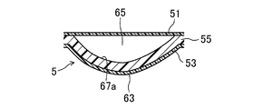
緩衝部材55は、膨出部63,63よりも上方の位置に配置されかつ足幅方向に沿って貫通形成された切り欠き状の変形空間65,65を有している。具体的には、変形空間65,65は、緩衝部材55の上面から下方に向かって凹陥形成されていて、足幅方向に延びている。変形空間65,65は、緩衝部材55の上面のうち膨出部63,63に対応する下壁部67a,67aと上側プレート51との間に位置している。緩衝部材55の上面のうち変形空間65,65が形成されていない部分は、上側プレート51と接着されている。一方、緩衝部材55の下面は、下側プレート53と接着されている。
The cushioning
(支持体の動き)
図4〜図6は、支持体5に外力Fが作用する前後の支持体5の動きを示す。接地時には路面などから受ける反発力などの外力Fがアウトソール33,33…を介して下側プレート53に作用する。このとき、膨出部63,63は上方に向かって変形する。また、緩衝部材55は、下側プレート53と接しているので、膨出部63,63の変形にともなって下壁部67a,67aが上方に変形する。
(Movement of support)
4 to 6 show the movement of the
接地の直後では、支持体5は、変形空間65,65が開いている状態である。すなわち、緩衝部材55の下壁部67a,67aの上部には変形空間65,65が位置している。このため、図5に示すように、緩衝部材55は、下壁部67a,67aが上側プレート51に近付いて変形空間65,65を閉じるように、変形空間65,65内で変形する。このように、変形空間65,65が開いているときには、膨出部63,63は、変形空間65,65に向かって変形することが許容される。支持体5に作用する外力Fが所定値未満のときは、その後、支持体5に作用する外力Fが小さくなるにともなって、膨出部63,63が弾性復元する。
Immediately after the ground contact, the
一方、支持体5に作用する外力Fが所定値以上のときは、下壁部67a,67aの少なくとも一部と上側プレート51とが当接することで変形空間65,65が閉じられて、さらに、膨出部63,63は上方に向かって変形する。図6に示すように、このとき、緩衝部材55は、上側プレート51と膨出部63,63とに挟まれて圧縮変形する。このように、変形空間65,65が閉じているときには、膨出部63,63が上方に向かって変形しかつ緩衝部材55が圧縮変形する。そして、支持体5に作用する外力Fが小さくなるにともなって、膨出部63,63が弾性復元する。
On the other hand, when the external force F acting on the
(第1実施形態の作用効果)
以上のように、支持体5は、変形空間65,65が開いているときに膨出部63,63が変形空間65,65に向かって変形することを許容するように構成されている。これにより、例えば接地時およびその直後では、変形空間65,65が開いた状態となり、緩衝部材55が圧縮変形せずに下側プレート53の膨出部63,63が変形空間65,65に向かって弾性変形するようになる。すなわち、接地時およびその直後では、下側プレート53の膨出部63,63が弾性変形することで優れたクッション性が発揮される。これに対し、接地後も継続してソール構造1に大きな外力Fが作用しているときには、下側プレート53の膨出部63,63の弾性変形により変形空間65,65が閉じるように変位する。そして、変形空間65,65が閉じた状態でソール構造1に対し継続的に大きな外力Fが作用すると、下側プレート53の膨出部63,63が上方に向かって弾性変形しかつ緩衝部材55が圧縮変形する。その結果、膨出部63,63の弾性変形および緩衝部材55の圧縮変形によるクッション性が発揮されるようになる。このとき、膨出部63,63の弾性変形量は、緩衝部材55の圧縮変形により抑えられる。しかし、ソール構造は、上記外力Fのエネルギーが緩衝部材55に吸収および蓄積されてクッション性が発揮されるようになる。このように、接地時およびその後の時間経過に伴いソール構造1に作用する外力Fの大きさに応じてソール構造1のクッション性が段階的に変化する。したがって、第1の形態では、特に接地の状況に応じてクッション性を段階的に変化させることができる。
(Operation and effect of the first embodiment)
As described above, the
さらに、変形空間65,65は、貫通形成されているので、下壁部67a,67aが変形しやすくなる。このため、膨出部63,63および下壁部67a,67aが弾性変形し易くなり接地の直後のクッション性をさらに向上させることができる。
Further, since the
また、支持体5は、着用者の踵部を支持する踵部領域13に配置され、緩衝部材55は、踵部領域13の外周縁に配置されている。ソール構造1のうち踵部領域13の外周縁が接地時に作用する外力Fが大きい領域である。このため、接地時に作用する外力Fが大きい領域に緩衝部材55を配置することができる。
Further, the
また、上側プレート51は、足幅方向両端部に形成されかつ上方に向かって延びる巻き上げ部59を有している。このため、着用者の足が足幅方向に移動することを抑制することができる。したがって、着用者が感じるホールド感を高めることができる。
Further, the
さらに、膨出部63,63は、複数形成され、下側プレート53は、複数の膨出部63,63により波形に形成されている。このため、ソール構造1のクッション性をさらに向上させることができる。
Further, a plurality of bulging
(第1実施形態の参考例)
図7に示すように、上記第1実施形態に係るソール構造1の参考例として、変形空間65,65は、緩衝部材55の下面から上方に向かって凹陥形成されていて、足幅方向に延びている形態としてもよい。
( Reference example of the first embodiment)
As shown in FIG. 7, as a reference example of the
具体的に、変形空間65,65は、緩衝部材55の下面のうち膨出部63,63に対応する上壁部68a,68aと下側プレート53との間に位置している。緩衝部材55の下面のうち変形空間65,65が形成されていない部分は、下側プレート53と接着されている。一方、緩衝部材55の上面は、上側プレート51と接着されている。
Specifically, the
この参考例において、接地の直後では、緩衝部材55は、膨出部63,63が上壁部68a,68aに近付いて変形空間65,65を閉じるように、変形空間65,65内で変形する。このように、変形空間65,65が開いているときには、膨出部63,63は、変形空間65,65により上方に向かって変形することを許容される。
In this reference example , immediately after grounding, the
一方、支持体5に作用する外力Fが所定値以上のときは、膨出部63,63の少なくとも一部と緩衝部材55の上壁部68a,68aとが当接することで変形空間65,65が閉じられて、さらに、膨出部63,63は上方に向かって変形する。このとき、緩衝部材55は、上側プレート51と膨出部63,63とに挟まれて圧縮変形する。このように、変形空間65,65が閉じているときには、膨出部63,63が上方に向かって変形しかつ緩衝部材55が圧縮変形する。
On the other hand, when the external force F acting on the
(第1実施形態の変形例1)
図8に示すように、上記第1実施形態に係るソール構造1の変形例1として、変形空間65,65を、緩衝部材55を貫通するように中空状に形成されている形態としてもよい。
(
As shown in FIG. 8, as a modified example 1 of the
具体的に、変形空間65,65は、緩衝部材55のうち膨出部63,63に対応する位置に形成されている。変形空間65,65は、緩衝部材55の内周面のうち下側の部分を構成する下壁部67b,67bと、緩衝部材55の内周面のうち上側の部分を構成する上壁部68b,68bとの間に位置している。緩衝部材55の下面は、下側プレート53と接着されている。また、緩衝部材55の上面は、上側プレート51と接着されている。
Specifically, the
本変形例において、接地の直後では、緩衝部材55は、膨出部63,63の上方への弾性変形により、下壁部67b,67bが上壁部68b,68bに近付いて変形空間65,65を閉じるように、変形空間65,65内で変形する。このように、変形空間65,65が開いているときには、膨出部63,63は、変形空間65,65により上方に向かって変形することを許容される。
In the present modification, immediately after the ground contact, the cushioning
一方、支持体5に作用する外力Fが所定値以上のときは、下壁部67b,67bの少なくとも一部と上壁部68b,68bが当接することで変形空間65,65が閉じられて、さらに、膨出部63,63は上方に向かって変形する。このとき、緩衝部材55は、上側プレート51と膨出部63,63とに挟まれて圧縮変形する。このように、変形空間65,65が閉じているときには、膨出部63,63が上方に向かって変形しかつ緩衝部材55が圧縮変形する。
On the other hand, when the external force F acting on the
(第1実施形態の変形例2)
図9に示すように、上記第1実施形態に係るソール構造1の変形例2として、緩衝部材55,55…が前後方向に分断して複数設けられている形態としてもよい。
(Modification 2 of the first embodiment)
As shown in FIG. 9, as a second modification of the
[第2実施形態]
図10および図11は、本発明の第2実施形態に係るソール構造1を示す。この実施形態では、第1実施形態と比較して、支持体5の構造が一部異なっている。なお、この実施形態に係るソール構造1の他の構成は、第1実施形態に係るソール構造1の構成と同様である。このため、以下の説明では、図1〜図6と同じ部分について同じ符号を付し、その詳細な説明を省略する。
[Second Embodiment]
10 and 11 show a
本実施形態の下側プレート53は、足幅方向両端部に、前後方向に延びかつ底部が下方に向かって突出する膨出部63,63を有している。緩衝部材55の変形空間65,65は、緩衝部材55の上面から下方に向かって凹陥形成されていて、前後方向に延びている。
The
このように、第2実施形態のソール構造1では、膨出部63,63および変形空間65,65が前後方向に延びている。このため、足幅方向への接地の際に支持体5が変形し易くなる。したがって、第2実施形態のソール構造1は、足幅方向への動きが多いインドア競技用シューズのソール構造に適している。
As described above, in the
[第3実施形態]
図12は、本発明の第3実施形態に係るソール構造1を示す。この実施形態では、第1実施形態と比較して、支持体5の構造が一部異なっている。
[Third Embodiment]
FIG. 12 shows a
第3の実施形態に係るソール構造1は、例えばサッカー、ラグビー、アメリカンフットボール、野球などのスポーツに用いられるクリーツシューズに適したものである。
The
第3の実施形態では、ソール本体3が支持体5の一部を兼ねるように構成されている。具体的には、上側プレート51は、ミッドソール31を形成している。また、下側プレート53は、アウトソール33,33…を形成している。下側プレート53の下面には、複数のスタッド71,71…が設けられている。このようにして、ソール本体3に支持体5が設けられている。また、第3の実施形態では膨出部63は、1つ設けられている。
In the third embodiment, the
以上、本発明についての実施形態を説明したが、本発明は上述の実施形態のみに限定されず、発明の範囲内で種々の変更が可能である。 Although the embodiments of the present invention have been described above, the present invention is not limited to the above-described embodiments, and various modifications can be made within the scope of the invention.
本発明は、例えばウォーキングシューズやランニングシューズ、インドア競技用シューズ、または土や芝生の上で行われる球技用シューズなどに適用されるシューズとして産業上の利用が可能である。 INDUSTRIAL APPLICABILITY The present invention can be industrially used as shoes applied to, for example, walking shoes, running shoes, indoor competition shoes, or shoes for ball games performed on soil or grass.
1 ソール構造
3 ソール本体
5 支持体
13 踵部領域
51 上側プレート
53 下側プレート
55 緩衝部材
59 巻き上げ部
63 膨出部
65 変形空間
1
Claims (3)
前記ソール本体において着用者の踵部を支持する踵部領域には、支持体が設けられており、
前記支持体は、
着用者の足を支持する上側プレートと、
前記上側プレートよりも下方の位置に配置された下側プレートと、
前記上側プレートと前記下側プレートとの間に配置されかつ該上側プレートおよび該下側プレートよりもヤング率が低い弾性変形可能な緩衝部材と、を有し、
前記下側プレートは、各々の底部が下方に向かって突出するように形成された弾性変形可能な複数の膨出部を含み、かつ、前記複数の膨出部により凹凸が前後方向に繰り返される波形状を有しており、
前記緩衝部材は、前記踵部領域において少なくとも着用者の足の内甲側および外甲側の双方に対応する外周縁に配置され、かつ、前記複数の膨出部の前後方向全域を上方から覆うように構成されており、
前記緩衝部材には、前記複数の膨出部の各々よりも上方の位置に配置されかつ前記ソール本体の厚さ方向に直交する方向に沿って貫通形成された中空状または切り欠き状の複数の変形空間が設けられており、
前記支持体は、前記変形空間が開いているときに該変形空間により前記膨出部が該変形空間に向かって弾性変形することを許容する一方、該変形空間が閉じているときに該膨出部が上方に向かって弾性変形しかつ前記緩衝部材が圧縮変形するように構成されている、ソール構造。 A sole structure for shoes including a sole body,
Wherein the heel region for supporting the heel portion of Oite wearer sole body, is provided a support,
The support is
An upper plate that supports the wearer's foot,
A lower plate arranged at a position lower than the upper plate,
An elastically deformable cushioning member that is arranged between the upper plate and the lower plate and has a Young's modulus lower than those of the upper plate and the lower plate;
The lower plate includes a plurality of elastically deformable bulging portions formed so that each bottom portion thereof projects downward, and a wave in which unevenness is repeated in the front-back direction by the plurality of bulging portions. Has a shape,
The cushioning member is disposed at the outer peripheral edge corresponding to both the inner side and the outer side of the wearer's foot in the heel region, and covers the entire front and rear direction of the plurality of bulging portions from above. Is configured as
The cushioning member has a plurality of hollow or notched portions which are arranged at a position higher than each of the plurality of bulging portions and which are formed so as to penetrate along the direction orthogonal to the thickness direction of the sole body . Deformation space is provided,
The support body allows the bulging portion to elastically deform toward the deformation space by the deformation space when the deformation space is open, and the bulge when the deformation space is closed. A sole structure in which a portion is elastically deformed upward and the cushioning member is compressively deformed.
前記上側プレートは、足幅方向両端部に形成されかつ上方に向かって延びる巻き上げ部を有する、ソール構造。 The sole structure according to claim 1 ,
A sole structure in which the upper plate has winding portions formed at both ends in the width direction of the foot and extending upward.
Priority Applications (3)
| Application Number | Priority Date | Filing Date | Title |
|---|---|---|---|
| JP2018052913A JP6722709B2 (en) | 2018-03-20 | 2018-03-20 | Sole structure and shoes |
| DE102019105731.0A DE102019105731A1 (en) | 2018-03-20 | 2019-03-07 | Sole structure and shoe with such a sole structure |
| US16/357,386 US10932518B2 (en) | 2018-03-20 | 2019-03-19 | Sole structure and shoe including same |
Applications Claiming Priority (1)
| Application Number | Priority Date | Filing Date | Title |
|---|---|---|---|
| JP2018052913A JP6722709B2 (en) | 2018-03-20 | 2018-03-20 | Sole structure and shoes |
Publications (2)
| Publication Number | Publication Date |
|---|---|
| JP2019162357A JP2019162357A (en) | 2019-09-26 |
| JP6722709B2 true JP6722709B2 (en) | 2020-07-15 |
Family
ID=67847977
Family Applications (1)
| Application Number | Title | Priority Date | Filing Date |
|---|---|---|---|
| JP2018052913A Active JP6722709B2 (en) | 2018-03-20 | 2018-03-20 | Sole structure and shoes |
Country Status (3)
| Country | Link |
|---|---|
| US (1) | US10932518B2 (en) |
| JP (1) | JP6722709B2 (en) |
| DE (1) | DE102019105731A1 (en) |
Families Citing this family (4)
| Publication number | Priority date | Publication date | Assignee | Title |
|---|---|---|---|---|
| WO2022130538A1 (en) | 2020-12-16 | 2022-06-23 | 株式会社アシックス | Sole structure and shoe |
| US12035778B2 (en) * | 2021-03-15 | 2024-07-16 | Nike, Inc. | Article of footwear |
| CN113498910A (en) * | 2021-07-29 | 2021-10-15 | 安踏(中国)有限公司 | Sport shoe and insole system thereof |
| CN118235912A (en) * | 2022-12-23 | 2024-06-25 | 索克尼公司 | Article of footwear with sole plate |
Family Cites Families (15)
| Publication number | Priority date | Publication date | Assignee | Title |
|---|---|---|---|---|
| JP3014660U (en) | 1995-02-10 | 1995-08-15 | 古谷産業株式会社 | Sports shoes |
| US7730635B2 (en) * | 2004-09-27 | 2010-06-08 | Nike, Inc. | Impact-attenuation members and products containing such members |
| US7779558B2 (en) * | 2004-09-30 | 2010-08-24 | Asics Corporation | Shock absorbing device for shoe sole |
| US7877899B2 (en) | 2004-09-30 | 2011-02-01 | Asics Corporation | Shock absorbing device for shoe sole in rear foot part |
| BRPI0519565B1 (en) * | 2004-12-27 | 2017-03-28 | Mizuno Kk | sole structure for a shoe |
| WO2006129392A1 (en) * | 2005-05-30 | 2006-12-07 | Mizuno Corporation | Sole structure body for shoes |
| US20070113425A1 (en) * | 2005-11-23 | 2007-05-24 | Gary Wakley | Cushioning system for footwear |
| JP4153002B2 (en) * | 2006-08-30 | 2008-09-17 | 美津濃株式会社 | Middle foot structure of shoe sole assembly |
| US8365445B2 (en) * | 2007-05-22 | 2013-02-05 | K-Swiss, Inc. | Shoe outsole having semicircular protrusions |
| WO2008156164A1 (en) | 2007-06-21 | 2008-12-24 | Juya Yamaguchi | Insole for footgear |
| US20090126224A1 (en) * | 2007-11-19 | 2009-05-21 | Greene Pamela S | Differential-stiffness impact-attenuation members and products including them |
| JP4874349B2 (en) * | 2008-03-31 | 2012-02-15 | 美津濃株式会社 | Sole sole structure |
| US20110239489A1 (en) | 2010-04-02 | 2011-10-06 | Mizuno Corporation | Sole Structure for a Shoe |
| US9125453B2 (en) * | 2010-05-28 | 2015-09-08 | K-Swiss Inc. | Shoe outsole having tubes |
| JP5827051B2 (en) | 2011-07-09 | 2015-12-02 | 美津濃株式会社 | Sole sole structure |
-
2018
- 2018-03-20 JP JP2018052913A patent/JP6722709B2/en active Active
-
2019
- 2019-03-07 DE DE102019105731.0A patent/DE102019105731A1/en active Pending
- 2019-03-19 US US16/357,386 patent/US10932518B2/en active Active
Also Published As
| Publication number | Publication date |
|---|---|
| US20190289959A1 (en) | 2019-09-26 |
| US10932518B2 (en) | 2021-03-02 |
| DE102019105731A1 (en) | 2019-09-26 |
| JP2019162357A (en) | 2019-09-26 |
Similar Documents
| Publication | Publication Date | Title |
|---|---|---|
| KR101752984B1 (en) | Sole structures and articles of footwear having plate moderated fluid-filled bladders and/or foam type impact force attenuation members | |
| JP6076481B2 (en) | Sole structure and footwear product with plate relaxation fluid filled bladder and / or foam type impact force damping member | |
| JP6294909B2 (en) | Sole structure for shoes and shoes using the same | |
| US9125453B2 (en) | Shoe outsole having tubes | |
| JP6473201B1 (en) | shoes | |
| JP6722709B2 (en) | Sole structure and shoes | |
| US5311674A (en) | Energy return system in an athletic shoe | |
| JP4020953B2 (en) | Sole sole structure | |
| US7444767B2 (en) | Article of footwear with midsole having higher density peripheral portion | |
| JP6688326B2 (en) | Sole structure and shoes using it | |
| WO2016208061A1 (en) | Shoe having sole having divided forefoot section | |
| WO2016208062A1 (en) | Shoe having sole having divided hind foot section | |
| US20030000108A1 (en) | Midsole structure of athletic shoe | |
| WO2006129392A1 (en) | Sole structure body for shoes | |
| JP7002386B2 (en) | Sole structure and shoes using it | |
| JPWO2008047538A1 (en) | The structure of the forefoot of the shoe sole | |
| JP2001008704A (en) | Midsole of sporting shoes | |
| KR100825437B1 (en) | Sole structure of professional shoes for masai walking with waist shape shank and soft sensing body | |
| WO2017163741A1 (en) | Shoe sole structure and shoe using same | |
| JP2000083705A (en) | Shoe sole structure | |
| KR100807365B1 (en) | Sole structure of professional shoes for Masai walking with side pad sensor | |
| JP2004242692A (en) | Sole assembly of sports shoe | |
| JP3868440B2 (en) | Spike shoes | |
| JP7115860B2 (en) | Shoe sole shock absorbing member and shoe provided with the same | |
| JPS627123Y2 (en) |
Legal Events
| Date | Code | Title | Description |
|---|---|---|---|
| A621 | Written request for application examination |
Free format text: JAPANESE INTERMEDIATE CODE: A621 Effective date: 20181113 |
|
| A131 | Notification of reasons for refusal |
Free format text: JAPANESE INTERMEDIATE CODE: A131 Effective date: 20200107 |
|
| A521 | Request for written amendment filed |
Free format text: JAPANESE INTERMEDIATE CODE: A523 Effective date: 20200304 |
|
| TRDD | Decision of grant or rejection written | ||
| A01 | Written decision to grant a patent or to grant a registration (utility model) |
Free format text: JAPANESE INTERMEDIATE CODE: A01 Effective date: 20200526 |
|
| A61 | First payment of annual fees (during grant procedure) |
Free format text: JAPANESE INTERMEDIATE CODE: A61 Effective date: 20200622 |
|
| R150 | Certificate of patent or registration of utility model |
Ref document number: 6722709 Country of ref document: JP Free format text: JAPANESE INTERMEDIATE CODE: R150 |
|
| R250 | Receipt of annual fees |
Free format text: JAPANESE INTERMEDIATE CODE: R250 |