JP6706697B2 - Electric power steering device and rack assist type steering device - Google Patents
Electric power steering device and rack assist type steering device Download PDFInfo
- Publication number
- JP6706697B2 JP6706697B2 JP2018566033A JP2018566033A JP6706697B2 JP 6706697 B2 JP6706697 B2 JP 6706697B2 JP 2018566033 A JP2018566033 A JP 2018566033A JP 2018566033 A JP2018566033 A JP 2018566033A JP 6706697 B2 JP6706697 B2 JP 6706697B2
- Authority
- JP
- Japan
- Prior art keywords
- control unit
- electronic control
- electric power
- winding
- power steering
- Prior art date
- Legal status (The legal status is an assumption and is not a legal conclusion. Google has not performed a legal analysis and makes no representation as to the accuracy of the status listed.)
- Expired - Fee Related
Links
- 238000004804 winding Methods 0.000 claims description 121
- 230000005484 gravity Effects 0.000 claims description 7
- XLYOFNOQVPJJNP-UHFFFAOYSA-N water Substances O XLYOFNOQVPJJNP-UHFFFAOYSA-N 0.000 claims description 4
- WABPQHHGFIMREM-UHFFFAOYSA-N lead(0) Chemical group [Pb] WABPQHHGFIMREM-UHFFFAOYSA-N 0.000 description 58
- 230000007935 neutral effect Effects 0.000 description 40
- 238000006243 chemical reaction Methods 0.000 description 19
- 239000003638 chemical reducing agent Substances 0.000 description 9
- 230000000694 effects Effects 0.000 description 6
- 230000002093 peripheral effect Effects 0.000 description 6
- 239000011248 coating agent Substances 0.000 description 5
- 238000000576 coating method Methods 0.000 description 5
- 239000002184 metal Substances 0.000 description 4
- 239000000853 adhesive Substances 0.000 description 3
- 230000001070 adhesive effect Effects 0.000 description 3
- 238000001514 detection method Methods 0.000 description 3
- 229920003002 synthetic resin Polymers 0.000 description 3
- 239000000057 synthetic resin Substances 0.000 description 3
- 230000003111 delayed effect Effects 0.000 description 2
- 230000008595 infiltration Effects 0.000 description 2
- 238000001764 infiltration Methods 0.000 description 2
- 238000000034 method Methods 0.000 description 2
- 238000012986 modification Methods 0.000 description 2
- 230000004048 modification Effects 0.000 description 2
- 230000036316 preload Effects 0.000 description 2
- 238000003466 welding Methods 0.000 description 2
- 230000006866 deterioration Effects 0.000 description 1
- 238000010586 diagram Methods 0.000 description 1
- 230000001771 impaired effect Effects 0.000 description 1
- JEIPFZHSYJVQDO-UHFFFAOYSA-N iron(III) oxide Inorganic materials O=[Fe]O[Fe]=O JEIPFZHSYJVQDO-UHFFFAOYSA-N 0.000 description 1
- 230000035515 penetration Effects 0.000 description 1
- 239000004576 sand Substances 0.000 description 1
- 238000007789 sealing Methods 0.000 description 1
- 239000003566 sealing material Substances 0.000 description 1
- 230000035939 shock Effects 0.000 description 1
- 229910000679 solder Inorganic materials 0.000 description 1
Images


Classifications
-
- B—PERFORMING OPERATIONS; TRANSPORTING
- B62—LAND VEHICLES FOR TRAVELLING OTHERWISE THAN ON RAILS
- B62D—MOTOR VEHICLES; TRAILERS
- B62D5/00—Power-assisted or power-driven steering
- B62D5/04—Power-assisted or power-driven steering electrical, e.g. using an electric servo-motor connected to, or forming part of, the steering gear
- B62D5/0403—Power-assisted or power-driven steering electrical, e.g. using an electric servo-motor connected to, or forming part of, the steering gear characterised by constructional features, e.g. common housing for motor and gear box
- B62D5/0406—Power-assisted or power-driven steering electrical, e.g. using an electric servo-motor connected to, or forming part of, the steering gear characterised by constructional features, e.g. common housing for motor and gear box including housing for electronic control unit
-
- B—PERFORMING OPERATIONS; TRANSPORTING
- B62—LAND VEHICLES FOR TRAVELLING OTHERWISE THAN ON RAILS
- B62D—MOTOR VEHICLES; TRAILERS
- B62D5/00—Power-assisted or power-driven steering
- B62D5/04—Power-assisted or power-driven steering electrical, e.g. using an electric servo-motor connected to, or forming part of, the steering gear
- B62D5/0457—Power-assisted or power-driven steering electrical, e.g. using an electric servo-motor connected to, or forming part of, the steering gear characterised by control features of the drive means as such
- B62D5/046—Controlling the motor
-
- B—PERFORMING OPERATIONS; TRANSPORTING
- B62—LAND VEHICLES FOR TRAVELLING OTHERWISE THAN ON RAILS
- B62D—MOTOR VEHICLES; TRAILERS
- B62D5/00—Power-assisted or power-driven steering
- B62D5/04—Power-assisted or power-driven steering electrical, e.g. using an electric servo-motor connected to, or forming part of, the steering gear
- B62D5/0457—Power-assisted or power-driven steering electrical, e.g. using an electric servo-motor connected to, or forming part of, the steering gear characterised by control features of the drive means as such
- B62D5/0475—Controlling other elements
-
- B—PERFORMING OPERATIONS; TRANSPORTING
- B62—LAND VEHICLES FOR TRAVELLING OTHERWISE THAN ON RAILS
- B62D—MOTOR VEHICLES; TRAILERS
- B62D5/00—Power-assisted or power-driven steering
- B62D5/04—Power-assisted or power-driven steering electrical, e.g. using an electric servo-motor connected to, or forming part of, the steering gear
- B62D5/0457—Power-assisted or power-driven steering electrical, e.g. using an electric servo-motor connected to, or forming part of, the steering gear characterised by control features of the drive means as such
- B62D5/0481—Power-assisted or power-driven steering electrical, e.g. using an electric servo-motor connected to, or forming part of, the steering gear characterised by control features of the drive means as such monitoring the steering system, e.g. failures
- B62D5/0484—Power-assisted or power-driven steering electrical, e.g. using an electric servo-motor connected to, or forming part of, the steering gear characterised by control features of the drive means as such monitoring the steering system, e.g. failures for reaction to failures, e.g. limp home
-
- B—PERFORMING OPERATIONS; TRANSPORTING
- B62—LAND VEHICLES FOR TRAVELLING OTHERWISE THAN ON RAILS
- B62D—MOTOR VEHICLES; TRAILERS
- B62D5/00—Power-assisted or power-driven steering
- B62D5/04—Power-assisted or power-driven steering electrical, e.g. using an electric servo-motor connected to, or forming part of, the steering gear
- B62D5/0457—Power-assisted or power-driven steering electrical, e.g. using an electric servo-motor connected to, or forming part of, the steering gear characterised by control features of the drive means as such
- B62D5/0481—Power-assisted or power-driven steering electrical, e.g. using an electric servo-motor connected to, or forming part of, the steering gear characterised by control features of the drive means as such monitoring the steering system, e.g. failures
- B62D5/0487—Power-assisted or power-driven steering electrical, e.g. using an electric servo-motor connected to, or forming part of, the steering gear characterised by control features of the drive means as such monitoring the steering system, e.g. failures detecting motor faults
-
- H—ELECTRICITY
- H02—GENERATION; CONVERSION OR DISTRIBUTION OF ELECTRIC POWER
- H02K—DYNAMO-ELECTRIC MACHINES
- H02K11/00—Structural association of dynamo-electric machines with electric components or with devices for shielding, monitoring or protection
- H02K11/30—Structural association with control circuits or drive circuits
-
- H—ELECTRICITY
- H02—GENERATION; CONVERSION OR DISTRIBUTION OF ELECTRIC POWER
- H02K—DYNAMO-ELECTRIC MACHINES
- H02K3/00—Details of windings
- H02K3/04—Windings characterised by the conductor shape, form or construction, e.g. with bar conductors
- H02K3/18—Windings for salient poles
-
- H—ELECTRICITY
- H02—GENERATION; CONVERSION OR DISTRIBUTION OF ELECTRIC POWER
- H02K—DYNAMO-ELECTRIC MACHINES
- H02K5/00—Casings; Enclosures; Supports
- H02K5/04—Casings or enclosures characterised by the shape, form or construction thereof
- H02K5/10—Casings or enclosures characterised by the shape, form or construction thereof with arrangements for protection from ingress, e.g. water or fingers
Landscapes
- Engineering & Computer Science (AREA)
- Chemical & Material Sciences (AREA)
- Combustion & Propulsion (AREA)
- Transportation (AREA)
- Mechanical Engineering (AREA)
- Power Engineering (AREA)
- Power Steering Mechanism (AREA)
- Motor Or Generator Frames (AREA)
- Windings For Motors And Generators (AREA)
Description
本発明は電動パワーステアリング装置に係り、特に電動モータが2系統に構成された電動パワーステアリング装置及びこれを使用したラックアシスト式操舵装置に関するものである。 The present invention relates to an electric power steering device, and more particularly to an electric power steering device having an electric motor in two systems and a rack assist type steering device using the electric power steering device.
自動車の電動パワーステアリング装置においては、運転者がステアリングホイールを操作することにより回動するステアリングシャフトの回動方向と回動力とを検出し、この検出値に基づいてステアリングシャフトの回動方向と同じ方向へ回動するように電動モータを駆動して、操舵補助力を発生させるように構成されている。また、この電動モータを制御するため、電子制御部がパワーステアリング装置に設けられている。 In an electric power steering apparatus for an automobile, a driver detects a turning direction and a turning force of a steering shaft that is turned by operating a steering wheel, and based on the detected values, the turning direction of the steering shaft is the same. The electric motor is driven so as to rotate in the direction, and a steering assist force is generated. An electronic control unit is provided in the power steering device to control the electric motor.
そして、この種の電動パワーステアリング装置においては、ステアリング操作を補助するために三相交流電動モータが使用されており、この三相交流電動モータを制御、駆動するためにインバータ回路からなる電力変換回路が用いられている。ところで、電動モータが故障すると操舵アシスト力を発生することができなくなり、運転者の操舵が困難になる恐れが大きい。このため、最近では電動モータを構成するステータに巻回される巻線、及びこの巻線に与える電力を制御する電力変換回路を2系統に構成し、一方の系統に故障が発生しても、他方の系統で操舵アシスト力を発生して運転者の操舵を支援する電動パワーステアリング装置が提案されている。 In this type of electric power steering apparatus, a three-phase AC electric motor is used to assist steering operation, and a power conversion circuit including an inverter circuit is used to control and drive the three-phase AC electric motor. Is used. By the way, if the electric motor fails, the steering assist force cannot be generated, and there is a high possibility that the driver's steering becomes difficult. For this reason, recently, a winding wound around a stator that constitutes an electric motor and a power conversion circuit that controls electric power applied to the winding are configured in two systems, and even if a failure occurs in one system, There has been proposed an electric power steering device that generates a steering assist force in the other system to assist the driver in steering.
このような2系統の電動モータを備える電動パワーステアリング装置は、数多くの文献にあるようによく知られているが、例えば、特開2007-331639号公報(特許文献1)には、次のような2系統の電動モータを使用した電動パワーステアリング装置が示されている。特許文献1には、ステータに巻回される巻線を2系統巻線に構成し、ステータに巻回される一方の系統の巻線を2分割して180°の対向位置に配置すると共に、他方の系統の巻線も2分割して、一方の系統の巻線位置と90°回転した、180°の対向位置に配置した電動パワーステアリング装置が示されている。
An electric power steering apparatus including such an electric motor of two systems is well known as described in many documents. For example, Japanese Patent Laid-Open No. 2007-331639 (Patent Document 1) discloses the following. An electric power steering apparatus using two electric motors is shown. In
ところで、電動パワーステアリング装置を使用したラックアシスト式の操舵装置においては、ラックケースとラック軸との間はゴムブーツによって覆われている。そして、このゴムブーツは、走行中に飛び跳ねた小石や、道路上の障害物によって往々にして破損することがある。そして、この状態で雨中を走行している時や、水溜り道路を走行している時に、ゴムブーツの破損個所から水分(以下、代表して雨水等と表記する)が浸入することが想定される。この場合、ラックアシスト式の操舵装置においては、電動パワーステアリング装置の電動モータがラック軸やゴムブーツより低い位置、いわゆる、地側に配置されていることが多く、ゴムブーツに浸入した雨水等が、更に電動モータのハウジング内部に浸入することになる。 By the way, in a rack assist type steering device using an electric power steering device, a rubber boot covers between the rack case and the rack shaft. Then, the rubber boots are often damaged by pebbles that jumped up while running or obstacles on the road. Then, when running in the rain in this state or when running on a water pool road, it is assumed that water (hereinafter, typically referred to as rainwater etc.) intrudes from the damaged portion of the rubber boot. .. In this case, in the rack assist type steering device, the electric motor of the electric power steering device is often arranged at a position lower than the rack shaft and the rubber boot, that is, on the ground side, and rainwater or the like that has infiltrated the rubber boot is further reduced. It will penetrate into the housing of the electric motor.
そして、特許文献1においては、2系統の巻線は4分割してステータに巻かれているため、電動モータのハウジング内部に雨水等が浸入した場合、2系統の双方の巻線が雨水に浸漬するため、巻線の被覆が損傷していたりすると巻線の電気的な短絡現象を生じる恐れがあった。尚、ステータの巻線を2分割した構成の2系統巻線でも、巻線の巻回位置によって上述の課題を生じる恐れがある。そして、短絡現象によって電動モータが故障すると操舵アシスト力を発生することができなくなり、運転者の操舵が困難になる恐れが大きくなる。
In
本発明の目的は、ゴムブーツの破損によって電動モータのハウジング内へ雨水等が浸入して電気的な短絡現象を発生する環境になっても、できるだけ操舵アシスト機能を継続することができる新規な電動パワーステアリング装置及びこれを使用した操舵装置を提供することにある。 An object of the present invention is to provide a novel electric power that can continue the steering assist function as much as possible even in an environment in which rainwater or the like enters the housing of the electric motor due to damage to the rubber boot to cause an electrical short circuit phenomenon. A steering device and a steering device using the same are provided.
本発明の特徴は、巻線が巻回されるステータを重力方向に対して上下に2領域に分割し、ステータの上側ステータ領域に一方の系統の巻線を巻回すると共に、ステータの下側ステータ領域に他方の系統の巻線を巻回し、更に、一方の系統の巻線の電力を一方の系統の電子制御手段によって制御すると共に、他方の系統の巻線の電力を他方の系統の電子制御手段によって制御する、ところにある。 The feature of the present invention is that the stator around which the winding is wound is divided into two regions up and down with respect to the direction of gravity, the winding of one system is wound around the upper stator region of the stator, and The winding of the other system is wound around the stator area, and the electric power of the winding of the one system is controlled by the electronic control means of the one system, and the power of the winding of the other system is controlled by the electronic system of the other system. It is in the place where it is controlled by the control means.
本発明によれば、ゴムブーツの破損によって電動モータのハウジング内へ雨水等が浸入しても、少なくとも上側に巻回された巻線は電気的な短絡現象の発生を抑制されて、操舵アシストを継続することができるようになる。 According to the present invention, even if rainwater or the like enters the housing of the electric motor due to damage to the rubber boot, at least the winding wound on the upper side suppresses the occurrence of an electrical short circuit and continues the steering assist. You will be able to.
以下、本発明の実施形態について図面を用いて詳細に説明するが、本発明は以下の実施形態に限定されることなく、本発明の技術的な概念の中で種々の変形例や応用例をもその範囲に含むものである。 Hereinafter, embodiments of the present invention will be described in detail with reference to the drawings, but the present invention is not limited to the following embodiments, and various modifications and applications within the technical concept of the present invention. Is also included in the range.
図1は、ラックアシスト式の操舵装置(以下、電動パワーステアリングシステムと表記する)の構成を示している。電動パワーステアリングシステムは、運転者がステアリングホイール42の操作を行った場合、その操舵力をラックケースに設けられた電動モータによりアシストするもので、モータ軸の延長上には減速機を介してラック軸44を直線運動に変換する構造となっている。ステアリングホイール42を運転者が操作すると、ステアリングシャフト41の回転をトルクセンサ(図示せず)によって検出し、機電一体型の電動パワーステアリング装置47に対して検出信号を伝送する。
FIG. 1 shows the configuration of a rack assist type steering device (hereinafter referred to as an electric power steering system). The electric power steering system assists the steering force of a
その検出信号を基に制御装置は電動モータに駆動電流を通電し、これによって電動モータが回転される。ラック軸44とモータ軸の間には減速機が配置されており、この減速機はモータ軸の回転力をラック軸44を左右に動かす直線運動に変換するものである。この動作により、タイヤ45が左右に旋回運動を行うものである。図1は、電動パワーステアリングシステムの全体構造を車両の前方から見た状態を示しており、ステアリングホイール42の上面が「天側」を示し、電動パワーステアリング装置47の下面が「地側」となり、電動パワーステアリング装置47がラック軸44よりも路面側に配置された状態を示している。
Based on the detection signal, the control device supplies a drive current to the electric motor, which causes the electric motor to rotate. A speed reducer is arranged between the
この場合、ラック軸44とラックケース43の接続部に配置されるゴムブーツ48が破損した場合には、ゴムブーツ48内に雨水等が浸入するようになる。浸入した雨水等は最も低い部分となる減速機ケース部46に溜まり、減速機の錆びや、雨水に混じる砂が侵入することにより、減速機の機能を損なう可能性が有る。更に、減速機ケース部46の下部に雨水等が溜まることで、減速機ケース部46の隣に配置される電動パワーステアリング装置47の電動モータのハウジング内部にも雨水等が浸入する。
In this case, when the
このため、電動モータの巻線の被覆が損傷している場合にあっては、電動モータのハウジング内の雨水等によって結線短絡を生じてブレーキトルクが発生し、ラック軸44を左右に動かすアシスト機能が得られず、ステアリングホイール42の切りかえしが重くなる可能性が高くなる。もちろん、巻線の被覆が損傷していなくても結線短絡を生じる恐れがあることはいうまでもない。このため、電動パワーステアリング装置47の内部に雨水等が浸入した場合でも、ラック軸44のアシスト機能をできるだけ継続させる構成が必要である。
Therefore, in the case where the coating of the winding of the electric motor is damaged, a connection short circuit is caused by rainwater in the housing of the electric motor to generate a brake torque, and an assist function for moving the
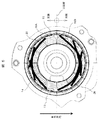
図2には、図1に示した減速機ケース部46のA−A断面を示している。電動パワーステアリング装置47と減速機ケース部46は、締結ボルト40により相互に固定されている。減速機ケース部46の内部には、モータプーリ11、ギアプーリ38が配置され、電動パワーステアリング装置47に取付けられている電動モータのモータプーリ11の回転力を、ベルト39を介してギアプーリ38に伝達している。減速機ケース部46に内蔵された減速機構は、回転/直動変換機構によってラック軸44を左右に動かす直線運動に変換し、この動作によってタイヤ45を左右に旋回させる操舵アシスト機能を実行するものである。このような操舵アシスト機能を与える電動パワーステアリング装置は良く知られている技術である。
FIG. 2 shows an AA cross section of the speed
ここで、車両に対する各部品の搭載レイアウトは、重力方向で見て、減速機ケース部46のステアリングシャフト41の上面は天側であり、電動パワーステアリング装置47の下面は地側となる。このため、ゴムブーツ48が破損し、雨水等がラック軸44の付近に浸入してきた場合、この雨水は、減速機ケース部46の最も低い地側に配置される電動パワーステアリング装置47に組付けられた、モータプーリ11の近辺に溜まりやすい構造となっている。
Here, the mounting layout of each component on the vehicle is such that the upper surface of the
図3は、減速機ケース部46に取付けられる電動パワーステアリング装置47を示しており、電動パワーステアリング装置47は、電動モータ部37と電子制御部30とから構成されている。電動モータ部37はハウジング13とフロントブラケット12から筐体が形成され、内部に電動モータが内蔵されている。電動モータのシャフト先端部分にはモータプーリ11が設けられており、先に述べたように、モータプーリ11の回転力はベルト39を介してギアプーリ38に伝えられるように構成されている。
FIG. 3 shows an electric
モータプーリ11の反対側には、制御基板及びMOSFETを用いた電力変換回路から構成される電子制御装置が内蔵された電子制御部30が配置されており、制御基板及び電力変換回路は、金属製のケース31によって外周側を覆われ保護されている。また、制御基板及び電力変換回路への電源供給を行うためのコネクタ部32がケース31の外側に設けられている。
On the opposite side of the
ここでは図示していないが、電動モータ部37のフロントブラケット12は減速機ケース部46へシール溝23にシール材(図示せず)を用いて防水機能を持たせて固定されている。先に述べたラックケース43とラック軸44の繋ぎ部分に設けられる、防水用のゴムブーツ48は、経年劣化や外部からの機械的な衝撃により破損することが想定される。このため、ゴムブーツ48の破損部分から雨水等が浸入し、この雨水は電動モータ部37のハウジング13内にまで浸入することがある。
Although not shown here, the
上述したように、電動パワーステアリング装置47の車両に対する搭載レイアウトは、図に示すように、重力方向で見て、ハウジング13、ケース31の円形部分の上半分が「天側」となり、下半分が「地側」となるレイアウトとなっている。
As described above, the mounting layout of the electric
図4は図3に示した電動モータ部37の断面を示したものであり、その構成を簡単に説明する。電動モータの中心部にはモータ軸22が配置され、その先端部にはモータプーリ11が配置されている。モータ軸22の中央付近にはロータコア20が2段スキューされた状態で固定されている。ロータコア20の外周部には永久磁石21が取り付けられ、その外周部を磁石カバー(図示せず)で覆っている。
FIG. 4 shows a cross section of the
モータ軸22は、フロントブラケット12に取り付けられたフロントベアリング17と、ハウジング13に取り付けられたリアベアリング18によって支持されている。尚、リアベアリング18は予圧ばね19によってロータコア20側に付勢されている。フロントブラケット12は、ハウジング13に締結ボルト25で固定され、電動モータを密閉している。ただ、フロントブラケット12とモータ軸22の間には、モータ軸22を回転させるために僅かの隙間が形成され、この隙間を介して雨水等がハウジング13内に浸入してくるものである。
The
ハウジング13の内部には、分割されたステータコア14が溶接、又は非溶接で円環形状に形成されて、圧入、又は焼嵌めで固定されている。そして、ステータコア14にボビン15を取り付け、ボビン15の外周部に上側巻線16A、下側巻線16Bを巻回して固定子を形成する。ここで、上側巻線16A、下側巻線16Bは2系統の巻線として形成されている。
Inside the
つまり、上側巻線16A、下側巻線16Bが巻回されるステータコア14が、モータ軸22の軸線(=分割線)位置で、重力方向に対して直交する平面を境にして上下に、「天側」と「地側」の2領域に分割されている。そして、ステータコア14の上側ステータ領域(分割線の上側)に一方の系統の上側巻線16Aを巻回すると共に、ステータコア14の下側ステータ領域(分割線の下側)に他方の系統の下側巻線16Bを巻回している。また、一方の系統の上側巻線16Aの電力は、一方の系統の電子制御手段によって制御され、他方の系統の下側巻線16Bの電力は、他方の系統の電子制御手段によって、それぞれ個別に制御されるものである。これについては図7で詳細に説明する。
That is, the
したがって、ハウジング13内に雨水等が浸入してきた場合、最初に下側巻線16Bが雨水等に接触し、その後に上側巻線16Aが雨水等に接触することになる。したがって、雨水等による結線短絡現象を生じる危険性は、上側巻線16Aより下側巻線16Bの方が大きくなるが、上側巻線16A、下側巻線16Bの両方が結線短絡する場合に比べて、上側巻線16Aを正常状態に継続している期間を長くできる。このように、操舵アシスト機能の能力は低下するが、その分だけ操舵アシスト機能を長く維持することが可能となる。
Therefore, when rainwater or the like enters the
また、ハウジング13の側面壁13Sには貫通穴(図示せず)が設けられ、ステータコア14に巻回された上側巻線16A、下側巻線16Bの口出し線が、ハウジング13の内部からモータ軸22の長手方向に引き出されている。ハウジング13の内部から引き出された上側巻線16A、下側巻線16Bの口出し線は、モータプーリ11の反対側に配置された電子制御部30の電力変換回路の端子(図示せず)に、溶接又は半田で電気的に接続されている。電子制御部30から電力を上側巻線16A、下側巻線16Bに給電することでロータコア20が回転され、これによってモータプーリ11の回転力がベルト39を介してギアプーリ38に与えられることで、減速機構によってラック軸44を左右に動かす直線運動に変換している。
Further, a through hole (not shown) is provided in the
更に、磁極センサ(図示せず)は、モータ軸22のモータプーリ11側とは反対側の電子制御部30側に取り付けられ、電子制御部30に設けられたGMR素子のような検出素子により、ロータの磁極位置を検出できるようになっている。
Further, a magnetic pole sensor (not shown) is attached to the side of the
尚、図4には詳細に示していないが、電動モータ部37の内部と電子制御部30の内部が繋がる部分は、合成樹脂、又は金属等から作られた防水壁(図6A、図6B参照)が形成されて防水対策を施している。これによって、電動モータ部37のハウジング13の内部に侵入した雨水等は、電子制御部30の内部へ浸入しないので、電子制御部30の電気的な安全性を確保することが可能となる。
Although not shown in detail in FIG. 4, a portion where the inside of the
図5は、上側巻線16A、下側巻線16Bが巻回されたステータコア14がハウジング13に収納された状態を示している。分割されたステータコア14にボビン15を取付け、ボビン15の外周部に夫々の巻線16A、16Bが2連続巻線され、分割されたステータコア14が溶接、又は非溶接で円環形状を保持しながら、圧入、又は焼嵌めにてハウジング13の内周面に固定されている。
FIG. 5 shows a state in which the
また、図5に示すモータ軸22の軸線である分割線より上側の「天側」に位置する、ステータコア14の上側領域(180°の領域)には、一方の系統(以下、A系統と表記する)の3相巻線及び中性点巻線が配置されている。尚、各相の巻線は2連続巻線とするため、各相の巻線を2分割して渡り線26を利用して接続している。
In addition, one system (hereinafter referred to as A system) is provided in the upper region (180° region) of the
一方、モータ軸22の軸線である分割線より下側の「地側」に位置する、ステータコア14の下側領域(180°の領域)には、他方の系統(以下、B系統と表記する)の3相巻線及び中性点巻線が配置されている。尚、各相の巻線も2連続巻線とするため、各相の巻線を2分割して渡り線26を利用して接続している。
On the other hand, in the lower region (180° region) of the
電動モータ部37のハウジング13の内部での雨水等の溜まり方は、「地側」から溜まりやすい構造となっている。上述したように、「天側」にA系統の巻線16Aを配置し、「地側」にB系統の巻線16Bを配置する構成としたので、雨水等の浸入による結線短絡が生じてブレーキトルクが発生すると、ステアリングホイール42の切りかえしが重くなる動作状態は、「地側」に配置されるB系統の巻線16B側から発生していくことになる。
The method of collecting rainwater and the like inside the
B系統の巻線16Bに結線短絡が生じた場合は、電子制御部30によって巻線16Bの中性点の結線を開放してブレーキトルクを解除すると共に、B系統の動作を停止する。一方で、「天側」のA系統の動作を継続させることによって、ハウジング13の内部の「地側」が水没するまでは、約半分の操舵アシスト機能が得られる。したがって、この分だけステアリングの操舵アシスト機能を継続させることができ、ステアリングの操舵アシスト機能が停止するまでの期間を遅らせることができる。これによって、アシスト機能をできるだけ継続してワーステアリングシステムの機能安全性を向上させることができる。
When a short circuit occurs in the winding 16B of the B system, the
図6Aは、電子制御部30からみた防水壁の形状を示している。この防水壁は、ハウジング13の側面壁13Sと、この側面壁13Sに形成された口出し線引き出し開口に取り付けられた合成樹脂、又は金属製の巻線ガイド27A、27B、27Cとからなっている。側面壁13Sと巻線ガイド27A、27B、27Cは防水性の接着剤で接着固定されている。
FIG. 6A shows the shape of the waterproof wall viewed from the
そして、「天側」にはA系統の口出し線を案内する巻線ガイド27Aが形成され、「地側」にはB系統の口出し線を案内する巻線ガイド27Bが形成され、更に、分割線を境にしてA系統、及びB系統の中性点の口出し線を案内する巻線ガイド27Cが形成されている。
A winding
巻線ガイド27Aには、A系統のU相口出し線50AU、V相口出し線50AV、W相口出し線50AWが設けられている。また、巻線ガイド27Bには、B系統のU相口出し線50BU、V相口出し線50BV、W相口出し線50BWが設けられている。更に、巻線ガイド27Cには、「天側」にA系統のU相中性口出し線50AUN、V相中性口出し線50AVN、W相中性口出し線50AWNが設けられ、「地側」にB系統のU相中性口出し線50BUN、V相中性口出し線50BVN、W相中性口出し線50BWNが設けられている。
The winding
各口出し線50AU〜50BWNは、巻線ガイド27A〜27Cを用いて電子制御部30の取付部との位置精度を確保しながら、ハウジング13の内部から電子制御部30側に案内される。各口出し線50AU〜50BWNと電子制御部30との接続のために、各口出し線50AU〜50BWNの先端は絶縁被膜を剥離し、予備半田された状態(図示せず)とされている。
Each lead wire 50AU to 50BWN is guided from the inside of the
また、リアベアリング18の隙間に対しても、カップ状の防水部材と接着剤を組み合せることで、電動モータ部37と電子制御部30の間の防水機能を持たせている。
Further, the gap between the
また、図6Bは、電子制御部30からみた防水壁の他の例の形状を示している。この防水壁51は合成樹脂で作られた平板状であり、図4の側面壁13Sに隣接して配置されるものである。そして、「天側」にはA系統の口出し線を案内する巻線ガイド27Aが一体的に形成され、「地側」にはB系統の口出し線を案内する巻線ガイド27Bが一体的に形成され、更に、分割線を境にしてA系統、及びB系統の中性点の口出し線を案内する巻線ガイド27Cが一体的に形成されている。
Further, FIG. 6B shows the shape of another example of the waterproof wall viewed from the
巻線ガイド27Aには、A系統のU相口出し線50AU、V相口出し線50AV、W相口出し線50AWが設けられている。また、巻線ガイド27Bには、B系統のU相口出し線50BU、V相口出し線50BV、W相口出し線50BWが設けられている。更に、巻線ガイド27Cには、「天側」にA系統のU相中性口出し線50AUN、V相中性口出し線50AVN、W相中性口出し線50AWNが設けられ、「地側」にB系統のU相中性口出し線50BUN、V相中性口出し線50BVN、W相中性口出し線50BWNが設けられている。
The winding
各口出し線50AU〜50BWNは、巻線ガイド27A〜27Cを用いて電子制御部30の取付部との位置精度を確保しながら、ハウジング13の内部から電子制御部30側に案内される。各口出し線50AU〜50BWNと電子制御部30との接続のために、各口出し線50AU〜50BWNの先端は絶縁被膜を剥離し、予備半田された状態(図示せず)とされている。
Each lead wire 50AU to 50BWN is guided from the inside of the
また、防水壁51の外周縁とハウジング13との隙間には防水性の接着剤(図示せず)等を塗布して、防水壁51の固定と電動モータ部37と電子制御部30の間の防水機能を持たせている。
In addition, a waterproof adhesive (not shown) or the like is applied to the gap between the outer peripheral edge of the
次に、2系統の巻線と電子制御部との結線回路について、図7〜図9を用いて説明する。ここで、図7〜図9示す分割線は、図4に示している分割線に対応しており、モータ軸22の軸線(=分割線)位置で、重力方向に対して直交する平面を境にして上下に、「天側」と「地側」の2領域に分割されていることを意味している。
Next, a connection circuit between the two windings and the electronic control unit will be described with reference to FIGS. Here, the dividing lines shown in FIGS. 7 to 9 correspond to the dividing lines shown in FIG. 4, and are boundaries of the plane orthogonal to the direction of gravity at the axis (=dividing line) position of the
図7において、電動モータ部37の「天側」には、A系統の巻線16Aを形成するU相の2連続巻線16AU、V相の2連続巻線16AV、W相の2連続巻線16AWが配置されている。そして、A系統のU相口出し線50AU、V相口出し線50AV、W相口出し線50AWは、防水壁51、或いは側面壁13Sに形成された巻線ガイド27Aから電子制御部30の「天側」に引き出されている。同様に、A系統のU相中性口出し線50AUN、V相中性口出し線50AVN、W相中性口出し線50AWNも、防水壁51、或いは側面壁13Sに形成された巻線ガイド27Cから電子制御部30の「天側」に引き出されている。
In FIG. 7, on the “top side” of the
また、電子制御部30の「天側」には、A系統制御部33が配置されており、A系統制御部33を構成するA系統電力変換回路35は、上述のA系統の各相の口出し線50AU〜50AW、及び各相の中性口出し線50AUN〜50AWNと接続されている。したがって、A系統の各相の巻線16AU〜16AWの電力はA系統制御部33によって制御されるようになっている。ここで、A系統制御部33は、電源回路基板、電力変換回路基板、制御回路基板によって構成されており、これらはモータ軸22の軸線方向に沿って、「天側」の領域に積層して配置されている。
In addition, the A
同様に、電動モータ部37の「地側」には、B系統の巻線16Bを形成するU相の2連続巻線16BU、V相の2連続巻線16BV、W相の2連続巻線16BWが配置されている。そして、B系統のU相口出し線50BU、V相口出し線50BV、W相口出し線50BWは、防水壁51に形成された巻線ガイド27Bから電子制御部30の「地側」に引き出されている。B系統のU相中性口出し線50BUN、V相中性口出し線50BVN、W相中性口出し線50BWNも、防水壁51に形成された巻線ガイド27Cから電子制御部30の「地側」に引き出されている。
Similarly, on the “ground side” of the
また、電子制御部30の「地側」には、B系統制御部34が配置されており、B系統制御部34を構成するB系統電力変換回路36は、上述のB系統の各相の口出し線50BU〜50BW、及び各相の中性口出し線50BUN〜50BWNと接続されている。したがって、B系統の各相の巻線16BU〜16BWの電力はB系統制御部34によって制御されるようになっている。ここで、B系統制御部34も、電源回路基板、電力変換回路基板、制御回路基板によって構成されており、これらはモータ軸22の軸線方向に沿って、「地側」の領域に積層して配置されている。
In addition, the B
以上のような構成において、電動モータ部37のハウジング13の内部での雨水等の溜まり方は、「地側」から溜まりやすい。このため、「天側」にA系統の巻線16Aを配置し、「地側」にB系統の巻線16Bを配置する構成としたので、雨水等の浸入による結線短絡が生じてブレーキトルクが発生してステアリングホイール42の切りかえしが重くなる動作状態は、「地側」に配置されるB系統の巻線16B側から発生していくことになる。
In the above-described configuration, the way rainwater or the like collects inside the
そして、B系統の巻線16Bに結線短絡が生じた場合は、B系統制御部34のB系統電力変換回路36に設けた中性点リレー部で、巻線16Bの中性点の結線を開放してブレーキトルクを解除すると共に、B系統の動作を停止する。一方で、「天側」のA系統の動作を継続させることによって、ハウジング12の内部の「地側」が水没するまでは、約半分の操舵アシスト機能が得られる。
If a short circuit occurs in the winding 16B of the B system, the neutral point relay unit provided in the B system
したがって、この分だけステアリングの操舵アシスト機能を継続させることができ、ステアリングの操舵アシスト機能が停止するまでの期間を遅らせることができる。これによって、アシスト機能をできるだけ継続してパワーステアリングシステムの機能安全性を向上させることができる。 Therefore, the steering assist function of the steering can be continued by this amount, and the period until the steering assist function of the steering is stopped can be delayed. This makes it possible to continue the assist function as much as possible and improve the functional safety of the power steering system.
また、電動モータ部37と電子制御部30の内部が繋がる部分には、防水機能を備える防水壁51、13Sを設けることで、電動モータ部37のハウジング13の内部に侵入した雨水等は、電子制御部30の内部へは浸入しないので、電子制御部30の雨水等に対する安全性が確保でき、システムの機能安全性を更に向上させる効果を得ることができる。更に、電子制御部30もA系統とB系統の2系統化し、「天側」にA系統制御部33を配置し、「地側」にB系統制御部34を配置することで、雨水等が電子制御部30に浸入してB系統制御部34が故障した場合でも、電動モータをA系統制御部で駆動させることが可能となり、更に機能安全性を向上させることができる。
In addition, by providing
次に本発明の第2の実施形態について説明するが、第1の実施形態と同じ構成についてはその説明を省略する。また、本実施例は実施例1と同じ作用、効果を奏するので、作用、効果について重複するものはその説明を省略する。本実施形態は、B系統制御部34を「天側」と「地側」に跨った位置に配置した点で第1の実施形態と異なっている。
Next, a second embodiment of the present invention will be described, but the description of the same configuration as the first embodiment will be omitted. Further, since the present embodiment has the same actions and effects as those of the first embodiment, the description of the duplicate actions and effects will be omitted. The present embodiment is different from the first embodiment in that the B
図8において、防水壁51、或いは側面壁13Sの「天側」の位置に巻線ガイド27B、27Cが形成され、B系統制御部34は「天側」と「地側」に配置されている。B系統制御部34を構成するB系統電力変換回路36は、「天側」に配置され、B系統の各相の口出し線50BU〜50BW、及び各相の中性口出し線50BUN〜50BWNと接続されている。
In FIG. 8, winding
これにより、電動モータ37に配置されるA系統の巻線16Aの各相の口出し線50AU〜50AW、及び各相の中性口出し線50AUN〜50AWNと、B系統の巻線16Bの各相の口出し線50BU〜50BW、及び各相の中性口出し線50BUN〜50BWNは、全て「天側」に配置され、両系統のモータ各相及び中性点の口出し線、に対しての機能安全性を更に向上することができる。
As a result, the lead wires 50AU to 50AW of each phase of the winding 16A of the A system arranged in the
尚、電子制御部30を径方向に拡大すれば、A系統制御部33とB系統制御部34の電源回路基板、電力変換回路基板、制御回路基板を「天側」に配置し、共用して用いることができるようになる。
If the
次に本発明の第3の実施形態について説明するが、第1の実施形態と同じ構成についてはその説明を省略する。また、本実施例も実施例1と同じ作用、効果を奏するので、作用、効果についても重複するものはその説明を省略する。本実施形態は、A系統制御部33、及びB系統制御部34を「天側」に配置した点で第1の実施形態と異なっている。
Next, a third embodiment of the present invention will be described, but the description of the same configuration as the first embodiment will be omitted. In addition, since the present embodiment has the same actions and effects as those of the first embodiment, the description of the duplicate actions and effects will be omitted. This embodiment is different from the first embodiment in that the A
図9において、防水壁51、或いは側面壁13Sの「天側」には巻線ガイド27B、27Cが形成され、更に、B系統制御部34が配置されている。そして、B系統制御部34を構成するB系統電力変換回路36は、上述のB系統の各相の口出し線50BU〜50BW、及び各相の中性口出し線50BUN〜50BWNと接続されている。
In FIG. 9, winding
これによって、B系統制御部34の配置位置が、実施例2に比べて更に高くなっているので、B系統制御部34及び、電動モータ37に配置されるA系統の巻線16Aの各相の口出し線50AU〜50AW、及び各相の中性口出し線50AUN〜50AWNと、B系統の巻線16Bの各相の口出し線50BU〜50BW、及び各相の中性口出し線50BUN〜50BWNは、全て「天側」に配置され、両系統のモータ各相及び中性点の口出し線と両系統制御部に対しての機能安全性を更に向上することができる。
As a result, the arrangement position of the B
上述のように、A系統制御部33とB系統制御部34の夫々の電源回路基板、電力変換回路基板、制御回路基板は、モータ軸22の軸線方向に沿って、「天側」の領域に積層して配置される構成となるが、電子制御部30を径方向に拡大すれば、A系統制御部33とB系統制御部34の電源回路基板、電力変換回路基板、制御回路基板を「天側」に配置し、共用して用いることができるようになる。尚、電子制御部30の「地側」の空間は、残存しているので他の構成部品を配置することができ、空間利用率を向上することができる効果も期待できる。
As described above, the power supply circuit board, the power conversion circuit board, and the control circuit board of the A
以上述べた通り本発明は、巻線が巻回されるステータを重力方向に対して上下に2領域に分割し、ステータの上側領域に一方の系統の巻線を巻回すると共に、ステータの下側領域に他方の系統の巻線を巻回し、更に、一方の系統の巻線の電力を一方の系統の電子制御手段によって制御すると共に、他方の系統の巻線の電力を他方の系統の電子制御手段によって制御する、構成とした。 As described above, according to the present invention, the stator on which the winding is wound is divided into two regions vertically with respect to the direction of gravity, and the winding of one system is wound on the upper region of the stator, and The winding of the other system is wound in the side region, and the power of the winding of the one system is controlled by the electronic control means of the one system, and the power of the winding of the other system is controlled by the electronic system of the other system. It is configured to be controlled by the control means.
これによれば、ゴムブーツの破損によって電動モータのハウジング内へ水分が浸入しても、少なくとも上側に巻回された巻線は電気的な短絡現象の発生を抑制されて、操舵アシストを継続することができるようになる。 According to this, even if water penetrates into the housing of the electric motor due to damage of the rubber boot, at least the winding wound on the upper side suppresses the occurrence of an electrical short circuit phenomenon and continues the steering assist. Will be able to.
尚、本発明は上記した実施形態に限定されるものではなく、様々な変形例が含まれる。例えば、上記した実施形態は本発明を分かりやすく説明するために詳細に説明したものであり、必ずしも説明した全ての構成を備えるものに限定されるものではない。また、ある実施形態の構成の一部を他の実施形態の構成に置き換えることが可能であり、また、ある実施形態の構成に他の実施形態の構成を加えることも可能である。また、各実施形態の構成の一部について、他の構成の追加・削除・置換をすることが可能である。 It should be noted that the present invention is not limited to the above-described embodiment, and various modifications are included. For example, the above-described embodiments have been described in detail in order to explain the present invention in an easy-to-understand manner, and are not necessarily limited to those including all the configurations described. Further, a part of the configuration of one embodiment can be replaced with the configuration of another embodiment, and the configuration of another embodiment can be added to the configuration of one embodiment. Further, it is possible to add/delete/replace other configurations with respect to a part of the configurations of the respective embodiments.
11…モータプーリ、12…フロントブラケット、13…ハウジング、14…ステータコア、15…ボビン、16A、16AU、16AV、16AWB…A系統の巻線、16B、16BU、16BV、16BWB…B系統の巻線、17…フロントベアリング、18…リアベアリング、19…予圧ばね、20…ロータコア、21…永久磁石、22…モータ軸、23…シール溝、25…締結ボルト、26…渡り線、27…巻線ガイド、30…電子制御部、31…金属製のケース、32…コネクタ、33…A系統制御部、34…B系統制御部、35…A系統電力変換回路、36…B系統電力変換回路、37…電動モータ部、38…ギアプーリ、39…ベルト、40…締結ボルト、41…ステアリングシャフト、42…ステアリングホイール、43…ラックケース、44…ラック軸、45…タイヤ、46…減速機ケース、47…電動パワーステアリング装置、48…ゴムブーツ、50AU…U相口出し線、50AV…V相口出し線、50AW…W相口出し線、50AUN…U相中性口出し線、50AVN…V相中性口出し線、50AWN…W相中性口出し線、50BU…U相口出し線、50BV…V相口出し線、50BW…W相口出し線、50BUN…U相中性口出し線、50BVN…V相中性口出し線、50BWN…W相中性口出し線、51…防水壁。 11... Motor pulley, 12... Front bracket, 13... Housing, 14... Stator core, 15... Bobbin, 16A, 16AU, 16AV, 16AWB... A system winding, 16B, 16BU, 16BV, 16BWB... B system winding, 17 ... front bearing, 18... rear bearing, 19... preload spring, 20... rotor core, 21... permanent magnet, 22... motor shaft, 23... sealing groove, 25... fastening bolt, 26... crossover wire, 27... winding guide, 30 ... electronic control unit, 31... metal case, 32... connector, 33... A system control unit, 34... B system control unit, 35... A system power conversion circuit, 36... B system power conversion circuit, 37... electric motor Parts, 38... Gear pulleys, 39... Belts, 40... Fastening bolts, 41... Steering shafts, 42... Steering wheels, 43... Rack cases, 44... Rack shafts, 45... Tires, 46... Reduction gear cases, 47... Electric power steering Equipment: 48... Rubber boots, 50AU... U phase lead wire, 50AV... V phase lead wire, 50AW... W phase lead wire, 50AUN... U phase neutral lead wire, 50AVN... V phase neutral lead wire, 50AWN... W phase lead wire Sex lead wire, 50BU...U phase lead wire, 50BV...V phase lead wire, 50BW...W phase lead wire, 50BUN...U phase neutral lead wire, 50BVN...V phase neutral lead wire, 50BWN...W phase neutral lead wire Line, 51... Waterproof wall.
Claims (7)
前記電動モータの巻線が巻回されるステータを重力方向に対して上側ステータ領域と下側ステータ領域の2領域に分割し、前記ステータの前記上側ステータ領域に一方の系統の巻線を巻回すると共に、前記ステータの前記下側ステータ領域に他方の系統の巻線を巻回し、前記上側ステータ領域と前記下側ステータ領域は、前記電動モータの前記モータ軸の軸線を分割線として上下に分割されている
ことを特徴とする電動パワーステアリング装置。An electric motor unit including a housing that houses an electric motor that applies a steering assist force to a steering shaft, and the electric motor that is disposed on a side surface side of the housing opposite to an output unit of a motor shaft of the electric motor. An electric power steering apparatus including an electronic control unit that houses a control unit that controls
The stator around which the winding of the electric motor is wound is divided into two regions, an upper stator region and a lower stator region in the direction of gravity, and one winding is wound around the upper stator region of the stator. In addition, the winding of the other system is wound around the lower stator area of the stator, and the upper stator area and the lower stator area are vertically divided with the axis of the motor shaft of the electric motor as a dividing line. An electric power steering device characterized in that
前記制御部が、前記一方の系統の巻線の電力を制御する一方の系統の電子制御手段と、前記他方の系統の巻線の電力を制御する他方の系統の電子制御手段とから構成されていることを特徴とする電動パワーステアリング装置。The electric power steering apparatus according to claim 1,
The control unit is composed of an electronic control unit of one system that controls the electric power of the winding of the one system and an electronic control unit of the other system that controls the electric power of the winding of the other system. An electric power steering device characterized in that
前記電子制御部は、前記上側ステータ領域と前記下側ステータ領域に合わせて、上側領域と下側領域の2領域に分割され、
前記一方の系統の電子制御手段は、前記電子制御部の前記上側領域に配置され、前記他方の系統の電子制御手段は、前記電子制御部の前記下側領域に配置されている
ことを特徴とする電動パワーステアリング装置。The electric power steering apparatus according to claim 1,
The electronic control unit is divided into two regions, an upper region and a lower region, in accordance with the upper stator region and the lower stator region,
The electronic control unit of the one system is arranged in the upper region of the electronic control unit, the electronic control unit of the other system is arranged in the lower region of the electronic control unit, Electric power steering device
前記電子制御部は、前記上側ステータ領域と前記下側ステータ領域に合わせて、上側領域と下側領域の2領域に分割され、
前記一方の系統の電子制御手段は、前記電子制御部の前記上側領域に配置され、前記他方の系統の電子制御手段は、前記電子制御部の前記下側領域と前記上側領域に跨って配置されている
ことを特徴とする電動パワーステアリング装置。The electric power steering device according to claim 1,
The electronic control unit is divided into two regions, an upper region and a lower region, in accordance with the upper stator region and the lower stator region,
The electronic control unit of the one system is arranged in the upper region of the electronic control unit, and the electronic control unit of the other system is arranged across the lower region and the upper region of the electronic control unit. An electric power steering device characterized in that
前記電子制御部は、前記上側ステータ領域と前記下側ステータ領域に合わせて、上側領域と下側領域の2領域に分割され、
前記一方の系統の電子制御手段と前記他方の系統の電子制御手段は、前記電子制御部の前記上側領域に配置されている
ことを特徴とする電動パワーステアリング装置。The electric power steering apparatus according to claim 1,
The electronic control unit is divided into two regions, an upper region and a lower region, in accordance with the upper stator region and the lower stator region,
The electric power steering apparatus, wherein the electronic control unit of the one system and the electronic control unit of the other system are arranged in the upper region of the electronic control unit.
前記電動モータ部と前記電子制御部と間には、前記電動モータ部からの水分の浸入を抑制する防水壁が形成されている
ことを特徴とする電動パワーステアリング装置。The electric power steering apparatus according to any one of claims 1 to 5,
An electric power steering apparatus characterized in that a waterproof wall is formed between the electric motor section and the electronic control section to prevent water from entering the electric motor section.
前記電動パワーステアリング装置として、請求項1〜請求項6のいずれか1項に記載の電動パワーステアリング装置を用いる
ことを特徴とするラックアシスト式操舵装置。In a rack assist type steering device including an electric power steering device that applies a steering assist force to a steering shaft based on an output from a torque sensor that detects a turning direction and a turning torque of a steering shaft,
A rack assist type steering apparatus, wherein the electric power steering apparatus according to any one of claims 1 to 6 is used as the electric power steering apparatus.
Applications Claiming Priority (3)
| Application Number | Priority Date | Filing Date | Title |
|---|---|---|---|
| JP2017019199 | 2017-02-06 | ||
| JP2017019199 | 2017-02-06 | ||
| PCT/JP2018/001140 WO2018142932A1 (en) | 2017-02-06 | 2018-01-17 | Electric power steering device and rack assist-type steering device |
Publications (2)
| Publication Number | Publication Date |
|---|---|
| JPWO2018142932A1 JPWO2018142932A1 (en) | 2019-11-07 |
| JP6706697B2 true JP6706697B2 (en) | 2020-06-10 |
Family
ID=63040464
Family Applications (1)
| Application Number | Title | Priority Date | Filing Date |
|---|---|---|---|
| JP2018566033A Expired - Fee Related JP6706697B2 (en) | 2017-02-06 | 2018-01-17 | Electric power steering device and rack assist type steering device |
Country Status (5)
| Country | Link |
|---|---|
| US (1) | US11292508B2 (en) |
| JP (1) | JP6706697B2 (en) |
| CN (1) | CN110249504B (en) |
| DE (1) | DE112018000188T5 (en) |
| WO (1) | WO2018142932A1 (en) |
Families Citing this family (2)
| Publication number | Priority date | Publication date | Assignee | Title |
|---|---|---|---|---|
| CN113169616B (en) * | 2018-09-20 | 2023-07-11 | 马勒国际有限公司 | Electric motor |
| CN119171682A (en) * | 2024-11-11 | 2024-12-20 | 杭州湘滨电子科技有限公司 | A vehicle steering motor assembly and manufacturing method |
Family Cites Families (9)
| Publication number | Priority date | Publication date | Assignee | Title |
|---|---|---|---|---|
| JPS62230334A (en) * | 1986-03-28 | 1987-10-09 | Toshiba Corp | Three-phase ac rotary electric machine |
| JP2005237068A (en) * | 2004-02-18 | 2005-09-02 | Toyota Motor Corp | Steering system |
| JP4251196B2 (en) | 2006-06-16 | 2009-04-08 | トヨタ自動車株式会社 | Motor for steering device |
| JP5279695B2 (en) * | 2009-12-22 | 2013-09-04 | 日立オートモティブシステムズ株式会社 | Power steering device |
| CN201742274U (en) * | 2010-08-17 | 2011-02-09 | 中国电子科技集团公司第二十一研究所 | High-reliability permanent magnet motor duplex winding redundancy structure |
| CN107074269B (en) * | 2014-10-22 | 2020-08-04 | 三菱电机株式会社 | Electric power steering apparatus |
| CN105634225B (en) * | 2014-11-26 | 2020-10-09 | 德昌电机(深圳)有限公司 | Brushless DC motor and electric power steering system using the same |
| WO2020039572A1 (en) * | 2018-08-24 | 2020-02-27 | 三菱電機株式会社 | Electric power steering device |
| JP7147683B2 (en) * | 2019-05-17 | 2022-10-05 | 株式会社デンソー | power converter |
-
2018
- 2018-01-17 JP JP2018566033A patent/JP6706697B2/en not_active Expired - Fee Related
- 2018-01-17 CN CN201880010255.2A patent/CN110249504B/en not_active Expired - Fee Related
- 2018-01-17 US US16/476,345 patent/US11292508B2/en active Active
- 2018-01-17 WO PCT/JP2018/001140 patent/WO2018142932A1/en active Application Filing
- 2018-01-17 DE DE112018000188.1T patent/DE112018000188T5/en active Pending
Also Published As
| Publication number | Publication date |
|---|---|
| US11292508B2 (en) | 2022-04-05 |
| CN110249504B (en) | 2020-12-25 |
| JPWO2018142932A1 (en) | 2019-11-07 |
| WO2018142932A1 (en) | 2018-08-09 |
| CN110249504A (en) | 2019-09-17 |
| DE112018000188T5 (en) | 2019-10-02 |
| US20200039578A1 (en) | 2020-02-06 |
Similar Documents
| Publication | Publication Date | Title |
|---|---|---|
| EP2298622B1 (en) | Electric power steering apparatus and control device integrated type electric motor | |
| US10418885B2 (en) | Electrical power steering device | |
| CN111845921B (en) | electric drive | |
| JP4064806B2 (en) | Structure of synchronous motor for power assist | |
| CN107921996B (en) | Electric drive device and electric power steering device | |
| CN107921998B (en) | Electric drive device and electric power steering device | |
| KR102097928B1 (en) | Electric drive and electric power steering | |
| CN107921997B (en) | Electric drive and electric power steering | |
| JP6514136B2 (en) | Electric drive device and electric power steering device | |
| JP2015089215A (en) | Rotary electric machine | |
| US20210362771A1 (en) | Electric power steering device | |
| US20140084728A1 (en) | Rotating electrical machine and electric power steering system using the same | |
| WO2018138846A1 (en) | Electric drive device and electric power steering device | |
| JP6770863B2 (en) | Electric drive device and electric power steering device | |
| JP6706697B2 (en) | Electric power steering device and rack assist type steering device | |
| KR20160143925A (en) | Motor | |
| CN110723199A (en) | Motor device | |
| JP2006121821A (en) | Synchronous reluctance motor and electric steering device mounted with the synchronous reluctance motor | |
| JP6864029B2 (en) | Electric drive | |
| JP2019092385A (en) | Electric drive unit | |
| JP2020040600A (en) | Housing structure of steering device | |
| JP2016082614A (en) | Driving device and electric power steering device | |
| JP2006296133A (en) | Rotating electric machine | |
| WO2016162892A1 (en) | Gearmotor | |
| JP2006269206A (en) | Connector and rotating electrical machine |
Legal Events
| Date | Code | Title | Description |
|---|---|---|---|
| A621 | Written request for application examination |
Free format text: JAPANESE INTERMEDIATE CODE: A621 Effective date: 20190426 |
|
| TRDD | Decision of grant or rejection written | ||
| A01 | Written decision to grant a patent or to grant a registration (utility model) |
Free format text: JAPANESE INTERMEDIATE CODE: A01 Effective date: 20200428 |
|
| A61 | First payment of annual fees (during grant procedure) |
Free format text: JAPANESE INTERMEDIATE CODE: A61 Effective date: 20200518 |
|
| R150 | Certificate of patent or registration of utility model |
Ref document number: 6706697 Country of ref document: JP Free format text: JAPANESE INTERMEDIATE CODE: R150 |
|
| S533 | Written request for registration of change of name |
Free format text: JAPANESE INTERMEDIATE CODE: R313533 |
|
| R350 | Written notification of registration of transfer |
Free format text: JAPANESE INTERMEDIATE CODE: R350 |
|
| LAPS | Cancellation because of no payment of annual fees |