JP6699897B2 - Imaging device, automatic control system and system - Google Patents
Imaging device, automatic control system and system Download PDFInfo
- Publication number
- JP6699897B2 JP6699897B2 JP2016220635A JP2016220635A JP6699897B2 JP 6699897 B2 JP6699897 B2 JP 6699897B2 JP 2016220635 A JP2016220635 A JP 2016220635A JP 2016220635 A JP2016220635 A JP 2016220635A JP 6699897 B2 JP6699897 B2 JP 6699897B2
- Authority
- JP
- Japan
- Prior art keywords
- image
- filter
- wavelength region
- region
- shape
- Prior art date
- Legal status (The legal status is an assumption and is not a legal conclusion. Google has not performed a legal analysis and makes no representation as to the accuracy of the status listed.)
- Expired - Fee Related
Links
- 238000003384 imaging method Methods 0.000 title claims description 90
- 238000012545 processing Methods 0.000 claims description 27
- 238000004364 calculation method Methods 0.000 claims description 22
- 238000002834 transmittance Methods 0.000 claims description 16
- 238000012937 correction Methods 0.000 description 59
- 230000007246 mechanism Effects 0.000 description 26
- 230000006870 function Effects 0.000 description 23
- 238000000034 method Methods 0.000 description 20
- 230000008569 process Effects 0.000 description 13
- 238000010586 diagram Methods 0.000 description 12
- 238000004891 communication Methods 0.000 description 11
- 238000003860 storage Methods 0.000 description 9
- 238000012544 monitoring process Methods 0.000 description 8
- 230000008859 change Effects 0.000 description 6
- 238000007689 inspection Methods 0.000 description 6
- 230000009471 action Effects 0.000 description 5
- 238000004140 cleaning Methods 0.000 description 4
- 230000003287 optical effect Effects 0.000 description 3
- 230000001133 acceleration Effects 0.000 description 2
- 238000004458 analytical method Methods 0.000 description 2
- 238000013459 approach Methods 0.000 description 2
- 238000011156 evaluation Methods 0.000 description 2
- 101000934888 Homo sapiens Succinate dehydrogenase cytochrome b560 subunit, mitochondrial Proteins 0.000 description 1
- 241001465754 Metazoa Species 0.000 description 1
- 235000004522 Pentaglottis sempervirens Nutrition 0.000 description 1
- 102100025393 Succinate dehydrogenase cytochrome b560 subunit, mitochondrial Human genes 0.000 description 1
- 238000010923 batch production Methods 0.000 description 1
- 230000000903 blocking effect Effects 0.000 description 1
- 238000006243 chemical reaction Methods 0.000 description 1
- 239000003086 colorant Substances 0.000 description 1
- 230000000295 complement effect Effects 0.000 description 1
- 238000005286 illumination Methods 0.000 description 1
- 239000004973 liquid crystal related substance Substances 0.000 description 1
- 238000004519 manufacturing process Methods 0.000 description 1
- 229910044991 metal oxide Inorganic materials 0.000 description 1
- 150000004706 metal oxides Chemical class 0.000 description 1
- 238000012986 modification Methods 0.000 description 1
- 230000004048 modification Effects 0.000 description 1
- 230000002093 peripheral effect Effects 0.000 description 1
- 239000012466 permeate Substances 0.000 description 1
- 239000000047 product Substances 0.000 description 1
- 239000004065 semiconductor Substances 0.000 description 1
- 230000035945 sensitivity Effects 0.000 description 1
- 230000003595 spectral effect Effects 0.000 description 1
- 230000007704 transition Effects 0.000 description 1
- 210000000707 wrist Anatomy 0.000 description 1
Images


Classifications
-
- G—PHYSICS
- G06—COMPUTING; CALCULATING OR COUNTING
- G06T—IMAGE DATA PROCESSING OR GENERATION, IN GENERAL
- G06T7/00—Image analysis
- G06T7/50—Depth or shape recovery
- G06T7/55—Depth or shape recovery from multiple images
- G06T7/571—Depth or shape recovery from multiple images from focus
-
- H—ELECTRICITY
- H04—ELECTRIC COMMUNICATION TECHNIQUE
- H04N—PICTORIAL COMMUNICATION, e.g. TELEVISION
- H04N23/00—Cameras or camera modules comprising electronic image sensors; Control thereof
- H04N23/50—Constructional details
- H04N23/54—Mounting of pick-up tubes, electronic image sensors, deviation or focusing coils
-
- G—PHYSICS
- G02—OPTICS
- G02B—OPTICAL ELEMENTS, SYSTEMS OR APPARATUS
- G02B27/00—Optical systems or apparatus not provided for by any of the groups G02B1/00 - G02B26/00, G02B30/00
- G02B27/09—Beam shaping, e.g. changing the cross-sectional area, not otherwise provided for
- G02B27/0938—Using specific optical elements
- G02B27/095—Refractive optical elements
- G02B27/0955—Lenses
- G02B27/0961—Lens arrays
-
- G—PHYSICS
- G02—OPTICS
- G02B—OPTICAL ELEMENTS, SYSTEMS OR APPARATUS
- G02B5/00—Optical elements other than lenses
- G02B5/20—Filters
-
- G—PHYSICS
- G02—OPTICS
- G02B—OPTICAL ELEMENTS, SYSTEMS OR APPARATUS
- G02B5/00—Optical elements other than lenses
- G02B5/20—Filters
- G02B5/201—Filters in the form of arrays
-
- G—PHYSICS
- G02—OPTICS
- G02B—OPTICAL ELEMENTS, SYSTEMS OR APPARATUS
- G02B5/00—Optical elements other than lenses
- G02B5/20—Filters
- G02B5/22—Absorbing filters
- G02B5/23—Photochromic filters
-
- H—ELECTRICITY
- H04—ELECTRIC COMMUNICATION TECHNIQUE
- H04N—PICTORIAL COMMUNICATION, e.g. TELEVISION
- H04N23/00—Cameras or camera modules comprising electronic image sensors; Control thereof
- H04N23/60—Control of cameras or camera modules
-
- H—ELECTRICITY
- H04—ELECTRIC COMMUNICATION TECHNIQUE
- H04N—PICTORIAL COMMUNICATION, e.g. TELEVISION
- H04N25/00—Circuitry of solid-state image sensors [SSIS]; Control thereof
- H04N25/10—Circuitry of solid-state image sensors [SSIS]; Control thereof for transforming different wavelengths into image signals
- H04N25/11—Arrangement of colour filter arrays [CFA]; Filter mosaics
-
- G—PHYSICS
- G06—COMPUTING; CALCULATING OR COUNTING
- G06T—IMAGE DATA PROCESSING OR GENERATION, IN GENERAL
- G06T2207/00—Indexing scheme for image analysis or image enhancement
- G06T2207/10—Image acquisition modality
- G06T2207/10024—Color image
-
- H—ELECTRICITY
- H04—ELECTRIC COMMUNICATION TECHNIQUE
- H04N—PICTORIAL COMMUNICATION, e.g. TELEVISION
- H04N23/00—Cameras or camera modules comprising electronic image sensors; Control thereof
- H04N23/50—Constructional details
- H04N23/55—Optical parts specially adapted for electronic image sensors; Mounting thereof
Landscapes
- Physics & Mathematics (AREA)
- Engineering & Computer Science (AREA)
- General Physics & Mathematics (AREA)
- Multimedia (AREA)
- Signal Processing (AREA)
- Optics & Photonics (AREA)
- Theoretical Computer Science (AREA)
- Computer Vision & Pattern Recognition (AREA)
- Studio Devices (AREA)
- Measurement Of Optical Distance (AREA)
- Automatic Focus Adjustment (AREA)
- Color Television Image Signal Generators (AREA)
- Focusing (AREA)
- Blocking Light For Cameras (AREA)
Description
本発明の実施形態は、撮像装置、自動制御システム及びシステムに関する。 Embodiments of the present invention relate to an imaging device , an automatic control system, and a system .
一般的に、撮像装置(カメラ)によって撮像された被写体の画像(以下、撮像画像と表記)に基づいて、当該撮像装置から被写体までの距離を示す距離情報を取得する技術が知られている。 Generally, there is known a technique of acquiring distance information indicating a distance from the imaging device to the subject based on an image of the subject (hereinafter referred to as a captured image) captured by the imaging device (camera).
このような技術の一例として、例えばステレオカメラと称される2つのカメラで被写体(対象物)を異なる方向から撮影することによって、当該被写体までの距離を算出することが知られている。 As an example of such a technique, it is known that the distance to the subject is calculated by shooting the subject (object) from different directions with, for example, two cameras called stereo cameras.
しかしながら、上記したステレオカメラでは2つのカメラを所定の間隔で設ける必要があるため、小型化が困難である。 However, it is difficult to reduce the size of the stereo camera described above because it is necessary to provide two cameras at a predetermined interval.
また、撮像画像に基づいて距離情報を取得する技術はステレオカメラ以外にも様々なものが存在するが、小型かつ低コストの撮像装置において高精度に距離情報を取得する技術は確立されていない。 Further, there are various techniques for acquiring distance information based on a captured image other than a stereo camera, but a technique for acquiring distance information with high precision in a small-sized and low-cost imaging device has not been established.
そこで、本発明が解決しようとする課題は、小型かつ低コストで高精度に距離情報を取得することが可能な撮像装置、自動制御システム及びシステムを提供することにある。 Therefore, the problem to be solved by the present invention is to provide an imaging apparatus , an automatic control system, and a system that are small in size, low in cost, and capable of acquiring distance information with high accuracy.
実施形態に係る撮像装置は、被写体を撮像するために入射した光を透過するフィルタと、前記フィルタを透過した光を受光して画像を生成するイメージセンサと、算出手段とを具備する。前記フィルタは、第1のフィルタ領域と、第2のフィルタ領域と、第3のフィルタ領域と、第4のフィルタ領域とを含む。前記第1のフィルタ領域は、前記入射した光のうちの第1の波長領域の光を透過し、前記第1の波長領域とは波長が異なる第2の波長領域の光を透過しない。前記第2のフィルタ領域は、前記第1の波長領域の光を透過せず、前記第2の波長領域の光を透過する。前記第3のフィルタ領域は、前記第1の波長領域の光を透過せず、前記第2の波長領域の光を透過しない。前記第4のフィルタ領域は、前記第1の波長領域の光を透過し、前記第2の波長領域の光を透過する。前記算出手段は、前記第1の波長領域に基づいて前記イメージセンサによって生成された第1の画像または前記第2の波長領域に基づいて前記イメージセンサによって生成された第2の画像の第1のぼけ形状と、前記第1の波長領域及び前記第2の波長領域とは波長が異なる第3の波長領域に基づいて前記イメージセンサによって生成された第3の画像の第2のぼけ形状とを比較することによって、前記被写体までの距離を算出する。 The image pickup apparatus according to the embodiment includes a filter that transmits light that is incident to image a subject, an image sensor that receives light that has passed through the filter to generate an image, and a calculation unit . The filter includes a first filter area, a second filter area, a third filter area, and a fourth filter area. The first filter region transmits light in the first wavelength region of the incident light and does not transmit light in the second wavelength region having a wavelength different from that of the first wavelength region. The second filter region does not transmit the light in the first wavelength region but transmits the light in the second wavelength region. The third filter region does not transmit light in the first wavelength region and does not transmit light in the second wavelength region. The fourth filter region transmits light in the first wavelength region and transmits light in the second wavelength region. The calculating means may be a first image generated by the image sensor based on the first wavelength region or a first image generated by the image sensor based on the second wavelength region. Comparing a blur shape with a second blur shape of a third image generated by the image sensor based on a third wavelength region having a wavelength different from that of the first wavelength region and the second wavelength region. By doing so, the distance to the subject is calculated.
以下、図面を参照して、各実施形態について説明する。 Hereinafter, each embodiment will be described with reference to the drawings.
(第1の実施形態)
まず、第1の実施形態について説明する。図1は、本実施形態に係る撮像装置のハードウェア構成の一例を示すブロック図である。本実施形態に係る撮像装置は、例えばカメラ、カメラ機能を有する携帯電話機、スマートフォン及びPDA(Personal Digital Assistant, Personal Data Assistant)のような携帯情報端末、カメラ機能を有するパーソナルコンピュータ、または各種電子機器に内蔵される組み込みシステムとして実現され得る。
(First embodiment)
First, the first embodiment will be described. FIG. 1 is a block diagram showing an example of the hardware configuration of the image pickup apparatus according to this embodiment. The imaging device according to the present embodiment is applied to, for example, a camera, a mobile phone having a camera function, a mobile information terminal such as a smartphone and a PDA (Personal Digital Assistant, Personal Data Assistant), a personal computer having a camera function, or various electronic devices. It can be realized as an embedded embedded system.
図1に示すように、撮像装置100は、フィルタ10、レンズ20、イメージセンサ30、画像処理部、及び記憶部を備える。画像処理部は、例えばCPU40等の回路で構成される。記憶部は、例えば不揮発性メモリ50及び主メモリ60で構成される。撮像装置100は、通信I/F70、ディスプレイ80及びメモリカードスロット90等を更に備えていてもよい。例えば、イメージセンサ30、CPU40、不揮発性メモリ50、主メモリ60、通信I/F70、ディスプレイ80及びメモリカードスロット90は、バスを介して相互に接続され得る。
As illustrated in FIG. 1, the
フィルタ10は、例えば撮像装置100の開口部に設けられ、図1において矢印によって表される被写体を撮像するために入射した光(被写体で反射した光)を透過する。
The
フィルタ10が撮像装置100の開口部に設けられている場合、レンズ20は、当該フィルタ10を透過した光を集光するように透過する。
When the
フィルタ10及びレンズ20を透過した光は、イメージセンサ30に到達し、イメージセンサ30によって受光される。イメージセンサ30は、受光した光を電気信号に変換(光電変換)することによって画像を生成する。以下の説明においては、イメージセンサ30によって生成される画像を便宜的に撮像画像と称する。
The light transmitted through the
なお、イメージセンサ30は、例えばCCD(Charge Coupled Device)イメージセンサ及びCMOS(Complementary Metal Oxide Semiconductor)イメージセンサ等により実現される。イメージセンサ30は、例えば赤色(R)の波長領域の光を検出するセンサ(Rセンサ)、緑色(G)の波長領域の光を検出するセンサ(Gセンサ)及び青色(B)の波長領域の光を検出するセンサ(Bセンサ)を有し、それぞれのセンサにより対応する波長領域の光を受光して、各波長領域(色成分)に対応する画像(R画像、G画像及びB画像)を生成する。すなわち、上記した撮像画像には、R画像、G画像及びB画像が含まれる。
The
なお、図1においてはフィルタ10が撮像装置100の開口部に設けられている場合について説明したが、当該フィルタ10は、レンズ20の内部に設けられていてもよいし、レンズ20とイメージセンサ30との間に設けられていてもよい。すなわち、フィルタ10は、イメージセンサ30がフィルタ10を透過した光を受光して画像を生成することが可能な位置に設けられていればよい。
Although the case where the
CPU40は、撮像装置100の動作を統括的に制御するハードウェアプロセッサである。具体的には、CPU40は、不揮発性メモリ50から主メモリ60にロードされる各種プログラム(ソフトウェア)を実行する。なお、不揮発性メモリ50としては、例えばHDD(Hard Disk Drive)及びNAND型フラッシュメモリ等の書き換え可能な記憶デバイスを用いることができる。また、主メモリ60としては、例えばRAM(Random Access Memory)等が用いられる。
The
通信I/F70は、例えば外部機器との通信等を制御するインタフェースである。ディスプレイ80は、液晶ディスプレイ及びタッチスクリーンディスプレイ等を含む。メモリカードスロット90は、例えばSDメモリカード及びSDHCメモリカード等の可搬記憶媒体を挿入して利用することができるように構成されている。メモリカードスロット90に記憶媒体が挿入された場合、当該記憶媒体に対するデータの書き込み及び読み出しが実行され得る。データは、例えば画像データや後述する距離情報である。
The communication I/
なお、図1においては、フィルタ10、レンズ20、イメージセンサ30、CPU40、不揮発性メモリ50、主メモリ60、通信I/F70、ディスプレイ80及びメモリカードスロット90の全てが撮像装置100内に備えられるものとして説明したが、本実施形態においては、例えばフィルタ10、レンズ20及びイメージセンサ30以外のうちの少なくとも1つが撮像装置100に備えられていないような構成であっても構わない。
Note that, in FIG. 1, the
次に、図2を参照して、本実施形態に係る撮像装置100の開口部に設けられているフィルタ10の一例について説明する。
Next, with reference to FIG. 2, an example of the
本実施形態において、フィルタ10は、カラーフィルタであり、特定の波長帯の光を透過する。フィルタ10は、例えば互いに重ならない複数の領域により全領域が構成される。図2に示す例では、フィルタ10は、第1のフィルタ領域11、第2のフィルタ領域12、第3のフィルタ領域13及び第4のフィルタ領域14を含む。
In the present embodiment, the
図2に示すように、第1〜第4のフィルタ領域11〜14は、例えばレンズ20の光学中心に対して非点対称な形状である。第1〜第4のフィルタ領域11〜14は、フィルタ10の外縁と、当該外縁の内側にあり互いに交わる少なくとも2以上の線とによって形成される。図2に示す例では、第1〜第4のフィルタ領域11〜14は、例えば撮像装置100の開口部(つまり、フィルタ10)の形状(例えば、円形状)の中心を通過し、互いに交差する2本の線10a及び10bによって形成される同一の大きさの扇型形状を有する。開口部の形状の中心は、例えばレンズ20の光学中心である。2本の線10a及び10bは、例えば直交する。2本の線は、例えば線分である。撮像装置100によって撮像される被写体側から見た場合において、例えば第1のフィルタ領域11は、第3のフィルタ領域13の左側、かつ、第4のフィルタ領域14の上側にそれぞれ隣り合うように位置するとともに、第2のフィルタ領域12と向かい合う位置に配置されている。すなわち、本実施形態におけるフィルタ10は、図2に示すように、第1のフィルタ領域11がフィルタ10の左上、第2のフィルタ領域12がフィルタ10の右下、第3のフィルタ領域13がフィルタ10の右上、第4のフィルタ領域14がフィルタ10の左下にそれぞれ配置されている。第1のフィルタ領域11と第2のフィルタ領域12は、対向する。第3のフィルタ領域13と第4のフィルタ領域14は、対向する。第1のフィルタ領域11と第2のフィルタ領域12と第3のフィルタ領域13と第4のフィルタ領域14は、開口部の周に沿ってこの順に並ぶ。
As shown in FIG. 2, the first to
第1のフィルタ領域11は、被写体を撮像するために撮像装置100に入射した光(以下、単に入射光と表記)のうちの第1の波長領域の光を透過する。また、第1のフィルタ領域11は、入射光のうちの第1の波長領域とは波長が異なる第2の波長領域の光を透過しない。第1のフィルタ領域11は、例えば第2の波長領域の光を反射することにより遮蔽する。第1のフィルタ領域11は、例えば第2の波長領域の光を吸収することにより減衰させる。ここで、第1の波長領域は赤色の波長領域を含み、第2の波長領域は青色の波長領域を含む。第1のフィルタ領域11は、例えば、赤色の波長領域の光と緑色の波長領域(第3の波長領域)の光とを透過し、青色の波長領域の光を透過しない「イエロー(Y:Yellow)フィルタ」によって構成される。
The
第2のフィルタ領域12は、入射光のうちの第1の波長領域の光を透過せず、第2の波長領域の光を透過する。上記したように第1の波長領域を赤色の波長領域、第2の波長領域を青色の波長領域とすると、第2のフィルタ領域12は、緑色の波長領域の光と青色の波長領域の光とを透過し、赤色の波長領域の光を透過しない「シアン(C:Cyan)フィルタ」によって構成される。
The
第3のフィルタ領域13は、入射光のうちの第1の波長領域の光及び第2の波長領域の光を透過しない。上記したように第1の波長領域を赤色の波長領域、第2の波長領域を青色の波長領域とすると、第3のフィルタ領域13は、第3の波長領域(例えば緑色の波長領域)の光を透過し、赤色の波長領域の光と青色の波長領域の光とを透過しない「グリーン(G:Green)フィルタ」によって構成される。
The
第4のフィルタ領域14は、入射光のうちの第1の波長領域の光及び第2の波長領域の光を透過する。上記したように第1の波長領域を赤色の波長領域、第2の波長領域を青色の波長領域とすると、第4のフィルタ領域14は、赤色の波長領域の光と緑色の波長領域の光と青色の波長領域の光とを透過する(つまり、入射光の全色を透過する)「透明フィルタ」によって構成される。なお、開口部にフィルタ10を設ける構成上、第4のフィルタ領域14が「透明フィルタ」によって構成されるものとして説明するが、当該第4のフィルタ領域14にはフィルタ(透明フィルタ)が設けられない構成であっても構わない。
The
ここで、図3は、上記した第1〜第3のフィルタ領域11〜13の透過率特性の一例を表す。図3においては、第1のフィルタ領域11は、赤色及び緑色の波長領域の光を透過する。第2のフィルタ領域12は、緑色及び青色の波長領域の光を透過する。更に、第3のフィルタ領域13は、緑色の波長領域の光を透過する。
Here, FIG. 3 illustrates an example of the transmittance characteristics of the above-described first to
なお、図3においては第4のフィルタ領域14の透過率特性については省略されているが、第4のフィルタ領域14は赤色、緑色及び青色の波長領域の光を透過する「透明フィルタ」である。このように、本実施形態において、フィルタ10は、第1〜第4のフィルタ領域11〜14の透過率特性がそれぞれ異なるように構成されている。
Although the transmittance characteristics of the
なお、本実施形態において、「透過する」とは、対応する波長領域の光を高い透過率で透過し、当該波長領域の光の減衰(すなわち、光量の低下)が極めて小さいことを意味する。すなわち、「透過する」とは、対応する波長領域の光の全てを透過する場合のみではなく、当該波長領域を主として透過するような場合をも含むものとする。 In the present embodiment, “transmit” means that light in the corresponding wavelength region is transmitted with high transmittance, and attenuation of light in the wavelength region (that is, decrease in light amount) is extremely small. That is, "transmitting" includes not only the case of transmitting all the light in the corresponding wavelength region but also the case of mainly transmitting the wavelength region.
また、「透過しない」とは、対応する波長領域の光を遮蔽することであり、例えば当該波長領域の光を低い透過率で透過し、当該フィルタ領域による当該波長領域の光の減衰が極めて大きいことを意味する。すなわち、「透過しない」とは、対応する波長領域の光の全てを透過しない場合のみではなく、当該波長領域を主として透過しないような場合をも含むものとする。 Further, “not transmitting” means blocking light in the corresponding wavelength region, for example, transmitting light in the wavelength region with low transmittance, and attenuation of light in the wavelength region by the filter region is extremely large. Means that. That is, “not transmitting” includes not only the case where all the light in the corresponding wavelength region is not transmitted but also the case where the light is not mainly transmitted in the wavelength region.
具体的には、第1のフィルタ領域11は、赤色及び緑色の波長領域の光を透過し、青色の波長領域の光を遮蔽するように構成されているが、赤色及び緑色の波長領域の光の全てを透過するものでなくてもよいし、青色の波長領域の光の全てを透過しないものでなくてもよい。他のフィルタ領域についても同様である。換言すれば、第1〜第4のフィルタ領域11〜14の透過率特性は、例えば、第1のフィルタ領域11及び第4のフィルタ領域14を透過した光から赤色の波長領域の光に基づくR画像を生成することができ、第1〜第4のフィルタ領域11〜14を透過した光から緑色の波長領域の光に基づくG画像を生成することができ、第2のフィルタ領域12及び第4のフィルタ領域14を透過した光から青色の波長領域の光に基づくB画像を生成することができるように設定されていればよい。
Specifically, the
本実施形態に係る撮像装置100は、上記したようなフィルタ10を介して任意の被写体を撮像することによって得られる画像に基づいて、当該撮像装置100から被写体までの距離(奥行き)を示す情報(以下、距離情報と表記)を取得する機能を有する。
The
図4は、本実施形態に係る撮像装置100の機能構成の一例を示す。図4に示すように、撮像装置100は、上述したフィルタ10、レンズ20及びイメージセンサ30に加えて、機能構成部としての画像処理部110を含む。本実施形態において、画像処理部110の一部または全ては、CPU40等のコンピュータにプログラムを実行させること、すなわち、ソフトウェアによって実現されるものとする。コンピュータに実行させるプログラムは、コンピュータ読み取り可能な記憶媒体に格納して頒布されてもよいし、ネットワークを通じて撮像装置100にダウンロードされてもよい。なお、画像処理部110の一部または全ては、IC(Integrated Circuit)等のハードウェアによって実現されてもよいし、ソフトウェア及びハードウェアの組み合わせ構成として実現されてもよい。
FIG. 4 shows an example of a functional configuration of the
ここで、本実施形態において、撮像装置100の開口部に設けられているフィルタ10は、上記したように第1〜第4のフィルタ領域11〜14を含む。
Here, in the present embodiment, the
イメージセンサ30は、フィルタ10とレンズ20を透過した光を光電変換し、電気信号を画像処理部110に送る。フィルタ10とイメージセンサ30の間にレンズ20が設けられてもよいし、レンズ20とイメージセンサ30の間にフィルタ10が設けられてもよい。レンズ20が複数ある場合には、2つのレンズの間にフィルタ10が設けられてもよい。フィルタ10は、レンズ20の面上に設けられてもよい。
The
また、イメージセンサ30は、第1〜第3のセンサ31〜33を含む。なお、第1のセンサ31は第1の波長領域の光を検出するRセンサであり、第2のセンサ32は第2の波長領域の光を検出するGセンサであり、第3のセンサ33は第3の波長領域の光を検出するBセンサである。
The
第1のセンサ31は、検出された赤色の波長領域の光に基づいてR画像を生成する。
The
第2のセンサ32は、検出された緑色の波長領域の光に基づいてG画像を生成する。
The
第3のセンサ33は、検出された青色の波長領域の光に基づいてB画像を生成する。
The
ここで、第2のセンサ32は上記したように第1〜第4のフィルタ領域11〜14の全てを透過した緑色の波長領域の光を検出するため、G画像は、他の画像(R画像及びB画像)より明るく、ノイズの少ない画像となり得る。また、G画像は、フィルタ10が設けられたことによる影響が少ない画像であるといえる。このため、第2のセンサ32によって生成されるG画像は、フィルタ10を設けない場合の理想的な画像(以下、リファレンス画像と表記)に近い画像となる。一方、第1のセンサ31によって生成されるR画像及び第3のセンサ33によって生成されたB画像は、第1〜第4のフィルタ領域11〜14のうちの2つのフィルタ領域を透過した光から生成される画像であるため、リファレンス画像またはG画像等と異なる。このR画像及びB画像の詳細については後述する。
Here, since the
上記したように第1〜第3のセンサ31〜33によって生成されたR画像、G画像及びB画像は、画像処理部110に対して出力される。
The R image, G image, and B image generated by the first to
図4に示すように、画像処理部110は、入力部111、距離算出部112及び画像生成部113を含む。
As shown in FIG. 4, the
入力部111は、第1〜第3のセンサ31〜33によって生成されたR画像、G画像及びB画像を入力する。
The
距離算出部112は、入力部111によって入力されたR画像、G画像及びB画像に基づいて、撮像装置100から被写体までの距離(以下、被写体距離と表記)を算出する。この場合、距離算出部112は、撮像画像の画素毎に被写体距離を算出する。なお、距離算出部112による被写体距離の算出処理については後述する。
The
画像生成部113は、入力部111によって入力されたR画像、G画像及びB画像と距離算出部112によって画素毎に算出された被写体距離(を示す距離情報)とに基づいて、ディスプレイ80に表示される画像(以下、表示画像と表記)を生成する。
The
なお、図4においては撮像装置100が画像処理部110を含むものとして説明したが、当該画像処理部110は、例えば撮像装置100とは別個の画像処理装置等に設けられていても構わない。
Although the
次に、図5のフローチャートを参照して、本実施形態に係る撮像装置100の処理手順について説明する。
Next, a processing procedure of the
まず、撮像装置100による被写体の撮像が開始されると、撮像装置100に設けられているフィルタ10及びレンズ20を透過した光がイメージセンサ30に到達する。
First, when the image pickup of the subject by the
この場合、イメージセンサ30に含まれる第1のセンサ31(Rセンサ)は、第1のフィルタ領域11及び第4のフィルタ領域14を透過した光から赤色の波長領域の光を検出(受光)してR画像を生成する(ステップS1)。
In this case, the first sensor 31 (R sensor) included in the
なお、このステップS1において生成されるR画像は、上述したようにリファレンス画像等と異なる。 The R image generated in step S1 is different from the reference image and the like as described above.
ここで、図6を参照して、第1のセンサ31によって生成されるR画像について概念的に説明する。
Here, the R image generated by the
上述したように撮像装置100の開口部に設けられるフィルタ10には透過率特性の異なる第1〜第4のフィルタ領域11〜14が含まれるが、以下の説明においては、当該第1〜第4のフィルタ領域11〜14のうち赤色の波長領域の光を透過する第1のフィルタ領域11及び第4のフィルタ領域14を含む領域(つまり、撮像装置100によって撮像される被写体側から見た場合におけるフィルタ10の左半分の領域)を便宜的にRフィルタ領域201と称する。図6の右列と中列はイメージセンサ30上に形成される画像のぼけ形状を表し、左列は、それぞれ撮像装置100を上方向(つまり、Y軸の正方向)から見た場合におけるレンズ20及びフィルタ10の組み合わせとイメージセンサ30とを示している。
As described above, the
なお、以下の説明においては、撮像装置100においてピントが合う位置(以下、ピント位置と表記)から被写体までの距離を距離dと称する。なお、距離dは、ピント位置を基準(0)として、被写体の位置がピント位置よりも遠い場合には正の値となり、被写体の位置がピント位置よりも近い場合には負の値となるものとする。
In the following description, the distance from the in-focus position (hereinafter, referred to as a focus position) in the
まず、被写体の位置がピント位置よりも遠い、つまり、距離d>0の場合を想定する。この場合、被写体にはピントが合っていないため、R画像においては、ぼけが生じる。これは、G画像においても同様である。 First, assume that the position of the subject is farther than the focus position, that is, the distance d>0. In this case, since the subject is out of focus, blurring occurs in the R image. This also applies to the G image.
また、上記したようにR画像は、Rフィルタ領域(フィルタ10の左半分の領域)201を透過した光に基づいて生成される画像である。このため、距離d>0の場合のR画像のぼけの形状(以下、単にぼけ形状と表記)201aは、図6の上段に示すように、例えばG画像のぼけ形状202aと比較して右側に偏った形状となる。すなわち、G画像のぼけ形状202aはフィルタ10(開口部)の形状に応じた点対称形状であり、R画像のぼけ形状201aは、Rフィルタ領域201の形状に応じた非点対称形状(右側に偏った形状)である。
Further, as described above, the R image is an image generated based on the light transmitted through the R filter region (the left half region of the filter 10) 201. Therefore, the blur shape (hereinafter simply referred to as a blur shape) 201a of the R image when the distance d>0 is on the right side as compared with the
なお、本実施形態において説明するぼけ形状とは、特定の画素を含む所定の範囲において生じているぼけの形状であるものとする。以下に説明においても同様である。 In addition, the blur shape described in the present embodiment is assumed to be a blur shape that occurs in a predetermined range including a specific pixel. The same applies to the following description.
なお、ぼけ形状201a及び202aのようなぼけの形状を表す関数は、ぼけ関数(PSF:Point Spread Function)と称される。
A function that represents a blur shape such as the blur shapes 201a and 202a is called a blur function (PSF: Point Spread Function).
次に、被写体の位置がピント位置に一致する、つまり、距離d=0の場合を想定する。図6の中段に示すように、この場合のR画像においては、ぼけは生じない。なお、距離d=0の場合、G画像においても同様にぼけは生じない。 Next, assume that the position of the subject matches the focus position, that is, the distance d=0. As shown in the middle part of FIG. 6, blurring does not occur in the R image in this case. When the distance d=0, blurring does not occur in the G image as well.
更に、被写体の位置がピント位置よりも近い、つまり、距離d<0の場合を想定する。この場合、被写体にはピントが合っていないため、R画像においては、ぼけが生じる。 Further, it is assumed that the position of the subject is closer than the focus position, that is, the distance d<0. In this case, since the subject is out of focus, blurring occurs in the R image.
また、上記したようにR画像はRフィルタ領域201を透過した光に基づいて生成される画像であるが、距離d<0の場合のR画像のぼけ形状201bは、図6の下段に示すように、例えばG画像のぼけ形状202bと比較して左側に偏った形状となる。
Further, as described above, the R image is an image generated based on the light transmitted through the
すなわち、ぼけ形状201bは、上記したぼけ形状201aと同様にRフィルタ領域201の形状に応じた非点対称形状であり、当該ぼけ形状201aをY軸方向に平行な位置直線を中心にして反転した形状となる。
That is, the
一方、この場合におけるG画像のぼけ形状202bは、上記したG画像のぼけ形状202aと同様の点対称形状となる。
On the other hand, the
再び図5に戻ると、イメージセンサ30に含まれる第2のセンサ32(Gセンサ)は、第1〜第4のフィルタ領域11〜14を透過した光から緑色の波長領域の光を検出(受光)してG画像を生成する(ステップS2)。
Returning to FIG. 5 again, the second sensor 32 (G sensor) included in the
なお、上述したように緑色の波長領域の光は全てのフィルタ領域を透過するため、G画像は、リファレンス画像に近い画像となる。 Since the light in the green wavelength region is transmitted through all the filter regions as described above, the G image is close to the reference image.
次に、イメージセンサ30に含まれる第3のセンサ33(Bセンサ)は、第2のフィルタ領域12及び第4のフィルタ領域14を透過した光から青色の波長領域の光を検出(受光)してB画像を生成する(ステップS3)。
Next, the third sensor 33 (B sensor) included in the
なお、このステップS3において生成されるB画像は、上述したようにリファレンス画像等と比較して異なる。 The B image generated in step S3 is different from the reference image or the like as described above.
ここで、図7を参照して、第3のセンサ33によって生成されるB画像について概念的に説明する。なお、図7に示すG画像のぼけ形状については、図6において説明した通りであるため、その詳しい説明を省略する。
Here, the B image generated by the
上述したように撮像装置100の開口部に設けられるフィルタ10には透過率特性の異なる第1〜第4のフィルタ領域11〜14が含まれるが、以下の説明においては、当該第1〜第4のフィルタ領域11〜14のうち青色の波長領域の光を透過する第2のフィルタ領域12及び第4のフィルタ領域14を含む領域(つまり、撮像装置100によって撮像される被写体側から見た場合におけるフィルタ10の下半分の領域)を便宜的にBフィルタ領域203と称する。図7の右列と中列はイメージセンサ30上に形成される画像のぼけ形状を表し、左列は、それぞれ撮像装置100を右方向(つまり、X軸の正方向)から見た場合におけるレンズ20及びフィルタ10の組み合わせとイメージセンサ30とを示している。
As described above, the
まず、被写体の位置がピント位置よりも遠い、つまり、距離>0の場合を想定する。この場合、被写体にはピントが合っていないため、B画像においては、ぼけが生じる。これは、G画像においても同様である。 First, assume that the position of the subject is farther than the focus position, that is, the distance>0. In this case, since the subject is out of focus, the B image is blurred. This also applies to the G image.
また、上記したようにB画像は、Bフィルタ領域(フィルタ10の下半分の領域)203を透過した光に基づいて生成される画像である。このため、距離d>0の場合のB画像のぼけ形状203aは、図7の上段に示すように、例えばG画像のぼけ形状202aと比較して上側に偏った形状となる。すなわち、B画像のぼけ形状203aは、Bフィルタ領域203の形状に応じた非点対称形状(上側に偏った形状)である。
Further, as described above, the B image is an image generated based on the light transmitted through the B filter region (the lower half region of the filter 10) 203. Therefore, the
次に、被写体の位置がピント位置に一致する、つまり、距離d=0の場合を想定する。図7の中段に示すように、この場合のB画像においては、ぼけは生じない。 Next, assume that the position of the subject matches the focus position, that is, the distance d=0. As shown in the middle part of FIG. 7, no blur occurs in the B image in this case.
更に、被写体の位置がピント位置よりも近い、つまり、距離d<0の場合を想定する。この場合、被写体にはピントが合っていないため、B画像においては、ぼけが生じる。 Further, it is assumed that the position of the subject is closer than the focus position, that is, the distance d<0. In this case, since the subject is out of focus, the B image is blurred.
また、上記したようにB画像はBフィルタ領域203を透過した光に基づいて生成される画像であるが、距離d<0の場合のB画像のぼけ形状203bは、図7の下段に示すように、例えばG画像のぼけ形状202bと比較して上側に偏った形状となる。
Further, as described above, the B image is an image generated based on the light transmitted through the
すなわち、ぼけ形状203bは、上記したぼけ形状203aと同様にBフィルタ領域203の形状に応じた非点対称形状であり、当該ぼけ形状203aをX軸方向に平行な位置直線を中心にして反転した形状となる。
That is, the
上記したようにR画像及びB画像においては、距離dに応じてぼけ形状が変化する。具体的には、R画像のぼけ形状は、距離d>0であればG画像のぼけ形状の左側が欠けた半円形状のような形状(非点対称形状)に変化し、距離d<0であればG画像のぼけ形状の右側が欠けた半円形状のような形状に変化する。一方、B画像のぼけ形状は、距離d>0であればG画像のぼけ形状の下側が欠けた半円形状のような形状(非点対称形状)に変化し、距離d<0であればG画像のぼけ形状の上側が欠けた半円形状のような形状(非点対称形状)に変化する。 As described above, in the R image and the B image, the blur shape changes according to the distance d. Specifically, if the distance d>0, the blur shape of the R image changes to a shape (non-point symmetric shape) like the semicircular shape in which the left side of the blur shape of the G image is missing, and the distance d<0. If so, the right side of the blurred shape of the G image is changed to a shape such as a semicircular shape lacking. On the other hand, the blur shape of the B image changes to a semicircular shape (asymmetrical shape) in which the lower side of the blur shape of the G image is missing if the distance d>0, and if the distance d<0. The blurring shape of the G image is changed to a shape (non-point symmetric shape) like a semicircular shape in which the upper side is missing.
また、図6及び図7においては示されていないが、R画像、G画像及びB画像におけるぼけ形状の大きさ(幅)は、距離|d|に依存する。なお、図8は、R画像のぼけ形状の大きさが距離|d|に応じて変化することを示している。図9は、G画像のぼけ形状の大きさが距離|d|に応じて変化することを示している。図10は、B画像のぼけ形状の大きさが距離|d|に応じて変化することを示している。すなわち、ぼけ形状の大きさは、距離|d|が大きいほど大きく(幅が広く)なる。 Although not shown in FIGS. 6 and 7, the size (width) of the blur shape in the R image, the G image, and the B image depends on the distance |d|. Note that FIG. 8 shows that the size of the blur shape of the R image changes according to the distance |d|. FIG. 9 shows that the size of the blur shape of the G image changes according to the distance |d|. FIG. 10 shows that the size of the blur shape of the B image changes according to the distance |d|. That is, the size of the blur shape becomes larger (wider) as the distance |d| becomes larger.
本実施形態においては、上記したようなフィルタ10を透過した光に基づいて生成される撮像画像(R画像、G画像及びB画像)の特性を利用して被写体距離が算出される。
In the present embodiment, the subject distance is calculated by using the characteristics of the captured images (R image, G image, and B image) generated based on the light transmitted through the
再び図5に戻ると、上記したステップS1において生成されたR画像、ステップS2において生成されたG画像及びステップS3において生成されたB画像は、画像処理部110に含まれる入力部111によって入力される。
Returning to FIG. 5 again, the R image generated in step S1, the G image generated in step S2, and the B image generated in step S3 are input by the
距離算出部112は、入力部111によって入力されたR画像、G画像及びB画像に基づいて、被写体距離を算出する(ステップS4)。なお、ステップS4においては、例えばリファレンス画像に近いG画像を基準として、上記したピント位置から被写体までの距離dに応じて変化するR画像及びB画像のぼけ形状と当該G画像のぼけ形状とを比較することによって撮像画像を構成する画素毎に被写体距離を算出する。
The
以下、距離算出部112による算出処理(つまり、ステップS4の処理)について説明する。ここでは、リファレンス画像に近い画像であるG画像を基準画像、当該基準画像と比較してぼけ形状が変化しているR画像及びB画像の各々を対象画像と称する。
The calculation process (that is, the process of step S4) by the
ステップS4において、距離算出部112は、任意の距離に対応するぼけを付加する補正フィルタ(補正カーネル)を適用して対象画像のぼけ形状を補正し、当該補正された対象画像のぼけ形状と基準画像のぼけ形状とを比較することによって被写体距離を算出する。なお、補正フィルタは、対象画像のぼけ形状に適用することによって、当該ぼけ形状にぼけを付加する関数(ぼけ関数)を含む。また、補正フィルタは、異なる距離d毎に予め用意されているものとする。
In step S4, the
ここで、図11を参照して、R画像のぼけ形状に補正フィルタを適用する場合について説明する。ここでは、図11に示すように、距離d>0の場合のR画像のぼけ形状201aについて説明する。
Here, a case where the correction filter is applied to the blurred shape of the R image will be described with reference to FIG. 11. Here, as shown in FIG. 11, the
図11に示す補正フィルタ301は、上記したRフィルタ領域201(第1のフィルタ領域11及び第4のフィルタ領域14)と他のフィルタ領域(第2のフィルタ領域12及び第3のフィルタ領域13)とを分割する線(図2に示す線10a)の中心点を通り、かつ、当該線に対して垂直なX軸の負方向の直線上(直線付近)にぼけが分布するぼけ関数に相当する。
The
このような補正フィルタ301がR画像のぼけ形状201aに適用された場合には、図11に示すように、R画像のぼけ形状201aにぼけが付加されたぼけ形状401が生成される。
When such a
なお、図11においては1つの補正フィルタのみについて説明したが、本実施形態においては、上記したように異なる距離dの各々に対応する複数の補正フィルタが用意されている。このため、ぼけ形状201aに対してぼけが付加された(つまり、当該ぼけ形状201aが補正された)後のぼけ形状は、補正フィルタ(異なる距離d)毎に生成される。上記したようにぼけ形状の幅(大きさ)は距離dに依存するため、距離dの各々に対応する補正フィルタは、当該補正フィルタによって付加されるぼけの大きさ(量)が異なる。
Although only one correction filter has been described in FIG. 11, a plurality of correction filters corresponding to different distances d are prepared in the present embodiment as described above. Therefore, the blur shape after the blur is added to the
この場合、距離算出部112は、異なる距離d毎に生成されたぼけ形状(以下、補正後のぼけ形状と表記)の各々と基準画像(G画像)のぼけ形状(以下、基準ぼけ形状と表記)とを比較し、当該補正後のぼけ形状及び当該基準ぼけ形状が一致しているか否かを判定する。これにより、距離算出部112は、異なる距離d毎に生成された複数の補正後のぼけ形状のうち、基準ぼけ形状と一致していると判定された補正後のぼけ形状の生成に用いられた補正フィルタに対応する距離dを特定する。
In this case, the
ここで、図12〜図15を参照して、異なる距離dの各々に対応する複数の補正フィルタについて概念的に説明する。 Here, a plurality of correction filters corresponding to different distances d will be conceptually described with reference to FIGS. 12 to 15.
図12は、R画像のぼけ形状201aを表すぼけ関数及びG画像のぼけ形状202aを表すぼけ関数を表している。
FIG. 12 shows a blur function representing the
これに対して、図13は、例えば距離d1に対応する補正フィルタ301a(によって付加されるぼけを表すぼけ関数)を表す。図14は、例えば距離d2に対応する補正フィルタ301b(によって付加されるぼけを表すぼけ関数)を表す。図15は、例えば距離d3に対応する補正フィルタ301c(によって付加されるぼけを表すぼけ関数)を表す。なお、補正フィルタ301a〜301cは、R画像のぼけ形状201aに適用される補正フィルタとして予め用意されている。なお、距離d1,d2及びd3は、d1<d2<d3の関係にあるものとする。
On the other hand, FIG. 13 shows, for example, the
この場合、図12に示すR画像のぼけ形状201a(を表すぼけ関数)に対して各補正フィルタ301a〜301cを適用する(畳み込む)ことにより、当該ぼけ形状201aに対してぼけが付加される。このようにぼけ形状201aに対してぼけが付加された後のぼけ形状(つまり、補正後のぼけ形状)と基準画像のぼけ形状(基準ぼけ形状)202aとが一致するか否かが判定される。
In this case, blurring is added to the
例えば、図12及び図13を参照すると、R画像のぼけ形状201aに補正フィルタ301aに対応するぼけ(形状)を付加したとしても、補正後のぼけ形状は、基準ぼけ形状202aとは一致しない。
For example, referring to FIGS. 12 and 13, even if a blur (shape) corresponding to the
例えば、図12及び図14を参照すると、R画像のぼけ形状201aに補正フィルタ301bに対応するぼけを付加した場合、補正後のぼけ形状は、基準ぼけ形状202aと一致する。
For example, referring to FIGS. 12 and 14, when blur corresponding to the correction filter 301b is added to the
例えば、図12及び図15を参照すると、R画像のぼけ形状201aに補正フィルタ301cに対応するぼけを付加したとしても、補正後のぼけ形状は、基準ぼけ形状202aとは一致しない。
For example, referring to FIGS. 12 and 15, even if blur corresponding to the correction filter 301c is added to the
これによれば、距離算出部112は、補正フィルタ301bに対応する距離d2を特定することができる。
According to this, the
なお、本実施形態においては、補正後のぼけ形状と基準ぼけ形状が完全に一致する場合のみではなく、例えば補正後のぼけ形状と基準ぼけ形状との一致度が所定の値(閾値)以上である場合に、当該補正後のぼけ形状の生成に用いられた補正フィルタに対応する距離dが特定されてもよい。この一致度は、例えば類似度評価手法等を用いて補正後のぼけ形状及び基準ぼけ形状の相関を計算することによって算出することができる。すなわち、基準ぼけ形状との相関が最も高くなる補正後のぼけ形状を求めることによって距離dを特定すればよい。 Note that, in the present embodiment, not only when the corrected blur shape and the reference blur shape completely match, for example, when the degree of coincidence between the corrected blur shape and the reference blur shape is a predetermined value (threshold value) or more. In some cases, the distance d corresponding to the correction filter used to generate the post-correction blur shape may be specified. This degree of coincidence can be calculated by calculating the correlation between the corrected blur shape and the reference blur shape using, for example, a similarity evaluation method. That is, the distance d may be specified by obtaining the corrected blur shape having the highest correlation with the reference blur shape.
類似度評価手法としては、SSD(Sum of Squared Difference)、SAD(Sum of Absolute Difference)、NCC(Nomalized Cross-Correlation)、ZNCC(Zero-mean Nomalized Cross-Correlation)、Color Alignment Measure等を用いることができる。 As a similarity evaluation method, SSD (Sum of Squared Difference), SAD (Sum of Absolute Difference), NCC (Nomalized Cross-Correlation), ZNCC (Zero-mean Nomalized Cross-Correlation), Color Alignment Measure, etc. may be used. it can.
上記したような処理が実行されることによって、R画像及びG画像を用いて距離dを特定し、当該距離d及び撮像装置100における焦点距離(ピント位置)等に基づいて被写体距離を算出することができる。
By performing the processing as described above, the distance d is specified using the R image and the G image, and the subject distance is calculated based on the distance d and the focal length (focus position) in the
ここでは、距離d>0の場合のR画像のぼけ形状201aについて主に説明したが、例えば距離d<0の場合のR画像のぼけ形状201bについても同様である。具体的には、ぼけ形状201bの場合は、補正フィルタ301とは反対方向(X軸の正方向)にぼけが分布する補正フィルタを適用することによって補正後のぼけ形状が生成されればよい。なお、補正後のぼけ形状が生成された後の処理については、距離d>0の場合と同様である。
Here, the blurring
次に、図16を参照して、B画像のぼけ形状に補正フィルタを適用する場合について説明する。ここでは、図16に示すように、距離d>0の場合のB画像のぼけ形状203aについて説明する。
Next, a case where the correction filter is applied to the blurred shape of the B image will be described with reference to FIG. Here, as shown in FIG. 16, the
図16に示す補正フィルタ302は、上記したBフィルタ領域203(第2のフィルタ領域12及び第4のフィルタ領域14)と他のフィルタ領域(第1のフィルタ領域11及び第3のフィルタ領域13)とを分割する線(図2に示す線10b)の中心点を通り、かつ、当該線に対して垂直なY軸の負方向の直線上(直線付近)にぼけが分布するぼけ関数に相当する。
The
このような補正フィルタ302がB画像のぼけ形状203aに適用された場合には、図16に示すように、B画像のぼけ形状203aにぼけが付加されたぼけ形状402(補正画像)が生成される。
When such a
なお、図16においては1つの補正フィルタのみについて説明したが、本実施形態においては、上記したように異なる距離dの各々に対応する複数の補正フィルタが用意されている。このため、ぼけ形状203aに対してぼけが付加された(つまり、当該ぼけ形状203aが補正された)後のぼけ形状は、補正フィルタ(異なる距離d)毎に生成される。
Although only one correction filter has been described with reference to FIG. 16, a plurality of correction filters corresponding to different distances d are prepared in the present embodiment as described above. Therefore, the blur shape after the blur is added to the
この場合、距離算出部112は、異なる距離d毎に生成されたぼけ形状(補正後のぼけ形状)の各々と基準ぼけ形状とを比較し、当該補正後のぼけ形状及び当該基準ぼけ形状が一致しているか否かを判定する。これにより、距離算出部112は、異なる距離d毎に生成された複数の補正後のぼけ形状のうち、基準ぼけ形状と一致していると判定された補正後のぼけ形状の生成に用いられた補正フィルタに対応する距離dを特定する。
In this case, the
なお、B画像に対して予め用意されている異なる距離dの各々に対応する複数の補正フィルタについては、上述した図12〜図15等において説明した通りであるため、その詳しい説明を省略する。 It should be noted that the plurality of correction filters corresponding to different distances d prepared in advance for the B image are the same as those described in FIG. 12 to FIG. 15 and the like, and therefore detailed description thereof will be omitted.
上記したような処理が実行されることによって、B画像及びG画像を用いて距離dを特定し、当該距離d及び撮像装置100における焦点距離(ピント位置)等に基づいて被写体距離を算出することができる。
By performing the above-described processing, the distance d is specified using the B image and the G image, and the subject distance is calculated based on the distance d and the focal length (focus position) of the
ここでは、距離d>0の場合のB画像のぼけ形状203aについて主に説明したが、例えば距離d<0の場合のB画像のぼけ形状203bについても同様である。具体的には、ぼけ形状203bの場合は、補正フィルタ302とは反対方向(Y軸の正方向)にぼけが分布する補正フィルタを適用することによって補正後のぼけ形状が生成されればよい。なお、補正後のぼけ形状が生成された後の処理については、距離d>0の場合と同様である。
Here, the
なお、被写体距離はR画像及びB画像の一方とG画像とを用いて算出することが可能である。例えば図5のステップS1とステップS3のいずれか一方を省略し、S4で2種類の画像から距離を算出してもよい。3種類の画像を用いて距離を算出する場合には、例えばR画像とG画像とを用いて特定された距離d及びB画像とG画像とを用いて特定された距離dの双方を勘案することによって、より精度の高い被写体距離を算出することができる。この場合、R画像とG画像とを用いて特定された距離d及びB画像とG画像とを用いて特定された距離dのうち、例えば、より高い一致度(相関)が算出されることによって特定された距離dに基づいて被写体距離が算出されてもよい。また、R画像とG画像とを用いて特定された距離d及びB画像とG画像とを用いて特定された距離dの平均値等に基づいて被写体距離が算出されてもよい。 The subject distance can be calculated using one of the R image and the B image and the G image. For example, one of steps S1 and S3 in FIG. 5 may be omitted, and the distance may be calculated from the two types of images in S4. When the distance is calculated using three types of images, for example, both the distance d specified by using the R image and the G image and the distance d specified by using the B image and the G image are taken into consideration. This makes it possible to calculate the subject distance with higher accuracy. In this case, of the distance d specified using the R image and the G image and the distance d specified using the B image and the G image, for example, a higher degree of matching (correlation) is calculated. The subject distance may be calculated based on the specified distance d. Further, the subject distance may be calculated based on an average value of the distance d specified using the R image and the G image and the distance d specified using the B image and the G image.
また、R画像及びB画像毎に、異なる距離dの各々に対応する補正後のぼけ形状と基準ぼけ形状との一致度の曲率を算出することができる。この一致度の曲率は、R画像またはB画像を用いて特定された距離dの信頼度に相当する。よって、R画像とG画像とを用いて特定された距離d及びB画像とG画像とを用いて特定された距離dのうち、上記した一致度の曲率に基づく信頼度の高い距離dに基づいて被写体距離が算出されるようにしてもよい。 Further, the curvature of the degree of coincidence between the corrected blur shape and the reference blur shape corresponding to each of the different distances d can be calculated for each of the R image and the B image. The curvature of the degree of coincidence corresponds to the reliability of the distance d specified using the R image or the B image. Therefore, of the distance d specified by using the R image and the G image and the distance d specified by using the B image and the G image, based on the highly reliable distance d based on the curvature of the degree of coincidence described above. Alternatively, the subject distance may be calculated.
ここで、上記したぼけ形状とは特定の画素を含む所定の範囲のぼけの形状である。このため、本実施形態においては、上記した処理を撮像画像を構成する画素毎に実行することによって、当該画素毎に被写体距離を示す距離情報を取得することができる。 Here, the blur shape described above is a blur shape in a predetermined range including a specific pixel. Therefore, in the present embodiment, by performing the above-described processing for each pixel that constitutes the captured image, it is possible to obtain distance information indicating the subject distance for each pixel.
再び図5に戻ると、画像生成部113は、入力部111によって入力されたR画像、G画像及びB画像と、ステップS4において画素毎に算出された被写体距離を示す距離情報とに基づいて表示画像を生成する(ステップS5)。表示画像は、撮像画像に対して空間の奥行き(すなわち、距離情報)が付加された画像(以下、距離画像と表記)を含む。なお、距離画像(距離マップ)においては、例えば、当該距離画像に含まれる被写体までの距離が撮像装置100に近い場合には当該被写体(に対応する画素)は赤色で表示され、当該被写体までの距離が撮像装置100から遠い場合には当該被写体(に対応する画素)は青色で表示される。このような距離画像によれば、撮像装置100から被写体までの距離を直感的に把握することが可能となる。なお、距離画像は、例えば撮像画像における輝度差に応じて検出されたエッジ部分にのみ距離情報が付加された画像等であっても構わない。
Returning to FIG. 5 again, the
なお、本実施形態においては、R画像、G画像及びB画像に基づいてカラー画像(RGB画像)を生成することも可能である。このため、上記した表示画像としてカラー画像が生成されても構わない。この場合、ステップS4において算出された被写体距離に応じてR画像及びB画像のぼけ形状を補正した上でカラー画像が生成されるようにしてもよい。また、このように生成されたカラー画像に対して被写体距離に基づく画像処理(例えば、ぼけを除去する処理等)を実行することによって、全焦点画像(全ての距離で焦点を合わせた画像)またはリフォーカス画像(指定した距離で焦点を合わせた画像)等が生成されてもよい。 In the present embodiment, it is also possible to generate a color image (RGB image) based on the R image, G image and B image. Therefore, a color image may be generated as the above-mentioned display image. In this case, the color image may be generated after correcting the blurring shapes of the R image and the B image according to the subject distance calculated in step S4. Further, by performing image processing (for example, processing for removing blur) on the color image generated in this way based on the subject distance, an omnifocal image (an image focused at all distances) or A refocused image (an image focused at a designated distance) or the like may be generated.
上記したように画像生成部113によって生成された表示画像は、例えばディスプレイ80に出力され、当該ディスプレイ80に表示される。なお、上記した距離画像、カラー画像、全焦点画像及びリフォーカス画像を生成しておき、ユーザによって指定された画像が表示画像としてディスプレイ80に表示されるようにしてもよい。ここでは表示画像がディスプレイ80に出力されるものとして説明したが、当該表示画像は、撮像装置100の外部の各種装置に出力されても構わない。
The display image generated by the
また、本実施形態においては距離情報を利用して様々な情報(画像)を出力することが可能である。 Further, in the present embodiment, it is possible to output various information (images) using the distance information.
具体的には、例えばカラー画像中の位置(範囲)と撮像装置100からの距離との対応関係を表すリスト(表)が出力されてもよいし、所定の距離の範囲内にある被写体(に対応する画素)のみが表示されるような画像が出力されてもよい。また、撮像画像中における撮像装置100からの距離の最大値、最小値、中央値(中心値)及び平均値が出力されてもよいし、カラー画像の領域を距離に応じて分割した結果が出力されてもよい。また、任意の距離に存在する被写体のみを抽出した結果が出力されてもよい。更に、距離情報を利用した撮像画像中の物体に対する認識処理及び撮像画像中の人物または動物に対する行動認識処理の結果が出力されても構わない。また、撮像装置100がフォーカス機構を備える場合には、距離情報を当該フォーカス機構に出力することによって、当該距離情報がフォーカス速度の向上のために使用されてもよい。このように本実施形態において算出される被写体距離を示す距離情報は、様々な処理に利用されても構わない。
Specifically, for example, a list (table) indicating the correspondence relationship between the position (range) in the color image and the distance from the
また、上記したカラー画像及び距離画像は別個に出力されるのではなく、例えばカラー画像(データ)の後に距離画像(データ)をつなげて出力してもよい。また、例えばYUV(輝度信号、色差信号[Cb]、色差信号[Cr])形式の画像データの後に距離画像をつなげて出力してもよい。更に、カラー画像の後に上記したリストを出力してもよい。 Further, the color image and the distance image described above are not separately output, but the distance image (data) may be connected and output after the color image (data), for example. Further, for example, a distance image may be connected and output after image data in YUV (luminance signal, color difference signal [Cb], color difference signal [Cr]) format. Further, the above list may be output after the color image.
また、距離画像が出力される場合には、当該距離画像上の指定された位置に対応する距離がポップアップで表示されてもよい。また、カラー画像上に距離情報がポップアップで表示されるようにしてもよい。 Further, when the distance image is output, the distance corresponding to the designated position on the distance image may be displayed in a pop-up. Further, the distance information may be displayed in a pop-up on the color image.
なお、本実施形態においては、画素毎に被写体距離が算出されるものとして説明したが、当該距離は、画像中の全ての画素に対して算出されなくてもよい。例えば、距離を検出する対象となる被写体が予め特定されていてもよい。被写体の特定は、例えば画像認識、撮像装置100を使用するユーザの入力による指定により行うことができる。
In the present embodiment, the subject distance is calculated for each pixel, but the distance does not have to be calculated for all pixels in the image. For example, the subject whose distance is to be detected may be specified in advance. The identification of the subject can be performed by, for example, image recognition or designation by input by a user who uses the
更に、全ての画素に対して被写体距離が算出されている場合であっても、出力データに当該被写体距離(を示す距離情報)の全てを載せなくても構わない。例えば画像認識等によって重要でないと判別されるような領域に関しては距離情報を載せなくても構わない。 Further, even if the subject distances have been calculated for all the pixels, it is not necessary to include all (the distance information indicating) the subject distances in the output data. For example, the distance information does not have to be included in a region that is determined to be unimportant by image recognition or the like.
上記したように本実施形態においては、被写体を撮像するために入射した光(入射光)を透過するフィルタ10が、赤色の波長領域(第1の波長領域)の光を透過し、青色の波長領域(第2の波長領域)の光を透過しない(遮蔽する)第1のフィルタ領域11と、赤色の波長領域の光を透過せず、青色の波長領域の光を透過する第2のフィルタ領域12と、赤色の波長領域の光を透過せず、青色の波長領域の光を透過しない第3のフィルタ領域13と、赤色の波長領域の光を透過し、青色の波長領域の光を透過する第4のフィルタ領域14とを含む。
As described above, in the present embodiment, the
なお、このようなフィルタ10を用いた場合、第1のフィルタ領域11及び第4のフィルタ領域14を透過した赤色の波長領域の光に基づいてイメージセンサ30(に含まれる第1のセンサ31)によって生成されたR画像(第1の画像)のぼけ形状と、第2のフィルタ領域12及び第4のフィルタ領域14を透過した青色の波長領域の光に基づいてイメージセンサ30(に含まれる第3のセンサ33)によって生成されたB画像(第2の画像)のぼけ形状とは異なり、R画像のぼけ形状及びB画像のぼけ形状は非点対称形状となる。
When such a
本実施形態においては、このようなフィルタ10を透過した入射光に基づいて生成される撮像画像(R画像、B画像及びG画像)から被写体距離を算出することができるため、小型かつ低コストで高精度に距離情報を取得することが可能となる。
In the present embodiment, since the subject distance can be calculated from the captured images (R image, B image, and G image) generated based on the incident light that has passed through the
ところで、本実施形態においては、上記したようにRフィルタ領域201(第1のフィルタ領域11及び第4のフィルタ領域14)を透過した赤色の波長領域の光に基づいて生成されたR画像のぼけ形状に対して補正フィルタを畳み込み、ぼけを付加することによって、被写体距離を算出することができる。同様に、本実施形態においては、Bフィルタ領域203(第2のフィルタ領域12及び第4のフィルタ領域14)を透過した青色の波長領域の光に基づいて生成されたB画像のぼけ形状に対して補正フィルタを畳み込み、ぼけを付加することによって、被写体距離を算出することができる。以下、R画像のぼけ形状に対してぼけが付加される方向をR画像の畳み込み方向、B画像のぼけ形状に対してぼけが付加される方向をB画像の畳み込み方向と称する。
By the way, in the present embodiment, the blurring of the R image generated based on the light in the red wavelength region that has passed through the R filter region 201 (the
本実施形態においては、例えば図2に示すように、第1のフィルタ領域11は第4のフィルタ領域14の上側に隣接するように配置され、第2のフィルタ領域12は第4のフィルタ領域14の右側に隣接するように配置されている。このような構成により、本実施形態におけるR画像の畳み込み方向は左方向または右方向であり、B画像の畳み込み方向は上方向または下方向である。
In the present embodiment, for example, as shown in FIG. 2, the
ここで、例えば図2に示す位置に配置されているフィルタ領域11〜14のうち、第1のフィルタ領域11及び第4のフィルタ領域14がRフィルタ領域であり、第2のフィルタ領域12及び第3のフィルタ領域13がBフィルタ領域となるように構成されたフィルタを想定する。なお、このようなフィルタは、例えば当該フィルタの左半分を「イエローフィルタ」とし、当該フィルタの右半分を「シアンフィルタ」とすることで実現される。以下、このフィルタを左右2分割型フィルタと称する。
Here, for example, among the
左右2分割型フィルタが開口部に設けられる場合においても本実施形態に係る撮像装置100と同様に被写体距離を算出することが可能であるが、この場合におけるR画像及びB画像の畳み込み方向は双方とも水平方向(左右方向)となる。具体的には、R画像の畳み込み方向が左方向の場合にはB画像の畳み込み方向は右方向となり、R画像の畳み込み方向が右方向の場合にはB画像の畳み込み方向は左方向となる。
Even when the left and right two-division filter is provided in the opening, the object distance can be calculated in the same manner as in the
ところで、撮像画像中に水平方向のエッジが存在する場合、R画像及びB画像中のエッジ部分で当該エッジに沿うような方向(左右方向)に補正フィルタを畳み込んだとしても、被写体距離を算出することはできない。具体的には、Rフィルタ領域及びBフィルタ領域を分割する線と直交する方向のエッジに関しては、異なる距離dに対応する複数の補正フィルタを畳み込んだとしても、当該畳み込み結果(つまり、補正後のぼけ形状)は同一となり、距離dを特定することができないため、結果として被写体距離を算出することができない。 By the way, when there is a horizontal edge in the captured image, the subject distance is calculated even if the correction filter is convoluted in a direction along the edge portion in the R image and the B image (horizontal direction). You cannot do it. Specifically, regarding the edge in the direction orthogonal to the line dividing the R filter region and the B filter region, even if a plurality of correction filters corresponding to different distances d are convoluted, the convolution result (that is, after correction) Since the blurred shapes) are the same and the distance d cannot be specified, the subject distance cannot be calculated as a result.
したがって、上記した左右2分割型フィルタを用いた場合には、R画像の畳み込み方向及びB画像の畳み込み方向は双方とも左右方向となるため、水平方向のエッジ部分に関してはR画像を用いた場合であってもB画像を用いた場合であっても被写体距離を算出(検出)することができない。 Therefore, when the above-described left/right two-division type filter is used, both the convolution direction of the R image and the convolution direction of the B image are left/right directions, and therefore the R image is used for the horizontal edge portion. Even if the B image is used, the subject distance cannot be calculated (detected).
これに対して、本実施形態においては、R画像の畳み込み方向及びB画像の畳み込み方向が交差する(直交する)ように第1〜第4のフィルタ領域11〜14が配置されている。このため、水平方向のエッジの場合には畳み込み方向が垂直方向(上下方向)であるB画像を用いる(つまり、B画像とG画像とを比較する)ことによって距離dを特定することが可能であるし、垂直方向のエッジの場合には畳み込み方向が水平方向(左右方向)であるR画像を用いる(つまり、R画像とG画像とを比較する)ことによって距離dを特定することが可能である。
On the other hand, in the present embodiment, the first to
すなわち、本実施形態においては、Rフィルタ領域及び他の領域を分割する線とBフィルタ領域及び他の領域を分割する線とが交差するように第1〜第4のフィルタ領域11〜14を配置し、R画像及びB画像の畳み込み方向を一致させないことにより、エッジの方向にかかわらず被写体距離を算出することが可能となる。
That is, in the present embodiment, the first to
なお、図2に示す第1〜第4のフィルタ領域11〜14の配置(すなわち、フィルタ10の構成)は一例であり、フィルタ10は、上記したようにR画像及びB画像の畳み込み方向が一致しないように第1〜第4のフィルタ領域11〜14が配置されていればよい。例えば、第1のフィルタ領域11及び第2のフィルタ領域12の配置が入れ替えられてもよいし、第3フィルタ領域13及び第4のフィルタ領域14の配置が入れ替えられてもよい。
The arrangement of the first to
また、フィルタ10は互いに交わる少なくとも2以上の線によって第1〜第4のフィルタ領域11〜14に分割されていればよく、例えば図17に示すようにフィルタ10の中心で交差する3本の線(直線)10b、10c及び10dによって、フィルタ10(の領域)が第1〜第4のフィルタ領域11〜14に分割されていても構わない。
Further, the
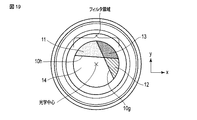
更に、本実施形態においては第1〜第4のフィルタ領域11〜14が図2に示すように同一の大きさの扇型形状であるものとして説明したが、例えば図18に示す2本の線10e及び10fによってフィルタ10が分割されるように、第1〜第4のフィルタ領域11〜14の全てが同一の形状でなくても構わない。また、例えば図19に示す線10g及び10hのように、フィルタ10を第1〜第4のフィルタ領域11〜14に分割する2以上の線は、フィルタ10の中心で交差するものでなくてもよい。また、図示しないが、フィルタ10を第1〜第4のフィルタ領域11〜14に分割する線は直線でなく曲線であっても構わない。
Further, in the present embodiment, the first to
また、本実施形態においてはフィルタ10が4つのフィルタ領域に分割されるものとして説明したが、R画像及びB画像の畳み込み方向が異なるようにRフィルタ領域及びBフィルタ領域が配置されており、かつ、フィルタ10に含まれるフィルタ領域の全てが緑色の波長領域の光を透過するように構成されていれば、フィルタ領域の数は5以上であっても構わない。なお、G画像に相当する基準画像を生成することが可能であれば、フィルタ10に含まれる少なくとも1つのフィルタ領域が緑色の波長領域の光を透過しない構成であってもよい。
Further, although the
ここで、本実施形態においては、フィルタ10に含まれる第1〜第4のフィルタ領域11〜14の全てを透過する波長領域の光の色(以下、共通色と表記)が緑色である場合について説明したが、これは、緑色の波長領域を受光するセンサ(第2のセンサ32)が赤色の波長領域を受光するセンサ(第1のセンサ31)及び青色の波長領域を受光するセンサ(第3のセンサ33)よりも多く配置されたイメージセンサ30が採用されている場合が多いためである。このようなイメージセンサ30の場合には、共通色を緑色とすることにより、イメージセンサ30が受光する光量を増加させることができる。
Here, in the present embodiment, a case where the color of light in the wavelength region that transmits all of the first to
なお、共通色は緑色に限られない。例えば第1のフィルタ領域11を「イエローフィルタ」とし、第2のフィルタ領域12を「マゼンタ(M:Magenta)フィルタ」とし、第3のフィルタ領域13を「レッド(R:Red)フィルタ」とし、第4のフィルタ領域14を「透明フィルタ」とした場合には、赤色を共通色とするフィルタ10を用いることができる。「マゼンタフィルタ」は、赤色の波長領域の光と青色の波長領域の光とを透過する(つまり、緑色の波長領域の光を透過しない)フィルタである。この場合には、G画像の補正後のぼけ形状とR画像のぼけ形状(基準ぼけ形状)とを比較する、またはB画像の補正後のぼけ形状とR画像のぼけ形状とを比較することによって、被写体距離を算出することができる。
The common color is not limited to green. For example, the
同様に、例えば第1のフィルタ領域11を「マゼンタフィルタ」とし、第2のフィルタ領域12を「シアンフィルタ」とし、第3のフィルタ領域13を「ブルー(B:Blue)フィルタ」とし、第4のフィルタ領域14を「透明フィルタ」とした場合には、青色を共通色とするフィルタ10を用いることができる。この場合には、R画像の補正後のぼけ形状とB画像のぼけ形状(基準ぼけ形状)とを比較する、またはG画像の補正後のぼけ形状とB画像のぼけ形状とを比較することによって、被写体距離を算出することができる。
Similarly, for example, the
なお、本実施形態においては、説明の便宜上、フィルタ10が円形状であるものとして説明したが、当該フィルタ10は、撮像装置100の開口部の形状に応じた形状であっても構わない。具体的には、フィルタ10の外周が撮像装置100の絞り羽形状に形成されていてもよいし、例えばフィルタ10が多角形(例えば、六角形及び八角形等)の形状を有していてもよい。
In the present embodiment, for convenience of description, the
上記したように本実施形態は、様々な形状または配置の第1〜第4のフィルタ領域11〜14を含むフィルタ10で実現することが可能であるが、当該第1〜第4のフィルタ領域11〜14の形状は、例えば撮像装置100上のハードウェアの制約等に基づいて定められても構わない。具体的には、R画像またはB画像のぼけ形状に補正フィルタを畳み込む(つまり、当該ぼけ形状にぼけを付加する)際にはラインメモリが用いられるが、例えばR画像またはB画像の畳み込み方向によって必要なラインメモリの容量が異なる。このため、第1〜第4のフィルタ領域11〜14の形状(つまり、R画像またはB画像の畳み込み方向)は、ラインメモリの容量に従って設定されても構わない。すなわち、第1〜第4のフィルタ領域11〜14の形状は、ラインメモリで畳み込みが可能なように定められてもよい。
As described above, the present embodiment can be realized by the
また、上記したようにR画像及びB画像のうちの例えばR画像の畳み込み方向がエッジに沿うような方向である場合には、当該R画像を用いて被写体距離を算出することができない。この場合には、B画像を用いて被写体距離を算出することは可能であるが、精度を向上させるためにはR画像及びB画像の双方を用いて被写体距離を算出することが好ましい。このため、例えば撮像装置100によって撮像される被写体等により、撮像画像中のエッジの向きが想定されるような場合には、R画像及びB画像の畳み込み方向が当該エッジの向きと異なるように第1〜第4のフィルタ領域11〜14の形状が定められるようにしてもよい。
Further, as described above, when the convolution direction of the R image of the R image and the B image is along the edge, the subject distance cannot be calculated using the R image. In this case, it is possible to calculate the subject distance using the B image, but it is preferable to calculate the subject distance using both the R image and the B image in order to improve accuracy. Therefore, for example, when the orientation of the edge in the captured image is assumed due to the subject captured by the
また、R画像またはB画像の畳み込み方向を水平方向とした場合には、他の方向である場合に比べて、離散化誤差の影響を低減し、精度を向上させることができる。このため、R画像及びB画像の畳み込み方向のうちの一方が水平方向となるように第1〜第4のフィルタ領域11〜14の形状が定められるようにしてもよい。
Further, when the convolution direction of the R image or the B image is the horizontal direction, the influence of the discretization error can be reduced and the accuracy can be improved, as compared with the case of the other directions. Therefore, the shapes of the first to
なお、上述した図2に示すようにR画像の畳み込み方向を水平方向とし、B画像の畳み込み方向が当該R画像の畳み込み方向と直交する構成によれば、精度を向上させるとともに撮像画像中のエッジに対する高い頑健性(ロバスト性)を実現することが可能である。 Note that, as shown in FIG. 2 described above, according to the configuration in which the convolution direction of the R image is the horizontal direction and the convolution direction of the B image is orthogonal to the convolution direction of the R image, accuracy is improved and edges in the captured image are improved. It is possible to realize high robustness against (robustness).
上記したように第1〜第4のフィルタ領域11〜14の形状(または配置)を定める(変更する)ことによって様々なR画像及びB画像の畳み込み方向を実現することができるが、異なる距離dの各々に対応する複数の補正フィルタは、当該畳み込み方向に従って予め用意されていればよい。すなわち、R画像及びB画像の畳み込み方向にぼけを付加するような補正フィルタが予め用意されていればよい。
Various convolution directions of the R image and the B image can be realized by defining (changing) the shapes (or arrangements) of the first to
また、本実施形態においては、異なる距離dに対応する補正フィルタによって補正されたR画像またはB画像のぼけ形状(第1のぼけ形状)とG画像のぼけ形状(第2のぼけ形状)とを比較することによって被写体距離を算出する構成であるから、汎用のイメージセンサを利用して高精度に距離情報を取得することが可能となる。なお、例えばR画像及びB画像をステレオカメラで撮影した2つの画像と同視し、当該R画像及びB画像間の視差量に基づいて被写体距離を算出するような構成とすることも可能である。 In addition, in the present embodiment, the blur shape (first blur shape) of the R image or B image and the blur shape (second blur shape) of the G image corrected by the correction filters corresponding to different distances d are set. Since the subject distance is calculated by comparison, it is possible to obtain the distance information with high accuracy using a general-purpose image sensor. Note that, for example, the R image and the B image may be regarded as two images captured by a stereo camera, and the subject distance may be calculated based on the parallax amount between the R image and the B image.
更に、本実施形態においては、算出された被写体距離を示す距離情報に基づいて加工された画像(例えば、距離画像等)を出力することができる。このような距離画像によれば、撮像装置100から被写体までの距離を容易に把握することが可能となる。
Furthermore, in the present embodiment, it is possible to output an image (for example, a distance image or the like) processed based on the distance information indicating the calculated subject distance. With such a distance image, it is possible to easily grasp the distance from the
なお、本実施形態においては、赤色、緑色及び青色を検出(受光)するRGBセンサを含むイメージセンサ30を用いるものとして説明したが、他の色を検出するセンサを含むイメージセンサが用いられても構わない。この場合であっても、センサによって検出される色に応じた本実施形態におけるフィルタを設けることによって、同様に距離情報を取得することができる。
In the present embodiment, the
なお、本実施形態においては、被写体距離を示す距離情報を取得することができるため、撮像装置100によって撮像された空間の3次元情報を得ることが可能となる。なお、本実施形態において得ることができる(つまり、撮像装置100から出力される)3次元情報は、例えば被写体の位置、当該被写体の移動、当該被写体までの距離及び当該被写体が所定範囲の内/外にいること等に関する情報である。この3次元情報は、本実施形態において説明した以外にも様々な処理等に利用することが可能となる。
In addition, in the present embodiment, since it is possible to acquire the distance information indicating the object distance, it is possible to obtain the three-dimensional information of the space imaged by the
具体的には、本実施形態に係る撮像装置100は、例えば図20に示すような予め定められた範囲(内に存在する人物等)を監視する監視システムに適用することが可能である。
Specifically, the
ここで、図21は、本実施形態における監視システム1000の機能構成の一例を示すブロック図である。ここでは、監視システム1000が、例えば施設内等における人の流れを時間帯毎に把握するためのシステムであることを想定する。
Here, FIG. 21 is a block diagram showing an example of the functional configuration of the
図21に示すように、監視システム1000は、撮像装置100、制御部1001及びユーザインタフェース部1002を有する。撮像装置100及び制御部1001は、優先または無線のネットワーク経由で接続してもよい。
As shown in FIG. 21, the
制御部1001は、撮像装置100に連続的に撮像を行わせ、撮像装置100によって撮像された被写体の画像を、ユーザインタフェース部1002を介して表示する。ユーザインタフェース部1002は、例えば、ディスプレイ装置等への表示処理と、キーボードまたはポインティングデバイスからの入力処理とを実行する。ディスプレイ装置とポインティングデバイスとは、例えばタッチスクリーンディスプレイ等の一体型のデバイスであってもよい。
The
また、制御部1001は、撮像装置100から順次出力される人物(被写体)の3次元情報に基づき、例えば人物が通路のどの辺りをどの方向に歩いているか等の人の流れを解析し、当該解析結果を例えばHDD(Hard Disk Drive)等の記憶装置に記録する。なお、この解析は、必ずしもリアルタイムに実行されるものでなくてもよく、記憶装置に蓄積された被写体の3次元情報を用いるバッチ処理として実行されてもよい。
Further, the
続いて、図22を参照して、撮像装置100によって撮像される被写体の追跡における3次元情報(距離情報)の活用例について説明する。
Next, with reference to FIG. 22, an example of utilizing the three-dimensional information (distance information) in tracking a subject imaged by the
ここでは、人物Xが、撮像装置100から見て左から右へ移動し、人物Yが、逆に、右から左へと移動しようとしている場合を想定する(A)。また、身長の低い人物Xが身長の高い人物Yよりも撮像装置100から見て手前に位置しており、人物X及びYが互いに重なる位置となった場合に、画像上の人物像のサイズが略一致した状態となるものとする。
Here, it is assumed that the person X moves from left to right as viewed from the
人物X及びYが上記のように移動すると、ある時点で画像上の人物像(被写体像)が重なり(B)、その後、左右に離れていく(C)。このような場合、距離を用いず、例えば画像認識のみで人物像を追跡すると、人物像の交差時、追跡対象を取り違えて、人物X及びYがそれぞれUターンしたように誤追跡してしまう可能性がある。 When the persons X and Y move as described above, the person images (subject images) on the images overlap at a certain point (B), and then move away from side to side (C). In such a case, if the human image is tracked only by image recognition without using the distance, when the human images intersect each other, the tracking target may be confused, and the people X and Y may be mistracked as if they were U-turned. There is a nature.
これに対して、3次元情報(距離)を用いることで、人物像の交差時に追跡対象の取り違えを起こしてしまうという事態を防止することができる。 On the other hand, by using the three-dimensional information (distance), it is possible to prevent a situation in which the tracking target is mistaken when the human images intersect.
なお、このような監視システム1000は、例えば被写体が予め定められた行動以外の行動(例えば、進入禁止エリアへの進入)をした際に警報を出力するような場合に用いられてもよい。被写体が予め定められた行動以外の行動をしたか否かは、上記した被写体の位置、当該被写体の移動、当該被写体までの距離及び当該被写体が所定範囲の内/外にいること等に基づいて判定することができる。
It should be noted that such a
また、本実施形態に係る撮像装置100は、例えば各種移動体の動作を制御する自動制御システムに利用されても構わない。
Further, the
ここで、図23は、本実施形態における自動制御システム1100の機能構成の一例を示すブロック図である。ここでは、図24に示すように、自動制御システム1100によって動作が制御される移動体が、例えば自動車である場合を想定する。
Here, FIG. 23 is a block diagram showing an example of a functional configuration of the
図23に示すように、自動制御システム1100は、撮像装置100、制御部1101及び駆動機構1102を有する。図24に示すように、撮像装置100は、例えば自動車の進行方向の被写体を撮像するように当該自動車(移動体)に設置される。なお、自動車の進行方向の被写体を撮像するように設置される形態としては、前方を撮像するいわゆるフロントカメラとして設置されるほか、バック時に後方を撮像するいわゆるリアカメラとして設置され得る。もちろん、これら両方が設置されてもよい。また、撮像装置100は、いわゆるドライブレコーダとしての機能を兼ねて設置されるものであってもよい。すなわち、撮像装置100は、録画機器であってもよい。
As shown in FIG. 23, the
制御部1101は、撮像装置100から出力される3次元情報に基づいて、自動車を動作(移動)させる駆動機構1102を制御する。この場合、例えば進行方向にある被写体へ所定の距離まで近づいた際に、移動する自動車を停止させたり減速させたり加速させたり、停止している自動車を移動させたりすることができる。あるいは、制御部1101は、被写体が所定の距離以上離れたら、自動車を停止、減速、加速、移動させるように駆動機構1102を制御してもよい。あるいは、制御部1101は、被写体へ所定の距離まで近づいた場合に自動車の動作モードを通常駆動モードから衝突回避モードへ切り替えてもよいし、被写体が所定の距離以上離れた場合に当該動作モードを衝突回避モードから通常駆動モードに切り替えてもよい。なお、制御部1101による制御の基準となる所定の距離は、例えばユーザによって任意に設定される閾値である。
The
このような自動制御システム1100によれば、例えば自動車の走行中において、先行車の3次元情報(距離情報)に基づいて自動車が先行車に追従するように自動運転する、または当該先行車に追突しないようにブレーキを自動的に制御するといったことが可能となる。また、、自動車の後方に存在する物体(被写体)の3次元情報を利用することによって、自動車がバックする場合において、自動車の後方の予め定められた距離より近い位置に障害物等が存在する場合には、自動的にブレーキをかける、またはバックできないようにするといったことが可能となる。また、先行車の3次元情報(距離情報)に基づいて、自動車と当該先行車との距離が一定になるように制御することも可能である。これによれば、自動制御システムによって動作(移動)が制御される複数の自動車による連隊走行等を容易に実現することができる。
According to such an
上記した移動体は、自動車を含む車両に限らず、移動用の駆動機構を有するものであるならば、ドローンまたは飛行機等の飛翔体及び船舶等であってもよいし、産業用ロボット、AGV(Automatic Guided Vehicle)、お掃除ロボット及びコミュニケーションロボット等の各種ロボットであっても構わない。 The above-mentioned moving body is not limited to a vehicle including an automobile, and may be a flying body such as a drone or an airplane and a ship as long as it has a driving mechanism for movement, an industrial robot, an AGV ( Various robots such as an automatic guided vehicle), a cleaning robot, and a communication robot may be used.
図25は、本実施形態におけるロボットの動作を制御する自動制御システム1200の機能構成の一例を示すブロック図である。ここでは、ロボットが、例えば複数種の製品を生産し得る生産ライン等に設置される産業用ロボットであることを想定する。
FIG. 25 is a block diagram showing an example of the functional configuration of an
図25に示すように、自動制御システム1200は、撮像装置100、制御部1201、駆動機構1202及び回転機構1203を有する。
As shown in FIG. 25, the
制御部1201は、撮像装置から出力される作業の対象物である被写体の3次元情報に基づいて、駆動機構1202を制御する。駆動機構1202は、例えば対象物に部材を取り付けたり、対象物を積み上げて所定の場所へ搬送したりするためのロボットアームを駆動する。なお、撮像装置100は、回転機構203を介して例えばロボットアーム(の手のひらまたは手首等)に搭載されている。
The
このような自動制御システムにおいては、例えばロボットアームに搭載された撮像装置100から出力されるロボットの周辺に存在する物体(被写体)の3次元情報を利用することによって、当該ロボットに所定の物体を掴ませるといった制御を行うことが可能となる。
In such an automatic control system, for example, by using the three-dimensional information of an object (subject) existing around the robot, which is output from the
なお、上記したように例えばR画像の畳み込み方向が撮像画像中のエッジに沿う方向と一致する場合には、当該R画像を用いて被写体距離を算出することができない。この場合、制御部1201が回転機構1203を制御することによって撮像装置100を回転させることで、R画像の畳み込み方向が撮像画像中のエッジに沿う方向と一致しないようにすることも可能である。ここではR画像について説明したが、B画像の畳み込み方向が撮像画像中のエッジに沿う方向と一致する場合についても同様である。このような構成によれば、R画像及びB画像の双方を用いて被写体距離を算出することが可能であるため、当該被写体距離の算出精度を向上させることができる。
Note that, as described above, for example, when the convolution direction of the R image matches the direction along the edge in the captured image, the subject distance cannot be calculated using the R image. In this case, the
また、上記した自動制御システム1200は、AGVまたはお掃除ロボットの動作を制御する場合に用いられても構わない。この場合には、AGVまたはお掃除ロボットの前方等に存在する物体(被写体)の3次元情報を利用することによって、障害物を回避するような軌道で当該AGVまたはお掃除ロボットを移動させるといったことが可能となる。
Further, the
更に、上記した自動制御システム1200は、人物とコミュニケーションを行うコミュニケーションロボットの動作を制御する場合に用いられても構わない。この場合には、コミュニケーションロボットの前方等に存在する人物(被写体)の3次元情報を利用することによって、当該コミュニケーションロボットの所定範囲内に人物が近づいた場合に、当該人物とのコミュニケーションを開始させるといったことが可能となる。
Further, the above-described
なお、上記した移動体が例えばドローンである場合には、当該ドローンの前方等に存在する物体(被写体)の3次元情報を利用することによって、障害物を回避するような軌道で当該ドローンを飛行させるといったことが可能となる。 When the above-mentioned moving body is a drone, for example, the three-dimensional information of an object (subject) existing in front of the drone is used to fly the drone in a trajectory that avoids obstacles. It is possible to make it happen.
更に、移動体がドローンである場合、上空からのひび割れや電線破断等の点検時に、撮像装置100が点検対象を撮像した画像を取得し、当該点検対象(被写体)の3次元情報(距離情報)を取得する。この場合には、点検対象との距離に基づいて、当該点検対象との距離が一定になるようにドローンの推力を制御することによって、当該ドローンを点検対象に平行して飛行させることが可能となる。同様に、ドローンを例えば先行するドローンとの距離が一定になるように飛行させることにより、当該ドローンの連隊飛行等を容易に実現することができる。更に、ドローンを例えば地面(上に存在する被写体)との距離が一定になるように飛行させることにより、当該ドローンを一定の(指定された)高さで飛行させることができる。
Furthermore, when the moving body is a drone, the
上記したように本実施形態においては、撮像装置100から出力される被写体の3次元情報に基づいて、各種移動体またはその一部分の加速、減速、方向転換、通常運転モードと自動運転モード(例えば、衝突回避モード)との切り替え、及びエアバック等の安全装置の作動のうちの少なくとも1つに関する制御を実行することができる。具体的には、被写体が所定の距離よりも手前に存在する場合には、例えば減速、衝突回避、被写体から遠ざかる方向への方向転換、及び安全装置の作動のうちの少なくとも1つが実行され得る。また、被写体が所定の距離よりも奥に存在する場合には、例えば加速、及び被写体に近寄る方向への方向転換のうちの少なくとも1つが実行され得る。
As described above, in the present embodiment, based on the three-dimensional information of the subject output from the
更に、上記した自動制御システムによって動作が制御される移動体は、例えば自動ドアを含む概念であってもよい。図26は、自動ドアの動作を制御する自動制御システム(以下、自動ドアシステムと表記)1300の機能構成の一例を示す。図26に示すように、自動ドアシステム1300は、制御部1301、駆動機構1302及びドア部1303を有する。
Furthermore, the moving body whose operation is controlled by the above-mentioned automatic control system may be a concept including an automatic door, for example. FIG. 26 shows an example of the functional configuration of an automatic control system (hereinafter referred to as an automatic door system) 1300 that controls the operation of the automatic door. As shown in FIG. 26, the
自動ドアシステム1300において、撮像装置100は、自動ドアを通過しようとする人物(被写体)を撮像可能な位置に設置される。
In the
制御部1301は、撮像装置100から出力された被写体(人物)の3次元情報に基づいて、ドア部1303を開閉させるように駆動機構1302を制御する。具体的には、制御部1301は、被写体が所定の距離よりも手前にいる場合には、ドア部1303が開いた状態となるように駆動機構1302を制御する。また、制御部1301は、被写体が所定の距離よりも奥にいる場合には、ドア部1303が閉じた状態となるように駆動機構1302を制御する。なお、ドア部1303が開いた状態にあるときに、被写体が所定の距離よりも手前にいる場合には、制御部1301は、ドア部1303を開いたままとするように駆動機構1302を制御してもよい。ドア部1303が閉じた状態にある場合、制御部1301は、被写体と所定の距離との関係に応じて、ドア部1303を閉じたままとするように駆動機構1302を制御してもよい。被写体が所定の距離の奥から手前に移動したときに、制御部1301は、ドア部1303を開けるように駆動機構1302を制御してもよい。更に、被写体が所定の距離の手前から奥に移動したときに、制御部1301は、ドア部1303を閉じるように駆動機構1302を制御してもよい。
The
駆動機構1302は、例えばモーターを有し、当該モーターの駆動をドア部1303に伝達することによって、ドア部1303を開閉する。駆動機構1302は、制御部1201による制御に基づいて、ドア部1303が開いた状態または閉じた状態になるように当該ドア部1303を駆動する。
The drive mechanism 1302 has, for example, a motor, and transmits the drive of the motor to the
図27及び図28は、自動ドアシステム1300の動作例を示す。図27及び図28に示す例では、ドア部1303の正面を移動する歩行者(人物)等を撮影できる位置である例えばドア部1303の上方に、撮像装置100が設置されている。つまり、撮像装置100は、ドア部1303の正面の通路等を俯瞰した画像が取得できるように設置されている。
27 and 28 show an operation example of the
ここで、自動ドアシステム1300における制御部1301は、撮像装置100から出力される3次元情報に基づいて、被写体である歩行者1300aが基準面1300bよりも手前にいるか否かを判定することができる。この場合、撮像装置100によって撮像された複数の被写体を含む画像において、指定された特定の被写体のみを自動ドアシステム1300において対象とする人物(つまり、歩行者1300a)としてもよい。
Here, the
基準面1300bは、例えばドア部1303正面の、当該ドア部1303から一定の距離に設定される。基準面1300bは、例えばドア部1303と平行な平面である。基準面1300bと撮像装置100のレンズ20の光軸とは、直交していてもよいし、直交していなくてもよい。なお、基準面は、平面であるものとして説明するが、曲面であってもよい。
The
制御部1301は、図27に示すように歩行者1300aが基準面1300bよりも手前にいる場合、ドア部1303を開いた状態にするように駆動機構1302を制御する。駆動機構1302は、制御部1301による制御に基づいて、ドア部1303が開いた状態になるように当該ドア部1303を駆動する。
When the
また、制御部1301は、図28に示すように歩行者1300aが基準面1300bよりも奥にいる場合、ドア部1303を閉じた状態にするように駆動機構1302を制御する。駆動機構1302は、制御部1301による制御に基づいて、ドア部1303が閉じた状態になるように当該ドア部1303を駆動する。
Further, as shown in FIG. 28, the
ここでは、歩行者1300aが基準面1300bよりも手前にいるか奥にいるかに応じてドア部1303の開閉を制御する場合について説明したが、制御部1301は、例えば歩行者1300aが基準面1300bの手前から奥に移動したこと、及び歩行者1300aが基準面1300bの奥から手前に移動したことに応じてドア部1303の開閉を制御してもよい。具体的には、歩行者1300aが基準面1300bの手前から奥に移動した場合にドア部1303を閉じた状態にし、歩行者1300aが基準面1300bの奥から手前に移動した場合にドア部1303を開いた状態にしてもよい。
Here, the case where the opening/closing of the
更に、歩行者1300aが基準面1300bの手前に所定の時間滞在し続けた場合にドア部1303を開いた状態にするようにしてもよいし、歩行者1300aが基準面1300bの奥に所定の時間滞在し続けた場合にドア部1303を閉じた状態にするようにしてもよい。
Further, the
また、歩行者1300aが基準面1300bの手前に滞在し続けている間はドア部1303の開いた状態が維持されるようにしてもよいし、歩行者1300aが基準面1300bの奥に滞在し続けている間はドア部1303の閉じた状態が維持されるようにしてもよい。
Further, while the
上記したような自動ドアシステム1300によれば、ドア部1303(自動ドア)に設けられているセンサ(人物の存在を検出するためのセンサ)に加えて、撮像装置100から出力されるドア部1303の周辺に存在する人物の3次元情報を利用することによって、自動ドアの利用者の利便性を向上させることが可能となる。例えばドア部1303に向かってくる人物の距離の遷移を監視することによって当該人物の速度が予め定められた速度よりも早い(つまり、当該人物が走ってドア部1303に接近中である)と判定される場合には、上記したセンサによって人物の存在が検出されるよりも前にドア部1303を開いた状態にするといったことが可能となる。これによれば、人物がドア部1303に衝突することを回避することが可能となる。なお、この場合における撮像装置100は、自動ドア(ドア部1303)を通過する人物を監視するために用いられても構わない。
According to the
(第2の実施形態)
次に、第2の実施形態について説明する。なお、本実施形態に係る撮像装置のハードウェア構成及び機能構成については、前述した第1の実施形態と同様であるため、適宜、図1及び図4等を用いて説明する。また、以下の説明においては、前述した第1の実施形態と同様の部分についてはその詳しい説明を省略し、当該第1の実施形態と異なる部分について主に述べる。
(Second embodiment)
Next, a second embodiment will be described. The hardware configuration and the functional configuration of the image pickup apparatus according to the present embodiment are the same as those in the above-described first embodiment, and thus will be appropriately described with reference to FIGS. 1 and 4. Further, in the following description, detailed description of the same parts as those in the above-described first embodiment will be omitted, and parts different from the first embodiment will be mainly described.
本実施形態は、フィルタ10に含まれるフィルタ領域11〜14の形状及び配置が前述した第1の実施形態とは異なる。
The present embodiment is different from the above-described first embodiment in the shape and arrangement of the
以下、図29を参照して、本実施形態に係る撮像装置100の開口部に設けられているフィルタ10の一例について説明する。
Hereinafter, with reference to FIG. 29, an example of the
本実施形態におけるフィルタ10は、前述した第1の実施形態と同様に、カラーフィルタであり、特定の波長帯の光を透過する。本実施形態において、第1〜第4のフィルタ領域11〜14は、図29に示すように配置されている。
The
具体的には、第1〜第4のフィルタ領域11〜14は、フィルタ10を二分し、当該フィルタ10の一部である閉じた領域の外縁上の2点を通過する線によって形成される。換言すれば、フィルタ10(の領域)は、当該フィルタ10上の一定の範囲の領域を包含するように形成された線(第1の線)10iと、当該第1の線10i上の2点を通過し、当該フィルタ10の外周(外縁)と交わる線(第2の線)10jとによって4つの領域(第1〜第4のフィルタ領域11〜14)に分割されている。
Specifically, the first to
なお、図22に示す例では、上記した閉じた領域は円であり、第1の線10iは、フィルタ10の中央を中心とする円形状の領域を包含するように形成されている。第2の線10jは、第1の線10iによって包含されている円形状の領域の中心を通過する(つまり、円である閉じた領域を二分する)直線を含む。
In the example shown in FIG. 22, the closed area is a circle, and the
以下の説明においては、第1の線10iによって包含される円形状の領域を内側領域、フィルタ10の外周と第1の線10iとの間の領域を外側領域と称とする。
In the following description, the circular region included by the
本実施形態において、第1のフィルタ領域11及び第4のフィルタ領域14は、内側領域において隣り合う(向かい合う)位置に配置されている。第2のフィルタ領域12及び第3のフィルタ領域13は、外側領域において隣り合う(向かい合う)位置に配置されている。また、第1のフィルタ領域11及び第3のフィルタ領域13は接するように配置されており、第2のフィルタ領域12及び第4のフィルタ領域14は接するように配置されている。すなわち、本実施形態におけるフィルタ10は、図29に示すように、第1のフィルタ領域11が内側領域の右側、第2のフィルタ領域12が外側領域の左側、第3のフィルタ領域13が外側領域の右側、第4のフィルタ領域14が内側領域の左側にそれぞれ配置されるように構成されている。
In the present embodiment, the
なお、第1のフィルタ領域11は、赤色の波長領域の光と緑色の波長領域の光とを透過する「イエローフィルタ」によって構成される。
The
第2のフィルタ領域12は、緑色の波長領域の光と青色の波長領域の光とを透過する「シアンフィルタ」によって構成される。
The 2nd filter area|
第3のフィルタ領域13は、緑色の波長領域の光を透過する「グリーンフィルタ」によって構成される。
The
第4のフィルタ領域14は、赤色の波長領域の光と緑色の波長領域の光と青色の波長領域の光とを透過する「透明フィルタ」によって構成される。
The
すなわち、第1〜第4のフィルタ領域11〜14の透過率特性は、前述した第1の実施形態と同様にそれぞれ異なる。
That is, the transmittance characteristics of the first to
本実施形態においては、このような透過率特性により、第1のフィルタ領域11及び第4のフィルタ領域14(つまり、内側領域)は、赤色の波長領域の光を透過する。また、第2のフィルタ領域12及び第4のフィルタ領域14(つまり、フィルタ10の左半分の領域)は、青色の波長領域の光を透過する。更に、第1〜第4のフィルタ領域11〜14は、緑色の波長領域の光を透過する。
In this embodiment, due to such transmittance characteristics, the
なお、前述した第1の実施形態において説明したように、「透過する」とは、対応する波長領域の光を高い透過率で透過し、当該波長領域の光の減衰8すなわち、光量の低下)が極めて小さきことを意味する。 As described in the first embodiment, “transmitting” means transmitting light in the corresponding wavelength region with high transmittance, and attenuating the light in the wavelength region 8 (that is, reducing the amount of light). Means that is extremely small.
次に、本実施形態に係る撮像装置100の処理手順について説明する。ここでは、便宜的に、前述した図5のフローチャートを用いて説明する。
Next, a processing procedure of the
まず、撮像装置100による被写体の撮像が開始されると、撮像装置100に設けられているフィルタ10及びレンズ20を透過した光がイメージセンサ30に到達する。
First, when the image pickup of the subject by the
この場合、イメージセンサ30に含まれる第1のセンサ31(Rセンサ)は、第1のフィルタ領域11及び第4のフィルタ領域14を透過した光から赤色の波長領域の光を検出(受光)してR画像を生成する(ステップS1)。このステップS1において生成されるR画像は、リファレンス画像等と比較して変化した画像となる。
In this case, the first sensor 31 (R sensor) included in the
ここで、図30を参照して、第1のセンサ31によって生成されるR画像について概念的に説明する。なお、図23に示すG画像のぼけ形状については、図6等において説明したものと同様であるため、その詳しい説明を省略する。
Here, the R image generated by the
上述したように撮像装置100の開口部に設けられるフィルタ10には透過率特性の異なる第1〜第4のフィルタ領域11〜14が含まれるが、以下の説明においては、当該第1〜第4のフィルタ領域11〜14のうち赤色の波長領域の光を透過する第1のフィルタ領域11及び第4のフィルタ領域14を含む領域(つまり、フィルタ10の内側領域)を便宜的にRフィルタ領域501と称する。なお、図30の右列と中列はイメージセンサ30上に形成される画像のぼけ形状を表し、左列は、それぞれ撮像装置100を上方向(つまり、Y軸の正方向)から見た場合におけるレンズ20及びフィルタ10の組み合わせとイメージセンサ30とを示している。
As described above, the
まず、被写体の位置がピント位置よりも遠い、つまり、距離d>0の場合を想定する。この場合、被写体にはピントが合っていないため、R画像においては、ぼけが生じる。 First, assume that the position of the subject is farther than the focus position, that is, the distance d>0. In this case, since the subject is out of focus, blurring occurs in the R image.
また、上記したようにR画像は、Rフィルタ領域(フィルタ10の内側領域)501を透過した光に基づいて生成される画像である。このため、距離d>0の場合のR画像のぼけ形状501aは、図30の上段に示すように、例えばG画像のぼけ形状202aと比較して当該ぼけ形状202aが縮小されたような形状となる。
Further, as described above, the R image is an image generated based on the light that has passed through the R filter region (region inside the filter 10) 501. Therefore, the
すなわち、R画像のぼけ形状501aは、Rフィルタ領域501の形状(大きさ)に応じた点対称形状である。
That is, the
次に、被写体の位置がピント位置に一致する、つまり、距離d=0の場合を想定する。図30の中段に示すように、この場合のR画像においては、ぼけは生じない。 Next, assume that the position of the subject matches the focus position, that is, the distance d=0. As shown in the middle part of FIG. 30, blurring does not occur in the R image in this case.
更に、被写体の位置がピント位置よりも近い、つまり、距離d<0の場合を想定する。この場合、被写体にはピントが合っていないため、R画像においては、ぼけが生じる。 Furthermore, it is assumed that the position of the subject is closer than the focus position, that is, the distance d<0. In this case, since the subject is out of focus, blurring occurs in the R image.
また、上記したようにR画像はRフィルタ領域501を透過した光に基づいて生成される画像であるが、距離d<0の場合のR画像のぼけ形状501bは、例えばG画像のぼけ形状202bと比較して当該ぼけ形状202bが縮小されたような形状となる。なお、ぼけ形状501bの形状は、上記したぼけ形状501aと同様となる。
Further, as described above, the R image is an image generated based on the light transmitted through the
再び図5に戻ると、イメージセンサ30に含まれる第2のセンサ32(Gセンサ)は、第1〜第4のフィルタ領域11〜14を透過した光から緑色の波長領域の光を検出してG画像を生成する(ステップS2)。
Returning to FIG. 5 again, the second sensor 32 (G sensor) included in the
なお、緑色の波長領域の光は全てのフィルタ領域を透過するため、G画像は、リファレンス画像に近い画像となる。 Since the light in the green wavelength region passes through all the filter regions, the G image is an image close to the reference image.
次に、イメージセンサ30に含まれる第3のセンサ33(Bセンサ)は、第2のフィルタ領域12及び第4のフィルタ領域14を透過した光から青色の波長領域の光を検出(受光)してB画像を生成する(ステップS3)。このステップS3において生成されるB画像は、リファレンス画像等と比較して変化した画像となる。
Next, the third sensor 33 (B sensor) included in the
ここで、図31を参照して、第3のセンサ33によって生成されるB画像について概念的に説明する。なお、図24に示すG画像のぼけ形状については、図23と同様であるため、その詳しい説明を省略する。
Here, the B image generated by the
上述したように撮像装置100の開口部に設けられるフィルタ10には透過率特性の異なる第1〜第4のフィルタ領域11〜14が含まれるが、以下の説明においては、当該第1〜第4のフィルタ領域11〜14のうち青色の波長領域の光を透過する第2のフィルタ領域12及び第4のフィルタ領域14を含む領域(つまり、撮像装置100によって撮像される被写体側から見た場合におけるフィルタ10の左半分の領域)を便宜的にBフィルタ領域502と称する。なお、図24の右列と中列はイメージセンサ30上に形成される画像のぼけ形状を表し、左列は、それぞれ撮像装置100を上方向(つまり、Y軸の正方向)から見た場合におけるレンズ20及びフィルタ10の組み合わせとイメージセンサ30とを示している。
As described above, the
まず、被写体の位置がピント位置よりも遠い、つまり、距離d>0の場合を想定する。この場合、被写体にはピントが合っていないため、B画像においては、ぼけが生じる。 First, assume that the position of the subject is farther than the focus position, that is, the distance d>0. In this case, since the subject is out of focus, the B image is blurred.
また、上記したようにB画像は、Bフィルタ領域(フィルタ10の左半分の領域)502を透過した光に基づいて生成される画像である。このため、距離d>0の場合のB画像のぼけ形状502aは、例えばG画像のぼけ形状202aと比較して右側に偏った形状となる。
Further, as described above, the B image is an image generated based on the light transmitted through the B filter region (the left half region of the filter 10) 502. Therefore, the
すなわち、B画像のぼけ形状502aは、Bフィルタ領域203の形状に応じた非点対称形状(右側に偏った形状)である。
That is, the
次に、被写体の位置がピント位置に一致する、つまり、距離d=0の場合を想定する。図31の中段に示すように、この場合のB画像においては、ぼけは生じない。 Next, assume that the position of the subject matches the focus position, that is, the distance d=0. As shown in the middle part of FIG. 31, no blur occurs in the B image in this case.
更に、被写体の位置がピント位置よりも近い、つまり、距離d<0の場合を想定する。この場合、被写体にはピントが合っていないため、B画像においては、ぼけが生じる。 Further, it is assumed that the position of the subject is closer than the focus position, that is, the distance d<0. In this case, since the subject is out of focus, the B image is blurred.
また、上記したようにB画像はBフィルタ領域502を透過した光に基づいて生成される画像であるが、距離d<0の場合のB画像のぼけ形状502bは、例えばG画像のぼけ形状202bと比較して左側に偏った形状となる。
Further, as described above, the B image is an image generated based on the light transmitted through the
すなわち、ぼけ形状502bは、上記したぼけ形状502aと同様にBフィルタ領域502の形状に応じた非点対称形状であり、当該ぼけ形状502aをY軸方向に平行な位置直線を中心にして反転した形状となる。
That is, the
上記したようにR画像及びB画像においては、距離dに応じてぼけ形状が変化する。具体的には、R画像のぼけ形状は、距離d>0及び距離d<0の場合(つまり、距離d=0以外の場合)で、G画像のぼけ形状が縮小された形状(点対称形状)に変化する。一方、B画像のぼけ形状は、距離d>0であればG画像のぼけ形状の左側が欠けた半円形状のような形状(非点対称形状)に変化し、距離d<0であればG画像のぼけ形状の右側が欠けた半円形状のような形状(非点対称形状)に変化する。 As described above, in the R image and the B image, the blur shape changes according to the distance d. Specifically, the blur shape of the R image is a reduced shape (point symmetric shape) of the blur shape of the G image when the distance d>0 and the distance d<0 (that is, when the distance d is other than 0). ). On the other hand, if the distance d>0, the blur shape of the B image changes to a semicircular shape (asymmetrical shape) in which the left side of the blur shape of the G image is missing, and if the distance d<0. The right side of the blurred shape of the G image is changed to a shape such as a semicircular shape (asymmetrical shape).
なお、図30及び図31においては示されていないが、R画像、G画像及びB画像におけるぼけ形状の大きさ(幅)は、前述した第1の実施形態において説明したように距離|d|に依存する。 Although not shown in FIGS. 30 and 31, the size (width) of the blur shape in the R image, the G image, and the B image is the distance |d| as described in the first embodiment. Depends on.
再び図5に戻ると、上記したステップS1において生成されたR画像、ステップS2において生成されたG画像及びステップS3において生成されたB画像は、画像処理部110に含まれる入力部111によって入力される。
Returning to FIG. 5 again, the R image generated in step S1, the G image generated in step S2, and the B image generated in step S3 are input by the
距離算出部112は、入力部111によって入力されたR画像、G画像及びB画像に基づいて、被写体距離を算出する(ステップS4)。
The
なお、ステップS4においては、前述した第1の実施形態と同様に、例えばリファレンス画像に近いG画像を基準として、上記したピント位置から被写体までの距離dに応じて変化するR画像及びB画像のぼけ形状と当該G画像のぼけ形状とを比較することによって撮像画像を構成する画素毎の被写体距離を算出する。 Note that, in step S4, similar to the above-described first embodiment, for example, with the G image close to the reference image as a reference, the R image and the B image that change according to the distance d from the focus position to the subject are described. By comparing the blur shape with the blur shape of the G image, the subject distance for each pixel forming the captured image is calculated.
ここで、リファレンス画像に近い画像であるG画像を基準画像、当該基準画像と比較してBのぼけ形状が変化しているR画像及びB画像の各々を対象画像とすると、距離算出部112は、任意の距離に対応する補正フィルタを適用して対象画像のぼけ形状を補正し、当該補正された対象画像のぼけ形状と基準画像のぼけ形状とを比較することによって被写体距離を算出する。
Here, assuming that the G image that is an image close to the reference image is the reference image, and the R image and the B image in which the blur shape of B is changed as compared with the reference image are target images, the
なお、対象画像がR画像である場合には、当該R画像のぼけ形状(G画像のぼけ形状が縮小されたような形状)の周囲にぼけを付加する補正フィルタが適用される。この場合、R画像のぼけ形状に対して2次元の補正フィルタの畳み込みが行われることによって、当該R画像のぼけ形状をG画像のぼけ形状に一致する形状に補正することが可能となる。なお、R画像のぼけ形状に補正フィルタを適用した後の処理は、前述した第1の実施形態と同様であるため、その詳しい説明を省略する。 When the target image is an R image, a correction filter that adds a blur around the blur shape of the R image (a shape in which the blur shape of the G image is reduced) is applied. In this case, the blur shape of the R image is convolved with the two-dimensional correction filter, so that the blur shape of the R image can be corrected to a shape that matches the blur shape of the G image. Note that the processing after applying the correction filter to the blurred shape of the R image is the same as that in the first embodiment described above, and thus detailed description thereof is omitted.
また、本実施形態におけるBフィルタ領域502と前述した第1の実施形態におけるRフィルタ領域201は、フィルタ10における同一の領域である。このため、本実施形態において対象画像がB画像である場合には、前述した第1の実施形態におけるR画像とG画像とを用いて距離dを特定する(つまり、被写体距離を算出する)場合と同様の処理が実行されればよい。
Further, the
ステップS4において画素毎に被写体距離が算出された場合、ステップS5の処理が実行される。なお、ステップS5の処理は、前述した第1の実施形態において説明した通りであるため、その詳しい説明を省略する。 When the subject distance is calculated for each pixel in step S4, the process of step S5 is executed. Since the process of step S5 is the same as that described in the first embodiment, detailed description thereof will be omitted.
上記したように本実施形態において、被写体を撮像するために入射した光を透過するフィルタ10は、当該フィルタ10を二分し、当該フィルタ10の一部である閉じた領域(内側領域)の外縁上の2点を通過する線によって形成された4つのフィルタ領域(第1〜第4のフィルタ領域11〜14)に分割されており、当該4つのフィルタ領域の透過率特性がそれぞれ異なるように構成されている。
As described above, in the present embodiment, the
具体的には、図29に示すように、第1の線10iはフィルタ10の中央を中心とする円形状の領域を包含するように形成されており、第2の線10jは当該円形状の領域の中心を通過する直線を含む。この第1の線10i及び第2の線10jによって第1〜第4のフィルタ領域11〜14が形成される。
Specifically, as shown in FIG. 29, the
本実施形態においては、このようなフィルタ10を透過した入射光に基づいて生成される撮像画像(R画像、B画像及びG画像)から被写体距離を算出することができるため、小型かつ低コストで高精度に距離情報を取得することが可能となる。
In the present embodiment, since the subject distance can be calculated from the captured images (R image, B image, and G image) generated based on the incident light that has passed through the
ここで、本実施形態におけるR画像のぼけ形状は、G画像のぼけ形状(基準ぼけ形状)が縮小されたような形状(点対称形状)である。このようなR画像のぼけ形状に対する畳み込み方向は、上記した第1の実施形態におけるR画像及びB画像とは異なり、一方向に限定されるものではない。このため、本実施形態においては、エッジの方向にかかわらず被写体距離を算出することが可能となる。 Here, the blur shape of the R image in the present embodiment is a shape (point-symmetrical shape) obtained by reducing the blur shape (reference blur shape) of the G image. The convolution direction of the R image with respect to the blur shape is not limited to one direction, unlike the R image and the B image in the first embodiment described above. Therefore, in the present embodiment, the subject distance can be calculated regardless of the edge direction.
なお、本実施形態において、B画像の畳み込み方向は水平方向(左右方向)であるため、水平方向のエッジ部分に関しては当該B画像を用いて距離dを算出することができない。この場合は、R画像を用いて距離dを算出することになるが、当該R画像のぼけ形状は点対称形状であることから、距離d>0の場合であっても距離d<0の場合であっても当該ぼけ形状は同一の形状となる。すなわち、R画像のみでは距離|d|を算出することは可能であるが、当該距離d>0及び距離d<0を区別することはできない。これに対しては、周辺の画素に対して特定の画素(に対応する箇所)のみ距離dの正負が反転する可能性は低いことから、例えば当該周辺の画素に対して算出された距離d(被写体距離)に基づいて当該特定の画素の距離d>0または距離d<0を区別するようにしてもよい。 In the present embodiment, the convolution direction of the B image is the horizontal direction (horizontal direction), and thus the distance d cannot be calculated using the B image for the edge portion in the horizontal direction. In this case, the distance d is calculated using the R image, but since the blur shape of the R image is a point symmetric shape, even if the distance d>0, the distance d<0 However, the blur shapes are the same. That is, the distance |d| can be calculated only with the R image, but the distance d>0 and the distance d<0 cannot be distinguished. On the other hand, since it is unlikely that the positive and negative signs of the distance d are inverted only in (a portion corresponding to) a specific pixel with respect to the peripheral pixels, for example, the calculated distance d( The distance d>0 or the distance d<0 of the specific pixel may be distinguished based on the subject distance).
更に、本実施形態においては、例えばイメージセンサ30の分光感度等に基づいて第1の線10iによって包含される内側領域の大きさ(内側領域の直径)を調整することが可能であるため、フィルタ10に含まれる第1〜第4のフィルタ領域11〜14の設計の自由度が高く、照明変化等に対する頑健性(ロバスト性)のコントロールが容易となる。
Further, in the present embodiment, the size of the inner region (diameter of the inner region) included by the
なお、図29に示す第1〜第4のフィルタ領域11〜14の配置(すなわち、フィルタ10の構成)は一例であり、フィルタ10は、例えば、上記したようにR画像のぼけ形状(Rフィルタ領域501)が点対称形状であり、B画像のぼけ形状(Bフィルタ領域502)が非点対称形状となるように第1〜第4のフィルタ領域11〜14が配置されていればよい。例えば、第1のフィルタ領域11と第4のフィルタ領域14とが入れ替えられ、かつ、第2のフィルタ領域12と第3のフィルタ領域13とが入れ替えられてもよい。
Note that the arrangement of the first to
また、本実施形態においては、図29に示す第1の線10iと第2の線10jとによってフィルタ10が4つのフィルタ領域に分割されるものとして説明したが、例えば図32に示すように第1の線10iと2以上の第2の線(例えば、第2の線10k及び10l)とによってフィルタ10が分割されても構わない。
Moreover, in the present embodiment, the
また、例えば図33に示す第2の線10mのように、第2の線は、フィルタ10の中心を通るものでなくてもよい。更に、図示しないが、例えば内側領域の形状が矩形形状となるように第1の線は複数の直線であってもよい。また、第2の線は曲線であってもよい。
Further, the second line may not pass through the center of the
また、本実施形態においては、フィルタ10が4つのフィルタ領域に分割されるものとして説明したが、R画像のぼけ形状がG画像のぼけ形状(点対称形状)を縮小したような形状となり、B画像のぼけ形状が非点対称形状となるようにRフィルタ領域及びBフィルタ領域が配置されており、かつ、フィルタ10に含まれるフィルタ領域の全てが緑色の波長領域の光を透過するように構成されていれば、フィルタ領域の数は5以上であっても構わない。なお、前述した第1の実施形態において説明したように、G画像に相当する基準画像を生成することが可能であれば、フィルタ10に含まれる少なくとも1つのフィルタ領域が緑色の波長領域の光を透過しない構成であってもよい。
Further, in the present embodiment, the
ここで、本実施形態においては、フィルタ10に含まれる第1〜第4のフィルタ領域11〜14の全てを透過する波長領域の光の色(共通色)が緑色である場合について説明したが、共通色を緑色とする場合には、上述した本実施形態におけるRフィルタ領域501をBフィルタ領域、Bフィルタ領域502をRフィルタ領域とするようにフィルタ10が構成されていても構わない。すなわち、第1のフィルタ領域11を「シアンフィルタ」とし、第2のフィルタ領域12を「イエローフィルタ」とし、第3のフィルタ領域13を「グリーンフィルタ」とし、第4のフィルタ領域14を「透明フィルタ」としてもよい。このような構成では、フィルタ10の内側領域(第1のフィルタ領域11及び第4のフィルタ領域14)がBフィルタ領域となり、フィルタ10の左半分の領域(第2のフィルタ領域12及び第4のフィルタ領域14)がRフィルタ領域となる。この場合においても、B画像(対象画像)及びG画像(基準画像)、R画像(対象画像)及びG画像(基準画像)をそれぞれ比較することによって被写体距離を算出することができる。
Here, in the present embodiment, a case has been described in which the color (common color) of light in the wavelength region that transmits all of the first to
また、共通色は、緑色に限られない。例えば第1のフィルタ領域11を「マゼンタフィルタ」とし、第2のフィルタ領域12を「イエローフィルタ」とし、第3のフィルタ領域13を「レッドフィルタ」とし、第4のフィルタ領域14を「透明フィルタ」とした場合には、赤色を共通色とするフィルタ10を用いることができる。このような構成では、フィルタ10の内側領域がBフィルタ領域となり、フィルタ10の左半分の領域がGフィルタ領域(緑色の波長領域の光を透過する領域)となる。また、共通色が赤色のフィルタ10の別の例としては、第1のフィルタ領域11を「イエローフィルタ」とし、第2のフィルタ領域12を「マゼンタフィルタ」とし、第3のフィルタ領域13を「レッドフィルタ」とし、第4のフィルタ領域14を「透明フィルタ」としてもい。このような構成では、フィルタ10の内側領域がGフィルタ領域となり、フィルタ10の左半分の領域がBフィルタ領域となる。共通色が赤色の場合においては、G画像(対象画像)及びR画像(基準画像)、B画像(対象画像)及びR画像(基準画像)をそれぞれ比較することによって被写体距離を算出することができる。
Further, the common color is not limited to green. For example, the
更に、例えば第1のフィルタ領域11を「マゼンタフィルタ」とし、第2のフィルタ領域12を「シアンフィルタ」とし、第3のフィルタ領域13を「ブルーフィルタ」とし、第4のフィルタ領域14を「透明フィルタ」とした場合には、青色を共通色とするフィルタ10を用いることができる。このような構成では、フィルタ10の内側領域がRフィルタ領域となり、フィルタ10の左半分の領域がGフィルタ領域となる。また、共通色が青色のフィルタ10の別の例としては、第1のフィルタ領域11を「シアンフィルタ」とし、第2のフィルタ領域12を「マゼンタフィルタ」とし、第3のフィルタ領域13を「ブルーフィルタ」とし、第4のフィルタ領域14を「透明フィルタ」としてもよい。このような構成では、フィルタ10の内側領域がGフィルタ領域となり、フィルタ10の左半分の領域がRフィルタ領域となる。共通色が青色の場合においては、R画像(対象画像)及びB画像(基準画像)、G画像(対象画像)及びB画像(基準画像)をそれぞれ比較することによって被写体距離を算出することができる。
Further, for example, the
なお、前述した第1の実施形態と同様に、本実施形態に係る撮像装置100においても空間の3次元情報を得ることができる。このため、本実施形態に撮像装置100は、前述した監視システム及び自動制御システム等に利用(適用)されても構わない。
Note that, similar to the above-described first embodiment, the
以上述べた少なくとも1つの実施形態によれば、小型かつ低コストで高精度に距離情報を取得することが可能な撮像装置及び自動制御システムを提供することができる。 According to at least one embodiment described above, it is possible to provide an image pickup apparatus and an automatic control system which are small in size, low in cost, and capable of acquiring distance information with high accuracy.
本発明のいくつかの実施形態を説明したが、これらの実施形態は、例として提示したものであり、発明の範囲を限定することは意図していない。これら実施形態は、その他の様々な形態で実施されることが可能であり、発明の要旨を逸脱しない範囲で、種々の省略、置き換え、変更を行うことができる。これら実施形態やその変形は、発明の範囲や要旨に含まれると同様に、特許請求の範囲に記載された発明とその均等の範囲に含まれるものである。 Although some embodiments of the present invention have been described, these embodiments are presented as examples and are not intended to limit the scope of the invention. These embodiments can be implemented in various other forms, and various omissions, replacements, and changes can be made without departing from the spirit of the invention. The embodiments and their modifications are included in the scope of the invention and the scope thereof, and are included in the invention described in the claims and the scope of equivalents thereof.
10…フィルタ、11…第1のフィルタ領域、12…第2のフィルタ領域、13…第3のフィルタ領域、14…第4のフィルタ領域、20…レンズ、30…イメージセンサ、40…CPU、50…不揮発性メモリ、60…主メモリ、70…通信I/F、80…ディスプレイ、90…メモリカードスロット、100…撮像装置、110…画像処理部、111…入力部、112…距離算出部、113…画像生成部。 10... Filter, 11... 1st filter area, 12... 2nd filter area, 13... 3rd filter area, 14... 4th filter area, 20... Lens, 30... Image sensor, 40... CPU, 50 ... non-volatile memory, 60... main memory, 70... communication I/F, 80... display, 90... memory card slot, 100... imaging device, 110... image processing unit, 111... input unit, 112... distance calculation unit, 113 … Image generator.
Claims (19)
前記フィルタを透過した光を受光して画像を生成するイメージセンサと、
算出手段と
を具備し、
前記フィルタは、
前記入射した光のうちの第1の波長領域の光を透過し、前記第1の波長領域とは波長が異なる第2の波長領域の光を透過しない第1のフィルタ領域と、
前記第1の波長領域の光を透過せず、前記第2の波長領域の光を透過する第2のフィルタ領域と、
前記第1の波長領域の光を透過せず、前記第2の波長領域の光を透過しない第3のフィルタ領域と、
前記第1の波長領域の光を透過し、前記第2の波長領域の光を透過する第4のフィルタ領域と
を含み、
前記算出手段は、前記第1の波長領域に基づいて前記イメージセンサによって生成された第1の画像または前記第2の波長領域に基づいて前記イメージセンサによって生成された第2の画像の第1のぼけ形状と、前記第1の波長領域及び前記第2の波長領域とは波長が異なる第3の波長領域に基づいて前記イメージセンサによって生成された第3の画像の第2のぼけ形状とを比較することによって、前記被写体までの距離を算出する
撮像装置。 A filter that transmits incident light to capture an object,
An image sensor that receives light transmitted through the filter to generate an image ,
And a calculation means ,
The filter is
A first filter region which transmits light in a first wavelength region of the incident light and does not transmit light in a second wavelength region having a wavelength different from that of the first wavelength region;
A second filter region that does not transmit light in the first wavelength region but transmits light in the second wavelength region;
A third filter region that does not transmit light in the first wavelength region and does not transmit light in the second wavelength region,
It said first transmits light in the wavelength region, seen including a fourth filter region for transmitting light of the second wavelength region,
The calculating means may be a first image generated by the image sensor based on the first wavelength region or a first image generated by the image sensor based on the second wavelength region. Comparing a blur shape with a second blur shape of a third image generated by the image sensor based on a third wavelength region having a wavelength different from that of the first wavelength region and the second wavelength region. An imaging device that calculates a distance to the subject by performing the following.
前記第1の画像の第1のぼけ形状及び前記第2の画像の第1のぼけ形状は、非点対称形状であり、
前記第1の画像の第1ぼけ形状に対してぼけが付加される方向と前記第2の画像の第1ぼけ形状に対してぼけが付加される方向とは異なる
請求項1記載の撮像装置。 The first blur shape of the first image generated by the image sensor based on the light in the first wavelength region that has passed through the first and fourth filter regions and the second and fourth filter regions are displayed. Different from the first blur shape of the second image generated by the image sensor based on the transmitted light in the second wavelength region,
First blur shape of the first blur shape and the second image of the first image, Ri point-asymmetrical shape der,
The imaging device according to claim 1 , wherein a direction in which blur is added to the first blur shape of the first image and a direction in which blur is added to the first blur shape of the second image are different .
前記第2のフィルタ領域は、前記第4のフィルタ領域と隣接するように配置される
請求項3記載の撮像装置。 The first filter region is arranged adjacent to the fourth filter region,
The imaging device according to claim 3, wherein the second filter region is arranged so as to be adjacent to the fourth filter region.
前記線は前記円を二分する
請求項5記載の撮像装置。 The closed area is a circle,
The imaging device according to claim 5, wherein the line bisects the circle.
前記第1の波長領域は、赤色の波長領域を含み、
前記第2の波長領域は、青色の波長領域を含み、
前記第3の波長領域は、緑色の波長領域を含む
請求項7記載の撮像装置。 The image sensor is configured to receive red, green and blue wavelength regions, respectively,
The first wavelength region includes a red wavelength region,
The second wavelength region includes a blue wavelength region,
The imaging device according to claim 7, wherein the third wavelength region includes a green wavelength region.
前記第2のぼけ形状は、点対称形状である請求項1記載の撮像装置。 The first blur shape is a non-point symmetric shape,
The second blur shape imaging apparatus according to claim 1, wherein a point symmetrical shape.
前記フィルタを透過した光を受光して画像を生成するイメージセンサと、
算出手段と
を具備し、
前記フィルタは、当該フィルタの一部である閉じた領域と、前記フィルタを二分し前記閉じた領域の外縁上の2点を通過する線によって形成された4つのフィルタ領域に分割されており、
前記4つのフィルタ領域の透過率特性はそれぞれ異なり、
前記算出手段は、第1の波長領域に基づいて前記イメージセンサによって生成された第1の画像または前記第1の波長領域とは波長が異なる第2の波長領域に基づいて前記イメージセンサによって生成された第2の画像の第1のぼけ形状と、前記第1の波長領域及び前記第2の波長領域とは波長が異なる第3の波長領域に基づいて前記イメージセンサによって生成された第3の画像の第2のぼけ形状とを比較することによって、前記被写体までの距離を算出する
撮像装置。 A filter that transmits incident light to capture an object,
An image sensor that receives light transmitted through the filter to generate an image ,
And a calculation means ,
The filter is divided into a closed region that is a part of the filter and four filter regions formed by a line that bisects the filter and passes through two points on the outer edge of the closed region,
Transmittance characteristics of the four filter regions varies respectively,
The calculating means is generated by the image sensor based on a first image generated by the image sensor based on a first wavelength region or a second wavelength region having a wavelength different from the first wavelength region. A third image generated by the image sensor based on a first blur shape of the second image and a third wavelength region whose wavelengths are different from the first wavelength region and the second wavelength region. An image pickup apparatus for calculating a distance to the subject by comparing the second blur shape with the second blur shape .
前記撮像装置において生成される画像に基づいて移動体の動作を制御する制御手段と
を具備する自動制御システム。 An image pickup apparatus according to any one of claims 1 to 16 ,
An automatic control system, comprising: a control unit that controls an operation of the moving body based on an image generated by the imaging device.
前記撮像装置は、 The imaging device is
被写体を撮像するために入射した光を透過するフィルタと、 A filter that transmits incident light to capture an object,
前記フィルタを透過した光を受光して画像を生成するイメージセンサと An image sensor that receives light transmitted through the filter and generates an image
を含み、 Including,
前記フィルタは、 The filter is
前記入射した光のうちの第1の波長領域の光を透過し、前記第1の波長領域とは波長が異なる第2の波長領域の光を透過しない第1のフィルタ領域と、 A first filter region which transmits light in a first wavelength region of the incident light and does not transmit light in a second wavelength region having a wavelength different from that of the first wavelength region;
前記第1の波長領域の光を透過せず、前記第2の波長領域の光を透過する第2のフィルタ領域と、 A second filter region that does not transmit light in the first wavelength region but transmits light in the second wavelength region;
前記第1の波長領域の光を透過せず、前記第2の波長領域の光を透過しない第3のフィルタ領域と、 A third filter region that does not transmit light in the first wavelength region and does not transmit light in the second wavelength region,
前記第1の波長領域の光を透過し、前記第2の波長領域の光を透過する第4のフィルタ領域と A fourth filter region that transmits light in the first wavelength region and transmits light in the second wavelength region;
を含み、 Including,
前記画像処理装置は、前記第1の波長領域に基づいて前記イメージセンサによって生成された第1の画像または前記第2の波長領域に基づいて前記イメージセンサによって生成された第2の画像の第1のぼけ形状と、前記第1の波長領域及び前記第2の波長領域とは波長が異なる第3の波長領域に基づいて前記イメージセンサによって生成された第3の画像の第2のぼけ形状とを比較することによって、前記被写体までの距離を算出する算出手段を含む The image processing device is configured to provide a first image generated by the image sensor based on the first wavelength region or a first image generated by the image sensor based on the second wavelength region. A blurred shape and a second blurred shape of a third image generated by the image sensor based on a third wavelength region whose wavelengths are different from those of the first wavelength region and the second wavelength region. Includes calculation means for calculating the distance to the subject by comparing
システム。 system.
前記フィルタを透過した光を受光して画像を生成するイメージセンサと An image sensor that receives light transmitted through the filter and generates an image;
を具備し、 Equipped with,
前記入射した光のうちの第1の波長領域の光を透過し、前記第1の波長領域とは波長が異なる第2の波長領域の光を透過しない第1のフィルタ領域と、 A first filter region which transmits light in a first wavelength region of the incident light and does not transmit light in a second wavelength region having a wavelength different from that of the first wavelength region;
前記第1の波長領域の光を透過せず、前記第2の波長領域の光を透過する第2のフィルタ領域と、 A second filter region that does not transmit light in the first wavelength region but transmits light in the second wavelength region;
前記第1の波長領域の光を透過せず、前記第2の波長領域の光を透過しない第3のフィルタ領域と、 A third filter region that does not transmit light in the first wavelength region and does not transmit light in the second wavelength region,
前記第1の波長領域の光を透過し、前記第2の波長領域の光を透過する第4のフィルタ領域と A fourth filter region that transmits light in the first wavelength region and transmits light in the second wavelength region;
を含み、 Including,
前記イメージセンサによって生成された画像は、前記第1の波長領域に基づいて生成された第1の画像または前記第2の波長領域に基づいて生成された第2の画像の第1のぼけ形状と、前記第1の波長領域及び前記第2の波長領域とは波長が異なる第3の波長領域に基づいて生成された第3の画像の第2のぼけ形状とを比較することによって前記被写体までの距離を算出する画像処理装置に出力される The image generated by the image sensor has a first blur shape of a first image generated based on the first wavelength region or a second image generated based on the second wavelength region. , The first wavelength region and the second wavelength region are compared with the second blur shape of the third image generated based on the third wavelength region having a wavelength different from that of the subject, Output to image processing device that calculates distance
撮像装置。 Imaging device.
Priority Applications (3)
| Application Number | Priority Date | Filing Date | Title |
|---|---|---|---|
| JP2016220635A JP6699897B2 (en) | 2016-11-11 | 2016-11-11 | Imaging device, automatic control system and system |
| CN201710740371.7A CN108076263B (en) | 2016-11-11 | 2017-08-25 | Camera and automatic control system |
| US15/692,827 US10914960B2 (en) | 2016-11-11 | 2017-08-31 | Imaging apparatus and automatic control system |
Applications Claiming Priority (1)
| Application Number | Priority Date | Filing Date | Title |
|---|---|---|---|
| JP2016220635A JP6699897B2 (en) | 2016-11-11 | 2016-11-11 | Imaging device, automatic control system and system |
Publications (2)
| Publication Number | Publication Date |
|---|---|
| JP2018078514A JP2018078514A (en) | 2018-05-17 |
| JP6699897B2 true JP6699897B2 (en) | 2020-05-27 |
Family
ID=62107779
Family Applications (1)
| Application Number | Title | Priority Date | Filing Date |
|---|---|---|---|
| JP2016220635A Expired - Fee Related JP6699897B2 (en) | 2016-11-11 | 2016-11-11 | Imaging device, automatic control system and system |
Country Status (3)
| Country | Link |
|---|---|
| US (1) | US10914960B2 (en) |
| JP (1) | JP6699897B2 (en) |
| CN (1) | CN108076263B (en) |
Cited By (1)
| Publication number | Priority date | Publication date | Assignee | Title |
|---|---|---|---|---|
| US20210174119A1 (en) * | 2018-10-04 | 2021-06-10 | Capital One Services, Llc | Systems and methods for digitized document image data spillage recovery |
Families Citing this family (7)
| Publication number | Priority date | Publication date | Assignee | Title |
|---|---|---|---|---|
| JP6860433B2 (en) * | 2017-06-19 | 2021-04-14 | 株式会社東芝 | Processing equipment, processing systems, methods and programs |
| JP6878219B2 (en) | 2017-09-08 | 2021-05-26 | 株式会社東芝 | Image processing device and ranging device |
| JP7030592B2 (en) * | 2018-03-27 | 2022-03-07 | キヤノン株式会社 | Distance measuring device, imaging device, mobile device, robot device, program |
| JP6989466B2 (en) * | 2018-09-13 | 2022-01-05 | 株式会社東芝 | Optical filter, image pickup device and ranging device |
| JP7123884B2 (en) * | 2019-09-12 | 2022-08-23 | 株式会社東芝 | Imaging device, method and program |
| JP2022186023A (en) * | 2021-06-04 | 2022-12-15 | キヤノン株式会社 | Image processing apparatus, imaging apparatus, image processing method, and program |
| US20230410469A1 (en) * | 2022-06-17 | 2023-12-21 | Ford Global Technologies, Llc | Systems and methods for image classification using a neural network combined with a correlation structure |
Family Cites Families (18)
| Publication number | Priority date | Publication date | Assignee | Title |
|---|---|---|---|---|
| JP3299216B2 (en) * | 1999-01-29 | 2002-07-08 | エヌイーシービューテクノロジー株式会社 | Video projection device |
| US20050146634A1 (en) * | 2003-12-31 | 2005-07-07 | Silverstein D. A. | Cameras, optical systems, imaging methods, and optical filter configuration methods |
| CN1677217B (en) * | 2004-03-31 | 2010-08-25 | 松下电器产业株式会社 | Imaging device and optical detection device for imaging |
| JP2009276294A (en) * | 2008-05-16 | 2009-11-26 | Toshiba Corp | Image processing method |
| GB2463480A (en) * | 2008-09-12 | 2010-03-17 | Sharp Kk | Camera Having Large Depth of Field |
| WO2012137485A1 (en) * | 2011-04-07 | 2012-10-11 | パナソニック株式会社 | Three-dimensional imaging device, image processing device, image processing method, and image processing program |
| JP2013017138A (en) | 2011-07-06 | 2013-01-24 | Olympus Corp | Imaging device and image processing device |
| JP5923754B2 (en) * | 2011-08-11 | 2016-05-25 | パナソニックIpマネジメント株式会社 | 3D imaging device |
| CN104025579B (en) * | 2011-12-27 | 2016-05-04 | 富士胶片株式会社 | Solid camera head |
| JP2013246052A (en) | 2012-05-25 | 2013-12-09 | Olympus Corp | Distance measuring apparatus |
| WO2014024495A1 (en) * | 2012-08-10 | 2014-02-13 | 株式会社ニコン | Image processing device, imaging device, and control program of image processing device |
| KR102158212B1 (en) * | 2014-02-05 | 2020-09-22 | 엘지전자 주식회사 | Multispectral camera and control method of the camera for detecting 3d image |
| US9872012B2 (en) | 2014-07-04 | 2018-01-16 | Samsung Electronics Co., Ltd. | Method and apparatus for image capturing and simultaneous depth extraction |
| JP2016102733A (en) * | 2014-11-28 | 2016-06-02 | 株式会社東芝 | Lens and image capturing device |
| JP6428391B2 (en) * | 2015-03-10 | 2018-11-28 | 株式会社デンソー | Imaging device |
| JP6608763B2 (en) | 2015-08-20 | 2019-11-20 | 株式会社東芝 | Image processing apparatus and photographing apparatus |
| US10382684B2 (en) | 2015-08-20 | 2019-08-13 | Kabushiki Kaisha Toshiba | Image processing apparatus and image capturing apparatus |
| JP6585006B2 (en) | 2016-06-07 | 2019-10-02 | 株式会社東芝 | Imaging device and vehicle |
-
2016
- 2016-11-11 JP JP2016220635A patent/JP6699897B2/en not_active Expired - Fee Related
-
2017
- 2017-08-25 CN CN201710740371.7A patent/CN108076263B/en active Active
- 2017-08-31 US US15/692,827 patent/US10914960B2/en not_active Expired - Fee Related
Cited By (2)
| Publication number | Priority date | Publication date | Assignee | Title |
|---|---|---|---|---|
| US20210174119A1 (en) * | 2018-10-04 | 2021-06-10 | Capital One Services, Llc | Systems and methods for digitized document image data spillage recovery |
| US11704925B2 (en) * | 2018-10-04 | 2023-07-18 | Capital One Services, Llc | Systems and methods for digitized document image data spillage recovery |
Also Published As
| Publication number | Publication date |
|---|---|
| JP2018078514A (en) | 2018-05-17 |
| US20180136477A1 (en) | 2018-05-17 |
| CN108076263B (en) | 2020-07-14 |
| CN108076263A (en) | 2018-05-25 |
| US10914960B2 (en) | 2021-02-09 |
Similar Documents
| Publication | Publication Date | Title |
|---|---|---|
| JP6699897B2 (en) | Imaging device, automatic control system and system | |
| JP6699898B2 (en) | Processing device, imaging device, and automatic control system | |
| CN108076264A (en) | Photographic device | |
| US20180137629A1 (en) | Processing apparatus, imaging apparatus and automatic control system | |
| CN111683193B (en) | Image processing apparatus | |
| US20180365849A1 (en) | Processing device and processing system | |
| JP2018084571A (en) | Processing device, imaging device, and automatic control system | |
| JP2020026990A (en) | Image processing device | |
| CN108627090A (en) | Vehicle processing system | |
| JP6971933B2 (en) | Image processing equipment and imaging equipment | |
| CN112484691B (en) | Image processing apparatus, distance measuring method, and recording medium | |
| CN106488181B (en) | Display control device, display control method, and recording medium | |
| US20220270342A1 (en) | Electronic apparatus and control method of the same | |
| WO2022067836A1 (en) | Simultaneous localization and mapping using cameras capturing multiple spectra of light | |
| JP2019032409A (en) | Stereo image processor | |
| US20250046007A1 (en) | Electronic apparatus and control method of the same | |
| US20180158195A1 (en) | Imaging device, imaging method, program, and non-transitory recording medium | |
| JP2021170385A (en) | Processing device and processing system | |
| US11418707B2 (en) | Electronic device and notification method | |
| JP5771955B2 (en) | Object identification device and object identification method | |
| JP7446455B2 (en) | Location information acquisition system, location information acquisition method, and location information acquisition device | |
| KR20210003856A (en) | Camera with scanning optical path folding elements for automotive or surveillance applications | |
| US20230106188A1 (en) | Vehicular vision system with object classification based on change in orientation of object |
Legal Events
| Date | Code | Title | Description |
|---|---|---|---|
| A621 | Written request for application examination |
Free format text: JAPANESE INTERMEDIATE CODE: A621 Effective date: 20180914 |
|
| A977 | Report on retrieval |
Free format text: JAPANESE INTERMEDIATE CODE: A971007 Effective date: 20190625 |
|
| A131 | Notification of reasons for refusal |
Free format text: JAPANESE INTERMEDIATE CODE: A131 Effective date: 20190806 |
|
| A521 | Request for written amendment filed |
Free format text: JAPANESE INTERMEDIATE CODE: A523 Effective date: 20191004 |
|
| TRDD | Decision of grant or rejection written | ||
| A01 | Written decision to grant a patent or to grant a registration (utility model) |
Free format text: JAPANESE INTERMEDIATE CODE: A01 Effective date: 20200331 |
|
| A61 | First payment of annual fees (during grant procedure) |
Free format text: JAPANESE INTERMEDIATE CODE: A61 Effective date: 20200424 |
|
| R150 | Certificate of patent or registration of utility model |
Ref document number: 6699897 Country of ref document: JP Free format text: JAPANESE INTERMEDIATE CODE: R150 |
|
| LAPS | Cancellation because of no payment of annual fees |