JP6696693B2 - Rotation deviation amount detection device, object detection sensor, rotation deviation amount detection system, rotation deviation amount detection method, and rotation deviation amount detection program - Google Patents
Rotation deviation amount detection device, object detection sensor, rotation deviation amount detection system, rotation deviation amount detection method, and rotation deviation amount detection program Download PDFInfo
- Publication number
- JP6696693B2 JP6696693B2 JP2017000127A JP2017000127A JP6696693B2 JP 6696693 B2 JP6696693 B2 JP 6696693B2 JP 2017000127 A JP2017000127 A JP 2017000127A JP 2017000127 A JP2017000127 A JP 2017000127A JP 6696693 B2 JP6696693 B2 JP 6696693B2
- Authority
- JP
- Japan
- Prior art keywords
- unit
- detection sensor
- object detection
- detection
- deviation amount
- Prior art date
- Legal status (The legal status is an assumption and is not a legal conclusion. Google has not performed a legal analysis and makes no representation as to the accuracy of the status listed.)
- Active
Links
Images


Classifications
-
- G—PHYSICS
- G01—MEASURING; TESTING
- G01B—MEASURING LENGTH, THICKNESS OR SIMILAR LINEAR DIMENSIONS; MEASURING ANGLES; MEASURING AREAS; MEASURING IRREGULARITIES OF SURFACES OR CONTOURS
- G01B11/00—Measuring arrangements characterised by the use of optical techniques
- G01B11/26—Measuring arrangements characterised by the use of optical techniques for measuring angles or tapers; for testing the alignment of axes
-
- G—PHYSICS
- G01—MEASURING; TESTING
- G01B—MEASURING LENGTH, THICKNESS OR SIMILAR LINEAR DIMENSIONS; MEASURING ANGLES; MEASURING AREAS; MEASURING IRREGULARITIES OF SURFACES OR CONTOURS
- G01B21/00—Measuring arrangements or details thereof, where the measuring technique is not covered by the other groups of this subclass, unspecified or not relevant
- G01B21/22—Measuring arrangements or details thereof, where the measuring technique is not covered by the other groups of this subclass, unspecified or not relevant for measuring angles or tapers; for testing the alignment of axes
-
- G—PHYSICS
- G06—COMPUTING; CALCULATING OR COUNTING
- G06T—IMAGE DATA PROCESSING OR GENERATION, IN GENERAL
- G06T7/00—Image analysis
-
- G—PHYSICS
- G06—COMPUTING; CALCULATING OR COUNTING
- G06T—IMAGE DATA PROCESSING OR GENERATION, IN GENERAL
- G06T7/00—Image analysis
- G06T7/80—Analysis of captured images to determine intrinsic or extrinsic camera parameters, i.e. camera calibration
-
- H—ELECTRICITY
- H04—ELECTRIC COMMUNICATION TECHNIQUE
- H04N—PICTORIAL COMMUNICATION, e.g. TELEVISION
- H04N7/00—Television systems
- H04N7/18—Closed-circuit television [CCTV] systems, i.e. systems in which the video signal is not broadcast
Landscapes
- Engineering & Computer Science (AREA)
- Physics & Mathematics (AREA)
- General Physics & Mathematics (AREA)
- Computer Vision & Pattern Recognition (AREA)
- Theoretical Computer Science (AREA)
- Multimedia (AREA)
- Signal Processing (AREA)
- Length Measuring Devices By Optical Means (AREA)
- Length Measuring Devices With Unspecified Measuring Means (AREA)
- Closed-Circuit Television Systems (AREA)
- Traffic Control Systems (AREA)
Description
本発明の実施形態は、回転ずれ量検出装置、物体検知センサ、回転ずれ量検出システム、回転ずれ量検出方法及び回転ずれ量検出プログラムに関する。 Embodiments of the present invention relate to a rotation deviation amount detection device, an object detection sensor, a rotation deviation amount detection system, a rotation deviation amount detection method, and a rotation deviation amount detection program.
ビル建設等の現場において、物体検知センサは、設置されるべき向きに対して回転して向きがずれた状態で天井に設置されてしまう場合がある。以下、設置されるべき向きに対して物体検知センサが回転してずれている量を「回転ずれ量」という。作業者は、室内の天井に設置された複数の物体検知センサの回転ずれ量が生じていないことを、物体検知センサごとに目視等で確認する場合がある。しかしながら、従来では、複数の物体検知センサの回転ずれ量を、物体検知センサごとに検出することができない場合があった。 At a site such as a building construction, the object detection sensor may be installed on the ceiling in a state where the object detection sensor rotates and deviates from the installation direction. Hereinafter, the amount by which the object detection sensor rotates and deviates with respect to the orientation in which it should be installed is referred to as “rotational deviation amount”. The operator may visually confirm that there is no rotational deviation of the plurality of object detection sensors installed on the ceiling of the room for each object detection sensor. However, conventionally, there have been cases where it is not possible to detect the rotation deviation amounts of a plurality of object detection sensors for each object detection sensor.
本発明が解決しようとする課題は、複数の物体検知センサの回転ずれ量を物体検知センサごとに検出することができる回転ずれ量検出装置、物体検知センサ、回転ずれ量検出システム、回転ずれ量検出方法及び回転ずれ量検出プログラムを提供することである。 The problem to be solved by the present invention is to provide a rotation deviation amount detection device, an object detection sensor, a rotation deviation amount detection system, and a rotation deviation amount detection device capable of detecting the rotation deviation amounts of a plurality of object detection sensors for each object detection sensor. A method and a rotation deviation amount detection program are provided.
実施形態の回転ずれ量検出装置は、登録部と、回転検出部とを持つ。物体を検知する複数の物体検知センサは、複数の位置に設置されている。登録部は、移動する物体の経路に関する正解データと経路とを登録する。回転検出部は、登録された経路に沿って移動した物体を複数の物体検知センサが検知した結果を表す検知情報と正解データとの比較結果に基づいて、予め定められた向きに対する物体検知センサの回転ずれ量を検出する。 The rotation deviation amount detection device of the embodiment has a registration unit and a rotation detection unit. A plurality of object detection sensors that detect an object are installed at a plurality of positions. The registration unit registers the correct answer data and the route regarding the route of the moving object. The rotation detection unit, based on the result of comparison between the correct information and the detection information indicating the result of detection of the object that has moved along the registered path by the plurality of object detection sensors, the object detection sensor for the predetermined direction. The amount of rotation deviation is detected.
以下、実施形態の回転ずれ量検出装置、物体検知センサ、回転ずれ量検出システム、回転ずれ量検出方法及び回転ずれ量検出プログラムを、図面を参照して説明する。 Hereinafter, a rotation deviation amount detection device, an object detection sensor, a rotation deviation amount detection system, a rotation deviation amount detection method, and a rotation deviation amount detection program of an embodiment will be described with reference to the drawings.
図1は、位置検出システム1の構成の例を示す図である。位置検出システム1は、室内の天井に設置された複数の物体検知センサ2の位置を検出するシステムである。位置検出システム1は、物体検知センサ2の回転ずれ量を検出するシステム(回転ずれ量検出システム)でもよい。位置検出システム1は、物体検知センサ2−1〜2−N(Nは2以上の整数。以下、Nは一例として6である。)と、位置検出装置3と、通信回線4とを備える。なお、物体検知センサ2と位置検出装置3とは、一体でもよい。
FIG. 1 is a diagram showing an example of the configuration of the position detection system 1. The position detection system 1 is a system that detects the positions of a plurality of
物体検知センサ2は、センシングシステムのセンサとして物体を検知する。物体検知センサ2は、例えば、画像センサ、サーモパイルセンサ等の赤外線センサ、超音波センサである。以下、物体検知センサ2は、一例として、画像センサである。物体検知センサ2−1〜2−Nは、例えば、室内の天井に設置される。物体検知センサ2は、天井から俯瞰して室内を撮像する。
The
位置検出装置3は、ノート型やデスクトップ型のパーソナルコンピュータ、タブレット端末、スマートフォン端末等の情報処理装置である。位置検出装置3は、ビルエネルギー管理システム(BEMS: Building Energy Management System)等のサーバ装置でもよい。 The position detection device 3 is an information processing device such as a notebook-type or desktop-type personal computer, a tablet terminal, or a smartphone terminal. The position detection device 3 may be a server device such as a building energy management system (BEMS).
位置検出装置3は、登録された経路を移動した物体(移動体)の位置を物体検知センサ2が検出した結果に基づいて、室内の天井に設置された複数の物体検知センサ2の位置を検出(推定)する。例えば、位置検出装置3は、物体検知センサ2が天井から俯瞰して撮像したカメラ画像における移動体の画像に基づいて、室内の天井に設置された複数の物体検知センサ2の位置を検出する。
The position detection device 3 detects the positions of the plurality of
位置検出装置3は、登録された経路を移動した物体の位置を物体検知センサ2が検出した結果に基づいて、室内の天井に設置された複数の物体検知センサ2の回転ずれ量を検出(推定)する装置(回転ずれ量検出装置)でもよい。例えば、位置検出装置3は、カメラ画像における移動体の経路と、経路に関する正解データ(正解値)との比較結果に基づいて、室内の天井に設置された物体検知センサ2の回転ずれ量(回転角度)を検出してもよい。経路に関する正解データとは、設置されるべき向きに物体検知センサ2が設置された場合に物体検知センサ2が出力するカメラ画像における、移動体の経路(基準経路)を表すデータである。移動体の経路を表すデータは、例えば、移動体の経路を表す線、移動体の経路の方向(基準方向)を表す角度、移動体を最初に検知するカメラ画像上の位置(領域)、移動体を最後に検知するカメラ画像上の位置(領域)等によって表現される。なお、位置検出装置3は、物体検知センサ2が撮像したカメラ画像に生じた回転ずれ量を補正してもよい。
The position detection device 3 detects (estimates) the rotation deviation amount of the plurality of
通信回線4は、有線又は無線の通信回線である。通信回線4のネットワークトポロジーは、例えば、スター型、リング型である。 The communication line 4 is a wired or wireless communication line. The network topology of the communication line 4 is, for example, a star type or a ring type.
次に、物体検知センサ2の構成を説明する。
物体検知センサ2は、カメラ部20と、操作部21と、記憶部22と、画像認識部23と、ID設定部24と、通信部25と、バス26とを備える。
Next, the configuration of the
The
画像認識部23とID設定部24と通信部25とのうち一部又は全部は、例えば、CPU(Central Processing Unit)等のプロセッサが、記憶部22に記憶されたプログラムを実行することにより機能するソフトウェアにより実現される。また、これらの機能部のうち一部又は全部は、LSI(Large Scale Integration)やASIC(Application Specific Integrated Circuit)等のハードウェアにより実現されてもよい。
Some or all of the image recognition unit 23, the ID setting unit 24, and the communication unit 25 function when a processor such as a CPU (Central Processing Unit) executes a program stored in the
カメラ部20は、天井において設置されている位置から、魚眼レンズを介して室内を撮像する。カメラ部20は、室内を撮像したカメラ画像を、画像認識部23に送信する。カメラ部20は、天井において設置されている位置から、室内を移動している移動体を撮像する。移動体は、例えば、歩行している作業者(以下、「歩行者」という。)、作業用の車両、移動可能な作業ロボットである。以下、移動体は歩行者であるとして説明を続ける。 The camera unit 20 captures an image of the room from a position installed on the ceiling via a fisheye lens. The camera unit 20 transmits a camera image obtained by capturing an image of the room to the image recognition unit 23. The camera unit 20 captures an image of a moving body moving in a room from a position installed on the ceiling. The moving body is, for example, a walking worker (hereinafter referred to as “pedestrian”), a working vehicle, or a movable work robot. Hereinafter, the description will be continued assuming that the moving body is a pedestrian.
操作部21は、DIPスイッチ(Dual In-line Package switch)、操作キー又はタッチパネル等の操作デバイスである。操作部21は、作業者等による操作を受け付ける。作業者等による操作は、例えば、撮像等に使用するパラメータ情報を設定する操作、電源操作を受け付ける。 The operation unit 21 is an operation device such as a DIP switch (Dual In-line Package switch), an operation key, or a touch panel. The operation unit 21 receives an operation by a worker or the like. The operation by the operator or the like receives, for example, an operation of setting parameter information used for image pickup or the like, or a power supply operation.
記憶部22は、磁気ハードディスク装置や半導体記憶装置等の不揮発性の記憶媒体(非一時的な記録媒体)を有する記憶装置を用いて構成される。半導体記憶装置は、例えば、フラッシュメモリである。記憶部22は、例えば、撮像等に使用するパラメータ情報、自センサの識別情報(ID)を記憶する。記憶部22は、室内における人物の画像の明度、室内における人物の在不在、人数、混雑度及び活動量等の検知情報を記憶してもよい。記憶部22は、複数のカメラ画像を撮像の時刻に対応付けて記憶(録画)してもよい。
The
記憶部22は、例えば、検知の対象として指定された歩行者をカメラ画像において検知したか否かを画像認識によって特定するための情報(以下「特定情報」という。)を記憶する。特定情報は、作業員等によって予め定められる。
The memory |
特定情報は、例えば、歩行者が身に着けているヘルメットや作業服等の色や模様の情報である。ヘルメットや作業服等の色や模様の情報は、ヘルメットや作業服等の製品情報に基づく情報でもよい。位置検出装置3の通信部等は、指定されたヘルメットや作業服等の型番に基づいて、インターネットを介して製品ホームページから製品情報を検索してもよい。特定情報は、歩行者の背格好や歩容等の個人認証情報でもよい。特定情報は、歩行者が保持している携帯端末の無線通信情報でもよい。特定情報は、教師画像でもよい。例えば、特定情報は、物体検知センサ2が事前に撮像したカメラ画像における人物の画像情報でもよい。特定情報は、歩行者が手を振る等のジェスチャ情報でもよい。特定情報は、歩行者が移動する室内の特定領域を表す情報でもよい。特定情報は、歩行者が身に着けているプレート等のマーカに記載された文字列等を表す情報でもよい。
The specific information is, for example, information on colors and patterns of helmets, work clothes, etc. worn by pedestrians. The information on the color and pattern of the helmet, work clothes, etc. may be information based on the product information of the helmet, work clothes, etc. The communication unit or the like of the position detection device 3 may retrieve product information from the product home page via the Internet based on the designated model number of the helmet, work clothes, or the like. The specific information may be personal authentication information such as a pedestrian's profile and gait. The specific information may be wireless communication information of the mobile terminal held by the pedestrian. The specific information may be a teacher image. For example, the specific information may be image information of a person in a camera image captured by the
画像認識部23は、カメラ画像に対して画像処理を施す。例えば、画像認識部23は、累積差分等の輝度変化やCoHOG(Co-occurrence Histograms of Oriented Gradients)の輝度分布等の特徴量を、カメラ画像から抽出する。 The image recognition unit 23 performs image processing on the camera image. For example, the image recognition unit 23 extracts a feature amount such as a luminance change such as a cumulative difference or a luminance distribution of CoHOG (Co-occurrence Histograms of Oriented Gradients) from a camera image.
画像認識部23は、記憶部22から、特定情報を取得する。画像認識部23は、位置検出装置3から通信部25を介して、特定情報を取得してもよい。画像認識部23は、カメラ画像に対して画像処理を施した結果と特定情報とに基づいて、指定された歩行者をカメラ画像において検知したか否かを特定する。例えば、画像認識部23は、ニューラルネットワーク、サポートベクターマシン(SVM: Support Vector Machine)、k近傍識別器、ベイズ分類等による特徴量の処理結果と特定情報とに基づいて、指定された歩行者をカメラ画像において検知したか否かを特定する。
The image recognition unit 23 acquires the specific information from the
ビル建設等の現場では、同じ室内で複数の作業者が作業する場合がある。このため、画像認識部23は、複数の歩行者が認識されたカメラ画像において、検知の対象となる歩行者を識別する必要がある。画像認識部23は、複数の歩行者が認識されたカメラ画像において、検知の対象となる歩行者と、検知の対象とならない他の歩行者とを、位置検出装置3から指定された特定情報に基づいて識別する。 At a construction site such as a building, a plurality of workers may work in the same room. Therefore, the image recognition unit 23 needs to identify the pedestrian to be detected in the camera image in which a plurality of pedestrians are recognized. In the camera image in which a plurality of pedestrians are recognized, the image recognition unit 23 determines the pedestrian to be the target of detection and the other pedestrian not to be the target of detection to the specific information designated by the position detection device 3. Identify based on.
画像認識部23は、検知の対象となる歩行者について、室内における人物の画像の明度、室内における人物の在不在、人数、混雑度及び活動量等の検知情報を生成する。画像認識部23は、検知の対象となる歩行者の移動の経路を、検知情報に基づいて決定する。画像認識部23は、例えば、背景差分処理、フレーム間差分処理、オプティカルフロー処理、テンプレートマッチング処理によって、検知の対象となる歩行者の移動の経路を決定する。なお、画像認識部23は、歩行者の識別情報を検知情報に付加してもよい。 The image recognition unit 23 generates detection information such as the brightness of an image of a person in the room, the presence / absence of people in the room, the number of people, the degree of congestion, and the amount of activity of a pedestrian to be detected. The image recognition unit 23 determines the route of movement of the pedestrian to be detected based on the detection information. The image recognition unit 23 determines the path of movement of the pedestrian to be detected by, for example, background difference processing, interframe difference processing, optical flow processing, and template matching processing. The image recognition unit 23 may add the pedestrian identification information to the detection information.
以下、物体検知センサ2の位置を位置検出装置3が検出する動作モード(調整モード)を、「位置検出モード」という。以下、物体検知センサ2の回転ずれ量を位置検出装置3が検出する動作モード(調整モード)を、「回転量検出モード」という。以下、位置検出モード及び回転量検出モード以外の位置検出装置3の動作モード(物体検知センサ2が画像センサとして運用されている動作モード)を、「運用モード」という。
Hereinafter, an operation mode (adjustment mode) in which the position detection device 3 detects the position of the
画像認識部23は、操作部21又は記憶部22から、撮像等に使用するパラメータ情報を取得する。画像認識部23は、位置検出装置3から通信部25を介して、撮像等に使用するパラメータ情報を取得してもよい。
The image recognition unit 23 acquires parameter information used for image capturing or the like from the operation unit 21 or the
図2は、マスク領域100の例を示す図である。撮像等に使用するパラメータ情報は、例えば、物体検知センサ2のカメラ部20がカメラ画像の一部領域をマスキングするためのマスク領域情報である。画像認識部23又は位置検出装置3は、位置検出装置3が位置検出モードで動作する場合、パラメータ情報に基づいてマスク領域100の面積を増加させ、カメラ画像領域110の面積を減少させることによって、物体検知センサ2の真下のみを歩行者の検知範囲にしてもよい。
FIG. 2 is a diagram showing an example of the
図3は、カメラ画像に定められた複数の領域120の例を示す図である。撮像等に使用するパラメータ情報は、例えば、カメラ画像を分割する複数の領域の情報である。画像認識部23又は位置検出装置3は、領域120に施す画像処理を、パラメータ情報に基づいて領域120ごとに異ならせてもよい。図3では、カメラ画像は、一例として、領域120−1〜120−9に分割されている。 FIG. 3 is a diagram showing an example of a plurality of areas 120 defined in a camera image. The parameter information used for image capturing or the like is, for example, information on a plurality of regions into which the camera image is divided. The image recognition unit 23 or the position detection device 3 may make the image processing performed on the regions 120 different for each region 120 based on the parameter information. In FIG. 3, the camera image is divided into areas 120-1 to 120-9 as an example.
図1に戻り、物体検知センサ2の構成の説明を続ける。ID設定部24は、自センサの識別情報を記憶部22に記録する。自センサの識別情報は、例えば、MACアドレス(Media Access Control address)、IPアドレス(Internet Protocol address)である。ID設定部24は、操作部21を介して取得された識別情報を、自センサの識別情報として記憶部22に記録してもよい。ID設定部24は、DHCP(Dynamic Host Configuration Protocol)等によって自動設定された識別情報を、自センサの識別情報として記憶部22に記録してもよい。ID設定部24は、例えば、自センサの出荷時や、自センサが天井に設置された後に、自センサの識別情報を記憶部22に記録する。
Returning to FIG. 1, the description of the configuration of the
通信部25は、取得部及び送信部として、Ethernet(登録商標)、ビル用、無線用、機器制御用等の通信プロトコルに基づいて、通信回線4を介して位置検出装置3と通信する。通信部25は、他の物体検知センサ2と通信してもよい。通信データは、例えば、自センサの識別情報、歩行者を物体検知センサ2が検知した結果に基づく検知情報、歩行者を物体検知センサ2が検知した結果に基づく静止画又は動画のカメラ画像である。通信部25の通信プロトコルは、例えば、汎用プロトコル、産業用プロトコル、独自プロトコルである。通信部25は、物体検知センサ2を制御する装置であるリモートコントローラと通信してもよい。
The communication unit 25, as an acquisition unit and a transmission unit, communicates with the position detection device 3 via the communication line 4 based on communication protocols such as Ethernet (registered trademark), building, wireless, and device control. The communication unit 25 may communicate with another
バス26は、物体検知センサ2の各部の間でデータを伝送する伝送路である。
The bus 26 is a transmission path that transmits data between the units of the
次に、位置検出装置3の構成を説明する。
位置検出装置3は、通信部30と、操作部31と、マップ設定部32と、登録部33と、指示部34と、位置検出部35と、補正部36と、回転検出部37と、表示制御部38と、記憶部39と、表示部40と、バス41とを備える。なお、位置検出装置3は、画像認識部42をさらに備えてもよい。
Next, the configuration of the position detection device 3 will be described.
The position detection device 3 includes a
通信部30とマップ設定部32と登録部33と指示部34と位置検出部35と補正部36と回転検出部37と表示制御部38と画像認識部42とのうち一部又は全部は、例えば、CPU等のプロセッサが、記憶部39に記憶されたプログラムを実行することにより機能するソフトウェアにより実現される。また、これらの機能部のうち一部又は全部は、LSIやASIC等のハードウェアにより実現されてもよい。
Some or all of the
通信部30は、Ethernet(登録商標)、ビル用、無線用、機器制御用等の通信プロトコルに基づいて、通信回線4を介して物体検知センサ2−1〜2−Nと通信する。通信データは、例えば、物体検知センサ2の識別情報、歩行者を物体検知センサ2が検知した結果に基づく検知情報、歩行者を物体検知センサ2が検知した結果に基づく静止画又は動画のカメラ画像である。通信部30の通信プロトコルは、例えば、汎用プロトコル、産業用プロトコル、独自プロトコルである。通信部30は、リモートコントローラと通信してもよい。
The
操作部31は、DIPスイッチ、操作キー、キーボード、マウス又はタッチパネル等の操作デバイスである。操作部31は、作業者等による操作を受け付ける。操作部31は、例えば、歩行者の移動の経路データを登録する操作、正解データを登録する操作、撮像等に使用するパラメータ情報を設定する操作、電源操作を受け付ける。
The
マップ設定部32は、室内における柱の配置や区画情報等を表すマップ(平面図)を取得する。マップは、天井に設置された物体検知センサ2の位置を表す画像(天伏図)をさらに含んでもよい。マップは、写真や線図等の画像データで表される。
The
図4は、マップ5の例を示す図である。位置表示画像7−n(nは、1以上N以下の整数)は、物体検知センサ2−nの位置を表す画像である。マップ設定部32は、マップ5における物体検知センサ2−nの位置に、位置表示画像7−nを重畳する。マップ5において位置表示画像7が重畳される位置は、例えば、表示部40に表示されたマップ5を見ている作業員が操作部31を操作することによって定められる。マップ設定部32は、マップ5に位置表示画像7を重畳する場合、マップ5における設置間隔情報に基づく位置に、位置表示画像7を重畳してもよい。
FIG. 4 is a diagram showing an example of the
なお、この時点では、位置検出装置3は、各位置表示画像7が示す位置に物体検知センサ2−nのいずれが設置されているのかをまだ推定していない。 At this point, the position detection device 3 has not yet estimated which of the object detection sensors 2-n is installed at the position indicated by each position display image 7.
物体検知センサ2の位置は、座標や区画情報で表現される。図2では、物体検知センサ2−1の位置(位置表示画像7−1が重畳された位置)は、P1(「A」ベイ(bay),第1柱)である。物体検知センサ2−2の位置(位置表示画像7−2が重畳された位置)は、P2(「A」ベイ,第2柱)である。物体検知センサ2−6の位置(位置表示画像7−6が重畳された位置)は、P6(「B」ベイ,第3柱)である。なお、物体検知センサ2の位置は、室内を移動している歩行者が物体検知センサ2に検知される時刻等の時刻情報に対応付けられてもよい。
The position of the
図1に戻り、位置検出装置3の構成の説明を続ける。登録部33は、マップ5における歩行者の移動の経路データ(線画像データ)を、操作部31を介した操作に応じてマップ5に含める。登録部33は、歩行者の移動の経路データを含むマップ5を、記憶部39に登録する。
Returning to FIG. 1, the description of the configuration of the position detection device 3 will be continued. The
図5は、経路6の登録の例を示す図である。作業員は、表示部40に表示されたマップ5を見ながら、マウス等の操作部31を操作することによって、歩行者の移動の経路6をマップ5に描く。経路6は始点及び終点を有する。経路6は、一筆書きで描かれていなくもよい。作業員は、経路6の本数が複数である場合、操作部31を操作することによって、物体検知センサ2の位置検出に使用する経路6を選択してもよい。
FIG. 5 is a diagram showing an example of registration of the
作業員は、歩行者が室内を移動する前に、室内において歩行者が移動することが予定されている経路をマップ5に表すように、経路6をマップ5に描く。歩行者は、歩行者が室内を移動する前にマップ5に描かれた経路6に沿うように室内を移動する。
Before the pedestrian moves inside the room, the worker draws the
歩行者は、室内を移動する際に、無線通信する携帯端末を保持してもよい。歩行者に保持されている携帯端末は、歩行者が室内を移動した経路を、位置推定技術を用いて推定してもよい(非特許文献1参照)。携帯端末は、歩行者が室内を移動した経路を表すデータ(位置推定結果)を、通信部30を介して登録部33に送信してもよい。
A pedestrian may hold a mobile terminal that performs wireless communication when moving in a room. The mobile terminal held by the pedestrian may estimate the route along which the pedestrian has moved indoors using a position estimation technique (see Non-Patent Document 1). The mobile terminal may transmit data (position estimation result) representing the route along which the pedestrian has moved indoors to the
登録部33は、歩行者が室内を移動する前にマップ5に描かれた経路6に対する、通信部30が携帯端末から取得した位置推定結果に基づく経路の偏差を検出してもよい。登録部33は、検出された偏差に基づいて、通信部30を介して携帯端末に移動経路情報を送信してもよい。歩行者に保持されている携帯端末は、移動経路情報を表示する。これによって、登録部33は、マップ5に事前に描かれた経路6を室内において歩行者が移動することができるように、経路6を表す移動経路情報を歩行者に案内することができる。
The
作業員は、歩行者が室内を移動した後に、室内において歩行者が移動した経路をなぞるように、経路6をマップ5に描いてもよい。登録部33は、歩行者が室内を移動した後に、歩行者に保持されていた携帯端末から通信部30が取得した位置推定結果に基づいて、経路6をマップ5に描いてもよい。
The worker may draw the
登録部33は、物体検知センサ2−1〜2−6がどのような順で歩行者を検知するのかを、各物体検知センサ2の検知範囲と、各物体検知センサ2の位置及び経路6の距離と基づいて予測してもよい。図5では、登録部33は、各物体検知センサ2の検知範囲を歩行者が通過した順(物体検知センサ2−6、2−5、2−4、2−1、2−2、2−3の順)に各物体検知センサ2が歩行者を検知すると予測する。
The
登録部33は、経路6に応じて物体検知センサ2の位置に定められた歩行者の通過時刻に基づいて、歩行者が物体検知センサ2の検知範囲を通過した時刻(通過時刻)を予測してもよい。図5では、歩行者が物体検知センサ2−6の検知範囲を通過した時刻は、例えば、通過時刻t1と等しい。歩行者が物体検知センサ2−3の検知範囲を通過した時刻は、例えば、通過時刻t6と等しい。
The
登録部33は、カメラ画像について、物体検知センサ2の回転ずれ量が少ない場合にカメラ画像において歩行者を最初に検知する位置を、経路6に対する物体検知センサ2の相対的な向きに基づいて推定する。以下、カメラ画像において歩行者を最初に検知する位置であると推定された位置を「最初検知推定位置」という。登録部33は、歩行者の最初検知推定位置を表す情報を、正解データの一つとして記憶部39に記録する。
The
登録部33は、カメラ画像について、物体検知センサ2の回転ずれ量が少ない場合にカメラ画像において歩行者を最後に検知する位置を、経路6に対する物体検知センサ2の相対的な向きに基づいて推定する。以下、カメラ画像において歩行者を最後に検知する位置であると推定された位置を「最後検知推定位置」という。登録部33は、歩行者の最後検知推定位置を表す情報を、正解データの一つとして記憶部39に記録する。
The
登録部33は、複数の領域120が定められたカメラ画像について、物体検知センサ2の回転ずれ量が少ない場合にカメラ画像において歩行者を最初に検知する領域120を、経路6に対する物体検知センサ2の相対的な向きに基づいて推定する。以下、カメラ画像において歩行者を最初に検知する領域であると推定された領域を「最初検知推定領域」という。登録部33は、歩行者の最初検知推定領域を表す情報を、正解データの一つとして記憶部39に記録する。
The
登録部33は、複数の領域120が定められたカメラ画像について、物体検知センサ2の回転ずれ量が少ない場合にカメラ画像において歩行者を最後に検知する領域120を、経路6に対する物体検知センサ2の相対的な向きに基づいて推定する。以下、カメラ画像において歩行者を最後に検知する領域であると推定された領域を「最後検知推定領域」という。登録部33は、歩行者の最後検知推定領域を表す情報を、正解データの一つとして記憶部39に記録する。
The
図1に戻り、位置検出装置3の構成の説明を続ける。指示部34は、物体検知センサ2の位置を位置検出部35が検出する場合と検出しない場合とで歩行者の検知に用いるパラメータを変更する指示を、通信部30を介して物体検知センサ2に送信する。すなわち、指示部34は、位置検出モードと運用モードとで異なるパラメータ情報を、通信部30を介して物体検知センサ2に送信する。指示部34は、動作モード情報及びパラメータ情報の少なくとも一方を、通信部30を介して物体検知センサ2に送信する。動作モード情報及びパラメータ情報は、操作部31を介して指示された情報でもよいし、予め準備された情報でもよい。指示部34は、予め準備された動作モード及びパラメータのうちから、所定の条件に基づいて動作モード及びパラメータを選択してもよい。指示部34は、選択した動作モード及びパラメータを物体検知センサに指示する。指示部34は、物体検知センサ2のセンシング機能を切り替えるための情報を含む動作モード情報を、物体検知センサ2に送信してもよい。センシング機能とは、例えば、カメラ画像における歩行者の位置の検知精度を画素単位とするか領域単位とするかという検知精度の切り替え機能である。
Returning to FIG. 1, the description of the configuration of the position detection device 3 will be continued. The
例えば、指示部34は、位置検出装置3が位置検出モードで動作する場合、位置検出装置3が運用モードで動作する場合と比較してマスク領域100の面積を増加させるパラメータ情報を、通信部30を介して物体検知センサ2に送信してもよい。例えば、指示部34は、位置検出装置3が位置検出モードで動作する場合、カメラ画像に複数の領域120(カメラ画像を分割する領域)を定めるパラメータ情報を、通信部30を介して物体検知センサ2に送信してもよい。
For example, when the position detection device 3 operates in the position detection mode, the
指示部34は、物体検知センサ2の回転ずれ量を回転検出部37が検出する場合と検出しない場合とで、歩行者の検知に用いるパラメータを変更する指示を、通信部30を介して物体検知センサ2に送信してもよい。すなわち、指示部34は、回転量検出モードと運用モードとで異なるパラメータ情報を、通信部30を介して物体検知センサ2に送信する。
The
指示部34は、特定情報を操作部31又は記憶部39から取得する。指示部34は、通信部30を介して、特定情報を物体検知センサ2に送信する。指示部34は、バス41を介して、特定情報を位置検出部35に送信してもよい。指示部34は、操作部31を介した操作に基づいて複数の特定情報から選択した特定情報を、物体検知センサ2及び位置検出部35に送信してもよい。
The
図1に戻り、位置検出装置3の構成の説明を続ける。位置検出部35は、物体検知センサ2の位置情報と物体検知センサ2の識別情報とを対応付ける(紐付ける)ことによって、物体検知センサ2の位置を物体検知センサ2ごとに検出する。
Returning to FIG. 1, the description of the configuration of the position detection device 3 will be continued. The
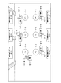
図6は、歩行者130(移動体)を物体検知センサ2等が検知した順の例を示す図である。図6に例示する画像は、複数の物体検知センサ2が送信したカメラ画像に基づく画像である。図6に例示する画像は、表示部40に表示される。
FIG. 6 is a diagram showing an example of the order in which the
歩行者130は、位置検出装置3が位置検出モードで動作する場合、経路6に沿って室内を移動する。図6では、歩行者の位置は、図5に示す経路6に沿って、時系列で歩行者130−1〜130−6の順に変化する。
The pedestrian 130 moves inside the room along the
検知順表示画像8は、歩行者130の検知順「1番〜6番のいずれか」を表す画像である。例えば、検知順表示画像8−1は、物体検知センサ2−6が時刻t1における歩行者130−1を検知したことに基づいて、歩行者130の検知順「1番」を表す。例えば、検知順表示画像8−3は、物体検知センサ2−3が時刻t1よりも後の時刻t6における歩行者130−6を検知したことに基づいて、歩行者130の検知順「6番」を表す。 The detection order display image 8 is an image representing the detection order of the pedestrian 130 "one of the first to sixth". For example, the detection order display image 8-1 represents the detection order “first” of the pedestrian 130 based on that the object detection sensor 2-6 detects the pedestrian 130-1 at the time t1. For example, the detection order display image 8-3 is based on that the object detection sensor 2-3 detects the pedestrian 130-6 at the time t6 after the time t1 and the detection order “6th” of the pedestrian 130. Represents.
図7は、ヘルメットを身に着けた歩行者131(移動体)の検知順の例を示す図である。図7に例示する画像は、複数の物体検知センサ2が送信したカメラ画像に基づく画像である。図7に例示する画像は、表示部40に表示される。
FIG. 7 is a diagram illustrating an example of a detection order of a pedestrian 131 (moving body) wearing a helmet. The image illustrated in FIG. 7 is an image based on the camera images transmitted by the plurality of
歩行者131は、位置検出装置3が位置検出モードで動作する場合、図5に示す経路6に沿って室内を移動する。図7では、歩行者の位置は、図5に示す経路6に沿って、時系列で歩行者131−1〜131−6の順に変化する。位置検出部35は、歩行者131が身に着けているヘルメットの色や模様等に基づいて、歩行者131と他の歩行者とを識別することができる。
The pedestrian 131 moves inside the room along the
検知順表示画像8は、歩行者131の検知順「1番〜6番のいずれか」を表す画像である。例えば、検知順表示画像8−1は、物体検知センサ2−6が時刻t1における歩行者131−1を検知したことに基づいて、歩行者131の検知順「1番」を表す。例えば、検知順表示画像8−3は、物体検知センサ2−3が時刻t1よりも後の時刻t6における歩行者131−6を検知したことに基づいて、歩行者131の検知順「6番」を表す。 The detection order display image 8 is an image showing the detection order of the pedestrian 131 “any one of Nos. 1 to 6”. For example, the detection order display image 8-1 represents the detection order “first” of the pedestrian 131 based on that the object detection sensor 2-6 detects the pedestrian 131-1 at the time t1. For example, the detection order display image 8-3 is based on that the object detection sensor 2-3 detects the pedestrian 131-6 at the time t6 after the time t1, and the detection order “6th” of the pedestrian 131. Represents.
位置検出部35(リンク部)は、物体検知センサ2が歩行者131を検知した順と歩行者131が物体検知センサ2の検知範囲を通過した順との対応関係に基づいて、物体検知センサ2の位置を物体検知センサ2ごとに検出する。
The position detection unit 35 (link unit) uses the
図8は、物体検知センサ2の位置検出結果情報の第1例を示す図である。図8では、歩行者の検知順と、物体検知センサ2の識別情報と、歩行者が物体検知センサ2の検知範囲を通過した順(歩行者の通過順)と、物体検知センサ2の位置とが対応付けられる。
FIG. 8 is a diagram showing a first example of the position detection result information of the
位置検出部35は、歩行者131を検知した物体検知センサ2の識別情報を、歩行者131の検知順に対応付けて、位置検出結果情報に登録する。例えば、位置検出部35は、歩行者131を1番目に検知した物体検知センサ2の識別情報「2−6」を、歩行者131の検知順「1番」に対応付けて、位置検出結果情報に登録する。例えば、位置検出部35は、歩行者131を6番目に検知した物体検知センサ2の識別情報「2−3」を、歩行者131の検知順「6番」に対応付けて、位置検出結果情報に登録する。
The
位置検出部35は、歩行者131が物体検知センサ2の検知範囲を通過した順(通過順)に対応付けて、物体検知センサ2の位置情報を、操作部31又は登録部33から取得する。位置検出部35は、歩行者131の検知順と歩行者131の通過順とが等しくなるように、物体検知センサ2の識別情報と物体検知センサ2の位置情報とを対応付ける。
The
例えば、位置検出部35は、歩行者の通過順「1番」に対応付けられた物体検知センサ2の識別情報「2−6」と、歩行者の検知順「1番」に対応付けられた物体検知センサ2−6の位置「P6」とを対応付ける。例えば、位置検出部35は、歩行者の通過順「6番」に対応付けられた物体検知センサ2の識別情報「2−3」と、歩行者の検知順「6番」に対応付けられた物体検知センサ2−3の位置「P3」とを対応付ける。
For example, the
これにより、位置検出部35は、物体検知センサ2の位置を物体検知センサ2ごとに検出することができる。例えば、位置検出部35は、識別情報「2−6」が割り当てられている物体検知センサ2−6が室内における位置「P6」に設置されていることを、検出することができる。例えば、位置検出部35は、識別情報「2−3」が割り当てられている物体検知センサ2−3が室内における位置「P3」に設置されていることを、検出することができる。
Accordingly, the
位置検出部35(リンク部)は、物体検知センサ2が歩行者131を検知した時刻と歩行者131が物体検知センサ2の検知範囲を通過した時刻との対応関係に基づいて、物体検知センサ2の位置を物体検知センサ2ごとに検出してもよい。
The position detection unit 35 (link unit) uses the
図9は、物体検知センサ2の位置検出結果情報の第2例を示す図である。図9では、歩行者の検知時刻と、物体検知センサ2の識別情報と、歩行者が物体検知センサ2の検知範囲を通過した時刻(歩行者の通過時刻)と、物体検知センサ2の位置とが対応付けられる。歩行者の通過時刻は、経路6に定められる。
FIG. 9 is a diagram showing a second example of the position detection result information of the
位置検出部35は、歩行者131を検知した物体検知センサ2の識別情報を、歩行者131の検知時刻に対応付けて、位置検出結果情報に登録する。例えば、位置検出部35は、歩行者131を時刻t1に検知した物体検知センサ2の識別情報「2−6」を、歩行者131の検知時刻「t1」に対応付けて、位置検出結果情報に登録する。例えば、位置検出部35は、歩行者131を時刻t6に検知した物体検知センサ2の識別情報「2−3」を、歩行者131の検知時刻「t6」に対応付けて、位置検出結果情報に登録する。
The
位置検出部35は、歩行者131が物体検知センサ2の検知範囲を通過した時刻(通過時刻)に対応付けて、物体検知センサ2の位置情報を、操作部31又は登録部33から取得する。位置検出部35は、歩行者131の検知時刻と歩行者131の通過時刻とが等しくなるように、物体検知センサ2の識別情報と物体検知センサ2の位置情報とを対応付ける。
The
例えば、位置検出部35は、歩行者の通過時刻「t1」に対応付けられた物体検知センサ2の識別情報「2−6」と、歩行者の検知時刻「t1」に対応付けられた物体検知センサ2−6の位置「P6」とを対応付ける。例えば、位置検出部35は、歩行者の通過時刻「t6」に対応付けられた物体検知センサ2の識別情報「2−3」と、歩行者の検知時刻「t6」に対応付けられた物体検知センサ2−3の位置「P3」とを対応付ける。
For example, the
これにより、位置検出部35は、物体検知センサ2の位置を物体検知センサ2ごとに検出することができる。例えば、位置検出部35は、識別情報「2−6」が割り当てられている物体検知センサ2−6が室内における位置「P6」に設置されていることを、検出することができる。例えば、位置検出部35は、識別情報「2−3」が割り当てられている物体検知センサ2−3が室内における位置「P3」に設置されていることを、検出することができる。
Accordingly, the
図1に戻り、位置検出装置3の構成の説明を続ける。補正部36は、物体検知センサ2のカメラ部20の魚眼レンズによるカメラ画像(以下、「歪補正前カメラ画像」という。)の歪みを補正する。補正部36は、歪みを補正した後のカメラ画像(以下、「歪補正後カメラ画像」という。)を、回転検出部37及び表示制御部38に送信する。
Returning to FIG. 1, the description of the configuration of the position detection device 3 will be continued. The
物体検知センサ2が天井に設置された際、基準に対して物体検知センサ2の向きに回転ずれ量が生じる場合がある。補正部36は、物体検知センサ2の向き又はカメラ画像の回転ずれ量を表す情報を、物体検知センサ2ごとに回転検出部37から取得する。補正部36は、回転ずれ量に基づいて、歪補正後カメラ画像の回転ずれ量を補正する。補正部36は、回転ずれ量が補正された歪補正後カメラ画像を、表示制御部38に送信する。
When the
回転検出部37は、カメラ画像を取得する。回転検出部37は、設置された物体検知センサ2の向き又はカメラ画像の回転ずれ量を、カメラ画像と正解データとの比較結果に基づいて検出する。回転検出部37は、物体検知センサ2の向き又はカメラ画像の回転ずれ量を表す情報を、補正部36及び表示制御部38に送信する。
The
回転検出部37は、設置された物体検知センサ2の回転ずれ量を表す情報を、音声で出力してもよい。回転検出部37は、回転ずれ量が閾値以上である物体検知センサ2の検知範囲を歩行者131が通過した場合、回転ずれ量が閾値以上である物体検知センサ2の検知範囲を歩行者131が通過したことを表す情報を、音声等で作業者等に通知してもよい。回転検出部37は、回転ずれ量が閾値以上である物体検知センサ2の位置と歩行者131の位置との間の距離を、音声等で作業者等に通知してもよい。回転検出部37は、歩行者131の位置を原点として、回転ずれ量が閾値以上である物体検知センサ2の位置の方向を、音声等で作業者等に通知してもよい。
The
回転検出部37は、カメラ画像上の第1領域及び第2領域と歩行者の移動の経路との対応関係に基づいて、設置された物体検知センサ2の向き又はカメラ画像の回転ずれ量を検出する。例えば、回転検出部37は、カメラ画像を分割する複数の領域と歩行者の移動の経路との対応関係に基づいて、設置された物体検知センサ2の向き又はカメラ画像の回転ずれ量を検出する。
The
図10は、回転ずれ量が少ない歪補正後カメラ画像140−2における歩行者131の移動の経路の例を示す図である。歪補正後カメラ画像140−2では、歩行者の位置は、図5に示す経路6に沿って、時系列で歩行者131−5−1、131−5−2、131−5−3の順に変化する。なお、歩行者131は、図5に示す経路6におおむね沿って移動しているのであれば、歪補正後カメラ画像140−2において直進していなくてもよい。
FIG. 10 is a diagram illustrating an example of a movement path of the pedestrian 131 in the distortion-corrected camera image 140-2 with a small amount of rotation deviation. In the distortion-corrected camera image 140-2, the positions of the pedestrians are the pedestrians 131-5-1, 131-5-2, 131-5-3 in chronological order along the
図11は、回転ずれ量の検出の第1例を示す図である。図11では、図10に示す歪補正後カメラ画像140−2は、領域120−1〜120−9に分割されている。図11では、画像認識部23又は画像認識部42が歪補正後カメラ画像140−2の歩行者131を最初に検知した領域(進入領域)は、領域120−4である。
FIG. 11 is a diagram showing a first example of detecting the amount of rotation deviation. In FIG. 11, the distortion-corrected camera image 140-2 shown in FIG. 10 is divided into regions 120-1 to 120-9. In FIG. 11, the region (entry region) in which the image recognition unit 23 or the
なお、画像認識部23又は画像認識部42は、隣り合う領域120にまたがって歩行者131を検出した場合、隣り合う領域120のいずれかで歩行者131を検知した領域120を選択してもよい。
When the image recognizing unit 23 or the
画像認識部23又は画像認識部42が歪補正後カメラ画像140−2において歩行者131を最初に検知した領域は、検知に時間がかかる等の理由で、領域120−5でもよい。画像認識部23又は画像認識部42が歪補正後カメラ画像140−2において歩行者131を最後に検知した領域(退出領域)は、領域120−6である。
The region in which the pedestrian 131 is first detected by the image recognition unit 23 or the
回転検出部37は、歪補正後カメラ画像140−2における歩行者131の最初検知推定領域である領域120−4を表す情報を、登録部33又は記憶部39から取得する。回転検出部37は、歪補正後カメラ画像140−2における歩行者131の最後検知推定領域である領域120−6を表す情報を、登録部33又は記憶部39から取得する。
The
回転検出部37は、歪補正後カメラ画像140−2において歩行者131を最初に検知した領域と最初検知推定領域である領域120−4とが同じ領域であるか否かを、正解データに基づいて判定する。回転検出部37は、画像認識部23又は画像認識部42が歪補正後カメラ画像140−2において歩行者131を最後に検知した領域と最後検知推定領域である領域120−6とが同じ領域であるか否かを、正解データに基づいて判定する。
The
図11では、回転検出部37は、歩行者131を最初に検知した領域120と歩行者131の最初検知推定領域とが同じ領域であり、歩行者131を最後に検知した領域120と歩行者131の最後検知推定領域とが同じ領域であるため、設置された物体検知センサ2の向き又はカメラ画像の回転ずれ量が少ないと判定する。
In FIG. 11, in the
図12は、回転ずれ量が閾値以上である歪補正後カメラ画像140aにおける歩行者131の移動の経路の例を示す図である。歪補正後カメラ画像140a−2では、歩行者の位置は、図5に示す経路6に沿って、時系列で歩行者131−5−1、131−5−2、131−5−3の順に変化する。なお、歩行者131は、図5に示す経路6におおむね沿って移動しているのであれば、歪補正後カメラ画像140a−2において直進していなくてもよい。
FIG. 12 is a diagram showing an example of the path of movement of the pedestrian 131 in the
図13は、回転ずれ量の検出の第2例を示す図である。図13では、図10に示す歪補正後カメラ画像140a−2は、領域120−1〜120−9に分割されている。歪補正後カメラ画像140a−2において、画像認識部23又は画像認識部42が歩行者131を最初に検知した領域(進入領域)は、領域120−1である。
FIG. 13 is a diagram showing a second example of detecting the amount of rotation deviation. In FIG. 13, the distortion-corrected
画像認識部23又は画像認識部42が歪補正後カメラ画像140a−2において歩行者131を最初に検知した領域は、検知に時間がかかる等の理由で、領域120−5でもよい。画像認識部23又は画像認識部42が歪補正後カメラ画像140a−2において歩行者131を最後に検知した領域(退出領域)は、領域120−9である。
The area in which the image recognizing unit 23 or the
回転検出部37は、歪補正後カメラ画像140a−2において歩行者131を最初に検知した領域と最初検知推定領域である領域120−4とが同じ領域であるか否かを判定する。回転検出部37は、画像認識部23又は画像認識部42が歪補正後カメラ画像140a−2において歩行者131を最後に検知した領域と最後検知推定領域である領域120−6とが同じ領域であるか否かを判定する。
The
図13では、回転検出部37は、歩行者131を最初に検知した領域120と歩行者131を最後に検知した領域120とのうち少なくとも一方が所定領域でない場合、設置された物体検知センサ2の回転ずれ量が閾値以上であると判定する。回転検出部37は、歩行者131を最初に検知した領域120と歩行者131の最初検知推定領域とが異なる領域であるため、設置された物体検知センサ2の向き又はカメラ画像の回転ずれ量が閾値以上であると判定する。回転検出部37は、歩行者131を最後に検知した領域120と歩行者131の最後検知推定領域とが異なる領域であるため、設置された物体検知センサ2の向き又はカメラ画像の回転ずれ量が閾値以上であると判定してもよい。
In FIG. 13, when at least one of the area 120 in which the pedestrian 131 is first detected and the area 120 in which the pedestrian 131 is finally detected is not a predetermined area, the
回転検出部37は、カメラ画像に定められた座標軸と歩行者の移動の経路とが成す角度に基づいて、設置された物体検知センサ2の向き又はカメラ画像の回転ずれ量を検出してもよい。なお、歩行者131は、カメラ画像に定められた座標軸と歩行者131の移動の経路6とが成す角度が一定になるように経路6に沿って移動してもよい。この場合、移動体の経路の方向(基準方向)を表す角度の正解データは、予め登録される。
The
図14は、回転ずれ量の検出の第3例を示す図である。図14に示す歪補正後カメラ画像140−2には、XY座標軸(2次元の座標軸)が定められている。図14では、X軸は、物体検知センサ2の回転ずれ量が少ない場合における経路6の基準方向(歩行者の移動の基準方向)を示す。
FIG. 14 is a diagram showing a third example of detecting the amount of rotation deviation. An XY coordinate axis (two-dimensional coordinate axis) is defined in the distortion-corrected camera image 140-2 shown in FIG. In FIG. 14, the X axis indicates the reference direction of the route 6 (the reference direction of movement of a pedestrian) when the amount of rotation deviation of the
画像認識部23又は画像認識部42が歪補正後カメラ画像140−2において歩行者131を最初に検知した位置は、歩行者131−5−1の位置である。画像認識部23又は画像認識部42が歪補正後カメラ画像140−2において歩行者131を最後に検知した位置は、歩行者131−5−3の位置である。
The position where the image recognition unit 23 or the
破線200は、歪補正後カメラ画像140−2において歩行者131を最初に検知した位置から歩行者131を最後に検知した位置までを結ぶ破線である。したがって、破線200は、歪補正後カメラ画像140−2における歩行者131の移動の方向を表す。
A
図14では、回転検出部37は、物体検知センサ2の回転ずれ量が少ない場合における経路6の方向(歩行者の移動の基準方向)と破線200の方向(歩行者の移動の方向)とが一致しているので、設置された物体検知センサ2の向き又はカメラ画像の回転ずれ量が少ないと判定する。
In FIG. 14, the
図15は、回転ずれ量の検出の第4例を示す図である。図15に示す歪補正後カメラ画像140a−2には、XY座標軸(2次元の座標軸)が定められている。図15では、X軸は、物体検知センサ2の回転ずれ量が少ない(閾値未満である)場合における経路6の基準方向(歩行者の移動の基準方向)を示す。
FIG. 15 is a diagram showing a fourth example of detecting the amount of rotation deviation. An XY coordinate axis (two-dimensional coordinate axis) is defined in the distortion-corrected
画像認識部23又は画像認識部42が歪補正後カメラ画像140a−2において歩行者131を最初に検知した位置は、歩行者131−5−1の位置である。画像認識部23又は画像認識部42が歪補正後カメラ画像140a−2において歩行者131を最後に検知した位置は、歩行者131−5−3の位置である。
The position where the image recognizing unit 23 or the
破線200は、歪補正後カメラ画像140a−2において歩行者131を最初に検知した位置から歩行者131を最後に検知した位置までを結ぶ破線である。したがって、破線200は、歪補正後カメラ画像140a−2における歩行者131の移動の方向を表す。図15では、破線200は、X軸に対して(−45度)に傾いている。
A
図15では、回転検出部37は、歪補正後カメラ画像140a−2における経路6を表す基準方向(X軸)と破線200の方向(歩行者131の移動の方向)とが一致していないので、設置された物体検知センサ2の向き又はカメラ画像の回転ずれ量が閾値以上であると判定する。回転検出部37は、物体検知センサ2の向き又はカメラ画像の回転ずれ量(−45度)を表す情報を、補正部36及び表示制御部38に送信する。
In the
表示制御部38は、マップ5、経路6、位置表示画像7、検知順表示画像8、回転ずれ量の有無、回転ずれ量、歪補正前カメラ画像、歪補正後カメラ画像、検知情報及びこれらの組み合わせを、表示部40に表示する。
The
図16は、マップ5の表示と歪補正前カメラ画像141の一覧表示との例を示す図である。表示制御部38は、マップ5と歪補正前カメラ画像141の一覧とを、表示部40に表示する。表示制御部38は、歪補正前カメラ画像141−1〜141−6を、物体検知センサ2の位置に対応付けて、表示部40の画面に配列する。
FIG. 16 is a diagram showing an example of the display of the
図17は、マップ5の表示と歪補正前カメラ画像141の巡回表示との例を示す図である。表示制御部38は、操作部31が操作された場合、歪補正前カメラ画像141−1〜141−5のうちから歪補正前カメラ画像141を一定時間ごとに選択する。図17では、表示制御部38は、歪補正前カメラ画像141−4及び歪補正前カメラ画像141−5を選択している。表示制御部38は、選択する歪補正前カメラ画像141を切り替えながら、選択された歪補正前カメラ画像141を巡回表示する。
FIG. 17 is a diagram showing an example of the display of the
図18は、マップ5の表示と歪補正前カメラ画像141の選択表示との例を示す図である。表示制御部38は、操作部31が操作された場合、歪補正前カメラ画像141−1〜141−5のうちから歪補正前カメラ画像141を操作に応じて選択する。図18では、表示制御部38は、操作部31がクリック操作されて位置表示画像7−2が選択されたことによって、位置表示画像7−2に対応付けられた物体検知センサ2−2の歪補正前カメラ画像141−2を選択している。表示制御部38は、選択された歪補正前カメラ画像141−2を拡大表示する。
FIG. 18 is a diagram showing an example of the display of the
図19は、マップ5の表示とマップ5に重畳した歪補正前カメラ画像141の表示との例を示す図である。表示制御部38は、マップ5と歪補正前カメラ画像141の一覧とを、表示部40に表示する。表示制御部38は、歪補正前カメラ画像141−1〜141−6を、物体検知センサ2の位置に基づく位置表示画像7−1〜7−6に対応付けて、表示部40の画面に配列する。
FIG. 19 is a diagram showing an example of display of the
図20は、マップ5の表示とマップ5に重畳した歪補正後カメラ画像140の一覧表示との第1例を示す図である。表示制御部38は、マップ5と歪補正後カメラ画像140の一覧とを、表示部40に表示する。表示制御部38は、歪補正後カメラ画像140−1〜140−6を、物体検知センサ2の位置に基づく位置表示画像7−1〜7−6に対応付けて、表示部40の画面に配列する。
FIG. 20 is a diagram showing a first example of the display of the
図21は、マップ5の表示とマップ5に重畳した歪補正後カメラ画像140の一覧表示との第2例を示す図である。表示制御部38は、複数の歪補正後カメラ画像140を互いに隣接するように配列することによって、室内の鳥瞰図を生成する(非特許文献2参照)。表示制御部38は、マップ5と鳥瞰図とを、表示部40に表示する。
FIG. 21 is a diagram showing a second example of the display of the
図22は、マップ5の表示とマップ5に重畳した歪補正後カメラ画像140の一覧表示との第3例を示す図である。表示制御部38は、歪補正後カメラ画像140a−2の回転ずれ量が補正された歪補正後カメラ画像140−2を、補正部36から取得する。表示制御部38は、回転ずれ量が補正された歪補正後カメラ画像140−2を含む複数の歪補正後カメラ画像140を互いに隣接するように配列することによって、室内の鳥瞰図を生成する。表示制御部38は、マップ5と鳥瞰図とを、表示部40に表示する。
FIG. 22 is a diagram showing a third example of the display of the
表示制御部38は、双方向のユーザインタフェースであるインタラクティブUI(Interactive User Interface)に基づく動作を実行してもよい。例えば、表示制御部38は、表示部40に表示されたカメラ画像を作業員が操作部31を用いてクリック操作した場合、位置検出処理をやり直すことを命令する信号を、位置検出部35に送信する。位置検出部35は、位置検出処理をやり直すことを命令する信号を取得した場合、位置検出処理をやり直す。位置検出部35は、歩行者130が室内を移動した後に位置検出処理をやり直してもよいし、歩行者130が室内を移動している途中で位置検出処理をやり直してもよい。
The
なお、表示制御部38は、図19から図22までに示す図を、表示部40に常時表示してもよいし、物体検知センサ2が歩行者131を検知したタイミングで表示部40に表示してもよい。表示制御部38は、歩行者131の検知が終了する前では、最新のカメラ画像を表示部40に表示してもよい。表示制御部38は、歩行者の検知が終了した後では、カメラ画像のベストショットを表示部40に表示してもよい。表示制御部38は、歩行者の検知開始のタイミングで、カメラ画像を表示部40にポップアップ表示してもよい。表示制御部38は、歪補正前カメラ画像の歪みを補正してもよい。表示制御部38は、回転ずれ量に基づいて、歪補正後カメラ画像の回転ずれ量を補正してもよい。
Note that the
図1に戻り、位置検出装置3の構成の説明を続ける。記憶部39は、磁気ハードディスク装置や半導体記憶装置等の不揮発性の記憶媒体(非一時的な記録媒体)を有する記憶装置を用いて構成される。記憶部39は、特定情報と、検知情報と、位置検出プログラムと、位置検出結果情報とを記憶する。
Returning to FIG. 1, the description of the configuration of the position detection device 3 will be continued. The
表示部40は、液晶ディスプレイ等の表示デバイスである。表示部40は、マップ5、経路6、位置表示画像7、検知順表示画像8、回転ずれ量の有無、回転ずれ量、歪補正前カメラ画像、歪補正後カメラ画像、検知情報及びこれらの組み合わせを表示する。表示部40は、歪補正前カメラ画像の歪みを補正してもよい。表示部40は、回転ずれ量に基づいて、歪補正後カメラ画像の回転ずれ量を補正してもよい。
The
バス41は、位置検出装置3の各部の間でデータを伝送する伝送路である。
The
画像認識部23は、物体検知センサ2の画像認識部23が実行していた画像認識等の画像処理を、物体検知センサ2の代わりに実行する。
The image recognition unit 23 performs the image processing such as image recognition performed by the image recognition unit 23 of the
次に、位置検出システム1の動作を説明する。
図23は、物体検知センサ2の位置を検出する動作の例を示すフローチャートである。通信部30は、歩行者を検知した複数の物体検知センサ2から、物体検知センサ2の識別情報を取得する(ステップS101)。位置検出部35は、経路6に沿って移動した歩行者を検知した結果に基づいて、物体検知センサ2の識別情報と物体検知センサ2の位置とを対応付ける(ステップS102)。
Next, the operation of the position detection system 1 will be described.
FIG. 23 is a flowchart showing an example of the operation of detecting the position of the
図24は、物体検知センサ2の回転ずれ量を検出する動作の例を示すフローチャートである。通信部30は、経路6に沿って移動した歩行者を検知した結果に基づくカメラ画像を、物体検知センサ2から取得する(ステップS201)。回転検出部37は、カメラ画像において歩行者を最初に検知した位置とカメラ画像において歩行者を最後に検知した位置とに基づいて、物体検知センサ2の回転ずれ量を検出する(ステップS202)。
FIG. 24 is a flowchart showing an example of the operation of detecting the amount of rotation deviation of the
以上のように、実施形態の位置検出装置3は、登録部33と、通信部30と、位置検出部35とを持つ。複数の物体検知センサ2は、複数の位置に設置されている。登録部33は、経路6を記憶部39に登録する。通信部30は、登録された経路6に沿って移動した歩行者を複数の物体検知センサ2が検知した結果を表す検知情報と、物体検知センサ2の識別情報とを取得する。位置検出部35は、歩行者が複数の物体検知センサ2の検知範囲を通過した結果と検知情報とに基づいて、物体検知センサ2の識別情報と物体検知センサ2の位置とを対応付けることによって、物体検知センサ2の位置を検出する。
As described above, the position detection device 3 of the embodiment has the
この構成によって、位置検出部35は、歩行者が複数の物体検知センサ2の検知範囲を通過した結果と検知情報とに基づいて、物体検知センサ2の識別情報と物体検知センサ2の位置とを対応付ける。これによって、実施形態の位置検出装置3は、複数の物体検知センサ2の位置を物体検知センサ2ごとに検出することができる。
With this configuration, the
実施形態の位置検出部35は、複数の物体検知センサ2が歩行者を検知した順と歩行者が複数の物体検知センサ2の検知範囲を通過した順とが等しくなるように、物体検知センサ2の識別情報と物体検知センサ2の位置とを対応付けてもよい。実施形態の位置検出部35は、複数の物体検知センサが歩行者を検知した時刻と歩行者が複数の物体検知センサの検知範囲を通過した時刻とが等しくなるように、物体検知センサ2の識別情報と物体検知センサ2の位置とを対応付けてもよい。
The
以上のように、実施形態の位置検出装置3は、登録部33と、回転検出部37とを持つ。登録部33は、移動する歩行者の経路6に関する正解データと経路6とを、記憶部39に登録する。回転検出部37は、登録された経路6に沿って移動した歩行者を複数の物体検知センサ2が検知した結果を表す検知情報と正解データとの比較結果に基づいて、予め定められた向きに対する物体検知センサ2の回転ずれ量を検出する。
As described above, the position detection device 3 according to the embodiment has the
この構成によって、回転検出部37は、登録された経路6に沿って移動した歩行者を複数の物体検知センサ2が検知した結果を表す検知情報と正解データとの比較結果に基づいて、予め定められた向きに対する物体検知センサ2の回転ずれ量を検出する。これによって、実施形態の位置検出装置3は、複数の物体検知センサ2の回転ずれ量を物体検知センサ2ごとに検出することができる。
With this configuration, the
実施形態の回転検出部37は、物体検知センサ2が歩行者を最初に検知したカメラ画像上の領域120と、物体検知センサ2が歩行者を最後に検知した領域120と、正解データとの比較結果に基づいて、物体検知センサ2の回転ずれ量を検出してもよい。この場合、領域という粗い精度(単位)で移動体の位置を比較しているので、画像における歩行者等の移動体の位置の精度は、画素、領域又は3次元座標等のどのような精度でもよい。実施形態の回転検出部37は、カメラ画像上の歩行者の移動の方向と、カメラ画像上の経路6の方向(基準方向)を表す正解データとの比較結果に基づいて、物体検知センサ2の回転ずれ量の角度を検出してもよい。
The
以上述べた少なくともひとつの実施形態によれば、登録された前記経路に沿って移動した前記物体を前記複数の物体検知センサが検知した結果を表す検知情報と正解データとの比較結果に基づいて物体検知センサの回転ずれ量を検出する回転検出部を持つことにより、複数の物体検知センサの回転ずれ量を物体検知センサごとに検出することができる。 According to at least one embodiment described above, an object based on the comparison result of the detection information and the correct answer data indicating the result of the plurality of object detection sensors detecting the object that has moved along the registered route. By providing the rotation detection unit that detects the rotation deviation amount of the detection sensor, the rotation deviation amounts of the plurality of object detection sensors can be detected for each object detection sensor.
以上、本発明のいくつかの実施形態を説明したが、これらの実施形態は、例として提示したものであり、発明の範囲を限定することは意図していない。これら実施形態は、その他の様々な形態で実施されることが可能であり、発明の要旨を逸脱しない範囲で、種々の省略、置き換え、変更を行うことができる。これら実施形態やその変形は、発明の範囲や要旨に含まれると同様に、特許請求の範囲に記載された発明とその均等の範囲に含まれるものである。 Although some embodiments of the present invention have been described above, these embodiments are presented as examples and are not intended to limit the scope of the invention. These embodiments can be implemented in various other forms, and various omissions, replacements, and changes can be made without departing from the spirit of the invention. The embodiments and their modifications are included in the scope of the invention and the scope thereof, and are included in the invention described in the claims and the scope of equivalents thereof.
1…位置検出システム、2…物体検知センサ、3…位置検出装置、4…通信回線、5…マップ、6…経路、7…位置表示画像、8…検知順表示画像、20…カメラ部、21…操作部、22…記憶部、23…画像認識部、24…ID設定部、25…通信部、26…バス、30…通信部、31…操作部、32…マップ設定部、33…登録部、34…指示部、35…位置検出部、36…補正部、37…回転検出部、38…表示制御部、39…記憶部、40…表示部、41…バス、42…画像認識部、100…マスク領域、110…カメラ画像領域、120…領域、130…歩行者、131…歩行者、140…歪補正後カメラ画像、141…歪補正前カメラ画像、200…破線 DESCRIPTION OF SYMBOLS 1 ... Position detection system, 2 ... Object detection sensor, 3 ... Position detection device, 4 ... Communication line, 5 ... Map, 6 ... Route, 7 ... Position display image, 8 ... Detection order display image, 20 ... Camera part, 21 ... operation unit, 22 ... storage unit, 23 ... image recognition unit, 24 ... ID setting unit, 25 ... communication unit, 26 ... bus, 30 ... communication unit, 31 ... operation unit, 32 ... map setting unit, 33 ... registration unit , 34 ... Instructing section, 35 ... Position detecting section, 36 ... Correction section, 37 ... Rotation detecting section, 38 ... Display control section, 39 ... Storage section, 40 ... Display section, 41 ... Bus, 42 ... Image recognition section, 100 ... mask area, 110 ... camera image area, 120 ... area, 130 ... pedestrian, 131 ... pedestrian, 140 ... camera image after distortion correction, 141 ... camera image before distortion correction, 200 ... broken line
Claims (14)
移動する前記物体の経路に関する正解データと前記経路とを登録する登録部と、
登録された前記経路に沿って移動した前記物体を前記複数の物体検知センサが検知した結果を表す検知情報と前記正解データとの比較結果に基づいて、予め定められた向きに対する前記物体検知センサの回転ずれ量を検出する回転検出部と、
を備える回転ずれ量検出装置。 A plurality of object detection sensors for detecting an object are installed at a plurality of positions, a rotation deviation amount detection device for detecting a rotation deviation amount of the object detection sensor,
A registration unit that registers the correct answer data regarding the path of the moving object and the path;
Based on the result of comparison between the correct information and the detection information representing the result of detection of the object moved along the registered path by the plurality of object detection sensors, the object detection sensor of the predetermined orientation A rotation detector that detects the amount of rotation deviation,
Rotational deviation amount detection device comprising:
をさらに備え、
前記回転検出部は、指定された前記物体を検知したことを前記画像認識部が特定した場合、指定された前記物体の前記検知情報に基づいて前記複数の物体検知センサの回転ずれ量を前記物体検知センサごとに検出する、請求項1から請求項4のいずれか一項に記載の回転ずれ量検出装置。 An image recognition unit is further provided for specifying whether or not the specified object is detected by image recognition,
When the image recognition unit identifies that the rotation detection unit has detected the designated object, the rotation detection unit determines the amount of rotation deviation of the plurality of object detection sensors based on the detection information of the designated object. The rotation deviation amount detection device according to any one of claims 1 to 4, which detects each of the detection sensors.
をさらに備える、請求項1から請求項5のいずれか一項に記載の回転ずれ量検出装置。 The parameter used for detecting the object is changed depending on whether the rotation detection unit detects the rotation deviation amount of the object detection sensor or when the rotation detection unit does not detect the rotation deviation amount of the object detection sensor. 6. The instruction unit according to claim 1, further comprising: an instruction unit for instructing the object detection sensor of an operation mode and the parameter according to whether or not to detect a rotation deviation amount of the detection sensor. Rotational deviation amount detection device.
をさらに備える、請求項1から請求項6のいずれか一項に記載の回転ずれ量検出装置。 The rotation deviation amount detection according to any one of claims 1 to 6, further comprising: a display control unit configured to arrange an image based on the detection information on a screen of a display unit in association with a position of the object detection sensor. apparatus.
をさらに備え、
前記表示制御部は、前記歪みが補正された画像を前記表示部の画面に表示する、請求項7に記載の回転ずれ量検出装置。 Further comprising a correction unit for correcting image distortion based on the detection information,
The rotation deviation amount detection device according to claim 7, wherein the display control unit displays the image in which the distortion is corrected on a screen of the display unit.
指定された前記物体を検知したか否かを画像認識によって特定するための情報である特定情報を取得する取得部と、
自物体検知センサの回転ずれ量を他の装置が検出する場合と自物体検知センサの回転ずれ量を前記他の装置が検出しない場合とで前記物体の検知に用いるパラメータを変更し、指定された前記物体を検知したか否かを画像認識によって前記特定情報に基づいて特定する画像認識部と、
登録された経路に沿って移動した前記物体を検知した結果を表す検知情報と自物体検知センサの識別情報とを前記他の装置に送信する送信部と、
を備える物体検知センサ。 A sensor that detects an object,
An acquisition unit that acquires specific information that is information for specifying whether or not the specified object is detected by image recognition,
The parameters used to detect the object are changed and designated depending on whether the rotation deviation amount of the self-object detection sensor is detected by another device or when the rotation deviation amount of the self-object detection sensor is not detected by the other device. An image recognition unit that specifies whether or not the object is detected based on the specific information by image recognition,
A transmission unit that transmits the detection information indicating the result of detecting the object that has moved along the registered path and the identification information of the self-object detection sensor to the other device,
An object detection sensor including.
移動する前記物体の経路に関する正解データと前記経路とを登録する登録部と、
登録された前記経路に沿って移動した前記物体を前記複数の物体検知センサが検知した結果を表す検知情報と前記正解データとの比較結果に基づいて、予め定められた向きに対する前記物体検知センサの回転ずれ量を検出する回転検出部と、
を備える回転ずれ量検出システム。 A plurality of object detection sensors installed in a plurality of positions to detect an object,
A registration unit that registers the correct answer data regarding the path of the moving object and the path;
Based on the result of comparison between the correct information and the detection information representing the result of detection of the object moved along the registered path by the plurality of object detection sensors, the object detection sensor of the predetermined orientation A rotation detector that detects the amount of rotation deviation,
A rotation deviation amount detection system including.
移動する前記物体の経路に関する正解データと前記経路とを登録するステップと、
登録された前記経路に沿って移動した前記物体を前記複数の物体検知センサが検知した結果を表す検知情報とと前記正解データとの比較結果に基づいて、予め定められた向きに対する前記物体検知センサの回転ずれ量を検出するステップと、
を含む回転ずれ量検出方法。 A plurality of object detection sensors for detecting an object are installed at a plurality of positions, a rotation deviation amount detection method executed by a rotation deviation amount detection device for detecting a rotation deviation amount of the object detection sensor,
Registering the correct answer data regarding the path of the moving object and the path,
The object detection sensor for a predetermined direction based on a comparison result of detection information indicating a result of detection of the object moving along the registered path by the plurality of object detection sensors and the correct answer data. Detecting the amount of rotation deviation of
A method for detecting the amount of rotation deviation including.
移動する前記物体の経路に関する正解データと前記経路とを登録する手順と、
登録された前記経路に沿って移動した前記物体を前記複数の物体検知センサが検知した結果を表す検知情報と前記正解データとの比較結果に基づいて、予め定められた向きに対する前記物体検知センサの回転ずれ量を検出する手順と、
を実行させるための回転ずれ量検出プログラム。 A plurality of object detection sensors for detecting an object are installed at a plurality of positions, the computer of the rotation deviation amount detection device for detecting the rotation deviation amount of the object detection sensor,
A step of registering the correct answer data regarding the path of the moving object and the path;
Based on the result of comparison between the correct information and the detection information representing the result of detection of the object moved along the registered path by the plurality of object detection sensors, the object detection sensor of the predetermined orientation Procedure to detect the amount of rotation deviation,
A rotation deviation amount detection program for executing.
Priority Applications (2)
| Application Number | Priority Date | Filing Date | Title |
|---|---|---|---|
| JP2017000127A JP6696693B2 (en) | 2017-01-04 | 2017-01-04 | Rotation deviation amount detection device, object detection sensor, rotation deviation amount detection system, rotation deviation amount detection method, and rotation deviation amount detection program |
| PCT/JP2017/032831 WO2018127995A1 (en) | 2017-01-04 | 2017-09-12 | Rotation displacement amount detection device, object detection sensor, rotation displacement amount detection system, rotation displacement amount detection method, and rotation displacement amount detection program |
Applications Claiming Priority (1)
| Application Number | Priority Date | Filing Date | Title |
|---|---|---|---|
| JP2017000127A JP6696693B2 (en) | 2017-01-04 | 2017-01-04 | Rotation deviation amount detection device, object detection sensor, rotation deviation amount detection system, rotation deviation amount detection method, and rotation deviation amount detection program |
Publications (2)
| Publication Number | Publication Date |
|---|---|
| JP2018109558A JP2018109558A (en) | 2018-07-12 |
| JP6696693B2 true JP6696693B2 (en) | 2020-05-20 |
Family
ID=62789376
Family Applications (1)
| Application Number | Title | Priority Date | Filing Date |
|---|---|---|---|
| JP2017000127A Active JP6696693B2 (en) | 2017-01-04 | 2017-01-04 | Rotation deviation amount detection device, object detection sensor, rotation deviation amount detection system, rotation deviation amount detection method, and rotation deviation amount detection program |
Country Status (2)
| Country | Link |
|---|---|
| JP (1) | JP6696693B2 (en) |
| WO (1) | WO2018127995A1 (en) |
Families Citing this family (2)
| Publication number | Priority date | Publication date | Assignee | Title |
|---|---|---|---|---|
| US20220113260A1 (en) * | 2019-02-01 | 2022-04-14 | Nec Corporation | Image processing apparatus |
| JP7139987B2 (en) * | 2019-02-08 | 2022-09-21 | コニカミノルタ株式会社 | Process information acquisition system, process information acquisition method, and process information acquisition program |
Family Cites Families (7)
| Publication number | Priority date | Publication date | Assignee | Title |
|---|---|---|---|---|
| JP3614529B2 (en) * | 1995-09-27 | 2005-01-26 | Ntn株式会社 | Calculation parameter measuring method of measuring apparatus and measuring apparatus |
| JP2006112910A (en) * | 2004-10-14 | 2006-04-27 | Optex Co Ltd | Infrared sensing device and its installation method |
| US7312872B2 (en) * | 2005-03-16 | 2007-12-25 | Fujitsu Limited | System and method for automated positioning of camera |
| JP5650500B2 (en) * | 2010-11-10 | 2015-01-07 | 本田技研工業株式会社 | Position measuring apparatus and position measuring method |
| JP2015070581A (en) * | 2013-09-30 | 2015-04-13 | Kddi株式会社 | Moving path estimation apparatus, moving path estimation method, and computer program |
| JP5781174B2 (en) * | 2014-02-17 | 2015-09-16 | セコム株式会社 | Monitoring sensor |
| JP6454006B2 (en) * | 2015-04-28 | 2019-01-16 | 株式会社日立国際電気 | Video surveillance system and video surveillance method |
-
2017
- 2017-01-04 JP JP2017000127A patent/JP6696693B2/en active Active
- 2017-09-12 WO PCT/JP2017/032831 patent/WO2018127995A1/en active Application Filing
Also Published As
| Publication number | Publication date |
|---|---|
| JP2018109558A (en) | 2018-07-12 |
| WO2018127995A1 (en) | 2018-07-12 |
Similar Documents
| Publication | Publication Date | Title |
|---|---|---|
| US20150015718A1 (en) | Tracking assistance device, tracking assistance system and tracking assistance method | |
| US20200202116A1 (en) | Moving information analyzing system and moving information analyzing method | |
| CN112217998B (en) | Imaging device, information processing device, control method thereof, and storage medium | |
| WO2014122884A1 (en) | Information processing apparatus, information processing method, program, and information processing system | |
| JP6587489B2 (en) | Image processing apparatus, image processing method, and image processing system | |
| JP2018522348A (en) | Method and system for estimating the three-dimensional posture of a sensor | |
| JP6015656B2 (en) | Information processing apparatus, information processing system, server, information processing method, and computer program | |
| US20200171667A1 (en) | Vision-based robot control system | |
| JP6693509B2 (en) | Image processing apparatus, image processing method, and image processing system | |
| JP6588413B2 (en) | Monitoring device and monitoring method | |
| CN110834327A (en) | Robot control method and device | |
| US20160379079A1 (en) | System, apparatus, method, and computer readable storage medium for extracting information | |
| JP2019041261A (en) | Image processing system and setting method of image processing system | |
| JP2013157810A (en) | Image sensor system, information processor, information processing method and program | |
| WO2018127996A1 (en) | Position detection device, object detection sensor, position detection system, position detection method, and position detection program | |
| CN103472907B (en) | Method and system for determining operation area | |
| JP2017142613A (en) | Information processing device, information processing system, information processing method and information processing program | |
| JP6696693B2 (en) | Rotation deviation amount detection device, object detection sensor, rotation deviation amount detection system, rotation deviation amount detection method, and rotation deviation amount detection program | |
| CN110069057A (en) | A kind of obstacle sensing method based on robot | |
| JP6720966B2 (en) | Information processing apparatus, information processing method, and program | |
| CN105320274A (en) | Direct three-dimensional pointing using light tracking and relative position detection | |
| JP7107596B2 (en) | Station monitoring system and station monitoring method | |
| JP2010217984A (en) | Image detector and image detection method | |
| JP2019087840A (en) | Monitoring system | |
| JP7179583B2 (en) | Image processing device and image processing method |
Legal Events
| Date | Code | Title | Description |
|---|---|---|---|
| A711 | Notification of change in applicant |
Free format text: JAPANESE INTERMEDIATE CODE: A712 Effective date: 20170825 Free format text: JAPANESE INTERMEDIATE CODE: A711 Effective date: 20170825 |
|
| A621 | Written request for application examination |
Free format text: JAPANESE INTERMEDIATE CODE: A621 Effective date: 20190318 |
|
| A131 | Notification of reasons for refusal |
Free format text: JAPANESE INTERMEDIATE CODE: A131 Effective date: 20200204 |
|
| A521 | Request for written amendment filed |
Free format text: JAPANESE INTERMEDIATE CODE: A523 Effective date: 20200303 |
|
| TRDD | Decision of grant or rejection written | ||
| A01 | Written decision to grant a patent or to grant a registration (utility model) |
Free format text: JAPANESE INTERMEDIATE CODE: A01 Effective date: 20200324 |
|
| A61 | First payment of annual fees (during grant procedure) |
Free format text: JAPANESE INTERMEDIATE CODE: A61 Effective date: 20200417 |
|
| R150 | Certificate of patent or registration of utility model |
Ref document number: 6696693 Country of ref document: JP Free format text: JAPANESE INTERMEDIATE CODE: R150 |