JP6696437B2 - Float glass - Google Patents
Float glass Download PDFInfo
- Publication number
- JP6696437B2 JP6696437B2 JP2016570614A JP2016570614A JP6696437B2 JP 6696437 B2 JP6696437 B2 JP 6696437B2 JP 2016570614 A JP2016570614 A JP 2016570614A JP 2016570614 A JP2016570614 A JP 2016570614A JP 6696437 B2 JP6696437 B2 JP 6696437B2
- Authority
- JP
- Japan
- Prior art keywords
- glass
- float
- inorganic salt
- contact
- salt
- Prior art date
- Legal status (The legal status is an assumption and is not a legal conclusion. Google has not performed a legal analysis and makes no representation as to the accuracy of the status listed.)
- Active
Links
Images


Classifications
-
- C—CHEMISTRY; METALLURGY
- C03—GLASS; MINERAL OR SLAG WOOL
- C03B—MANUFACTURE, SHAPING, OR SUPPLEMENTARY PROCESSES
- C03B18/00—Shaping glass in contact with the surface of a liquid
- C03B18/02—Forming sheets
-
- C—CHEMISTRY; METALLURGY
- C03—GLASS; MINERAL OR SLAG WOOL
- C03C—CHEMICAL COMPOSITION OF GLASSES, GLAZES OR VITREOUS ENAMELS; SURFACE TREATMENT OF GLASS; SURFACE TREATMENT OF FIBRES OR FILAMENTS MADE FROM GLASS, MINERALS OR SLAGS; JOINING GLASS TO GLASS OR OTHER MATERIALS
- C03C15/00—Surface treatment of glass, not in the form of fibres or filaments, by etching
- C03C15/02—Surface treatment of glass, not in the form of fibres or filaments, by etching for making a smooth surface
-
- C—CHEMISTRY; METALLURGY
- C03—GLASS; MINERAL OR SLAG WOOL
- C03C—CHEMICAL COMPOSITION OF GLASSES, GLAZES OR VITREOUS ENAMELS; SURFACE TREATMENT OF GLASS; SURFACE TREATMENT OF FIBRES OR FILAMENTS MADE FROM GLASS, MINERALS OR SLAGS; JOINING GLASS TO GLASS OR OTHER MATERIALS
- C03C21/00—Treatment of glass, not in the form of fibres or filaments, by diffusing ions or metals in the surface
Landscapes
- Chemical & Material Sciences (AREA)
- Engineering & Computer Science (AREA)
- Materials Engineering (AREA)
- Organic Chemistry (AREA)
- Life Sciences & Earth Sciences (AREA)
- Chemical Kinetics & Catalysis (AREA)
- General Chemical & Material Sciences (AREA)
- Geochemistry & Mineralogy (AREA)
- Surface Treatment Of Glass (AREA)
- Glass Compositions (AREA)
Description
本発明はフロートガラスに関する。 The present invention relates to float glass.
デジタルカメラ、携帯電話または携帯情報端末PDA(Personal Digital Assistants)等のフラットパネルディスプレイ装置において、ディスプレイの保護および美観を高めるために、画像表示部分よりも広い領域となるように薄い板状のカバーガラスをディスプレイの前面に配置することが行われている。 In a flat panel display device such as a digital camera, a mobile phone or a personal digital assistant PDA (Personal Digital Assistants), a thin plate-like cover glass is formed so as to have a wider area than an image display portion in order to enhance the protection and aesthetics of the display. Is being placed in front of the display.
フラットパネルディスプレイ装置に対する軽量化および薄型化の要求に伴い、カバーガラス自身も薄くすることが要求されている。したがってカバーガラスには、その目的を満たすために表面及び端面ともにさらなる強度が求められる。 With the demand for weight reduction and thickness reduction of flat panel display devices, the cover glass itself is required to be thin. Therefore, the cover glass is required to have further strength on the surface and the end face in order to satisfy the purpose.
一方、板ガラスの製造方法としてフロート法が広く用いられている。フロート法で成形されたガラスは、フロート成形時に溶融金属と接するボトム面は、溶融金属と接しないトップ面に比べ、製造工程においてローラーと接触することにより表面傷がつきやすいため、強度が低下するおそれがある。 On the other hand, the float method is widely used as a method for manufacturing plate glass. Glass molded by the float method has lower strength because the bottom surface in contact with the molten metal during float molding is more likely to have surface scratches due to contact with the rollers in the manufacturing process, as compared to the top surface not in contact with the molten metal. There is a risk.
ガラスの強度を向上するために、フッ酸等により表面エッチング処理を施すことが知られている(特許文献1)。 It is known to perform surface etching treatment with hydrofluoric acid or the like in order to improve the strength of glass (Patent Document 1).
しかしながら、ガラス表面に潜傷がある場合、フッ酸等を用いたエッチング処理では、潜傷が拡大し、ピットによる外観不良が発生するおそれがある。さらに、フッ酸は安全面から取り扱いに注意を要する。
また、ボトム面を研磨又は研削して表層を削り取る方法も考えられるが、研磨又は研削によってガラス表面が傷つき、強度がかえって低下してしまうおそれがある。However, when the glass surface has latent scratches, the etching treatment using hydrofluoric acid or the like may expand the latent scratches, resulting in defective appearance due to pits. Furthermore, hydrofluoric acid requires careful handling from the viewpoint of safety.
Further, a method of polishing or grinding the bottom surface to scrape off the surface layer is also conceivable, but there is a possibility that the glass surface is damaged by polishing or grinding and the strength is rather lowered.
本発明は、ボトム面の強度が低下するのを効果的に抑制したフロートガラスを提供することを目的とする。 An object of the present invention is to provide a float glass in which the lowering of the strength of the bottom surface is effectively suppressed.
本発明者らは、ボトム面のサミット密度(Sds)を特定の範囲とすることで、ガラスの面強度が飛躍的に向上することを見出し、本発明を完成させた。 The present inventors have found that the surface strength of glass is dramatically improved by setting the summit density (Sds) of the bottom surface within a specific range, and completed the present invention.
すなわち本発明は以下の通りである。
<1>
表面に研磨傷を有さず、
フロート成形時に溶融金属と接するボトム面の、下記条件で測定したサミット密度(Sds)が4700以下である、フロートガラス。
サミット密度(Sds)測定条件:原子間力顕微鏡(AFM、Atomic Force Microscope)(XE−HDM;Park systems社製)、測定モード:ノンコンタクトモード、スキャンサイズ:1μm×0.5μm、ピクセル数:256×128、カラースケール:±0.5nm、スキャン速度:1Hz、カンチレバー:Non−Contact Cantilever(Item:PPP−NCHR 10M;Park systems社製)により形状像を取得した後、AFM装置に付属されている画像解析ソフト(XEI)により、形状像のX方向、Y方向それぞれで平坦化処理を実施し、平坦化処理された形状像を、画像解析ソフト(SPIP6.2.6;イメージメトロロジー社製)を用い、形状像のL−フィルタリング処理(ISO値2.0μm)を実施し、ラフネス解析によりサミット密度(Sds)を求める。
<2>
ガラスの最表面から深さXの領域における水素濃度Yを線形近似した直線が、X=0.10〜0.25(μm)において下記関係式(I)を満たす、上記<1>に記載のフロートガラス。
Y=aX+b (I)
〔式(I)における各記号の意味は下記の通りである。
Y:水素濃度(H2O換算、mol/L)
X:ガラス最表面からの深さ(μm)
a: −2.700以上
b: 0.700以下〕
<3>
化学強化処理に対応可能である、上記<1>または<2>に記載のフロートガラス。
<4>
フロート法により成形されたガラスと無機塩とを接触させる工程、
前記無機塩との接触の後にガラスを洗浄する工程、
前記洗浄の後にガラスを酸処理する工程、及び
前記酸処理の後にガラスをアルカリ処理する工程を含み、
前記無機塩は、K2CO3、Na2CO3、KHCO3、NaHCO3、K3PO4、Na3PO4、K2SO4、Na2SO4、KOH及びNaOHからなる群より選ばれる少なくとも一種の塩とを含み、前記無機塩におけるK/Na質量比率をA、ガラス組成中のK/Na質量比率をBとしたときに、A≧0でありA−B=−0.30〜+1.00の範囲となる、
フロートガラスの製造方法。
<5>
前記無機塩は、硝酸カリウム及び硝酸ナトリウムの少なくとも何れか一方をさらに含む前記<4>に記載のフロートガラスの製造方法。
<6>
フロート法により成形されたガラスと無機塩とを接触させる工程、
前記無機塩との接触の後にガラスを洗浄する工程、
前記洗浄の後にガラスを酸処理する工程、及び
前記酸処理の後にガラスをアルカリ処理する工程を含み、
前記無機塩は、Li2CO3、LiHCO3、Li3PO4、Li2SO4及びLiOHからなる群より選ばれる少なくとも一種の塩とを含み、前記無機塩におけるNa/Li質量比率をC、ガラス組成中のNa/Li質量比率をDとしたときに、C≧0でありC−D=−0.30〜+1.00の範囲となる、
フロートガラスの製造方法。
<7>
前記無機塩は、硝酸カリウム及び硝酸ナトリウムの少なくとも何れか一方をさらに含む前記<6>に記載のフロートガラスの製造方法。
<8>
上記<4>〜<7>のいずれか1に記載の方法によりフロートガラスを製造し、得られたフロートガラスを化学強化処理する、化学強化ガラスの製造方法。That is, the present invention is as follows.
<1>
There are no polishing scratches on the surface,
Float glass having a summit density (Sds) of 4700 or less measured under the following conditions on the bottom surface in contact with molten metal during float forming.
Summit density (Sds) measurement conditions: atomic force microscope (AFM, Atomic Force Microscope) (XE-HDM; manufactured by Park Systems), measurement mode: non-contact mode, scan size: 1 μm × 0.5 μm, number of pixels: 256 × 128, color scale: ± 0.5 nm, scan speed: 1 Hz, cantilever: Non-Contact Cantilever (Item: PPP-NCHR 10M; manufactured by Park Systems), and then attached to the AFM device. Image analysis software (XEI) is used to perform flattening processing in the X and Y directions of the shape image, and the flattened shape image is analyzed using image analysis software (SPIP 6.2.6; Image Metrology Co., Ltd.). Is used to perform L-filtering processing (ISO value 2.0 μm) of the shape image, and the summit density (Sds) is obtained by roughness analysis.
<2>
The straight line linearly approximating the hydrogen concentration Y in the region of depth X from the outermost surface of the glass satisfies the following relational expression (I) at X = 0.10 to 0.25 (μm). Float glass.
Y = aX + b (I)
[The meaning of each symbol in formula (I) is as follows.
Y: Hydrogen concentration (H 2 O conversion, mol / L)
X: Depth from the outermost surface of the glass (μm)
a: -2.700 or more b: 0.700 or less]
<3>
The float glass according to <1> or <2>, which is compatible with a chemical strengthening treatment.
<4>
A step of contacting the glass molded by the float method with an inorganic salt,
Cleaning the glass after contact with the inorganic salt,
Comprising a step of acid-treating the glass after the cleaning, and a step of alkali-treating the glass after the acid treatment,
The inorganic salts are selected from K 2 CO 3, Na 2 CO 3,
Float glass manufacturing method.
<5>
The method for producing a float glass according to <4>, wherein the inorganic salt further contains at least one of potassium nitrate and sodium nitrate.
<6>
A step of contacting the glass molded by the float method with an inorganic salt,
Cleaning the glass after contact with the inorganic salt,
Comprising a step of acid-treating the glass after the cleaning, and a step of alkali-treating the glass after the acid treatment,
The inorganic salt contains at least one salt selected from the group consisting of Li 2 CO 3 , LiHCO 3 , Li 3 PO 4 , Li 2 SO 4 and LiOH, and the Na / Li mass ratio in the inorganic salt is C, When Na / Li mass ratio in the glass composition is D, C ≧ 0 and C−D = −0.30 to +1.00.
Float glass manufacturing method.
<7>
The method for producing a float glass according to <6>, wherein the inorganic salt further contains at least one of potassium nitrate and sodium nitrate.
<8>
A method for producing chemically strengthened glass, which comprises producing float glass by the method according to any one of <4> to <7> and subjecting the obtained float glass to chemical strengthening treatment.
本発明のフロートガラスによれば、ボトム面のサミット密度(Sds)を特定の範囲とすることにより、ボトム面の面強度を大幅に向上させることができる。 According to the float glass of the present invention, the surface strength of the bottom surface can be significantly improved by setting the summit density (Sds) of the bottom surface within a specific range.
以下、本発明を詳細に説明するが、本発明は以下の実施形態に限定されるものではなく、本発明の要旨を逸脱しない範囲において、任意に変形して実施することができる。
ここで、本明細書において“質量%”と“重量%”とは同義である。Hereinafter, the present invention will be described in detail, but the present invention is not limited to the following embodiments and can be arbitrarily modified and carried out without departing from the scope of the present invention.
Here, in this specification, “mass%” and “weight%” have the same meaning.
<フロートガラス>
本発明のフロートガラスは、フロート法により成形され、成形時に溶融金属と接するボトム面と、該ボトム面に対向するトップ面とを有する。
フロート法によるガラスの製造においては、フロートバスに貯留された溶融金属の表面に上流側から溶融ガラスを連続的に供給してガラスリボンを成形しつつ該フロートバスの下流側端部から成形後のガラスリボンを引き出し、レアーで徐冷することにより板ガラスを製造する。
ここで、製造工程においてローラーと接触することにより、ボトム面は傷がつきやすく、このことが強度低下の一因と考えられる。<Float glass>
The float glass of the present invention is formed by the float method, and has a bottom surface that comes into contact with molten metal during forming, and a top surface that faces the bottom surface.
In the production of glass by the float method, while forming a glass ribbon by continuously supplying molten glass from the upstream side to the surface of the molten metal stored in the float bath, after forming from the downstream end of the float bath. Sheet glass is manufactured by pulling out a glass ribbon and slowly cooling with a layer.
Here, the bottom surface is likely to be scratched due to contact with the roller in the manufacturing process, which is considered to be one of the causes of the strength reduction.
(サミット密度(Sds))
本発明のフロートガラスは、ボトム面のサミット密度(Sds)が4700以下であり、好ましくは3500以下である。ボトム面のサミット密度(Sds)がかかる範囲であることで、面強度の低下が抑制されたフロートガラスとすることができる。
サミット密度(Sds:Summit Density)とは、単位面積(1μm2)あたりの高さが極大となるポイントの数(=頂点数)を表す。すなわち、Sdsが低いほど、ガラス表面の平坦性は高く、外圧によるクラック生成の起点と成り得る凹みの数が少ないと言える。このため、Sdsが低いほど、ガラスの面強度が高いと考えられる。
本発明において、ボトム面のサミット密度(Sds)は、下記に示すように原子間力顕微鏡(AFM)により形状像を取得した後、画像解析ソフトにより求めることができる。
〔AFM測定条件および画像解析ソフトの解析手順〕
初めに、原子間力顕微鏡(AFM、Atomic Force Microscope)(XE−HDM;Park systems社製)、測定モード:ノンコンタクトモード、スキャンサイズ:1μm×0.5μm、ピクセル数:256×128、カラースケール:±0.5nm、スキャン速度:1Hz、カンチレバー:Non−Contact Cantilever(Item:PPP−NCHR 10M;Park systems社製)により形状像を取得する。その後、AFM装置に付属されている画像解析ソフト(XEI)により、形状像のX方向、Y方向それぞれで平坦化処理を実施する。さらに、平坦化処理された形状像を、画像解析ソフト(イメージメトロロジー社製SPIP6.2.6)を用い、形状像のL−フィルタリング処理(ISO値2.0μm)を実施し、ラフネス解析によりサミット密度(Sds)を求める。(Summit density (Sds))
The float glass of the present invention has a bottom surface summit density (Sds) of 4700 or less, preferably 3500 or less. When the summit density (Sds) of the bottom surface is within such a range, it is possible to obtain a float glass in which reduction in surface strength is suppressed.
The summit density (Sds: Summit Density) represents the number of points (= the number of vertices) where the height per unit area (1 μm 2 ) is maximum. That is, it can be said that the lower the Sds, the higher the flatness of the glass surface, and the smaller the number of recesses that can be the starting point of crack generation due to external pressure. Therefore, it is considered that the lower the Sds, the higher the surface strength of the glass.
In the present invention, the summit density (Sds) of the bottom surface can be obtained by image analysis software after obtaining a shape image by an atomic force microscope (AFM) as shown below.
[AFM measurement conditions and analysis procedure of image analysis software]
First, an atomic force microscope (AFM, Atomic Force Microscope) (XE-HDM; manufactured by Park Systems), measurement mode: non-contact mode, scan size: 1 μm × 0.5 μm, number of pixels: 256 × 128, color scale : ± 0.5 nm, scan speed: 1 Hz, cantilever: Non-Contact Cantilever (Item: PPP-NCHR 10M; manufactured by Park Systems) is used to obtain a shape image. After that, the image analysis software (XEI) attached to the AFM device is used to perform the flattening process in each of the X direction and the Y direction of the shape image. Further, the flattened shape image was subjected to L-filtering processing (ISO value 2.0 μm) of the shape image by using image analysis software (SPIP 6.2.6 manufactured by Image Metrology Co., Ltd.), and roughness analysis was performed. The summit density (Sds) is calculated.
(水素濃度プロファイル)
本発明に係るフロートガラスは、ガラスの最表面からの一定の深さ領域における水素濃度が後述する関係式(I)を満たすことが好ましい。
本発明のフロートガラスは、ガラス表層における水素濃度プロファイルが特定の範囲にあることが好ましい。具体的には、ガラスの最表面からの深さXの領域における水素濃度Yを近似した直線が、X=0.10〜0.25(μm)において下記関係式(I)を満たすことが好ましい。
Y=aX+b (I)
〔式(I)における各記号の意味は下記の通りである。
Y:水素濃度(H2O換算、mol/L)
X:ガラスの最表面からの深さ(μm)
a:−2.700以上
b:0.700以下〕(Hydrogen concentration profile)
In the float glass according to the present invention, it is preferable that the hydrogen concentration in a constant depth region from the outermost surface of the glass satisfies the relational expression (I) described later.
In the float glass of the present invention, it is preferable that the hydrogen concentration profile in the glass surface layer is within a specific range. Specifically, it is preferable that the straight line approximating the hydrogen concentration Y in the region of the depth X from the outermost surface of the glass satisfies the following relational expression (I) at X = 0.10 to 0.25 (μm). ..
Y = aX + b (I)
[The meaning of each symbol in formula (I) is as follows.
Y: Hydrogen concentration (H 2 O conversion, mol / L)
X: Depth from the outermost surface of the glass (μm)
a: -2.700 or more b: 0.700 or less]
ガラスの強度に関し、ガラス中の水素(水分)の存在によってガラスの強度が低下することは知られている。ボトム面における強度低下は、製造工程においてローラーと接触することにより発生する傷が主原因と考えられるが、その他に、製造工程において雰囲気中からガラスに侵入する水分も原因となっていることを、本発明者らは見出した。
ガラス中の水素濃度が高いと、ガラスのSi−O−Siの結合ネットワークの中に水素がSi−OHの形で入り、Si−O−Siの結合が切れる。ガラス中の水素濃度が高いとSi−O−Siの結合が切れる部分が多くなり、化学的欠陥が生成され易くなり、強度が低下すると考えられる。Regarding the strength of glass, it is known that the strength of glass decreases due to the presence of hydrogen (water) in the glass. The strength decrease on the bottom surface is considered to be mainly caused by scratches caused by contact with the roller in the manufacturing process, but in addition, it is also caused by water entering the glass from the atmosphere in the manufacturing process, The present inventors have found out.
When the hydrogen concentration in the glass is high, hydrogen enters the Si—O—Si bond network of the glass in the form of Si—OH, and the Si—O—Si bond is broken. It is considered that when the hydrogen concentration in the glass is high, the number of portions where Si—O—Si bonds are broken is increased, chemical defects are easily generated, and the strength is reduced.
上記関係式(I)は、最表面からの深さX=0.10〜0.25μmの領域において成り立つものである。最表面(X=0μm)では、経時変質により水分濃度が変化する可能性があるため、その影響がないと考えられる近表面(X=0.10〜0.25μm)の領域において成り立つものとした。 The above relational expression (I) is established in a region where the depth X from the outermost surface is X = 0.10 to 0.25 μm. At the outermost surface (X = 0 μm), the water concentration may change due to deterioration over time, so it is assumed that it holds in the near surface (X = 0.10 to 0.25 μm) region where it is considered that there is no effect. ..
式(I)において、aは水素濃度の低下具合を規定する傾きである。aの範囲は−2.700以上であり、好ましくは−1.500以上であり、より好ましくは−0.180以上である。
式(I)において、bは最表面(X=0μm)における水素濃度に相当する。bの範囲は0.700以下であり、好ましくは0.000〜0.400であり、より好ましくは0.000〜0.120であり、さらに好ましくは0.000〜0.100である。In the formula (I), a is a slope that defines the degree of decrease in hydrogen concentration. The range of a is -2.700 or more, preferably -1.500 or more, and more preferably -0.180 or more.
In the formula (I), b corresponds to the hydrogen concentration on the outermost surface (X = 0 μm). The range of b is 0.700 or less, preferably 0.000 to 0.400, more preferably 0.000 to 0.120, and further preferably 0.000 to 0.100.
一般的に、ガラスの強度低下は、外部からの機械的な圧力によりガラス表面に存在する微小クラックが伸展することが原因と考えられている。文献(Won−Taek Han et.al.,“Effect of residual water in silica glass on static fatigue”,Journal of Non−Crystalline Solids,127,(1991)97−104)によれば、クラックの先端のガラス構造がSi−OHリッチな状態であるほど、クラックが伸展しやすいと考察されている。クラックの先端が雰囲気中に暴露されていると仮定すれば、クラックの先端のSi−OH量は、ガラス最表面の水素濃度と正の相関を示すと推測される。従って、最表面の水素濃度に相当するbは上記に示す程度の低い範囲が好ましい。
水素の侵入深さはガラス組成、フロート製造条件、後述する無機塩と接触させる条件などに依存して変化する可能性が高いが、仮に変化しないとすれば、最表面の水素濃度に相当するbと水素濃度の低下具合を規定する傾きに相当するaには負の相関が現れる。従って、aは上記に示す程度の高い範囲が好ましい。Generally, it is considered that the decrease in the strength of glass is caused by the extension of microcracks existing on the glass surface due to external mechanical pressure. According to the literature (Won-Taek Han et. Al., "Effect of residual water in silica glass on static fatique", Journal of Non-Crystalline Solids, 127, (1991) 97-104, structure of crack). It is considered that the cracks are more likely to spread as the state of Si is richer in Si-OH. Assuming that the tip of the crack is exposed to the atmosphere, the amount of Si-OH at the tip of the crack is estimated to have a positive correlation with the hydrogen concentration on the outermost surface of the glass. Therefore, b corresponding to the hydrogen concentration on the outermost surface is preferably in the low range as shown above.
The penetration depth of hydrogen is likely to change depending on the glass composition, float production conditions, conditions for contact with an inorganic salt described later, etc., but if it does not change, it corresponds to the hydrogen concentration on the outermost surface b And a corresponding to the slope that defines the degree of decrease in hydrogen concentration have a negative correlation. Therefore, a is preferably in the high range as shown above.
〔水素濃度プロファイル測定方法〕
ここで、ガラスの水素濃度プロファイル(H2O濃度、mol/L)とは以下の分析条件下で測定したプロファイルである。
ガラス基板の水素濃度プロファイルの測定には二次イオン質量分析法(Secondary Ion Mass Spectrometory:SIMS)を用いた。SIMSにて定量的な水素濃度プロファイルを得る場合には、水素濃度既知の標準試料が必要である。標準試料の作製方法および水素濃度定量方法を以下に記す。
1)測定対象のガラス基板の一部を切り出す。
2)切り出したガラス基板の表面から50μm以上の領域を研磨あるいはケミカルエッチングによって除去する。除去処理は両面とも行う。すなわち、両面での除去厚みは100μm以上となる。この除去処理済みガラス基板を標準試料とする。
3)標準試料について赤外分光法(Infrared spectroscopy:IR)を実施し、IRスペクトルの3550cm−1付近のピークトップの吸光度高さA3550および4000cm−1の吸光度高さA4000(ベースライン)を求める。
4)標準試料の板厚d(cm)をマイクロメーターなどの板厚測定器を用いて測定する。5)文献Aを参考に、ガラスのH2Oの赤外実用吸光係数εpract(L/(mol・cm))を75とし、式IIを用いて標準試料の水素濃度(H2O換算、mol/L)を求める。
標準試料の水素濃度 = (A3550−A4000)/(εpract・d)・・・式II
文献A)S.Ilievski et al.,Glastech.Ber.Glass Sci.Technol.,73(2000)39.[Method of measuring hydrogen concentration profile]
Here, the hydrogen concentration profile (H 2 O concentration, mol / L) of glass is a profile measured under the following analysis conditions.
Secondary ion mass spectrometry (Secondary Ion Mass Spectrometry: SIMS) was used for the measurement of the hydrogen concentration profile of the glass substrate. When obtaining a quantitative hydrogen concentration profile by SIMS, a standard sample with a known hydrogen concentration is required. The method for preparing the standard sample and the method for quantifying the hydrogen concentration are described below.
1) Cut out a part of the glass substrate to be measured.
2) A region of 50 μm or more from the surface of the cut glass substrate is removed by polishing or chemical etching. The removal process is performed on both sides. That is, the removal thickness on both sides is 100 μm or more. This removed glass substrate is used as a standard sample.
3) infrared spectroscopy for the standard samples (Infrared spectroscopy: implement IR), the absorbance of the peak top in the vicinity of 3550 cm -1 of the IR spectrum the height A 3550 and 4000 cm -1 absorbance height A 4000 (the baseline) Ask.
4) The plate thickness d (cm) of the standard sample is measured using a plate thickness measuring device such as a micrometer. 5) Referring to the document A, the infrared practical absorption coefficient εpract (L / (mol · cm)) of H 2 O of glass is set to 75, and the hydrogen concentration of the standard sample (H 2 O conversion, mol / L).
The hydrogen concentration of the standard sample = (A 3550 -A 4000) / (ε pract · d) ··· formula II
Reference A) S. Illievski et al. , Glatech. Ber. Glass Sci. Technol. 73 (2000) 39.
測定対象のガラス基板と上記の方法によって得られた水素濃度既知の標準試料を同時にSIMS装置内へ搬送し、順番に測定を行い、1H−および30Si−の強度の深さ方向プロファイルを取得する。その後、1H−プロファイルから30Si−プロファイルを除して、1H−/30Si−強度比の深さ方向プロファイルを得る。標準試料の1H−/30Si−強度比の深さ方向プロファイルより、深さ0.70μmから0.85μmまでの領域における平均1H−/30Si−強度比を算出し、この値と水素濃度との検量線を、原点を通過するように作成する(1水準の標準試料での検量線)。この検量線を用い、測定対象のガラス基板のプロファイルの縦軸の1H−/30Si−強度比を水素濃度へ変換する。これにより、測定対象のガラス基板の水素濃度プロファイルを得る。なお、SIMSおよびIRの測定条件は以下の通りである。A glass substrate to be measured and a standard sample with a known hydrogen concentration obtained by the above method are simultaneously transported into a SIMS device, and are sequentially measured to obtain depth profiles of 1 H − and 30 Si − intensities. To do. Then, 1 H - by dividing the profile, 1 H - - 30 Si from the profile obtained of the intensity ratio of
〔SIMSの測定条件〕
装置:アルバック・ファイ社製 ADEPT1010
一次イオン種:Cs+
一次イオンの加速電圧:5kV
一次イオンの電流値:50nA
一次イオンの入射角:試料面の法線に対して60°
一次イオンのラスターサイズ:300×300μm2
二次イオンの極性:マイナス
二次イオンの検出領域:60×60μm2(一次イオンのラスターサイズの4%)
中和銃の使用:有
横軸をスパッタ時間から深さへ変換する方法:分析クレータの深さを触針式表面形状測定器(Veeco社製Dektak150)によって測定し、一次イオンのスパッタレートを求める。このスパッタレートを用いて、横軸をスパッタ時間から深さへ変換する。
1H−検出時のField Axis Potential:装置ごとに最適値が変化する可能性がある。バックグラウンドが十分にカットされるように測定者が注意しながら値を設定する。[SIMS measurement conditions]
Equipment: ULVAC-PHI ADEPT1010
Primary ion species: Cs +
Accelerating voltage of primary ion: 5kV
Current value of primary ion: 50 nA
Incident angle of primary ion: 60 ° to the normal to the sample surface
Raster size of primary ion: 300 × 300 μm 2
Secondary ion polarity: Minus secondary ion detection area: 60 × 60 μm 2 (4% of primary ion raster size)
Use of Neutralizing Gun: Yes Method of converting the horizontal axis from sputtering time to depth: The depth of the analytical crater is measured by a stylus type profilometer (Dektak150 manufactured by Veeco) to obtain the sputtering rate of primary ions. .. Using this sputtering rate, the horizontal axis is converted from the sputtering time to the depth.
1 H - upon detection of Field Axis Potential: could optimum value for each device is changed. The operator carefully sets the value so that the background is sufficiently cut.
〔IRの測定条件〕
装置:Thermo Fisher Scientific社製Nic−plan/Nicolet 6700
分解能:4cm−1
積算:16
検出器:TGS検出器[IR measurement conditions]
Device: Nic-plan / Nicolet 6700 manufactured by Thermo Fisher Scientific
Resolution: 4 cm -1
Total: 16
Detector: TGS detector
上記分析条件により測定したガラスの水素濃度プロファイル(H2O濃度、mol/L)から関係式(I)を導くには、以下の手順による。図3及び図4に示す通り、Xが0.10から0.25μmの深さ領域の水素濃度プロファイルに対して線形近似を行う。得られた近似直線の式を関係式(I)とする。
また、a及びbを制御する手段としては、例えば、無機塩接触時の塩濃度、温度、時間等を変更することが挙げられる。The following procedure is used to derive the relational expression (I) from the hydrogen concentration profile (H 2 O concentration, mol / L) of glass measured under the above analysis conditions. As shown in FIGS. 3 and 4, linear approximation is performed on the hydrogen concentration profile in the depth region where X is 0.10 to 0.25 μm. The expression of the obtained approximate straight line is defined as the relational expression (I).
Further, as means for controlling a and b, for example, changing the salt concentration, temperature, time, etc. at the time of contact with an inorganic salt can be mentioned.
(表面研磨傷)
本発明に係るフロートガラスは、表面に研磨傷を有さない。ここで、本発明における研磨とは、砥粒を用いてガラス表面を削ることにより平滑化することをいう。また、研磨傷の有無はAFM(Atomic Force Microscope;原子間力顕微鏡)による表面観察によって判別することができ、10μm×5μm領域内に長さ5μm以上幅0.1μm以上のスクラッチが2本以上存在しないという場合に、表面に研磨傷がない状態ということができる。図8に、表面研磨傷を有する状態を、図9に、表面研磨傷を有さない状態をそれぞれ示す。(Surface abrasion)
The float glass according to the present invention does not have polishing scratches on the surface. Here, the polishing in the present invention means that the glass surface is smoothed by using abrasive grains. The presence or absence of polishing scratches can be determined by observing the surface with an AFM (Atomic Force Microscope), and there are two or more scratches with a length of 5 μm or more and a width of 0.1 μm or more in a 10 μm × 5 μm region. If not, it can be said that there is no polishing scratch on the surface. FIG. 8 shows a state with surface polishing scratches, and FIG. 9 shows a state without surface polishing scratches.
(ガラス面強度)
本発明のフロートガラスの強度(面強度)は、ボールオンリング(Ball on Ring;BOR)試験により評価することができる。(Glass surface strength)
The strength (surface strength) of the float glass of the present invention can be evaluated by a ball on ring (BOR) test.
(ボールオンリング試験)
本発明のフロートガラスは、ガラス板を直径30mm、接触部が曲率半径2.5mmの丸みを持つステンレスからなるリング上に配置し、該ガラス板に直径10mmの鋼からなる球体を接触させた状態で、該球体を静的荷重条件下で該リングの中心に荷重するBOR試験により測定したBOR面強度F(N)で評価する。(Ball on ring test)
In the float glass of the present invention, a glass plate is placed on a ring made of stainless steel having a diameter of 30 mm and a contact portion having a radius of curvature of 2.5 mm, and a spherical body made of steel having a diameter of 10 mm is brought into contact with the glass plate. Then, the BOR surface strength F (N) measured by the BOR test in which the sphere is loaded on the center of the ring under static load conditions is evaluated.
図2に、本発明で用いたBOR試験を説明するための概略図を示す。BOR試験では、ガラス板1を水平に載置した状態で、SUS304製の加圧治具2(焼入れ鋼、直径10mm、鏡面仕上げ)を用いてガラス板1を加圧し、ガラス板1の面強度を測定する。
FIG. 2 shows a schematic diagram for explaining the BOR test used in the present invention. In the BOR test, with the
図2において、SUS304製の受け治具3(直径30mm、接触部の曲率R2.5mm、接触部は焼入れ鋼、鏡面仕上げ)の上に、サンプルとなるガラス板1が水平に設置されている。ガラス板1の上方には、ガラス板1を加圧するための、加圧治具2が設置されている。
In FIG. 2, a
本実施の形態においては、実施例及び比較例後に得られたガラス板1の上方から、ガラス板1の中央領域を加圧する。なお、試験条件は下記の通りである。
加圧治具2の下降速度:1.0(mm/min)
この時、ガラスが破壊された際の、破壊荷重(単位N)をBOR面強度とし、20回の測定の平均値をBOR平均面強度とする。ただし、ガラス板の破壊起点がボール押しつけ位置より2mm以上離れている場合は、平均値算出のためのデータより除外する。In the present embodiment, the central region of the
Lowering speed of the pressure jig 2: 1.0 (mm / min)
At this time, the breaking load (unit N) when the glass is broken is the BOR surface strength, and the average value of 20 measurements is the BOR average surface strength. However, if the breaking starting point of the glass plate is more than 2 mm away from the ball pressing position, it is excluded from the data for calculating the average value.
<フロートガラスの製造方法>
本発明に係るフロートガラスを製造する方法の一態様を以下に説明するが、本発明はこれに限定されない。<Float glass manufacturing method>
One aspect of the method for producing the float glass according to the present invention will be described below, but the present invention is not limited thereto.
本発明で使用されるガラスは種々の組成のものを使用することができる。具体的には、例えば、アルミノシリケートガラス、ソーダライムガラス、ボロシリケートガラス、鉛ガラス、アルカリバリウムガラス、アルミノボロシリケートガラス等が挙げられる。 The glass used in the present invention may have various compositions. Specific examples include aluminosilicate glass, soda lime glass, borosilicate glass, lead glass, alkali barium glass, aluminoborosilicate glass, and the like.
ガラスの製造方法はフロート法により成形されるものであれば特に限定されず、所望のガラス原料を連続溶融炉に投入し、ガラス原料を好ましくは1500〜1600℃で加熱溶融し、清澄した後、フロート成形装置に供給した上で溶融ガラスを板状に成形し、徐冷することにより製造することができる。 The method for producing glass is not particularly limited as long as it is formed by the float method, and a desired glass raw material is charged into a continuous melting furnace, and the glass raw material is preferably heated and melted at 1500 to 1600 ° C. and clarified, It can be manufactured by supplying the molten glass to a float molding device, molding the molten glass into a plate shape, and then slowly cooling it.
ガラスの厚みは特に制限されるものではないが、本発明のフロートガラスを、後に化学強化処理を行う場合は、当該処理を効果的に行うために通常5mm以下であることが好ましく、3mm以下であることがより好ましい。また、後述する酸処理による面強度の向上効果が特に現れる観点から、板厚が1mm以下であることがさらに好ましく、0.7mm以下であることが特に好ましい。 The thickness of the glass is not particularly limited, but when the float glass of the present invention is subjected to a chemical strengthening treatment later, it is usually preferably 5 mm or less and 3 mm or less in order to effectively perform the treatment. More preferably. Further, from the viewpoint that the effect of improving the surface strength by the acid treatment described below is particularly exhibited, the plate thickness is more preferably 1 mm or less, and particularly preferably 0.7 mm or less.
本発明のフロートガラスの組成としては特に限定されないが、例えば、以下のガラスの組成が挙げられる。
(i)モル%で表示した組成で、SiO2を50〜80%、Al2O3を2〜25%、Li2Oを0〜10%、Na2Oを0〜18%、K2Oを0〜10%、MgOを0〜15%、CaOを0〜5%およびZrO2を0〜5%含有するガラス
(ii)モル%で表示した組成で、SiO2を50〜74%、Al2O3を1〜10%、Na2Oを6〜14%、K2Oを3〜11%、MgOを2〜15%、CaOを0〜6%およびZrO2を0〜5%含有し、SiO2およびAl2O3の含有量の合計が75%以下、Na2OおよびK2Oの含有量の合計が12〜25%、MgOおよびCaOの含有量の合計が7〜15%であるガラス
(iii)モル%で表示した組成で、SiO2を68〜80%、Al2O3を4〜10%、Na2Oを5〜15%、K2Oを0〜1%、MgOを4〜15%およびZrO2を0〜1%含有するガラス
(iv)モル%で表示した組成で、SiO2を67〜75%、Al2O3を0〜4%、Na2Oを7〜15%、K2Oを1〜9%、MgOを6〜14%およびZrO2を0〜1.5%含有し、SiO2およびAl2O3の含有量の合計が71〜75%、Na2OおよびK2Oの含有量の合計が12〜20%であり、CaOを含有する場合その含有量が1%未満であるガラス
(v)モル%で表示した組成で、SiO2を56〜71%、Al2O3を5〜15%、B2O3を0〜3%、Li2Oを0.1〜10%、Na2Oを0〜10%、K2Oを0〜5%、MgOを0〜13%、CaOを0〜21%、SrOを0〜3%およびBaOを0〜3%含有するガラスThe composition of the float glass of the present invention is not particularly limited, but examples thereof include the following glass compositions.
(I) a composition that is displayed in mol%, the SiO 2 50 to 80%, the Al 2 O 3 2~25%, 0~10 % of Li 2 O, 0 to 18% of Na 2 O, K 2 O Is 0 to 10%, MgO is 0 to 15%, CaO is 0 to 5%, and ZrO 2 is 0 to 5%, and the composition is expressed as mol% of glass (ii), and SiO 2 is 50 to 74% and Al. 2 O 3 1-10%, Na 2 O 6-14%, K 2 O 3-11%, MgO 2-15%, CaO 0-6% and ZrO 2 0-5%. , The total content of SiO 2 and Al 2 O 3 is 75% or less, the total content of Na 2 O and K 2 O is 12 to 25%, and the total content of MgO and CaO is 7 to 15%. With a composition expressed by a certain glass (iii) mol%, SiO 2 is 68 to 80%, Al 2 O 3 is 4 to 10%, Na 2 O is 5 to 15%, K 2 O is 0 to 1%, MgO. Of glass (iv) containing 4 to 15% of ZrO 2 and 0 to 1% of ZrO 2 , and 67 to 75% of SiO 2 , 0 to 4% of Al 2 O 3 , and 7 of Na 2 O. ˜15%, K 2 O 1-9%, MgO 6-14% and ZrO 2 0-1.5%, the total content of SiO 2 and Al 2 O 3 is 71-75%, The total content of Na 2 O and K 2 O is 12 to 20%, and when CaO is contained, the content is less than 1%. The composition represented by mol% of glass (v) is 56% SiO 2 . -71%, the Al 2 O 3 5~15%, B 2
本発明の製造方法においては、フロート法により成形されたガラスと、後述する特定の塩を含み、使用するガラス組成に応じてK/Na質量比率又はNa/Li質量比率を調整した無機塩とを接触させる。無機塩にガラスを接触させる方法としては、ペースト状の無機塩を塗布する方法、無機塩の水溶液をガラスに噴射する方法、融点以上に加熱した溶融塩の塩浴にガラスを浸漬させる方法などが可能であるが、これらの中では、溶融塩に浸漬させる方法が望ましい。 In the production method of the present invention, a glass formed by the float method and an inorganic salt containing a specific salt described below and having a K / Na mass ratio or Na / Li mass ratio adjusted according to the glass composition used. Contact. As a method of contacting the glass with the inorganic salt, a method of applying a paste-like inorganic salt, a method of spraying an aqueous solution of the inorganic salt on the glass, a method of immersing the glass in a salt bath of a molten salt heated to a melting point or higher, etc. Although possible, among these, the method of immersing in molten salt is preferable.
無機塩としては、ガラスの歪点(通常500〜600℃)以下に融点を有するものが好ましく、本発明においては硝酸カリウム(融点330℃)、硝酸ナトリウム(融点308℃)のいずれか一方または両方を含有する塩が好ましい。硝酸カリウム、硝酸ナトリウムを含有することでガラスの歪点以下で溶融状態であり、かつ使用温度領域においてハンドリングが容易となることから好ましい。無機塩における硝酸カリウム、硝酸ナトリウムの含有量は50質量%以上であることが好ましい。 As the inorganic salt, those having a melting point below the strain point of glass (usually 500 to 600 ° C.) are preferable, and in the present invention, either or both of potassium nitrate (melting point 330 ° C.) and sodium nitrate (melting point 308 ° C.) are used. The salt contained is preferred. Containing potassium nitrate and sodium nitrate is preferable because the glass is in a molten state below the strain point of the glass and the handling is easy in the operating temperature range. The content of potassium nitrate and sodium nitrate in the inorganic salt is preferably 50% by mass or more.
ガラスがKを含む場合、無機塩はさらに、K2CO3、Na2CO3、KHCO3、NaHCO3、K3PO4、Na3PO4、K2SO4、Na2SO4、KOH及びNaOHからなる群より選ばれる少なくとも一種の塩を含有することが好ましい。中でもK2CO3、Na2CO3、KHCO3及びNaHCO3からなる群より選ばれる少なくとも一種の塩を含有することがより好ましい。If the glass comprises K, the inorganic salts may further be K 2 CO 3 , Na 2 CO 3 , KHCO 3 , NaHCO 3 , K 3 PO 4 , Na 3 PO 4 , K 2 SO 4 , Na 2 SO 4 , KOH and It is preferable to contain at least one salt selected from the group consisting of NaOH. Above all, it is more preferable to contain at least one salt selected from the group consisting of K 2 CO 3 , Na 2 CO 3 , KHCO 3 and NaHCO 3 .
また、ガラスがLiを含む場合、無機塩はLi2CO3、LiHCO3、Li3PO4、Li2SO4及びLiOHからなる群より選ばれる少なくとも一種の塩を含有することが好ましい。中でもLi2CO3及びLiHCO3の少なくとも一方の塩を含有することがより好ましい。When the glass contains Li, the inorganic salt preferably contains at least one salt selected from the group consisting of Li 2 CO 3 , LiHCO 3 , Li 3 PO 4 , Li 2 SO 4 and LiOH. Above all, it is more preferable to contain a salt of at least one of Li 2 CO 3 and LiHCO 3 .
硝酸カリウム及び硝酸ナトリウム以外の上記塩(以下、「融剤」と称することもある。)は、Si−O−Si結合に代表されるガラスのネットワークを切断する性質を有する。ガラスのSi−O間の共有結合が適度に切断されることで、後述する低密度化処理が進行しやすくなる。 The above-mentioned salts other than potassium nitrate and sodium nitrate (hereinafter sometimes referred to as “fluxing agent”) have the property of cutting the glass network represented by Si—O—Si bonds. By appropriately breaking the covalent bond between Si and O of the glass, the low-density treatment described below easily proceeds.
なお、共有結合を切断する度合いはガラス組成や用いる塩(融剤)の種類、無機塩を接触させる温度、時間等の処理条件によっても異なるが、Siから伸びている4本の共有結合のうち、1〜2本の結合が切れる程度の条件を選択することが好ましいものと考えられる。 The degree of breaking the covalent bond depends on the glass composition, the type of salt (fluxing agent) used, the temperature at which the inorganic salt is contacted, the processing conditions such as time, but among the four covalent bonds extending from Si. It is considered that it is preferable to select a condition such that one or two bonds are broken.
融剤の添加量は除去量確保の点から0.1mol%以上が好ましく、0.5mol%以上がさらに好ましく、1mol%以上がより好ましく、2mol%以上が特に好ましい。また生産性の観点から各塩の飽和溶解度以下が好ましい。また、過剰に添加するとガラスの腐食につながるおそれがある。例えば、融剤としてK2CO3を用いる場合には、24mol%以下が好ましく、12mol%以下がより好ましく、8mol%以下が特に好ましい。The amount of the flux added is preferably 0.1 mol% or more, more preferably 0.5 mol% or more, still more preferably 1 mol% or more, and particularly preferably 2 mol% or more, from the viewpoint of securing the removal amount. From the viewpoint of productivity, the saturated solubility of each salt or less is preferable. In addition, excessive addition may lead to glass corrosion. For example, when K 2 CO 3 is used as the flux, it is preferably 24 mol% or less, more preferably 12 mol% or less, particularly preferably 8 mol% or less.
例えば融剤としてK2CO3を混合して用いる場合には、無機塩における融剤の含有量を0.1mol%以上とし、24mol%以下が好ましく、12mol%以下がより好ましく、8mol%以下が特に好ましい。また、ガラス接触温度を350〜500℃とすると、ガラス接触時間は1分〜10時間が好ましく、5分〜8時間がより好ましく、10分〜4時間がさらに好ましい。For example, when K 2 CO 3 is mixed and used as the flux, the content of the flux in the inorganic salt is 0.1 mol% or more, preferably 24 mol% or less, more preferably 12 mol% or less, and 8 mol% or less. Particularly preferred. Further, when the glass contact temperature is 350 to 500 ° C., the glass contact time is preferably 1 minute to 10 hours, more preferably 5 minutes to 8 hours, still more preferably 10 minutes to 4 hours.
例えば融剤としてNa2CO3を混合して用いる場合には、無機塩における融剤の含有量を0.1mol%以上とし、24mol%以下が好ましく、12mol%以下がより好ましく、8mol%以下が特に好ましい。また、ガラス接触温度を350〜500℃とすると、ガラス接触時間は1分〜10時間が好ましく、5分〜8時間がより好ましく、10分〜4時間がさらに好ましい。For example, when Na 2 CO 3 is mixed and used as the flux, the content of the flux in the inorganic salt is 0.1 mol% or more, preferably 24 mol% or less, more preferably 12 mol% or less, and 8 mol% or less. Particularly preferred. Further, when the glass contact temperature is 350 to 500 ° C., the glass contact time is preferably 1 minute to 10 hours, more preferably 5 minutes to 8 hours, still more preferably 10 minutes to 4 hours.
無機塩は、融剤の他に、本発明の効果を阻害しない範囲で他の化学種を含んでいてもよく、例えば、塩化ナトリウム、塩化カリウム、ホウ酸ナトリウム、ホウ酸カリウム等のアルカリ塩酸塩やアルカリホウ酸塩などが挙げられる。これらは単独で添加しても、複数種を組み合わせて添加してもよい。 The inorganic salt may contain, in addition to the fluxing agent, other chemical species as long as the effect of the present invention is not impaired, for example, sodium chloride, potassium chloride, sodium borate, potassium borate, and other alkali hydrochlorides. And alkali borate. These may be added alone or in combination of two or more.
本発明の製造方法において、上記無機塩の組成は、ガラス組成中のK/Na質量比率と除去量確保に必要な融剤濃度とで算出される。無機塩中のK/Na質量比率が、ガラス組成中のK/Na質量比率と同程度となるように上記無機塩を調合する。また、その無機塩は、上記した融剤を含む。ここで、無機塩中のK/Na質量比率をA、ガラス組成のK/Na質量比率をBとしたときに、A≧0を満たし、かつ、AとBとの差(A−B)が−0.30〜+1.00の範囲であり、0.00〜+0.30の範囲がより好ましい。上記を満たすK/Na質量比率の無機塩では、ガラスと接触させてもガラスに圧縮応力層は形成されない。無機塩中のK/Na質量比率は、例えば無機塩にNaNO3、KNO3、及び上記した融剤等を添加することによって調整することができる。In the production method of the present invention, the composition of the inorganic salt is calculated by the K / Na mass ratio in the glass composition and the flux concentration necessary to secure the removal amount. The inorganic salt is prepared so that the K / Na mass ratio in the inorganic salt is approximately the same as the K / Na mass ratio in the glass composition. Moreover, the inorganic salt contains the above-mentioned flux. Here, when the K / Na mass ratio in the inorganic salt is A and the K / Na mass ratio of the glass composition is B, A ≧ 0 is satisfied and the difference between A and B (AB) is The range is −0.30 to +1.00, and the range 0.00 to +0.30 is more preferable. With an inorganic salt having a K / Na mass ratio satisfying the above, a compressive stress layer is not formed on glass even when it is brought into contact with glass. The K / Na mass ratio in the inorganic salt can be adjusted, for example, by adding NaNO 3 , KNO 3 , and the above-mentioned fluxing agent to the inorganic salt.
Liを含むガラスについては、Na/Li質量比率を調整することで同様の効果が得られる。すなわち、無機塩中のNa/Li質量比率が、ガラス組成中のNa/Li質量比率と同程度となるように上記無機塩を調合する。また、その無機塩は、上記した融剤を含む。ここで、無機塩中のNa/Li質量比率をC、ガラス組成のNa/Li質量比率をDとしたときに、C≧0を満たし、かつ、CとDとの差(C−D)が−0.30〜+1.00の範囲であり、0.00〜+0.30の範囲がより好ましい。 For glass containing Li, the same effect can be obtained by adjusting the Na / Li mass ratio. That is, the inorganic salt is prepared so that the Na / Li mass ratio in the inorganic salt is about the same as the Na / Li mass ratio in the glass composition. Moreover, the inorganic salt contains the above-mentioned flux. Here, when the Na / Li mass ratio in the inorganic salt is C and the Na / Li mass ratio of the glass composition is D, C ≧ 0 is satisfied, and the difference between C and D (C−D) is The range is −0.30 to +1.00, and the range 0.00 to +0.30 is more preferable.
以下、NaNO3及びKNO3のいずれか一方または両方と、融剤としてNa2CO3とを添加した溶融状態の無機塩に、ガラスを浸漬させることで無機塩と接触させる態様を例に、本発明の製造方法を説明する。Hereinafter, the examples and either or both of NaNO 3 and KNO 3, an inorganic salt in a molten state was added and Na 2 CO 3 as a flux, a mode of contacting with the inorganic salt by immersing the glass, the The manufacturing method of the invention will be described.
(溶融塩の製造1)
溶融塩は下記に示す工程により製造することができる。
工程1a:硝酸ナトリウム、硝酸カリウムのいずれか一方または両方を含有する溶融塩の調製
工程2a:硝酸ナトリウム、硝酸カリウムのいずれか一方または両方を含有する溶融塩への融剤の添加(Production of molten salt 1)
The molten salt can be produced by the steps shown below.
Step 1a: Preparation of molten salt containing one or both of sodium nitrate and potassium nitrate Step 2a: Addition of flux to molten salt containing one or both of sodium nitrate and potassium nitrate
(工程1a−硝酸ナトリウム、硝酸カリウムのいずれか一方または両方を含有する溶融塩の調製−)
工程1aでは、硝酸ナトリウム、硝酸カリウムのいずれか一方または両方を含有する塩を容器に投入し、融点以上の温度に加熱して溶融することで、溶融塩を調製する。溶融は硝酸ナトリウムの融点(308℃)または硝酸カリウムの融点(330℃)とガラスの歪点(500〜600℃)の範囲内の温度で行う。特に溶融温度を350〜500℃とすることが、除去量確保とガラスの変形を抑制する点からより好ましい。(Step 1a-Preparation of Molten Salt Containing Either or Both of Sodium Nitrate and Potassium Nitrate-)
In step 1a, a salt containing one or both of sodium nitrate and potassium nitrate is placed in a container, and heated to a temperature equal to or higher than the melting point to melt, thereby preparing a molten salt. The melting is performed at a temperature within the range of the melting point of sodium nitrate (308 ° C.) or the melting point of potassium nitrate (330 ° C.) and the strain point of glass (500 to 600 ° C.). Particularly, it is more preferable to set the melting temperature to 350 to 500 ° C. from the viewpoint of securing the removal amount and suppressing the deformation of the glass.
硝酸ナトリウム、硝酸カリウムのいずれか一方または両方を溶融する容器は、金属、石英、セラミックスなどを用いることができる。中でも、耐久性の観点から金属材質が望ましく、耐食性の観点からはステンレススチール(SUS)材質が好ましい。 As a container for melting one or both of sodium nitrate and potassium nitrate, metal, quartz, ceramics or the like can be used. Above all, a metallic material is preferable from the viewpoint of durability, and a stainless steel (SUS) material is preferable from the viewpoint of corrosion resistance.
(工程2a−硝酸ナトリウム、硝酸カリウムのいずれか一方または両方を含有する溶融塩への融剤の添加−)
工程2aでは、工程1aで調製した硝酸ナトリウム、硝酸カリウムのいずれか一方または両方を含有する溶融塩中に、先述した融剤を添加し、温度を一定範囲に保ちながら、攪拌翼などにより、全体が均一になるように混合する。複数の融剤を併用する場合、添加順序は限定されず、同時に添加してもよい。
温度は硝酸ナトリウムもしくは硝酸カリウムの融点以上、すなわち308℃もしくは330℃以上が好ましく、350〜500℃がより好ましい。また、攪拌時間は1分〜10時間が好ましく、10分〜2時間がより好ましい。(Step 2a-Addition of Fluxing Agent to Molten Salt Containing Either or Both of Sodium Nitrate and Potassium Nitrate-)
In step 2a, the above-mentioned flux is added to the molten salt containing either or both of sodium nitrate and potassium nitrate prepared in step 1a, and while the temperature is kept within a certain range, the whole is stirred by a stirring blade or the like. Mix to homogeneity. When a plurality of fluxes are used in combination, the order of addition is not limited and they may be added simultaneously.
The temperature is preferably the melting point of sodium nitrate or potassium nitrate, that is, 308 ° C or 330 ° C or more, and more preferably 350 to 500 ° C. The stirring time is preferably 1 minute to 10 hours, more preferably 10 minutes to 2 hours.
(溶融塩の製造2)
上記の溶融塩の製造1では、硝酸ナトリウムの溶融塩の調製後に融剤を加える方法を例示したが、溶融塩はまた、下記に示す工程により製造することができる。
工程1b:硝酸ナトリウムと硝酸カリウムのいずれか一方または両方と融剤の混合
工程2b:硝酸ナトリウムと硝酸カリウムのいずれか一方または両方と融剤との混合塩の溶融(Production of molten salt 2)
In the above-described
Step 1b: Mixing one or both of sodium nitrate and potassium nitrate with a flux Step 2b: Melting a mixed salt of one or both of sodium nitrate and potassium nitrate and a flux
(工程1b−硝酸ナトリウムと硝酸カリウムのいずれか一方または両方と融剤の混合−)
工程1bでは、硝酸ナトリウムと硝酸カリウムのいずれか一方または両方と融剤とを容器に投入して、攪拌翼などにより混合する。複数の融剤を併用する場合、添加順序は限定されず、同時に添加してもよい。容器は上記工程1aで用いるものと同様のものを用いることができる。(Step 1b-mixing of either or both of sodium nitrate and potassium nitrate with flux)
In step 1b, one or both of sodium nitrate and potassium nitrate and the flux are put into a container and mixed with a stirring blade or the like. When a plurality of fluxes are used in combination, the order of addition is not limited and they may be added simultaneously. The same container as that used in the above step 1a can be used.
(工程2b−硝酸ナトリウムと硝酸カリウムのいずれか一方または両方と融剤との混合塩の溶融−)
工程2bでは、工程1bにより得られる混合塩を加熱して溶融する。溶融は硝酸ナトリウムの融点(308℃)、硝酸カリウムの融点(330℃)とガラスの歪点(500〜600℃)の範囲内の温度で行う。特に溶融温度を350〜500℃とすることが、除去量確保とガラスの変形を抑制する点からより好ましい。攪拌時間は1分〜10時間が好ましく、10分〜2時間がより好ましい。(Step 2b-Melting of mixed salt of one or both of sodium nitrate and potassium nitrate and flux-)
In step 2b, the mixed salt obtained in step 1b is heated and melted. The melting is performed at a temperature within the range of the melting point of sodium nitrate (308 ° C.), the melting point of potassium nitrate (330 ° C.) and the strain point of glass (500 to 600 ° C.). Particularly, it is more preferable to set the melting temperature to 350 to 500 ° C. from the viewpoint of securing the removal amount and suppressing the deformation of the glass. The stirring time is preferably 1 minute to 10 hours, more preferably 10 minutes to 2 hours.
上記工程1a及び工程2a又は工程1b及び工程2bを経て得られる溶融塩において、融剤の添加により析出物が発生する場合には、ガラスを浸漬する前に、当該析出物が容器の底に沈殿するまで静置する。この析出物には、飽和溶解度を超えた分の融剤や、融剤のカチオンが溶融塩中で交換された塩が含まれる。 In the molten salt obtained through the above step 1a and step 2a or step 1b and step 2b, when a precipitate is generated by the addition of the flux, the precipitate is precipitated on the bottom of the container before immersing the glass. Let stand until you do. This deposit contains a flux that exceeds the saturated solubility and a salt in which the cations of the flux are exchanged in the molten salt.
次に、調製した溶融塩に浸漬する。具体的には、下記工程3により行うことができる。
工程3:ガラスの無機塩への接触処理
ガラスを溶融状態の無機塩に接触させることで、ガラス表面ではSi−O−Si結合に代表されるガラスのネットワークが切断される。Next, it is immersed in the prepared molten salt. Specifically, the following
Step 3: Contact Treatment of Glass with Inorganic Salt By contacting glass with an inorganic salt in a molten state, the glass network represented by Si—O—Si bonds is cut on the glass surface.
(工程3−ガラスの接触処理−)
工程3では、ガラスを予熱し、上記工程1a及び工程2a又は工程1b及び工程2bで調製した溶融塩を、所定の温度に調整する。次いで予熱したガラスを溶融塩中に所定の時間浸漬したのち、ガラスを溶融塩中から引き上げ、放冷する。なお、ガラスには、浸漬処理の前に、用途に応じた形状加工、例えば、切断、端面加工および穴あけ加工などの機械的加工を行ってもよい。(Step 3-Glass contact treatment-)
In
ガラスの予熱温度は、溶融塩に浸漬する温度に依存するが、一般に100℃以上であることが好ましい。 The preheating temperature of the glass depends on the temperature of immersion in the molten salt, but it is generally preferably 100 ° C. or higher.
浸漬温度は、ガラスの変形を抑制する点から500℃以下が好ましく、除去量確保の点から350℃以上が好ましい。 The immersion temperature is preferably 500 ° C. or lower from the viewpoint of suppressing deformation of the glass, and is preferably 350 ° C. or higher from the viewpoint of securing the removal amount.
ガラスの溶融塩への浸漬時間は1分〜10時間が好ましく、5分〜8時間がより好ましく、10分〜4時間がさらに好ましい。かかる範囲にあれば、Si−O−Si結合に代表されるガラスのネットワークが切断される。 The immersion time of the glass in the molten salt is preferably 1 minute to 10 hours, more preferably 5 minutes to 8 hours, still more preferably 10 minutes to 4 hours. Within this range, the glass network represented by Si-O-Si bonds is broken.
本発明の製造方法では続いて、ガラスと無機塩との接触処理後に下記工程を行う。
工程4:ガラスの洗浄
工程5:工程4を経た後のガラスの酸処理
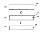
上記工程5まで経た時点で、ガラス表面には表層が変質した、具体的にはガラスの中心に存在する中間層30(バルク)よりも低密度化された、低密度層10を有することとなる[図1(a)〜図1(b)]。低密度層とは、ガラスの最表面からNaやKが抜け(リーチングし)、代わりにHが入り込む(置換する)ことによって形成される。
以下、工程4及び工程5について詳述する。In the production method of the present invention, subsequently, the following steps are performed after the contact treatment between glass and an inorganic salt.
Step 4: Glass cleaning step 5: Acid treatment of glass after
Hereinafter,
(工程4−ガラスの洗浄−)
工程4では工水、イオン交換水等を用いてガラスの洗浄を行う。中でもイオン交換水が好ましい。洗浄の条件は用いる洗浄液によっても異なるが、イオン交換水を用いる場合には0〜100℃で洗浄することが付着した塩を完全に除去させる点から好ましい。(Step 4-Washing of glass-)
In
(工程5−酸処理−)
工程5では、工程4で洗浄したガラスに対して、さらに酸処理を行う。
ガラスの酸処理とは、酸性の溶液中に、ガラスを浸漬させることによって行い、これによりガラス表面のNa及び/又はKをHに置換することができる。
溶液は酸性であれば特に制限されずpH7未満であればよく、用いられる酸が弱酸であっても強酸であってもよい。具体的には塩酸、硝酸、硫酸、リン酸、酢酸、シュウ酸、炭酸及びクエン酸等の酸が好ましい。これらの酸は単独で用いても、複数を組み合わせて用いてもよい。(Step 5-acid treatment-)
In
The acid treatment of glass is performed by immersing the glass in an acidic solution, whereby Na and / or K on the glass surface can be replaced with H.
The solution is not particularly limited as long as it is acidic, and may have a pH of less than 7, and the acid used may be a weak acid or a strong acid. Specifically, acids such as hydrochloric acid, nitric acid, sulfuric acid, phosphoric acid, acetic acid, oxalic acid, carbonic acid and citric acid are preferable. These acids may be used alone or in combination of two or more.
酸処理を行う温度は、用いる酸の種類や濃度、時間によっても異なるが、100℃以下で行うことが好ましい。
酸処理を行う時間は、用いる酸の種類や濃度、温度によっても異なるものの、10秒〜5時間が生産性の点から好ましく、1分〜2時間がより好ましい。
酸処理を行う溶液の濃度は、用いる酸の種類や時間、温度によって異なるものの、容器腐食の懸念が少ない濃度が好ましく、具体的には0.05重量%〜20重量%が好ましい。The temperature for the acid treatment varies depending on the type and concentration of the acid used and the time, but it is preferably 100 ° C. or lower.
The time for performing the acid treatment varies depending on the type and concentration of the acid used and the temperature, but is preferably 10 seconds to 5 hours from the viewpoint of productivity, and more preferably 1 minute to 2 hours.
The concentration of the solution to be acid-treated varies depending on the type of acid used, time and temperature, but is preferably such that there is little concern about container corrosion, and specifically 0.05% by weight to 20% by weight is preferable.
低密度層は、後述するアルカリ処理により除去されるため、低密度層が厚いほどガラス表面が除去されやすい。したがって低密度層の厚みはガラス表面除去量の観点から5nm以上が好ましく、20nm以上がより好ましい。低密度層の厚みは接触処理工程における融剤濃度、温度、時間等により制御することができる。 Since the low-density layer is removed by the alkali treatment described later, the thicker the low-density layer, the more easily the glass surface is removed. Therefore, the thickness of the low-density layer is preferably 5 nm or more, and more preferably 20 nm or more, from the viewpoint of the amount of glass surface removed. The thickness of the low density layer can be controlled by the flux concentration, temperature, time, etc. in the contact treatment step.
低密度層の密度はガラス表面除去性の観点から、ガラス中心部の深い領域(バルク)の密度に比べて低いことが好ましい。 The density of the low-density layer is preferably lower than the density of the deep region (bulk) at the center of the glass from the viewpoint of glass surface removability.
低密度層の厚みはX線反射率法(X−ray−Reflectometry:XRR)によって測定した周期(Δθ)から求めることができる。
低密度層の密度はXRRによって測定した臨界角(θc)により求めることができる。
なお、簡易的には走査型電子顕微鏡(SEM)でガラスの断面を観察することによって、低密度層の形成と層の厚みを確認することも可能である。The thickness of the low-density layer can be obtained from the period (Δθ) measured by the X-ray reflectance method (XRR).
The density of the low density layer can be determined by the critical angle (θc) measured by XRR.
It is also possible to confirm the formation of the low density layer and the layer thickness by simply observing the cross section of the glass with a scanning electron microscope (SEM).
本発明の製造方法では続いて、酸処理後に下記工程を行う。
工程6:アルカリ処理
上記工程6により、工程5までに形成された低密度層の一部又は全部を除去することができる[図1(b)〜図1(c)]。
以下、工程6について詳述する。In the production method of the present invention, subsequently, the following steps are performed after the acid treatment.
Step 6: Alkali treatment By the step 6, the low density layer formed up to the
Hereinafter, step 6 will be described in detail.
(工程6−アルカリ処理−)
工程6では、工程5で酸処理したガラスに対して、さらにアルカリ処理を行う。
アルカリ処理とは、塩基性の溶液中に、ガラスを浸漬させることによって行い、これにより低密度層の一部又は全部を除去することができる。
溶液は塩基性であれば特に制限されずpH7超過であればよく、弱塩基を用いても強塩基を用いてもよい。具体的には水酸化ナトリウム、水酸化カリウム、炭酸カリウム、炭酸ナトリウム等の塩基が好ましい。これらの塩基は単独で用いても、複数を組み合わせて用いてもよい。(Step 6-Alkali treatment-)
In step 6, the glass treated with acid in
The alkali treatment is carried out by immersing the glass in a basic solution, whereby a part or all of the low density layer can be removed.
The solution is not particularly limited as long as it is basic, as long as it has a pH of more than 7, and a weak base or a strong base may be used. Specifically, bases such as sodium hydroxide, potassium hydroxide, potassium carbonate and sodium carbonate are preferred. These bases may be used alone or in combination of two or more.
アルカリ処理を行う温度は、用いる塩基の種類や濃度、時間によっても異なるが、0〜100℃が好ましく、10〜80℃がより好ましく、20〜60℃が特に好ましい。かかる温度範囲であればガラスが腐食するおそれがなく好ましい。
アルカリ処理を行う時間は、用いる塩基の種類や濃度、温度によっても異なるものの、10秒間〜5時間が生産性の点から好ましく、1分間〜2時間がより好ましい。
アルカリ処理を行う溶液の濃度は、用いる塩基の種類や時間、温度によって異なるものの、ガラス表面除去性の観点から0.1重量%〜20重量%が好ましい。The temperature for performing the alkali treatment varies depending on the type and concentration of the base used and the time, but is preferably 0 to 100 ° C, more preferably 10 to 80 ° C, and particularly preferably 20 to 60 ° C. Within this temperature range, there is no risk of glass being corroded, which is preferable.
The time for performing the alkali treatment varies depending on the type and concentration of the base used and the temperature, but is preferably 10 seconds to 5 hours from the viewpoint of productivity, and more preferably 1 minute to 2 hours.
The concentration of the solution subjected to the alkali treatment varies depending on the type of the base used, time and temperature, but is preferably 0.1% by weight to 20% by weight from the viewpoint of glass surface removability.
上記アルカリ処理により、Hが侵入した低密度層の一部又は全部が除去され、サミット密度(Sds)が特定の範囲にある表層が露出する。これにより面強度が向上したガラスを得ることができる。さらに、低密度層が除去されることでガラスのボトム面に存在していた傷も同時に除去されるので、この点も強度向上に寄与すると考えられる。 By the alkali treatment, part or all of the low density layer in which H has penetrated is removed, and the surface layer having a summit density (Sds) within a specific range is exposed. This makes it possible to obtain glass with improved surface strength. Furthermore, by removing the low-density layer, the scratches existing on the bottom surface of the glass are also removed at the same time, which is also considered to contribute to the improvement of strength.
上記酸処理工程5およびアルカリ処理工程6の間や、アルカリ処理工程6の終了後に、工程4と同様の洗浄工程を有することが好ましい。
It is preferable to have a washing step similar to step 4 between the
本発明の製造方法によれば取り扱う薬液の安全性が高いため特別な設備を必要としない。したがって、面強度が格段に向上したフロートガラスを安全かつ効率的に得ることができる。 According to the manufacturing method of the present invention, since the chemical solution to be handled is highly safe, no special equipment is required. Therefore, it is possible to safely and efficiently obtain the float glass having a significantly improved surface strength.
なお、除去される低密度層の量は、アルカリ処理の条件による。図1(c)には、低密度層10が全て除去された態様を示すが、低密度層10の一部が除去され一部が残存していてもよい。強度向上の観点からは、低密度層の全部が取り除かれずとも効果を得ることができるが、ガラスの透過率を安定的に確保する観点から低密度層の全部を取り除くことが好ましい。
The amount of the low density layer to be removed depends on the conditions of alkali treatment. FIG. 1C shows a mode in which the
(化学強化)
本発明に係るフロートガラスは、化学強化処理に適用可能である。本発明の製造方法によってフロートガラスを得た後に、通常の化学強化処理を行い、化学強化ガラスを製造することができる。(Chemical strengthening)
The float glass according to the present invention can be applied to chemical strengthening treatment. After the float glass is obtained by the production method of the present invention, ordinary chemical strengthening treatment can be performed to produce the chemically strengthened glass.
以下に実施例を挙げ、本発明を具体的に説明するが、本発明はこれらに限定されない。 Hereinafter, the present invention will be described specifically with reference to Examples, but the present invention is not limited thereto.
<評価方法>
本実施例における各種評価は以下に示す分析方法により行った。<Evaluation method>
Various evaluations in this example were performed by the following analysis methods.
(ガラスの評価:サミット密度(Sds))
前述の〔AFM測定条件および画像解析ソフトの解析手順〕にて記載した方法に従い、サミット密度(Sds)を求めた。(Evaluation of glass: Summit density (Sds))
The summit density (Sds) was obtained according to the method described in the above [AFM measurement conditions and analysis procedure of image analysis software].
(ガラスの評価:除去量)
ガラスの除去量厚みは、薬液処理前後の重量を分析用電子天秤(HR−202i;AND製)により測定し、次の式を用いて厚み換算することにより求めた。
(片面あたりの除去量厚み)=((処理前重量)−(処理後重量))/(ガラス比重)/処理面積/2(Glass evaluation: amount removed)
The thickness of the amount of glass removed was determined by measuring the weight before and after the chemical treatment with an analytical electronic balance (HR-202i; manufactured by AND) and converting the thickness using the following formula.
(Thickness of removed amount per one side) = ((weight before treatment)-(weight after treatment)) / (glass specific gravity) / treatment area / 2
(ガラスの評価:面強度)
前述の〔ボールオンリング試験〕にて記載した方法に従い、ガラス面強度を測定した。(Evaluation of glass: surface strength)
The glass surface strength was measured according to the method described in the above [ball-on-ring test].
(ガラスの評価:水素濃度)
前述の〔水素濃度プロファイル測定方法〕にて記載した方法に従い、水素濃度プロファイルを測定し、関係式(I)を導出した。(Evaluation of glass: hydrogen concentration)
The hydrogen concentration profile was measured according to the method described in [Method for measuring hydrogen concentration profile] above, and the relational expression (I) was derived.
下記各試験例のうち、例1−1、1−2、2−1、2−2、3−1及び3−2は実施例であり、例1−3、2−3及び3−3は比較例である。 Of the following test examples, Examples 1-1, 1-2, 2-1, 2-2, 3-1 and 3-2 are examples, and Examples 1-3, 2-3 and 3-3 are examples. This is a comparative example.
<例1−1>
(無機塩とガラスとの接触工程)
SUS製のカップに硝酸ナトリウム938g、硝酸カリウム429g、炭酸ナトリウム33gを加え、マントルヒーターで430℃まで加熱して、K/Na質量比率0.62の溶融塩を調製した。フロート法により形成された50mm×50mm×0.56mmのガラスAを用意し、350℃に予熱した後、430℃の溶融塩に1時間浸漬し、室温付近まで冷却することにより接触処理を行った。得られたガラスは水洗いし、次の工程に供した。
ガラスA組成(モル%表示):SiO2 64.4%、Al2O3 8.0%、Na2O 12.5%、K2O 4.0%、MgO 10.5%、CaO 0.1%、SrO 0.1%、BaO 0.1%、ZrO2 0.5%
ガラスA比重(g/cm3):2.48<Example 1-1>
(Process of contacting inorganic salt with glass)
Sodium nitrate (938 g), potassium nitrate (429 g) and sodium carbonate (33 g) were added to a SUS cup and heated to 430 ° C. with a mantle heater to prepare a molten salt having a K / Na mass ratio of 0.62. A glass A having a size of 50 mm × 50 mm × 0.56 mm formed by the float method was prepared, preheated to 350 ° C., immersed in a molten salt at 430 ° C. for 1 hour, and cooled to near room temperature for contact treatment. .. The obtained glass was washed with water and subjected to the next step.
Glass A composition (in mol% display): SiO 2 64.4%, Al 2 O 3 8.0%, Na 2 O 12.5%, K 2 O 4.0%, MgO 10.5%,
Glass A specific gravity (g / cm 3 ): 2.48
(酸処理工程)
6.0重量%の硝酸(HNO3;関東化学社製)をビーカーに用意し、ウォーターバスを用いて40℃に温度調整を行った。前記接触処理工程で得られたガラスを、調整した塩酸中に120秒間浸漬させ、酸処理を行い、その後純水で数回洗浄した後、エアブローにより乾燥した。こうして得られたガラスを次の工程に供した。(Acid treatment process)
6.0 wt% nitric acid (HNO 3 ; manufactured by Kanto Chemical Co., Inc.) was prepared in a beaker, and the temperature was adjusted to 40 ° C. using a water bath. The glass obtained in the contact treatment step was immersed in the adjusted hydrochloric acid for 120 seconds, acid-treated, washed with pure water several times, and then dried by air blow. The glass thus obtained was subjected to the next step.
(アルカリ処理工程)
4.0重量%の水酸化ナトリウム水溶液をビーカーに用意し、ウォーターバスを用いて40℃に温度調整を行った。酸処理工程で得られたガラスを、調整した水酸化ナトリウム水溶液中に120秒間浸漬させ、アルカリ処理を行い、その後純水で数回洗浄した後、エアブローにより乾燥した。
以上より、例1−1のフロートガラスを得た。(Alkaline treatment process)
A 4.0 wt% sodium hydroxide aqueous solution was prepared in a beaker, and the temperature was adjusted to 40 ° C. using a water bath. The glass obtained in the acid treatment step was dipped in the adjusted sodium hydroxide aqueous solution for 120 seconds, subjected to alkali treatment, then washed with pure water several times, and then dried by air blow.
From the above, the float glass of Example 1-1 was obtained.
<例1−2>
無機塩との接触処理において、450℃の溶融塩に2時間浸漬した点以外は例1−1と同様に、例1−2のフロートガラスを得た。<Example 1-2>
A float glass of Example 1-2 was obtained in the same manner as in Example 1-1, except that the molten glass at 450 ° C. was immersed in the molten salt for 2 hours in the contact treatment with the inorganic salt.
<例1−3>
無機塩との接触処理、酸処理、および、アルカリ処理を実施していない点以外は例1−1同様に、例1−3のフロートガラスを得た。<Example 1-3>
A float glass of Example 1-3 was obtained in the same manner as in Example 1-1, except that the contact treatment with an inorganic salt, the acid treatment, and the alkali treatment were not carried out.
<例2−1>
SUS製のカップに硝酸ナトリウム1365g、炭酸ナトリウム35gを加え、マントルヒーターで430℃まで加熱して、K/Na質量比率0.0の溶融塩を調製した。フロート法により形成された50mm×50mm×0.56mmのガラスBを用意し、350℃に予熱した後、430℃の溶融塩に1時間浸漬し、室温付近まで冷却することにより接触処理を行った。得られたガラスは水洗いし、次の工程に供した。
ガラスB組成(モル%表示):SiO2 68%、Al2O3 10%、Na2O 14%、MgO 8%
ガラスB比重(g/cm3):2.41
酸処理とアルカリ処理は例1−1と同様に行い、例2−1のフロートガラスを得た。<Example 2-1>
To a SUS cup, 1365 g of sodium nitrate and 35 g of sodium carbonate were added, and heated to 430 ° C. with a mantle heater to prepare a molten salt having a K / Na mass ratio of 0.0. A glass B having a size of 50 mm × 50 mm × 0.56 mm formed by the float method was prepared, preheated to 350 ° C., immersed in a molten salt at 430 ° C. for 1 hour, and then cooled to around room temperature for contact treatment. .. The obtained glass was washed with water and subjected to the next step.
Glass B composition (expressed in mol%): SiO 2 68%, Al 2 O 3 10%, Na 2 O 14%, MgO 8%
Glass B specific gravity (g / cm 3 ): 2.41
The acid treatment and the alkali treatment were performed in the same manner as in Example 1-1 to obtain the float glass of Example 2-1.
<例2−2>
無機塩との接触処理において、450℃の溶融塩に2時間浸漬した点以外は例2−1と同様に、例2−2のフロートガラスを得た。<Example 2-2>
In the contact treatment with the inorganic salt, a float glass of Example 2-2 was obtained in the same manner as in Example 2-1, except that it was immersed in a molten salt at 450 ° C for 2 hours.
<例2−3>
無機塩との接触処理、酸処理、および、アルカリ処理を実施していない点以外は例2−1と同様に、例2−3のフロートガラスを得た。<Example 2-3>
A float glass of Example 2-3 was obtained in the same manner as in Example 2-1, except that the contact treatment with an inorganic salt, the acid treatment, and the alkali treatment were not carried out.
<例3−1>
SUS製のカップに硝酸ナトリウム5280g、硝酸カリウム84g、炭酸ナトリウム136gを加え、マントルヒーターで430℃まで加熱して、K/Na質量比率0.02の溶融塩を調製した。フロート法により形成された50mm×50mm×0.7mmのガラスCを用意し、350℃に予熱した後、430℃の溶融塩に1時間浸漬し、室温付近まで冷却することにより接触処理を行った。得られたガラスは水洗いし、次の工程に供した。
ガラスC組成(モル%表示):SiO2 68.5%、Al2O3 5%、Na2O 14.6%、MgO 4.1%、CaO 7.3%、K2O 0.2%
ガラスC比重(g/cm3):2.5
酸処理とアルカリ処理は例1−1と同様に行い、例3−1のフロートガラスを得た。<Example 3-1>
5280 g of sodium nitrate, 84 g of potassium nitrate and 136 g of sodium carbonate were added to a SUS cup and heated to 430 ° C. with a mantle heater to prepare a molten salt with a K / Na mass ratio of 0.02. A glass C having a size of 50 mm × 50 mm × 0.7 mm formed by the float method was prepared, preheated to 350 ° C., immersed in a molten salt at 430 ° C. for 1 hour, and cooled to near room temperature for contact treatment. .. The obtained glass was washed with water and subjected to the next step.
Glass C composition (in mol%): SiO 2 68.5%, Al 2 O 3 5%, Na 2 O 14.6%, MgO 4.1%, CaO 7.3%, K 2 O 0.2%
Glass C specific gravity (g / cm 3 ): 2.5
The acid treatment and the alkali treatment were performed in the same manner as in Example 1-1 to obtain the float glass of Example 3-1.
<例3−2>
無機塩との接触処理において、450℃の溶融塩に2時間浸漬した点以外は例3−1と同様に、例3−2のフロートガラスを得た。<Example 3-2>
In the contact treatment with the inorganic salt, a float glass of Example 3-2 was obtained in the same manner as in Example 3-1, except that the molten glass at 450 ° C was immersed for 2 hours.
<例3−3>
無機塩との接触処理、酸処理、および、アルカリ処理を実施していない点以外は例3−1同様に、例3−3のフロートガラスを得た。<Example 3-3>
A float glass of Example 3-3 was obtained in the same manner as in Example 3-1, except that the contact treatment with an inorganic salt, the acid treatment, and the alkali treatment were not carried out.
上記により得られた各フロートガラスの評価結果を表1に示す。
なお、ガラスの面強度については、例1−1及び例1−2に関しては例1−3の面強度を1としたとき、例2−1及び例2−2に関しては例2−3の面強度を1としたとき、例3−1及び例3−2に関しては例3−3の面強度を1としたときの、それぞれ相対比で表す。
また、図5〜7に、各例で得られた各フロートガラスの表層の水素濃度プロファイルをプロットしたグラフを示す。Table 1 shows the evaluation results of each float glass obtained as described above.
Regarding the surface strength of glass, when the surface strength of Example 1-3 was set to 1 in Examples 1-1 and 1-2, the surface of Example 2-3 was set in Examples 2-1 and 2-2. When the strength is set to 1, each of Examples 3-1 and 3-2 is represented by a relative ratio when the surface strength of Example 3-3 is set to 1.
5 to 7 are graphs in which the hydrogen concentration profile of the surface layer of each float glass obtained in each example is plotted.

本発明を詳細に、また特定の実施態様を参照して説明したが、本発明の精神と範囲を逸脱することなく様々な変更や修正を加えることができることは当業者にとって明らかである。本出願は2015年1月20日出願の日本特許出願(特願2015−008850)に基づくものであり、その内容はここに参照として取り込まれる。 Although the present invention has been described in detail and with reference to particular embodiments, it will be apparent to those skilled in the art that various changes and modifications can be made without departing from the spirit and scope of the invention. This application is based on the Japanese patent application filed on January 20, 2015 (Japanese Patent Application No. 2015-008850), the contents of which are incorporated herein by reference.
10 低密度層
30 中間層10 Low-
Claims (9)
フロート成形時に溶融金属と接するボトム面の、下記条件で測定したサミット密度(Sds)が4700以下である、フロートガラス。
サミット密度(Sds)測定条件: 原子間力顕微鏡(AFM、Atomic Force Microscope)(XE−HDM;Park systems社製)、測定モード:ノンコンタクトモード、スキャンサイズ:1μm×0.5μm、ピクセル数:256×128、カラースケール:±0.5nm、スキャン速度:1Hz、カンチレバー:Non−Contact Cantilever(Item:PPP−NCHR 10M;Park systems社製)により形状像を取得した後、AFM装置に付属されている画像解析ソフト(XEI)により、形状像のX方向、Y方向それぞれで平坦化処理を実施し、平坦化処理された形状像を、画像解析ソフト(SPIP6.2.6;イメージメトロロジー社製)を用い、形状像のL−フィルタリング処理(ISO値2.0μm)を実施し、ラフネス解析によりサミット密度(Sds)を求める。 There are no polishing scratches on the surface,
Float glass having a summit density (Sds) of 4700 or less measured under the following conditions on the bottom surface in contact with molten metal during float forming.
Summit density (Sds) measurement conditions: atomic force microscope (AFM, Atomic Force Microscope) (XE-HDM; manufactured by Park Systems), measurement mode: non-contact mode, scan size: 1 μm × 0.5 μm, number of pixels: 256 × 128, color scale: ± 0.5 nm, scan speed: 1 Hz, cantilever: Non-Contact Cantilever (Item: PPP-NCHR 10M; manufactured by Park Systems), and then attached to the AFM device. Image analysis software (XEI) is used to perform flattening processing in the X and Y directions of the shape image, and the flattened shape image is analyzed using image analysis software (SPIP 6.2.6; Image Metrology Co., Ltd.). Is used to perform L-filtering processing (ISO value 2.0 μm) of the shape image, and the summit density (Sds) is obtained by roughness analysis.
Y=aX+b (I)
〔式(I)における各記号の意味は下記の通りである。
Y:水素濃度(H2O換算、mol/L)
X:ガラス最表面からの深さ(μm)
a:−2.700以上
b:0.700以下〕 The float according to claim 1, wherein a straight line linearly approximating the hydrogen concentration Y in the region of depth X from the outermost surface of the glass satisfies the following relational expression (I) at X = 0.10 to 0.25 (μm). Glass.
Y = aX + b (I)
[The meaning of each symbol in formula (I) is as follows.
Y: Hydrogen concentration (H 2 O conversion, mol / L)
X: Depth from the outermost surface of the glass (μm)
a: -2.700 or more b: 0.700 or less]
前記無機塩との接触の後にガラスを洗浄する工程、
前記洗浄の後にガラスを酸処理する工程、及び
前記酸処理の後にガラスをアルカリ処理する工程を含み、
前記無機塩は、K2CO3、Na2CO3、KHCO3、NaHCO3、K3PO4、Na3PO4、K2SO4、Na2SO4、KOH及びNaOHからなる群より選ばれる少なくとも一種の融剤とを含み、前記無機塩におけるK/Na質量比率をA、ガラス組成中のK/Na質量比率をBとしたときに、A≧0でありA−B=−0.30〜+1.00の範囲となる、
フロートガラスの製造方法。 Contacting by immersing the glass molded by the float process in a molten salt of an inorganic salt,
Cleaning the glass after contact with the inorganic salt,
Comprising a step of acid-treating the glass after the cleaning, and a step of alkali-treating the glass after the acid treatment,
The inorganic salts are selected from K 2 CO 3, Na 2 CO 3, KHCO 3, NaHCO 3, K 3 PO 4, Na 3 PO 4, K 2 SO 4, Na 2 SO 4, KOH and the group consisting of NaOH When the K / Na mass ratio in the inorganic salt is A and the K / Na mass ratio in the glass composition is B, A ≧ 0 and A−B = −0.30 containing at least one flux. ~ +1.00 range,
Float glass manufacturing method.
前記無機塩との接触の後にガラスを洗浄する工程、
前記洗浄の後にガラスを酸処理する工程、及び
前記酸処理の後にガラスをアルカリ処理する工程を含み、
前記無機塩は、Li2CO3、LiHCO3、Li3PO4、Li2SO4及びLiOHからなる群より選ばれる少なくとも一種の融剤とを含み、前記無機塩におけるNa/Li質量比率をC、ガラス組成中のNa/Li質量比率をDとしたときに、C≧0でありC−D=−0.30〜+1.00の範囲となる、
フロートガラスの製造方法。 Contacting by immersing the glass molded by the float process in a molten salt of an inorganic salt,
Cleaning the glass after contact with the inorganic salt,
Comprising a step of acid-treating the glass after the cleaning, and a step of alkali-treating the glass after the acid treatment,
The inorganic salt contains at least one flux selected from the group consisting of Li 2 CO 3 , LiHCO 3 , Li 3 PO 4 , Li 2 SO 4 and LiOH, and the Na / Li mass ratio in the inorganic salt is C. When the Na / Li mass ratio in the glass composition is D, C ≧ 0 and C−D = −0.30 to +1.00.
Float glass manufacturing method.
Applications Claiming Priority (3)
| Application Number | Priority Date | Filing Date | Title |
|---|---|---|---|
| JP2015008850 | 2015-01-20 | ||
| JP2015008850 | 2015-01-20 | ||
| PCT/JP2016/051177 WO2016117478A1 (en) | 2015-01-20 | 2016-01-15 | Float glass |
Publications (2)
| Publication Number | Publication Date |
|---|---|
| JPWO2016117478A1 JPWO2016117478A1 (en) | 2017-10-26 |
| JP6696437B2 true JP6696437B2 (en) | 2020-05-20 |
Family
ID=56417024
Family Applications (1)
| Application Number | Title | Priority Date | Filing Date |
|---|---|---|---|
| JP2016570614A Active JP6696437B2 (en) | 2015-01-20 | 2016-01-15 | Float glass |
Country Status (3)
| Country | Link |
|---|---|
| JP (1) | JP6696437B2 (en) |
| CN (1) | CN107207311B (en) |
| WO (1) | WO2016117478A1 (en) |
Families Citing this family (4)
| Publication number | Priority date | Publication date | Assignee | Title |
|---|---|---|---|---|
| KR102436191B1 (en) * | 2016-09-30 | 2022-08-26 | 에이지씨 가부시키가이샤 | Method for manufacturing chemically tempered glass |
| CN114014539A (en) * | 2017-04-26 | 2022-02-08 | Agc株式会社 | chemically strengthened glass |
| WO2018235885A1 (en) * | 2017-06-23 | 2018-12-27 | Agc株式会社 | Chemical tempered glass |
| JP7024565B2 (en) * | 2018-04-04 | 2022-02-24 | Agc株式会社 | Manufacturing method of chemically strengthened glass |
Family Cites Families (6)
| Publication number | Priority date | Publication date | Assignee | Title |
|---|---|---|---|---|
| JP2000311336A (en) * | 1999-04-28 | 2000-11-07 | Nippon Sheet Glass Co Ltd | Manufacture of substrate for magnetic disk, substrate for magnetic disk resulted by this method and magnetic recording medium |
| JP2003141718A (en) * | 2001-10-31 | 2003-05-16 | Nippon Sheet Glass Co Ltd | Method of manufacturing glass substrate for information recording medium |
| TWI276614B (en) * | 2006-06-23 | 2007-03-21 | G Tech Optoelectronics Corp | Process for thinning glass substrate |
| JP2006324006A (en) * | 2006-08-28 | 2006-11-30 | Hoya Corp | Manufacturing method of glass substrate for information recording medium and glass substrate for information recording medium |
| JP5210584B2 (en) * | 2007-09-27 | 2013-06-12 | Hoya株式会社 | Manufacturing method of glass substrate for magnetic disk |
| WO2011145662A1 (en) * | 2010-05-20 | 2011-11-24 | 旭硝子株式会社 | Process for producing glass substrate for information recording medium and process for producing magnetic disk |
-
2016
- 2016-01-15 CN CN201680006565.8A patent/CN107207311B/en active Active
- 2016-01-15 WO PCT/JP2016/051177 patent/WO2016117478A1/en not_active Ceased
- 2016-01-15 JP JP2016570614A patent/JP6696437B2/en active Active
Also Published As
| Publication number | Publication date |
|---|---|
| CN107207311B (en) | 2020-07-31 |
| WO2016117478A1 (en) | 2016-07-28 |
| CN107207311A (en) | 2017-09-26 |
| JPWO2016117478A1 (en) | 2017-10-26 |
Similar Documents
| Publication | Publication Date | Title |
|---|---|---|
| JP5776859B2 (en) | Chemically tempered glass and method for producing the same | |
| JP7310966B2 (en) | chemically strengthened glass | |
| JP6809230B2 (en) | Chemically tempered glass and its manufacturing method | |
| JP6702470B2 (en) | Chemically tempered glass and method for manufacturing the same | |
| JP6696437B2 (en) | Float glass | |
| JP2017149628A (en) | Chemically strengthened glass and method for producing chemically strengthened glass |
Legal Events
| Date | Code | Title | Description |
|---|---|---|---|
| A621 | Written request for application examination |
Free format text: JAPANESE INTERMEDIATE CODE: A621 Effective date: 20180723 |
|
| A131 | Notification of reasons for refusal |
Free format text: JAPANESE INTERMEDIATE CODE: A131 Effective date: 20190820 |
|
| A601 | Written request for extension of time |
Free format text: JAPANESE INTERMEDIATE CODE: A601 Effective date: 20191018 |
|
| A521 | Request for written amendment filed |
Free format text: JAPANESE INTERMEDIATE CODE: A523 Effective date: 20191219 |
|
| TRDD | Decision of grant or rejection written | ||
| A01 | Written decision to grant a patent or to grant a registration (utility model) |
Free format text: JAPANESE INTERMEDIATE CODE: A01 Effective date: 20200324 |
|
| A61 | First payment of annual fees (during grant procedure) |
Free format text: JAPANESE INTERMEDIATE CODE: A61 Effective date: 20200406 |
|
| R150 | Certificate of patent or registration of utility model |
Ref document number: 6696437 Country of ref document: JP Free format text: JAPANESE INTERMEDIATE CODE: R150 |
|
| R250 | Receipt of annual fees |
Free format text: JAPANESE INTERMEDIATE CODE: R250 |
|
| R250 | Receipt of annual fees |
Free format text: JAPANESE INTERMEDIATE CODE: R250 |
|
| R250 | Receipt of annual fees |
Free format text: JAPANESE INTERMEDIATE CODE: R250 |