JP6694117B2 - Motorcycle - Google Patents
Motorcycle Download PDFInfo
- Publication number
- JP6694117B2 JP6694117B2 JP2019543723A JP2019543723A JP6694117B2 JP 6694117 B2 JP6694117 B2 JP 6694117B2 JP 2019543723 A JP2019543723 A JP 2019543723A JP 2019543723 A JP2019543723 A JP 2019543723A JP 6694117 B2 JP6694117 B2 JP 6694117B2
- Authority
- JP
- Japan
- Prior art keywords
- tread surface
- vehicle
- round tread
- tire
- rear tire
- Prior art date
- Legal status (The legal status is an assumption and is not a legal conclusion. Google has not performed a legal analysis and makes no representation as to the accuracy of the status listed.)
- Active
Links
Images


Classifications
-
- B—PERFORMING OPERATIONS; TRANSPORTING
- B62—LAND VEHICLES FOR TRAVELLING OTHERWISE THAN ON RAILS
- B62J—CYCLE SADDLES OR SEATS; AUXILIARY DEVICES OR ACCESSORIES SPECIALLY ADAPTED TO CYCLES AND NOT OTHERWISE PROVIDED FOR, e.g. ARTICLE CARRIERS OR CYCLE PROTECTORS
- B62J35/00—Fuel tanks specially adapted for motorcycles or engine-assisted cycles; Arrangements thereof
-
- B—PERFORMING OPERATIONS; TRANSPORTING
- B62—LAND VEHICLES FOR TRAVELLING OTHERWISE THAN ON RAILS
- B62K—CYCLES; CYCLE FRAMES; CYCLE STEERING DEVICES; RIDER-OPERATED TERMINAL CONTROLS SPECIALLY ADAPTED FOR CYCLES; CYCLE AXLE SUSPENSIONS; CYCLE SIDE-CARS, FORECARS, OR THE LIKE
- B62K11/00—Motorcycles, engine-assisted cycles or motor scooters with one or two wheels
- B62K11/02—Frames
-
- B—PERFORMING OPERATIONS; TRANSPORTING
- B62—LAND VEHICLES FOR TRAVELLING OTHERWISE THAN ON RAILS
- B62K—CYCLES; CYCLE FRAMES; CYCLE STEERING DEVICES; RIDER-OPERATED TERMINAL CONTROLS SPECIALLY ADAPTED FOR CYCLES; CYCLE AXLE SUSPENSIONS; CYCLE SIDE-CARS, FORECARS, OR THE LIKE
- B62K19/00—Cycle frames
- B62K19/30—Frame parts shaped to receive other cycle parts or accessories
- B62K19/38—Frame parts shaped to receive other cycle parts or accessories for attaching brake members
-
- B—PERFORMING OPERATIONS; TRANSPORTING
- B62—LAND VEHICLES FOR TRAVELLING OTHERWISE THAN ON RAILS
- B62K—CYCLES; CYCLE FRAMES; CYCLE STEERING DEVICES; RIDER-OPERATED TERMINAL CONTROLS SPECIALLY ADAPTED FOR CYCLES; CYCLE AXLE SUSPENSIONS; CYCLE SIDE-CARS, FORECARS, OR THE LIKE
- B62K25/00—Axle suspensions
- B62K25/04—Axle suspensions for mounting axles resiliently on cycle frame or fork
- B62K25/12—Axle suspensions for mounting axles resiliently on cycle frame or fork with rocking arm pivoted on each fork leg
- B62K25/14—Axle suspensions for mounting axles resiliently on cycle frame or fork with rocking arm pivoted on each fork leg with single arm on each fork leg
- B62K25/20—Axle suspensions for mounting axles resiliently on cycle frame or fork with rocking arm pivoted on each fork leg with single arm on each fork leg for rear wheel
Landscapes
- Engineering & Computer Science (AREA)
- Mechanical Engineering (AREA)
- Automatic Cycles, And Cycles In General (AREA)
- Axle Suspensions And Sidecars For Cycles (AREA)
- Motorcycle And Bicycle Frame (AREA)
- Lighting Device Outwards From Vehicle And Optical Signal (AREA)
- Tires In General (AREA)
Description
本発明は、後輪を支持するリヤフレームが中間フレームに対して揺動する構成の自動二輪車に関する。 The present invention relates to a motorcycle having a structure in which a rear frame supporting a rear wheel swings with respect to an intermediate frame.
例えば特許文献1に記載の自動二輪車は、前輪を回転可能に支持するフロントフレームと、後輪を回転可能に支持するリヤフレームが、それぞれ、中間フレームに揺動可能に支持された構成を有する。中間フレームに対する後輪の揺動によって、後輪が操舵される。特許文献1の自動二輪車は、リヤフレームを中間フレームに対して相対的に揺動させるアクチュエータを備えている。さらに、特許文献1の自動二輪車は、このアクチュエータを制御する制御装置を備えている。
For example, the motorcycle described in
特許文献1の自動二輪車は、乗員が着座するためのシートを有する。自動二輪車は、荷物を載置するための荷台を有する場合がある。乗員の重量の違い、乗員人数の違い、荷物の違いなどによって、自動二輪車の乗載荷重は異なる。特許文献1のように後輪を支持するリヤフレームが中間フレームに対して揺動する構成の自動二輪車は、乗載荷重の変化に対する後輪の揺動制御の制御性を高めることが求められている。
The motorcycle of
本発明は、乗員および荷物の少なくとも一方を乗載可能で、後輪を支持するリヤフレームが中間フレームに対して揺動する構成の自動二輪車において、乗載重量の変化に対する後輪の揺動制御の制御性を向上させることを目的とする。 The present invention relates to a motorcycle in which at least one of an occupant and luggage can be loaded, and a rear frame supporting a rear wheel oscillates with respect to an intermediate frame. The purpose is to improve the controllability of.
本願発明者らは、特許文献1の自動二輪車の乗載荷重を変えて、後輪の揺動制御を行った。その結果、乗載荷重が変わると、求める車両の挙動が得られるように後輪の揺動制御を行うことが難しいことがわかった。具体的には、例えば、乗載荷重が変わると、後輪を同じ角度だけ揺動させるのに必要なトルクの大きさが変わる場合がある。本願発明者らは、後輪の揺動中心軸線の位置を検討する中で、後輪の揺動中心軸線の位置と、後輪の揺動制御の制御性との関係について検討してみた。試行錯誤する中で、乗員等を含めた車両の重心の位置が後輪の揺動中心軸線から遠いほど、後輪の揺動制御の制御性が低くなることに気付いた。さらなる検討の結果、後輪の揺動中心軸線の位置と、乗員等を含めた車両の重心の位置と、乗員等が乗載されるシートまたは荷台の位置との関係を工夫することで、乗載重量の変化に対する後輪の揺動制御の制御性を向上できることに気付いた。具体的には、本願発明者らは、車両単体の重心と乗員等が乗載されるシート等との間に、後輪の揺動中心軸線を配置した。そうすることで、乗載荷重がゼロから増加するにつれて、乗員等を含めた車両の重心が後輪の揺動中心軸線に近づく。その結果、乗載重量の変化に対する後輪の揺動制御の制御性を高めることができる。
The inventors of the present application performed swing control of the rear wheels by changing the riding load of the motorcycle of
(1)本発明の自動二輪車は、中間フレームと、車両が直進可能に直立した状態で車両前方向または車両後方向に見て円弧状であるトレッド面を有するラウンドトレッド面フロントタイヤと、前記ラウンドトレッド面フロントタイヤから車両後方向に離れており、車両が直進可能に直立した状態で車両前方向または車両後方向に見て円弧状であるトレッド面を有するラウンドトレッド面リヤタイヤと、(a−1)前記ラウンドトレッド面フロントタイヤをその中心を通るフロント車軸線回りに回転可能に支持すると共に、(a−2)車両後方向に向かうほど車両上方向に向かう傾きを持つラウンドトレッド面フロントタイヤ揺動軸線回りに前記ラウンドトレッド面フロントタイヤが前記中間フレームに対して揺動可能となるように、前記ラウンドトレッド面フロントタイヤ揺動軸線回りに揺動可能に前記中間フレームに支持されるフロントフレームと、(b−1)前記ラウンドトレッド面リヤタイヤをその中心を通るリヤ車軸線回りに回転可能に支持すると共に、(b−2)車両後方向に向かうほど車両下方向に向かう傾きを持つラウンドトレッド面リヤタイヤ揺動軸線回りに前記ラウンドトレッド面リヤタイヤが前記中間フレームに対して揺動可能となるように、前記ラウンドトレッド面リヤタイヤ揺動軸線回りに揺動可能に前記中間フレームに支持されるリヤフレームと、前記中間フレームまたは前記リヤフレームに支持されており、直進可能に直立した状態の車両を車両左方向または車両右方向に見て少なくとも一部が前記ラウンドトレッド面リヤタイヤ揺動軸線から車両上方向に離れており、乗員が着座するためのシートまたは荷物を載置するための荷台と、前記リヤフレームを前記ラウンドトレッド面リヤタイヤ揺動軸線回りに前記中間フレームに対して揺動させることで、前記ラウンドトレッド面リヤタイヤを前記ラウンドトレッド面リヤタイヤ揺動軸線回りに前記中間フレームに対して揺動させるラウンドトレッド面リヤタイヤ揺動アクチュエータと、前記ラウンドトレッド面リヤタイヤ揺動アクチュエータを制御するラウンドトレッド面リヤタイヤ揺動制御装置と、前記ラウンドトレッド面フロントタイヤまたは前記ラウンドトレッド面リヤタイヤに駆動力を付与する駆動源と、を備える。直進可能に直立した状態の車両を車両左方向または車両右方向に見て、前記ラウンドトレッド面リヤタイヤ揺動軸線が、外部から荷重がかかっていない状態の車両の重心と前記シートまたは前記荷台との間を通るように、かつ、前記シートまたは前記荷台にかかる荷重がゼロから増大するにつれて、前記シートまたは前記荷台に乗載された前記乗員または前記荷物を含む車両の重心が前記ラウンドトレッド面リヤタイヤ揺動軸線に近づくように、前記中間フレーム、前記フロントフレーム、前記リヤフレーム、前記ラウンドトレッド面フロントタイヤ、前記ラウンドトレッド面リヤタイヤ、前記ラウンドトレッド面リヤタイヤ揺動アクチュエータ、および前記ラウンドトレッド面リヤタイヤ揺動制御装置が形成または配置されている。 (1) A motorcycle according to the present invention includes an intermediate frame, a round tread surface front tire having a tread surface that is arcuate when viewed in a vehicle front direction or a vehicle rear direction in a state where the vehicle stands upright so that the vehicle can go straight, and the round. A round tread surface rear tire having a tread surface which is separated from the tread surface front tire in the vehicle rear direction and is arcuate when viewed in the vehicle front direction or the vehicle rear direction in a state where the vehicle stands upright so that the vehicle can go straight; ) While supporting the round tread surface front tire rotatably around the front axle passing through the center thereof, (a-2) round tread surface front tire swing having an inclination toward the vehicle upward as it goes toward the vehicle rearward direction. The louver is arranged so that the round tread surface front tire can swing about the axis with respect to the intermediate frame. A front frame which is supported by the intermediate frame so as to be capable of swinging about the swing axis of the tread surface front tire; and (b-1) which supports the round tread surface rear tire rotatably about a rear axle passing through the center thereof. And (b-2) the round tread surface rear tire having a tilt toward the vehicle lower side as it goes toward the vehicle rearward, so that the round tread surface rear tire can swing with respect to the intermediate frame. Round tread surface Rear tire A rear frame that is supported by the intermediate frame so as to be swingable around the swing axis, and a vehicle that is supported by the intermediate frame or the rear frame and is in an upright state so that the vehicle can go straight to the left or When viewed from the right side of the vehicle, at least a part of the round tread surface is on the vehicle from the rear tire swing axis. In a direction away from each other, by swinging the rear frame with respect to the intermediate frame around the round tread surface rear tire swing axis, and a loading platform for mounting a seat or luggage for an occupant to sit on. A round tread surface rear tire swing actuator that swings the round tread surface rear tire around the round tread surface rear tire swing axis with respect to the intermediate frame, and a round tread surface rear tire swing actuator that controls the round tread surface rear tire swing actuator. A dynamic control device and a drive source that applies a driving force to the round tread surface front tire or the round tread surface rear tire. Looking at the vehicle in an upright state so that it can go straight, in the vehicle left direction or the vehicle right direction, the round tread surface rear tire swing axis is the center of gravity of the vehicle in a state where no load is applied from the outside and the seat or the bed. The center of gravity of the vehicle including the occupant or the luggage mounted on the seat or the luggage carrier is increased by the load on the seat or the luggage carrier from zero as the load passes on the seat or the luggage carrier from zero. The intermediate frame, the front frame, the rear frame, the round tread surface front tire, the round tread surface rear tire, the round tread surface rear tire swing actuator, and the round tread surface rear tire swing control so as to approach the dynamic axis. A device is formed or arranged.
自動二輪車は、ラウンドトレッド面フロントタイヤと、ラウンドトレッド面リヤタイヤと、中間フレームと、フロントフレームと、リヤフレームと、ラウンドトレッド面リヤタイヤ揺動アクチュエータと、ラウンドトレッド面リヤタイヤ揺動制御装置と、駆動源とを備える。ラウンドトレッド面フロントタイヤは、車両1が直進可能に直立した状態で車両前方向または車両後方向に見て円弧状であるトレッド面を有する。それにより、ラウンドトレッド面フロントタイヤは、車両上下方向に対して車両左右方向に傾斜することができる。ラウンドトレッド面リヤタイヤは、ラウンドトレッド面フロントタイヤから車両後方向に離れている。ラウンドトレッド面リヤタイヤは、車両1が直進可能に直立した状態で車両前方向または車両後方向に見て円弧状であるトレッド面を有する。それにより、ラウンドトレッド面リヤタイヤは、車両上下方向に対して車両左右方向に傾斜することができる。フロントフレームは、ラウンドトレッド面フロントタイヤをフロント車軸線回りに回転可能に支持する。フロント車軸線は、ラウンドトレッド面フロントタイヤの中心を通る軸線である。フロントフレームは、ラウンドトレッド面フロントタイヤがラウンドトレッド面フロントタイヤ揺動軸線回りに中間フレームに対して揺動可能となるように、ラウンドトレッド面フロントタイヤ揺動軸線回りに揺動可能に中間フレームに支持される。ラウンドトレッド面フロントタイヤ揺動軸線は、車両後方向に向かうほど車両上方向に向かう傾きを持つ。リヤフレームは、ラウンドトレッド面リヤタイヤをリヤ車軸線回りに回転可能に支持する。リヤ車軸線は、ラウンドトレッド面フロントタイヤの中心を通る軸線である。リヤフレームは、ラウンドトレッド面リヤタイヤがラウンドトレッド面リヤタイヤ揺動軸線回りに中間フレームに対して揺動可能となるように、ラウンドトレッド面リヤタイヤ揺動軸線回りに揺動可能に中間フレームに支持される。ラウンドトレッド面リヤタイヤ揺動軸線は、車両後方向に向かうほど車両下方向に向かう傾きを持つ。ラウンドトレッド面リヤタイヤ揺動アクチュエータは、リヤフレームをラウンドトレッド面リヤタイヤ揺動軸線回りに中間フレームに対して揺動させることで、ラウンドトレッド面リヤタイヤをラウンドトレッド面リヤタイヤ揺動軸線回りに中間フレームに対して揺動させる。ラウンドトレッド面リヤタイヤ揺動制御装置は、ラウンドトレッド面リヤタイヤ揺動アクチュエータを制御する。駆動源は、ラウンドトレッド面フロントタイヤまたはラウンドトレッド面リヤタイヤに駆動力を付与する。また、自動二輪車は、乗員が着座するためのシートまたは荷物を載置するための荷台を有する。シートまたは荷台は、中間フレームまたはリヤフレームに支持される。直進可能に直立した状態の車両を車両左方向または車両右方向に見て、シートまたは荷台の少なくとも一部は、ラウンドトレッド面リヤタイヤ揺動軸線から車両上方向に離れている。中間フレーム、フロントフレーム、リヤフレーム、ラウンドトレッド面フロントタイヤ、ラウンドトレッド面リヤタイヤ、ラウンドトレッド面リヤタイヤ揺動アクチュエータ、およびラウンドトレッド面リヤタイヤ揺動制御装置は、以下の2つの条件を満たすように、形成または配置されている。1つ目の条件は、直進可能に直立した状態の車両を車両左方向または車両右方向に見て、ラウンドトレッド面リヤタイヤ揺動軸線が、外部から荷重がかかっていない状態の車両の重心とシートまたは荷台との間を通ることである。2つ目の条件は、シートまたは荷台にかかる荷重がゼロから増大するにつれて、シートまたは荷台に乗載された乗員または荷物を含む車両の重心がラウンドトレッド面リヤタイヤ揺動軸線に近づくことである。
A motorcycle includes a round tread surface front tire, a round tread surface rear tire, an intermediate frame, a front frame, a rear frame, a round tread surface rear tire swing actuator, a round tread surface rear tire swing control device, and a drive source. With. The round tread surface front tire has a tread surface that is arcuate when viewed in the vehicle front direction or the vehicle rear direction when the
この構成によると、自動二輪車のシートまたは荷台に乗員または荷物が乗載されたとき、乗員または荷物を含む車両の重心が、ラウンドトレッド面リヤタイヤ揺動軸線に近づくように移動する。乗載荷重の大きさによっては、乗員等を含む車両の重心が最終的にラウンドトレッド面リヤタイヤ揺動軸線を越えることがある。しかし、乗載荷重が極端に大きくなることはないので、たとえ乗員等を含む車両の重心が、ラウンドトレッド面リヤタイヤ揺動軸線を越えたとしても、最終的にラウンドトレッド面リヤタイヤ揺動軸線から極端に離れることはない。また、乗員等を含む車両の重心が最終的にラウンドトレッド面リヤタイヤ揺動軸線を越える場合であっても、ラウンドトレッド面リヤタイヤ揺動軸線が、荷重がかかっていない状態の車両の重心から車両上方向に離れている場合に比べると、乗員等を含む車両の重心はラウンドトレッド面リヤタイヤ揺動軸線に近くなる。このように、乗員または荷物を含む車両の重心がラウンドトレッド面リヤタイヤ揺動軸線に近いため、自動二輪車の乗載荷重の変化に対するラウンドトレッド面リヤタイヤの揺動制御の制御性を向上できる。 According to this configuration, when an occupant or luggage is placed on the seat or bed of the motorcycle, the center of gravity of the vehicle including the occupant or luggage moves so as to approach the round tread surface rear tire swing axis. The center of gravity of a vehicle including an occupant may eventually exceed the swing axis of the rear tire of the round tread surface depending on the magnitude of the load on the vehicle. However, since the loading load does not become extremely large, even if the center of gravity of the vehicle including the occupants and the like exceeds the round tread surface rear tire swing axis, it will be extremely extreme from the round tread surface rear tire swing axis. Never leave. Even when the center of gravity of the vehicle including the occupants and the like finally exceeds the round tread surface rear tire swing axis, the round tread surface rear tire swing axis moves above the vehicle from the center of gravity of the vehicle in the unloaded state. The center of gravity of the vehicle including the occupant and the like is closer to the swing axis of the rear tire of the round tread surface, as compared with the case of being separated in the direction. As described above, the center of gravity of the vehicle including the occupant or the luggage is close to the swing axis of the rear tire of the round tread surface, so that the controllability of the swing control of the rear tire of the round tread surface with respect to the change in the riding load of the motorcycle can be improved.
(2)本発明の1つ観点によると、本発明の自動二輪車は、以下の構成を有することが好ましい。
直進可能に直立した状態の車両を車両左方向または車両右方向に見て、前記ラウンドトレッド面リヤタイヤ揺動軸線と路面との交点が、前記ラウンドトレッド面リヤタイヤの前端を通り車両上下方向に平行な直線と、前記ラウンドトレッド面リヤタイヤの後端を通り車両上下方向に平行な直線との間にある。(2) According to one aspect of the invention, the motorcycle of the invention preferably has the following configuration.
Looking at the vehicle in an upright state so that it can go straight ahead, the intersection of the round tread surface rear tire swing axis and the road surface is parallel to the vehicle vertical direction passing through the front end of the round tread surface rear tire. It is between a straight line and a straight line passing through the rear end of the round tread surface rear tire and parallel to the vehicle vertical direction.
この構成によると、ラウンドトレッド面リヤタイヤ揺動軸線と路面との交点が、ラウンドトレッド面リヤタイヤの前端を通り車両上下方向に平行な直線から車両前方向に離れている場合に比べて、ラウンドトレッド面リヤタイヤを揺動させるために必要なモーメントが小さい。また、ラウンドトレッド面リヤタイヤ揺動軸線と路面との交点が、ラウンドトレッド面リヤタイヤの後端を通り車両上下方向に平行な直線から車両後方向に離れている場合に比べて、ラウンドトレッド面リヤタイヤを揺動させるために必要なモーメントが小さい。そのため、ラウンドトレッド面リヤタイヤの揺動制御の制御性を向上できる。よって、自動二輪車の乗載荷重の変化に対するラウンドトレッド面リヤタイヤの揺動制御の制御性をより向上できる。 According to this configuration, the intersection of the rocking axis of the rear tire of the round tread surface and the road surface is greater than that of the case where the intersection of the road axis of the rear tire and the road surface is separated from the straight line that passes through the front end of the rear tire of the round tread surface and is parallel to the vertical direction of the vehicle. The moment required to swing the rear tire is small. In addition, compared with the case where the intersection point of the swing axis of the rear tire of the round tread surface and the road surface is separated from the straight line passing through the rear end of the rear tire of the round tread surface and parallel to the vertical direction of the vehicle in the rear direction of the vehicle, The moment required for rocking is small. Therefore, the controllability of the swing control of the round tread surface rear tire can be improved. Therefore, the controllability of the rocking control of the rear tire of the round tread surface with respect to the change in the riding load of the motorcycle can be further improved.
(3)本発明の1つ観点によると、本発明の自動二輪車は、以下の構成を有することが好ましい。
前記駆動源が電気モータを含む。本発明の自動二輪車は、前記電気モータに供給される電力を蓄える蓄電装置を備える。直進可能に直立した状態の車両を車両左方向または車両右方向に見て、前記蓄電装置の少なくとも一部が、前記ラウンドトレッド面リヤタイヤ揺動軸線から車両下方向に離れている。(3) According to one aspect of the present invention, the motorcycle of the present invention preferably has the following configuration.
The drive source includes an electric motor. The motorcycle of the present invention includes a power storage device that stores electric power supplied to the electric motor. At least a part of the power storage device is away from the round tread surface rear tire swing axis in the vehicle downward direction when the vehicle in an upright state capable of going straight is viewed in the vehicle left direction or the vehicle right direction.
この構成によると、比較的大きい重量を有する蓄電装置の少なくとも一部が、ラウンドトレッド面リヤタイヤ揺動軸線から車両下方向に離れている。そのため、シート等に荷重がかかっていない状態の車両の重心とシート等との間にラウンドトレッド面リヤタイヤ揺動軸線が位置するレイアウトを、容易に実現できる。 According to this configuration, at least a part of the power storage device having a relatively large weight is separated from the round tread surface rear tire swing axis in the vehicle downward direction. Therefore, it is possible to easily realize a layout in which the round tread surface rear tire swing axis is located between the center of gravity of the vehicle and the seat or the like when no load is applied to the seat or the like.
(4)本発明の1つ観点によると、本発明の自動二輪車は、以下の構成を有することが好ましい。
本発明の自動二輪車は、前記フロントフレームを前記ラウンドトレッド面フロントタイヤ揺動軸線回りに前記中間フレームに対して揺動させることで、前記ラウンドトレッド面フロントタイヤを前記ラウンドトレッド面フロントタイヤ揺動軸線回りに前記中間フレームに対して揺動させるラウンドトレッド面フロントタイヤ揺動アクチュエータと、前記ラウンドトレッド面フロントタイヤ揺動アクチュエータを制御するラウンドトレッド面フロントタイヤ揺動制御装置と、を備える。(4) According to one aspect of the invention, the motorcycle of the invention preferably has the following configuration.
In the motorcycle of the present invention, by swinging the front frame around the round tread surface front tire swing axis with respect to the intermediate frame, the round tread surface front tire is rotated by the round tread surface front tire swing axis. A round tread surface front tire rocking actuator that rocks around the intermediate frame and a round tread surface front tire rocking control device that controls the round tread surface front tire rocking actuator are provided.
この構成によると、ラウンドトレッド面フロントタイヤのラウンドトレッド面フロントタイヤ揺動軸線回りの揺動が、ラウンドトレッド面フロントタイヤ揺動制御装置によって制御される。したがって、ラウンドトレッド面リヤタイヤの揺動と、ラウンドトレッド面フロントタイヤの揺動とを連動させて行うことができる。そのため、ラウンドトレッド面リヤタイヤの揺動制御の制御性を向上できる。よって、自動二輪車の乗載荷重の変化に対するラウンドトレッド面リヤタイヤの揺動制御の制御性をより向上できる。 According to this configuration, the swinging of the round tread surface front tire around the round tread surface front tire swing axis is controlled by the round tread surface front tire swing control device. Therefore, the swing of the rear tire of the round tread surface and the swing of the front tire of the round tread surface can be interlocked with each other. Therefore, the controllability of the swing control of the round tread surface rear tire can be improved. Therefore, the controllability of the rocking control of the rear tire of the round tread surface with respect to the change in the riding load of the motorcycle can be further improved.
(5)本発明の1つ観点によると、本発明の自動二輪車は、以下の構成を有することが好ましい。
直進可能に直立した状態の車両を車両左方向または車両右方向に見て、前記ラウンドトレッド面フロントタイヤ揺動アクチュエータの少なくとも一部が、前記ラウンドトレッド面リヤタイヤ揺動軸線から車両下方向に離れている。(5) According to one aspect of the invention, the motorcycle of the invention preferably has the following configuration.
Looking at the vehicle in an upright state so that it can go straight ahead, at least part of the round tread surface front tire swing actuator is separated from the round tread surface rear tire swing axis in the vehicle downward direction. There is.
この構成によると、比較的大きい重量を有するラウンドトレッド面フロントタイヤ揺動アクチュエータの少なくとも一部が、ラウンドトレッド面リヤタイヤ揺動軸線から車両下方向に離れている。そのため、シート等に荷重がかかっていない状態の車両の重心とシート等との間にラウンドトレッド面リヤタイヤ揺動軸線が位置するレイアウトを、容易に実現できる。 According to this configuration, at least a part of the round tread surface front tire swing actuator having a relatively large weight is separated from the round tread surface rear tire swing axis in the vehicle downward direction. Therefore, it is possible to easily realize a layout in which the round tread surface rear tire swing axis is located between the center of gravity of the vehicle and the seat or the like when no load is applied to the seat or the like.
(6)本発明の1つ観点によると、本発明の自動二輪車は、以下の構成を有することが好ましい。
前記リヤフレームは、前記ラウンドトレッド面リヤタイヤを前記リヤ車軸線回りに回転可能に支持すると共に、前記ラウンドトレッド面リヤタイヤが受ける車両上下方向の振動を吸収するリヤサスペンションユニットを含む。直進可能に直立した状態の車両を車両左方向または車両右方向に見て、前記リヤサスペンションユニットの一部が、前記ラウンドトレッド面リヤタイヤ揺動軸線から車両下方向に離れている。(6) According to one aspect of the invention, the motorcycle of the invention preferably has the following configuration.
The rear frame includes a rear suspension unit that supports the round tread surface rear tire rotatably around the rear axle and absorbs vibration in the vehicle vertical direction received by the round tread surface rear tire. When the vehicle in an upright state so as to be able to go straight is viewed in the vehicle left direction or the vehicle right direction, a part of the rear suspension unit is separated from the round tread surface rear tire swing axis in the vehicle downward direction.
この構成によると、比較的大きい重量を有するリヤサスペンションユニットの一部が、ラウンドトレッド面リヤタイヤ揺動軸線から車両下方向に離れている。そのため、シート等に荷重がかかっていない状態の車両の重心とシート等との間にラウンドトレッド面リヤタイヤ揺動軸線が位置するレイアウトを、容易に実現できる。 With this configuration, a part of the rear suspension unit having a relatively large weight is separated from the round tread surface rear tire swing axis in the vehicle downward direction. Therefore, it is possible to easily realize a layout in which the round tread surface rear tire swing axis is located between the center of gravity of the vehicle and the seat or the like when no load is applied to the seat or the like.
(7)本発明の1つ観点によると、本発明の自動二輪車は、以下の構成を有することが好ましい。
本発明の自動二輪車は、前記ラウンドトレッド面フロントタイヤまたは前記ラウンドトレッド面リヤタイヤに制動力を付与する液圧式ブレーキと、前記液圧式ブレーキの液圧を制御するハイドロリックユニットと、を備える。直進可能に直立した状態の車両を車両左方向または車両右方向に見て、前記ハイドロリックユニットの少なくとも一部が、前記ラウンドトレッド面リヤタイヤ揺動軸線から車両下方向に離れている。(7) According to one aspect of the invention, the motorcycle of the invention preferably has the following configuration.
The motorcycle of the present invention includes a hydraulic brake that applies a braking force to the round tread surface front tire or the round tread surface rear tire, and a hydraulic unit that controls the hydraulic pressure of the hydraulic brake. At least a part of the hydraulic unit is separated from the round tread rear tire swing axis in the vehicle downward direction when the vehicle in an upright state so as to be able to travel straight is viewed in the vehicle left direction or the vehicle right direction.
この構成によると、比較的大きい重量を有するハイドロリックユニットの少なくとも一部が、ラウンドトレッド面リヤタイヤ揺動軸線から車両下方向に離れている。そのため、シート等に荷重がかかっていない状態の車両の重心とシート等との間にラウンドトレッド面リヤタイヤ揺動軸線が位置するレイアウトを、容易に実現できる。 With this configuration, at least a part of the hydraulic unit having a relatively large weight is separated from the round tread surface rear tire swing axis in the vehicle downward direction. Therefore, it is possible to easily realize a layout in which the round tread surface rear tire swing axis is located between the center of gravity of the vehicle and the seat or the like when no load is applied to the seat or the like.
(8)本発明の1つ観点によると、本発明の自動二輪車は、以下の構成を有することが好ましい。
本発明の自動二輪車は、前記中間フレームに設置され、前記中間フレームの車両上下方向に対する車両左右方向への傾きに関連する物理量を検出する傾斜検出装置を備える。(8) According to one aspect of the present invention, the motorcycle of the present invention preferably has the following configuration.
The motorcycle of the present invention includes a tilt detection device that is installed in the intermediate frame and that detects a physical quantity related to a tilt of the intermediate frame in the vehicle left-right direction with respect to the vehicle vertical direction.
仮に、傾斜検出装置がリヤフレームに設置される場合、傾斜検出装置の検出結果から中間フレームの傾きを検出するには、リヤフレームの中間フレームに対する揺動角度等を考慮した補正を行う必要がある。傾斜検出装置が中間フレームに設置されていることにより、求める車両の挙動が得られるようにラウンドトレッド面リヤタイヤの揺動制御を行うことが容易になる。よって、自動二輪車の乗載荷重の変化に対するラウンドトレッド面リヤタイヤの揺動制御の制御性をより向上できる。 If the tilt detection device is installed on the rear frame, it is necessary to perform correction in consideration of the swing angle of the rear frame with respect to the intermediate frame in order to detect the tilt of the intermediate frame from the detection result of the tilt detection device. .. Since the inclination detection device is installed in the intermediate frame, it becomes easy to control the swing of the rear tire of the round tread surface so that the desired vehicle behavior can be obtained. Therefore, the controllability of the rocking control of the rear tire of the round tread surface with respect to the change in the riding load of the motorcycle can be further improved.
(9)本発明の1つ観点によると、本発明の自動二輪車は、以下の構成を有することが好ましい。
車両が直進可能に直立した状態において、前記ラウンドトレッド面リヤタイヤ揺動アクチュエータの少なくとも一部が、前記ラウンドトレッド面リヤタイヤおよび前記ラウンドトレッド面フロントタイヤの少なくとも一方の上端よりも車両下方向に位置する。(9) According to one aspect of the invention, the motorcycle of the invention preferably has the following configuration.
In a state in which the vehicle is upright so that the vehicle can go straight, at least a part of the round tread surface rear tire swing actuator is located below the upper end of at least one of the round tread surface rear tire and the round tread surface front tire.
この構成によると、比較的大きい重量を有するラウンドトレッド面リヤタイヤ揺動アクチュエータが、車両の比較的低い位置に配置される。そのため、シート等に荷重がかかっていない状態の車両の重心とシート等との間にラウンドトレッド面リヤタイヤ揺動軸線が位置するレイアウトを、容易に実現できる。 According to this structure, the round tread surface rear tire swing actuator having a relatively large weight is arranged at a relatively low position of the vehicle. Therefore, it is possible to easily realize a layout in which the round tread surface rear tire swing axis is located between the center of gravity of the vehicle and the seat or the like when no load is applied to the seat or the like.
(10)本発明の1つ観点によると、本発明の自動二輪車は、以下の構成を有することが好ましい。
直進可能に直立した状態の車両を車両左方向または車両右方向に見て、前記駆動源の少なくとも一部が、前記ラウンドトレッド面リヤタイヤ揺動軸線から車両下方向に離れている。(10) According to one aspect of the present invention, the motorcycle of the present invention preferably has the following configuration.
When the vehicle in an upright state so as to be able to go straight is viewed in the vehicle left direction or the vehicle right direction, at least a part of the drive source is away from the round tread surface rear tire swing axis in the vehicle downward direction.
この構成によると、比較的大きい重量を有する駆動源の少なくとも一部が、ラウンドトレッド面リヤタイヤ揺動軸線から車両下方向に離れている。そのため、シート等に荷重がかかっていない状態の車両の重心とシート等との間にラウンドトレッド面リヤタイヤ揺動軸線が位置するレイアウトを、容易に実現できる。 According to this structure, at least a part of the drive source having a relatively large weight is separated from the round tread surface rear tire swing axis in the vehicle downward direction. Therefore, it is possible to easily realize a layout in which the round tread surface rear tire swing axis is located between the center of gravity of the vehicle and the seat or the like when no load is applied to the seat or the like.
(11)本発明の1つ観点によると、本発明の自動二輪車は、以下の構成を有することが好ましい。
前記駆動源がエンジンユニットを含む。本発明の自動二輪車は、前記エンジンユニットに供給される燃料を貯留する燃料タンクを備える。直進可能に直立した状態の車両を車両下方向に見て、前記燃料タンクが、前記ラウンドトレッド面リヤタイヤ揺動軸線と重なる。(11) According to one aspect of the invention, the motorcycle of the invention preferably has the following configuration.
The drive source includes an engine unit. The motorcycle of the present invention includes a fuel tank that stores the fuel supplied to the engine unit. The fuel tank overlaps the round tread surface rear tire swing axis when the vehicle in an upright state so as to be able to go straight is seen in the vehicle downward direction.
この構成によると、直進可能に直立した状態の車両を車両下方向に見て、燃料タンクの一部は、ラウンドトレッド面リヤタイヤ揺動軸線と重なる。それにより、燃料タンク内の燃料の重量が変化しても、車両の重心の位置の変化が少ない。そのため、ラウンドトレッド面リヤタイヤの揺動制御の制御性の低下を抑えることができる。 According to this configuration, when the vehicle in an upright state so as to be able to travel straight is viewed in the vehicle downward direction, a part of the fuel tank overlaps the round tread surface rear tire swing axis. As a result, even if the weight of the fuel in the fuel tank changes, the position of the center of gravity of the vehicle does not change much. Therefore, it is possible to prevent the controllability of the rocking control of the round tread surface rear tire from decreasing.
(12)本発明の1つ観点によると、本発明の自動二輪車は、以下の構成を有することが好ましい。
前記中間フレームが、前記シートを支持するシートフレームを含む。(12) According to one aspect of the invention, the motorcycle of the invention preferably has the following configuration.
The intermediate frame includes a seat frame that supports the seat.
この構成によると、シートまたは荷台は中間フレームに支持されるため、リヤフレームは、シートに着座した乗員または荷台に載置された荷物の荷重を受けない。よって、リヤフレームがシートまたは荷台を支持する場合に比べて、ラウンドトレッド面リヤタイヤ揺動アクチュエータが揺動させる対象の重量が小さい。そのため、ラウンドトレッド面リヤタイヤの揺動制御の制御性を向上できる。よって、自動二輪車の乗載荷重の変化に対するラウンドトレッド面リヤタイヤの揺動制御の制御性をより向上できる。 According to this configuration, the seat or the luggage carrier is supported by the intermediate frame, so that the rear frame does not receive the load of the occupant seated on the seat or the load placed on the luggage carrier. Therefore, the weight of the object to be swung by the round tread surface rear tire swing actuator is smaller than when the rear frame supports the seat or the bed. Therefore, the controllability of the swing control of the round tread surface rear tire can be improved. Therefore, the controllability of the rocking control of the rear tire of the round tread surface with respect to the change in the riding load of the motorcycle can be further improved.
乗員または荷物によって、乗員または荷物の重量は異なる。リヤフレームがシートまたは荷台を支持する場合、乗員または荷物によって、ラウンドトレッド面リヤタイヤ揺動アクチュエータが揺動させる対象の重量が変化する。それにより、ラウンドトレッド面リヤタイヤの揺動制御が複雑になり難しくなる。特に低速走行時の制御が難しい。
一方、シートまたは荷台が中間フレームに支持される場合、乗員または荷物の重量が変化しても、ラウンドトレッド面リヤタイヤ揺動アクチュエータが揺動させる対象の重量は変化しない。そのため、ラウンドトレッド面リヤタイヤの揺動制御の制御性を向上できる。よって、自動二輪車の乗載荷重の変化に対するラウンドトレッド面リヤタイヤの揺動制御の制御性をより向上できる。The weight of the occupant or baggage varies depending on the occupant or baggage. When the rear frame supports the seat or the bed, the weight of the object to be swung by the round tread surface rear tire swing actuator changes depending on the occupant or luggage. As a result, the swing control of the round tread surface rear tire becomes complicated and difficult. Especially, control at low speed is difficult.
On the other hand, when the seat or the luggage carrier is supported by the intermediate frame, the weight of the object to be swung by the round tread surface rear tire swing actuator does not change even if the weight of the occupant or luggage changes. Therefore, the controllability of the swing control of the round tread surface rear tire can be improved. Therefore, the controllability of the swing control of the rear tire of the round tread surface with respect to the change in the riding load of the motorcycle can be further improved.
自動二輪車の走行中、乗員は重心を移動させる動作をする場合がある。特に、自動二輪車の旋回時に、乗員は重心を車両左方向または車両右方向に移動させる動作をする場合がある。リヤフレームがシートを支持する場合、乗員が重心を移動させる動作を行うと、ラウンドトレッド面リヤタイヤ揺動アクチュエータが揺動させる対象の重心が変化する。それにより、ラウンドトレッド面リヤタイヤの揺動制御が複雑になり難しくなる。特に低速走行時の制御が難しい。
一方、シートまたは荷台が中間フレームに支持される場合、乗員が重心を移動させる動作を行っても、ラウンドトレッド面リヤタイヤ揺動アクチュエータが揺動させる対象の重心は変化しない。そのため、ラウンドトレッド面リヤタイヤの揺動制御の制御性を向上できる。よって、自動二輪車の乗載荷重の変化に対するラウンドトレッド面リヤタイヤの揺動制御の制御性をより向上できる。While the motorcycle is traveling, the occupant may move the center of gravity. In particular, when the motorcycle turns, the occupant may move the center of gravity toward the left or right of the vehicle. When the rear frame supports the seat, when the occupant moves the center of gravity, the center of gravity of the object to be swung by the round tread surface rear tire swing actuator changes. As a result, the swing control of the round tread surface rear tire becomes complicated and difficult. Especially, control at low speed is difficult.
On the other hand, when the seat or the bed is supported by the intermediate frame, the center of gravity of the object to be swung by the round tread surface rear tire swing actuator does not change even if the occupant moves the center of gravity. Therefore, the controllability of the swing control of the round tread surface rear tire can be improved. Therefore, the controllability of the swing control of the rear tire of the round tread surface with respect to the change in the riding load of the motorcycle can be further improved.
(13)本発明の1つ観点によると、本発明の自動二輪車は、以下の構成を有することが好ましい。
前記リヤフレームが、前記シートを支持するシートフレームを含む。(13) According to one aspect of the invention, the motorcycle of the invention preferably has the following configuration.
The rear frame includes a seat frame that supports the seat.
(14)本発明の1つ観点によると、本発明の自動二輪車は、以下の構成を有することが好ましい。
本発明の自動二輪車が、前記中間フレームに接続され、車両上下方向に対して車両左右方向に傾いた状態で車両が自立するように路面に接地可能なサイドスタンドを備える。(14) According to one aspect of the invention, the motorcycle of the invention preferably has the following configuration.
The motorcycle of the present invention is provided with a side stand that is connected to the intermediate frame and is capable of grounding on a road surface so that the vehicle can stand on its own in a state of being inclined in the vehicle left-right direction with respect to the vehicle vertical direction.
(15)本発明の1つ観点によると、本発明の自動二輪車は、上記(14)の構成に加えて、以下の構成を有することが好ましい。
直進可能に直立した状態の車両を車両左方向または車両右方向に見て、前記ラウンドトレッド面リヤタイヤ揺動アクチュエータによって前記ラウンドトレッド面リヤタイヤ揺動軸線回りに前記中間フレームに対して揺動される対象全体の重心であるリヤ揺動重心が、前記ラウンドトレッド面リヤタイヤ揺動軸線から車両下方向に離れている。前記ラウンドトレッド面リヤタイヤ揺動制御装置は、前記サイドスタンドによって車両左方向に傾斜した状態で車両が自立している場合に、車両を起き上がらせるために、前記リヤ揺動重心が車両右方向に揺動してから車両左方向に揺動するように前記ラウンドトレッド面リヤタイヤ揺動アクチュエータを制御する。前記ラウンドトレッド面リヤタイヤ揺動制御装置は、前記サイドスタンドによって車両右方向に傾斜した状態で車両が自立している場合に、車両を起き上がらせるために、前記リヤ揺動重心が車両左方向に揺動してから車両右方向に揺動するように前記ラウンドトレッド面リヤタイヤ揺動アクチュエータを制御する。(15) According to one aspect of the present invention, the motorcycle of the present invention preferably has the following configuration in addition to the configuration of (14) above.
An object that is swung with respect to the intermediate frame around the round tread surface rear tire swing axis by the round tread surface rear tire swing actuator when the vehicle in an upright state capable of going straight is viewed in the vehicle left direction or the vehicle right direction. The center of gravity of the rear swing, which is the center of gravity of the whole body, is separated from the round tread surface rear tire swing axis in the vehicle downward direction. The round tread surface rear tire swing control device swings the rear swing center of gravity to the right of the vehicle to raise the vehicle when the vehicle is self-supporting with the side stand leaning to the left of the vehicle. Then, the round tread surface rear tire swing actuator is controlled so as to swing to the left of the vehicle. The round tread surface rear tire swing control device swings the rear swing center of gravity to the left of the vehicle in order to raise the vehicle when the vehicle is self-supporting with the side stand leaning to the right of the vehicle. Then, the round tread surface rear tire swing actuator is controlled so as to swing to the right of the vehicle.
ラウンドトレッド面リヤタイヤ揺動アクチュエータによってラウンドトレッド面リヤタイヤ揺動軸線回りに揺動される対象の重心をリヤ揺動重心とする。リヤ揺動重心は、ラウンドトレッド面リヤタイヤ揺動軸線から車両下方向に離れている。ラウンドトレッド面リヤタイヤ揺動制御装置は、サイドスタンドによって車両左方向に傾斜した状態で車両が自立している場合に、リヤ揺動重心が車両右方向に揺動してから車両左方向に揺動するようにラウンドトレッド面リヤタイヤ揺動アクチュエータを制御する。リヤフレームの車両左方向への揺動の反動により、車両は起き上がることができる。ラウンドトレッド面リヤタイヤ揺動制御装置は、サイドスタンドによって車両右方向に傾斜した状態で車両が自立している場合に、リヤ揺動重心が車両左方向に揺動してから車両右方向に揺動するようにラウンドトレッド面リヤタイヤ揺動アクチュエータを制御する。リヤフレームの車両右方向への揺動の反動により、車両は起き上がることができる。このように、人が車両を支えなくても車両を起き上がらせることができるため、自動二輪車の利便性を向上できる。サイドスタンドは中間フレームに接続されるため、リヤフレームの揺動をサイドスタンドが妨げない。 The center of gravity of the object that is swung around the round tread surface rear tire swing axis by the round tread surface rear tire swing actuator is the rear swing center of gravity. The rear swing center of gravity is separated from the round tread surface rear tire swing axis in the vehicle downward direction. The round tread surface rear tire swing control device swings the rear swing center of gravity to the vehicle rightward direction and then to the vehicle leftward direction when the vehicle is self-supporting with the side stand leaning to the vehicle leftward direction. In this way, the round tread surface rear tire swing actuator is controlled. The vehicle can get up due to the reaction of the swing of the rear frame to the left of the vehicle. The round tread surface rear tire swing control device swings the rear swing center of gravity to the left side of the vehicle and then swings to the right side of the vehicle when the vehicle is self-supporting with the side stand leaning to the right side of the vehicle. In this way, the round tread surface rear tire swing actuator is controlled. The vehicle can get up due to the reaction of the swing of the rear frame to the right of the vehicle. In this way, the vehicle can be raised without a person supporting the vehicle, so that the convenience of the motorcycle can be improved. Since the side stand is connected to the intermediate frame, the side stand does not prevent the rear frame from swinging.
(16)本発明の1つ観点によると、本発明の自動二輪車は、以下の構成を有することが好ましい。
前記フロントフレームは、前記ラウンドトレッド面フロントタイヤを前記フロント車軸線回りに回転可能に支持すると共に、前記ラウンドトレッド面フロントタイヤが受ける車両上下方向の振動を吸収するフロントサスペンションユニットを含む。直進可能に直立した状態の車両を車両左方向または車両右方向に見て、前記フロントサスペンションユニットの少なくとも一部が、前記ラウンドトレッド面リヤタイヤ揺動軸線から車両下方向に離れている。(16) According to one aspect of the invention, the motorcycle of the invention preferably has the following configuration.
The front frame includes a front suspension unit that supports the round tread surface front tire rotatably around the front axle and that absorbs vibration in the vehicle vertical direction received by the round tread surface front tire. At least a part of the front suspension unit is away from the round tread surface rear tire swing axis in the vehicle downward direction when the vehicle in an upright state capable of going straight is viewed in the vehicle left direction or the vehicle right direction.
この構成によると、比較的大きい重量を有するフロントサスペンションユニットの少なくとも一部が、ラウンドトレッド面リヤタイヤ揺動軸線から車両下方向に離れている。そのため、シート等に荷重がかかっていない状態の車両の重心とシート等との間にラウンドトレッド面リヤタイヤ揺動軸線が位置するレイアウトを、容易に実現できる。 With this configuration, at least a part of the front suspension unit having a relatively large weight is separated from the round tread surface rear tire swing axis in the vehicle downward direction. Therefore, it is possible to easily realize a layout in which the round tread surface rear tire swing axis is located between the center of gravity of the vehicle and the seat or the like when no load is applied to the seat or the like.
<用語の定義>
本発明において、「中間フレーム」、「フロントフレーム」および「リヤフレーム」は、車両において応力を主に受ける部材である。リヤフレームは、複数の部品を組み合わせたものであってもよく、一体成型されていてもよい。フロントフレームおよび中間フレームもリヤフレームと同様である。リヤフレームは、モノコック構造のフレームであってもよく、セミモノコック構造のフレームであってもよく、これら以外のフレーム構造ののフレームであってもよい。フロントフレームおよび中間フレームもリヤフレームと同様である。<Definition of terms>
In the present invention, the "intermediate frame", "front frame", and "rear frame" are members that are mainly subjected to stress in the vehicle. The rear frame may be a combination of a plurality of parts, or may be integrally molded. The front frame and the intermediate frame are similar to the rear frame. The rear frame may be a frame having a monocoque structure, a frame having a semi-monocoque structure, or a frame having a frame structure other than these. The front frame and the intermediate frame are similar to the rear frame.
本発明において、「トレッド面」とは、タイヤにおける路面と接する面である。 In the present invention, the “tread surface” is the surface of the tire that comes into contact with the road surface.
本発明において、「乗員」は、運転者であってもよいし、運転者でなくてもよい。運転者ではない乗員とは、自律運転される自動二輪車の乗員であってもよく、運転者と共に自動二輪車に乗車する乗員であってもよい。 In the present invention, the “occupant” may or may not be a driver. The occupant who is not the driver may be an occupant of the motorcycle that is autonomously driven, or may be an occupant who rides on the motorcycle together with the driver.
本発明において、「荷物」とは、自動二輪車によって運搬することを目的とした物である。 In the present invention, the "luggage" is an object intended to be carried by a motorcycle.
本発明において、「乗員が着座するためのシート」とは、自動二輪車の製造時に乗員の着座が想定されていた箇所に設置されているシートをいう。本発明のシートは、自動二輪車の製造時に設置されていたシートでもよいし、交換されたシートであってもよい。本発明のシートは、2人以上の乗員が着座するためのシートであってもよい。 In the present invention, the “seat for the occupant to sit on” refers to a seat installed at a position where the occupant was supposed to sit when the motorcycle was manufactured. The seat of the present invention may be the seat installed at the time of manufacturing the motorcycle or the seat replaced. The seat of the present invention may be a seat for seating two or more passengers.
本発明において、「荷物を載置するための荷台」とは、自動二輪車の製造時に荷物の載置が想定されていた箇所に設置されている荷台をいう。本発明の荷台は、自動二輪車の製造時に設置されていた荷台でもよいし、交換された荷台でもよい。また、本発明の荷台は、自動二輪車の製造時に設置されておらず、後付けされた荷台であってもよい。本発明の荷台は、蓋を有する箱状であってもよく、蓋を有さない箱状であってもよい。また、本発明の荷台は、ロープ等で荷物が括り付けられる台座であってもよい。 In the present invention, the "loading platform for loading luggage" refers to a loading platform installed at a place where loading of the motorcycle was supposed at the time of manufacturing the motorcycle. The luggage carrier of the present invention may be the luggage carrier installed at the time of manufacturing the motorcycle, or may be the luggage carrier replaced. Further, the luggage carrier of the present invention may be a luggage carrier that is not installed at the time of manufacturing the motorcycle and is attached later. The luggage carrier of the present invention may have a box shape with a lid or a box shape without a lid. Further, the luggage carrier of the present invention may be a pedestal on which luggage is bound by ropes or the like.
請求項1において、自動二輪車が「シートまたは荷台を備える」とは、自動二輪車がシートと荷台のうちの一方だけを備えるという意味ではない。本発明の自動二輪車は、請求項1の要件を満たすシートと請求項1の要件を満たす荷台の両方を有していてもよい。本発明の自動二輪車は、請求項1の要件を満たすシートだけを有していいてもよく、請求項1の要件を満たす荷台だけを有していてもよい。本発明の自動二輪車は、請求項1の要件を満たす複数のシートを有していてもよい。本発明の自動二輪車は、請求項1の要件を満たす複数の荷台を有していてもよい。また、自動二輪車は、請求項1の要件を満たさないシートまたは荷台に加えて、請求項1の要件を満たさないシートを有していてもよい。自動二輪車は、請求項1の要件を満たさないシートまたは荷台に加えて、請求項1の要件を満たさない荷台を有していてもよい。
In
本発明において、「外部から荷重がかかっていない状態」とは、請求項1の要件を満たすシートまたは荷台に荷重がかかっていない状態である。また、自動二輪車が、請求項1の要件を満たすシートまたは荷台に加えて、少なくとも1つのシートおよび/または少なくとも1つの荷台を有している場合には、全てのシートおよび全ての荷台に荷重がかかっていない状態をいう。
In the present invention, the "state in which no load is applied from the outside" is a state in which no load is applied to the seat or the bed that satisfies the requirements of
本発明において、「乗員または荷物を含む車両の重心」とは、乗員または荷物と車両の両方を含む対象の重心である。 In the present invention, the “center of gravity of a vehicle including an occupant or luggage” is the center of gravity of an object including both the occupant or luggage and the vehicle.
本発明において、「シートまたは荷台にかかる荷重がゼロから増大するにつれて、シートまたは荷台に乗載された乗員または荷物を含む車両の重心がラウンドトレッド面リヤタイヤ揺動軸線に近づく」とは、重心が移動する全期間のうちの少なくとも一部の期間において、重心がラウンドトレッド面リヤタイヤ揺動軸線に近づくことをいう。荷重がゼロより増大し始めた直後は、重心が移動しなくてもよい。荷重が所定値を超えた時に、重心が移動し始めてもよい。最終的な重心は、ラウンドトレッド面リヤタイヤ揺動軸線から車両上方向に離れた位置にあってもよい。最終的な重心とラウンドトレッド面リヤタイヤ揺動軸線との距離は、荷重がゼロのときの重心とラウンドトレッド面リヤタイヤ揺動軸線との距離と同じでもよく、それより短くてもよく、それより長くてもよい。 In the present invention, "as the load applied to the seat or the carrier increases from zero, the center of gravity of the vehicle including the occupant or the luggage mounted on the seat or the carrier approaches the round tread surface rear tire swing axis" means that the center of gravity means It means that the center of gravity approaches the round tread surface rear tire swing axis during at least a part of the entire period of movement. Immediately after the load starts to increase from zero, the center of gravity does not have to move. The center of gravity may start to move when the load exceeds a predetermined value. The final center of gravity may be located at a position away from the round tread surface rear tire swing axis in the vehicle upward direction. The distance between the final center of gravity and the round tread surface rear tire swing axis may be the same as the distance between the center of gravity when the load is zero and the round tread surface rear tire swing axis, may be shorter, or longer. May be.
本発明において、中間フレームに「揺動可能に支持される」ではなく、中間フレームに単に「支持される」と記載した場合、基本的に、中間フレームと一体的に揺動するように支持されることをいう。また、リヤフレームに「揺動可能に支持される」ではなく、リヤフレームに「支持される」と記載した場合、基本的に、リヤフレームと一体的に揺動するように支持されることをいう。 In the present invention, when it is described that the intermediate frame is simply “supported” rather than “swingably supported”, it is basically supported so as to swing integrally with the intermediate frame. I mean that. In addition, when it is described as "supported" by the rear frame instead of "supported swingably" by the rear frame, it is basically supported so as to swing integrally with the rear frame. Say.
本発明において、「直進可能に直立した状態」とは、フロント車軸線とリヤ車軸線が車両左右方向に平行な状態である。 In the present invention, the "state in which the vehicle is upright so that it can go straight" is a state in which the front axle and the rear axle are parallel to the vehicle left-right direction.
本発明において、「中間フレームの車両上下方向に対する車両左右方向への傾き」とは、車両前後方向に沿った軸線回りに中間フレームが揺動することである。 In the present invention, the “inclination of the intermediate frame in the vehicle left-right direction with respect to the vehicle up-down direction” means that the intermediate frame swings about an axis line along the vehicle front-rear direction.
本発明において、車両上下方向とは、車両を水平な路面上に配置した場合に、路面に垂直な方向である。車両左右方向とは、車両を水平な路面に配置した場合に、車両に乗車する運転者から見た左右方向である。車両前後方向とは、車両を水平な路面に配置した場合に、車両に乗車する運転者から見た前後方向である。 In the present invention, the vehicle vertical direction is a direction perpendicular to the road surface when the vehicle is arranged on a horizontal road surface. The vehicle left-right direction is the left-right direction viewed from the driver who rides on the vehicle when the vehicle is placed on a horizontal road surface. The vehicle front-rear direction is the front-rear direction viewed from a driver who rides on the vehicle when the vehicle is arranged on a horizontal road surface.
本明細書において、特に限定しない限り、直線Aの直線Bに対する傾斜角度とは、直線Aと直線Bのなす角度のうち、小さい方の角度である。この定義は、「直線」に限らず「方向」にも適用される。 In the present specification, unless otherwise specified, the inclination angle of the straight line A with respect to the straight line B is the smaller angle of the angles formed by the straight lines A and B. This definition applies not only to “straight line” but also to “direction”.
本明細書において、後斜め下向きとは、点P1を後方向と下方向に移動させた点を点P2とした場合に、点P1から点P2に向かう方向である。つまり、後方向に向かうほど下方向に向かう方向である。後斜め下向きは、後方向に平行な方向と、下方向に平行な方向は含まない。前斜め下向きなどの他の方向を使った表現にも、同様の定義が適用される。
に限らない。In this specification, the diagonally downward direction is a direction from the point P1 to the point P2 when the point P1 is a point obtained by moving the point P1 backward and downward. That is, the direction is downward as it goes backward. The obliquely rearward downward direction does not include a direction parallel to the rearward direction and a direction parallel to the downward direction. Similar definitions apply to expressions using other directions, such as the front diagonal down direction.
Not limited to
本発明および本明細書において、ある部品の上端とは、その部品において最も上方向に位置する端を意味する。下端、前端、後端、左端、および右端の定義も上端の定義と同様である。本明細書において、ある部品をX方向(上下方向以外の方向)に見たときのその部品の上縁とは、上端を含む前端と後端との間の縁である。下縁、前縁、後縁、左縁、および右縁の定義も上縁の定義と同様である。本明細書において、ある部品の端部とは、部品の端とその近傍部とを合わせた部分を意味する。 In the present invention and this specification, the upper end of a component means the uppermost end of the component. The definition of the lower end, the front end, the rear end, the left end, and the right end is the same as the definition of the upper end. In the present specification, the upper edge of a component when the component is viewed in the X direction (direction other than the vertical direction) is the edge between the front end and the rear end including the upper end. The definitions of the lower edge, the leading edge, the trailing edge, the left edge, and the right edge are similar to the definition of the upper edge. In the present specification, the end of a certain component means a portion obtained by combining the end of the component and its vicinity.
本発明および本明細書において、要素Aが要素BからX方向に離れているとは、X方向に平行で要素AとBの両方を通る全ての直線上において、要素Aが要素BからX方向に離れていることをいう。要素Aは、例えば、装置、部品、装置または部品の一部、線分、無限直線、平面等である。要素Bも同様である。X方向と交差するY方向に見て、要素Aが要素BからX方向に離れているとは、Y方向に見て、X方向に平行で要素AとBの両方を通る全ての直線上において、要素Aが要素BからX方向に離れていることをいう。3次元において、X方向に平行で要素Aを通る直線は、要素Bを通ってもよく、通らなくてもよい。 In the present invention and the specification, the element A is separated from the element B in the X direction on all straight lines parallel to the X direction and passing through both the elements A and B. It means that you are far away. The element A is, for example, a device, a part, a part of a device or a part, a line segment, an infinite straight line, a plane, or the like. The same applies to element B. When viewed in the Y direction intersecting the X direction, the element A is separated from the element B in the X direction on all straight lines that are parallel to the X direction and pass through both the elements A and B when viewed in the Y direction. , Element A is separated from element B in the X direction. In three dimensions, a straight line parallel to the X direction and passing through the element A may or may not pass through the element B.
本発明および本明細書において、要素Aが要素Bよりも上方向に位置するとは、要素Aが、要素Bの上端を通り上下方向に直交する平面から上方向に離れた部分を有し、この平面から下方向に離れた部分を有さないことをいう。要素Aは、要素Bの上端を通り上下方向に直交する平面に含まれる部分を有していてもよい。要素Aは、例えば、装置、部品、装置または部品の一部、線分等である。要素Bも同様である。部品Aの上端が部品Bよりも上方向に位置するとは、部品Aが部品Bよりも上方向に位置すると同義である。「要素Aが要素Bよりも下方向に位置する」、「要素Aが要素Bよりも前方向に位置する」、「要素Aが要素Bよりも後方向に位置する」、「要素Aが要素Bよりも左方向に位置する」、「要素Aが要素Bよりも右方向に位置する」の定義も、「要素Aが要素Bよりも上方向に位置する」の定義と同様である。 In the present invention and this specification, the element A being located above the element B means that the element A has a portion passing upward from the plane passing through the upper end of the element B and orthogonal to the vertical direction. It does not have a part that is downward from the plane. The element A may have a portion included in a plane that passes through the upper end of the element B and is orthogonal to the vertical direction. The element A is, for example, a device, a part, a part of a device or a part, a line segment, or the like. The same applies to element B. The fact that the upper end of the component A is located above the component B is synonymous with that the component A is located above the component B. "Element A is located below element B", "Element A is located ahead of element B", "Element A is located behind element B", "Element A is located The definitions of “located to the left of B” and “the element A is located to the right of the element B” are the same as the definitions of “element A is located above the element B”.
本発明および本明細書において、回転可能であるとは、特に限定しない限り360°回転可能なことを意味する。また、揺動可能であるとは、特に限定しない限り360°未満回転可能なことを意味する。但し、回転するとは、360°回転する場合と360°未満しか回転しない場合の両方を含む。 In the present invention and the specification, the term “rotatable” means capable of rotating by 360 ° unless otherwise specified. In addition, swingable means capable of rotating less than 360 ° unless otherwise specified. However, rotating includes both the case of rotating 360 ° and the case of rotating less than 360 °.
本発明において、含む(including)、有する(comprising)、備える(having)およびこれらの派生語は、列挙されたアイテム及びその等価物に加えて追加的アイテも包含することが意図されて用いられている。
本発明において、取り付けられた(mounted)、接続された(connected)、結合された(coupled)、支持された(supported)という用語は、広義に用いられている。具体的には、直接的な取付、接続、結合、支持だけでなく、間接的な取付、接続、結合および支持も含む。さらに、接続された(connected)および結合された(coupled)は、物理的又は機械的な接続/結合に限られない。それらは、直接的なまたは間接的な電気的接続/結合も含む。In the present invention, including, comprising, having and their derivatives are intended to be inclusive of additional items in addition to the listed items and their equivalents. There is.
In the present invention, the terms mounted, connected, coupled, supported are used broadly. Specifically, it includes not only direct attachment, connection, connection and support, but also indirect attachment, connection, connection and support. Further, connected and coupled are not limited to physical or mechanical connection / coupling. They also include direct or indirect electrical connections / couplings.
請求の範囲において、ある構成要素の数を明確に特定しておらず、英語に翻訳された場合に単数で表示される場合、本発明は、この構成要素を、複数有していてもよい。また本発明は、この構成要素を1つだけ有していてもよい。 In the claims, the number of a certain constituent element is not clearly specified, and when it is translated into English and displayed in the singular number, the present invention may have a plurality of the constituent elements. The invention may also have only one of this component.
他に定義されない限り、本明細書で使用される全ての用語(技術用語および科学用語を含む)は、本発明が属する当業者によって一般的に理解されるのと同じ意味を有する。一般的に使用される辞書に定義された用語のような用語は、関連する技術および本開示の文脈における意味と一致する意味を有すると解釈されるべきであり、理想化されたまたは過度に形式的な意味で解釈されることはない。 Unless defined otherwise, all terms (including technical and scientific terms) used herein have the same meaning as commonly understood by one of ordinary skill in the art to which this invention belongs. Terms such as commonly used dictionary-defined terms should be construed to have a meaning consistent with the meaning in the context of the relevant technology and this disclosure and are idealized or overly formal. It is not interpreted in the traditional sense.
本明細書において、「好ましい」という用語は非排他的なものである。「好ましい」は、「好ましいがこれに限らない」ということを意味する。本明細書において、「好ましい」と記載された構成は、少なくとも、請求項1の構成により得られる上記効果を奏する。また、本明細書において、「してもよい」という用語は非排他的なものである。「してもよい」は、「してもよいがこれに限らない」という意味である。本明細書において、「してもよい」と記載された構成は、少なくとも、請求項1の構成により得られる上記効果を奏する。
As used herein, the term "preferred" is non-exclusive. "Preferred" means "preferably, but not limited to." In the present specification, the configuration described as “preferred” has at least the above effect obtained by the configuration of
本発明では、上述した好ましい構成を互いに組み合わせることを制限しない。本発明の実施形態を詳細に説明する前に、本発明は、以下の説明に記載されたまたは図面に図示された構成要素の構成および配置の詳細に制限されないことが理解されるべきである。本発明は、後述する実施形態以外の実施形態でも可能である。本発明は、後述する実施形態に様々な変更を加えた実施形態でも可能である。また、本発明は、後述する変更例を適宜組み合わせて実施することができる。 The invention does not limit the combination of the preferred configurations described above with one another. Before describing the embodiments of the present invention in detail, it should be understood that the present invention is not limited to the details of the configuration and arrangement of the components described in the following description or illustrated in the drawings. The present invention is also possible in embodiments other than the embodiments described below. The present invention is also possible in embodiments in which various modifications are made to the embodiments described later. Further, the present invention can be implemented by appropriately combining the modified examples described below.
本発明によると、乗員および荷物の少なくとも一方を乗載可能で、後輪を支持するリヤフレームが中間フレームに対して揺動する構成の自動二輪車において、乗載重量の変化に対する後輪の揺動制御の制御性を向上できる。 According to the present invention, at least one of an occupant and luggage can be placed on the motorcycle, and the rear frame supporting the rear wheel swings with respect to the intermediate frame. The controllability of control can be improved.
<本発明の第1実施形態>
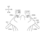
以下、本発明の第1実施形態の自動二輪車1について、図1を用いて説明する。
以下の説明における前後方向は、特に限定しない限り、車両前後方向である。以下の説明における左右方向は、特に限定しない限り、車両左右方向である。以下の説明における上下方向は、特に限定しない限り、車両上下方向である。本願の各図面に示す矢印F、矢印Re、矢印U、矢印D、矢印L、矢印Riは、それぞれ、前方向、後方向、上方向、下方向、左方向、右方向を表す。図1は、水平な路面RSに自動二輪車1が直進可能に直立した状態を示している。本願の図面に示す路面RSは全て水平である。<First Embodiment of the Present Invention>
Hereinafter, the
The front-rear direction in the following description is the vehicle front-rear direction unless otherwise specified. The left-right direction in the following description is the vehicle left-right direction unless otherwise specified. The vertical direction in the following description is the vehicle vertical direction unless otherwise specified. Arrow F, arrow Re, arrow U, arrow D, arrow L, and arrow Ri shown in each drawing of the present application represent forward, backward, upward, downward, leftward, and rightward directions, respectively. FIG. 1 shows a state in which the
自動二輪車1は、ラウンドトレッド面フロントタイヤ2と、ラウンドトレッド面リヤタイヤ4と、中間フレーム30と、フロントフレーム20と、リヤフレーム40と、ラウンドトレッド面リヤタイヤ揺動アクチュエータ60と、ラウンドトレッド面リヤタイヤ揺動制御装置80と、駆動源70とを備える。
The
ラウンドトレッド面フロントタイヤ2は、車両1が直進可能に直立した状態で前方向または後方向に見て円弧状であるトレッド面2aを有する。それにより、ラウンドトレッド面フロントタイヤ2は、上下方向に対して左右方向に傾斜することができる。ラウンドトレッド面リヤタイヤ4は、ラウンドトレッド面フロントタイヤ2から後方向に離れている。ラウンドトレッド面リヤタイヤ4は、車両1が直進可能に直立した状態で前方向または後方向に見て円弧状であるトレッド面4aを有する。それにより、ラウンドトレッド面リヤタイヤ4は、上下方向に対して左右方向に傾斜することができる。
The round tread surface
フロントフレーム20は、ラウンドトレッド面フロントタイヤ2をフロント車軸線A1回りに回転可能に支持する。フロント車軸線A1は、ラウンドトレッド面フロントタイヤ2の中心を通る軸線である。フロントフレーム20は、ラウンドトレッド面フロントタイヤ2がラウンドトレッド面フロントタイヤ揺動軸線A2回りに中間フレーム30に対して揺動可能となるように、ラウンドトレッド面フロントタイヤ揺動軸線A2回りに揺動可能に中間フレーム30に支持される。ラウンドトレッド面フロントタイヤ揺動軸線A2は、後方向に向かうほど上方向に向かう傾きを持つ。
The
リヤフレーム40は、ラウンドトレッド面リヤタイヤ4をリヤ車軸線A3回りに回転可能に支持する。リヤ車軸線A3は、ラウンドトレッド面フロントタイヤ2の中心を通る軸線である。リヤフレーム40は、ラウンドトレッド面リヤタイヤ4がラウンドトレッド面リヤタイヤ揺動軸線A4回りに中間フレーム30に対して揺動可能となるように、ラウンドトレッド面リヤタイヤ揺動軸線A4回りに揺動可能に中間フレーム30に支持される。ラウンドトレッド面リヤタイヤ4がラウンドトレッド面リヤタイヤ揺動軸線A4は、後方向に向かうほど下方向に向かう傾きを持つ。
The
ラウンドトレッド面リヤタイヤ揺動アクチュエータ60は、リヤフレーム40をラウンドトレッド面リヤタイヤ揺動軸線A4回りに中間フレーム30に対して揺動させることで、ラウンドトレッド面リヤタイヤ4をラウンドトレッド面リヤタイヤ揺動軸線A4回りに中間フレーム30に対して揺動させる。ラウンドトレッド面リヤタイヤ揺動制御装置80は、ラウンドトレッド面リヤタイヤ揺動アクチュエータ60を制御する。駆動源70は、ラウンドトレッド面フロントタイヤ2またはラウンドトレッド面リヤタイヤ4に駆動力を付与する。
The round tread surface rear
自動二輪車1は、乗員Oが着座するためのシート10を有する。シート10は、リヤフレーム40に支持される。シート10は、中間フレーム30に支持されてもよい。直進可能に直立した状態の車両1を左方向または右方向に見て、シート10の少なくとも一部は、ラウンドトレッド面リヤタイヤ揺動軸線から上方向に離れている。自動二輪車1は、シート10を有する代わりに、もしくは、シート10に加えて、荷物を載置するための荷台を有してもよい。荷台は、中間フレーム30またはリヤフレーム40に支持される。直進可能に直立した状態の車両1を左方向または右方向に見て、荷台の少なくとも一部は、ラウンドトレッド面リヤタイヤ揺動軸線から上方向に離れている。
The
中間フレーム30、フロントフレーム20、リヤフレーム40、ラウンドトレッド面フロントタイヤ2、ラウンドトレッド面リヤタイヤ4、ラウンドトレッド面リヤタイヤ揺動アクチュエータ60、およびラウンドトレッド面リヤタイヤ揺動制御装置80は、以下の2つの条件を満たすように、形成または配置される。1つ目の条件は、直進可能に直立した状態の車両1を左方向または右方向に見て、ラウンドトレッド面リヤタイヤ揺動軸線A4が、外部から荷重がかかっていない状態の車両1の重心G0とシート10または荷台との間を通ることである。外部から荷重がかかっていない状態の車両1の重心G0は、図1に示す位置に限らない。2つ目の条件は、シート10または荷台にかかる荷重がゼロから増大するにつれて、シート10または荷台に乗載された乗員Oまたは荷物を含む車両1の重心がラウンドトレッド面リヤタイヤ揺動軸線A4に近づくことである。シート10または荷台にかかる荷重がゼロから増大するにつれて、乗員Oまたは荷物を含む車両1の重心は、例えば、図1に示す重心G0から矢印方向に移動する。図1に二点鎖線で示す重心G1は、シート10に着座する乗員Oまたは荷物を含む車両1の重心の一例である。
The
この構成によると、自動二輪車1のシート10または荷台に乗員Oまたは荷物が乗載されたとき、乗員Oまたは荷物を含む車両1の重心G0が、ラウンドトレッド面リヤタイヤ揺動軸線A4に近づくように移動する。乗載荷重の大きさによっては、乗員O等を含む車両1の重心(例えば重心G1)が最終的にラウンドトレッド面リヤタイヤ揺動軸線A4を越えることがある。しかし、乗載荷重が極端に大きくなることはないので、たとえ乗員O等を含む車両1の重心が、ラウンドトレッド面リヤタイヤ揺動軸線A4を越えたとしても、最終的にラウンドトレッド面リヤタイヤ揺動軸線A4から極端に離れることはない。また、乗員O等を含む車両1の重心が最終的にラウンドトレッド面リヤタイヤ揺動軸線A4を越える場合であっても、ラウンドトレッド面リヤタイヤ揺動軸線A4が、荷重がかかっていない状態の車両1の重心G0から上方向に離れている場合に比べると、乗員O等を含む車両1の重心をラウンドトレッド面リヤタイヤ揺動軸線A4に近くなる。
このように、乗員Oまたは荷物を含む車両1の重心(例えば重心G1)がラウンドトレッド面リヤタイヤ揺動軸線A4に近いため、自動二輪車1の乗載荷重の変化に対するラウンドトレッド面リヤタイヤ4の揺動制御の制御性を向上できる。According to this configuration, when the occupant O or the luggage is placed on the
As described above, the center of gravity (for example, the center of gravity G1) of the
自動二輪車1の乗載荷重の変化に対するラウンドトレッド面リヤタイヤ4の揺動制御の制御性が向上するとは、例えば、自動二輪車1の乗載荷重が同じであっても、ラウンドトレッド面リヤタイヤ揺動アクチュエータ60がリヤフレーム40を揺動させるために必要なトルクが抑制されることであってもよい。それにより、自動二輪車1の乗載荷重が増加しても、揺動に必要なトルクの増加を抑えることができる。揺動に必要なトルクが小さいほど、揺動制御が行いやすくなる。また、揺動に必要なトルクを抑えることで、ラウンドトレッド面リヤタイヤ揺動アクチュエータ60を小型化できる。それにより、自動二輪車1を小型化できる。
自動二輪車1の乗載荷重の変化に対するラウンドトレッド面リヤタイヤ4の揺動制御の制御性が向上するとは、例えば、ラウンドトレッド面リヤタイヤ揺動アクチュエータ60の性能が同じであっても、ラウンドトレッド面リヤタイヤ4の揺動制御の応答性が高くなることであってもよい。
自動二輪車1の乗載荷重の変化に対するラウンドトレッド面リヤタイヤ4の揺動制御の制御性が向上するとは、例えば、揺動制御のための制御ロジックを簡素化することであってもよい。具体的には例えば、制御に使用するパラメータが少なくなり、演算処理が簡素化することである。Improving the controllability of the swing control of the round tread surface
Improving the controllability of the swing control of the round tread surface
Improving the controllability of the rocking control of the round tread surface
<本発明の第1実施形態の具体例1>
次に、本発明の第1実施形態の具体例1の自動二輪車1Aについて、図2を用いて説明する。基本的に、本発明の第1実施形態の具体例1は、本発明の第1実施形態の特徴を全て有している。本発明の第1実施形態と同じ部位についての説明は省略する。以下、本発明の第1実施形態で説明していない構成について説明する。<Specific Example 1 of First Embodiment of the Present Invention>
Next, a
自動二輪車1Aは、フロントフレーム20と、中間フレーム30と、リヤフレーム40を有する。フロントフレーム20の主な材質は、アルミニウムや鉄などの金属、CFRPなどの樹脂、または、それらの組み合わせである。中間フレーム30およびリヤフレーム40の主な材質も、同様である。フロントフレーム20、中間フレーム30、およびリヤフレーム40の材質は互いに異なっていてもよい。
The
まず、フロントフレーム20について説明する。フロントフレーム20は、左右一対のフロントサスペンションユニット21、21を有する。フロントサスペンションユニット21は、いわゆるフロントフォークである。フロントサスペンションユニット21は、例えば、テレスコピック式のフロントフォークである。テレスコピック式のフロントフォークは、スプリングと油圧ダンパーを有する。フロントサスペンションユニット21の下端部は、ラウンドトレッド面フロントタイヤ2を回転可能に支持する。フロントサスペンションユニット21は、ラウンドトレッド面フロントタイヤ2が受ける上下方向の振動を吸収するように構成される。
First, the
ラウンドトレッド面フロントタイヤ2は、フロントホイール3の外周部に設置されている。フロントサスペンションユニット21は、フロントホイール3の中央の孔に挿入されるフロント車軸(図示せず)を支持する。それにより、フロントサスペンションユニット21は、ラウンドトレッド面フロントタイヤ2をフロント車軸線A1回りに回転可能に支持する。フロント車軸線A1は、フロント車軸の中心軸線である。自動二輪車1Aが直進可能に直立しているとき、フロント車軸線A1は、左右方向に平行である。
The round tread surface
フロントホイール3には、図示しないフロントブレーキが設置されている。フロントブレーキは、ラウンドトレッド面フロントタイヤ2に制動力を付与可能に構成されている。フロントブレーキの形式は、液圧式、機械式、電気式のいずれであってもよい。フロントブレーキは、例えば、液圧式ディスクブレーキであってもよく、機械式ブレーキの一種であるドラムブレーキであってもよい。
A front brake (not shown) is installed on the
フロントフレーム20は、フロントサスペンションユニット21に加えて、ステアリングシャフト22を有する。ステアリングシャフト22の下部は、フロントサスペンションユニット21の上部に固定されている。ステアリングシャフト22の上部は、ハンドルユニット50に固定されている。
The
次に、中間フレーム30について説明する。中間フレーム30は、その前部に、ヘッドパイプ部31を有する。ヘッドパイプ部31は、円柱状の孔を有する。ステアリングシャフト22は、ヘッドパイプ部31に挿通されている。ステアリングシャフト22とヘッドパイプ部31との間には、図示しない軸受が配置されている。ステアリングシャフト22は、ステアリングシャフト22の中心軸線回りに回転可能にヘッドパイプ部31に支持される。それにより、フロントフレーム20は、ステアリングシャフト22の中心軸線回りに揺動可能に中間フレーム30に支持される。ヘッドパイプ部31の内周面の中心軸線は、ステアリングシャフト22の中心軸線と同軸である。ステアリングシャフト22の中心軸線およびヘッドパイプ部31の内周面の中心軸線が、ラウンドトレッド面フロントタイヤ揺動軸線A2を構成する。ラウンドトレッド面フロントタイヤ揺動軸線A2は、無限に延びる直線である。フロントフレーム20がラウンドトレッド面フロントタイヤ揺動軸線A2回りに揺動可能に中間フレーム30に支持されていることで、ラウンドトレッド面フロントタイヤ2は、ラウンドトレッド面フロントタイヤ揺動軸線A2回りに中間フレーム30に対して揺動可能である。
Next, the
ラウンドトレッド面フロントタイヤ揺動軸線A2は、後方向に向かうほど上方向に向かう傾きを持つ。つまり、ラウンドトレッド面フロントタイヤ揺動軸線A2にある第1の点をラウンドトレッド面フロントタイヤ揺動軸線A2に沿って後方向に移動させた点を第2の点とした場合、第2の点は第1の点より高い位置にある。直進可能に直立した状態の車両1Aを左方向または右方向に見た場合のラウンドトレッド面フロントタイヤ揺動軸線A2の上下方向に対する傾斜角度は、特に限定されない。但し、直進可能に直立した状態の車両1Aを左方向または右方向に見て、ラウンドトレッド面フロントタイヤ揺動軸線A2の上下方向に対する傾斜角度は、45°未満が好ましい。直進可能に直立した状態の車両1Aを左方向または右方向に見て、ラウンドトレッド面フロントタイヤ揺動軸線A2と路面RSとの交点は、ラウンドトレッド面フロントタイヤ2の前端を通り上下方向に平行な直線L11Aと、ラウンドトレッド面フロントタイヤ2の後端を通り上下方向に平行な直線L21Aとの間にある。図2では、ラウンドトレッド面フロントタイヤ揺動軸線A2と路面RSとの交点は、ラウンドトレッド面フロントタイヤ2と路面RSの接点から前方向に若干離れている。ラウンドトレッド面フロントタイヤ揺動軸線A2と路面RSとの交点は、ラウンドトレッド面フロントタイヤ2と路面RSの接点と同じかほぼ同じであってもよい。ラウンドトレッド面フロントタイヤ揺動軸線A2と路面RSとの交点は、直線L11Aと直線L21Aの間であれば、接点よりも後方向に位置していてもよい。The round tread surface front tire swing axis line A2 has an inclination that increases toward the rear side. That is, when the first point on the round tread surface front tire swing axis A2 is moved backward along the round tread surface front tire swing axis A2 as the second point, the second point Is higher than the first point. The inclination angle of the round tread surface front tire swing axis A2 with respect to the up-down direction when the
中間フレーム30は、その後部に、リヤ揺動軸部32を有する。リヤ揺動軸部32は、後斜め下向きに突出している。ヘッドパイプ部31とリヤ揺動軸部32は、一体的に形成されている。中間フレーム30は、一体成形されている。リヤ揺動軸部32の外形は、略円柱状である。リヤ揺動軸部32の後端部に、揺動レバー33が固定されている。揺動レバー33は、リヤ揺動軸部32の外周面から径方向外側に突出する。図2では、揺動レバー33は、リヤ揺動軸部32から下方向に突出しているが、突出方向はこれに限定されない。揺動レバー33は、リヤ揺動軸部32から上方向、右方向、または左方向に突出していてもよい。
The
次に、リヤフレーム40について説明する。リヤフレーム40は、リヤメインフレーム41と、リヤサスペンションユニット42を有する。リヤサスペンションユニット42は、リヤメインフレーム41の後部に接続されている。リヤサスペンションユニット42は、左右一対のスイングアーム43、43と、1つのリヤサスペンション44と、リンク機構45を有する。なお、リヤサスペンションユニット42が有するリヤサスペンション44の数は2つでもよい。スイングアーム43の前部は、左右方向に平行な軸線回りに揺動可能にリヤメインフレーム41の後部に支持される。スイングアーム43の後部は、ラウンドトレッド面リヤタイヤ4を支持する。リヤサスペンション44は、スプリングと油圧ダンパーを有する。リヤサスペンション44の一端は、リヤメインフレーム41に接続されている。リンク機構45は、リヤメインフレーム41と、リヤサスペンション44の他端と、スイングアーム43にそれぞれ、左右方向に平行な軸線回りに揺動可能に接続されている。リンク機構45の具体的な構成は特に限定されない。リヤサスペンションユニット42は、ラウンドトレッド面リヤタイヤ4が受ける上下方向の振動を吸収するように構成される。
Next, the
ラウンドトレッド面リヤタイヤ4は、リヤホイール5の外周部に設置されている。スイングアーム43は、リヤホイール5の中央の孔に挿入されるリヤ車軸(図示せず)を支持する。それにより、リヤサスペンションユニット42は、ラウンドトレッド面リヤタイヤ4をリヤ車軸線A3回りに回転可能に支持する。リヤ車軸線A3は、リヤ車軸の中心軸線である。自動二輪車1Aが直進可能に直立しているとき、リヤ車軸線A3は、左右方向に平行である。
The round tread surface
リヤホイール5には、図示しないリヤブレーキが設置されている。リヤブレーキは、ラウンドトレッド面リヤタイヤ4に制動力を付与可能に構成されている。リヤブレーキの形式は、液圧式、機械式、電気式のいずれであってもよい。リヤブレーキは、例えば、液圧式ディスクブレーキであってもよく、機械式ブレーキの一種であるドラムブレーキであってもよい。リヤブレーキの形式は、フロントブレーキの形式と同じであってもよく、異なっていてもよい。
A rear brake (not shown) is installed on the
リヤメインフレーム41は、その前部に、ボス部41aを有する。ボス部41aは、円柱状の孔を有する。中間フレーム30のリヤ揺動軸部32は、ボス部41aに挿通されている。リヤ揺動軸部32とボス部41aとの間には、図示しない軸受が配置されている。ボス部41aは、ボス部41aの内周面の中心軸線回りに回転可能にリヤ揺動軸部32に支持される。それにより、リヤフレーム40は、ボス部41aの中心軸線回りに揺動可能に中間フレーム30に支持される。リヤ揺動軸部32の外周面の中心軸線は、ボス部41aの内周面の中心軸線と同軸である。ボス部41aの内周面の中心軸線およびリヤ揺動軸部32の中心軸線が、ラウンドトレッド面リヤタイヤ揺動軸線A41Aを構成する。ラウンドトレッド面リヤタイヤ揺動軸線A41Aは、第1実施形態のラウンドトレッド面リヤタイヤ揺動軸線A4の一例である。ラウンドトレッド面リヤタイヤ揺動軸線A41Aは、無限に延びる直線である。リヤフレーム40がラウンドトレッド面リヤタイヤ揺動軸線A41A回りに揺動可能に中間フレーム30に支持されていることで、ラウンドトレッド面リヤタイヤ4は、ラウンドトレッド面リヤタイヤ揺動軸線A41A回りに中間フレーム30に対して揺動可能である。The rear
ラウンドトレッド面リヤタイヤ揺動軸線A41Aは、後方向に向かうほど下方向に向かう傾きを持つ。つまり、ラウンドトレッド面リヤタイヤ揺動軸線A41Aにある第1の点をラウンドトレッド面リヤタイヤ揺動軸線A41Aに沿って後方向に移動させた点を第2の点とした場合、第2の点は第1の点より低い位置にある。直進可能に直立した状態の車両1Aを左方向または右方向に見た場合のラウンドトレッド面リヤタイヤ揺動軸線A41Aの上下方向に対する傾斜角度は、特に限定されない。但し、直進可能に直立した状態の車両1Aを左方向または右方向に見て、ラウンドトレッド面リヤタイヤ揺動軸線A41Aの上下方向に対する傾斜角度は、45°を超えることが好ましい。直進可能に直立した状態の車両1Aを左方向または右方向に見て、ラウンドトレッド面リヤタイヤ揺動軸線A41Aと路面RSとの交点は、ラウンドトレッド面リヤタイヤ4の前端を通り上下方向に平行な直線L31Aと、ラウンドトレッド面リヤタイヤ4の後端を通り上下方向に平行な直線L41Aとの間にある。図2では、ラウンドトレッド面リヤタイヤ揺動軸線A41Aと路面RSとの交点は、ラウンドトレッド面リヤタイヤ4と路面RSの接点よりも後方向に位置する。Round tread surface rear tire pivot axis A4 1A has an inclination toward the downward direction increases toward the rear direction. That is, when the point is moved backward along the first point on the round tread surface rear tire swing axis A4 1A round tread surface rear tire swing axis A4 1A and the second point, the second point Is lower than the first point. The inclination angle of the round tread surface rear tire swing axis A4 1A with respect to the up-down direction when the
リヤフレーム40は、油圧シリンダ60および油圧ポンプ61を支持する。油圧シリンダ60および油圧ポンプ61は、リヤフレーム40と一体的に揺動する。油圧シリンダ60は、中間フレーム30の揺動レバー33の先端部(図2中、下端部)の近傍に配置されている。油圧シリンダ60は、第1実施形態のラウンドトレッド面リヤタイヤ揺動アクチュエータ60の一例である。油圧シリンダ60は、油圧ポンプ61に接続されている。油圧ポンプ61によって加圧されたオイルが、油圧シリンダ60に供給される。油圧シリンダ60は、油圧に応じて直線方向に往復移動するピストンロッド(図示せず)を有する。油圧シリンダ60のピストンロッドは、揺動レバー33の先端部に接続されている。
The
ピストンロッドが直線方向に移動することで、揺動レバー33は、リヤ揺動軸部32の外周面の周方向に揺動する。このように、油圧シリンダ60は、リヤフレーム40をラウンドトレッド面リヤタイヤ揺動軸線A41A回りに中間フレーム30に対して揺動させる。それにより、ラウンドトレッド面リヤタイヤ4が、ラウンドトレッド面リヤタイヤ揺動軸線A41A回りに中間フレーム30に対して揺動する。つまり、油圧シリンダ60(ラウンドトレッド面リヤタイヤ揺動アクチュエータ)は、ラウンドトレッド面リヤタイヤ4をラウンドトレッド面リヤタイヤ揺動軸線A41A回りに中間フレーム30に対して揺動させる。As the piston rod moves in the linear direction, the
リヤフレーム40は、リヤメインフレーム41とリヤサスペンションユニット42に加えて、シートフレーム46を有する。シートフレーム46は、リヤメインフレーム41に固定される。シートフレーム46は、運転者(乗員)が着座するためのシート10と、同乗者(乗員)が着座するためのタンデムシート11を支持する。つまり、シート10およびタンデムシート11は、リヤフレーム40に支持される。タンデムシート11は、シート10の後端よりも後方向に位置する。自動二輪車1Aの乗車定員は、2名である。タンデムシート11は無くてもよい。なお、図2には、車両1Aを右方向に見た場合のシート10の上縁以外のシート10の境界線は表示していない。また、図2には、車両1Aを右方向に見た場合のタンデムシート11の上縁以外のタンデムシート11の境界線は表示していない。シート10の後端は、タンデムシート11の前端とほぼ同じ位置である。直進可能に直立した状態の車両1Aを左方向または右方向に見て、シート10全体が、ラウンドトレッド面リヤタイヤ揺動軸線A41Aから上方向に離れている。直進可能に直立した状態の車両1Aを左方向または右方向に見て、タンデムシート11全体が、ラウンドトレッド面リヤタイヤ揺動軸線A41Aから上方向に離れている。The
リヤフレーム40は、エンジンユニット70を支持する。エンジンユニット70は、第1実施形態の駆動源70の一例である。エンジンユニット70は、ラウンドトレッド面リヤタイヤ4に駆動力を付与可能に構成されている。エンジンユニット70の出力(駆動力)は、チェーンまたはベルトを介して、ラウンドトレッド面リヤタイヤ4に伝達される。エンジンユニット70は、クラッチ機構を含む。エンジンユニット70は、変速機を含んでいてもよく、含んでいなくてもよい。エンジンユニット70が変速機を含んでいない場合、リヤホイール5が変速機を支持する。エンジンユニット70の出力(駆動力)は、変速機を介して、ラウンドトレッド面リヤタイヤ4に伝達される。変速機は、エンジンユニット70の出力軸の回転速度とラウンドトレッド面リヤタイヤ4の回転速度の比を変更できるように構成されている。エンジンユニット70は、4ストロークエンジンでもよく、2ストロークエンジンでもよい。エンジンユニット70は、単気筒エンジンであってもよく、多気筒エンジンであってもよい。エンジンユニット70ユニットが多気筒エンジンの場合、エンジンユニット70は独立スロットル式であることが好ましい。エンジンユニット70は、水冷式エンジンでもよく、強制空冷式エンジンであってもよく、自然空冷式エンジンであってもよい。エンジンユニット70は、過給機を備えた過給エンジンであってもよい。過給機は、燃焼室に供給される空気を圧縮する装置である。過給機は、機械式過給機であってもよく、排気タービン式過給機(いわゆるターボチャージャ)であってもよい。エンジンユニット70は、ガソリンエンジンであってもよく、ディーゼルエンジンであってもよい。エンジンユニット70は、水素ロータリーエンジンであってもよい。
The
リヤフレーム40は、燃料タンク71を支持する。燃料タンク71は、エンジンユニット70に供給される燃料を貯留する。燃料タンク71は、シート10の前端よりも前方向に位置する。燃料タンク71は、エンジンユニット70の上に配置される。燃料タンク71は、自動二輪車1Aの左右方向の中央部にある。つまり、直進可能に直立した状態の車両1Aを下方向に見た場合に、燃料タンク71は、ラウンドトレッド面リヤタイヤ揺動軸線A41Aと重なる。The
自動二輪車1Aは、図示しないバッテリを有する。バッテリは、各種の電気機器に電力を供給する。各種の電気機器は、後述する制御装置80および各種センサを含む。
The
上述したように、自動二輪車1Aは、ハンドルユニット50を有する。ハンドルユニット50は、左グリップ51および右グリップ(図示せず)を有する。左グリップ51および右グリップは、運転者(乗員)の手に把持される。上述したように、ハンドルユニット50は、ステアリングシャフト22に固定される。左右のグリップを把持した運転者がハンドルユニット50を回転させる操作を行うことで、ステアリングシャフト22がラウンドトレッド面フロントタイヤ揺動軸線A2回りに中間フレーム30に対して揺動する。それにより、ラウンドトレッド面フロントタイヤ2は操舵される。つまり、運転者の操作によって、ラウンドトレッド面フロントタイヤ2はラウンドトレッド面フロントタイヤ揺動軸線A2回りに中間フレーム30に対して揺動する。
As described above, the
右グリップは、アクセルグリップである。運転者がアクセルグリップを回すように操作することで、エンジンユニット70(駆動源)の出力が調整される。具体的には、アクセルグリップの操作量に応じて、エンジンユニット70が有するスロットルバルブ(図示せず)の開度が調整される。スロットルバルブの開度に応じて、燃焼室に供給される空気量が変化する。スロットルバルブは、スロットル・バイ・ワイヤ方式で制御される。エンジンユニット70は、アクセル・バイ・ワイヤ方式で制御される。スロットルバルブは、制御装置80に接続される。制御装置80は、アクセルグリップの操作量を検出するアクセルセンサ(図示せず)の検出結果に応じて、スロットルバルブの開度を制御する。つまり、制御装置80は、アクセルグリップの操作量に応じて、エンジンユニット70の出力を制御する。状況によっては、制御装置80は、アクセルグリップの操作に関わらず、スロットルバルブの開度を変更してもよい。なお、スロットルバルブは、スロットルワイヤを介してアクセルグリップに接続されてもよい。
The right grip is the accelerator grip. The output of the engine unit 70 (driving source) is adjusted by the driver operating the accelerator grip so as to rotate it. Specifically, the opening degree of a throttle valve (not shown) included in the
ハンドルユニット50の右部には、フロントブレーキレバー(図示せず)が設けられている。ハンドルユニット50の左部には、リヤブレーキレバー(図示せず)が設けられている。運転者が右グリップを握った手の指でフロントブレーキレバーを引くように操作することで、フロントブレーキが作動して、ラウンドトレッド面フロントタイヤ2に制動力が付与される。運転者が左グリップ51を握った手の指でリヤブレーキレバーを引くように操作することで、リヤブレーキが作動して、ラウンドトレッド面リヤタイヤ4に制動力が付与される。フロントブレーキおよびリヤブレーキは、ブレーキ・バイ・ワイヤ方式で制御される。フロントブレーキおよびリヤブレーキは、制御装置80に接続される。制御装置80は、フロントブレーキレバーの操作量を検出するフロントブレーキセンサ(図示せず)の検出結果に応じて、フロントブレーキを作動させる。制御装置80は、リヤブレーキレバーの操作量を検出するリヤブレーキセンサ(図示せず)の検出結果に応じて、リヤブレーキを作動させる。状況によっては、制御装置80は、ブレーキレバーの操作に関わらず、ブレーキを作動させてもよい。フロントブレーキレバーは、フロントブレーキと機械的に接続されてもよい。リヤブレーキレバーは、リヤブレーキと機械的に接続されてもよい。フロントブレーキレバーまたはリヤブレーキレバーの代わりに、ブレーキペダルを設けてもよい。ブレーキペダルは、運転者の足で操作される。
A front brake lever (not shown) is provided on the right side of the
自動二輪車1Aは、車体カバー12を有する。図2には、車体カバー12の一部を二点鎖線で表示している。車体カバー12は、複数の部品で構成される。車体カバー12は、フロントフレーム20の少なくとも一部と、中間フレーム30と、リヤフレーム40の少なくとも一部を覆う。車体カバー12の少なくとも一部は、リヤフレーム40に支持される。車体カバー12は、図示しないフロントカウルを含む。フロントカウルは、ヘッドパイプ部31を前から覆う。
The
自動二輪車1Aは、ラウンドトレッド面フロントタイヤ2またはラウンドトレッド面リヤタイヤ4の回転速度を検出する車輪速センサ(図示せず)を有する。自動二輪車1Aは、ラウンドトレッド面フロントタイヤ2およびラウンドトレッド面リヤタイヤ4の回転速度をそれぞれ検出する2つの車輪速センサを有していてもよい。制御装置80は、車輪速センサにより検出されたラウンドトレッド面フロントタイヤ2またはラウンドトレッド面リヤタイヤ4の回転速度と、ラウンドトレッド面フロントタイヤ2またはラウンドトレッド面リヤタイヤ4の径に基づいて、自動二輪車1Aの車速を算出する。
The
自動二輪車1Aは、ハンドルユニット50の操舵角を検出するハンドル舵角センサ(図示せず)を有する。ハンドルユニット50の操舵角とは、ステアリングシャフト22の回転角である。
The
自動二輪車1Aは、中間フレーム30の上下方向に対する左右方向への傾きに関連する物理量を検出する傾斜検出装置81を有する。傾斜検出装置81は、中間フレーム30に支持される。中間フレーム30の上下方向に対する左右方向への傾きとは、中間フレーム30が自動二輪車1Aのロール軸回りに揺動することである。ロール軸は、前後方向に平行な軸線である。傾斜検出装置81が検出する上記物理量は、中間フレーム30のロール角、ロールレート、およびロール角加速度の少なくとも1つを含む。傾斜検出装置81は、ロール角、ロールレート、ロール角加速度の少なくとも1つを検出するセンサ(ジャイロセンサ)であってもよい。傾斜検出装置81は、ジャイロセンサの検出結果に基づいて演算処理を行う演算処理部を含んでいてもよい。例えば、傾斜検出装置81は、ジャイロセンサで検出されたロールレートを積分することで、ロール角を算出してもよい。傾斜検出装置81は、センサで検出されたロール角加速度を積分することで、ロールレートを算出してもよい。傾斜検出装置81は、ジャイロセンサで検出されたロール角を微分することで、ロールレートを算出してもよい。傾斜検出装置81は、ジャイロセンサで検出されたロールレートを微分することで、ロール角加速度を算出してもよい。傾斜検出装置81は、ハンドル舵角センサの検出結果などに基づいて演算処理を行う演算処理部であってもよい。傾斜検出装置81は、ハンドルユニット50の操舵角などに基づいて、中間フレーム30のロール角を算出してもよい。傾斜検出装置81は、センサと演算処理部の両方を含んでいてもよい。傾斜検出装置81は、センサを含まず、演算処理部だけで構成されていてもよい。演算処理部は、後述する制御装置80に含まれてもよい。
The
自動二輪車1Aは、中間フレーム30の前後方向に対する左右方向への傾きに関連する物理量を検出する検出装置(図示せず)を有する。中間フレーム30の前後方向に対する左右方向への傾きとは、中間フレーム30が自動二輪車1Aのヨー軸回りに揺動することである。ヨー軸は、上下方向に平行な軸線である。この検出装置が検出する上記物理量は、中間フレーム30のヨー角、ヨーレート、およびヨー角加速度の少なくとも1つを含む。自動二輪車1Aは、中間フレーム30の前後方向に対する上下方向への傾きに関連する物理量を検出する検出装置を有する。中間フレーム30の前後方向に対する上下方向への傾きとは、中間フレーム30が自動二輪車1Aのピッチ軸回りに揺動することである。ピッチ軸は、左右方向に平行な軸線である。この検出装置が検出する上記物理量は、中間フレーム30のピッチ角、ピッチレート、およびピッチ角加速度の少なくとも1つを含む。
The
自動二輪車1Aは、制御装置80を有する。制御装置80は、例えば、CPU(Central Processing Unit)、ROM(Read Only Memory)、RAM(Random Access Memory)などで構成されている。CPUは、ROMやRAMに記憶されたプログラムや各種データに基づいて情報処理を実行する。制御装置80は、中間フレーム30に支持されてもよく、リヤフレーム40に支持されてもよい。制御装置80の位置は、図2に示す位置に限定されない。制御装置80は、アクセルセンサ、フロントブレーキセンサ、リヤブレーキセンサ、車輪速センサ、ハンドル舵角センサ、および傾斜検出装置81などの各種センサに接続される。制御装置80は、これらのセンサから信号を受信する。上述したように、傾斜検出装置81が演算処理部を含む場合は、傾斜検出装置81の演算処理部は制御装置80に含まれてもよい。制御装置80は、燃料供給装置およびスロットルバルブなどのエンジン制御アクチュエータに接続される。制御装置80は、フロントブレーキおよびリヤブレーキのアクチュエータに接続される。制御装置80は、油圧ポンプ61に接続される。制御装置80は、接続されたこれらの機器を制御する。制御装置80は、油圧ポンプ61を介して油圧シリンダ60(ラウンドトレッド面リヤタイヤ揺動アクチュエータ)を制御する。制御装置80は、油圧シリンダ60を制御することで、ラウンドトレッド面リヤタイヤ4の揺動を制御する。制御装置80は、本発明のラウンドトレッド面リヤタイヤ揺動アクチュエータ制御装置を含む。制御装置80によるラウンドトレッド面リヤタイヤ4の揺動制御については後述する。
The
中間フレーム30、フロントフレーム20、リヤフレーム40、ラウンドトレッド面フロントタイヤ2、ラウンドトレッド面リヤタイヤ4、油圧シリンダ60(ラウンドトレッド面リヤタイヤ揺動アクチュエータ)、および制御装置80は、以下の2つの条件を満たすように、形成または配置される。1つ目の条件は、直進可能に直立した状態の車両1Aを左方向または右方向に見て、ラウンドトレッド面リヤタイヤ揺動軸線A41Aが、外部から荷重がかかっていない状態の車両1Aの重心G01Aとシート10との間を通ることである。外部から荷重がかかっていない状態の車両1Aの重心G01Aは、図2に示す位置に限らない。2つ目の条件は、シート10にかかる荷重がゼロから増大するにつれて、シート10に着座する運転者(乗員)を含む車両1Aの重心がラウンドトレッド面リヤタイヤ揺動軸線A41Aに近づくことである。シート10にかかる荷重がゼロから増大するにつれて、運転者(乗員)を含む車両1Aの重心は、例えば、図2に示す重心G01Aから矢印方向に移動する。図2に二点鎖線で示す重心G11Aは、シート10に着座する運転者(乗員)を含む車両1Aの重心の一例である。シート10に着座する運転者(乗員)を含む車両1Aの重心G11Aは、ラウンドトレッド面リヤタイヤ揺動軸線A41Aを越えてもよく、越えなくてもよい。シート10およびタンデムシート11にそれぞれ乗員が着座した場合、2名の乗員を含む車両1Aの重心は、ラウンドトレッド面リヤタイヤ揺動軸線A41Aを越えてもよく、越えなくてもよい。推奨される乗載荷重の上限値を極端に上回らなければ、車両1Aが外部から受ける全ての荷重を含む車両1Aの重心は、ラウンドトレッド面リヤタイヤ揺動軸線A41Aから極端に離れることはない。この構成によると、第1実施形態で述べた効果と同様の効果が得られる。The
車両1Aが直進可能に直立した状態において、油圧シリンダ60(ラウンドトレッド面リヤタイヤ揺動アクチュエータ)は、ラウンドトレッド面リヤタイヤ4およびラウンドトレッド面フロントタイヤ2の両方の上端よりも上方向に位置する。直進可能に直立した状態の車両1Aを左方向または右方向に見て、油圧シリンダ60(ラウンドトレッド面リヤタイヤ揺動アクチュエータ)は、ラウンドトレッド面リヤタイヤ揺動軸線A41Aと重ならない。図2では、直進可能に直立した状態の車両1Aを左方向または右方向に見て、油圧シリンダ60(ラウンドトレッド面リヤタイヤ揺動アクチュエータ)全体が、ラウンドトレッド面リヤタイヤ揺動軸線A41Aから下方向に離れている。In a state in which the
直進可能に直立した状態の車両1Aを左方向または右方向に見て、エンジンユニット70(駆動源)の少なくとも一部は、ラウンドトレッド面リヤタイヤ揺動軸線A41Aから下方向に離れている。図2では、エンジンユニット70(駆動源)全体が、ラウンドトレッド面リヤタイヤ揺動軸線A41Aから下方向に離れている。直進可能に直立した状態の車両1Aを左方向または右方向に見て、フロントサスペンションユニット21の少なくとも一部は、ラウンドトレッド面リヤタイヤ揺動軸線A41Aから下方向に離れている。図2では、フロントサスペンションユニット21全体が、ラウンドトレッド面リヤタイヤ揺動軸線A41Aから下方向に離れている。直進可能に直立した状態の車両1Aを左方向または右方向に見て、リヤサスペンションユニット42の少なくとも一部は、ラウンドトレッド面リヤタイヤ揺動軸線A41Aから下方向に離れている。図2では、リヤサスペンションユニット42の一部が、ラウンドトレッド面リヤタイヤ揺動軸線A41Aから下方向に離れており、リヤサスペンションユニット42の他の部分は、ラウンドトレッド面リヤタイヤ揺動軸線A41Aから上方向に離れている。The
ここで、ラウンドトレッド面リヤタイヤ4を揺動させた時の車両1Aの挙動について説明する。以下の説明において、ラウンドトレッド面リヤタイヤ4が上方向に対して左方向に傾くとは、ラウンドトレッド面リヤタイヤ4の上端が下端に対して相対的に左方向に移動することをいう。車両1Aおよびラウンドトレッド面フロントタイヤ2についても同様の定義が適用される。ラウンドトレッド面リヤタイヤ4が前方向に対して左方向に傾くとは、ラウンドトレッド面リヤタイヤ4の前端が後端に対して相対的に左方向に移動した状態をいう。ラウンドトレッド面フロントタイヤ2についても同様の定義が適用される。また、ラウンドトレッド面フロントタイヤ2が左方向に操舵されるとは、ラウンドトレッド面フロントタイヤ2が前方向に対して左方向に傾くことである。
Here, the behavior of the
図3(a)は、車両1Aが水平な路面RSに直進可能に直立している状態を示す。この状態において、外部から荷重がかかっていない状態の車両1Aの重心G01Aは、自動二輪車1Aの左右方向の中央にある。図3(a)の状態から、ラウンドトレッド面リヤタイヤ4が図3(a)に示す矢印Xの方向に揺動すると、図3(b)に示すように、ラウンドトレッド面リヤタイヤ4は、上方向に対して左方向に傾くと共に、前方向に対して右方向に傾く。矢印Xの方向は、後方向に見て時計回りの方向である。ラウンドトレッド面リヤタイヤ4が上方向に対して左方向に傾くことにより、その後、図3(c)に示すように、車両1Aが上方向に対して左方向に傾く。そのため、車両1Aを下方向に見て、車両1Aの重心G01Aは、ラウンドトレッド面リヤタイヤ揺動軸線A41Aから左方向に離れる。これにより、キャンバースラストが発生する。それに加えて、ラウンドトレッド面リヤタイヤ4が前方向に対して右方向に傾くことで、車両1Aが左旋回する。FIG. 3A shows a state in which the
図4(a)は、車両1Aが上方向に対して左方向に傾いている状態を示す。車両1Aを下方向に見て、車両1Aの重心G01Aは、ラウンドトレッド面リヤタイヤ揺動軸線A41Aから左方向に離れている。この状態から、ラウンドトレッド面リヤタイヤ4が、図4(a)に示す矢印Yの方向に揺動すると、図4(b)に示すように、ラウンドトレッド面リヤタイヤ4は、上方向に対して右方向に傾くと共に、前方向に対して右方向に傾く。矢印Xの方向は、上述の矢印Yの方向と逆方向である。それにより、ラウンドトレッド面フロントタイヤ2とラウンドトレッド面リヤタイヤ4の上方向に対する左右方向の傾きが逆になる。また、車両1Aの重心G01Aは右方向に移動する。その結果、図4(c)に示すように、車両1Aが起き上がる。FIG. 4A shows a state in which the
次に、制御装置80によるラウンドトレッド面リヤタイヤ4の揺動制御について説明する。
制御装置80は、傾斜検出装置81で検出された中間フレーム30の上下方向に対する左右方向への傾きに関連する物理量に基づいて、油圧シリンダ60を制御する。制御装置80は、傾斜検出装置81の検出結果に加えて、他のパラメータに基づいて、ラウンドトレッド面リヤタイヤ4の揺動制御を変更してもよい。例えば、車輪速センサの検出結果に基づいてもよい。例えばハンドル舵角センサの検出結果に基づいてもよい。また、例えば、地図情報に基づいてもよい。また、雨などの天候の情報に基づいてもよい。また、例えば、運転者の技量に基づいてもよい。運転者の技量は、運転者が入力するものであっても、走行状況から制御装置が判定したものであってもよい。また、車種によって、ラウンドトレッド面リヤタイヤ4およびラウンドトレッド面フロントタイヤ2の揺動制御は変更されてもよい。Next, rocking control of the round tread surface
The
制御装置80は、運転者によるハンドルユニット50の操舵をアシストするために、ラウンドトレッド面リヤタイヤ4を揺動させる。具体的には、例えば、運転者がハンドルユニット50を左方向に操舵したときに、制御装置80は、車両1Aが上方向に対して左方向に傾くように、ラウンドトレッド面リヤタイヤ4を揺動させてもよい。また、例えば、車両1Aが左旋回しているときに、制御装置80は、車両1Aの上方向に対する左方向の傾きが大きくなるように、ラウンドトレッド面リヤタイヤ4を揺動させてもよい。それにより、旋回性を向上できる。つまり、旋回半径を小さくすることができる。また、例えば、車両1Aが左旋回しているときに運転者がハンドルユニット50を右方向に操舵した場合に、制御装置80は、車両1Aが起き上るように、ラウンドトレッド面リヤタイヤ4を揺動させてもよい。
The
制御装置80は、車両1Aが横風を受けて傾いている場合に、ラウンドトレッド面リヤタイヤ4を揺動させてもよい。例えば、車両1Aが右から風を受けて左方向に傾斜している場合に、ラウンドトレッド面リヤタイヤ4が上方向に対して左方向に傾く方向に、ラウンドトレッド面リヤタイヤ4を揺動させてもよい。
The
自動二輪車1Aは、運転モードとして、車両1Aの上下方向に対する左右方向の傾きを軽減する傾斜軽減モードを有してもよい。制御装置80は、傾斜軽減モード中に車両1Aが上方向に対して左右方向に傾いた場合に、ラウンドトレッド面リヤタイヤ4を揺動させる。特に低速走行時は、車両1Aが上下方向に対して左右方向に傾きやすい。傾斜軽減モード中のラウンドトレッド面リヤタイヤ4の揺動制御は、低速走行時に限ってもよい。
The
制御装置80は、例えば6km/時以下の低速走行行する際、または、停止中に、車両1Aが自立した状態を維持できるように、ラウンドトレッド面リヤタイヤ4を双方向に交互に揺動させてもよい。例えば、人が車両1Aを押して歩く際に、この制御を行ってもよい。
The
第1実施形態の具体例1は、上述した本発明の実施形態の効果に加えて、以下の効果を奏する。 The specific example 1 of the first embodiment has the following effects in addition to the effects of the embodiment of the present invention described above.
直進可能に直立した状態の車両1Aを左方向または右方向に見て、ラウンドトレッド面リヤタイヤ揺動軸線A41Aと路面RSとの交点が、ラウンドトレッド面リヤタイヤ4の前端を通り上下方向に平行な直線L31Aと、ラウンドトレッド面リヤタイヤ4の後端を通り上下方向に平行な直線L41Aとの間にある。それにより、ラウンドトレッド面リヤタイヤ揺動軸線A41Aと路面RSとの交点が、ラウンドトレッド面リヤタイヤ4の前端を通り上下方向に平行な直線L31Aから前方向に離れている場合に比べて、ラウンドトレッド面リヤタイヤ4を揺動させるために必要なモーメントが小さい。また、ラウンドトレッド面リヤタイヤ揺動軸線A41Aと路面RSとの交点が、ラウンドトレッド面リヤタイヤ4の後端を通り上下方向に平行な直線L41Aから後方向に離れている場合に比べて、ラウンドトレッド面リヤタイヤ4を揺動させるために必要なモーメントが小さい。そのため、ラウンドトレッド面リヤタイヤ4の揺動制御の制御性を向上できる。よって、自動二輪車1Aの乗載荷重の変化に対するラウンドトレッド面リヤタイヤ4の揺動制御の制御性をより向上できる。The
直進可能に直立した状態の車両1Aを左方向または右方向に見て、比較的大きい重量を有するエンジンユニット70(駆動源)の少なくとも一部が、ラウンドトレッド面リヤタイヤ揺動軸線A41Aから下方向に離れている。そのため、シート10に荷重がかかっていない状態の車両1Aの重心G01Aとシート10との間にラウンドトレッド面リヤタイヤ揺動軸線A41Aが位置するレイアウトを、容易に実現できる。The
直進可能に直立した状態の車両1Aを左方向または右方向に見て、比較的大きい重量を有するフロントサスペンションユニット21の少なくとも一部が、ラウンドトレッド面リヤタイヤ揺動軸線A41Aから下方向に離れている。そのため、シート10に荷重がかかっていない状態の車両1Aの重心G01Aとシート10との間にラウンドトレッド面リヤタイヤ揺動軸線A41Aが位置するレイアウトを、容易に実現できる。Looking at the
直進可能に直立した状態の車両1Aを方向または右方向に見て、比較的大きい重量を有するリヤサスペンションユニット42の一部が、ラウンドトレッド面リヤタイヤ揺動軸線A41Aから下方向に離れている。そのため、シート10に荷重がかかっていない状態の車両1Aの重心G01Aとシート10との間にラウンドトレッド面リヤタイヤ揺動軸線A41Aが位置するレイアウトを、容易に実現できる。Look at the
直進可能に直立した状態の車両1Aを下方向に見て、燃料タンク71の一部は、ラウンドトレッド面リヤタイヤ揺動軸線A41Aと重なる。それにより、燃料タンク71内の燃料の重量が変化しても、車両1Aの重心G01Aの位置の変化が少ない。そのため、ラウンドトレッド面リヤタイヤ4の揺動制御の制御性の低下を抑えることができる。The
仮に、傾斜検出装置81がリヤフレーム40に設置される場合、傾斜検出装置81の検出結果から中間フレーム30の傾きを検出するには、リヤフレーム40の中間フレーム30に対する揺動角度等を考慮した補正を行う必要がある。傾斜検出装置81が中間フレーム30に設置されていることにより、求める車両1Aの挙動が得られるようにラウンドトレッド面リヤタイヤ4の揺動制御を行うことが容易になる。よって、自動二輪車1Aの乗載荷重の変化に対するラウンドトレッド面リヤタイヤ4の揺動制御の制御性をより向上できる。
If the
<本発明の第1実施形態の具体例2>
次に、本発明の第1実施形態の具体例2の自動二輪車1Bについて、図5を用いて説明する。基本的に、本発明の第1実施形態の具体例2は、本発明の第1実施形態の特徴を全て有している。本発明の第1実施形態およびその具体例1と同じ部位についての説明は省略する。以下、本発明の第1実施形態の具体例1と異なる構成について説明する。<Specific Example 2 of First Embodiment of the Present Invention>
Next, a
油圧シリンダ60は、リヤフレーム40をラウンドトレッド面リヤタイヤ揺動軸線A41B回りに中間フレーム30に対して揺動させる。ラウンドトレッド面リヤタイヤ揺動軸線A41Bは、第1実施形態のラウンドトレッド面リヤタイヤ揺動軸線A4の一例である。ラウンドトレッド面リヤタイヤ揺動軸線A41Bは、後方向に向かうほど下方向に向かう傾きを持つ。直進可能に直立した状態の車両1Bを左方向または右方向に見て、ラウンドトレッド面リヤタイヤ揺動軸線A41Bと路面RSとの交点は、ラウンドトレッド面リヤタイヤ4と路面RSの接点と同じかほぼ同じである。それにより、第1実施形態の具体例1に比べて、リヤフレーム40を揺動させるトルクがより小さい。そのため、ラウンドトレッド面リヤタイヤ4の揺動制御の制御性を向上できる。よって、自動二輪車1Bの乗載荷重の変化に対するラウンドトレッド面リヤタイヤ4の揺動制御の制御性をより向上できる。The
具体例1と同じく、中間フレーム30、フロントフレーム20、リヤフレーム40、ラウンドトレッド面フロントタイヤ2、ラウンドトレッド面リヤタイヤ4、油圧シリンダ60(ラウンドトレッド面リヤタイヤ揺動アクチュエータ)、および制御装置80は、以下の2つの条件を満たすように、形成または配置される。1つ目の条件は、直進可能に直立した状態の車両1Bを左方向または右方向に見て、ラウンドトレッド面リヤタイヤ揺動軸線A41Bが、外部から荷重がかかっていない状態の車両1Bの重心G01Bとシート10との間を通ることである。外部から荷重がかかっていない状態の車両1Bの重心G01Bは、図5に示す位置に限らない。2つ目の条件は、シート10にかかる荷重がゼロから増大するにつれて、シート10に着座する運転者(乗員)を含む車両1Bの重心がラウンドトレッド面リヤタイヤ揺動軸線A41Bに近づくことである。シート10にかかる荷重がゼロから増大するにつれて、運転者(乗員)を含む車両1Bの重心は、例えば、図5に示す重心G01Bから矢印方向に移動する。図5に二点鎖線で示す重心G11Bは、シート10に着座する運転者(乗員)を含む車両1Bの重心G11Bの一例である。シート10に着座する運転者(乗員)を含む車両1Bの重心G11Bは、ラウンドトレッド面リヤタイヤ揺動軸線A41Bを越えてもよく、越えなくてもよい。シート10およびタンデムシート11にそれぞれ乗員が着座した場合、2名の乗員を含む車両1Bの重心は、ラウンドトレッド面リヤタイヤ揺動軸線A41Bを越えてもよく、越えなくてもよい。Similar to the specific example 1, the
<本発明の第1実施形態の具体例3>
次に、本発明の第1実施形態の具体例3の自動二輪車1Cについて、図6を用いて説明する。基本的に、本発明の第1実施形態の具体例3は、本発明の第1実施形態の特徴を全て有している。本発明の第1実施形態およびその具体例1と同じ部位についての説明は省略する。以下、本発明の第1実施形態の具体例1と異なる構成について説明する。<Specific Example 3 of First Embodiment of the Present Invention>
Next, a motorcycle 1C of Specific Example 3 of the first embodiment of the present invention will be described with reference to FIG. Basically, the specific example 3 of the first embodiment of the present invention has all the features of the first embodiment of the present invention. The description of the same parts as in the first embodiment of the present invention and the first specific example thereof will be omitted. Hereinafter, a configuration different from the first specific example of the first embodiment of the present invention will be described.
油圧シリンダ60は、リヤフレーム40をラウンドトレッド面リヤタイヤ揺動軸線A41C回りに中間フレーム30に対して揺動させる。ラウンドトレッド面リヤタイヤ揺動軸線A41Cは、第1実施形態のラウンドトレッド面リヤタイヤ揺動軸線A4の一例である。ラウンドトレッド面リヤタイヤ揺動軸線A41Cは、後方向に向かうほど下方向に向かう傾きを持つ。直進可能に直立した状態の車両1Cを左方向または右方向に見て、ラウンドトレッド面リヤタイヤ揺動軸線A41Cと路面RSとの交点は、ラウンドトレッド面リヤタイヤ4と路面RSの接点よりも前方向に位置する。但し、具体例1と同じく、ラウンドトレッド面リヤタイヤ揺動軸線A41Cと路面RSとの交点は、ラウンドトレッド面リヤタイヤ4の前端を通り上下方向に平行な直線L31Cと、ラウンドトレッド面リヤタイヤ4の後端を通り上下方向に平行な直線L41Cとの間にある。
具体例1と同じく、中間フレーム30、フロントフレーム20、リヤフレーム40、ラウンドトレッド面フロントタイヤ2、ラウンドトレッド面リヤタイヤ4、油圧シリンダ60(ラウンドトレッド面リヤタイヤ揺動アクチュエータ)、および制御装置80は、以下の2つの条件を満たすように、形成または配置される。1つ目の条件は、直進可能に直立した状態の車両1Cを左方向または右方向に見て、ラウンドトレッド面リヤタイヤ揺動軸線A41Cが、外部から荷重がかかっていない状態の車両1Cの重心G01Cとシート10との間を通ることである。外部から荷重がかかっていない状態の車両1Cの重心G01Cは、図6に示す位置に限らない。2つ目の条件は、シート10にかかる荷重がゼロから増大するにつれて、シート10に着座する運転者(乗員)を含む車両1Cの重心がラウンドトレッド面リヤタイヤ揺動軸線A41Cに近づくことである。シート10にかかる荷重がゼロから増大するにつれて、運転者(乗員)を含む車両1Cの重心は、例えば、図6に示す重心G01Cから矢印方向に移動する。図6に二点鎖線で示す重心G11Cは、シート10に着座する運転者(乗員)を含む車両1Cの重心G11Cの一例である。シート10に着座する運転者(乗員)を含む車両1Cの重心G11Cは、ラウンドトレッド面リヤタイヤ揺動軸線A41Cを越えてもよく、越えなくてもよい。シート10およびタンデムシート11にそれぞれ乗員が着座した場合、2名の乗員を含む車両1Cの重心は、ラウンドトレッド面リヤタイヤ揺動軸線A41Cを越えてもよく、越えなくてもよい。Similar to the specific example 1, the
<本発明の第2実施形態>
次に、本発明の第2実施形態の自動二輪車100Aについて、図7を用いて説明する。基本的に、本発明の第2実施形態は、本発明の第1実施形態の説明で述べた特徴を全て有している。本発明の第1実施形態およびその具体例1と同じ部位についての説明は省略する。以下、本発明の第1実施形態およびその具体例1と異なる構成について説明する。<Second Embodiment of the Present Invention>
Next, a
自動二輪車100Aは、フロントフレーム120と、中間フレーム130と、リヤフレーム140を有する。フロントフレーム120の主な材質は、アルミニウムや鉄などの金属、CFRPなどの樹脂、または、それらの組み合わせである。中間フレーム130およびリヤフレーム140の主な材質も、同様である。フロントフレーム120、中間フレーム130、およびリヤフレーム140の材質は互いに異なっていてもよい。
The
まず、フロントフレーム120について説明する。フロントフレーム120は、左右一対のフロントサスペンションユニット21、21と、フロント揺動軸部122を有する。フロント揺動軸部122は、フロントサスペンションユニット21の上部に固定されている。フロントホイール3には、フロントブレーキ106が設置されている。フロントブレーキ106は、ラウンドトレッド面フロントタイヤ2に制動力を付与可能に構成されている。フロントブレーキ106は、液圧式ディスクブレーキである。フロントブレーキ106は、ブレーキホースを介して、フロントハイドロリックユニット107に接続されている。フロントハイドロリックユニット107は、中間フレーム130に支持される。フロントブレーキ106は、フロントハイドロリックユニット107から供給されるブレーキフルードの圧力で作動する。フロントハイドロリックユニット107は、フロントブレーキ106のブレーキ液圧を制御する。フロントハイドロリックユニット107は、液圧調整モータと液圧調整弁を含む。
First, the
次に、中間フレーム130について説明する。中間フレーム130は、中間メインフレーム131を有する。中間メインフレーム131は、ハンドルユニット50と接続されている。ハンドルユニット50は、中間フレーム130に対して揺動不能である。
Next, the
中間メインフレーム131は、フロント電気モータ162を支持する。フロント電気モータ162は、中間メインフレーム131の前部に収容されている。フロント電気モータ162は、中間フレーム130に固定されている。フロント電気モータ162は、出力軸が双方向に回転可能な電気モータである。フロント電気モータ162は、減速機付モータであってもよい。フロント電気モータ162の出力軸は、前斜め下向きに突出している。フロント電気モータ162の出力軸は、フロントフレーム120のフロント揺動軸部122に固定されている。なお、フロント電気モータ162がフロント揺動軸部122に支持され、フロント電気モータ162の出力軸が中間メインフレーム131に固定されてもよい。
The
フロント電気モータ162の出力軸が回転することで、フロントフレーム120がフロント電気モータ162の出力軸の中心軸線回りに中間フレーム130に対して揺動する。フロント電気モータ162は、本発明のラウンドトレッド面フロントタイヤ揺動アクチュエータに相当する。フロント電気モータ162の出力軸が、ラウンドトレッド面フロントタイヤ揺動軸線A2を構成する。つまり、フロント電気モータ162(ラウンドトレッド面フロントタイヤ揺動アクチュエータ)は、フロントフレーム120をラウンドトレッド面フロントタイヤ揺動軸線A2回りに中間フレーム130に対して揺動させる。ラウンドトレッド面フロントタイヤ揺動軸線A2は、無限に延びる直線である。
When the output shaft of the front
フロントフレーム120は、フロント電気モータ162を介して、中間フレーム130に支持される。フロントフレーム120は、フロント電気モータ162の出力軸の中心軸線回りに揺動可能に、中間フレーム130に支持される。フロントフレーム120がラウンドトレッド面フロントタイヤ揺動軸線A2回りに揺動可能に中間フレーム130に支持されていることで、ラウンドトレッド面フロントタイヤ2は、ラウンドトレッド面フロントタイヤ揺動軸線A2回りに中間フレーム130に対して揺動可能である。
The
ラウンドトレッド面フロントタイヤ揺動軸線A2は、後方向に向かうほど上方向に向かう傾きを持つ。つまり、ラウンドトレッド面フロントタイヤ揺動軸線A2にある第1の点をラウンドトレッド面フロントタイヤ揺動軸線A2に沿って後方向に移動させた点を第2の点とした場合、第2の点は第1の点より高い位置にある。直進可能に直立した状態の車両100Aを左方向または右方向に見た場合のラウンドトレッド面フロントタイヤ揺動軸線A2の上下方向に対する傾斜角度は、特に限定されない。但し、直進可能に直立した状態の車両100Aを左方向または右方向に見て、ラウンドトレッド面フロントタイヤ揺動軸線A2の上下方向に対する傾斜角度は、45°未満が好ましい。直進可能に直立した状態の車両100Aを左方向または右方向に見て、ラウンドトレッド面フロントタイヤ揺動軸線A2と路面RSとの交点は、ラウンドトレッド面フロントタイヤ2の前端を通り上下方向に平行な直線L1100Aと、ラウンドトレッド面フロントタイヤ2の後端を通り上下方向に平行な直線L2100Aとの間にある。図7では、ラウンドトレッド面フロントタイヤ揺動軸線A2と路面RSとの交点は、ラウンドトレッド面フロントタイヤ2と路面RSの接点から前方向に若干離れている。ラウンドトレッド面フロントタイヤ揺動軸線A2と路面RSとの交点は、ラウンドトレッド面フロントタイヤ2と路面RSの接点と同じかほぼ同じであってもよい。ラウンドトレッド面フロントタイヤ揺動軸線A2と路面RSとの交点は、直線L1100Aと直線L2100Aの間であれば、接点よりも後方向に位置していてもよい。The round tread surface front tire swing axis line A2 has an inclination that increases toward the rear side. That is, when the first point on the round tread surface front tire swing axis A2 is moved backward along the round tread surface front tire swing axis A2 as the second point, the second point Is higher than the first point. The inclination angle of the round tread surface front tire swing axis A2 with respect to the up-down direction when the
中間フレーム130は、中間メインフレーム131に加えて、シートフレーム132を有する。シートフレーム132は、中間メインフレーム131に固定される。シートフレーム132は、運転者(乗員)が着座するためのシート10と、同乗者(乗員)が着座するためのタンデムシート11を支持する。つまり、シート10およびタンデムシート11は、中間フレーム130に支持される。タンデムシート11は、シート10の後端よりも後方向に位置する。自動二輪車100Aの乗車定員は、2名である。タンデムシート11は無くてもよい。なお、図7には、車両100Aを右方向に見た場合のシート10の上縁以外のシート10の境界線は表示していない。また、図2には、車両100Aを右方向に見た場合のタンデムシート11の上縁以外のタンデムシート11の境界線は表示していない。シート10の後端は、タンデムシート11の前端とほぼ同じ位置である。直進可能に直立した状態の車両100Aを左方向または右方向に見て、シート10全体が、ラウンドトレッド面リヤタイヤ揺動軸線A4100Aから上方向に離れている。直進可能に直立した状態の車両100Aを左方向または右方向に見て、タンデムシート11全体が、ラウンドトレッド面リヤタイヤ揺動軸線A4100Aから上方向に離れている。The
次に、リヤフレーム140について説明する。リヤフレーム140は、リヤ揺動軸部141と、リヤサスペンションユニット42を有する。リヤサスペンションユニット42は、リヤ揺動軸部141の後部に接続されている。リヤサスペンションユニット42のスイングアーム43の前部は、左右方向に平行な軸線回りに揺動可能にリヤ揺動軸部141の後部に支持される。リヤサスペンションユニット42のリヤサスペンション44の一端は、リヤ揺動軸部141の後部に接続されている。リンク機構45は、リヤ揺動軸部141の後部と、リヤサスペンション44の他端と、スイングアーム43にそれぞれ、左右方向に平行な軸線回りに揺動可能に接続されている。
Next, the
リヤホイール5には、インホイールモータ170とリヤブレーキ108(図示せず)が設置されている。インホイールモータ170は、本発明の駆動源に相当する。インホイールモータ170は、電気モータである。インホイールモータ170は、ラウンドトレッド面リヤタイヤ4に駆動力を付与可能に構成されている。インホイールモータ170は、変速機を含んでいてもよく、含んでいなくてもよい。インホイールモータ170が変速機を含んでいない場合、リヤホイール5が変速機を支持していてもよい。インホイールモータ170の出力(駆動力)は、変速機を介して、ラウンドトレッド面リヤタイヤ4に伝達される。変速機は、インホイールモータ170の出力軸の回転速度とラウンドトレッド面リヤタイヤ4の回転速度の比を変更できるように構成されている。また、変速機は設けられなくてもよい。リヤブレーキ108は、ラウンドトレッド面リヤタイヤ4に制動力を付与可能に構成されている。リヤブレーキ108は、ドラムブレーキである。ドラムブレーキは、摩擦力を利用した機械的ブレーキである。
An in-
リヤ揺動軸部141は、略円筒状である。リヤ揺動軸部141は、リヤ電気モータ160を支持する。リヤ電気モータ160は、リヤ揺動軸部141の前部の内側に配置されている。リヤ電気モータ160は、リヤフレーム140に固定されている。リヤ電気モータ160は、フロント電気モータ162の後端よりも後方向に位置する。リヤ電気モータ160は、出力軸が双方向に回転可能な電気モータである。リヤ電気モータ160は、減速機付モータであってもよい。リヤ電気モータ160の出力軸は、前斜め上向きに突出している。リヤ電気モータ160の出力軸は、中間メインフレーム131に固定されている。なお、リヤ電気モータ160が中間メインフレーム131に支持され、リヤ電気モータ160の出力軸がリヤ揺動軸部141に固定されてもよい。
The rear
リヤ電気モータ160の出力軸が回転することで、リヤフレーム140がリヤ電気モータ160の出力軸の中心軸線回りに中間フレーム130に対して揺動する。言い換えると、リヤ電気モータ160は、出力軸の中心軸線回りにリヤフレーム140を中間フレーム130に対して揺動させる。リヤ電気モータ160は、本発明のラウンドトレッド面リヤタイヤ揺動アクチュエータに相当する。リヤ電気モータ160の出力軸が、ラウンドトレッド面リヤタイヤ揺動軸線A4100Aを構成する。ラウンドトレッド面リヤタイヤ揺動軸線A4100Aは、無限に延びる直線である。As the output shaft of the rear
リヤ揺動軸部141の前端部は、リヤ電気モータ160を介して、中間メインフレーム131に支持される。さらに、リヤ揺動軸部141の後部は、リヤ電気モータ160の出力軸の中心軸線回りに揺動可能に中間メインフレーム131に支持される。このように、リヤフレーム140は、リヤ電気モータ160の出力軸の中心軸線回りに揺動可能に、中間フレーム130に支持される。リヤフレーム140がラウンドトレッド面リヤタイヤ揺動軸線A4100A回りに揺動可能に中間フレーム130に支持されていることで、ラウンドトレッド面リヤタイヤ4は、ラウンドトレッド面リヤタイヤ揺動軸線A4100A回りに中間フレーム130に対して揺動可能である。The front end portion of the rear
ラウンドトレッド面リヤタイヤ揺動軸線A4100Aは、後方向に向かうほど下方向に向かう傾きを持つ。つまり、ラウンドトレッド面リヤタイヤ揺動軸線A4100Aにある第1の点をラウンドトレッド面リヤタイヤ揺動軸線A4100Aに沿って後方向に移動させた点を第2の点とした場合、第2の点は第1の点より低い位置にある。直進可能に直立した状態の車両100Aを左方向または右方向に見た場合のラウンドトレッド面リヤタイヤ揺動軸線A4100Aの上下方向に対する傾斜角度は、特に限定されない。但し、直進可能に直立した状態の車両100Aを左方向または右方向に見て、ラウンドトレッド面リヤタイヤ揺動軸線A4100Aの上下方向に対する傾斜角度は、45°を超えることが好ましい。直進可能に直立した状態の車両100Aを左方向または右方向に見て、ラウンドトレッド面リヤタイヤ揺動軸線A4100Aと路面RSとの交点は、ラウンドトレッド面リヤタイヤ4の前端を通り上下方向に平行な直線L3100Aと、ラウンドトレッド面リヤタイヤ4の後端を通り上下方向に平行な直線L4100Aとの間にある。図7では、ラウンドトレッド面リヤタイヤ揺動軸線A4100Aと路面RSとの交点は、ラウンドトレッド面リヤタイヤ4と路面RSの接点と同じかほぼ同じである。Round tread surface The rear tire swing axis A4 100A has a downward inclination toward the rear. That is, when the point is moved backward along the first point on the round tread surface rear tire swing axis A4 100A round tread surface rear tire swing axis A4 100A and the second point, the second point Is lower than the first point. There is no particular limitation on the inclination angle of the round tread surface rear tire swing axis A4 100A with respect to the vertical direction when the
リヤフレーム140は、リヤ揺動軸部141およびリヤサスペンションユニット42に加えて、バッテリ支持部146を有する。バッテリ支持部146は、リヤ揺動軸部141の下面に固定されている、バッテリ支持部146は、蓄電装置171を支持する。蓄電装置171は、少なくとも1つのバッテリ(二次電池)で構成される。蓄電装置171は、各種の電気機器に電力を供給する。各種の電気機器は、インホイールモータ170、フロント電気モータ162、リヤ電気モータ160、各種センサ、および制御装置80を含む。第2実施形態の蓄電装置171の合計容量は、第1実施形態の具体例1のバッテリ(図示せず)の合計容量よりも大きい。バッテリは、例えば、鉛蓄電池であってもよく、リチウム蓄電池であってもよい。バッテリ支持部146には、錘が設置されていてもよい。錘は、バッテリ支持部146以外の箇所に設けてもよい。錘は、ラウンドトレッド面リヤタイヤ揺動軸線A4100Aから下方向に離れた位置に配置することが好ましい。錘は、リヤフレーム140に設けてもよく、中間フレーム130に設けてもよい。The
上述したように、自動二輪車100Aは、ハンドルユニット50を有する。ハンドルユニット50は、左グリップ51および右グリップ(図示せず)を有する。左グリップ51および右グリップは、運転者(乗員)の手に把持される。左グリップ51および右グリップは、それぞれ、グリップの中心軸線回りに揺動可能である。ハンドルユニット50は、中間フレーム130に固定されている。左グリップ51および右グリップは、中間フレーム130に対して左右方向に移動不能である。そのため、ハンドルユニット50は、第1実施形態のように運転者によって操作されない。つまり、ラウンドトレッド面フロントタイヤ2は、ハンドルユニット50によって操舵されない。
As described above, the
左グリップ51または右グリップには、ステアリングスイッチ(図示せず)が設けられている。ステアリングスイッチは、360°未満回転可能に構成されていてもよく、360°回転可能に構成されていてもよい。ステアリングスイッチは、グリップを把持した手の指で操作される。運転者がステアリングスイッチを回すように操作することで、ラウンドトレッド面フロントタイヤ2およびラウンドトレッド面リヤタイヤ4の少なくとも一方が中間フレーム130に対して揺動して、車両100Aが操舵される。つまり、ラウンドトレッド面フロントタイヤ2およびラウンドトレッド面リヤタイヤ4の操舵は、ステア・バイ・ワイヤ方式で制御される。制御装置80は、ステアリングスイッチの操作量に応じて、フロント電気モータ162およびリヤ電気モータ160の少なくとも一方を作動させる。状況によっては、制御装置80は、ステアリングスイッチの操作に関わらず、フロント電気モータ162およびリヤ電気モータ160の少なくとも一方を作動させる。
A steering switch (not shown) is provided on the
右グリップは、アクセルグリップである。運転者がアクセルグリップを回すように操作することで、インホイールモータ170(駆動源)の出力が調整される。駆動源が電気モータ(インホイールモータ170)であるため、駆動源は、アクセル・バイ・ワイヤ方式で制御される。インホイールモータ170の出力は、制御装置80によって制御される。制御装置80は、アクセルグリップの操作量を検出するアクセルセンサ(図示せず)の検出結果に応じて、インホイールモータ170の出力を制御する。状況によっては、制御装置80は、アクセルグリップの操作に関わらず、インホイールモータ170の出力を変更してもよい。
The right grip is the accelerator grip. By operating the driver to rotate the accelerator grip, the output of the in-wheel motor 170 (driving source) is adjusted. Since the drive source is the electric motor (in-wheel motor 170), the drive source is controlled by the accelerator-by-wire method. The output of the in-
ハンドルユニット50の右部には、フロントブレーキレバー(図示せず)が設けられている。運転者が右グリップを握った手の指でフロントブレーキレバーを引くように操作することで、フロントブレーキ106が作動して、ラウンドトレッド面フロントタイヤ2に制動力が付与される。フロントブレーキ106は、ブレーキ・バイ・ワイヤ方式で制御される。フロントブレーキ106は、制御装置80に接続される。上述したように、フロントブレーキ106は、液圧式ディスクブレーキであって、フロントハイドロリックユニット107に接続される。制御装置80は、フロントブレーキレバーの操作量を検出するフロントブレーキセンサ(図示せず)の検出結果に応じて、フロントハイドロリックユニット107からフロントブレーキ106に供給する液圧を調整する。つまり、制御装置80は、フロントブレーキレバーの操作量に応じて、フロントブレーキ106を作動させる。状況によっては、制御装置80は、フロントブレーキレバーの操作に関わらず、フロントブレーキ106を作動させてもよい。なお、フロントブレーキレバーは、ブレーキホースを介して、フロントハイドロリックユニット107と接続されてもよい。フロントブレーキレバーの代わりに、ブレーキペダルを設けてもよい。ブレーキペダルは、運転者の足で操作される。
A front brake lever (not shown) is provided on the right side of the
ハンドルユニット50の左部には、リヤブレーキレバー(図示せず)が設けられている。運転者が左グリップ51を握った手の指でリヤブレーキレバーを引くように操作することで、リヤブレーキ108が作動して、ラウンドトレッド面リヤタイヤ4に制動力が付与される。リヤブレーキ108は、ブレーキ・バイ・ワイヤ方式で制御される。リヤブレーキ108は、制御装置80に接続される。上述したように、リヤブレーキ108は、ドラムブレーキである。制御装置80は、リヤブレーキレバーの操作量を検出するリヤブレーキセンサ(図示せず)の検出結果に応じて、リヤブレーキ108を作動させる。状況によっては、制御装置80は、リヤブレーキレバーの操作に関わらず、リヤブレーキ108を作動させてもよい。なお、リヤブレーキレバーは、リヤブレーキ108と機械的に接続されてもよい。リヤブレーキレバーの代わりに、ブレーキペダルを設けてもよい。ブレーキペダルは、運転者の足で操作される。
A rear brake lever (not shown) is provided on the left side of the
自動二輪車100Aは、車体カバー112を有する。図7には、車体カバー112の一部を二点鎖線で表示している。車体カバー112は、複数の部品で構成される。車体カバー112は、フロントフレーム120の少なくとも一部と、中間フレーム130と、リヤフレーム140の少なくとも一部を覆う。車体カバー112の少なくとも一部は、リヤフレーム140に支持される。車体カバー112は、図示しないフロントカウルを含む。フロントカウルは、中間メインフレーム131の前面を前から覆う。
The
自動二輪車100Aは、第1実施形態の具体例1と同じく、傾斜検出装置81を有する。傾斜検出装置81は、中間フレーム130に支持される。
The
自動二輪車1Aと異なり、自動二輪車100Aは、運転モードとして、自律運転モードと、手動運転モードを有する。自律運転モードでは、運転者が運転しなくても自動二輪車100Aが目的位置まで自動的に走行する。手動運転モードでは、運転者を能動的に支援する制御が行われてもよい。
Unlike the
自動二輪車100Aは、制御装置80を有する。制御装置80は、中間フレーム130に支持されてもよく、リヤフレーム140に支持されてもよい。制御装置80の位置は、図7に示す位置に限定されない。制御装置80は、アクセルセンサ、フロントブレーキセンサ、リヤブレーキセンサ、車輪速センサ、ハンドル舵角センサ、および傾斜検出装置81などの各種センサに接続される。制御装置80は、これらのセンサから信号を受信する。上述したように、傾斜検出装置81が演算処理部を含む場合は、傾斜検出装置81の演算処理部は制御装置80に含まれてもよい。制御装置80は、インホイールモータ170に接続される。制御装置80は、フロントブレーキおよびリヤブレーキのアクチュエータに接続される。制御装置80は、リヤ電気モータ160およびフロント電気モータ162に接続される。制御装置80は、接続されたこれらの機器を制御する。制御装置80は、リヤ電気モータ160およびフロント電気モータ162を制御することで、ラウンドトレッド面リヤタイヤ4およびラウンドトレッド面フロントタイヤ2の揺動を制御する。制御装置80は、本発明のラウンドトレッド面リヤタイヤ揺動アクチュエータ制御装置およびラウンドトレッド面フロントタイヤ揺動制御装置を含む。制御装置80によるリヤ電気モータ160およびフロント電気モータ162の制御の詳細は後述する。
The
中間フレーム130、フロントフレーム120、リヤフレーム140、ラウンドトレッド面フロントタイヤ2、ラウンドトレッド面リヤタイヤ4、リヤ電気モータ160(ラウンドトレッド面リヤタイヤ揺動アクチュエータ)、および制御装置80は、以下の2つの条件を満たすように、形成または配置される。1つ目の条件は、直進可能に直立した状態の車両100Aを左方向または右方向に見て、ラウンドトレッド面リヤタイヤ揺動軸線A4100Aが、外部から荷重がかかっていない状態の車両100Aの重心G0100Aとシート10との間を通ることである。外部から荷重がかかっていない状態の車両100Aの重心G0100Aは、図7に示す位置に限らない。2つ目の条件は、シート10にかかる荷重がゼロから増大するにつれて、シート10に着座する運転者(乗員)を含む車両100Aの重心がラウンドトレッド面リヤタイヤ揺動軸線A4100Aに近づくことである。シート10にかかる荷重がゼロから増大するにつれて、運転者(乗員)を含む車両100Aの重心は、例えば、図7に示す重心G0100Aから矢印方向に移動する。図7に二点鎖線で示す重心G1100Aは、シート10に着座する運転者(乗員)を含む車両100Aの重心G1100Aの一例である。シート10に着座する運転者(乗員)を含む車両100Aの重心G1100Aは、ラウンドトレッド面リヤタイヤ揺動軸線A4100Aを越えてもよく、越えなくてもよい。シート10およびタンデムシート11にそれぞれ乗員が着座した場合、2名の乗員を含む車両100Aの重心は、ラウンドトレッド面リヤタイヤ揺動軸線A4100Aを越えてもよく、越えなくてもよい。推奨される乗載荷重の上限値を極端に上回らなければ、車両100Aが外部から受ける全ての荷重を含む車両100Aの重心は、ラウンドトレッド面リヤタイヤ揺動軸線A4100Aから極端に離れることはない。この構成によると、実施形態で述べた効果と同様の効果が得られる。The
車両100Aが直進可能に直立した状態において、リヤ電気モータ160(ラウンドトレッド面リヤタイヤ揺動アクチュエータ)は、ラウンドトレッド面リヤタイヤ4およびラウンドトレッド面フロントタイヤ2の両方の上端よりも上方向に位置する。ラウンドトレッド面リヤタイヤ揺動軸線A4100Aは、リヤ電気モータ160(ラウンドトレッド面リヤタイヤ揺動アクチュエータ)を通る。直進可能に直立した状態の車両100Aを左方向または右方向に見て、フロント電気モータ162(ラウンドトレッド面フロントタイヤ揺動アクチュエータ)の少なくとも一部は、ラウンドトレッド面リヤタイヤ揺動軸線A4100Aから下方向に離れている。図7では、フロント電気モータ162全体が、ラウンドトレッド面リヤタイヤ揺動軸線A4100Aから下方向に離れている。In a state in which
直進可能に直立した状態の車両100Aを左方向または右方向に見て、蓄電装置171の少なくとも一部は、ラウンドトレッド面リヤタイヤ揺動軸線A4100Aから下方向に離れている。図7では、蓄電装置171全体が、ラウンドトレッド面リヤタイヤ揺動軸線A4100Aから下方向に離れている。直進可能に直立した状態の車両100Aを左方向または右方向に見て、フロントハイドロリックユニット107の少なくとも一部は、ラウンドトレッド面リヤタイヤ揺動軸線A4100Aから下方向に離れている。図7では、フロントハイドロリックユニット107全体が、ラウンドトレッド面リヤタイヤ揺動軸線A4100Aから下方向に離れている。直進可能に直立した状態の車両100Aを左方向または右方向に見て、フロントサスペンションユニット21の少なくとも一部が、ラウンドトレッド面リヤタイヤ揺動軸線A4100Aから下方向に離れている。図7では、フロントサスペンションユニット21全体が、ラウンドトレッド面リヤタイヤ揺動軸線A4100Aから下方向に離れている。直進可能に直立した状態の車両100Aを左方向または右方向に見て、リヤサスペンションユニット42の少なくとも一部は、ラウンドトレッド面リヤタイヤ揺動軸線A4100Aから下方向に離れている。図7では、リヤサスペンションユニット42の一部が、ラウンドトレッド面リヤタイヤ揺動軸線A4100Aから下方向に離れており、リヤサスペンションユニット42の他の部分は、ラウンドトレッド面リヤタイヤ揺動軸線A4100Aから上方向に離れている。When looking at
次に、制御装置80によるラウンドトレッド面リヤタイヤ4およびラウンドトレッド面フロントタイヤ2の揺動制御について説明する。
制御装置80は、傾斜検出装置81で検出された中間フレーム130の上下方向に対する左右方向への傾きに関連する物理量に基づいて、リヤ電気モータ160とフロント電気モータ162を制御する。制御装置80は、傾斜検出装置81の検出結果に加えて、他のパラメータに基づいて、ラウンドトレッド面リヤタイヤ4およびラウンドトレッド面フロントタイヤ2の揺動制御を変更してもよい。例えば、車輪速センサの検出結果に基づいてもよい。例えばハンドル舵角センサの検出結果に基づいてもよい。また、例えば、地図情報に基づいてもよい。また、雨などの天候の情報に基づいてもよい。また、例えば、運転者の技量に基づいてもよい。運転者の技量は、運転者が入力するものであっても、走行状況から制御装置が判定したものであってもよい。また、車種によって、ラウンドトレッド面リヤタイヤ4およびラウンドトレッド面フロントタイヤ2の揺動制御は変更されてもよい。Next, rocking control of the round tread surface
The
制御装置80は、ステアリングスイッチが操作された場合、または、自律運転モード中に車両100Aを操舵させる場合に、ラウンドトレッド面フロントタイヤ2およびラウンドトレッド面リヤタイヤ4の一方を揺動させる。
具体的には、例えば、車両100Aを左方向に操舵させたい場合、制御装置80は、以下のいずれかの制御を行う。制御装置80は、ラウンドトレッド面フロントタイヤ2が前方向に対して左方向に傾くように、ラウンドトレッド面フロントタイヤ2を揺動させてもよい。制御装置80は、ラウンドトレッド面フロントタイヤ2が前方向に対して右方向に傾くようにラウンドトレッド面フロントタイヤ2を揺動させてから、ラウンドトレッド面フロントタイヤ2が前方向に対して左方向に傾くようにラウンドトレッド面フロントタイヤ2を揺動させてもよい。つまり、いわゆる逆操舵(当て舵)を行ってもよい。制御装置80は、ラウンドトレッド面リヤタイヤ4が上方向に対して左方向に傾くように、ラウンドトレッド面リヤタイヤ4を揺動させてもよい。制御装置80は、ラウンドトレッド面フロントタイヤ2とラウンドトレッド面リヤタイヤ4の両方を上述したように揺動させてもよい。
また、例えば、車両100Aが左旋回している状態から車両100Aを右方向に操舵させたい場合、以下のいずれかの制御を行う。制御装置80は、車両100Aが起き上るように、ラウンドトレッド面リヤタイヤ4を揺動させてもよい。制御装置80は、ラウンドトレッド面フロントタイヤ2が前方向に対して右方向に傾くように、ラウンドトレッド面フロントタイヤ2を揺動させてもよい。制御装置80は、ラウンドトレッド面フロントタイヤ2とラウンドトレッド面リヤタイヤ4の両方を上述したように揺動させてもよい。The
Specifically, for example, when it is desired to steer the
Further, for example, when it is desired to steer the
制御装置80は、車両100Aの旋回中に、車両100Aの上方向に対する左右方向の傾きが大きくなるように、ラウンドトレッド面リヤタイヤ4を揺動させてもよい。それにより、旋回性を向上できる。つまり、旋回半径を小さくできる。
The
制御装置80は、車両100Aが横風を受けて傾いている場合に、ラウンドトレッド面リヤタイヤ4を揺動させてもよい。例えば、車両100Aが右から風を受けて左方向に傾斜している場合に、ラウンドトレッド面リヤタイヤ4が上方向に対して左方向に傾く方向に、ラウンドトレッド面リヤタイヤ4を揺動させてもよい。さらに、制御装置80は、ラウンドトレッド面フロントタイヤ2も揺動させてもよい。
The
自動二輪車100Aは、手動運転モード中に、車両100Aの上下方向に対する左右方向の傾きを軽減する傾斜軽減モードを選択可能でもよい。制御装置80は、傾斜軽減モード中に車両100Aが上方向に対して左右方向に傾いた場合に、ラウンドトレッド面リヤタイヤ4およびラウンドトレッド面フロントタイヤ2の少なくとも一方を揺動させる。特に低速走行時は、車両100Aが上下方向に対して左右方向に傾きやすい。傾斜軽減モード中のラウンドトレッド面リヤタイヤ4の揺動制御は、低速走行時に限ってもよい。制御装置80は、自律運転モードで直進走行中に、車両100Aが上方向に対して左右方向に傾いた場合に、ラウンドトレッド面リヤタイヤ4とラウンドトレッド面フロントタイヤ2の少なくとも一方を揺動させてもよい。
The
制御装置80は、例えば6km/時以下の低速走行する際、または、停止中に、車両100Aが自立した状態を維持できるように、ラウンドトレッド面リヤタイヤ4を双方向に交互に揺動させてもよい。また、ラウンドトレッド面フロントタイヤ2を双方向に交互に揺動させてもよい。ラウンドトレッド面リヤタイヤ4とラウンドトレッド面フロントタイヤ2の両方を揺動させてもよい。例えば、人が車両100Aを押して歩く際に、この制御を行ってもよい。
The
第2実施形態は、第1実施形態および第1実施形態の具体例1と同様の構成については、それぞれ同様の効果を奏する。第2実施形態は、さらに以下の効果を奏する。 The second embodiment has the same effects as those of the first embodiment and the specific example 1 of the first embodiment. The second embodiment further has the following effects.
ラウンドトレッド面フロントタイヤ2のラウンドトレッド面フロントタイヤ揺動軸線A2回りの揺動が、制御装置80によって制御される。したがって、ラウンドトレッド面リヤタイヤ4の揺動と、ラウンドトレッド面フロントタイヤ2の揺動を連動させて行うことができる。そのため、ラウンドトレッド面リヤタイヤ4の揺動制御の制御性を向上できる。よって、自動二輪車100Aの乗載荷重の変化に対するラウンドトレッド面リヤタイヤ4の揺動制御の制御性をより向上できる。
The swing of the round tread surface
ラウンドトレッド面フロントタイヤ2の揺動が制御装置80によって制御されるため、フロントフレーム120に接続されたハンドルを設けなくてよい。この場合、車両100Aのレイアウトの自由度を向上できる。そのため、シート10に荷重がかかっていない状態の車両100Aの重心G0100Aとシート10との間にラウンドトレッド面リヤタイヤ揺動軸線A4100Aが位置するレイアウトを、容易に実現できる。Since the swing of the round tread surface
ラウンドトレッド面フロントタイヤ2の揺動が制御装置80によって制御されるため、ラウンドトレッド面フロントタイヤ2の逆操舵(当て舵)を、制御装置80の制御によって行うことができる。つまり、ラウンドトレッド面フロントタイヤ2がハンドルにより操舵される場合とは異なり、制御装置80は、ラウンドトレッド面フロントタイヤ2の全ての操舵が、逆操舵と順操舵のどちらであるかを把握している。よって、ラウンドトレッド面リヤタイヤ4の揺動と、ラウンドトレッド面フロントタイヤ2の揺動の連動性を高めることができる。
Since the swing of the round tread surface
直進可能に直立した状態の車両100Aを左方向または右方向に見て、比較的大きい重量を有するフロントハイドロリックユニット107の少なくとも一部が、ラウンドトレッド面リヤタイヤ揺動軸線A4100Aから下方向に離れている。そのため、シート10に荷重がかかっていない状態の車両100Aの重心G0100Aとシート10との間にラウンドトレッド面リヤタイヤ揺動軸線A4100Aが位置するレイアウトを、容易に実現できる。When looking at the
直進可能に直立した状態の車両100Aを左方向または右方向に見て、比較的大きい重量を有するインホイールモータ170(駆動源)の少なくとも一部が、ラウンドトレッド面リヤタイヤ揺動軸線A4100Aから下方向に離れている。そのため、シート10に荷重がかかっていない状態の車両100Aの重心G0100Aとシート10との間にラウンドトレッド面リヤタイヤ揺動軸線A4100Aが位置するレイアウトを、容易に実現できる。Looking at the
直進可能に直立した状態の車両100Aを左方向または右方向に見て、比較的大きい重量を有するフロント電気モータ162(ラウンドトレッド面フロントタイヤ揺動アクチュエータ)の少なくとも一部が、ラウンドトレッド面リヤタイヤ揺動軸線A4100Aから下方向に離れている。そのため、シート10に荷重がかかっていない状態の車両100Aの重心G0100Aとシート10との間にラウンドトレッド面リヤタイヤ揺動軸線A4100Aが位置するレイアウトを、容易に実現できる。Looking at the
直進可能に直立した状態の車両100Aを左方向または右方向に見て、比較的大きい重量を有する蓄電装置171の少なくとも一部が、ラウンドトレッド面リヤタイヤ揺動軸線A4100Aから下方向に離れている。そのため、シート10に荷重がかかっていない状態の車両100Aの重心G0100Aとシート10との間にラウンドトレッド面リヤタイヤ揺動軸線A4100Aが位置するレイアウトを、容易に実現できる。Looking at the
シート10は中間フレーム130に支持される。そのため、リヤフレーム140は、シート10に着座する乗員の荷重を受けない。よって、リヤフレーム140がシート10を支持する場合に比べて、リヤ電気モータ160(ラウンドトレッド面リヤタイヤ揺動アクチュエータ)が揺動させる対象の重量が小さい。そのため、ラウンドトレッド面リヤタイヤ4の揺動制御の制御性を向上できる。よって、自動二輪車100Aの乗載荷重の変化に対するラウンドトレッド面リヤタイヤ4の揺動制御の制御性をより向上できる。
The
乗員によって、乗員の重量は異なる。リヤフレーム140がシート10を支持する場合、乗員によって、リヤ電気モータ160(ラウンドトレッド面リヤタイヤ揺動アクチュエータ)が揺動させる対象の重量が変化する。それにより、ラウンドトレッド面リヤタイヤ4の揺動制御が複雑になり難しくなる。特に低速走行時の制御が難しい。
一方、シート10が中間フレーム130に支持される場合、乗員の重量が変化しても、リヤ電気モータ160(ラウンドトレッド面リヤタイヤ揺動アクチュエータ)が揺動させる対象の重量は変化しない。そのため、ラウンドトレッド面リヤタイヤ4の揺動制御の制御性を向上できる。よって、自動二輪車100Aの乗載荷重の変化に対するラウンドトレッド面リヤタイヤ4の揺動制御の制御性をより向上できる。The weight of each occupant varies. When the
On the other hand, when the
自動二輪車100Aの走行中、乗員は重心を移動させる動作をする場合がある。特に、自動二輪車100Aの旋回時に、乗員は重心を左右方向に移動させる動作をする場合がある。リヤフレーム140がシート10を支持する場合、乗員が重心を移動させる動作を行うと、リヤ電気モータ160(ラウンドトレッド面リヤタイヤ揺動アクチュエータ)が揺動させる対象の重心が変化する。それにより、ラウンドトレッド面リヤタイヤ4の揺動制御が複雑になり難しくなる。特に低速走行時の制御が難しい。
一方、シート10または荷台が中間フレーム130に支持される場合、乗員が重心を移動させる動作を行っても、リヤ電気モータ160(ラウンドトレッド面リヤタイヤ揺動アクチュエータ)が揺動させる対象の重心は変化しない。そのため、ラウンドトレッド面リヤタイヤ4の揺動制御の制御性を向上できる。よって、自動二輪車100Aの乗載荷重の変化に対するラウンドトレッド面リヤタイヤ4の揺動制御の制御性をより向上できる。While the
On the other hand, when the
リヤフレーム140が中間フレーム130に対して揺動するとき、中間フレーム130はリヤフレーム140よりも姿勢の変化が少ない。シート10は中間フレーム130に支持される。そのため、シート10がリヤフレーム140に支持される場合に比べて、乗員の姿勢を安定させることができる。
When the
比較的大きい重量を有するフロントハイドロリックユニット107が中間フレーム130に支持される。よって、リヤフレーム140がハイドロリックユニットを支持する場合に比べて、リヤ電気モータ160(ラウンドトレッド面リヤタイヤ揺動アクチュエータ)が揺動させる対象の重量が小さい。そのため、ラウンドトレッド面リヤタイヤ4の揺動制御の制御性を向上できる。よって、自動二輪車100Aの乗載荷重の変化に対するラウンドトレッド面リヤタイヤ4の揺動制御の制御性をより向上できる。
The front
比較的大きい重量を有するインホイールモータ170(駆動源)が中間フレーム130に支持される。よって、リヤフレーム140が駆動源を支持する場合に比べて、リヤ電気モータ160(ラウンドトレッド面リヤタイヤ揺動アクチュエータ)が揺動させる対象の重量が小さい。そのため、ラウンドトレッド面リヤタイヤ4の揺動制御の制御性を向上できる。よって、自動二輪車100Aの乗載荷重の変化に対するラウンドトレッド面リヤタイヤ4の揺動制御の制御性をより向上できる。
An in-wheel motor 170 (driving source) having a relatively large weight is supported by the
比較的大きい重量を有する蓄電装置171が中間フレーム130に支持される。よって、リヤフレーム140が蓄電装置171を支持する場合に比べて、リヤ電気モータ160(ラウンドトレッド面リヤタイヤ揺動アクチュエータ)が揺動させる対象の重量が小さい。そのため、ラウンドトレッド面リヤタイヤ4の揺動制御の制御性を向上できる。よって、自動二輪車100Aの乗載荷重の変化に対するラウンドトレッド面リヤタイヤ4の揺動制御の制御性をより向上できる。
<本発明の第2実施形態の変更例1>
次に、本発明の第2実施形態の変更例1の自動二輪車100Bについて、図8を用いて説明する。基本的に、本発明の第2実施形態の変更例1は、本発明の第1実施形態の説明で述べた特徴を全て有している。本発明の第1実施形態、第1実施形態の具体例1、および、第2実施形態と同じ部位についての説明は省略する。以下、第2実施形態と異なる構成について説明する。<
Next, a
リヤ電気モータ160は、リヤフレーム140をラウンドトレッド面リヤタイヤ揺動軸線A4100B回りに中間フレーム130に対して揺動させる。ラウンドトレッド面リヤタイヤ揺動軸線A4100Bは、後方向に向かうほど下方向に向かう傾きを持つ。直進可能に直立した状態の車両100Bを左方向または右方向に見て、ラウンドトレッド面リヤタイヤ揺動軸線A4100Bと路面RSとの交点は、ラウンドトレッド面リヤタイヤ4と路面RSの接点よりも後方向に位置する。但し、第2実施形態と同じく、ラウンドトレッド面リヤタイヤ揺動軸線A4100Bと路面RSとの交点は、ラウンドトレッド面リヤタイヤ4の前端を通り上下方向に平行な直線L3100Bと、ラウンドトレッド面リヤタイヤ4の後端を通り上下方向に平行な直線L4100Bとの間にある。The rear
中間フレーム130、フロントフレーム120、リヤフレーム140、ラウンドトレッド面フロントタイヤ2、ラウンドトレッド面リヤタイヤ4、リヤ電気モータ160(ラウンドトレッド面リヤタイヤ揺動アクチュエータ)、および制御装置80は、以下の2つの条件を満たすように、形成または配置される。1つ目の条件は、直進可能に直立した状態の車両100Bを左方向または右方向に見て、ラウンドトレッド面リヤタイヤ揺動軸線A4100Bが、外部から荷重がかかっていない状態の車両100Bの重心G0100Bとシート10との間を通ることである。外部から荷重がかかっていない状態の車両100Bの重心G0100Bは、図8に示す位置に限らない。2つ目の条件は、シート10にかかる荷重がゼロから増大するにつれて、シート10に着座する運転者(乗員)を含む車両100Bの重心がラウンドトレッド面リヤタイヤ揺動軸線A4100Bに近づくことである。シート10にかかる荷重がゼロから増大するにつれて、運転者(乗員)を含む車両100Bの重心は、例えば、図8に示す重心G0100Bから矢印方向に移動する。図8に二点鎖線で示す重心G1100Bは、シート10に着座する運転者(乗員)を含む車両100Bの重心の一例である。シート10に着座する運転者(乗員)を含む車両100Bの重心G1100Bは、ラウンドトレッド面リヤタイヤ揺動軸線A4100Bを越えてもよく、越えなくてもよい。シート10およびタンデムシート11にそれぞれ乗員が着座した場合、2名の乗員を含む車両100Bの重心は、ラウンドトレッド面リヤタイヤ揺動軸線A4100Bを越えてもよく、越えなくてもよい。The
<本発明の第2実施形態の変更例2>
次に、本発明の第2実施形態の変更例2の自動二輪車100Cについて、図9を用いて説明する。基本的に、本発明の第2実施形態の変更例2は、本発明の第1実施形態の説明で述べた特徴を全て有している。本発明の第1実施形態、第1実施形態の具体例1、および、第2実施形態と同じ部位についての説明は省略する。以下、第2実施形態と異なる構成について説明する。<
Next, a
リヤ電気モータ160は、リヤフレーム140をラウンドトレッド面リヤタイヤ揺動軸線A4100C回りに中間フレーム130に対して揺動させる。ラウンドトレッド面リヤタイヤ揺動軸線A4100Cは、後方向に向かうほど下方向に向かう傾きを持つ。直進可能に直立した状態の車両100Cを左方向または右方向に見て、ラウンドトレッド面リヤタイヤ揺動軸線A4100Cと路面RSとの交点は、ラウンドトレッド面リヤタイヤ4と路面RSの接点よりも前方向に位置する。但し、第2実施形態と同じく、ラウンドトレッド面リヤタイヤ揺動軸線A4100Cと路面RSとの交点は、ラウンドトレッド面リヤタイヤ4の前端を通り上下方向に平行な直線L3100Cと、ラウンドトレッド面リヤタイヤ4の後端を通り上下方向に平行な直線L4100Cとの間にある。The rear
第2実施形態と同じく、中間フレーム130、フロントフレーム120、リヤフレーム140、ラウンドトレッド面フロントタイヤ2、ラウンドトレッド面リヤタイヤ4、リヤ電気モータ160(ラウンドトレッド面リヤタイヤ揺動アクチュエータ)、および制御装置80は、以下の2つの条件を満たすように、形成または配置される。1つ目の条件は、直進可能に直立した状態の車両100Cを左方向または右方向に見て、ラウンドトレッド面リヤタイヤ揺動軸線A4100Cが、外部から荷重がかかっていない状態の車両100Cの重心G0100Cとシート10との間を通ることである。外部から荷重がかかっていない状態の車両100Cの重心G0100Cは、図9に示す位置に限らない。2つ目の条件は、シート10にかかる荷重がゼロから増大するにつれて、シート10に着座する運転者(乗員)を含む車両100Cの重心がラウンドトレッド面リヤタイヤ揺動軸線A4100Cに近づくことである。シート10にかかる荷重がゼロから増大するにつれて、運転者(乗員)を含む車両100Cの重心は、例えば、図9に示す重心G0100Cから矢印方向に移動する。図9に二点鎖線で示す重心G1100Cは、シート10に着座する運転者(乗員)を含む車両100Cの重心G1100Cの一例である。シート10に着座する運転者(乗員)を含む車両100Cの重心G1100Cは、ラウンドトレッド面リヤタイヤ揺動軸線A4100Cを越えてもよく、越えなくてもよい。シート10およびタンデムシート11にそれぞれ乗員が着座した場合、2名の乗員を含む車両100Cの重心は、ラウンドトレッド面リヤタイヤ揺動軸線A4100Cを越えてもよく、越えなくてもよい。Similar to the second embodiment, the
<本発明の第2実施形態の変更例3>
次に、本発明の第2実施形態の変更例3の自動二輪車100Dについて、図10〜図17を用いて説明する。基本的に、本発明の第2実施形態の変更例3は、本発明の第1実施形態の説明で述べた特徴を全て有している。本発明の第1実施形態、第1実施形態の具体例1、および、第2実施形態と同じ部位についての説明は省略する。以下、第2実施形態と異なる構成について説明する。なお、図10、図11および図12のフロントホイール3およびリヤホイール5は、スポーク等の形状を省略して表示している。<
Next, a
図10、図11および図13に示すように、自動二輪車100Dは、フロントフレーム120、中間フレーム230、リヤフレーム140を有する。フロントフレーム120は、自動二輪車100Aと同じく、左右一対のフロントサスペンションユニット21、21と、フロント揺動軸部122を有する。中間フレーム230は、中間メインフレーム131と、シートフレーム132と、可動バックフレーム233を有する。リヤフレーム140は、自動二輪車100Aと同じく、リヤ揺動軸部141と、リヤサスペンションユニット42と、バッテリ支持部146を有する。
As shown in FIGS. 10, 11 and 13, the
自動二輪車100Aと同じく、フロントフレーム120は、フロント電気モータ162を介して中間フレーム230に支持される。自動二輪車100Aと同じく、フロント電気モータ162によって、フロントフレーム120およびラウンドトレッド面フロントタイヤ2は、ラウンドトレッド面フロントタイヤ揺動軸線A2回りに中間フレーム230に対して揺動される。自動二輪車100Aと同じく、リヤフレーム140は、リヤ電気モータ160を介して中間フレーム230に支持される。自動二輪車100Aと同じく、リヤ電気モータ160によって、リヤフレーム140およびラウンドトレッド面リヤタイヤ4は、ラウンドトレッド面リヤタイヤ揺動軸線A4100A回りに中間フレーム230に対して揺動される。As with the
フロントフレーム120のフロントサスペンションユニット21の長手方向に直交する断面は、前後方向に細長い略楕円状である。フロントフレーム120の前部には、フロントフェンダー213が取り付けられている。フロントフェンダー213は、フロントフレーム120には含まれない。フロントフェンダー213は、ラウンドトレッド面フロントタイヤ2の上部のトレッド面2aを覆っている。
A cross section of the
リヤフレーム140のバッテリ支持部146に支持される蓄電装置171は、6つのバッテリで構成される。6つのバッテリは、左右に3つずつ配置されている。また、バッテリ支持部146には錘(図示せず)が設置されている。錘は、バッテリ支持部146の下部に配置される。なお、錘はバッテリ支持部146に設置されなくてもよい。
中間メインフレーム131は、リヤフレーム140のリヤ揺動軸部141の外周面の上部を覆う。中間メインフレーム131は、リヤ揺動軸部141の前部と後部をそれぞれ1周にわたって覆う。中間メインフレーム131は、モノコック構造の車体フレームである。
The intermediate
図12に示すように、中間フレーム230のシートフレーム132は、中間メインフレーム131に固定されている。シートフレーム132の上部は、シートフレームカバー214で覆われている。シートフレームカバー214の後部の上面には、運転者Oが着座するためのシート210が設置されている。つまり、シートフレーム132は、シート210を支持する。シート210は、弾性を有するシート状の部材である。
As shown in FIG. 12, the
図11および図12に示すように、中間フレーム230の可動バックフレーム233は、シートフレーム132の後端部に接続されている。可動バックフレーム233は、左右方向に平行な軸線回りに揺動可能にシートフレーム132に接続されている。運転中を含む通常時、可動バックフレーム233は図11および図12に実線で示す位置に配置される。運転者O(乗員)が乗り降りする際にのみ、可動バックフレーム233は図12に二点鎖線で示す位置に配置される。図10および図13に示すように、可動バックフレーム233は、略V字状の部分を有する。このV字状の部分の間に運転者Oの胴体が配置される。自動二輪車100Dの乗車定員は、1名である。
As shown in FIGS. 11 and 12, the
図11に示すように、ヘッド部235が中間メインフレーム131の上部に接続されている。ヘッド部235は、中間フレーム230に含まれない。図10に示すように、ヘッド部235は、ヘッド底部236と、ヘッドカバー237を有する。ヘッドカバー237は、ヘッド底部236の上面を覆っている。ヘッド底部236とヘッドカバー237との間には、機器等が配置される空間が形成されている。ヘッドカバー237の後部の上面には、クッション材216が設置されている。クッション材216は、弾性を有するシート状の部材である。シート210に着座する運転者Oの姿勢によっては、運転者Oの胴体の前面がクッション材216に接触する。ヘッド底部236は、3つのアーム234a、234a、234cによって中間フレーム230に接続されている。ヘッド部235は、前後方向に移動可能に中間メインフレーム131に接続されている。図示しないスイッチを操作することで、ヘッド底部236は、例えば電気モータ等で前後方向に移動される。この構成により、ヘッド部235の位置を、運転者Oの体格に合わせた位置に調整できる。また、ヘッド部235の位置を変更することで、車両100Dの重心G0100Dの位置を調整できる。As shown in FIG. 11, the
図13に示すように、ヘッド部235は、左グリップ251と右グリップ252を有する。図11に示すように、左グリップ251および右グリップ252は、ヘッド底部236の側部から突出している。右グリップ252および左グリップ251は、ヘッド部235に固定されている。右グリップ252および左グリップ251は、回転不能(揺動不能)である。右グリップ252および左グリップ251は、運転者O(乗員)の手に把持される。
As shown in FIG. 13, the
図14に示すように、左グリップ251の後面には、ステアリングスイッチ253が設けられている。ステアリングスイッチ253は、360°未満回転可能に構成されていてもよく、360°回転可能に構成されていてもよい。ステアリングスイッチ253は、円弧状または円形状の操作面を有する。ステアリングスイッチ253の回転軸線は、左グリップ251の長手方向と略平行である。なお、ステアリングスイッチ253は、360度以上回転可能であって、円盤状の操作面を有していてもよい。ステアリングスイッチ253は、左グリップ251を把持した手の指で操作される。自動二輪車100Aと同じく、運転者Oがステアリングスイッチ253を回すように操作することで、ラウンドトレッド面フロントタイヤ2およびラウンドトレッド面リヤタイヤ4の少なくとも一方が中間フレーム230に対して揺動する。制御装置(図示せず)は、ステアリングスイッチ253の操作量に応じて、フロント電気モータ162およびリヤ電気モータ160の少なくとも一方を作動させる。状況によっては、制御装置は、ステアリングスイッチ253の操作に関わらず、フロント電気モータ162およびリヤ電気モータ160の少なくとも一方を作動させる。
As shown in FIG. 14, a
図15に示すように、右グリップ252の前面には、アクセルレバー254が設けられている。運転者Oがアクセルレバー254を引くように操作することで、インホイールモータ170(駆動源)の出力が調整される。制御装置は、アクセルレバー254の操作量を検出するアクセルセンサ(図示せず)の検出結果に応じて、インホイールモータ170の出力を調整する。状況によっては、制御装置は、アクセルレバー254の操作に関わらず、インホイールモータ170の出力を変更してもよい。
As shown in FIG. 15, an
図15に示すように、左グリップ251には、ブレーキレバー255が設けられている。運転者Oが左グリップ251を握った手の指でブレーキレバー255を引くように操作することで、フロントブレーキ106とリヤブレーキ108の少なくとも一方が作動する。それにより、ラウンドトレッド面フロントタイヤ2およびラウンドトレッド面リヤタイヤ4の少なくとも一方に制動力が付与される。自動二輪車100Aと異なり、フロントブレーキ106とリヤブレーキ108は、1つのブレーキレバー255で操作される。なお、自動二輪車100Dは、フロントブレーキ106とリヤブレーキ108を独立して操作するための2つのブレーキ操作部を有していてもよい。制御装置は、ブレーキレバー255の操作量を検出するブレーキセンサ(図示せず)の検出結果に応じて、フロントブレーキ106およびリヤブレーキ108の少なくとも一方を作動させる。状況によっては、制御装置は、ブレーキレバー255の操作に関わらず、フロントブレーキ106およびリヤブレーキ108の少なくとも一方を作動させてもよい。
As shown in FIG. 15, the
図10および図13に示すように、ヘッド部235の前部は、二股状である。図15に示すように、ヘッド部235の前左部と前右部に、それぞれ、プロジェクター256a、256bが設けられている。図12に示すように、プロジェクター256a、256bは、運転者Oのヘルメットのバイザーに画像を投影する。画像が投影されるバイザーは、ヘルメットのシールドの内側に配置されるインナーバイザーであってもよく、シールドの外側に配置されるアウターバイザーであってもよい。プロジェクター256a、256bから放射される光の放射角度は、スイッチ等で調整可能となっていてもよい。図16は、バイザーに投影される画像の一例を示している。投影画像は、例えば、車速、走行距離、蓄電装置の残量、警告、運転モード、時刻、地図、ナビゲーションの指示などの情報を含む。なお、プロジェクター256a、256bの数は1つだけでもよい。その場合、プロジェクター256a、256bは、左右どちらかに設けられてもよく、中央に設けられてもよい。
As shown in FIGS. 10 and 13, the front portion of the
図15に示すように、ヘッド部235の前部の中央には、2つのカメラ257a、257bが設けられている。カメラ257a、257bは、自動二輪車100Dの前を撮影する。カメラ257aとカメラ257aの一方は、広角レンズを有する広角カメラであり、他方は、望遠レンズを有する望遠カメラである。
As shown in FIG. 15, two
図10、図11および図13に示すように、中間メインフレーム131の後部に、左右一対のフットレストアーム217、217が接続されている。フットレストアーム217の先端部が、運転者Oの足を載せるためのフットレストを構成している。
As shown in FIGS. 10, 11, and 13, a pair of left and
図10および図11に示すように、中間メインフレーム131の後左部に、サイドスタンド219が接続されている。サイドスタンド219は、図11に実線で示す格納状態と、図11に二点鎖線で示す起立状態に切り換え可能である。自動二輪車100Dの駐車時、サイドスタンド219は起立状態で路面に接地される。図17に示すように、起立状態のサイドスタンド219によって、自動二輪車100Dは上下方向に対して左方向に傾いた状態で自立する。
As shown in FIGS. 10 and 11, a
図11に示す符号Greは、リヤ電気モータ160によってラウンドトレッド面リヤタイヤ揺動軸線A4100A回りに中間フレーム230に対して揺動される対象全体の重心である。この重心Greを、リヤ揺動重心Greと称する。直進可能に直立した状態の車両100Dを左方向または右方向に見て、リヤ揺動重心Greは、ラウンドトレッド面リヤタイヤ揺動軸線A4100Aから下方向に離れている。直進可能に直立した状態の車両100Dを左方向または右方向に見て、リヤ揺動重心Greは、外部から荷重がかかっていない状態の自動二輪車100Dの重心G0100Dよりも下方向に位置する。直進可能に直立した状態の車両100Dを左方向または右方向に見て、リヤ揺動重心Greは、外部から荷重がかかっていない状態の自動二輪車100Dの重心G0100Dよりも後方向に位置する。Reference numeral Gre shown in FIG. 11 is the center of gravity of the entire object which is swung by the rear
第1実施形態の具体例1と同じく、中間フレーム230、フロントフレーム120、リヤフレーム140、ラウンドトレッド面フロントタイヤ2、ラウンドトレッド面リヤタイヤ4、リヤ電気モータ160(ラウンドトレッド面リヤタイヤ揺動アクチュエータ)、および制御装置(図示せず)は、以下の2つの条件を満たすように、形成または配置される。1つ目の条件は、直進可能に直立した状態の車両100Dを左方向または右方向に見て、ラウンドトレッド面リヤタイヤ揺動軸線A4100Aが、外部から荷重がかかっていない状態の車両100Dの重心G0100Dとシート210との間を通ることである。外部から荷重がかかっていない状態の車両100Dの重心G0100Dは、図11に示す位置に限らない。2つ目の条件は、シート210にかかる荷重がゼロから増大するにつれて、シート210に着座する運転者Oを含む車両100Dの重心がラウンドトレッド面リヤタイヤ揺動軸線A4100Aに近づくことである。シート210にかかる荷重がゼロから増大するにつれて、運転者Oを含む車両100Dの重心は、例えば、図11に示す重心G0100Dから矢印方向に移動する。シート210に着座する運転者Oを含む車両100Dの重心は、ラウンドトレッド面リヤタイヤ揺動軸線A4100Aを越えてもよく、越えなくてもよい。Similar to the first specific example of the first embodiment, the
制御装置は、自動二輪車100Aの制御装置80とほぼ同じ構成である。制御装置(図示せず)は、中間フレーム230に支持されてもよく、リヤフレーム140に支持されてもよい。制御装置は、制御装置80と同様に、各種センサおよび各種アクチュエータに接続される。さらに、制御装置は、プロジェクター256a、256bおよびカメラ257a、257bに接続される。
The control device has substantially the same configuration as the
上述したように、サイドスタンド219によって自動二輪車100Dは左方向に傾斜した状態で自立する(図17参照)。制御装置は、この状態から、サイドスタンド219によらずに自動二輪車100Dを直立状態で自立させるように、リヤ電気モータ160を制御する。この制御は、運転者Oが自動二輪車100Dに乗車していない状態で行うことが好ましい。この制御は、運転者Oが乗車している状態で行ってもよい。制御装置は、リヤフレーム140の揺動の反動を利用して、自動二輪車100Dを起き上がらせる。以下、より詳細に説明する。
As described above, the side stand 219 causes the
リヤ電気モータ160は、リヤ揺動重心Greが一旦右方向に揺動してから左方向に揺動するように制御される。上述したように、リヤ揺動重心Greは、リヤ電気モータ160によってラウンドトレッド面リヤタイヤ揺動軸線A4100A回りに中間フレーム230に対して揺動される対象全体の重心である。リヤ揺動重心Greを右方向に揺動させるときのラウンドトレッド面リヤタイヤ揺動軸線A4100A回りの回転角度は、自動二輪車100Dを起き上がらせることができる角度であれば、特に限定されない。リヤ揺動重心Greを右方向に揺動させるときのリヤ電気モータ160によるラウンドトレッド面リヤタイヤ揺動軸線A4100A回りの回転角度は、リヤ揺動重心Greを左方向に揺動させるときのリヤ電気モータ160によるラウンドトレッド面リヤタイヤ揺動軸線A4100A回りの回転角度と同じであってもよく、それより大きくてもよい。リヤ揺動重心Greを右方向に揺動させる速度は、特に限定されない。一方、自動二輪車100Dを起き上がらせるためには、リヤ揺動重心Greを左方向に揺動させる速度はある程度の速さが必要である。このように、乗員が車両100Dを支えなくても車両100Dを起き上がらせることができるため、自動二輪車100Dの利便性を向上できる。また、サイドスタンド219は中間フレーム130に支持されるため、リヤフレーム140の揺動をサイドスタンド219が妨げない。The rear
制御装置は、自動二輪車100Dを起き上がらせた後、サイドスタンド219を起立状態から格納状態に切り換える。なお、サイドスタンド219の起立状態から格納状態への切り換えは、足の操作でも行うことができてよい。また、サイドスタンド219の格納状態から起立状態への切り換えは、制御装置によって行われてもよく、足の操作で行われてもよく、その両方が可能であってもよい。
After raising the
制御装置は、顔認識部とジェスチャー認識部を有する。顔認識部およびジェスチャー認識部は、RAMやROMに格納されたプログラムがCPUで実行されることにより実現される機能部である。顔認識部は、カメラ257aおよびカメラ257bの少なくとも一方で撮影された画像の顔を、予め登録された画像の顔と照合して一致するかどうか判断する。運転者の顔の写真を登録しておくことで、顔認識部は運転者を認識できる。複数人の顔を登録しておけば、顔認識部は、複数人の顔を認識できる。ジェスチャー認識部は、カメラ257aおよびカメラ257bの少なくとも一方で撮影された動画画像のジェスチャーを、予め登録された動画画像のジェスチャーを照合して、一致するかどうか判断する。ジェスチャーは、例えば、手招きする動作などでよい。複数のジェスチャーを登録しておけば、ジェスチャー認識部は、複数のジェスチャーを認識できる。顔認識部およびジェスチャー認識部には、公知の顔認識技術およびジェスチャー認識技術が使用される。顔認識部およびジェスチャー認識部は、例えば、10m程度離れた人の顔とジェスチャーを認識できる。
The control device has a face recognition unit and a gesture recognition unit. The face recognition unit and the gesture recognition unit are functional units realized by the CPU executing the programs stored in the RAM or the ROM. The face recognition unit compares the face of the image captured by at least one of the
顔認識部およびジェスチャー認識部は、運転者Oが自動二輪車100Dに乗車する際に使用される。具体的には、まず、サイドスタンド219により自立した自動二輪車100Dの前に、運転者が立つ。顔認識部が運転者の顔を認識すると、制御装置は、上述したようにリヤ電気モータ160を制御して自動二輪車100Dを起き上がらせて自立させる。その後、運転者は、第1のジェスチャーを行う。ジェスチャー認識部が第1のジェスチャーを認識すると、制御装置は、自動二輪車100Dを低速で自律運転させる。そして、制御装置は、自動二輪車100Dと運転者Oとの距離が所定距離以下になると、自動二輪車100Dを停止させる。自動二輪車100Dと運転者Oとの距離が所定距離以下になる前に、運転者が第2のジェスチャーを行ってもよい。ジェスチャー認識部が第2のジェスチャーを認識すると、制御装置は、自動二輪車100Dを停止させる。制御装置は、自動二輪車100Dを停止させた後、自立状態を維持できるように、リヤ電気モータ160とフロント電気モータ162を制御する。
The face recognition unit and the gesture recognition unit are used when the driver O gets on the
本発明の第2実施形態の変更例3の自動二輪車100Dは、上述した本発明の第2実施形態の自動二輪車100Aと同様に構成について、自動二輪車100Aと同様の効果を奏する。
The
なお、ヘッド部235は、中間メインフレーム131に固定されていてもよい。可動バックフレーム233は設けなくてもよい。
The
サイドスタンド219は、上下方向に対して右方向に傾いた状態で車両100Dが自立するように路面に接地可能であってもよい。このサイドスタンド219は、中間メインフレーム131の後右部に接続される。この場合、車両100Dを起き上がらせるために、リヤ電気モータ160は、リヤ揺動重心Greが一旦左方向に揺動してから右方向に揺動するように制御される。
The side stand 219 may be groundable on the road surface so that the
車両100Dを起き上がらせるためのリヤフレーム140の揺動制御を行わない場合、サイドスタンド219は、リヤフレーム140に接続されていてもよい。
When the swing control of the
車両100Dの停車時に、リヤフレーム140を揺動させる代わりに、フロントフレーム120を揺動させて、車両100Dを起き上がらせてもよい。その場合、フロントフレーム120には、錘が設置されることが好ましい。
When the
本発明は、第1実施形態、第1実施形態の具体例1〜3、第2実施形態、第2実施形態の変更例1〜3に限られるものではなく、請求の範囲に記載した限りにおいて様々な変更が可能である。以下、本発明の実施形態の変更例について説明する。なお、上述した構成と同じ構成を有するものについては、同じ符号を用いて適宜その説明を省略する。後述する変更例は、適宜組み合わせて実施可能である。 The present invention is not limited to the first embodiment, specific examples 1 to 3 of the first embodiment, the second embodiment, and modified examples 1 to 3 of the second embodiment, as long as they are described in the claims. Various changes are possible. Hereinafter, modified examples of the embodiment of the present invention will be described. In addition, about the thing which has the same structure as the structure mentioned above, the same code | symbol is used and the description is abbreviate | omitted suitably. The modifications described below can be implemented in appropriate combination.
本発明において、自動二輪車は、運転者の運転を支援する運転支援制御が可能であってもよい。運転支援制御は、先行車両と自車との間の距離を所定の距離に維持させるアダプティブクルーズコントロール(ACC:Adaptive Cruise Control)でもよい。アダプティブクルーズコントロールは、運転支援制御である。なお、アダプティブクルーズコントロールは、オートクルーズコントロール(Auto Cruise Control)またはアクティブクルーズコントロール(Active Cruise Control)とも呼ばれる。運転支援制御は、自動二輪車をレーンに沿って走行させる車線逸脱防止制御(Lane Keeping Assist Control)でもよい。運転支援制御は、障害物や人を検出してブレーキを作動させる自動ブレーキ制御でもよい。運転支援制御は、車速を一定に維持するクルーズコントロールでもよい。自動二輪車は、これらの運転支援制御を行う際に、ラウンドトレッド面リヤタイヤの揺動制御を行ってもよい。自動二輪車は、これらの運転支援制御を行う際に、ラウンドトレッド面リヤタイヤとラウンドトレッド面フロントタイヤの揺動制御を行ってもよい。 In the present invention, the motorcycle may be capable of driving assistance control that assists the driver in driving. The driving assistance control may be adaptive cruise control (ACC) that maintains a distance between the preceding vehicle and the own vehicle at a predetermined distance. Adaptive cruise control is driving assistance control. The adaptive cruise control is also called auto cruise control (Active Cruise Control) or active cruise control (Active Cruise Control). The driving assistance control may be lane departure prevention control (Lane Keeping Assist Control) that causes the motorcycle to travel along the lane. The driving assistance control may be an automatic brake control in which an obstacle or a person is detected and a brake is activated. The driving support control may be cruise control that keeps the vehicle speed constant. The motorcycle may perform swing control of the rear tire of the round tread surface when performing the driving support control. The motorcycle may perform swing control of the round tread surface rear tire and the round tread surface front tire when performing these driving support controls.
本発明において、自動二輪車は、荷物を載置するための荷台を有してもよい。図18および図19に示す自動二輪車100E、100Fは、その一例である。
図18に示す自動二輪車100Eは、シート10と荷台311の両方を有する。荷台311は、シート10の後端よりも後方向に位置する。シート10と荷台311は、中間フレーム130に支持される。荷台311は、着脱可能に自動二輪車100Eに設けられてもよい。直進可能に直立した状態の車両100Fを左方向または右方向に見て、荷台311は、全体がラウンドトレッド面リヤタイヤ揺動軸線A4100Aから上方向に離れている。
図19に示す自動二輪車100Fは、荷台411を有し、シートを有さない。中間フレーム430は、シートフレームの代わりに、荷台フレーム432を有する。荷台411は、荷台フレーム432に支持される。直進可能に直立した状態の車両100Eを左方向または右方向に見て、荷台411は、全体がラウンドトレッド面リヤタイヤ揺動軸線A4100Aから上方向に離れている。自動二輪車100Fは、自律運転される。自動二輪車100Fは、運転者を乗せることなく、目的位置まで自動的に走行可能である。自動二輪車100Fは、ハンドル(グリップ)を有さない。本発明において、自動二輪車がシートを有さず、荷台だけを有する場合、ハンドル(グリップ)は設けられなくてよい。
図18および図19において、中間フレーム130、430、フロントフレーム120、リヤフレーム140、ラウンドトレッド面フロントタイヤ2、ラウンドトレッド面リヤタイヤ4、ラウンドトレッド面リヤタイヤ揺動アクチュエータ160、および制御装置(図示せず)は、以下の2つの条件を満たすように、形成または配置されている。1つ目の条件は、直進可能に直立した状態の車両100E、100Fを左方向または右方向に見て、ラウンドトレッド面リヤタイヤ揺動軸線A4100Aが、外部から荷重がかかっていない状態の車両100E、100Fの重心G0100E、G0100Fと荷台311、411との間を通ることである。外部から荷重がかかっていない状態の車両100E、100Fの重心G0100E、G0100Fは、図18および図19に示す位置に限らない。2つ目の条件は、荷台311、411にかかる荷重がゼロから増大するにつれて、荷台311、411に載置される荷物を含む車両100E、100Fの重心がラウンドトレッド面リヤタイヤ揺動軸線A4100Aに近づくことである。荷台311、411にかかる荷重がゼロから増大するにつれて、荷物を含む車両100E、100Fの重心は、例えば、図18および図19に示す重心G0100E、G0100Fから矢印方向に移動する。In the present invention, the motorcycle may have a loading platform for loading luggage. The
The
The
18 and 19,
本発明において、荷台は、中間フレームに支持されるとは限らない。本発明において、自動二輪車がシートを有さない場合に、荷台がリヤフレームに支持されてもよい。本発明において、自動二輪車がシートと荷台の両方を有する場合、シートと荷台の両方が、リヤフレームに支持されてもよい。もしくは、シートが中間フレームに支持され、荷台がリヤフレームに支持されてもよい。もしくは、シートがリヤフレームに支持され、荷台が中間フレームに支持されてもよい。 In the present invention, the cargo bed is not always supported by the intermediate frame. In the present invention, the luggage carrier may be supported by the rear frame when the motorcycle does not have a seat. In the present invention, when the motorcycle has both the seat and the bed, both the seat and the bed may be supported by the rear frame. Alternatively, the seat may be supported by the intermediate frame and the luggage carrier may be supported by the rear frame. Alternatively, the seat may be supported by the rear frame and the luggage carrier may be supported by the intermediate frame.
本発明において、自動二輪車がシートと荷台の両方を有する場合、荷台は、シートの前端よりも前方向に位置していてもよい。もしくは、荷台は、シートの下に配置されていてもよい。 In the present invention, when the motorcycle has both the seat and the luggage carrier, the luggage carrier may be located in the front direction with respect to the front end of the seat. Alternatively, the carrier may be located under the seat.
本発明において、シートが中間フレームに支持される場合、自動二輪車はラウンドトレッド面フロントタイヤを揺動させるラウンドトレッド面フロントタイヤ揺動アクチュエータを有さなくてもよい。
図20に示す自動二輪車100Gは、その一例である。自動二輪車100Gは、中間フレーム530に支持されるシート10を有する。自動二輪車100Gのフロントフレーム520は、ステアリングシャフト22を有する。ステアリングシャフト22は、中間フレーム530の中間メインフレーム531の前部に回転可能に支持される。ステアリングシャフト22は、ハンドルユニット50に固定される。運転者がハンドルユニット50を回転させる操作を行うことで、フロントフレーム520がラウンドトレッド面フロントタイヤ揺動軸線A2回りに中間フレーム530に対して揺動する。それにより、ラウンドトレッド面フロントタイヤ2は操舵される。つまり、運転者の操作によって、ラウンドトレッド面フロントタイヤ2はラウンドトレッド面フロントタイヤ揺動軸線A2回りに中間フレーム530に対して揺動する。
図20において、中間フレーム530、フロントフレーム520、リヤフレーム140、ラウンドトレッド面フロントタイヤ2、ラウンドトレッド面リヤタイヤ4、ラウンドトレッド面リヤタイヤ揺動アクチュエータ160、および制御装置(図示せず)は、以下の2つの条件を満たすように、形成または配置されている。1つ目の条件は、直進可能に直立した状態の車両100Gを左方向または右方向に見て、ラウンドトレッド面リヤタイヤ揺動軸線A4100Aが、外部から荷重がかかっていない状態の車両100Gの重心G0100Gとシート10との間を通ることである。外部から荷重がかかっていない状態の車両100Gの重心G0100Gは、図21に示す位置に限らない。2つ目の条件は、シート10にかかる荷重がゼロから増大するにつれて、シート10に着座する乗員を含む車両100Gの重心がラウンドトレッド面リヤタイヤ揺動軸線A4100Aに近づくことである。シート10にかかる荷重がゼロから増大するにつれて、乗員を含む車両100Gの重心は、例えば、図21に示す重心G0100Gから矢印方向に移動する。In the present invention, when the seat is supported by the intermediate frame, the motorcycle may not have the round tread surface front tire swing actuator that swings the round tread surface front tire.
The
20, an
本発明において、シートまたは荷台がリヤフレームに支持される場合、自動二輪車はラウンドトレッド面フロントタイヤを揺動させるラウンドトレッド面フロントタイヤ揺動アクチュエータを有してもよい。この場合、自動二輪車は、ラウンドトレッド面フロントタイヤ揺動アクチュエータを制御するラウンドトレッド面フロントタイヤ揺動制御装置をさらに有する。ラウンドトレッド面フロントタイヤ揺動アクチュータは、フロントフレームを中間フレームに対して揺動させることで、ラウンドトレッド面フロントタイヤ揺動アクチュエータを中間フレームに対して揺動させる。 In the present invention, when the seat or the luggage carrier is supported by the rear frame, the motorcycle may have a round tread surface front tire swing actuator that swings the round tread surface front tire. In this case, the motorcycle further includes a round tread surface front tire rocking control device that controls the round tread surface front tire rocking actuator. The round tread surface front tire swing actuator swings the round tread front tire swing actuator with respect to the intermediate frame by swinging the front frame with respect to the intermediate frame.
本発明において、シートがリヤフレームに支持され、ラウンドトレッド面フロントタイヤ揺動アクチュエータが設けられる場合、自動二輪車は、フロントフレームと一体的に揺動するハンドルを有してもよい。この場合、ラウンドトレッド面フロントタイヤ揺動アクチュエータは、運転者によるハンドルの操舵をアシストする。状況によっては、ラウンドトレッド面フロントタイヤ揺動アクチュエータは、運転者の操作に関わらず、フロントフレームを中間フレームに対して揺動させてもよい。本発明において、シートがリヤフレームに支持され、ラウンドトレッド面フロントタイヤ揺動アクチュエータが設けられる場合、自動二輪車は、中間フレームまたはリヤフレームに固定されたハンドル(グリップ)を有してもよい。本発明において、荷台がリヤフレームに支持され、ラウンドトレッド面フロントタイヤ揺動アクチュエータが設けられる場合、自動二輪車は、中間フレームまたはリヤフレームに固定されたハンドル(グリップ)を有してもよい。 In the present invention, when the seat is supported by the rear frame and the round tread surface front tire swing actuator is provided, the motorcycle may have a handle that swings integrally with the front frame. In this case, the round tread surface front tire swing actuator assists the driver in steering the steering wheel. Depending on the situation, the round tread front tire swing actuator may swing the front frame with respect to the intermediate frame regardless of the driver's operation. In the present invention, when the seat is supported by the rear frame and the round tread surface front tire swing actuator is provided, the motorcycle may have a handle (grip) fixed to the intermediate frame or the rear frame. In the present invention, when the luggage carrier is supported by the rear frame and the round tread surface front tire swing actuator is provided, the motorcycle may have a handle (grip) fixed to the intermediate frame or the rear frame.
本発明において、シートが中間フレームまたはリヤフレームに支持され、かつ、ラウンドトレッド面フロントタイヤ揺動アクチュエータが設けられない場合、自動二輪車は、フロントフレームと一体的に揺動するハンドル(グリップ)を有さなくてもよい。ラウンドトレッド面リヤタイヤ揺動アクチュエータによってラウンドトレッド面リヤタイヤが揺動することで、中間フレームの姿勢が変化する。それにより、ラウンドトレッド面フロントタイヤが左右方向に傾く。この変更例において、自動二輪車は、中間フレームまたはリヤフレームに固定されたハンドル(グリップ)を有してもよい。また、この変更例において、自動二輪車は、自律運転可能であってもよく、自律運転可能でなくてもよい。自律運転可能でない場合、自動二輪車は、ラウンドトレッド面リヤタイヤを操舵するスイッチが設けられたハンドル(グリップ)を有する。 In the present invention, when the seat is supported by the intermediate frame or the rear frame and the round tread surface front tire swing actuator is not provided, the motorcycle has a handle (grip) that swings integrally with the front frame. You don't have to. The posture of the intermediate frame changes as the round tread rear tire swing actuator swings the round tread rear tire. As a result, the front tire of the round tread surface leans to the left and right. In this modification, the motorcycle may have a handle (grip) fixed to the intermediate frame or the rear frame. Further, in this modification, the motorcycle may or may not be capable of autonomous driving. When not capable of autonomous driving, the motorcycle has a handle (grip) provided with a switch for steering the round tread surface rear tire.
本発明において、直進可能に直立した状態の車両を車両左方向または車両右方向に見て、中間フレームまたはリヤフレームに支持されるシートは、全体がラウンドトレッド面リヤタイヤ揺動軸線から上方向に離れているとは限らない。本発明において、直進可能に直立した状態の車両を車両左方向または車両右方向に見て、中間フレームまたはリヤフレームに支持されるシートは、一部だけがラウンドトレッド面リヤタイヤ揺動軸線から上方向に離れていてもよい。 In the present invention, the seat supported by the intermediate frame or the rear frame is entirely separated from the round tread surface rear tire swing axis in the upward direction when the vehicle in an upright state so that the vehicle can move straight is seen in the vehicle left direction or the vehicle right direction. Not necessarily. In the present invention, when a vehicle in an upright state so as to be able to go straight is viewed in the vehicle left direction or the vehicle right direction, only a part of the seat supported by the intermediate frame or the rear frame is upward from the round tread surface rear tire swing axis. You may be far away.
本発明において、直進可能に直立した状態の車両を車両左方向または車両右方向に見て、中間フレームまたはリヤフレームに支持される荷台は、全体がラウンドトレッド面リヤタイヤ揺動軸線から上方向に離れていてもよい。本発明において、直進可能に直立した状態の車両を車両左方向または車両右方向に見て、中間フレームまたはリヤフレームに支持される荷台は、一部だけがラウンドトレッド面リヤタイヤ揺動軸線から上方向に離れていてもよい。 In the present invention, when the vehicle in an upright state so as to be able to go straight is viewed in the vehicle left direction or the vehicle right direction, the cargo bed supported by the intermediate frame or the rear frame is entirely separated from the round tread surface rear tire swing axis in the upward direction. May be. In the present invention, when the vehicle in an upright state so as to be able to travel straight is viewed in the vehicle left direction or the vehicle right direction, only a part of the cargo bed supported by the intermediate frame or the rear frame is upward from the round tread surface rear tire swing axis. You may be far away.
本発明において、ラウンドトレッド面リヤタイヤに駆動力を付与する駆動源は、ラウンドトレッド面リヤタイヤの内側ではない位置に配置される電気モータでもよい。図21に示す自動二輪車100Hの電気モータ670は、その一例である。電気モータ670は、リヤフレーム640に支持される。直進可能に直立した状態の車両100Hを左方向または右方向に見て、電気モータ670は、全体がラウンドトレッド面リヤタイヤ4の上端よりも下方向に位置する。図21に示す重心G0100Hは、外部から荷重がかかっていない状態の車両100Hの重心の一例である。In the present invention, the drive source that gives the driving force to the round tread surface rear tire may be an electric motor arranged at a position not inside the round tread surface rear tire. The
本発明において、シートまたは荷台が中間フレームに支持される場合、ラウンドトレッド面リヤタイヤに駆動力を付与する駆動源は、エンジンユニットでもよい。図22に示す自動二輪車100Iは、その一例である。自動二輪車100Iのエンジンユニット70は、リヤフレーム740に支持される。直進可能に直立した状態の車両100Iを左方向または右方向に見て、エンジンユニット70は、全体がラウンドトレッド面リヤタイヤ4よりも下方向に位置する。自動二輪車100Iは、エンジンユニット70に供給される燃料を貯留する燃料タンク71を有する。燃料タンク71は、中間フレーム130に支持される。燃料タンク71は、シート10の前端よりも前方向に位置する。燃料タンク71は、自動二輪車100Iの左右方向の中央部にある。つまり、下方向に見た場合に、燃料タンク71は、ラウンドトレッド面リヤタイヤ揺動軸線A4100Aと重なる。図22に示す重心G0100Iは、外部から荷重がかかっていない状態の車両100Iの重心の一例である。In the present invention, when the seat or the luggage carrier is supported by the intermediate frame, the driving source that applies the driving force to the round tread surface rear tire may be the engine unit. The motorcycle 100I shown in FIG. 22 is an example thereof. The
本発明において、シートまたは荷台がリヤフレームに支持される場合、ラウンドトレッド面リヤタイヤに駆動力を付与する駆動源は、電気モータでもよい。電気モータは、インホイールモータであってもよく、ラウンドトレッド面リヤタイヤの内側ではない位置に配置される電気モータでもよい。電気モータは、インホイールモータであってもよく、ラウンドトレッド面リヤタイヤの内側ではない位置に配置される電気モータでもよい。 In the present invention, when the seat or the bed is supported by the rear frame, the drive source that gives the driving force to the round tread surface rear tire may be an electric motor. The electric motor may be an in-wheel motor or may be an electric motor arranged at a position not inside the round tread surface rear tire. The electric motor may be an in-wheel motor or may be an electric motor arranged at a position not inside the round tread surface rear tire.
本発明において、ラウンドトレッド面リヤタイヤに駆動力を付与する駆動源は、電気モータとエンジンユニットの両方でもよい。この場合、電気モータは、インホイールモータであってもよく、ラウンドトレッド面リヤタイヤの内側ではない位置に配置される電気モータでもよい。 In the present invention, the drive source that gives the driving force to the round tread surface rear tire may be both the electric motor and the engine unit. In this case, the electric motor may be an in-wheel motor or an electric motor arranged at a position not inside the round tread surface rear tire.
本発明の自動二輪車は、ラウンドトレッド面フロントタイヤに駆動力を付与する駆動源と、ラウンドトレッド面リヤタイヤに駆動力を付与する駆動源の両方を有してもよい。つまり、本発明の自動二輪車は請求項1の構成を満たす駆動源に加えて、さらに別の駆動源を有してもよい。本発明の自動二輪車は、ラウンドトレッド面リヤタイヤに駆動力を付与する駆動源を有さずに、ラウンドトレッド面フロントタイヤに駆動力を付与する駆動源を有してもよい。本発明において、ラウンドトレッド面フロントタイヤに駆動力を付与する駆動源は、電気モータであってもよく、エンジンユニットであってもよく、その両方でもよい。電気モータは、インホイールモータであってもよく、ラウンドトレッド面フロントタイヤの内側ではない位置に配置される電気モータでもよい。
The motorcycle of the present invention may have both a drive source that applies a driving force to the round tread surface front tire and a drive source that applies a driving force to the round tread surface rear tire. That is, the motorcycle of the present invention may have another drive source in addition to the drive source satisfying the configuration of
本発明において、ラウンドトレッド面リヤタイヤに駆動力を付与する駆動源は、リヤフレームに支持されるとは限らない。本発明において、ラウンドトレッド面リヤタイヤに駆動力を付与する駆動源は、中間フレームに支持されてもよい。本発明において、ラウンドトレッド面リヤタイヤに駆動力を付与する駆動源がエンジンユニットと電気モータの場合、駆動源は、中間フレームとリヤフレームの両方に支持されてもよい。 In the present invention, the drive source that applies the drive force to the round tread surface rear tire is not always supported by the rear frame. In the present invention, the drive source that applies the drive force to the rear tire of the round tread surface may be supported by the intermediate frame. In the present invention, when the drive source that applies the driving force to the round tread surface rear tire is the engine unit and the electric motor, the drive source may be supported by both the intermediate frame and the rear frame.
本発明において、ラウンドトレッド面フロントタイヤに駆動力を付与する駆動源は、フロントフレームに支持されてもよい。本発明において、ラウンドトレッド面フロントタイヤに駆動力を付与する駆動源は、中間フレームに支持されてもよい。本発明において、ラウンドトレッド面フロントタイヤに駆動力を付与する駆動源がエンジンユニットと電気モータの場合、駆動源は、フロントフレームと中間フレームの両方に支持されてもよい。 In the present invention, the drive source that applies the drive force to the round tread surface front tire may be supported by the front frame. In the present invention, the drive source that applies the drive force to the round tread surface front tire may be supported by the intermediate frame. In the present invention, when the drive source that applies the drive force to the round tread surface front tire is the engine unit and the electric motor, the drive source may be supported by both the front frame and the intermediate frame.
本発明において、直進可能に直立した状態の車両を車両左方向または車両右方向に見て、ラウンドトレッド面リヤタイヤに駆動力を付与する駆動源は、全体がラウンドトレッド面リヤタイヤ揺動軸線から車両下方向に離れているとは限らない。本発明において、直進可能に直立した状態の車両を車両左方向または車両右方向に見て、ラウンドトレッド面リヤタイヤに駆動力を付与する駆動源は、一部だけがラウンドトレッド面リヤタイヤ揺動軸線から車両下方向に離れていてもよい。例えば、駆動源がラウンドトレッド面リヤタイヤの内側ではない位置に配置される電気モータかエンジンユニットの場合、この構成であってもよい。本発明において、直進可能に直立した状態の車両を車両左方向または車両右方向に見て、ラウンドトレッド面リヤタイヤに駆動力を付与する駆動源は、全体がラウンドトレッド面リヤタイヤ揺動軸線から車両上方向に離れていてもよい。例えば、駆動源がラウンドトレッド面リヤタイヤの内側ではない位置に配置される電気モータの場合、この構成であってもよい。 In the present invention, when the vehicle in an upright state capable of traveling straight is viewed in the vehicle left direction or the vehicle right direction, the drive source that applies the driving force to the round tread surface rear tire is entirely below the vehicle from the round tread surface rear tire swing axis. They are not necessarily separated in the direction. In the present invention, when looking at the vehicle in an upright state so that it can go straight ahead in the vehicle left direction or the vehicle right direction, only a part of the drive source that applies the driving force to the round tread surface rear tire is from the round tread surface rear tire swing axis. It may be separated in the downward direction of the vehicle. For example, when the drive source is an electric motor or an engine unit arranged at a position other than the inside of the round tread surface rear tire, this configuration may be adopted. In the present invention, when the vehicle in an upright state capable of traveling straight is viewed in the vehicle left direction or the vehicle right direction, the entire drive source that applies the driving force to the round tread surface rear tire is above the vehicle from the round tread surface rear tire swing axis. It may be separated in the direction. For example, in the case of an electric motor in which the drive source is arranged at a position not inside the round tread surface rear tire, this configuration may be adopted.
本発明において、直進可能に直立した状態の車両を車両左方向または車両右方向に見て、ラウンドトレッド面フロントタイヤに駆動力を付与する駆動源の少なくとも一部は、ラウンドトレッド面リヤタイヤ揺動軸線から車両下方向に離れていてもよい。より詳細には、直進可能に直立した状態の車両を車両左方向または車両右方向に見て、ラウンドトレッド面フロントタイヤに駆動力を付与する駆動源は、全体がラウンドトレッド面リヤタイヤ揺動軸線から車両下方向に離れていてもよい。直進可能に直立した状態の車両を車両左方向または車両右方向に見て、ラウンドトレッド面フロントタイヤに駆動力を付与する駆動源は、一部だけがラウンドトレッド面リヤタイヤ揺動軸線から車両下方向に離れていてもよい。また、本発明において、直進可能に直立した状態の車両を車両左方向または車両右方向に見て、ラウンドトレッド面フロントタイヤに駆動力を付与する駆動源は、全体がラウンドトレッド面リヤタイヤ揺動軸線から車両上方向に離れていてもよい。 In the present invention, at least a part of the drive source that applies the driving force to the front tire of the round tread surface is the axis of swing of the rear tire of the round tread surface when the vehicle in the upright state so as to be able to go straight is viewed in the vehicle left direction or the vehicle right direction. May be separated from the vehicle in the downward direction of the vehicle. More specifically, when looking at the vehicle in an upright state so that it can go straight ahead, in the vehicle left direction or vehicle right direction, the drive source that applies the driving force to the round tread surface front tire is entirely the round tread surface rear tire swing axis. It may be separated in the downward direction of the vehicle. When looking at the vehicle in an upright state so that it can go straight ahead, the drive source that gives the driving force to the front tires of the round tread surface is only partly downward from the swing axis of the rear tires of the round tread surface. You may be far away. Further, in the present invention, when the vehicle in an upright state so as to be able to travel straight is viewed in the vehicle left direction or the vehicle right direction, the entire drive source that applies the driving force to the round tread surface front tire is the round tread surface rear tire swing axis line. May be away from the vehicle in the upward direction.
本発明において、シートまたは荷台が中間フレームに支持され、かつ、駆動源がエンジンユニットの場合、燃料タンクは、中間フレームに支持されてもよく、リヤフレームに支持されてもよい。本発明において、シートまたは荷台がリヤフレームに支持され、かつ、駆動源がエンジンユニットの場合、燃料タンクは、リヤフレームに支持されてもよく、中間フレームに支持されてもよい。燃料タンクが中間フレームに支持される場合、燃料タンク内の燃料の重量が変化しても、ラウンドトレッド面リヤタイヤ揺動アクチュエータが揺動させる対象の重量は変化しない。そのため、ラウンドトレッド面リヤタイヤの揺動制御の制御性を向上できる。よって、自動二輪車の乗載荷重の変化に対するラウンドトレッド面リヤタイヤの揺動制御の制御性をより向上できる。なお、本段落において、駆動源は、ラウンドトレッド面リヤタイヤに駆動力を付与するものであってもよく、ラウンドトレッド面フロントタイヤに駆動力を付与するものであってもよい。 In the present invention, when the seat or the bed is supported by the intermediate frame and the drive source is the engine unit, the fuel tank may be supported by the intermediate frame or the rear frame. In the present invention, when the seat or the luggage carrier is supported by the rear frame and the drive source is the engine unit, the fuel tank may be supported by the rear frame or the intermediate frame. When the fuel tank is supported by the intermediate frame, even if the weight of the fuel in the fuel tank changes, the weight of the object to be swung by the round tread surface rear tire swing actuator does not change. Therefore, the controllability of the swing control of the round tread surface rear tire can be improved. Therefore, the controllability of the rocking control of the rear tire of the round tread surface with respect to the change in the riding load of the motorcycle can be further improved. In this paragraph, the drive source may be one that applies a driving force to the rear tire of the round tread surface, or one that applies a driving force to the front tire of the round tread surface.
本発明において、シートまたは荷台が中間フレームに支持され、かつ、駆動源が電気モータの場合、蓄電装置は、リヤフレームに支持されるとは限らない。本発明において、シートまたは荷台が中間フレームに支持され、かつ、駆動源が電気モータの場合、蓄電装置は、中間フレームに支持されてもよい。図23に示す自動二輪車100Jは、その一例である。自動二輪車100Jの蓄電装置171は、中間フレーム830の中間メインフレーム831に支持される。図23に示す重心G0100Jは、外部から荷重がかかっていない状態の車両100Jの重心の一例である。また、本発明において、シートまたは荷台がリヤフレームに支持され、駆動源が電気モータの場合、蓄電装置は、リヤフレームに支持されてもよく、中間フレームに支持されてもよい。なお、本段落において、駆動源は、ラウンドトレッド面リヤタイヤに駆動力を付与するものであってもよく、ラウンドトレッド面フロントタイヤに駆動力を付与するものであってもよい。In the present invention, when the seat or the carrier is supported by the intermediate frame and the drive source is the electric motor, the power storage device is not always supported by the rear frame. In the present invention, when the seat or the bed is supported by the intermediate frame and the drive source is the electric motor, the power storage device may be supported by the intermediate frame. The
本発明において、駆動源が電気モータの場合、直進可能に直立した状態の車両を車両左方向または車両右方向に見て、蓄電装置は、全体がラウンドトレッド面リヤタイヤ揺動軸線から車両下方向に離れているとは限らない。本発明において、直進可能に直立した状態の車両を車両左方向または車両右方向に見て、蓄電装置は、一部だけがラウンドトレッド面リヤタイヤ揺動軸線から車両下方向に離れていてもよい。本発明において、直進可能に直立した状態の車両を車両左方向または車両右方向に見て、蓄電装置は、全体がラウンドトレッド面リヤタイヤ揺動軸線から車両上方向に離れていてもよい。なお、本段落において、駆動源は、ラウンドトレッド面リヤタイヤに駆動力を付与するものであってもよく、ラウンドトレッド面フロントタイヤに駆動力を付与するものであってもよい。 In the present invention, when the drive source is an electric motor, when the vehicle in an upright state so as to be able to go straight is viewed in the vehicle left direction or the vehicle right direction, the entire power storage device is in the vehicle downward direction from the round tread surface rear tire swing axis Not necessarily separated. In the present invention, when the vehicle in an upright state capable of traveling straight ahead is viewed in the vehicle left direction or the vehicle right direction, only a part of the power storage device may be away from the round tread surface rear tire swing axis in the vehicle downward direction. In the present invention, the power storage device as a whole may be away from the round tread surface rear tire swing axis in the vehicle upward direction when the vehicle in an upright state so as to be able to travel straight is viewed in the vehicle left direction or the vehicle right direction. In this paragraph, the drive source may be one that applies a driving force to the rear tire of the round tread surface, or one that applies a driving force to the front tire of the round tread surface.
本発明において、蓄電装置は、バッテリ(二次電池)以外でもよい。蓄電装置は、例えば、スーパーキャパシタ、または、ウルトラキャパシタでもよい。 In the present invention, the power storage device may be other than the battery (secondary battery). The power storage device may be, for example, a super capacitor or an ultra capacitor.
本発明において、ラウンドトレッド面リヤタイヤ揺動アクチュエータは、一部だけがラウンドトレッド面リヤタイヤおよびラウンドトレッド面フロントタイヤの少なくとも一方の上端よりも車両上方向に位置していてもよい。本発明において、ラウンドトレッド面リヤタイヤ揺動アクチュエータは、少なくとも一部がラウンドトレッド面リヤタイヤおよびラウンドトレッド面フロントタイヤの少なくとも一方の上端よりも車両下方向に位置していてもよい。この場合、例えば比較的大きい重量を有するラウンドトレッド面リヤタイヤ揺動アクチュエータが、車両の比較的低い位置に配置される。そのため、シートに荷重がかかっていない状態の車両の重心とシートとの間にラウンドトレッド面リヤタイヤ揺動軸線が位置するレイアウトを、容易に実現できる。 In the present invention, only a part of the round tread surface rear tire swing actuator may be positioned in the vehicle upward direction with respect to the upper end of at least one of the round tread surface rear tire and the round tread surface front tire. In the present invention, at least a part of the round tread surface rear tire swing actuator may be located below the upper end of at least one of the round tread surface rear tire and the round tread surface front tire in the vehicle downward direction. In this case, for example, a round tread surface rear tire swing actuator having a relatively large weight is arranged at a relatively low position of the vehicle. Therefore, it is possible to easily realize a layout in which the round tread surface rear tire swing axis is located between the seat and the center of gravity of the vehicle with no load applied to the seat.
本発明において、ラウンドトレッド面リヤタイヤ揺動軸線がラウンドトレッド面リヤタイヤ揺動アクチュエータを通るとは限らない。本発明において、直進可能に直立した状態の車両を車両左方向または車両右方向に見て、ラウンドトレッド面リヤタイヤ揺動アクチュエータは、全体がラウンドトレッド面リヤタイヤ揺動軸線から下方向または上方向に離れていてもよい。 In the present invention, the round tread surface rear tire swing axis does not always pass through the round tread surface rear tire swing actuator. In the present invention, when the vehicle in an upright state so as to be able to go straight is viewed in the vehicle left direction or the vehicle right direction, the whole round tread surface rear tire swing actuator is moved downward or upward from the round tread surface rear tire swing axis. May be.
本発明において、自動二輪車が、ラウンドトレッド面フロントタイヤ揺動アクチュエータを有する場合、直進可能に直立した状態の車両を車両左方向または車両右方向に見て、ラウンドトレッド面フロントタイヤ揺動アクチュエータは、全体がラウンドトレッド面リヤタイヤ揺動軸線から車両下方向に離れているとは限らない。本発明において、直進可能に直立した状態の車両を車両左方向または車両右方向に見て、ラウンドトレッド面フロントタイヤ揺動アクチュエータは、一部だけがラウンドトレッド面リヤタイヤ揺動軸線から車両下方向に離れていてもよい。本発明において、直進可能に直立した状態の車両を車両左方向または車両右方向に見て、ラウンドトレッド面フロントタイヤ揺動アクチュエータは、全体がラウンドトレッド面リヤタイヤ揺動軸線から車両上方向に離れていてもよい。 In the present invention, when the motorcycle has a round tread surface front tire rocking actuator, when the vehicle in an upright state so that it can go straight is viewed in the vehicle left direction or the vehicle right direction, the round tread surface front tire rocking actuator is The entire vehicle is not always separated from the round tread surface rear tire swing axis in the vehicle downward direction. In the present invention, when the vehicle in an upright state so as to be able to go straight is seen in the vehicle left direction or the vehicle right direction, only a part of the round tread surface front tire swing actuator moves downward from the round tread surface rear tire swing axis in the vehicle direction. You may be separated. In the present invention, when the vehicle in an upright state so as to be able to travel straight is viewed in the vehicle left direction or the vehicle right direction, the entire round tread surface front tire swing actuator is separated from the round tread surface rear tire swing axis in the vehicle upward direction. May be.
本発明において、シートがリヤフレームに支持される場合、ラウンドトレッド面リヤタイヤ揺動アクチュエータは、油圧シリンダに限らず、例えば電気モータでもよい。本発明において、シートが中間フレームに支持される場合、ラウンドトレッド面リヤタイヤ揺動アクチュエータは、電気モータに限らず、例えば油圧シリンダでもよい。本発明において、ラウンドトレッド面フロントタイヤ揺動アクチュエータは、電気モータに限らず、例えば油圧シリンダでもよい。 In the present invention, when the seat is supported by the rear frame, the round tread surface rear tire swing actuator is not limited to the hydraulic cylinder and may be, for example, an electric motor. In the present invention, when the seat is supported by the intermediate frame, the round tread surface rear tire swing actuator is not limited to the electric motor and may be, for example, a hydraulic cylinder. In the present invention, the round tread surface front tire swing actuator is not limited to the electric motor and may be, for example, a hydraulic cylinder.
本発明において、ラウンドトレッド面フロントタイヤに制動力を付与するフロントブレーキの形式は、液圧式、機械式、電気式のいずれであってもよい。 In the present invention, the type of the front brake that applies the braking force to the round tread surface front tire may be a hydraulic type, a mechanical type, or an electric type.
本発明において、ラウンドトレッド面フロントタイヤに制動力を付与するフロントブレーキが液圧式ブレーキの場合、直進可能に直立した状態の車両を車両左方向または車両右方向に見て、フロントブレーキの液圧を制御するフロントハイドロリックユニットは、全体がラウンドトレッド面リヤタイヤ揺動軸線から車両下方向に離れているとは限らない。本発明において、直進可能に直立した状態の車両を車両左方向または車両右方向に見て、フロントハイドロリックユニットは、一部だけがラウンドトレッド面リヤタイヤ揺動軸線から車両下方向に離れていてもよい。本発明において、直進可能に直立した状態の車両を車両左方向または車両右方向に見て、フロントハイドロリックユニットは、全体がラウンドトレッド面リヤタイヤ揺動軸線から車両上方向に離れていてもよい。 In the present invention, when the front brake that applies the braking force to the front tire of the round tread is a hydraulic brake, when the vehicle in an upright state so as to be able to go straight is viewed in the vehicle left direction or the vehicle right direction, the hydraulic pressure of the front brake is The front hydraulic unit to be controlled is not always separated from the round tread surface rear tire swing axis in the vehicle downward direction. In the present invention, when the vehicle in an upright state so as to be able to travel straight is viewed in the vehicle left direction or the vehicle right direction, even if only a part of the front hydraulic unit is separated from the round tread surface rear tire swing axis in the vehicle downward direction. Good. In the present invention, the front hydraulic unit as a whole may be separated from the round tread surface rear tire swing axis in the vehicle upward direction when the vehicle in an upright state so as to be able to travel straight is seen in the vehicle left direction or the vehicle right direction.
本発明において、ラウンドトレッド面フロントタイヤに制動力を付与するフロントブレーキが液圧式ブレーキの場合、フロントブレーキの液圧を制御するフロントハイドロリックユニットは、中間フレームに支持されるとは限らない。本発明において、フロントハイドロリックユニットは、フロントフレームに支持されてもよく、リヤフレームに支持されてもよい。 In the present invention, when the front brake that applies the braking force to the round tread surface front tire is a hydraulic brake, the front hydraulic unit that controls the hydraulic pressure of the front brake is not always supported by the intermediate frame. In the present invention, the front hydraulic unit may be supported by the front frame or the rear frame.
本発明において、ラウンドトレッド面フロントタイヤに制動力を付与するフロントブレーキが液圧式ブレーキの場合、直進可能に直立した状態の車両を車両左方向または車両右方向に見て、フロントブレーキの液圧を制御するフロントハイドロリックユニットは、全体がラウンドトレッド面リヤタイヤ揺動軸線から車両下方向に離れているとは限らない。本発明において、直進可能に直立した状態の車両を車両左方向または車両右方向に見て、フロントハイドロリックユニットは、一部だけがラウンドトレッド面リヤタイヤ揺動軸線から車両下方向に離れていてもよい。本発明において、直進可能に直立した状態の車両を車両左方向または車両右方向に見て、フロントハイドロリックユニットは、全体がラウンドトレッド面リヤタイヤ揺動軸線から車両上方向に離れていてもよい。 In the present invention, when the front brake that applies the braking force to the front tire of the round tread is a hydraulic brake, when the vehicle in an upright state so that it can go straight is viewed in the vehicle left direction or the vehicle right direction, the hydraulic pressure of the front brake is The front hydraulic unit to be controlled is not always separated from the round tread surface rear tire swing axis in the vehicle downward direction. In the present invention, when the vehicle in an upright state so as to be able to travel straight is viewed in the vehicle left direction or the vehicle right direction, even if only a part of the front hydraulic unit is separated from the round tread surface rear tire swing axis in the vehicle downward direction. Good. In the present invention, the front hydraulic unit as a whole may be separated from the round tread surface rear tire swing axis in the vehicle upward direction when the vehicle in an upright state so as to be able to travel straight is seen in the vehicle left direction or the vehicle right direction.
本発明において、ラウンドトレッド面リヤタイヤに制動力を付与するブレーキの形式は、液圧式、機械式、電気式のいずれであってもよい。 In the present invention, the type of the brake that applies the braking force to the round tread surface rear tire may be hydraulic, mechanical, or electric.
本発明において、ラウンドトレッド面リヤタイヤに制動力を付与するリヤブレーキが液圧式ブレーキの場合、リヤブレーキの液圧を制御するリヤハイドロリックユニットは、リヤフレームに支持されてもよい。例えば図21に示す自動二輪車100Hにおいて、二点鎖線で示すリヤハイドロリックユニット609はその一例である。
本発明において、ラウンドトレッド面リヤタイヤに制動力を付与するリヤブレーキが液圧式ブレーキの場合、リヤブレーキの液圧を制御するリヤハイドロリックユニットは、中間フレームに支持されてもよい。例えば図21に示す自動二輪車100Hにおいて、実線で示すリヤハイドロリックユニット609はその一例である。In the present invention, when the rear brake that applies the braking force to the round tread surface rear tire is a hydraulic brake, the rear hydraulic unit that controls the hydraulic pressure of the rear brake may be supported by the rear frame. For example, in the
In the present invention, when the rear brake that applies the braking force to the round tread surface rear tire is a hydraulic brake, the rear hydraulic unit that controls the hydraulic pressure of the rear brake may be supported by the intermediate frame. For example, in the
図21では、直進可能に直立した状態の車両を左方向または右方向に見て、実線および二点鎖線で示すリヤハイドロリックユニット609は、全体がラウンドトレッド面リヤタイヤ揺動軸線から上方向に離れている。しかし、本発明において、ラウンドトレッド面リヤタイヤに制動力を付与するリヤブレーキが液圧式ブレーキの場合、直進可能に直立した状態の車両を車両左方向または車両右方向に見て、リヤブレーキの液圧を制御するリヤハイドロリックユニットは、少なくとも一部がラウンドトレッド面リヤタイヤ揺動軸線から車両下方向に離れていてもよい。より詳細には、直進可能に直立した状態の車両を車両左方向または車両右方向に見て、リヤハイドロリックユニットは、全体がラウンドトレッド面リヤタイヤ揺動軸線から車両下方向に離れていてもよい。直進可能に直立した状態の車両を車両左方向または車両右方向に見て、リヤハイドロリックユニットは、一部だけがラウンドトレッド面リヤタイヤ揺動軸線から車両下方向に離れていてもよい。
In FIG. 21, the rear
本発明において、直進可能に直立した状態の車両を車両左方向または車両右方向に見て、フロントサスペンションユニットは、全体がラウンドトレッド面リヤタイヤ揺動軸線から車両下方向に離れているとは限らない。本発明において、直進可能に直立した状態の車両を車両左方向または車両右方向に見て、フロントサスペンションユニットは、一部だけがラウンドトレッド面リヤタイヤ揺動軸線から車両上方向に離れていてもよい。 In the present invention, the front suspension unit is not always separated from the round tread surface rear tire swing axis in the vehicle downward direction when the vehicle in an upright state so as to be able to go straight is seen in the vehicle left direction or the vehicle right direction. .. In the present invention, when the vehicle in an upright state so as to be able to travel straight is viewed in the vehicle left direction or the vehicle right direction, only a part of the front suspension unit may be separated from the round tread surface rear tire swing axis in the vehicle upward direction. ..
本発明において、直進可能に直立した状態の車両を車両左方向または車両右方向に見て、リヤサスペンションユニットは、一部だけがラウンドトレッド面タイヤ揺動軸線から車両下方向に離れているとは限らない。本発明において、直進可能に直立した状態の車両を車両左方向または車両右方向に見て、リヤサスペンションユニットは、全体がラウンドトレッド面タイヤ揺動軸線から車両下方向に離れていてもよい。本発明において、直進可能に直立した状態の車両を車両左方向または車両右方向に見て、リヤサスペンションユニットは、全体がラウンドトレッド面タイヤ揺動軸線から車両上方向に離れていてもよい。 In the present invention, when the vehicle in an upright state so as to be able to travel straight is viewed in the vehicle left direction or the vehicle right direction, it is said that only a part of the rear suspension unit is separated from the round tread surface tire swing axis in the vehicle downward direction. Not exclusively. In the present invention, the rear suspension unit may be separated from the round tread surface tire swing axis in the vehicle downward direction as a whole when the vehicle in an upright state so as to be able to travel straight is viewed in the vehicle left direction or the vehicle right direction. In the present invention, the entire rear suspension unit may be separated from the round tread surface tire swing axis in the vehicle upward direction when the vehicle in an upright state capable of traveling straight is viewed in the vehicle left direction or the vehicle right direction.
本発明において、自動二輪車が、中間フレームの車両上下方向に対する車両左右方向への傾きに関連する物理量を検出する傾斜検出装置を備える場合、傾斜検出装置は、中間フレームに設置されるとは限らない。本発明において、傾斜検出装置は、リヤフレームに設置されてもよい。自動二輪車が水平な路面に直進可能に直立した状態において車両上下方向と平行なリヤフレームの方向を、リヤフレーム上下方向という。自動二輪車が水平な路面に直進可能に直立した状態において車両左右方向と平行なリヤフレームの方向を、リヤフレーム左右方向という。傾斜検出装置がリヤフレームに支持される場合、傾斜検出装置は、リヤフレームのリヤフレーム上下方向に対するリヤフレーム左右方向への傾きの角度、角速度、または角加速度を検出する。傾斜検出装置は、これらのリヤフレームの傾きに関する物理量と、リヤフレームの中間フレームに対する揺動角度に基づいて、中間フレームの車両上下方向に対する車両左右方向への傾きに関連する物理量を検出する。傾斜検出装置は、これらのリヤフレームの傾きに関する物理量と、リヤフレームの中間フレームに対する揺動角度と、フロントフレームの中間フレームに対する揺動角度に基づいて、中間フレームの車両上下方向に対する車両左右方向への傾きに関連する物理量を検出してもよい。 In the present invention, when the motorcycle includes the tilt detection device that detects a physical quantity related to the tilt of the intermediate frame in the vehicle left-right direction with respect to the vehicle up-down direction, the tilt detection device is not always installed in the intermediate frame. .. In the present invention, the tilt detection device may be installed on the rear frame. The direction of the rear frame that is parallel to the vehicle vertical direction when the motorcycle stands upright on a horizontal road surface so that it can go straight is called the rear frame vertical direction. The direction of the rear frame that is parallel to the vehicle left-right direction when the motorcycle stands upright on a horizontal road surface so that it can go straight is referred to as the rear frame left-right direction. When the inclination detection device is supported by the rear frame, the inclination detection device detects an angle of inclination of the rear frame in the left-right direction of the rear frame with respect to the vertical direction of the rear frame, an angular velocity, or an angular acceleration. The inclination detection device detects a physical quantity related to the inclination of the intermediate frame in the vehicle left-right direction with respect to the vehicle vertical direction based on the physical quantity relating to the inclination of the rear frame and the swing angle of the rear frame with respect to the intermediate frame. The tilt detecting device detects the tilt of the rear frame, the swing angle of the rear frame with respect to the intermediate frame, and the swing angle of the front frame with respect to the intermediate frame in the vehicle left-right direction with respect to the vehicle up-down direction of the intermediate frame. A physical quantity related to the slope of may be detected.
本発明において、シートまたは荷台がリヤフレームに支持される場合、サイドスタンドはリヤフレームに接続されていてもよく、中間フレームに接続されていてもよい。 In the present invention, when the seat or the bed is supported by the rear frame, the side stand may be connected to the rear frame or the intermediate frame.
本発明の自動二輪車は、スポーツタイプ、オンロードタイプ、オフロードタイプ、およびスクータタイプのいずれであってもよい。本発明の自動二輪車は、原動機付き自転車、または、モペットであってもよい。 The motorcycle of the present invention may be any of a sports type, an on-road type, an off-road type, and a scooter type. The motorcycle of the present invention may be a motorbike or a moped.
1、1A、1B、1C、100A、100B、100C、100D、100E、100F、100G、100H、100I、100J 自動二輪車
2 ラウンドトレッド面フロントタイヤ
2a トレッド面
4 ラウンドトレッド面リヤタイヤ
4a トレッド面
10、210 シート
20、120、520 フロントフレーム
21 フロントサスペンションユニット
30、130、430、530、830 中間フレーム
40、140、640、740 リヤフレーム
42 リヤサスペンションユニット
46 シートフレーム
60 油圧シリンダ(ラウンドトレッド面リヤタイヤ揺動アクチュエータ)
70 エンジンユニット(駆動源)
71 燃料タンク
80 制御装置(ラウンドトレッド面リヤタイヤ揺動制御装置、ラウンドトレッド面フロントタイヤ揺動制御装置)
81 傾斜検出装置
106 フロントブレーキ(油圧式ブレーキ)
107 フロントハイドロリックユニット
132 シートフレーム
160 リヤ電気モータ(ラウンドトレッド面リヤタイヤ揺動アクチュエータ)
162 フロント電気モータ(ラウンドトレッド面フロントタイヤ揺動アクチュエータ)
170 インホイールモータ(駆動源)
171 蓄電装置
311、411 荷台
609 リヤハイドロリックユニット
670 電気モータ(駆動源)
A1 フロント車軸線
A2 ラウンドトレッド面フロントタイヤ揺動軸線
A3 リヤ車軸線
A4、A41A、A41B、A41C、A4100A、A4100B、A4100C ラウンドトレッド面リヤタイヤ揺動軸線
G0、G01A、G01B、G01C、G0100A、G0100B、G0100C、G0100D、G0100E、G0100F、G0100G、G0100H、G0100I、G0100J 外部から荷重がかかっていない状態の車両の重心
G1、G11A、G11B、G11C、G1100A、G1100B、G1100C 乗員または荷物を含む車両の重心
Gre リヤ揺動重心1, 1A, 1B, 1C, 100A, 100B, 100C, 100D, 100E, 100F, 100G, 100H, 100I,
70 engine unit (drive source)
71
81
107 front
162 front electric motor (round tread surface front tire swing actuator)
170 In-wheel motor (drive source)
171
A1 front axle line A2 round tread surface front tire swing axis A3 rear axle lines A4, A4 1A, A4 1B, A4 1C,
Claims (15)
車両が直進可能に直立した状態で車両前方向または車両後方向に見て円弧状であるトレッド面を有するラウンドトレッド面フロントタイヤと、
前記ラウンドトレッド面フロントタイヤから車両後方向に離れており、車両が直進可能に直立した状態で車両前方向または車両後方向に見て円弧状であるトレッド面を有するラウンドトレッド面リヤタイヤと、
(a−1)前記ラウンドトレッド面フロントタイヤをその中心を通るフロント車軸線回りに回転可能に支持すると共に、(a−2)車両後方向に向かうほど車両上方向に向かう傾きを持つラウンドトレッド面フロントタイヤ揺動軸線回りに前記ラウンドトレッド面フロントタイヤが前記中間フレームに対して揺動可能となるように、前記ラウンドトレッド面フロントタイヤ揺動軸線回りに揺動可能に前記中間フレームに支持されるフロントフレームと、
(b−1)前記ラウンドトレッド面リヤタイヤをその中心を通るリヤ車軸線回りに回転可能に支持すると共に、(b−2)車両後方向に向かうほど車両下方向に向かう傾きを持つラウンドトレッド面リヤタイヤ揺動軸線回りに前記ラウンドトレッド面リヤタイヤが前記中間フレームに対して揺動可能となるように、前記ラウンドトレッド面リヤタイヤ揺動軸線回りに揺動可能に前記中間フレームに支持されるリヤフレームと、
前記中間フレームまたは前記リヤフレームに支持されており、直進可能に直立した状態の車両を車両左方向または車両右方向に見て少なくとも一部が前記ラウンドトレッド面リヤタイヤ揺動軸線から車両上方向に離れており、乗員が着座するためのシートまたは荷物を載置するための荷台と、
前記リヤフレームを前記ラウンドトレッド面リヤタイヤ揺動軸線回りに前記中間フレームに対して揺動させることで、前記ラウンドトレッド面リヤタイヤを前記ラウンドトレッド面リヤタイヤ揺動軸線回りに前記中間フレームに対して揺動させるラウンドトレッド面リヤタイヤ揺動アクチュエータと、
前記ラウンドトレッド面リヤタイヤ揺動アクチュエータを制御するラウンドトレッド面リヤタイヤ揺動制御装置と、
前記ラウンドトレッド面フロントタイヤまたは前記ラウンドトレッド面リヤタイヤに駆動力を付与する駆動源と、を備え、
直進可能に直立した状態の車両を車両左方向または車両右方向に見て、前記ラウンドトレッド面リヤタイヤ揺動軸線が、外部から荷重がかかっていない状態の車両の重心と前記シートまたは前記荷台との間を通るように、かつ、前記シートまたは前記荷台にかかる荷重がゼロから増大するにつれて、前記シートまたは前記荷台に乗載された前記乗員または前記荷物を含む車両の重心が前記ラウンドトレッド面リヤタイヤ揺動軸線に近づくように、前記中間フレーム、前記フロントフレーム、前記リヤフレーム、前記ラウンドトレッド面フロントタイヤ、前記ラウンドトレッド面リヤタイヤ、前記ラウンドトレッド面リヤタイヤ揺動アクチュエータ、および前記ラウンドトレッド面リヤタイヤ揺動制御装置が形成または配置されていることを特徴とする自動二輪車。An intermediate frame,
A round tread surface front tire having a tread surface that is arcuate when viewed in a vehicle front direction or a vehicle rear direction in a state in which the vehicle is upright so that the vehicle can go straight,
A round tread surface rear tire having a tread surface that is apart from the round tread surface front tire in the vehicle rear direction and is arcuate when viewed in the vehicle front direction or the vehicle rear direction in a state in which the vehicle stands upright so that the vehicle can go straight,
(A-1) The round tread surface, which supports the front tire so as to be rotatable about the front axle passing through the center of the front tire, and (a-2) has a slope which is inclined upward in the vehicle toward the rear of the vehicle. The round tread surface is supported by the intermediate frame so as to be swingable around the swing axis of the front tire so that the round tread surface front tire is swingable with respect to the intermediate frame. Front frame,
(B-1) The round tread surface rear tire is rotatably supported around a rear axle passing through the center thereof, and (b-2) the round tread surface rear tire is inclined downward toward the vehicle rearward direction. A rear frame supported by the intermediate frame so as to be able to swing about the round tread surface rear tire swing axis so that the round tread surface rear tire can swing about the swing axis with respect to the intermediate frame;
At least a part of the vehicle, which is supported by the intermediate frame or the rear frame and is in an upright state so as to be able to move straight, is separated from the round tread surface rear tire swing axis in the vehicle upward direction when viewed in the vehicle left direction or the vehicle right direction. And a loading platform for placing a seat or luggage for an occupant to sit on,
By swinging the rear frame with respect to the intermediate frame around the round tread surface rear tire swing axis, the round tread surface rear tire swings with respect to the intermediate frame around the round tread surface rear tire swing axis. Round tread surface rear tire swing actuator
A round tread surface rear tire rocking control device for controlling the round tread surface rear tire rocking actuator,
A driving source that applies a driving force to the round tread surface front tire or the round tread surface rear tire,
Looking at the vehicle in an upright state so that it can go straight, in the vehicle left direction or the vehicle right direction, the round tread surface rear tire swing axis is the center of gravity of the vehicle in a state where no load is applied from the outside and the seat or the bed. The center of gravity of the vehicle including the occupant or the luggage mounted on the seat or the luggage carrier is increased by the load on the seat or the luggage carrier from zero as the load passes on the seat or the luggage carrier from zero. The intermediate frame, the front frame, the rear frame, the round tread surface front tire, the round tread surface rear tire, the round tread surface rear tire swing actuator, and the round tread surface rear tire swing control so as to approach the dynamic axis. Specialize that the device is formed or arranged Motorcycle and.
前記電気モータに供給される電力を蓄える蓄電装置を備え、
直進可能に直立した状態の車両を車両左方向または車両右方向に見て、前記蓄電装置の少なくとも一部が、前記ラウンドトレッド面リヤタイヤ揺動軸線から車両下方向に離れていることを特徴とする請求項1または2に記載の自動二輪車。The drive source includes an electric motor,
An electric storage device for storing electric power supplied to the electric motor;
When viewed in a vehicle left direction or a vehicle right direction in an upright state capable of traveling straight, at least a part of the power storage device is away from the round tread surface rear tire swing axis in the vehicle downward direction. The motorcycle according to claim 1 or 2.
前記ラウンドトレッド面フロントタイヤ揺動アクチュエータを制御するラウンドトレッド面フロントタイヤ揺動制御装置と、を備えることを特徴とする請求項1〜3のいずれか1項に記載の自動二輪車。By swinging the front frame around the round tread surface front tire swing axis with respect to the intermediate frame, the round tread surface front tire is rotated around the round tread surface front tire swing axis with respect to the intermediate frame. Round tread surface to swing with a front tire swing actuator,
The motorcycle according to any one of claims 1 to 3, further comprising: a round tread surface front tire rocking control device that controls the round tread surface front tire rocking actuator.
直進可能に直立した状態の車両を車両左方向または車両右方向に見て、前記リヤサスペンションユニットの一部が、前記ラウンドトレッド面リヤタイヤ揺動軸線から車両下方向に離れていることを特徴とする請求項1〜5のいずれか1項に記載の自動二輪車。The rear frame includes a rear suspension unit that supports the round tread surface rear tire rotatably around the rear axle and that absorbs vibration in the vehicle vertical direction received by the round tread surface rear tire,
When viewed in a vehicle left direction or a vehicle right direction in an upright state so that the vehicle can go straight, a part of the rear suspension unit is separated from the round tread surface rear tire swing axis in a vehicle downward direction. The motorcycle according to any one of claims 1 to 5.
前記液圧式ブレーキの液圧を制御するハイドロリックユニットと、を備え、
直進可能に直立した状態の車両を車両左方向または車両右方向に見て、前記ハイドロリックユニットの少なくとも一部が、前記ラウンドトレッド面リヤタイヤ揺動軸線から車両下方向に離れていることを特徴とする請求項1〜6のいずれか1項に記載の自動二輪車。A hydraulic brake that applies a braking force to the round tread surface front tire or the round tread surface rear tire,
A hydraulic unit for controlling the hydraulic pressure of the hydraulic brake,
When looking at the vehicle in an upright state so that it can go straight ahead in the vehicle left direction or the vehicle right direction, at least a part of the hydraulic unit is separated from the round tread surface rear tire swing axis in the vehicle downward direction. The motorcycle according to any one of claims 1 to 6.
前記エンジンユニットに供給される燃料を貯留する燃料タンクを備え、
直進可能に直立した状態の車両を車両下方向に見て、前記燃料タンクが、前記ラウンドトレッド面リヤタイヤ揺動軸線と重なることを特徴とする請求項1〜10のいずれか1項に記載の自動二輪車。The drive source includes an engine unit,
A fuel tank for storing fuel supplied to the engine unit;
The automatic fuel tank according to any one of claims 1 to 10, wherein the fuel tank overlaps the round tread surface rear tire swing axis when the vehicle in an upright state so as to be able to go straight is seen in a vehicle downward direction. Motorcycle.
前記ラウンドトレッド面リヤタイヤ揺動制御装置は、
前記サイドスタンドによって車両左方向に傾斜した状態で車両が自立している場合に、車両を起き上がらせるために、前記リヤ揺動重心が車両右方向に揺動してから車両左方向に揺動するように前記ラウンドトレッド面リヤタイヤ揺動アクチュエータを制御し、
前記サイドスタンドによって車両右方向に傾斜した状態で車両が自立している場合に、車両を起き上がらせるために、前記リヤ揺動重心が車両左方向に揺動してから車両右方向に揺動するように前記ラウンドトレッド面リヤタイヤ揺動アクチュエータを制御することを特徴とする請求項14に記載の自動二輪車。An object that is swung with respect to the intermediate frame around the round tread surface rear tire swing axis by the round tread surface rear tire swing actuator when the vehicle in an upright state capable of going straight is viewed in the vehicle left direction or the vehicle right direction. The rear swing center of gravity, which is the center of gravity of the whole, is separated from the round tread surface rear tire swing axis in the vehicle downward direction,
The round tread surface rear tire swing control device,
When the vehicle is self-supported by the side stand while leaning to the left of the vehicle, the rear swing center of gravity swings to the right of the vehicle and then swings to the left of the vehicle in order to raise the vehicle. To control the round tread surface rear tire swing actuator,
When the vehicle is self-supporting by being leaned to the right side of the vehicle by the side stand, the rear swing center of gravity swings to the left side of the vehicle and then swings to the right side of the vehicle in order to raise the vehicle. 15. The motorcycle according to claim 14, wherein the round tread surface rear tire swing actuator is controlled.
Applications Claiming Priority (3)
| Application Number | Priority Date | Filing Date | Title |
|---|---|---|---|
| JP2017183538 | 2017-09-25 | ||
| JP2017183538 | 2017-09-25 | ||
| PCT/JP2018/034970 WO2019059333A1 (en) | 2017-09-25 | 2018-09-21 | Motorcycle |
Publications (2)
| Publication Number | Publication Date |
|---|---|
| JPWO2019059333A1 JPWO2019059333A1 (en) | 2019-11-14 |
| JP6694117B2 true JP6694117B2 (en) | 2020-05-13 |
Family
ID=65810907
Family Applications (1)
| Application Number | Title | Priority Date | Filing Date |
|---|---|---|---|
| JP2019543723A Active JP6694117B2 (en) | 2017-09-25 | 2018-09-21 | Motorcycle |
Country Status (3)
| Country | Link |
|---|---|
| JP (1) | JP6694117B2 (en) |
| TW (1) | TW201919935A (en) |
| WO (1) | WO2019059333A1 (en) |
Families Citing this family (1)
| Publication number | Priority date | Publication date | Assignee | Title |
|---|---|---|---|---|
| PL446718A1 (en) * | 2023-11-14 | 2025-05-19 | R-Eve Spółka Z Ograniczoną Odpowiedzialnością | Electric motorcycle |
Family Cites Families (6)
| Publication number | Priority date | Publication date | Assignee | Title |
|---|---|---|---|---|
| JP2004114809A (en) * | 2002-09-25 | 2004-04-15 | Honda Motor Co Ltd | Motorcycle with swing mechanism |
| JP4482442B2 (en) * | 2004-12-27 | 2010-06-16 | ヤマハ発動機株式会社 | vehicle |
| JP4927496B2 (en) * | 2006-10-23 | 2012-05-09 | ヤマハ発動機株式会社 | vehicle |
| JP5320150B2 (en) * | 2009-04-27 | 2013-10-23 | 本田技研工業株式会社 | Oscillating saddle type vehicle |
| JP5498812B2 (en) * | 2010-02-18 | 2014-05-21 | 本田技研工業株式会社 | Small vehicle |
| JP5955306B2 (en) * | 2013-12-09 | 2016-07-20 | 本田技研工業株式会社 | Moving vehicle |
-
2018
- 2018-09-21 JP JP2019543723A patent/JP6694117B2/en active Active
- 2018-09-21 WO PCT/JP2018/034970 patent/WO2019059333A1/en not_active Ceased
- 2018-09-25 TW TW107133622A patent/TW201919935A/en unknown
Also Published As
| Publication number | Publication date |
|---|---|
| TW201919935A (en) | 2019-06-01 |
| JPWO2019059333A1 (en) | 2019-11-14 |
| WO2019059333A1 (en) | 2019-03-28 |
Similar Documents
| Publication | Publication Date | Title |
|---|---|---|
| US8662228B2 (en) | Free-to-lean three-wheeled passenger vehicle, power plant controller and body therefor | |
| US8640809B2 (en) | Flywheel assemblies and vehicles including same | |
| US8235398B2 (en) | Control system for leaning vehicle | |
| CN102202921B (en) | Improvements in or relating to amphibians | |
| JP6557880B2 (en) | vehicle | |
| JP6604148B2 (en) | Drive control system and drive control method for front and rear wheel drive vehicle | |
| US20200262262A1 (en) | Vehicle | |
| US20210269017A1 (en) | Vehicle | |
| JP2006182091A (en) | vehicle | |
| JP6737963B2 (en) | Motorcycle | |
| US9963044B2 (en) | Parking assist system | |
| WO2022059714A1 (en) | Two-wheeled vehicle | |
| CN110382292A (en) | Electric stabilizing system for the vehicle with saddle ride type seat | |
| JP6694117B2 (en) | Motorcycle | |
| TWI832423B (en) | Tilt control devices and tilt vehicles | |
| JP2017178188A (en) | vehicle | |
| JP2007261313A (en) | vehicle | |
| JP7810811B2 (en) | Lean vehicle | |
| JP7747903B2 (en) | Lean vehicle | |
| WO2024117185A1 (en) | Vehicle | |
| WO2024048534A1 (en) | Leaning vehicle | |
| JP2007261493A (en) | Vehicle steering mechanism | |
| JP2019189233A (en) | Drive control system of front/rear wheel drive vehicle and drive control method |
Legal Events
| Date | Code | Title | Description |
|---|---|---|---|
| A621 | Written request for application examination |
Free format text: JAPANESE INTERMEDIATE CODE: A621 Effective date: 20190723 |
|
| TRDD | Decision of grant or rejection written | ||
| A01 | Written decision to grant a patent or to grant a registration (utility model) |
Free format text: JAPANESE INTERMEDIATE CODE: A01 Effective date: 20200407 |
|
| A61 | First payment of annual fees (during grant procedure) |
Free format text: JAPANESE INTERMEDIATE CODE: A61 Effective date: 20200416 |
|
| R150 | Certificate of patent or registration of utility model |
Ref document number: 6694117 Country of ref document: JP Free format text: JAPANESE INTERMEDIATE CODE: R150 |
|
| R250 | Receipt of annual fees |
Free format text: JAPANESE INTERMEDIATE CODE: R250 |
|
| R250 | Receipt of annual fees |
Free format text: JAPANESE INTERMEDIATE CODE: R250 |
|
| R250 | Receipt of annual fees |
Free format text: JAPANESE INTERMEDIATE CODE: R250 |