JP6676107B2 - Golf club including composite material having colored coating fibers and method of manufacturing the same - Google Patents
Golf club including composite material having colored coating fibers and method of manufacturing the same Download PDFInfo
- Publication number
- JP6676107B2 JP6676107B2 JP2018135438A JP2018135438A JP6676107B2 JP 6676107 B2 JP6676107 B2 JP 6676107B2 JP 2018135438 A JP2018135438 A JP 2018135438A JP 2018135438 A JP2018135438 A JP 2018135438A JP 6676107 B2 JP6676107 B2 JP 6676107B2
- Authority
- JP
- Japan
- Prior art keywords
- golf club
- fibers
- club head
- layer
- fiber
- Prior art date
- Legal status (The legal status is an assumption and is not a legal conclusion. Google has not performed a legal analysis and makes no representation as to the accuracy of the status listed.)
- Active
Links
- 239000000835 fiber Substances 0.000 title claims description 441
- 239000002131 composite material Substances 0.000 title claims description 368
- 238000000576 coating method Methods 0.000 title claims description 127
- 239000011248 coating agent Substances 0.000 title claims description 121
- 238000004519 manufacturing process Methods 0.000 title description 18
- 239000010410 layer Substances 0.000 claims description 365
- 229910052751 metal Inorganic materials 0.000 claims description 160
- 239000002184 metal Substances 0.000 claims description 159
- 229920000049 Carbon (fiber) Polymers 0.000 claims description 73
- 239000004917 carbon fiber Substances 0.000 claims description 72
- 239000011159 matrix material Substances 0.000 claims description 63
- 229920000642 polymer Polymers 0.000 claims description 51
- 239000004753 textile Substances 0.000 claims description 50
- VNWKTOKETHGBQD-UHFFFAOYSA-N methane Chemical compound C VNWKTOKETHGBQD-UHFFFAOYSA-N 0.000 claims description 42
- 239000011247 coating layer Substances 0.000 claims description 33
- 239000003365 glass fiber Substances 0.000 claims description 17
- 238000004513 sizing Methods 0.000 claims description 13
- 239000011435 rock Substances 0.000 claims description 4
- RLLPVAHGXHCWKJ-IEBWSBKVSA-N (3-phenoxyphenyl)methyl (1s,3s)-3-(2,2-dichloroethenyl)-2,2-dimethylcyclopropane-1-carboxylate Chemical compound CC1(C)[C@H](C=C(Cl)Cl)[C@@H]1C(=O)OCC1=CC=CC(OC=2C=CC=CC=2)=C1 RLLPVAHGXHCWKJ-IEBWSBKVSA-N 0.000 claims description 3
- 241001489705 Aquarius Species 0.000 claims description 3
- 230000002040 relaxant effect Effects 0.000 claims description 2
- 239000000463 material Substances 0.000 description 100
- 238000000034 method Methods 0.000 description 40
- 239000004744 fabric Substances 0.000 description 36
- 230000007246 mechanism Effects 0.000 description 29
- 229920005989 resin Polymers 0.000 description 27
- 239000011347 resin Substances 0.000 description 27
- 239000007769 metal material Substances 0.000 description 25
- 230000008569 process Effects 0.000 description 25
- 229920002492 poly(sulfone) Polymers 0.000 description 24
- 239000010936 titanium Substances 0.000 description 22
- -1 for example Substances 0.000 description 21
- 239000004734 Polyphenylene sulfide Substances 0.000 description 20
- 229920000069 polyphenylene sulfide Polymers 0.000 description 20
- RTAQQCXQSZGOHL-UHFFFAOYSA-N Titanium Chemical compound [Ti] RTAQQCXQSZGOHL-UHFFFAOYSA-N 0.000 description 19
- 238000003860 storage Methods 0.000 description 19
- 229920001169 thermoplastic Polymers 0.000 description 19
- 229910052719 titanium Inorganic materials 0.000 description 19
- 229910001069 Ti alloy Inorganic materials 0.000 description 18
- PXHVJJICTQNCMI-UHFFFAOYSA-N Nickel Chemical compound [Ni] PXHVJJICTQNCMI-UHFFFAOYSA-N 0.000 description 17
- 239000004416 thermosoftening plastic Substances 0.000 description 17
- 230000000007 visual effect Effects 0.000 description 17
- 239000000853 adhesive Substances 0.000 description 16
- 230000001070 adhesive effect Effects 0.000 description 16
- 239000000203 mixture Substances 0.000 description 16
- 229920001187 thermosetting polymer Polymers 0.000 description 15
- 238000004891 communication Methods 0.000 description 14
- 230000006870 function Effects 0.000 description 14
- KDLHZDBZIXYQEI-UHFFFAOYSA-N Palladium Chemical compound [Pd] KDLHZDBZIXYQEI-UHFFFAOYSA-N 0.000 description 13
- BASFCYQUMIYNBI-UHFFFAOYSA-N platinum Chemical compound [Pt] BASFCYQUMIYNBI-UHFFFAOYSA-N 0.000 description 13
- 239000003086 colorant Substances 0.000 description 12
- 239000010931 gold Substances 0.000 description 12
- 238000001746 injection moulding Methods 0.000 description 12
- 230000002787 reinforcement Effects 0.000 description 12
- 239000002023 wood Substances 0.000 description 12
- XEEYBQQBJWHFJM-UHFFFAOYSA-N Iron Chemical compound [Fe] XEEYBQQBJWHFJM-UHFFFAOYSA-N 0.000 description 11
- BQCADISMDOOEFD-UHFFFAOYSA-N Silver Chemical compound [Ag] BQCADISMDOOEFD-UHFFFAOYSA-N 0.000 description 11
- 229910045601 alloy Inorganic materials 0.000 description 11
- 239000000956 alloy Substances 0.000 description 11
- 230000002093 peripheral effect Effects 0.000 description 11
- 229910052709 silver Inorganic materials 0.000 description 11
- 239000004332 silver Substances 0.000 description 11
- 239000004593 Epoxy Substances 0.000 description 10
- 229920002430 Fibre-reinforced plastic Polymers 0.000 description 10
- 230000008901 benefit Effects 0.000 description 10
- 238000004590 computer program Methods 0.000 description 10
- 239000011151 fibre-reinforced plastic Substances 0.000 description 10
- PCHJSUWPFVWCPO-UHFFFAOYSA-N gold Chemical compound [Au] PCHJSUWPFVWCPO-UHFFFAOYSA-N 0.000 description 9
- 229910052737 gold Inorganic materials 0.000 description 9
- 239000000049 pigment Substances 0.000 description 9
- 238000003856 thermoforming Methods 0.000 description 9
- 239000004952 Polyamide Substances 0.000 description 8
- 229910052782 aluminium Inorganic materials 0.000 description 8
- XAGFODPZIPBFFR-UHFFFAOYSA-N aluminium Chemical compound [Al] XAGFODPZIPBFFR-UHFFFAOYSA-N 0.000 description 8
- 230000008859 change Effects 0.000 description 8
- 239000011651 chromium Substances 0.000 description 8
- 239000010949 copper Substances 0.000 description 8
- 238000013461 design Methods 0.000 description 8
- 239000011777 magnesium Substances 0.000 description 8
- 229920002647 polyamide Polymers 0.000 description 8
- 239000011135 tin Substances 0.000 description 8
- 229910000851 Alloy steel Inorganic materials 0.000 description 7
- OKTJSMMVPCPJKN-UHFFFAOYSA-N Carbon Chemical compound [C] OKTJSMMVPCPJKN-UHFFFAOYSA-N 0.000 description 7
- 239000002657 fibrous material Substances 0.000 description 7
- 229910052759 nickel Inorganic materials 0.000 description 7
- 239000003973 paint Substances 0.000 description 7
- 229920002635 polyurethane Polymers 0.000 description 7
- 239000004814 polyurethane Substances 0.000 description 7
- 238000012545 processing Methods 0.000 description 7
- WFKWXMTUELFFGS-UHFFFAOYSA-N tungsten Chemical compound [W] WFKWXMTUELFFGS-UHFFFAOYSA-N 0.000 description 7
- 229910052721 tungsten Inorganic materials 0.000 description 7
- 239000010937 tungsten Substances 0.000 description 7
- 229920000914 Metallic fiber Polymers 0.000 description 6
- 239000004696 Poly ether ether ketone Substances 0.000 description 6
- 229910000831 Steel Inorganic materials 0.000 description 6
- 238000013016 damping Methods 0.000 description 6
- 229910002804 graphite Inorganic materials 0.000 description 6
- 239000010439 graphite Substances 0.000 description 6
- 150000002739 metals Chemical class 0.000 description 6
- 238000000465 moulding Methods 0.000 description 6
- 229920002530 polyetherether ketone Polymers 0.000 description 6
- 239000010959 steel Substances 0.000 description 6
- 229910000838 Al alloy Inorganic materials 0.000 description 5
- VYZAMTAEIAYCRO-UHFFFAOYSA-N Chromium Chemical compound [Cr] VYZAMTAEIAYCRO-UHFFFAOYSA-N 0.000 description 5
- RYGMFSIKBFXOCR-UHFFFAOYSA-N Copper Chemical compound [Cu] RYGMFSIKBFXOCR-UHFFFAOYSA-N 0.000 description 5
- 229920000271 Kevlar® Polymers 0.000 description 5
- FYYHWMGAXLPEAU-UHFFFAOYSA-N Magnesium Chemical compound [Mg] FYYHWMGAXLPEAU-UHFFFAOYSA-N 0.000 description 5
- 229920002614 Polyether block amide Polymers 0.000 description 5
- 229920002396 Polyurea Polymers 0.000 description 5
- 239000004433 Thermoplastic polyurethane Substances 0.000 description 5
- ATJFFYVFTNAWJD-UHFFFAOYSA-N Tin Chemical compound [Sn] ATJFFYVFTNAWJD-UHFFFAOYSA-N 0.000 description 5
- 125000003118 aryl group Chemical group 0.000 description 5
- 229910052804 chromium Inorganic materials 0.000 description 5
- 229910017052 cobalt Inorganic materials 0.000 description 5
- 239000010941 cobalt Substances 0.000 description 5
- GUTLYIVDDKVIGB-UHFFFAOYSA-N cobalt atom Chemical compound [Co] GUTLYIVDDKVIGB-UHFFFAOYSA-N 0.000 description 5
- 229910052802 copper Inorganic materials 0.000 description 5
- 230000007547 defect Effects 0.000 description 5
- 229920006351 engineering plastic Polymers 0.000 description 5
- 239000003822 epoxy resin Substances 0.000 description 5
- 238000009472 formulation Methods 0.000 description 5
- 230000005484 gravity Effects 0.000 description 5
- 238000010030 laminating Methods 0.000 description 5
- 229910052749 magnesium Inorganic materials 0.000 description 5
- 229910052763 palladium Inorganic materials 0.000 description 5
- 229910052697 platinum Inorganic materials 0.000 description 5
- 229920000647 polyepoxide Polymers 0.000 description 5
- 229920002803 thermoplastic polyurethane Polymers 0.000 description 5
- 229910052718 tin Inorganic materials 0.000 description 5
- GPAPPPVRLPGFEQ-UHFFFAOYSA-N 4,4'-dichlorodiphenyl sulfone Chemical compound C1=CC(Cl)=CC=C1S(=O)(=O)C1=CC=C(Cl)C=C1 GPAPPPVRLPGFEQ-UHFFFAOYSA-N 0.000 description 4
- 229920000089 Cyclic olefin copolymer Polymers 0.000 description 4
- 239000004713 Cyclic olefin copolymer Substances 0.000 description 4
- VGGSQFUCUMXWEO-UHFFFAOYSA-N Ethene Chemical compound C=C VGGSQFUCUMXWEO-UHFFFAOYSA-N 0.000 description 4
- 239000005977 Ethylene Substances 0.000 description 4
- 239000004721 Polyphenylene oxide Substances 0.000 description 4
- 239000004743 Polypropylene Substances 0.000 description 4
- 229920006231 aramid fiber Polymers 0.000 description 4
- 238000005229 chemical vapour deposition Methods 0.000 description 4
- 238000007906 compression Methods 0.000 description 4
- 230000006835 compression Effects 0.000 description 4
- 229920001577 copolymer Polymers 0.000 description 4
- 238000009826 distribution Methods 0.000 description 4
- 238000005516 engineering process Methods 0.000 description 4
- 125000005843 halogen group Chemical group 0.000 description 4
- 238000002347 injection Methods 0.000 description 4
- 239000007924 injection Substances 0.000 description 4
- 229910052742 iron Inorganic materials 0.000 description 4
- 229910001092 metal group alloy Inorganic materials 0.000 description 4
- 230000003287 optical effect Effects 0.000 description 4
- 238000005240 physical vapour deposition Methods 0.000 description 4
- 239000004417 polycarbonate Substances 0.000 description 4
- 229920000728 polyester Polymers 0.000 description 4
- 229920006393 polyether sulfone Polymers 0.000 description 4
- 229920001470 polyketone Polymers 0.000 description 4
- 229920001955 polyphenylene ether Polymers 0.000 description 4
- 229920006380 polyphenylene oxide Polymers 0.000 description 4
- 229920001155 polypropylene Polymers 0.000 description 4
- 238000000926 separation method Methods 0.000 description 4
- 229910001220 stainless steel Inorganic materials 0.000 description 4
- 239000010935 stainless steel Substances 0.000 description 4
- 229920001897 terpolymer Polymers 0.000 description 4
- 230000007704 transition Effects 0.000 description 4
- 238000009941 weaving Methods 0.000 description 4
- 229920002799 BoPET Polymers 0.000 description 3
- PPBRXRYQALVLMV-UHFFFAOYSA-N Styrene Chemical compound C=CC1=CC=CC=C1 PPBRXRYQALVLMV-UHFFFAOYSA-N 0.000 description 3
- 229920000122 acrylonitrile butadiene styrene Polymers 0.000 description 3
- 230000003213 activating effect Effects 0.000 description 3
- 238000010276 construction Methods 0.000 description 3
- 238000009713 electroplating Methods 0.000 description 3
- 239000005038 ethylene vinyl acetate Substances 0.000 description 3
- LNEPOXFFQSENCJ-UHFFFAOYSA-N haloperidol Chemical compound C1CC(O)(C=2C=CC(Cl)=CC=2)CCN1CCCC(=O)C1=CC=C(F)C=C1 LNEPOXFFQSENCJ-UHFFFAOYSA-N 0.000 description 3
- 150000002430 hydrocarbons Chemical group 0.000 description 3
- 238000013508 migration Methods 0.000 description 3
- 230000005012 migration Effects 0.000 description 3
- 238000012986 modification Methods 0.000 description 3
- 230000004048 modification Effects 0.000 description 3
- 229920001200 poly(ethylene-vinyl acetate) Polymers 0.000 description 3
- 229920000515 polycarbonate Polymers 0.000 description 3
- 230000002829 reductive effect Effects 0.000 description 3
- 239000012783 reinforcing fiber Substances 0.000 description 3
- 230000004044 response Effects 0.000 description 3
- 230000008093 supporting effect Effects 0.000 description 3
- JBQYATWDVHIOAR-UHFFFAOYSA-N tellanylidenegermanium Chemical compound [Te]=[Ge] JBQYATWDVHIOAR-UHFFFAOYSA-N 0.000 description 3
- 238000002834 transmittance Methods 0.000 description 3
- 230000004580 weight loss Effects 0.000 description 3
- 125000003837 (C1-C20) alkyl group Chemical group 0.000 description 2
- 125000001140 1,4-phenylene group Chemical group [H]C1=C([H])C([*:2])=C([H])C([H])=C1[*:1] 0.000 description 2
- 125000003358 C2-C20 alkenyl group Chemical group 0.000 description 2
- 229910000975 Carbon steel Inorganic materials 0.000 description 2
- 229910001018 Cast iron Inorganic materials 0.000 description 2
- 108091005944 Cerulean Proteins 0.000 description 2
- 239000004709 Chlorinated polyethylene Substances 0.000 description 2
- 229920001634 Copolyester Polymers 0.000 description 2
- 229910000881 Cu alloy Inorganic materials 0.000 description 2
- 239000004641 Diallyl-phthalate Substances 0.000 description 2
- RTZKZFJDLAIYFH-UHFFFAOYSA-N Diethyl ether Chemical compound CCOCC RTZKZFJDLAIYFH-UHFFFAOYSA-N 0.000 description 2
- 229920002943 EPDM rubber Polymers 0.000 description 2
- 235000000177 Indigofera tinctoria Nutrition 0.000 description 2
- 229910000861 Mg alloy Inorganic materials 0.000 description 2
- WHNWPMSKXPGLAX-UHFFFAOYSA-N N-Vinyl-2-pyrrolidone Chemical compound C=CN1CCCC1=O WHNWPMSKXPGLAX-UHFFFAOYSA-N 0.000 description 2
- 229920002292 Nylon 6 Polymers 0.000 description 2
- 229920012266 Poly(ether sulfone) PES Polymers 0.000 description 2
- 239000004697 Polyetherimide Substances 0.000 description 2
- HCHKCACWOHOZIP-UHFFFAOYSA-N Zinc Chemical compound [Zn] HCHKCACWOHOZIP-UHFFFAOYSA-N 0.000 description 2
- XECAHXYUAAWDEL-UHFFFAOYSA-N acrylonitrile butadiene styrene Chemical compound C=CC=C.C=CC#N.C=CC1=CC=CC=C1 XECAHXYUAAWDEL-UHFFFAOYSA-N 0.000 description 2
- 239000004676 acrylonitrile butadiene styrene Substances 0.000 description 2
- 239000002318 adhesion promoter Substances 0.000 description 2
- 238000007743 anodising Methods 0.000 description 2
- 238000005452 bending Methods 0.000 description 2
- 230000009286 beneficial effect Effects 0.000 description 2
- 230000002902 bimodal effect Effects 0.000 description 2
- 230000005540 biological transmission Effects 0.000 description 2
- QUDWYFHPNIMBFC-UHFFFAOYSA-N bis(prop-2-enyl) benzene-1,2-dicarboxylate Chemical compound C=CCOC(=O)C1=CC=CC=C1C(=O)OCC=C QUDWYFHPNIMBFC-UHFFFAOYSA-N 0.000 description 2
- IISBACLAFKSPIT-UHFFFAOYSA-N bisphenol A Chemical compound C=1C=C(O)C=CC=1C(C)(C)C1=CC=C(O)C=C1 IISBACLAFKSPIT-UHFFFAOYSA-N 0.000 description 2
- GDTBXPJZTBHREO-UHFFFAOYSA-N bromine Chemical compound BrBr GDTBXPJZTBHREO-UHFFFAOYSA-N 0.000 description 2
- FACXGONDLDSNOE-UHFFFAOYSA-N buta-1,3-diene;styrene Chemical compound C=CC=C.C=CC1=CC=CC=C1.C=CC1=CC=CC=C1 FACXGONDLDSNOE-UHFFFAOYSA-N 0.000 description 2
- 239000004918 carbon fiber reinforced polymer Substances 0.000 description 2
- 239000010962 carbon steel Substances 0.000 description 2
- 150000007942 carboxylates Chemical class 0.000 description 2
- 150000001732 carboxylic acid derivatives Chemical class 0.000 description 2
- 238000005266 casting Methods 0.000 description 2
- 235000009508 confectionery Nutrition 0.000 description 2
- 230000008878 coupling Effects 0.000 description 2
- 238000010168 coupling process Methods 0.000 description 2
- 238000005859 coupling reaction Methods 0.000 description 2
- 230000032798 delamination Effects 0.000 description 2
- 229920003247 engineering thermoplastic Polymers 0.000 description 2
- 230000001976 improved effect Effects 0.000 description 2
- 229940097275 indigo Drugs 0.000 description 2
- COHYTHOBJLSHDF-UHFFFAOYSA-N indigo powder Natural products N1C2=CC=CC=C2C(=O)C1=C1C(=O)C2=CC=CC=C2N1 COHYTHOBJLSHDF-UHFFFAOYSA-N 0.000 description 2
- 229920000554 ionomer Polymers 0.000 description 2
- 125000001449 isopropyl group Chemical group [H]C([H])([H])C([H])(*)C([H])([H])[H] 0.000 description 2
- 238000005304 joining Methods 0.000 description 2
- 239000002648 laminated material Substances 0.000 description 2
- 239000003562 lightweight material Substances 0.000 description 2
- 230000013011 mating Effects 0.000 description 2
- 229920003229 poly(methyl methacrylate) Polymers 0.000 description 2
- 229920000058 polyacrylate Polymers 0.000 description 2
- 229920001230 polyarylate Polymers 0.000 description 2
- 229920001707 polybutylene terephthalate Polymers 0.000 description 2
- 238000012643 polycondensation polymerization Methods 0.000 description 2
- 229920001601 polyetherimide Polymers 0.000 description 2
- 229920005594 polymer fiber Polymers 0.000 description 2
- 239000004926 polymethyl methacrylate Substances 0.000 description 2
- 229920000098 polyolefin Polymers 0.000 description 2
- 229920006324 polyoxymethylene Polymers 0.000 description 2
- 229920012287 polyphenylene sulfone Polymers 0.000 description 2
- 238000012552 review Methods 0.000 description 2
- 229920006132 styrene block copolymer Polymers 0.000 description 2
- 229920000468 styrene butadiene styrene block copolymer Polymers 0.000 description 2
- 238000012360 testing method Methods 0.000 description 2
- 239000012815 thermoplastic material Substances 0.000 description 2
- 238000012546 transfer Methods 0.000 description 2
- 238000009827 uniform distribution Methods 0.000 description 2
- 239000011701 zinc Substances 0.000 description 2
- 229910052725 zinc Inorganic materials 0.000 description 2
- 125000001989 1,3-phenylene group Chemical group [H]C1=C([H])C([*:1])=C([H])C([*:2])=C1[H] 0.000 description 1
- ZNQVEEAIQZEUHB-UHFFFAOYSA-N 2-ethoxyethanol Chemical compound CCOCCO ZNQVEEAIQZEUHB-UHFFFAOYSA-N 0.000 description 1
- PYSRRFNXTXNWCD-UHFFFAOYSA-N 3-(2-phenylethenyl)furan-2,5-dione Chemical compound O=C1OC(=O)C(C=CC=2C=CC=CC=2)=C1 PYSRRFNXTXNWCD-UHFFFAOYSA-N 0.000 description 1
- LIMIJVKKNPAMJE-UHFFFAOYSA-N 5-phenylpenta-2,4-dienenitrile prop-2-enenitrile Chemical compound C=CC#N.N#CC=CC=Cc1ccccc1 LIMIJVKKNPAMJE-UHFFFAOYSA-N 0.000 description 1
- ZCYVEMRRCGMTRW-UHFFFAOYSA-N 7553-56-2 Chemical group [I] ZCYVEMRRCGMTRW-UHFFFAOYSA-N 0.000 description 1
- RZVHIXYEVGDQDX-UHFFFAOYSA-N 9,10-anthraquinone Chemical compound C1=CC=C2C(=O)C3=CC=CC=C3C(=O)C2=C1 RZVHIXYEVGDQDX-UHFFFAOYSA-N 0.000 description 1
- 238000012935 Averaging Methods 0.000 description 1
- 229910001040 Beta-titanium Inorganic materials 0.000 description 1
- KZBUYRJDOAKODT-UHFFFAOYSA-N Chlorine Chemical compound ClCl KZBUYRJDOAKODT-UHFFFAOYSA-N 0.000 description 1
- 229910001021 Ferroalloy Inorganic materials 0.000 description 1
- PXGOKWXKJXAPGV-UHFFFAOYSA-N Fluorine Chemical compound FF PXGOKWXKJXAPGV-UHFFFAOYSA-N 0.000 description 1
- 244000043261 Hevea brasiliensis Species 0.000 description 1
- JHWNWJKBPDFINM-UHFFFAOYSA-N Laurolactam Chemical compound O=C1CCCCCCCCCCCN1 JHWNWJKBPDFINM-UHFFFAOYSA-N 0.000 description 1
- 229910018657 Mn—Al Inorganic materials 0.000 description 1
- 239000004677 Nylon Substances 0.000 description 1
- 229920000299 Nylon 12 Polymers 0.000 description 1
- 229920002302 Nylon 6,6 Polymers 0.000 description 1
- 239000004962 Polyamide-imide Substances 0.000 description 1
- 239000004695 Polyether sulfone Substances 0.000 description 1
- 239000004642 Polyimide Substances 0.000 description 1
- 239000004954 Polyphthalamide Substances 0.000 description 1
- 239000004793 Polystyrene Substances 0.000 description 1
- 239000004372 Polyvinyl alcohol Substances 0.000 description 1
- 229920003295 Radel® Polymers 0.000 description 1
- 229920000147 Styrene maleic anhydride Polymers 0.000 description 1
- UCKMPCXJQFINFW-UHFFFAOYSA-N Sulphide Chemical compound [S-2] UCKMPCXJQFINFW-UHFFFAOYSA-N 0.000 description 1
- 229920003294 Sumikaexce Polymers 0.000 description 1
- 229920003291 Ultrason® E Polymers 0.000 description 1
- 229920003289 Ultrason® S Polymers 0.000 description 1
- 229920004695 VICTREX™ PEEK Polymers 0.000 description 1
- 229910001080 W alloy Inorganic materials 0.000 description 1
- 238000010521 absorption reaction Methods 0.000 description 1
- 239000002253 acid Substances 0.000 description 1
- 150000007513 acids Chemical class 0.000 description 1
- 230000004913 activation Effects 0.000 description 1
- 230000006978 adaptation Effects 0.000 description 1
- 239000000654 additive Substances 0.000 description 1
- 125000002947 alkylene group Chemical group 0.000 description 1
- 150000001408 amides Chemical class 0.000 description 1
- 238000002048 anodisation reaction Methods 0.000 description 1
- 239000002216 antistatic agent Substances 0.000 description 1
- 238000013459 approach Methods 0.000 description 1
- 239000004760 aramid Substances 0.000 description 1
- 125000002029 aromatic hydrocarbon group Chemical group 0.000 description 1
- 230000006399 behavior Effects 0.000 description 1
- 230000015572 biosynthetic process Effects 0.000 description 1
- 238000005422 blasting Methods 0.000 description 1
- 238000005219 brazing Methods 0.000 description 1
- 229910052794 bromium Inorganic materials 0.000 description 1
- DQXBYHZEEUGOBF-UHFFFAOYSA-N but-3-enoic acid;ethene Chemical compound C=C.OC(=O)CC=C DQXBYHZEEUGOBF-UHFFFAOYSA-N 0.000 description 1
- 125000004369 butenyl group Chemical group C(=CCC)* 0.000 description 1
- 150000001721 carbon Chemical class 0.000 description 1
- 229910052799 carbon Inorganic materials 0.000 description 1
- 239000011203 carbon fibre reinforced carbon Substances 0.000 description 1
- 229920002678 cellulose Polymers 0.000 description 1
- 239000001913 cellulose Substances 0.000 description 1
- 239000003610 charcoal Substances 0.000 description 1
- 238000006243 chemical reaction Methods 0.000 description 1
- 229910052801 chlorine Inorganic materials 0.000 description 1
- 239000000460 chlorine Substances 0.000 description 1
- 238000004040 coloring Methods 0.000 description 1
- 238000009500 colour coating Methods 0.000 description 1
- 230000000295 complement effect Effects 0.000 description 1
- 239000000306 component Substances 0.000 description 1
- 150000001875 compounds Chemical class 0.000 description 1
- 230000001010 compromised effect Effects 0.000 description 1
- 238000012790 confirmation Methods 0.000 description 1
- 238000010924 continuous production Methods 0.000 description 1
- 239000007822 coupling agent Substances 0.000 description 1
- 238000005336 cracking Methods 0.000 description 1
- 125000000596 cyclohexenyl group Chemical group C1(=CCCCC1)* 0.000 description 1
- 125000000113 cyclohexyl group Chemical group [H]C1([H])C([H])([H])C([H])([H])C([H])(*)C([H])([H])C1([H])[H] 0.000 description 1
- 125000002433 cyclopentenyl group Chemical group C1(=CCCC1)* 0.000 description 1
- 125000001511 cyclopentyl group Chemical group [H]C1([H])C([H])([H])C([H])([H])C([H])(*)C1([H])[H] 0.000 description 1
- 125000002704 decyl group Chemical group [H]C([H])([H])C([H])([H])C([H])([H])C([H])([H])C([H])([H])C([H])([H])C([H])([H])C([H])([H])C([H])([H])C([H])([H])* 0.000 description 1
- 238000010586 diagram Methods 0.000 description 1
- 238000006073 displacement reaction Methods 0.000 description 1
- 125000003438 dodecyl group Chemical group [H]C([H])([H])C([H])([H])C([H])([H])C([H])([H])C([H])([H])C([H])([H])C([H])([H])C([H])([H])C([H])([H])C([H])([H])C([H])([H])C([H])([H])* 0.000 description 1
- 238000001035 drying Methods 0.000 description 1
- 230000009977 dual effect Effects 0.000 description 1
- 230000000694 effects Effects 0.000 description 1
- 229920001971 elastomer Polymers 0.000 description 1
- 239000000806 elastomer Substances 0.000 description 1
- 229920006332 epoxy adhesive Polymers 0.000 description 1
- 125000001495 ethyl group Chemical group [H]C([H])([H])C([H])([H])* 0.000 description 1
- 238000001125 extrusion Methods 0.000 description 1
- 229910052731 fluorine Inorganic materials 0.000 description 1
- 239000011737 fluorine Substances 0.000 description 1
- 230000009477 glass transition Effects 0.000 description 1
- 229910052736 halogen Inorganic materials 0.000 description 1
- 150000002367 halogens Chemical class 0.000 description 1
- 125000006038 hexenyl group Chemical group 0.000 description 1
- 125000004051 hexyl group Chemical group [H]C([H])([H])C([H])([H])C([H])([H])C([H])([H])C([H])([H])C([H])([H])* 0.000 description 1
- 229920005669 high impact polystyrene Polymers 0.000 description 1
- 239000004797 high-impact polystyrene Substances 0.000 description 1
- 125000004435 hydrogen atom Chemical group [H]* 0.000 description 1
- 230000007062 hydrolysis Effects 0.000 description 1
- 238000006460 hydrolysis reaction Methods 0.000 description 1
- 230000006872 improvement Effects 0.000 description 1
- 238000010348 incorporation Methods 0.000 description 1
- 230000003993 interaction Effects 0.000 description 1
- 229910052740 iodine Inorganic materials 0.000 description 1
- 238000003475 lamination Methods 0.000 description 1
- 230000000670 limiting effect Effects 0.000 description 1
- 239000004973 liquid crystal related substance Substances 0.000 description 1
- 239000000314 lubricant Substances 0.000 description 1
- 230000014759 maintenance of location Effects 0.000 description 1
- 230000000873 masking effect Effects 0.000 description 1
- 238000005259 measurement Methods 0.000 description 1
- 238000002844 melting Methods 0.000 description 1
- 230000008018 melting Effects 0.000 description 1
- 230000003340 mental effect Effects 0.000 description 1
- 125000002496 methyl group Chemical group [H]C([H])([H])* 0.000 description 1
- 125000000740 n-pentyl group Chemical group [H]C([H])([H])C([H])([H])C([H])([H])C([H])([H])C([H])([H])* 0.000 description 1
- 125000001624 naphthyl group Chemical group 0.000 description 1
- 229920003052 natural elastomer Polymers 0.000 description 1
- 229920001194 natural rubber Polymers 0.000 description 1
- 229920001778 nylon Polymers 0.000 description 1
- 125000002347 octyl group Chemical group [H]C([*])([H])C([H])([H])C([H])([H])C([H])([H])C([H])([H])C([H])([H])C([H])([H])C([H])([H])[H] 0.000 description 1
- 238000010422 painting Methods 0.000 description 1
- 230000036961 partial effect Effects 0.000 description 1
- 125000002255 pentenyl group Chemical group C(=CCCC)* 0.000 description 1
- 150000002989 phenols Chemical class 0.000 description 1
- 125000000951 phenoxy group Chemical group [H]C1=C([H])C([H])=C(O*)C([H])=C1[H] 0.000 description 1
- 125000001997 phenyl group Chemical group [H]C1=C([H])C([H])=C(*)C([H])=C1[H] 0.000 description 1
- 229920003023 plastic Polymers 0.000 description 1
- 239000004033 plastic Substances 0.000 description 1
- 239000004014 plasticizer Substances 0.000 description 1
- 229920001281 polyalkylene Polymers 0.000 description 1
- 229920002312 polyamide-imide Polymers 0.000 description 1
- 229920001692 polycarbonate urethane Polymers 0.000 description 1
- 238000006068 polycondensation reaction Methods 0.000 description 1
- 239000004848 polyfunctional curative Substances 0.000 description 1
- 229920001721 polyimide Polymers 0.000 description 1
- 239000002861 polymer material Substances 0.000 description 1
- 229920006375 polyphtalamide Polymers 0.000 description 1
- 229920001296 polysiloxane Polymers 0.000 description 1
- 229920002223 polystyrene Polymers 0.000 description 1
- 229920002451 polyvinyl alcohol Polymers 0.000 description 1
- 229920000915 polyvinyl chloride Polymers 0.000 description 1
- 239000004800 polyvinyl chloride Substances 0.000 description 1
- 238000012805 post-processing Methods 0.000 description 1
- 238000003825 pressing Methods 0.000 description 1
- 125000004368 propenyl group Chemical group C(=CC)* 0.000 description 1
- 125000001436 propyl group Chemical group [H]C([*])([H])C([H])([H])C([H])([H])[H] 0.000 description 1
- QQONPFPTGQHPMA-UHFFFAOYSA-N propylene Natural products CC=C QQONPFPTGQHPMA-UHFFFAOYSA-N 0.000 description 1
- 125000004805 propylene group Chemical group [H]C([H])([H])C([H])([*:1])C([H])([H])[*:2] 0.000 description 1
- 230000003014 reinforcing effect Effects 0.000 description 1
- 239000006254 rheological additive Substances 0.000 description 1
- 238000005488 sandblasting Methods 0.000 description 1
- 229920006395 saturated elastomer Polymers 0.000 description 1
- 239000004065 semiconductor Substances 0.000 description 1
- 230000001953 sensory effect Effects 0.000 description 1
- 238000005476 soldering Methods 0.000 description 1
- 239000007787 solid Substances 0.000 description 1
- 229910001256 stainless steel alloy Inorganic materials 0.000 description 1
- 238000010561 standard procedure Methods 0.000 description 1
- 238000005728 strengthening Methods 0.000 description 1
- 239000011145 styrene acrylonitrile resin Substances 0.000 description 1
- 125000001424 substituent group Chemical group 0.000 description 1
- 229910001067 superalloy steel Inorganic materials 0.000 description 1
- 239000004094 surface-active agent Substances 0.000 description 1
- 229920003051 synthetic elastomer Polymers 0.000 description 1
- 229920002725 thermoplastic elastomer Polymers 0.000 description 1
- 238000010136 thermoset moulding Methods 0.000 description 1
- XLYOFNOQVPJJNP-UHFFFAOYSA-N water Substances O XLYOFNOQVPJJNP-UHFFFAOYSA-N 0.000 description 1
- 238000003466 welding Methods 0.000 description 1
Images


Classifications
-
- A—HUMAN NECESSITIES
- A63—SPORTS; GAMES; AMUSEMENTS
- A63B—APPARATUS FOR PHYSICAL TRAINING, GYMNASTICS, SWIMMING, CLIMBING, OR FENCING; BALL GAMES; TRAINING EQUIPMENT
- A63B53/00—Golf clubs
- A63B53/04—Heads
- A63B53/0466—Heads wood-type
-
- A—HUMAN NECESSITIES
- A63—SPORTS; GAMES; AMUSEMENTS
- A63B—APPARATUS FOR PHYSICAL TRAINING, GYMNASTICS, SWIMMING, CLIMBING, OR FENCING; BALL GAMES; TRAINING EQUIPMENT
- A63B53/00—Golf clubs
- A63B53/04—Heads
- A63B53/0416—Heads having an impact surface provided by a face insert
-
- A—HUMAN NECESSITIES
- A63—SPORTS; GAMES; AMUSEMENTS
- A63B—APPARATUS FOR PHYSICAL TRAINING, GYMNASTICS, SWIMMING, CLIMBING, OR FENCING; BALL GAMES; TRAINING EQUIPMENT
- A63B53/00—Golf clubs
- A63B53/04—Heads
- A63B53/0433—Heads with special sole configurations
-
- A—HUMAN NECESSITIES
- A63—SPORTS; GAMES; AMUSEMENTS
- A63B—APPARATUS FOR PHYSICAL TRAINING, GYMNASTICS, SWIMMING, CLIMBING, OR FENCING; BALL GAMES; TRAINING EQUIPMENT
- A63B53/00—Golf clubs
- A63B53/04—Heads
- A63B53/045—Strengthening ribs
-
- A—HUMAN NECESSITIES
- A63—SPORTS; GAMES; AMUSEMENTS
- A63B—APPARATUS FOR PHYSICAL TRAINING, GYMNASTICS, SWIMMING, CLIMBING, OR FENCING; BALL GAMES; TRAINING EQUIPMENT
- A63B53/00—Golf clubs
- A63B53/04—Heads
- A63B53/0458—Heads with non-uniform thickness of the impact face plate
-
- A—HUMAN NECESSITIES
- A63—SPORTS; GAMES; AMUSEMENTS
- A63B—APPARATUS FOR PHYSICAL TRAINING, GYMNASTICS, SWIMMING, CLIMBING, OR FENCING; BALL GAMES; TRAINING EQUIPMENT
- A63B60/00—Details or accessories of golf clubs, bats, rackets or the like
-
- A—HUMAN NECESSITIES
- A63—SPORTS; GAMES; AMUSEMENTS
- A63B—APPARATUS FOR PHYSICAL TRAINING, GYMNASTICS, SWIMMING, CLIMBING, OR FENCING; BALL GAMES; TRAINING EQUIPMENT
- A63B60/00—Details or accessories of golf clubs, bats, rackets or the like
- A63B60/02—Ballast means for adjusting the centre of mass
- A63B60/04—Movable ballast means
-
- A—HUMAN NECESSITIES
- A63—SPORTS; GAMES; AMUSEMENTS
- A63B—APPARATUS FOR PHYSICAL TRAINING, GYMNASTICS, SWIMMING, CLIMBING, OR FENCING; BALL GAMES; TRAINING EQUIPMENT
- A63B60/00—Details or accessories of golf clubs, bats, rackets or the like
- A63B60/42—Devices for measuring, verifying, correcting or customising the inherent characteristics of golf clubs, bats, rackets or the like, e.g. measuring the maximum torque a batting shaft can withstand
-
- B—PERFORMING OPERATIONS; TRANSPORTING
- B32—LAYERED PRODUCTS
- B32B—LAYERED PRODUCTS, i.e. PRODUCTS BUILT-UP OF STRATA OF FLAT OR NON-FLAT, e.g. CELLULAR OR HONEYCOMB, FORM
- B32B5/00—Layered products characterised by the non- homogeneity or physical structure, i.e. comprising a fibrous, filamentary, particulate or foam layer; Layered products characterised by having a layer differing constitutionally or physically in different parts
- B32B5/02—Layered products characterised by the non- homogeneity or physical structure, i.e. comprising a fibrous, filamentary, particulate or foam layer; Layered products characterised by having a layer differing constitutionally or physically in different parts characterised by structural features of a fibrous or filamentary layer
- B32B5/022—Non-woven fabric
-
- B—PERFORMING OPERATIONS; TRANSPORTING
- B32—LAYERED PRODUCTS
- B32B—LAYERED PRODUCTS, i.e. PRODUCTS BUILT-UP OF STRATA OF FLAT OR NON-FLAT, e.g. CELLULAR OR HONEYCOMB, FORM
- B32B5/00—Layered products characterised by the non- homogeneity or physical structure, i.e. comprising a fibrous, filamentary, particulate or foam layer; Layered products characterised by having a layer differing constitutionally or physically in different parts
- B32B5/02—Layered products characterised by the non- homogeneity or physical structure, i.e. comprising a fibrous, filamentary, particulate or foam layer; Layered products characterised by having a layer differing constitutionally or physically in different parts characterised by structural features of a fibrous or filamentary layer
- B32B5/024—Woven fabric
-
- B—PERFORMING OPERATIONS; TRANSPORTING
- B32—LAYERED PRODUCTS
- B32B—LAYERED PRODUCTS, i.e. PRODUCTS BUILT-UP OF STRATA OF FLAT OR NON-FLAT, e.g. CELLULAR OR HONEYCOMB, FORM
- B32B5/00—Layered products characterised by the non- homogeneity or physical structure, i.e. comprising a fibrous, filamentary, particulate or foam layer; Layered products characterised by having a layer differing constitutionally or physically in different parts
- B32B5/02—Layered products characterised by the non- homogeneity or physical structure, i.e. comprising a fibrous, filamentary, particulate or foam layer; Layered products characterised by having a layer differing constitutionally or physically in different parts characterised by structural features of a fibrous or filamentary layer
- B32B5/12—Layered products characterised by the non- homogeneity or physical structure, i.e. comprising a fibrous, filamentary, particulate or foam layer; Layered products characterised by having a layer differing constitutionally or physically in different parts characterised by structural features of a fibrous or filamentary layer characterised by the relative arrangement of fibres or filaments of different layers, e.g. the fibres or filaments being parallel or perpendicular to each other
-
- B—PERFORMING OPERATIONS; TRANSPORTING
- B32—LAYERED PRODUCTS
- B32B—LAYERED PRODUCTS, i.e. PRODUCTS BUILT-UP OF STRATA OF FLAT OR NON-FLAT, e.g. CELLULAR OR HONEYCOMB, FORM
- B32B5/00—Layered products characterised by the non- homogeneity or physical structure, i.e. comprising a fibrous, filamentary, particulate or foam layer; Layered products characterised by having a layer differing constitutionally or physically in different parts
- B32B5/22—Layered products characterised by the non- homogeneity or physical structure, i.e. comprising a fibrous, filamentary, particulate or foam layer; Layered products characterised by having a layer differing constitutionally or physically in different parts characterised by the presence of two or more layers which are next to each other and are fibrous, filamentary, formed of particles or foamed
- B32B5/24—Layered products characterised by the non- homogeneity or physical structure, i.e. comprising a fibrous, filamentary, particulate or foam layer; Layered products characterised by having a layer differing constitutionally or physically in different parts characterised by the presence of two or more layers which are next to each other and are fibrous, filamentary, formed of particles or foamed one layer being a fibrous or filamentary layer
- B32B5/26—Layered products characterised by the non- homogeneity or physical structure, i.e. comprising a fibrous, filamentary, particulate or foam layer; Layered products characterised by having a layer differing constitutionally or physically in different parts characterised by the presence of two or more layers which are next to each other and are fibrous, filamentary, formed of particles or foamed one layer being a fibrous or filamentary layer another layer next to it also being fibrous or filamentary
-
- A—HUMAN NECESSITIES
- A63—SPORTS; GAMES; AMUSEMENTS
- A63B—APPARATUS FOR PHYSICAL TRAINING, GYMNASTICS, SWIMMING, CLIMBING, OR FENCING; BALL GAMES; TRAINING EQUIPMENT
- A63B53/00—Golf clubs
- A63B53/04—Heads
- A63B2053/0491—Heads with added weights, e.g. changeable, replaceable
-
- A—HUMAN NECESSITIES
- A63—SPORTS; GAMES; AMUSEMENTS
- A63B—APPARATUS FOR PHYSICAL TRAINING, GYMNASTICS, SWIMMING, CLIMBING, OR FENCING; BALL GAMES; TRAINING EQUIPMENT
- A63B71/00—Games or sports accessories not covered in groups A63B1/00 - A63B69/00
- A63B71/06—Indicating or scoring devices for games or players, or for other sports activities
- A63B2071/0694—Visual indication, e.g. Indicia
-
- A—HUMAN NECESSITIES
- A63—SPORTS; GAMES; AMUSEMENTS
- A63B—APPARATUS FOR PHYSICAL TRAINING, GYMNASTICS, SWIMMING, CLIMBING, OR FENCING; BALL GAMES; TRAINING EQUIPMENT
- A63B2209/00—Characteristics of used materials
-
- A—HUMAN NECESSITIES
- A63—SPORTS; GAMES; AMUSEMENTS
- A63B—APPARATUS FOR PHYSICAL TRAINING, GYMNASTICS, SWIMMING, CLIMBING, OR FENCING; BALL GAMES; TRAINING EQUIPMENT
- A63B2209/00—Characteristics of used materials
- A63B2209/02—Characteristics of used materials with reinforcing fibres, e.g. carbon, polyamide fibres
- A63B2209/023—Long, oriented fibres, e.g. wound filaments, woven fabrics, mats
-
- A—HUMAN NECESSITIES
- A63—SPORTS; GAMES; AMUSEMENTS
- A63B—APPARATUS FOR PHYSICAL TRAINING, GYMNASTICS, SWIMMING, CLIMBING, OR FENCING; BALL GAMES; TRAINING EQUIPMENT
- A63B2225/00—Miscellaneous features of sport apparatus, devices or equipment
- A63B2225/20—Miscellaneous features of sport apparatus, devices or equipment with means for remote communication, e.g. internet or the like
-
- A—HUMAN NECESSITIES
- A63—SPORTS; GAMES; AMUSEMENTS
- A63B—APPARATUS FOR PHYSICAL TRAINING, GYMNASTICS, SWIMMING, CLIMBING, OR FENCING; BALL GAMES; TRAINING EQUIPMENT
- A63B53/00—Golf clubs
- A63B53/002—Clubs made of composite, plastics or rubber materials, with integral head and shaft
-
- A—HUMAN NECESSITIES
- A63—SPORTS; GAMES; AMUSEMENTS
- A63B—APPARATUS FOR PHYSICAL TRAINING, GYMNASTICS, SWIMMING, CLIMBING, OR FENCING; BALL GAMES; TRAINING EQUIPMENT
- A63B53/00—Golf clubs
- A63B53/02—Joint structures between the head and the shaft
- A63B53/022—Joint structures between the head and the shaft allowing adjustable positioning of the head with respect to the shaft
- A63B53/023—Joint structures between the head and the shaft allowing adjustable positioning of the head with respect to the shaft adjustable angular orientation
-
- A—HUMAN NECESSITIES
- A63—SPORTS; GAMES; AMUSEMENTS
- A63B—APPARATUS FOR PHYSICAL TRAINING, GYMNASTICS, SWIMMING, CLIMBING, OR FENCING; BALL GAMES; TRAINING EQUIPMENT
- A63B53/00—Golf clubs
- A63B53/04—Heads
- A63B53/0408—Heads characterised by specific dimensions, e.g. thickness
-
- A—HUMAN NECESSITIES
- A63—SPORTS; GAMES; AMUSEMENTS
- A63B—APPARATUS FOR PHYSICAL TRAINING, GYMNASTICS, SWIMMING, CLIMBING, OR FENCING; BALL GAMES; TRAINING EQUIPMENT
- A63B53/00—Golf clubs
- A63B53/04—Heads
- A63B53/0416—Heads having an impact surface provided by a face insert
- A63B53/0429—Heads having an impact surface provided by a face insert the face insert comprising two or more layers of material
-
- A—HUMAN NECESSITIES
- A63—SPORTS; GAMES; AMUSEMENTS
- A63B—APPARATUS FOR PHYSICAL TRAINING, GYMNASTICS, SWIMMING, CLIMBING, OR FENCING; BALL GAMES; TRAINING EQUIPMENT
- A63B53/00—Golf clubs
- A63B53/04—Heads
- A63B53/0437—Heads with special crown configurations
-
- A—HUMAN NECESSITIES
- A63—SPORTS; GAMES; AMUSEMENTS
- A63B—APPARATUS FOR PHYSICAL TRAINING, GYMNASTICS, SWIMMING, CLIMBING, OR FENCING; BALL GAMES; TRAINING EQUIPMENT
- A63B60/00—Details or accessories of golf clubs, bats, rackets or the like
- A63B60/52—Details or accessories of golf clubs, bats, rackets or the like with slits
-
- B—PERFORMING OPERATIONS; TRANSPORTING
- B32—LAYERED PRODUCTS
- B32B—LAYERED PRODUCTS, i.e. PRODUCTS BUILT-UP OF STRATA OF FLAT OR NON-FLAT, e.g. CELLULAR OR HONEYCOMB, FORM
- B32B2260/00—Layered product comprising an impregnated, embedded, or bonded layer wherein the layer comprises an impregnation, embedding, or binder material
- B32B2260/02—Composition of the impregnated, bonded or embedded layer
- B32B2260/021—Fibrous or filamentary layer
-
- B—PERFORMING OPERATIONS; TRANSPORTING
- B32—LAYERED PRODUCTS
- B32B—LAYERED PRODUCTS, i.e. PRODUCTS BUILT-UP OF STRATA OF FLAT OR NON-FLAT, e.g. CELLULAR OR HONEYCOMB, FORM
- B32B2260/00—Layered product comprising an impregnated, embedded, or bonded layer wherein the layer comprises an impregnation, embedding, or binder material
- B32B2260/04—Impregnation, embedding, or binder material
- B32B2260/048—Natural or synthetic rubber
-
- B—PERFORMING OPERATIONS; TRANSPORTING
- B32—LAYERED PRODUCTS
- B32B—LAYERED PRODUCTS, i.e. PRODUCTS BUILT-UP OF STRATA OF FLAT OR NON-FLAT, e.g. CELLULAR OR HONEYCOMB, FORM
- B32B2262/00—Composition or structural features of fibres which form a fibrous or filamentary layer or are present as additives
- B32B2262/10—Inorganic fibres
- B32B2262/101—Glass fibres
-
- B—PERFORMING OPERATIONS; TRANSPORTING
- B32—LAYERED PRODUCTS
- B32B—LAYERED PRODUCTS, i.e. PRODUCTS BUILT-UP OF STRATA OF FLAT OR NON-FLAT, e.g. CELLULAR OR HONEYCOMB, FORM
- B32B2262/00—Composition or structural features of fibres which form a fibrous or filamentary layer or are present as additives
- B32B2262/10—Inorganic fibres
- B32B2262/103—Metal fibres
-
- B—PERFORMING OPERATIONS; TRANSPORTING
- B32—LAYERED PRODUCTS
- B32B—LAYERED PRODUCTS, i.e. PRODUCTS BUILT-UP OF STRATA OF FLAT OR NON-FLAT, e.g. CELLULAR OR HONEYCOMB, FORM
- B32B2262/00—Composition or structural features of fibres which form a fibrous or filamentary layer or are present as additives
- B32B2262/10—Inorganic fibres
- B32B2262/106—Carbon fibres, e.g. graphite fibres
-
- B—PERFORMING OPERATIONS; TRANSPORTING
- B32—LAYERED PRODUCTS
- B32B—LAYERED PRODUCTS, i.e. PRODUCTS BUILT-UP OF STRATA OF FLAT OR NON-FLAT, e.g. CELLULAR OR HONEYCOMB, FORM
- B32B2262/00—Composition or structural features of fibres which form a fibrous or filamentary layer or are present as additives
- B32B2262/14—Mixture of at least two fibres made of different materials
-
- B—PERFORMING OPERATIONS; TRANSPORTING
- B32—LAYERED PRODUCTS
- B32B—LAYERED PRODUCTS, i.e. PRODUCTS BUILT-UP OF STRATA OF FLAT OR NON-FLAT, e.g. CELLULAR OR HONEYCOMB, FORM
- B32B2307/00—Properties of the layers or laminate
- B32B2307/40—Properties of the layers or laminate having particular optical properties
- B32B2307/402—Coloured
Landscapes
- Health & Medical Sciences (AREA)
- General Health & Medical Sciences (AREA)
- Physical Education & Sports Medicine (AREA)
- Engineering & Computer Science (AREA)
- Life Sciences & Earth Sciences (AREA)
- Textile Engineering (AREA)
- Wood Science & Technology (AREA)
- Biophysics (AREA)
- Golf Clubs (AREA)
Description
(関連出願の相互参照)
本願は、以下の米国特許仮出願である、2017年7月20日に出願された米国特許仮出願第62/535,092号及び2017年12月21日に出願された米国特許仮出願第62/609,027号に対する優先権を主張する。これらの出願は両方とも、その全体が参照により本明細書に組み込まれている。
(Cross-reference of related applications)
This application is related to the following US Provisional Patent Applications: US Provisional Application No. 62 / 535,092, filed July 20, 2017, and US Provisional Application No. 62, filed December 21, 2017. Claim priority to / 609,027. Both of these applications are incorporated herein by reference in their entirety.
本開示は、ゴルフクラブに関する。より具体的には、本開示は、着色コーティング繊維を有する複合材料、例えば、着色コーティング繊維を有する複合ソール又はクラウンインサートを含む構造の軽量クラブヘッドを有するウッド型ゴルフクラブ等のゴルフクラブに関する。 The present disclosure relates to golf clubs. More particularly, the present disclosure relates to golf clubs, such as wood-type golf clubs, having a composite material having colored coating fibers, for example, a lightweight club head structured to include a composite sole or crown insert having colored coating fibers.
現代の「ウッド型」ゴルフクラブ(特に、「ドライバー」、「フェアウェイウッド」、及び「ユーティリティ又はハイブリッドクラブ」)は、頑丈で軽量な金属、例えば、チタンから製造される傾向にあるため、一般的には、「メタルウッド」と呼ばれている。ドライバー又はフェアウェイウッドなどの例示的なメタルウッドゴルフクラブは、典型的には、中空シャフトと、シャフトの下端に連結されたクラブヘッドと、を備える。最新版のクラブヘッドは、頑丈だが、軽量な金属材料、例えば、チタン、鋼、又はアルミニウム合金等から少なくとも部分的に製造されている。炭素繊維複合材料から形成されたヘッドも存在している。これらの材料の使用は、ゴルファーが現在求めるクラブヘッドより大きいクラブヘッド、すなわち、少なくとも300cc及び最大約500ccの体積のクラブヘッドに有利である。より大きいサイズであるが、従来の重量であるクラブヘッドは、一部のゴルファーが、空中においてより高い精度でゴルフボールを上昇させることを容易にする、打撃フェース上のより大きい「スイートスポット」、及びクラブの慣性モーメントを提供することを目指している。 Modern “wood-type” golf clubs (especially “drivers”, “fairway woods”, and “utility or hybrid clubs”) tend to be made from sturdy, lightweight metals, for example, titanium, and are therefore commonly used. Is called "metal wood". Exemplary metal wood golf clubs, such as a driver or fairway wood, typically include a hollow shaft and a club head connected to a lower end of the shaft. State-of-the-art club heads are at least partially manufactured from a sturdy, yet lightweight metal material, such as titanium, steel, or an aluminum alloy. There are also heads formed from carbon fiber composites. The use of these materials is advantageous for club heads larger than golfers currently seek, ie, club heads with a volume of at least 300 cc and up to about 500 cc. The club head, which is larger in size but more conventional weight, has a larger "sweet spot" on the striking face, which facilitates some golfers to lift the golf ball with higher accuracy in the air, And to provide the moment of inertia of the club.
チタン合金は、強度及び軽量の組み合わせを目的としたクラブヘッドの設計で特に好まれている。ただし、材料は非常に高価であり得る。鋼合金はより経済的であるが、鋼合金の密度は、チタン合金の密度より大きいため、鋼製クラブヘッドは、耐久性を維持しながら従来のヘッド重量以内を維持するためにサイズが限定される。 Titanium alloys are particularly preferred in club head designs for a combination of strength and light weight. However, the material can be very expensive. Steel alloys are more economical, but because the density of steel alloys is greater than the density of titanium alloys, steel club heads are limited in size to stay within conventional head weight while maintaining durability. You.
例えば、炭素繊維強化エポキシ又は他のポリマー等の複合クラブヘッドは、金属クラブヘッドの代替である。注目すべき利点は、ステンレス鋼合金と比べて相対的に軽量であることである。ただし、これらのクラブヘッドは、複合材料に関連付けられた耐久性及び性能品質に悩まされてきた。これらとしては、製造時の高めの労働費及び複合材料の不要な吸音性が挙げられる。 For example, composite club heads such as carbon fiber reinforced epoxy or other polymers are an alternative to metal club heads. A notable advantage is that it is relatively lightweight compared to stainless steel alloys. However, these club heads have suffered from the durability and performance qualities associated with composite materials. These include higher labor costs during manufacture and unwanted sound absorption of the composite material.
費用効果の大きいプロセスを使用して製造することができる、軽量で耐久性のあるゴルフクラブヘッドが所望され得る。したがって、ゴルフクラブヘッドの構成及び製造における革新の継続的なニーズが存在している。本明細書で述べる実施形態は、このニーズなどを満たしている。 A lightweight and durable golf club head that can be manufactured using a cost effective process may be desired. Accordingly, there is a continuing need for innovation in the construction and manufacture of golf club heads. The embodiments described herein meet this need and others.
本開示は、着色コーティング繊維を有する複合材料を含む構造を有する少なくとも1つの構成要素(例えば、クラブヘッド又はクラブシャフト)を含む、ゴルフクラブについて記載する。本発明の前述及びその他の目的、特徴、及び利点は、添付の図面を参照しながら進める、以下の発明を実施するための形態からより明らかになるであろう。 The present disclosure describes a golf club that includes at least one component (eg, a club head or a club shaft) having a structure that includes a composite material having colored coating fibers. The foregoing and other objects, features, and advantages of the invention will become more apparent from the following detailed description, which proceeds with reference to the accompanying drawings.
いくつかの実施形態は、グリップと、ゴルフクラブシャフトと、ゴルフクラブヘッドと、を備え、ゴルフクラブヘッドの外側表面の少なくとも一部は、複数の一方向性繊維複合プライを含む不織複合層であって、一方向性繊維複合プライは、最内側一方向性繊維複合プライ及び最外側一方向性繊維複合プライを含む、不織複合層と、最外側一方向性繊維複合プライの上に配設され、着色コーティング繊維を含む、織物複合層と、織物複合層の上に配設された光透過性コーティングであって、ゴルフクラブヘッドの外側表面の最も小さい一部を画定する、光透過性コーティングと、を含む、層構造により画定されている、ゴルフクラブを対象とする。 Some embodiments include a grip, a golf club shaft, and a golf club head, wherein at least a portion of the outer surface of the golf club head is a nonwoven composite layer that includes a plurality of unidirectional fiber composite plies. The unidirectional fiber composite ply is disposed on the nonwoven composite layer including the innermost unidirectional fiber composite ply and the outermost unidirectional fiber composite ply, and the outermost unidirectional fiber composite ply. A woven composite layer comprising colored coating fibers, and a light permeable coating disposed over the woven composite layer, the light permeable coating defining a smallest portion of the outer surface of the golf club head. And a golf club defined by a layer structure.
いくつかの実施形態では、織物複合層は、1平方メートル当たり200グラム以上の繊維目付を含む。 In some embodiments, the textile composite layer has a basis weight of 200 grams or more per square meter.
いくつかの実施形態では、ゴルフクラブヘッドは、層構造を含むクラウンインサートを含んでもよい。いくつかの実施形態では、ゴルフクラブヘッドは、層構造を含むソールインサートを含んでもよい。いくつかの実施形態では、ゴルフクラブヘッドは、層構造を含むフェースインサートを含んでもよい。 In some embodiments, a golf club head may include a crown insert that includes a layered structure. In some embodiments, a golf club head may include a sole insert that includes a layered structure. In some embodiments, a golf club head may include a face insert that includes a layered structure.
いくつかの実施形態では、織物複合層の着色コーティング繊維は、コア繊維と、コア繊維上にコーティングされた金属コーティング層と、を含んでもよい。いくつかの実施形態では、コア繊維は、炭素繊維、ガラス繊維、又はポリマー系繊維のうちの少なくとも1つを含んでもよい。いくつかの実施形態では、金属コーティング層は、コア繊維とは色が異なってもよい。 In some embodiments, the colored coating fibers of the textile composite layer may include a core fiber and a metal coating layer coated on the core fiber. In some embodiments, the core fibers may include at least one of carbon fibers, glass fibers, or polymer-based fibers. In some embodiments, the metal coating layer may be different in color from the core fiber.
いくつかの実施形態では、織物複合層の着色コーティング繊維は、ポリマーマトリクス材料に埋め込まれていてもよい。いくつかの実施形態では、ポリマーマトリックス材料は、光透過性であってもよい。いくつかの実施形態では、織物複合層の着色コーティング繊維は、コア繊維と、コア繊維上にコーティングされたコーティング層と、コーティング層上にコーティングされ、着色コーティング繊維をポリマーマトリクス材料に接着するように構成された、ポリマーサイジング層と、を含んでもよい。 In some embodiments, the colored coating fibers of the textile composite layer may be embedded in a polymer matrix material. In some embodiments, the polymer matrix material may be light transmissive. In some embodiments, the colored coating fibers of the textile composite layer are coated on the core fiber, the coating layer coated on the core fiber, and the coating layer such that the colored coating fibers adhere to the polymer matrix material. And a configured polymer sizing layer.
いくつかの実施形態では、織物複合層の着色コーティング繊維はそれぞれ、着色コーティング炭素繊維を含んでもよい。 In some embodiments, each of the colored coating fibers of the textile composite layer may include colored coated carbon fibers.
いくつかの実施形態では、織物複合層は、平織りパターン、綾織りパターン、サテン織りパターン、ハーネス−サテン織りパターン、3軸パターン、ジャガードパターン、アクエリアスパターン、コンステレーションパターン、ギャラクシーパターン、ロックパターン、アトミックパターン、ハチの巣(wasp)パターン、ロズウェルパターン、ラビリンスパターン、バスケット織りパターン、ドビー織りパターン、ピケ織りパターン、momie織りパターン、絡み織りパターン、スワイベル織りパターン、二重織りパターン、パイル織りパターン、弛張(slack-tension)織りパターン、タペストリー織りパターン、スプレッドトウ織りパターン、うね織りパターン、及びオックスフォード織りパターンからなる群から選択される織りパターンを含んでもよい。 In some embodiments, the textile composite layer comprises a plain weave pattern, a twill weave pattern, a satin weave pattern, a harness-satin weave pattern, a triaxial pattern, a jacquard pattern, an aquarius pattern, a constellation pattern, a galaxy pattern, a rock pattern, an atomic pattern. Pattern, beehive (wasp) pattern, Roswell pattern, labyrinth pattern, basket weave pattern, dobby weave pattern, picket weave pattern, momie weave pattern, entangle weave pattern, swivel weave pattern, double weave pattern, pile weave pattern, relaxation (Slack-tension) a weave pattern selected from the group consisting of a weave pattern, a tapestry weave pattern, a spread tow weave pattern, a ridge weave pattern, and an oxford weave pattern Or it may be you.
いくつかの実施形態では、層構造は、0.10mm〜1.20mmの範囲の厚さを有してもよい。いくつかの実施形態では、層構造は、0.5mm〜1.0mmの範囲の厚さを有してもよい。いくつかの実施形態では、層構造は、0.25mm〜0.8mmの範囲の厚さを有してもよい。 In some embodiments, the layer structure may have a thickness ranging from 0.10 mm to 1.20 mm. In some embodiments, the layer structure may have a thickness ranging from 0.5 mm to 1.0 mm. In some embodiments, the layer structure may have a thickness ranging from 0.25 mm to 0.8 mm.
いくつかの実施形態では、織物複合層は、着色コーティング炭素繊維と、着色コーティング炭素繊維と織り交ぜられた金属繊維と、を含んでもよい。いくつかの実施形態では、金属繊維は、着色コーティング金属繊維である。 In some embodiments, the textile composite layer may include colored coated carbon fibers and metal fibers interlaced with the colored coated carbon fibers. In some embodiments, the metal fibers are colored coated metal fibers.
いくつかの実施形態では、ゴルフクラブは、ゴルフクラブヘッドの第1の位置から第2の位置へ移動されるように構成された移動可能ウェイトを含んでもよい。いくつかの実施形態では、ゴルフクラブは、ゴルフクラブシャフトに取り付けられたスリーブを受容するように構成されたホーゼル部分を含んでもよく、スリーブは、ゴルフクラブヘッドのロフト角、ライ角、又はフェース角を調節するように配置されることができる。 In some embodiments, the golf club may include a movable weight configured to be moved from a first position to a second position of the golf club head. In some embodiments, the golf club may include a hosel portion configured to receive a sleeve attached to the golf club shaft, the sleeve comprising a loft, lie, or face angle of the golf club head. Can be arranged to adjust.
いくつかの実施形態では、織物複合層の着色コーティング繊維は、着色電気メッキ繊維を含んでもよい。 In some embodiments, the colored coating fibers of the textile composite layer may include colored electroplated fibers.
いくつかの実施形態では、最外側一方向性繊維複合プライは、着色コーティング繊維を含んでもよい。 In some embodiments, the outermost unidirectional fiber composite ply may include colored coating fibers.
いくつかの実施形態は、複数の一方向性繊維複合プライを有する内側複合層と、内側複合層の上に配設され、マトリックス材料に埋め込まれた着色コーティング繊維を有する、外側複合層と、を含む、層構造により画定された少なくとも一部を含む、外側表面を含む、ゴルフクラブヘッドを対象とする。 Some embodiments include an inner composite layer having a plurality of unidirectional fiber composite plies, and an outer composite layer disposed over the inner composite layer and having colored coating fibers embedded in a matrix material. A golf club head, including an outer surface, including at least a portion defined by a layered structure.
いくつかの実施形態は、グリップと、ゴルフクラブシャフトと、ゴルフクラブシャフトに取り付けられたスリーブを受容するように構成されたホーゼル部分を含むゴルフクラブヘッドであって、スリーブは、ゴルフクラブヘッドのロフト角、ライ角、又はフェース角を調節するように配置されることが可能である、ゴルフクラブヘッドと、を備え、ゴルフクラブヘッドの外側表面の少なくとも一部は、複数の一方向性繊維複合プライを有する内側複合層と、内側複合層の上に配設され、マトリックス材料に埋め込まれた着色コーティング繊維を有する、外側複合層と、を含む、層構造により画定されている、ゴルフクラブを対象とする。 Some embodiments are golf club heads that include a grip, a golf club shaft, and a hosel portion configured to receive a sleeve attached to the golf club shaft, wherein the sleeve comprises a golf club head loft. A golf club head, which can be arranged to adjust the angle, lie angle, or face angle, wherein at least a portion of the outer surface of the golf club head comprises a plurality of unidirectional fiber composite plies. A golf club, defined by a layer structure, comprising: an inner composite layer having: and an outer composite layer disposed over the inner composite layer and having colored coating fibers embedded in a matrix material. I do.
いくつかの実施形態は、グリップと、ゴルフクラブシャフトと、ゴルフクラブヘッドと、を備え、ゴルフクラブヘッド及びゴルフクラブシャフトの少なくとも一方は、複数の一方向性繊維複合プライを含む不織複合層と、不織複合層の上に配設され、マトリックス材料に埋め込まれた着色コーティング繊維を含む、織物複合層と、を含む、層構造により画定された外側表面を含む、ゴルフクラブを対象とする。 Some embodiments include a grip, a golf club shaft, and a golf club head, wherein at least one of the golf club head and the golf club shaft includes a nonwoven composite layer that includes a plurality of unidirectional fiber composite plies. A woven composite layer, comprising colored coating fibers disposed on the non-woven composite layer and embedded in the matrix material; and a golf club, including an outer surface defined by a layered structure.
いくつかの実施形態では、織物複合層の着色コーティング繊維は、コア繊維と、コア繊維上にコーティングされた電気メッキ金属コーティング層と、を含んでもよい。いくつかの実施形態では、電気メッキ金属コーティング層は、コア繊維とは色が異なってもよい。 In some embodiments, the colored coating fibers of the woven composite layer may include a core fiber and an electroplated metal coating layer coated on the core fiber. In some embodiments, the electroplated metal coating layer may be different in color from the core fiber.
いくつかの実施形態では、一方向性繊維複合プライは、最内側一方向性繊維複合プライ及び最外側一方向性繊維複合プライを含んでもよく、最外側一方向性繊維複合プライは、着色コーティング繊維を含む。 In some embodiments, the unidirectional fiber composite ply may include an innermost unidirectional fiber composite ply and an outermost unidirectional fiber composite ply, wherein the outermost unidirectional fiber composite ply is a colored coated fiber. including.
いくつかの実施形態では、ゴルフクラブは、織物複合層の上に配設された光透過性コーティングを含んでもよく、光透過性コーティングは、層構造の最外側表面を画定する。 In some embodiments, the golf club may include a light transmissive coating disposed over the textile composite layer, wherein the light transmissive coating defines an outermost surface of the layer structure.
いくつかの実施形態では、ゴルフクラブヘッドのフェースの少なくとも一部は、層構造により画定されてもよい。 In some embodiments, at least a portion of the face of the golf club head may be defined by a layered structure.
いくつかの実施形態は、グリップと、ゴルフクラブシャフトと、ゴルフクラブヘッドと、を備え、ゴルフクラブヘッド及びゴルフクラブシャフトの少なくとも一方は、複数の一方向性繊維複合プライを含む第1の複合層と、第1の複合層の上に配設され、マトリックス材料に埋め込まれた着色コーティング繊維を含む、外側複合層と、を含む、層構造により画定された外側表面を含む、ゴルフクラブを対象とする。 Some embodiments include a grip, a golf club shaft, and a golf club head, wherein at least one of the golf club head and the golf club shaft includes a first composite layer including a plurality of unidirectional fiber composite plies. And an outer composite layer disposed over the first composite layer and including colored coating fibers embedded in the matrix material. The golf club includes an outer surface defined by a layer structure. I do.
いくつかの実施形態では、ゴルフクラブヘッドは、層構造を含むクラウンインサートを含んでもよい。いくつかの実施形態では、ゴルフクラブヘッドは、層構造を含むソールインサートを含んでもよい。いくつかの実施形態では、ゴルフクラブヘッドは、層構造を含むフェースインサートを含んでもよい。 In some embodiments, a golf club head may include a crown insert that includes a layered structure. In some embodiments, a golf club head may include a sole insert that includes a layered structure. In some embodiments, a golf club head may include a face insert that includes a layered structure.
本発明は、限定するものではないが、添付図面の図に例として示されており、図中の同様の参照番号は、類似の要素を示す。 The present invention is illustrated by way of example, and not by way of limitation, in the figures of the accompanying drawings wherein like reference numerals indicate like elements.
以下に、ドライバー型ゴルフクラブの文脈において、ゴルフクラブヘッドの実施形態を説明するが、記載された原理、方法、及び設計は、全体的又は部分的に、フェアウェイウッド、(ハイブリッドクラブとしても既知の)ユーティリティクラブ等に適用可能である。 The following describes embodiments of a golf club head in the context of a driver-type golf club, but the principles, methods, and designs described may, in whole or in part, be fairway woods, (also known as hybrid clubs). ) Applicable to utility clubs.
少なくとも部分的に複合材料で構成される1つ以上の構成要素を含むゴルフクラブは、ゴルファーに有益な特性を提供することができる。例えば、2つ以上の材料(例えば、金属材料及び複合材料)で構成されるゴルフクラブヘッドは、ゴルファーに有益な特性(例えば、重量特性、音特性、サイズ特性、及び重心特性)を提供することができる。場合によっては、複合クラブヘッドは、金属本体と、複合材料を含む1つ又は2つ以上のインサートと、を含み得る。例えば、複合材料インサートは、クラブヘッドのクラウンの一部を画定してもよく、かつ/又は、複合材料は、クラブヘッドのソールの一部を画定してもよい。複合インサートは、複合材料の軽量及び高強度特性により、クラブヘッドの機械的特性(例えば、強度及び衝撃性能特質)を犠牲にすることなく、所定のクラブヘッド形状の重量を軽くするために役立ち得る。 Golf clubs that include one or more components that are at least partially composed of a composite material can provide golfers with beneficial properties. For example, golf club heads composed of two or more materials (eg, metal and composite materials) provide golfers with beneficial properties (eg, weight, sound, size, and center of gravity properties). Can be. In some cases, a composite club head may include a metal body and one or more inserts that include a composite material. For example, the composite insert may define a portion of a club head crown and / or the composite may define a portion of a club head sole. The composite insert may help to reduce the weight of a given club head shape without sacrificing the mechanical properties (eg, strength and impact performance attributes) of the club head due to the lightweight and high strength properties of the composite material. .
いくつかの例では、ゴルフクラブヘッドがゴルフボールを打つ際に生じる音は、ゴルフクラブの消費者の精神的特性における因子であり得る。例えば、消費者は、心地よく聞こえる音を特定のゴルフクラブブランド又はゴルフクラブラインとポジティブに関連付け得る。また、消費者は、不快に聞こえる(又はあまり心地よく聞こえない)音を特定のゴルフクラブブランド又はゴルフクラブラインとネガティブに関連付け得る。このポジティブ又はネガティブな関連付けは、特定のゴルフクラブ又はゴルフクラブヘッドを購入する(か、又は購入しない)ための消費者の決定に影響を及ぼし得る。いくつかの実施形態では、ゴルフクラブヘッドの可聴特性は、クラブヘッドを構成するために利用される複合層に金属繊維を組み込むことによって、所望の音を提供することにより適合させることができる。いくつかの実施形態では、金属繊維は、金属材料から製造された繊維であり得る。いくつかの実施形態では、金属繊維は、金属材料によりコーティングされた非金属材料コアを含んでもよい。いくつかの実施形態では、金属繊維は、金属材料によりコーティングされた金属材料コアを含んでもよい。 In some examples, the sound produced when a golf club head strikes a golf ball can be a factor in the mental characteristics of a golf club consumer. For example, a consumer may positively associate a pleasant sound with a particular golf club brand or golf club line. Consumers may also associate negatively sounding (or less pleasantly sounding) sounds negatively with a particular golf club brand or golf club line. This positive or negative association may affect a consumer's decision to purchase (or not purchase) a particular golf club or golf club head. In some embodiments, the audible characteristics of the golf club head can be tailored to provide the desired sound by incorporating metal fibers into the composite layers utilized to construct the club head. In some embodiments, the metal fibers can be fibers made from a metal material. In some embodiments, the metal fibers may include a non-metallic material core coated with a metallic material. In some embodiments, the metal fibers may include a metal material core coated with a metal material.
繊維の(複数種の)金属材料は、複合層の減衰特性に影響を及ぼし得るため、ゴルフクラブヘッドがゴルフボールを打つ際に生じる音に影響を及ぼし得る。金属コーティングを含む実施形態では、金属コーティングは、電気メッキ金属コーティングでもよい。いくつかの実施形態では、金属繊維は、ゴルフクラブヘッドの音響に影響を及ぼすために、ゴルフクラブヘッド用のクラウンインサートに組み込まれ得る。いくつかの実施形態では、金属繊維は、ゴルフクラブヘッドの音響に影響を及ぼすために、ゴルフクラブヘッド用のソールインサートに組み込まれ得る。 The fibrous metal material (s) can affect the damping characteristics of the composite layer and thus the sound produced when the golf club head strikes a golf ball. In embodiments that include a metal coating, the metal coating may be an electroplated metal coating. In some embodiments, metal fibers can be incorporated into a crown insert for a golf club head to affect the sound of the golf club head. In some embodiments, metal fibers can be incorporated into a sole insert for a golf club head to affect the acoustics of the golf club head.
構造特性(例えば、重量特性、音特性、サイズ特性、及び重心特性)に加えて、ゴルフクラブにおける視覚的特徴の構成が関心事であり得る。ゴルフクラブの視覚的特徴(例えば、位置合わせ機構、ロゴ、ブランド名、製品名、及び美的パターン)は、消費者の注目を集め、ブランド認知を容易にするための重要なツールであり得る。消費者の注目がゴルフクラブの視覚的特徴に引き寄せられ得るため、これらの特徴の美的アピール及び詳細は、ゴルフクラブ又はゴルフクラブの構成要素を購入する(又は購入しない)ための消費者の決定に影響を及ぼす役割を果たし得る。更に、経時的に色あせたり又は劣化したりしない視覚的特徴を提供することが所望され得る。特に、経時的に色あせたり又は劣化したりしないゴルフクラブ用の位置合せ機構(例えば、クラブヘッドをゴルフボールと視覚的に位置合わせすることによりゴルファーを支援する位置合せ機構)を提供することが所望され得る。色あせ又は劣化した位置合せ機構は、ゴルフボールに対してクラブヘッド及び/又はゴルファー自身を正確に位置合わせするためのゴルファーの能力に影響を及ぼし得、同位置合せは、ゴルファーのパフォーマンスに影響を及ぼし得る。 In addition to structural characteristics (eg, weight characteristics, sound characteristics, size characteristics, and center of gravity characteristics), the configuration of visual features in a golf club may be of interest. The visual characteristics of golf clubs (eg, alignment features, logos, brand names, product names, and aesthetic patterns) can be important tools to attract consumer attention and facilitate brand recognition. As consumer attention can be drawn to the visual features of golf clubs, the aesthetic appeal and details of these features can contribute to the consumer's decision to purchase (or not purchase) golf clubs or components of golf clubs. May play an influential role. Additionally, it may be desirable to provide a visual feature that does not fade or degrade over time. In particular, it is desirable to provide an alignment mechanism for a golf club that does not fade or degrade over time (eg, an alignment mechanism that assists a golfer by visually aligning a club head with a golf ball). Can be done. Faded or degraded alignment mechanisms can affect a golfer's ability to accurately align the club head and / or golfer himself with the golf ball, and the alignment can affect the golfer's performance. obtain.
いくつかの実施形態では、繊維の色と異なる色を有する材料を有する複合層を表わす着色コーティング繊維は、ゴルフクラブにおいて見た目に魅力的な視覚的特徴を構成するために利用され得る。このような実施形態では、繊維複合層/プライの性質のために、繊維上の着色コーティングは、複合材のマトリクス材料によるダメージから保護されることとなる。いくつかの実施形態では、繊維上の着色コーティングは、金属材料であり得る。このような実施形態では、金属着色コーティングは、ゴルフクラブについての、見た目に魅力的な視覚的特徴を提供すること並びに所望の音響特性を提供することの二重の目的を果たし得る。 In some embodiments, colored coated fibers representing a composite layer having a material having a color different from the color of the fibers can be utilized to construct a visually appealing visual feature in a golf club. In such embodiments, due to the nature of the fiber composite layer / ply, the colored coating on the fiber will be protected from damage by the matrix material of the composite. In some embodiments, the colored coating on the fiber can be a metallic material. In such embodiments, the metal tinted coating may serve the dual purpose of providing visually appealing visual features for the golf club as well as providing desired acoustic properties.
いくつかの実施形態では、着色コーティング繊維は、上述された利益のうちの1つ以上を提供するために、ゴルフクラブヘッド用のクラウンインサートに組み込まれ得る。いくつかの実施形態では、着色コーティング繊維は、上述された利益のうちの1つ以上を提供するために、ゴルフクラブヘッド用のソールインサートに組み込まれ得る。いくつかの実施形態では、着色コーティング繊維は、上述された利益のうちの1つ以上を提供するために、ゴルフクラブシャフトに組み込まれ得る。いくつかの実施形態では、着色コーティング繊維は、上述された利益のうちの1つ以上を提供するために、ゴルフクラブヘッド用のフェースインサートに組み込まれ得る。 In some embodiments, the colored coating fibers can be incorporated into a crown insert for a golf club head to provide one or more of the benefits described above. In some embodiments, the colored coating fibers can be incorporated into a sole insert for a golf club head to provide one or more of the benefits described above. In some embodiments, the colored coating fibers can be incorporated into a golf club shaft to provide one or more of the benefits described above. In some embodiments, the colored coating fibers can be incorporated into a face insert for a golf club head to provide one or more of the benefits described above.
いくつかの実施形態によるゴルフクラブヘッド10を、図1〜図8に示す。ゴルフクラブヘッド10は、本体11と、本体11に連結されたフェース部分42とを含む。更に、ゴルフクラブヘッド10は、トウ領域14及びトウ領域14の反対側のヒール領域16を画定する。ゴルフクラブヘッド10の本体11は、前方領域12と、前方領域12の反対側の後方領域18とを含む。フェース部分42は、本体11の前方領域12において、本体11に連結されている。いくつかの実施形態では、フェース部分42は、フェースインサート(例えば、フェースインサート4510)を含んでもよい。ゴルフクラブヘッド10の本体11は、付加的に、ゴルフクラブヘッド10の底部を画定するソール部分17と、ソール部分17の反対側であり、ゴルフクラブヘッド10の上部を画定するクラウン部分19とを含む。また、ゴルフクラブヘッド10の本体11は、ゴルフクラブヘッド10の本体11がクラウン部分19とソール部分17との間を移行する移行領域を画定するスカート部分21を含む。したがって、スカート部分21は、クラウン部分19とソール部分17との間に位置する。
A
ゴルフクラブヘッド10はまた、ゴルフクラブヘッド10のヒール領域16から延在するホーゼル20も含む。図9に示されたように、ゴルフクラブ100のシャフト102は、ホーゼル20に直接取り付けられてもよく、あるいは、ホーゼル20に、例えば、ホーゼル20と連結された飛行制御技術(FCT)構成要素(例えば、調節可能なライ/ロフトアセンブリであり得るホーゼルインサート22)を介して間接的に取り付けられてもよい(例えば、図2参照)。ゴルフクラブ100はまた、シャフト102の遠位端又は自由端の周囲に嵌め込まれたグリップ104も含む。ゴルフクラブ100のグリップ104は、ゴルフスイング中にユーザによるゴルフクラブ100の取扱いを容易にするために役立つ。ゴルフクラブヘッド10は、ホーゼル軸91を含み、ホーゼル軸91は、シャフト102と同軸であり、ホーゼル20の中心軸を画定する。
いくつかの実施形態では、例えば、図1〜図8に示されるように、ゴルフクラブヘッド10の本体11は、本体11の1つ以上のインサートが連結されたフレーム24を含む。例えば、本体11のクラウン部分19は、フレーム24のトウ側に連結されたクラウンインサート26を含む。同様に、本体11のソール部分17は、フレーム24の底部側に連結されたソールインサート28を含む。いくつかの実施形態では、ゴルフクラブヘッド10は、2つ以上のクラウンインサート26及び/又は2つ以上のソールインサート28を含んでもよい。いくつかの実施形態では、(複数の)クラウンインサート26及び/又は(複数の)ソールインサート28は、本明細書で検討されたような層構造(例えば、層構造2200及び2300)を含んでもよい。
In some embodiments, for example, as shown in FIGS. 1-8, the
ゴルフクラブヘッド10のいくつかの例では、本体11は、インサートを含まなくてもよい(例えば、本体11は、1ピースモノリシック構造を形成する)が、ゴルフクラブヘッド10の特定の例によれば、本体11は、フレーム24にしっかり固定された1つ以上のインサートを含む。例えば、本体11のフレーム24は、ソールインサート28の全部若しくは一部を受容するようなサイズでありかつ受容するように構成されているソール開口60及び/又はクラウンインサート26の全部若しくは一部を受容するようなサイズでありかつ受容するように構成されているクラウン開口62のうちの少なくとも1つを有し得る。より具体的には、ソール開口60は、ソールインサート28の全部又は一部を受容してもよく、かつ、ソールインサート28をしっかり固定してもよい。ソールインサート28は、(以下に記載するような)後部ウェイトトラック30が接合されていてもよい。同様に、クラウン開口62は、クラウンインサート26の全部又は一部を受容してもよく、かつ、クラウンインサート26をしっかり固定してもよい。ソール開口及びクラウン開口60、62はそれぞれ、ソールインサート28及びクラウンインサート26を据えるための周縁部又は凹部を有するように形成され、ソールインサート及びクラウンインサート28、26は、円滑でシームレスな外側表面を提供するようにフレーム24と同一平面上であるか、あるいは、わずかに窪んだ外側表面若しくはわずかに飛び出した外側表面かのいずれか一方である。本明細書で使用するとき、「同一平面上の」という用語は、表面プロファイルにおいて、2つの表面間に+/−0.15mm超の高さ変化なしに、同じ表面プロファイルに従う縁を有する2つの表面を指す。高さ変化を判定する目的で、第1の表面の縁は、高さゼロを有すると考え、第2の表面の高さは、第1の表面に対して測定される。第1及び第2の表面の高さは、これらの表面の縁における表面プロファイルに直交して測定される。例えば、クラウンインサート26とフレーム24との間の中間面における同一平面は、フレーム24及びクラウンインサート26の材料層及び/又は塗装層として見た目に魅力的にはなり得ない接着剤の位置を隠すのに役立ち得る。わずかに窪んだ外側表面又はわずかに飛び出した外側表面を画定するソールインサート又はクラウンインサートは、フレーム24に対して+/−0.15mm超の高さ変化を有することとなる。
In some examples of
いくつかの実施形態では、フレーム24は、ゴルフクラブヘッド10のフェース部分42を受容し、しっかり固定するために、本体11の前方領域12において、フェース開口を有し得る。フェース部分42は、フレーム24のフェース開口に、溶接、ブレイジング、ハンダ付け、ねじ止め、又は他の連結手段によりしっかり固定され得る。フェース部分42は、様々な材料、例えば、金属、金属合金、繊維強化ポリマー等のいずれかで製造され得る。いくつかの実装では、フェース部分は一体的に形成されてもよい。
In some embodiments, the
本体11のフレーム24は、多様な異なる種類の材料で製造されてもよい。一例によれば、フレーム24は、金属材料、例えば、チタン又はチタン合金(6−4チタン、3−2.5、6−4、SP700、15−3−3−3、10−2−3又は他のアルファ/ニアアルファ、アルファ−ベータ、及びベータ/ニアベータチタン合金が挙げられるが、これらに限定されない)、アルミニウム及びアルミニウム合金(3000シリーズ合金、5000シリーズ合金、6000シリーズ合金、例えば、6061−T6、及び7000シリーズ合金、例えば、7075が挙げられるが、これらに限定されない)等で製造されてもよい。フレーム24は、従来の鋳造、金属プレス加工、又は他の公知の製造プロセスにより形成されてもよい。特定の例では、フレーム24は、非金属材料で製造されてもよい。大略的に、フレーム24は、フェース部分42によるゴルフボールのインパクトにより生じる高応力の領域において、ゴルフクラブヘッド10を強化するためのゴルフクラブヘッド10の枠又は骨格を提供する。このような領域は、ゴルフクラブヘッド10が本体11のフェース部分42からクラウン部分19、ソール部分17、及びスカート部分21に移行する移行領域を含む。
The
いくつかの実施形態では、ソールインサート28及び/又はクラウンインサート26は、ポリマー又は繊維強化ポリマー(例えば、複合材料)で製造されてもよい。ポリマーは、様々なポリマー、例えば、熱可塑性又は熱硬化性材料のいずれかであり得る。繊維強化ポリマー又は複合材料の繊維は、様々な繊維、例えば、炭素繊維又はガラス繊維のいずれかであり得る。ソールインサート28及び/又はクラウンインサート26が製造され得る1つの例示的な材料は、PPS(ポリフェニレンスルフィド)マトリックス又はベース中に長く整列した炭素繊維を有する熱可塑性の連続炭素繊維複合積層材料である。
In some embodiments,
ソールインサート28及び/又はクラウンインサート26が製造され得る繊維強化ポリマーの市販例は、Lanxess(登録商標)により製造されるTEPEX(登録商標)DYNALITE 207である。TEPEX(登録商標)DYNALITE 207は、高強度で軽量な材料であり、シート状に整列され、繊維を埋め込むためのPPS熱可塑性マトリクス又はポリマー中に連続炭素繊維強化材の複数の層を有する。材料は、54%の繊維体積を有し得るが、他の繊維体積であってもよい。例えば、いくつかの実施形態では、繊維体積は、70%、65%、60%、57%、54%、42%、又はこれらの値の任意の2つを終点として有する任意の範囲内であり得る。一例によれば、材料は、重量が200g/m2である。
A commercially available example of a fiber reinforced polymer from which the
ソールインサート28及び/又はクラウンインサート26が製造される繊維強化ポリマーの別の市販例は、TEPEX(登録商標)DYNALITE 208である。この材料もまた、42〜70%の範囲の炭素繊維体積を有する。例えば、いくつかの実施形態では、繊維体積は、70%、65%、60%、57%、45%、42%、又はこれらの値の任意の2つを終点として有する任意の範囲内であり得る。いくつかの実施形態では、炭素繊維は、45%の体積と200g/m2の重量とを有し得る。DYNALITE 208は、ポリフェニレンスルフィド(PPS)マトリクスではなく、TPU(熱可塑性ポリウレタン)マトリクス又はベースを有する点で、DYNALITE 207と異なる。
Another commercially available example of a fiber reinforced polymer from which the
一例として、TEPEX(登録商標)DYNALITE 207シート(又は他の繊維強化ポリマー材料、例えば、DYNALITE 208)の各シートの繊維は、同じ方向に配向されおり、これらのシートは、互いに異なる方向に配向され、これらのシートは、2ピース(オス/メス)マッチドダイに置かれ、溶融温度を超えて加熱され、ダイが閉じられた際に形成される。このプロセスは、熱成形と呼ばれる場合があり、ソールインサート28及びクラウンインサート26を成形するために特によく適している。クラウンインサート26及びソールインサート28が、熱成形プロセスにより(いくつかの実装において別々に)成形された後に、それぞれ冷却され、マッチドダイから取り出される。いくつかの実装では、クラウンインサート26及び/又はソールインサート28は、均一な厚さを有してもよく、これにより、熱成形プロセスの使用を容易にし、製造を容易にする。ただし、他の実装では、クラウンインサート26及び/又はソールインサート28は、各インサートの耐久性、音響特性、又は他の特性を向上させるために、インサートの選択位置領域を強化するための可変厚さを、例えば、選択領域に更なるプライを加えることにより有してもよい。
As an example, the fibers of each sheet of TEPEX® DYNALITE 207 sheet (or other fiber reinforced polymer material, eg, DYNALITE 208) are oriented in the same direction, and the sheets are oriented in different directions from each other. These sheets are placed in a two-piece (male / female) matched die, heated above the melting temperature and formed when the die is closed. This process, sometimes referred to as thermoforming, is particularly well suited for forming the
図2に示されたように、クラウンインサート26及びソールインサート28はそれぞれ、ゴルフクラブヘッド10のクラウン部分19及びソール部分17の所望の形状及び曲率に概ね対応する、複雑な三次元形状及び曲率を有し得る。様々な種類のクラブヘッド、例えば、ドライバー型クラブヘッド、フェアウェイウッド型クラブヘッド、アイアン型クラブヘッド、又はパター型クラブヘッドは、本明細書で記載された1つ以上の原理、方法、及び材料を使用して製造されてもよいことが理解されるであろう。
As shown in FIG. 2,
代替的な実施形態では、ソールインサート28及び/又はクラウンインサート26は、熱成形以外のプロセス、例えば、射出成形又は熱硬化により製造され得る。熱硬化性プロセスでは、ソールインサート28及び/又はクラウンインサート26は、加熱されたときに活性化する、樹脂及び硬膜剤処方で予備含浸される、織布又は一方向性の複合繊維布(例えば、炭素繊維複合布)の「プリプレグ」プライで製造され得る。プリプレグプライは、熱硬化性プロセスに好適な成形型、例えば、気泡型又は圧縮型に置かれ、異なる方向に配向された炭素繊維又は他の繊維と共にスタック/配向される。プライは、化学反応を活性化させ、ソールインサート28及び/又はクラウンインサート26を形成するように加熱される。各インサートは冷却され、その各成形型から取り出される。いくつかの実施形態では、ソールインサート28及び/又はクラウンインサート26は、熱成形又は熱硬化性プロセスと射出成形プロセスとを含むハイブリッドプロセスにより製造されてもよい。
In alternative embodiments,
熱硬化製造プロセスにより製造されるソールインサート28及び/又はクラウンインサート26用の炭素繊維強化材料は、Grafil,Inc.(Sacramento,California)から入手可能な「34−700」繊維として知られる炭素繊維であってもよく、この炭素繊維は、234Gpa(34Msi)の引張り弾性率と、4500Mpa(650Ksi)の引張り強度を有する。また、Grafil,Inc.から入手可能な別の好適な繊維は、「TR50S」繊維として知られる炭素繊維である。この炭素繊維は、240Gpa(35Msi)の引張り弾性率と、4900Mpa(710Ksi)の引張り強度を有する。熱硬化性クラウン及びソールインサートを形成するために使用されるプリプレグプライ用の例示的なエポキシ樹脂としては、Newport 301及び350が挙げられ、Newport Adhesives & Composites,Inc.(Irvine,California)から入手可能である。
Carbon fiber reinforced materials for the
一例では、プリプレグシートは、約20g/m2〜約200g/m2、好ましくは、約70g/m2の目付を有し、エポキシ樹脂(例えば、Newport301)で含浸され、約40%の樹脂含量(R/C)をもたらす、34−700繊維の準等方性繊維強化材を有する。引用上の便宜のために、プリプレグシートの主な組成は、70FAW34−700などの繊維目付、繊維の種類を特定することによる省略形態で特定され得る。この省略形態は、例えば、70FAW34−700/301、R/C 40%など、樹脂系及び樹脂含量を更に特定し得る。 In one example, the prepreg sheet is about 20 g / m 2 ~ about 200 g / m 2, preferably has a basis weight of about 70 g / m 2, an epoxy resin (e.g., Newport301) is impregnated with about 40% resin content It has a quasi-isotropic fiber reinforcement of 34-700 fibers, resulting in (R / C). For convenience of reference, the main composition of the prepreg sheet may be specified in abbreviated form by specifying the fiber basis weight and fiber type, such as 70 FAW 34-700. This abbreviation may further specify the resin system and resin content, such as, for example, 70 FAW 34-700 / 301, R / C 40%.
前述を踏まえて、本開示のゴルフクラブヘッド10の本体11は、繊維強化ポリマーで少なくとも部分的に製造されたクラウン部分19、繊維強化ポリマーで少なくとも部分的に製造されたソール部分17、又は金属若しくは金属合金で全体が製造されたクラウン部分19及びソール部分17のうちの少なくとも1つを有する。例えば、特定の実施形態では、ゴルフクラブヘッド10の本体11は、繊維強化ポリマーで少なくとも部分的に製造されたクラウン部分19及びソール部分17の両方を有し、他の実施形態では、ゴルフクラブヘッド10の本体11は、繊維強化ポリマーで少なくとも部分的に製造されたクラウン部分19及び金属若しくは金属合金で全体が製造されたソール部分17を有し、更に他の実施形態では、ゴルフクラブヘッド10の本体11は、金属若しくは金属合金で全体が製造されたクラウン部分19及びソール部分17の両方を有する。ただし、以下でより詳細に説明されることとなるように、本開示のゴルフクラブヘッド10のクラウン部分19及びソール部分17の組成の可変性に関わらず、同じ種類のプロファイルのクラウン部分19は、ゴルフクラブヘッド10の特定の性能特性を協同的に促進するために、クラウン部分19及びソール部分17の組成と共に、ゴルフクラブヘッド10の様々な実施形態の中で共通し得る。
In view of the foregoing, the
図18及び図19は、いくつかの実施形態によるクラウンインサート1800を図示する。クラウンインサート1800は、ゴルフクラブヘッド10、ゴルフクラブヘッド500、又はゴルフクラブヘッド4500などのゴルフクラブヘッドの構造に利用され得る。クラウンインサート1800は、前方サイド1802、後方サイド1804、ヒールサイド1806、及びトウサイド1808を含む。クラウンインサート1800は、本明細書で検討された層構造を含む複合材料で製造されてもよい。
18 and 19 illustrate a
前方サイド1802から後方サイド1804までの測定されたクラウンインサート1800の深さ1812は、80ミリメートル(mm)〜110mmの範囲であり得る。いくつかの実施形態では、深さ1812は、90mm〜100mmの範囲であり得る。いくつかの実施形態では、深さ1812は、94mm+/−1.0mmであり得る。いくつかの実施形態では、深さ1812は、94.61mmであり得る。ヒールサイド1806からトウサイド1808までの 測定されたクラウンインサート1800の幅1810は、110mm〜140mmの範囲であり得る。いくつかの実施形態では、幅1810は、120mm〜130mmの範囲であり得る。いくつかの実施形態では、幅1810は、123mm+/−1.0mmであり得る。いくつかの実施形態では、幅1810は、123.40mmであり得る。クラウンインサート1800の外側表面1820から内側表面1822までの測定されたクラウンインサート1800の厚さ1814は、0.50mm〜0.70mmの範囲であり得る。いくつかの実施形態では、厚さ1814は、0.58mm+/−0.05mmであり得る。
The measured
いくつかの実施形態では、クラウンインサート1800は、外側表面1820に形成された表面要素1824を含んでもよい。いくつかの実施形態では、表面要素1824は、外側表面1820に形成された突出部でもよい。いくつかの実施形態では、表面要素1824は、外側表面1820に形成された凹部でもよい。外側表面1820と交差する壁1826は、表面要素1824の周縁部1828を画定し得る。いくつかの実施形態では、壁1826は、表面要素1824を完全に囲む周縁部1828を画定し得る。いくつかの実施形態では、壁1826は、表面要素1824を部分的に囲む周縁部1828を画定し得る。例えば、壁1826は、表面要素1826の前方部分において周縁部1828を画定することができ、表面要素1824の後方部分は、壁1824により画定されてもよいし、画定されなくてもよい。このような実施形態では、表面要素1824の深さ/高さは、表面要素1824の前方部分から表面要素1824の後方部分に向かって動く場合、ゼロの値に向かって減少し得る。特定の実施形態では、壁1826は、表面要素1824の全周の20%未満、30%未満、40%未満、50%未満、70%未満、80%未満、又は90%未満を画定する周縁部1828を画定し得る。
In some embodiments,
いくつかの実施形態では、縁部1828の曲率半径は、0.5mm〜1.5mm又は0.5mm〜3.0mm又は0.5mm〜5.0mm又は0.5mm〜15.0mmの範囲であり得る。いくつかの実施形態では、縁部1828の曲率半径は、1.0mmであり得る。凹部1824は、クラウンインサート1800の1つ以上の構造特性(例えば、重量特性、音特性、サイズ特性、及び重心特性)、及び、ひいては、クラウンインサート1800が取付けられるクラブヘッドに適合するようなサイズ及び形状を有し得る。
In some embodiments, the radius of curvature of
図20及び図21は、いくつかの実施形態によるソールインサートセット2000を図示する。ソールインサートセット2000は、第1のソールインサート2010及び第2のソールインサート2050を含む。ソールインサート2010及び2050は、ゴルフクラブヘッド、例えば、ゴルフクラブヘッド10、ゴルフクラブヘッド500、又はゴルフクラブヘッド4500の構造に利用され得る。ソールインサート2010及び2050は、本明細書で検討された層構造を含む複合材料で製造されてもよい。
20 and 21 illustrate a sole insert set 2000 according to some embodiments. The sole insert set 2000 includes a first
第1のソールインサート2010は、前方サイド2012、後方サイド2014、ヒールサイド2016、及びトウサイド2018を含む。前方サイド2012から後方サイド2014までの測定された第1のソールインサート2010の深さ2020は、50mm〜80mmの範囲であり得る。いくつかの実施形態では、深さ2020は、60mm〜70mmの範囲であり得る。いくつかの実施形態では、深さ2020は、62.5mm+/−1.0mmであり得る。いくつかの実施形態では、深さ2020は、62.8mmであり得る。ヒールサイド2016からトウサイド2018までの測定された第1のソールインサート2010の幅2022は、45mm〜75mmの範囲であり得る。いくつかの実施形態では、幅2022は、55mm〜65mmの範囲であり得る。いくつかの実施形態では、幅2022は、60mm+/−1mmであり得る。いくつかの実施形態では、幅2022は、59.9mmであり得る。第1のソールインサート2010の外側表面2030から内側表面2032までの測定された第1のソールインサート2010の厚さ2024は、0.50mm〜0.70mmの範囲であり得る。いくつかの実施形態では、厚さ2024は、0.58mm+/−0.10mmであり得る。
First
第1のソールインサート2010と同様に、第2のソールインサート2050は、前方サイド2052、後方サイド2054、ヒールサイド2056、及びトウサイド2058を含む。前方サイド2052から後方サイド2054までの測定された第2のソールインサート2050の深さ2060は、35mm〜65mmの範囲であり得る。いくつかの実施形態では、深さ2060は、45mm〜55mmの範囲であり得る。いくつかの実施形態では、深さ2060は、51.5mm+/−1.0mmであり得る。いくつかの実施形態では、深さ2060は、51.6mmであり得る。ヒールサイド2056からトウサイド2058までの測定された第2のソールインサート2050の幅2062は、25mm〜55mmの範囲であり得る。いくつかの実施形態では、幅2062は、35mm〜45mmの範囲であり得る。いくつかの実施形態では、幅2062は、40mm+/−1.0mmであり得る。いくつかの実施形態では、幅2062は、39.8mmであり得る。第2のソールインサート2050の外側表面2070から内側表面2072までの測定された第2のソールインサート2050の厚さ2064は、0.50mm〜0.70mmの範囲であり得る。いくつかの実施形態では、厚さ2064は、0.58mm+/−0.10mmであり得る。
Like the first
いくつかの実施形態では、クラウンインサート1800、第1のソールインサート2010、及び/又は第2のソールインサート2050は、マトリクス材料に埋め込まれた金属コーティング繊維を含む、1つ以上の層/プライを含む複合材料から構成され得る。いくつかの実施形態では、クラウンインサート1800、第1のソールインサート2010、及び/又は第2のソールインサート2050は、マトリクス材料に埋め込まれた着色コーティング繊維を含む、1つ以上の層/プライを含む複合材料から構成され得る。いくつかの実施形態では、繊維上の着色コーティングは、金属着色コーティングであり得る。本開示の目的で、「着色/金属コーティング」及び「着色/金属コーティング」という用語は、以下の種類のコーティングである、着色コーティング、金属コーティング、及び着色金属コーティングを含む。
In some embodiments, the
いくつかの実施形態では、繊維は、炭素繊維、ガラス繊維、金属繊維、若しくはポリマー繊維(例えば、Kevlar(登録商標)繊維又はMylar(登録商標)繊維)又はこれらの組み合わせでもよい。ポリマー繊維を含む実施形態では、繊維は、着色コーティングに加えて、又は、着色コーティングの代替として染色されてもよい。金属繊維を含む実施形態では、好適な金属材料としては、鋼、ニッケル、アルミニウム、チタン、タングステン、銅、クロム、亜鉛、金、銀、コバルト、マグネシウム、プラチナ、パラジウム、鉄、スズ、タングステン、又はこれらの材料の1つ以上の合金が挙げられるが、これらに限定されない。着色コーティング繊維を含む実施形態では、着色コーティングは、繊維自体の色とは異なる色であり得る。いくつかの実施形態では、着色/金属コーティング繊維は、マトリクス材料に埋め込まれた一方向性繊維であり得る。いくつかの実施形態では、着色/金属コーティング繊維は、パターン状に織られた繊維であってもよく、マトリクス材料に埋め込まれていてもよい。いくつかの実施形態では、パターン状に織られた着色/金属繊維は、マトリクス材料に埋め込まれていなくてもよく、層構造における他の層に結合し(例えば、接着され)ていてもよい。例えば、パターン状に織られた着色/金属繊維は、クラブヘッドの金属層、複合層、又は他の硬い表面、クラウンインサート、ソールインサート、又はフェースインサートに結合していてもよい。 In some embodiments, the fibers may be carbon fibers, glass fibers, metal fibers, or polymer fibers (eg, Kevlar® or Mylar® fibers) or a combination thereof. In embodiments that include polymer fibers, the fibers may be dyed in addition to or as an alternative to the colored coating. In embodiments that include metal fibers, suitable metal materials include steel, nickel, aluminum, titanium, tungsten, copper, chromium, zinc, gold, silver, cobalt, magnesium, platinum, palladium, iron, tin, tungsten, or These include, but are not limited to, one or more alloys of these materials. In embodiments that include colored coating fibers, the colored coating may be a different color than the color of the fibers themselves. In some embodiments, the pigmented / metal-coated fibers can be unidirectional fibers embedded in a matrix material. In some embodiments, the pigmented / metal-coated fibers may be fibers that are woven in a pattern and may be embedded in a matrix material. In some embodiments, the patterned woven color / metal fibers may not be embedded in the matrix material and may be bonded (eg, adhered) to other layers in the layer structure. For example, the colored / metallic fibers woven in a pattern may be bonded to a metal layer, composite layer, or other hard surface, crown insert, sole insert, or face insert of the club head.
着色/金属コーティングは、好適なコーティング法を使用して繊維に塗布されてもよい。同方法としては、電気メッキ、物理蒸着(PVD)、化学蒸着(CVD)、及び陽極酸化が挙げられるが、これらに限定されない。金属コーティングを含む実施形態では、コーティングの金属材料は、ニッケル(Ni)、銅(Cu)、クロム(Cr)、亜鉛(Zn)、金(Au)、銀(Ag)、アルミニウム(Al)、コバルト(Co)、マグネシウム(Mg)、プラチナ(Pt)、パラジウム(Pd)、鉄(Fe)、チタン(Ti)、スズ(Sn)、タングステン(W)、及びこれらの材料のうちの1つ以上を含む合金であり得るが、これらに限定されない。 The tint / metal coating may be applied to the fibers using a suitable coating method. The methods include, but are not limited to, electroplating, physical vapor deposition (PVD), chemical vapor deposition (CVD), and anodization. In embodiments that include a metal coating, the metal material of the coating may be nickel (Ni), copper (Cu), chromium (Cr), zinc (Zn), gold (Au), silver (Ag), aluminum (Al), cobalt (Co), magnesium (Mg), platinum (Pt), palladium (Pd), iron (Fe), titanium (Ti), tin (Sn), tungsten (W), and one or more of these materials. Including, but not limited to.
いくつかの実施形態では、本明細書で記載されたクラウンインサート1800、第1のソールインサート2010、第2のソールインサート2050、及び/又はフェースインサート4510は、着色/金属コーティング繊維を有する1つ以上の層/プライを含む層構造から構成され得る。いくつかの実施形態では、層構造は、ゴルフクラブヘッドの外側表面(例えば、ゴルフクラブヘッド10の外側表面90)の少なくとも一部を画定してもよい。このような実施形態では、ゴルフクラブヘッドの外側表面は、ゴルフクラブヘッドの周囲の環境に曝されるゴルフクラブヘッドの最外側表面であり得る。いくつかの実施形態では、層構造は、クラウンインサート1800、第1のソールインサート2010、第2のソールインサート2050、及び/又はフェースインサート4510それぞれの外側表面1820、2030、2070、及び/又は4512を画定してもよい。いくつかの実施形態では、外側表面1820、2030、2070、及び/又は4512は、ゴルフクラブヘッドの外側表面の一部を画定してもよい。
In some embodiments, the
いくつかの実施形態では、クラウンインサート1800、第1のソールインサート2010、第2のソールインサート2050、及び/又はフェースインサート4510の着色/金属コーティング繊維は、インサートの中心からインサートの周縁部まで延在してもよい。いくつかの実施形態では、着色/金属コーティング繊維は、インサートの外側表面積の95%以上、90%以上、85%以上、80%以上、70%以上、60%以上、50%以上、40%以上、30%以上、20%以上、10%以上、又は5%以上において見えてもよい。いくつかの実施形態では、着色/金属コーティング繊維は、インサートの外側表面積の50%以下において見えてもよい。例えば、着色/金属コーティング繊維は、インサートの外側表面積の50%、40%、30%、20%、10%、5%、若しくは1%又はこれらの値の任意の2つを終点として有する範囲内において見えてもよい。いくつかの実施形態では、インサートの着色/金属コーティング繊維は、インサートの外側表面の周縁部において見えてもよい。
In some embodiments, the tinted / metal coated fibers of the
いくつかの実施形態では、クラウンインサート1800、第1のソールインサート2010、第2のソールインサート2050、及び/又はフェースインサート4510は、クラブヘッドフレームとインサートとの間の一貫し、均一な結合間隙(ジャンクション)に対するクラウン凹部領域、ソール凹部領域、及びフェース凹部領域内に嵌るように製造され得る。このような実施形態では、インサートとフレームとの間の一貫し、均一な結合間隙は、結合間隙をマスクし又は覆うことにより、結合間隙の不完全性を隠すための塗装層の必要性を最少化し得る。いくつかの実施形態では、インサートは、結合間隙(ジャンクション)の寸法が、全体が参照により組み込まれている。2016年12月6日に出願された米国特許出願第15/370,530号で検討された寸法を満たすように機械加工されてもよい。
In some embodiments, the
いくつかの実施形態では、層構造は、着色/金属コーティング繊維を含む織物複合層を含んでもよい。図22に、いくつかの実施形態による、着色/金属繊維を有する織物複合層2220を含む層構造2200を示す。層構造2200は、複数の一方向性繊維複合プライ2212を含む、不織複合層2210(すなわち、不織複合積層材)を含んでもよい。いくつかの実施形態では、層構造2200は、複数の織物複合層2220及び/又は複数の不織複合層2210を含んでもよい。いくつかの実施形態では、層構造2200は、織物複合層2220を含んでもよい。例えば、いくつかの実施形態では、フェースインサート(例えば、フェースインサート4510)は、織物複合層2220を含まない層構造2200により構成されてもよい。いくつかの実施形態では、不織複合層2210は、細長ストリップの1つ以上の「クラスター」、例えば、図49〜図52に関連して記載されたような細長ストリップ4626のクラスター4624a〜4624gを含んでもよい。細長ストリップのクラスターがフェースインサート4510に関連して記載されているが、細長ストリップの1つ以上のクラスターは、本明細書で記載されたクラウンインサート又はソールインサート用の層構造に組み込まれてもよい。細長ストリップのクラスターは、本明細書で検討されたインサートに対して所望の表面外形及び/又は表面特性を付与するために利用されてもよい。不織複合層2210は、例えば、2つのプライ、3つのプライ、4つのプライ、5つのプライ、6つのプライ、又は7つのプライなどの任意の好適な数の一方向性繊維複合プライ2212を含んでもよい。図24及び以下の表1に、一方向性繊維複合プライ2212についての可能な積層の例を提供する。いくつかの実施形態では、不織複合層2210は、単一の一方向性繊維複合プライ2212でもよい。このような実施形態では、単一のプライ2212は、0.60mm+/−0.05mmの厚さを有してもよい。
In some embodiments, the layer structure may include a textile composite layer that includes colored / metal coated fibers. FIG. 22 illustrates a
いずれにしても、不織複合層2210の一方向性繊維複合プライ2212は、最内側一方向性繊維複合プライ2212i及び最外側一方向性繊維複合プライ2212oを含む。最外側一方向性繊維複合プライ2212oは、不織複合層2210の外側表面2216を画定する。最内側一方向性繊維複合プライ2212iは、不織複合層2210の内側表面2214を画定する。同内側表面2214は、層構造2200の内側表面であり得る。いくつかの実施形態では、スクリム層(例えば、スクリム層2460)は、最内側一方向性繊維複合プライ2212i上に配設されてもよく、層構造2200の内側表面を画定し得る。本明細書で使用するとき、「一方向性繊維複合プライ」という用語は、マトリクス材料の中に埋め込まれた繊維を有するプライ(ここで、繊維はすべて、マトリクス材料内で実質的に同じ方向に配向される)を意味する。
In any case, the unidirectional fiber composite ply 2212 of the nonwoven
不織複合層2210は、内側表面2214から外側表面2216まで測定された、0.55mm〜1.0mmの範囲(部分範囲を含む)の厚さ2218を有し得る。例えば、厚さ2218は、0.55mm、0.60mm、0.65mm、0.70mm、0.75mm、0.80mm、0.85mm、0.90mm、0.95mm、若しくは1.0mm又はこれらの値の任意の2つを終点として有する範囲であり得る。
The nonwoven
いくつかの実施形態では、一方向性繊維複合プライ2212の1つ以上は、着色/金属コーティング繊維を含んでもよい。いくつかの実施形態では、少なくとも最外側一方向性繊維複合プライ2212oは、着色/金属コーティング繊維を含んでもよい。このような実施形態では、少なくとも最外側一方向性繊維複合プライ2212oの着色/金属コーティング繊維は、層構造2200の織物複合層2220の着色/金属コーティング繊維間の任意の視覚的に知覚できる間隙を隠すのに役立ち得る。このような間隙は、色の意図しない変化を導入することにより、織物複合層2220により生じる視覚的要素において、視覚的に不快な不具合を生じさせる場合がある。織物複合層2220の着色/金属コーティング繊維間の視覚的に知覚できる間隙は、比較的急な曲率半径(例えば、5.0mm以下の曲率半径)を有する層構造2200を含む構成要素の領域において最も生じ安い可能性がある。例えば、クラウンインサート1800の凹部1824の縁部1828は、複合織物層2220の着色/金属コーティング繊維間の視覚的に知覚できる間隙が形成されやすい領域を生じ得る。視覚的に知覚できる間隙は、0.50mm超の間隙であり得る。いくつかの実施形態では、最外側一方向性繊維複合プライ2212o及び第2の最外側一方向性繊維複合プレイ2212(すなわち、最外側一方向性繊維複合プライ2212oに直接隣接する繊維複合プライ2212)は、着色/金属コーティング繊維を含んでもよい。いくつかの実施形態では、不織複合層2210におけるすべての一方向性繊維複合プライ2212は、着色/金属コーティング繊維を含んでもよい。
In some embodiments, one or more of the unidirectional fiber composite plies 2212 may include colored / metal coated fibers. In some embodiments, at least the outermost unidirectional fiber composite ply 2212o may include colored / metal coated fibers. In such an embodiment, at least the colored / metal coated fibers of the outermost unidirectional fiber composite ply 2212o may have any visually perceptible gap between the colored / metal coated fibers of the woven
織物複合層2220は、最外側一方向性繊維複合プライ2212o上に配設されてもよい。いくつかの実施形態では、織物複合層2220の内側表面2224は、不織複合層2210の外側表面2216と直接接触していてもよい。いくつかの実施形態では、織物複合層2220の着色/金属コーティング繊維は、マトリクス材料に埋め込まれていてもよい。いくつかの実施形態では、マトリックス材料は、光透過性であってもよい。いくつかの実施形態では、マトリックス材料は無色でもよい。着色コーティング(金属でもよいし又は金属でなくてもよい)を有する繊維を含む実施形態では、着色コーティングの色は、レッド、クリムゾン、マロン、マゼンタ、ピンク、オレンジ、イエロー、ゴールド、シャルトルーズ、グリーン、ブルー、ネイビー、アクア、ティール、セルリアン、インジゴ、バイオレット、パープル、ブラウン、ブラック、グレイ、ホワイト、ベージュ、シルバー、トープ、及びこれらの色の様々な濃淡であり得るが、これらに限定されない。いくつかの実施形態では、繊維コーティングの色は、シルバー金属色、例えば、メタリックレッド、メタリックピンク、メタリックオレンジ、メタリックイエロー、メタリックゴールド、メタリックグリーン、メタリックブルー、メタリックティール、メタリックパープル、メタリックブラウン、メタリックブラック、メタリックグレイ、メタリックホワイト、メタリックシルバー、及びこれらの色の様々な濃淡であり得るが、これらに限定されない。いくつかの実施形態では、着色コーティングは、輝く着色コーティングでもよい。
The
本明細書で使用するとき、「光透過性」は、400nm〜700nmの波長範囲において、1.0mm厚の材料片を通る70%以上の平均透過率を意味する。いくつかの実施形態では、光透過性材料は、400nm〜700nmの波長範囲において、1.0mm厚の材料片を通る75%以上、80%以上、85%以上、又は90%以上の平均透過率を有し得る。400nm〜700nmの波長範囲における平均透過率は、400nm〜700nmのすべての波長の透過率を測定し、この測定値を平均化することにより算出される。 As used herein, "light transmission" means an average transmission of 70% or more through a 1.0 mm thick piece of material in the wavelength range of 400 nm to 700 nm. In some embodiments, the light transmissive material has an average transmittance of 75% or more, 80% or more, 85% or more, or 90% or more through a 1.0 mm thick piece of material in the wavelength range of 400 nm to 700 nm. May be provided. The average transmittance in the wavelength range from 400 nm to 700 nm is calculated by measuring the transmittance at all wavelengths from 400 nm to 700 nm and averaging the measured values.
コーティング又は層の色は、L*a*b*色値又はL*C*h色値を使用するCIELab色空間に関して記載されているが、他の色の説明を使用することもできる。本明細書で使用するとき、L*は明るさと称され、a*及びb*は色度座標と称され、C*は彩度と称され、hは色相と称される。CIELab色空間では、+a*は赤方向、−a*は緑方向、+b*は黄色方向、−b*は青方向である。L*は、完全白色拡散体に対して値100を有する。彩度及び色相は、a*及びb*に関連付けられた極座標であり、彩度(C*)は、a*=b*=0に沿った軸からの距離であり、色相は+a*軸から反時計回りに測定された角度である。 Although the colors of the coatings or layers are described with respect to the CIELab color space using L * a * b * or L * C * h color values, other color descriptions may be used. As used herein, L * is referred to as brightness, a * and b * are referred to as chromaticity coordinates, C * is referred to as chroma, and h is referred to as hue. In the CIELab color space, + a * is in the red direction, -a * is in the green direction, + b * is in the yellow direction, and -b * is in the blue direction. L * has a value of 100 for a perfectly white diffuser. Saturation and hue are the polar coordinates associated with a * and b * , saturation (C * ) is the distance from the axis along a * = b * = 0, and hue is from the + a * axis. The angle measured counterclockwise.
いくつかの実施形態では、黄色は、以下の範囲内のL、a、及びb値を有し得る。L=80〜95、a=−20〜5、及びb=45〜110。いくつかの実施形態では、橙色は、以下の範囲内のL、a、及びb値を有し得る。L=50〜90、a=5〜65、及びb=40〜95。いくつかの実施形態では、赤色は、以下の範囲内のL、a、及びb値を有し得る。L=35〜85、a=25〜80、及びb=50〜55。いくつかの実施形態では、紫色は、以下の範囲内のL、a、及びb値を有し得る。L=15〜80、a=20〜80、及びb=−65〜0。いくつかの実施形態では、青色は、以下の範囲内のL、a、及びb値を有し得る。L=10〜90、a=−55〜55、及びb=−75〜−10。いくつかの実施形態では、緑色は、以下の範囲内のL、a、及びb値を有し得る。L=25〜90、a=−85〜−15、及びb=−15〜85。 In some embodiments, yellow may have L, a, and b values in the following ranges. L = 80-95, a = -20-5, and b = 45-110. In some embodiments, orange may have L, a, and b values in the following ranges. L = 50-90, a = 5-65, and b = 40-95. In some embodiments, red may have L, a, and b values in the following ranges. L = 35-85, a = 25-80, and b = 50-55. In some embodiments, purple may have L, a, and b values in the following ranges. L = 15-80, a = 20-80, and b = -65-0. In some embodiments, blue may have L, a, and b values in the following ranges. L = 10-90, a = -55-55, and b = -75--10. In some embodiments, green may have L, a, and b values in the following ranges. L = 25-90, a = -85-15, and b = -15-85.
織物複合層2220は、織物複合層2220の内側表面2224から外側表面2226まで測定された、0.05mm〜0.15mmの範囲(部分範囲を含む)の厚さ2222を有し得る。例えば、厚さ2222は、0.05mm、0.06mm、0.07mm、0.08mm、0.09mm、0.10mm、0.11mm、0.12mm、0.13mm、0.14mm、若しくは0.15mm又はこれらの値の任意の2つを終点として有する範囲であり得る。
The
織物複合層2220は、任意の好適な織りパターンに織られた繊維を含み得る。本明細書で使用するとき、「織りパターン」という用語は、互いに重なり合い、(例えば、交互に重なった構成で)互いに織り混ぜられている、異なる方向に配向された2つ以上のセットの繊維又は繊維トウを有する織りパターンを意味する。織りパターンは、パターンにわたって繊維又は繊維トウのセットの規則正しい配置を含む。織りパターンは、かなりの量のランダムに配向された繊維又は繊維トウを含まない。いくつかの実施形態では、織りパターンは、織りパターンにわたって重なり、織り交ぜられた繊維又は繊維トウの一貫したパターンを有してもよい。いくつかの実施形態では、織りパターンは、異なる織りパターン種を有する異なる領域を含んでもよい。例えば、織りパターンの第1の部分は、第1の織りパターン種(例えば、平織り)を有してもよく、織りパターンの第2の部分は、第2の織りパターン種(例えば、綾織り)を有してもよい。
Woven
複合層2220に好適な織りパターンとしては、下記パターンが挙げられるが、これらに限定されない。例えば、図27Aに示された1×1平織りパターン2700又は図34に示された1K×3K平織りパターン3400などの平編み織りパターン。例えば、図28に示された2×2綾織りパターン2800又は図32に示された4×4綾織りパターン3200などの綾織りパターン。例えば、図29に示された4ハーネス−サテン織りパターン2900、図30に示された5ハーネス−サテン織りパターン3000、及び図31に示された8ハーネス−サテン織りパターン3100などのサテン織りパターン又はハーネス−サテン織りパターン。例えば、図33に示された3軸バランス織りパターン3300などの3軸織りパターン。例えば、図35に示されたAジャガード織りパターン3500又は図36に示されたDジャガード織りパターン3600などのジャガード織りパターン。例えば、図37に示されたアクアリウム織りパターン3700などのアクアリウム織りパターン。例えば、図38に示されたコンステレーション織りパターン3800などのコンステレーション織りパターン。例えば、図39に示されたギャラクシー織りパターン3900などのギャラクシー織りパターン。例えば、図40に示されたロック織りパターン4000などのロック織りパターン。例えば、図41に示されたアトミック織りパターン4100などのアトミック織りパターン。例えば、図42に示されたハチの巣織りパターン4200などのハチの巣織りパターン。例えば、図43に示されたロズウェル織りパターン4300などのロズウェル織りパターン。例えば、図44に示されたラビリンス織りパターン4400などのラビリンス織りパターン。バスケット織りパターン。ドビー織りパターン。ピケ織りパターン。momie織りパターン。絡み織りパターン。スワイベル織りパターン。二重織りパターン。パイル織りパターン。弛張織りパターン。タペストリー織りパターン。スプレッドトウ織りパターン。うね織りパターン。及びオックスフォード織りパターン。特注の織りパターン、例えば、上記列記されたパターンのうちの2つ以上を含む織りパターンもまた使用されてもよい。いくつかの実施形態では、織物複合層2220は、好適な編みパターンに編まれた繊維を含む編物複合層であってもよい。
Suitable woven patterns for
いくつかの実施形態では、織物複合層2220又は本明細書で検討された任意の他の織物複合層の織りパターンは、織物複合層を含めたゴルフクラブの構成要素(例えば、クラウンインサート、ソールインサート、又はクラブシャフト)を形成する際に、織物複合層の繊維及び/又は繊維トウ間の分離又は移動を防止する最小織り密度を有してもよい。繊維及び/又は繊維トウ間の不要な分離又は移動により、織物複合層を使用して製造された構成要素に視覚的に不快なスポットがもたらされる場合がある。例えば、織物複合層のための繊維/繊維トウの織りパターンがシート形態にコーティングされた繊維/繊維トウ着色のシートから切断されると、繊維/繊維トウの分離及び/又は移動により、着色織りパターンにおいて、繊維/繊維トウの非着色部分が見えるようになる場合がある。十分に高い織り密度により、織りパターンにおける繊維/繊維トウ間の不要な分離及び/又は移動を防止することができ、これによって、視覚的に不快なスポットの形成を防止するために役立ち得る。
In some embodiments, the weave pattern of the woven
いくつかの実施形態では、織物複合層2220の織りパターンは、織りパターン1平方メートル当たり50〜650グラム(g/m2)の範囲(部分範囲を含む)の最小織り密度(「繊維目付」(FAW)とも呼ばれる)を有してもよい。例えば、織り密度は、1平方メートル当たり50グラム、1平方メートル当たり100グラム、1平方メートル当たり150グラム、1平方メートル当たり200グラム、1平方メートル当たり220グラム、1平方メートル当たり240グラム、1平方メートル当たり250グラム、1平方メートル当たり260グラム、1平方メートル当たり280グラム、1平方メートル当たり300グラム、1平方メートル当たり320グラム、1平方メートル当たり340グラム、1平方メートル当たり350グラム、1平方メートル当たり360グラム、1平方メートル当たり380グラム、1平方メートル当たり400グラム、1平方メートル当たり450グラム、1平方メートル当たり500グラム、1平方メートル当たり550グラム、1平方メートル当たり600グラム、1平方メートル当たり650グラム、又はこれらの値の任意の2つを終点として有する範囲であり得る。いくつかの実施形態では、織り密度は、1平方メートル当たり240グラム以上であり得る。いくつかの実施形態では、織り密度は、1平方メートル当たり650グラム超でもよい。織り密度は、織りパターンの単位面積当たりの織物材料の重量である。なお、所与の材料に関して、単位面積当たりより多くの織物材料が存在することとなるので、より密な織りパターンが、より高い織り密度をもたらすこととなる。
In some embodiments, the weave pattern of the
いくつかの実施形態では、織物複合層用の着色/金属コーティング材料は、織りパターンの1平方メートル当たり0.5〜4.0グラムの密度で存在してもよい。いくつかの実施形態では、着色/金属コーティング材料は、織りパターンの1平方メートル当たり1.0〜4.0グラムの密度で存在してもよい。いくつかの実施形態では、着色/金属コーティング材料は、織りパターンの1平方メートル当たり1.0〜3.0グラムの密度で存在してもよい。いくつかの実施形態では、着色/金属コーティング材料は、織りパターンの1平方メートル当たり1.0〜2.0グラムの密度で存在してもよい。個々の繊維、個々の繊維トウ、又は織物繊維のシート上にコーティングされた着色/金属コーティング材料の厚さは、着色された材料の所望の密度を達成するために適合されてもよい。特に断らない限り、織りパターンの密度及び着色/金属コーティング材料の密度は、マトリクス材料の不存在下で(例えば、織物材料がマトリクス材料に埋め込まれる前に)測定される。いくつかの実施形態では、織りパターンの密度は、織物材料をマトリクス材料の中に埋め込んだ後に、埋め込まれた織物材料の密度を測定し、マトリクス材料の密度を因数分解することにより測定されてもよい。 In some embodiments, the pigmented / metallic coating material for the textile composite layer may be present at a density of 0.5 to 4.0 grams per square meter of the woven pattern. In some embodiments, the pigmented / metallic coating material may be present at a density of 1.0 to 4.0 grams per square meter of the woven pattern. In some embodiments, the pigmented / metallic coating material may be present at a density of 1.0 to 3.0 grams per square meter of the woven pattern. In some embodiments, the pigmented / metallic coating material may be present at a density of 1.0 to 2.0 grams per square meter of the woven pattern. The thickness of the pigmented / metal coating material coated on individual fibers, individual fiber tows, or sheets of woven fibers may be adapted to achieve the desired density of the pigmented material. Unless otherwise noted, the density of the woven pattern and the density of the color / metal coating material are measured in the absence of the matrix material (eg, before the woven material is embedded in the matrix material). In some embodiments, the density of the woven pattern may be measured by embedding the woven material in the matrix material and then measuring the density of the embedded woven material and factoring the density of the matrix material. Good.
いくつかの実施形態では、光透過性コーティング2230は、織物複合層2220の上に配設されてもよい。このような実施形態では、光透過性コーティング2230の外側表面2236は、ゴルフクラブヘッドの外側表面(例えば、ゴルフクラブヘッド10の外側表面90)の最も小さい一部を画定してもよい。このような実施形態では、ゴルフクラブヘッドの外側表面は、ゴルフクラブヘッドの周囲の環境に曝されるゴルフクラブヘッドの最外側表面であり得る。いくつかの実施形態では、外側表面2236は、クラウン又はソールインサートの外側表面(例えば、クラウンインサート1800、第1のソールインサート2010、及び第2のソールインサート2050それぞれの外側表面1820、2030、及び2070)を画定し得る。いくつかの実施形態では、光透過性コーティング2230の内側表面2234は、織物複合層2220の外側表面2226と直接接触していてもよい。
In some embodiments,
光透過性コーティング2230は、内側表面2234から外側表面2236まで測定された、0.01mm〜0.06mmの範囲(部分範囲を含む)の厚さ2232を有し得る。例えば、厚さ2232は、0.01mm、0.015mm、0.02mm、0.025mm、0.03mm、0.035mm、0.04mm、0.045mm、0.05mm、0.055mm、若しくは0.06mm又はこれらの値の任意の2つを終点として有する範囲であり得る。いくつかの実施形態では、光透過性コーティング2230は、光透過性ポリマー材料、例えば、ポリカーボネート又はポリウレタン(であるが、これらに限定されない)から構成されてもよい。いくつかの実施形態では、光透過性コーティング2230は無色でもよい。
The
いくつかの実施形態では、層構造2200は、0.10mm〜1.20mmの範囲(部分範囲を含む)の、全体厚さ2202を有し得る。例えば、厚さ2202は、0.10mm、0.15mm、0.20mm、0.25mm、0.30mm、0.35mm、0.40mm、0.45mm、0.50mm、0.55mm、0.60mm、0.65mm、0.70mm、0.75mm、0.80mm、0.85mm、0.90mm、0.95mm、1.0mm、1.05mm、1.10mm、1.15mm、若しくは1.20mm又はこれらの値の任意の2つを終点として有する範囲であり得る。いくつかの実施形態では、層2200は、0.50〜1.0mmの範囲の全体厚さ2202を有し得る。いくつかの実施形態では、層構造2200は、0.25mm〜0.8mmの範囲の全体厚さ2202を有し得る。
In some embodiments, the
いくつかの実施形態では、クラウンインサート1800、第1のソールインサート2010、第2のソールインサート2050、及び/又はフェースインサート4510用の層構造は、染料クリア層を含んでもよい。いくつかの実施形態では、層構造2200は、染料クリア層(例えば、染料クリア層2340)を含んでもよい。このような実施形態では、染料クリア層は、層構造の金属/着色繊維の色及び/又は明るさを向上させるのに役立ち得る。いくつかの実施形態では、少なくとも最外側一方向性プライ2212oは、薄く着色した繊維(例えば、ガラス繊維又はKevlar(登録商標)繊維)を含んでもよく、染料クリア部は、繊維色の明るさを向上させることができる。いくつかの実施形態では、本明細書で検討された層構造は、様々な度合いの輝きを有する染料クリア層を含んでもよい。例えば、本明細書で検討された層構造は、層構造の第1の部分の上に配設された比較的ツヤのある染料クリア層と、層構造の第2の部分の上に配設された比較的鈍い染料クリア層とを含んでもよい。異なる染料クリア層についての異なる度合いの輝きにより、異なる視覚的外観を有する異なる領域を有する層構造を生成することができる。例えば、比較的鈍い染料クリア層は、下の着色繊維の色を視覚的に暗くすることができ、一方、比較的ツヤのある染料クリア層は、下の着色繊維の色を視覚的に明るくすることができる。いくつかの実施形態では、比較的ツヤのある染料クリア層は、光沢のある染料クリア層と呼ぶことができ、比較的鈍い染料クリア層は、ツヤ消し染料クリア層と呼ぶことができる。染料クリア層のこれらの異なる部分は、連続層の一部であってもよく、又は、共に染料クリア層を画定する別々の層であってもよい。
In some embodiments, the layer structure for
図23は、いくつかの実施形態による染料クリア層を含む層構造2300を示す。層構造2300は、複数の一方向性繊維複合プライ2312を含む、不織複合層2310(すなわち、不織複合積層材)を含んでもよい。不織複合層2310は、例えば、2つのプライ、3つのプライ、4つのプライ、5つのプライ、6つのプライ、又は7つのプライなどの任意の好適な数の一方向性繊維複合プライ2312を含んでもよい。図24及び以下の表1に、一方向性繊維複合プライ2312についての可能な積層材の例を提供する。いくつかの実施形態では、不織複合層2310は、単一の一方向性繊維複合プライ2312でもよい。このような実施形態では、単一のプライ2312は、0.60mm+/−0.05mmの厚さを有してもよい。
FIG. 23 illustrates a
いくつかの実施形態では、層構造2300は、複数の織物複合層2320及び/又は複数の不織複合層2310を含んでもよい。いくつかの実施形態では、層構造2300は、織物複合層2320を含まなくてもよい。例えば、いくつかの実施形態では、フェースインサート(例えば、フェースインサート4510)は、織物複合層2320を含まない層構造2300により構成されてもよい。いくつかの実施形態では、不織複合層2310は、細長ストリップの1つ以上の「クラスター」、例えば、図49〜図52を参照して記載されたような細長ストリップ4626のクラスター4624a〜4624gを含んでもよい。いくつかの実施形態では、不織複合層2310における一方向性繊維複合プライ2312の全部又は一部は、着色/金属コーティング繊維を含んでもよい。
In some embodiments,
不織複合層2210と同様に、不織複合層2310は、不織複合層2310の内側表面2314から外側表面2316まで測定された、0.55mm〜1.0mmの範囲(部分範囲を含む)の厚さ2318を有し得る。例えば、厚さ2318は、0.55mm、0.60mm、0.65mm、0.70mm、0.75mm、0.80mm、0.85mm、0.90mm、0.95mm、若しくは1.0mm又はこれらの値の任意の2つを終点として有する範囲であり得る。
Similar to nonwoven
織物複合層2320は、不織複合層2310の外側表面2316の上に配設されてもよい。いくつかの実施形態では、織物複合層2320の内側表面2324は、不織複合層2310の外側表面2316と直接接触していてもよい。いくつかの実施形態では、織物複合層2320の繊維は、マトリクス材料に埋め込まれていてもよい。いくつかの実施形態では、マトリックス材料は、光透過性であってもよい。いくつかの実施形態では、マトリックス材料は無色でもよい。いくつかの実施形態では、織物複合層2320の繊維は、着色/金属コーティング繊維でもよい。
The woven
織物複合層2220と同様に、織物複合層2320は、織物複合層2320の内側表面2324から外側表面2326まで測定された、0.05mm〜0.15mmの範囲(部分範囲を含む)の厚さ2322を有し得る。例えば、厚さ2322は、0.05mm、0.06mm、0.07mm、0.08mm、0.09mm、0.10mm、0.11mm、0.12mm、0.13mm、0.14mm、若しくは0.15mm又はこれらの値の任意の2つを終点として有する範囲であり得る。織物複合層2320は、織物複合層2220について上記で検討されたパターンが挙げられるが、これらに限定されない任意の好適な織りパターンに織られた繊維を含んでもよい。いくつかの実施形態では、織物複合層2320は、好適な編みパターンに編まれた繊維を含む編物複合層でもよい。
Like the
いくつかの実施形態では、層構造2300は、織物複合層2320の上に配設された塗装プライマー層2330を含んでもよい。いくつかの実施形態では、塗装プライマー層2330の内側表面2334は、織物複合層2320の外側表面2326と直接接触していてもよい。いくつかの実施形態では、塗装プライマー層2330は、光透過性であってもよい。いくつかの実施形態では、塗装プライマー層2330は無色でもよい。塗装プライマー層2330は、塗装プライマー層2330の内側表面2334から外側表面2336まで測定された、0.003mm〜0.01mmの範囲(部分範囲を含む)の厚さ2332を有し得る。例えば、厚さ2332は、0.003mm、0.004mm、0.005mm、0.006mm、0.007mm、0.008mm、0.009mm、若しくは0.01mm又はこれらの値の任意の2つを終点として有する範囲であり得る。
In some embodiments, the
染料クリア層2340は、塗装プライマー層2330の上に配設されてもよい。いくつかの実施形態では、染料クリア層2340の内側表面2344は、塗装プライマー層2330の外側表面2336と直接接触していてもよい。染料クリア層2340は、有色透明なポリマー層でもよい。染料クリア層2340に好適なベース材料は、ポリウレタンであるが、これに限定されない。
The dye
染料クリア層2340は、染料により着色されていてもよい。染料クリア層2340の色は、レッド、クリムゾン、マロン、マゼンタ、ピンク、オレンジ、イエロー、ゴールド、シャルトルーズ、グリーン、ブルー、ネイビー、アクア、ティール、セルリアン、インジゴ、バイオレット、パープル、ブラウン、ブラック、グレイ、ホワイト、ベージュ、シルバー、トープ、及びこれらの色の様々な濃淡であり得るが、これらに限定されない。いくつかの実施形態では、染料クリア層2340の色は、シルバー金属色、例えば、メタリックレッド、メタリックピンク、メタリックオレンジ、メタリックイエロー、メタリックゴールド、メタリックグリーン、メタリックブルー、メタリックティール、メタリックパープル、メタリックブラウン、メタリックブラック、メタリックグレイ、メタリックホワイト、メタリックシルバー、及びこれらの色の様々な濃淡であり得るが、これらに限定されない。
The dye
染料クリア層2340は、染料クリア層2340の内側表面2344から外側表面2346まで測定された、0.01mm〜0.10mmの範囲(部分範囲を含む)の厚さ2342を有し得る。例えば、厚さ2342は、0.01mm、0.02mm、0.03mm、0.04mm、0.05mm、0.06mm、0.07mm、0.08mm、0.09mm、若しくは0.10mm又はこれらの値の任意の2つを終点として有する範囲であり得る。いくつかの実施形態では、1つ以上の要素が、染料クリア層2340の内側表面2344及び/又は外側表面2346上にパッド印刷されてもよい。このような要素としては、位置合せ機構、ロゴ、ブランド名、製品名、及び美的なパターンが挙げられるが、これらに限定されない。
Dye
いくつかの実施形態では、染料クリア層2340は、淡色層であり得る。いくつかの実施形態では、染料クリア層2340は、光る外観として提供するための反射性顔料を含んでもよい。反射性顔料は、ニッケル(Ni)、銅(Cu)、クロム(Cr)、亜鉛(Zn)、金(Au)、銀(Ag)、アルミニウム(Al)、コバルト(Co)、マグネシウム(Mg)、プラチナ(Pt)、パラジウム(Pd)、鉄(Fe)、チタン(Ti)、スズ(Sn)、タングステン(W)等の金属、又はこれらの金属のうちの1つ以上の合金であるが、これらに限定されない金属で製造された金属フレークであり得るが、これらに限定されない。
In some embodiments, the dye
いくつかの実施形態では、染料クリア層2340は、異なる色、色合い、及び/又は顔料を有する異なる部分を含んでもよい。染料クリア層2340のこれらの異なる部分は、連続層の一部であってもよく、又は、共に染料クリア層2340を共に画定する別々の層であってもよい。例えば、染料クリア層2340は、第1の色、顔料、及び/又は色合いを有する第1の部分と、第2の色、顔料、及び/又は色合いを有する(又は、色、顔料、及び/若しくは色合いを有さない)第2の部分とを含んでもよい。染料クリア層2340の異なる部分についての異なる色、顔料、及び/又は色合いにより、異なる視覚的外観を有する異なる領域を有する層構造2300を生成することができる。例えば、いくつかの実施形態では、染料クリア層2340は、着色染料を含む第1の部分と、着色染料を含まない第2の部分とを有してもよい。このような実施形態では、着色染料は、下の着色繊維の色を視覚的に暗くすることができ、一方、染料クリア層2340の非染色部分は、下の着色繊維の外観を実質的に変化させないままとすることができる。別の例として、いくつかの実施形態では、染料クリア層2340は、第1の着色染料を含む第1の部分と、第1の着色染料とは異なる第2の着色染料を含む第2の部分とを有してもよい。いくつかの実施形態では、異なる色、色合い、及び/又は顔料を有する染料クリア層2340の部分は、同じ度合いの光沢を有してもよい。いくつかの実施形態では、異なる色、色合い、及び/又は顔料を有する染料クリア層2340の部分は、異なる度合いの光沢を有してもよい。例えば、いくつかの実施形態では、染料クリア層2340は、第1の着色染料を含む第1の光沢のある部分と、第2の着色染料を含む第2のツヤ消し部分とを有してもよい。
In some embodiments, the dye
いくつかの実施形態では、層構造2300は、染料クリア層2340の上に配設された光透過性コーティング2350を含んでもよい。このような実施形態では、光透過性コーティング2350の外側表面2356は、ゴルフクラブヘッドの外側表面(例えば、ゴルフクラブヘッド10の外側表面90)の最も小さい一部を画定してもよい。このような実施形態では、ゴルフクラブヘッドの外側表面は、ゴルフクラブヘッドの周囲の環境に曝されるゴルフクラブヘッドの最外側表面であり得る。いくつかの実施形態では、外側表面2356は、クラウン又はソールインサートの外側表面(例えば、クラウンインサート1800、第1のソールインサート2010、及び第2のソールインサート2050それぞれの外側表面1820、2030、及び2070)を画定し得る。いくつかの実施形態では、光透過性コーティング2350の内側表面2354は、染料クリア層2340の外側表面2346と直接接触していてもよい。
In some embodiments, the
光透過性コーティング2350は、光透過性コーティング2350の内側表面2354から外側表面2356まで測定された、0.01mm〜0.06mmの範囲(部分範囲を含む)の厚さ2352を有し得る。例えば、厚さ2352は、0.01mm、0.015mm、0.02mm、0.025mm、0.03mm、0.035mm、0.04mm、0.045mm、0.05mm、0.055mm、若しくは0.06mm又はこれらの値の任意の2つを終点として有する範囲であり得る。いくつかの実施形態では、光透過性コーティング2350は無色でもよい。
The
いくつかの実施形態では、層構造2300は、不織複合層2310と織物複合層2320との間の不織複合層2310の上に配設された染料クリア層2360を含んでもよい。いくつかの実施形態では、染料クリア層2360の内側表面2364は、不織複合層2310の外側表面2316と直接接触していてもよい。いくつかの実施形態では、染料クリア層2360の外側表面2366は、織物複合層2320の内側表面2324と直接接触していてもよい。染料クリア層2360を含む実施形態では、染料クリア層2360は、織物複合層2320の繊維間の任意の視覚的に知覚できる間隙を隠すのに役立ち得る。
In some embodiments,
染料クリア層2360は、内側表面2364から外側表面2366まで測定された、0.01mm〜0.10mmの範囲(部分範囲を含む)の厚さ2362を有し得る。例えば、厚さ2362は、0.01mm、0.02mm、0.03mm、0.04mm、0.05mm、0.06mm、0.07mm、0.08mm、0.09mm、若しくは0.10mm又はこれらの値の任意の2つを終点として有する範囲であり得る。染料クリア層2360は、染料クリア層2340と同じ(複数の)材料及び(複数の)染料から構成されてもよい。
Dye
いくつかの実施形態では、層構造2300は、0.10mm〜1.40mmの範囲(部分範囲を含む)の全体厚さ2302を有し得る。例えば、厚さ2302は、0.10mm、0.15mm、0.20mm、0.25mm、0.30mm、0.35mm、0.40mm、0.45mm、0.50mm、0.55mm、0.60mm、0.65mm、0.70mm、0.75mm、0.80mm、0.85mm、0.90mm、0.95mm、1.0mm、1.05mm、1.10mm、1.15mm、1.20mm、1.25mm、1.30mm、1.35mm、若しくは1.40mm又はこれらの値の任意の2つを終点として有する範囲であり得る。
In some embodiments, the
いくつかの実施形態では、ゴルフクラブシャフトは、層構造2200又は層構造2300を含む材料により全体的又は部分的に画定された外側表面(クラブシャフト102の外側表面103)を含んでもよい。いくつかの実施形態では、ゴルフクラブシャフトの外側表面は、ゴルフクラブシャフトの周囲の環境に曝されるゴルフクラブシャフトの最外側表面であり得る。
In some embodiments, the golf club shaft may include an outer surface (
図24に、いくつかの実施形態による層構造2400の分解図を示す。層構造2400は、マトリクス材料2414に埋め込まれた織布繊維2412を含む織物複合層2410を含んでもよい。繊維2412は、織物複合層2220について上記で検討されたパターンが挙げられるが、これらに限定されない任意の好適な織りパターンに織られてもよい。いくつかの実施形態では、マトリクス2414の材料は、光透過性あってもよい。いくつかの実施形態では、マトリクス2414の材料は無色でもよい。
FIG. 24 shows an exploded view of a
層構造2400はまた、4つの一方向性繊維複合プライ2420、2430、2440、及び2450を含む。一方向性繊維複合プライ2420、2430、2440、及び2450は、所望の方向に配向された繊維を含んでもよい。例えば、図24に示されたように、第1の一方向性繊維複合プライ2450は、マトリクス材料2454に埋め込まれ、0度の角度で配向された繊維2452を含んでもよく、第2の一方向性繊維複合プライ2440は、マトリクス材料2444に埋め込まれ、90度の角度で配向された繊維2442を含んでもよく、第3の一方向性繊維複合プライ2430は、マトリクス材料2434に埋め込まれ、+45度の角度で配向された繊維2432を含んでもよく、第4の一方向性繊維複合プライ2420は、マトリクス材料2424に埋め込まれ、−45度の角度で配向された繊維2422を含んでもよい。
プライ2420、2430、2440、及び2450の順序、これらのプライ内の繊維の配向、並びにマトリクス2424、2434、2444、及び2454の材料は、層構造2400に所望の構造特性(例えば、弾性率、ポアソン比、及びせん断弾性係数値)を提供するように適合されてもよい。いくつかの実施形態では、マトリクス2424、2434、2444、及び2454の材料は、光透過性であってもよい。いくつかの実施形態では、マトリクス2424、2434、2444、及び2454の材料は無色でもよい。
The order of the
いくつかの実施形態では、層構造2400は、スクリム層2460を含んでもよい。いくつかの実施形態では、スクリム層2460は、繊維鎖が連続しており、互いに90度に2つの方向に横たわっているガラス繊維強化材の構造形態であり得る。スクリム層2460のガラス繊維は、マトリクス材料に埋め込まれてもよい。スクリム層2460は、層構造2400のための構造的強化又は結合強度についての粗さを改善するためのブラスティング中の保護を提供することができる。
In some embodiments,
図25及び図26は、いくつかの実施形態によるコーティング繊維2500を示す。コーティング繊維2500は、繊維コア2510及び繊維コア2510上にコーティングされたコーティング層2520を含む着色/金属コーティング繊維であり得る。コーティング層2520は、繊維コア2510の周囲、例えば、繊維コア2510の外側表面全体の周囲にコーティングされてもよい。いくつかの実施形態では、繊維コア2510は、非金属繊維コア、例えば、Kevlar(登録商標)(アラミド繊維)コアでもよい。いくつかの実施形態では、繊維コア2510は、炭素繊維でもよい。いくつかの実施形態では、繊維コア2510は、ガラス繊維でもよい。いくつかの実施形態では、繊維コア2510は、ポリマー系繊維(例えば、例えば、Kevlar(登録商標)繊維などのアラミド繊維、又は例えば、Mylar(登録商標)繊維)などのポリエステル繊維でもよい。いくつかの実施形態では、繊維コア2510は、鋼、ニッケル、アルミニウム、チタン、タングステン、銅、クロム、亜鉛、金、銀、コバルト、マグネシウム、プラチナ、パラジウム、鉄、スズ、タングステン等又はこれらの材料のうちの1つ以上の合金であるが、これらに限定されない金属材料で製造された金属コアであってもよい。繊維コア2510は、5マイクロメートル〜15マイクロメートルの範囲の直径2512を有してもよい。いくつかの実施形態では、直径2512は、5マイクロメートル〜10マイクロメートルの範囲であり得る。
FIGS. 25 and 26 illustrate a
いくつかの実施形態では、コーティング層2520は、金属コーティング層でもよい。コーティング層2520に好適な金属材料としては、ニッケル(Ni)、銅(Cu)、クロム(Cr)、亜鉛(Zn)、金(Au)、銀(Ag)、アルミニウム(Al)、コバルト(Co)、マグネシウム(Mg)、プラチナ(Pt)、パラジウム(Pd)、鉄(Fe)、チタン(Ti)、スズ(Sn)、タングステン(W)、及びこれらの材料のうちの1つ以上を含む合金が挙げられるが、これらに限定されない。いくつかの実施形態では、コーティング層2520は、ポリマーコーティング層でもよい。いくつかの実施形態では、コーティング層2520は、着色コーティング層でもよい。このような実施形態では、着色コーティング層2520は、繊維コア2510と色が異なってもよい。
In some embodiments,
いくつかの実施形態では、コーティング層2520は、コーティングされる繊維コアの直径の1%〜5%に相当する厚さ2522を有してもよい。いくつかの実施形態では、コーティング層2520の厚さ2522は、コーティングされる繊維コアの直径の1%〜3%に相当し得る。いくつかの実施形態では、コーティング層2520の厚さ2522は、コーティングされる繊維コアの直径の0.2%〜3%に相当し得る。いくつかの実施形態では、コーティング層2520の厚さ2522は、コーティングされる繊維コアの直径の0.2%〜1%に相当し得る。いくつかの実施形態では、厚さ2522は、0.0.02マイクロメートル〜1.0マイクロメートルの範囲(部分範囲を含む)にあり得る。例えば、厚さ2522は、0.02マイクロメートル、0.03マイクロメートル、0.04マイクロメートル、0.05マイクロメートル、0.06マイクロメートル、0.07マイクロメートル、0.08マイクロメートル、0.09マイクロメートル、0.10マイクロメートル、0.20マイクロメートル、0.30マイクロメートル、0.40マイクロメートル、0.50マイクロメートル、0.60マイクロメートル、0.70マイクロメートル、0.80マイクロメートル、0.90マイクロメートル、若しくは1.0マイクロメートル又はこれらの値の任意の2つを終点として含む範囲であり得る。これらの厚さはまた、織物繊維シートの表面に適用された繊維トウ又はコーティング層の周囲にコーティングされたコーティング層にも適用し得る。例えば、図27Bに示された着色/金属コーティング2720の厚さ2722は、厚さ2522について上述された値若しくは範囲のいずれかに等しい値、又は、上述された値若しくは範囲のいずれかの範囲内の値を有し得る。
In some embodiments, the
図27Bには、平織りパターン2700の上面にコーティングされたコーティング2720が示されているが、コーティング2720は、代替的に又は付加的に、平織りパターン2700の下面にコーティングされてもよい。また、図27Aの平織りパターン2700は、織りパターンの表面上に配設されたコーティングを例示するために使用されているが、コーティングは、任意の織りパターン、例えば、本明細書で検討された織りパターンの表面上に類似する様式で配設されてもよい。
Although FIG. 27B shows a
いくつかの実施形態では、コーティング繊維2500は、コーティング層2520上にコーティングされたサイジング層2530を含んでもよい。サイジング層2530は、コーティング繊維2500とコーティング繊維2500が埋め込まれているマトリクス材料との間の接着を容易にするように構成され得る。サイジング層2530はまた、コーティング層2520における任意の視覚的不具合(例えば、孔)を隠す際にも役立ち得る。サイジング層2530は、1つ又は複数のポリマー成分、カップリング剤、滑材、及び一定範囲の添加剤(界面活性剤、可塑剤、帯電防止剤、接着促進剤、消泡剤、レオロジー改質剤)を含んでもよい。この混合物は、典型的には、5%〜15%の固形分を含む幾分希釈された水性形態で繊維に塗布される。サイジング層2530に好適なポリマー材料としては、エポキシ、ポリウレタン、ポリアミド、Gabriel Performance Products製のポリ(ヒドロキシエーテル)/フェノキシ(商標)、及びK−90ポリ(ビニルピロリドン)が挙げられるが、これらに限定されない。
In some embodiments, the
いくつかの実施形態では、サイジング層2530は、コーティングされる繊維コアの直径の1%〜1.5%に相当する厚さ2532を有してもよい。いくつかの実施形態では、サイジング層の厚さ2532は、0.10マイクロメートル〜0.50マイクロメートルの範囲であり得る。繊維表面周囲が均一にコーティングされていると仮定すると、サイジング層の厚さは、下記等式を使用して算出され得る。
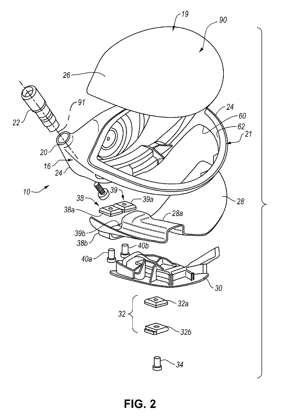
繊維、例えば、コーティング繊維2500を織る際、繊維は、複数の繊維を含むトウ(例えば、1K又は3Kトウ)に配置されてもよく、トウは、本明細書で検討された織りパターンに織られてもよい。繊維トウは、位置合せ機構、ロゴ、ブランド名、製品名、及び美的パターンが挙げられるが、これらに限定されない、ゴルフクラブの所望の視覚的特徴を生成するパターンに織られてもよい。いくつかの実施形態では、異なる色を有する着色コーティング繊維から構成されたトウは、所望の視覚的特徴を生成するために利用され得る。いくつかの実施形態では、非コーティング繊維のトウ及び着色コーティング繊維のトウは、所望の視覚的特徴を生成するために利用され得る。
When weaving the fibers, eg, the
いくつかの実施形態では、上述されたように、織物複合層(例えば、織物複合層2220及び2320)の金属繊維は、織物複合層の音響特性、及びそれ故に、ゴルフクラブヘッドなどのゴルフクラブの構成要素の音響特性に影響を及ぼす場合がある。このような実施形態では、金属繊維は、金属繊維トウであってもよい。金属繊維トウは、金属繊維から全体的に構成されるトウ又は金属繊維から部分的に構成されるトウであり得る。いくつかの実施形態では、金属繊維は、金属材料によりコーティングされた非金属コアを含んでもよい。このような実施形態では、コア繊維上の金属コーティングの厚さは、織物複合層についての音響特性に影響を及ぼす場合がある。一般的には、金属コーティングの厚さが大きいほど、織物複合層の減衰比は、金属材料により類似することとなる。したがって、十分に厚い(着色されていてもよい)金属コーティング層を有するコーティング非金属繊維は、織物複合層の音響特性に影響を及ぼす場合がある。いくつかの実施形態では、金属繊維は、個々の金属繊維であり得る。いくつかの実施形態では、金属繊維は、金属テープであり得る。いくつかの実施形態では、金属繊維は、コア繊維(フィラメント)の周囲に巻かれた金属テープであり得る。本明細書で使用するとき、「金属テープ」は、その幅より実質的に大きい長さを有し、その長さに対して垂直な断面領域がその高さより少なくとも1.5倍大きい幅を有する金属材料を意味する。いくつかの実施形態では、金属テープは、(着色されていてもよい)金属コーティングによりコーティングされたテープであり得る。
In some embodiments, as described above, the metal fibers of the woven composite layer (eg, woven
いくつかの実施形態では、金属コーティングの厚さの制御は、炭素鋼、ステンレス鋼(例えば、17−4PHステンレス鋼)、合金鋼、ニッケル系合金鉄、鋳鉄、アルミニウム合金、マグネシウム合金、銅合金、チタン合金、及びタングステン合金に正規化された、2〜10、2〜20、2〜50、2〜100、2〜200、3〜10、3〜20、3〜50、3〜100、3〜200、10〜20、10〜50、10〜100、又は10〜200の範囲の減衰比を達成するために選択されてもよい。 In some embodiments, controlling the thickness of the metal coating comprises carbon steel, stainless steel (eg, 17-4PH stainless steel), alloy steel, nickel-based ferroalloys, cast iron, aluminum alloys, magnesium alloys, copper alloys, Normalized to titanium alloy and tungsten alloy, 2 to 10, 2 to 20, 2 to 50, 2 to 100, 2 to 200, 3 to 10, 3 to 20, 3 to 50, 3 to 100, 3 to It may be selected to achieve a damping ratio in the range of 200, 10-20, 10-50, 10-100, or 10-200.
いくつかの実施形態では、織物複合層の音響特性に影響を与えるのに利用される金属コーティング層の厚さは、1.0マイクロメートル〜10マイクロメートルの範囲(部分範囲を含む)にあり得る。例えば、このような金属コーティング層の厚さは、1.0マイクロメートル、2.0マイクロメートル、3.0マイクロメートル、4.0マイクロメートル、5.0マイクロメートル、6.0マイクロメートル、7.0マイクロメートル、8.0マイクロメートル、9.0マイクロメートル、若しくは10マイクロメートル又はこれらの値の任意の2つを終点として含む範囲であり得る。 In some embodiments, the thickness of the metal coating layer utilized to affect the acoustic properties of the textile composite layer can be in the range of 1.0 micrometers to 10 micrometers (including subranges). . For example, the thickness of such a metal coating layer may be 1.0 micrometer, 2.0 micrometer, 3.0 micrometer, 4.0 micrometer, 5.0 micrometer, 6.0 micrometer, 7 micrometer. It may be 0.0 micrometers, 8.0 micrometers, 9.0 micrometers, or 10 micrometers or a range that includes any two of these values as endpoints.
いくつかの実施形態では、全体又は一部が金属繊維から構成されるトウは、織物複合層の音響特性に影響を及ぼすために利用され得る。いくつかの実施形態では、これらのトウは、織物複合層のベース繊維のトウと織り交ぜられてもよい。いくつかの実施形態では、ベース繊維のトウは、非金属繊維のトウであってもよい。いくつかの実施形態では、ベース繊維のトウは、(着色されていてもよいし又は着色されていなくてもよい)金属コーティング層によりコーティングされた非金属コアを含む繊維トウであり得る。非限定的な例として、織物複合層は、着色コーティング炭素繊維と、着色コーティング炭素繊維と織り交ぜられた金属繊維とを含んでもよい。 In some embodiments, tows composed entirely or partially of metal fibers can be utilized to affect the acoustic properties of the woven composite layer. In some embodiments, these tows may be interwoven with the base fiber tows of the woven composite layer. In some embodiments, the base fiber tow may be a non-metallic fiber tow. In some embodiments, the base fiber tow may be a fiber tow comprising a non-metallic core coated with a metal coating layer (which may or may not be colored). As a non-limiting example, the textile composite layer may include colored coated carbon fibers and metal fibers interwoven with the colored coated carbon fibers.
図27Aに、いくつかの実施形態による、ベース繊維トウ2712と織り交ぜられた金属繊維トウ2710を含む平織りパターン2700を図示する。金属繊維トウ2710は、全体又は一部が金属繊維から構成されるトウである。例えば、金属繊維トウ2710は、全体又は一部が金属繊維から構成される1K又は3K繊維トウであり得る。ベース繊維トウ2712は、ベース繊維から構成されるトウである。例えば、ベース繊維トウ2712は、ベース繊維から構成される1K又は3K繊維トウであり得る。いくつかの実施形態では、ベース繊維トウ2712と織り交ぜられた金属繊維トウ2710は、全体が1つ以上の金属材料で製造された繊維から構成される繊維トウであり得る。いくつかの実施形態では、金属繊維トウ2710の金属繊維は、非着色金属繊維であり得る。いくつかの実施形態では、金属繊維トウ2710の金属繊維は、金属材料内にコーティングされた非金属繊維コアを含んでもよい。いくつかの実施形態では、金属繊維トウ2710の金属繊維は、金属材料によりコーティングされた金属繊維コアを含んでもよい。いくつかの実施形態では、金属繊維トウ2710の金属繊維は、非金属コーティング、例えば、ポリマーコーティングでコーティングされた金属繊維コアを含んでもよい。
FIG. 27A illustrates a
織り交ぜられた金属繊維トウ2710を含む実施形態では、金属繊維トウ2710は、織物繊維複合層における繊維の総重量の、5wt%〜95wt%の範囲(部分範囲を含む)の重量%で存在してもよい。例えば、金属繊維トウ2710は、5wt%、10wt%、15wt%、20wt%、25wt%、30wt%、35wt%、40wt%、45wt%、50wt%、55wt%、60wt%、65wt%、70wt%、75wt%、80wt%、85wt%、90wt%、若しくは95wt%又はこれらの値の任意の2つを終点として有する範囲の重量%で存在してもよい。金属繊維トウ2710のwt%は、織物複合層に対して所望の減衰比及び音響特性を達成するために選択され得る。いくつかの実施形態では、金属繊維トウの重量%は、2500Hz超、3000Hz超、又は3300Hz超の自然周波数を有するように、インパクトによるゴルフクラブヘッドの音響周波数を大きくするために利用され得る。一般的には、金属繊維トウの重量%が大きいほど、織物複合層の減衰比は、金属材料により類似するであろう。
In embodiments that include interwoven
いくつかの実施形態では、金属繊維トウ2710の金属繊維の直径は、5マイクロメートル〜15マイクロメートルの範囲であり得る。いくつかの実施形態では、金属繊維トウ2710の金属繊維の直径は、5マイクロメートル〜10マイクロメートルの範囲であり得る。金属繊維トウ2710の金属繊維の直径は、織物複合層に対して所望の減衰割当量及び音響特性を達成するために選択され得る。いくつかの実施形態では、金属繊維の直径及び/又は(複数の)材料は、2500Hz超、3000Hz超、又は3300Hz超の自然周波数を有するように、インパクトによるゴルフクラブヘッドの音響周波数を大きくするために利用され得る。
In some embodiments, the diameter of the metal fibers of the
図27Aの平織りパターン2700は、金属繊維トウの織りパターンへの組込みを例示するために使用されているが、金属繊維トウは、任意の織りパターン、例えば、本明細書で検討された織りパターンに、織りパターン2700に関して検討されたような類似する様式で組み込まれてもよい。
Although the
いくつかの実施形態では、織物複合層(例えば、層2220又は2320)は、部分的に着色された織物複合層でもよい。このような実施形態では、織物複合層の1つ以上の部分が、着色織りパターンにより画定されてもよく、織物複合層の1つ以上の部分が、非着色織りパターンにより画定されてもよい。この説明の目的で、着色織りパターンは、少なくとも1つのセットの着色織布繊維/繊維トウを含む織りパターンである。着色織りパターンは、100%着色された繊維/繊維トウを含むことを必要としない。例えば、着色織りパターンは、非着色セットの繊維/繊維トウと織り交ぜられた着色セットの繊維/繊維トウを含んでもよい。例えば、図27Aにおける垂直配向繊維トウ2710は非着色でもよく、図27Aにおける水平配向繊維トウ2710は着色されていてよく、あるいはその逆でもよい。
In some embodiments, the textile composite layer (eg,
図53及び図54A〜図54Dに、織物複合層5311の上面5312の一部を画定する着色部分5320と、織物複合層5311の上面5312の一部を画定する非着色部分5330とを有する織物複合層5311を有するクラウンインサート5310を有するゴルフクラブヘッド5300を示す。例示の目的で、図54A〜図54Dの断面図に、クラウンインサート5310の織物複合層5311のみを示す。ただし、クラウンインサート5310は、本明細書で記載されたような他の層を含んでもよい。更に、図53及び図54A〜図54Dに、着色及び非着色部分を有するクラウンインサートを示す。本明細書で検討された他のゴルフクラブの構成要素(例えば、ソールインサート及びフェースインサート)は、図53及び図54A〜図54Dを参照して記載された着色及び非着色部分を含んでもよい。
53 and FIGS. 54A-54D, a fabric composite having a
着色部分5320は、図53において矩形ストリップとして図示されている。ただし、着色部分5320は、任意の所望の形状及びサイズを有し得る。更に、図53には、単一の着色部分5320が示されているが、織物複合層5311は、任意の好適な数の着色部分5320を含んでもよい。いくつかの実施形態では、(複数の)着色部分5320は、織物複合層5311の上面5312の5%以上、10%以上、20%以上、30%以上、40%以上、50%以上、60%以上、70%以上、80%以上、85%以上、90%以上、又は95%以上を画定し得る。いくつかの実施形態では、(複数の)着色部分5320は、織物複合層5311の上面5312の50%以下、例えば、織物複合層5311の上面5312の50%、40%、30%、20%、10%、5%、若しくは1%又はこれらの値の任意の2つを終点として有する範囲で規定し得る。いくつかの実施形態では、(複数の)着色部分5320は、上面5312において、クラウンインサート5310の周縁部の少なくとも一部を画定し得る。いくつかの実施形態では、着色部分5320の織りパターン及び非着色部分5330の織りパターンは同じでもよい。いくつかの実施形態では、着色部分5320の織りパターン及び非着色部分5330の織りパターンは(例えば、織り種、織り密度、織り材料等の1つ以上において)異なってもよい。
The
いくつかの実施形態では、着色部分5320は、非着色部分5330と直接織り交ぜられてもよい。このような実施形態では、織物複合層5311は、着色繊維/繊維トウを使用して着色部分5320を織り、非着色繊維/繊維トウを使用して非着色部分5330を織るように織られている。このような実施形態では、着色部分5320及び非着色部分5330は、部分5320と部分5330との間の画定された縁部を有さない単一の織物複合層を画定する。図54Aは、非着色部分5330と直接織り交ぜられた着色部分5320を有する織物複合層5311の断面図である。いくつかの実施形態では、上面5312及び5314は、図54Aにおける着色部分5320及び非着色部分5330により画定された平滑でシームレスな表面であり得る。
In some embodiments, the
いくつかの実施形態では、着色部分5320は、非着色部分5330を画定する1つ以上の非着色織物層に結合している別々の織物層でもよい。このような実施形態では、織物複合層5311は、プリプレグ着色織物層とプリプレグ非着色織物層とを積層し、プリプレグ層を共に結合することにより製造されてもよい。
In some embodiments, the
いくつかの実施形態では、プリプレグ着色層は、1つ以上の非着色織物層に隣接して積層される。図54Bに、非着色部分5330を画定する非着色織物層に隣接して配設された着色部分5320を画定する着色織物層を含む、織物複合層5311の断面図を示す。このような実施形態では、着色部分5320の縁部5322は、非着色部分5330の縁部5332に結合していてもよい。いくつかの実施形態では、上面5312及び5314は、図54Bにおける着色部分5320及び非着色部分5330により画定される平滑面であり得る。
In some embodiments, the prepreg color layer is laminated adjacent to one or more non-color fabric layers. FIG. 54B shows a cross-sectional view of a
図54Cに、非着色部分5330を画定する非着色織物層の上部に配設された着色部分5320を画定する着色織物層を含めた、織物複合層5311の断面図を示す。いくつかの実施形態では、図54Cに示されたように、着色部分5320の縁部5322は、着色部分5320と非着色部分5330との結合中に(例えば、成型/形成プロセス中に)非着色部分5330内に押し込まれてもよい。このような実施形態では、上面5312は、着色部分5320及び非着色部分5330により画定される平滑面であり得る。また、下面5314は、着色部分5320に対応する位置に突出部を有してもよい。いくつかの実施形態では、着色部分5320は、上面5312に突出部を画定し、下面5314が平滑であり得る(すなわち、図54Cの反対)ように非着色部分5330の上部に位置してもよい。図54Cの実施形態では、クラウンインサート5310を成形するために使用される成形型キャビティは、対向する平滑面を形成するために、下面5314又は上面5312上の突出部に対応する凹部を含んでもよい。
FIG. 54C shows a cross-sectional view of the
図54Dに、非着色部分5330を画定する非着色織物層の上部に配設され、非着色織物層と重なる着色部分5320を画定する着色織物層を含む、織物複合層5311の断面図を示す。いくつかの実施形態では、図54Dに示されたように、着色部分5320の縁部5322は、着色部分5320と非着色部分5330との結合中に(例えば、成型/形成プロセス中に)非着色部分5330内に押し込まれてもよい。このような実施形態では、上面5312は、着色部分5320及び非着色部分5330により画定された平滑面であり得る。また、下面5314は、不織部分5330の縁部5332により画定された突出部を含んでもよい。図54Dの実施形態では、クラウンインサート5310を成形するために使用される成形型キャビティは、平滑な上面5312を形成するために、図54Dの下面5314の形状に対応する表面を含んでもよい。このような実施形態では、上面5312は、上面5312と接触する成形型キャビティの形状をとってもよい。また、成形型の下面を外すことにより、樹脂の不要なはみ出しを防止することができ、これにより、成形されたインサートが着色部分と非着色部分との間で重なった位置で乾燥することを防止することができる。すなわち、このような成形型キャビティは、成形中にインサートにわたる等しい圧力を維持することにより、成形されたインサートにわたる樹脂及び繊維の比を容易に一貫させ/所望どおりにすることができる。
FIG. 54D shows a cross-sectional view of a
いくつかの実施形態では、本明細書に記載されているゴルフクラブヘッドは、ロフト角、ライ角、若しくはフェース角を互いに組み合わせて又は互いとは無関係にのいずれかで、調節することが可能な、1つ又は2つ以上の調節可能なロフト角、ライ角、又はフェース角システムを含んでもよい。例えば、ホーゼルインサート22の一部及びゴルフクラブシャフト(例えば、クラブシャフト102)は、組み立てられたゴルフクラブのホーゼル軸91(例えば、図2を参照のこと)を集合的に画定する。ホーゼルインサート22の一部は、クラブシャフトをアセンブリの長手方向軸線に沿って支持するために効果的であり得、同長手方向軸線は、オフセット角だけ、ホーゼル軸91からオフセットされている。ホーゼルインサート22は、0.25度の増分で0度〜4度であり得る、単一のオフセット角を提供し得る。例えば、オフセット角は、1.0度、1.25度、1.5度、1.75度、2.0度、2.25度、2.5度、2.75度、又は3.0度であり得る。いくつかの実施形態では、ホーゼルインサート22は、ホーゼル部分20及び/又はクラブシャフト102に取り外し可能に結合され得る。いくつかの実施形態では、ホーゼルインサート22は、ゴルフクラブヘッド10のロフト角、ライ角、又はフェース角を調節するように配置されることが可能であってよい。いくつかの実施形態では、ホーゼルインサート22は、全体が参照により本明細書に援用されている、2012年11月6日に特許を受けた米国特許第8,303,431号に記載されている、ロフト角、ライ角、又はフェース角のうちの少なくとも1つの調節を可能にするように構成され得る。
In some embodiments, the golf club heads described herein can adjust the loft, lie, or face angles either in combination with each other or independently of each other. One or more adjustable loft, lie, or face angle systems may be included. For example, a portion of
いくつかの実施形態では、ゴルフクラブヘッド10は、ゴルフクラブヘッド10の本体11のソール部分17に位置する後部ウェイトトラック30(又は後方ウェイトトラック30又は前後部ウェイトトラック30)を含んでもよい。後部ウェイトトラック30は、ウェイト32(又はウェイトアセンブリ32)が摺動可能に搭載されるトラックを画定する。いくつかの実装では、ウェイト32は、後部ウェイトトラック30に締結手段、例えば、ねじ34により摺動可能に搭載される。いくつかの実装では、ウェイト32は、マルチピース設計を有する。例えば、ウェイト32は、ウェイト32を形成するために共に結合している第1及び第2のウェイト構成要素32a、32bを有してもよい。いくつかの実装では、ウェイト32は、締結手段が張力下、すなわち、張力系に置かれるように、トラックの一部、例えば、少なくとも1つのレッジをクランプすることにより後部ウェイトトラック30に固定され得る。付加的に又は代替的に、ウェイト32は、締結手段が圧縮下、すなわち、圧力系に置かれるように、トラックの一部に対して圧縮することにより後部ウェイトトラック30に固定され得る。ただし、ウェイト32は、例えば、シングルピース設計などの図示以外の形態をとることができ、図示された以外の方法で後部ウェイトトラック30に移動可能に搭載されることができる。後部ウェイトトラック30により、ウェイト32が、ウェイトトラックに沿って前方及び後方に摺動可能な調節のために選択的に緩められ、締められることが可能となり、前方−後方方向におけるゴルフクラブヘッド10の有効な重心(CG)を調節することができる。ゴルフクラブヘッド10のCGを前方又は後方に調節することにより、ゴルフクラブヘッド10のパフォーマンス特性が調節される。同調節により、ゴルフクラブヘッド10により打たれたゴルフボールの飛行特性、例えば、ゴルフボールのトップスピン及びバックスピン特性に対する調節が促進される。
In some embodiments,
以下でより詳細に検討されるように、後部ウェイトトラック30は、ユーザに更なる調節性を提供する。打面のより近くにウェイトを移動させることにより、より低く、より前方のCGとなることに起因して、より低いスピンボールを生じ得る。これにより、ユーザは、一般的には、より高いロフトのクラブは、打つのが「より容易」になると考えられる、クラブヘッドのロフトを上げることも可能であると考えられる。クラブの後方に向かって後方にウェイトを移動させることにより、慣性モーメント(MOI)を大きくし、より高いスピンボールが可能となる。より高いMOIを有するクラブは、一般的には、打つのが「より容易」であると考えられる。したがって、後部ウェイトトラック30により、スピン及びMOI調節の少なくとも両方が可能となる。
As discussed in more detail below, the
示されたように、後部ウェイトトラック30は、後部ウェイトトラック30に沿う様々な位置、例えば、前方又は後方のいずれかにおいて、少なくとも1つのウェイトアセンブリを含んでもよい。2つ以上のウェイトが様々な位置の任意の一ヵ所に使用されてもよく、かつ/又は、クラブヘッド本体に戦略的に配置された複数のウェイトポートが存在してもよい。例えば、ゴルフクラブヘッド10は、トウウェイトポート及びヒールウェイトポートを含んでもよい。その後、ユーザは、ドロー又はフェードバイアスのいずれか一方を促進するために、トウ又はヒールのいずれか一方に、より多くのウェイトを移動させることができると考えられる。加えて、前方位置と後方位置との間で任意のウェイトを分割することにより、より高いMOIクラブとなる一方、すべてのウェイトをクラブの前方部分に移動させることにより、低い前方CGを有するゴルフクラブとなる。したがって、ユーザは、「寛大」でより高いMOIクラブ又はより低いスピンボールを生じさせるクラブの間で選択することができると考えられる。
As shown, the
例えば、図3を参照して、本体11のフレーム24は、前方領域12において、本体11のソール部分17に沿って、フレーム24と一体的に形成された前方又は側方ウェイトトラック36(又は前方若しくは側方チャネル36)を含んでもよい。側方ウェイトトラック36は、ゴルフクラブヘッド10のフェース部分42に対して概ね平行に延在するが、フェース部分42からオフセットされ、ウェイトトラック30に対して概ね垂直である。側方ウェイトトラック36は、少なくとも1つのウェイトが摺動可能に搭載され得るトラック又はポートを画定する。一例において、図2に示されたように、ウェイトは、2つのピース38a、38bを有する第1のウェイト38(又はウェイトアセンブリ38)と、2つのピース39a、39bを有する第2のウェイト39(又はウェイトアセンブリ39)とを含む。第1及び第2のウェイト38、39はそれぞれ、締結手段、例えば、各ねじ40a、40bにより、側方ウェイトトラック36に締結されている。いくつかの実装では、第1及び第2のウェイト38、39は、後部ウェイトトラック30に、締結手段が張力下に置かれる、すなわち、張力系であるように、このトラックの一部、例えば、少なくとも1つのリッジをクランプすることにより固定され得る。付加的に又は代替的に、第1及び第2のウェイト38、39は、後部ウェイトトラック30に、締結手段が圧力下に置かれる、すなわち、圧力系であるように、このトラックの一部に対して圧力を加えることにより固定され得る。第1及び第2のウェイト38、39は、示された以外の他の形状をとることができ、他の方法で搭載されることができ、シングルピースデザイン又はマルチピースデザイン(例えば、3つ以上のピース)をとることができる。
For example, with reference to FIG. 3, the
別の例によれば、例えば、図1及び図3に示されたように、1つのウェイト41(又はウェイトアセンブリ41)のみが、側方ウェイトトラック36に摺動可能に搭載されてもよい。ウェイト41は、1つのウェイト構成要素のみ、2つのウェイト構成要素(例えば、ねじ40cにより互いに締結された2つの積層ウェイト構成要素41a、41b)、又は3つ以上のウェイト構成要素を含んでもよい。
According to another example, only one weight 41 (or weight assembly 41) may be slidably mounted on the
側方ウェイトトラック36により、1つ以上のウェイトがヒール−トウ方向におけるゴルフクラブヘッド10の有効なCGを調節するため、ヒール−トウ方向において側方に摺動可能な調節のために選択的に緩められ、締められることが可能となる。ゴルフクラブヘッド10のCGを側方に調節することにより、ゴルフクラブヘッド10のパフォーマンス特性が調節される。同調節により、ゴルフクラブヘッド10により打たれたゴルフボールの飛行特性、例えば、ゴルフボールのサイドスピン特性に対する調節が促進される。特に、互いに独立して調節可能な2つのウェイト(例えば、第1及び第2のウェイト38、39)の使用により、ウェイト間の調節及び相互作用が可能となる。例えば、両ウェイトは、トウ領域14に完全に、ヒール領域16に完全に、互いに最長距離で離れて、一方のウェイトがトウ領域14に完全に、他方のウェイトがヒール領域16に完全に位置し、両方が側方ウェイトトラック36の中心若しくは中間位置に又は他のウェイト位置パターンに位置し得る。付加的に又は代替的に、第1及び第2のウェイト38、39は、後部ウェイトトラック30に位置する2つ以上のウェイトが存在するように、後部ウェイトトラック30に固定され得る。付加的に又は代替的に、第1及び第2のウェイト38、39はそれぞれ、ウェイト32と互換的であってもよい。
The
いくつかの実施形態では、側方ウェイトトラック又は前方チャネル36は、フェース部分42から、約5mm〜約50mm、例えば、約5mm〜約35mm、例えば、約5mm〜約30mm、例えば、約5mm〜約20mm、又は例えば、約5mm〜約15mmの、前方チャネルオフセット距離(同距離は、フェース部分42の打面43の中心を通過する第1の垂直面と打面43の中心と同じx軸座標における前方チャネル36との間の最短距離である)によりオフセットされる。同様に、後方トラック30は、フェース部分42から、約5mm〜約50mm、例えば、約5mm〜約40mm、例えば、約5mm〜約30mm、又は例えば、約10mm〜約30mmの、後方トラックオフセット距離(同距離は、打面43の中心を通過する第1の垂直面と打面43の中心と同じx軸座標における後方トラック30との間の最短距離である)によりオフセットされる。
In some embodiments, the side weight tracks or
特定の実施形態では、前方チャネル36及び後方トラック30は両方とも、特定のチャネル/トラック幅を有する。チャネル/トラック幅は、第1のチャネル壁と第2のチャネル壁との間の水平距離として測定され得る。前方チャネル36及び後方トラック30の両方について、これらの幅は、約5mm〜約20mm、例えば、約10mm〜約18mm、又は例えば、約12mm〜約16mmであり得る。いくつかの実施形態によれば、チャネル又はトラックの深さ(すなわち、底部チャネル壁とチャネルの前及び後縁部に隣接するソールの領域を含む仮想面との間の垂直距離)は、約6mm〜約20mm、例えば、約8mm〜約18mm、又は例えば、約10mm〜約16mmであり得る。
In certain embodiments, both
加えて、前方チャネル36及び後方トラック30は両方とも、特定のチャネル/トラック長を有する。チャネル/トラック長は、第3のチャネル壁と第4のチャネル壁との間の水平距離として測定され得る。前方チャネル36及び後方トラック30の両方について、それらの長さは、約30mm〜約120mm、例えば、約50mm〜約100mm、又は例えば、約60mm〜約90mmであり得る。付加的に又は代替的に、前方チャネル36の長さは、打面長の割合として表わされてもよい。例えば、前方チャネル36は、打面長の約30%〜約100%、例えば、打面長の約50%〜約90%又は例えば、約60%〜約80%であり得る。
In addition, both the
いくつかの例では、前方チャネル36は、摺動性ウェイトを保持してもよく、又は、フェースにわたる反発係数(COR)を改善及び/又は向上させる機構であってもよい。COR機構に関して、チャネルは、以下でより詳細に記載されるであろうように、様々な形態、例えば、チャネル又はスルースロットをとり得る。
In some examples, the
本明細書で開示されたゴルフクラブヘッドはそれぞれ、クラブヘッド本体の容積測定置換に等しい容積を有し得る。すなわち、1つ以上のウェイトポートをヘッド内に有するゴルフクラブヘッドについて、ウェイトポートは、存在しないか、又は、規則正しい仮想面により「覆われる」かのいずれかであると推定される。これにより、クラブヘッド容積は、ポートの存在又は不存在により影響を受けない。本願のゴルフクラブヘッドは、約110cm3〜約600cm3のヘッド容積を有するように構成され得る。より特定の実施形態では、ヘッド容積は、約250cm3〜約500cm3であり得る。更により具体的な実施形態では、ヘッド容積は、約300cm3〜約500cm3、約300cm3〜約360cm3、約300cm3〜約420cm3、又は約420cm3〜約500cm3であり得る。 Each of the golf club heads disclosed herein may have a volume equal to the volumetric displacement of the club head body. That is, for a golf club head having one or more weight ports in the head, the weight ports are presumed to be either absent or "covered" by a regular virtual surface. Thus, the club head volume is not affected by the presence or absence of the port. The golf club head of the present application, may be configured to have a head volume of about 110 cm 3 ~ about 600 cm 3. In a more specific embodiment, the head volume may be about 250 cm 3 ~ about 500 cm 3. In an even more specific embodiment, the head volume is about 300 cm 3 ~ about 500 cm 3, from about 300 cm 3 ~ about 360 cm 3, may be about 300 cm 3 ~ about 420 cm 3, or from about 420 cm 3 ~ about 500 cm 3.
ドライバーの場合には、ゴルフクラブヘッドは、約300cm3〜約460cm3の容積と、約145g〜約245gの総重量とを有してもよい。ウェアフェイウッドの場合には、ゴルフクラブヘッドは、約100cm3〜約250cm3の容積と、約145g〜約260gの総重量とを有してもよい。ユーティリティ又はハイブリッドクラブの場合には、ゴルフクラブヘッド10は、約60cm3〜約150cm3の容積と、約145g〜約280gの総重量を有してもよい。
In the case of a driver, golf club head includes a volume of about 300cm 3 ~ about 460cm 3, may have a total weight of about 145g~ about 245g. In the case of hardware Faye Wood, golf club head includes a volume of about 100cm 3 ~ about 250cm 3, may have a total weight of about 145g~ about 260g. In the case of utility or hybrid clubs,
一実施形態によれば、ソールインサート28より多くの三次元機構を有するより複雑な形状を有し得るウェイトトラック30は、後部ウェイトトラック30が後部ウェイトトラック30及びソールインサート28同士を結合するためにソールインサート28上に射出成型され、オーバーモールドされ、又はインサート成形され得るように、ソールインサート28と同じ、類似する、又は少なくとも適合可能な材料で製造され得る。一例において、クラウンインサート26、ソールインサート28、及び後部ウェイトトラック30は、互いに十分に結合可能な適合材料、例えば、共通のマトリクス若しくはベース又は少なくとも補完的なマトリクスを有するポリマー材料で製造される。例えば、クラウンインサート26及び/又はソールインサート28は、熱成形に十分適した連続繊維複合材料で製造されることができ、一方、ウェイトトラック30は、射出成型(インサート成形及びオーバーモールドを含む)に十分適した短い繊維複合材料(それぞれ共通のマトリクスを有する)で製造されることができる。射出成形に好適な材料の一例は、ポリウレタンスルフィド(PPS)ベース又はマトリクス中にショートチョップ繊維を有する熱可塑性炭素繊維複合材料である。例えば、後部ウェイトトラック30の材料は、PPSマトリクスを強化する、約1/10インチの長さを有する30体積%の短い炭素繊維を含んでもよい。後部ウェイトトラック30に使用され得る市販材料の別の例は、RTP Companyにより製造されるRTP1385UPである。他の例としては、ナイロン、RTP285、RTP4087UP、及びRTP1382UPが挙げられる。
According to one embodiment, the
一例において、ソールインサート28及び後部ウェイトトラック30同士は、ソールインサート28を成形型に置き、ソールインサート28上にトラック30を射出成形することにより結合される。射出成形プロセスにより、ソールインサート28と後部ウェイトトラック30との間に、その材料適合性による強力な融合様結合が形成される。
In one example, the
ソールインサート28が熱硬化性材料を使用して形成され得る代替的な例で、ソールインサート28及び後部ウェイトトラック30は、適合性材料ではなく、処理しないままでは十分に結合しないであろう。したがって、射出成形、インサート成形、又はオーバーモールド工程の前に、ソールインサート28は、好ましくは、熱活性化接着剤、例えば、Akron Coating & Adhesive,Inc.により製造されるACA30−114等によりコーティングされ得る。ACA30−114は、エポキシ樹脂誘導体と非極性粘着剤から設計された粘着促進剤と共に飽和ポリウレタンを有する熱活性化水性接着剤である。他の種類の熱活性化接着剤も使用され得ることが理解されるであろう。コーティング工程後に、ついで、ソールインサート28が、成形型に置かれ、後部ウェイトトラック30の材料が、上記されたようにソールインサート28上にオーバーモールドされ(又は射出成形され)得る。射出成形工程中に、熱により、ソールインサート28上の接着剤コーティングが活性され、ソールインサート28と後部ウェイトトラック30との間の結合が促進される。
In an alternative example where
ソールインサート28及び後部ウェイトトラック30同士が接着され、クラウンインサート26が形成された後に、それらは、市販のゴルフクラブに期待される通常の圧力、付加、並びに摩耗及び引裂きに堪えるように採用された強力な一体化構造を形成する様式で、フレーム24に結合される。例えば、ソールインサート28及びクラウンインサート26はそれぞれ、フレーム24にエポキシ接着剤を使用して結合され得る。ここで、クラウンインサート26は、クラウン開口62に固定されかつクラウン開口62を覆い、ソールインサート28は、ソール開口60に固定されかつソール開口60を覆う。代替的な取付け方法としては、ボルト、リベット、スナップフィット、接着剤、及び他の公知の結合方法が挙げられ、又は、これらの任意の組み合わせが、クラウンインサート26及びソールインサート28をフレーム24と結合するために使用され得る。
After the
図4に、クラウンインサート26が取り外されたヘッドを示し、上部からのヘッドの中空内部の視野を提供する。加えて、図4に、後部ウェイトトラック30がどのようにして、内部リブ、支持体、及びソールインサート28上にオーバーモールドされた他の機構を含むのかを図示する。例えば、後部ウェイトトラック30は、ソールインサートの中心リッジ28aの上に巻いている様々な支持体、リッジ28aの上部に沿う前後支持リブ、及び中心リッジ28aから外向きに延在する側方リブを含んでもよい。オーバーモールドプロセスにより、ウェイトトラック並びに他の複雑な機構及びディテールを、ゴルフクラブヘッド10の設計に組み込むことが可能となることが分かる。例えば、ウェイトトラック30により提供される性能上の利益に加えて、図4に示された様々なリブ及び機構は、ゴルフクラブヘッド10のための構造的支持及び更なる剛性を提供することができ、ゴルフクラブヘッド10の音響特性も修飾し、更に微調整することができる。ボールを打った際にゴルフクラブヘッド10により発せられる音及び音階周波数は、ゴルファーの感覚的経験に非常に重要であり、ボールのインパクトが打面43上で生じる箇所(及びボールが十分に打たれるかどうかについての機能的なフィードバックを提供する。
FIG. 4 shows the head with the
図5に、後部ウェイトトラック30がオーバーモールドされる前の、その中心リブ又はリッジ28aを含むソールインサート28を示す。リッジ28aは、ソールインサート上の中心に位置してもよく、更なる構造支持をゴルフクラブヘッドのソールに提供するために、概ね前から後ろに延在している。リッジ28aは、前後ウェイトトラック30が固定されたその外側表面上に細長いウェイト凹部又はポートも提供する。ソールインサートは、射出成形工程中に射出成形溶融物のための流動経路を提供し、ソールインサート28とオーバーモールドされたウェイトトラック30との間の機械的なインターロックを形成することにより、ソールインサートユニットを形成するために、様々な位置に複数のスルーホール50を含んでもよい。
FIG. 5 shows the
図6に、ソールインサート28に結合したオーバーモールドされた後部ウェイトトラック30を有するソールインサート28をより詳細に示す。後部ウェイトトラック30が、ソールインサート28の両側(内部及び外部)の周囲を覆っていることが、(特に他の図面に関して)分かる。ソールインサート28の外側表面にオーバーモールドされたウェイト取付けチャネル48及び周縁リッジ(又はレール)46に加えて、後部ウェイトトラック30は、好ましくは、1つ以上のリブ及び他の機構もソールインサートの内部表面に含む。例えば、図6に、リッジ28aの対向端上に覆われた強化支持体30a、30b、リッジ28aの上部に沿って辿る平行な前後延在リブ30c、30d、リブ30c、30dを繋ぐクロスリブ30e、並びに様々な側方及び他のリブ30f、30g、30h、30i、30j、30k、30l、30m、30n、30o、30p、及び30qを示す。これらはすべて、ソールインサート28及びゴルフクラブヘッド10を強化するために、支持リブ及び支持体の強化ネットワーク又マトリクスを形成するように相互接続されている。いくつかの実施形態では、少なくとも1つのウェイト部材の後部ウェイトトラック30内での移動により、少なくとも1つのウェイト部材の調節範囲全体を通して、約0.5mm〜約2.0mm未満(例えば、約1.0mm)のゴルフクラブヘッドの重心のヘッドを原点とするz軸座標における変化が生じる。
FIG. 6 shows the
リブが射出成形されるため、それらは、ゴルフクラブヘッドの音響特性を調節し、微調整するために、広い各種の形状、サイズ、配向、及びソールインサート上での位置を有し得る。図6において、リブネットワークにより、側方及び長手方向の両方に剛性が加えられていることにより、ゴルフクラブヘッドに戦略的に配置された剛性が付与されていることが分かる。これに関して、いくつかのリブ、例えば、リブ30j、30k、30l、30m、30o、30p、及び30qは、フレーム24上に構造的な構成要素を嵌合することにより、ソールインサート28をフレーム24に取り付けるために位置合わせし、かつ、ソールインサート28ユニットとフレーム24との間の強力な機械的結合を提供するためのフォーク状端部を有する。
As the ribs are injection molded, they can have a wide variety of shapes, sizes, orientations, and locations on the sole insert to adjust and fine tune the acoustic properties of the golf club head. In FIG. 6, it can be seen that the rib network adds stiffness in both the lateral and longitudinal directions, thereby providing strategically placed stiffness to the golf club head. In this regard, some ribs, e.g.,
図7を参照して、フレーム24は、好ましくは、クラウンインサート26を固定するための、クラウン開口62周囲に延在する窪んだシート又はリッジ52aを含む。同様に、フレーム24は、ソールインサート28を受容するための、ソール開口60周囲にシート又はリッジ52bを含む。ウェイト32のウェイト構成要素32a、32bは、その各チャネルに据えられ、レール46により分離されて示されている。ウェイト構成要素32a、32bは、ねじ34を受容するように位置合わせされた孔を有して示されている(例えば、図1及び2を参照のこと)。ウェイト構成要素32aの孔は、ねじ34を緩めることにより、ウェイトトラック30内で前方及び後方に摺動運動可能なようにウェイト構成要素を分離する一方、ねじ34を締めることにより、ゴルフコースでのプレイ中での摺動運動を防止するように、ウェイトが共にレール46との係止係合状態になるようにねじ状であり得る。
Referring to FIG. 7, the
図8に示されたように、後部ウェイトトラック30及び(ウェイト構成要素32a、32bを有する)2ピースウェイト32は、ウェイトトラック36及び(ウェイト構成要素41a、41bを含む)2ピースウェイト41に類似する。
As shown in FIG. 8, the
上記で言及されたのと同様に、いくつかの実施形態では、チャネル又は摺動ウェイトトラックの幅(すなわち、第1のリッジ及び第2のリッジの位置に隣接する第1のチャネル壁と第2のチャネル壁との間の距離)は、約8mm〜約20mm、例えば、約10mm〜約18mm、又は例えば、約12mm〜約16mmであり得る。また、上記言及されたものに則して、特定の実施形態では、チャネルの深さ(すなわち、底部チャネル壁とチャネルのリッジに隣接するソールの領域を含む仮想面との間の垂直距離)は、約6mm〜約20mm、例えば、約8mm〜約18mm、又は例えば、約10mm〜約16mmであり得る。上記言及されたものに加えて、いくつかの実施形態によれば、チャネルの長さ(すなわち、チャネルの第1の端部とチャネルの第2の端部との間の水平距離)は、約30mm〜約120mm、例えば、約50mm〜約100mm、又は例えば、約60mm〜約90mmであり得る。 As mentioned above, in some embodiments, the width of the channel or sliding weight track (i.e., the first channel wall and the second channel adjacent to the first and second ridge locations). The distance between the channel wall and the channel wall can be about 8 mm to about 20 mm, for example, about 10 mm to about 18 mm, or for example, about 12 mm to about 16 mm. Also, in accordance with what has been mentioned above, in certain embodiments, the depth of the channel (ie, the vertical distance between the bottom channel wall and an imaginary plane that includes the area of the sole adjacent to the ridge of the channel) is , About 6 mm to about 20 mm, for example, about 8 mm to about 18 mm, or for example, about 10 mm to about 16 mm. In addition to those mentioned above, according to some embodiments, the length of the channel (ie, the horizontal distance between the first end of the channel and the second end of the channel) is about It can be 30 mm to about 120 mm, for example, about 50 mm to about 100 mm, or for example, about 60 mm to about 90 mm.
いくつかの実施形態によれば、ゴルフクラブヘッド(例えば、図1〜図8に示されたゴルフクラブヘッド10)の調節可能なウェイトシステムを使用するために、ユーザは、ツール(例えば、トルクレンチ)の係合端を使用して、ウェイトアセンブリの締結ボルトを緩めることとなる。締結ボルトが緩められと、ウェイトアセンブリは、ウェイトアセンブリをチャネルにおいて摺動させることによるか、又は、ウェイトアセンブリをクラブヘッド上の異なる位置に再位置付けすることによるかのいずれか一方により調節され得る。ウェイトアセンブリが所望の位置にあると、締結ボルトは、ウェイトアセンブリがクラブヘッドに固定されるまで締められ得る。摺動性ウェイトの場合には、ウェイト締結ボルトは、ウェイトトラック又はチャネルの前方リッジ及び/又は後方リッジ上でのウェイトシステムのワッシャーとマス部材との間のクランプ力がウェイトアセンブリを適所に保持するために十分になるまで締められ得る。いくつかの実施形態では、ゴルフクラブヘッドは、前方リッジ及び/又は後方リッジ上に位置する係止突起部と、ワッシャーとマス部材とにより提供される係止力を大きくするために協同するワッシャー上に位置する係止ノッチとを含んでもよい。他の実施形態では、ゴルフクラブヘッドは、前方リッジ及び/又は後方リッジ上に位置する位置合せ突起部と、ワッシャー上に位置する位置合せノッチとを含んでもよい。位置合せ突起部又はバンプは、外側ウェイト部材又はワッシャーにおけるノッチ又は凹部の幅より小さい幅を有するようにサイズ決めされ、これにより、外側ウェイト部材は、バンプの一方の上に置かれた際に、移動量が制限され得る。この様式では、突起部又はバンプは、ウェイトアセンブリの位置をチャネルに沿って位置合わせするために役立つが、有意な係止機能を行わないマーカー又は指標として機能する。代わりに、ウェイトアセンブリは、ボルトを締めることにより、チャネルに沿う選択された位置に係止され得る。
According to some embodiments, to use an adjustable weight system for a golf club head (e.g.,
示された実施形態では、ウェイトアセンブリは、3つの構成要素、すなわち、内側部材、外側部材、及び締結ボルトを含む。外側部材は、内部チャネルの体積の外側部分の中に位置し、リッジの外向きに面する表面と係合し得る。内側部材は、内部チャネルの体積の内側部分の中に位置し、リッジの内向きに面する表面と係合し得る。締結ボルトは、外側部材の中央開口を通って延在し、マス部材の中央開口に位置する噛合するねじと係合する、ねじ状シャフトを有する。これは、ウェイトアセンブリを固定するための張力系である。代替的に、ワッシャーは、中央開口に噛合するねじ山を有することができ、締結ボルトは、マス部材の中央開口を通って進み、ボルトの露出した外側表面でドライバーにより締結されることができると考えられる。この実施形態では、ボルトのヘッドは、締結中にヘッドを適所に保持しているマス部材の内側表面に捕捉されると考えられる。 In the illustrated embodiment, the weight assembly includes three components: an inner member, an outer member, and a fastening bolt. The outer member is located within the outer portion of the volume of the inner channel and may engage the outwardly facing surface of the ridge. The inner member is located within the inner portion of the volume of the inner channel and may engage the inwardly facing surface of the ridge. The fastening bolt has a threaded shaft extending through the central opening of the outer member and engaging a mating screw located at the central opening of the mass member. This is a tension system for fixing the weight assembly. Alternatively, the washer can have threads that engage the central opening, and the fastening bolt can be advanced through the central opening of the mass member and fastened by a screwdriver on the exposed outer surface of the bolt. Conceivable. In this embodiment, the head of the bolt would be trapped on the inner surface of the mass member holding the head in place during fastening.
いくつかの実施形態では、ワッシャーは、マス部材より重くてもよく、その逆でもよい。あるいは、ワッシャー及びマス部材は、類似する重量を有してもよい。マス部材より重いワッシャーを製造する利点は、更に低いCGである。ワッシャー及び/又はマス部材は、1g〜50gの範囲の重量を有し得る。 In some embodiments, the washer may be heavier than the mass member and vice versa. Alternatively, the washer and the mass member may have similar weights. The advantage of manufacturing a washer that is heavier than the mass member is lower CG. The washer and / or mass member may have a weight in the range of 1 g to 50 g.
本明細書における様々な実施形態に開示された複合ソール及びウェイトトラックは、チタン又は他の金属ウェイトトラックを有する従来のクラブヘッドに関連する製造上の課題を克服し、比較的重いウェイトトラックを軽量な複合材料により置き換える(ゴルフクラブヘッド内のどこかに戦略的に割り当てられ得る任意の重量を解放する)。例えば、更なるリブは、ゴルフクラブヘッドの中空内部に戦略的に加えられることにより、ヘッドの音響特性を改善し得る。リブは、ヘッド内部における選択位置を強化し、同位置に剛性を加えるために、戦略的に配置され得る。(摺動性ウェイト機構により任意の更なるCG調節が可能になるのとは別に)有効なCGを前後、トウ向き、若しくはヒール向き又は両方に移動させるために、リブ又は他の機構の形態における任意の重量もまた内部に戦略的に配置され得る。加えて、複合ソールインサート及びクラウンインサート28、26は、構造的支持及び剛性をゴルフクラブヘッド10に提供し、かつ、ゴルフクラブヘッド10のどこかに割り当てられ得る任意の重量を解放する。
The composite sole and weight tracks disclosed in various embodiments herein overcome the manufacturing challenges associated with conventional club heads having titanium or other metal weight tracks and reduce the weight of relatively heavy weight tracks. (To release any weight that could be strategically assigned anywhere within the golf club head). For example, additional ribs may be strategically added to the hollow interior of the golf club head to improve the acoustic properties of the head. Ribs can be strategically placed to enhance and add rigidity to selected locations within the head. In order to move the active CG back and forth, toe, or heel or both (apart from the sliding weight mechanism allowing any further CG adjustment), in the form of ribs or other mechanisms Any weight can also be strategically placed inside. In addition, the composite sole and crown inserts 28, 26 provide structural support and stiffness to the
いくつかの実施形態によれば、本開示のゴルフクラブヘッド10は、ゴルフクラブヘッド10の本体11のソール部分に位置する、少なくとも1つの反発係数(COR)機構を含む。ゴルフクラブヘッド10のCORは、ゴルフボールがゴルフクラブヘッド10により打たれた際の、ゴルフクラブヘッド10とゴルフボールとの間でのエネルギー損失又は保持の測定値である。望ましくは、ゴルフクラブヘッド10のCORは、ボールとのインパクト中に、ゴルフクラブヘッド10からボールへのエネルギーの効率的な移動を促進するために高くなる。したがって、ゴルフクラブヘッド10のCOR機構により、ゴルフクラブヘッド10のCORの増大が促進される。
According to some embodiments, the
ゴルフクラブヘッド10のいくつかの実装では、COR機構は、チャネル、スロット、又はゴルフクラブヘッド10のCORを増大させるように構成されているいくつかの他の部材のうちの1つ以上である。一般的には、例えば、チャネル又はスロットなどのCOR機構は、ゴルフクラブヘッド10の打面43の周辺柔軟性を増大又は向上させることによりゴルフクラブヘッド10のCORを増大させる。特定の実装によれば、CRO機構は、本体11のソール部分17の前方領域12において、ソール部分17の最前方縁部に隣接し又は同縁部の近くに位置してもよい。
In some implementations of
ゴルフクラブヘッド10のCOR機構のチャネルに関する更なる詳細は、その全体が参照により本明細書に組み込まれている、2011年12月27日、2012年5月10日、及び2013年3月14日にそれぞれ出願された米国特許出願第13/338,197号、同第13/469,031号、同第13/828,675号に見出すことができる。ゴルフクラブヘッド10のCOR機構のスロットに関する更なる詳細は、その全体が参照により本明細書に組み込まれている、2013年3月15日に出願された米国特許出願第13/839,727号に見出すことができる。ゴルフクラブヘッド10のCOR機構に関するより更なる詳細は、その全体が参照により本明細書に組み込まれている、2010年6月1日に出願された米国特許第8,235,844号、2011年12月13日に出願された同第8,241,143号、2011年12月14日に出願された同第8,241,144号に見出すことができる。
Additional details regarding the channels of the COR mechanism of
本開示のゴルフクラブヘッド10は、ゴルフクラブヘッド10のパフォーマンス特性を促進する他の機構を備えてもよい。例えば、ゴルフクラブヘッド10は、いくつかの実装では、米国特許第6,773,360号、同第7,166,040号、同第7,452,285号、同第7,628,707号、同第7,186,190号、同第7,591,738号、同第7,963,861号、同第7,621,823号、同第7,448,963号、同第7,568,985号、同第7,578,753号、同第7,717,804号、同第7,717,805号、同第7,530,904号、同第7,540,811号、同第7,407,447号、同第7,632,194号、同第7,846,041号、同第7,419,441号、同第7,713,142号、同第7,744,484号、同第7,223,180号、同第7,410,425号、及び同第7,410,426号においてより詳細に記載されている機構に類似する、移動可能なウェイト機構を含む。それぞれの文献の内容は、その全体が参照により本明細書に組み込まれている。
The
特定の実装では、例えば、ゴルフクラブヘッド10は、米国特許第7,775,905号及び同第8,444,505号、2013年5月20日に出願された米国特許出願第13/898,313号、2013年10月7日に出願された米国特許出願第14/047,880号、2012年9月18日に出願された米国特許出願第61/702,667号、2013年3月15日に出願された米国特許出願第13/841,325号、2013年7月19日に出願された米国特許出願第13/946,918号、2015年7月1日に出願された米国特許出願第14/789,838号、2014年7月3日に出願された米国特許出願第62/020,972号、2014年10月17日に出願された特許出願第62/065,552号、及び2015年3月31日に出願された特許出願第62/141,160号においてより詳細に記載された機構に類似する、摺動可能なウェイト機構を含む。それぞれの文献の内容は、その全体が参照により本明細書に組み込まれている。
In certain implementations, for example,
いくつかの実装によれば、ゴルフクラブヘッド10は、その全体の内容が参照により本明細書に組み込まれている米国特許出願公開第2013/0123040(A1)号においてより詳細に記載された機構に類似する、空気力学的形状機構を含む。
According to some implementations, the
更にいくつかの実装によれば、ゴルフクラブヘッド10は、その全体の内容が参照により本明細書に組み込まれている、米国特許第8,025,587号、同第8,235,831号、同第8,337,319号、米国特許出願公開第2011/0312437(A1)号、同第2012/0258818(A1)号、同第2012/0122601(A1)号、同第2012/0071264(A1)号、及び米国特許出願第13/686,677号においてより詳細に記載された機構に類似する、調節可能なロフト/ライ機構を含む。
According to some further implementations, the
加えて、いくつかの実装では、ゴルフクラブヘッド10は、その全体の内容が参照により本明細書に組み込まれている、米国特許第8,337,319号、米国特許出願公開第2011/0152000(A1)号、同第2011/0312437(A1)号、同第2012/0122601(A1)号、及び米国特許出願第13/686,677号においてより詳細に記載された機構に類似する、調節可能なソール機構を含む。
In addition, in some implementations, the
特定の実装によれば、ゴルフクラブヘッド10は、その全体が参照により本明細書に組み込まれている、米国特許出願第12/006,060号並びに米国特許第6,997,820号、同第6,800,038号、及び同第6,824,475号においてより詳細に記載された機構に類似する、可変厚さのフェース部分要素を含む。
According to certain implementations, the
いくつかの実装では、ゴルフクラブヘッド10は、その全体が参照により本明細書に組み込まれている、米国特許出願第11/998,435号、同第11/642,310号、同第11/825,138号、同第11/823,638号、同第12/004,386号、同第12/004,387号、同第11/960,609号、同第11/960,610号、及び米国特許第7,267,620号においてより詳細に記載された機構に類似する、複合フェース部分要素を含む。
In some implementations, the
一実施形態によれば、例えば、ゴルフクラブヘッド10などのゴルフクラブを製造する方法は、下記工程:(1)ソール開口を有するフレームを形成し、複合積層ソールインサートを形成し、熱可塑性複合ヘッド構成要素をソールインサートの上に射出成形して、ソールインサートユニットを生成し、ソールインサートをフレームに接合させる工程、(2)1つ以上の摺動性ウェイトを支持可能なウェイトトラックである複合ヘッド構成要素を提供する工程、(3)ソールインサートを、ウェイトラックと結合するために適合可能なマトリクスを有する熱可塑性複合材料から形成する工程、(4)ソールインサートを、ガラス繊維、アラミド繊維、炭素繊維、及びこれらの任意の組み合わせからなる群から選択され、ポリフェニレンスルフィド(PPS)、ポリアミド、ポリプロピレン、熱可塑性ポリウレタン、熱可塑性ポリウレア、ポリアミド−アミド(PAI)、ポリエーテルアミド(PEI)、ポリエーテルエーテルケトン(PEEK)、及びこれらの任意の組み合わせからなる熱可塑性マトリクスを有する、連続繊維を有する連続繊維複合材料から形成する工程、(5)ソールインサート及びウェイトトラックの両方を、適合性マトリクスを有する熱可塑性複合材料から形成する工程、(6)ソールインサートを、熱可塑性材料から形成し、ソールインサートを、熱活性化接着剤によりコーティングし、ウェイトトラックを、コーティング工程後のソールインサートの上に射出成形可能な熱可塑性材料から形成する工程、(7)フレームを、チタン、1つ以上のチタン合金、アルミニウム、1種以上のアルミニウム合金、鋼、1種以上の鋼合金、及びこれらの任意の組み合わせからなる群から選択される材料から形成する工程、(8)クラウン開口を有するフレームを形成し、クラウンインサートを、複合積層材料から形成し、クラウンインサートがクラウン開口を覆うように、クラウンインサートをフレームに接合させる工程、(9)複合ヘッド構成要素を、ヘッドを強化する1つ以上のリブ、ヘッドの音響特性を調整する1つ以上のリブ、ゴルフクラブヘッドのソール部分における固定ウェイトを受容する1つ以上のウェイトポート、摺動性ウェイトを受容する1つ以上のウェイトトラック、及びこれらの組み合わせからなる群から選択する工程、(10)ソールインサート及びクラウンインサートを、連続炭素繊維複合材料から形成する工程、(11)ソールインサート及びクラウンインサートを、熱硬化に好適な材料を使用する熱硬化により形成し、ソールインサートを熱活性化接着剤によりコーティングする工程、(12)フレームを、チタン、チタン合金、又はこれらの組み合わせから、クラウン開口を有するように形成し、ソールインサート及びウェイトトラックを、ポリフェニレンスルフィド(PPS)、ポリアミド、ポリプロピレン、熱可塑性ポリウレタン、熱可塑性ポリウレア、ポリアミド−アミド(PAI)、ポリエーテルアミド(PEI)、ポリエーテルエーテルケトン(PEEK)、及びこれらの任意の組み合わせからなる群から選択されるマトリクスを有する熱可塑性炭素繊維材料から形成する工程、並びに(13)クラウン開口を有するフレームを形成し、クラウンインサートを、熱可塑性複合材料から形成し、クラウンインサートがクラウン開口を覆うように、クラウンインサートをフレームに接合させる工程のうちの1つ以上を含む。
According to one embodiment, for example, a method of manufacturing a golf club such as
付加的に又は代替的に、本体11及び/又はフレーム24は、下記材料:炭素鋼、ステンレス鋼(例えば、17−4PHステンレス鋼)、合金鋼、Fe−Mn−Al合金、ニッケル系合金鉄、鋳鉄、超合金鋼、アルミニウム合金、マグネシウム合金、銅合金、チタン合金、又はこれらの混合物で製造され得る。ソールインサート、クラウンインサート、及び/又は摺動性ウェイトトラックは、例えば、約1g/cm3〜約2g/cm3などの約2g/cm3未満の密度を有する非金属材料で形成され得る。非金属材料は、好ましくは、ポリマー又はポリマー強化複合材から構成され得る。ポリマーは、熱硬化性又は熱可塑性のいずれか一方であることができ、非晶性、結晶性、及び/又は半結晶性構造であることができる。ポリマーは、例えば、結晶性若しくは半結晶性エンジニアリングプラスチック又は非晶性エンジニアリングプラスチックなどのエンジニアリングプラスチックで形成されてもよい。可能性のあるエンジニアリングプラスチックの候補としては、ポリフェニレンスルフィドエーテル(PPS),ポリエーテルイミド(PEI)、ポリカーボネート(PC)、ポリプロピレン(PP)、アクリロニトリル−ブタジエンスチレンプラスチック(ABS)、ポリオキシメチレンプラスチック(POM)、ナイロン6、ナイロン6−6、ナイロン12、ポリメチルメタクリレート(PMMA)、ポリフェニレンオキシド(PPO)、ポリブチレンテレフタレート(PBT)、ポリスルホン(PSU)、ポリエーテルスルホン(PES)、ポリエーテルエーテルケトン(PEEK)、又はこれらの混合物が挙げられる。それ以外にも、ソールインサート、クラウンインサート、及び/又は摺動性ウェイトトラックを形成する間に、例えば、ガラス繊維、炭素繊維、又は金属繊維などの有機短繊維が、ソールインサート、クラウンインサート、及び/又は摺動性ウェイトトラックの構造的強度を向上させるために、エンジニアリングプラスチックに加えられ得る。ただし、好ましくは、強化材は、短繊維ではなく、連続長繊維である。最も好ましい熱硬化性材料は、連続長繊維グラファイトエポキシ複合材であると考えられる。最も好ましい熱可塑性材料は、連続長繊維グラファイト強化材を有するPPS又はPSUポリマーのいずれか一方であると考えられる。エポキシ及びPSUの利点の1つは、両者が比較的低減衰でありながら比較的剛性であり、これにより、過減衰する場合がある他のポリマーと比較して、より良好な音又はより大きい金属音を生成する。加えて、PSUは、最終的に仕上がったゴルフクラブヘッドを達成するための仕上げ又は塗装を必要としない点で、後処理をほとんど必要としない。
Additionally or alternatively, the
いくつかの実施形態では、ゴルフクラブヘッドを製造する方法は、クラウンインサート又はソールインサートを形成することを含んでもよく、インサートの形成は、下記工程:(1)着色コーティング炭素繊維を形成するために炭素繊維をコーティングする工程、(2)複数のプリプレグ一方向性繊維複合プライを積層して、プリプレグ繊維複合層を形成する工程であって、複数のプリプレグ一方向性繊維複合プライが、最内側プリプレグ一方向性繊維複合プライ及び最外側プリプレグ一方向性繊維複合プライを含む、工程、(3)着色炭素繊維を含む織物複合層を形成する工程、(4)プリプレグ繊維複合層及び織物複合層を硬化させる工程、(5)織物複合層を、最外側プリプレグ一方向性繊維複合プライに直接又は間接的に接着させる工程、並びに(6)織物複合層の最外側表面を、光透過性コーティングによりコーティングする工程のうちの1つを含む。工程(1)において、炭素繊維は、電気メッキプロセス、CVDプロセス、PVDプロセス、又は陽極酸化プロセスを使用してコーティングされてもよい。いくつかの実施形態では、工程(2)において、最外側プリプレグ一方向性繊維複合プライは、着色コーティング炭素繊維を含んでもよい。いくつかの実施形態では、工程(5)において、プリプレグ繊維複合層及び織物複合層は共に硬化されて、織物複合層を、最外側プリプレグ一方向性繊維複合プライに直接接着させ得る。いくつかの実施形態では、ソールインサート及び/又はクラウンインサートは、熱形成を含むプロセスにより製造されてもよい。 In some embodiments, a method of manufacturing a golf club head may include forming a crown insert or a sole insert, wherein forming the insert includes the following steps: (1) forming colored coated carbon fibers. A step of coating a carbon fiber, and (2) a step of laminating a plurality of prepreg unidirectional fiber composite plies to form a prepreg fiber composite layer, wherein the plurality of prepreg unidirectional fiber composite plies are formed of an innermost prepreg. A step including a unidirectional fiber composite ply and an outermost prepreg a unidirectional fiber composite ply, (3) a step of forming a woven composite layer containing colored carbon fibers, and (4) curing of the prepreg fiber composite layer and the woven composite layer. (5) adhering the textile composite layer directly or indirectly to the outermost prepreg unidirectional fiber composite ply Extent, as well as the outermost surface of the (6) textile composite layer comprises one of the step of coating the light-transmitting coating. In step (1), the carbon fibers may be coated using an electroplating process, a CVD process, a PVD process, or an anodizing process. In some embodiments, in step (2), the outermost prepreg unidirectional fiber composite ply may include colored coated carbon fibers. In some embodiments, in step (5), the prepreg fiber composite layer and the fabric composite layer may be cured together to adhere the fabric composite layer directly to the outermost prepreg unidirectional fiber composite ply. In some embodiments, the sole insert and / or the crown insert may be manufactured by a process that includes thermoforming.
いくつかの実施形態では、炭素繊維をコーティングすることは、個々の繊維をコーティングすることを含んでもよい。いくつかの実施形態では、炭素繊維をコーティングすることは、炭素繊維の個々のトウをコーティングすることを含んでもよい。いくつかの実施形態では、炭素繊維をコーティングすることは、織物炭素繊維のシート及び/又は炭素繊維トウをコーティングすることを含んでもよい。 In some embodiments, coating the carbon fibers may include coating individual fibers. In some embodiments, coating the carbon fibers may include coating individual tows of the carbon fibers. In some embodiments, coating the carbon fiber may include coating a sheet of woven carbon fiber and / or carbon fiber tow.
いくつかの実施形態では、ゴルフクラブヘッドを製造する方法は、クラウンインサート又はソールインサートを形成することを含んでもよく、インサートの形成は、下記工程:(1)炭素繊維を織って、織りパターンを形成する工程、(2)複数のプリプレグ一方向性繊維複合プライを積層して、プリプレグ繊維複合層を形成する工程、(3)織りパターンを金属/着色コーティングする工程、(4)織物繊維パターンをマトリクス材料に埋め込む工程、(5)プリプレグ繊維複合層及び/又は織物複合層を硬化させる工程、(6)織物複合層を最外側プリプレグ一方向性繊維複合プライに直接又は間接的に接着させる工程、並びに(7)織物複合層の最外側表面を光透過性コーティングによりコーティングする工程のうちの1つ以上を含む。工程(3)において、コーティングすることは、電気メッキプロセス、CVDプロセス、PVDプロセス、又は陽極酸化プロセスを使用して適用されてもよい。いくつかの実施形態では、工程(2)において、最外側プリプレグ一方向性繊維複合プライは、着色コーティング炭素繊維を含んでもよい。いくつかの実施形態では、工程(5)において、プリプレグ繊維複合層及び織物複合層は共に硬化されて、織物複合層を、最外側プリプレグ一方向性繊維複合プライに直接接着させ得る。いくつかの実施形態では、ソールインサート及び/又はクラウンインサートは、熱形成を含むプロセスにより製造されてもよい。 In some embodiments, a method of manufacturing a golf club head may include forming a crown insert or a sole insert, wherein forming the insert includes the following steps: (1) weaving carbon fibers to form a weave pattern. Forming, (2) laminating a plurality of prepreg unidirectional fiber composite plies to form a prepreg fiber composite layer, (3) metal / color coating the woven pattern, and (4) woven fiber pattern. Embedding in a matrix material, (5) curing the prepreg fiber composite layer and / or the textile composite layer, (6) directly or indirectly bonding the textile composite layer to the outermost prepreg unidirectional fiber composite ply, And (7) coating the outermost surface of the textile composite layer with a light transmissive coating.In step (3), the coating may be applied using an electroplating process, a CVD process, a PVD process, or an anodizing process. In some embodiments, in step (2), the outermost prepreg unidirectional fiber composite ply may include colored coated carbon fibers. In some embodiments, in step (5), the prepreg fiber composite layer and the fabric composite layer may be cured together to adhere the fabric composite layer directly to the outermost prepreg unidirectional fiber composite ply. In some embodiments, the sole insert and / or the crown insert may be manufactured by a process that includes thermoforming.
いくつかの実施形態では、所望の形状の織物炭素繊維材料は、ゴルフクラブの構成要素に加工するために、織物シートから切断されてもよい。所望の形状が切断される織物シートは、硬化したマトリクス材料に埋め込まれた織物繊維材料のシートであり得る。 In some embodiments, a woven carbon fiber material of a desired shape may be cut from a woven sheet for processing into a golf club component. The textile sheet from which the desired shape is cut can be a sheet of textile fiber material embedded in a cured matrix material.
いくつかの実施形態では、ゴルフクラブの構成要素を製造する方法は、最小織り密度を有するあるパターンの炭素繊維(例えば、織物炭素繊維材料のシート)を織ることを含んでもよい。本明細書で検討された織りパターンのいずれかが、本明細書で検討された最小織り密度(例えば、織りパターン1平方メートル当たり50〜650グラム(g/m2)の範囲の最小織り密度)を有するように織られてもよい。いくつかの実施形態では、パターン状に織られた繊維は、着色/金属コーティング繊維でもよい。いくつかの実施形態では、パターン状に織られた繊維は、着色/金属コーティングされなくてもよい。いくつかの実施形態では、好適な織り密度を有する織物繊維パターンを織った後に、織物繊維パターンは、マトリクス材料に埋め込まれて、織布繊維複合材を形成し得る。炭素繊維及び/又は炭素繊維トウの織りパターンが着色/金属コーティングされている実施形態では、着色/金属コーティングは、織りパターンをマトリクス材料に埋め込む前に適用され得る。着色/金属コーティングは、織りパターンの上面及び/又は織りパターンの下面に適用されてもよい。
In some embodiments, a method of manufacturing a component of a golf club may include weaving a pattern of carbon fibers having a minimum weave density (eg, a sheet of woven carbon fiber material). Either weave pattern is discussed herein, the minimum weave density are discussed herein (e.g., the minimum weave density in the range of weave patterns per
本明細書に記載された実施形態について例示的なポリマーとしては、合成及び天然ゴム、熱硬化性ポリマー、例えば、熱硬化性ポリウレタン又は熱硬化性ポリウレア、並びに、熱可塑性エラストマーを含む熱可塑性ポリマー、例えば、熱可塑性ポリウレタン、熱可塑性ポリウレア、メタロセン触媒ポリマー、単峰性エチレン/カルボン酸コポリマー、単峰性エチレン/カルボン酸/カルボキシレートターポリマー、二峰性エチレン/カルボン酸コポリマー、二峰性エチレン/カルボン酸/カルボキシレートターポリマー、ポリアミド(PA)、ポリケトン(PK)、コポリアミド、ポリエステル、コポリエステル、ポリカーボネート、ポリフェニレンスルフィド(PPS)、環状オレフィンコポリマー(COC)、ポリオレフィン、ハロゲン化ポリオレフィン[例えば、塩素化ポリエチレン(CPE)]、ハロゲン化ポリアルキレン化合物、ポリアルケナマー、ポリフェニレンオキシド、ポリフェニレンスルフィド、ジアリルフタレートポリマー、ポリイミド、塩化ポリビニル、ポリアミド−アイオノマー、ポリウレタンアイオノマー、ポリビニルアルコール、ポリアリレート、ポリアクリレート、ポリフェニレンエーテル、耐衝撃性改質ポリフェニレンエーテル、ポリスチレン、高耐衝撃性ポリスチレン、アクリロニトリル−ブタジエン−スチレンコポリマー、スチレン−アクリロニトリル(SAN)、アクリロニトリル−スチレン−アクリロニトリル、スチレン−無水マレイン酸(S/MA)ポリマー、スチレン−ブタジエン−スチレン(SBS)、スチレン−エチレン−ブチレン−スチレン(SEBS)、及びスチレン−エチレン−プロピレン−スチレン(SEPS)を含むスチレンブロックコポリマー、スチレンターポリマー、ヒドロキシル化、官能化スチレンコポリマー及びターポリマーを含む官能化スチレンブロックコポリマー、セルロースポリマー、液晶ポリマー(LCP)、エチレン−プロピレン−ジエンターポリマー(EPDM)、エチレン−酢酸ビニルコポリマー(EVA)、エチレン−プロピレンコポリマー、プロピレンエラストマー(例えば、全内容が参照により本明細書に組み込まれている米国特許第6,525,157号(Kim et al)に記載されたもの)、エチレン酢酸ビニル、ポリウレア、及びポリシロキサン並びにこれらの任意及びすべての組み合わせを挙げることができるが、これらに限定されない。 Exemplary polymers for the embodiments described herein include synthetic and natural rubbers, thermoset polymers such as thermoset polyurethanes or thermoset polyureas, and thermoplastic polymers, including thermoplastic elastomers, For example, thermoplastic polyurethane, thermoplastic polyurea, metallocene catalyzed polymer, monomodal ethylene / carboxylic acid copolymer, monomodal ethylene / carboxylic acid / carboxylate terpolymer, bimodal ethylene / carboxylic acid copolymer, bimodal ethylene / Carboxylic acid / carboxylate terpolymer, polyamide (PA), polyketone (PK), copolyamide, polyester, copolyester, polycarbonate, polyphenylene sulfide (PPS), cyclic olefin copolymer (COC), polyolefin, halogen Polyolefin [eg, chlorinated polyethylene (CPE)], halogenated polyalkylene compound, polyalkenamer, polyphenylene oxide, polyphenylene sulfide, diallyl phthalate polymer, polyimide, polyvinyl chloride, polyamide-ionomer, polyurethane ionomer, polyvinyl alcohol, polyarylate, polyacrylate , Polyphenylene ether, impact modified polyphenylene ether, polystyrene, high impact polystyrene, acrylonitrile-butadiene-styrene copolymer, styrene-acrylonitrile (SAN), acrylonitrile-styrene-acrylonitrile, styrene-maleic anhydride (S / MA) Polymer, styrene-butadiene-styrene (SBS), styrene-ethylene-butyl -Styrene (SEBS) and styrene block copolymers including styrene-ethylene-propylene-styrene (SEPS), styrene terpolymers, hydroxylated, functionalized styrene block copolymers including functionalized styrene copolymers and terpolymers, cellulose polymers, liquid crystals Polymer (LCP), ethylene-propylene-diene terpolymer (EPDM), ethylene-vinyl acetate copolymer (EVA), ethylene-propylene copolymer, propylene elastomer (for example, U.S. Patents incorporated herein by reference in their entirety). No. 6,525,157 (Kim et al), ethylene vinyl acetate, polyureas, and polysiloxanes, and any and all combinations thereof. But it is not limited to these.
これらの中でも、ポリアミド(PA)、ポリフタルイミド(PPA)、ポリケトン(PK)、コポリアミド、ポリエステル、コポリエステル、ポリカーボネート、ポリフェニレンスルフィド(PPS)、環状オレフィンコポリマー(COC)、ポリフェニレンオキシド、ジアリルフタレートポリマー、ポリアリレート、ポリアクリレート、ポリフェニレンエーテル、及び耐衝撃性改質ポリフェニレンエーテルが好ましい。本発明のゴルフクラブヘッドに使用するために特に好ましいポリマーは、高温での靱性及び安定性が知られているいわゆる高性能エンジニアリング熱可塑性プラスチックのファミリーである。これらのポリマーとしては、ポルスルホン、ポリエーテルイミド、及びポリアミド−イミドが挙げられる。これらの中でも、ポリスルホンが最も好ましい。 Among these, polyamide (PA), polyphthalimide (PPA), polyketone (PK), copolyamide, polyester, copolyester, polycarbonate, polyphenylene sulfide (PPS), cyclic olefin copolymer (COC), polyphenylene oxide, diallyl phthalate polymer, Preference is given to polyarylates, polyacrylates, polyphenylene ethers and impact-modified polyphenylene ethers. Particularly preferred polymers for use in the golf club heads of the present invention are the family of so-called high performance engineering thermoplastics known for their toughness and stability at elevated temperatures. These polymers include porsulfone, polyetherimide, and polyamide-imide. Among these, polysulfone is most preferred.
芳香族ポリスルホンは、4,4’−ジクロロジフェニルスルホン自体又は1つ以上の二価フェノールとの縮重合から生成されるポリマーのファミリーである。芳香族ポリスルホンとしては、ポリエーテルスルホンと呼ばれる場合がある熱可塑性プラスチックが挙げられ、その繰返し単位の一般的な構造は、−アリーレン−SO2−アリーレン−として表わされ得るジアリールスルホン構造を有する。これらの単位同士は、熱安定性の熱可塑性ポリマーを形成するために、炭素−炭素結合、炭素−酸素−炭素結合、炭素−硫黄−炭素結合により、又は、短いアルキレン架橋を介して連結され得る。このファミリーにおけるポリマーは、完全に非晶性であり、高いガラス転移点を示し、高温においても高い強度及び剛性を提供し、工業用途の要求に有用である。ポリマーはまた、良好な延性及び靱性も有し、その完全な非晶性のためにその通常の状態において透明である。更なる重要な属性としては、熱水/蒸気による加水分解に対する抵抗性並びに酸及び塩基に対する優れた抵抗性が挙げられる。ポリスルホンは、完全に熱可塑性であり、最も標準的な方法、例えば、射出成形、押出し成形、及び熱形成による加工が可能である。それらは、広い範囲の高温工業用途も有している。 Aromatic polysulfones are a family of polymers formed from the condensation polymerization of 4,4'-dichlorodiphenyl sulfone itself or with one or more dihydric phenols. Aromatic polysulfones include thermoplastics, which may be referred to as polyethersulfones, and the general structure of the repeating unit has a diaryl sulfone structure that can be represented as -arylene-SO2-arylene-. These units may be linked by a carbon-carbon bond, a carbon-oxygen-carbon bond, a carbon-sulfur-carbon bond, or via a short alkylene bridge to form a thermostable thermoplastic polymer. . The polymers in this family are completely amorphous, exhibit a high glass transition point, provide high strength and stiffness even at elevated temperatures, and are useful for industrial application requirements. The polymer also has good ductility and toughness and is transparent in its normal state because of its completely amorphous nature. Additional important attributes include resistance to hydrolysis by hot water / steam and excellent resistance to acids and bases. Polysulfone is completely thermoplastic and can be processed by the most standard methods, such as injection molding, extrusion, and thermoforming. They also have a wide range of high temperature industrial applications.
3つの市販の重要なポリスルホンは、a)ポリスルホン(PSU)、b)ポリエーテルスルホン(PES,PESUとも呼ばれる)、及びc)ポリフェニレンスルホン(PPSU)である。 Three commercially important polysulfones are a) polysulfone (PSU), b) polyethersulfone (PES, also called PESU), and c) polyphenylene sulfone (PPSU).
特に重要で、好ましい芳香族ポリスルホンは、構造−C6H4SO2−C6H4−O−(式中、C6H4は、m−又はp−フェニレン構造を表わす)の繰返し単位から構成されるものである。ポリマー鎖はまた、−C6H4−、C6H4−O−、−C6H4−(低級アルキレン)−C6H4−O−、−C6H4−O−C6H4−O−、C6H4−S−C6H4−O−等の繰返し単位及びエンジニアリング熱可塑性プラスチックの技術分野において公知の他の熱安定性で実質的に芳香族二官能基も含み得る。個々の芳香環が1つ以上の置換基において更に置換されている、いわゆる、改質ポリスルホンも含まれる。同改質ポリスルホンとしては、下記が挙げられる。
(式中、Rは、それぞれ独立して、水素原子、ハロゲン原子、若しくは炭化水素基、又はこれらの組み合わせである。)ハロゲン原子としては、フッ素、塩素、臭素、及びヨウ素原子が挙げられる。炭化水素基としては、例えば、C1〜C20アルキル基、C2〜C20アルケニル基、C3〜C20シクロアルキル基、C3〜C20シクロアルケニル基、及びC6〜C20芳香族炭化水素基が挙げられる。これらの炭化水素基は、1つ以上ハロゲン原子により部分的に置換されていてもよいし、又は、1つ以上のハロゲン原子以外の1つ以上の極性基により部分的に置換されていてもよい。C1〜C20アルキル基の具体的な例として、メチル基、エチル基、プロピル基、イソプロピル基、アミル基、ヘキシル基、オクチル基、デシル基、及びドデシル基に言及され得る。C2〜C20アルケニル基の具体的な例として、プロペニル基、イソプロぺピル基、ブテニル基、イソブテニル基、ペンテニル基、及びヘキセニル基に言及され得る。C3〜C20シクロアルキル基の具体的な例として、シクロペンチル基及びシクロへキシル基に言及され得る。C3〜C20シクロアルケニル基の具体的な例として、シクロペンテニル基及びシクロヘキセニル基に言及され得る。芳香族炭化水素基の具体的な例として、フェニル基及びナフチル基又はこれらの組み合わせに言及され得る。 (In the formula, R is each independently a hydrogen atom, a halogen atom, or a hydrocarbon group, or a combination thereof.) Examples of the halogen atom include a fluorine, chlorine, bromine, and iodine atom. Examples of the hydrocarbon group include a C1-C20 alkyl group, a C2-C20 alkenyl group, a C3-C20 cycloalkyl group, a C3-C20 cycloalkenyl group, and a C6-C20 aromatic hydrocarbon group. These hydrocarbon groups may be partially substituted by one or more halogen atoms, or may be partially substituted by one or more polar groups other than one or more halogen atoms. . As specific examples of C1-C20 alkyl groups, mention may be made of methyl, ethyl, propyl, isopropyl, amyl, hexyl, octyl, decyl and dodecyl groups. As specific examples of C2-C20 alkenyl groups, mention may be made of propenyl, isopropyl, butenyl, isobutenyl, pentenyl and hexenyl groups. As specific examples of the C3-C20 cycloalkyl group, mention may be made of a cyclopentyl group and a cyclohexyl group. As specific examples of C3-C20 cycloalkenyl groups, mention may be made of cyclopentenyl and cyclohexenyl groups. As specific examples of the aromatic hydrocarbon group, a phenyl group and a naphthyl group or a combination thereof may be mentioned.
個々の好ましいポリマーとしては、(a)塩基の存在下でのビスフェノールAと4,4’−ジクロロジフェニルスルホンとの縮重合により製造され、主な繰返し構造
複合繊維層に好適な例示的な複合材料は、以下のとおりである。各例示的な複合材料について、特に断らない限り、材料の特性は、材料の繊維に着色/金属コーティングを付加していない、材料の特性である。ただし、十分に薄い着色/金属コーティングは、複合材料の特性(例えば、機械的特性)を変化し得ない。例えば、炭素複合材などの好適な複合材料は、繊維性材料(例えば、グラファイト又は乱層若しくはグラファイト状の炭素繊維を含む炭素繊維、又はグラファイト状及び乱層部分の両方が存在するハイブリッド構造)の複数のプライ又は層を含む複合材で製造され得る。メタルウッドゴルフクラブに使用するためのこれらの複合材料及びその加工法のいくつかの例は、参照により本明細書に組み込まれている、米国特許出願第10/442,348号(現在、米国特許第7,267,620号)、同第10/831,496号(現在、米国特許第7,140,974号)、同第11/642,310号、同第11/825,138号、同第11/998,436号、同第11/895,195号、同第11/823,638号、同第12/004,386号、同第12/004,387号、同第11/960,609号、同第11/960,610号、及び同第12/156,947号に記載されている。複合材料は、全内容が参照により本明細書に組み込まれている、少なくとも米国特許出願第11/825,138号に記載されている方法に従って製造され得る。 Exemplary composite materials suitable for the composite fiber layer are as follows. For each exemplary composite material, unless otherwise specified, the properties of the material are those of the material without the coloration / metal coating applied to the fibers of the material. However, a sufficiently thin tint / metal coating cannot change the properties (eg, mechanical properties) of the composite. For example, suitable composites, such as carbon composites, include fibrous materials (eg, carbon fibers including graphite or turbostratic or graphitic carbon fibers, or hybrid structures in which both graphite-like and turbostratic portions are present). It can be made of a composite that includes multiple plies or layers. Some examples of these composites and methods of processing them for use in metal wood golf clubs are described in U.S. patent application Ser. No. 10 / 442,348, now incorporated by reference. No. 7,267,620), No. 10 / 831,496 (currently US Pat. No. 7,140,974), No. 11 / 642,310, No. 11 / 825,138, Nos. 11 / 998,436, 11 / 895,195, 11 / 823,638, 12 / 004,386, 12 / 004,387, 11/960, Nos. 609, 11 / 960,610 and 12 / 156,947. The composite material can be manufactured according to the methods described in at least US patent application Ser. No. 11 / 825,138, the entire contents of which are incorporated herein by reference.
代替的に、先に参照されたポリマーの短又は長繊維強化配合物が使用され得る。例示的な配合物としては、30%の炭素繊維が充填され、RTP Companyから商品名RTP285で市販されている、ナイロン6/6ポリアミド配合物が挙げられる。この材料は、ASTM D638により測定された、35000psi(241MPa)の引張強度、ASTM D638により測定された、2.0〜3.0%の引張伸び、ASTM D638により測定された、3.30×10⁶psi(22754MPa)の引張弾性率、ASTM D790により測定された、50000psi(345MPa)の曲げ強度、及びASTM D790により測定された、2.60×10⁶psi(17927MPa)の曲げ弾性率を有する。 Alternatively, short or long fiber reinforced formulations of the polymers referred to above may be used. An exemplary formulation includes a nylon 6/6 polyamide formulation that is filled with 30% carbon fiber and is commercially available from RTP Company under the trade name RTP285. This material has a tensile strength of 35000 psi (241 MPa), measured by ASTM D638, a tensile elongation of 2.0-3.0%, measured by ASTM D638, 3.30 × 10⁶ psi, measured by ASTM D638. It has a tensile modulus of (22754 MPa), a flexural strength of 50,000 psi (345 MPa) measured by ASTM D790, and a flexural modulus of 2.60 × 10⁶ psi (17927 MPa) measured by ASTM D790.
他の材料としては、40%の炭素繊維が充填され、RTP Companyから商品名RTP4087UPで市販されている、ポリフタルアミド(PPA)配合物も挙げられる。この材料は、ISO527により測定された、360MPaの引張強度、ISO527により測定された、1.4%の引張伸び、ISO527により測定された、41500MPaの引張弾性率、ISO178により測定された、580MPaの曲げ強度、及びISO178により測定された、34500MPaの曲げ弾性率を有する。 Other materials include polyphthalamide (PPA) blends filled with 40% carbon fiber and marketed under the trade name RTP4087UP from the RTP Company. This material has a tensile strength of 360 MPa, measured by ISO 527, a tensile elongation of 1.4%, measured by ISO 527, a tensile modulus of 41,500 MPa, measured by ISO 527, and a bending of 580 MPa, measured by ISO 178. It has a strength and flexural modulus of 34500 MPa, measured according to ISO 178.
更に他の材料としては、30%の炭素繊維が充填され、RTP Companyから商品名RTP1385UPで市販されている、ポリフェニレンスルフィド(PPS)配合物が挙げられる。この材料は、ISO527により測定された、255MPaの引張強度、ISO527により測定された、1.3%の引張伸び、ISO527により測定された、28500MPaの引張弾性率、ISO178により測定された、385MPaの曲げ強度、及びISO178により測定された、23,000MPaの曲げ弾性率を有する。 Still other materials include polyphenylene sulfide (PPS) blends filled with 30% carbon fiber and marketed by the RTP Company under the trade name RTP1385UP. This material has a tensile strength of 255 MPa, measured by ISO 527, a tensile elongation of 1.3%, measured by ISO 527, a tensile modulus of 28,500 MPa, measured by ISO 527, a bending of 385 MPa, measured by ISO 178. It has a strength and a flexural modulus of 23,000 MPa as measured by ISO178.
特に好ましい材料としては、20%の炭素繊維が充填され、RTP Companyから商品名RTP983で市販されている、ポリスルホン(PSU)配合物が挙げられる。この材料は、ISO527により測定された、124MPaの引張強度、ISO527により測定された、2%の引張伸び、ISO527により測定された、11032MPaの引張弾性率、ISO178により測定された、186MPaの曲げ強度、及びISO178により測定された、9653MPaの曲げ弾性率を有する。 A particularly preferred material is a polysulfone (PSU) blend filled with 20% carbon fiber and commercially available under the trade name RTP983 from the RTP Company. This material has a tensile strength of 124 MPa, measured by ISO 527, a 2% tensile elongation, measured by ISO 527, a tensile modulus of 11032 MPa, measured by ISO 527, a flexural strength of 186 MPa, measured by ISO 178, And a flexural modulus of 9653 MPa as measured by ISO 178.
また、好ましい材料としては、30%の炭素繊維が充填され、RTP Companyから商品名RTP985で市販されている、ポリスルホン(PSU)配合物を挙げることができる。この材料は、ISO527により測定された、138MPaの引張強度、ISO527により測定された、1.2%の引張伸び、ISO527により測定された、20685MPaの引張弾性率、ISO178により測定された、193MPaの曲げ強度、及びISO178により測定された、12411MPaの曲げ弾性率を有する。 A preferred material may also include a polysulfone (PSU) formulation filled with 30% carbon fiber and commercially available under the trade name RTP985 from the RTP Company. This material has a tensile strength of 138 MPa, measured by ISO 527, a tensile elongation of 1.2%, measured by ISO 527, a tensile modulus of 20,885 MPa, measured by ISO 527, a flexure of 193 MPa, measured by ISO 178. It has a strength and a flexural modulus of 12411 MPa as measured by ISO178.
更に好ましい材料としては、40%の炭素繊維が充填され、RTP Companyから商品名RTP987で市販されている、ポリスルホン(PSU)配合物が挙げられる。この材料は、ISO527により測定された、155MPaの引張強度、ISO527により測定された、1%の引張伸び、ISO527により測定された、24132MPaの引張弾性率、ISO178により測定された、241MPaの曲げ強度、及びISO178により測定された、19306MPaの曲げ弾性率を有する。 A further preferred material is a polysulfone (PSU) blend filled with 40% carbon fiber and marketed under the trade name RTP 987 from the RTP Company. This material has a tensile strength of 155 MPa, measured by ISO 527, a tensile elongation of 1%, measured by ISO 527, a tensile modulus of 24132 MPa, measured by ISO 527, a flexural strength of 241 MPa, measured by ISO 178, And a flexural modulus of 19306 MPa as measured by ISO 178.
2001年6月11日に出願された、その全体が参照により本明細書に組み込まれている、発明の名称「METHOD FOR MANUFACTURING AND GOLF CLUB HEAD」の米国特許第6,623,378号に詳細に記載されているように、ゴルフクラブヘッド10のクラウン又は外側シェルは、炭素繊維強化エポキシ、炭素繊維強化ポリマー、又はポリマーなどの複合材料で製造され得る。加えて、米国特許出願第10/316,453号及び同第10/634,023号には、軽量なクラウンを有するゴルフクラブヘッドが記載されている。更に、米国特許出願第12/974,437号(現在、米国特許第8,608,591号)には、軽量なクラウン及びソールを有するゴルフクラブヘッドが記載されている。
No. 6,623,378, filed on Jun. 11, 2001, and entitled "METHOD FOR MANUFACTURING AND GOLF CLUB HEAD," filed Jun. 11, 2001, which is hereby incorporated by reference in its entirety. As described, the crown or outer shell of
いくつかの実施形態では、クラウン及び/又はを構成するために使用される複合材料は、広い温度範囲にわたって高い強度及び剛性並びに良好な耐摩耗性及び摩耗挙動を示し、応力割れに抵抗性である必要がある。このような特性は、(1)約7ksi〜約330ksi、好ましくは、約8ksi〜約305ksi、より好ましくは、約200ksi〜約300ksi、更により好ましくは、約250ksi〜約300ksiの室温での引張強度(ASTM D638及び/又はASTM D3039により測定)、(2)約.4Msi〜約23Msi、好ましくは、約.46Msi〜約21Msi、より好ましくは、約.46Msi〜約19Msiの室温での引張弾性率(ASTM D638及び/又はASTM D3039により測定)、(3)約13ksi〜約300ksi、約14ksi〜約290ksi、より好ましくは、約50ksi〜約285ksi、更により好ましくは、約100ksi〜約280ksiの室温での曲げ強度(ASTM D790により測定)、及び(4)約.4Msi〜約21Msi、約.5Msi〜約20Msi、より好ましくは、約10Msi〜約19Msiの室温での曲げ弾性率(ASTM D790により測定)を含む。 In some embodiments, the composite material used to construct the crown and / or exhibits high strength and stiffness and good wear resistance and wear behavior over a wide temperature range, and is resistant to stress cracking. There is a need. Such properties include (1) room temperature tensile strength of about 7 ksi to about 330 ksi, preferably about 8 ksi to about 305 ksi, more preferably about 200 ksi to about 300 ksi, and even more preferably about 250 ksi to about 300 ksi. (Measured by ASTM D638 and / or ASTM D3039), (2) about. 4 Msi to about 23 Msi, preferably about. 46 Msi to about 21 Msi, more preferably about. Room temperature tensile modulus from 46 Msi to about 19 Msi (as measured by ASTM D638 and / or ASTM D3039); Preferably, room temperature flexural strength of from about 100 ksi to about 280 ksi (as measured by ASTM D790); 4 Msi to about 21 Msi, about. Room temperature flexural modulus (measured by ASTM D790) of 5 Msi to about 20 Msi, more preferably about 10 Msi to about 19 Msi.
特定の実施形態では、ゴルフクラブヘッド構成要素を製造するために有用な複合材料は、繊維部分と樹脂部分とを含む。一般的には、樹脂部分は、繊維が所定の様式で埋め込まれる「マトリクス」として機能する。クラブヘッド用の複合材において、繊維部分は、樹脂成分で含浸された複数の繊維層又はプライとして構成される。各層における繊維は、それぞれの配向を有し、同配向は、典型的には、層ごとに異なり、正確に制御される。打面に有用な数の層は、相当数、例えば、40以上である。ただし、ソール又はクラウンについて、層数は、例えば、3以上、4以上、5以上、6以上に、実質的に減らし得る。その例は、以下で提供される。複合材料の加工中に、層(各層は、未硬化又は一部硬化した樹脂に含浸されたそれぞれに配向した繊維を含み、このような各層は、「プリプレグ」層と呼ばれる)は、「積層」様式で重ねて配置される。プリプレグ積層材を形成した後に、樹脂は、剛性状態に硬化される。関心に応じて、比強度が、引張強度を材料の密度で割ることにより算出され得る。これは、強度−重量比又は強度/重量比としても公知である。 In certain embodiments, a composite material useful for manufacturing a golf club head component includes a fiber portion and a resin portion. Generally, the resin portion functions as a "matrix" in which the fibers are embedded in a predetermined manner. In a composite material for a club head, the fiber portion is configured as a plurality of fiber layers or plies impregnated with a resin component. The fibers in each layer have their own orientation, which is typically different from layer to layer and is precisely controlled. A useful number of layers for the striking surface is a substantial number, for example, 40 or more. However, for the sole or crown, the number of layers can be substantially reduced to, for example, 3 or more, 4 or more, 5 or more, 6 or more. Examples are provided below. During processing of the composite material, the layers (each layer comprising individually oriented fibers impregnated with an uncured or partially cured resin, and each such layer is referred to as a "prepreg" layer) are "laminated". They are arranged one on top of another in a style. After forming the prepreg laminate, the resin is cured to a rigid state. Depending on the interest, the specific strength can be calculated by dividing the tensile strength by the density of the material. This is also known as the strength-weight ratio or strength / weight ratio.
特定のクラブヘッド構成に関する試験において、比較的低い繊維目付(FAW)を有するプリプレグプライで形成された複合部分により、複数の領域において、優れた性能、例えば、耐衝撃性、耐久性、及びクラブ全体のパフォーマンスが提供されることが見出されてきた。FAWは、所与量のプリプレグの繊維部分の重量(単位:g/m2)である。クラウン及び/又はソールパネルは、20g/m2〜200g/m2の繊維目付を有する複合材料のプライで形成されてもよい。ただし、100g/m2を下回る、より望ましくは75g/m2以下のFAW値が、特に効果的であり得る。プリプレグプライの製造に使用するために特に好適な繊維材料は、上記された炭素繊維である。2つ以上の繊維材料が使用され得る。ただし、他の実施形態では、70g/m2を下回るFAW値及び100g/m2を上回るFAW値を有するプリプレグプライが使用されてもよい。一般的には、コストは、70g/m2を下回るFAW値を有するプリプレグプライにおける主な禁止要因である。 In testing for a particular club head configuration, a composite portion formed of a prepreg ply having a relatively low fiber weight (FAW) provides superior performance in multiple areas, such as impact resistance, durability, and overall club. Performance has been found to be provided. FAW is the weight (unit: g / m 2 ) of the fiber portion of a given amount of prepreg. Crown and / or sole panel may be formed with plies of composite material having a fiber basis weight 20g / m 2 ~200g / m 2 . However, FAW values below 100 g / m 2 , more desirably below 75 g / m 2 , may be particularly effective. Particularly suitable fibrous materials for use in the production of prepreg plies are the carbon fibers described above. More than one fiber material may be used. However, in other embodiments, the prepreg plies having a FAW values above FAW value and 100 g / m 2 less than 70 g / m 2 may be used. In general, cost is a major prohibiting factor in the prepreg plies having a FAW values below 70 g / m 2.
特定の実施形態では、複数の低FAWプリプレグプライは、積層されることができ、積層プライの厚さにわたって、繊維の比較的均一な分布をも有する。対照的に、比較可能な樹脂含量(R/C単位:%)レベルにおいて、より高いFAWを有するプリプレグ材料の積層プライは、低FAW材料の積層プライより相当樹脂を豊富に含む領域を、特に、隣接するプライの界面に有する傾向がある。特に、ゴルフボールインパクトにより生じる力が、繊維強化材の繊維の配向に対して概ね横向きであるため、樹脂を豊富に含む領域は、繊維強化材の有効性を低下させる傾向がある。パネルを形成するために使用されるプリプレグプライは、望ましくは、例えば、エポキシなどの好適な樹脂で含浸された炭素繊維を含む。例示となる炭素繊維は、234Gpa(34Msi)の引張弾性率及び4500Mpa(650Ksi)の引張強度を有する、「34−700」炭素繊維(Grafil,Sacramento,Calif.から入手可能)である。使用され得る別のGrafil繊維は、240Gpa(35Msi)の引張弾性率及び4900Mpa(710ksi)の引張強度を有する、「TR50S」炭素繊維である。好適なエポキシ樹脂は、タイプ「301」及び「350」(Newport Adhesives and Composites,Irvine,Calif.から入手可能)である。例示的な樹脂含量(R/C)は、33%〜40%、好ましくは、35%〜40%、より好ましくは、36%〜38%である。 In certain embodiments, the plurality of low FAW prepreg plies can be laminated, and also have a relatively uniform distribution of fibers across the thickness of the laminated ply. In contrast, at a comparable resin content (R / C units:%) level, a laminated ply of prepreg material having a higher FAW has a region that is substantially richer in resin than a laminated ply of a lower FAW material, especially They tend to have at the interface of adjacent plies. In particular, since the force generated by the golf ball impact is generally transverse to the orientation of the fibers in the fiber reinforcement, regions rich in resin tend to reduce the effectiveness of the fiber reinforcement. The prepreg plies used to form the panels desirably comprise carbon fibers impregnated with a suitable resin, such as, for example, an epoxy. An exemplary carbon fiber is "34-700" carbon fiber (available from Grafil, Sacramento, Calif.) Having a tensile modulus of 234 Gpa (34 Msi) and a tensile strength of 4500 Mpa (650 Ksi). Another Grafil fiber that can be used is "TR50S" carbon fiber having a tensile modulus of 240 Gpa (35 Msi) and a tensile strength of 4900 Mpa (710 ksi). Suitable epoxy resins are types "301" and "350" (available from Newport Adhesives and Composites, Irvine, Calif.). An exemplary resin content (R / C) is 33% to 40%, preferably 35% to 40%, more preferably 36% to 38%.
本願全体を通して検討されたゴルフクラブヘッド(例えば、ゴルフクラブヘッド10)のいくつかの実施形態は、炭素繊維強化エポキシ、炭素繊維強化ポリマー、又はポリマーのクラウン、ソール、及び/又はフェースなどの複合材であり得る、別々のクラウン、ソール、及び/又はフェースを含んでもよい。代替的に、クラウン、ソール、及び/又はフェースは、密度が小さい材料、例えば、チタン又はあるニウム等で製造されてもよい。クラウンの一部分は、鋼(約7.8〜8.05g/cm3)又はチタン(約4.43g/cm3)のいずれか一方で鋳造され得るが、クラウンの大部分は、密度が小さい材料、例えば、約1.5g/cm3の密度を有する材料又は約4.43g/cm3未満の密度を有するいくつかの他の材料等で製造され得る。すなわち、クラウンは、いくつかの他の金属又は複合材であり得ると考えられる。付加的に又は代替的に、フェースは、ソールの一部として、鋳造ではなく、適所に溶接されてもよい。 Some embodiments of the golf club head (e.g., golf club head 10) discussed throughout this application may include a carbon fiber reinforced epoxy, a carbon fiber reinforced polymer, or a composite such as a polymer crown, sole, and / or face. May include separate crowns, soles, and / or faces. Alternatively, the crown, sole, and / or face may be made of a less dense material, such as titanium or some aluminum. A portion of the crown may be cast in either steel (about 7.8-8.05 g / cm 3 ) or titanium (about 4.43 g / cm 3 ), but the majority of the crown is made of a less dense material , for example, it may be prepared by a number of other materials having a density of the material, or less than about 4.43 g / cm 3 having a density of about 1.5 g / cm 3. That is, it is contemplated that the crown can be some other metal or composite. Additionally or alternatively, the face may be welded in place, rather than cast, as part of the sole.
クラウン、ソール、及び/又はフェースを密度が小さい材料で製造することにより、ウェイトを、クラウン、ソール、及び/又はフェースから、クラブヘッドの他の領域、例えば、低い前方及び/又は低い後方に、再分配させることができる。低い前方及び低い後方は両方とも、前方から後方に摺動するウェイトトラックを包含するクラブヘッドにふさわしくあり得る。 By manufacturing the crown, sole, and / or face from a less dense material, the weight can be moved from the crown, sole, and / or face to other areas of the club head, for example, lower front and / or lower rear. Can be redistributed. Both low front and low rear may be suitable for a club head that includes a weight track that slides from front to rear.
その全体が参照により本明細書に組み込まれている米国特許第8,163,119号には、複合材物品及び複合材物品を製造するための方法が開示されている。その全体が参照により本明細書に組み込まれる、米国特許出願公開第2015/0038262号及び同第2016/0001146号には、ゴルフクラブヘッドに使用され得る、様々な複合クラウン構造が開示されている。米国特許第8,163,119号、米国特許出願公開第2015/0038262号及び同第2016/0001146号に記載されている技術及び積層材は、複合クラウンパネル、複合ソールパネル、ソール上に位置する複合トウパネル、及び/又はソール上に位置する複合ヒールパネルを構成するために利用され得る。 U.S. Patent No. 8,163,119, which is incorporated herein by reference in its entirety, discloses a composite article and a method for making the composite article. U.S. Patent Application Publication Nos. 2015/0038262 and 2016/0001146, which are incorporated herein by reference in their entirety, disclose various composite crown structures that may be used in golf club heads. The techniques and laminates described in U.S. Patent Nos. 8,163,119, 2015/0038262 and 2016/0001146 are located on composite crown panels, composite sole panels, and soles. It can be utilized to construct a composite toe panel and / or a composite heel panel located on the sole.
米国特許第8,163,119号には、打面に有用な数の層は、相当数、例えば、50以上であることが開示されている。ただし、当技術分野において、層を30〜50層に減らすことができるような改善がなされてきた。加えて、ソール及び/又はクラウン上に位置するパネルについて、層は、3、4、5、6、7以上の層に実質的に減らすことができる。 U.S. Pat. No. 8,163,119 discloses that the number of layers useful for the striking surface is substantial, for example, 50 or more. However, improvements have been made in the art such that the number of layers can be reduced to 30-50 layers. In addition, for panels located on the sole and / or crown, the layers can be substantially reduced to three, four, five, six, seven or more layers.
以下の表1に、可能性のある積層材の例を提供する。これらの積層材は、織布プライに言及されることなく、一方向性プライを使用する可能性あるクラウン及び/又はソール構造を示す。示された構造は、準等方性積層材についてのものである。単層プライは、約36%〜約40%の樹脂含量を有する70g/m2の標準的なFAWについて、約0.065mm〜約0.080mmの範囲の厚さを有し得るが、クラウン及び/又はソールパネルは、20g/m2〜200g/m2の繊維目付を有する複合材料のプライで形成され得る。いくつかの実施形態では、インサートのプライは、0.065mm〜0.60mmの範囲(部分範囲を含む)の厚さを有し得る。例えば、プライの厚さは、0.065mm、0.10mm、0.20mm、0.30mm、0.40mm、0.50mm、0.60mm、又はこれらの値の任意の2つを終点として有する範囲であり得る。各個々のプライの厚さは、FAW又は樹脂含量のいずれか一方を調節することにより変更されてもよく、このため、積層材全体の厚さは、これらのパラメータを調節することにより変更されてもよい。
目付(AW)を密度と厚さとを掛けることにより算出する。複合材料で製造された、上記で示されたプライについて、密度は、約1.5g/cm3であり、チタンについて、密度は、約4.5g/cm3である。使用される材料及びプライ数に応じて、複合クラウン及び/又はソールの厚さは、約0.195mm〜約0.9mm、好ましくは、約0.25mm〜約0.75mm、より好ましくは、約0.3mm〜約0.65mm、更により好ましくは、約0.36mm〜約0.56mmの範囲にある。これらの範囲は、クラウン及びソールの両方に与えられるが、これらの範囲は、クラウン及びソールが同じ厚さを有し、又は、同じ材料で製造されることとなることを必ずしも意味しないことを理解されたい。特定の実施形態では、ソールは、チタン合金又は鋼合金のいずれか一方で製造され得る。同様に、ゴルフクラブヘッド10の本体は、チタン合金又は鋼合金のいずれか一方で製造され得る。チタンは、典型的には、0.4mm〜約0.9mm、好ましくは、0.4mm〜約0.8mm、より好ましくは、0.4mm〜約0.7mm、更により好ましくは、0.45mm〜約0.6mmの範囲となる。いくつかの例では、クラウン及び/又はソールは、均一でない厚さを有してもよく、例えば、約0.45mm〜約0.55mmで厚さが変化する。
The weight per unit area (AW) is calculated by multiplying the density by the thickness. For the plies shown above made of composite material, the density is about 1.5 g / cm 3 and for titanium the density is about 4.5 g / cm 3 . Depending on the materials used and the number of plies, the thickness of the composite crown and / or sole may be from about 0.195 mm to about 0.9 mm, preferably from about 0.25 mm to about 0.75 mm, more preferably about 0.25 mm to about 0.75 mm. It ranges from 0.3 mm to about 0.65 mm, even more preferably from about 0.36 mm to about 0.56 mm. Although these ranges are given for both the crown and the sole, it is understood that these ranges do not necessarily mean that the crown and the sole will have the same thickness or will be made of the same material. I want to be. In certain embodiments, the sole may be made of either a titanium alloy or a steel alloy. Similarly, the body of
特に、ゴルフクラブヘッド10の他の部品における肉薄のチタン構成(0.4mm〜0.9mm)と組み合わせた場合、クラウン及び/又はソールに複合材料を使用することにより相当量の任意の重量が解放され得る。肉薄のチタン構成は、製造の困難性を増大させ、結局、時間当たりに鋳造される部品が少なくなる。過去には、100個超のゴルフクラブヘッドが短時間に鋳造され得たが、より肉薄の構成により、高収率及び少ない材料の利用の所望の組み合わせを達成するために、クラスター当たりに鋳造されるゴルフクラブヘッドはより少なくなる。
In particular, when combined with the thin titanium configuration (0.4 mm to 0.9 mm) in other components of the
より多くの任意の重量を得るのに重要な戦略は、ゴルフクラブヘッド10の壁厚を小さくすることである。460cm3の体積(すなわち、ドライバー)及び100cm2のクラウン面積を有する典型的なチタン合金「メタルウッド」のクラブヘッドについて、クラウンの厚さは、典型的には、約0.8mmであり、クラウンの重量は、約36gである。このため、壁厚を0.2mmだけ薄くすること(例えば、1mmから0.8mm)は、9.0gの任意の重量の「節約」となり得る。
An important strategy to gain more optional weight is to reduce the wall thickness of the
下記例は、チタン合金クラウンではなく、複合クラウンを製造することによる、可能性ある任意の重量の「節約」を説明するために役立つであろう。例えば、材料の厚さを約0.73mmに薄くすることにより、0.8mmのチタン合金クラウンより、約25.0gの更なる任意の重量の「節約」となる。例えば、材料の厚さを約0.73mmに薄くすることにより、0.8mmのチタン合金クラウンより約25g又は1.0mmのチタン合金クラウンより34gの更なる任意の重量の「節約」となる。加えて、0.6mmの複合クラウンであれば、0.8mmのチタン合金クラウンより約27gの更なる任意の重量の「節約」となる。更に、0.4mmの複合クラウンであれば、0.8mmのチタン合金クラウンより約30gの更なる任意の重量の「節約」となる。クラウンは、更に高い重量の節約を達成するためにも、例えば、約0.32mm厚、約0.26mm厚、約0.195mm厚に更に薄く製造され得る。ただし、クラウンの厚さは、通常の使用及び誤使用中のクラウンの全体的な耐久性と釣り合わせる必要がある。例えば、保護されていないクラウン、すなわち、ヘッドカバーをしていないクラウンは、ゴルフバッグ内の他のウッド又はアイアンとの衝突により傷付くおそれがある。 The following example will serve to illustrate any potential weight savings by making a composite crown, rather than a titanium alloy crown. For example, reducing the thickness of the material to about 0.73 mm results in an "arbitrary" additional optional weight of about 25.0 g over a 0.8 mm titanium alloy crown. For example, reducing the thickness of the material to about 0.73 mm results in an "arbitrary" additional optional weight of about 25 g over a 0.8 mm titanium alloy crown or 34 g over a 1.0 mm titanium alloy crown. In addition, a 0.6 mm composite crown is an "arbitrary" additional optional weight of about 27 g over a 0.8 mm titanium alloy crown. Furthermore, a composite crown of 0.4 mm is a "optional" additional weight saving of about 30 g over a titanium alloy crown of 0.8 mm. The crown can be made thinner, for example, about 0.32 mm thick, about 0.26 mm thick, about 0.195 mm thick to achieve even higher weight savings. However, the thickness of the crown must be balanced with the overall durability of the crown during normal use and misuse. For example, an unprotected crown, i.e., a crown without a head cover, may be damaged by a collision with other wood or iron in the golf bag.
例えば、クラウンは、20g/m2〜200g/m2の繊維目付を有する、複合材料のプライで形成され得る。複合クラウンの重量は、本体の金属で形成された類似するサイズのピースの重量より、少なくとも20%少ない。複合クラウンは、単一テープの標準的な弾性率グラファイトの少なくとも4つのプライで形成されてもよく、単一テープのプライは、0度、+45度、−45度、及び90度の任意の組み合わせで配向される。付加的に又は代替的に、クラウンは、織物グラファイトクロスの最外側層を含んでもよい。 For example, the crown has a fiber basis weight 20g / m 2 ~200g / m 2 , may be formed by plies of composite material. The weight of the composite crown is at least 20% less than the weight of a similarly sized piece of metal formed in the body. The composite crown may be formed of at least four plies of a single tape standard modulus graphite, wherein the single tape plies may be in any combination of 0, +45, -45, and 90 degrees Oriented. Additionally or alternatively, the crown may include an outermost layer of woven graphite cloth.
ゴルフクラブヘッド500の更なる実施形態を、図10〜図17に示す。図10及び図11を参照して、ヘッド500は、前方フェース502、トウ504、トウ504の反対側のヒール506、及びフェース502の反対側の前後セクション510を含む。ヘッドはまた、クラブヘッドの下にソール512と、上にクラウン514とを含み、これらは、トウ、ヒール、フェース、及び後セクション間に広がる表面積を生成し、概ね中空の内部を有するゴルフクラブヘッドを形成する。図10〜図17に記載された実施形態は、中空内部を有するメタルウッド型クラブヘッド、特に、ドライバー型クラブヘッドに十分適している。クラブヘッド500の体積は、先に記載された範囲にあり、例えば、1つの好ましいドライバー型ヘッドは、例えば、約375cm3〜500cm3などのメタルウッドドライバーの典型的な体積を有し得る。
Further embodiments of the
図10に、クラウン514が、好ましくは、クラウンの表面積の実質的な部分、例えば、クラウンの表面積の少なくとも40%、少なくとも60%、少なくとも70%、又は少なくとも80%を覆うクラウンインサート516を含むことを更に図示している。クラウンの外側境界は、クラウンがヘッドのソール又はフェースに移る際に、クラウン表面の曲率半径が大きな変化を受ける箇所で概ね終了する。一例において、クラウンインサート516は、フェース502から後方へ置かれ、トウとヒールとの間に概ね延在する最前方縁部を有し、フェース502に向かって突出している中心に位置するノッチ518を画定する。ヘッドは、ゴルフシャフトが取り付けられ得るヒール側にホーゼル520を更に含む。
In FIG. 10,
図12の下面斜視図に、先に記載されたような調節可能なFCT構成要素522a、522b(ホーゼルインサート)、前後ウェイトトラック530、及び側方ウェイトトラック536を有する一例におけるヘッドを示す。ウェイトトラック530、536は、好ましくは、鋳造、金属プレス加工、又はフレーム24に関して上記された他の公知のプロセスにより形成されたフレームの一体部品である。フレームは、フレーム24及び他の実施形態に関して上記された材料でも製造され得るが、1つの好ましい実施形態では、金属材料又は高い応力の領域においてクラブヘッドに強力な枠組みを提供する他の材料で製造され得る。図2の実施形態とは対照的に、図12に、フレームの一体(好ましくは鋳造)部品であり得る、後部ウェイトトラック30のヒール側に、ソールがヒール側部分537を有することを図示する。
The bottom perspective view of FIG. 12 shows an example head with adjustable
上記されたように、側方ウェイトトラック536は、1つ以上の1ピース又はマルチピース摺動性ウェイト541を搭載するためのフェース502に近接し、フェース502に概ね平行なトラックを画定する。(複数の)ウェイトは、先に記載されたように、ヘッドのパフォーマンス特性を変更するために、ヒール−トウ方向において横方向に調節されてもよい。同様に、ウェイトトラック530は、1つ以上の1ピース又はマルチピース摺動性ウェイト531を搭載するための前後ウェイトトラックを画定する。(複数の)ウェイト531は、先に記載されたように、クラブヘッドのCGを前後方向に移動させるために、前後に摺動可能に調節されることにより、ヘッドのパフォーマンス特性(特に、ヘッドにより発射されるゴルフボールのスピン特性及び高さ)を変更し得る。図12はまた、ソール512が、ソールのトウ側及びウェイトトラック530の一方側に位置するソールインサート528を含むことも図示している。ソールインサート528(並びにクラウンインサート516)は、軽量な材料、例えば、上記されたポリマーのうちの1つ、及び1つの好ましい例では、ポリスルホン組成物のうちの1つで製造され得る。ソールインサートは、ソールの表面積の一部、例えば、総ソール表面積の少なくとも10%、少なくとも20%、少なくとも40%、又は少なくとも50%を覆い、ウェイトトラック530の一方側全体に位置し得る。
As described above, the side weight tracks 536 define a track proximate to and generally parallel to the
図13は、ヘッドのフレームから離れたクラウンインサート516及びソールインサート528を示す、ヘッド500の分解図である。フレームは、ヘッドのフレーム又は骨格支持構造の重量を小さくするソールにおける開口529を提供する。フレームは、開口529の周縁部に沿う窪んだリッジ542と、ソールインサート528を据え、支持するクロス支持体544とを含む。ソールインサート528は、開口529と適合可能な形状及びサイズを有し、開口529を覆うように、フレームに、接着剤又は他の固定締結手法により固定され得る。リッジ542は、フレームにソールインサートを更に固定し、位置合わせするために、ソールインサート528の下側に適合する突出部又はバンプを受容するための長さに沿う窪み546を備えてもよい。
FIG. 13 is an exploded view of the
図13に、FCT構成要素522aによりホーゼル520に固定される、FCT構成要素522bのより詳細な図示を提供する。構成要素522bにより、ゴルフシャフトがヘッドに搭載され、構成要素522bは、クラブヘッドの向きをゴルフシャフトの標準的なアドレス位置に対して変化させるように調節可能に回転され得る。
FIG. 13 provides a more detailed illustration of
図14は、クラウンインサート516が取り外された、ヘッドの平面図であり、ヘッド及びそのフレームの内部構造の構成要素が明らかになっている。ソールと同様に、クラウンもまた、フレームの重量を軽くし、一層顕著に、クラウンの重量を軽くする開口548を有し、重量が重くなったヘッドの領域は、ヘッドのCGを(望ましくなく)上昇させるのに最大の影響を有する。開口548の周縁部に沿って、フレームは、クラウンインサート516を据え、支持するための窪んだリッジ550を含む。クラウンインサート516(図28において図示せず)は、クラウン開口548と適合可能な形状及びサイズを有し、開口548を覆うように、フレームに、接着剤又は他の固定締結手法により固定され得る。リッジ550は、フレームにクラウンインサートを更に固定し、位置合わせするために、クラウンインサートの下側に、適合する突出部又はバンプを受容するための、その長さに沿う窪み552を備えてもよい。ソールインサートと同様に、リッジ550は、代替的に、クラウンインサート上に提供された窪みと適合する突出部を備えてもよい。
FIG. 14 is a plan view of the head with the
典型的には、リッジ550は、本体と同じ金属材料(例えば、チタン合金)で製造され得るため、ゴルフクラブヘッド500に相当な重量を加え得る。いくつかの実施形態では、ゴルフクラブヘッド500に対するリッジ550の重量の寄与を制御するために、リッジ550の幅は、所望の重量の寄与を達成するように調節され得る。いくつかの実施形態では、リッジ550がゴルフクラブ500に重過ぎる重量を加えてしまう場合、より軽量な複合材料(例えば、炭素繊維又はグラファイト)で製造されたクラウンインサート516の軽量化利益を損なってしまう場合がある。いくつかの実施形態では、リッジ550の幅は、約3mm〜約8mm、好ましくは、約4mm〜約7mm、より好ましくは、約5.5mm〜約6.5mmの範囲であり得る。いくつかの実施形態では、リッジの幅は、クラウンインサートの厚さの少なくとも4倍の幅であり得る。いくつかの実施形態では、リッジ550の厚さは、約0.4mm〜約1mm、好ましくは、約0.5mm〜約0.8mm、より好ましくは、約0.6mm〜約0.7mmの範囲であり得る。いくつかの実施形態では、リッジ550の深さは、約0.5mm〜約1.75mm、好ましくは、約0.7mm〜約1.2mm、より好ましくは、約0.8mm〜約1.1mmの範囲であり得る。リッジ550は、クラウンインサート516とゴルフクラブヘッド500との間の界面境界全体に沿って延在するか、又は存在することができるが、代替的な実施形態では、リッジ550は、界面境界に沿って単に部分的に延在してもよい。
Typically, the
開口548の周縁部は、ヘッドのトウ側、後ろ側、及びヒール側におけるクラウンの周縁部に近接し、同縁に密接に追従する。開口548のフェース側は、好ましくは、開口のヒール側、トウ側、及び後ろ側がヘッドのスカートから離れているより、フェース502(すなわち、ヘッドの最前方領域)から遠くに離れている。このように、ヘッドは、更なるフレーム重量及びフェース502のすぐ後方のクラウン領域における強化を有する。この領域並びにトウ、ヒール、及びソールに沿うフェースに隣接する他の領域は、フェースを支持し、フェース上での打球による最も高い衝撃負荷及び応力に供される。先に記載されたように、フレームは、広い範囲の材料で製造され得る。同材料としては、高強度チタン、チタン合金,又は他の金属が挙げられる。
The perimeter of the
開口548は、クラウン上にクラウンインサートを位置合わせし、固定するために役立つクラウンインサートノッチ518に噛合的に対応するノッチ554を有する。
図14に、ソールインサート開口529、ソールインサート528の内部表面、クロス支持体544、前後ウェイトトラック530の内部表面、及びヒール側ソール部分537の内部表面も図示する。様々なリブ556a、b、c、d、e、fは、構造強化及び音響構成構成要素を提供するために、ヘッドの内部に位置して示される。
FIG. 14 also illustrates the sole insert opening 529, the inner surface of the
図15は、クラウンインサートが取り外された側面図である。図15に、ソールとクラウンとの間のスカート界面においてクラウン514と一致するために、ソールがどのようにしてヘッドのヒール側を覆うのかを図示する。クラウンインサート548は、クラウンの表面積の実質的な部分、例えば、図示された例において、クラウンの表面積の50%を十分に超える部分を包含して示される。
FIG. 15 is a side view with the crown insert removed. FIG. 15 illustrates how the sole covers the heel side of the head to match the
図16は、クラウンのレベルより下のクラブの水平断面であり、図14において明らかであるが、より詳細に、内部構造の一部を示す。クロスリブ556は、トウからヒールまでのヘッドの内側幅に及び、ウェイトトラック530を支えている。リブ556eは、前後方向に延在しており、ウェイトトラック530の内部上面に固定されていてもよい。対角線リブ556c、dは、ウェイトトラック530、536の対向端で固定されている。更なるリブ556fは、ホーゼル520に片端で接合し、ウェイトトラック530に他端で接合して示されている。
FIG. 16 is a horizontal cross section of the club below the level of the crown, which is evident in FIG. 14, but shows a portion of the internal structure in more detail. The cross rib 556 spans the inner width of the head from the toe to the heel, and supports the
図17は、ソールインサートが取り外された、ヘッドの下面図である。図12及び図17を参照して、以下で更に説明されるように、本実施形態のソールは、2つの層又はドロップソール構成であり、同構成において、ソールの一部分は、ソールの他の部分に対して、見方に応じて、降下し又は上昇する。ウェイトトラック530のトウ側におけるソールインサート528は、ソールのヒール側部分537に対して、(クラブヘッドがアドレス位置にある時に)上昇する。ヒール側部分537は、同部分は、クラブヘッドがアドレス位置にある時に、降下し、又は、地面により近くなるため、ソールのドロップソール部品とも考えられ得る。ヒール側部分537は、は、ウェイトトラック530の一部の上に延在し、又は同部分に重なる縁部すなわち部分558を有する。(複数の)前後ウェイトが図17において示されていないが、重なり部分558が、ウェイトがウェイトトラックに挿入され又は同ウェイトトラックから取り出される、狭い開口又はチャネルを提供することにより、ウェイトトラック530内の(複数の)ウェイトを捕捉するために役立つことが理解されるであろう。同時に、(複数の)ウェイトは、摺動可能に移動するように解放されており、ウェイトトラックにおいて、ウェイトをウェイトトラックに固定する調節ねじ(図12を参照のこと)を緩め、ついで、締めることにより再設定される。
FIG. 17 is a bottom view of the head with the sole insert removed. Referring to FIGS. 12 and 17, the sole of the present embodiment is a two-layer or drop sole configuration, in which one portion of the sole is replaced by another portion of the sole, as further described below. Falls or rises depending on the viewpoint. The
2014年10月9日に公開され、その全体が参照により本明細書に組み込まれている、米国特許出願公開第2014/0302946号(’946出願)に、本願全体を通して検討された様々なパラメータを測定するために使用されるアドレスポジションに類似する「参照位置」が記載されている。アドレス又は参照位置は、米国ゴルフ協会及びR&A Rules Limited,「Procedure for Measuring Club Head Size of Wood Clubs」改訂1.0.0(2003年11月21日)に記載されている手順に基づいている。特に断らない限り、すべてのパラメータは、参照位置におけるクラブヘッドについて特定される。 US Patent Application Publication No. 2014/0302946 (the '946 application), published October 9, 2014, which is incorporated herein by reference in its entirety, describes various parameters discussed throughout this application. A "reference position" similar to the address position used to measure is described. The address or reference location is based on the procedures described in the United States Golf Association and R & A Rules Limited, "Procedure for Measuring Club Head Size of Wood Clubs," Rev. 1.0.0 (November 21, 2003). Unless otherwise noted, all parameters are specified for the club head at the reference position.
図45に、いくつかの実施形態による、フェースインサート4510(エースプレート、ストライクプレート、又はストライキングプレートとも呼ばれる)を含むメタルウッドクラブヘッド4500を示す。フェースインサート4500は凸状であることができ、外側(「打球」)面(フェース)4512を有する。クラブヘッド4500はまた、前方開口4522を画定する本体4520を含む。フェース支持体4524は、フェースインサート4510を本体4520に位置付け、保持するために、前方開口4522の周囲に配設される。本体4520はまた、ヒール4530、トウ4532、ソール4534、上部又はクラウン4536、及びホーゼル4538も有する。前方開口4522の周囲は、ヒール4530、トウ4532、ソール4534、及びクラウン4536の各前方縁に沿って延在する「移動ゾーン」4540である。移動ゾーン4540は、本体4520からフェースインサート4510への移動に有効である。フェース支持体4524は、前方開口4522の周囲に延在するリップ又はリムを含んでもよく、示されたように移動ゾーン4540に対して窪んでいる。ホーゼル4538は、クラブシャフト(例えば、シャフト102)の遠位端を受容する開口4539を画定する。開口4522は、フェースインサート4510を受容し、同受容により、再設定され、フェース支持体4524及び移動ゾーン4540に結合することにより、前方開口4522を囲む。移動ゾーン4540は、ソールリップ領域4524d、クラウンリップ領域4524a、ヒール−リップ領域4524c、及びトウ−リップ領域4524bを含んでもよい。これらの部分は、連続的であってもよく、又は、これらの間に空間を有して断続的であり得る。
FIG. 45 illustrates a metal
いくつかの実施形態では、フェースインサート4510の少なくとも一部は、硬化した樹脂(例えば、エポキシ)に埋め込まれた繊維材料(例えば、グラファイト又は炭素繊維)の複数のプライ又は層を含む複合材で製造され得る。例えば、フェースインサート4510は、打面4512を形成する外側ポリマー層を有する複合構成要素(例えば、図46〜48に示された構成要素4600)を含んでもよい。外側コーティング又はキャップを形成するために使用され得る好適なポリマーの例は、以下に詳細に記載されている。代替的に、フェースインサート4510は、その全体が参照により本明細書に組み込まれている、米国特許第7,267,620号に記載されたようなフェースインサート4510の外側打面4512を形成する外側金属キャップを有してもよい。いくつかの実施形態では、フェースインサート4510は、その全体が参照により本明細書に組み込まれている、2014年1月14日に発効された米国特許第8,682,434号に記載された、フェースインサートであり得る。
In some embodiments, at least a portion of the
フェースプレートの複合部分の例示的な厚さ範囲は、7.0mm以下である。いくつかの実施形態では、フェースプレートの厚さは、7.0mm〜4.0mmの範囲であり得る。いくつかの実施形態では、フェースプレートの厚さは、5.0mm+/−1.0mmであり得る。いくつかの実施形態では、フェースプレートの厚さは、中心領域において3.0mm〜6.0mmであり、フェースプレートの周縁部において1.0mm〜4.0mmであり得る。いくつかの実施形態では、フェースプレートの厚さは、中心領域において4.0mm〜5.0mmであり、フェースプレートの周縁部において2.0mm〜3.0mmであり得る。複合材は、望ましくは、衝撃力の効果的な分散及び全体的な耐久性を促進するために、その厚さの断面にわたって強化繊維の比較的一致した分布を有するように構成されている。加えて、フェースインサート4510の厚さは、ゴルフヘッド4500の異なるパフォーマンス特性を達成し、及び/又は、ゴルフヘッド4500の耐久性を改善するために、特定の領域において変化し得る。例えば、いくつかの実施形態では、フェースプレートの厚さは、中心領域において3.0mm〜6.0mmであり、フェースプレートの周縁部において1.0mm〜4.0mmであり得る。別の例として、いくつかの実施形態では、フェースプレートの厚さは、中心領域において4.0mm〜5.0mmであり、フェースプレートの周縁部において2.0mm〜3.0mmであり得る。フェースインサート4510は、クラブヘッド4500の所望の耐久性及びパフォーマンス全体に応じて、複合材料の複数のストリップを所定の様式で複合積層材に選択的に配置して、所望のプロファイルを形成することにより、様々な断面プロファイルのいずれかを有して形成されてもよい。
An exemplary thickness range for the composite portion of the faceplate is 7.0 mm or less. In some embodiments, the thickness of the faceplate can range from 7.0 mm to 4.0 mm. In some embodiments, the thickness of the faceplate can be 5.0 mm +/- 1.0 mm. In some embodiments, the thickness of the faceplate can be between 3.0 mm and 6.0 mm in the central region and between 1.0 mm and 4.0 mm at the periphery of the faceplate. In some embodiments, the thickness of the faceplate can be 4.0 mm to 5.0 mm in the central region and 2.0 mm to 3.0 mm at the periphery of the faceplate. The composite is desirably configured to have a relatively consistent distribution of reinforcing fibers across its thickness cross-section to promote effective distribution of impact forces and overall durability. In addition, the thickness of the
フェースインサート4510をクラブヘッド本体4520のフェース支持体4524に取り付けることは、適切な接着剤(典型的には、エポキシ接着剤又はフィルム接着剤)を使用して達成され得る。すべての複合フェースプレートとクラブヘッドの本体との接合部における剥がれ及び層間剥離欠陥を防止するために、複合フェースプレートは、接合部において、金属本体の前方表面から窪んでいることができ、又は、同前方表面の面と実質的に同一平面であることができる。望ましくは、フェースインサート4510は、複合構成要素における強化繊維の端部が露出しないように十分窪んでいる。
Attachment of the
フェースインサート4510の複合部分は、複数のプリプレグプライの積層材として製造される。プライについて、繊維強化及び樹脂は、クラブヘッドの所望の耐久性及びパフォーマンス全体を考慮して選択される。積層材の厚さを変化させるために、プリプレグプライのいくつかは、1つ以上のセットのストリップに配置されたプリプレグ材料の細長ストリップを含む。各セットにおけるストリップは、以下でより詳細に更に記載されるように、ストリップ同士が重なる領域において複合積層材に厚さを加えるように、十字に重なったパターンで配置される。ストリップは、望ましくは、仕上げられた複合部品にわたって連続的に延在する。すなわち、ストリップの端部は、仕上げられた複合部品の周縁部にある。この様式では、ストリップの長手方向に延在する強化繊維も、繊維の端部が部品の周縁部にあるように、仕上げられた複合部品にわたって連続的に延在し得る。その結果として、硬化プロセス中に、不具合が、複合積層材の周縁犠牲部分に向かって移動され得る。同犠牲部分は、その後に、不具合をほとんど有していないか、又は不具合を有していない仕上げられた部品を提供するために除去され得る。更に、繊維の自由端が、インパクトゾーンから離れて、仕上げられた部品の周縁部にあるため、仕上げられた部品の耐久性は向上する。
The composite portion of the
特定のクラブヘッド構造に関する試験において、比較的低い繊維目付(FAW)を有するプリプレグプライで形成された複合部分は、複数の領域において、例えば、耐衝撃性、耐久性、及びクラブ全体の性能などの優れた性能を提供することが見出されてきた。(FAWは、所与の量のプリプレグの繊維部分の重量(単位:g/m2)である。)100g/m2を下回る、より望ましくは、70g/m2を下回るFAW値が、特に効果的であり得る。プリプレグプライの製造に使用するために特に好適な繊維材料は、炭素繊維である。2種以上の繊維材料が使用され得る。いくつかの実施形態では、100g/m2を上回るFAW値を有するプリプレグプライが使用されてもよい。 In tests for a particular club head structure, composite sections formed of prepreg plies having a relatively low fiber weight (FAW) have been tested in multiple areas, for example, for impact resistance, durability, and overall club performance. It has been found to provide excellent performance. (FAW is the weight of the fiber portion of a given amount of prepreg in g / m 2 ). FAW values below 100 g / m 2 , more preferably below 70 g / m 2 , are particularly effective. Can be targeted. A particularly suitable fibrous material for use in making prepreg plies is carbon fiber. More than one fiber material may be used. In some embodiments, prepreg plies having a FAW value greater than 100 g / m 2 may be used.
特定の実施形態では、複数の低FAWプリプレグプライを積層することができ、積層プライの厚さにわたって、繊維の比較的均一な分布をも有する。対照的に、比較可能な樹脂含量(R/C単位:%)レベルにおいて、より高いFAWを有するプリプレグ材料の積層プライは、低FAW材料の積層プライより相当樹脂を豊富に含む領域を、特に、隣接するプライの界面に有する傾向がある。特に、ゴルフボールインパクトにより生じる力が、繊維強化の繊維の配向に対して概ね横向きであるため、樹脂を豊富に含む領域は、繊維強化の有効性を低下させる傾向がある。 In certain embodiments, multiple low FAW prepreg plies can be stacked and also have a relatively uniform distribution of fibers across the thickness of the laminated ply. In contrast, at a comparable resin content (R / C units:%) level, a laminated ply of prepreg material having a higher FAW has a region that is substantially richer in resin than a laminated ply of a lower FAW material, especially They tend to have at the interface of adjacent plies. In particular, since the force generated by the golf ball impact is generally transverse to the orientation of the fiber-reinforced fibers, regions rich in resin tend to reduce the effectiveness of fiber reinforcement.
図46〜図48に、複数のプリプレグプライ又は層から加工され、クラブヘッド(例えば、クラブヘッド10、500、又は4500)用のフェースインサートとして、又は、クラブヘッド(例えば、クラブヘッド10、500、又は4500)用のフェースプレートの部品として使用するために所望の形状及びサイズを有する、仕上げられた複合構成要素4600の例示的な実施形態を示す。複合構成要素4600は、前方表面4602と後方表面4604とを有する。この例では、複合構成要素4600は、全体的に凸形状であり、大きくなる厚さの中央領域4606、及び、中央領域4606の周囲に延在する比較的小さい厚さを有する周縁領域4608を有する。図示された例における中央領域4606は、中心点4610(図47)においてその最も厚い部分を有し、全方向にその点から周縁領域4608に向かって徐々に先細になる、後方表面4604上の突起部又は錐体の形状にある。中心点4610は、フェースインサート(例えば、フェースインサート4510)の「スイートスポット」(最適打球ゾーン)のほぼ中心を表わすが、フェースインサートの幾何中心である必要はない。より厚い中央領域4606は、フェースインサートの中央領域4606に剛性を加え、フェースインサートにわたるより一貫した偏向が効果的に提供される。特定の実施形態では、中央領域4606は、約5mm〜約7mmの厚さを有し、周縁領域4608は、約4mm〜約5mmの厚さを有する。
46-48, processed from a plurality of prepreg plies or layers, as a face insert for a club head (eg,
特定の実施形態では、複合構成要素4600は、まず、複数のプリプレグプライの大型の積層材を形成し、ついで、硬化した積層材から犠牲部分を機械加工して、仕上げられた部品を形成することにより作製され得る。図49は、複合構成要素4600が形成され得る、積層材4620の一例の平面図である。図49における線4630は、複合構成要素4600の外形を表わす。硬化させると、線4630周囲の部分は、複合構成要素4600を形成するために除去され得る。図50は、積層材4620の分解図である。積層材4620において、各プリプレグプライは、望ましくは、規定された繊維配向を有し、プライは、繊維配向に関して規定された順序で積層される。いくつかの実施形態では、積層材4620は、層構造2200及び2300における不織複合層2210又は2310の全部又は一部をそれぞれ画定し得る。
In certain embodiments, the
図50に示されたように、積層材4620は、実質的に均一な厚さの1つ以上のプリプレグプライの複数のセット又はユニットグループ4622a〜4622kと、細長ストリップ4646の形態の個々のプライの1つ以上のセット又はユニットグループ4624a〜4624gとを含む。説明の目的で、1つ以上のプライの各セット4622a〜4622kは、複合「パネル」と呼ぶことができ、各セット4624a〜4624gは、細長ストリップの「クラスター」と呼ぶことができる。細長ストリップ4626のクラスター4624a〜4624gは、パネル4622a〜4622k間に重ねられ、複合構成要素4600の厚さをその中央領域4606において大きくするように機能する。各パネル4622a〜4622kは、所望の繊維配向を有する1つ以上の個々のプリプレグプライを含む。各パネル4622a〜4622kを形成する個々のプライは、望ましくは、より小さい複合構成要素4600が実質的に不具合を含まずに形成され得る、硬化した積層材を形成するために十分なサイズ及び形状のものである。ストリップ4626のクラスター4624a〜4624gは、望ましくは、プリプレグ材料の多くの層間の接着を促進し、複合コンポネント4600の断面にわたる繊維の効果的な分布を提供するために、2つの隣接するパネル間に個々に位置付けられ、2つの隣接するパネルにより挟まれる(すなわち、パネル4622a〜4622kは、ストリップのクラスター4624a〜4624gをそれぞれ分離する)。
As shown in FIG. 50, the
いくつかの実施形態では、パネル4622a〜4622kの数は、9〜14個の範囲にあることができ(11個のパネル4622a〜4622kが図示された実施形態に使用される)、クラスター4624a〜4624gの数は、1〜12個の範囲にあることができる(7個のクラスター4624a〜4624gが図示された実施形態に使用される)。ただし、いくつかの実施形態では、パネル及びクラスターの数は、構成要素4600の所望のプロファイル及び厚さに応じて変化し得る。
In some embodiments, the number of
パネル4622a〜4622k及びクラスター4624a〜4624gを形成するために使用されるプリプレグプライは、望ましくは、例えば、エポキシなどの好適な樹脂で含浸された炭素繊維を含む。例示となる炭素繊維は、234Gpa(34Msi)の引張弾性率及び4500Mpa(650Ksi)の引張強度を有する、「34−700」炭素繊維(Grafil(Sacramento,CA)から入手可能)である。使用され得る別のGrafil繊維は、240Gpa(35Msi)の引張弾性率及び4900Mpa(710ksi)の引張強度を有する、「TR50S」炭素繊維である。好適なエポキシ樹脂は、タイプ「301」及び「350」(Newport Adhesives and Composites,Irvine,CAから入手可能)である。例示的な樹脂含量(R/C)は40%である。
The prepreg plies used to form
図51は、第1のパネル4622aの分解図である。参照の便宜上、各プライの(線4640により示された)繊維配向は、クラブヘッドのフェース面の水平軸からプライにおける繊維と実質的に平行な線にまで測定される。図51に示されたように、図示された例におけるパネル4622aは、+45度で配向された繊維を有する第1のプライ4628a、0度で配向された繊維を有する第2のプライ4628b、−45度で配向された繊維を有する第3のプライ4628c、及び90度で配向された繊維を有する第4のプライ4628dを含む。このため、プライ4628a〜4628dのパネル4622aは、プリプレグ材料の「準等方性」パネルを形成する。いくつかの実施形態では、残りのパネル4622b〜4622kは、パネル4622aと同じ数のプリプレグプライ及び繊維配向を有し得る。いくつかの実施形態では、残りのパネル4622b〜4622kは、パネル4622aとは異なる数のプリプレグプライ及び/又は繊維配向を有し得る。
FIG. 51 is an exploded view of the
いくつかの実施形態では、積層材4620は、1番目のパネル4622aに隣接する最外側ガラス繊維プライ4650、11番目及び最後のパネル4622kに隣接する単一の炭素繊維プライ4652、並びに単一のプライ4652に隣接する最内側ガラス繊維プライ4654を含んでもよい。いくつかの実施形態では、単一のプライ4652は、90度の繊維配向を有し得る。いくつかの実施形態では、ガラス繊維プライ4650、4654は、0度及び90度で配向された繊維を有し得る。ガラス繊維プライ4650/4654は、硬化した積層材4620が例えば、サンドブラストなどの表面仕上げに供され、部品の外側表面を平滑にする時に、炭素繊維プライを保護する犠牲層として本質的に提供される。ガラス繊維プライ4650/4654は、スクリム層と呼ぶことができる。
In some embodiments, the
図52は、クラスターが可変厚さを有するように、互いに対して配置されている細長プリプレグストリップの1番目のクラスター4624aの拡大平面図である。図示された例におけるクラスター4624aは、第1のストリップ4626a、第2のストリップ4626b、第3のストリップ4626c、第4のストリップ4626d、第5のストリップ4626e、第6のストリップ4626f、及び第7のストリップ4626gを含む。ストリップは、重なり領域4660を画定するために、ストリップ同士が重なるように、十字パターンに積層され、各ストリップの端部は、別のストリップの隣接する端部から角度を有して離れている。したがって、クラスター4624aは、ストリップの端部にあるより、重なり領域4660において厚い。各ストリップは、望ましくは、大型の積層材から切断され又は他の方法で機械加工される複合構成要素4600にわたって連続的に延在するのに十分な長さであるが、ストリップは、同じか又は異なる長さ及び幅を有することができ、同長さ及び幅は、複合構成要素4600の所望の全体形状に応じて変化させることができる。
FIG. 52 is an enlarged plan view of a
ストリップ4626a〜4626gは、等しい長さのものでもよく、クラスター4624aの幾何中心点4662が各ストリップの中心に対応するように配置されてもよい。いくつかの実施形態では、第1の3つのストリップ4626a〜4626cは、残り4つのストリップ56d〜56gの幅W2より広い幅W1を有してもよい。ストリップは、第2のストリップ4626bの水平縁部とストリップ4626a及び4626cの隣接する縁部との間の角度α、ストリップ4626bの縁部とストリップ4626d及び4626gの最も近い縁部との間の角度μ、並びに、ストリップ4626bの縁部とストリップ4626e及び4626fの最も近い縁部との間の角度θを画定する。いくつかの実施形態では、幅W1は、約20mmであることができ、幅W2は、約15mmであることができ、角度αは、約24度であることができ、角度μは、約54度であることができ、角度θは、約78度であることができる。
再度図50を参照して、各クラスター4624a〜4624gは、望ましくは、クラスターにおける各ストリップの端部が、隣接するクラスターのストリップの端部と整列しないように、わずかに回転され、又は、隣接するクラスターに対して角度を有してオフセットされる。このように、クラスターは、複合構成要素4600の周縁領域4608において実質的に均一な厚さを提供するように、積層材4620において互いに対して配置され得る。いくつかの実施形態では、第1のクラスター4624aは、−18度の配向を有してもよく、これは、第2のストリップ4626bの「上側」縁部が隣接するユニットグループ4622cの「上側」水平縁部に対して、−18度の角度で延在することを意味する。次の連続的なクラスター4624bは、0度の配向を有し、これは、第2のストリップ4626bが隣接するユニットグループ4622dの「上側」水平縁部に対して平行であることを意味する。次の連続的なクラスター4624cは、+18度の配向を有し、これは、クラスター4624cの各第2のストリップ4626bの「下側」縁部が隣接するユニットグループ4622eの「下側」縁部に対して、+18度の角度で延在することを意味する。クラスター4624d、4624e、4624f、及び4624gは、0度、−18度、0度、及び+18度の配向をそれぞれ有し得る。
Referring again to FIG. 50, each
積層材4620に積層される際に、クラスターの重なり領域4660は、複合構成要素4600の中央領域4606の厚さを増大させるように、積層材4620の厚さ方向に整列されるが、「スポーク」(ストリップ4626a〜46256g)同士が「扇形に広げられ」、又は、各クラスター内で、隣接するクラスターにおけるスポークに対して角度を有して配置される。硬化/成形の前に、積層材4620は、積層材4620が平坦である、すなわち、積層材4620が全体的に凸形状を有さないことを除いて、複合構成要素4600に類似する断面プロファイルを有する。このため、プロファイルにおいて、積層材4620の後方表面は、大きくなる厚さの中央領域を有し、中央領域を囲む実質的に均一な厚さの相対的により厚い周縁領域まで徐々に先細になる。いくつかの実施形態では、積層材4620は、中央領域4606の中心において約5mmの厚さ及び周縁領域4608において約3mmの厚さを有する。ストリップのより多い又はより少ない数のパネル及び/又はクラスターを使用して、積層材4620の中央領域及び/又は周縁領域における厚さを変化させることができる。
When stacked on the laminate 4620, the overlapping
1つの具体的なアプローチによれば、積層材4620を形成するために、パネル4622a〜4622kが、各パネルの個々の予め切断されたプリプレグプライ4628a〜4628dを積層することにより、まず形成され得る。パネルが形成された後、積層材4620は、第1のパネル4622aの上部に第2のパネル4622bを積層し、ついで、第2のパネル4622bの上部に第1のクラスター4624aを先に記載された様式で個々のストリップ4626a〜4626gを積層することで形成することにより構築される。ついで、残りのパネル4622c〜4622k及びクラスター4624b〜4624gが、図50に示された順序で、続けて、1つのプライ4652が、積層材4620に加えられる。ついで、ガラス繊維プライ4650/4654は、積層材4620の前方及び後方に加えられ得る。
According to one specific approach,
ついで、完全に形成された積層材4620は、プライ間に捕捉された空気を除去及び/又減少させるための「減量」又は圧縮工程(例えば、真空テーブルを使用)に供され得る。ついで、積層材4620は、フェースインサートの所望のふくらみ及びロールを提供するように形成された成形型において硬化され得る。代替的に、フェースインサートの任意の所望のふくらみ及びロールは、硬化前に行われる1つ以上の減量又は圧縮工程中に形成されてもよい。ふくらみ又はロールを形成するために、減量工程が、最終的な所望のふくらみ及びロールを有するダイパネルに対して行われ得る。いずれにしても、硬化後に、硬化した積層材4620は、成形型から取り出され、複合構成要素4600を形成するために機械加工される。
The fully formed laminate 4620 can then be subjected to a “weight loss” or compression step (eg, using a vacuum table) to remove and / or reduce the air trapped between the plies. The laminate 4620 can then be cured in a mold formed to provide the desired bulge and roll of the face insert. Alternatively, any desired bulges and rolls of the face insert may be formed during one or more weight loss or compression steps performed prior to curing. To form bulges or rolls, a weight loss step may be performed on the die panel with the final desired bulges and rolls. In any event, after curing, the cured
いくつかの実施形態では、フェースインサート4510は、マトリクス材料に埋め込まれた金属コーティング繊維を含む、1つ以上の層/プライを含む複合材料から構成され得る。いくつかの実施形態では、フェースインサート4510は、マトリクス材料に埋め込まれた着色コーティング繊維を含む、1つ以上の層/プライを含む複合材料から構成され得る。いくつかの実施形態では、繊維上の着色コーティングは、金属着色コーティングであり得る。いくつかの実施形態では、繊維は、炭素繊維、ガラス繊維、又はポリマー系繊維(例えば、Kevlar(登録商標)繊維などのアラミド繊維、又はMylar(登録商標)繊維などのポリエステル繊維)でもよい。着色コーティング繊維を含む実施形態では、着色コーティングは、繊維自体の色とは異なる色であり得る。いくつかの実施形態では、着色/金属コーティング繊維は、マトリクス材料に埋め込まれた一方向性繊維であり得る。いくつかの実施形態では、着色/金属コーティング繊維は、パターン状に織られた繊維であってもよく、マトリクス材料に埋め込まれていてもよい。いくつかの実施形態では、パターン状に織られた着色/金属繊維は、マトリクス材料に埋め込まれていなくてもよく、層構造における他の層に結合し(例えば、接着され)ていてもよい。
In some embodiments,
着色コーティング繊維及び本明細書で検討された方法を使用して、カスタマイズされたゴルフクラブは、消費者の嗜好に基づいて製造することができる。例えば、ゴルフクラブヘッドは、カスタマイズされたクラウンインサート、1つ以上のカスタマイズされたソールインサート、及び/又はカスタマイズされたフェースインサートにより構成されてもよい。別の例として、ゴルフクラブシャフトは、消費者の嗜好に基づいてカスタマイズされてもよい。クラブヘッド又はクラブシャフトをカスタマイズする際に、カスタマイズされ得るゴルフクラブヘッド又はシャフトの視覚的特徴としては、位置合わせ機構、ロゴ、ブランド名、製品名、及び美的パターンが挙げられるが、これらに限定されない。カスタマイズされ得る視覚的要素の視覚的特徴としては、視覚的要素の(複数の)色、位置、及びサイズが挙げられるが、これらに限定されない。 Using colored coated fibers and the methods discussed herein, customized golf clubs can be manufactured based on consumer preferences. For example, a golf club head may be configured with a customized crown insert, one or more customized sole inserts, and / or a customized face insert. As another example, golf club shafts may be customized based on consumer preferences. When customizing a club head or shaft, the visual features of the golf club head or shaft that may be customized include, but are not limited to, alignment features, logos, brand names, product names, and aesthetic patterns. . Visual features of the visual element that can be customized include, but are not limited to, the color, location, and size of the visual element.
いくつかの実施形態では、消費者は、カスタマイズされたゴルフクラブを作製又は選択するために、ウェブサイトを訪れることができる。いくつかの実施形態では、ウェブサイトは、「ログイン」機構を含んでもよい。「ログイン」機構により、サーバは、ウェブサイトにおける特性のセッションを特定の消費者と関連付けることが可能となり得る。すなわち、ログイン機構により、消費者は、ウェブサイトを使用するセッションの継続のために自身をサーバに対して特定させることが可能となる。いくつかの実施形態では、サーバは、その後、ウェブサイトにおけるその後のセッション中に情報を消費者と関連付けることができるように、セッション中に特定の消費者から得られた情報を関連付け、情報をデータベースに記憶させることができる。消費者のアカウントと関連付けられ、保存されたデータとしては、以前のビルド(build)、確立された測定値、及び個人情報(例えば、身長、性別、及び利き手)を挙げることができるが、これらに限定されない。いくつかの実施形態では、ログイン機構は、消費者に、氏名及びパスワードを入力させ、この情報をサーバに提示するように促進することができる。いくつかの実施形態では、ウェブサイトは、消費者に、新しいアカウントを作成するか、又は「ゲスト」として進むかの選択肢を提供してもよい。 In some embodiments, a consumer can visit a website to create or select a customized golf club. In some embodiments, the website may include a "login" mechanism. A “login” mechanism may allow the server to associate a feature session on a website with a particular consumer. That is, the login mechanism allows the consumer to identify himself to the server for the continuation of the session using the website. In some embodiments, the server associates information obtained from a particular consumer during the session and stores the information in a database so that the information can then be associated with the consumer during a subsequent session on the website. Can be stored. Data stored and associated with the consumer's account may include, but is not limited to, previous builds, established measurements, and personal information (eg, height, gender, and dominant hand). Not limited. In some embodiments, the login mechanism can prompt the consumer to enter a name and password and present this information to a server. In some embodiments, the website may provide the consumer with the option of creating a new account or proceeding as a “guest”.
ゴルフクラブヘッドなどの製品をカスタマイズするために、消費者は、ウェブサイト上にビルドコマンドボタンをアクティブ化させることができる。ビルドコマンドボタンをアクティブ化した後に、サーバは、消費者のコンピュータデバイスに、カスタマイズすることができる様々な製品に対応する様々なコマンドボタンを含むウェブページを提供する。その後、これらのコマンドボタンのうちの1つのアクティブ化に応じて、サーバは、選択された製品に対応する画像/リンクの組み合わせのすべてについてデータベースを検索するように(例えば、Java(登録商標)サーバページ技術を使用して)作動する。これらの画像/リンクの組み合わせが特定された場合、サーバは、これらの画像/リンクの組み合わせの一部又は全部をウェブページに表示させる。 To customize a product such as a golf club head, a consumer can activate a build command button on a website. After activating the build command button, the server provides the consumer computing device with a web page that includes various command buttons corresponding to various products that can be customized. Thereafter, in response to activating one of these command buttons, the server searches the database for all of the image / link combinations corresponding to the selected product (e.g., a Java server). (Using page technology). If these image / link combinations are identified, the server causes some or all of these image / link combinations to be displayed on the web page.
画像/リンクの組み合わせは、多様な情報を消費者に提供し得る。例えば、画像/リンクの組み合わせは、ユーザに、製品名、製品画像、及び製品を特注製造するための価格を提供し得る。消費者は、特注製造される様々な製品をレビューするためのウェブページを利用することができる。 Image / link combinations can provide a variety of information to consumers. For example, the image / link combination may provide the user with a product name, product image, and price for customizing the product. Consumers have access to web pages for reviewing various custom-made products.
消費者が特注製造される製品(例えば、クラブヘッド)を選択した後に、ビルドプロセスページが表示されてもよい。ビルドプロセスページは、消費者からの選択情報又は特性情報を受信し、その後、その情報に基づく画像を表示するための画像構成要素を含んでもよい。例えば、消費者が製品を特注製造するために選択するための画像/リンクの組み合わせをアクティブ化した場合、サーバは、この情報を画像構成要素に提供し、ついで、画像構成要素は、選択された製品に対応する画像を生成又は検索する。ついで、この画像は、製品を選択するための画像/リンクの組み合わせの消費者のアクティブ化に応じて、消費者に送達されたウェブページのバージョンに挿入される。いくつかの実施形態では、構成要素は、例えば、Java(登録商標)スクリプトページ技術又は当技術分野において公知の他の類似する技術を使用して動作することができる。 After the consumer selects a custom manufactured product (eg, a club head), a build process page may be displayed. The build process page may include an image component for receiving selection information or characteristic information from the consumer and then displaying an image based on the information. For example, if the consumer activates an image / link combination for selecting to custom-manufacture a product, the server provides this information to the image component, and then the image component Generate or search for images corresponding to products. This image is then inserted into the version of the web page delivered to the consumer in response to the consumer's activation of the image / link combination to select a product. In some embodiments, the components can operate using, for example, Java® script page technology or other similar technologies known in the art.
ビルドプロセスページは、1つ以上のステップ又は特徴的構成要素を含んでもよい。各ステップ又は特徴的構成要素は、消費者により指定され得る項目の属性又は特徴に対応してもよい。例えば、1つのステップ又は特徴的構成要素は、特注製造される製品のベース色及び/又は特注製造される製品の主なアクセント色を指定するためのものであり得る。消費者により選択される製品に基づいて、ステップ又は特徴的構成要素は、その特定の製品に利用可能なベース色又は色の組み合わせを示す画像を生成又は検索してもよい。ついで、この画像もまた、製品の消費者の選択に応じて、消費者に送達されたウェブページのバージョンに挿入される。 The build process page may include one or more steps or features. Each step or characteristic component may correspond to an attribute or characteristic of an item that may be specified by the consumer. For example, one step or characteristic component may be for specifying a base color of a custom manufactured product and / or a primary accent color of a custom manufactured product. Based on the product selected by the consumer, the step or characteristic component may generate or retrieve an image showing the base colors or color combinations available for that particular product. This image is then also inserted into the version of the web page delivered to the consumer, depending on the consumer's choice of the product.
ウェブページに含まれ得る様々なステップ又は特徴的構成要素としては、消費者の利き手を指定するための構成要素、ゴルフクラブの名称、ロゴ、又はスローガンついてのデザインを指定するための構成要素、ゴルフクラブに表わされるテキストを指定するための構成要素、ゴルフクラブ上のパターン(例えば、織りパターン)を指定するための構成要素、ゴルフクラブの位置合わせ機構についてのデザインを指定するための構成要素、パターン、ロゴ、スローガン、テキスト、又は位置合わせ機構の位置を選択するための構成要素、パターン、ロゴ、スローガン、テキスト、又は位置合わせ機構のサイズを選択するための構成要素、及びパターン、ロゴ、スローガン、テキスト、又は位置合わせ機構の色を選択するための構成要素が挙げられるが、これらに限定されない。ステップ又は特徴的構成要素を介して、消費者が選択する度に、ウェブページは、カスタマイズ製品を示す新しい画像ファイルを含むように更新されてもよい。 The various steps or characteristic components that may be included on the web page include components for specifying the dominant hand of the consumer, components for specifying the design of the golf club's name, logo, or slogan, golf. A component for designating text to be displayed on the club, a component for designating a pattern on the golf club (for example, a woven pattern), a component for designating a design of a golf club alignment mechanism, and a pattern Component for selecting the position of the logo, slogan, text, or alignment feature, component for selecting the size of the pattern, logo, slogan, text, or alignment feature, and pattern, logo, slogan, Elements for selecting text or alignment mechanism colors That, but it is not limited to these. Each time a consumer makes a selection, via a step or feature component, the web page may be updated to include a new image file showing the customized product.
消費者が製品(例えば、ゴルフクラブヘッド)についてのすべてのカスタマイズ可能な特徴を指定すると、消費者は、例えば、「レビュー」又は「確認」と名付けられたリンクをアクティブ化することにより、自身が選択した特徴をレビューすることができる。このリンクがアクティブ化された際に、サーバは、消費者のコンピュータに、確認ウェブページを提供する。消費者が自身の選択に満足し、製品の購入を決定した場合、消費者は、消費者の買い物カゴにこのビルドを加えるリンクをアクティブ化することができる。それに応じて、サーバは、カスタマイズ製品の画像及び、物品を購入した場合、物品を受け取ることが予測され得る時期を消費者に示すメッセージを含むウェブページを消費者のコンピュータデバイスに提供してもよい。最後に、ウェブページは、消費者に、カスタマイズ製品を購入するためのリンクをアクティブ化する選択肢を提供してもよい。 Once the consumer has specified all customizable features for the product (eg, golf club head), the consumer can, for example, activate himself by activating a link named “Review” or “Confirm”. You can review selected features. When the link is activated, the server provides a confirmation web page to the consumer's computer. If the consumer is satisfied with his choice and decides to purchase the product, the consumer can activate a link to add this build to the consumer's shopping cart. In response, the server may provide a web page to the consumer's computing device that includes an image of the customized product and a message indicating to the consumer when the item was purchased that it may be expected to receive the item. . Finally, the web page may provide the consumer with an option to activate a link to purchase a customized product.
図55に、実施形態又はその一部がコンピュータ読取可能コードとして実装され得る、例示的なコンピュータシステム5500を図示する。例えば、1つ以上のゴルフクラブの構成要素を消費者の嗜好にカスタマイズすることは、ハードウェア、ソフトウェア、ファームウェア、そこに記憶された命令を有する有形のコンピュータ読取可能媒体、又はこれらの組み合わせを使用して、コンピュータシステム5500に実装されてもよく、1つ以上のコンピュータシステム又は他の処理システムに実装されてもよい。
FIG. 55 illustrates an
プログラマブルロジックが使用される場合、このようなロジックは、市販の処理プラットホーム又は特定の目的のデバイス上で実行することができる。当業者であれば、開示された主題の実施形態が、マルチコアマルチコアプロセッサシステム、ミニコンピュータ、及びメインフレームコンピュータ、分散された機能とリンクし又はクラスターされたコンピュータ、並びに、仮想的に任意のデバイスに埋め込まれ得る普及型又は小型コンピュータを含む、様々なコンピュータシステム構成により実行され得ることを理解することができる。 If programmable logic is used, such logic can execute on commercially available processing platforms or special purpose devices. One skilled in the art will appreciate that embodiments of the disclosed subject matter can be implemented in multi-core multi-core processor systems, mini-computers and mainframe computers, computers linked or clustered with distributed functions, and virtually any device. It can be appreciated that it can be implemented by various computer system configurations, including a conventional or small computer that can be embedded.
例えば、少なくとも1つのプロセッサデバイス及びメモリは、上記された実施形態を実行するために使用されてもよい。プロセッサデバイスは、単一のプロセッサ、複数のプロセッサ、又はこれらの組み合わせでもよい。プロセッサデバイスは、1つ以上のプロセッサ「コア」を有してもよい。 For example, at least one processor device and memory may be used to implement the embodiments described above. The processor device may be a single processor, multiple processors, or a combination thereof. A processor device may have one or more processor “cores”.
本発明の様々な実施形態は、この例となるコンピュータシステム5500に関して実行されてもよい。この説明を読んだ後に、他のコンピュータシステム及び/又はコンピュータアーキテクチャを使用して、本発明の1つ以上を実行する方法が、当業者に明らかとなるであろう。動作は連続的なプロセスとして記載され得るが、動作の一部は、実際に、平行して、同時に、かつ/又は分散環境において実行されてもよく、シングル又はマルチプロセッサマシンによるアクセスに対してローカルに又はリモートに記憶されたプログラムコードにより実行されてもよい。加えて、いくつかの実施形態では、動作順序は、開示された主題の趣旨を逸脱することなく、再調整されてもよい。
Various embodiments of the invention may be implemented with respect to this
プロセッサデバイス5504は、特定目的プロセッサデバイス又は汎用プロセッサデバイスでもよい。関連する当業者に理解されることとなるように、プロセッサデバイス5504は、マルチコア/マルチプロセッサシステムにおけるシングルプロセッサであってもよく、このようなシステムは、単独で又はクラスター若しくはサーバファームにおいて作動するコンピュータデバイスのクラスターにおいて作動する。プロセッサデバイス5504は、通信インフラストラクチャ5506、例えば、バス、メッセージキュー、ネットワーク、又はマルチコアメッセージ通過スキームに接続される。
コンピュータシステム5500はまた、メインメモリ5508、例えば、ランダムアクセスメモリ(RAM)も含み、二次メモリ5510をも含んでもよい。二次メモリ5510は、例えば、ハードディスクドライブ5512又は取り外し可能な記憶ドライブ5514を含んでもよい。取り外し可能な記憶ドライブ5514としては、フロッピーディスクドライブ、磁気テープドライブ、光学ディスクドライブ、フラッシュメモリ、ユニバーサルシリアルバス(USB)ドライブ等を挙げることができる。取り外し可能な記憶ドライブ5514は、周知の様式で、取り外し可能な記憶部5518から読み出し、かつ/又は、取り外し可能な記憶部5518に書き込む。取り外し可能な記憶部5518としては、フロッピーディスク、磁気テープ、光学ディス等を挙げることができ、これらは、取り外し可能な記憶ドライブ5514により読み込まれ、書き込まれる。当業者に理解されるであろうように、取り外し可能な記憶部5518としては、コンピュータソフトウェア及び/又はデータを記憶しているコンピュータ利用可能な記憶媒体が挙げられる。
コンピュータシステム5500は(場合により)、表示部5530に表示するためのグラフィック、テキスト、及び他のデータを通信イントラストラクチャ5506から(又は、図示されていないフレームバッファから)転送する(例えば、キーボード、マウス等の入力及び出力デバイスを含み得る)表示インターフェース5502を含む。
代替的な実装では、二次メモリ5510としては、コンピュータプログラム又は他の命令をコンピュータシステム5500にロード可能な他の類似する手段を挙げることができる。このような手段としては、例えば、取り外し可能な記憶部5522及びインターフェース5520を挙げることができる。このような手段の例としては、ソフトウェア及びデータを取り外し可能な記憶部5522からコンピュータシステム5500に伝送可能な、プログラムカートリッジ及びカートリッジインターフェース(例えば、ビデオゲームデバイスに見出されるもの)、取り外し可能なメモリチップ(例えば、EPROM又はPROM)及び関連するソケット、並びに他の取り外し可能な記憶部5522及びインターフェース5520を挙げることができる。
In alternative implementations,
コンピュータシステム5500はまた、通信インターフェース5524を含んでもよい。通信インターフェース5524は、ソフトウェア及びデータがコンピュータシステム5500と外部デバイスとの間で伝送されることを可能にする。通信インターフェース5524としては、モデム、ネットワークインターフェース(例えば、イーサネット(登録商標)カード)、通信ポート、PCMCIAスロット、及びカード等を挙げることができる。通信インターフェース5524を介して伝送されるソフトウェア及びデータは、シグナルの形式にあってもよく、同シグナルは、電子的、電磁気的、光学的、又は通信インターフェース5524により受信可能な他のシグナルであり得る。これらのシグナルは、通信経路5526を介して、通信インターフェース5524に提供されてもよい。通信経路5526は、シグナルを運び、ワイヤ又はケーブル、光ファイバ、電話回線、携帯電話リンク、RFリンク、又は他の通信チャネルを使用して実装されてもよい。
この文書において、「コンピュータプログラム媒体」又は「コンピュータ利用可能な媒体」という用語は、一般的には、取り外し可能な記憶部5518、取り外し可能な記憶部5522、及びハードディスクドライブ5512に取り付けられたハードディスク等の媒体を指すのに使用される。コンピュータプログラム媒体及びコンピュータ利用可能な媒体は、例えば、メインメモリ5508及び二次メモリ5510などのメモリを指すことができ、同メモリは、メモリ半導体(例えば、DRAM等)であり得る。
In this document, the terms "computer program media" or "computer-usable media" generally refer to
(コンピュータ制御ロジックとも呼ばれる)コンピュータプログラムは、メインメモリ5508及び/又は二次メモリ5510に記憶される。コンピュータプログラムはまた、通信インターフェース5524を介して受信されてもよい。このようなコンピュータプログラムは、実行されると、コンピュータシステム5500が、本明細書で検討された実施形態を実行することを可能にする。特に、コンピュータプログラムは、実行されると、プロセッサデバイス5504が、ここで検討された実施形態の処理を実行することを可能にする。したがって、このようなコンピュータプログラムは、コンピュータシステム5500のコントローラを表わす。実施形態がソフトウェアを使用して実行される場合、ソフトウェアは、コンピュータプログラム製品に記憶され、取り外し可能な記憶ドライブ5514、インターフェース5520、及びハードディスクドライブ5512、又は通信インターフェース5524を使用してコンピュータシステム5500にロードされ得る。
Computer programs (also called computer control logic) are stored in
本発明の実施形態はまた、任意のコンピュータ使用可能媒体に記憶されたソフトウェアを含むコンピュータプログラム製品も対象とすることができる。このようなソフトウェアは、1つ以上のデータ処理デバイスにおいて実行されると、(複数の)データ処理デバイスに、本明細書で記載されたように動作をさせる。本発明の実施形態は、任意のコンピュータ使用可能又は読取可能媒体を利用してもよい。コンピュータ使用可能媒体の例としては、一次記憶デバイス(例えば、任意の種類のランダムアクセスメモリ)、二次記憶デバイス(例えば、ハードドライブ、フロッピーディスク、CD ROM、ZIPディスク、テープ、磁気記憶デバイス、及び光学記憶デバイス、MEMS、ナノ技術記憶デバイス等)が挙げられるが、これらに限定されない。 Embodiments of the present invention can also be directed to computer program products that include software stored on any computer usable media. Such software, when executed on one or more data processing devices, causes the data processing device (s) to operate as described herein. Embodiments of the present invention may utilize any computer-usable or readable medium. Examples of computer usable media include primary storage devices (eg, random access memory of any kind), secondary storage devices (eg, hard drives, floppy disks, CD ROMs, ZIP disks, tapes, magnetic storage devices, and the like). Optical storage devices, MEMS, nanotechnology storage devices, etc.).
本明細書全体を通して、「一実施形態」、「実施形態」、又は類似する語への言及は、実施形態に関して記載された特定の機構、構造、又は特徴が本開示の少なくとも1つの実施形態に含まれることを意味する。本明細書全体を通して、「一実施形態において」、「実施形態において」という表現、及び類似する語の出現はすべて、同じ実施形態を指してもよいが、必ずしもそうでなくてもよい。同様に、「実装」という用語の使用は、本開示の1つ以上の実施形態に関して記載される、特定の機構、構造、又は特徴を有する実装を意味するが、何らかの方法で示すための明示的な関係を欠いて、実装は、1つ以上の実施形態に関連してもよい。 Throughout this specification, references to “one embodiment,” “embodiment,” or similar language may refer to a particular feature, structure, or characteristic described in connection with the embodiment in at least one embodiment of the disclosure. Means included. Throughout this specification, the appearances of the phrases "in one embodiment," "in an embodiment," and similar language, may, but do not necessarily, refer to the same embodiment. Similarly, use of the term "implementation" refers to an implementation having a particular feature, structure, or characteristic, as described with respect to one or more embodiments of the present disclosure, but without the explicit Without such relationships, implementations may relate to one or more embodiments.
上記記載において、特定の用語、例えば、「の上(up)」、「の下(down)」、「上の(upper)」、「下の(lower)」、「水平の」、「垂直の」、「左の」、「右の」、「上に(over)」、「下に(under)」等が使用されてもよい。これらの用語は、該当する場合、相対的な関係を取り扱う際に、説明の幾らかの明確性を提供するために使用される。ただし、これらの用語は、絶対的な関係、位置、及び/又は配向を意味することを意図していない。例えば、物体に関して、「上」面は、その物体がひっくり返ることにより、単純に、「下」面になり得る。それにもかかわらず、物体は、依然同じ物体である。更に、「含む(including)」、「含む(comprising)」、「有する(having)」という用語、及びこれらの変形例は、特に断らない限り、「含むが、これらに限定されない」を意味する。想定される項目の列記は、項目の任意又はすべてが、特に断らない限り、相互排他的であり、かつ/又は、相互包含的であることを、意味するものではない。また、「a」、「an」、及び「the」という用語は、特に断らない限り、「1つ以上」も意味する。更に、「複数」という用語は、「少なくとも2つ」と定義され得る。いくつかの実施形態では、「約」という用語は、所与の値の+/−5%内を意味するために定義され得る。 In the above description, certain terms such as "up", "down", "upper", "lower", "horizontal", "vertical" , "Left", "right", "over", "under", etc. may be used. These terms are used, where applicable, to provide some clarity of explanation when dealing with relative relationships. However, these terms are not intended to imply absolute relationships, positions, and / or orientations. For example, for an object, the "up" surface may simply become the "lower" surface because the object is turned over. Nevertheless, the objects are still the same objects. Furthermore, the terms “including”, “comprising”, “having”, and variations thereof, mean “including, but not limited to,” unless otherwise indicated. The listing of possible items does not imply that any or all of the items are mutually exclusive and / or mutually inclusive unless otherwise noted. Further, the terms "a", "an", and "the" also mean "one or more" unless otherwise specified. Further, the term “plurality” may be defined as “at least two”. In some embodiments, the term “about” may be defined to mean within +/− 5% of a given value.
加えて、1つの構成要素が別の構成要素に「連結される」本明細書における例は、直接的又は間接的な連結を含み得る。直接的な連結は、1つの構成要素が別の構成要素に連結し、別の構成要素と幾らか接触していることと定義され得る。間接的な連結は、互いに直接接触していないが、連結した構成要素間の1つ以上の更なる構成要素を有する、2つの構成要素間の連結と定義され得る。更に、本明細書で使用するとき、1つの構成要素を別の構成要素に固定することは、直接固定すること及び間接的に固定することを含み得る。加えて、本明細書で使用するとき、「隣接する」は、接触を必ずしも指すものではない。例えば、1つの構成要素は、その構成要素と接触することなく、別の構成要素に隣接し得る。 In addition, examples herein where one component is "coupled" to another component may include a direct or indirect connection. A direct connection can be defined as one component being connected to another component and being in some contact with another component. An indirect connection may be defined as a connection between two components that are not in direct contact with each other, but have one or more additional components between the connected components. Further, as used herein, securing one component to another may include securing directly and indirectly. In addition, “adjacent” as used herein does not necessarily refer to contact. For example, one component may be adjacent to another component without contacting the component.
本明細書で使用するとき、項目の列記について使用される場合の「のうちの少なくとも1つ」という表現は、列記された項目のうちの1つ以上の異なる組み合わせが使用されてもよく、列記における項目の1つのみが必要とされてもよいことを意味する。項目は、特定の物体、事項、又は分類であり得る。言い換えれば、「のうちの少なくとも1つ」は、項目の任意の組み合わせを意味し、又は、項目数は、列記から使用されてもよいが、列記におけるすべての項目が必要とされるわけではない。例えば、「項目A、項目B、及び項目Cのうちの少なくとも1つ」は、項目A;項目A及び項目B;項目B;項目A、項目B、及び項目C;又は項目B及び項目Cを意味してもよい。いくつかの場合には、「項目A、項目B、及び項目Cのうちの少なくとも1つ」は、例えば、2つの項目A、1つの項目B、及び10個の項目C;4つの項目B及び7つの項目C;又はいくつかの他の好適な組み合わせを意味してもよいが、これらに限定されない。 As used herein, the expression "at least one of" when used for listing items may refer to different combinations of one or more of the listed items. Means that only one of the items in may be needed. An item can be a particular object, matter, or category. In other words, "at least one of" means any combination of items, or the number of items may be used from the listing, but not all items in the listing are required . For example, “at least one of item A, item B, and item C” includes item A; item A and item B; item B; item A, item B, and item C; or item B and item C. It may mean. In some cases, “at least one of item A, item B, and item C” is, for example, two items A, one item B, and ten items C; four items B and Seven items C; or some other suitable combination may be meant, but not limited to.
特に断らない限り、「第1の」、「第2の」等の用語は、本明細書において、単に標識として使用され、これらの用語が言及する項目における順序、位置、階層の要求を強いることを意図するものではない。更に、例えば、「第2の」の項目への言及は、例えば、「第1の」若しくはそれ以下の番号の項目及び/又は、例えば、「第3の」若しくはそれ以上の番号の項目の存在を要求せず又は排除しない。 Unless otherwise noted, terms such as "first" and "second" are used herein merely as labels and may impose an order, position, or hierarchy on the item to which these terms refer. It is not intended. Further, for example, reference to "second" items may refer to, for example, "first" or lower numbered items and / or e.g., "third" or higher numbered items. Does not require or exclude
本明細書で使用するとき、特定の機能を実行するように「構成されている」システム、装置、構造、物品、要素、構成要素、又はハードウェアは、更なる改変後の特定の機能を実行する可能性のみを有する以外に、何ら変化することなく、この特定の機能を実行可能であることを意図している。すなわち、特定の機能を実行するように「構成されている」システム、装置、構造、物品、要素、構成要素、又はハードウェアは、特定の機能を実行する目的で、特別に選択され、生成され、実装され、利用され、プログラムされ、及び/又は、設計される。本明細書で使用するとき、「ように構成されている」は、更なる改変なしに、特定の機能を実行するシステム、装置、構造、物品、要素、構成要素、又はハードウェアを可能にする、システム、装置、構造、物品、要素、構成要素、又はハードウェアの既存の特徴を意味する。本開示の目的で、特定の機能を実行するように「構成されている」として記載されたシステム、装置、構造、物品、要素、構成要素、又はハードウェアは、付加的に又は代替的に、その機能を実行するように「採用され」及び/又は「動作する」ように記載され得る。 As used herein, a system, apparatus, structure, article, element, component or hardware that is "configured" to perform a particular function performs the function after further modification. It is intended that this particular function can be performed without any changes, other than only having the possibility of doing so. That is, a system, device, structure, article, element, component, or hardware that is "configured" to perform a particular function is specifically selected and generated for the purpose of performing a particular function. Implemented, utilized, programmed, and / or designed. As used herein, "configured to" enables a system, apparatus, structure, article, element, component or hardware that performs a particular function without further modification. , System, device, structure, article, element, component, or existing feature of hardware. For the purposes of this disclosure, a system, apparatus, structure, article, element, component or hardware described as "configured" to perform certain functions, in addition or alternatively, It may be described as “adopted” and / or “operated” to perform that function.
本主題は、その趣旨又は本質的な特徴を逸脱することなく、他の特定の形態に具現化されてもよい。記載された実施形態は、すべての態様において、単に例示として、非限定的に考慮される。特許請求の範囲の均等の意味及び範囲内に入るすべての変更が、これらの範囲内に包含されることになる。 The present subject matter may be embodied in other specific forms without departing from its spirit or essential characteristics. The described embodiments are considered in all aspects by way of illustration and not limitation. All changes that come within the meaning and range of equivalency of the claims are to be embraced within their scope.
「発明の概要」及び「要約」のセクションではなく、「発明を実施するための形態」のセクションは、特許請求の範囲を解釈するために使用されることが意図されていることを理解されたい。「発明の概要」及び「要約」のセクションは、本発明者(ら)によって想到されるような、本発明の1つ以上であるがすべてではない例示的な実施形態を示し得るが、本発明及び添付の「特許請求の範囲」をいかようにも限定することを意図するものではない。 It is to be understood that the "Detailed description of the invention" sections, rather than the "Summary of the invention" and "Summary" sections, are intended to be used to interpret the claims. . While the "Summary of the Invention" and "Summary" sections may represent one or more, but not all, exemplary embodiments of the present invention, as contemplated by the present inventors (although), It is not intended to limit the appended claims in any way.
本発明は、特定の機能の実施及びこれらの関係を例示する機能的な基礎的要素を使って、上記で説明してきた。これらの機能的な基礎的要素の境界は、説明の便宜上、本明細書において任意に定義されている。特定の機能及びこれらの関係が適切に行われる限り、代替の境界を定義することができる。 The invention has been described above using functional building blocks that illustrate the implementation of particular functions and their relationships. The boundaries of these functional building blocks have been arbitrarily defined herein for the convenience of the description. Alternate boundaries can be defined as long as the particular functions and their relationships are properly performed.
特定の実施形態の前述の説明により、本発明の一般的な性質が完全に明らかになり、不特定者が、当業者の知識を適用することによって、過度の試行錯誤をすることなく、本発明の一般的な概念を逸脱することなく、そのような特定の実施形態を様々な用途に容易に修正及び/又は適合させることができる。したがって、そのような適合及び修正は、本明細書に提示された教示及び指導に基づいて、開示された実施形態の等価物の意味及び範囲内にあることが意図される。本明細書の表現法又は用語法は、本明細書の用語法又は表現法が教示及び指針に照らして当業者によって解釈されるように、説明の目的のためであって限定のためではないことを理解されたい。 The foregoing description of the specific embodiments fully illuminates the general nature of the invention and allows unspecified persons to apply the knowledge of one of ordinary skill in the art without undue trial and error. Such particular embodiments may be readily modified and / or adapted for various applications without departing from the general concept of Therefore, such adaptations and modifications are intended to be within the meaning and range of equivalents of the disclosed embodiments, based on the teaching and guidance presented herein. The language or terminology used herein is for purposes of explanation and not for limitation, as the language or terminology herein is to be construed by one of ordinary skill in the art in light of the teachings and guidelines. I want to be understood.
本発明の広がり及び範囲は、上述の例示的な実施形態のいずれによっても限定されるべきではないが、下記「特許請求の範囲」及びこれらの均等物に従ってのみ規定されるべきである。 The breadth and scope of the present invention should not be limited by any of the above-described exemplary embodiments, but should be defined only in accordance with the following claims and their equivalents.
Claims (24)
グリップと、
ゴルフクラブシャフトと、
ゴルフクラブヘッドと、を具備し、
前記ゴルフクラブヘッドの外側表面の少なくとも一部は、
複数の一方向性繊維複合プライを含む不織複合層であって、前記一方向性繊維複合プライは、最内側一方向性繊維複合プライ及び最外側一方向性繊維複合プライを含む、不織複合層と、
前記最外側一方向性繊維複合プライの上に配設され、着色コーティング繊維を含む、織物複合層と、
該織物複合層の上に配設された有色透明ポリマー層と、
該有色透明ポリマー層の上に配設された光透過性コーティングであって、前記ゴルフクラブヘッドの前記外側表面の最も小さい一部を画定する、光透過性コーティングと、を含む、層構造により画定されている、ゴルフクラブ。 A golf club,
Grip and
Golf club shaft,
Comprising the golf club head, the,
At least a portion of the outer surface of the golf club head,
A nonwoven composite layer comprising a plurality of unidirectional fiber composite plies, wherein the unidirectional fiber composite plies include an innermost unidirectional fiber composite ply and an outermost unidirectional fiber composite ply. Layers and
A textile composite layer disposed on the outermost unidirectional fiber composite ply and including a colored coating fiber;
A colored transparent polymer layer disposed on the textile composite layer,
A light transmissive coating disposed over the colored transparent polymer layer , the light transmissive coating defining a smallest portion of the outer surface of the golf club head. Being a golf club.
外側表面を具備し、該外側表面は、
複数の一方向性繊維複合プライを含む内側複合層と、
前記内側複合層の上に配設され、マトリクス材料に埋め込まれた着色コーティング繊維を含む、外側複合層と、
該外側複合層の上に配設された有色透明ポリマー層と、
を含む、層構造により画定された少なくとも一部を含む、ゴルフクラブヘッド。 A golf club head,
Comprising an outer surface, said outer surface,
An inner composite layer including a plurality of unidirectional fiber composite plies,
An outer composite layer disposed on the inner composite layer and including colored coating fibers embedded in a matrix material;
A colored transparent polymer layer disposed on the outer composite layer,
A golf club head comprising at least a portion defined by a layer structure comprising:
グリップと、
ゴルフクラブシャフトと、
前記ゴルフクラブシャフトに取り付けられたスリーブを受容するように構成されたホーゼル部分を含むゴルフクラブヘッドであって、前記スリーブは、前記ゴルフクラブヘッドのロフト角、ライ角、又はフェース角を調節するように配置されることが可能である、ゴルフクラブヘッドと、を具備し、
前記ゴルフクラブヘッドの外側表面の少なくとも一部は、
複数の一方向性繊維複合プライを含む内側複合層と、
前記内側複合層の上に配設され、マトリクス材料に埋め込まれた着色コーティング繊維を含む、外側複合層と、
該外側複合層の上に配設された有色透明ポリマー層と、
を含む、層構造により画定されている、ゴルフクラブ。 A golf club,
Grip and
Golf club shaft,
A golf club head including a hosel portion configured to receive a sleeve attached to the golf club shaft, wherein the sleeve adjusts a loft, lie, or face angle of the golf club head. A golf club head, which can be disposed at
At least a portion of the outer surface of the golf club head,
An inner composite layer including a plurality of unidirectional fiber composite plies,
An outer composite layer disposed on the inner composite layer and including colored coating fibers embedded in a matrix material;
A colored transparent polymer layer disposed on the outer composite layer,
A golf club defined by a layer structure.
Priority Applications (3)
| Application Number | Priority Date | Filing Date | Title |
|---|---|---|---|
| JP2020041467A JP7374024B2 (en) | 2017-07-20 | 2020-03-11 | Golf club including composite material having colored coated fibers and method for manufacturing the same |
| JP2023182640A JP7641344B2 (en) | 2017-07-20 | 2023-10-24 | Golf clubs including composite materials with colored coated fibers and methods of making same - Patents.com |
| JP2025026335A JP2025081571A (en) | 2017-07-20 | 2025-02-21 | Golf club including composite material with color coated fiber and method of making the same |
Applications Claiming Priority (4)
| Application Number | Priority Date | Filing Date | Title |
|---|---|---|---|
| US201762535092P | 2017-07-20 | 2017-07-20 | |
| US62/535,092 | 2017-07-20 | ||
| US201762609027P | 2017-12-21 | 2017-12-21 | |
| US62/609,027 | 2017-12-21 |
Related Child Applications (1)
| Application Number | Title | Priority Date | Filing Date |
|---|---|---|---|
| JP2020041467A Division JP7374024B2 (en) | 2017-07-20 | 2020-03-11 | Golf club including composite material having colored coated fibers and method for manufacturing the same |
Publications (2)
| Publication Number | Publication Date |
|---|---|
| JP2019018019A JP2019018019A (en) | 2019-02-07 |
| JP6676107B2 true JP6676107B2 (en) | 2020-04-08 |
Family
ID=65014643
Family Applications (4)
| Application Number | Title | Priority Date | Filing Date |
|---|---|---|---|
| JP2018135438A Active JP6676107B2 (en) | 2017-07-20 | 2018-07-19 | Golf club including composite material having colored coating fibers and method of manufacturing the same |
| JP2020041467A Active JP7374024B2 (en) | 2017-07-20 | 2020-03-11 | Golf club including composite material having colored coated fibers and method for manufacturing the same |
| JP2023182640A Active JP7641344B2 (en) | 2017-07-20 | 2023-10-24 | Golf clubs including composite materials with colored coated fibers and methods of making same - Patents.com |
| JP2025026335A Pending JP2025081571A (en) | 2017-07-20 | 2025-02-21 | Golf club including composite material with color coated fiber and method of making the same |
Family Applications After (3)
| Application Number | Title | Priority Date | Filing Date |
|---|---|---|---|
| JP2020041467A Active JP7374024B2 (en) | 2017-07-20 | 2020-03-11 | Golf club including composite material having colored coated fibers and method for manufacturing the same |
| JP2023182640A Active JP7641344B2 (en) | 2017-07-20 | 2023-10-24 | Golf clubs including composite materials with colored coated fibers and methods of making same - Patents.com |
| JP2025026335A Pending JP2025081571A (en) | 2017-07-20 | 2025-02-21 | Golf club including composite material with color coated fiber and method of making the same |
Country Status (2)
| Country | Link |
|---|---|
| US (4) | US10576335B2 (en) |
| JP (4) | JP6676107B2 (en) |
Families Citing this family (38)
| Publication number | Priority date | Publication date | Assignee | Title |
|---|---|---|---|---|
| US9700764B2 (en) * | 2006-08-03 | 2017-07-11 | Vandette B. Carter | Golf club with adjustable center of gravity head |
| US9079078B2 (en) | 2011-12-29 | 2015-07-14 | Taylor Made Golf Company, Inc. | Golf club head |
| US10016662B1 (en) * | 2014-05-21 | 2018-07-10 | Taylor Made Golf Company, Inc. | Golf club |
| US10052530B2 (en) | 2015-06-29 | 2018-08-21 | Taylor Made Golf Company, Inc. | Golf club |
| US11179608B2 (en) | 2015-06-29 | 2021-11-23 | Taylor Made Golf Company, Inc. | Golf club |
| US10874914B2 (en) | 2015-08-14 | 2020-12-29 | Taylor Made Golf Company, Inc. | Golf club head |
| JP6576398B2 (en) * | 2017-07-19 | 2019-09-18 | ミズノ テクニクス株式会社 | Golf club head and golf club |
| JP6676107B2 (en) * | 2017-07-20 | 2020-04-08 | テイラー メイド ゴルフ カンパニー, インコーポレーテッド | Golf club including composite material having colored coating fibers and method of manufacturing the same |
| US11446555B2 (en) | 2018-12-13 | 2022-09-20 | Acushnet Company | Golf club head with improved inertia performance and removable aft body coupled by metal-composite joint |
| US20210268344A1 (en) | 2018-12-13 | 2021-09-02 | Acushnet Company | Golf club head with improved inertia performance |
| US20220134197A1 (en) * | 2018-12-13 | 2022-05-05 | Acushnet Company | Golf club head with improved inertia performance |
| US10988243B2 (en) * | 2019-03-15 | 2021-04-27 | Bell Textron Inc. | Tension-torsion strap |
| JP6680389B1 (en) | 2019-04-26 | 2020-04-15 | 住友ゴム工業株式会社 | Golf club head |
| US12496498B2 (en) | 2019-08-30 | 2025-12-16 | Taylor Made Golf Company, Inc. | Golf club heads |
| US11219803B2 (en) | 2019-08-30 | 2022-01-11 | Taylor Made Golf Company, Inc. | Golf club |
| US11306419B2 (en) | 2019-11-18 | 2022-04-19 | Dongguan Shichang Metals Factory Ltd. | Woven fabric |
| US11376812B2 (en) | 2020-02-11 | 2022-07-05 | Helicoid Industries Inc. | Shock and impact resistant structures |
| US12275227B2 (en) | 2020-02-11 | 2025-04-15 | Helicoid Industries, Inc. | Composite materials and structures |
| US20220016497A1 (en) * | 2020-07-15 | 2022-01-20 | Bridgestone Sports Co., Ltd. | Golf club head |
| US11406880B1 (en) | 2020-10-05 | 2022-08-09 | Cobra Golf Incorporated | Systems and methods for a variable thickness club head |
| JP2022063703A (en) * | 2020-10-12 | 2022-04-22 | ヤマハ株式会社 | Golf club head |
| US20220126176A1 (en) * | 2020-10-27 | 2022-04-28 | Acushnet Company | Multi-material golf club head |
| US11766592B2 (en) * | 2020-10-27 | 2023-09-26 | Acushnet Company | Multi-material golf club head |
| US12527996B2 (en) | 2020-12-16 | 2026-01-20 | Taylor Made Golf Company, Inc. | Multi-piece golf club head |
| US12121780B2 (en) | 2020-12-16 | 2024-10-22 | Taylor Made Golf Company, Inc. | Golf club head |
| US11460370B2 (en) * | 2021-02-16 | 2022-10-04 | Raytheon Company | Multi-axis vibration test system with solid aluminum cube mounting fixture |
| US11852297B2 (en) | 2021-06-01 | 2023-12-26 | Helicoid Industries Inc. | Containers and methods for protecting pressure vessels |
| WO2022256022A1 (en) | 2021-06-01 | 2022-12-08 | Helicoid Industries Inc. | Containers and methods for protecting pressure vessels |
| US12364907B2 (en) | 2021-12-10 | 2025-07-22 | Wilson Sporting Goods Co. | Golf club head having a composite face |
| JP3241500U (en) * | 2022-02-18 | 2023-04-05 | アクシュネット カンパニー | multi-material golf club head |
| JP2023132963A (en) * | 2022-03-11 | 2023-09-22 | ヤマハ株式会社 | Wood-type golf club head and method for manufacturing a wood-type golf club head |
| US20230338786A1 (en) | 2022-04-20 | 2023-10-26 | Acushnet Company | Multi-material golf club head |
| US12257484B2 (en) | 2022-05-25 | 2025-03-25 | Taylor Made Golf Company, Inc. | Multi-piece golf club head |
| US12502581B2 (en) | 2022-05-25 | 2025-12-23 | Taylor Made Golf Company, Inc. | Putter-type golf club head |
| EP4540133A1 (en) | 2022-06-27 | 2025-04-23 | Helicoid Industries Inc. | High impact-resistant, reinforced fiber for leading edge protection of aerodynamic structures |
| TWI812340B (en) * | 2022-07-11 | 2023-08-11 | 大田精密工業股份有限公司 | golf club head |
| US12434443B2 (en) | 2022-09-26 | 2025-10-07 | Taylor Made Golf Company, Inc. | Golf club head manufacturing system and associated method |
| US12496500B2 (en) | 2024-01-16 | 2025-12-16 | Taylor Made Golf Company, Inc. | Golf club head |
Family Cites Families (132)
| Publication number | Priority date | Publication date | Assignee | Title |
|---|---|---|---|---|
| US2534947A (en) * | 1946-12-31 | 1950-12-19 | Elvin M Bright | Golf club head |
| US3571901A (en) * | 1969-06-13 | 1971-03-23 | Union Carbide Corp | Method of fabricating a carbon-fiber reinforced composite article |
| US3923945A (en) * | 1972-05-17 | 1975-12-02 | Bethlehem Steel Corp | Method of making corrosion resistant metal fiber reinforced plastic composites |
| US4204684A (en) * | 1977-10-31 | 1980-05-27 | Questor Corporation | Golf club head and method of producing same |
| US4397901A (en) * | 1979-07-31 | 1983-08-09 | Warren James W | Composite article and method of making same |
| US4282922A (en) * | 1980-05-16 | 1981-08-11 | E. I. Du Pont De Nemours And Company | Lead coated alumina fiber and lead matrix composites thereof |
| US4418984A (en) * | 1980-11-03 | 1983-12-06 | Hughes Aircraft Company | Multiply coated metallic clad fiber optical waveguide |
| US4355808A (en) * | 1981-03-27 | 1982-10-26 | Golf Division, Wood-Arts Company, Inc. | Weighted, inlaid golf iron and method of making same |
| JPS599279A (en) * | 1982-07-07 | 1984-01-18 | 東レ株式会社 | Aniline-like artificial leather and production thereof |
| US4535990A (en) * | 1982-11-24 | 1985-08-20 | Daiwa Golf Co., Ltd. | Golf club head |
| JPS59102065U (en) * | 1982-12-24 | 1984-07-10 | 東邦レーヨン株式会社 | golf club face insert |
| JPS59193459U (en) * | 1983-06-09 | 1984-12-22 | 美津濃株式会社 | Face inserts for golf clubs |
| EP0149763A3 (en) | 1983-11-29 | 1985-08-21 | Toho Beslon Co., Ltd. | Electroplating method for carbon fibers and apparatus therefor |
| JPH0446777Y2 (en) * | 1986-06-20 | 1992-11-04 | ||
| JP2590325B2 (en) * | 1986-09-12 | 1997-03-12 | ブリヂストンスポーツ株式会社 | Golf club set |
| US5035764A (en) * | 1987-08-28 | 1991-07-30 | Wasatch Fiber Group, Inc. | Cohesive finishes for composite materials |
| JPH01159875U (en) * | 1988-04-27 | 1989-11-06 | ||
| JPH03119038A (en) | 1989-09-29 | 1991-05-21 | Sumitomo Chem Co Ltd | Colored prepreg and colored fiber-reinforced resin molded body |
| US5242720A (en) * | 1990-04-11 | 1993-09-07 | Wasatch Fiber Group, Inc. | Cohesive finishes for composite materials |
| JP2922253B2 (en) * | 1990-04-20 | 1999-07-19 | 帝人株式会社 | Golf club head for golf and manufacturing method thereof |
| JP2515185B2 (en) * | 1991-05-09 | 1996-07-10 | 住友ゴム工業株式会社 | Golf club head and manufacturing method thereof |
| FR2678843A1 (en) * | 1991-07-11 | 1993-01-15 | Taylor Made Golf Co | GOLF CLUB HEAD. |
| TW224494B (en) * | 1991-07-25 | 1994-06-01 | Kuraray Co | |
| US5162159A (en) * | 1991-11-14 | 1992-11-10 | The Standard Oil Company | Metal alloy coated reinforcements for use in metal matrix composites |
| US5733390A (en) * | 1993-10-18 | 1998-03-31 | Ticomp, Inc. | Carbon-titanium composites |
| JP2970997B2 (en) * | 1994-07-01 | 1999-11-02 | 株式会社クラレ | Laminate having polyurethane layer |
| JP3522023B2 (en) * | 1994-10-03 | 2004-04-26 | 株式会社アクロス | Golf club head |
| US5916042A (en) * | 1995-10-11 | 1999-06-29 | Reimers; Eric W. | Adjustable balance weighting system for golf clubs |
| JP3844539B2 (en) * | 1996-05-16 | 2006-11-15 | 株式会社シマノ | Cylindrical body |
| US6525157B2 (en) | 1997-08-12 | 2003-02-25 | Exxonmobile Chemical Patents Inc. | Propylene ethylene polymers |
| US6435980B1 (en) * | 1997-10-23 | 2002-08-20 | Callaway Golf Company | Face coating for a golf club head |
| JPH11241223A (en) * | 1997-12-25 | 1999-09-07 | Nissan Motor Co Ltd | Color-forming conjugate short fiber and color-forming structure combining the same |
| US6241624B1 (en) * | 1999-01-25 | 2001-06-05 | Luanne Byers Zabytko | Mallet style golf club |
| JP2002325868A (en) * | 2001-04-27 | 2002-11-12 | Sumitomo Rubber Ind Ltd | Wood type golf club head |
| US6623378B2 (en) | 2001-06-11 | 2003-09-23 | Taylor Made Golf Company, Inc. | Method for manufacturing and golf club head |
| US6824475B2 (en) | 2001-07-03 | 2004-11-30 | Taylor Made Golf Company, Inc. | Golf club head |
| JP2003038688A (en) * | 2001-08-01 | 2003-02-12 | Sumitomo Rubber Ind Ltd | Golf club head |
| JP4002088B2 (en) * | 2001-10-23 | 2007-10-31 | Sriスポーツ株式会社 | Golf club head |
| US20030134691A1 (en) * | 2002-01-11 | 2003-07-17 | Tinney Stephen H. | Apparatus and method for affixing veneer to the crown of a golf club |
| US6969563B1 (en) | 2002-03-01 | 2005-11-29 | Angstrom Power | High power density fuel cell stack using micro structured components |
| JP2004135864A (en) * | 2002-10-17 | 2004-05-13 | Daiwa Seiko Inc | Pattern forming body |
| US6997820B2 (en) | 2002-10-24 | 2006-02-14 | Taylor Made Golf Company, Inc. | Golf club having an improved face plate |
| US6773360B2 (en) | 2002-11-08 | 2004-08-10 | Taylor Made Golf Company, Inc. | Golf club head having a removable weight |
| US7407447B2 (en) | 2002-11-08 | 2008-08-05 | Taylor Made Golf Company, Inc. | Movable weights for a golf club head |
| US8303431B2 (en) | 2008-05-16 | 2012-11-06 | Taylor Made Golf Company, Inc. | Golf club |
| US8758153B2 (en) | 2009-12-23 | 2014-06-24 | Taylor Made Golf Company, Inc. | Golf club head |
| US8235844B2 (en) | 2010-06-01 | 2012-08-07 | Adams Golf Ip, Lp | Hollow golf club head |
| US8900069B2 (en) | 2010-12-28 | 2014-12-02 | Taylor Made Golf Company, Inc. | Fairway wood center of gravity projection |
| US8025587B2 (en) | 2008-05-16 | 2011-09-27 | Taylor Made Golf Company, Inc. | Golf club |
| US7419441B2 (en) | 2002-11-08 | 2008-09-02 | Taylor Made Golf Company, Inc. | Golf club head weight reinforcement |
| US8353786B2 (en) | 2007-09-27 | 2013-01-15 | Taylor Made Golf Company, Inc. | Golf club head |
| US7744484B1 (en) | 2002-11-08 | 2010-06-29 | Taylor Made Golf Company, Inc. | Movable weights for a golf club head |
| US7186190B1 (en) | 2002-11-08 | 2007-03-06 | Taylor Made Golf Company, Inc. | Golf club head having movable weights |
| US7628707B2 (en) | 2002-11-08 | 2009-12-08 | Taylor Made Golf Company, Inc. | Golf club information system and methods |
| US9662545B2 (en) | 2002-11-08 | 2017-05-30 | Taylor Made Golf Company, Inc. | Golf club with coefficient of restitution feature |
| US8337319B2 (en) | 2009-12-23 | 2012-12-25 | Taylor Made Golf Company, Inc. | Golf club |
| US8876622B2 (en) | 2009-12-23 | 2014-11-04 | Taylor Made Golf Company, Inc. | Golf club head |
| TWI277435B (en) * | 2002-12-02 | 2007-04-01 | Mizuno Kk | Golf club head and method for producing the same |
| US20040116207A1 (en) | 2002-12-11 | 2004-06-17 | De Shiell Drew T. | Golf club head and method of manufacture |
| US6969326B2 (en) * | 2002-12-11 | 2005-11-29 | Taylor Made Golf Company, Inc. | Golf club head |
| US20080149267A1 (en) | 2006-12-26 | 2008-06-26 | Taylor Made Golf Company, Inc. | Methods for fabricating composite face plates for use in golf clubs and club-heads for same |
| US8777776B2 (en) * | 2003-05-21 | 2014-07-15 | Taylor Made Golf Company, Inc. | Golf club head having a composite face insert |
| US7267620B2 (en) | 2003-05-21 | 2007-09-11 | Taylor Made Golf Company, Inc. | Golf club head |
| US7874936B2 (en) | 2007-12-19 | 2011-01-25 | Taylor Made Golf Company, Inc. | Composite articles and methods for making the same |
| US20050071242A1 (en) | 2003-09-30 | 2005-03-31 | Nike International Ltd. | Method and system for custom-manufacturing footwear |
| TWI224019B (en) * | 2003-11-04 | 2004-11-21 | Fu Sheng Ind Co Ltd | Golf club head and compound plates therefor |
| JP2005152225A (en) | 2003-11-25 | 2005-06-16 | Mamiya Op Co Ltd | Fiber reinforced synthetic resin molded product and golf club shaft |
| US8126559B2 (en) | 2004-11-30 | 2012-02-28 | Cardiac Pacemakers, Inc. | Neural stimulation with avoidance of inappropriate stimulation |
| JP4283660B2 (en) | 2003-12-25 | 2009-06-24 | ダイワ精工株式会社 | Golf club head |
| JP4283690B2 (en) | 2004-01-20 | 2009-06-24 | ダイワ精工株式会社 | Golf club |
| JP4680554B2 (en) | 2004-03-19 | 2011-05-11 | 三菱レイヨン株式会社 | Manufacturing method of golf club head |
| JP2005270215A (en) * | 2004-03-23 | 2005-10-06 | Sri Sports Ltd | Golf club head |
| US20050233827A1 (en) * | 2004-04-20 | 2005-10-20 | Best Christopher B | Putter with vibration isolation |
| US7140974B2 (en) | 2004-04-22 | 2006-11-28 | Taylor Made Golf Co., Inc. | Golf club head |
| TW200539921A (en) * | 2004-06-02 | 2005-12-16 | Nelson Prec Casting Co Ltd | Coating layer for golf club head |
| US8641554B1 (en) * | 2004-11-17 | 2014-02-04 | Callaway Golf Company | Golf club with face angle adjustability |
| US6992029B1 (en) * | 2004-12-20 | 2006-01-31 | Hsiu Chou | Woven fabric of composite material |
| JP2006181032A (en) | 2004-12-27 | 2006-07-13 | Daiwa Seiko Inc | Golf club head |
| JP2006212407A (en) * | 2005-02-04 | 2006-08-17 | Fu Sheng Industrial Co Ltd | Golf club head weight structure |
| JP4634828B2 (en) * | 2005-03-10 | 2011-02-16 | Sriスポーツ株式会社 | Golf club head |
| US7226364B2 (en) * | 2005-06-29 | 2007-06-05 | Callaway Golf Company | Method for fitting golf clubs to a golfer |
| US7824277B2 (en) * | 2005-12-23 | 2010-11-02 | Acushnet Company | Metal wood club |
| JP3120341U (en) | 2006-01-12 | 2006-03-30 | 復盛股▲分▼有限公司 | Golf club head having composite plate |
| TWI290844B (en) * | 2006-05-09 | 2007-12-11 | Ota Precision Ind Co Ltd | Golf club head |
| US7497789B2 (en) * | 2006-10-25 | 2009-03-03 | Acushnet Company | Metal wood club with improved moment of inertia |
| US7438645B2 (en) * | 2006-09-22 | 2008-10-21 | Hsin I Hsu | Golf club with tilt adjustable mechanism |
| US20080076598A1 (en) * | 2006-09-26 | 2008-03-27 | Fu Sheng Industrial Co., Ltd. | Colored, transparent coating layer for golf club head and golf club head members |
| US7775905B2 (en) | 2006-12-19 | 2010-08-17 | Taylor Made Golf Company, Inc. | Golf club head with repositionable weight |
| US8096897B2 (en) * | 2006-12-19 | 2012-01-17 | Taylor Made Golf Company, Inc. | Golf club-heads having a particular relationship of face area to face mass |
| US7500926B2 (en) | 2006-12-22 | 2009-03-10 | Roger Cleveland Golf Co., Inc. | Golf club head |
| US7611424B2 (en) | 2007-02-12 | 2009-11-03 | Mizuno Usa, Inc. | Golf club head and golf club |
| US8016694B2 (en) * | 2007-02-12 | 2011-09-13 | Mizuno Usa | Golf club head and golf clubs |
| US8608592B2 (en) * | 2007-05-16 | 2013-12-17 | Taylor Made Golf Company, Inc. | Coated golf club head/component |
| US7985146B2 (en) * | 2007-06-27 | 2011-07-26 | Taylor Made Golf Company, Inc. | Golf club head and face insert |
| US7790637B2 (en) | 2007-10-31 | 2010-09-07 | Apple Inc. | Composite laminate having an improved cosmetic surface and method of making same |
| US7874934B2 (en) * | 2008-01-31 | 2011-01-25 | Acushnet Company | Interchangeable shaft system |
| US7874937B2 (en) | 2007-12-19 | 2011-01-25 | Taylor Made Golf Company, Inc. | Composite articles and methods for making the same |
| US20090163289A1 (en) | 2007-12-19 | 2009-06-25 | Taylor Made Golf Company, Inc. | Method of creating scorelines in club face insert |
| US8628434B2 (en) * | 2007-12-19 | 2014-01-14 | Taylor Made Golf Company, Inc. | Golf club face with cover having roughness pattern |
| US7789766B2 (en) * | 2008-01-31 | 2010-09-07 | Acushnet Company | Interchangeable shaft system |
| US9033821B2 (en) | 2008-05-16 | 2015-05-19 | Taylor Made Golf Company, Inc. | Golf clubs |
| US8858359B2 (en) | 2008-07-15 | 2014-10-14 | Taylor Made Golf Company, Inc. | High volume aerodynamic golf club head |
| JP5405787B2 (en) * | 2008-09-19 | 2014-02-05 | ブリヂストンスポーツ株式会社 | Golf club head |
| CA2642090A1 (en) * | 2008-10-24 | 2010-04-24 | Maurice Duhamel | Composite golf club and method of making same |
| US7850540B2 (en) * | 2009-03-16 | 2010-12-14 | Nike, Inc. | Releasable and interchangeable connections for golf club heads and shafts |
| JP2010273804A (en) * | 2009-05-27 | 2010-12-09 | Sri Sports Ltd | Golf club head |
| KR101393664B1 (en) | 2009-05-30 | 2014-05-14 | 나이키 인터내셔널 엘티디. | On-line design of consumer products |
| JP5551386B2 (en) * | 2009-06-25 | 2014-07-16 | 三菱樹脂株式会社 | Fiber / resin composite sheet and FRP molded body |
| US8460123B1 (en) * | 2009-09-15 | 2013-06-11 | Callaway Golf Company | Golf club head with a compression-molded, thin-walled aft-body |
| US9033822B1 (en) * | 2009-09-15 | 2015-05-19 | Callaway Golf Company | Golf club head with a compression-molded, thin-walled aft-body |
| US9162115B1 (en) * | 2009-10-27 | 2015-10-20 | Taylor Made Golf Company, Inc. | Golf club head |
| US9259625B2 (en) | 2009-12-23 | 2016-02-16 | Taylor Made Golf Company, Inc. | Golf club head |
| US10046212B2 (en) | 2009-12-23 | 2018-08-14 | Taylor Made Golf Company, Inc. | Golf club head |
| US8608591B2 (en) | 2009-12-30 | 2013-12-17 | Taylor Made Golf Company, Inc. | Golf club head |
| CN201791330U (en) * | 2010-08-19 | 2011-04-13 | 复盛股份有限公司 | Golf club |
| US9220953B2 (en) | 2010-12-28 | 2015-12-29 | Taylor Made Golf Company, Inc. | Fairway wood center of gravity projection |
| US8888607B2 (en) | 2010-12-28 | 2014-11-18 | Taylor Made Golf Company, Inc. | Fairway wood center of gravity projection |
| US8790196B2 (en) * | 2011-01-04 | 2014-07-29 | Karsten Manufacturing Corporation | Golf club heads with apertures and methods to manufacture golf club heads |
| WO2013028894A1 (en) * | 2011-08-23 | 2013-02-28 | Nike International Ltd. | Golf club head or other ball striking device having color component |
| US9056230B2 (en) * | 2011-11-30 | 2015-06-16 | Acushnet Company | Composite golf club head with improved sound |
| US9095751B2 (en) * | 2012-02-14 | 2015-08-04 | Peter Baumann | Golf club putter |
| US20140274446A1 (en) * | 2013-03-15 | 2014-09-18 | Taylor Made Golf Company, Inc. | Golf club |
| GB201308284D0 (en) | 2013-05-08 | 2013-06-12 | Gpfone Ltd | Coloured Carbon-Fibre Composite Materials |
| CN103806042B (en) | 2014-01-20 | 2016-04-20 | 天津大学 | The preparation method of carbon fiber electroplating iron-nickel alloy |
| US9975011B1 (en) * | 2014-05-21 | 2018-05-22 | Taylor Made Golf Company, Inc. | Golf club |
| US9757630B2 (en) * | 2015-05-20 | 2017-09-12 | Taylor Made Golf Company, Inc. | Golf club heads |
| US20160310806A1 (en) | 2015-04-23 | 2016-10-27 | Nike, Inc. | Dyeing of golf clubs |
| US9868036B1 (en) * | 2015-08-14 | 2018-01-16 | Taylormade Golf Company, Inc. | Golf club head |
| US10463927B2 (en) | 2016-12-06 | 2019-11-05 | Taylor Made Golf Company, Inc. | Golf club head |
| WO2018181335A1 (en) * | 2017-03-28 | 2018-10-04 | ヤマハ発動機株式会社 | Golf club head and golf club |
| JP6676107B2 (en) * | 2017-07-20 | 2020-04-08 | テイラー メイド ゴルフ カンパニー, インコーポレーテッド | Golf club including composite material having colored coating fibers and method of manufacturing the same |
| TWI889448B (en) * | 2020-12-16 | 2025-07-01 | 美商泰勒梅高爾夫有限公司 | Multi-piece golf club head |
-
2018
- 2018-07-19 JP JP2018135438A patent/JP6676107B2/en active Active
- 2018-07-19 US US16/039,844 patent/US10576335B2/en active Active
-
2020
- 2020-03-02 US US16/806,254 patent/US11213726B2/en active Active
- 2020-03-11 JP JP2020041467A patent/JP7374024B2/en active Active
-
2021
- 2021-12-30 US US17/565,580 patent/US11752403B2/en active Active
-
2023
- 2023-08-25 US US18/456,313 patent/US20240017135A1/en active Pending
- 2023-10-24 JP JP2023182640A patent/JP7641344B2/en active Active
-
2025
- 2025-02-21 JP JP2025026335A patent/JP2025081571A/en active Pending
Also Published As
| Publication number | Publication date |
|---|---|
| JP2019018019A (en) | 2019-02-07 |
| JP7641344B2 (en) | 2025-03-06 |
| US10576335B2 (en) | 2020-03-03 |
| US11752403B2 (en) | 2023-09-12 |
| JP2024001252A (en) | 2024-01-09 |
| JP2025081571A (en) | 2025-05-27 |
| US20240017135A1 (en) | 2024-01-18 |
| US20220118323A1 (en) | 2022-04-21 |
| US20190022478A1 (en) | 2019-01-24 |
| US20200197764A1 (en) | 2020-06-25 |
| US11213726B2 (en) | 2022-01-04 |
| JP7374024B2 (en) | 2023-11-06 |
| JP2020103942A (en) | 2020-07-09 |
Similar Documents
| Publication | Publication Date | Title |
|---|---|---|
| JP6676107B2 (en) | Golf club including composite material having colored coating fibers and method of manufacturing the same | |
| US11964192B2 (en) | Golf club head | |
| US11712606B2 (en) | Golf club head | |
| US12246225B2 (en) | Golf club head | |
| US12427383B2 (en) | Golf club | |
| US10569144B2 (en) | Golf club head | |
| US12268940B2 (en) | Golf club head | |
| US12053677B2 (en) | Golf club head | |
| US12527996B2 (en) | Multi-piece golf club head | |
| US20250144480A1 (en) | Multi-piece golf club head | |
| US20260041969A1 (en) | Golf club head |
Legal Events
| Date | Code | Title | Description |
|---|---|---|---|
| A621 | Written request for application examination |
Free format text: JAPANESE INTERMEDIATE CODE: A621 Effective date: 20180719 |
|
| A977 | Report on retrieval |
Free format text: JAPANESE INTERMEDIATE CODE: A971007 Effective date: 20190621 |
|
| A131 | Notification of reasons for refusal |
Free format text: JAPANESE INTERMEDIATE CODE: A131 Effective date: 20190702 |
|
| A521 | Request for written amendment filed |
Free format text: JAPANESE INTERMEDIATE CODE: A523 Effective date: 20190924 |
|
| TRDD | Decision of grant or rejection written | ||
| A01 | Written decision to grant a patent or to grant a registration (utility model) |
Free format text: JAPANESE INTERMEDIATE CODE: A01 Effective date: 20200212 |
|
| A61 | First payment of annual fees (during grant procedure) |
Free format text: JAPANESE INTERMEDIATE CODE: A61 Effective date: 20200311 |
|
| R150 | Certificate of patent or registration of utility model |
Ref document number: 6676107 Country of ref document: JP Free format text: JAPANESE INTERMEDIATE CODE: R150 |
|
| SG99 | Written request for registration of restore |
Free format text: JAPANESE INTERMEDIATE CODE: R316G99 |
|
| R360 | Written notification for declining of transfer of rights |
Free format text: JAPANESE INTERMEDIATE CODE: R360 |
|
| R360 | Written notification for declining of transfer of rights |
Free format text: JAPANESE INTERMEDIATE CODE: R360 |
|
| R371 | Transfer withdrawn |
Free format text: JAPANESE INTERMEDIATE CODE: R371 |
|
| R250 | Receipt of annual fees |
Free format text: JAPANESE INTERMEDIATE CODE: R250 |
|
| R250 | Receipt of annual fees |
Free format text: JAPANESE INTERMEDIATE CODE: R250 |
|
| R250 | Receipt of annual fees |
Free format text: JAPANESE INTERMEDIATE CODE: R250 |