JP6670974B1 - Robot coordinate system alignment method, alignment system, and alignment device - Google Patents
Robot coordinate system alignment method, alignment system, and alignment device Download PDFInfo
- Publication number
- JP6670974B1 JP6670974B1 JP2019217775A JP2019217775A JP6670974B1 JP 6670974 B1 JP6670974 B1 JP 6670974B1 JP 2019217775 A JP2019217775 A JP 2019217775A JP 2019217775 A JP2019217775 A JP 2019217775A JP 6670974 B1 JP6670974 B1 JP 6670974B1
- Authority
- JP
- Japan
- Prior art keywords
- coordinate system
- measuring device
- robot
- projection line
- dimensional measuring
- Prior art date
- Legal status (The legal status is an assumption and is not a legal conclusion. Google has not performed a legal analysis and makes no representation as to the accuracy of the status listed.)
- Active
Links
- 238000000034 method Methods 0.000 title claims abstract description 41
- 238000004364 calculation method Methods 0.000 claims abstract description 9
- 230000001678 irradiating effect Effects 0.000 claims description 11
- 238000005259 measurement Methods 0.000 abstract description 9
- 238000010586 diagram Methods 0.000 abstract description 7
- 238000012545 processing Methods 0.000 description 11
- 230000007246 mechanism Effects 0.000 description 7
- 230000008569 process Effects 0.000 description 7
- 230000004075 alteration Effects 0.000 description 6
- 238000005520 cutting process Methods 0.000 description 5
- 239000011159 matrix material Substances 0.000 description 5
- 238000004519 manufacturing process Methods 0.000 description 3
- 230000009466 transformation Effects 0.000 description 3
- 238000004891 communication Methods 0.000 description 2
- 238000011161 development Methods 0.000 description 2
- 230000003287 optical effect Effects 0.000 description 2
- 238000003860 storage Methods 0.000 description 2
- PXFBZOLANLWPMH-UHFFFAOYSA-N 16-Epiaffinine Natural products C1C(C2=CC=CC=C2N2)=C2C(=O)CC2C(=CC)CN(C)C1C2CO PXFBZOLANLWPMH-UHFFFAOYSA-N 0.000 description 1
- 238000005452 bending Methods 0.000 description 1
- 230000008859 change Effects 0.000 description 1
- 238000005516 engineering process Methods 0.000 description 1
- 238000003384 imaging method Methods 0.000 description 1
- 230000010354 integration Effects 0.000 description 1
- 230000001788 irregular Effects 0.000 description 1
- 239000000463 material Substances 0.000 description 1
- 238000011084 recovery Methods 0.000 description 1
- 230000001131 transforming effect Effects 0.000 description 1
Images


Classifications
-
- B—PERFORMING OPERATIONS; TRANSPORTING
- B25—HAND TOOLS; PORTABLE POWER-DRIVEN TOOLS; MANIPULATORS
- B25J—MANIPULATORS; CHAMBERS PROVIDED WITH MANIPULATION DEVICES
- B25J19/00—Accessories fitted to manipulators, e.g. for monitoring, for viewing; Safety devices combined with or specially adapted for use in connection with manipulators
- B25J19/02—Sensing devices
- B25J19/021—Optical sensing devices
-
- B—PERFORMING OPERATIONS; TRANSPORTING
- B25—HAND TOOLS; PORTABLE POWER-DRIVEN TOOLS; MANIPULATORS
- B25J—MANIPULATORS; CHAMBERS PROVIDED WITH MANIPULATION DEVICES
- B25J9/00—Programme-controlled manipulators
- B25J9/10—Programme-controlled manipulators characterised by positioning means for manipulator elements
-
- B—PERFORMING OPERATIONS; TRANSPORTING
- B25—HAND TOOLS; PORTABLE POWER-DRIVEN TOOLS; MANIPULATORS
- B25J—MANIPULATORS; CHAMBERS PROVIDED WITH MANIPULATION DEVICES
- B25J9/00—Programme-controlled manipulators
- B25J9/16—Programme controls
- B25J9/1679—Programme controls characterised by the tasks executed
- B25J9/1692—Calibration of manipulator
-
- B—PERFORMING OPERATIONS; TRANSPORTING
- B25—HAND TOOLS; PORTABLE POWER-DRIVEN TOOLS; MANIPULATORS
- B25J—MANIPULATORS; CHAMBERS PROVIDED WITH MANIPULATION DEVICES
- B25J9/00—Programme-controlled manipulators
- B25J9/16—Programme controls
- B25J9/1694—Programme controls characterised by use of sensors other than normal servo-feedback from position, speed or acceleration sensors, perception control, multi-sensor controlled systems, sensor fusion
- B25J9/1697—Vision controlled systems
-
- G—PHYSICS
- G01—MEASURING; TESTING
- G01B—MEASURING LENGTH, THICKNESS OR SIMILAR LINEAR DIMENSIONS; MEASURING ANGLES; MEASURING AREAS; MEASURING IRREGULARITIES OF SURFACES OR CONTOURS
- G01B11/00—Measuring arrangements characterised by the use of optical techniques
- G01B11/002—Measuring arrangements characterised by the use of optical techniques for measuring two or more coordinates
- G01B11/005—Measuring arrangements characterised by the use of optical techniques for measuring two or more coordinates coordinate measuring machines
-
- G—PHYSICS
- G01—MEASURING; TESTING
- G01B—MEASURING LENGTH, THICKNESS OR SIMILAR LINEAR DIMENSIONS; MEASURING ANGLES; MEASURING AREAS; MEASURING IRREGULARITIES OF SURFACES OR CONTOURS
- G01B11/00—Measuring arrangements characterised by the use of optical techniques
- G01B11/26—Measuring arrangements characterised by the use of optical techniques for measuring angles or tapers; for testing the alignment of axes
- G01B11/27—Measuring arrangements characterised by the use of optical techniques for measuring angles or tapers; for testing the alignment of axes for testing the alignment of axes
-
- G—PHYSICS
- G05—CONTROLLING; REGULATING
- G05B—CONTROL OR REGULATING SYSTEMS IN GENERAL; FUNCTIONAL ELEMENTS OF SUCH SYSTEMS; MONITORING OR TESTING ARRANGEMENTS FOR SUCH SYSTEMS OR ELEMENTS
- G05B2219/00—Program-control systems
- G05B2219/30—Nc systems
- G05B2219/39—Robotics, robotics to robotics hand
- G05B2219/39024—Calibration of manipulator
-
- G—PHYSICS
- G05—CONTROLLING; REGULATING
- G05B—CONTROL OR REGULATING SYSTEMS IN GENERAL; FUNCTIONAL ELEMENTS OF SUCH SYSTEMS; MONITORING OR TESTING ARRANGEMENTS FOR SUCH SYSTEMS OR ELEMENTS
- G05B2219/00—Program-control systems
- G05B2219/30—Nc systems
- G05B2219/39—Robotics, robotics to robotics hand
- G05B2219/39045—Camera on end effector detects reference pattern
Landscapes
- Engineering & Computer Science (AREA)
- Robotics (AREA)
- Mechanical Engineering (AREA)
- Physics & Mathematics (AREA)
- General Physics & Mathematics (AREA)
- Length Measuring Devices By Optical Means (AREA)
- Manipulator (AREA)
Abstract
【課題】ロボット座標系のアライメントを容易に行うことができる技術を提供する。【解決手段】ロボット座標系と計測器座標系をアライメントするシステムにおいて、動作空間座標系の原点に位置する第1基準点A、該第1基準点を通る直交2直線上の第2基準点B、及び第3基準点Cの位置をティーチングして動作空間座標系とロボット座標系の関係を決定する動作空間座標系設定部31と、動作空間座標系を規定する直交三軸の二軸が載る平面に平行に配置された板状部材51に該直交三軸に対して各辺が平行になるように固定された参照物体52に三次元計測器4からスリット光を照射して投映線を取得する投映線取得部432と、投映線のプロファイルに基づいて参照物体52に対する三次元計測器30の姿勢を求める計測器姿勢算出部433と、三次元計測器4を移動させる計測器移動部3を備える。【選択図】図2PROBLEM TO BE SOLVED: To provide a technique capable of easily performing alignment of a robot coordinate system. In a system for aligning a robot coordinate system and a measuring instrument coordinate system, a first reference point A located at an origin of a motion space coordinate system and a second reference point B on two orthogonal straight lines passing through the first reference point. , And the operation space coordinate system setting unit 31 that determines the relationship between the operation space coordinate system and the robot coordinate system by teaching the position of the third reference point C, and two orthogonal three axes that define the operation space coordinate system. A reference object 52 fixed to a plate-shaped member 51 arranged parallel to a plane so that each side is parallel to the three orthogonal axes is irradiated with slit light from the three-dimensional measuring device 4 to acquire a projection line. The projection line acquisition unit 432 that performs the projection line measurement, the measurement device posture calculation unit 433 that obtains the posture of the three-dimensional measurement device 30 with respect to the reference object 52 based on the profile of the projection line, and the measurement device movement unit 3 that moves the three-dimensional measurement device 4. Prepare [Selection diagram] FIG.
Description
本発明は、対象物に対して所定の動作を実行するロボットの動作を制御する基準となる座標系と、該ロボットに取り付けて用いられる三次元計測器の座標系をアライメントする技術に関する。 The present invention relates to a technology for aligning a coordinate system serving as a reference for controlling the operation of a robot that performs a predetermined operation on an object, and a coordinate system of a three-dimensional measuring device attached to the robot.
工場の製造ラインでは、製品の組み立てや加工の効率を高めるために産業用ロボットが用いられている。産業用ロボットは、先端部を三次元的に移動可能なアームと、該先端部に取り付けられ被処理物に所定の処理を施す治具とを備えている。また、アームの先端部には三次元計測器が取り付けられており、例えば光切断法により被処理物を三次元的に計測してその位置及び向きを特定する。 Industrial robots are used in factory production lines to increase the efficiency of product assembly and processing. The industrial robot includes an arm capable of three-dimensionally moving the distal end, and a jig attached to the distal end and performing a predetermined process on an object to be processed. A three-dimensional measuring device is attached to the tip of the arm, and three-dimensionally measures an object to be processed, for example, by a light cutting method, and specifies its position and orientation.
産業用ロボットには、製造時等に予めメーカによって座標系が設定されており、アームの動作はその座標系に基づいて制御される。一方、前記三次元計測器は、該三次元計測器自身が有する座標系に基づく計測結果を出力する。従って、三次元計測器により位置及び向きが特定された被処理物の処理対象の位置に治具を移動するには、ロボットの座標系と三次元計測器の座標系を整合させる(アライメントする、又はキャリブレーションするとも言う)必要がある。 In the industrial robot, a coordinate system is set in advance by a maker at the time of manufacturing or the like, and the operation of the arm is controlled based on the coordinate system. On the other hand, the three-dimensional measuring device outputs a measurement result based on the coordinate system of the three-dimensional measuring device itself. Therefore, in order to move the jig to the position of the object to be processed whose position and orientation are specified by the three-dimensional measuring device, the coordinate system of the robot and the coordinate system of the three-dimensional measuring device are aligned (alignment, Or calibration).
従来、両座標系のアライメントには行列演算によるアフィン変換が用いられている(例えば特許文献1)。特許文献1に記載のアライメント方法では、アームの先端に取り付けた三次元計測器を、同一直線上にない3つの位置に移動させ、それぞれの位置で対象物の同一箇所を計測して、三次元計測器の座標系での座標値を取得する。そして、前記3つの位置のロボットの座標系での座標値と、各位置で取得した三次元計測器の座標系での座標値を用いて行列式を作成し、それらの行列式から得られる方程式を解くことにより三次元計測器の座標系をロボットの座標系に変換する変換行列を得る。 Conventionally, affine transformation by matrix operation has been used for alignment of both coordinate systems (for example, Patent Document 1). In the alignment method described in Patent Literature 1, a three-dimensional measuring device attached to the tip of an arm is moved to three positions that are not on the same straight line, and the same position of an object is measured at each position. Get the coordinate value of the measuring instrument in the coordinate system. Then, a determinant is created using the coordinate values in the coordinate system of the robot at the three positions and the coordinate values in the coordinate system of the three-dimensional measuring device obtained at each position, and equations obtained from the determinants are created. By solving, a transformation matrix for transforming the coordinate system of the three-dimensional measuring instrument into the coordinate system of the robot is obtained.
特許文献1に記載のアライメント方法では、変換行列を得るために、3つの位置のそれぞれに対応する行列式を展開して複雑な方程式を解く必要がある。また、ロボットの動作を制御するプログラムの開発環境(開発言語)はメーカによって異なる。そのため、種々のプログラム言語を理解して行列演算を行うことが可能な熟練者でなければアライメントを行うことが難しいという問題があった。 In the alignment method described in Patent Literature 1, in order to obtain a transformation matrix, it is necessary to develop a determinant corresponding to each of the three positions to solve a complicated equation. Further, the development environment (development language) of the program for controlling the operation of the robot differs depending on the manufacturer. Therefore, there is a problem that it is difficult to perform the alignment unless a skilled person who can understand various program languages and can perform a matrix operation.
本発明が解決しようとする課題は、熟練者でなくても容易にロボット座標系のアライメントを行うことができる技術を提供することである。 The problem to be solved by the present invention is to provide a technique capable of easily performing alignment of a robot coordinate system even without a skilled person.
上記課題を解決するために成された本発明の一態様は、動作点を三次元的に移動するためのロボットの座標系であるロボット座標系と、光切断法を実行可能であり前記動作点に対する位置及び姿勢が不変である三次元計測器の座標系である計測器座標系をアライメントする方法であって、
前記動作点の動作空間の座標系である動作空間座標系における原点に位置する第1基準点、該第1基準点で直交する2つの直線上にそれぞれ位置する第2基準点、及び第3基準点に前記動作点を移動させて各基準点の位置をティーチングすることにより、前記動作空間座標系と前記ロボット座標系の関係を決定し、
前記動作空間座標系を規定する直交三軸のうちの二軸が載る平面に対して平行に配置された板状部材の表面に、該直交三軸のそれぞれに対して各辺が平行になるように固定された直方体状の参照物体に対し、前記三次元計測器からシート状のスリット光を照射して、該スリット光による前記参照物体への投映線を取得し、
前記投映線のプロファイルに基づいて、前記参照物体に対する前記三次元計測器の姿勢を求め、
前記三次元計測器の姿勢が所定の基準姿勢範囲内に入るように前記三次元計測器を移動させる
工程を有することを特徴とする。
One embodiment of the present invention made in order to solve the above problem is a robot coordinate system which is a coordinate system of a robot for moving an operating point three-dimensionally, and the operating point is capable of executing a light cutting method. A method for aligning a measuring instrument coordinate system that is a coordinate system of a three-dimensional measuring instrument whose position and orientation with respect to are invariable,
A first reference point located at the origin in an operation space coordinate system that is a coordinate system of the operation space of the operation point, a second reference point located on two straight lines orthogonal to the first reference point, and a third reference point By moving the operating point to a point and teaching the position of each reference point, the relationship between the operating space coordinate system and the robot coordinate system is determined,
On the surface of a plate-shaped member arranged in parallel to a plane on which two of the three orthogonal axes defining the motion space coordinate system are placed, each side is parallel to each of the three orthogonal axes. For a rectangular parallelepiped reference object fixed to, irradiating a sheet-like slit light from the three-dimensional measuring device, to obtain a projection line to the reference object by the slit light,
Based on the profile of the projection line, determine the orientation of the three-dimensional measuring device with respect to the reference object,
Moving the three-dimensional measuring device so that the posture of the three-dimensional measuring device falls within a predetermined reference posture range.
上記姿勢とは、座標系の軸や所定面などの基準に対する傾きや向きを意味する。また、光切断法を実行可能な三次元計測器とは、計測器座標系に対する姿勢が既知であるスリット光を対象物に照射し、該スリット光による対象物の各面への投映線のデータを取得して、該対象物の三次元形状に関する情報を取得可能な計測器をいう。さらに、上記動作空間とは、ロボットの動作点が動作する空間をいう。 The attitude means an inclination or an orientation with respect to a reference such as an axis of a coordinate system or a predetermined plane. Further, a three-dimensional measuring device capable of executing the light-section method is a method in which a target is irradiated with slit light having a known attitude with respect to a measuring device coordinate system, and data of a projection line on each surface of the target due to the slit light. And a measuring instrument capable of acquiring information on the three-dimensional shape of the object. Further, the operation space refers to a space in which an operation point of the robot operates.
本発明に係るアライメント方法では、まず、動作空間座標系における原点に位置する第1基準点、該第1基準点で直交する2つの直線上にそれぞれ位置する第2基準点及び第3基準点のそれぞれにロボットの動作点を移動させてティーチングし、ロボット座標系と動作空間座標系の関係を決定する。つまり、第1基準点及び第2基準点により動作空間座標系の第1軸が規定され、第1基準点及び第3基準点により第2軸が規定され、さらに、これらの二軸に直交する軸として第3軸が規定される。 In the alignment method according to the present invention, first, the first reference point located at the origin in the motion space coordinate system, and the second reference point and the third reference point respectively located on two straight lines orthogonal to each other at the first reference point. Teaching is performed by moving the operating point of each robot, and the relationship between the robot coordinate system and the operating space coordinate system is determined. That is, a first axis of the motion space coordinate system is defined by the first reference point and the second reference point, a second axis is defined by the first reference point and the third reference point, and the second axis is orthogonal to these two axes. A third axis is defined as the axis.
次に、動作空間座標系を規定する直交三軸のうちの二軸が載る平面に対して平行に板状部材の表面に、該直交三軸のそれぞれに対して各辺が平行になるように固定された直方体状の参照物体に対して、三次元計測器からスリット光を照射して、該スリット光による参照物体の各面への投映線を取得する。そして、取得した投映線のプロファイルに基づいて参照物体に対する三次元計測器の姿勢を求める。この投映線のプロファイルには、参照物体の上面への投映線の長さ、及び該参照物体の上面への投映線と板状部材の面(参照物体が載置されている面)への投映線の間の距離、及び三次元計測器の座標軸に対するそれらの投映線の傾きが含まれる。そして、三次元計測器の姿勢が所定の基準姿勢範囲内に入るように三次元計測器を移動させる。投映線のプロファイルから三次元計測器の姿勢を求める具体的な方法は後述する。 Next, on the surface of the plate member parallel to the plane on which two of the three orthogonal axes defining the motion space coordinate system are placed, so that each side is parallel to each of the three orthogonal axes. A fixed rectangular parallelepiped reference object is irradiated with slit light from a three-dimensional measuring device, and projection lines on each surface of the reference object by the slit light are acquired. Then, the posture of the three-dimensional measuring device with respect to the reference object is obtained based on the acquired projection line profile. The profile of the projection line includes the length of the projection line on the upper surface of the reference object, the projection line on the upper surface of the reference object, and the projection on the surface of the plate-like member (the surface on which the reference object is placed). Includes the distance between the lines, and the slope of those projection lines with respect to the coordinate axes of the three-dimensional measuring device. Then, the three-dimensional measuring device is moved so that the posture of the three-dimensional measuring device falls within a predetermined reference posture range. A specific method for obtaining the attitude of the three-dimensional measuring device from the profile of the projection line will be described later.
ここで、理解を容易にするため、参照物体が動作空間座標系の二軸(これをX軸及びY軸とする)を含む平面上に、Z軸とも平行になるように配置されており、また、シート状のスリット光が計測器座標系X'軸方向に幅を有してZ'軸方向に照射され、さらに、三次元計測器の姿勢が参照物体に対して略平行となる(即ち、この例ではロボット座標系と計測器座標系の3軸が相互に略平行である)ように基準姿勢範囲が設定されている場合の具体的な一例を説明する。このとき、計測器座標系の三軸が動作空間座標系の三軸と平行に(従って、参照物体の三辺とも平行に)なっていれば、参照物体の上面に照射されるスリット光の長さは該参照物体の上面の幅と一致する。また、参照物体の上面への投映線と板状部材の面(参照物体が載置されている面)への投映線の間の距離は、参照物体の高さに基づく所定の値となる。さらに、これらの投映線は三次元計測器のX'軸に対して平行になる。 Here, in order to facilitate understanding, the reference object is arranged on a plane including two axes of the motion space coordinate system (this is defined as an X axis and a Y axis) so as to be parallel to the Z axis. Further, the sheet-like slit light is irradiated in the Z'-axis direction with a width in the X'-axis direction of the measuring instrument coordinate system, and further, the posture of the three-dimensional measuring instrument becomes substantially parallel to the reference object (ie, In this example, a specific example in which the reference posture range is set so that the three axes of the robot coordinate system and the measuring instrument coordinate system are substantially parallel to each other will be described. At this time, if the three axes of the measuring instrument coordinate system are parallel to the three axes of the motion space coordinate system (and thus also parallel to the three sides of the reference object), the length of the slit light applied to the upper surface of the reference object The height corresponds to the width of the upper surface of the reference object. The distance between the projection line on the upper surface of the reference object and the projection line on the surface of the plate-shaped member (the surface on which the reference object is placed) is a predetermined value based on the height of the reference object. Furthermore, these projection lines are parallel to the X 'axis of the three-dimensional measuring device.
一方、計測器座標系が、動作空間座標系のZ軸周りに大きく回転しているほど参照物体の上面に照射されるスリット光の長さが長くなる。また、計測器座標系が前記平面内の一軸(これをY軸とする)周りに動作空間座標系に対して傾いていると、参照物体の上面への投映線と板状部材の表面(参照物体が固定されている面)への投映線の、三次元計測器のX’軸に対する傾きが大きくなる。また、参照物体の側面にスリット光が照射された切断線が現れうる。さらに、計測器座標系が水平方向の別の軸(これをX軸とする)周りに動作空間座標系に対して大きく傾いているほど、参照物体の上面への投映線と板状部材の面への投映線の間の距離が長くなる。従って、これらの情報から、参照物体に対する三次元計測器の姿勢(この例では動作空間座標系の三軸のそれぞれに対する計測器座標系の軸の傾き)が求められる。 On the other hand, the longer the measuring instrument coordinate system is rotated around the Z axis of the motion space coordinate system, the longer the length of the slit light applied to the upper surface of the reference object. Further, if the measuring instrument coordinate system is inclined with respect to the motion space coordinate system around one axis (this is Y axis) in the plane, the projection line on the upper surface of the reference object and the surface of the plate member (see The inclination of the projection line to the surface on which the object is fixed) with respect to the X 'axis of the three-dimensional measuring device increases. Further, a cutting line irradiated with the slit light may appear on a side surface of the reference object. Furthermore, the more the measuring instrument coordinate system is inclined with respect to the motion space coordinate system around another horizontal axis (this is the X axis), the more the projection line on the upper surface of the reference object and the surface of the plate-like member will be. The distance between the projection lines to the camera becomes longer. Therefore, the posture of the three-dimensional measuring instrument with respect to the reference object (in this example, the inclination of the axis of the measuring instrument coordinate system with respect to each of the three axes of the motion space coordinate system) is obtained from these pieces of information.
そして、いずれかの傾きが予め決められた閾値よりも大きい場合には、該傾きの全てが該閾値を下回るように三次元計測器を移動させる。これは、例えば、ユーザが参照物体に対する三次元計測器の姿勢を視認しつつコントローラを操作して参照物体に対して平行になるように三次元計測器を移動させ、その位置で前記傾きが全て前記閾値を下回っていることを確認することにより行うことができる。これにより、三次元計測器の姿勢が基準姿勢範囲内に入るように(この例では参照物体の三辺が延びる方向と計測器座標系の三軸を平行に)することができる。 If any of the inclinations is greater than a predetermined threshold, the three-dimensional measuring device is moved so that all of the inclinations fall below the threshold. This means that, for example, the user operates the controller while visually recognizing the posture of the three-dimensional measuring device with respect to the reference object, moves the three-dimensional measuring device so as to be parallel to the reference object, and at that position, the inclination is all It can be performed by confirming that the value is below the threshold. Thereby, the posture of the three-dimensional measuring device can be set to be within the reference posture range (in this example, the direction in which the three sides of the reference object extend and the three axes of the measuring device coordinate system are parallel).
上記のとおり、本発明に係るアライメント方法ではプログラミング言語を用いた行列演算を行う必要がないため、熟練者でなくても容易にロボット座標系のアライメントを行うことができる。 As described above, in the alignment method according to the present invention, since it is not necessary to perform a matrix operation using a programming language, alignment of the robot coordinate system can be easily performed even by a non-expert.
上記課題を解決するために成された本発明の別の一態様は、動作点を三次元的に移動するためのロボットの座標系であるロボット座標系と、光切断法を実行可能であり前記動作点に対する位置及び姿勢が不変である三次元計測器の座標系である計測器座標系をアライメントするシステムであって、
前記動作点の動作空間の座標系である動作空間座標系における原点に位置する第1基準点、該第1基準点を通り直交する2つの直線上にそれぞれ位置する第2基準点及び第3基準点に前記動作点を移動させて各基準点の位置をティーチングすることにより、前記動作空間座標系と前記ロボット座標系の関係を決定する動作空間座標系設定部と、
前記動作空間座標系を規定する直交三軸のうちの二軸が載る平面に対して平行に配置された板状部材の表面に、該直交三軸のそれぞれに対して各辺が平行になるように固定された直方体状の参照物体に対し、前記三次元計測器からシート状のスリット光を照射して、該スリット光による前記参照物体のへの投映線を取得する投映線取得部と、
前記投映線のプロファイルに基づいて、前記参照物体に対する前記三次元計測器の姿勢を求める計測器姿勢算出部と、
前記三次元計測器を移動させる計測器移動部と
を備えることを特徴とする。
Another aspect of the present invention that has been made to solve the above-described problem is that a robot coordinate system that is a coordinate system of a robot for moving an operating point three-dimensionally, and that a light cutting method can be performed. A system that aligns a measuring instrument coordinate system, which is a coordinate system of a three-dimensional measuring instrument whose position and orientation with respect to an operating point are invariable,
A first reference point located at an origin in an operation space coordinate system which is a coordinate system of an operation space of the operation point; a second reference point and a third reference respectively located on two orthogonal straight lines passing through the first reference point; An operating space coordinate system setting unit that determines the relationship between the operating space coordinate system and the robot coordinate system by moving the operating point to a point and teaching the position of each reference point;
On the surface of a plate-shaped member arranged in parallel to a plane on which two of the three orthogonal axes defining the motion space coordinate system are placed, each side is parallel to each of the three orthogonal axes. For a rectangular parallelepiped reference object fixed to, irradiating a sheet-like slit light from the three-dimensional measuring device, a projection line acquisition unit for acquiring a projection line to the reference object by the slit light,
Based on the profile of the projection line, a measuring instrument attitude calculation unit that determines the attitude of the three-dimensional measuring instrument with respect to the reference object,
And a measuring device moving unit that moves the three-dimensional measuring device.
上記課題を解決するために成された本発明の更に別の一態様は、動作点を三次元的に移動するためのロボットの座標系であるロボット座標系に予め対応付けられた前記動作点の動作空間の座標系である動作空間座標系と、光切断法を実行可能であり前記動作点に対する位置及び姿勢が不変である三次元計測器の座標系である計測器座標系をアライメントするために用いられる装置であって、
前記動作空間座標系を規定する直交三軸のうちの二軸が載る平面に対して平行に配置された板状部材の表面に、該直交三軸のそれぞれに対して各辺が平行になるように固定された直方体状の参照物体に対し、前記三次元計測器からシート状のスリット光を照射して、該スリット光による前記参照物体への投映線を取得する投映線取得部と、
前記投映線のプロファイルに基づいて、前記参照物体に対する前記三次元計測器の姿勢を求める計測器姿勢算出部と、
を備えることを特徴とする。
Yet another embodiment of the present invention made in order to solve the above-mentioned problem is a robot coordinate system which is a robot coordinate system for moving an operating point three-dimensionally. In order to align a measuring instrument coordinate system, which is a coordinate system of a three-dimensional measuring instrument, in which an operating space coordinate system, which is a coordinate system of an operating space, and a position and orientation with respect to the operating point, which can execute a light-section method, are invariable with respect to the operating point The device used,
On the surface of a plate-shaped member arranged in parallel to a plane on which two of the three orthogonal axes defining the motion space coordinate system are placed, each side is parallel to each of the three orthogonal axes. For a rectangular parallelepiped reference object fixed to, irradiating a sheet-like slit light from the three-dimensional measuring device, a projection line acquisition unit for acquiring a projection line to the reference object by the slit light,
Based on the profile of the projection line, a measuring instrument attitude calculation unit that determines the attitude of the three-dimensional measuring instrument with respect to the reference object,
It is characterized by having.
本発明に係るロボット用の座標系アライメント方法、アライメントシステム、又はアライメント装置を用いることにより、熟練者でなくても容易にロボット座標系のアライメントを行うことができる By using the robot coordinate system alignment method, alignment system, or alignment apparatus according to the present invention, alignment of the robot coordinate system can be easily performed even by non-experts.
本発明に係るロボット用の座標系アライメント方法、アライメントシステム、及びアライメント装置の一実施例について、以下、図面を参照して説明する。図1は、本実施例のロボット用の座標系アライメントシステム及び装置(以下、「アライメントシステム」及び「アライメント装置」と呼ぶ。)を含むロボットシステム1の要部構成図である。 An embodiment of a coordinate system alignment method, an alignment system, and an alignment device for a robot according to the present invention will be described below with reference to the drawings. FIG. 1 is a main part configuration diagram of a robot system 1 including a robot coordinate system alignment system and apparatus (hereinafter, referred to as an “alignment system” and an “alignment apparatus”) according to the present embodiment.
本実施例のロボットシステム1は、ロボット2と、該ロボット2を操作するためのコントローラ3を備えている。
The robot system 1 according to the present embodiment includes a
ロボット2は、先端に動作点20が設けられたアーム部21と、該アーム部21を三次元的に移動させるための直動機構22a〜22c及び回転機構23a〜23cを備えている。直動機構22a〜22c及び回転機構23a〜23cは、コントローラ3による制御の下で動作する。コントローラ3は後述するティーチングによって動作空間座標系とロボット座標系の関係を決定するための動作空間座標系設定部31を、機能ブロックとして有している。
The
アーム部21の動作点20の近傍には、三次元センサ4が着脱可能に取り付けられている。三次元センサ4は、図2に示すように、対象物にスリット光を照射するスリット光照射部41と、該スリット光の対象物への投映線を撮影するエリアセンサ42を備えている。これらには計測器座標系が定義されており、図3に示すように、光照射部41は計測器座標系のX’-Z’平面に対して角度θ1傾いた状態で配置され、エリアセンサ42は、X’-Z’平面を挟んでスリット光照射部41とは反対側に、同平面に対して角度θ2傾いた状態で配置されている。本実施例におけるθ1は0であるが、これは本発明に必須の要件ではなく、θ1の角度が既知でありさえすれば、対象物への投映線がどのようにエリアセンサ42に捉えられるかを把握することができる。従って、該既知の角度に基づく適宜の演算処理によって以降に説明する処理を行うことができる。
The three-
本実施例ではスリット光照射部41はX’-Z’平面上に配置され、X’-Z’平面に沿ってスリット光を対象物に照射する。θ2は、例えば、30°から40°の範囲内の適宜の角度に配置される。本実施例では、三次元センサ4として、該センサ4が有する光学系に含まれるレンズによって生じる収差や奥行き収差(カメラを斜め方向に向けたときに画角内で遠近法により生じる収差)を補正するものを使用する。これにより、後述する光切断法において正確な計測が行われ、座標系のアライメント精度が高くなる。
In the present embodiment, the slit
三次元センサ4には、さらに、制御・処理部43が設けられている。制御・処理部43は、記憶部431の他に、機能ブロックとして、投映線取得部432、計測器姿勢算出部433、及び座標系シフト部434を備えている。本実施例の制御・処理部43は三次元センサ4の内部に組み込まれた演算処理機構として構成されている。また、この制御・処理部43は、所定の通信インターフェース44を介して、使用者が適宜の入力指示を行うための入力部6と、計測結果等を表示するための表示部7に接続されている。制御・処理部43は、その他、三次元センサ4と別体で設けられ該三次元センサ4と通信可能に構成された携帯型端末等で構成することもできる。
The three-
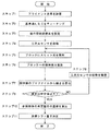
次に、図4のフローチャートを参照して本実施例のアライメント方法の手順を説明する。 Next, the procedure of the alignment method of this embodiment will be described with reference to the flowchart of FIG.
まず、アライメント用の治具を用意する。アライメント用の治具5は、板状部材51と、該板状部材51の上に固定されたブロック52を含む。図5に示すように、板状部材51は、その上面が、ロボット2の動作点20を動作させる空間の座標系である動作空間座標系の二軸(X軸及びY軸)を含む平面と合致する位置に固定される。また、板状部材51の上面の、動作空間座標系の原点に対応する位置に基準点Aを、動作空間座標系のX軸上の所定の位置に基準点Bを、動作空間座標系のY軸上の所定の位置に基準点Cを、それぞれ設定する。即ち、基準点A及びBにより動作空間座標系のX軸方向が規定され、基準点A及びCにより動作空間座標系のY軸が規定される。
First, a jig for alignment is prepared. The
ブロック52の大きさは、X軸方向の長さがW(mm)、Y軸方向の長さがL(mm)、Z軸方向の長さがH(mm)である。ブロック52のX軸方向の長さは、エリアセンサ42の視野に入る範囲内で、できるだけ長いことが好ましい。これにより、後述する処理を行う際にブロック52の上面に映るスリット光の投映線が長くなり、ブロック52に対する三次元センサ4の姿勢を求める際の精度が高くなる。
The size of the
一方、ブロック52のY軸方向の長さは、例えば10〜100mmであり、ロボットの大きさ等を考慮して適宜に決めればよい。ブロック52のY軸方向を長くすることにより、ブロック52にスリット光を照射したときにスリット光の投映線とブロック52の一辺(動作空間座標系のX軸に平行な辺)が平行であるか否かを視認しやすくなるためである。ただし、ブロック52のY軸方向を短くすると、スリット光の投映線がブロック52の一辺(動作空間座標系のX軸に平行な辺)を横切ってしまい、ブロック52の上面を横断する投映線を得ることが難しくなる。
On the other hand, the length of the
従来の座標系のアライメント方法では、動作点を正確に位置させるために可能な限り先端が尖った治具を用いることがあったが、先端が尖った治具を用いると光の拡散反射が生じやすく、動作点と治具の先端の位置関係を確認する際の撮像が困難になる場合があった。これに対し、本実施例では後述する方法及び装置によって座標系のアライメントを行うため、先端が尖った治具を用いる必要がなく、直方体状のブロック52を用いればよいため拡散反射は生じず、容易かつ正確に後述する投映線等が撮像される。
In the conventional coordinate system alignment method, a jig with a sharp tip was used as much as possible in order to accurately position the operating point, but using a jig with a sharp tip caused diffuse reflection of light In some cases, imaging when confirming the positional relationship between the operating point and the tip of the jig becomes difficult. On the other hand, in the present embodiment, the alignment of the coordinate system is performed by a method and an apparatus described later, so that it is not necessary to use a jig having a sharp tip, and diffuse reflection does not occur because a
また、ブロック52の表面には、光の乱反射を抑えるための、つや消し処理が施されている。ブロック52には、例えばつや消しアルマイトからなるものを好適に用いることができる。ブロック52は、動作空間座標系において該ブロック52の底面の中心が予め決められた座標に位置するように、動作空間座標系の三軸に平行に配置される。こうしてアライメント用の治具が設置される(ステップ1。図5参照)。
Further, the surface of the
続いて、コントローラ3によりアーム部21を動かし、動作点20を基準点Aに移動させ、ロボット2に基準点Aの位置をティーチングする。同様に、動作点20を基準点B及びCにも移動させ、それらの位置をロボット2にティーチングする(ステップ2)。このとき、コントローラ3を使用者が自ら操作してもよく、あるいは動作空間座標系設定部31により動作点20を各基準点に移動させてもよい。その後、動作空間座標系設定部31は、基準点A、B、及びCの、動作空間座標系における座標をロボット2に登録し、該ロボット2に予め(例えば出荷時に)登録されているロボット座標系と動作空間座標系の関係を決定する。こうして、ロボット2に動作空間座標系が設定される(ステップ3)。
Subsequently, the
ロボット2に動作空間座標系を設定した後、コントローラ3によりアーム部21を移動し、図5(ロボット2のうちアーム部21以外の図示を省略)に示すように、三次元センサ4をブロック52の上方に位置させる(ステップ4)。続いて、スリット光照射部41からブロック52に対してスリット光を照射し(ステップ5)、エリアセンサ42によりブロック52への投映線を取得する(ステップ6)。
After setting the motion space coordinate system for the
本実施例におけるスリット光は、三次元センサ4の出力信号の基準となる計測器座標系の一軸(X'軸)方向に幅を持つ光であり、該計測器座標系の別の一軸(Z'軸)方向に発せられる。即ち、計測器座標系のX'-Z'平面に沿ったシート状のスリット光である(図6参照)。本実施例の三次元センサ4は、該センサ4が有する光学系に含まれるレンズによって生じる収差や奥行き収差(カメラを斜め方向に向けたときに画角内で遠近法により生じる収差)を補正する。具体的には、二次元的に配列された画素のどの位置にスリット光が入射しているかを特定し、続いてその位置をキャリブレーションにより補正する。そして補正後の画素の位置から投映線のプロファイルを取得する。
The slit light in the present embodiment is light having a width in the direction of one axis (X ′ axis) of a measuring instrument coordinate system serving as a reference of the output signal of the three-
上述のとおり、ブロック52の三辺は動作空間座標系の三軸に平行に配置されており、また、スリット光はX'-Z'平面に沿ったシート状の光である。従って、動作空間座標系のX軸、Y軸、及びZ軸と、計測器座標系のX’軸、Y’軸、及びZ’軸がそれぞれ平行になっていると、ブロック52の上面への投映線は該ブロック52のX軸に平行な一辺の長さWと同一になる。また、ブロック52の上面への投映線と、板状部材51への投映線の間の距離は、ブロック52の高さH(及び三次元センサ4のエリアセンサ42がブロック及び板状部材51を捉える角度)に応じたものとなる。
As described above, the three sides of the
一方、計測器座標系が動作空間座標系に対して傾いている場合には、上記と異なる長さ及び距離を有する投映線が現れる。そうした場合に現れる、投映線について、図6及び7を参照して説明する。図6は、治具5(板状部材51及びブロック52)を基準にスリット光が斜方から照射された状態を示している。なお、図6では、角度α、β、及びγを分かりやすくするため、これらの角度を実際よりも大きくして投映線を示している。図7は、エリアセンサ42により計測された投映線に基づいて作成された表示例である。
On the other hand, when the measuring instrument coordinate system is inclined with respect to the motion space coordinate system, a projection line having a different length and distance from the above appears. The projection line that appears in such a case will be described with reference to FIGS. FIG. 6 shows a state in which slit light is applied obliquely with respect to the jig 5 (the
本実施例の場合、エリアセンサ42がX’-Z'平面に対して角度θ2傾いた位置に配置され、斜め上方から投映線を撮影する。そのため、エリアセンサ42により捉えられる、ブロック52の上面への投映線と板状部材51への投映線の間の距離は実際よりも短くなる。そこで、投映線取得部432は、スリット光照射部41及びエリアセンサ42の配置(X’-Z’平面に対する角度θ1及びθ2)及び実際に計測された上記距離に基づいて該距離を補正し測定値hを求める。一方、ブロック52の上面への投映線の長さはそのまま測定値wとする。そして、図7に示すように測定値w, hを表示部7に表示する。
In this embodiment, the
ここで、図6及び7に示すように、ブロック52の上面への投映線の一端(ブロック52の側面への投映線も撮影されている場合は投映線の屈曲点)を通り計測器座標系のZ‘軸に平行な直線と、該一端を通り動作空間座標系のZ軸と平行な直線とがなす角度をα、エリアセンサ42の画角の一方向(横方向)と該エリアセンサ42で捉えられた投映線がなす角度をβ、ブロック52の上面への投映線と、該投映線の一端を通り動作空間座標系のX軸に平行な直線がなす角度をγ、と規定する。
Here, as shown in FIGS. 6 and 7, one end of the projection line on the upper surface of the block 52 (the bending point of the projection line when the projection line on the side surface of the
上記のように角度α、β、及びγを規定すると、ブロック52のX軸方向の長さW及びZ軸方向の長さHと、上記測定値w及びhとから、次式により角度α及びγが求められる。
α=cos-1(H/h)…(1)
γ=cos-1(W/w)…(2)
また、角度βは、上記の通りエリアセンサ42画角の横方向と、板状部材51への投映線がなす角度として求められる。
When the angles α, β, and γ are defined as described above, the angle α and the angle α and the length H in the X-axis direction of the
α = cos -1 (H / h)… (1)
γ = cos -1 (W / w)… (2)
The angle β is determined as the angle between the horizontal direction of the angle of view of the
計測器姿勢算出部433は、上記のようにして投映線のプロファイルから上記の角度α、β、及びγを算出し(ステップ7)、表示部7の画面にそれぞれの角度を表示する。
The measuring instrument
上記角度α、β、及びγを算出すると、計測器姿勢算出部433は、それらの値が全て予め決められた値(所定値)以下であるかを判定する(ステップ8)。この所定値は、動作空間座標系の各軸と計測器座標系の各軸とが実質的に互いに平行であるであるとみなせる値に設定される。所定値は、例えば0.2度である。角度α、β、及びγが全て所定値以下であれば(ステップ8でYES)、後述するステップ10に進む。
After calculating the angles α, β, and γ, the measuring instrument
一方、いずれかの角度が所定値を上回っている場合には(ステップ8でNO)、使用者がコントローラ3を用いて三次元センサ4の姿勢を調整する(ステップ9)。そして、ステップ5に戻って再びブロック52にスリット光を照射し、上記角度α、β、及びγを算出して表示部7に表示するとともに、それらが全て所定値以下であるかを判定する(ステップ5〜8)。これらの処理は、角度α、β、及びγが全て所定値以下になるまで繰り返し行う。本実施例では、角度α、β、及びγを算出するごとに表示部7にそれらの値が表示されるため、使用者は角度α、β、及びγを確認し、計測器座標と動作空間座標がどの程度ずれているのかを直感的に把握することができる。また、その値の変化を確認しながら、ロボット2を用いて行おうとしている作業に求められる精度を考慮するなどして、どの程度まで両座標を合致させる必要があるかを判断することもできる。
On the other hand, if any of the angles exceeds the predetermined value (NO in step 8), the user adjusts the attitude of the three-
上記角度α、β、及びγが全て所定値以下になると(ステップ8でYES)、座標系シフト部434は、三次元センサからのスリット光をY'軸(動作空間座標系と計測器座標系が相互に平行であるため実質的にY軸と同じ)方向に走査してブロック52全体三次元データを取得し、ブロック52の所定の位置(例えば動作空間座標系のX-Y平面上に位置する、ブロック52の底面の中心)の、計測器座標系における座標位置を求める(ステップ10)。そして、動作空間座標系におけるブロック52の上記所定の位置座標位置と比較して差分(シフト量)を求める(ステップ11)。最後に、計測器座標系を上記シフト量の大きさだけシフトさせることにより、計測器座標系と動作空間座標系を合致させる。
When the angles α, β, and γ are all equal to or smaller than predetermined values (YES in step 8), the coordinate
上記実施例で説明した具体的な構成や数値はいずれも一例であって、本発明の趣旨に沿って適宜に変更することができる。
上記実施例では、治具5を使用して両座標系のシフト量を求めた、同座標系をシフトさせて一致させる処理まで行ったが、これらの処理は必須ではない。例えば、実際にロボットを動作させる際に、計測器座標系で取得された位置に上記シフト量を加えて(あるいは減じて)動作空間座標系の位置に変換する処理を、実際にロボットを動作させる毎に行ってもよい。あるいは、動作空間座標系の三軸と計測器座標系の三軸を互いに平行にした後、別の治具を配置し、動作空間座標系と計測器座標系のそれぞれにおける、その治具の所定位置の座標の差からシフト量を求めることもできる。シフト量を求めるために使用する治具は必ずしも直方体状のものである必要はなく、上記所定位置を規定可能な適宜の形状のものを用いることができる。例えば、直方体状のブロック52の全体のプロファイルを取得する際にエッジ部分の形状を正確に計測することが難しい場合には、円筒状のブロックを用いるとよい。また、シフト量の算出に用いる治具はブロックに限らず、所定位置(例えばX-Y平面上に位置する中心と該中心からの高さの座標が既知であり、三次元センサ4によって三次元データを取得可能な、適宜のものを用いることができる。
The specific configurations and numerical values described in the above embodiments are merely examples, and can be appropriately changed in accordance with the gist of the present invention.
In the above-described embodiment, the shift amounts of the two coordinate systems are obtained by using the
現在、製造業の現場では、人口の減少により、人力に代わるロボットの普及が急務とされている。しかし、ロボットと三次元計測器を使ったシステムの統合には高度な知識が必要とされるため、現場の作業員にとって必ずしも容易ではない。特に、様々なロボットメーカにより製造されたロボットが用いられる自動車産業などでは、ロボットメーカによって操作性が異なるために、その操作を熟知した専門の技術者の派遣が必要となる場合があり、人材の確保が難しく、また人材の育成も難しい。例えば、ロボットの使用中に、予期しない衝突等が起こり三次元計測器の取り付け位置がずれてしまうことがある。現場では速やかな復旧が求められるため、高度な知識を有することなく様々なロボットメーカにより製造されたロボットに共通して適用可能なアライメント技術が必要とされており、本発明を好適に用いることができる。 At present, in the field of the manufacturing industry, the spread of robots instead of human power is urgently required due to the declining population. However, integration of a system using a robot and a three-dimensional measuring device requires a high level of knowledge, and is not always easy for on-site workers. In particular, in the automotive industry where robots manufactured by various robot manufacturers are used, the operability differs depending on the robot manufacturer, and it may be necessary to dispatch a specialized technician who is familiar with the operation. It is difficult to secure and to develop human resources. For example, during use of the robot, an unexpected collision or the like may occur, and the mounting position of the three-dimensional measuring device may be shifted. Since quick recovery is required at the site, there is a need for an alignment technique that can be commonly applied to robots manufactured by various robot manufacturers without having advanced knowledge, and it is preferable to use the present invention suitably. it can.
1…ロボットシステム
2…ロボット
20…動作点
21…アーム部
22a〜22c…直動機構
23a〜23c…回転機構
3…コントローラ
31…動作空間座標系設定部
4…三次元センサ
41…スリット光照射部
42…エリアセンサ
43…制御・処理部
431…記憶部
432…投映線取得部
433…計測器姿勢算出部
44…通信インターフェース
5…治具
51…板状部材
52…ブロック
6…入力部
7…表示部
DESCRIPTION OF SYMBOLS 1 ...
Claims (9)
前記動作点の動作空間の座標系である動作空間座標系における原点に位置する第1基準点、該第1基準点で直交する2つの直線上にそれぞれ位置する第2基準点及び第3基準点に前記動作点を移動させて各基準点の位置をティーチングすることにより、前記動作空間座標系と前記ロボット座標系の関係を決定し、
前記動作空間座標系を規定する直交三軸のうちの二軸が載る平面に対して平行に配置された板状部材の表面に、該直交三軸のそれぞれに対して各辺が平行になるように固定された直方体状の参照物体に対し、前記三次元計測器からシート状のスリット光を照射して、該スリット光による前記参照物体への投映線を取得し、
前記投映線のプロファイルに基づいて、前記参照物体に対する前記三次元計測器の姿勢を求め、
前記三次元計測器の姿勢が所定の基準姿勢範囲内に入るように前記三次元計測器を移動させる
工程を有することを特徴とするロボット用の座標系アライメント方法。 A robot coordinate system that is a robot coordinate system for moving an operating point three-dimensionally; and a coordinate system of a three-dimensional measuring device that can execute a light-section method and has a constant position and orientation with respect to the operating point. A method for aligning a measuring instrument coordinate system, comprising:
A first reference point located at the origin in an operation space coordinate system which is a coordinate system of the operation space of the operation point; a second reference point and a third reference point respectively located on two straight lines orthogonal to the first reference point By moving the operating point to teach the position of each reference point, the relationship between the operating space coordinate system and the robot coordinate system is determined,
On the surface of a plate-shaped member arranged in parallel to a plane on which two of the three orthogonal axes defining the motion space coordinate system are placed, each side is parallel to each of the three orthogonal axes. For a rectangular parallelepiped reference object fixed to, irradiating a sheet-like slit light from the three-dimensional measuring device, to obtain a projection line to the reference object by the slit light,
Based on the profile of the projection line, determine the orientation of the three-dimensional measuring device with respect to the reference object,
Moving the three-dimensional measuring device such that the posture of the three-dimensional measuring device falls within a predetermined reference posture range.
前記参照物体の所定位置の、前記動作空間座標系における座標と、前記計測器座標系における座標を比較して差分を求め、
前記計測器座標系を前記差分だけシフトさせる
工程を有することを特徴とする請求項1に記載のロボット用の座標系アライメント方法。 After moving the three-dimensional measuring device so that the posture of the three-dimensional measuring device falls within a predetermined reference posture range, further,
A predetermined position of the reference object is compared with coordinates in the motion space coordinate system, and a difference is obtained by comparing coordinates in the measuring device coordinate system.
The method according to claim 1, further comprising: shifting the measuring instrument coordinate system by the difference.
前記動作点の動作空間の座標系である動作空間座標系における原点に位置する第1基準点、該第1基準点を通り直交する2つの直線上にそれぞれ位置する第2基準点、及び第3基準点に前記動作点を移動させて各基準点の位置をティーチングすることにより、前記動作空間座標系と前記ロボット座標系の関係を決定する動作空間座標系設定部と、
前記動作空間座標系を規定する直交三軸のうちの二軸が載る平面に対して平行に配置された板状部材の表面に、該直交三軸のそれぞれに対して各辺が平行になるように固定された直方体状の参照物体に対し、前記三次元計測器からシート状のスリット光を照射して、該スリット光による前記参照物体への投映線を取得する投映線取得部と、
前記投映線のプロファイルに基づいて、前記参照物体に対する前記三次元計測器の姿勢を求める計測器姿勢算出部と、
前記三次元計測器を移動させる計測器移動部と
を備えることを特徴とするロボット用の座標系アライメントシステム。 A robot coordinate system that is a robot coordinate system for moving an operating point three-dimensionally; and a coordinate system of a three-dimensional measuring device that can execute a light-section method and has a constant position and orientation with respect to the operating point. A system for aligning a measuring instrument coordinate system,
A first reference point located at the origin in an operation space coordinate system that is a coordinate system of the operation space of the operation point, a second reference point located on two orthogonal lines passing through the first reference point, and a third reference point By moving the operation point to a reference point and teaching the position of each reference point, an operation space coordinate system setting unit that determines the relationship between the operation space coordinate system and the robot coordinate system,
On the surface of a plate-shaped member arranged in parallel to a plane on which two of the three orthogonal axes defining the motion space coordinate system are placed, each side is parallel to each of the three orthogonal axes. For a rectangular parallelepiped reference object fixed to, irradiating a sheet-like slit light from the three-dimensional measuring device, a projection line acquisition unit for acquiring a projection line to the reference object by the slit light,
Based on the profile of the projection line, a measuring instrument attitude calculation unit that determines the attitude of the three-dimensional measuring instrument with respect to the reference object,
A coordinate system alignment system for a robot, comprising: a measuring device moving unit configured to move the three-dimensional measuring device.
前記動作空間座標系を規定する直交三軸のうちの二軸が載る平面に対して平行に配置された板状部材の表面に、該直交三軸のそれぞれに対して各辺が平行になるように固定された直方体状の参照物体に対し、前記三次元計測器からシート状のスリット光を照射して、該スリット光による前記参照物体への投映線を取得する投映線取得部と、
前記投映線のプロファイルに基づいて、前記参照物体に対する前記三次元計測器の姿勢を求める計測器姿勢算出部と、
を備えることを特徴とするロボット用の座標系アライメント装置。 An operating space coordinate system, which is a coordinate system of the operating space of the operating point previously associated with a robot coordinate system, which is a robot coordinate system for moving the operating point three-dimensionally, can execute a light-section method. A device used for aligning a measuring instrument coordinate system, which is a coordinate system of a three-dimensional measuring instrument whose position and orientation with respect to the operating point are invariable,
On the surface of a plate-shaped member arranged in parallel to a plane on which two of the three orthogonal axes defining the motion space coordinate system are placed, each side is parallel to each of the three orthogonal axes. For a rectangular parallelepiped reference object fixed to, irradiating a sheet-like slit light from the three-dimensional measuring device, a projection line acquisition unit for acquiring a projection line to the reference object by the slit light,
Based on the profile of the projection line, a measuring instrument attitude calculation unit that determines the attitude of the three-dimensional measuring instrument with respect to the reference object,
A coordinate system alignment device for a robot, comprising:
前記参照物体の所定位置の、前記動作空間座標系における座標と、前記計測器座標系における座標を比較して差分を求め、前記計測器座標系を前記差分だけシフトさせる座標系シフト部
を備えることを特徴とする請求項7に記載のロボット用の座標系アライメント装置。 further,
A coordinate system shift unit that compares a coordinate of the predetermined position of the reference object in the motion space coordinate system with a coordinate in the measuring device coordinate system to obtain a difference, and shifts the measuring device coordinate system by the difference. The coordinate system alignment apparatus for a robot according to claim 7, wherein:
前記計測器姿勢算出部によって前記三次元計測器の姿勢が求められる毎に、前記参照物体に対する前記三次元計測器の姿勢を表示する表示部
を備えることを特徴とする請求項7又は8に記載のロボット用の座標系アライメント装置。 further,
The display unit that displays the posture of the three-dimensional measuring device with respect to the reference object every time the posture of the three-dimensional measuring device is obtained by the measuring device posture calculating unit. Coordinate system for robots.
Priority Applications (5)
| Application Number | Priority Date | Filing Date | Title |
|---|---|---|---|
| JP2019217775A JP6670974B1 (en) | 2019-12-02 | 2019-12-02 | Robot coordinate system alignment method, alignment system, and alignment device |
| JP2021562554A JP7273185B2 (en) | 2019-12-02 | 2020-11-17 | COORDINATE SYSTEM ALIGNMENT METHOD, ALIGNMENT SYSTEM AND ALIGNMENT APPARATUS FOR ROBOT |
| EP20896987.3A EP4070923A4 (en) | 2019-12-02 | 2020-11-17 | Coordinate system alignment method, alignment system, and alignment device for robot |
| US17/781,141 US12290924B2 (en) | 2019-12-02 | 2020-11-17 | Coordinate system alignment method, alignment system, and alignment device for robot |
| PCT/JP2020/042870 WO2021111868A1 (en) | 2019-12-02 | 2020-11-17 | Coordinate system alignment method, alignment system, and alignment device for robot |
Applications Claiming Priority (1)
| Application Number | Priority Date | Filing Date | Title |
|---|---|---|---|
| JP2019217775A JP6670974B1 (en) | 2019-12-02 | 2019-12-02 | Robot coordinate system alignment method, alignment system, and alignment device |
Publications (2)
| Publication Number | Publication Date |
|---|---|
| JP6670974B1 true JP6670974B1 (en) | 2020-03-25 |
| JP2021088003A JP2021088003A (en) | 2021-06-10 |
Family
ID=70000783
Family Applications (2)
| Application Number | Title | Priority Date | Filing Date |
|---|---|---|---|
| JP2019217775A Active JP6670974B1 (en) | 2019-12-02 | 2019-12-02 | Robot coordinate system alignment method, alignment system, and alignment device |
| JP2021562554A Active JP7273185B2 (en) | 2019-12-02 | 2020-11-17 | COORDINATE SYSTEM ALIGNMENT METHOD, ALIGNMENT SYSTEM AND ALIGNMENT APPARATUS FOR ROBOT |
Family Applications After (1)
| Application Number | Title | Priority Date | Filing Date |
|---|---|---|---|
| JP2021562554A Active JP7273185B2 (en) | 2019-12-02 | 2020-11-17 | COORDINATE SYSTEM ALIGNMENT METHOD, ALIGNMENT SYSTEM AND ALIGNMENT APPARATUS FOR ROBOT |
Country Status (4)
| Country | Link |
|---|---|
| US (1) | US12290924B2 (en) |
| EP (1) | EP4070923A4 (en) |
| JP (2) | JP6670974B1 (en) |
| WO (1) | WO2021111868A1 (en) |
Cited By (3)
| Publication number | Priority date | Publication date | Assignee | Title |
|---|---|---|---|---|
| CN112873264A (en) * | 2021-03-18 | 2021-06-01 | 中国工程物理研究院机械制造工艺研究所 | Industrial robot joint structure, robot control system and method |
| US20210373042A1 (en) * | 2020-05-29 | 2021-12-02 | Roche Diagnostics Operations, Inc. | Module for an automated laboratory system |
| CN114485427A (en) * | 2022-01-20 | 2022-05-13 | 上汽大众汽车有限公司 | Measuring reference construction method and system for measuring vehicle body size |
Families Citing this family (4)
| Publication number | Priority date | Publication date | Assignee | Title |
|---|---|---|---|---|
| JP7277340B2 (en) * | 2019-11-15 | 2023-05-18 | 川崎重工業株式会社 | Master-slave system, control method and control device |
| JP7367858B2 (en) * | 2020-03-30 | 2023-10-24 | 日本電気株式会社 | Imaging system, imaging method and imaging program |
| CN119610094A (en) * | 2024-12-03 | 2025-03-14 | 珠海格力智能装备有限公司 | Robot anti-collision method, device and robot control system |
| CN119704191B (en) * | 2024-12-31 | 2025-08-01 | 广东工业大学 | Calibration method, device and equipment for external actuator of robot |
Family Cites Families (13)
| Publication number | Priority date | Publication date | Assignee | Title |
|---|---|---|---|---|
| US5506683A (en) | 1990-04-30 | 1996-04-09 | Kumho & Co., Inc. | Non-contact measuring apparatus for the section profile of a tire and its method |
| JP3138080B2 (en) * | 1992-10-22 | 2001-02-26 | 株式会社豊田中央研究所 | Automatic calibration device for vision sensor |
| JP3644991B2 (en) * | 1994-11-08 | 2005-05-11 | ファナック株式会社 | Coordinate system coupling method in robot-sensor system |
| US6044308A (en) * | 1997-06-13 | 2000-03-28 | Huissoon; Jan Paul | Method and device for robot tool frame calibration |
| JPH1133962A (en) * | 1997-07-18 | 1999-02-09 | Yaskawa Electric Corp | Calibration of robot three-dimensional position sensor. Method and device. |
| JP2002172575A (en) * | 2000-12-07 | 2002-06-18 | Fanuc Ltd | Teaching device |
| JP2010091540A (en) | 2008-10-13 | 2010-04-22 | Toyota Motor Corp | System and method for three-dimensional measurement |
| EP2722640A4 (en) | 2011-06-20 | 2014-11-19 | Yaskawa Denki Seisakusho Kk | DEVICE FOR MEASURING A THREE DIMENSIONAL SHAPE AND ROBOTIC SYSTEM |
| US20160243703A1 (en) | 2015-02-19 | 2016-08-25 | Isios Gmbh | Arrangement and method for the model-based calibration of a robot in a working space |
| EP3147086B1 (en) | 2015-09-22 | 2020-11-04 | Airbus Defence and Space GmbH | Automation of robot operations in aircraft construction |
| JP6848269B2 (en) * | 2016-09-01 | 2021-03-24 | アイシン精機株式会社 | Palletizing device |
| JP6888580B2 (en) | 2018-04-05 | 2021-06-16 | オムロン株式会社 | Information processing equipment, information processing methods, and programs |
| CN111504183B (en) | 2020-04-22 | 2021-03-09 | 无锡中车时代智能装备有限公司 | Calibration method for relative position of linear laser three-dimensional measurement sensor and robot |
-
2019
- 2019-12-02 JP JP2019217775A patent/JP6670974B1/en active Active
-
2020
- 2020-11-17 EP EP20896987.3A patent/EP4070923A4/en active Pending
- 2020-11-17 US US17/781,141 patent/US12290924B2/en active Active
- 2020-11-17 JP JP2021562554A patent/JP7273185B2/en active Active
- 2020-11-17 WO PCT/JP2020/042870 patent/WO2021111868A1/en not_active Ceased
Cited By (6)
| Publication number | Priority date | Publication date | Assignee | Title |
|---|---|---|---|---|
| US20210373042A1 (en) * | 2020-05-29 | 2021-12-02 | Roche Diagnostics Operations, Inc. | Module for an automated laboratory system |
| US12253535B2 (en) * | 2020-05-29 | 2025-03-18 | Roche Diagnostics Operations, Inc. | Module for an automated laboratory system |
| CN112873264A (en) * | 2021-03-18 | 2021-06-01 | 中国工程物理研究院机械制造工艺研究所 | Industrial robot joint structure, robot control system and method |
| CN112873264B (en) * | 2021-03-18 | 2024-02-23 | 中国工程物理研究院机械制造工艺研究所 | Industrial robot joint structure, robot control system and method |
| CN114485427A (en) * | 2022-01-20 | 2022-05-13 | 上汽大众汽车有限公司 | Measuring reference construction method and system for measuring vehicle body size |
| CN114485427B (en) * | 2022-01-20 | 2023-09-22 | 上汽大众汽车有限公司 | A measurement reference construction method and system for vehicle body size measurement |
Also Published As
| Publication number | Publication date |
|---|---|
| EP4070923A1 (en) | 2022-10-12 |
| EP4070923A4 (en) | 2024-01-03 |
| JPWO2021111868A1 (en) | 2021-06-10 |
| WO2021111868A1 (en) | 2021-06-10 |
| US20220410375A1 (en) | 2022-12-29 |
| US12290924B2 (en) | 2025-05-06 |
| JP2021088003A (en) | 2021-06-10 |
| JP7273185B2 (en) | 2023-05-12 |
Similar Documents
| Publication | Publication Date | Title |
|---|---|---|
| JP6670974B1 (en) | Robot coordinate system alignment method, alignment system, and alignment device | |
| KR102532072B1 (en) | System and method for automatic hand-eye calibration of vision system for robot motion | |
| JP4021413B2 (en) | Measuring device | |
| JP4191080B2 (en) | Measuring device | |
| KR101636605B1 (en) | System and method for calibration of machine vision cameras along at least three discrete planes | |
| US10618166B2 (en) | Teaching position correction device and teaching position correction method | |
| JP6280525B2 (en) | System and method for runtime determination of camera miscalibration | |
| JP6025386B2 (en) | Image measuring apparatus, image measuring method, and image measuring program | |
| JP2005342832A (en) | Robot system | |
| JP2016185572A (en) | Robot, robot controller and robot system | |
| JP6869159B2 (en) | Robot system | |
| EP3421930A1 (en) | Three-dimensional shape data and texture information generation system, photographing control program, and three-dimensional shape data and texture information generation method | |
| US20190255706A1 (en) | Simulation device that simulates operation of robot | |
| US20240070910A1 (en) | Processing method and processing device for generating cross-sectional image from three-dimensional position information acquired by visual sensor | |
| JP2019063955A (en) | Robot system, operation control method and operation control program | |
| KR20130075712A (en) | Laser vision sensor and its correction method | |
| US20240066701A1 (en) | Simulation device using three-dimensional position information obtained from output from vision sensor | |
| TW202241660A (en) | Program generation device and robot control device | |
| CN115362049B (en) | Device for correcting the teaching position of a robot, teaching device, robot system, teaching position correction method, and computer program | |
| CN115397626A (en) | Coordinate system setting system and position and orientation measuring system | |
| JP2016187851A (en) | Calibration device | |
| WO2025210276A1 (en) | Method and device for determining the orienting of a surface of a workpiece and method for orienting a device at the point of work at the surface of the workpiece | |
| JP2025171459A (en) | Method and apparatus for determining the position and attitude of an object |
Legal Events
| Date | Code | Title | Description |
|---|---|---|---|
| A621 | Written request for application examination |
Free format text: JAPANESE INTERMEDIATE CODE: A621 Effective date: 20191202 |
|
| A871 | Explanation of circumstances concerning accelerated examination |
Free format text: JAPANESE INTERMEDIATE CODE: A871 Effective date: 20191202 |
|
| RD01 | Notification of change of attorney |
Free format text: JAPANESE INTERMEDIATE CODE: A7426 Effective date: 20200108 |
|
| A975 | Report on accelerated examination |
Free format text: JAPANESE INTERMEDIATE CODE: A971005 Effective date: 20200122 |
|
| TRDD | Decision of grant or rejection written | ||
| A521 | Request for written amendment filed |
Free format text: JAPANESE INTERMEDIATE CODE: A821 Effective date: 20200108 |
|
| A01 | Written decision to grant a patent or to grant a registration (utility model) |
Free format text: JAPANESE INTERMEDIATE CODE: A01 Effective date: 20200204 |
|
| A61 | First payment of annual fees (during grant procedure) |
Free format text: JAPANESE INTERMEDIATE CODE: A61 Effective date: 20200302 |
|
| R150 | Certificate of patent or registration of utility model |
Ref document number: 6670974 Country of ref document: JP Free format text: JAPANESE INTERMEDIATE CODE: R150 |
|
| R250 | Receipt of annual fees |
Free format text: JAPANESE INTERMEDIATE CODE: R250 |
|
| R250 | Receipt of annual fees |
Free format text: JAPANESE INTERMEDIATE CODE: R250 |
|
| R250 | Receipt of annual fees |
Free format text: JAPANESE INTERMEDIATE CODE: R250 |