JP6657262B2 - Sample support and analysis system for performing specified reaction - Google Patents
Sample support and analysis system for performing specified reaction Download PDFInfo
- Publication number
- JP6657262B2 JP6657262B2 JP2017561714A JP2017561714A JP6657262B2 JP 6657262 B2 JP6657262 B2 JP 6657262B2 JP 2017561714 A JP2017561714 A JP 2017561714A JP 2017561714 A JP2017561714 A JP 2017561714A JP 6657262 B2 JP6657262 B2 JP 6657262B2
- Authority
- JP
- Japan
- Prior art keywords
- temperature control
- control block
- sample support
- chamber
- analysis system
- Prior art date
- Legal status (The legal status is an assumption and is not a legal conclusion. Google has not performed a legal analysis and makes no representation as to the accuracy of the status listed.)
- Active
Links
- 238000006243 chemical reaction Methods 0.000 title claims description 317
- 238000004458 analytical method Methods 0.000 title claims description 170
- 239000000758 substrate Substances 0.000 claims description 154
- 239000012530 fluid Substances 0.000 claims description 149
- 125000006850 spacer group Chemical group 0.000 claims description 60
- 238000000034 method Methods 0.000 claims description 58
- 239000000126 substance Substances 0.000 claims description 49
- 239000007788 liquid Substances 0.000 claims description 46
- 238000012546 transfer Methods 0.000 claims description 30
- 238000003825 pressing Methods 0.000 claims description 26
- 238000001816 cooling Methods 0.000 claims description 24
- 238000007901 in situ hybridization Methods 0.000 claims description 18
- 230000008878 coupling Effects 0.000 claims description 15
- 238000010168 coupling process Methods 0.000 claims description 15
- 238000005859 coupling reaction Methods 0.000 claims description 15
- 238000004891 communication Methods 0.000 claims description 13
- 238000011532 immunohistochemical staining Methods 0.000 claims description 13
- 238000001514 detection method Methods 0.000 claims description 11
- 239000011888 foil Substances 0.000 claims description 6
- 230000007246 mechanism Effects 0.000 claims description 6
- 239000003153 chemical reaction reagent Substances 0.000 claims description 5
- 230000006698 induction Effects 0.000 claims description 4
- 238000012545 processing Methods 0.000 claims description 4
- 238000009396 hybridization Methods 0.000 claims 1
- 239000000523 sample Substances 0.000 description 379
- 210000004027 cell Anatomy 0.000 description 248
- 239000010410 layer Substances 0.000 description 218
- 230000000875 corresponding effect Effects 0.000 description 143
- 238000002493 microarray Methods 0.000 description 45
- 238000011144 upstream manufacturing Methods 0.000 description 35
- 108020004707 nucleic acids Proteins 0.000 description 24
- 102000039446 nucleic acids Human genes 0.000 description 24
- 150000007523 nucleic acids Chemical class 0.000 description 24
- 125000003729 nucleotide group Chemical group 0.000 description 20
- 239000012491 analyte Substances 0.000 description 18
- 239000002773 nucleotide Substances 0.000 description 18
- 230000015654 memory Effects 0.000 description 17
- 238000003491 array Methods 0.000 description 15
- 239000012472 biological sample Substances 0.000 description 15
- 230000003287 optical effect Effects 0.000 description 15
- 238000003860 storage Methods 0.000 description 13
- 230000006870 function Effects 0.000 description 12
- 239000000463 material Substances 0.000 description 12
- 238000012163 sequencing technique Methods 0.000 description 12
- 239000007789 gas Substances 0.000 description 11
- 239000000853 adhesive Substances 0.000 description 10
- 230000001070 adhesive effect Effects 0.000 description 10
- 238000010586 diagram Methods 0.000 description 10
- 239000000243 solution Substances 0.000 description 10
- 239000011324 bead Substances 0.000 description 9
- 230000003321 amplification Effects 0.000 description 8
- 210000001124 body fluid Anatomy 0.000 description 8
- 238000003199 nucleic acid amplification method Methods 0.000 description 8
- 230000001276 controlling effect Effects 0.000 description 7
- 210000004369 blood Anatomy 0.000 description 6
- 239000008280 blood Substances 0.000 description 6
- 239000010839 body fluid Substances 0.000 description 6
- 230000005484 gravity Effects 0.000 description 6
- 239000011859 microparticle Substances 0.000 description 6
- 210000001519 tissue Anatomy 0.000 description 6
- 230000015572 biosynthetic process Effects 0.000 description 5
- 239000007850 fluorescent dye Substances 0.000 description 5
- 230000001965 increasing effect Effects 0.000 description 5
- PHIYHIOQVWTXII-UHFFFAOYSA-N 3-amino-1-phenylpropan-1-ol Chemical compound NCCC(O)C1=CC=CC=C1 PHIYHIOQVWTXII-UHFFFAOYSA-N 0.000 description 4
- -1 antibodies Substances 0.000 description 4
- 239000013592 cell lysate Substances 0.000 description 4
- 230000008859 change Effects 0.000 description 4
- 238000010438 heat treatment Methods 0.000 description 4
- 230000000670 limiting effect Effects 0.000 description 4
- 239000002184 metal Substances 0.000 description 4
- 210000000056 organ Anatomy 0.000 description 4
- 210000002381 plasma Anatomy 0.000 description 4
- 230000002441 reversible effect Effects 0.000 description 4
- 210000002966 serum Anatomy 0.000 description 4
- 238000003786 synthesis reaction Methods 0.000 description 4
- 238000005516 engineering process Methods 0.000 description 3
- 239000010419 fine particle Substances 0.000 description 3
- 238000003384 imaging method Methods 0.000 description 3
- 230000003993 interaction Effects 0.000 description 3
- 239000004033 plastic Substances 0.000 description 3
- 229920003023 plastic Polymers 0.000 description 3
- 238000002360 preparation method Methods 0.000 description 3
- 230000008569 process Effects 0.000 description 3
- 238000007493 shaping process Methods 0.000 description 3
- 239000002356 single layer Substances 0.000 description 3
- 241000894007 species Species 0.000 description 3
- HNXRLRRQDUXQEE-ALURDMBKSA-N (2s,3r,4s,5r,6r)-2-[[(2r,3s,4r)-4-hydroxy-2-(hydroxymethyl)-3,4-dihydro-2h-pyran-3-yl]oxy]-6-(hydroxymethyl)oxane-3,4,5-triol Chemical compound O[C@@H]1[C@@H](O)[C@@H](O)[C@@H](CO)O[C@H]1O[C@@H]1[C@@H](CO)OC=C[C@H]1O HNXRLRRQDUXQEE-ALURDMBKSA-N 0.000 description 2
- 229920002799 BoPET Polymers 0.000 description 2
- 239000003155 DNA primer Substances 0.000 description 2
- 102000016928 DNA-directed DNA polymerase Human genes 0.000 description 2
- 108010014303 DNA-directed DNA polymerase Proteins 0.000 description 2
- 102000004190 Enzymes Human genes 0.000 description 2
- 108090000790 Enzymes Proteins 0.000 description 2
- 101100521334 Mus musculus Prom1 gene Proteins 0.000 description 2
- 108091034117 Oligonucleotide Proteins 0.000 description 2
- 208000002151 Pleural effusion Diseases 0.000 description 2
- 229920000388 Polyphosphate Polymers 0.000 description 2
- 206010036790 Productive cough Diseases 0.000 description 2
- JLCPHMBAVCMARE-UHFFFAOYSA-N [3-[[3-[[3-[[3-[[3-[[3-[[3-[[3-[[3-[[3-[[3-[[5-(2-amino-6-oxo-1H-purin-9-yl)-3-[[3-[[3-[[3-[[3-[[3-[[5-(2-amino-6-oxo-1H-purin-9-yl)-3-[[5-(2-amino-6-oxo-1H-purin-9-yl)-3-hydroxyoxolan-2-yl]methoxy-hydroxyphosphoryl]oxyoxolan-2-yl]methoxy-hydroxyphosphoryl]oxy-5-(5-methyl-2,4-dioxopyrimidin-1-yl)oxolan-2-yl]methoxy-hydroxyphosphoryl]oxy-5-(6-aminopurin-9-yl)oxolan-2-yl]methoxy-hydroxyphosphoryl]oxy-5-(6-aminopurin-9-yl)oxolan-2-yl]methoxy-hydroxyphosphoryl]oxy-5-(6-aminopurin-9-yl)oxolan-2-yl]methoxy-hydroxyphosphoryl]oxy-5-(6-aminopurin-9-yl)oxolan-2-yl]methoxy-hydroxyphosphoryl]oxyoxolan-2-yl]methoxy-hydroxyphosphoryl]oxy-5-(5-methyl-2,4-dioxopyrimidin-1-yl)oxolan-2-yl]methoxy-hydroxyphosphoryl]oxy-5-(4-amino-2-oxopyrimidin-1-yl)oxolan-2-yl]methoxy-hydroxyphosphoryl]oxy-5-(5-methyl-2,4-dioxopyrimidin-1-yl)oxolan-2-yl]methoxy-hydroxyphosphoryl]oxy-5-(5-methyl-2,4-dioxopyrimidin-1-yl)oxolan-2-yl]methoxy-hydroxyphosphoryl]oxy-5-(6-aminopurin-9-yl)oxolan-2-yl]methoxy-hydroxyphosphoryl]oxy-5-(6-aminopurin-9-yl)oxolan-2-yl]methoxy-hydroxyphosphoryl]oxy-5-(4-amino-2-oxopyrimidin-1-yl)oxolan-2-yl]methoxy-hydroxyphosphoryl]oxy-5-(4-amino-2-oxopyrimidin-1-yl)oxolan-2-yl]methoxy-hydroxyphosphoryl]oxy-5-(4-amino-2-oxopyrimidin-1-yl)oxolan-2-yl]methoxy-hydroxyphosphoryl]oxy-5-(6-aminopurin-9-yl)oxolan-2-yl]methoxy-hydroxyphosphoryl]oxy-5-(4-amino-2-oxopyrimidin-1-yl)oxolan-2-yl]methyl [5-(6-aminopurin-9-yl)-2-(hydroxymethyl)oxolan-3-yl] hydrogen phosphate Polymers Cc1cn(C2CC(OP(O)(=O)OCC3OC(CC3OP(O)(=O)OCC3OC(CC3O)n3cnc4c3nc(N)[nH]c4=O)n3cnc4c3nc(N)[nH]c4=O)C(COP(O)(=O)OC3CC(OC3COP(O)(=O)OC3CC(OC3COP(O)(=O)OC3CC(OC3COP(O)(=O)OC3CC(OC3COP(O)(=O)OC3CC(OC3COP(O)(=O)OC3CC(OC3COP(O)(=O)OC3CC(OC3COP(O)(=O)OC3CC(OC3COP(O)(=O)OC3CC(OC3COP(O)(=O)OC3CC(OC3COP(O)(=O)OC3CC(OC3COP(O)(=O)OC3CC(OC3COP(O)(=O)OC3CC(OC3COP(O)(=O)OC3CC(OC3COP(O)(=O)OC3CC(OC3COP(O)(=O)OC3CC(OC3COP(O)(=O)OC3CC(OC3CO)n3cnc4c(N)ncnc34)n3ccc(N)nc3=O)n3cnc4c(N)ncnc34)n3ccc(N)nc3=O)n3ccc(N)nc3=O)n3ccc(N)nc3=O)n3cnc4c(N)ncnc34)n3cnc4c(N)ncnc34)n3cc(C)c(=O)[nH]c3=O)n3cc(C)c(=O)[nH]c3=O)n3ccc(N)nc3=O)n3cc(C)c(=O)[nH]c3=O)n3cnc4c3nc(N)[nH]c4=O)n3cnc4c(N)ncnc34)n3cnc4c(N)ncnc34)n3cnc4c(N)ncnc34)n3cnc4c(N)ncnc34)O2)c(=O)[nH]c1=O JLCPHMBAVCMARE-UHFFFAOYSA-N 0.000 description 2
- 210000004381 amniotic fluid Anatomy 0.000 description 2
- 239000000427 antigen Substances 0.000 description 2
- 102000036639 antigens Human genes 0.000 description 2
- 108091007433 antigens Proteins 0.000 description 2
- 239000000872 buffer Substances 0.000 description 2
- 150000001720 carbohydrates Chemical class 0.000 description 2
- 235000014633 carbohydrates Nutrition 0.000 description 2
- 230000001413 cellular effect Effects 0.000 description 2
- 210000001175 cerebrospinal fluid Anatomy 0.000 description 2
- 239000012459 cleaning agent Substances 0.000 description 2
- 238000004590 computer program Methods 0.000 description 2
- 238000012864 cross contamination Methods 0.000 description 2
- 230000003247 decreasing effect Effects 0.000 description 2
- 230000000694 effects Effects 0.000 description 2
- 239000000839 emulsion Substances 0.000 description 2
- 238000011010 flushing procedure Methods 0.000 description 2
- 239000011521 glass Substances 0.000 description 2
- 150000004676 glycans Chemical class 0.000 description 2
- 238000007641 inkjet printing Methods 0.000 description 2
- 238000005304 joining Methods 0.000 description 2
- 239000003446 ligand Substances 0.000 description 2
- 150000002632 lipids Chemical class 0.000 description 2
- 210000002751 lymph Anatomy 0.000 description 2
- 230000003278 mimic effect Effects 0.000 description 2
- 238000012544 monitoring process Methods 0.000 description 2
- 239000002777 nucleoside Substances 0.000 description 2
- 125000003835 nucleoside group Chemical group 0.000 description 2
- 210000003463 organelle Anatomy 0.000 description 2
- 239000002245 particle Substances 0.000 description 2
- 229920000642 polymer Polymers 0.000 description 2
- 108091033319 polynucleotide Proteins 0.000 description 2
- 102000040430 polynucleotide Human genes 0.000 description 2
- 239000002157 polynucleotide Substances 0.000 description 2
- 229920001184 polypeptide Polymers 0.000 description 2
- 239000001205 polyphosphate Substances 0.000 description 2
- 235000011176 polyphosphates Nutrition 0.000 description 2
- 229920001282 polysaccharide Polymers 0.000 description 2
- 239000005017 polysaccharide Substances 0.000 description 2
- 102000004196 processed proteins & peptides Human genes 0.000 description 2
- 108090000765 processed proteins & peptides Proteins 0.000 description 2
- 108090000623 proteins and genes Proteins 0.000 description 2
- 102000004169 proteins and genes Human genes 0.000 description 2
- 238000004080 punching Methods 0.000 description 2
- 238000005096 rolling process Methods 0.000 description 2
- 210000003296 saliva Anatomy 0.000 description 2
- 239000012488 sample solution Substances 0.000 description 2
- 210000000582 semen Anatomy 0.000 description 2
- 210000003802 sputum Anatomy 0.000 description 2
- 208000024794 sputum Diseases 0.000 description 2
- 210000002700 urine Anatomy 0.000 description 2
- 239000011800 void material Substances 0.000 description 2
- 238000005406 washing Methods 0.000 description 2
- 239000002699 waste material Substances 0.000 description 2
- 240000005499 Sasa Species 0.000 description 1
- 230000009471 action Effects 0.000 description 1
- 238000013459 approach Methods 0.000 description 1
- 206010003246 arthritis Diseases 0.000 description 1
- 230000000712 assembly Effects 0.000 description 1
- 238000000429 assembly Methods 0.000 description 1
- 238000005452 bending Methods 0.000 description 1
- 208000003295 carpal tunnel syndrome Diseases 0.000 description 1
- 238000011109 contamination Methods 0.000 description 1
- 230000002596 correlated effect Effects 0.000 description 1
- 239000003599 detergent Substances 0.000 description 1
- 238000007599 discharging Methods 0.000 description 1
- 238000013213 extrapolation Methods 0.000 description 1
- 239000006261 foam material Substances 0.000 description 1
- 230000001939 inductive effect Effects 0.000 description 1
- 238000002347 injection Methods 0.000 description 1
- 239000007924 injection Substances 0.000 description 1
- 238000004519 manufacturing process Methods 0.000 description 1
- 230000001404 mediated effect Effects 0.000 description 1
- 238000012986 modification Methods 0.000 description 1
- 230000004048 modification Effects 0.000 description 1
- 230000036961 partial effect Effects 0.000 description 1
- 230000002093 peripheral effect Effects 0.000 description 1
- 229920006267 polyester film Polymers 0.000 description 1
- 229920001296 polysiloxane Polymers 0.000 description 1
- 230000000644 propagated effect Effects 0.000 description 1
- 230000001681 protective effect Effects 0.000 description 1
- 238000005086 pumping Methods 0.000 description 1
- 230000005855 radiation Effects 0.000 description 1
- 230000002829 reductive effect Effects 0.000 description 1
- 239000012192 staining solution Substances 0.000 description 1
- 208000024891 symptom Diseases 0.000 description 1
- 230000001052 transient effect Effects 0.000 description 1
- 239000012780 transparent material Substances 0.000 description 1
- 238000013022 venting Methods 0.000 description 1
- XLYOFNOQVPJJNP-UHFFFAOYSA-N water Substances O XLYOFNOQVPJJNP-UHFFFAOYSA-N 0.000 description 1
Images


Classifications
-
- B—PERFORMING OPERATIONS; TRANSPORTING
- B01—PHYSICAL OR CHEMICAL PROCESSES OR APPARATUS IN GENERAL
- B01L—CHEMICAL OR PHYSICAL LABORATORY APPARATUS FOR GENERAL USE
- B01L3/00—Containers or dishes for laboratory use, e.g. laboratory glassware; Droppers
- B01L3/50—Containers for the purpose of retaining a material to be analysed, e.g. test tubes
-
- B—PERFORMING OPERATIONS; TRANSPORTING
- B01—PHYSICAL OR CHEMICAL PROCESSES OR APPARATUS IN GENERAL
- B01L—CHEMICAL OR PHYSICAL LABORATORY APPARATUS FOR GENERAL USE
- B01L3/00—Containers or dishes for laboratory use, e.g. laboratory glassware; Droppers
-
- B—PERFORMING OPERATIONS; TRANSPORTING
- B01—PHYSICAL OR CHEMICAL PROCESSES OR APPARATUS IN GENERAL
- B01L—CHEMICAL OR PHYSICAL LABORATORY APPARATUS FOR GENERAL USE
- B01L3/00—Containers or dishes for laboratory use, e.g. laboratory glassware; Droppers
- B01L3/50—Containers for the purpose of retaining a material to be analysed, e.g. test tubes
- B01L3/502—Containers for the purpose of retaining a material to be analysed, e.g. test tubes with fluid transport, e.g. in multi-compartment structures
- B01L3/5027—Containers for the purpose of retaining a material to be analysed, e.g. test tubes with fluid transport, e.g. in multi-compartment structures by integrated microfluidic structures, i.e. dimensions of channels and chambers are such that surface tension forces are important, e.g. lab-on-a-chip
- B01L3/502715—Containers for the purpose of retaining a material to be analysed, e.g. test tubes with fluid transport, e.g. in multi-compartment structures by integrated microfluidic structures, i.e. dimensions of channels and chambers are such that surface tension forces are important, e.g. lab-on-a-chip characterised by interfacing components, e.g. fluidic, electrical, optical or mechanical interfaces
-
- B—PERFORMING OPERATIONS; TRANSPORTING
- B01—PHYSICAL OR CHEMICAL PROCESSES OR APPARATUS IN GENERAL
- B01L—CHEMICAL OR PHYSICAL LABORATORY APPARATUS FOR GENERAL USE
- B01L7/00—Heating or cooling apparatus; Heat insulating devices
-
- B—PERFORMING OPERATIONS; TRANSPORTING
- B01—PHYSICAL OR CHEMICAL PROCESSES OR APPARATUS IN GENERAL
- B01L—CHEMICAL OR PHYSICAL LABORATORY APPARATUS FOR GENERAL USE
- B01L9/00—Supporting devices; Holding devices
-
- B—PERFORMING OPERATIONS; TRANSPORTING
- B01—PHYSICAL OR CHEMICAL PROCESSES OR APPARATUS IN GENERAL
- B01L—CHEMICAL OR PHYSICAL LABORATORY APPARATUS FOR GENERAL USE
- B01L9/00—Supporting devices; Holding devices
- B01L9/52—Supports specially adapted for flat sample carriers, e.g. for plates, slides, chips
-
- G—PHYSICS
- G01—MEASURING; TESTING
- G01N—INVESTIGATING OR ANALYSING MATERIALS BY DETERMINING THEIR CHEMICAL OR PHYSICAL PROPERTIES
- G01N15/00—Investigating characteristics of particles; Investigating permeability, pore-volume or surface-area of porous materials
- G01N15/10—Investigating individual particles
- G01N15/14—Optical investigation techniques, e.g. flow cytometry
- G01N15/1429—Signal processing
- G01N15/1433—Signal processing using image recognition
-
- G—PHYSICS
- G01—MEASURING; TESTING
- G01N—INVESTIGATING OR ANALYSING MATERIALS BY DETERMINING THEIR CHEMICAL OR PHYSICAL PROPERTIES
- G01N15/00—Investigating characteristics of particles; Investigating permeability, pore-volume or surface-area of porous materials
- G01N15/10—Investigating individual particles
- G01N15/14—Optical investigation techniques, e.g. flow cytometry
- G01N15/1484—Optical investigation techniques, e.g. flow cytometry microstructural devices
-
- G—PHYSICS
- G01—MEASURING; TESTING
- G01N—INVESTIGATING OR ANALYSING MATERIALS BY DETERMINING THEIR CHEMICAL OR PHYSICAL PROPERTIES
- G01N21/00—Investigating or analysing materials by the use of optical means, i.e. using sub-millimetre waves, infrared, visible or ultraviolet light
- G01N21/01—Arrangements or apparatus for facilitating the optical investigation
- G01N21/03—Cuvette constructions
- G01N21/0332—Cuvette constructions with temperature control
-
- G—PHYSICS
- G01—MEASURING; TESTING
- G01N—INVESTIGATING OR ANALYSING MATERIALS BY DETERMINING THEIR CHEMICAL OR PHYSICAL PROPERTIES
- G01N21/00—Investigating or analysing materials by the use of optical means, i.e. using sub-millimetre waves, infrared, visible or ultraviolet light
- G01N21/62—Systems in which the material investigated is excited whereby it emits light or causes a change in wavelength of the incident light
- G01N21/63—Systems in which the material investigated is excited whereby it emits light or causes a change in wavelength of the incident light optically excited
- G01N21/64—Fluorescence; Phosphorescence
- G01N21/6428—Measuring fluorescence of fluorescent products of reactions or of fluorochrome labelled reactive substances, e.g. measuring quenching effects, using measuring "optrodes"
-
- B—PERFORMING OPERATIONS; TRANSPORTING
- B01—PHYSICAL OR CHEMICAL PROCESSES OR APPARATUS IN GENERAL
- B01L—CHEMICAL OR PHYSICAL LABORATORY APPARATUS FOR GENERAL USE
- B01L2200/00—Solutions for specific problems relating to chemical or physical laboratory apparatus
- B01L2200/02—Adapting objects or devices to another
- B01L2200/021—Adjust spacings in an array of wells, pipettes or holders, format transfer between arrays of different size or geometry
-
- B—PERFORMING OPERATIONS; TRANSPORTING
- B01—PHYSICAL OR CHEMICAL PROCESSES OR APPARATUS IN GENERAL
- B01L—CHEMICAL OR PHYSICAL LABORATORY APPARATUS FOR GENERAL USE
- B01L2200/00—Solutions for specific problems relating to chemical or physical laboratory apparatus
- B01L2200/02—Adapting objects or devices to another
- B01L2200/025—Align devices or objects to ensure defined positions relative to each other
-
- B—PERFORMING OPERATIONS; TRANSPORTING
- B01—PHYSICAL OR CHEMICAL PROCESSES OR APPARATUS IN GENERAL
- B01L—CHEMICAL OR PHYSICAL LABORATORY APPARATUS FOR GENERAL USE
- B01L2200/00—Solutions for specific problems relating to chemical or physical laboratory apparatus
- B01L2200/04—Exchange or ejection of cartridges, containers or reservoirs
-
- B—PERFORMING OPERATIONS; TRANSPORTING
- B01—PHYSICAL OR CHEMICAL PROCESSES OR APPARATUS IN GENERAL
- B01L—CHEMICAL OR PHYSICAL LABORATORY APPARATUS FOR GENERAL USE
- B01L2200/00—Solutions for specific problems relating to chemical or physical laboratory apparatus
- B01L2200/06—Fluid handling related problems
- B01L2200/0647—Handling flowable solids, e.g. microscopic beads, cells, particles
-
- B—PERFORMING OPERATIONS; TRANSPORTING
- B01—PHYSICAL OR CHEMICAL PROCESSES OR APPARATUS IN GENERAL
- B01L—CHEMICAL OR PHYSICAL LABORATORY APPARATUS FOR GENERAL USE
- B01L2200/00—Solutions for specific problems relating to chemical or physical laboratory apparatus
- B01L2200/06—Fluid handling related problems
- B01L2200/0684—Venting, avoiding backpressure, avoid gas bubbles
-
- B—PERFORMING OPERATIONS; TRANSPORTING
- B01—PHYSICAL OR CHEMICAL PROCESSES OR APPARATUS IN GENERAL
- B01L—CHEMICAL OR PHYSICAL LABORATORY APPARATUS FOR GENERAL USE
- B01L2200/00—Solutions for specific problems relating to chemical or physical laboratory apparatus
- B01L2200/06—Fluid handling related problems
- B01L2200/0689—Sealing
-
- B—PERFORMING OPERATIONS; TRANSPORTING
- B01—PHYSICAL OR CHEMICAL PROCESSES OR APPARATUS IN GENERAL
- B01L—CHEMICAL OR PHYSICAL LABORATORY APPARATUS FOR GENERAL USE
- B01L2200/00—Solutions for specific problems relating to chemical or physical laboratory apparatus
- B01L2200/14—Process control and prevention of errors
- B01L2200/143—Quality control, feedback systems
- B01L2200/147—Employing temperature sensors
-
- B—PERFORMING OPERATIONS; TRANSPORTING
- B01—PHYSICAL OR CHEMICAL PROCESSES OR APPARATUS IN GENERAL
- B01L—CHEMICAL OR PHYSICAL LABORATORY APPARATUS FOR GENERAL USE
- B01L2300/00—Additional constructional details
- B01L2300/02—Identification, exchange or storage of information
- B01L2300/023—Sending and receiving of information, e.g. using bluetooth
-
- B—PERFORMING OPERATIONS; TRANSPORTING
- B01—PHYSICAL OR CHEMICAL PROCESSES OR APPARATUS IN GENERAL
- B01L—CHEMICAL OR PHYSICAL LABORATORY APPARATUS FOR GENERAL USE
- B01L2300/00—Additional constructional details
- B01L2300/04—Closures and closing means
- B01L2300/041—Connecting closures to device or container
- B01L2300/043—Hinged closures
-
- B—PERFORMING OPERATIONS; TRANSPORTING
- B01—PHYSICAL OR CHEMICAL PROCESSES OR APPARATUS IN GENERAL
- B01L—CHEMICAL OR PHYSICAL LABORATORY APPARATUS FOR GENERAL USE
- B01L2300/00—Additional constructional details
- B01L2300/06—Auxiliary integrated devices, integrated components
-
- B—PERFORMING OPERATIONS; TRANSPORTING
- B01—PHYSICAL OR CHEMICAL PROCESSES OR APPARATUS IN GENERAL
- B01L—CHEMICAL OR PHYSICAL LABORATORY APPARATUS FOR GENERAL USE
- B01L2300/00—Additional constructional details
- B01L2300/06—Auxiliary integrated devices, integrated components
- B01L2300/0627—Sensor or part of a sensor is integrated
- B01L2300/0636—Integrated biosensor, microarrays
-
- B—PERFORMING OPERATIONS; TRANSPORTING
- B01—PHYSICAL OR CHEMICAL PROCESSES OR APPARATUS IN GENERAL
- B01L—CHEMICAL OR PHYSICAL LABORATORY APPARATUS FOR GENERAL USE
- B01L2300/00—Additional constructional details
- B01L2300/08—Geometry, shape and general structure
- B01L2300/0809—Geometry, shape and general structure rectangular shaped
- B01L2300/0816—Cards, e.g. flat sample carriers usually with flow in two horizontal directions
-
- B—PERFORMING OPERATIONS; TRANSPORTING
- B01—PHYSICAL OR CHEMICAL PROCESSES OR APPARATUS IN GENERAL
- B01L—CHEMICAL OR PHYSICAL LABORATORY APPARATUS FOR GENERAL USE
- B01L2300/00—Additional constructional details
- B01L2300/08—Geometry, shape and general structure
- B01L2300/0809—Geometry, shape and general structure rectangular shaped
- B01L2300/0822—Slides
-
- B—PERFORMING OPERATIONS; TRANSPORTING
- B01—PHYSICAL OR CHEMICAL PROCESSES OR APPARATUS IN GENERAL
- B01L—CHEMICAL OR PHYSICAL LABORATORY APPARATUS FOR GENERAL USE
- B01L2300/00—Additional constructional details
- B01L2300/08—Geometry, shape and general structure
- B01L2300/0848—Specific forms of parts of containers
-
- B—PERFORMING OPERATIONS; TRANSPORTING
- B01—PHYSICAL OR CHEMICAL PROCESSES OR APPARATUS IN GENERAL
- B01L—CHEMICAL OR PHYSICAL LABORATORY APPARATUS FOR GENERAL USE
- B01L2300/00—Additional constructional details
- B01L2300/08—Geometry, shape and general structure
- B01L2300/0861—Configuration of multiple channels and/or chambers in a single devices
- B01L2300/0877—Flow chambers
-
- B—PERFORMING OPERATIONS; TRANSPORTING
- B01—PHYSICAL OR CHEMICAL PROCESSES OR APPARATUS IN GENERAL
- B01L—CHEMICAL OR PHYSICAL LABORATORY APPARATUS FOR GENERAL USE
- B01L2300/00—Additional constructional details
- B01L2300/08—Geometry, shape and general structure
- B01L2300/0887—Laminated structure
-
- B—PERFORMING OPERATIONS; TRANSPORTING
- B01—PHYSICAL OR CHEMICAL PROCESSES OR APPARATUS IN GENERAL
- B01L—CHEMICAL OR PHYSICAL LABORATORY APPARATUS FOR GENERAL USE
- B01L2300/00—Additional constructional details
- B01L2300/18—Means for temperature control
-
- B—PERFORMING OPERATIONS; TRANSPORTING
- B01—PHYSICAL OR CHEMICAL PROCESSES OR APPARATUS IN GENERAL
- B01L—CHEMICAL OR PHYSICAL LABORATORY APPARATUS FOR GENERAL USE
- B01L2300/00—Additional constructional details
- B01L2300/18—Means for temperature control
- B01L2300/1838—Means for temperature control using fluid heat transfer medium
- B01L2300/1844—Means for temperature control using fluid heat transfer medium using fans
-
- B—PERFORMING OPERATIONS; TRANSPORTING
- B01—PHYSICAL OR CHEMICAL PROCESSES OR APPARATUS IN GENERAL
- B01L—CHEMICAL OR PHYSICAL LABORATORY APPARATUS FOR GENERAL USE
- B01L2300/00—Additional constructional details
- B01L2300/18—Means for temperature control
- B01L2300/1838—Means for temperature control using fluid heat transfer medium
- B01L2300/185—Means for temperature control using fluid heat transfer medium using a liquid as fluid
-
- B—PERFORMING OPERATIONS; TRANSPORTING
- B01—PHYSICAL OR CHEMICAL PROCESSES OR APPARATUS IN GENERAL
- B01L—CHEMICAL OR PHYSICAL LABORATORY APPARATUS FOR GENERAL USE
- B01L2400/00—Moving or stopping fluids
- B01L2400/04—Moving fluids with specific forces or mechanical means
- B01L2400/0403—Moving fluids with specific forces or mechanical means specific forces
- B01L2400/0406—Moving fluids with specific forces or mechanical means specific forces capillary forces
-
- B—PERFORMING OPERATIONS; TRANSPORTING
- B01—PHYSICAL OR CHEMICAL PROCESSES OR APPARATUS IN GENERAL
- B01L—CHEMICAL OR PHYSICAL LABORATORY APPARATUS FOR GENERAL USE
- B01L2400/00—Moving or stopping fluids
- B01L2400/04—Moving fluids with specific forces or mechanical means
- B01L2400/0403—Moving fluids with specific forces or mechanical means specific forces
- B01L2400/0457—Moving fluids with specific forces or mechanical means specific forces passive flow or gravitation
-
- G—PHYSICS
- G01—MEASURING; TESTING
- G01N—INVESTIGATING OR ANALYSING MATERIALS BY DETERMINING THEIR CHEMICAL OR PHYSICAL PROPERTIES
- G01N15/00—Investigating characteristics of particles; Investigating permeability, pore-volume or surface-area of porous materials
- G01N15/10—Investigating individual particles
- G01N2015/1006—Investigating individual particles for cytology
-
- G—PHYSICS
- G01—MEASURING; TESTING
- G01N—INVESTIGATING OR ANALYSING MATERIALS BY DETERMINING THEIR CHEMICAL OR PHYSICAL PROPERTIES
- G01N21/00—Investigating or analysing materials by the use of optical means, i.e. using sub-millimetre waves, infrared, visible or ultraviolet light
- G01N21/62—Systems in which the material investigated is excited whereby it emits light or causes a change in wavelength of the incident light
- G01N21/63—Systems in which the material investigated is excited whereby it emits light or causes a change in wavelength of the incident light optically excited
- G01N21/64—Fluorescence; Phosphorescence
- G01N21/6428—Measuring fluorescence of fluorescent products of reactions or of fluorochrome labelled reactive substances, e.g. measuring quenching effects, using measuring "optrodes"
- G01N2021/6439—Measuring fluorescence of fluorescent products of reactions or of fluorochrome labelled reactive substances, e.g. measuring quenching effects, using measuring "optrodes" with indicators, stains, dyes, tags, labels, marks
- G01N2021/6441—Measuring fluorescence of fluorescent products of reactions or of fluorochrome labelled reactive substances, e.g. measuring quenching effects, using measuring "optrodes" with indicators, stains, dyes, tags, labels, marks with two or more labels
Landscapes
- Chemical & Material Sciences (AREA)
- Health & Medical Sciences (AREA)
- Analytical Chemistry (AREA)
- General Health & Medical Sciences (AREA)
- Chemical Kinetics & Catalysis (AREA)
- Physics & Mathematics (AREA)
- Immunology (AREA)
- Clinical Laboratory Science (AREA)
- Life Sciences & Earth Sciences (AREA)
- Biochemistry (AREA)
- General Physics & Mathematics (AREA)
- Pathology (AREA)
- Dispersion Chemistry (AREA)
- Hematology (AREA)
- Optics & Photonics (AREA)
- Nuclear Medicine, Radiotherapy & Molecular Imaging (AREA)
- Engineering & Computer Science (AREA)
- Signal Processing (AREA)
- Apparatus Associated With Microorganisms And Enzymes (AREA)
- Automatic Analysis And Handling Materials Therefor (AREA)
- Investigating Or Analyzing Materials Using Thermal Means (AREA)
- Computer Vision & Pattern Recognition (AREA)
- Devices For Use In Laboratory Experiments (AREA)
- Investigating Or Analyzing Non-Biological Materials By The Use Of Chemical Means (AREA)
Description
本願は,2015年5月29日付の米国仮特許出願第62/168,531号と,同年9月3日付の米国仮特許出願第62/213,670号の優先権を主張するものであり,これら先行出願の全体は参照として本願に組み込まれる。 This application claims priority from US Provisional Patent Application No. 62 / 168,531, filed May 29, 2015, and US Provisional Patent Application No. 62 / 213,670, dated September 3, 2015. The entirety is incorporated herein by reference.
本発明の実施形態は,生物学的又は化学的試料を固定した基板を調製し,及び/又は分析するためのシステム及び方法,特に,試料を調製及び/又は分析のために基板上に供給するシステム及び方法に関する。 Embodiments of the present invention provide systems and methods for preparing and / or analyzing a substrate having a biological or chemical sample immobilized thereon, and in particular, providing the sample on a substrate for preparation and / or analysis. Systems and methods.
生物学的又は化学的研究のために用いられる各種の分析プロトコルは,多数の制御された反応の実行に関するものである。ある場合に,制御された反応は,複数の離散的な基板,例えばチップやスライドの上で行われる。次に,指定された反応を観察・分析して,指定された反応に係関与する化学物質の特性又は特徴を特定する補助手段とする。例えば,あるプロトコルにおいては,サンプルを基板上に固定して,多種の溶液,例えば反応溶液,洗浄溶液及び染色溶液に曝す。試料を通じて溶液を流す幾つかのステップの後,試料は,特に,試料の化学的部分と選択的に結合する1種又は2種以上の蛍光ラベルを有することがある。次に,蛍光ラベルを放射線で励起し,蛍光ら別からの発光を検出することにより分析を行う。このプロトコルの例は,in−situハイブリダイゼーション(ISH),蛍光ISH(FISH),及び免疫組織化学染色(IHC)である。 Various analytical protocols used for biological or chemical studies involve the execution of a number of controlled reactions. In some cases, the controlled reaction is performed on a plurality of discrete substrates, such as chips or slides. Next, the specified reaction is observed and analyzed to provide an auxiliary means for specifying the characteristics or characteristics of the chemical substances involved in the specified reaction. For example, in one protocol, a sample is immobilized on a substrate and exposed to a variety of solutions, such as a reaction solution, a washing solution, and a staining solution. After several steps of flowing the solution through the sample, the sample may have one or more fluorescent labels, in particular, that selectively bind to a chemical moiety of the sample. Next, analysis is performed by exciting the fluorescent label with radiation and detecting the emission from the fluorescent light. Examples of this protocol are in-situ hybridization (ISH), fluorescent ISH (FISH), and immunohistochemical staining (IHC).
このようなプロトコルは,自動化されたシステムにより数十回,素百回又は数千回も実行される場合がある。例えば,ある既知のシステムは,溶液を,試料が載せられた基板が含まれるフロースルーデバイスに供給するために,ロボットアームを使用する。しかしながら,フロースルーデバイスは,別々に組み立てる必要がある。特に,フロースルーデバイスは,各々がチャンバセル,スペーサ及びホルダを含んでいる。セルスペーサ及び基板をホルダ内に配置し,チャンバセルをセルスペーサ及び基板上に配置する。互いに結合されると,マイクロ流体ギャップがチャンバセル内面と基板表面との間に形成される。マイクロ流体ギャップは,フロースルーデバイスの一端に入口を,そしてフロースルーデバイスの他端に出口を有する。フロースルーデバイスは,別体の部品を互いに結合するためのクランプも有している。 Such protocols may be executed tens, hundreds or thousands of times by automated systems. For example, one known system uses a robotic arm to supply a solution to a flow-through device that includes a substrate on which a sample is placed. However, flow-through devices need to be assembled separately. In particular, the flow-through devices each include a chamber cell, a spacer and a holder. The cell spacer and the substrate are arranged in the holder, and the chamber cell is arranged on the cell spacer and the substrate. When coupled together, a microfluidic gap is formed between the inner surface of the chamber cell and the surface of the substrate. The microfluidic gap has an inlet at one end of the flow-through device and an outlet at the other end of the flow-through device. The flow-through device also has a clamp for joining the separate components together.
各フロースルーデバイスを組み立てた後,フロースルーデバイスを加熱ブロックに沿って配置する。特に,各ホルダの外面は,加熱ブロックに接触させて配置する。加熱ブロックを水中に配置する。水温を制御し,これにより加熱ブロックの温度を制御する。このようにして,マイクロ流体ギャップを,所定のプロトコルに従って制御することができる。 After assembling each flow-through device, the flow-through device is placed along the heating block. In particular, the outer surface of each holder is arranged in contact with the heating block. Place the heating block underwater. The water temperature is controlled, thereby controlling the temperature of the heating block. In this way, the microfluidic gap can be controlled according to a predetermined protocol.
上述したシステムにおいて,フロースルーデバイスは個別的に組み立てる必要があり,そのために相当の時間が必要とされる。更に,個々の組み立てに当たっては,小さな部品を所定位置に配置する必要がある。例えば,ユーザは,手根管症候群又は関節炎に類似する症状を呈する場合があり得る。これに加えて,熱ブロックの制御は困難であり,時間を必要とする。例えば,熱ブロックの温度を上昇させるため,及び/又は熱ブロックの温度を降下させるためには,相当の時間が必要とされる。従って,既知のシステムと対比して,指定されたプロトコルを実行するための時間を短縮することができ,及び/又はユーザフレンドリーな構成とすることのできるシステムが待望されている。 In the system described above, the flow-through devices need to be individually assembled, which requires a considerable amount of time. In addition, small parts need to be arranged at predetermined positions in each assembly. For example, the user may have symptoms similar to carpal tunnel syndrome or arthritis. In addition, control of the heat block is difficult and time consuming. For example, considerable time is required to raise the temperature of the heat block and / or to lower the temperature of the heat block. Accordingly, there is a need for a system that can reduce the time required to execute a specified protocol and / or can be configured to be user-friendly as compared to known systems.
既知の他のプロトコルでは,ゲノム試料を,基板上にマウントされたフロースルーデバイスに供給するために,ロボットアームを使用する。基板は複数の離散的なマイクロアレーを有し,各マイクロアレーは,基板表面上に固定された異なる試料成分の集団を含む。異なる試料成分は,相対位置に応じて互いに区別することができる。フロースルーデバイスは,マルチピペット型ローディングシステムからの対応するピペットチップを受け入れるためのポートを有する。各ポートは,基板を通して延在するチャネル,特に,対応するマイクロアレーを通して延在するチャネルと流体接続する。試料溶液が対応するポートに負荷されると,試料溶液は毛管力(例えば,吸い上げ)によりチャネルを流れ,その時点で核酸が試料成分と反応する場合がある。 Another known protocol uses a robotic arm to supply a genomic sample to a flow-through device mounted on a substrate. The substrate has a plurality of discrete microarrays, each microarray including a population of different sample components immobilized on the substrate surface. Different sample components can be distinguished from each other according to their relative positions. The flow-through device has a port for receiving a corresponding pipette tip from a multi-pipette type loading system. Each port is in fluid connection with a channel extending through the substrate, particularly a channel extending through the corresponding microarray. When a sample solution is loaded into the corresponding port, the sample solution flows through the channel due to capillary forces (eg, wicking), at which point nucleic acids may react with sample components.
上述したプロトコルは,基板に沿う指定反応サイト(例えばマイクロアレー)に流体を供給する上で有効であり得るが,特定の制約又は欠点を有する場合がある。例えば,プロトコルのスループットが,反応サイトの密度により制約されることがある。反応サイトの密度は,(a)ピペットチップ相互間の位置関係,(b)ポート及びチャネルの寸法,又は(c)相互コンタミネーションを阻止するためのポート及びチャネルの流路形態により決定することができる。反応サイトの密度を高めることができたとしても,流体を反応サイトに対して確実に,高い信頼性をもって供給するのは困難である。 While the above-described protocols may be effective in supplying fluid to designated reaction sites (eg, microarrays) along the substrate, they may have certain limitations or disadvantages. For example, the throughput of the protocol may be limited by the density of the reaction sites. The density of the reaction sites can be determined by (a) the positional relationship between the pipette tips, (b) the dimensions of the ports and channels, or (c) the channel configuration of the ports and channels to prevent mutual contamination. it can. Even if the density of reaction sites can be increased, it is difficult to reliably and reliably supply a fluid to the reaction sites.
一実施形態は,試料支持体を提供するものである。この試料支持体は,互いに逆向きの活性面及び外側面を有する,伸長した温度制御ブロックを備える。温度制御ブロックは第1及び第2のブロック端部を含み,これら両端部間が前記温度制御ブロックの長さに相当する。活性面は、温度制御ブロックの長手方向に分布させた一連のマウントエリアを有する。試料支持体は,前記一連のマウントエリアにおいて対応するマウントエリア上に配置されるように構成されたチャンバセルを備える。試料支持体は,前記チャンバセルを挟んで前記温度制御ブロックに結合されるように構成された着脱カバー体を更に備える。温度制御ブロック及びチャンバセルは,対応する反応チャンバを相互間に形成する形状とされている。着脱カバー体及び温度制御ブロックは,相対的な固定位置に配置されて一体構造を形成する。反応チャンバは,試料支持体の外部に向けて共通の方向に開口する,対応する入口を有する。 One embodiment provides a sample support. The sample support comprises an elongated temperature control block having opposite active and outer surfaces. The temperature control block includes first and second block ends, and the distance between both ends corresponds to the length of the temperature control block. The active surface has a series of mounting areas distributed along the length of the temperature control block. The sample support comprises a chamber cell configured to be located on a corresponding mounting area in the series of mounting areas. The sample support further includes a detachable cover configured to be coupled to the temperature control block with the chamber cell interposed therebetween. The temperature control block and the chamber cell are configured to form a corresponding reaction chamber therebetween. The detachable cover and the temperature control block are disposed at relatively fixed positions to form an integral structure. The reaction chamber has a corresponding inlet opening in a common direction toward the outside of the sample support.
一実施形態は,システムラックを提供するものである。このシステムラックは,ローディング部と,該ローディング部に沿って開口する複数の伸長した支持体スロットとを有するラック体を備える。支持体スロットは,ローディング部を通して挿入された対応する試料支持体を受け入れるように構成される。システムラックは,ラック体に結合されたサーモモジュールを備える。サーモモジュールの各々は,前記複数の支持体スロットにおいて対応する支持体スロットに沿って露出する熱伝達面を有する。サーモモジュールの各々は,熱伝達面と熱的に接触するヒータを有する。システムラックは,前記複数の支持体スロットにおいて対応する支持体スロットに向けて露出する検出面を有する温度センサを更に備える。温度センサの各々は,前記対応する支持体スロット内における前記試料支持体の温度に基づくデータを検出するように構成されている One embodiment provides a system rack. The system rack includes a rack body having a loading portion and a plurality of elongated support slots that open along the loading portion. The support slot is configured to receive a corresponding sample support inserted through the loading section. The system rack includes a thermo module connected to the rack body. Each of the thermo modules has a heat transfer surface exposed along a corresponding support slot in the plurality of support slots. Each of the thermo modules has a heater in thermal contact with the heat transfer surface. The system rack further includes a temperature sensor having a detection surface exposed to the corresponding support slot in the plurality of support slots. Each of the temperature sensors is configured to detect data based on the temperature of the sample support in the corresponding support slot.
一実施形態は,分析システムを提供するものである。この分析システムは,ローディング部と,該ローディング部に沿って開口する複数の伸長した支持体スロットとを有するラック体を含むシステムラックを備える。支持体スロットは,対応する試料支持体を受け入れるように構成される。システムラックは,ラック体に結合されるサーモモジュールを更に含む。サーモモジュールの各々は,前記複数の支持体スロットにおいて対応する支持体スロットに沿って露出する熱伝達面を有し,サーモモジュールの各々は,該熱伝達面と熱的に接続するヒータを有する。分析システムは,試料支持体に液体を供給するための複数のシリンジを有するロボットアームを含む流体制御システムを更に備える。分析システムは,試料支持体のチャンバセル内で指定された反応を行わせるようにサーモモジュール及びロボットアームの作動を制御する構成とされたコントローラを備える。 One embodiment provides an analysis system. The analysis system includes a system rack that includes a rack body having a loading section and a plurality of elongated support slots opening along the loading section. The support slot is configured to receive a corresponding sample support. The system rack further includes a thermo module coupled to the rack body. Each of the thermo modules has a heat transfer surface exposed along the corresponding support slot in the plurality of support slots, and each of the thermo modules has a heater in thermal communication with the heat transfer surface. The analysis system further comprises a fluid control system including a robot arm having a plurality of syringes for supplying a liquid to the sample support. The analysis system includes a controller configured to control the operation of the thermo module and the robot arm so as to perform a specified reaction in the chamber cell of the sample support.
一実施形態は,試料支持体の組み立て方法を提供するものである。この組み立て方法は,互いに逆向きの活性面及び外側面を有する,伸長した温度制御ブロックを準備するステップを備える。温度制御ブロックは第1及び第2のブロック端部を含み,これら両端部間が温度制御ブロックの長さに相当する。活性面は、温度制御ブロックの長手方向に分布させた一連のマウントエリアを有する。組み立て方法は,チャンバセルを対応する試料基板上に位置決めするステップを備える。組み立て方法は,着脱カバー体を,温度制御ブロックに対して,チャンバセルを挟んで結合するステップを備える。温度制御ブロック及びチャンバセルは,対応する反応チャンバを両者間に形成する形状とされている。着脱カバー体及び温度制御ブロックは,相対的な固定位置に配置されて一体構造を形成する。反応チャンバは,試料支持体の外部に向けて共通の方向に開口する,対応する入口を有する。 One embodiment provides a method for assembling a sample support. The method includes providing an elongated temperature control block having opposite active and outer surfaces. The temperature control block includes first and second block ends, and the distance between both ends corresponds to the length of the temperature control block. The active surface has a series of mounting areas distributed along the length of the temperature control block. The assembling method includes a step of positioning a chamber cell on a corresponding sample substrate. The assembling method includes a step of connecting the detachable cover body to the temperature control block with the chamber cell interposed therebetween. The temperature control block and the chamber cell are shaped to form a corresponding reaction chamber therebetween. The detachable cover and the temperature control block are disposed at relatively fixed positions to form an integral structure. The reaction chamber has a corresponding inlet opening in a common direction toward the outside of the sample support.
一実施形態は,分析システムを提供するものである。この分析システムは,活性面を含む温度制御ブロックを備える。活性面は,これに沿って分布させた一連のマウントエリアを有する。マウントエリアの各々は,その上に対応する試料基板が配置されるように構成される。分析システムは,複数のチャンバセルを含むシステムサブアセンブリを備える。チャンバセルの各々は,前記一連のマウントエリアにおいて対応するマウントエリア上に配置されて,対応する試料基板をマウントエリアとチャンバセルとの間に挟むように構成される。システムサブアセンブリは,チャンバセルを挟んで温度制御ブロックに結合されるように構成される。温度制御ブロック及びチャンバセルは,チャンバセルと試料基板との間に対応する反応チャンバを形成するように構成される。分析システムは,反応チャンバと流体接続されるように構成された少なくとも1つの入口ライン及び出口ラインを含む流体回路を備える。 One embodiment provides an analysis system. The analysis system includes a temperature control block including an active surface. The active surface has a series of mounting areas distributed along it. Each of the mounting areas is configured such that a corresponding sample substrate is disposed thereon. The analysis system includes a system subassembly including a plurality of chamber cells. Each of the chamber cells is arranged on a corresponding mount area in the series of mount areas, and is configured to sandwich a corresponding sample substrate between the mount area and the chamber cell. The system subassembly is configured to be coupled to the temperature control block across the chamber cell. The temperature control block and the chamber cell are configured to form a corresponding reaction chamber between the chamber cell and the sample substrate. The analysis system includes a fluid circuit including at least one inlet line and an outlet line configured to be in fluid communication with the reaction chamber.
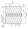
一実施形態は,流体デバイスを提供するものである。この流体デバイスは,互いに逆向きの第1及び第2本体部を有するマニホルド体を備える。第1本体部は,ポートアレーを形成する受けポートを有する。ポートアレーは,第1本体部に沿って反応領域を画定する。第2本体部は,流体デバイスが試料基板上にマウントされたときに反応チャンバを形成する開放凹部を有する。反応チャンバは,流体供給領域を画定するチャンバアレーを形成する。反応領域は,流体供給領域よりも大きい。マニホルド体は,該マニホルド体の外部に向けて開放するベント開口を含む。流体デバイスは,マニホルド体を貫通する上流側チャネルを更に備える。上流側チャネルの各々は,ポートアレーにおいて対応する受けポートを,チャンバアレーにおいて対応する反応チャンバに流体接続する。流体デバイスは,マニホルド体を貫通するベントチャネルを更に備える。ベントチャネルの各々は,チャンバアレーにおいて対応する反応チャンバを対応するベント開口に流体接続する。 One embodiment provides a fluidic device. The fluid device includes a manifold body having first and second body portions that are opposite to each other. The first body has a receiving port forming a port array. The port array defines a reaction area along the first body. The second body has an open recess forming a reaction chamber when the fluid device is mounted on the sample substrate. The reaction chamber forms a chamber array that defines a fluid supply area. The reaction area is larger than the fluid supply area. The manifold body includes a vent opening that opens to the outside of the manifold body. The fluidic device further comprises an upstream channel extending through the manifold body. Each of the upstream channels fluidly connects a corresponding receiving port in the port array to a corresponding reaction chamber in the chamber array. The fluidic device further comprises a vent channel extending through the manifold body. Each of the vent channels fluidly connects a corresponding reaction chamber in a chamber array to a corresponding vent opening.
一実施形態は,試料基板の調製方法を提供するものである。この調製方法は,基板面と,反応サイトのサイトアレーとを有する基板を準備するステップを備える。調製方法は,基板上に流体デバイスをマウントするステップを更に含む。この流体デバイスは,互いに逆向きの第1及び第2本体部を有するマニホルド体を含む。第1本体部は,ポートアレーを形成する受けポートを有する。第2本体部は,該第2本体部が試料基板上にマウントされたときに反応チャンバを形成する開放凹部を有する。マニホルド体は,該マニホルド体の外部に向けて開放するベント開口を有する。マニホルド体は,これを貫通する上流側チャネル及びベントチャネルを備える。上流側チャネルの各々は,ポートアレーにおいて対応する受けポートを,チャンバアレーにおいて対応する反応チャンバに流体接続する。ベントチャネルの各々は,チャンバアレーにおいて対応する反応チャンバを対応するベント開口に流体接続する。調製方法は,流体を前記受けポート経由で前記対応する反応チャンバまで流通させるステップを更に備える。サイトアレーの周囲長さは,流体をサイトアレーに向けて収束させるように,ポートアレーの周囲長さよりも短いものとし,ベントチャネルは,反応チャンバから排出されたガス,又は前記反応チャンバからの流体の少なくとも一方を受け入れる。 One embodiment provides a method for preparing a sample substrate. The method includes providing a substrate having a substrate surface and a site array of reaction sites. The preparation method further includes mounting the fluidic device on the substrate. The fluid device includes a manifold body having first and second body portions that are opposite to each other. The first body has a receiving port forming a port array. The second body has an open recess forming a reaction chamber when the second body is mounted on the sample substrate. The manifold body has a vent opening that opens to the outside of the manifold body. The manifold body has an upstream channel and a vent channel therethrough. Each of the upstream channels fluidly connects a corresponding receiving port in the port array to a corresponding reaction chamber in the chamber array. Each of the vent channels fluidly connects a corresponding reaction chamber in a chamber array to a corresponding vent opening. The method further comprises the step of flowing a fluid through the receiving port to the corresponding reaction chamber. The perimeter of the sight array shall be less than the perimeter of the port array so that the fluid converges towards the sight array, and the vent channel shall be the gas discharged from the reaction chamber or the fluid from the reaction chamber. Accept at least one of
一実施形態は,流体デバイスを提供するものである。この流体デバイスは,外側部と,反対側の内側部と,前記外側部に沿って配置される受けポートのポートアレーとを有する入口層を備える。入口層は,内側部に沿って延在するチャネルセグメントを含む。入口層は,外側部に沿って延在するベントポートを更に含む。流体デバイスは,貫通孔を有するユニオン層と,反応チャンバを有するチャンバ層とを更に備える。入口層,ユニオン層及びチャンバ層は,並行して積み重ねられる。ユニオン層は,入口層及びチャンバ層の間に配置される。マニホルド体は複数の流路チャネルを含み,該流路チャネルの各々は,互いに流体接続された受けポート,チャネルセグメント,開放凹部,貫通孔,及びベントポートを含む。任意的に,各流路チャネルは略共通の容積を有する。 One embodiment provides a fluidic device. The fluidic device includes an inlet layer having an outer portion, an opposite inner portion, and a port array of receiving ports disposed along the outer portion. The inlet layer includes a channel segment extending along the inside. The inlet layer further includes a vent port extending along the outer portion. The fluid device further includes a union layer having a through hole and a chamber layer having a reaction chamber. The inlet layer, union layer and chamber layer are stacked in parallel. The union layer is located between the inlet layer and the chamber layer. The manifold body includes a plurality of flow channels, each of the flow channels including a receiving port, a channel segment, an open recess, a through hole, and a vent port fluidly connected to each other. Optionally, each flow channel has a substantially common volume.
一実施形態は,流体デバイスを提供するものである。この流体デバイスは,互いに逆向きの第1及び第2本体部を有するマニホルド体を備える。第1本体部は,ポートアレーを形成する受けポートを有する。ポートアレーは,第1本体部に沿う反応領域を画定する。第2本体部は,流体デバイスが試料基板上にマウントされたときに反応チャンバを形成する開放凹部を有する。反応チャンバは,流体供給領域を画定するチャンバアレーを形成する。反応領域は,流体供給領域よりも大きい。マニホルド体は,該マニホルド体の外部に向けて開放する出口開口を含む。流体デバイスは,マニホルド体を貫通する上流側チャネルを備える。上流側チャネルの各々は,ポートアレーにおいて対応する受けポートを,チャンバアレーにおいて対応する反応チャンバに流体接続する。流体デバイスは,マニホルド体を貫通する下流側チャネルを更に備える。下流側チャネルの各々は,チャンバアレーにおいて対応する反応チャンバを,対応する出口開口に流体接続する。 One embodiment provides a fluidic device. The fluid device includes a manifold body having first and second body portions that are opposite to each other. The first body has a receiving port forming a port array. The port array defines a reaction area along the first body. The second body has an open recess forming a reaction chamber when the fluid device is mounted on the sample substrate. The reaction chamber forms a chamber array that defines a fluid supply area. The reaction area is larger than the fluid supply area. The manifold body includes an outlet opening that opens to the outside of the manifold body. The fluidic device includes an upstream channel through the manifold body. Each of the upstream channels fluidly connects a corresponding receiving port in the port array to a corresponding reaction chamber in the chamber array. The fluidic device further comprises a downstream channel extending through the manifold body. Each of the downstream channels fluidly connects a corresponding reaction chamber in a chamber array to a corresponding outlet opening.
一実施形態は,流体デバイスを提供するものである。この流体デバイスは,互いに逆向きの第1及び第2本体部と,該第1及び第2本体部の間に延在してこれらを結合する本体縁部とを有するマニホルド体を備える。本体縁部は,ポートアレーを形成する受けポートを有する。第2本体部は,流体デバイスが試料基板上にマウントされたときに反応チャンバを形成する開放凹部を有する。チャンバアレーの面積は,ポートアレーの面積よりも小さい。マニホルド体は,該マニホルド体の外部に向けて開放するベント開口を含む。流体デバイスは,マニホルド体を貫通する上流側チャネルを更に備える。上流側チャネルの各々は,ポートアレーにおいて対応する受けポートを,チャンバアレーにおいて対応する反応チャンバに流体接続する。流体デバイスは,マニホルド体を貫通するベントチャネルを更に備える。ベントチャネルの各々は,チャンバアレーにおいて対応する反応チャンバを,対応するベント開口に流体接続する。 One embodiment provides a fluidic device. The fluidic device includes a manifold body having first and second body portions that are opposite to each other, and a body edge extending between and connecting the first and second body portions. The body edge has a receiving port forming a port array. The second body has an open recess forming a reaction chamber when the fluid device is mounted on the sample substrate. The area of the chamber array is smaller than the area of the port array. The manifold body includes a vent opening that opens to the outside of the manifold body. The fluidic device further comprises an upstream channel extending through the manifold body. Each of the upstream channels fluidly connects a corresponding receiving port in the port array to a corresponding reaction chamber in the chamber array. The fluidic device further comprises a vent channel extending through the manifold body. Each of the vent channels fluidly connects a corresponding reaction chamber in a chamber array to a corresponding vent opening.
本発明の実施形態は,指定された反応を行わせるための試料支持体及び分析システムを含む。特定の実施形態において,試料支持体又は分析システムは,1種又は2種以上の生物学的又は化学的試料が配置される表面を有する試料基板を保持する。試料支持体及び分析システムは,1種又は2種以上の流体(例えば,液体や気体)が基板表面に沿って流れる際に基板を保持する。本発明の実施形態は,試料支持体と相互作用する装置,例えばシステムラックやその他の分析装置も含む。本発明の実施形態は,試料支持体を組み立て,使用する方法も含む。本発明の実施形態は,既知の装置,システム及び方法と対比して,指定されたプロトコルを実行するための時間を短縮することができ,及び/又はユーザフレンドリーな構成とし得るものである。 Embodiments of the present invention include a sample support and an analysis system for performing a specified reaction. In certain embodiments, a sample support or analysis system holds a sample substrate having a surface on which one or more biological or chemical samples are located. The sample support and the analysis system hold the substrate as one or more fluids (eg, liquids and gases) flow along the substrate surface. Embodiments of the present invention also include devices that interact with the sample support, such as a system rack or other analytical device. Embodiments of the present invention also include a method of assembling and using a sample support. Embodiments of the present invention may reduce the time to execute a specified protocol and / or may be user-friendly in comparison to known devices, systems and methods.
本明細書において,「試料支持体」という用語は,指定された分析プロトコルの間,1種又は2種以上の試料を1つ又は複数の反応チャンバ内に保持することのできるデバイスまたは装置を含む。特定の実施形態において,試料支持体は,複数の独立した反応チャンバを含むことができる。試料支持体は,反応チャンバ内における温度を制御可能な温度制御ブロックを備えることができる。例えば,温度制御ブロックは,反応チャンバの一部に近接し,又は該一部を画定する指定エリアを含むことができる。温度制御ブロックは,反応チャンバへの熱,及び/又は反応チャンバからの熱を,指定されたエリアを通して伝達し得る構成とすることができる。そのために,温度制御ブロックは,反応チャンバ内の温度を制御するのに適した熱伝達材料で構成される。一実施形態において,温度制御ブロックはチャネルを備えることができる。任意的に,チャネルは,熱エネルギを伝達するためのヒートパイプを備えることができる。 As used herein, the term "sample support" includes a device or apparatus capable of holding one or more samples in one or more reaction chambers during a specified analysis protocol. . In certain embodiments, a sample support can include a plurality of independent reaction chambers. The sample support may include a temperature control block capable of controlling the temperature in the reaction chamber. For example, the temperature control block can include a designated area proximate to or defining a portion of the reaction chamber. The temperature control block can be configured to transfer heat to and / or from the reaction chamber through a designated area. To this end, the temperature control block is made of a heat transfer material suitable for controlling the temperature in the reaction chamber. In one embodiment, the temperature control block can include a channel. Optionally, the channel can include a heat pipe for transferring thermal energy.
試料支持体は,反応チャンバを形成するための1つ又は複数のチャンバセルを含むことができる。本明細書において,「チャンバセル」という用語は,チャンバセルを含む物体,又は他の構成要素と組み合わされたときにチャンバセルを形成する物体を含む。非限定的な例としては,スライド,チップ,フローセル,キュベット等が含まれる。一実施形態において,チャンバセルの主要な機能は,反応チャンバの全部または一部を画定することである。チャンバセルは,指定された反応を行わせるに適して1種又は2種以上の材料で構成することができる。例えば,チャンバセルは,反応チャンバの形成を容易とするように指定された形状を有するガラスセル又はプラスチックセルで構成することができる。その材料は,指定された反応に関して不活性とすることができる。ある場合には,チャンバセルは,実質的に単一の材料(例えば,ガラス又はプラスチック)から製造される。任意的に,チャンバセルは,化学的に改質された表面を有することができる。例えば,チャンバセルの表面は,試料のチャンバセルに対する固定化を容易とするように機能化された構成とすることができる。任意的に,チャンバセルは,光学的透明材料を含み,これを通して検出のために光学信号を発生可能とする。 The sample support can include one or more chamber cells for forming a reaction chamber. As used herein, the term "chamber cell" includes an object that includes a chamber cell or that, when combined with other components, forms a chamber cell. Non-limiting examples include slides, chips, flow cells, cuvettes, and the like. In one embodiment, the primary function of the chamber cell is to define all or part of the reaction chamber. The chamber cell can be composed of one or more materials suitable for performing a specified reaction. For example, the chamber cell can be comprised of a glass cell or a plastic cell having a shape specified to facilitate the formation of a reaction chamber. The material can be inert with respect to the specified reaction. In some cases, the chamber cells are manufactured from a substantially single material (eg, glass or plastic). Optionally, the chamber cell can have a chemically modified surface. For example, the surface of the chamber cell can be configured to be functionalized so that the sample can be easily fixed to the chamber cell. Optionally, the chamber cell includes an optically transparent material through which optical signals can be generated for detection.
チャンバセルは,温度制御ブロックに対して離散的な構成要素であり,温度制御ブロックから分離又は除去可能である。一実施形態においては,単一のチャンバセルが単一の反応チャンバを形成するように構成されている。他の実施形態においては,単一のチャンバセルが複数の反応チャンバを形成するように構成されている。温度制御ブロック及びチャンバセルは,複数回使用ができる構成とすることができる。他の実施形態において,温度制御ブロック及びチャンバセルは,一回使用部品(例えば,使い捨て部品)として構成することができる。一実施形態において,試料支持体は,一体構造として組み合わされる複数の離散的な部品を有する。特に,試料支持体は,ユニットとして搬送され,かつ,分析装置内に配置される構成とすることができる。 The chamber cell is a discrete component to the temperature control block and can be separated or removed from the temperature control block. In one embodiment, a single chamber cell is configured to form a single reaction chamber. In another embodiment, a single chamber cell is configured to form multiple reaction chambers. The temperature control block and the chamber cell can be configured to be used multiple times. In other embodiments, the temperature control block and the chamber cell can be configured as a single use component (eg, a disposable component). In one embodiment, the sample support has a plurality of discrete components that are combined as a unitary structure. In particular, the sample support can be transported as a unit and arranged in the analyzer.
本明細書において,「反応チャンバ」という用語は,試料を配置することができ,流体を流すことにより指定された反応を行わせるスペース又はボイドを含む。反応チャンバは,典型的には少なくとも1つのポートを含む。特定の実施形態において,反応チャンバは,典型的には少なくとも1つの入口ポートと,少なくとも1つの出口ポートを含む。図示の実施形態において,各反応チャンバは,単一の入口ポートと,単一の出口ポートを含む。しかしながら,他の実施形態において,反応チャンバは,単一の入口ポートと,複数の出口ポートを含むことができる。代替的に,反応チャンバは,複数の入口ポートと,単一の出口ポートを含むことができる。更に他の実施形態において,反応チャンバは,流体が流入し,かつ流出する単一のポートを含むことができる。一実施形態において,反応チャンバは,一様な寸法を有する単純な流れチャネルである。例えば,反応チャンバは,互いに行に延在する2つの平面の間に画定することができる。他の実施形態において,反応チャンバの寸法は変化することができる。例えば,反応チャンバは,1つの平面と,ウェル,ピット又は溝を有する他の平面との間に画定することができる。 As used herein, the term "reaction chamber" includes a space or void in which a sample can be placed and in which the flow of a fluid causes a specified reaction to take place. The reaction chamber typically includes at least one port. In certain embodiments, the reaction chamber typically includes at least one inlet port and at least one outlet port. In the illustrated embodiment, each reaction chamber includes a single inlet port and a single outlet port. However, in other embodiments, the reaction chamber can include a single inlet port and multiple outlet ports. Alternatively, the reaction chamber can include multiple inlet ports and a single outlet port. In still other embodiments, the reaction chamber can include a single port for fluid inflow and outflow. In one embodiment, the reaction chamber is a simple flow channel having uniform dimensions. For example, a reaction chamber can be defined between two planes extending in rows with each other. In other embodiments, the dimensions of the reaction chamber can vary. For example, a reaction chamber can be defined between one plane and another plane having wells, pits or grooves.
本明細書において,「分析プロトコル」という用語は,指定された反応を行わせ,指定された反応を検出し,及び/又は指定された反応を分析するための一連の操作を含む。分析プロトコルにおける操作は,流体操作,熱的制御操作,検出操作,及び/又は機械的操作を含む。流体操作は,試料支持体又は分析システムを通しての流体(例えば,液体や気体)の流れ制御を含む。例えば,流体操作は,生物学的試料又は反応成分の反応チャンバへの流れを誘発するためのポンプ制御を含むことができる。熱的制御操作は,試料支持体又は分析システムにおける指定された部分の温度制御を含むことができる。例えば,熱的制御操作は,特定の反応を容易とするために,反応チャンバの温度を上昇又は降下させることを含み得る。検出操作は,試料における特定の特性,特質又は特徴を検出するための検出器の作動制御,又は検出器の活動モニタリングを含むことができる。一例として,検出操作は,生物学的試料を含む指定エリアの撮像を行って,指定エリアからの蛍光発光を検出することを含み得る。検出操作は,生物学的試料を照射するための光源制御を含み得る。機械的操作は,指定された部品の移動または位置制御を含むことができる。例えば,機械的操作は,分析システムのおけるロボットアームを移動させるためのモータ制御を含むことができる。ある場合には,異なる操作の組み合わせを同時に生じさせることができる。 As used herein, the term "analytical protocol" includes a series of operations for causing a specified reaction to occur, detecting the specified reaction, and / or analyzing the specified reaction. The operations in the analysis protocol include fluid operations, thermal control operations, detection operations, and / or mechanical operations. Fluid manipulation involves controlling the flow of a fluid (eg, liquid or gas) through a sample support or analysis system. For example, fluidic operation can include pump control to induce a flow of a biological sample or reaction component into a reaction chamber. Thermal control operations can include temperature control of a sample support or a designated portion of an analysis system. For example, thermal control operations can include increasing or decreasing the temperature of the reaction chamber to facilitate a particular reaction. The detecting operation can include controlling the operation of the detector to detect a particular property, characteristic or characteristic in the sample, or monitoring the activity of the detector. As an example, the detection operation may include taking an image of a designated area containing the biological sample and detecting fluorescence emission from the designated area. The detection operation may include light source control for illuminating the biological sample. Mechanical operations can include movement or position control of specified parts. For example, mechanical operation can include motor control to move a robot arm in an analysis system. In some cases, different combinations of operations can occur simultaneously.
本発明の実施形態において実行可能なプロトコルには,マルチプレックスアレー分析が含まれる。ある種のマルチプレックスアレー分析プロトコルにおいては,異なるプローブ分子の集団が基板表面上に固定される。プローブは,支持体表面上における各プローブのアドレスに基づいて区別することができる。例えば,プローブ分子の各集団は,支持体表面上における既知の場所(例えば,格子上の座標)を有することがある。プローブ分子を制御された条件下で目標分析物にさらすと,目標分析物とプローブとの相互作用により,1つ又は複数のアドレスにおいて検出可能な変化が生じる。目標分析物は,目標分析物と選択的に結合する1種又は2種以上の蛍光ラベルを含むか,又は該蛍光ラベルに後続的にさらすことができる。次に,蛍光ラベルを励起し,これからの発光を検出することにより,目標分析物を分析することができる。特定のプローブと結合する目標分析物は,プローブのアドレスに対する蛍光ラベルの漸増により特定可能である。アレーのアドレスは,どの集団が分析物と反応したかを特定する分析システムにより決定することができる。分析物と反応したプローブ分子の化学構造を知ることにより,分析物の特性を決定することができる。 Protocols that can be implemented in embodiments of the present invention include multiplex array analysis. In some multiplex array analysis protocols, different populations of probe molecules are immobilized on the substrate surface. Probes can be distinguished based on the address of each probe on the support surface. For example, each population of probe molecules may have a known location on the support surface (eg, coordinates on a grid). Exposure of the probe molecule to the target analyte under controlled conditions results in a detectable change in one or more addresses due to the interaction of the target analyte with the probe. The target analyte may include or be subsequently exposed to one or more fluorescent labels that selectively bind to the target analyte. The target analyte can then be analyzed by exciting the fluorescent label and detecting the emission from it. The target analyte that binds to a particular probe can be identified by increasing the fluorescent label to the address of the probe. The address of the array can be determined by an analysis system that identifies which population has reacted with the analyte. By knowing the chemical structure of the probe molecule that has reacted with the analyte, the properties of the analyte can be determined.
本明細書において,「試料」という用語は,例えば,制御された反応を通じて改質可能な物質,又は,ここに記載されるような反応チャンバ内で検出可能な物質を含む。特定の実施形態において,試料は,関心対象となる生物学的又は化学的物質を含むことができる。本明細書において,「生物学的物質」又は「化学的物質」という用語は,観察(例えば,撮像)を行い,又は検査するのに適した各種の生物学的又は化学的物質を含むことができる。例えば,生物学的又は化学的物質は,生体分子,ヌクレオシド,核酸,ポリヌクレオチド,オリゴヌクレオチド,タンパク質,酵素,ポリペプチド,抗体,抗原,リガンド,レセプター,多糖,炭水化物,ポリリン酸,ナノ細孔,細胞小器官,脂質層,細胞,細胞溶解物,組織,器官,生体,体液を含む。「生物学的又は化学的試料」という用語は,生物学的活性のある化学物質,例えば上述した種の類似又は擬態を含むことができる。「生物学的試料」という用語は,細胞溶解物,無傷の細胞,生体,器官,組織及び体液等の試料を含む。「体液」は,限定されるものではないが,血液,乾燥血液,凝固した血液,血清,血漿,唾液,脳脊髄液,胸水,涙,ラクタールダクトの流体,リンパ液,痰,尿,羊水及び精液を含む。試料は,「無細胞」の体液を含むことができる。「無細胞体液」は,約1%(w/w)未満の全体細胞物質を含む。血清及び血漿は,無細胞体液の例である。試料は,天然又は合成由来の検体を含むことができる。一実施形態において,生物学的試料はヒト由来の,又はヒト以外に由来するものとすることができる。一実施形態において,生物学的試料は,ヒト患者由来とすることができる。一実施形態において,生物学的試料は,新生児由来とすることができる。 As used herein, the term "sample" includes a substance that can be modified, for example, through a controlled reaction, or a substance that can be detected in a reaction chamber as described herein. In certain embodiments, the sample can include a biological or chemical substance of interest. As used herein, the term "biological substance" or "chemical substance" may include various biological or chemical substances that are suitable for making or examining (eg, imaging). it can. For example, biological or chemical substances include biomolecules, nucleosides, nucleic acids, polynucleotides, oligonucleotides, proteins, enzymes, polypeptides, antibodies, antigens, ligands, receptors, polysaccharides, carbohydrates, polyphosphates, nanopores, Includes organelles, lipid layers, cells, cell lysates, tissues, organs, organisms, and body fluids. The term "biological or chemical sample" can include a biologically active chemical, such as a similar or mimic of the species described above. The term "biological sample" includes samples such as cell lysates, intact cells, organisms, organs, tissues and fluids. "Body fluids" include, but are not limited to, blood, dried blood, coagulated blood, serum, plasma, saliva, cerebrospinal fluid, pleural effusion, tears, lactal duct fluid, lymph, sputum, urine, amniotic fluid and Including semen. The sample can include "cell-free" bodily fluids. "Cell-free fluid" contains less than about 1% (w / w) of total cellular material. Serum and plasma are examples of cell-free body fluids. The sample can include analytes of natural or synthetic origin. In one embodiment, the biological sample can be of human or non-human origin. In one embodiment, the biological sample can be from a human patient. In one embodiment, the biological sample can be from a newborn.
特定の実施形態において,試料は基板又は支持構造における1つ又は複数の表面に固定することができる。例えば,オープンフェース基板(例えば,ある種のマイクロアレー及びチップ等)では,生物学的又は化学的試料がオープンフェース基板の外面に固定される。チャンバセルは,例えば生物学的又は化学的物質が固定される反応チャンバ又は流路を画定することができる。生物学的又は化学的物質は,チャンバセルの表面及び/又は反応チャンバ内における試料基板の表面に固定することができる。試料基板は,1つ又は複数のスライド,オープンフェース基板,プレーナチップ(例えば,マイクロアレーにおいて使用されるもの),又は微細粒子を含むことができる。光学基板が,生物学的又は化学的物質を支持する複数の微細粒子を含む場合,微細粒子は他の光学基板,例えばスライド,ピットアレー又は溝付きプレートにより保持することができる。 In certain embodiments, the sample can be fixed to one or more surfaces on a substrate or support structure. For example, in an open face substrate (eg, certain microarrays and chips, etc.), a biological or chemical sample is immobilized on the outer surface of the open face substrate. A chamber cell can define, for example, a reaction chamber or flow path in which biological or chemical substances are immobilized. Biological or chemical substances can be immobilized on the surface of the chamber cell and / or on the surface of the sample substrate in the reaction chamber. The sample substrate can include one or more slides, open face substrates, planar chips (eg, those used in microarrays), or fine particles. If the optical substrate comprises a plurality of microparticles supporting a biological or chemical substance, the microparticles can be held by another optical substrate, for example a slide, a pit array or a grooved plate.
特定の実施形態において,試料基板はマイクロアレーを含む。マイクロアレーは,基板表面に固定される,異なるプローブ分子の集団を含むことができる。この場合,異なるプローブ分子はその相対位置によって互いに区別される。マイクロアレーは,基板上における異なるアクセル可能位置に固定された異なるプローブ分子,又はプローブ分子の集団を含むことができる。代替的に,マイクロアレーは,各々が異なるプローブ分子,又はプローブ分子の集団を支持する別個の光学基板,例えばビードを含むことができる。この場合に,異なるプローブ分子は,基板を固定した表面上における光学基板の位置に基づいて,又は液体中における基板の位置に基づいて互いに区別される。表面上に別個の基板が配置されるアレーには,非限定的な意味において,以下に例示するものが含まれる。即ち,Illumina Inc.(米国カリフォルニア州サンディエゴ所在)から入手可能なBeadChipアレー,並びに,ビードをウェル内に含むアレー,例えば米国特許第6,266,459号,同第6,355,431号,同第6,770,441号,同第6,859,570号,同第7,622,294号及び国際公開第00/63437号各明細書に開示されているアレーや,表面上に粒子を有するアレー,例えば米国特許出願公開第2005/0227252号,国際公開第05/033681号及び同第04/024328号各明細書に開示されているアレーである。これらの特許文献は,参照として本願に組み込まれる。 In certain embodiments, the sample substrate includes a microarray. Microarrays can include different populations of probe molecules that are immobilized on a substrate surface. In this case, different probe molecules are distinguished from each other by their relative positions. The microarray can include different probe molecules, or populations of probe molecules, fixed at different accessible positions on the substrate. Alternatively, the microarray can include separate optical substrates, eg, beads, each supporting a different probe molecule, or population of probe molecules. In this case, the different probe molecules are distinguished from each other based on the position of the optical substrate on the surface to which the substrate is fixed or on the position of the substrate in the liquid. Arrays in which separate substrates are disposed on a surface include, in a non-limiting sense, those exemplified below. A BeadChip array available from Illumina Inc. (San Diego, Calif., USA) and an array containing beads in a well, such as US Pat. Nos. 6,266,459, 6,355,431, 6,770,441, and 6,859,570. No. 7,622,294 and WO 00/63437, and arrays having particles on the surface, such as US Patent Application Publication No. 2005/0227252, WO 05/033681. And the arrays disclosed in the specifications of Japanese Patent Application No. 04/024328. These patent documents are incorporated herein by reference.
当業界において既知である任意の各種マイクロアレーを使用することができる。典型的なマイクロアレーは,各々がプローブ集団を有する反応サイト(「特徴」とも称される)を含む。各反応サイトにおけるプローブ集団は,典型的には1種のプローブを有する同種集団であるが,一実施形態においては異種集団とすることもできる。アレーにおける反応サイト又は特徴は,典型的には離散的であり,互いに間隔をおいて離間する。プローブサイトの寸法,及び/又は反応サイトの間隔は,アレーが高密度,中密度又は低密度となるように変化させることができる。高密度アレーは,約15 μmの間隔で離間する反応サイトを有するものとして特徴づけられる。中密度アレーは約15〜30 μmの間隔で離間する反応サイトを有し,低高密度アレーは,30 μmを超える間隔で離間する反応サイトを有する。本発明において有用なアレーは,100 μm,50 μm,10 μm,5 μm,1 μm又は0.5 μmの間隔で離間する反応サイトを有する。本発明の一実施形態に係る装置又は方法は,サイトを撮像するために使用することができ,その場合の解像度は,上記の密度又は密度範囲においてサイトを区別するに十分なものである。 Any of a variety of microarrays known in the art can be used. A typical microarray includes reaction sites (also called "features") each having a population of probes. The probe population at each reaction site is typically a homogenous population with one probe, but can be a heterogeneous population in one embodiment. The reaction sites or features in the array are typically discrete and spaced apart from each other. The size of the probe sites and / or the spacing of the reaction sites can be varied so that the array is dense, medium or low density. High-density arrays are characterized as having reaction sites spaced about 15 μm apart. Medium-density arrays have reaction sites spaced about 15 to 30 μm apart, and low-density arrays have reaction sites spaced more than 30 μm apart. Arrays useful in the present invention have reaction sites spaced at intervals of 100 μm, 50 μm, 10 μm, 5 μm, 1 μm or 0.5 μm. An apparatus or method according to an embodiment of the present invention can be used to image sites, where the resolution is sufficient to distinguish sites in the above densities or density ranges.
本発明で使用可能であって,商業的に入手可能なマイクロアレーの更なる例には,Affymetrix(登録商標)GeneChip(登録商標)マイクロアレー,又はVLSIPS(Very Large Scale Immobilized Polymer Synthesis)とも称される技術に基づいて合成された他のマイクロアレーが含まれる。VLSIPS法については,例えば,米国特許第5,324,633号,同第5,744,305号,同第5,451,683号,同第5,482,867号,同第5,491,074号,同第5,624,711号,同第5,795,716号,同第5,831,070号,同第5,856,101号,同第5,858,659号,同第5,874,219号,同第5,968,740号,同第5,974,164号,同第5,981,185号,同第5,981,956号,同第6,025,601号,同第6,033,860号,同第6,090,555号,同第6,136,269号,同第6,022,963号,同第6,083,697号,同第6,291,183号,同第6,309,831号,同第6,416,949号,同第6,428,752号及び同第6,482,591号各明細書に記載されている。これらの特許文献は,参照として本願に組み込まれる。スポット型マイクロアレーは,例えば,Amersham(登録商標)Biosciences社から入手可能なCodeLink(商標)アレーである。他の有用なマイクロアレーは,SurePrint(登録商標)等のインクジェット印刷法を使用して再象されるマイクロアレーであり,Agilent(登録商標)Technologies社から入手可能である。既知の分析法の何れも,例えば,米国特許出願公開第2003/0108867号,同第2003/0108900号,同第2003/0170684号,同第2003/0207295号又は同第2005/0181394号各明細書に記載されているマイクロアレーを使用して,ターゲットを特定し,又は特徴づけるために使用することができる。これらの特許文献も,参照として本願に組み込まれる。 Further examples of commercially available microarrays that can be used in the present invention are Affymetrix® GeneChip® microarrays, or VLSIPS (Very Large Scale Immobilized Polymer Synthesis). Other microarrays synthesized based on such techniques are included. Regarding the VLSIPS method, for example, US Patent Nos. 5,324,633, 5,744,305, 5,451,683, 5,482,867, 5,491,074, 5,624,711, 5,795,716, 5,831,070, 5,831,070 No. 5,856,101, No. 5,858,659, No. 5,874,219, No. 5,968,740, No. 5,974,164, No. 5,981,185, No. 5,981,956, No. 6,025,601, No. 6,033,860, No. 6,090,555, No. Nos. 6,136,269, 6,022,963, 6,083,697, 6,291,183, 6,309,831, 6,416,949, 6,428,752, and 6,482,591. These patent documents are incorporated herein by reference. The spot-type microarray is, for example, a CodeLink ™ array available from Amersham® Biosciences. Another useful microarray is a microarray that is recreated using an inkjet printing method such as SurePrint®, and is available from Agilent® Technologies. Any of the known analytical methods are described, for example, in U.S. Patent Application Publication Nos. 2003/0108867, 2003/0108900, 2003/0170684, 2003/0207295, and 2005/0181394. Can be used to identify or characterize a target. These patent documents are also incorporated herein by reference.
一実施形態において,ここに開示する実施形態は核酸のシーケンシングのために使用することができる。例えば,Sequencing by Synthesis(SBS)プロトコルは,特に適用可能である。SBS法では,蛍光ラベルされた複数の修正ヌクレオチドを使用して,光学基板の表面(例えばチャンバセル内の流路を少なく十部分的に画定する表面)に存在する増幅DNAの高密度クラスター(数百万のクラスターであり得る)のシーケンスを行う。チャンバセルは,チャンバセルが適切なチャンバセルホルダ内に配置された場所においてシーケンス用の核酸試料を収めることができる。シーケンシング用の試料は,互いに分離させて個別的に解像可能とした単一核酸分子形態,クラスター又は他の特徴としての核酸分子の増幅集団形態,又は1つ又は複数の核酸分子に固定したビード形態とすることができる。核酸は,未知のターゲットシーケンスに近接するオリゴヌクレチドプライマーが含まれるように調製することができる。最初のSBSシーケンスサイクルを開始するため,1種又は2種以上の異なるラベルの施されたヌクレオチドと,DNAポリメラーゼ等を,流体流動サブシステム(図示せず)により,チャンバセル内に,又はチャンバセルを通じて流すことができる。単一種のヌクレオチドを一時に加えることができ,あるいは,シーケンス手順において使用されるヌクレオチドを,反転可能なターミネータ特性を有するように特別設計し,これにより,数種のラベルが施されたヌクレオチド(例えば,A,C,T,G)の存在下において,シーケンス反応の各サイクルを同時に発生可能とすることができる。ヌクレオチドは,検出可能なラベル成分,例えば蛍光団を含むことができる。4種のヌクレオチドが混合される場合,ポリメラーゼは組み込むべき正しいベースを選択することができ,各シーケンスは単一ベースによって拡張される。組み込まれないヌクレオチドは,チャンバセルを通して洗浄液を流すことにより,洗い流すことができる。1つ又は複数のレーザによりヌクレオチドを励起して,蛍光を誘発させることができる。核酸から発せられる蛍光は,組み込まれたベースの蛍光に基づくものであり,異なる蛍光は異なる波長の発光を生じさせる。デブロッキング試薬をチャンバセルに加えて,反転可能なターミネータ集団を,延長され,かつ検出されたDNAストランドから除去することができる。続いて,チャンバセルを通じて洗浄剤を流すことにより,デブロッキング試薬を洗い流すことができる。この状態で,チャンバセルは,上述した態様での,ラベルされたヌクレオチドの導入で始まる次のシーケンスサイクルの準備が整うこととなる。流動及び検出ステップを数回繰り返して,1回のシーケンスランを完了させることができる。シーケンス法は,例えば,Bentley et al., Nature 456:53-59 (2008),国際公開第04/018497号,同第91/06678号及び同第07/123,744号,米国特許第7,057,026号,同第7,329,492号,同第7,211,414号,同第7,315,019号及び同第7,405,281号,並びに米国特許出願公開第2008/0108082号各明細書に記載されている。これらの非特許文献及び特許文献も,参照として本願に組み込まれる。 In one embodiment, the embodiments disclosed herein can be used for nucleic acid sequencing. For example, the Sequencing by Synthesis (SBS) protocol is particularly applicable. In the SBS method, a plurality of modified nucleotides labeled with fluorescent light are used to form a high-density cluster (number) of amplified DNA on the surface of an optical substrate (for example, a surface that defines a flow path in a chamber cell at least partially). (Which could be one million clusters). The chamber cell can contain a nucleic acid sample for sequencing at a location where the chamber cell is located in a suitable chamber cell holder. The sample for sequencing may be in the form of a single nucleic acid molecule separated from each other and individually resolvable, an amplified population of nucleic acid molecules as clusters or other features, or immobilized on one or more nucleic acid molecules. It can be a bead form. Nucleic acids can be prepared to include oligonucleotide primers adjacent to an unknown target sequence. To initiate the first SBS sequence cycle, one or more differently labeled nucleotides and DNA polymerase, etc., are placed in a chamber cell or in a chamber cell by a fluid flow subsystem (not shown). Can be flowed through. A single type of nucleotide can be added at a time, or the nucleotides used in the sequencing procedure can be specially designed to have reversible terminator properties, such that several labeled nucleotides (eg, , A, C, T, G), each cycle of the sequence reaction can be simultaneously generated. The nucleotide can include a detectable label component, such as a fluorophore. When the four nucleotides are mixed, the polymerase can select the correct base to incorporate and each sequence is extended by a single base. Unincorporated nucleotides can be washed away by flushing the wash solution through the chamber cell. The nucleotides can be excited by one or more lasers to induce fluorescence. The fluorescence emitted from nucleic acids is based on the incorporated base fluorescence, with different fluorescences producing different wavelengths of emission. A deblocking reagent can be added to the chamber cell to remove the reversible terminator population from the extended and detected DNA strands. Subsequently, by flowing a cleaning agent through the chamber cell, the deblocking reagent can be washed away. In this state, the chamber cell is ready for the next sequence cycle starting with the introduction of the labeled nucleotide in the manner described above. The flow and detection steps can be repeated several times to complete one sequence run. The sequence method is described, for example, in Bentley et al., Nature 456: 53-59 (2008), WO 04/018497, WO 91/06678 and WO 07 / 123,744, US Patent Nos. 7,057,026, Nos. 7,329,492, 7,211,414, 7,315,019 and 7,405,281, and U.S. Patent Application Publication No. 2008/0108082. These non-patent and patent documents are also incorporated herein by reference.
一実施形態において,シーケンシングの間又はこれに先立って,核酸を表面に固定して増幅することができる。例えば,増幅はブリッジ増幅により行うことができる。有用なブリッジ増幅は,例えば,米国特許第5,641,658号及び同第7,115,400号,並びに同国特許出願公開第2002/0055100号,同第2004/0096853号,同第2004/0002090号,同第2007/0128624号及び同第2008/0009420号各明細書に記載されている。表面上の核酸を増幅するための他の有用な方法は,ローリングサークル増幅(RCA)であり,例えばLizardi et al., Nat. Genet. 19:225-232 (1998)及び米国特許出願公開第2007/0099208号明細書に記載されている。ビード上でのエマルジョンPCR法も使用することができ,これについてはDressman et al., Proc. Natl. Acad. Sci. USA 100:8817-8822 (2003) に記載されている。これらの非特許文献及び特許文献も,参照として本願に組み込まれる。 In one embodiment, the nucleic acids can be immobilized on a surface and amplified during or prior to sequencing. For example, amplification can be performed by bridge amplification. Useful bridge amplifications are described, for example, in U.S. Pat. And No. 2008/0009420. Another useful method for amplifying nucleic acids on a surface is rolling circle amplification (RCA), such as Lizardi et al., Nat. Genet. 19: 225-232 (1998) and US Patent Application Publication No. 2007/2007. / 0099208. Emulsion PCR on beads can also be used and is described in Dressman et al., Proc. Natl. Acad. Sci. USA 100: 8817-8822 (2003). These non-patent and patent documents are also incorporated herein by reference.
異なる素子及び部品は,着脱可能に結合することができる。本明細書において,2つ以上の素子及び部品が「着脱可能に結合」(又は「着脱可能に係合」)している場合,当該素子は,結合された部品を破壊することなく,互いに容易に取り外すことができる。部品を互いに分離するために過大な労力又は相当の時間を必要とせずに素子を互いに取り外すことができれば,素子は容易に着脱可能である。例えば,一実施形態において,試料支持体は,その生涯の間,システムラックに対して多数回に亘って着脱可能に結合させることができる。着脱可能に結合させると,試料支持体及びシステムラックは,1つ又は複数のプロトコルを実行するに最適な態様で作動させることができる。特定の実施形態において,素子は,機械又はシステムにより自動的に,着脱可能に結合させることができる。更に,一実施形態において,着脱可能に結合された素子は,結合された素子間で何らかの接触がなされる態様で,互いに直結することができる。他の実施形態において,着脱可能に結合された素子は,着脱可能な結合を容易とするための介在素子を有することができる。部品の着脱可能な結合の例示的なモードは,限定されるものではないが,摩擦係合(例えば,しまり嵌め,スナップ嵌め),磁力,真空,電荷,弱い接着剤又は機械的クランプ等で媒介される相互作用である。 Different elements and components can be removably coupled. As used herein, when two or more elements and components are "detachably coupled" (or "detachably engaged"), the components are easily connected to each other without destroying the coupled components. Can be removed. If the components can be removed from one another without undue effort or considerable time to separate the components from one another, the components are easily removable. For example, in one embodiment, the sample support may be detachably coupled to the system rack multiple times during its lifetime. When removably coupled, the sample support and system rack can be operated in a manner that is optimal for performing one or more protocols. In certain embodiments, the components can be removably coupled automatically by a machine or system. Further, in one embodiment, the removably coupled elements can be directly connected to each other in such a way that some contact is made between the coupled elements. In other embodiments, the removably coupled device can have intervening components to facilitate the releasable coupling. Exemplary modes of detachable coupling of components are not limited to, but are mediated by, for example, frictional engagement (eg, tight fit, snap fit), magnetic force, vacuum, electrical charge, weak adhesives, or mechanical clamps. Interaction.
他の実施形態において,異なる素子及び部品が容易に分離できない場合があり得る。例えば,サーモモジュールは,サーモモジュールが取付けられた温度制御ブロックから容易には分離できない場合があり得る。一実施形態において,試料支持体の部品は,互いに取付けられて一体ユニットを形成する離散的な部品であり得る。他の実施形態において,1つ又は複数の部品が他の部品から容易に分離できない場合があり得る。このように,本明細書において「(素子Aが素子B)に結合」という語句は,素子A及びBが,互いに着脱可能に結合された離散的な部品であること,又は,互いに結合されて容易には分離できない離散的な部品であること,又はその構造の一部であることを含むことがある。 In other embodiments, different elements and components may not be easily separable. For example, a thermo module may not be easily separable from a temperature control block to which the thermo module is attached. In one embodiment, the components of the sample support may be discrete components that are attached to one another to form an integral unit. In other embodiments, one or more components may not be easily separable from other components. Thus, in this specification, the phrase "(element A is coupled to element B)" means that elements A and B are discrete parts that are detachably coupled to each other, or that elements A and B are coupled to each other. It may include discrete parts that cannot be easily separated or are part of its structure.
本明細書において,「複数の(構成要素)」及び「(構成要素の)アレー」等の用語は,ある部品が有し得る全ての構成要素を必ずしも含むものではない。当該部品は,複数の構成要素と類似する他の構成要素を含むことができる。例えば,「(特定の特徴を構成し,又は特定の特徴を有する)複数のチャンバセル」という語句は,部品における全てのチャンバセルが特定の特徴を含むことを必ずしも意味しない。従って,(例えば「(特定の特徴を構成し,又は特定の特徴を有する)全てのチャンバセル」とでも特に明記しない限り,本発明の実施形態は,特定の特徴を有していない類似の構成要素を含む場合がある。 In this specification, terms such as "plurality of (components)" and "array of (components)" do not necessarily include all components that a part may have. The component can include other components that are similar to the plurality of components. For example, the phrase "a plurality of chamber cells (constituting or having a particular feature)" does not necessarily mean that all chamber cells in the part include the particular feature. Thus, unless otherwise specified (eg, "all chamber cells (constituting or having a particular feature)", embodiments of the present invention may be implemented in a similar configuration having no particular feature). May contain elements.
図1Aは,本発明の一実施形態に係る分析システム100の概略図である,図1Bは,分析システム100により使用可能な試料支持体102の線図的な正面図又は平面図である。分析システム100はシステムラック104を含む。システムラック104は,分析プロトコルの間に複数の試料支持体102を保持するように構成されている。分析プロトコルの間,試料基板(図示せず)に沿って配置された生物学的又は化学的試料は,調製し,及び/又は分析することができる。そのためには1種又は複数種の流体(例えば,液体や気体)を,反応チャンバを通して,そして生物学的又は化学的試料に沿って流す。例示として,分析プロトコルは,in−situハイブリダイゼーション(ISH),蛍光ISH(FISH),及び免疫組織化学染色(IHC)を含むことができる。しかしながら,各種の分析プロトコルを分析システム100により実行し得ることは,言うまでもない。図示の実施形態において,液体は,重力のみにより反応チャンバを通して排出することができる。しかしながら,他の実施形態において,例えば分析システム700(図27)において,空圧システムにより流体を,反応チャンバを通して強制排出することもできる。
FIG. 1A is a schematic diagram of an
図1Bを参照すれば,各試料支持体102は,温度制御ブロック106と,1つ又は複数のチャンバセル108とを含む。各チャンバセル108は,反応セル108内に,又はチャンバセル108と他の部品,例えば温度制御ブロック106,又は,チャンバセルがマウントされた試料基板(図示せず)との間に,反応チャンバ110を画定する。反応チャンバ110は,入口112と出口114との間に延在する。任意的に,試料支持体102は,サーモモジュール116,及び,温度制御ブロック106に取付けられた温度センサ118の少なくとも一方を含むことができる。サーモモジュール116は,反応チャンバ内における試料基板の温度を制御することができる。温度センサ118は,サーモモジュール116を制御するために使用可能な温度データを検出することができる。他の実施形態において,システムラック104は,温度センサ118及びサーモモジュール116の少なくとも一方を含むことができる。
Referring to FIG. 1B, each
分析システム100は,流体を試料支持体102に供給可能な流体制御システム120も含むことができる。流体制御システム120は,ストレージアセンブリ122と,供給サブシステム124と,廃液リザーバ126とを有することができる。ストレージアセンブリ122は,試薬,洗浄液,緩衝液等のための1つ又は複数の供給源128を含むことができ,これらの液体は,指定されたプロトコルを実行するために必要とされるものである。図示の実施形態において,供給サブシステム124は,1つ又は複数の,空圧制御される管路132(例えば,シリンジ)を有するロボットアーム130を含む。管路132は,液体を供給源128から吸引することができる。ロボットアーム130は,ストレージアセンブリ122から吸引された液体を試料支持体102に移送し,その液体を入口112に供給するように構成されている。例示的な実施形態において,入口112はトラフ形状とされている。液体を入口112に供給すると,液体を入口112内に貯めることができる。例示的な実施形態において,反応チャンバは,これを通して液体を,重力のみに基づいて流すことができる。他の実施形態において,反応チャンバを通じて1種又は複数種の液体を能動的にポンプで流すこともできる。
The
分析システム100における異なる部品の操作は,システムコントローラ142を有するコンピュータシステム140により制御することができる。システムコントローラ142は,マイクロプロセッサ型のシステムに基づく任意のプロセッサを含むことができ,これには,マイクロコントローラ,縮小命令セットコンピュータ(RISC),特定用途向け集積回路(ASIC),現場でプログラム可能なゲートアレイ(FPGA),論理回路,及び,本明細書に記載される機能を実行するために必要とされる他の回路やプロセッサを用いるシステムが含まれる。機能は,商業的に妥当な時間内で実行させることができる。上述した例は単なる例示に過ぎず,システムコントローラの定義及び/又は意味の限定を意図するものではない。例示的な実施形態において,システムコントローラ142は,検出データの取得及び分析の少なくとも一方のために,1つ又は複数のストレージ素子,メモリー,又はモジュールに保存されている命令セットを実行する。ストレージ素子は,分析システム100内における情報源又は物理的メモリー素子で構成することができる。一実施形態は,本明細書に記載される1つ又は複数のプロセスを実行するための命令セットが保存された,非一時的コンピュータ可読媒体を含む。非一時的コンピュータ可読媒体は,一時的伝播信号それ自体を除き,全てのコンピュータ可読媒体を含むことができる。非一時的コンピュータ可読媒体は,一般的には,有形物である任意のコンピュータ可読媒体を含み,これには,例えば,磁気及び/又は光学ディスク,ROM,PROM等の不揮発性メモリーや,RAM等の揮発性メモリーが含まれる。コンピュータ可読媒体は,1つ又は複数のプロセッサにより実行するための命令を保存することができる。
The operation of the different components in the
命令セットは,特定の操作,例えば分析プロトコルを実施するための方法及びプロセスの実行指令を分析システム100に与える命令を含むことができる。命令セットは,ソフトウェアプログラムで構成することができる。本明細書において,「ソフトウェア」及び「ファームウェア」という用語は互換性があり,コンピュータにより実行するためにメモリーに保存された任意のコンピュータプログラムをふくむ。そのメモリーには,RAMメモリー,ROMメモリー,EPROMメモリー,不揮発性RAM(NVRAM)が含まれる。上記のメモリー形式は単なる例示に過ぎず,コンピュータプログラムを保存するために使用可能なメモリー形式を限定するものではない。
The instruction set may include instructions that provide the
システムコントローラ142は,通信リンク(破線で示す)を介して分析システム100における他の部品又はシステムに接続することができる。システムコントローラ142は,オフサイトシステムやサーバに通信可能に接続することもできる。システムコントローラ142は,コンピュータシステム140のユーザインターフェースからのユーザ入力又は指令を受信することができる。このようなユーザ入力装置は,キーボード,マウス,タッチスクリーンパネル,及び/又は音声認識システム等を含むことができる。特定の実施形態において,システムコントローラ142は,サーモモジュール116(図1A)及び温度センサ118(図1A)に通信可能に接続される。
The
図2〜図26は,試料支持体やシステムラック等の各種実施形態を示す。ある特徴のみが特定の実施形態との関連で記載される場合があるが,それらの特徴が他の実施形態においても適用可能であることは,言うまでもない。例えば,試料支持体310(図7)は着脱カバー体320を含む。試料支持体670(図25)は,着脱カバー体を含むものとして図示されてはいないが,試料支持体670に着脱カバー体を含むように修正を加え得ることは,言うまでもない。他の例として,温度制御ブロック532(図18)には,整形特徴(例えば,成形特徴)を有する活性面542(図20)が設けられている。他の温度制御ブロックも類似又は同一の整形特徴を有し得ることは,言うまでもない。更に他の例として,温度制御ブロック402(図14)は,熱エネルギを伝達するためのチャネル452(図14)を含んでいる。他の温度制御ブロックが同様のチャネルを含み得ることは,言うまでもない。
2 to 26 show various embodiments such as a sample support and a system rack. Although only certain features may be described in connection with a particular embodiment, it will be understood that those features are applicable in other embodiments. For example, the sample support 310 (FIG. 7) includes a
図2は,本発明の一実施形態に係る試料支持体200の分解図である。試料支持体200は,試料支持体102(図1)を置換し得るものであり,分析システム100(図1)と共に作動するように構成されている。試料支持体200は複数の支持体部品を有し,これらには,伸長した温度制御ブロック202,光学セルスペーサ204,複数のチャンバセル206及び着脱カバー体208が含まれる。各支持体部品は,Z軸に沿って互いに積み重ね得るように構成されている。例えば,セルスペーサ204は,温度制御ブロック202上に配置することができる。他の実施形態において,試料支持体200は,セルスペーサを含まない構成とすることができる。この実施形態においては,セルスペーサの特徴を,温度制御ブロック202及び/又はチャンバセル206に組み込むことができる。
FIG. 2 is an exploded view of the
チャンバセル206をセルスペーサ204上,及び/又は温度制御ブロック202上に配置して,対応する反応チャンバ212(図3及び図6)を画定することができる。着脱カバー体208は,チャンバセル206上,セルスペーサ204上,及び/又は温度制御ブロック202上に配置することができる。着脱カバー体208を温度制御ブロック202に取付けて,チャンバセル208を,着脱カバー体208と温度制御ブロック202との間の指定された位置で保持可能とすることができる。図5に示す完全に組み立てられた状態において,試料支持体200は,複数の試料基板210が対応する反応チャンバ212(図3及び図6)内に配置され,指定された1つ又は複数の反応が行われるためのデバイスを提供する。
各試料支持体210は,互いに対向する第1及び第2本体表面216, 281を有する基板本体214を含む。試料支持体200の完全に組み立てられた状態において,第1本体表面216は,反応チャンバ212の一部を画定し,その上に指定された試料220を有することができる。本明細書において,「試料」という用語は,単一種の生物学的又は化学的試料(例えば組織),又は複数種の生物学的又は化学的試料(例えば核酸)を含むことができる。例示的な実施形態において,試料支持体200は,Illumina(登録商標)Inc.から入手可能なBeadChipアレーを含む。しかしながら,他の多様な生物学的又は化学的試料を,他の実施形態において使用することができる。
Each
温度制御ブロック202は,活性面(又は第1ブロック面)222及び外側面(又は第2ブロック面)224を有し,これらの表面はZ軸に沿って互いに逆向きに配置されている。温度制御ブロック202の厚み234は,活性面222及び外側面224の間で規定される。一実施形態において,その厚みは4.0 cm未満である。特定の実施形態において,厚みは約3.0 cm以下,約2.0 cm以下,約1.5 cm以下,約1.0 cm以下,又は約0.75 cm以下である。温度制御ブロック202は,第1及び第2端縁226, 228を有し,これら両端縁間が温度制御ブロック202の長さ230に相当する。温度制御ブロック202は,第1側縁236及び第2側縁238を更に有し,これら両側縁間が温度制御ブロック202の幅240に相当する。
The
活性面222は,温度制御ブロック202の長さ230に沿って分布させた一連のマウントエリア242を含む。図示の実施形態において,マウントエリア242は,温度制御ブロック202の長さ230に沿って均等に分布している。しかしながら,他の実施形態において,マウントエリア242は適当な任意の位置を有することができる。マウントエリア242は,試料基板210の1つをその上に載せる活性面222のエリアである。マウントエリア242は,活性面222の物理的な特徴,及び/又は試料支持体200の他の部品により指定し,又は決定することができる。他の実施形態において,マウントエリア242は容易に特定できない場合がある。このような実施形態において,マウントエリア242は,チャンバセル206及び/又は試料基板220を活性面222に沿って位置決めした後にのみ特定される。図示のとおり,活性面222は8個のマウントエリア242を含む。しかしながら,他の実施形態が異なる個数のマウントエリア242を含み得ることは,言うまでもない。図示の実施形態において,各マウントエリア242は,各試料基板210の第2本体表面と接続するように構成された活性面222の一部を含むことができる。
任意的に,温度制御ブロック202は,第1側縁236に沿って分布させた複数の下流側凹部244を含むことができる。任意的に,温度制御ブロック202は,第2側縁238に沿って分布させた複数の上流側凹部246を含むことができる。一実施形態において,下流側及び上流側凹部244, 246は,少なくとも部分的に,反応チャンバ212を通じて液体を流すための対応するポートを形成することができる。一実施形態において,下流側及び上流側凹部244, 246は,活性面222に沿って指定されたマウントエリア242における試料基板210の位置決めを容易とする。
Optionally, the temperature control block 202 can include a plurality of
図示のとおり,温度制御ブロック202は,活性面222から突出する複数の整列突部250, 251を含むことができる。整列突部250, 251は,試料支持体200における他の部品と係合して当該部品を温度制御ブロック202に対して位置決めすることのできる任意の物理的特徴を有することができる。例えば,整列突部250, 251は,温度制御ブロック202におけるセットネジ又は成形部で構成することができる。
As shown, the
整列突部250は,セルスペーサ204,チャンバセル206及び/又は着脱カバー体208の少なくとも1つと係合して,それぞれの部品を温度制御ブロック202に対して位置決めするように構成することができる。図示のとおり,4つの整列突部250A, 250B, 250C, 250Dにより,関連するマウントエリア242を指定又は画定して,試料支持体210が整列突部250A, 250D間及び整列突部250B, 250C間に位置決めされる構成とすることができる。整列突部250は,試料支持体210の対応する縁部と係合させることができる。整列突部251は,着脱カバー体208と係合するように構成することができる。温度制御ブロック202は,整列突部253も含むことができる。整列突部253は,セルスペーサ204と,そして任意的には試料基板210と係合させることができる。整列突部250により,X軸に沿う両方向での試料基板210の移動を阻止することができ,整列突部253により,Y軸に沿う一方向での試料基板210の移動を阻止することができる。このような実施形態において,整列突部250, 253は,チャンバセル206を温度制御ブロック202及び/又はセルスペーサ204上に位置決めするに先立って,対応する試料基板210を整列させるように協働させることができる。
The
図示の実施形態において,温度制御ブロック202は,本体部252及び本体延長部254を含む。本体部252は,複数のマウントエリア242を含む。一実施形態において,本体延長部254は,活性面222及び/又は外側面224に沿ってサーモモジュールと係合するように構成されている。一実施形態において,本体延長部254は,ハンドルを構成することができる。このハンドルは,例えば試料支持体200を分析システム内に位置決めする際に,技術者が把持するものである。図示の実施形態において,温度制御ブロック202は,単一の本体延長部254を含む。他の実施形態において,温度制御ブロック202は,本体部252の対向端に配置される本体延長部を含む。
In the illustrated embodiment, the
図3は,試料支持体200(図2)における支持体サブアセンブリ260の斜視図である。支持体サブアセンブリ260は,温度制御ブロック202,セルスペーサ204及びチャンバセル206を含む。支持体サブアセンブリ260は,着脱カバー体208をサブアセンブリ260上にマウントするに先立って,試料支持体200の一部を構成する。
FIG. 3 is a perspective view of the
図示のとおり,セルスペーサ204は,温度制御ブロック202の活性面222に沿って位置決めされている。セルスペーサ204は,温度制御ブロック202からの整列突部250, 253を受け入れる開口262, 264を含む。整列突部250, 253は,活性面222に沿う指定された位置にセルスペーサ204を位置決めするように協働することができる。セルスペーサ204が温度制御ブロック202上に位置決めされた後,チャンバセル206を活性面222のマウントエリア242に沿って位置決めすることができる。図示のとおり,チャンバセル206はセルスペーサ204と直接係合し,マウントエリア242上で位置決めされる。セルスペーサ204は,チャンバセル206と試料基板210(図2)における第1本体表面216との間で,反応チャンバ212の流れ部を形成するように機能する。
As shown, the
チャンバセル206は,それぞれのマウントエリア242上で指定された位置に配置される。チャンバセル206は,指定された位置で温度制御ブロック202にマウントされたときに,Y軸に沿う共通方向に対面するそれぞれの受け側又は受け端270を有する。反応チャンバ212は,共通方向268に開口するそれぞれの受け側270において,対応するポート272(以下,「入口」と称する。)を有する。各入口272は,対応するチャンバセル206及び/又は温度制御ブロック202により形成することができる。図示の実施形態において,各入口272は,対応するチャンバセル206と,温度制御ブロック202における上流側凹部246とにより形成される。入口272は,分析システム(図示せず)からの流体,例えば試薬や洗浄液等を受け入れるように構成されている。反応チャンバ212は,チャンバセル212におけるそれぞれの出口側又は出口端276において,対応するポート274(図5に示す。以下,「出口」と称する。)を有する。出口274は,対応する反応チャンバ212から流体を流出可能とするように構成されている。各出口274は,対応するチャンバセル206及び/又は温度制御ブロック202により形成することができる。図示の実施形態において,各出口274は,対応するチャンバセル206と,温度制御ブロック202における下流側凹部244とにより形成される。
The
図3に示す実施形態において,チャンバセル206は,限定領域又はスペース280内に個別的に位置決めされる。各限定領域280は,対応する整列突部250, 253により画定されるスペースである。任意的に,限定領域280は,対応するチャンバセル206に対して,対応する限定領域280を画定する整列突部250, 253に対してチャンバセル206を浮動可能とするように寸法が定められる。一実施形態において,チャンバセル206は,同時にそれぞれの限定領域280内に位置決めすることができる。このような実施形態の詳細は,後述するとおりである。
In the embodiment shown in FIG. 3, the
図4は,着脱カバー体208の分離状態における斜視図である。着脱カバー体208は,複数のチャンバ―セル206(図2)を指定された位置に保持すべく,チャンバ―セル206を挟んで温度制御ブロック202(図2)に取付けられるように構成されている。着脱カバー体208は,下側部282及び外側部284を含む。下側部282は,チャンバセル206と係合し,又は接続するように構成されている。着脱カバー体208は,下側部282から突出する複数の結合素子286を含む。結合素子286は,温度制御ブロック202と直接係合するように構成されている。結合素子286は,温度制御ブロック202と結合したときに,着脱カバー体208を開放位置及び閉鎖位置の間で回転可能とするヒンジ素子を形成することができる。
FIG. 4 is a perspective view of the
下側部282は,複数のチャンバ―セル206(図2)を受け入れる受け側スペースを形成する。着脱カバー体208は,複数の押圧素子288も含む。押圧素子288は,受け側スペース290内まで延在する。押圧素子288は,チャンバセル206と係合して,チャンバセル206をセルスペーサ204及び/又は温度制御ブロック202(図2)に対して押圧する押圧力を作用させるように構成されている。図示の実施形態において,押圧素子288は,シートメタルから打抜き形成されたバネフィンガーである。しかしながら,押圧素子288は他の構造を有することもできる。例えば,押圧素子288は,着脱カバー体208から形成されたフィンガーにより,又は下側部282から受け側スペース290内まで延在するコイルバネにより構成することができる。着脱カバー体208は,それぞれのチャンバセル206と整列するように構成されたウィンドウ292を含むことができる。ウィンドウ292は,押圧素子288をウィンドウ292内まで偏向可能とすることができる。一実施形態において,ウィンドウ292は,は,反応チャンバ212を視覚検査可能とすることができる。例えば,ウィンドウ292は,撮像検出器により,反応チャンバ212から発せられる光信号を検出可能とすることができる。
図5は,試料支持体200の完全に組み立てられた状態を示す斜視図である。図示のとおり,各チャンバセル206は,対応する試料基板210上で略固定された位置に保持されて,両者間に対応する反応チャンバ212を画定している。図5は,対応する出口側276(図3)に沿って配置された反応チャンバ212の出口274を示す。押圧素子288は,偏向位置で示す。偏向位置において,押圧素子288は,チャンバセル206を,セルスペーサ204及び/又は温度制御ブロック202に対して押圧する押圧力294を作用させるように構成されている。
FIG. 5 is a perspective view showing a state where the
温度制御ブロック202は,各種の方法により着脱カバー体208に結合させることができる。例えば,図示の実施形態において,試料支持体200は,結合素子286の貫通孔298を通して挿入されるロックピン296を含む。ロックピン296は,温度制御ブロック202の孔299(図2)内にも受け入れることができる。従って,ロックピン296は着脱カバー体208を温度制御ブロック202に対する固定位置に保持可能とするものである。
The temperature control block 202 can be coupled to the
着脱カバー体208及び温度制御ブロック202は,分析システム内,例えば分析システム100内に位置決めされる構成とした一体構造295を形成する。試料支持体200が一体構造295内で完全に組み立てられると,チャンバセル206及び試料基板210は,互いに,そして試料支持体100における他の部品に対して略固定された位置を占める。その場合,一体構造295は,技術者による試料支持体100の保持及び搬送を許容するものであり,その際にチャンバセル206及び/又は試料基板210が移送中に意に反して移動する懸念はない。即ち,試料支持体200内における全てのチャンバセル206を同時に移動させて位置決めし,分析システムからの液体を受領可能とすることができる。
The
図6は,試料支持体200の断面図であり,特に,反応チャンバ212の1つを含む断面図である。反応チャンバ212は,チャンバセル206の内側マウント面302と,試料支持体210における第1本体表面216との間に形成される。反応チャンバ212は,対応する入口272と,対応する出口274との間で延在する。図示の実施形態において,入口272はトラフ形状とされており,分析システムからの液体の受領を容易としている。
FIG. 6 is a cross-sectional view of the
反応チャンバ212の高さ304は,内側マウント面302と第1本体表面216との間で規定される。内側マウント面302は,図示の実施形態においては平坦である。このような実施形態において,反応チャンバ212の高さ304は,セルスペーサ204(図2)の厚みにより決定される。しかしながら,他の実施形態において,内側マウント面302は,チャンバセル206がマウントエリア上にマウントされたときに,少なくとも部分的に反応チャンバ212となる凹部を含むように形成することができる。更に他の実施形態において,温度制御ブロックは,その上にチャンバセル206がマウントされたときに,少なくとも部分的に反応チャンバ212となる凹部又はランウェイを含むように形成することができる。その場合,セルスペーサ204は任意的なものである。
The
分析プロトコルの間,液体は入口272に供給され,反応チャンバ212を通じて出口274まで流れることができる。一実施形態において,液体の流れは重力により駆動される。しかしながら,他の実施形態において,反応チャンバ212を通しての液体の流れを空圧システムにより駆動することができる。図示の実施形態において,反応チャンバ212における高さ304が一様な部分を,反応チャンバ212の流れ部分として定義することができる。この流れ部分は,入口272及び出口274の間を延在する。しかしながら,流れ部分は寸法が一様である必要はないことを理解されたい。
During the analysis protocol, liquid can be supplied to the
液体の流れは,少なくとも部分的に,流れ部分の寸法に基づくものである。一実施形態において,流れ部分に沿う高さ304は,最大でも500 μm,又は最大でも400 μmである。一実施形態において,流れ部分に沿う高さ304は,最大でも300 μm,又は最大でも200 μmである。一実施形態において,流れ部分に沿う高さ304は,最大でも150 μm,又は最大でも100 μmである。一実施形態において,流れ部分に沿う高さ304は,最大でも80 μm,又は最大でも70 μmである。特定の実施形態において,流れ部分に沿う高さ304は,最大でも60 μm,又は最大でも50 μmである。より特定的な実施形態において,流れ部分に沿う高さ304は,最大でも40 μmである。しかしながら,本発明の実施形態は上述した例に限定されるものでなく,高さは500 μmを超えるものでも良いことを理解されたい。
The flow of the liquid is based, at least in part, on the dimensions of the flow section. In one embodiment, the
図6に示すとおり,試料基板210における第2本体表面218は,対応するマウントエリア242において温度制御ブロック202の活性面222と緊密に接触している。後述するように,温度制御ブロック202は,これを通して熱エネルギを伝達し,熱エネルギを反応チャンバ212に供給し,熱エネルギを反応チャンバ212から除去するように構成されている。
As shown in FIG. 6, the second
図7は,本発明の一実施形態に係る試料支持体310の分解図である。試料支持体310は,試料支持体102(図1)を置換し得るものであり,試料支持体200(図2)の部品と類似又は同一の部品を含むことができる。例えば,試料支持体310は,伸長した温度制御ブロック312,任意的なセルスペーサ314,複数のチャンバセル316,これらのチャンバセル316が含まれるネストアセンブリ318,及び着脱カバー体320を含む。各支持体部品は,試料支持体200について上述したと同様の態様で,Z軸に沿って互いに積み重ね可能に構成されている。
FIG. 7 is an exploded view of the
温度制御ブロック312は,互いに逆向きの活性面322及び外側面324を有する。温度制御ブロック312は,第1及び第2ブロック端部326, 328を含み,これらの間が温度制御ブロック312の長さ330に相当する。活性面322は,温度制御ブロック312の長さ330に沿って分布させた一連のマウントエリア332を有する。チャンバセル316は,それぞれのマウントエリア332上に配置されるように構成されている。
The
着脱カバー体320は,チャンバセル316(又はネストアセンブリ318)を挟んで温度制御ブロック312に結合されるように構成されている。温度制御ブロック312及びチャンバセル316は,対応する反応チャンバ334(図10)を両者間に画定する形状とされている。反応チャンバ334は,反応チャンバ212(図3)と類似又は同一の構成を有する。例えば,反応チャンバ334は,Y軸に沿う共通方向338で試料支持体の外部に向けて開口する,対応する入口(図示せず)を有することができる。
The
試料支持体200(図2)とは異なり,試料支持体310はネストアセンブリ318を含んでいる。ネストアセンブリ318は,試料支持体310を組み立てる際にチャンバセル316をそれぞれのマウントエリア332に同時に位置決め可能とするものである。そのために,ネストアセンブリ318は,チャンバセル316を保持するように構成されたネストフレーム336を含む。ネストフレーム336によりチャンバセル316を浮動可能に保持することにより,チャンバセル316は,ネストアセンブリ318が温度制御ブロック312及び/又はセルスペーサ314にマウントされる際に,ネストフレーム336に対して移動(シフト)することが可能となる。例えば,チャンバセル316は,温度制御ブロック312の整列突部340と係合することができる。ネストアセンブリ318が温度制御ブロック312及び/又はセルスペーサ314上に位置決めされる際,チャンバセル316は,整列突部340によりネストアセンブリ318及び温度制御ブロック312に対して移動することができる。
Unlike the sample support 200 (FIG. 2), the
着脱カバー体320は,着脱カバー体208(図2)と類似させることができる。例えば,着脱カバー体320は,ネストアセンブリ318上に位置決めしてチャンバセル316と係合させることにより,チャンバセル316をセルスペーサ314及び/又は温度制御ブロック312に対して押圧することができる。着脱カバー体320は,温度制御ブロック312に取付けてチャンバセル316を,着脱カバー体320と温度制御ブロック312の間の指定された位置で保持可能とすることができる。図示の実施形態において,着脱カバー体320は,ロックピン342を使用して温度制御ブロック312に取付けることができる。
The
図8は,ネストアセンブリ318の斜視図である。ネストフレーム336は,内側部344(図8に示す)及び外側部346を有する。内側部344及び外側部346は,Z軸に沿って互いに逆向きとされている。内側部344は,ネストアセンブリ318が温度制御ブロック312(図7)上で位置決めされたときに,活性面322(図7)と対向するように構成されている。ネストフレーム336は,プレート形状又はブロック形状とされており,複数のセルウィンドウ348(図7に示す)を画定している。各セルウィンドウ348は,対応するチャンバセル316と整列する。セルウィンドウ348は,着脱カバー体320(図7)をチャンバセル316に係合可能とするものである。
FIG. 8 is a perspective view of the
内側部344は,チャンバセル316が配置される受けスペース352を含むことができる。ネストアセンブリ318は,各チャンバセル316をネストフレーム336に対して限定されたスペース350内に保持するように構成されている。各限定スペース350は三次元のスペース体積を有し,その内部にチャンバセルが配置可能とされている。限定スペース350は,チャンバセル316が占める体積よりも大きくすることができ,この場合に各チャンバセル316は,対応する限定スペース350内においてシフト可能とすることができる。このような実施形態において,チャンバセル316は,ネストアセンブリ318が温度制御ブロック312(図7)に結合されたときに,マウントエリア332(図7)と整列させることができる。
任意的に,ネストアセンブリ318は,それぞれの限定スペース350内におけるチャンバセル316を保持するように構成された保持突部354を含むことができる。図示の実施形態において,保持突部354は,チャンバセル316の内側マウント面356と係合するように構成された遠位端を有するセットネジである。チャンバセル316の内側マウント面356は,試料基板364及び/又は温度制御ブロック312と接触するように構成されている。より具体的には,保持突部354は,内側部344又は対応するチャンバセル316の内側面と対面する支持面355を含むことができる。支持面355は,対応するチャンバセル316と係合してチャンバセル316がネストフレーム336から落下するのを防止するように構成されている。例えば,内側部344が重力に沿う方向に対面するときに,支持面355は,チャンバセル316と係合して,チャンバセル316を限定スペース350内で保持することができる。各限定スペース350は,対向する保持突部354と,互いに対向する内側部360, 362との間のスペースとして定義することができる。
Optionally, the
図9は,着脱カバー体320の分離状態と示す斜視図である。着脱カバー体320は,ネストアセンブリ230(図7)と共に温度制御ブロック312(図7)に取付けられるように構成されている。着脱カバー体320は,下側部370及び外側部372を含む。下側部370は,ネストアセンブリ230と係合又は接触するように構成されている。下側部370は,複数のチャンバセル316(図7)を概ね受け入れるための受けスペース376を形成する。受けスペース376は,温度制御ブロック312の長手方向に沿って延在すると共に,受けスペース376を挟んで互いに対向する側壁378, 380により画定することができる。図示の実施形態において,側壁378, 380は,温度制御ブロック312における本体部382に対して折曲げられた部分である。側壁378, 380は,本体部382から遠ざかる方向に延在する。しかしながら,側壁378, 380は別の態様で形成することもできる。例えば,側壁378, 380及び本体部382は,他の実施形態においては,互いに結合されて着脱カバー体320を形成する別体部品である。
FIG. 9 is a perspective view showing the
着脱カバー体320は,下側部370から突出する複数の結合素子374を含む。一実施形態において,本体部382は,温度制御ブロック312における整列突部341(図7)を受け入れるように寸法及び形状が定められる1つ又は複数の整列孔388を含むことができる。結合素子374は,結合アーム又は結合脚部として特徴づけることもできる。結合素子374は,温度制御ブロック312に直接係合するように構成されている。結合素子374は,本体部382から高さ384だけ延在させることができる。受けスペース376は,温度制御ブロック312及びネストフレーム336を収めるように寸法及び形状が定められる。
The
図示のとおり,着脱カバー体320は,複数の押圧素子386も含む。押圧素子386は,本体部382に結合されており,本体部382から受けスペース376内まで延在する。押圧素子386は,チャンバセル316(図7)と係合するように構成され,チャンバセル316をセルスペーサ314及び/又は温度制御ブロック312(図7)に対して押圧する押圧力を作用させる。例示的な実施形態において,各チャンバセル316は,2つの押圧素子386が係合するように構成されている。図示の実施形態において,押圧素子386はシートメタルから打抜き形成されて他の構造に取付けられたバネフィンガーである。しかしながら,押圧素子386を他の構成とし得ることは,言うまでもない。例えば,代替的な実施形態において,バネフィンガーは,本体部382及び結合素子374を形成するシートメタルから打抜き形成することができる。
As shown, the
図10は,完全に組み立てられた状態における試料支持体310の斜視図である。以下の記載は,図7及び図10を参照するものである。組み立てプロセスの間,温度制御ブロック312を準備する。試料基板364(図7)を,対応するマウントエリア332(図7)において活性面322に沿って位置決めする。整列突部340(図7)は,指定されたマウントエリア332上での試料基板364の位置決めを容易とし得るものである。セルスペーサを使用する実施形態にあっては,セルスペーサ314を温度制御ブロック312の活性面322上に,そして一実施形態では試料基板364の部分上に位置決めする。セルスペーサ314が温度制御ブロック312上に位置決めされると,整列突部340(図7)は,セルスペーサ314における対応する貫通孔347, 349(図7)を通して受け入れることができる。整列突部340, 341は,温度制御ブロック312及び試料基板364に対する所望の位置におけるセルスペーサ314の位置決めを容易とし得るものである。
FIG. 10 is a perspective view of the
この状態において,ネストアセンブリ318をセルスペーサ314及び/又は温度制御ブロック312上で位置決めすることができる。チャンバセル316(図7)がネストフレーム336により保持されるため,チャンバセル316を,ネストアセンブリ318がセルスペーサ314及び/又は温度制御ブロック312上にマウントされる際に,それぞれの試料基板364上に同時にマウントすることができる。本明細書において記載するように,チャンバセル316は,限定されたスペース350(図8)内でネストフレーム336に対して移動可能である。ネストアセンブリ318がマウントされると,整列突部 341は,ネストフレーム336における対応する整列孔349(図7)により受け入れられて,ネストフレーム336と係合することにより,ネストアセンブリを所望の位置に位置決めすることができる。
In this state, the
この状態において,着脱カバー体320は,ネストアセンブリ318上に位置決めすることができる。着脱カバー体320がネストアセンブリ318上に位置決めされると,押圧素子386(図9)は,対応するチャンバセル316と係合してチャンバセル316をセルスペーサ314及び/又は温度制御ブロック312に対して押圧することができる。その状態で,着脱カバー体320は,ロックピン342により温度制御ブロック312に取付けることができる。例えば,結合素子374は,ロックピン342を受け入れる貫通孔390を有する。ロックピン342は,温度制御ブロック312における対応する孔345(図7)内に装入される。図10に示すように完全に組み立てられると,着脱カバー体320及び温度制御ブロック312は互いに固定された位置を占めて一体構造390を形成し,この一体構造は,単一のユニットとして分析システム内まで搬送し,かつ位置決めすることができる。この状態で,試料支持体310は,複数の支持体部品が互いに積み重ねられたサンドイッチ構造を有することができる。
In this state, the
図10に示すように,反応チャンバ334は,共通の支持体側394に沿って開口する出口392を有する。これらの出口392は共面的である。反応チャンバ334は,更に,共通の支持体側396に沿って開口する入口(図示せず)も有する。これらの入口も共面的である。共通の各支持体側394, 396は,全体として,温度制御ブロック312,ネストフレーム336及び着脱カバー体320により形成することができる。特に,支持体側394は側壁380を含み,支持体側396は側壁378を含む。側壁378, 380は,反応チャンバ334における入口及び出口に対するアクセスを許容するように寸法及び形状が定められる。他の実施形態においては,液体を反応チャンバ334に供給するために,入口のみをアクセス可能とすることができる。
As shown in FIG. 10, the
図11は,本発明の一実施形態に係る試料支持体400の斜視図である。試料支持体400は,試料支持体102(図1)に置換し得るものであり,試料支持体200(図2)又は試料支持体310(図7)と類似又は同一の部品を含むことができる。例えば,試料支持体400は,伸長した温度制御ブロック402,任意的なセルスペーサ404,複数のチャンバセル406,これらのチャンバセル406が含まれるネストアセンブリ408,及び着脱カバー体410を含む。各支持体部品は,試料支持体200及び試料支持体310について上述したと同様の態様で,Z軸に沿って互いに積み重ね可能に構成されている。
FIG. 11 is a perspective view of a
温度制御ブロック402は,互いに逆向きの活性面412及び外側面414を有する。温度制御ブロック402は,第1及び第2ブロック端部416, 418を含み,これらの間が温度制御ブロック402の長さ420に相当する。活性面412は,温度制御ブロック402の長さ420に沿って分布させた一連のマウントエリア422を有する。チャンバセル406は,それぞれのマウントエリア332上に配置されるように構成されている。
The
着脱カバー体410は,温度制御ブロック402に結合されるように構成されている。図11において,着脱カバー体410は,試料支持体400の残部(又は温度制御ブロック402)に対する開放位置にあるものとして示されている。閉鎖位置において,チャンバセル406又はネストアセンブリ408は,着脱カバー体410及び温度制御ブロック402の間に保持することができる。温度制御ブロック402及びチャンバセル406は,対応する反応チャンバ424を両者間に画定する形状とされている。反応チャンバ424は,前述した反応チャンバと類似又は同一の構成を有する。例えば,反応チャンバ424は,Y軸に沿う両方向で試料支持体400の外部に向けて開口する,対応する入口440及び出口(図示せず)を有することができる。
The
ネストアセンブリ408は,チャンバセル406を保持するように構成されたネストフレーム426を含む。ネストフレーム426によりチャンバセル406を浮動可能に保持することにより,チャンバセル406は,ネストアセンブリ408が温度制御ブロック402及び/又はセルスペーサ406にマウントされる際に,ネストフレーム426に対して移動(シフト)することが可能となる。そのために,ネストフレーム426は,フレーム体430と,フレーム体430に結合されたセルガイド432とを含むことができる。任意的に,フレーム体430はシートメタルから打抜き成形することができ,セルガイド432はプラスチック成形体とすることができる。フレーム体430は,チャンバセル406に対するアクセスを許容するウィンドウ434を形成する。例えば,着脱カバー体410における押圧素子(図示せず)は,ウィンドウ434を通してチャンバセル406と係合することができる。セルガイド432は,チャンバセル406を保持することにより,チャンバセル406をセルガイド432及びフレーム体430の間に位置決めするように構成されている。そのために,セルガイド432は,フレーム体430の下方に位置決めされるフレーム(図示せず)を含むことができる。より具体的に,フレーム体430は側壁と,支持面(図示せず)を有する突部とを含み,これらがフレーム体430と共にそれぞれのチャンバセル406のための限定スペースを形成する構成とすることができる。これらの限定スペースは,限定スペース350(図8)と類似の構成とすることができる。
着脱カバー体410をネストアセンブリ408上に位置決めしてチャンバセル406と係合させることにより,チャンバセル406をセルスペーサ及び/又は温度制御ブロック402に対して押圧することができる。着脱カバー体410は,着脱カバー体410が閉鎖位置にあるときに,ラッチアセンブリ436を使用して温度制御ブロック402に取付けることができる。着脱カバー体410は,閉鎖位置にあるときに,チャンバセル406を着脱カバー体410及び温度制御ブロック402の間の指定された位置に保持することができる。
By positioning the
図12は,試料支持体400の頂面斜視図である。図示のとおり,温度制御ブロック402は,それぞれセグメント長さ443, 445を有する第1本体延長部442及び第2本体延長部444を含むことができる。温度制御ブロック402は,第1本体延長部442及び第2本体延長部444の間を延在する本体部446を有することができる。本体部446は,マウントエリア422(図11)を含み,ネストアセンブリ408に接触することができる。
FIG. 12 is a top perspective view of the
図示の実施形態において,セグメント長さ443はセグメント長さ445よりも大きい。第1本体延長部442は,サーモモジュール(図示せず),例えば図17におけるサーモモジュール510と係合するように構成された温度制御ブロック402の部分に相当する。例えば,サーモモジュールは,分析システムの一部として構成され,試料支持体400が分析システムにローディングされたときに,第1本体延長部442に沿って活性面412と接触する構成とすることができる。代替的に,試料支持体400が,第1本体延長部442に結合されたサーモモジュールを含む構成とすることができる。そのような実施形態において,サーモモジュールは,試料支持体400の一体構造の一部として構成することができる。
In the illustrated embodiment, segment length 443 is greater than segment length 445. The
第2本体延長部444は,温度センサ(図示せず),例えば図17における温度センサ514のセンサ面と係合するように寸法及び形状を定めることができる。サーモモジュールと同様に,温度センサは,分析システムの一部として構成され,試料支持体400が分析システムにローディングされたときに,第2本体延長部444に沿って活性面412と接触する構成とすることができる。代替的に,試料支持体400が,第2本体延長部444に結合された温度センサを含む構成とすることができる。そのような実施形態において,温度センサは,試料支持体400の一体構造の一部として構成することができる。温度センサは,サーモモジュールにより制御される温度制御ブロック402の温度を決定する構成とされている。温度制御ブロック402の温度が既知であれば,反応チャンバ424の温度をよす櫛,又は外挿法的に推定することができる。
The
図13は,温度制御ブロック402の底部に沿って位置決めされるベースプレート450を有する試料支持体400の底面斜視図であり,図14は,ベースプレート450を除去した試料支持体400の底面斜視図である。ベースプレート450は,温度制御ブロック402のチャネル452(図14)を試料支持体400の外部から遮蔽する保護カバーとして機能することができる。ベースプレート450は,外部への熱エネルギの伝達を阻害する遮蔽材料,例えば発泡材料を備えることができる。
FIG. 13 is a bottom perspective view of the
図14に示すように,チャネル452は,温度制御ブロック402の長さ420に沿って温度制御ブロック402を貫通する。チャネル452は,マウントエリア422(図11),特に反応チャンバ424(図11)への,又はマウントエリア422/反応チャンバ424からの熱エネルギの伝達を促進するように構成される。より具体的に,チャネル452は,連続的な材料ブロック(例えば熱ブロック)に対する熱エネルギの伝達を促進するように構成される。
As shown in FIG. 14, the
図示の実施形態において,温度制御ブロック402は,温度制御ブロック402の幅454に沿って分布させた7本のチャネル452を含む。他の実施形態において,温度制御ブロック402は,少数のチャネル452(例えば,1本,2本,3本,4本,等々のチャネル)を含み,又はより多数のチャネル452を含むことができる。図示の実施形態において,チャネル452は,略全長420に亘って延在する。チャネル452は,第1及び第2本体延長部442, 444と,本体部446を通じて延在することができる。チャネル452は,他の実施形態において,略全長420よりも短い距離に亘って延在させることもできる。
In the illustrated embodiment,
図15は,試料支持体400の断面図である。図示の実施形態において,温度制御ブロック402は,対応するチャネル452内に配置されたヒートパイプ460を含む。ヒートパイプ460は,熱伝導のために使用される材料を含むことができる。ベースプレート450が,ヒートパイプ460をチャネル452内に保持する。一実施形態において,伝熱性接着剤(図示せず)をチャネル452内に堆積させてチャネル452内へのヒートパイプ460の取付けを容易化することができる。ヒートパイプ460は,温度制御ブロック402の長さ420(図11)に沿う熱エネルギの伝達を促進するように構成される。特定の実施形態において,ヒートパイプ460は,第1本体延長部442に沿うサーモモジュール(図示せず)により発生される熱エネルギ(例えば,熱)を吸収して,その熱エネルギを本体部446に伝達するように構成される。その熱エネルギは,マウントエリア422(図11)に,ひいては反応チャンバ424(図11)に伝達することができる。
FIG. 15 is a sectional view of the
同様に,チャネル452及びヒートパイプ460は,反応チャンバ424からの熱エネルギを伝達するために使用することができる。例えば,サーモモジュールは,ヒートシンク及び/又はファン等の冷却装置を含み,これにより第1本体延長部442からの熱エネルギを試料支持体400の外部に除去することができる。第1本体延長部442における熱エネルギを試料支持体400の外部に除去されるため,反応チャンバ424内の熱エネルギを吸収,チャネル452及び/又はヒートパイプ460を通して第1本体延長部442に伝達し,ここから熱エネルギを外部に除去することができる。
Similarly,
代替的な実施形態において,図15に示すチャネル452(又はヒートパイプ460)への開口部により,チャネル452(又はヒートパイプ460)へのポートを構成することができる。チャネル452(又はヒートパイプ460)は,温度制御ブロック402に,又は温度制御ブロック402から作動流体を指向させるように構成することができる。例えば,温度制御ブロック402は,外部供給源からの,例えば分析システムからの作動流体を受け入れる入口ポートと,作動流体を温度制御ブロック402から排出するための出口ポートとを有することができる。分析システムは,チャネル452及び/又はヒートパイプ460を通して作動流体を循環させることにより,反応チャンバの温度を制御することができる。入口ポート及び出口ポートは,試料支持体の外部に向けて開口し,分析システムのノズルやチューブと流体接続されるように構成することができる。このような実施形態において,作動流体は,分析システムにより温度制御ブロック402を通して吸い上げることができる。作動流体の温度は,分析システムにより制御することができる。
In an alternative embodiment, the opening to channel 452 (or heat pipe 460) shown in FIG. 15 can constitute a port to channel 452 (or heat pipe 460). Channel 452 (or heat pipe 460) can be configured to direct working fluid to or from
図16は,ベースプレートを除去した状態で温度制御ブロック470の底部を示す説明図である。図示のとおり,温度制御ブロック470は,温度制御ブロック470の全長474に亘って延在するチャネル472を含む。チャネル472は,その内部に配置されたヒートパイプ476を含む。ヒートパイプ476は,温度制御ブロック470の長さ474よりも短い距離に亘って延在する
FIG. 16 is an explanatory diagram showing the bottom of the temperature control block 470 with the base plate removed. As shown, the
図17は,本発明の一実施形態に係る試料支持体500の斜視図である。試料支持体500は,試料支持体400(図11)と概ね同一の構成とすることができる。例えば,試料支持体500は,伸長した温度制御ブロック502,セルスペーサ504,複数のチャンバセル506,及び,これらのチャンバセル506が含まれるネストアセンブリ508を含む。ネストアセンブリ508は,図17においては,温度制御ブロック502上にマウントされている。試料支持体500は,図17においては着脱カバー体を含んでいないが,着脱カバー体を含む構成とすることもできる。代替的に,ネストアセンブリ508を,チャンバセル506を指定された位置に保持するための着脱カバー体として機能させることもできる。
FIG. 17 is a perspective view of a
試料支持体500は,更に,第1本体延長部512において温度制御ブロック502に結合されるサーモモジュール510と,第2本体延長部516において温度制御ブロック502に結合される温度センサ514とを含む。サーモモジュール510及び温度センサ514は,試料支持体500の一体構造の一部として呼構成することができる。例えば,サーモモジュール510及び温度センサ514は,温度制御ブロック502に対して固定された位置で直結することができる。
The
図示のとおり,サーモモジュール510は,ヒータ518及び冷却装置524を含む。図示の実施形態において,ヒータ518は,温度制御ブロック502に結合されるフィルム520と,フィルム520内に配置された伝熱フォイル522とを含む平面ヒータである。伝熱フォイル522は,熱エネルギ(すなわち,熱)を発生し,これは温度制御ブロック502により吸収されてマウントエリアに伝達される。図示の実施形態において,冷却装置524は,ファンを備える。図示の実施形態は,ヒータ518及び冷却装置を524としてそれぞれ平面ヒータ及びファンを示すものであるが,他の実施形態において,異なるヒータ及び冷却装置524を使用することも考えられる。
As shown, the
図18及び図19は,本発明の一実施形態に係る試料支持体530の説明図である。試料支持体530は,本明細書に開示する他の試料支持体と類似している。例えば,試料支持体530は,伸長した温度制御ブロック532,セルスペーサ534,複数のチャンバセル536,及び,これらのチャンバセル536が含まれるネストアセンブリ538を含む。ネストアセンブリ538は,図18においては温度制御ブロック532上にマウントされており,図19においては温度制御ブロック532から分離するように位置決めされる。図19に示すように,試料支持体530は,温度制御ブロック532の活性面542に沿うそれぞれのマウントエリア上に位置決めされる試料基板539を含む。
18 and 19 are explanatory diagrams of the
図示の実施形態において,ネストアセンブリ538は,チャンバセル536を指定された位置に保持するための着脱カバー体として機能する。例えば,ネストアセンブリ538は,試料支持体530が完全に組み立てられたときに,温度制御ブロック532に取付けることができる。代替的な実施形態においては,別体の着脱カバー体を使用して,ネストアセンブリ538を温度制御ブロック532に取付けることができる。
In the illustrated embodiment, the
図示のとおり,試料支持体530は,温度制御ブロック及び/又は温度センサと係合する本体延長部を含んでいない。このような実施形態において,サーモモジュール及び温度センサは,試料支持体530が分析システム内にローディングされたときに温度制御ブロック532と係合する分析システムの部分として構成することができる。代替的に,試料支持体530は,温度制御ブロック及び/又は温度センサを含む構成とすることができる。
As shown, the
図20及び図21は,セルスペーサ534(図19)を除去した状態で,温度制御ブロック532の一部を示す拡大図である。図示のとおり,マウントエリア552は,活性面542により画定することができる。より具体的に,活性面542は,整列手段544を含むように形成(例えば成形,ダイカット等)することができる。図示の実施形態において,整列手段544は,特徴壁546を形成するリッジ又はプラトーである。特徴壁546は,試料基板539を受け入れるように寸法及び形状が定められたランウェイ(又は凹部)548を画定する。本明細書に開示する他の試料支持体と同様に,温度制御ブロック532は,温度制御ブロック532の縁部に沿って凹部550, 551を含むように形成することができる。凹部550, 551は,反応チャンバ(図示せず)の入口/出口を部分的に画定し,又はこれに近接して配置される構成とすることができる。
20 and 21 are enlarged views showing a part of the temperature control block 532 with the cell spacer 534 (FIG. 19) removed. As shown, the
図22は,1つ又は複数の試料支持体及び/又は分析装置と共に使用することのできる,本発明の一実施形態に係るサーモモジュール560の分解図である。図示の実施形態において,サーモモジュール560は,ヒートスプレッダ562,平面ヒータ546,冷却ファン566及び冷却ダクト568を含む。ヒートスプレッダ562は,温度制御ブロックと類似しており,チャネルのない連続材料片を備え,又は代替的に,これを通して延在するチャネルを含む。ヒートスプレッダ562は,試料支持体における温度制御ブロック(図示せず)に接触又は係合するように寸法及び形状を定めることができる。サーモモジュールが試料支持体の一部である実施形態において,ヒートスプレッダ562は,例えば伝熱性接着剤を使用して,温度制御ブロックに取付けることができる。代替的な実施形態において,サーモモジュール560はヒートスプレッダを含まない。その代わりに,平面ヒータ546を温度制御ブロックに直結することができる。サーモモジュールが分析システムの一部である実施形態においては,ヒートスプレッダ562が,試料支持体に対する別の接触面を構成する伝熱面563を有する。伝熱面563は,試料支持体と密接に係合して両者間で熱エネルギを伝達することができる。
FIG. 22 is an exploded view of a thermomodule 560 according to one embodiment of the present invention that can be used with one or more sample supports and / or analyzers. In the illustrated embodiment, the
平面ヒータ564は,ヒートスプレッダ562に結合されるように構成されたフィルム570と,フィルム570内に配置される導電性フォイル572とを含む。図示の実施形態において,導電性フォイル572は,フィルム570を通る屈曲経路に沿って延在する1つ又は複数の導電性トレース576を含む。導電性トレース576は,平面ヒータ546における電気接点580, 582(例えば,接触パッド)に電気的に接続される。電気接点580, 582は,外部に露出し,分析システムにおける対応する電気接点(図示せず)と係合するように構成することができる。導電性フォイル572は,熱エネルギ(すなわち,熱)を発生し,これはヒートスプレッダ562により吸収されて温度制御ブロック(図示せず)に伝達される。
The
図示の実施形態において,冷却ファン566及び冷却ダクト568は,熱エネルギを吸収して試料支持体又は分析装置の外部に放出するように構成される冷却装置584を形成する。例えば,サーモモジュール560が試料支持体を冷却するように(又は試料支持体から熱エネルギを除去するように)指令されたとき,平面ヒータ564を不作動とし,冷却ファンを作動させて真空を形成すると共に,平面ヒータ564の表面565から遠ざかる方向に送気することができる。このような実施形態においては,試料支持体内の熱エネルギをヒートスプレッダ562及び不作動状態の平面ヒータ564を通して伝達して,試料支持体から熱エネルギを除去することができる。
In the illustrated embodiment, the cooling
一実施形態において,サーモモジュール560は,サーモモジュール560を選択的に作動させるための回路595を含むことができる。回路595は,冷却ファン566及び平面ヒータ546に作動的に結合される。例えば,回路595は,コントローラ(例えば,プロセッサ)を含み,温度センサからの上方に基づいて熱エネルギ量を増減するように構成(例えば,プログラム)することができる。他の実施形態において,回路595は,サーモモジュール560のアンテナに接続され,反応チャンバ内の温度を選択的に昇降させるための遠隔源(例えば,分析システム)からの指令を受信する構成とする。更に他の実施形態においては,サーモモジュール560が,2種の別個の状態(例えば,作動状態及び不作動状態)の間で切り替えられる。作動状態は,サーモモジュール560に電力を供給したときに生じさせることができる。また,不作動状態は,サーモモジュール560への電力供給を遮断したときに生じさせることができる。代替的に,電力をワイヤレスで(例えば,誘導コイルを介して)供給することができる。
In one embodiment, the
図23及び図24は,システムラック600の斜視図である。システムラック600は,ラック体602,複数のサーモモジュール604(図23)及び複数の温度センサ606(図23)を含む。図23において,ラック体602は,サーモモジュール604及び温度センサ606をより明確に示すため,仮想線で表されている。
23 and 24 are perspective views of the
図23を参照すれば,ラック体602は,長さ(又は第1寸法)610,幅(又は第2寸法)612及び高さ(又は第3寸法)614を有する。ラック体602は,第1ラック端616及びその反対側の第2ラック端又は端面618を含む。ラック体602は,第1及び第2ラック端616, 618の間に延在するローディング側部620を更に有する。図示の実施形態において,ローディング側部620はラック体602の頂部を形成する。ラック体602は,対向する本体側部622, 624も更に含む。第1及び第2ラック端616, 618は,本体側部622, 624の間に延在する。
Referring to FIG. 23, the
ラック体602は,試料支持体,例えば本明細書において開示する試料支持体を受け入れるように構成されている。例えば,ラック体602は,本体側部622, 624の間に延在する複数の伸長した支持体スロット630を含むことができる。支持体スロット630は,ローディング側部620に沿って開口し,試料支持体がローディング側部620を通して対応する試料スロット630内に受け入れられるように構成することができる。支持体スロット630は,試料支持体が分析プロトコルの間に略固定された位置に保持されるように,寸法及び形状を定めることができる。
図示の実施形態において,各支持体スロット630は,第1スロット領域632及び第2スロット領域634を含む。図示のとおり,第1及び第2スロット領域632, 634は,スロットギャップ636により隔てられている。スロットギャップ636は,試料支持体の本体部(例えば,チャンバセルを含む部分)を受け入れるように構成され,第1及び第2スロット領域632, 634は,試料支持体のそれぞれの端部を受け入れるように構成されている。
In the illustrated embodiment, each
図23に示すように,温度センサ606は,第1スロット領域632内で対応する試料支持体と作動的に接触する。より具体的に,温度センサ606は,試料支持体が第1スロット領域632内に配置されたときに,温度センサ606が試料支持体と接触するようにラック体602に取付けられ,かつ,位置決めされる。温度センサ606は,分析システムにおけるコントローラ(図示せず)とワイヤレスで,又は導電経路(図示せず)を経て交信することができる。
As shown in FIG. 23, the
図23に更に示すように,サーモモジュール604は,第2スロット領域634内で対応する試料支持体と作動的に接触する。例えば,ラック体602は,サーモモジュール604を受け入れるように構成されたキャビティを形成することができる。サーモモジュール604は,試料支持体が対応する支持体スロット630内に配置されたときに,伝熱面が試料支持体と接触するように位置決めされる。サーモモジュール604は,分析システムにおけるコントローラ(図示せず)とワイヤレスで,又は導電経路(図示せず)を経て交信することができる。図24に示すように,ラック体602は,サーモモジュール604における冷却ファン660と流体接続するベント662を含む。空気は,ベント方分析システム外部に排気することができる。
As further shown in FIG. 23, the
図示の実施形態において,システムラック600は,複数の温度センサ606及び複数のサーモモジュール604を含む。温度センサ606及びサーモモジュール604は,一対一の対応関係をなし,各温度センサ606は,それぞれ単一のサーモモジュール604のみと整列し,又は関連付けられ,その逆も同様である。しかしながら,他の実施形態において,2個以上の温度センサ606を単一のサーモモジュール604のみと整列させ,又は関連付けることができる。他の実施形態において,2個以上のサーモモジュール604を単一の温度センサ606と整列させ,又は関連付けることができる。更に他の実施形態において,システムラック600は,温度センサ606及びサーモモジュール604の少なくとも一方を含まない構成とすることもできる。このような実施形態において,試料支持体は,温度センサ及び/又はサーモモジュールを含むことができる。代替的な実施形態において,分析システムは,試料支持体も含めて,温度センサ及び/又はサーモモジュールを使用しない構成とすることもできる。
In the illustrated embodiment, the
図示のとおり,各温度センサ606は,関連するサーモモジュールから作動距離658だけ離間している。作動距離658は,対応する試料支持体において複数の反応チャンバがサーモモジュール604と温度センサ606との間に形成されるように寸法が定められる。より具体的に,熱エネルギは,サーモモジュール604から関連する温度センサ606に試料支持体を通して伝達され,従って反応チャンバの近傍まで伝達される。
As shown, each
一実施形態において,支持体スロット630は,試料支持体を指定された位置に保持するように,試料支持体に対して寸法及び形状を定めることができる。例えば,ローディング側部620はローディング面650と一致する。支持体スロット630は,試料支持体をローディング面650に対して非直角の角度652で保持するように構成される。角度652は,例えば,60°と85°の間の角度とすることができる。
In one embodiment, the
図示の実施形態において,ラック体602は,開放スペース638の下方に配置されるリザーバ654を含む。リザーバ654は,試料支持体から排出される液体,より具体的には,試料支持体の反応チャンバから排出される液体を受け入れるように構成されている。リザーバ654は出口(図示せず)と流体接続され出口は廃液リザーバ(図示せず)と流体接続される構成とすることができる。リザーバ654は,図24にも示されている。
In the illustrated embodiment, the
図25は,試料支持体670が対応する支持体スロット630内に位置決めされたシステムラック600の斜視図である。図示のとおり,各試料支持体670は複数の入口672を有し,これらは他の試料支持体670における入口672と共面的である。分析プロトコルの間,分析システム(図示せず)におけるロボットアーム(図示せず)により液体を各入口672に供給することができる。液体は,対応する反応チャンバを通して排出し,リザーバ654内に貯めることができる。温度センサ606及びサーモモジュール604は,分析システムにおけるコントローラ(図示せず)と交信することができる。コントローラは,サーモモジュール604又は分析システムにおける他の部品(例えば,ロボットアーム)に指令を送信して,これらを,温度センサにより検出された温度に基づく特定の指示に従って作動させることができる。温度センサにより検出された温度は,反応チャンバ内における温度の指標とすることができる。
FIG. 25 is a perspective view of the
一実施形態において,システムラック600は,試料支持体670に電力を供給するように構成された電源680(図24)を含むことができる。例えば,電源680は,対応する支持体スロット630に向けて露出し,試料支持体670における対応する接点と係合するように構成された電気接点を含むことができる。サーモモジュール604における電気接点は,システムラック600における電気接点680と係合することができる。電気接点を経て供給された電流は,サーモモジュール604を作動させて,反応チャンバに熱エネルギを与え得るものである。
In one embodiment, the
他の実施形態において,電源680は,誘導コイルで構成される。この誘導コイルは,サーモモジュール604における対応するコイルに電力を誘起するための磁界を発生させるように構成することができる。その場合,サーモモジュール604は,ワイヤレス電力伝送技術(WPT)により電力供給することができる。このような実施形態において,システムラック600及び試料支持体670は,周囲環境に露出される電気的表面を有しない構成とすることができる。
In another embodiment,
図26は,温度制御ブロック682及びサーモモジュール684を含む支持体サブアセンブリ680の説明図である。図示のとおり,サーモモジュール684は,冷却ファン688及びヒートシンク690を有する冷却装置を含む。ヒートシンク690は,サーモモジュール684における平面ヒータ692に直結され,サーモモジュール684は,温度制御ブロック682に熱的に結合されている。平面ヒータ692は,ヒートスプレッダ694を介して温度制御ブロック682に熱的に結合することができる。代替的に,平面ヒータ692を,伝熱性接着剤を介して温度制御ブロック682に直結することもできる。
FIG. 26 is an illustration of a
図27は,本発明の一実施形態に係る分析システム700の分解図である。分析システム700は,前述した分析装置100及び/又は試料支持体における部品と類似する部品を含むことができる。例えば,分析システム700は,活性面704を有する温度制御ブロック702を含む。活性面704は,これに沿う一連のマウントエリア706を含む。各マウントエリア706は,その上に対応する試料支持体708がマウントされるように構成される。一実施形態において,マウントエリア706は,活性面704の物理的特徴により,及び/又は温度制御ブロック702における物理的素子により画定される。他の実施形態において,マウントエリア706は,マウントエリア706を画定する物理的素子が設けられていない平坦面である。温度制御ブロック702は,分析システム700をステージ又はプラットフォーム703上に位置決めし得るものである。図示の実施形態において,ステージ又703は,分析システム700における複数の部品(例えば,熱的,電気的,流体的な部品)を包囲するためのシステムハウジング705の一部を構成する。
FIG. 27 is an exploded view of the
分析システム700は,活性面704上に積み重ねられて,試料支持体708に沿う反応チャンバ(図示せず)を形成する構成とされたシステムサブアセンブリ710を含む。例えば,図示の実施形態において,システムサブアセンブリ710は,セルスペーサ712,複数のチャンバセル714,マニホルドプレート716及び着脱カバー体718を含む。しかしながら,代替的な実施形態では,マニホルドプレート716及び着脱カバー体718は,本明細書に開示するマニホルドプレート716及び着脱カバー体718の作動的特徴を有する単一部品に組み合わせることができる。他の例として,別の実施形態ではセルスペーサ712を使用しないこともできる。
The
各チャンバセル714は,それぞれのマウントエリア706上に配置されて,対応する試料支持体708を,それぞれのマウントエリア706と,それぞれのチャンバセル714との間に配置するように構成されている。マニホルドプレート716及び/又は着脱カバー体は,温度制御ブロック702に結合されて,チャンバセル714を両者間に形成するように構成されている。温度制御ブロック702及びチャンバセル714は,多能する反応チャンバをチャンバセル714と試料支持体708との間に配置するように構成されている。図示の実施形態において,セルスペーサ712は,チャンバセル704と,それぞれの試料支持体708との間にギャップを生成するように構成されている。このギャップは,反応チャンバの一部を構成し得るものである。
Each
分析システム700は,反応チャンバと流体接続される少なくとも1つの入口ライン726(例えば,可撓性チューブ)と,少なくとも1つの出口ライン728と有する流体回路724を含む。各入口ライン726は,流体源729から流体(例えば,液体や気体)を受け入れ,その流体を対応する反応チャンバに供給するように構成されている。各出口ライン728は,対応する反応チャンバからの流体を受け入れ,その流体を例えば排液リザーバに供給するように構成されている。図示の実施形態において,流体回路724は,複数の入口ライン726と,複数の出口ライン728と有する。各入口ライン726は単一の反応チャンバのみと流体接続し,各出口ライン728は単一の反応チャンバのみと流体接続する構成とされている。しかしながら,2つ以上の入口ライン726を単一の反応チャンバのみと流体接続し,2つ以上の出口ライン728を単一の反応チャンバのみと流体接続することもできる。他の実施形態において,単一の入口ライン726を複数の反応チャンバのみと流体接続し,及び/又は単一の出口ライン728を複数の反応チャンバのみと流体接続することもできる。
The
分析システム700は,コンピュータシステム(全体を参照数字730で表す)を含み,これはコンピュータシステム140(図1A)と同一であるか,又は類似することができる。例えば,コンピュータシステム730は,システムコントローラ142(図1A)と同一又は類似のシステムコントローラ(図示せず)を含み,分析システム700における各種部品の作動を制御することができる。とくに,このシステムコントローラは,温度制御ブロック702と熱的に結合される1つ又は複数のヒータ(図示せず)の作動を制御して,反応チャンバ内における温度を制御することができる。システムコントローラは,流体を反応チャンバに供給するための1台又は複数台のポンプ(図示せず)も制御することができる。分析システム700により実行可能な例示的プロトコルには,ISH,FISH及びIHCが含まれる。
図28は,分析システム700(図27)が佐生状態にあるときの温度制御ブロック702及びシステムサブアセンブリ710の斜視図である。図示のとおり,分析システム700は,システムサブアセンブリを温度制御ブロック702に取付けるためのクランプ機構720も含むことができる。図示の実施形態において,クランプ機構720は,着脱カバー体718の両端部に結合される一対のラッチ722を含む。ラッチ722は,温度制御ブロック702に取付けられたフック719と係合する構成とされている。ラッチ722は,フック719を掴んで,システムサブアセンブリ又は着脱カバー体718を,反応セル714(図27)を挟んで,温度制御ブロック702に対して押圧する構成とすることができる。図示のとおり,着脱カバー体718は,流体回路724の入口ライン726を受け入れる流路732を含む。
FIG. 28 is a perspective view of the
図示の実施形態において,クランプ機構720は,着脱カバー体718を移動させてマニホルドプレート716(図27)に係合させることにより,マニホルドプレート716を温度制御ブロック702に向けて押圧する。マニホルドプレート716は,チャンバセル714と係合して,チャンバセル714を温度制御ブロック702及び/又は節スペーサ712に対して押圧する。これにより,システムサブアセンブリ710は,反応チャンバを効果的にシールして反応チャンバからの漏洩を防止することができる。しかしながら、図28に示す例示的なシステムサブアセンブリ710は,一実施形態にすぎない。代替的な実施形態において,着脱カバー体718は,マニホルドプレート716自体であるか,又はマニホルドプレート716を含み,これによりクランプ機構720はマニホルドプレート716に直接的に係合する。
In the illustrated embodiment, the
図29は,温度制御ブロック702に対するシステムサブアセンブリ710の少なくとも一部の分解図である。図示のとおり,温度制御ブロック702の活性面704は整列手段740を含むように形状を定めることができる。整列手段は,対応する試料支持体708が受け入れられるランウェイ又は凹部742を形成するリッジで構成することができる。各ランウェイ742は,活性面704における対応するマウントエリア706を含むことができる。ランウェイ742は,試料支持体708に対して,試料支持体708と緩く嵌合する形状を定めることができる。整列手段740に加えて,複数の整列突部744(例えば,ポスト)を活性面704に取付けて活性面704から突出させることができる。整列突部744は,マウントエリア706における試料支持体708の位置決めを容易とし得るものである。また,整列突部744は,セルスペーサ712及びチャンバセル714の,そして任意的にはマニホルドプレート716の,他の部材に対する位置決めも容易とし得るものである。
FIG. 29 is an exploded view of at least a portion of the
図29に示すように,各チャンバセル714は,第1及び第2セル端部746, 748と,両側の側縁部750, 752とを有する。側縁部750, 752は,整列突部744と係合するように構成された整列手段754(例えば,凹部)を形成することができる。各チャンバセル714は,チャンバセル714の両幅広側部間に延在するチャネル756を含むことができる。図示の実施形態においては,複数のチャネル756が第1セル端部746に近接して配置され,複数のチャネル756が第2セル端部748に近接して配置されている,これらのチャネル756は,対応する入口ライン726又は対応する出口ライン728に流体接続するマニホルドプレート716のチャネル758と整列するように構成されている。チャネル756がチャネル758と整列すると,入口ライン726及び出口ライン728は反応チャンバに対して流体的にアクセス可能となる。図29において,チャネル758がマニホルドプレート716の頂部側に示されているが,チャネル758はチャンバセル714と接触する底部側に沿って配置される。
As shown in FIG. 29, each
試料支持体708を調製し,及び/又は分析するため,試料支持体708を指定されたマウントエリア706上に位置決めすることができる。次に,セルスペーサ712を,試料支持体708がセルスペーサ712のウィンドウ760と整列するように,活性面704及び試料支持体708上に位置決めすることができる。更に,チャンバセル714をマウントエリア706及びチャンバセル714上に位置決めすることができる。各反応チャンバは,対応する試料支持体708,セルスペーサ712及び対応するチャンバセル714により画定することができる。チャネル756は,反応チャンバに対する流体的なアクセスを可能とし得るものである。
The
一実施形態において,分析システム700におけるアック主部品を組み合わせて,上述した試料支持体を形成することができる。例えば,温度制御ブロック702は,システムハウジング705から分離可能とし,システムサブアセンブリ710と共に,一体構造を有する試料支持体を形成するように構成することができる。この実施形態において,試料支持体をシステムハウジング706上にマウントし,入口ライン及び出口ラインをそれぞれ液体吸排用の適切なポートに流体接続することができる。他の実施形態において,入口ライン及び出口ラインを試料支持体とは別体とすることができる。試料支持体をシステムハウジング706上にマウントした後,入口ライン及び出口ラインを試料支持体におけるポートに流体接続することができる。
In one embodiment, the main components of the ACK in the
本発明の実施形態は,指定された反応を行わせるための流体デバイス,支持体アセンブリ,分析システム及びその部品を含む。更に,本発明の実施形態は,流体デバイス,支持体アセンブリ及び分析システムを製造し,又は使用する方法も含む。特定の実施形態において,支持体アセンブリ,1種又は2種以上の生物学的又は化学的試料が配置される表面を有する試料基板を保持する。支持体アセンブリは,1種又は2種以上の流体(例えば,液体や気体)が基板表面に沿って流れる際に基板を保持する。本発明の実施形態は,既知の装置,システム及び方法と対比して,試料基板を調製する際のスループットを向上し,試料基板を調製するための時間を短縮することができ,及び/又はユーザフレンドリーな構成とし得るものである。 Embodiments of the present invention include a fluidic device, a support assembly, an analysis system and components thereof for performing a specified reaction. Further, embodiments of the present invention also include methods of making or using a fluidic device, a support assembly, and an analysis system. In certain embodiments, a support assembly holds a sample substrate having a surface on which one or more biological or chemical samples are located. The support assembly holds the substrate as one or more fluids (eg, liquids or gases) flow along the substrate surface. Embodiments of the present invention can increase the throughput in preparing sample substrates, reduce the time required to prepare sample substrates, and / or reduce user time, as compared to known devices, systems and methods. It can be a friendly configuration.
本明細書において,「反応チャンバ」という用語は,試料を配置することができ,流体を流すことにより指定された反応を行わせるスペース又はボイドを含む。反応チャンバは,典型的には少なくとも1つのポートを含む。特定の実施形態において,反応チャンバは,典型的には少なくとも1つの入口ポートと,少なくとも1つの出口ポートを含む。図示の実施形態において,各反応チャンバは,単一の入口ポートと,単一の出口ポートを含む。しかしながら,他の実施形態において,反応チャンバは,単一の入口ポートと,複数の出口ポートを含むことができる。代替的に,反応チャンバは,複数の入口ポートと,単一の出口ポートを含むことができる。更に他の実施形態において,反応チャンバは,流体が流入し,かつ流出する単一のポートを含むことができる。一実施形態において,反応チャンバは,一様な寸法を有する単純な流れチャネルである。例えば,反応チャンバは,互いに行に延在する2つの平面の間に画定することができる。他の実施形態において,反応チャンバの寸法は変化することができる。例えば,反応チャンバは,1つの平面と,ウェル,ピット又は溝を有する他の平面との間に画定することができる。 As used herein, the term "reaction chamber" includes a space or void in which a sample can be placed and in which the flow of a fluid causes a specified reaction to take place. The reaction chamber typically includes at least one port. In certain embodiments, the reaction chamber typically includes at least one inlet port and at least one outlet port. In the illustrated embodiment, each reaction chamber includes a single inlet port and a single outlet port. However, in other embodiments, the reaction chamber can include a single inlet port and multiple outlet ports. Alternatively, the reaction chamber can include multiple inlet ports and a single outlet port. In still other embodiments, the reaction chamber can include a single port for fluid inflow and outflow. In one embodiment, the reaction chamber is a simple flow channel having uniform dimensions. For example, a reaction chamber can be defined between two planes extending in rows with each other. In other embodiments, the dimensions of the reaction chamber can vary. For example, a reaction chamber can be defined between one plane and another plane having wells, pits or grooves.
本明細書において,「分析プロトコル」という用語は,指定された反応を行わせ,指定された反応を検出し,及び/又は指定された反応を分析するための一連の操作を含む。分析プロトコルにおける操作は,流体操作,熱的制御操作,検出操作,及び/又は機械的操作を含む。流体操作は,試料支持体又は分析システムを通しての流体(例えば,液体や気体)の流れ制御を含む。例えば,流体操作は,生物学的試料又は反応成分の反応チャンバへの流れを誘発するためのポンプ制御を含むことができる。熱的制御操作は,試料支持体又は分析システムにおける指定された部分の温度制御を含むことができる。例えば,熱的制御操作は,特定の反応を容易とするために,反応チャンバの温度を上昇又は降下させることを含み得る。検出操作は,試料における特定の特性,特質又は特徴を検出するための検出器の作動制御,又は検出器の活動モニタリングを含むことができる。一例として,検出操作は,生物学的試料を含む指定エリアの撮像を行って,指定エリアからの蛍光発光を検出することを含み得る。検出操作は,生物学的試料を照射するための光源制御を含み得る。機械的操作は,指定された部品の移動または位置制御を含むことができる。例えば,機械的操作は,分析システムのおけるロボットアームを移動させるためのモータ制御を含むことができる。ある場合には,異なる操作の組み合わせを同時に生じさせることができる。 As used herein, the term "analytical protocol" includes a series of operations for causing a specified reaction to occur, detecting the specified reaction, and / or analyzing the specified reaction. The operations in the analysis protocol include fluid operations, thermal control operations, detection operations, and / or mechanical operations. Fluid manipulation involves controlling the flow of a fluid (eg, liquid or gas) through a sample support or analysis system. For example, fluidic operation can include pump control to induce a flow of a biological sample or reaction component into a reaction chamber. Thermal control operations can include temperature control of a sample support or a designated portion of an analysis system. For example, thermal control operations can include increasing or decreasing the temperature of the reaction chamber to facilitate a particular reaction. The detecting operation can include controlling the operation of the detector to detect a particular property, characteristic or characteristic in the sample, or monitoring the activity of the detector. As an example, the detection operation may include taking an image of a designated area containing the biological sample and detecting fluorescence emission from the designated area. The detection operation may include light source control for illuminating the biological sample. Mechanical operations can include movement or position control of specified parts. For example, mechanical operation can include motor control to move a robot arm in an analysis system. In some cases, different combinations of operations can occur simultaneously.
本発明の実施形態において実行可能なプロトコルには,マルチプレックスアレー分析が含まれる。ある種のマルチプレックスアレー分析プロトコルにおいては,異なるプローブ分子の集団が基板表面上に固定される。プローブは,支持体表面上における各プローブのアドレスに基づいて区別することができる。例えば,プローブ分子の各集団は,支持体表面上における既知の場所(例えば,格子上の座標)を有することがある。プローブ分子を制御された条件下で目標分析物にさらすと,目標分析物とプローブとの相互作用により,1つ又は複数のアドレスにおいて検出可能な変化が生じる。目標分析物は,目標分析物と選択的に結合する1種又は2種以上の蛍光ラベルを含むか,又は該蛍光ラベルに後続的にさらすことができる。次に,蛍光ラベルを励起し,これからの発光を検出することにより,目標分析物を分析することができる。特定のプローブと結合する目標分析物は,プローブのアドレスに対する蛍光ラベルの漸増により特定可能である。アレーのアドレスは,どの集団が分析物と反応したかを特定する分析システムにより決定することができる。分析物と反応したプローブ分子の化学構造を知ることにより,分析物の特性を決定することができる。 Protocols that can be implemented in embodiments of the present invention include multiplex array analysis. In some multiplex array analysis protocols, different populations of probe molecules are immobilized on the substrate surface. Probes can be distinguished based on the address of each probe on the support surface. For example, each population of probe molecules may have a known location on the support surface (eg, coordinates on a grid). Exposure of the probe molecule to the target analyte under controlled conditions results in a detectable change in one or more addresses due to the interaction of the target analyte with the probe. The target analyte may include or be subsequently exposed to one or more fluorescent labels that selectively bind to the target analyte. The target analyte can then be analyzed by exciting the fluorescent label and detecting the emission from it. The target analyte that binds to a particular probe can be identified by increasing the fluorescent label to the address of the probe. The address of the array can be determined by an analysis system that identifies which population has reacted with the analyte. By knowing the chemical structure of the probe molecule that has reacted with the analyte, the properties of the analyte can be determined.
本明細書において,「試料」という用語は,例えば,制御された反応を通じて改質可能な物質,又は,ここに記載されるような反応チャンバ内で検出可能な物質を含む。特定の実施形態において,試料は,関心対象となる生物学的又は化学的物質を含むことができる。本明細書において,「生物学的物質」又は「化学的物質」という用語は,観察(例えば,撮像)を行い,又は検査するのに適した各種の生物学的又は化学的物質を含むことができる。例えば,生物学的又は化学的物質は,生体分子,ヌクレオシド,核酸,ポリヌクレオチド,オリゴヌクレオチド,タンパク質,酵素,ポリペプチド,抗体,抗原,リガンド,レセプター,多糖,炭水化物,ポリリン酸,ナノ細孔,細胞小器官,脂質層,細胞,細胞溶解物,組織,器官,生体,体液を含む。「生物学的又は化学的試料」という用語は,生物学的活性のある化学物質,例えば上述した種の類似又は擬態を含むことができる。「生物学的試料」という用語は,細胞溶解物,無傷の細胞,生体,器官,組織及び体液等の試料を含む。「体液」は,限定されるものではないが,血液,乾燥血液,凝固した血液,血清,血漿,唾液,脳脊髄液,胸水,涙,ラクタールダクトの流体,リンパ液,痰,尿,羊水及び精液を含む。試料は,「無細胞」の体液を含むことができる。「無細胞体液」は,約1%(w/w)未満の全体細胞物質を含む。血清及び血漿は,無細胞体液の例である。試料は,天然又は合成由来の検体を含むことができる。一実施形態において,生物学的試料はヒト由来の,又はヒト以外に由来するものとすることができる。一実施形態において,生物学的試料は,ヒト患者由来とすることができる。一実施形態において,生物学的試料は,新生児由来とすることができる。 As used herein, the term "sample" includes a substance that can be modified, for example, through a controlled reaction, or a substance that can be detected in a reaction chamber as described herein. In certain embodiments, the sample can include a biological or chemical substance of interest. As used herein, the term "biological substance" or "chemical substance" may include various biological or chemical substances that are suitable for making or examining (eg, imaging). it can. For example, biological or chemical substances include biomolecules, nucleosides, nucleic acids, polynucleotides, oligonucleotides, proteins, enzymes, polypeptides, antibodies, antigens, ligands, receptors, polysaccharides, carbohydrates, polyphosphates, nanopores, Includes organelles, lipid layers, cells, cell lysates, tissues, organs, organisms, and body fluids. The term "biological or chemical sample" can include a biologically active chemical, such as a similar or mimic of the species described above. The term "biological sample" includes samples such as cell lysates, intact cells, organisms, organs, tissues and fluids. "Body fluids" include, but are not limited to, blood, dried blood, coagulated blood, serum, plasma, saliva, cerebrospinal fluid, pleural effusion, tears, lactal duct fluid, lymph, sputum, urine, amniotic fluid and Including semen. The sample can include "cell-free" bodily fluids. "Cell-free fluid" contains less than about 1% (w / w) of total cellular material. Serum and plasma are examples of cell-free body fluids. The sample can include analytes of natural or synthetic origin. In one embodiment, the biological sample can be of human or non-human origin. In one embodiment, the biological sample can be from a human patient. In one embodiment, the biological sample can be from a newborn.
特定の実施形態において,試料は基板又は支持構造における1つ又は複数の表面に固定することができる。例えば,オープンフェース基板(例えば,ある種のマイクロアレー及びチップ等)では,生物学的又は化学的試料がオープンフェース基板の外面に固定される。生物学的又は化学的物質は,反応チャンバ内における試料基板の表面に固定することができる。試料基板は,1つ又は複数のスライド,オープンフェース基板,プレーナチップ(例えば,マイクロアレーにおいて使用されるもの),又は微細粒子を含むことができる。光学基板が,生物学的又は化学的物質を支持する複数の微細粒子を含む場合,微細粒子は他の光学基板,例えばスライド,ピットアレー又は溝付きプレートにより保持することができる。 In certain embodiments, the sample can be fixed to one or more surfaces on a substrate or support structure. For example, in an open face substrate (eg, certain microarrays and chips, etc.), a biological or chemical sample is immobilized on the outer surface of the open face substrate. Biological or chemical substances can be immobilized on the surface of the sample substrate in the reaction chamber. The sample substrate can include one or more slides, open face substrates, planar chips (eg, those used in microarrays), or fine particles. If the optical substrate comprises a plurality of microparticles supporting a biological or chemical substance, the microparticles can be held by another optical substrate, for example a slide, a pit array or a grooved plate.
特定の実施形態において,試料基板はマイクロアレーを含む。マイクロアレーは,基板表面に固定される,異なるプローブ分子の集団を含むことができる。この場合,異なるプローブ分子はその相対位置によって互いに区別される。マイクロアレーは,基板上における異なるアクセル可能位置に固定された異なるプローブ分子,又はプローブ分子の集団を含むことができる。代替的に,マイクロアレーは,各々が異なるプローブ分子,又はプローブ分子の集団を支持する別個の光学基板,例えばビードを含むことができる。この場合に,異なるプローブ分子は,基板を固定した表面上における光学基板の位置に基づいて,又は液体中における基板の位置に基づいて互いに区別される。表面上に別個の基板が配置されるアレーには,非限定的な意味において,以下に例示するものが含まれる。即ち,Illumina Inc.(米国カリフォルニア州サンディエゴ所在)から入手可能なBeadChipアレー,並びに,ビードをウェル内に含むアレー,例えば米国特許第6,266,459号,同第6,355,431号,同第6,770,441号,同第6,859,570号,同第7,622,294号及び国際公開第00/63437号各明細書に開示されているアレーや,表面上に粒子を有するアレー,例えば米国特許出願公開第2005/0227252号,国際公開第05/033681号及び同第04/024328号各明細書に開示されているアレーである。これらの特許文献は,参照として本願に組み込まれる。 In certain embodiments, the sample substrate includes a microarray. Microarrays can include different populations of probe molecules that are immobilized on a substrate surface. In this case, different probe molecules are distinguished from each other by their relative positions. The microarray can include different probe molecules, or populations of probe molecules, fixed at different accessible positions on the substrate. Alternatively, the microarray can include separate optical substrates, eg, beads, each supporting a different probe molecule, or population of probe molecules. In this case, the different probe molecules are distinguished from each other based on the position of the optical substrate on the surface to which the substrate is fixed or on the position of the substrate in the liquid. Arrays in which separate substrates are disposed on a surface include, in a non-limiting sense, those exemplified below. A BeadChip array available from Illumina Inc. (San Diego, Calif., USA) and an array containing beads in a well, such as US Pat. Nos. 6,266,459, 6,355,431, 6,770,441, and 6,859,570. No. 7,622,294 and WO 00/63437, and arrays having particles on the surface, such as US Patent Application Publication No. 2005/0227252, WO 05/033681. And the arrays disclosed in the specifications of Japanese Patent Application No. 04/024328. These patent documents are incorporated herein by reference.
当業界において既知である任意の各種マイクロアレーを使用することができる。典型的なマイクロアレーは,各々がプローブ集団を有する反応サイト(「特徴」とも称される)を含む。各反応サイトにおけるプローブ集団は,典型的には1種のプローブを有する同種集団であるが,一実施形態においては異種集団とすることもできる。アレーにおける反応サイト又は特徴は,典型的には離散的であり,互いに間隔をおいて離間する。プローブサイトの寸法,及び/又は反応サイトの間隔は,アレーが高密度,中密度又は低密度となるように変化させることができる。高密度アレーは,約15 μmの間隔で離間する反応サイトを有するものとして特徴づけられる。中密度アレーは約15〜30 μmの間隔で離間する反応サイトを有し,低高密度アレーは,30 μmを超える間隔で離間する反応サイトを有する。本発明において有用なアレーは,100 μm,50 μm,10 μm,5 μm,1 μm又は0.5 μmの間隔で離間する反応サイトを有する。本発明の一実施形態に係る装置又は方法は,サイトを撮像するために使用することができ,その場合の解像度は,上記の密度又は密度範囲においてサイトを区別するに十分なものである。 Any of a variety of microarrays known in the art can be used. A typical microarray includes reaction sites (also called "features") each having a population of probes. The probe population at each reaction site is typically a homogenous population with one probe, but can be a heterogeneous population in one embodiment. The reaction sites or features in the array are typically discrete and spaced apart from each other. The size of the probe sites and / or the spacing of the reaction sites can be varied so that the array is dense, medium or low density. High-density arrays are characterized as having reaction sites spaced about 15 μm apart. Medium-density arrays have reaction sites spaced about 15 to 30 μm apart, and low-density arrays have reaction sites spaced more than 30 μm apart. Arrays useful in the present invention have reaction sites spaced at intervals of 100 μm, 50 μm, 10 μm, 5 μm, 1 μm or 0.5 μm. An apparatus or method according to an embodiment of the present invention can be used to image sites, where the resolution is sufficient to distinguish sites in the above densities or density ranges.
本発明で使用可能であって,商業的に入手可能なマイクロアレーの更なる例には,Affymetrix(登録商標)GeneChip(登録商標)マイクロアレー,又はVLSIPS(Very Large Scale Immobilized Polymer Synthesis)とも称される技術に基づいて合成された他のマイクロアレーが含まれる。VLSIPS法については,例えば,米国特許第5,324,633号,同第5,744,305号,同第5,451,683号,同第5,482,867号,同第5,491,074号,同第5,624,711号,同第5,795,716号,同第5,831,070号,同第5,856,101号,同第5,858,659号,同第5,874,219号,同第5,968,740号,同第5,974,164号,同第5,981,185号,同第5,981,956号,同第6,025,601号,同第6,033,860号,同第6,090,555号,同第6,136,269号,同第6,022,963号,同第6,083,697号,同第6,291,183号,同第6,309,831号,同第6,416,949号,同第6,428,752号及び同第6,482,591号各明細書に記載されている。これらの特許文献は,参照として本願に組み込まれる。スポット型マイクロアレーは,例えば,Amersham Biosciences社から入手可能なCodeLink(商標)アレーである。他の有用なマイクロアレーは,SurePrint(登録商標)等のインクジェット印刷法を使用して再象されるマイクロアレーであり,Agilent Technologies社から入手可能である。既知の分析法の何れも,例えば,米国特許出願公開第2003/0108867号,同第2003/0108900号,同第2003/0170684号,同第2003/0207295号又は同第2005/0181394号各明細書に記載されているマイクロアレーを使用して,ターゲットを特定し,又は特徴づけるために使用することができる。これらの特許文献も,参照として本願に組み込まれる。 Further examples of commercially available microarrays that can be used in the present invention are Affymetrix® GeneChip® microarrays, or VLSIPS (Very Large Scale Immobilized Polymer Synthesis). Other microarrays synthesized based on such techniques are included. Regarding the VLSIPS method, for example, US Patent Nos. 5,324,633, 5,744,305, 5,451,683, 5,482,867, 5,491,074, 5,624,711, 5,795,716, 5,831,070, 5,831,070 No. 5,856,101, No. 5,858,659, No. 5,874,219, No. 5,968,740, No. 5,974,164, No. 5,981,185, No. 5,981,956, No. 6,025,601, No. 6,033,860, No. 6,090,555, No. Nos. 6,136,269, 6,022,963, 6,083,697, 6,291,183, 6,309,831, 6,416,949, 6,428,752, and 6,482,591. These patent documents are incorporated herein by reference. The spot type microarray is, for example, a CodeLink (trademark) array available from Amersham Biosciences. Another useful microarray is a microarray that is recreated using an inkjet printing method such as SurePrint®, available from Agilent Technologies. Any of the known analytical methods are described, for example, in U.S. Patent Application Publication Nos. 2003/0108867, 2003/0108900, 2003/0170684, 2003/0207295, and 2005/0181394. Can be used to identify or characterize a target. These patent documents are also incorporated herein by reference.
一実施形態において,ここに開示する実施形態は核酸のシーケンシングのために使用することができる。例えば,Sequencing by Synthesis(SBS)プロトコルは,特に適用可能である。SBS法では,蛍光ラベルされた複数の修正ヌクレオチドを使用して,光学基板の表面(例えばチャンバセル内の流路を少なく十部分的に画定する表面)に存在する増幅DNAの高密度クラスター(数百万のクラスターであり得る)のシーケンスを行う。チャンバセルは,チャンバセルが適切なチャンバセルホルダ内に配置された場所においてシーケンス用の核酸試料を収めることができる。シーケンシング用の試料は,互いに分離させて個別的に解像可能とした単一核酸分子形態,クラスター又は他の特徴としての核酸分子の増幅集団形態,又は1つ又は複数の核酸分子に固定したビード形態とすることができる。核酸は,未知のターゲットシーケンスに近接するオリゴヌクレチドプライマーが含まれるように調製することができる。最初のSBSシーケンスサイクルを開始するため,1種又は2種以上の異なるラベルの施されたヌクレオチドと,DNAポリメラーゼ等を,流体流動サブシステム(図示せず)により,チャンバセル内に,又はチャンバセルを通じて流すことができる。単一種のヌクレオチドを一時に加えることができ,あるいは,シーケンス手順において使用されるヌクレオチドを,反転可能なターミネータ特性を有するように特別設計し,これにより,数種のラベルが施されたヌクレオチド(例えば,A,C,T,G)の存在下において,シーケンス反応の各サイクルを同時に発生可能とすることができる。ヌクレオチドは,検出可能なラベル成分,例えば蛍光団を含むことができる。4種のヌクレオチドが混合される場合,ポリメラーゼは組み込むべき正しいベースを選択することができ,各シーケンスは単一ベースによって拡張される。組み込まれないヌクレオチドは,チャンバセルを通して洗浄液を流すことにより,洗い流すことができる。1つ又は複数のレーザによりヌクレオチドを励起して,蛍光を誘発させることができる。核酸から発せられる蛍光は,組み込まれたベースの蛍光に基づくものであり,異なる蛍光は異なる波長の発光を生じさせる。デブロッキング試薬をチャンバセルに加えて,反転可能なターミネータ集団を,延長され,かつ検出されたDNAストランドから除去することができる。続いて,チャンバセルを通じて洗浄剤を流すことにより,デブロッキング試薬を洗い流すことができる。この状態で,チャンバセルは,上述した態様での,ラベルされたヌクレオチドの導入で始まる次のシーケンスサイクルの準備が整うこととなる。流動及び検出ステップを数回繰り返して,1回のシーケンスランを完了させることができる。シーケンス法は,例えば,Bentley et al., Nature 456:53-59 (2008),国際公開第04/018497号,同第91/06678号及び同第07/123,744号,米国特許第7,057,026号,同第7,329,492号,同第7,211,414号,同第7,315,019号及び同第7,405,281号,並びに米国特許出願公開第2008/0108082号各明細書に記載されている。これらの非特許文献及び特許文献も,参照として本願に組み込まれる。 In one embodiment, the embodiments disclosed herein can be used for nucleic acid sequencing. For example, the Sequencing by Synthesis (SBS) protocol is particularly applicable. In the SBS method, a plurality of modified nucleotides labeled with fluorescent light are used to form a high-density cluster (number) of amplified DNA on the surface of an optical substrate (for example, a surface that defines a flow path in a chamber cell at least partially). (Which could be one million clusters). The chamber cell can contain a nucleic acid sample for sequencing at a location where the chamber cell is located in a suitable chamber cell holder. The sample for sequencing may be in the form of a single nucleic acid molecule separated from each other and individually resolvable, an amplified population of nucleic acid molecules as clusters or other features, or immobilized on one or more nucleic acid molecules. It can be a bead form. Nucleic acids can be prepared to include oligonucleotide primers adjacent to an unknown target sequence. To initiate the first SBS sequence cycle, one or more differently labeled nucleotides and DNA polymerase, etc., are placed in a chamber cell or in a chamber cell by a fluid flow subsystem (not shown). Can be flowed through. A single type of nucleotide can be added at a time, or the nucleotides used in the sequencing procedure can be specially designed to have reversible terminator properties, such that several labeled nucleotides (eg, , A, C, T, G), each cycle of the sequence reaction can be simultaneously generated. The nucleotide can include a detectable label component, such as a fluorophore. When the four nucleotides are mixed, the polymerase can select the correct base to incorporate and each sequence is extended by a single base. Unincorporated nucleotides can be washed away by flushing the wash solution through the chamber cell. The nucleotides can be excited by one or more lasers to induce fluorescence. The fluorescence emitted from nucleic acids is based on the incorporated base fluorescence, with different fluorescences producing different wavelengths of emission. A deblocking reagent can be added to the chamber cell to remove the reversible terminator population from the extended and detected DNA strands. Subsequently, by flowing a cleaning agent through the chamber cell, the deblocking reagent can be washed away. In this state, the chamber cell is ready for the next sequence cycle starting with the introduction of the labeled nucleotide in the manner described above. The flow and detection steps can be repeated several times to complete one sequence run. The sequence method is described, for example, in Bentley et al., Nature 456: 53-59 (2008), WO 04/018497, WO 91/06678 and WO 07 / 123,744, US Patent Nos. 7,057,026, Nos. 7,329,492, 7,211,414, 7,315,019 and 7,405,281, and U.S. Patent Application Publication No. 2008/0108082. These non-patent and patent documents are also incorporated herein by reference.
一実施形態において,シーケンシングの間又はこれに先立って,核酸を表面に固定して増幅することができる。例えば,増幅はブリッジ増幅により行うことができる。有用なブリッジ増幅は,例えば,米国特許第5,641,658号及び同第7,115,400号,並びに同国特許出願公開第2002/0055100号,同第2004/0096853号,同第2004/0002090号,同第2007/0128624号及び同第2008/0009420号各明細書に記載されている。表面上の核酸を増幅するための他の有用な方法は,ローリングサークル増幅(RCA)であり,例えばLizardi et al., Nat. Genet. 19:225-232 (1998)及び米国特許出願公開第2007/0099208号明細書に記載されている。ビード上でのエマルジョンPCR法も使用することができ,これについてはDressman et al., Proc. Natl. Acad. Sci. USA 100:8817-8822 (2003) に記載されている。これらの非特許文献及び特許文献も,参照として本願に組み込まれる。 In one embodiment, the nucleic acids can be immobilized on a surface and amplified during or prior to sequencing. For example, amplification can be performed by bridge amplification. Useful bridge amplifications are described, for example, in U.S. Pat. And No. 2008/0009420. Another useful method for amplifying nucleic acids on a surface is rolling circle amplification (RCA), such as Lizardi et al., Nat. Genet. 19: 225-232 (1998) and US Patent Application Publication No. 2007/2007. / 0099208. Emulsion PCR on beads can also be used and is described in Dressman et al., Proc. Natl. Acad. Sci. USA 100: 8817-8822 (2003). These non-patent and patent documents are also incorporated herein by reference.
本明細書において,「複数の(構成要素)」及び「(構成要素の)アレー」等の用語は,ある部品が有し得る全ての構成要素を必ずしも含むものではない。当該部品は,複数の構成要素と類似する他の構成要素を含むことができる。例えば,「(特定の特徴を構成し,又は特定の特徴を有する)複数の反応チャンバ」という語句は,部品における全ての反応チャンバが特定の特徴を含むことを必ずしも意味しない。従って,(例えば「(特定の特徴を構成し,又は特定の特徴を有する)全ての反応チャンバ」とでも特に明記しない限り,本発明の実施形態は,特定の特徴を有しない類似の構成要素を含む場合がある。 In this specification, terms such as "plurality of (components)" and "array of (components)" do not necessarily include all components that a part may have. The component can include other components that are similar to the plurality of components. For example, the phrase "a plurality of reaction chambers (constituting or having a particular feature)" does not necessarily mean that all reaction chambers in the part include the particular feature. Thus, unless otherwise specified (eg, "all reaction chambers (constituting or having a particular feature)", embodiments of the present invention may include similar components having no particular feature). May include.
図30は,本発明の一実施形態に係る分析システム1100の略線図である。分析システム1100は,分析プロトコルの間に複数の支持体アセンブリ1102を保持するように構成されたシステムステージ1104を含む。分析プロトコルの間,試料基板(図示せず)に沿って配置された生物学的又は化学的試料は,1種又は複数種の流体(例えば,液体や気体)を,反応チャンバを通して,そして生物学的又は化学的試料に沿って流すことにより,調製し,及び/又は分析することができる。例示として,分析プロトコルは,in−situハイブリダイゼーション(ISH),蛍光ISH(FISH),又は免疫組織化学染色(IHC)の1種以上を含むことができる。しかしながら,各種の分析プロトコルを分析システム1100により実行し得ることは,言うまでもない。一実施形態において,液体は,流れチャネルを通して試料基板まで圧送(例えば,ポンプ圧送)される。しかしながら,他の実施形態において,液体は,毛管作用により試料基板まで流すこともできる。
FIG. 30 is a schematic diagram of an
分析システム1100は,流体を支持体アセンブリ1102に供給可能とする流体制御システム1120も含む。流体制御システム1120は,貯蔵アセンブリ1122と供給サブシステム1124,そして任意的な排液リザーバ1126を含むことができる。貯蔵アセンブリ1122は,指定された分析プロトコルを実行するために必要とされる反応剤,洗浄剤,緩衝液等の,1つ又は複数の貯蔵源1128を含むことができる。図示の実施形態において,供給サブシステム1124は,1つ又は複数の空圧制御可能な導管1132(例えば,シリンジ)を有するロボットアーム1130を含む。導管1132は,貯蔵源1128から液体を引き出すことができる。ロボットアーム1130は,貯蔵源1128から引き出された液体を支持体アセンブリ1102まで供給し,支持体アセンブリ1102のポートまたは流路に供給するように構成されている。
The
分析システム1100における異なる部品の操作は,システムコントローラ1142を有するコンピュータシステム1140により制御することができる。システムコントローラ1142は,1つ又は複数のプロセッサユニットを有するプロセッサ型システムで構成することができる。本明細書において,「プロセッサユニット」という用語は,本明細書に開示するような課題,機能又はステップを実行するように構成された処理回路を含む。例えば,処理回路は,有形で非一時的なコンピュータ可読媒体,例えばメモリーに保存された命令セットに基づいて操作を実行する論理回路で構成することができる。本明細書において,「プロセッサユニット」という用語は,単独プロセッサや単独論理装置に限定されるものではない。例えば,プロセッサユニットは,単独プロセッサ(例えば,1つ又は複数のコアを有するもの),複数の離散的なプロセッサ,1つ又は複数の特定用途向け集積回路(ASIC),及び/又は1つ又は複数の,現場でプログラム可能なゲートアレイ(FPGA)を含むことができる。一実施形態において,プロセッサユニットは,必要な操作,例えば本明細書に記載するアルゴリズムを実行するように適切にプログラムされ,又は指令が与えられる既製デバイスである。
The operation of different components in the
プロセッサユニットは,本明細書に記載するアルゴリズムを実行可能としたハードワイヤロジックに基づいて操作を実行するハードワイヤデバイス(例えば,電子回路)で構成することもできる。この場合,プロセッサユニットは,1つ又は複数のASIC及び/又はFPGAを含むことができる。代替的又は付加的に,プロセッサユニットは,本明細書に記載するアルゴリズムを実行するようプロセッサユニットに指令する命令を保存する,有形で非一時的なメモリーを含み,又は当該メモリーに関連付けることもできる。命令又はアルゴリズムは,商業的に妥当な時間で実行可能とすることができる。この例示的な実施形態において,システムコントローラ1142は,1つ又は複数の保存素子,メモリー又はモジュールに保存された命令セットを実行して検出データの取得及び/又は分析を行う。保存素子は,情報源により,又は分析システム内における物理的なメモリー素子により構成することができる。一実施形態は,本明細書に記載するプロセスの1つ又は複数を実行するための命令セットを保存する非一時的なコンピュータ可読媒体を含む。非一時的なコンピュータ可読媒体は,過渡的な伝播信号自体を除く全てのコンピュータ可読媒体を含むことができる。非一時的なコンピュータ可読媒体は,一般的に,任意の有形で非一時的なコンピュータ可読媒体を含むことができ,これには,例えば,磁気及び/又は光学ディスク,ROM及びPROM等の永続性メモリーや,RAM等の揮発性メモリーが含まれる。コンピュータ可読媒体は,1つ又は複数のプロセッサで実行される命令を保存することができる。
The processor unit may comprise a hardwire device (eg, an electronic circuit) that performs operations based on hardwire logic that enables the algorithms described herein. In this case, the processor unit may include one or more ASICs and / or FPGAs. Alternatively or additionally, the processor unit may include or be associated with a tangible, non-transitory memory that stores instructions that instruct the processor unit to execute the algorithms described herein. . The instructions or algorithms may be executable in a commercially reasonable time. In this exemplary embodiment, the
システムコントローラ1142は,分析システム1100における他の部品やサブシステムに,通信リンク(破線で示す)を介して接続される。システムコントローラ1142は,オフサイトシステム又はサーバとも通信可能に接続される。通信リンクは,有線接続式又はワイヤレスとすることができる。システムコントローラ1142は,コンピュータシステム1140におけるユーザインターフェースからユーザ入力又は指令を受け取る。このようなユーザインターフェースは,キーボード,マウス,タッチスクリーンパネル,及び/又は音声認識システム等を含む。
The
図31は,本発明の一実施形態に係る支持体アセンブリ1150の分解図である。支持体アセンブリ1150は,複数の離散的なセクション又は層を含む。例えば,支持体アセンブリ1150は,分析プロトコルの間に試料基板1154を保持する構成とした支持体ベース1152を含む。この分析プロトコルは,図1〜図29について上述した実施形態において実行し得るものである。試料基板1154上には,1種又は複数種の生物学的試料を基板表面1155に沿って配置することができる。
FIG. 31 is an exploded view of a
支持体アセンブリ1150は,流体デバイス1156を含む。流体デバイス1156は複数のチャネルを含み,これらのチャネルは,基板表面1155に沿って流体を,流体入口領域1170(破線で示す)から,より高濃度の反応領域1172(破線で示す)に向けて収束させるように構成されている。そのために,流体デバイス1156は,入口層1158及びチャンバ層1160を含むことができる。入口層1158は,例えば,シリコーン製とすることができる。任意的に,流体デバイス1156は,カバー層1162及び/又はユニオン層1164を含むことができる。ユニオン層1164は,チャンバ層1160及び入口層1158の間に配置されるように構成される。カバー層1162は,入口層1158の頂部側に配置されるように構成される。一実施形態において,カバー層1162及びユニオン層1164は,流体デバイス1156の開放チャネルを包囲すると共に,流体が流れる貫通孔又はアクセスポイントを形成するように構成される。しかしながら,カバー層1162及びユニオン層1164は,任意的なものである。例えば,他の実施形態において,入口層1158は,チャネルを包囲すると共に,カバー層1162及び/又はユニオン層1164を必要としない構成とされる。
The
任意的に,流体デバイス1156は,入口層1158上に,又は任意的なカバー層1162上に配置されるガイド層1166を含む。ガイド層1166は,シリンジ先端を入口層における受けポート(図示せず)内に向けるための複数のガイド通路(図示せず)を含むことができる。しかしながら,他の実施形態において,流体デバイス1156は,ガイド層1166を含まない。そのような実施形態において,入口層1158は,ガイド通路を含む形状とすることができる。代替的に,ローディング操作の間,シリンジ先端をガイドする必要がない構成も考えられる。
Optionally, the
流体デバイス1156の部品は,Z軸に沿って積み重ねられる。部品の相互取付けを容易とするために,隣接するセクション又は層に沿って接着剤を配置することができる。完全に組み立てられた状態において,流体デバイス1156は,流体を基板表面1155に沿って収束させる三次元的な流路を有する流れチャネルを形成する。より具体的に,流れチャネルは,Z軸に沿う深さと,X軸及び/又はY軸に沿う横寸法をもって延在させることができる。
The components of the
一実施形態において,流れチャネルは,下流側(又はベント側)セグメントを含む。流体が反応チャンバに向けて反応チャンバ内まで基板表面1155に沿って流れると,下流側チャネルとも称される出口側セグメントを通して気体が押しのけられる。一実施形態において,流体は,下流側チャネル内まで流入することにより,反応チャンバを液体で完全に充満させる構成とされる。一実施形態において,流体は,下流側チャネルを通して積極的に抜き出されて,反応チャンバから流体が除去される構成とすることができる。
In one embodiment, the flow channel includes a downstream (or vent) segment. As fluid flows along the
図31は,別体の層又はセクションを有する流体デバイス1156を示す。しかしながら,他の実施形態において,単一の層又はセクションが,入口層1158,チャンバ層1160,カバー層1162,ユニオン層1164及び/又はガイド層1166の特徴を含むことができる。例えば,単一の層又はセクションは,本明細書に開示するチャネル及び開放凹部を含むように射出成形し,又は3D印刷することができる。
FIG. 31 shows a
チャネルは,比較的小さい断面寸法を有することができる。即ちチャネル(例えば,上流側チャネル)は,チャネルの全長の少なくとも大部分に亘って1 mm2未満の断面積,又はチャネルの全長の少なくとも大部分に亘って0.5 mm2 未満の断面積を有することができる。チャネルの幅は約1000 μm未満,チャネルの高さは約1000 μm未満とすることができる。一実施形態において,幅及び/又は高さは750 μm以下,より具体的には500 μm以下とすることができる。特定の実施形態において,幅及び/又は高さは350 μm以下,より具体的には250 μm以下とすることができる。一実施形態において,チャネルの総容積は50 μL以下,40 μL以下,又は30 μL以下である。特定の実施形態において,チャネルの総容積は25 μL以下,20 μL以下,又は15 μL以下とすることができる。しかしながら,一実施形態において,チャネル寸法を上記数値よりも大きく設定することもできる。 The channels can have relatively small cross-sectional dimensions. That channel (e.g., upstream channel), it has at least the cross-sectional area of less than 1 mm 2 over most or 0.5 mm 2 smaller than the cross-sectional area of over at least a majority of the length of the channel, of the length of the channel Can be. The width of the channel can be less than about 1000 μm, and the height of the channel can be less than about 1000 μm. In one embodiment, the width and / or height can be 750 μm or less, and more specifically, 500 μm or less. In certain embodiments, the width and / or height can be less than or equal to 350 μm, and more specifically, less than or equal to 250 μm. In one embodiment, the total volume of the channel is no more than 50 μL, no more than 40 μL, or no more than 30 μL. In certain embodiments, the total volume of the channel can be no more than 25 μL, no more than 20 μL, or no more than 15 μL. However, in one embodiment, the channel dimensions can be set larger than the above values.
図32Aは,本発明の1つ又は複数の実施形態と共に使用することのできる試料基板1200を示す平面図である。また,図32Bは,試料基板1200の部分的な拡大図である。生物学的又は化学的試料は,試料基板の表面上に固定することができる。試料は,1種の生物学的又は化学的試料(例えば,組織),又は複数種の生物学的又は化学的試料(例えば,核酸)を含むことができる。一実施形態において,試料基板は,マイクロアレーを含むことができ,例えば,Illumina Inc.から入手可能なBeadChip Arrayにおけるマイクロアレーがこれに該当する。
FIG. 32A is a plan view illustrating a
以下の記載は,特定の試料基板の詳細を記述するものであるが,本発明の実施形態は,各種試料基板の調製及び/又は分析に使用することができるものである。例えば,試料基板は,1つ又は複数のスライド,開放基板,平面チップ(例えば,マイクロアレーにおいて使用されるチップ),又は微細粒子を含むことができる。試料基板1200は開放基板として特徴づけられる。その表面において,1種又は複数種の生物学的又は化学的試料が露出して,試料に沿う流体の流れを許容するからである。しかしながら,他の形式の基板を使用することも考えられる。例えば,試料基板が,生物学的又は化学的試料を支持する複数の微細粒子を含む場合,微細粒子は他の光学基板,例えばスライド,ピットアレー又は溝付きプレートで保持することができる。
The following description describes the details of a particular sample substrate, but embodiments of the present invention can be used for the preparation and / or analysis of various sample substrates. For example, the sample substrate can include one or more slides, open substrates, planar chips (eg, chips used in microarrays), or fine particles.
図32Aに示すように,試料基板1200は,基板表面1204を有する活性側部1202を含む。図示の実施形態において,試料基板1200は,基板表面1204に沿って位置決めされる反応サイト1208のサイトアレー1206を含む。各反応サイト1208は,例えば,ビード等の特徴が規則的に配置された1つ又は複数のマイクロアレーを含むことができる。各特徴は,(マイクロアレーの他の特徴の中でも)指定されたアドレスと,指定された化学物質(例えば核酸)を有する。各アドレスは,対応する化学物質に対してテーブル又はデータベースにより相関させることができる。図示のとおり,反応サイト1208は,行1209及び列1211に配置される。特に,アレーは4行1209及び24列1211を含む。しかしながら,サイトアレー1206は,予め定められた任意の配列を有することができる。破線で示すように,サイトアレー1206は,サイトアレー1206の外縁部周りに延在するマウントエリア1205を画定する。
As shown in FIG. 32A, the
試料支持体1200は,幅1210及び長さ1212を有する。図示の実施形態において,試料支持体1200は矩形である。しかしながら,試料支持体1200は他の形状を有することもできる。例えば,試料支持体1200(又はその一部)は,円形,半円形,正方形,五角形,六角形等とすることができる。その形状は凸状又は凹状とすることができ,直線状又は曲線状の縁部を含むことができる。形状は,用途に応じて決定することができる。一実施形態において,試料支持体1200は平坦な本体部を有し,これにより試料支持体1200は略均一な肉厚を有する。しかしながら,他の実施形態において,試料支持体1200は1つ又は複数の突部又はプラットフォームを有することもできる。
The
図32Bは,例示的な反応サイト1208の詳細図である。反応サイト1208は,第1及び第2マイクロアレー1214, 1216を含む。図示の実施形態において,第1及び第2マイクロアレー1214, 1216の各々は,長さ1218及び幅1220を有する。図示のとおり,長さ1218は約4.25 mm,幅1220は約1.0 mmである。しかしながら,各反応サイト1208及び/又はマイクロアレー1214, 1216は,より小型又はより大型でもよい。第1及び第2マイクロアレー1214, 1216は並行に位置決めされ,従って第1及び第2マイクロアレー1214, 1216は共通縁部又は境界部1222を共有する。一実施形態において,境界部1222は,第1及び第2マイクロアレー1214, 1216を互いに隔てる小さい,又は僅かなスペースである。例えば,第1及び第2マイクロアレー1214, 1216を互いに隔てる距離は,約0.03 mmとすることができる。一実施形態において,第1及び第2マイクロアレー1214, 1216は液体(例えば,試薬又は試料を含む溶液)に同時に曝されるように構成される。
FIG. 32B is a detailed view of an
図示のとおり,各反応サイト1208は,他の反応サイト1208と隣接して位置決めされる。例えば,反応サイト1208Aは,反応サイト1208Bから間隔1224をおいて配置され,反応サイト1208Cからは距離1226を隔てて配置される。反応サイト1208の間に延在する基板表面1204の部分は,マニホルド体と接触するように構成することができる。一実施形態において,間隔1224, 1226は等長である。例えば,間隔は約1.0 mmとすることができる。しかしながら,他の実施形態において,間隔1224, 1226は不等長であり,及び/又は1.0 mmを超え,又は1.0 mmに満たない構成とすることができる。更に他の実施形態において,離散的な反応サイト1208は相互間にいかなる間隔も有しない。
As shown, each
図33は,試料支持体1200に対する流体デバイス1250の頂部分解図であり,図34は,試料支持体1200に対する流体デバイス1250の底部分解図である。一実施形態において,流体デバイス1250は,「マニホルド体」又は「マニホルドアセンブリ」と称されることもある。参考までに,流体デバイス1250は互いに垂直なX軸,Y軸及びZ軸に関して配向されるものである。一実施形態において,Z軸は重力と略平行に延在する。しかしながら,他の実施形態において,流体デバイス1250は,重力に対して任意の方向に延在させることができる。
FIG. 33 is an exploded top view of the
図示の実施形態において,流体デバイス1250は,離散的な本体層1252, 1253, 1254の積み重ねを含み,これには入口層1252,ユニオン層又は介在層1253,及びチャンバ層1254が含まれる。各本体層1252-1254は,外側部及び内側部を含む。外側部は試料支持体1200又は支持体ベース1372(図44)から離反する向きに配置され,内側部は試料支持体1200又は支持体ベース1372(図44)と対向する向きに配置される。より具体的に,入口層1252は外側部及び内側部1256, 1258を含み,ユニオン層1253は外側部及び内側部1260, 1262を含み,チャンバ層1254は内側部及び外側部1264, 1266を含む。外側部1256は,流体デバイスにおける「第1本体部」又は「外側本体部」とも称され,内側部1258は,流体デバイスにおける「第2本体部」又は「内側本体部」とも称される。
In the illustrated embodiment, the
各本体層1252-1254は,流体を流すための開口部又は流路を含む。上述したように,以下の記載は,特定の層が指定された機能を有する場合について記述するものであるが,他の実施形態において,これらの機能を他の層により達成し,及び/又は2つ以上の層を組み合わせて対応する機能を単一層により達成することもできる。 Each body layer 1252-1254 includes an opening or channel for flowing a fluid. As mentioned above, the following description describes the case where a particular layer has a specified function, but in other embodiments these functions are achieved by another layer and / or The corresponding function can be achieved by a single layer by combining two or more layers.
図33に示すとおり,入口層1252は,外側部1256に沿って配置される受け側ポート1270のポートアレー1268を含む。受け側ポート1270は,外側部1256に向けて開口する開口部である。一実施形態において,受け側ポート1270は,突部又はプラットフォーム1272が設けられている。突部1272は,ガイド層1400(図46)に接触又は係合するように寸法及び形状を定めることができる。例えば,突部1272は,ガイド層1400の表面と摩擦係合させることができる。他の実施形態において,入口層1252は,突部を含まない構成とすることもできる。例えば,受け側ポート1270は,外側部1256の周囲エリアと同一面内に配置し,又は外側部1256の凹部内に形成することができる。
As shown in FIG. 33, the
図33に更に示すとおり,入口層1252は,ベント開口1274を含む。流体デバイス1250が完全に組み立てられたとき,各ベント開口1274は,受け側ポート1270と流体接続する。図示のとおり,ベント開口1274は外側部1256と同一面内に配置されるが,ベント開口1274は,入口層1252内における対応する突部(突部1272と同様),又は対応する凹部に向けて開口させることもできる。一実施形態において,ベント開口1274及び受け側ポート1270は,各ベント開口1274が単一の受け側ポート1270に流体接続し,各受け側ポート1270が単一のベント開口1274に流体接続する,一対一の対応関係を有する。しかしながら,他の実施形態において,受け側ポート1270及びベント開口1274は,2つ以上の対応する開口部又はポートと流体接続することも考えられる。
As further shown in FIG. 33, the
図34を参照すれば,入口層1252は,内側部1258に沿って配置される複数のチャネルセグメント1276を含む。チャネルセグメント1276は,それぞれの受け側ポート1270(図33)と流体接続する。図示の実施形態において,チャネルセグメント1276は開放チャネルであり,内側部1258に沿うチャネルの全長に亘って開放する。チャネルセグメント1276は,流体デバイス1250が組み立てられたときに,外側部1260によりカバーされるように構成される。しかしながら,他の実施形態において,チャネルセグメント1276は,開放チャネルである必要はない。この場合,チャネルセグメント1276は,一部又は全部が入口層1252の肉厚内に延在する構成とすることができる。
Referring to FIG. 34, the
各チャネルセグメント1276は,対応する長さ1278を有する。長さ1278は,そのチャネルセグメント1276が流体接続する,対応する受け側ポート1270の位置に基づいて定めることができる。図34にも示すように,入口層1252は,内側部に沿って配置されるベントポート1280を含む。ベントポート1280 は,対応するベント開口1274(図33)と流体接続する。図示の実施形態において,ベントポート1280及び対応するベント開口1274は,入口層1252における貫通孔1282を形成する。各貫通孔1282は,Z軸に対して略平行に延在して,入口層1252の肉厚を直接貫通する。図示のとおり,ベントポート1280は,概ね,Y軸に対して平行に延在する中央領域1284に沿って配置される。
Each
図33及び図34に示すとおり,ユニオン層1253は,外側部及び内側部1260, 1262の間でユニオン層1253を貫通する貫通孔1286を含む。各貫通孔1286は,対応するチャネルセグメント1276又はベントポート1280と整列するように構成されている。貫通孔1286がベントポート1280と整列すると,貫通孔1282, 1286は共にベントチャネル(又は下流側チャネル)を形成する。チャンバ層1254は,その肉厚を通して延在する反応流路1290を含む。上述したように,反応流路1290は,チャンバ層1254がユニオン層1253及び試料基板1200の間に挟まれたときに,反応チャンバ1360(図41)を形成する。反応流路1290は,互いに結合された複数のリンケージ1294, 1295を有するウェブ1292により形成される。各反応流路1290は,流体デバイスが完全に組み立てられたときに貫通孔1286の2つと整列するように構成されている。組み立てられたとき,各反応流路1290は,対応するリンケージ1294, 1295,ユニオン層1263の内側部1262及び基板表面1204(図33)により画定される反応チャンバ1360を形成する。各反応流路1290は,試料基板1200における指定された反応サイト1208(図33)と整列するように構成されている。
As shown in FIGS. 33 and 34, the
図35は,入口層1252における外側部1256の平面図であって,ポートアレー1268の詳細を示すものである。図示のとおり,ポートアレー1268は,反応チャンバ1302を画定する。反応チャンバ1302は,最外側の受けポート1270により表される。図35において,反応チャンバ1302は,ポートアレー1268の外縁を画定する各受けポート1270を通って延在する破線により表されている。図示のとおり,外縁は,Y軸に沿って直線状であるが,X軸に沿って曲線状である。しかしながら,他の実施形態において,ポートアレー1268は異なる外縁を有することができる。例えば,外縁は,矩形又は他の任意の多角形とすることができる。外縁は,円形とし,または曲線部を有することができる。
FIG. 35 is a plan view of the
図示の実施形態において,ポートアレー1268は12列のポート列1304を含む。各ポート列1304は,Y軸に沿って分布させた8個の受けポート1270を含む。受けポート1270は,各列において,対応するピペットチップ(図示せず),例えばピペットチップ1426(図48)を受け入れるように位置決めされる。より具体的に,各種のマルチピペットシステムは,指定されたピペットチップ配列を有する。ある場合には,協定により,あるいは1つ又は複数の業界により基準が確立されることがある。典型的に,ピペットチップは,ある線に沿って均等に分布させる。例えば,図示の実施形態において,各列1304部おいて隣接する受けポート1270の間隔1306は,約9.0 mmである。しかしながら,他の実施形態において,その間隔1306は異なるものとすることができる。一実施形態においては,受けポート1270を不均等に分布させ,1つ又は複数の受けポート1270を,同一列における他の受けポートに対してより近接させる。
In the illustrated embodiment,
図示の実施形態において,各列1304は同一の列長さ1308を有し,従って同一のマルチピペットシステムにより,各列に対する流体のローディングを行うことができる。しかしながら,図示のとおり,列1304はY軸に沿って異なる位置を占める。例えば,列1304Aは,列1304B, 1304Cの何れよりも入口層1352の縁部1310に近接する。しかしながら,列1304Cの後,列1304はその位置関係を繰り返し,従って各列1304は,Y軸に沿って3つの異なる位置のうちの1つを占める。
In the illustrated embodiment, each
図32Aについて上述したように,試料基板1200はサイトアレー1206を有し,そのサイトアレーは,合計96個の反応サイト1208のために24行1209及び4列1211を含む。ポートアレー1268も,96個の受けポート1270を含む。しかしながら,ポートアレー1268は,複数の列1304が単一の列1211に対応するように,サイトアレー1206とは異なる形態を有する。例えば,図示の実施形態において,列1304A, 1304B, 1304Cは,サイトアレー1206における単一の列1211に対応する。ポートアレー1268及びサイトアレー1206の形態を異ならせたことにより,流体デバイスは,ピペットチップから反応サイト(図32A)に対して液体を供給するための複数のチャネルを形成する。特定の実施形態においては,複数のチャネルがベント用の気体(例えば,空気)及び/又は流体をピペットチップから供給可能とするものである。
32A, the
図36は,入口層1252の断面図であって,単一の受けポート1270及び対応する突部1272を示すものである。受けポート1270は,第1及び第2開口部1318, 1320の間に画定される。突部1272は,円筒形状を有する。それ故,図36は突部1272の外径1312を示している。外径1312は,例えば約2.5 mm〜約3.0 mmとすることができる。しかしながら,突部1272は,異なる形状を有することもできる。突部1272は,内径1314も有する。内径1314は,第1及び第2開口部1318, 1320の間における入口層1252により画定される。一実施形態において,第1開口部1318における内径1314は,異なる受けポート1270に対して異なっている。例えば,内径1314は,列1304A(図35)を形成する受けポート1270のための第1開口部1318において0.80 mm,列1304B(図35)を形成する受けポート1270のための第1開口部1318において0.70 mm,列1304C(図35)を形成する受けポート1270のための第1開口部1318において0.60 mmとすることができる。しかしながら,他の実施形態において,第1開口部1318における内径1314は,実質的に等しい。図示のとおり,突部1272は,外側部1256におけるベース部からの高さ1316を有する。高さ1316は,例えば約0.75 mm〜約1.25 mmとすることができる。
FIG. 36 is a cross-sectional view of the
図37は,入口層1252における内側部1258の平面図である。図示のとおり,各チャネルセグメント1276は,一方のチャネル端部1322から反対側のチャネル端部1324まで延在する流路長を有する。チャネル端部1322は,入口端部とも称され,それぞれの受けポート1270(図33)における第2開口部1320(図36)に対応する。チャネル端部1324は,出口端部とも称され,ユニオン層1253における貫通孔1286(図34)上に位置決めされるように構成されている。
FIG. 37 is a plan view of the
図38は,図37における破線領域に含まれるチャネルセグメント1276A-1276Fのセット1330を示す。セット1330(又は,対称セット)は,内側部1248に沿って反復することができる。各チャネル端部1322, 1324を,図38に示す。図示のとおり,セット1330における各チャネルセグメント1276B-1276Fは,対応するチャネル端部1322が,中央領域1284の外側に位置すると共に中央領域1284に向けて延在する。中央領域1284は,ベントポート1280における2列の外側列の間に延在する。図38は,ベントポート1280における外側列の1列のみを示す。チャネルセグメント1276Bは中央領域1284内まで延在し,チャネルセグメント1276Aは完全に中央領域1284内に延在する。
FIG. 38 shows a
チャネルセグメント1276は,それぞれのチャネル端部1324を指定された個所に位置決めすることにより,チャネルセグメント1276が対応する貫通孔1286(図33)と整列して流体接続されるように構成されている。図示のとおり,チャネルセグメント1276A-1276Fの各流路長は,大部分がX軸に沿って横方向に延在する。しかしながら,チャネルセグメント1276A-1276Fは,部分的にY軸に沿って延在する。チャネルセグメント1276Dは,実質的に直線状であり,チャネルセグメント1276A, 1276B及び1276D-1276Fは,その流路長に沿って非直線状である。図37及び図38は特定の形態を有するチャネルセグメントを示すものであるが,他の形態も使用することができる。一実施形態において,チャネルセグメント1276は,反復セットを有しておらず,入口層1252の用途に応じて予め定められた形態を有する。
The
図示のとおり,チャネルセグメント1276A-1276Cの各チャネル端部1324は,関連するベントポート1280に対して相対位置を有する。例えば,チャネル端部1324'は,関連するベントポート1280'に対する指定位置(破線1326で示す)を有する。各ベントポート1280は,関連する他のチャネル端部1324に対する同一の指定位置1326を有する。後述するように,関連するチャネル端部1324及びベントポート1280は,関連するチャネル端部1324及びベントポート1280を流体接続する,対応する反応チャンバ1360(図41)を通して所望の流れを供給するように構成される。
As shown, each
図39は,チャンバ層1254の一部拡大図である。一実施形態において,チャンバ層1254の内側部1266は,接着剤1254が施されている。例えば,チャンバ層1254は,ポリエステルフィルム(例えば,二軸延伸ポリエチレンテレフタレート(boPET)フィルム)等のフィルムから成形することができる。フィルムは,所要の反応流路1290を構成するように打抜き下降することができる。フィルムは,打抜きに先立ち,片面又は両面に接着剤を施しておくことができる。この場合,ウェブ1292におけるリンケージ1294, 1295は,接着剤を有することができる。
FIG. 39 is a partially enlarged view of the
図示の実施形態において,反応流路1290は,第1寸法1332及び第2寸法1334を有する。第1寸法1332は,例えば2.50 mm〜3.00 mmとし,第2寸法1334は,例えば4.25 mm〜5.25 mmとすることができる。隣接する反応流路1290は,対応するリンケージ1294, 1295により隔てられている。図示の実施形態において,各リンケージ1294, 1295は同一幅を有し,従って,隣接する反応流路1290は共通の距離を隔てて分離している。一実施形態において,反応流路1290は同一寸法を有する。しかしながら,他の実施形態において,反応流路1290は,用途に応じた任意の寸法を有することができる。
In the illustrated embodiment, the
図40は,ユニオン層1253,チャンバ層1254及び裏当て層1342を含む予備成形アセンブリ1340の分解図である。一実施形態において,裏当て層1342は,流体デバイス1250(図33)と共に使用されるものではない。むしろ,裏当て層1342は,ユニオン層1253及びチャンバ層1254の製造及び輸送のために使用することができる。例えば,ユニオン層1253は,入口層1252を係合するために外側部1260に沿って接着剤を含むことができる。裏当て層1342は,外側部1260に沿う接着剤の品質及び有効性を維持するために使用することができる。ユニオン層1253を打抜いて貫通孔1286(図34)を形成する際に,裏当て層1342を外側部1260に取付けて貫通孔を形成することができる。図示のとおり,ユニオン層1253及び裏当て層1342は,それぞれのタブ1344, 1346を有することができる。タブ1344, 1346は,ユニオン層1253及び裏当て層1342を掴んでこれら二層を互いに分離する作業を容易とし得るものである。
FIG. 40 is an exploded view of a preformed
図41は,試料基板1200に対して本体層1252-1254を積み重ねてなる流体デバイス1250の断面図である。互いに積み重ねると,本体層1252-1254は,互いに逆向きの第1及び第2本体部1352, 1354を有するマニホルド体1350を形成する。第1本体部1352は入口層1252の外側部1256に対応し,第2本体部1354はチャンバ層1254の内側部1266に対応する。第2本体部1354は,ユニオン層1253における内側部1262の一部も含むことができる。
FIG. 41 is a cross-sectional view of the
第1本体部1352は,受けポート1270のポートアレー1268を含む。第2本体部1354は,開放凹部1385のチャンバアレー1356を含む。開放凹部1385は,対応するリンケージ1294, 1295と,ユニオン層1253における内側部1262により画定される。開放凹部1385は,図41に示すように,流体デバイス1250が完全に組み立てられて試料基板1360上にマウントされたときに包囲されて反応チャンバ1360を形成する。各開放凹部1385(又は反応チャンバ1360)は,対応する反応サイト1208と整列するように位置決めされ,従って反応サイト1208は反応チャンバ1360に向けて露出する。
The first
チャネルセグメント1276は,マニホルド体1350を貫通し,より具体的には入口層1252を貫通する。図41における断面の位置関係から,1つのチャネルセグメント1276のみが示されている。各チャネルセグメント1276は,対応する受けポート1270を,対応する開放凹部1385(又は反応チャンバ1360)に流体接続する。
図示のとおり,ユニオン層1253の貫通孔1286を,入口層1252を通して延在する,対応するベントポート1252に整列させて,対応するベントチャネル1362を形成することができる。ベントチャネル1362は,マニホルド体1350を通して延在する。各ベントチャネル1362は,対応する開放凹部1385(又は反応チャンバ1360)を,対応するベント開口1274に,又は,より具体的にはマニホルド体1350の外部に流体接続する。
As shown, the through
従って,マニホルド体1350は,対応する反応チャンバ1360及びベントチャネル1362に対する流体のローディングを可能とするチャネルセグメント1276を含み,これにより反応チャンバ1360から期待を押し出し可能とするものである。一実施形態において,反応チャンバ1360を完全に満たす流体は,ベントチャネルを部分的に満たすことができる。
Accordingly, the
図42は,マニホルド体1350(又は流体デバイス1250)における受けポート1270,チャネルセグメント1276,反応チャンバ1360及びベントチャネル1362を示す。上述したように,ポートアレー1268は,第1本体部1352に沿って反応領域1302を形成する。反応チャンバ1360は,流体供給領域1364を形成する。流体供給領域1364は,外側の反応チャンバ1360の外周に沿って延在する破線により画定される。流体供給領域1364は,長さ1366及び幅1368を有し,マウントエリア1215(図32A)と実質的に等しい構成とすることができる。図42に示すように,反応領域1302は流体供給領域1364よりも大きい。一実施形態において,流体供給領域1364は反応領域1302の75%以下である。他の実施形態において,流体供給領域1364は反応領域1302の60%以下である。更に他の実施形態において,流体供給領域1364は反応領域1302の50%以下,又は反応領域1302の45%以下である。特定の実施形態において,流体供給領域1364は反応領域1302の40%以下,又は反応領域1302の35%以下である。
FIG. 42 shows a receiving
図43は,マニホルド体1350(又は流体デバイス1250)の一部拡大図である。図示のとおり,各反応チャンバ1360は,対応するチャネル端部1324(又は,ユニオン層1253(図34)における対応する貫通孔1286(図34))及びベント開口1274(又は,ユニオン層1253における対応する貫通孔1286)と整列する。各反応チャンバ1360に関連するチャネル端部1324及びベント開口1274は,流体が反応サイト1208を斜めに横切るように位置決めされる。より具体的に,流体は,矢印で示すように,反応チャンバ1360の1つのコーナー部において流入し,反応サイト1208を斜めに横切って反対側のコーナー部まで流れ,ここで反応チャンバ1360から排出されるように構成される。このような実施形態は,反応サイト1208を横切る流体を,より均一に露出させ得るものである。しかしながら,チャネル端部1324及びベント開口1274の位置は,反応チャンバ1360の形状に基づくものとすることができる。即ち,他の実施形態において,チャネル端部1324及びベント開口1274は,異なる位置を有することができる。
FIG. 43 is a partially enlarged view of the manifold body 1350 (or the fluid device 1250). As shown, each
図44〜図46は,支持体アセンブリ1370(図46)を組み立てるための異なる段階を示す。図44は,支持体アセンブリ1370における支持体ベース1372の斜視図である。支持体ベース1372は,分析プロトコルの間にマニホルド体1350(図45)を支持するように構成されている。例えば,支持体ベース1372は分析システム,例えば分析システム1100(図30)に対して位置決めされる。支持体ベース1372は,ネスト領域1376を画定する支持面1374を含む。ネスト領域1376は,試料基板1200(図32A)を受けるように構成されている。ネスト領域1376は,試料支持体1200と整列するように構成された,対向するベース縁部1378, 1379により画定される。
44-46 illustrate the different stages for assembling the support assembly 1370 (FIG. 46). FIG. 44 is a perspective view of the
図45は,支持面1376上にマウントされたマニホルド体1350を示す。試料基板1200はネスト領域1376内に位置決めされ,入口層1252及びユニオン層1253(図33)の一部はネスト領域1376を超えて支持面1374の外側エリアまで延在する。図45は,更に,マニホルド体1350が流体を,比較的小さい肉厚内又は高さ内において,大きい反応領域1302から,より小さい流体供給領域に至るまでに収束させる態様を明示する。
FIG. 45 shows a
図46は,完全に組み立てられた支持体アセンブリ1370の斜視図である。図示のとおり,支持体ベース1372は,ガイド層1400を支持するように構成される。ガイド層1400は,複数のガイド流路1412を含み,これらのガイド流路は,マニホルド体1350における対応する受けポート1270(図45)と整列させるものである。ガイド流路1412は,ポートアレー1268(図45)と類似するパターン又は配列を有する流路アレー1413を形成する。
FIG. 46 is a perspective view of the fully assembled
図47は,マニホルド体1350上にマウントされたガイド層1400の拡大断面図である。ガイド層1400は,流体デバイス(図示せず)のチップを対応する受けポート1270内まで誘導するように構成されている。このチップは,例えば,ピペットシステムの一部であり得る。ガイド層1400は,外側部1404,これとは反対側の内側部1406,及び複数のガイド流路1412を有するガイド体1402を含み,これらのガイド流路は,外側部1404及び内側部1406の間でガイド体1402を通して延在する。図示のとおり,内側部1406は,複数の整列凹部1408を含むように形成されている。各整列凹部1408は,内側部1406に沿うボス1410の内面により画定される。整列凹部1408は,内側層1252における対応する突部を受けるように寸法及び形状が定められる。整列凹部1408は,対応するガイド流路1412とも整列する。
FIG. 47 is an enlarged sectional view of the
ガイド流路1412は,対応する流路面1414により画定され,この流路面1414は,ガイド流路1412が円錐状又は漏斗状となる形状とされている。例えば,図47に示すガイド流路1412は,第1直径1418を有する外側開口部1415と,第2直径1422を有する内側開口部1420とを含む。第2直径1422は,第1直径1418よりも実質的に小さい。ガイド流路1412は,深さ1424に亘って第2直径1422を維持する。ガイド流路1412は,受けポート1270と整列する。
The
チップが受けポート1270に接近する際に不整列であれば,流路面1414は,チップを内側開口部1420に向けて偏向させるように構成される。チップが開口部1420に入ると,チップは受けポート1270と略整列する。従って,受けポート1270はチップを受け入れることができる。
If the chip is misaligned as it approaches the receiving
図48は,マニホルド体1350上にマウントされたガイド層1400の断面図である。図48に示す各ガイド流路1412は,対応するシリンジ1427のチップ1426を受け入れており,シリンジ1427は,開口部1420を通して,対応する受けポート1270内まで延在する。受けポート1270は,対応する内側面1428により画定される。図示のとおり,各チップ1426は,対応する内側面1428に対してシール係合する。従って,チップ及び内側面1428の間からの流体の漏洩流出は,防止される。このようにして,シリンジ1427は,受けポート1270及び対応する流れチャネル内までの流体の流れを能動的に制御することができる。より具体的に,シリンジ1427は,流体を,流れチャネル内まで吸引し,及び/又は流れチャネルから排出することができる。
FIG. 48 is a cross-sectional view of the
図49は,本発明の一実施形態に係る入口層1500の頂部斜視図であり,図50は,入口層1500の底部斜視図である。入口層1500は,入口層1252(図33)と類似の構成とすることができ,流体デバイス1556(図52)の一部として形成することができる。例えば,図49に示すように,入口層1500は,受けポート1504のポートアレー1502を含み,これらの受けポートは入口層1500の外側部1506に沿って配置される。受けポート1504は,外側部1506に向けて開口する開口部である。受けポート1504は,突出部又はプラットフォーム1508内に形成されている。しかしながら,他の実施形態において,受けポート1504を,外側部1506の周縁エリアと同一面内に配置することも考えられる。
FIG. 49 is a top perspective view of the
入口層1500は,ベント開口1510も含んでいる。流体デバイス1556(図52)の完全に組み立てられた状態において,各ベント開口1510は,受けポート1504と流体接続される。図示のとおり,ベント開口1510は,外側部1506と同一面内に配置される,しかしながら,ベント開口1510は,入口層1500内における対応する突部又は対応する凹部に向けて開口させることもできる。ベント開口1247(図33)と対比すれば,ベント開口1510は,外側部1506に沿ってより分散している。
The
図50を参照すれば,入口層1500は,内側部1507に沿って配置された複数のチャネルセグメント1512を含んでいる。図示の実施形態において,チャネルセグメント1512は,開放チャネルであって,チャネルが内側部1507に沿う所定の長さに亘って開放する構成とされている。一実施形態において,チャネルセグメント1512は,ユニオン層(図示せず)の外側部(図示せず)によりカバーされる構成とする。
Referring to FIG. 50, the
チャネルセグメント1512は,入口セグメントとも称される上流側セグメント1514と,出口セグメントとも称されるベントセグメント1516とを含む。上流側セグメント1514は,受けポート1504(図49)を反応チャンバ1520(図51)と流体接続するように構成される。ベントセグメント1516は,反応チャンバ1520をベント開口1510(図49)と流体接続するように構成される。各上流側セグメント1514は,対向するチャネル端部間に延在する,対応する長さ1515を有し,各ベントセグメント1516も,対向するチャネル端部間に延在する,対応する長さ1517を有する。図示のとおり,長さ1515は上流側セグメント1514の位置に応じて変化し得るものであり,長さ1517もベントセグメント1516の位置に応じて変化し得るものである。
図51は,マニホルド体1530の平面図であって,入口層1500及びチャンバ層1528を含むマニホルド体1526における流れチャネル1524を示すものである。マニホルド体1526におけるユニオン層は,図示されていないが,ユニオン層1253(図33)と類似させることができる。各流れチャネル1524は,それぞれの受けポート1504,それぞれの上流側セグメント1514,それぞれの反応チャンバ1520,それぞれのベントセグメント1516,及びそれぞれのベントポート1510を含み,これらは互いに流体接続するものである。例えば,流れチャネル1524Aは,受けポート1504A,上流側セグメント1514A,反応チャンバ1520A,ベントセグメント1516A,及びベントポート1510Aを含み,これらは互いに流体接続している。他の例として,流れチャネル1524Bは,受けポート1504B,上流側セグメント1514B,反応チャンバ1520B,ベントセグメント1516B,及びベントポート1510Bを含み,これらは互いに流体接続している。
FIG. 51 is a plan view of
図51に示すとおり,上流側セグメント1514A, 1514Bは異なる長さを有し,ベントセグメント1516A, 1516Bも異なる長さを有する。一実施形態において,流れチャネル1524は,各流れチャネル1524が総容積(例えば,流体を受け入れ可能なスペース)を有し,その総容積が他の総容積と略共通となるように構成される。本明細書において,「略共通の容積」という用語は,指定容積との偏差が20%以内である流れチャネル1524の容積を含む。例えば,流れチャネルは,20 μL(+/- 20%)の総容積を有することができる。その場合,1つ又は複数の流れチャネル1524は16 μLの総容積を有することができ,1つ又は複数の流れチャネル1524は24 μLの総容積を有することができ,他の流れチャネル1524は16 μL と24 μLとの間の総容積を有することができる。このような実施形態において,流れチャネル1524は略共通の容積を有する。特定の実施形態において,流れチャネル1524は,指定容積との偏差が15%以内の総容積,又は指定容積との偏差が15%以内の総容積を有することができる。一実施形態において,総容積は,100 μL以下,80 μL以下,60 μL以下,又は50 μL以下とすることができる。他の実施形態において,総容積は,40 μL以下,30 μL以下,20 μL以下,15 μL以下,又は10 μL以下とすることができる。
As shown in FIG. 51, the
総容積は,上流側セグメント及び/又はベントセグメント1514, 1516を所定の経路に沿って配置することにより,略同一とすることができる。例えば,多くの上流側セグメント及び/又はベントセグメント1514, 1516は,非直線的な経路を有する。多くの上流側セグメント及び/又はベントセグメント1514, 1516は,それ自身の周りで旋回する経路を有する。例えば,上流側セグメント1514Cは,それ自身の周りで旋回している。
The total volume can be substantially the same by arranging the upstream segment and / or the
図52は,支持体ベース1552及びガイド層1554を含む支持体アセンブリ1550の分解図である。支持体ベース1552は,支持体ベース1372(図44)と類似させることができ,ガイド層1554は,ガイド層1400(図46)と類似させることができる。しかしながら,支持体ベース1552及びガイド層1554は,2つの流体デバイス1556と接触する構成とされている。各流体デバイス1556は,入口層1500を有するマニホルド体1558を含む。図示のとおり,ガイド層1554は,入口層1500における受けポート1504と整列させるガイド流路1560の2列のアレーを含む。
FIG. 52 is an exploded view of the
略同一の容積を有する配置の代替的又は付加的な構成として,流れチャネル1524は,ベント開口1510を分散させるように構成することができる。分散させたベント開口1510を有する実施形態は,ボーラスを外側部1506に沿って形成する液体のクロスコンタミネーションの可能性を低減し得るものである。図51に示すように,隣接するベント開口1510は,間隔1532だけ分離させることができる。その間隔1532は,対応するベント開口1510にボーラスを形成する液体のクロスコンタミネーションの可能性を低減するように設定することができる。間隔1532を,図41においてベント開口1274を分離する間隔1390と比較されたい。隣接するベント開口1510の間の間隔1532は,例えば,少なくとも3.0 mm,少なくとも4.0 mm。又は少なくとも4.5 mmであり得る。他方,間隔1390は,約1.0 mmであり得る。
As an alternative or additional configuration of a substantially identical volume arrangement, the
図53〜図55は,本発明の一実施形態に係る入口層1600の説明図である。図53は入口層1600の頂部斜視図,図54は入口層1600の底部斜視図,図55は入口層1600の一部の断面図である。入口層1600は,本明細書に開示する他の入口層と類似させることができ,流体デバイス(図示せず)の一部として構成することができる。例えば,図53に示すように,入口層1600は,入口層1600における外側部1606に沿って配置される受けポート1604のポートアレー1602を含む。しかしながら,他の入口層とは異なり,外側部1606は,複数の開放ベントセグメント1610も含んでいる。各ベントセグメント1610は,両チャネル端部間で延在する。
FIGS. 53 to 55 are explanatory diagrams of the
図54に示すとおり,入口層1600の内側部1607は,上流側セグメント1612及びベントポート1614を含むことができる。各上流側セグメント1612は,両チャネル端部間で延在する。本明細書に開示するように,上流側セグメント1612をユニオン層(図示せず)によりカバーして,チャネルセグメントを包囲することができる。ユニオン層は,上流側セグメント1612のチャネル端部と整列し,ベントポート1614とも整列する貫通孔を含むことができる。
As shown in FIG. 54, the
図55は,それぞれ内側部及び外側部1607, 1606に沿って配置される上流側セグメント1612及びベントポート1614を示す。入口層1600の外側部1606は,カバー層,例えばカバー層1162(図30)によりカバーすることができる。カバー層1162は,ベントセグメント1610のチャネル端部と整列する貫通孔を含むことができる。カバー層1162の貫通孔は,流体デバイス(図示せず)のベントポートを構成することができる。
FIG. 55 shows an
図56は,本発明の一実施形態に係る流体デバイス1650の分解図である。流体デバイス1650は,カバー層1652,入口層1654,ユニオン層1656,及びチャンバ層1658を含む。カバー層1652は,入口層1654における突部1662を受け入れるように構成された突部開口1660を含む。カバー層1652は,流体デバイスが完全に組み立てられたときにベントポートとして機能する貫通孔1664を更に含む。図示のとおり,入口層1654は,突部1662内に配置される受けポート1652を含む。入口層1654は,入口層1654の外側部1674に沿う開放ベント開口1672を更に含む。カバー層1652は,カバー層1652が上側部1674上にマウントされたときにベントセグメント1672を包囲するように構成される。図57及び図58は,それぞれ入口層1654における外側部1674及び内側部1675の平面図である。図示のとおり,入口層1654は,内側部1675に沿う上流側セグメント1680を含み,これは入口層1654における中央領域1682に向けて収束する。
FIG. 56 is an exploded view of a
図59及び図60は,本発明の一実施形態に係る流体デバイス1700の頂部分解図及び底部分解図である。流体デバイス1700は,本明細書に開示する他の流体デバイスと類似させることができる。流体デバイス1700は,ガイド層1702,入口層1704,ユニオン層1706,及びチャンバ層1708を含む。図示の実施形態において,ガイド層1702は,ガイド流路1710,ガイド流路1710内に配置される受けポート1712,及びベントポート1714を含む。入口層1704は,受けポート1712と整列する受け流路1716と,ベントポート1714と整列する貫通孔1718とを含む。入口層1704は,入口層1704の内側部1722に沿って延在する上流側セグメント1720を更に含む。ユニオン層1706は,チャンバ層1708における対応する反応流路1726と整列する貫通孔1724を含む。他の流体デバイスと同様に,流体デバイス1700は,試料基板(図示せず)に向けて収束するように構成される。
59 and 60 are a top exploded view and a bottom exploded view of a
図61〜図64は,本発明の一実施形態に係る流体デバイス1800の説明図である。流体デバイス1800は,ガイド層1802,シール層1804(図63),及びチャネル層1806(図64)を含み,これらは互いに積み重ねられて流体デバイスを形成するものである。図61は,流体デバイスの,特にガイド層1802の平面図である。図62は,ガイド層1802の側面図である。ガイド層1802は,外側部1820と,これとは反対側の内側部1822とを含む。
FIGS. 61 to 64 are explanatory diagrams of the
図示のとおり,ガイド層1802は,外側部1820及び内側部1822の間を延在するガイド流路1810を含む。ガイド流路1810は,ガイド流路1412(図46)と類似させることができる。例えば,ガイド流路1810は,チップを内側開口1814に向けて偏向させるように構成された流路面1812により画定される。しかしながら,流路面1812は,ガイド流路1810が格子又はアレーを形成し,その格子又はアレーにおいて,少なくとも幾つかのガイド流路1810が略六角形の開口部1816を有するように形成されている。
As shown, the
図示のとおり,ガイド流路1810は,6列の流路列1820を形成する。各流路列1820は,16個のガイド流路1810を含む。一実施形態において,マルチピペットシステムは,チップを他の全てのガイド流路1810(Aで示す)内まで前進させ,流体をガイド流路1810(又は対応する流れチャネル)内に供給し,引き続いてチップを流路列1820における残りのガイド流路1810(Bで示す)内まで前進させるように構成される。
As shown, the
図63は,シール層1804における外側部1830の平面図である。シール層1804は,ガイド層1802(図61)をチャネル層1806(図64)に接着するように構成される。シール層1804は,受けポート1834のポートアレー1832を含む。受けポート1834は,ガイド層1802における開口1814(図61)と整列するように構成される。シール層1804は,スロット1836を更に含む。スロット1836は,後述するように,気体を反応チャンバから排出可能とするものである。
FIG. 63 is a plan view of the
図64は,流体デバイス1800の平面図であって,特にチャネル層1806における内側部1840を示す。内側部1840は,試料基板(図示せず)と接触するように構成される。チャネル層1806は,受けポート1834と整列する反応チャネル1842を含む。反応チャネル1842は,受けポート1834を通して流体を受け入れ,流体を試料基板に沿う指定反応サイト(図示せず)に閉じ込めるように構成される。その場合,チャネル層1806は,反応チャンバ(図示せず)を反応サイトに沿う反応チャネル内に画定する。
FIG. 64 is a plan view of the
図65は,本発明の一実施例に係る流体デバイス1900の一部の側面側断面図である。流体デバイス1900は,前述した流体デバイスと類似又は同一の特徴/素子を含むことができる。例えば,流体デバイス1900は,互いに逆向きの第1及び第2本体部1904, 1906を有するマニホルド体1902を含む。第2本体部1906は,試料支持体1905上にマウントされ,その試料支持体1905は,前述した試料支持体と類似又は同一の構成とすることができる。マニホルド体1902は,第1及び第2本体部1904, 1906の間を延在してこれらを結合する本体縁部1907を更に含む。本体縁部1907は,「垂直本体部」とも称することができ,第1及び第2本体部1904, 1906は,「水平本体部」とも称することができる。図示しないが,マニホルド体1902は,第1及び第2本体部1904, 1906を結合するための他の本体縁部を含むことができる。
FIG. 65 is a side sectional side view of a part of the
本体縁部1907は,受けポート1908を有する。図65は3つの受けポートのみを示すものであるが,流体デバイス1900はより多数の受けポートを含むことができる。受けポート1908は,ポートアレーを形成することができる。一実施形態において,ポートアレーは,本体縁部1907のみに沿って延在させることができる。しかしながら,他の実施形態において,ポートアレーは,他の本体縁部(図示せず),第1本体部1904及び/又は第2本体部1906に沿って延在させることができる。第2本体部1906に受けポート1908を含ませるため,第2本体部1906の少なくとも一部は試料支持体を超えるように配置して,受け入れ流体に露出させることができる。
The
第2本体部1906は,流体デバイス1900が試料支持体1905上にマウントされたときに反応チャンバ1912を形成する開放凹部1910を有することができる。他の実施形態と同様に,流体デバイス1900は,複数の反応チャンバ1912を形成する複数の開放凹部1910を有することができる。反応チャンバ1912は,チャンバアレーを形成することができる。チャンバアレーの面積又は周長は,ポートアレーの面積又は周長以下とすることができる。図示のとおり,マニホルド体1902は,マニホルド体1902の「外部に向けて開口するベント開口1914を含むことができる。ベント開口1914は,第1本体部1904に沿って配置し,及び/又は第2本体部1906に沿って配置することができる。
The
マニホルド体1902は,上流側チャネル1920及びベントチャネル1922を更に含み,これらは何れもマニホルド体1902を通して延在する。各上流側チャネル1920は,対応する受けポート1908を対応する反応チャンバ1912と流体接続する。図65において,2つの上流側チャネル1920は紙面と交差する。各ベントチャネル1922は,対応する反応チャンバ1912を対応するベント開口1914と流体接続する。
The
以上の記載は,もっぱら説明目的に供するものであり,限定的なものではない。更に,上述した実施形態(及び/又は態様)は,互いに組み合わせて使用することができる。これに加えて,各種実施形態の教示に基づき,特定の状況又は材料に応じて,本発明の範囲を逸脱することなく多くの修正を施すことが可能である。各種の構成要素について上述した寸法,材料の種類,方向性,個数及び位置は,特定の実施形態におけるパラメータの特定を意図しており,非限定的な単なる例示に過ぎない。本明細書に照らせば,本発明の精神及び範囲に属する他の多くの実施形態は,当業者において自明な事項である。即ち,本発明の範囲は,添付した特許請求の範囲及びその均等範囲に基づいて確定すべきものである。 The above description is provided solely for illustrative purposes and is not limiting. Furthermore, the embodiments (and / or aspects) described above can be used in combination with each other. In addition, many modifications may be made based on the teachings of the various embodiments and for a particular situation or material without departing from the scope of the invention. The dimensions, material types, orientations, numbers, and locations described above for the various components are intended to identify parameters in particular embodiments and are merely non-limiting examples. Many other embodiments, within the spirit and scope of the invention, will be apparent to those skilled in the art in light of the present specification. That is, the scope of the present invention should be determined based on the appended claims and their equivalents.
本明細書中,「一実施形態において」等の語句は,記載した実施形態が一例に過ぎないことを意味する。この語句は,本発明を当該実施形態に限定することを意図するものではない。一実施形態において含まれる特徴又は構造が,他の実施形態においては含まれない場合もあり得る。特許請求の範囲において,「含む」及び「ここに」等の語句は,それぞれ「備える」及び「この場合」等の語句と同義である。特許請求の範囲において,「第1」,「第2」,「第3」等の用語は,単にラベル符号として使用するに過ぎず,その客体の数値限定を意図するものではない。更に,特許請求の範囲における限定は,構造的な特徴を記載することなく,機能的な記載に続いて「〜するための手段」と明記するものでない限り,米国特許法第112条(f)項に基づく「ミーンズ・プラス・ファンクション」形式で記載したものではない。 In this specification, phrases such as "in one embodiment" mean that the described embodiment is merely an example. This phrase is not intended to limit the invention to this embodiment. Features or structures included in one embodiment may not be included in other embodiments. In the claims, phrases such as "include" and "here" are synonymous with phrases such as "comprise" and "in this case", respectively. In the claims, terms such as "first," "second," and "third" are used merely as label symbols and are not intended to limit the numerical value of the object. Furthermore, limitations in the claims are not set forth in US Patent Act Section 112 (f) unless the structural features are described and the functional description is followed by "means for". It is not described in "means-plus-function" format based on the section.
以下の特許請求の範囲は,本発明の特定の実施形態における特徴を記載するものであり,本願の開示の一部を構成する。これらの特徴は,互いに組み合わせ得るものである。
The following claims describe features of certain embodiments of the invention and form a part of the present disclosure. These features can be combined with each other.
Claims (87)
・互いに逆向きの活性面及び外側面を有する,伸長した温度制御ブロックを備え,前記温度制御ブロックは第1及び第2のブロック端部を含み,これら両端部間が前記温度制御ブロックの長さに相当し,前記活性面は,前記温度制御ブロックの長手方向に分布させるとともに試料基板を装着する一連のマウントエリアを有し,
・前記一連のマウントエリアにおいて対応するマウントエリア上に配置されひいては前記試料基板上に配置されるように構成されたチャンバセルを備え,
・前記チャンバセルを挟んで前記温度制御ブロックに結合されるように構成された着脱カバー体を備え,前記温度制御ブロック及び前記チャンバセルが,対応する反応チャンバを両者間に形成するように形成され,前記カバー体及び前記温度制御ブロックが,相対的な固定位置に配置されて分析システム内に配置されるように構成される一体構造を形成し,前記反応チャンバが,前記試料支持体の外部に向けて共通の方向に開口する,対応する入口を有し,
前記チャンバセルが前記温度制御ブロック及び前記着脱カバー体から分離可能又は除去可能である,試料支持体。 A sample support,
An elongated temperature control block having opposite active and outer surfaces, said temperature control block including first and second block ends, between which the length of said temperature control block is corresponds to the active surface has a series of mounting area for mounting the longitudinal direction are distributed Rutotomoni sample substrate of the temperature control block,
A chamber cell arranged on the corresponding mount area in the series of mount areas and thus arranged on the sample substrate;
A detachable cover configured to be coupled to the temperature control block with the chamber cell interposed therebetween, wherein the temperature control block and the chamber cell are formed so as to form a corresponding reaction chamber therebetween; , The cover body and the temperature control block form an integral structure configured to be disposed in a relative fixed position and disposed in an analysis system, and the reaction chamber is provided outside the sample support. open in a common direction towards, have a corresponding entry,
A sample support, wherein the chamber cell is separable or removable from the temperature control block and the detachable cover body.
。 12. The sample support of claim 11, wherein the working fluid in the channel absorbs heat energy from a working surface of the temperature control block and transfers the heat energy to the mounting area. A sample support, wherein the working surface is disposed along the outer surface or the active surface and has an axial position remote from the mounting area.
・ローディング部と,前記ローディング部に沿って開口する複数の伸長した支持体スロットとを有するラック体を備え,前記支持体スロットは,前記ローディング部を通して挿入された対応する試料支持体を受け入れるように構成され,
・前記ラック体に結合されたサーモモジュールを備え,前記サーモモジュールの各々は,前記複数の支持体スロットにおいて対応する支持体スロットに沿って露出する熱伝達面を有し,前記サーモモジュールの各々は,前記熱伝達面と熱的に接触するヒータを有し,更に,
・前記複数の支持体スロットにおいて対応する支持体スロットに向けて露出する検出面を有する温度センサを備え,前記温度センサの各々は,前記対応する支持体スロット内における前記試料支持体の温度に基づくデータを検出するように構成され,
前記試料支持体は請求項1に記載の試料支持体であり,
少なくとも1つの支持体スロットは請求項1に記載の試料支持体を含む,システムラック。 A system rack,
. A rack having a loading portion and a plurality of elongated support slots opening along the loading portion, the support slots being adapted to receive a corresponding sample support inserted through the loading portion; Composed of
A thermo module coupled to the rack body, each of the thermo modules having a heat transfer surface exposed along a corresponding support slot in the plurality of support slots, each of the thermo modules being Having a heater in thermal contact with the heat transfer surface;
A temperature sensor having a detection surface exposed toward the corresponding support slot in the plurality of support slots, each of the temperature sensors based on a temperature of the sample support in the corresponding support slot; Configured to detect data ,
The sample support is the sample support according to claim 1,
A system rack , wherein at least one support slot includes the sample support of claim 1 .
請求項32に記載のシステムラックを備え,
・前記試料支持体に液体を配送するための複数のシリンジを有するロボットアームを含む流体制御システムを備え,更に,
・所定のプロトコルに従う前記サーモモジュール及び前記ロボットアームの作動を制御するように構成されたコントローラを備え,前記プロトコルが,前記ロボットアームを使用して,試料支持体の各々のチャンバセルに試薬を配送すること,並びに,前記サーモモ
ジュール及び温度センサを使用して,前記チャンバセルの温度を制御することを含む,分析システム。 An analysis system,
A system rack according to claim 32 ,
- comprising a fluid control system including a robot arm having a plurality of syringes for delivering liquid to the sample support, further,
A controller configured to control the operation of the thermo module and the robot arm according to a predetermined protocol, wherein the protocol uses the robot arm to deliver a reagent to each chamber cell of a sample support. Analyzing the temperature of the chamber cell using the thermomodule and the temperature sensor.
・互いに逆向きの活性面及び外側面を有する,伸長した温度制御ブロックを含み,該温度制御ブロックは第1及び第2のブロック端部を含み,これら両端部間が前記温度制御ブロックの長さに相当し、前記活性面は、前記温度制御ブロックの長手方向に分布させた一連のマウントエリアを有し,
・前記一連のマウントエリアにおいて対応するマウントエリア上に配置されるように構成されたチャンバセルを含み,
・前記チャンバセルを挟んで前記温度制御ブロックに結合されるように構成された着脱カバー体を含み,前記温度制御ブロック及び前記チャンバセルが,対応する反応チャンバを両者間に形成するように形成され、前記着脱カバー体及び前記温度制御ブロックが,相対的な固定位置に配置されて一体構造を形成し、前記反応チャンバが,前記試料支持体の外部に向けて共通の方向に開口する,対応する入口を有する,分析システム。 43. The analysis system of claim 42, further comprising the sample supports, each of the sample supports comprising:
· An elongated temperature control block having opposite active and outer surfaces, the temperature control block including first and second block ends between which the length of the temperature control block is equal; The active surface has a series of mounting areas distributed in the longitudinal direction of the temperature control block,
A chamber cell configured to be disposed on a corresponding mounting area in the series of mounting areas;
A detachable cover configured to be coupled to the temperature control block across the chamber cell, wherein the temperature control block and the chamber cell are formed so as to form a corresponding reaction chamber therebetween; The detachable cover body and the temperature control block are disposed at relatively fixed positions to form an integral structure, and the reaction chamber opens in a common direction toward the outside of the sample support. An analytical system with an entrance.
・互いに逆向きの活性面及び外側面を有する,伸長した温度制御ブロックを準備するステップを含み,該温度制御ブロックは第1及び第2のブロック端部を含み,これら両端部間が前記温度制御ブロックの長さに相当し、前記活性面は、前記温度制御ブロックの長手方向に分布させた一連のマウントエリアを有するものとし,
・前記一連のマウントエリアにおいて対応するマウントエリア上に試料基板を位置決めするステップを含み,
・チャンバセルを対応する試料基板上に位置決めするステップを含み,更に,
・着脱カバー体を,前記チャンバセルを挟んで前記温度制御ブロックに結合するステップを含み,前記温度制御ブロック及び前記チャンバセルが,対応する反応チャンバを両者間に形成するように形成され、前記着脱カバー体及び前記温度制御ブロックは,相対的な固定位置に配置されて分析システム内に位置決めされるように構成される一体構造を形成し、前記反応チャンバは,前記試料支持体の外部に向けて共通の方向に開口する,対応する入口を有し,
前記チャンバセルが前記温度制御ブロック及び前記着脱カバー体から分離可能又は除去可能である,組み立て方法。 A method for assembling a sample support according to claim 1, wherein the method comprises:
Providing an elongated temperature control block having an active surface and an outer surface that are opposite to each other, said temperature control block including first and second block ends, said temperature control between the two ends; Correspond to the length of the block, the active surface shall have a series of mounting areas distributed in the longitudinal direction of the temperature control block,
· Positioning a sample substrate on a corresponding mounting area in the series of mounting areas;
.Positioning the chamber cell on the corresponding sample substrate;
Connecting the detachable cover body to the temperature control block with the chamber cell interposed therebetween, wherein the temperature control block and the chamber cell are formed so as to form a corresponding reaction chamber therebetween; The cover body and the temperature control block form an integral structure configured to be positioned in a relative fixed position and positioned in an analysis system, wherein the reaction chamber is directed outwardly of the sample support. open in a common direction, have a corresponding entry,
The assembling method , wherein the chamber cell is separable or removable from the temperature control block and the detachable cover body .
組み立て方法。 64. The method of claim 63, wherein the outlet opens in a common direction opposite to the common direction in which the inlet opens, such that liquid flows between the inlet and the outlet of each reaction chamber. Assembly method.
Assembly method.
前記温度制御ブロックにサーモモジュールを取付け,該サーモモジュールは,ヒータ及び冷却装置を有し,該ヒータ及び該冷却装置を,前記温度制御ブロックに対して熱的に接続する,組み立て方法。 63. The method according to claim 62, wherein
An assembling method, comprising: attaching a thermo module to the temperature control block, the thermo module having a heater and a cooling device, and thermally connecting the heater and the cooling device to the temperature control block.
前記温度制御ブロックにサーモモジュールを取付けるステップを更に含み,該サーモモジュールは,前記温度制御ブロックに熱的に接続されるヒータ及びファンを有し,該ヒータ及び該ファンは,前記ヒートパイプに熱エネルギを供給し,及び/又は前記ヒートパイプから熱エネルギを吸収するように構成される,組み立て方法。 67. The method according to claim 66, wherein
Mounting a thermo module to the temperature control block, the thermo module having a heater and a fan thermally connected to the temperature control block, wherein the heater and the fan provide heat energy to the heat pipe. And / or configured to supply thermal energy from the heat pipe.
前記温度制御ブロックの活性面上に共通のセルスペーサを配置するステップを含み,該セルスペーサにより,前記チャンバセルと前記活性面との間,又は前記反応チャンバを形成する基板との間にギャップを生じさせる,組み立て方法。 63. The method according to claim 62, wherein
Arranging a common cell spacer on an active surface of the temperature control block, the cell spacer defining a gap between the chamber cell and the active surface or a substrate forming the reaction chamber. How to assemble.
する,組み立て方法。 72. The method according to claim 71, wherein the nest assembly is configured to hold each of the chamber cells within a limited space relative to the nest frame, wherein the chamber cells include: An assembling method, wherein the nest assembly is movable within the limited space so as to be aligned with the mounting area when coupled to the temperature control block.
活性面の前記マウントエリアの各々は,その上に対応する試料基板が配置され前記対応する試料基板を前記マウントエリアと前記チャンバセルとの間に挟むように構成され,前記温度制御ブロック及び前記チャンバセルは,該チャンバセルと前記試料基板との間に対応する反応チャンバを形成するように構成され,更に,
・前記分析システムは,前記反応チャンバと流体接続されるように構成された少なくとも1つの入口ライン及び出口ラインを含む流体回路を備える,分析システム。 43. The analysis system according to claim 42 ,
Each of the mounting area of the active surface is configured so as to sandwich the sample substrate sample substrate corresponding pre SL arranged corresponding thereon between said mounting area and said chamber cell, before Symbol Temperature control block And the chamber cell is configured to form a corresponding reaction chamber between the chamber cell and the sample substrate;
-The analysis system comprises a fluid circuit including at least one inlet line and an outlet line configured to be in fluid connection with the reaction chamber;
ドプレートと,着脱カバー体とを備え,前記マニホルドプレートは,前記温度制御ブロック上に,前記チャンバセルを挟み,かつ前記チャンバセルと係合して配置されるように構成され,前記着脱カバー体は,前記温度制御ブロック上に,前記マニホルドプレートを挟み,かつ該マニホルドプレートを前記チャンバセルに押圧しつつ配置されるように構成され,これにより,前記チャンバセルを前記温度制御ブロックに対して押圧する,分析システム。 76. The analysis system of claim 75, wherein the system subassembly comprises a manifold plate and a removable cover, the manifold plate sandwiching the chamber cell over the temperature control block, and The detachable cover is configured to be engaged with a cell, and the detachable cover is disposed on the temperature control block while sandwiching the manifold plate and pressing the manifold plate against the chamber cell. An analysis system configured to thereby press the chamber cell against the temperature control block.
76. The analysis system of claim 75, wherein the analysis system is configured to draw liquid through the reaction chamber according to a predetermined protocol, wherein the protocol comprises in-situ hybridization (ISH), An analysis system comprising at least one of fluorescent ISH (FISH) and immunohistochemical staining (IHC).
Applications Claiming Priority (5)
| Application Number | Priority Date | Filing Date | Title |
|---|---|---|---|
| US201562168531P | 2015-05-29 | 2015-05-29 | |
| US62/168,531 | 2015-05-29 | ||
| US201562213670P | 2015-09-03 | 2015-09-03 | |
| US62/213,670 | 2015-09-03 | ||
| PCT/US2016/034380 WO2016196210A2 (en) | 2015-05-29 | 2016-05-26 | Sample carrier and assay system for conducting designated reactions |
Publications (2)
| Publication Number | Publication Date |
|---|---|
| JP2018518166A JP2018518166A (en) | 2018-07-12 |
| JP6657262B2 true JP6657262B2 (en) | 2020-03-04 |
Family
ID=57441557
Family Applications (1)
| Application Number | Title | Priority Date | Filing Date |
|---|---|---|---|
| JP2017561714A Active JP6657262B2 (en) | 2015-05-29 | 2016-05-26 | Sample support and analysis system for performing specified reaction |
Country Status (14)
| Country | Link |
|---|---|
| US (3) | US11014089B2 (en) |
| EP (2) | EP4046717A3 (en) |
| JP (1) | JP6657262B2 (en) |
| KR (1) | KR102134953B1 (en) |
| CN (1) | CN107847936B (en) |
| AU (1) | AU2016271049B9 (en) |
| BR (1) | BR112017025587B1 (en) |
| CA (1) | CA2987397C (en) |
| DK (1) | DK3302804T3 (en) |
| ES (1) | ES2927121T3 (en) |
| HK (1) | HK1246243A1 (en) |
| IL (1) | IL255958B (en) |
| RU (1) | RU2699612C2 (en) |
| WO (1) | WO2016196210A2 (en) |
Cited By (1)
| Publication number | Priority date | Publication date | Assignee | Title |
|---|---|---|---|---|
| WO2024147586A1 (en) * | 2023-01-03 | 2024-07-11 | 에스디바이오센서 주식회사 | Strip guide cover and in vitro diagnostics device comprising same |
Families Citing this family (16)
| Publication number | Priority date | Publication date | Assignee | Title |
|---|---|---|---|---|
| WO2017007954A1 (en) * | 2015-07-07 | 2017-01-12 | University Of Washington | Systems, methods, and devices for self-digitization of samples |
| EP3344575B1 (en) | 2015-09-04 | 2020-04-15 | SQZ Biotechnologies Company | Intracellular delivery of biomolecules to cells comprising a cell wall |
| GB201704769D0 (en) | 2017-01-03 | 2017-05-10 | Illumina Inc | Flowcell cartridge with floating seal bracket |
| TWI738328B (en) | 2017-09-28 | 2021-09-01 | 美商伊路米納有限公司 | Fluid dispenser assembly and method for dispensing fluid into a fluid cartridge |
| EP3731959A4 (en) | 2017-12-29 | 2021-10-13 | Clear Labs Inc. | Automated priming and library loading device |
| CN108328082B (en) * | 2018-02-13 | 2019-07-05 | 京东方科技集团股份有限公司 | A biosheet storage device |
| BR112020026222A2 (en) * | 2018-09-14 | 2021-04-06 | Illumina, Inc. | FLOW CELLS AND METHODS RELATED TO THE SAME |
| EP3636344A1 (en) * | 2018-10-09 | 2020-04-15 | Universiteit Maastricht | Sample carrier module |
| EP3931353A4 (en) * | 2019-03-01 | 2022-11-16 | Revere Biosensors, LLC | DECODED NETWORK SEPARATION SYSTEMS AND METHODS |
| WO2020210162A1 (en) * | 2019-04-08 | 2020-10-15 | Sqz Biotechnologies Company | Cartridge for use in a system for delivery of a payload into a cell |
| US11169073B2 (en) * | 2019-05-24 | 2021-11-09 | Essen Instruments, Inc. | Apparatus for supplying reagents to a flow cytometry system |
| US11747262B2 (en) * | 2019-12-23 | 2023-09-05 | Singular Genomics Systems, Inc. | Flow cell carrier and methods of use |
| US20220062898A1 (en) * | 2020-08-28 | 2022-03-03 | Leica Microsystems Cms Gmbh | Microfluidic Device for Image Multiplexing |
| RU2758719C1 (en) * | 2020-12-22 | 2021-11-01 | Общество с ограниченной ответственностью «Троицкий инженерный центр» (ООО «ТИЦ») | Disposable chip cartridge for nucleic acid amplification |
| CN115970787A (en) * | 2022-12-17 | 2023-04-18 | 武汉科技大学 | Diabetes sample protector |
| KR102558990B1 (en) * | 2023-04-19 | 2023-07-21 | 이찬호 | Slides for sperm observation having Counting Chamber |
Family Cites Families (102)
| Publication number | Priority date | Publication date | Assignee | Title |
|---|---|---|---|---|
| US4673657A (en) * | 1983-08-26 | 1987-06-16 | The Regents Of The University Of California | Multiple assay card and system |
| US5143854A (en) | 1989-06-07 | 1992-09-01 | Affymax Technologies N.V. | Large scale photolithographic solid phase synthesis of polypeptides and receptor binding screening thereof |
| US5744101A (en) | 1989-06-07 | 1998-04-28 | Affymax Technologies N.V. | Photolabile nucleoside protecting groups |
| WO1991006678A1 (en) | 1989-10-26 | 1991-05-16 | Sri International | Dna sequencing |
| US5252743A (en) | 1989-11-13 | 1993-10-12 | Affymax Technologies N.V. | Spatially-addressable immobilization of anti-ligands on surfaces |
| US5770358A (en) | 1991-09-18 | 1998-06-23 | Affymax Technologies N.V. | Tagged synthetic oligomer libraries |
| US5324633A (en) | 1991-11-22 | 1994-06-28 | Affymax Technologies N.V. | Method and apparatus for measuring binding affinity |
| ATE241426T1 (en) | 1991-11-22 | 2003-06-15 | Affymetrix Inc A Delaware Corp | METHOD FOR PRODUCING POLYMER ARRAYS |
| ATE165917T1 (en) | 1993-02-03 | 1998-05-15 | Histaggen Inc | AUTOMATED HISTO-CYTOCHEMICAL DEVICE AND ENCAPSULATION SYSTEM FOR TREATING BIOLOGICAL MATERIAL |
| US5491074A (en) | 1993-04-01 | 1996-02-13 | Affymax Technologies Nv | Association peptides |
| US5858659A (en) | 1995-11-29 | 1999-01-12 | Affymetrix, Inc. | Polymorphism detection |
| US6090555A (en) | 1997-12-11 | 2000-07-18 | Affymetrix, Inc. | Scanned image alignment systems and methods |
| US5578832A (en) | 1994-09-02 | 1996-11-26 | Affymetrix, Inc. | Method and apparatus for imaging a sample on a device |
| EP0758403B1 (en) | 1994-05-05 | 1998-06-24 | Beckman Instruments, Inc. | Oligonucleotide repeat arrays |
| US5571639A (en) | 1994-05-24 | 1996-11-05 | Affymax Technologies N.V. | Computer-aided engineering system for design of sequence arrays and lithographic masks |
| US5641658A (en) | 1994-08-03 | 1997-06-24 | Mosaic Technologies, Inc. | Method for performing amplification of nucleic acid with two primers bound to a single solid support |
| US5795716A (en) | 1994-10-21 | 1998-08-18 | Chee; Mark S. | Computer-aided visualization and analysis system for sequence evaluation |
| US5556752A (en) | 1994-10-24 | 1996-09-17 | Affymetrix, Inc. | Surface-bound, unimolecular, double-stranded DNA |
| US5599695A (en) | 1995-02-27 | 1997-02-04 | Affymetrix, Inc. | Printing molecular library arrays using deprotection agents solely in the vapor phase |
| GB9506312D0 (en) | 1995-03-28 | 1995-05-17 | Medical Res Council | Improvements in or relating to sample processing |
| US5624711A (en) | 1995-04-27 | 1997-04-29 | Affymax Technologies, N.V. | Derivatization of solid supports and methods for oligomer synthesis |
| US5545531A (en) | 1995-06-07 | 1996-08-13 | Affymax Technologies N.V. | Methods for making a device for concurrently processing multiple biological chip assays |
| US5968740A (en) | 1995-07-24 | 1999-10-19 | Affymetrix, Inc. | Method of Identifying a Base in a Nucleic Acid |
| US6022963A (en) | 1995-12-15 | 2000-02-08 | Affymetrix, Inc. | Synthesis of oligonucleotide arrays using photocleavable protecting groups |
| EP0902885A4 (en) | 1996-05-16 | 2006-09-27 | Affymetrix Inc | Systems and methods for detection of labeled materials |
| ATE234674T1 (en) | 1996-11-14 | 2003-04-15 | Affymetrix Inc | CHEMICAL AMPLIFICATION FOR SYNTHESIS OF PATTERN ORDERS |
| US6703247B1 (en) | 1996-12-23 | 2004-03-09 | American Registry Of Pathology | Apparatus and methods for efficient processing of biological samples on slides |
| US6023540A (en) | 1997-03-14 | 2000-02-08 | Trustees Of Tufts College | Fiber optic sensor with encoded microspheres |
| US7622294B2 (en) | 1997-03-14 | 2009-11-24 | Trustees Of Tufts College | Methods for detecting target analytes and enzymatic reactions |
| US6327410B1 (en) | 1997-03-14 | 2001-12-04 | The Trustees Of Tufts College | Target analyte sensors utilizing Microspheres |
| DE69824716D1 (en) | 1997-04-01 | 2004-07-29 | Manteia S A | METHOD FOR SEQUENCING NUCLEIC ACIDS |
| ATE510209T1 (en) * | 1997-10-09 | 2011-06-15 | Carmel Diagnostics Ltd | METHOD AND DEVICE FOR MEASURING LIPID PEROXIDATION IN BIOLOGICAL LIQUIDS AND STUFF SUSPENSIONS |
| ATE291097T1 (en) | 1997-10-31 | 2005-04-15 | Affymetrix Inc A Delaware Corp | EXPRESSION PROFILES IN ADULT AND FETAL ORGANS |
| US6428752B1 (en) | 1998-05-14 | 2002-08-06 | Affymetrix, Inc. | Cleaning deposit devices that form microarrays and the like |
| JP2002502588A (en) | 1998-02-06 | 2002-01-29 | アフィメトリックス インコーポレイテッド | Quality control methods in the manufacturing process |
| JP2002522065A (en) * | 1998-08-10 | 2002-07-23 | ジェノミック ソリューションズ インコーポレイテッド | Heat and fluid circulation device for nucleic acid hybridization |
| AR021833A1 (en) | 1998-09-30 | 2002-08-07 | Applied Research Systems | METHODS OF AMPLIFICATION AND SEQUENCING OF NUCLEIC ACID |
| US20030207295A1 (en) | 1999-04-20 | 2003-11-06 | Kevin Gunderson | Detection of nucleic acid reactions on bead arrays |
| ATE553219T1 (en) | 1999-04-20 | 2012-04-15 | Illumina Inc | DETECTION OF NUCLEIC ACID REACTIONS ON BEAD ARRAYS |
| US20030108867A1 (en) | 1999-04-20 | 2003-06-12 | Chee Mark S | Nucleic acid sequencing using microsphere arrays |
| US6355431B1 (en) | 1999-04-20 | 2002-03-12 | Illumina, Inc. | Detection of nucleic acid amplification reactions using bead arrays |
| US6673620B1 (en) * | 1999-04-20 | 2004-01-06 | Cytologix Corporation | Fluid exchange in a chamber on a microscope slide |
| DE19941905C2 (en) | 1999-09-02 | 2002-06-06 | Max Planck Gesellschaft | Sample chamber for the liquid treatment of biological samples |
| US7611869B2 (en) | 2000-02-07 | 2009-11-03 | Illumina, Inc. | Multiplexed methylation detection methods |
| US7582420B2 (en) | 2001-07-12 | 2009-09-01 | Illumina, Inc. | Multiplex nucleic acid reactions |
| US6770441B2 (en) | 2000-02-10 | 2004-08-03 | Illumina, Inc. | Array compositions and methods of making same |
| US7867763B2 (en) * | 2004-01-25 | 2011-01-11 | Fluidigm Corporation | Integrated chip carriers with thermocycler interfaces and methods of using the same |
| US6481453B1 (en) * | 2000-04-14 | 2002-11-19 | Nanostream, Inc. | Microfluidic branch metering systems and methods |
| US6627159B1 (en) | 2000-06-28 | 2003-09-30 | 3M Innovative Properties Company | Centrifugal filling of sample processing devices |
| EP2100971A3 (en) | 2000-07-07 | 2009-11-25 | Visigen Biotechnologies, Inc. | Real-time sequence determination |
| WO2002044425A2 (en) | 2000-12-01 | 2002-06-06 | Visigen Biotechnologies, Inc. | Enzymatic nucleic acid synthesis: compositions and methods for altering monomer incorporation fidelity |
| AR031640A1 (en) | 2000-12-08 | 2003-09-24 | Applied Research Systems | ISOTHERMAL AMPLIFICATION OF NUCLEIC ACIDS IN A SOLID SUPPORT |
| ATE309046T1 (en) | 2001-01-26 | 2005-11-15 | Tecan Trading Ag | HOLDING DEVICE |
| WO2002072264A1 (en) * | 2001-03-09 | 2002-09-19 | Biomicro Systems, Inc. | Method and system for microfluidic interfacing to arrays |
| CA2441163A1 (en) * | 2001-03-16 | 2002-09-26 | Memorec Biotec Gmbh | Analysing device for analysing chemical and/or biological samples |
| US6692708B2 (en) * | 2001-04-05 | 2004-02-17 | Symyx Technologies, Inc. | Parallel reactor for sampling and conducting in situ flow-through reactions and a method of using same |
| DE50212817D1 (en) | 2001-05-25 | 2008-11-06 | Tecan Trading Ag | Device and process unit for providing a hybridization space |
| US7057026B2 (en) | 2001-12-04 | 2006-06-06 | Solexa Limited | Labelled nucleotides |
| US20040002090A1 (en) | 2002-03-05 | 2004-01-01 | Pascal Mayer | Methods for detecting genome-wide sequence variations associated with a phenotype |
| JP2005532043A (en) * | 2002-04-11 | 2005-10-27 | シークエノム, インコーポレイテッド | Method and apparatus for performing chemical reactions on a solid support |
| US7468161B2 (en) | 2002-04-15 | 2008-12-23 | Ventana Medical Systems, Inc. | Automated high volume slide processing system |
| US20030206832A1 (en) * | 2002-05-02 | 2003-11-06 | Pierre Thiebaud | Stacked microfluidic device |
| US7285425B2 (en) | 2002-05-14 | 2007-10-23 | Siemens Medical Solutions Diagnostics | Assay test system for regulating temperature |
| US20050227252A1 (en) | 2002-08-20 | 2005-10-13 | Moon John A | Diffraction grating-based encoded articles for multiplexed experiments |
| US7399643B2 (en) | 2002-09-12 | 2008-07-15 | Cyvera Corporation | Method and apparatus for aligning microbeads in order to interrogate the same |
| EP2607369B1 (en) | 2002-08-23 | 2015-09-23 | Illumina Cambridge Limited | Modified nucleotides for polynucleotide sequencing |
| US7648678B2 (en) | 2002-12-20 | 2010-01-19 | Dako Denmark A/S | Method and system for pretreatment of tissue slides |
| WO2004083824A1 (en) * | 2003-03-20 | 2004-09-30 | Dakocytomation Denmark A/S | System for establishing a sample cover on a substrate |
| US20050181394A1 (en) | 2003-06-20 | 2005-08-18 | Illumina, Inc. | Methods and compositions for whole genome amplification and genotyping |
| WO2005024385A2 (en) | 2003-09-09 | 2005-03-17 | Biogenex Laboratories | Sample processing system |
| EP1673614A1 (en) | 2003-10-01 | 2006-06-28 | CiDra Corporation | Optical reader for diffraction grating-based encoded optical identification elements |
| EP1614466A3 (en) * | 2004-07-08 | 2006-05-10 | Tecan Trading AG | System and method to prevent air bubbles in a hybridization chamber |
| US7481980B2 (en) | 2004-09-08 | 2009-01-27 | Intavis Bioanalytical Instruments Ag | Device for staining and hybridization reactions |
| JP2008513782A (en) | 2004-09-17 | 2008-05-01 | パシフィック バイオサイエンシーズ オブ カリフォルニア, インコーポレイテッド | Apparatus and method for molecular analysis |
| GB0426082D0 (en) * | 2004-11-26 | 2004-12-29 | Norchip As | A device for carrying out biological assays |
| EP2865766A1 (en) | 2005-06-15 | 2015-04-29 | Callida Genomics, Inc. | Single molecule arrays for genetic and chemical analysis |
| US7405281B2 (en) | 2005-09-29 | 2008-07-29 | Pacific Biosciences Of California, Inc. | Fluorescent nucleotide analogs and uses therefor |
| US7754148B2 (en) * | 2006-12-27 | 2010-07-13 | Progentech Limited | Instrument for cassette for sample preparation |
| GB0522310D0 (en) | 2005-11-01 | 2005-12-07 | Solexa Ltd | Methods of preparing libraries of template polynucleotides |
| EP2021503A1 (en) | 2006-03-17 | 2009-02-11 | Solexa Ltd. | Isothermal methods for creating clonal single molecule arrays |
| SG170802A1 (en) | 2006-03-31 | 2011-05-30 | Solexa Inc | Systems and devices for sequence by synthesis analysis |
| US8343746B2 (en) | 2006-10-23 | 2013-01-01 | Pacific Biosciences Of California, Inc. | Polymerase enzymes and reagents for enhanced nucleic acid sequencing |
| US20080121264A1 (en) * | 2006-11-28 | 2008-05-29 | Industrial Technology Research Institute | Thin film solar module and method of fabricating the same |
| US20080212643A1 (en) * | 2007-03-02 | 2008-09-04 | Mcgahhey D David | Temperature monitoring device |
| WO2009009419A2 (en) | 2007-07-10 | 2009-01-15 | Ventana Medical Systems, Inc. | Apparatus and method for biological sample processing |
| US8247217B2 (en) * | 2008-02-15 | 2012-08-21 | Bio-Rad Laboratories, Inc. | Thermal cycler with self-adjusting lid |
| EP2254825A4 (en) * | 2008-02-22 | 2016-03-02 | Fluidigm Corp | Integrated carrier for microfluidic device |
| US20100167943A1 (en) * | 2008-06-09 | 2010-07-01 | Nils Adey | System and Method for Hybridization Slide Processing |
| WO2010075568A2 (en) * | 2008-12-24 | 2010-07-01 | Life Technologies Corporation | Biological analysis systems, devices and methods |
| WO2011008415A2 (en) | 2009-07-17 | 2011-01-20 | Ventana Medical Systems, Inc. | Cover tile for treating a substrate with a fluid |
| US8877485B2 (en) | 2009-12-09 | 2014-11-04 | Dako Denmark A/S | Apparatus and method for processing biological samples |
| WO2011103504A1 (en) * | 2010-02-19 | 2011-08-25 | Pacific Biosciences Of California, Inc. | Integrated analytical system and method |
| EP3151015A1 (en) * | 2010-11-15 | 2017-04-05 | F. Hoffmann-La Roche AG | Instrument and method for the automated thermal treatment of liquid samples |
| US8945843B2 (en) * | 2010-12-09 | 2015-02-03 | Analogic Corporation | Thermocooler with thermal breaks that thermally isolate a thermocycling region from at least one guard heat region |
| CN102199529A (en) * | 2011-03-22 | 2011-09-28 | 博奥生物有限公司 | Biochip hybridization system |
| CN104053979B (en) | 2011-11-16 | 2018-03-27 | 莱卡生物系统墨尔本私人有限公司 | For handling the equipment and automated process of the biological specimen being arranged on substrate |
| EP2780722B1 (en) | 2011-11-16 | 2020-06-24 | Leica Biosystems Melbourne Pty Ltd | An automated system and method of treating tissue samples on slides |
| JP6138173B2 (en) | 2012-03-09 | 2017-05-31 | ライカ バイオシステムズ リッチモンド インコーポレイテッドLeica Biosystems Richmond, Inc. | Method and apparatus for controlling temperature in a dynamic fluid in a laboratory sample processing system |
| EP3011302B1 (en) | 2013-06-21 | 2019-11-27 | Bio-Rad Laboratories, Inc. | Microfluidic system with fluid pickups |
| CN203909049U (en) * | 2014-04-11 | 2014-10-29 | 珠海美路得企业发展有限公司 | Detection system for biological chips |
| CN104498353B (en) * | 2014-11-05 | 2016-08-31 | 苏州国科芯感医疗科技有限公司 | Constant-temperature amplification piezoelectricity nucleic acid detection system |
| WO2017112911A1 (en) * | 2015-12-22 | 2017-06-29 | Canon U.S. Life Sciences, Inc | Sample-to-answer system for microorganism detection featuring target enrichment, amplification and detection |
-
2016
- 2016-05-26 KR KR1020177037803A patent/KR102134953B1/en active IP Right Grant
- 2016-05-26 DK DK16804070.7T patent/DK3302804T3/en active
- 2016-05-26 CN CN201680043474.1A patent/CN107847936B/en active Active
- 2016-05-26 ES ES16804070T patent/ES2927121T3/en active Active
- 2016-05-26 EP EP22160877.1A patent/EP4046717A3/en active Pending
- 2016-05-26 BR BR112017025587-1A patent/BR112017025587B1/en active IP Right Grant
- 2016-05-26 EP EP16804070.7A patent/EP3302804B1/en active Active
- 2016-05-26 WO PCT/US2016/034380 patent/WO2016196210A2/en active Application Filing
- 2016-05-26 JP JP2017561714A patent/JP6657262B2/en active Active
- 2016-05-26 US US15/576,405 patent/US11014089B2/en active Active
- 2016-05-26 AU AU2016271049A patent/AU2016271049B9/en active Active
- 2016-05-26 RU RU2017141163A patent/RU2699612C2/en active
- 2016-05-26 CA CA2987397A patent/CA2987397C/en active Active
-
2017
- 2017-11-28 IL IL255958A patent/IL255958B/en unknown
-
2018
- 2018-05-03 HK HK18105726.0A patent/HK1246243A1/en unknown
-
2021
- 2021-04-29 US US17/244,199 patent/US12076725B2/en active Active
-
2024
- 2024-08-09 US US18/799,539 patent/US20240399380A1/en active Pending
Cited By (1)
| Publication number | Priority date | Publication date | Assignee | Title |
|---|---|---|---|---|
| WO2024147586A1 (en) * | 2023-01-03 | 2024-07-11 | 에스디바이오센서 주식회사 | Strip guide cover and in vitro diagnostics device comprising same |
Also Published As
Similar Documents
| Publication | Publication Date | Title |
|---|---|---|
| JP6657262B2 (en) | Sample support and analysis system for performing specified reaction | |
| US11786898B2 (en) | Systems and methods including a rotary valve for at least one of sample preparation or sample analysis | |
| KR102185443B1 (en) | Catridge for digital real-time pcr | |
| JP2004163408A (en) | Systems and cartridges for processing biological samples | |
| JP6665090B2 (en) | Microfluidic devices and arrangements for supplying reagents and biological samples to such devices | |
| BR122022015006B1 (en) | SAMPLE CARRIER AND TEST SYSTEM TO CONDUCT DESIGNED REACTIONS |
Legal Events
| Date | Code | Title | Description |
|---|---|---|---|
| A621 | Written request for application examination |
Free format text: JAPANESE INTERMEDIATE CODE: A621 Effective date: 20180117 |
|
| A131 | Notification of reasons for refusal |
Free format text: JAPANESE INTERMEDIATE CODE: A131 Effective date: 20190205 |
|
| A601 | Written request for extension of time |
Free format text: JAPANESE INTERMEDIATE CODE: A601 Effective date: 20190422 |
|
| A521 | Request for written amendment filed |
Free format text: JAPANESE INTERMEDIATE CODE: A523 Effective date: 20190702 |
|
| TRDD | Decision of grant or rejection written | ||
| A01 | Written decision to grant a patent or to grant a registration (utility model) |
Free format text: JAPANESE INTERMEDIATE CODE: A01 Effective date: 20200107 |
|
| A61 | First payment of annual fees (during grant procedure) |
Free format text: JAPANESE INTERMEDIATE CODE: A61 Effective date: 20200205 |
|
| R150 | Certificate of patent or registration of utility model |
Ref document number: 6657262 Country of ref document: JP Free format text: JAPANESE INTERMEDIATE CODE: R150 |
|
| R250 | Receipt of annual fees |
Free format text: JAPANESE INTERMEDIATE CODE: R250 |
|
| R250 | Receipt of annual fees |
Free format text: JAPANESE INTERMEDIATE CODE: R250 |