JP6635039B2 - Communication control device, communication control method, and program - Google Patents
Communication control device, communication control method, and program Download PDFInfo
- Publication number
- JP6635039B2 JP6635039B2 JP2016545005A JP2016545005A JP6635039B2 JP 6635039 B2 JP6635039 B2 JP 6635039B2 JP 2016545005 A JP2016545005 A JP 2016545005A JP 2016545005 A JP2016545005 A JP 2016545005A JP 6635039 B2 JP6635039 B2 JP 6635039B2
- Authority
- JP
- Japan
- Prior art keywords
- communication
- wireless network
- frequency hopping
- control unit
- wireless
- Prior art date
- Legal status (The legal status is an assumption and is not a legal conclusion. Google has not performed a legal analysis and makes no representation as to the accuracy of the status listed.)
- Active
Links
- 238000004891 communication Methods 0.000 title claims description 575
- 238000000034 method Methods 0.000 title claims description 157
- 238000003860 storage Methods 0.000 claims description 26
- 230000002776 aggregation Effects 0.000 claims description 8
- 238000004220 aggregation Methods 0.000 claims description 8
- 230000002452 interceptive effect Effects 0.000 claims 2
- 238000004519 manufacturing process Methods 0.000 claims 1
- 230000008569 process Effects 0.000 description 135
- 230000006870 function Effects 0.000 description 123
- 238000012545 processing Methods 0.000 description 109
- 238000010586 diagram Methods 0.000 description 74
- 230000005540 biological transmission Effects 0.000 description 48
- 238000001914 filtration Methods 0.000 description 24
- 230000008859 change Effects 0.000 description 18
- 230000001413 cellular effect Effects 0.000 description 16
- 238000005516 engineering process Methods 0.000 description 10
- 238000013507 mapping Methods 0.000 description 9
- 230000005855 radiation Effects 0.000 description 8
- 230000004044 response Effects 0.000 description 7
- 230000010267 cellular communication Effects 0.000 description 6
- 230000000694 effects Effects 0.000 description 6
- 238000012937 correction Methods 0.000 description 3
- 239000004065 semiconductor Substances 0.000 description 3
- 230000011664 signaling Effects 0.000 description 3
- 230000003321 amplification Effects 0.000 description 2
- 238000001514 detection method Methods 0.000 description 2
- 238000003199 nucleic acid amplification method Methods 0.000 description 2
- 230000001151 other effect Effects 0.000 description 2
- 230000005236 sound signal Effects 0.000 description 2
- 238000012546 transfer Methods 0.000 description 2
- 230000001133 acceleration Effects 0.000 description 1
- 239000000969 carrier Substances 0.000 description 1
- 238000006243 chemical reaction Methods 0.000 description 1
- 230000000295 complement effect Effects 0.000 description 1
- 230000006835 compression Effects 0.000 description 1
- 238000007906 compression Methods 0.000 description 1
- 125000004122 cyclic group Chemical group 0.000 description 1
- 231100000518 lethal Toxicity 0.000 description 1
- 230000001665 lethal effect Effects 0.000 description 1
- 239000004973 liquid crystal related substance Substances 0.000 description 1
- 230000007774 longterm Effects 0.000 description 1
- 229910044991 metal oxide Inorganic materials 0.000 description 1
- 150000004706 metal oxides Chemical class 0.000 description 1
- 238000012986 modification Methods 0.000 description 1
- 230000004048 modification Effects 0.000 description 1
- 230000003287 optical effect Effects 0.000 description 1
- 239000013307 optical fiber Substances 0.000 description 1
- 230000002093 peripheral effect Effects 0.000 description 1
- 238000001228 spectrum Methods 0.000 description 1
Images


Classifications
-
- H—ELECTRICITY
- H04—ELECTRIC COMMUNICATION TECHNIQUE
- H04L—TRANSMISSION OF DIGITAL INFORMATION, e.g. TELEGRAPHIC COMMUNICATION
- H04L5/00—Arrangements affording multiple use of the transmission path
- H04L5/0001—Arrangements for dividing the transmission path
- H04L5/0003—Two-dimensional division
- H04L5/0005—Time-frequency
- H04L5/0007—Time-frequency the frequencies being orthogonal, e.g. OFDM(A) or DMT
- H04L5/0012—Hopping in multicarrier systems
-
- H—ELECTRICITY
- H04—ELECTRIC COMMUNICATION TECHNIQUE
- H04W—WIRELESS COMMUNICATION NETWORKS
- H04W16/00—Network planning, e.g. coverage or traffic planning tools; Network deployment, e.g. resource partitioning or cells structures
- H04W16/14—Spectrum sharing arrangements between different networks
-
- H—ELECTRICITY
- H04—ELECTRIC COMMUNICATION TECHNIQUE
- H04W—WIRELESS COMMUNICATION NETWORKS
- H04W4/00—Services specially adapted for wireless communication networks; Facilities therefor
- H04W4/02—Services making use of location information
-
- H—ELECTRICITY
- H04—ELECTRIC COMMUNICATION TECHNIQUE
- H04W—WIRELESS COMMUNICATION NETWORKS
- H04W72/00—Local resource management
- H04W72/04—Wireless resource allocation
-
- H—ELECTRICITY
- H04—ELECTRIC COMMUNICATION TECHNIQUE
- H04W—WIRELESS COMMUNICATION NETWORKS
- H04W72/00—Local resource management
- H04W72/04—Wireless resource allocation
- H04W72/044—Wireless resource allocation based on the type of the allocated resource
- H04W72/0446—Resources in time domain, e.g. slots or frames
-
- H—ELECTRICITY
- H04—ELECTRIC COMMUNICATION TECHNIQUE
- H04W—WIRELESS COMMUNICATION NETWORKS
- H04W72/00—Local resource management
- H04W72/04—Wireless resource allocation
- H04W72/044—Wireless resource allocation based on the type of the allocated resource
- H04W72/0453—Resources in frequency domain, e.g. a carrier in FDMA
-
- H—ELECTRICITY
- H04—ELECTRIC COMMUNICATION TECHNIQUE
- H04W—WIRELESS COMMUNICATION NETWORKS
- H04W72/00—Local resource management
- H04W72/50—Allocation or scheduling criteria for wireless resources
- H04W72/56—Allocation or scheduling criteria for wireless resources based on priority criteria
Landscapes
- Engineering & Computer Science (AREA)
- Signal Processing (AREA)
- Computer Networks & Wireless Communication (AREA)
- Mobile Radio Communication Systems (AREA)
Description
本開示は、通信制御装置、通信制御方法及びプログラムに関する。 The present disclosure relates to a communication control device, a communication control method, and a program.
近年、無線通信を介して情報伝達を行う無線システムが、多様な状況で用いられている。無線システムとしては、例えば、セルラーシステム、衛星放送システム、無線LAN(Local Area Network)システム、テレビ放送システム、及びラジオ放送システムなどがある。このような無線システムは、利用する周波数帯域が重複する場合に互いの無線送信が干渉する場合がある。このため、異なる無線システム間での干渉を回避するための技術が求められている。 In recent years, wireless systems that transmit information via wireless communication have been used in various situations. Examples of the wireless system include a cellular system, a satellite broadcast system, a wireless LAN (Local Area Network) system, a television broadcast system, and a radio broadcast system. In such a wireless system, when frequency bands to be used overlap, mutual wireless transmission may interfere with each other. Therefore, a technique for avoiding interference between different wireless systems is required.
例えば、下記特許文献1では、周波数帯の二次利用に際して、複数の二次システムが存在する場合に一次システムに致命的な干渉が及ぶことを回避する技術が開示されている。
For example,
無線システムが普及し、より密に利用されつつある今日、無線システム間での干渉を回避する技術のさらなる向上が望まれている。そこで、本開示では、異なる無線システム間で生じる干渉を低減することが可能な、新規かつ改良された通信制御装置、通信制御方法及びプログラムを提案する。 Today, wireless systems have become widespread and are being used more closely, and there is a demand for further improvements in techniques for avoiding interference between wireless systems. Therefore, the present disclosure proposes a new and improved communication control device, communication control method, and program capable of reducing interference generated between different wireless systems.
本開示によれば、第1の無線ネットワークに属する装置と通信する通信部と、前記第1の無線ネットワークとは異なる第2の無線ネットワークの情報に基づいて、前記第1の無線ネットワークに属する無線通信装置が周波数ホッピングを行うか否かを制御する制御部と、を備える通信制御装置が提供される。 According to the present disclosure, a communication unit that communicates with a device belonging to a first wireless network, and a wireless unit belonging to the first wireless network based on information of a second wireless network different from the first wireless network. A control unit that controls whether the communication device performs frequency hopping.
また、本開示によれば、第1の無線ネットワークに属する装置と通信することと、前記第1の無線ネットワークとは異なる第2の無線ネットワークの情報に基づいて、前記第1の無線ネットワークに属する無線通信装置が周波数ホッピングを行うか否かを制御することと、を備える通信制御方法が提供される。 Also, according to the present disclosure, communicating with a device belonging to the first wireless network and belonging to the first wireless network based on information of a second wireless network different from the first wireless network Controlling whether the wireless communication apparatus performs frequency hopping.
また、本開示によれば、コンピュータを、第1の無線ネットワークに属する装置と通信する通信部と、前記第1の無線ネットワークとは異なる第2の無線ネットワークの情報に基づいて、前記第1の無線ネットワークに属する無線通信装置が周波数ホッピングを行うか否かを制御する制御部と、として機能させるためのプログラムが提供される。 Also, according to the present disclosure, a communication unit that communicates a computer with a device belonging to a first wireless network and the first wireless network based on information of a second wireless network different from the first wireless network. A control unit is provided for controlling whether a wireless communication device belonging to a wireless network performs frequency hopping, and a program for functioning as a control unit is provided.
以上説明したように本開示によれば、異なる無線システム間で生じる干渉を低減することが可能である。なお、上記の効果は必ずしも限定的なものではなく、上記の効果とともに、または上記の効果に代えて、本明細書に示されたいずれかの効果、または本明細書から把握され得る他の効果が奏されてもよい。 As described above, according to the present disclosure, it is possible to reduce interference that occurs between different wireless systems. Note that the above effects are not necessarily limited, and any of the effects shown in the present specification or other effects that can be grasped from the present specification are used together with or in place of the above effects. May be played.
以下に添付図面を参照しながら、本開示の好適な実施の形態について詳細に説明する。なお、本明細書及び図面において、実質的に同一の機能構成を有する構成要素については、同一の符号を付することにより重複説明を省略する。 Hereinafter, preferred embodiments of the present disclosure will be described in detail with reference to the accompanying drawings. In the specification and the drawings, components having substantially the same functional configuration are denoted by the same reference numerals, and redundant description is omitted.
また、本明細書及び図面において、実質的に同一の機能構成を有する要素を、同一の符号の後に異なるアルファベットを付して区別する場合もある。例えば、実質的に同一の機能構成を有する複数の要素を、必要に応じて受信局100A、100B及び100Cのように区別する。ただし、実質的に同一の機能構成を有する複数の要素の各々を特に区別する必要がない場合、同一符号のみを付する。例えば、受信局100A、100B及び100Cを特に区別する必要が無い場合には、単に受信局100と称する。
Further, in the present specification and the drawings, elements having substantially the same function and configuration may be distinguished from each other by adding different alphabets to the same reference numerals. For example, a plurality of elements having substantially the same functional configuration are distinguished as necessary, such as the receiving
なお、説明は以下の順序で行うものとする。
1.概要
2.構成例
2−1.受信局
2−2.送信局
2−3.通信制御装置
2−4.DB
2−5.センサ装置
3.動作処理
3−1.無線システム制御処理
3−2.動作モード決定処理
3−3.ネットワーク情報取得処理
3−4.干渉判定処理
3−5.利用周波数帯域の重複判定処理
3−6.利用周波数帯域の時変判定処理
3−7.周波数ホッピング設定決定処理
3−8.DB登録情報登録処理
3−9.送信設定切替処理
4.応用例
5.まとめThe description will be made in the following order.
1.
2-5. 2. Sensor device Operation processing 3-1. Wireless system control processing 3-2. Operation mode determination processing 3-3. Network information acquisition processing 3-4. Interference determination processing 3-5. Use frequency band overlap determination processing 3-6. Time-Varying Determination Processing of Use Frequency Band 3-7. Frequency hopping setting decision processing 3-8. DB registration information registration processing 3-9. Transmission setting switching processing Application example 5. Conclusion
<1.概要>
図1は、本開示の一実施形態に係る通信システムの概要を説明するための説明図である。図1に示すように、本実施形態に係る通信システム1は、複数の無線システム10を含んでいる。<1. Overview>
FIG. 1 is an explanatory diagram for describing an overview of a communication system according to an embodiment of the present disclosure. As shown in FIG. 1, the
無線システム10は、それぞれひとつ以上の受信局100及びひとつ以上の送信局200を含む。受信局100は、送信局200から送信されたデータを受信する無線通信装置である。より正確には、受信局100は、送信局200から周波数ホッピングを行って送信されるデータを受信する無線通信装置である。例えば、受信局100は、セルラーシステムにおけるユーザ端末(UE:User Equipment)、無線LANシステムにおけるクライアント装置、又は地上放送システム若しくは衛星放送システムにおけるテレビ受像機である。送信局200は、受信局100へデータを送信する装置である。より正確には、送信局200は、周波数ホッピングを行って受信局100へデータを送信する装置である。例えば、送信局200は、セルラーシステムにおける基地局(eNB:evolutional Node B)、無線LANシステムにおける基地局(アクセスポイント)、地上放送システムにおける電波塔、又は衛星放送システムにおける人工衛星である。なお、ひとつの装置が、受信局100又は送信局200のいずれかとして機能する場合もあるし、受信局100及び送信局200の両方として機能する場合もある。例えば、UEはeNBから下りリンクでデータを受信する受信局100として機能し得るし、eNBへ上りリンクでデータを送信する送信局200としても機能し得る。
The wireless system 10 includes one or more receiving
ここで、図1に示すように、本実施形態に係る通信システム1は、複数の異なる無線システム10を含んでいる。
Here, as shown in FIG. 1, the
例えば、無線システム10Aは、LTE、LTE−Advanced、又はこれらに準ずる通信方式に従ったセルラーシステムである。無線システム10Aは、ひとつ以上の受信局100(即ち、受信局100A及び受信局100B)、送信局200A、及びコアネットワーク600を含む。図1に示した例では、受信局100A及び100BはUEであり、送信局200はeNBである。UE100とeNB200との間に、リレーノード又はスモールセル(フェムトセル、ナノセル、ピコセル及びマイクロセルなどを含む)基地局が存在していてもよい。また、eNB200がマクロセル基地局として機能し、UE100がスモールセル基地局として機能してもよい。コアネットワーク600は、ルータ、MME(Mobility Management Entity)、S−GW(Serving Gateway)、P−GW(Packet data network Gateway)、PCRF(Policy and Charging Rule Function)、又はHeNB−GW(Home eNodeB Gateway)等の通信ノードを含み得る。なお、図1に示した例とは逆に、UEが送信局200として機能し、eNBが受信局100として機能してもよい。
For example, the
例えば、無線システム10Bは、衛星放送システムである。無線システム10Bは、ひとつ以上の受信局100(即ち、受信局100C及び受信局100D)、及び送信局200Bを含む。図1に示した例では、受信局100C及び100Dはテレビ受像機であり、送信局200は人工衛星である。なお、図1に示した例とは逆に、テレビ受像機が送信局200として機能し、人工衛星が受信局100として機能してもよい。
For example, the
通信システム1は、図1に示した例以外にも、例えば無線LANシステム、テレビ放送(地上放送)システム、ラジオ放送システム、又はレーダーシステム等の任意の無線システムを含み得る。
The
通信システム1が含む複数の無線システム10間で、利用する周波数帯域が重複する場合がある。周波数帯域の重複は、例えば、テレビホワイトスペースのように、テレビ放送システムに割り当てられている周波数帯域を、別の無線システム10が低優先度で二次利用する場合等に生じ得る。周波数の二次利用とは、あるシステムに優先的に割り当てられている周波数チャネルの一部又は全部を、他のシステムが二次的に利用することをいう。一般的に、周波数チャネルが優先的に割り当てられているシステムは一次システム(Primary System)、当該周波数チャネルを二次利用するシステムは二次システム(Secondary System)と呼ばれる。周波数の二次利用については、将来の周波数リソースの枯渇を緩和するための対策の1つとして議論が進められている。
Frequency bands to be used may overlap among a plurality of wireless systems 10 included in the
このような議論の他の例として、例えば米国では、優先度(Tierとも呼ばれている)が異なる複数の無線システムで、同一の周波数帯域を共用する周波数運用が検討されている。例えば、「米国FCC,“GN Docket No. 12-354 NOTICE OF PROPOSED RULEMAKING AND ORDER”,December 2012.」における検討では、非連邦の固定衛星サービス及び国防総省のレーダ用途とされている3.5GHz帯域がこのような周波数運用の候補帯域に挙げられている。また当該検討は、SAS(Spectrum Access System)と称される、運用対象周波数帯域に関するチャネル情報、位置情報、優先度情報を提供するデータベースを採用することを前提に進められている。 As another example of such a discussion, for example, in the United States, frequency operation in which the same frequency band is shared by a plurality of wireless systems having different priorities (also called Tiers) is being studied. For example, a study in “US FCC,“ GN Docket No. 12-354 NOTICE OF PROPOSED RULEMAKING AND ORDER ”, December 2012.”, a 3.5-GHz band that is used for non-federal fixed satellite services and Pentagon radar applications. Are listed as candidate bands for such frequency operation. In addition, the study has been carried out on the premise that a database, which is referred to as a SAS (Spectrum Access System) and provides channel information, position information, and priority information related to an operation target frequency band, is adopted.
周波数の二次利用のように、周波数帯域の重複が生じる場合、異なる無線システム10間で互いの無線送信が干渉する場合がある。そこで、本開示に係る通信システム1では、通信制御装置300が、各無線システム10が無線送信を行う際に周波数ホッピングを行うか否かを制御することにより、異なる無線システム10間での干渉を回避する。なお、周波数ホッピングとは、受信局100がある送信局200(ユーザ)の通信に割当てる時間単位内において、複数の周波数リソースを切り替えながら利用することを指す。
When frequency bands overlap as in the case of secondary use of frequency, mutual wireless transmissions between different wireless systems 10 may interfere with each other. Therefore, in the
通信制御装置300は、通信システム1が含む複数の無線システム10における無線通信を制御する装置である。図1に示した例では、通信制御装置300はサーバである。サーバ300は、各無線システム10が運用する無線ネットワークの情報(以下、ネットワーク情報とも称する)に基づいて、各無線システム10における無線通信を制御する。ネットワーク情報は、例えば無線システム10が利用する周波数帯域を示す情報、通信エリア、通信時間帯などを示す情報を含み得る。サーバ300は、このネットワーク情報を、例えばDB400、又はセンサ装置500から、通信網700を介して取得する。なお、図1に示した例以外にも、例えば通信制御装置は、受信局100、送信局200、DB400、若しくはセンサ装置500、又はこれら以外の任意の装置(物理装置又は論理装置)として実現されてもよい。また、通信制御装置300は、通信システム1内に複数設けられてもよい。例えば、無線システム10ごとに、通信制御装置300が設けられていてもよい。なお、通信制御装置300が無線通信を制御する対象の無線システム10を、以下では制御対象の無線システム10とも称する。
The
通信網700は、例えばPDN(Packet data network)又はインターネット等の有線又は無線の通信網である。
The
DB400は、ネットワーク情報を記憶する記憶装置である。DB400は、各無線システム10から受信したネットワーク情報を登録/更新したり、問い合わせに応じてネットワーク情報を送信したりする。なお、DB400が記憶しているネットワーク情報を、以下ではDB登録情報とも称する。
The
センサ装置500は、周囲の無線システム10による周波数利用状況をセンシングして、ネットワーク情報を収集する装置である。センサ装置500が収集するネットワーク情報を、以下ではセンシング情報とも称する。なお、DB登録情報とセンシング情報は同一種類の情報であってもよいし、異なる種類の情報であってもよい。また、図1に示した例以外にも、例えばセンサ装置は、受信局100、若しくは送信局200、又はこれら以外の任意の装置(物理装置又は論理装置)として実現されてもよい。また、センサ装置500は、各無線システム10と独立して設けられてもよいし、各無線システム10に属していてもよい。
The
以上、本実施形態に係る通信システム1の概要を説明した。
The overview of the
<2.構成例>
続いて、図2〜図33を参照して、本実施形態に係る通信システム1に含まれる各構成要素の構成例について説明する。<2. Configuration Example>
Subsequently, a configuration example of each component included in the
[2−1.受信局]
図2は、本実施形態に係る受信局100の論理的な構成の一例を示すブロック図である。図2に示すように、本実施形態に係る受信局100は、通信部110、及び制御部120を有する。[2-1. Receiving station]
FIG. 2 is a block diagram illustrating an example of a logical configuration of the receiving
[2−1−1.通信部]
通信部110は、受信局100による他の装置との通信を仲介する通信インタフェースである。通信部110は、有線又は無線により他の装置との間でデータの送受信を行う。[2-1-1. Communication section]
The
例えば、通信部110は、送信局200との間で無線通信を行う無線通信部として機能する。この場合、例えば通信部110は、送信局200から周波数ホッピングを行って送信された無線信号を受信する。通信部110は、増幅器、周波数変換器、及び復調器等としての機能を有していてもよく、例えば受信したデータを制御部120へ出力し得る。他にも、通信部110は、アンテナを介して送信局200へ無線信号を送信してもよい。通信部110は、変調器、及び増幅器等としての機能を有していてもよく、例えば制御部120から出力されたデータを、変調及び電力増幅等して送信してもよい。
For example, the
他にも、通信部110は、通信制御装置300、DB400、又はセンサ装置500との間で、有線/無線によりデータの送受信を行う。
In addition, the
(センシング機能)
通信部110は、後述するセンサ装置500としての機能を有していてもよい。例えば、通信部110は、受信局100自身が属する無線システム10の利用周波数帯域について受信電波レベル(強度)を測定することで、センシング情報を取得する。例えば、通信部110は、通信制御装置300からネットワーク情報のリクエストを受信し、自身で取得したセンシング情報を通信制御装置300へ直接的に、又は送信局200等の任意の通信ノードを介して間接的に送信する。(Sensing function)
The
(データ受信機能)
通信部110は、送信局200から送信されたデータを受信する。後述するように、送信局200は、周波数ホッピング設定情報に基づく周波数ホッピングを行ってデータを送信し得る。この場合、通信部110は、周波数ホッピング設定情報に基づいて、送信局200から送信されたデータを受信する。詳しくは、通信部110は、送信局200が用いる周波数ホッピングパターンに従った無線リソース部分について受信及び復号を行う。なお、周波数ホッピング設定情報とは、制御対象の無線システム10に属する送信局200が行う周波数ホッピングに関する情報である。詳細な内容については後述する。(Data receiving function)
通信部110は、周波数ホッピング設定情報を、通信制御装置300から直接的に、又は送信局200等の任意の通信ノードを介して間接的に受信する。また、通信部110は、通信制御装置300から取得した周波数ホッピング設定情報を、送信局200へ通知してもよい。受信局100は、例えばセルラーシステムの基地局が受信局100、ユーザ端末が送信局200として実現される場合に、この通知を行う。周波数ホッピング設定情報の通知機能については、後に送信局200に関する説明において詳しく記載する。
The
[2−1−2.制御部]
制御部120は、演算処理装置および制御装置として機能し、各種プログラムに従って受信局100内の動作全般を制御する。制御部120は、例えばCPU(Central Processing Unit)、マイクロプロセッサ等の電子回路によって実現される。なお、制御部120は、使用するプログラムや演算パラメータ等を記憶するROM(Read Only Memory)、及び適宜変化するパラメータ等を一時記憶するRAM(Random Access Memory)を含んでいてもよい。[2-1-2. Control section]
The
例えば、制御部120は、送信局200が周波数ホッピングを行って送信したデータを、通信制御装置300から取得した周波数ホッピング設定情報に基づいて受信するよう、受信局100を制御する。具体的には、制御部120は、送信局200が当該周波数ホッピング設定情報を用いて周波数ホッピングを行ってデータ送信を行っているものとして、復号処理を行うよう通信部110を制御する。
For example, the
例えば、制御部120は、センシング情報を取得するよう通信部110を制御する。このとき、制御部120は、周期的にセンシング情報を取得するよう通信部110を制御してもよいし、サーバ300からのリクエストの受信を契機としてセンシング情報を取得するよう通信部110を制御してもよい。制御部120は、取得されたセンシング情報を、周期的に又はリクエストに応じて通信制御装置300へ送信するよう通信部110を制御する。なお、受信局100が例えばセルラーシステムのユーザ端末として実現される場合、センシング情報の送信局200への送信には、上りリンク制御チャネル(PUCCH)又は上りリンクデータチャネル(PUSCH)が利用され得る。
For example, the
なお、制御部120は、後述する通信制御装置300の制御部320としての機能も有し得る。
Note that the
[2−2.送信局]
図3は、本実施形態に係る送信局200の論理的な構成の一例を示すブロック図である。図3に示すように、本実施形態に係る送信局200は、通信部210、及び制御部220を有する。[2-2. Transmitting station]
FIG. 3 is a block diagram illustrating an example of a logical configuration of the transmitting
[2−2−1.通信部]
通信部210は、送信局200による他の装置との通信を仲介する通信インタフェースである。通信部210は、有線又は無線により他の装置との間でデータの送受信を行う。[2-2-1. Communication section]
The
例えば、通信部210は、受信局100との間で無線通信を行う無線通信部として機能する。この場合、例えば、通信部210は、周波数ホッピングされた無線信号を、アンテナを介して受信局100へ送信する。通信部210は、変調器、及び増幅器等としての機能を有していてもよく、例えば制御部220から出力されたデータを、変調及び電力増幅等して送信してもよい。また、通信部210は、受信局100から送信された無線信号を受信してもよい。通信部210は、増幅器、周波数変換器、及び復調器等としての機能を有していてもよく、例えば受信したデータを制御部220へ出力し得る。
For example, the
他にも、通信部210は、通信制御装置300、DB400、又はセンサ装置500との間で、有線/無線によりデータの送受信を行う。
In addition, the
(センシング機能)
通信部210は、後述するセンサ装置500としての機能を有していてもよい。例えば、通信部210は、送信局200自身が属する無線システム10で利用される周波数帯域について受信電波レベルを測定することで、センシング情報を取得する。例えば、通信部210は、通信制御装置300からネットワーク情報のリクエストを受信し、自身で取得したセンシング情報を通信制御装置300へ直接的に、又は受信局100等の任意の通信ノードを介して間接的に送信する。(Sensing function)
The
(周波数ホッピング機能)
通信部210は、受信局100へデータを送信する。このとき、送信局200は、通信制御装置300からの指示に基づき、周波数ホッピングを行ってデータを送信し得る。詳しくは、通信部210は、通信制御装置300から受信した周波数ホッピング設定情報に基づいて、周波数ホッピングを行う。周波数ホッピングは、多様な単位で実施され得る。以下にその一例を示す。(Frequency hopping function)
The
<周波数方向>
・サブキャリア単位
・サブキャリアブロック単位(リソースブロック等)
・周波数チャネル単位(キャリアアグリゲーションのコンポーネントキャリア、チャネルボンディングのチャネル)
<時間方向>
・シンボル単位(ディジタル変調シンボル、OFDM/SC−FDMAシンボル等)
・シンボルブロック単位(複数のシンボルのブロック、スロット等)
・フレーム単位(サブフレーム、パケット等)
・フレームブロック単位(無線フレーム等)
・さらに上位レイヤの単位(IPパケット、セッション等)<Frequency direction>
・ Subcarrier unit ・ Subcarrier block unit (resource block etc.)
・ Frequency channel unit (Carrier aggregation component carrier, channel bonding channel)
<Time direction>
-Symbol unit (digital modulation symbol, OFDM / SC-FDMA symbol, etc.)
.Symbol block units (blocks of multiple symbols, slots, etc.)
-Frame unit (subframe, packet, etc.)
・ Frame block units (wireless frames, etc.)
・ Upper layer unit (IP packet, session, etc.)
通信部210は、周波数ホッピング設定情報で指示された規則に従った無線リソースを利用して周波数ホッピングを行う。無線リソースの利用規則を、以下では周波数ホッピングパターンとも称する。周波数ホッピングパターンの一例を、図4〜図6に示す。
The
図4〜図6は、本実施形態に係る制御対象の無線システム10における周波数ホッピングパターンの一例を説明するための説明図である。図4では、周波数方向はサブキャリア単位、時間方向はシンボル単位でホッピングする周波数ホッピングパターンを示している。図5では、周波数方向はサブキャリア単位、時間方向はシンボルブロック単位でホッピングする周波数ホッピングパターンを示している。図6では、周波数方向はリソースブロック単位、時間方向はスロット単位でホッピングする周波数ホッピングパターンを示している。これらの図では、受信局100である端末iへデータ送信を行うための、周波数ホッピングパターンを示している。通信部210は、各図に示した周波数ホッピングパターンに沿った無線リソースを用いて、データを送信し得る。
4 to 6 are explanatory diagrams for explaining an example of a frequency hopping pattern in the wireless system 10 to be controlled according to the present embodiment. In FIG. 4, the frequency direction indicates a frequency hopping pattern in which hopping is performed in subcarrier units and in the time direction in symbol units. In FIG. 5, the frequency direction indicates a frequency hopping pattern in which hopping is performed in subcarrier units and the time direction is in symbol block units. In FIG. 6, the frequency direction shows a frequency hopping pattern for hopping in resource block units and the time direction in slot units. In these figures, a frequency hopping pattern for transmitting data to terminal i, which is receiving
(周波数ホッピングの具体的な実施手段)
通信部210が多様な手段で周波数ホッピングを行ってデータを送信し得る。例えば、通信部210は、物理層(PHY層)において周波数ホッピングを行う。ここでは、一例として、図7を参照して、OFDM(Orthogonal frequency−division multiplexing)又はOFDMA(Orthogonal frequency−division multiple access)等のマルチキャリア変調方式が採用される場合について説明する。また、図8を参照して、SC−FDMA(Single−Carrier Frequency−Division Multiple Access)等のマルチキャリア変調方式が採用される場合について説明する。(Specific means of frequency hopping)
The
図7は、本実施形態に係る送信局200の通信部210の機能構成の一例を説明するための説明図である。図7に示すように、通信部210は、誤り訂正符号化機能2101、インターリーブ機能2102、S/P(Serial to Parallel)変換機能2103、ディジタル変調機能2104A、ディジタル変調機能2104B、リソースマッピング機能2105、フィルタリング機能2106、IFFT(Inverse Fast Fourier Transform)機能2107、CP(Cyclic Prefix)付加機能2108、及びRF(Radio Frequency)機能2109を有する。
FIG. 7 is an explanatory diagram illustrating an example of a functional configuration of the
図8は、本実施形態に係る送信局200の通信部210の機能構成の一例を説明するための説明図である。図8に示すように、通信部210は、誤り訂正符号化機能2101、インターリーブ機能2102、ディジタル変調機能2104、FFT機能2110、リソースマッピング機能2105、フィルタリング機能2106、IFFT機能2107、CP付加機能2108、及びRF機能2109を有する。
FIG. 8 is an explanatory diagram illustrating an example of a functional configuration of the
いずれの機能構成においても、例えば、リソースマッピング機能2105によるリソースマッピングの際に、周波数ホッピングパターンに従った無線リソースに送信データをマッピングすることで、周波数ホッピングが実現され得る。具体的には、例えばリソースマッピング機能2105は、サブキャリア、リソースブロック、コンポーネントキャリア等の周波数方向リソースに変調シンボルをマッピングする際に、時間に応じてマッピング先を変更する。また、RF機能2109による無線信号の送信の際に、周波数ホッピングパターンに沿って無線送信を行うことで、周波数ホッピングが実現され得る。具体的には、例えばRF機能2109は、周波数シンセサイザなどによって搬送波周波数を時間に応じて変更する。
In any functional configuration, for example, at the time of resource mapping by the
ここで、フィルタリング機能2106について詳しく説明する。図7に示したように、送信局200の通信部210は、誤り訂正符号化、インターリーブ、ディジタル変調、リソースマッピングなどを経た後、OFDM信号を生成するために、IFFTを実施する。その際に、通信部210は、さらにフィルタリングを実施することで、信号の帯域外輻射のレベルを下げることが可能である。このようなタイプのOFDMは、例えば「Filtered OFDM」、「Pulse shape OFDM」、「Filter bank multicarrier」等とも称される場合がある。
Here, the
フィルタリングを伴うOFDM信号x(t)を、次式で定義する。

ここで、Kはサブキャリア数である。ck,l、はサブキャリアkの信号成分(OFDMであればPSKやQAMなどディジタル変調シンボルに相当)である。gk(t)は、フィルタリング係数である。Tは、OFDMシンボル長である。ΔFは、サブキャリア間隔である。なお、フィルタリングを伴わない通常のOFDM信号は、上記数式1においてフィルタリング係数gk(t)を次式とすることに相当すると言える。
通信部210は、フィルタリングを施して信号を生成した場合、通常のOFDMであればOFDMシンボルごとに付加するCPを付加せずに、RF信号に変換して送信してもよい。この場合、受信局100側でシンボル間干渉を適切に除去又は等化することができれば、帯域外輻射を下げて、かつ、周波数利用効率の低下を防ぐことができる。
When a signal is generated by performing filtering, the
以上説明したように、通信部210は、フィルタリング機能2106を有することにより、帯域外輻射レベルを下げて、他の無線システム10への干渉を低減することに寄与できる。よって、通信部210がフィルタリングと周波数ホッピングとを組み合わせる場合、さらに他の無線システム10への干渉を低減する効果が高まり得る。例えば、通信部210は、周波数ホッピングを行うか否かに応じて、フィルタリングを行うか否かを切り替えてもよい。さらに、通信部210は、フィルタリングを行うか否かに応じて、CP付加を行うか否かを切り替えてもよい。例えば、通信部210は、Filtered OFDM等を採用してフィルタリングを行う場合、CPの付加が困難な場合があるため、フィルタリングを行う場合にCP付加を省略し、フィルタリングを行わない場合にCP付加を行ってもよい。さらに、通信部210は、フィルタリングを行うか否かに応じて、アップサンプリングを行うか否かを切り替えてもよい。通信部210は、フィルタリングONにアップサンプリングONを連動させることで、帯域外輻射レベルをさらに低減することができる。
As described above, by having the
以上、PHY層において周波数ホッピングを行う例を説明した。他にも、通信部210は、PHY層よりも上位層において周波数ホッピングを行ってもよい。ここでは、一例として、図9及び図10を参照して、L2レイヤ以上の、例えばデータリンク層(MAC層)において周波数ホッピングを行う例を説明する。
The example of performing the frequency hopping in the PHY layer has been described above. Alternatively, the
図9は、本実施形態に係る送信局200の通信部210の機能構成の一例を説明するための説明図である。図9に示すように、通信部210は、ROHC(Robust Header Compression)機能2111、Security機能2112、RLC(Radio Link Control) Entity機能2113、Scheduling機能2114、Multiplexing機能2115、HARQ(Hybrid Automatic Repeat request) Entity機能2116A及び2116B、PHY Processing機能2117A及び2117B、並びにRF Processing機能2118A及び2118Bを有する。なお、図中のPDCPはPacket Data Convergence Protocolである。
FIG. 9 is an explanatory diagram illustrating an example of a functional configuration of the
この機能構成例は、通信部210が周波数チャネル単位でHARQを実施する場合の例である。通信部210は、Scheduling機能2114及び/又はMultiplexing機能2115において周波数ホッピングを行う。この機能構成例では、HARQ Entity機能2116が周波数ホッピングを行い得るScheduling機能2114及びMultiplexing機能2115よりも後段にある。このため、時間方向のホッピング単位については、少なくともフレーム(サブフレーム)単位でのホッピングが適用されることが望ましい。
This functional configuration example is an example in which the
なお、これらの機能の順序は任意であり、例えばScheduling機能2114の後段にHARQEntity機能2116が配置され、そのさらに後段にはMultiplexing機能2115が配置されてもよい。この場合、時間方向のホッピング単位については、フレーム単位以下の単位でも適用することが可能である。
Note that the order of these functions is arbitrary. For example, a HARQ Entity function 2116 may be arranged after the
図10は、本実施形態に係る送信局200の通信部210の機能構成の一例を説明するための説明図である。図10に示すように、通信部210は、Multiplexing機能2115、ROHC機能2111A及び2111B、Security機能2112A及び2112B、RLC Entity機能2113A及び2113B、Scheduling機能2114A及び2114B、HARQ Entity機能2116A及び2116B、PHY Processing機能2117A及び2117B、並びにRF Processing機能2118A及び2118Bを有する。
FIG. 10 is an explanatory diagram illustrating an example of a functional configuration of the
この機能構成例は、通信部210が、L1レイヤだけでなく、L2レイヤの機能を、周波数チャネルごとに有する場合の例である。この場合には、ホッピングは、上位レイヤのデータ単位で行うことが望まれる。例えば、IPレイヤパケットがこの例に該当する。パケットをいずれの周波数チャネルを用いて送信するかによって、周波数方向のホッピングが可能である。時間方向については、例えばScheduling機能2114A及び2114B、及び/又はRF機能2118A及び2118Bによりホッピングされ得る。
This functional configuration example is an example in which the
(周波数ホッピング設定情報の通知機能)
通信部210は、周波数ホッピング設定情報を、通信制御装置300から直接的に、又は受信局100等の任意の通信ノードを介して間接的に受信する。また、通信部210は、通信制御装置300から取得した周波数ホッピング設定情報を、受信局100へ通知してもよい。送信局200は、例えばセルラーシステムの基地局が送信局200、ユーザ端末が受信局100として実現される場合に、この通知を行う。(Notification function of frequency hopping setting information)
The
通信部210は、多様な手段で周波数ホッピング設定情報を通知し得る。以下、その一例を具体的に説明する。
The
(1)通信リンクごとに通知
通信部210は、データ送受信のために通信リンクが発生するごとに、周波数ホッピング設定情報を受信局100に通知する。この場合、周波数ホッピング設定情報は、通信制御装置300による制御対象の無線システム10に属する無線通信装置により通信リンクごとに制御チャネルを用いて送信される。(1) Notification for Each Communication Link The
セルラーシステムのように、サブフレーム又はスロットをベースに動作する場合、本機能には制御チャネル及びデータチャネルが関連する。例えば、通信部210は、サブフレーム内の制御チャネル(例えばPDCCH)に周波数ホッピング設定情報を格納して、受信局100に送信する。具体的には、通信部210は、PDCCHの中の下りリンク制御情報(DCI:Downlink Control Information)に、周波数ホッピング設定情報を格納し得る。そして、通信部210は、データチャネルに、周波数ホッピング設定情報に基づく周波数ホッピングを適用する。
When operating on a subframe or slot basis, as in a cellular system, this feature involves a control channel and a data channel. For example, the
周波数ホッピング設定情報が格納される制御チャネル、及び周波数ホッピングが適用されるデータチャネルの関係性は多様に考えられる。以下、図11〜図13を参照して、この関係性の具体例を説明する。 The relationship between the control channel in which the frequency hopping setting information is stored and the data channel to which the frequency hopping is applied may be variously considered. Hereinafter, a specific example of this relationship will be described with reference to FIGS.
図11は、本実施形態に係る周波数ホッピング設定情報の通知処理における制御チャネル及びデータチャネルの関係性の一例を説明するための説明図である。図11に示した例では、周波数ホッピング設定情報が格納される制御チャネルと同一のサブフレーム内のデータチャネルに、当該周波数ホッピング設定情報に基づく周波数ホッピングが適用される。この例は、例えば、基地局からユーザ端末への下りリンク通信において実施されることが考えられる。 FIG. 11 is an explanatory diagram illustrating an example of the relationship between the control channel and the data channel in the notification processing of the frequency hopping setting information according to the present embodiment. In the example shown in FIG. 11, the frequency hopping based on the frequency hopping setting information is applied to the data channel in the same subframe as the control channel in which the frequency hopping setting information is stored. This example is considered to be implemented, for example, in downlink communication from a base station to a user terminal.
図12は、本実施形態に係る周波数ホッピング設定情報の通知処理における制御チャネル及びデータチャネルの関係性の一例を説明するための説明図である。図12に示した例では、周波数ホッピング設定情報が格納されたサブフレームとは異なるサブフレーム内のデータチャネルに、当該周波数ホッピング設定情報に基づく周波数ホッピングが適用される。この例は、例えば、基地局からユーザ端末への下りリンク通信において実施されることが考えられる。また、別の例として、TDD(時間分割複信)において、基地局が下りリンク制御チャネルで、ユーザ端末の上りリンクデータチャネルの周波数ホッピングを指示することも考えられる。 FIG. 12 is an explanatory diagram illustrating an example of the relationship between the control channel and the data channel in the notification processing of the frequency hopping setting information according to the present embodiment. In the example shown in FIG. 12, frequency hopping based on the frequency hopping setting information is applied to a data channel in a subframe different from the subframe in which the frequency hopping setting information is stored. This example is considered to be implemented, for example, in downlink communication from a base station to a user terminal. As another example, in TDD (time division duplex), it is also conceivable that a base station instructs frequency hopping of an uplink data channel of a user terminal on a downlink control channel.
図13は、本実施形態に係る周波数ホッピング設定情報の通知処理における制御チャネル及びデータチャネルの関係性の一例を説明するための説明図である。図13に示した例では、周波数ホッピング設定情報が格納されたサブフレームとは異なる周波数のサブフレーム内のデータチャネルに、当該周波数ホッピング設定情報に基づく周波数ホッピングが適用される。この例は、例えば、FDD(周波数分割複信)において、基地局がユーザ端末の上りリンク送信における周波数ホッピングを、下りリンク制御チャネルで指示し、当該ユーザ端末が自身の上りリンク送信時に指示された周波数ホッピングを適用する場合に実施されることが考えられる。また、LTE−Aで議論されているキャリアアグリゲーションの適用時に、ある周波数(コンポーネントキャリア)の制御チャネルで、別の周波数のデータチャネルの周波数ホッピングを指示することも考えられる。 FIG. 13 is an explanatory diagram illustrating an example of the relationship between the control channel and the data channel in the notification processing of the frequency hopping setting information according to the present embodiment. In the example shown in FIG. 13, frequency hopping based on the frequency hopping setting information is applied to a data channel in a subframe having a different frequency from the subframe in which the frequency hopping setting information is stored. In this example, for example, in FDD (Frequency Division Duplex), the base station instructs frequency hopping in uplink transmission of a user terminal on a downlink control channel, and the user terminal is instructed when transmitting its own uplink. It may be implemented when frequency hopping is applied. In addition, when the carrier aggregation discussed in LTE-A is applied, it is conceivable to instruct frequency hopping of a data channel of another frequency on a control channel of a certain frequency (component carrier).
以上、セルラーシステムのような、サブフレーム又はスロットをベースに動作する場合について説明した。以上挙げた例以外にも、例えば周波数ホッピング設定情報の格納及び当該周波数ホッピング設定情報に基づく周波数ホッピングの適用が、異なる制御チャネル間で行われてもよいし、異なるデータチャネル間で行われてもよい。 The case of operating based on subframes or slots, such as a cellular system, has been described above. In addition to the above-mentioned examples, for example, storage of frequency hopping setting information and application of frequency hopping based on the frequency hopping setting information may be performed between different control channels or may be performed between different data channels. Good.
一方、無線LANシステムのように、パケットベースに動作する場合、本機能にはパケットのヘッダ部分及びデータ部分が関連する。例えば、通信部210は、パケット内のヘッダ部分に周波数ホッピング設定情報を格納し、データ部分に、周波数ホッピング設定情報に基づく周波数ホッピングを適用する。
On the other hand, when operating on a packet basis as in a wireless LAN system, this function involves a header portion and a data portion of a packet. For example, the
周波数ホッピング設定情報が格納されるヘッダ部分、及び周波数ホッピングが適用されるデータ部分の関係性は多様に考えられる。以下、図14を参照して、この関係性の具体例を説明する。 The relationship between the header portion where the frequency hopping setting information is stored and the data portion where the frequency hopping is applied may be variously considered. Hereinafter, a specific example of this relationship will be described with reference to FIG.
図14は、本実施形態に係る周波数ホッピング設定情報の通知処理におけるヘッダ部分及びデータ部分の関係性の一例を説明するための説明図である。図14に示した例では、周波数ホッピング設定情報が格納されたヘッダ部分(PHYヘッダ)と同一のパケット内の後続するデータ部分(PHYデータ)に、当該周波数ホッピング設定情報に基づく周波数ホッピングが適用される。 FIG. 14 is an explanatory diagram illustrating an example of the relationship between the header part and the data part in the notification processing of the frequency hopping setting information according to the present embodiment. In the example shown in FIG. 14, the frequency hopping based on the frequency hopping setting information is applied to the subsequent data part (PHY data) in the same packet as the header part (PHY header) storing the frequency hopping setting information. You.
(2)単一又は複数の装置ごとに通知
通信部210は、データ送受信を行う単一又は複数の受信局100ごとに、周波数ホッピング設定情報を通知する。この場合、周波数ホッピング設定情報は、通信制御装置300による制御対象の無線システム10に属する無線通信装置によりユニキャスト送信される。通知のタイミングは、通信リンクごとの通知とは異なる周期であってもよい。(2) Notification for Single or Multiple Devices The
例えば、セルラーシステムでは、通信部210は、SIB(System Information Block)を用いて周波数ホッピング設定情報を受信局100へ送信する。SIBは、LTE下りリンクのデータチャネル(PDSCH)をシステム情報のために利用して通知されるものである。SIBは、基本的には周期的に通知されるものであり、また周期的に更新されるものでもある。もちろん、SIBは非周期的に通知されてもよい。ここで、図15を参照して、SIBを用いた通知の具体例を説明する。
For example, in the cellular system, the
図15は、本実施形態に係る周波数ホッピング設定情報の通知処理の一例を説明するための説明図である。図15では、通信部210が、LTE下りリンクにおいて、10msecの無線フレームをひとつ飛ばしで用いてSIBを送信する例を示している。この例では、通信部210は、4回同じ周波数ホッピング設定情報を格納したSIBを送信しており、80msec間隔で送信する周波数ホッピング設定情報を更新している。
FIG. 15 is an explanatory diagram illustrating an example of a notification process of frequency hopping setting information according to the present embodiment. FIG. 15 illustrates an example in which the
通信部210は、SIBがどのサブフレームで通知されるかについて、例えばMIB(Master Information Block)を用いて通知してもよい。MIBは、SIBとは異なり、LTE下りリンクのブロードキャストチャネル(PBCH)で通知される。MIBは、基本的に、周期的に通知・再送され、また周期的に更新されるものである。
The
図16は、本実施形態に係る周波数ホッピング設定情報の通知処理の一例を説明するための説明図である。図16では、通信部210が、LTE下りリンクにおいて、10msecの無線フレームを連続的に用いてMIBを送信する例を示している。この例では、通信部210は、4回同じ情報を格納したMIBを送信しており、40msec間隔で送信する情報を更新している。
FIG. 16 is an explanatory diagram illustrating an example of a notification process of frequency hopping setting information according to the present embodiment. FIG. 16 illustrates an example in which the
通信部210は、SIB以外にも、例えばRRC(Radio Resource Control)レイヤにおけるRRCシグナリングとして、周波数ホッピング設定情報を送信してもよい。なお、RRCシグナリングは、基本的にPDSCHを使って通知されるものである。
The
上記説明した、装置ごとに通知する例においては、周波数ホッピング設定情報について更新がされない限り、通信部210は、同一の周波数ホッピング設定情報を適用してデータ送信を行う。なお、通信部210は、特定の装置を送信先としてもよい。通信部210は、例えばユニキャスト送信を行って特定のひとつの装置を送信先としてもよいし、マルチキャスト送信を行って特定の複数の装置を送信先としてもよい。
In the above-described example in which notification is performed for each device, the
(3)システム全体又はその一部に通知
通信部210は、システム全体又はその一部に対して、周波数ホッピング設定情報を通知する。この場合、周波数ホッピング設定情報は、通信制御装置300による制御対象の無線システム10に属する無線通信装置によりブロードキャスト送信される。例えば、制御対象の無線システム10全体の制御を担当する装置が、配下の装置へのブロードキャスト送信を行う。例えば、セルラーシステムにおける基地局、無線LANシステムにおけるアクセスポイントが、ブロードキャスト送信を行う。(3) Notifying the whole system or a part thereof The
例えば、セルラーシステムにおいては、通信部210は、ブロードキャストチャネル(PBCH)を用いて周波数ホッピング設定情報を通知する。通常、セルラーシステムの無線リソースは、時間方向にサブフレーム(又はスロット)化され、その中で、PBCHは下りリンクで定期的に基地局から送信される。通信部210は、このPBCHに周波数ホッピング設定情報を格納する。LTEのようなセルラーシステムでは、通信部210は、MIB(Master Information Block)又はSIB(System Information Block)に周波数ホッピング設定情報を格納してもよい。
For example, in a cellular system, the
例えば、無線LANシステムにおいては、通信部210は、周波数ホッピング設定情報をブロードキャスト送信する。例えば、パケットベースで動作する無線LANシステムの場合、通信部210は、ブロードキャストパケットを用いて送信する。
For example, in a wireless LAN system, the
上記説明した、システム全体(又はその一部)に通知する例においては、周波数ホッピング設定情報について更新がされない限り、通信部210は、同一の周波数ホッピング設定情報を適用してデータ送信を行う。なお、通信部210は、マルチキャスト送信を行って特定の複数の装置を送信先としてもよい。
In the above-described example of notifying the entire system (or a part thereof), as long as the frequency hopping setting information is not updated, the
以上、周波数ホッピング設定情報を通知する具体的な手段について説明してきた。 The specific means of notifying the frequency hopping setting information has been described above.
図17は、本実施形態に係る周波数ホッピング設定情報の通知手段及びチャネルの関係性を説明するための説明図である。図17の上段は論理チャネルを示し、中段はトランスポートチャネルを示し、下段は物理チャネルを示している。図17では、上記具体的に説明した(1)(2)(3)をチャネルにそれぞれマッピングしている。例えば、「(1)通信リンクごとに通知」の場合、物理チャネルにおいてDCIとして周波数ホッピング設定情報が格納された形で、PDCCHを用いて通知される。また「(2)単一又は複数の装置ごとに通知」の場合、論理チャネルにおいてSIB又はRRCシグナリングとして周波数ホッピング設定情報が格納された上で、PDSCHを用いて通知される。また、「(3)システム全体又はその一部に通知」の場合、論理チャネルにおいてMIB又はSIBとして周波数ホッピング設定情報が格納された上で、PBCHを用いて通知される。このように、どのチャネルで通知をするかによって、論理チャネルで処理されるか、物理チャネルで処理されるかという手順が変わり得る。 FIG. 17 is an explanatory diagram for explaining the relationship between the notification unit of the frequency hopping setting information and the channel according to the present embodiment. The upper part of FIG. 17 shows a logical channel, the middle part shows a transport channel, and the lower part shows a physical channel. In FIG. 17, (1), (2), and (3) described above are respectively mapped to channels. For example, in the case of "(1) notification for each communication link", the notification is made using the PDCCH in a form in which frequency hopping setting information is stored as DCI in the physical channel. In the case of “(2) notification for each single or multiple devices”, the frequency hopping setting information is stored as SIB or RRC signaling in the logical channel, and then notification is performed using PDSCH. In the case of “(3) Notify the whole system or a part thereof”, the frequency hopping setting information is stored in the logical channel as MIB or SIB, and then notified using PBCH. In this way, the procedure of processing on a logical channel or processing on a physical channel may change depending on which channel notifies.
[2−2−2.制御部]
制御部220は、演算処理装置および制御装置として機能し、各種プログラムに従って送信局200内の動作全般を制御する。制御部220は、例えばCPU、マイクロプロセッサ等の電子回路によって実現される。なお、制御部220は、使用するプログラムや演算パラメータ等を記憶するROM、及び適宜変化するパラメータ等を一時記憶するRAMを含んでいてもよい。[2-2-2. Control section]
The
例えば、制御部220は、送信局200が周波数ホッピングを行ってデータを送信するようを制御する。詳しくは、制御部220は、通信制御装置300から取得した周波数ホッピング設定情報に基づいて、周波数ホッピングを行ってデータを送信するよう通信部210を制御する。
For example, the
例えば、制御部220は、送信局200が行う周波数ホッピングに関する情報である周波数ホッピング設定情報を、送信局200と同一の無線システム10に属する受信局100へ送信するよう、通信部210を制御する。
For example, the
例えば、制御部220は、センシング情報を取得するよう通信部210を制御する。このとき、制御部220は、周期的にセンシング情報を取得するよう通信部210を制御してもよいし、サーバ300からのリクエストの受信を契機としてセンシング情報を取得するよう通信部210を制御してもよい。制御部520は、取得されたセンシング情報を、周期的に又はリクエストに応じて通信制御装置300へ送信するよう通信部210を制御する。
For example, the
なお、制御部220は、後述する通信制御装置300の制御部320としての機能も有し得る。
Note that the
[2−3.通信制御装置]
図18は、本実施形態に係る通信制御装置300の論理的な構成の一例を示すブロック図である。図18に示すように、本実施形態に係る通信制御装置300は、通信部310、及び制御部320を有する。[2-3. Communication control device]
FIG. 18 is a block diagram illustrating an example of a logical configuration of the
[2−3−1.通信部]
通信部310は、通信制御装置300による他の装置との通信を仲介する通信インタフェースである。通信部310は、有線又は無線により他の装置との間でデータの送受信を行う。[2-3-1. Communication section]
The
例えば、通信部310は、各無線システム10に属する装置(受信局100及び送信局200)との間で通信を行う。他にも、通信部310は、DB400及びセンサ装置500との通信を行う。
For example, the
なお、通信制御装置300は、受信局100又は送信局200と同一であってもよいし、独立していてもよい。ここでの同一/独立とは、物理的な意味での同一/独立の他に、論理的な意味での同一/独立も含まれる。通信部310は、独立した装置については有線又は無線の通信回路を介して送受信し、同一の装置へは装置内部で送受信する。
The
(ネットワーク情報の収集機能)
通信部310は、ネットワーク情報のリクエストを送信して、ネットワーク情報を受信する。例えば、通信部310は、DB400へリクエストを送信してDB登録情報の返信を受けることで、DB400から他の無線システム10のネットワーク情報を取得する。また、通信部310は、センサ装置500へリクエストを送信してセンシング情報の返信を受けることで、センサ装置500から他の無線システム10のネットワーク情報を取得する。通信部310は、DB400又はセンサ装置500から直接的にネットワーク情報を受信してもよいし、他の任意の通信ノードの中継を経て受信してもよい。通信部310は、制御部320による無線システム10の制御処理のためにネットワーク情報を取得してもよいし、定期的に取得/更新してもよい。取得/更新の周期は任意であるが、例えば30秒〜1日の範囲内で設定されることが望ましい。(Network information collection function)
The
(周波数ホッピング設定情報の通知機能)
通信部310は、制御部320により生成された周波数ホッピング設定情報を、各無線システム10に通知する。例えば、通信部310は、各無線システム10に含まれる受信局100及び送信局200に、直接的に、又は任意の通信ノードを介して間接的に送信する。(Notification function of frequency hopping setting information)
The
これにより、例えば、セルラーシステムにおいては、受信局100又は送信局200として機能するUE及びeNBが、周波数ホッピング設定情報を取得する。いずれにしろ、UEは、eNBを中継して周波数ホッピング設定情報を取得する。eNBは、例えばブロードキャストチャネル又はブロードキャストパケットを用いて周波数ホッピング設定情報をUEへ送信する。また、端末同士で直接通信するD2D通信(Device-to-Device Communication)に関しては、受信局100又は送信局200として機能する2以上のUEは、eNBを中継して周波数ホッピング設定情報を取得する。
Thereby, for example, in the cellular system, the UE and the eNB functioning as the receiving
なお、通信部310は、周波数ホッピングパターン設定情報に含まれる各情報を一度に通知してもよいし、分割して通知してもよい。
Note that the
(周波数ホッピングパターンの登録機能)
通信部310は、制御部320により決定された周波数ホッピングパターンを、DB400へ送信する。これにより、通信制御装置300が例えば無線システム10ごとに設けられる場合に、自身で利用する周波数ホッピングパターンを、DB400を介して他の無線システム10と共有することが可能となる。これにより、各無線システム10で、互いに重複しないよう周波数ホッピングパターンを選択することが可能となる。(Registration function of frequency hopping pattern)
The
[2−3−2.制御部]
制御部320は、演算処理装置および制御装置として機能し、各種プログラムに従って通信制御装置300内の動作全般を制御する。制御部320は、例えばCPU、マイクロプロセッサ等の電子回路によって実現される。なお、制御部320は、使用するプログラムや演算パラメータ等を記憶するROM、及び適宜変化するパラメータ等を一時記憶するRAMを含んでいてもよい。[2-3-2. Control section]
The
制御部320は、ネットワーク情報に基づいて、制御対象の無線システム10の無線通信を制御する。具体的には、制御部320は、制御対象の無線システム10(第1の無線ネットワーク)とは異なる他の無線システム10(第2の無線ネットワーク)のネットワーク情報に基づいて、制御対象の無線システム10に属する送信局200が周波数ホッピングを行うか否かを制御する。制御部320は、ネットワーク情報を収集し、制御対象の無線システム10の動作モードを決定し、その周波数ホッピングパターンを決定することで、周波数ホッピング設定情報を生成する。以下、制御部320の各機能について順に説明する。
The
(ネットワーク情報の収集機能)
例えば、制御部320は、通信部310を介してネットワーク情報を取得する。例えば、制御部320は、ネットワーク情報として、DB400からDB登録情報を取得してもよい。制御部320は、例えばDB400に対してネットワーク情報のリクエストを送信することで、DB400から返信されるDB登録情報を取得する。他にも、制御部320は、ネットワーク情報として、センサ装置500(センサ装置500、又はセンサ装置500として機能する受信局100若しくは送信局200等の通信ノード)からセンシング情報を取得してもよい。制御部320は、例えばセンサ装置500に対してネットワーク情報のリクエストを送信することで、センサ装置500から返信されるセンシング情報を取得する。制御部320は、複数の無線システムに関するネットワーク情報を同時に取得してもよい。(Network information collection function)
For example, the
(ネットワーク情報の定義)
なお、制御部320は、ネットワーク情報として、DB登録情報又はセンシング情報のいずれかを用いてもよいし、双方を組み合わせて用いてもよい。以下、ネットワーク情報の具体的な内容について具体例を説明する。(Definition of network information)
Note that the
・DB登録情報
例えば、DB登録情報は、下記の表に示す情報を含む。下記の表では、ひとつの無線システム10に関するDB登録情報を示している。DB登録情報は、複数の無線システム10について同時に提供されてもよい。-DB registration information For example, DB registration information includes the information shown in the following table. In the table below, DB registration information on one wireless system 10 is shown. The DB registration information may be provided for a plurality of wireless systems 10 at the same time.
「運用システムを示す情報」とは、無線システム10を識別するための識別情報である。「運用事業者を示す情報」とは、無線システム10を運用する事業者を識別するための識別情報である。「運用周波数帯域を示す情報」とは、無線システム10が利用する周波数帯域を示す情報である。「運用場所を示す情報」とは、無線システム10が運用される場所を示す情報である。「運用時間を示す情報」とは、無線システム10が運用される時間的範囲を示す情報である。「優先度を示す情報」は、無線システム10の優先度を示す情報である。「周波数ホッピングパターンを示す情報」は、無線システム10で採用される周波数ホッピングパターンを示す情報である。 The “information indicating the operation system” is identification information for identifying the wireless system 10. “Information indicating the operator” is identification information for identifying the operator that operates the wireless system 10. The “information indicating the operating frequency band” is information indicating a frequency band used by the wireless system 10. “Information indicating operation place” is information indicating a place where the wireless system 10 is operated. “Information indicating operation time” is information indicating a time range in which the wireless system 10 is operated. “Information indicating priority” is information indicating the priority of the wireless system 10. “Information indicating a frequency hopping pattern” is information indicating a frequency hopping pattern adopted in the wireless system 10.
なお、「周波数ホッピングパターン」には、例えば周波数ホッピングを行っているか否かを示すフラグ、及び行っている場合にはその周波数ホッピングパターンを示す情報が含まれ得る。また、「周波数ホッピングパターン」には、無線システム10が採用し得る複数の周波数ホッピングパターンに関する情報が格納されていてもよい。この場合、そのうちどの周波数ホッピングパターンが利用されて周波数ホッピングが行われているかを示す情報も含まれる。 The “frequency hopping pattern” may include, for example, a flag indicating whether or not frequency hopping is being performed and, if so, information indicating the frequency hopping pattern. Further, in the “frequency hopping pattern”, information on a plurality of frequency hopping patterns that can be adopted by the wireless system 10 may be stored. In this case, information indicating which frequency hopping pattern is used to perform frequency hopping is also included.
DB登録情報の他の一例を、下記の表に示す。 Another example of the DB registration information is shown in the following table.
「運用周波数帯域の下限を示す情報」とは、無線システム10が利用する周波数帯域の下限を示す情報である。「運用周波数帯域の上限を示す情報」とは、無線システム10が利用する周波数帯域の上限を示す情報である。「OBWRの閾値λを示す情報」とは、後述する利用周波数帯域が重なる比率に関する閾値を示す情報である。 The “information indicating the lower limit of the operating frequency band” is information indicating the lower limit of the frequency band used by the wireless system 10. “Information indicating the upper limit of the operating frequency band” is information indicating the upper limit of the frequency band used by the wireless system 10. The “information indicating the threshold λ of the OBWR” is information indicating a threshold regarding a ratio at which used frequency bands overlap, which will be described later.
なお、上記表に示したDB登録情報が含む情報の中に、省略されてもよい情報がある。例えば、通信制御装置300が、制御対象の無線システム10の運用場所、運用時間、運用周波数帯域の少なくともいずれかを示す情報をネットワーク情報のリクエストに含めた場合、含めた情報に対応する情報は、DB登録情報として提供されなくてもよい。つまり、DB400側が、運用場所、運用時間、運用周波数帯域が重複する又は近接する等して、干渉する可能性がある無線システム10に関するDB登録情報を選択的に提供することで、これらの情報を省略してもよい。
Note that information included in the DB registration information shown in the above table includes information that may be omitted. For example, when the
上述した例の他にも、DB登録情報は、制御対象の無線システム10に許容されるパラメータであってもよい。この場合、例えば、制御部320は、制御対象の無線システム10の情報をネットワーク情報のリクエストに含め、DB400側で許容するパラメータが演算される。この場合のDB登録情報の一例を、下記の表に示す。
In addition to the above-described example, the DB registration information may be a parameter allowed for the wireless system 10 to be controlled. In this case, for example, the
「許容周波数帯域を示す情報」とは、制御対象の無線システム10が利用可能な周波数帯域を示す情報である。「許容場所を示す情報」とは、制御対象の無線システム10が許容周波数帯域を利用して無線ネットワークを運用可能な場所を示す情報である。「許容時間を示す情報」とは、制御対象の無線システム10が許容周波数帯域を利用して許容場所において無線ネットワークを運用可能な時間を示す情報である。「許容最大送信電力を示す情報」とは、制御対象の無線システム10に含まれる送信局200が使用可能な最大の送信電力を示す情報である。「許容優先度を示す情報」とは、制御対象の無線システム10の優先度を示す情報である。「許容周波数ホッピングパターンを示す情報」は、制御対象の無線システム10で採用することが許容される周波数ホッピングパターンを示す情報である。
The “information indicating the allowable frequency band” is information indicating a frequency band that can be used by the wireless system 10 to be controlled. The “information indicating an allowable location” is information indicating a location where the wireless system 10 to be controlled can operate the wireless network using the allowable frequency band. The “information indicating the allowable time ” is information indicating the time during which the wireless system 10 to be controlled can operate the wireless network at the allowable location using the allowable frequency band. The “information indicating the maximum allowable transmission power” is information indicating the maximum transmission power that can be used by the transmitting
・センシング情報
センシング情報は、センサ装置500がセンシングできた無線システム10がある場合に提供される。例えば、センシング情報は、下記の表に示す情報を含む。センシング情報は、複数の無線システム10について同時に提供されてもよい。-Sensing information Sensing information is provided when there is a wireless system 10 that has been able to sense the
「センシング対象システムを示す情報」とは、センシングの対象となる無線システム10を識別するための識別情報である。「システムの有無フラグを示す情報」とは、センシング対象の無線システム10をセンシングできたか否かを示すフラグである。「センシング周波数帯域を示す情報」とは、センシング対象の無線システム10による無線通信をセンシングできた周波数帯域を示す情報であり、センシング対象の無線システム10が利用する周波数帯域に関する情報である。「センシング場所を示す情報」とは、センシングしたセンサ装置500の場所を示す情報であり、センシング対象の無線システム10が運用される場所に関する情報である。「センシング時間を示す情報」とは、対象の無線システム10による送信波をセンシングできた時間を示す情報であり、センシング対象の無線システム10が運用される時間に関する情報である。「優先度を示す情報」は、センシング対象の無線システム10の優先度を示す情報である。「センシング周波数ホッピングパターンを示す情報」は、センシングされた周波数ホッピングパターンを示す情報である。
The “information indicating the sensing target system” is identification information for identifying the wireless system 10 to be sensed. The “information indicating a system presence / absence flag” is a flag indicating whether or not the sensing target wireless system 10 has been sensed. “Information indicating a sensing frequency band” is information indicating a frequency band in which wireless communication by the wireless system 10 to be sensed can be sensed, and is information about a frequency band used by the wireless system 10 to be sensed. The “information indicating the sensing location” is information indicating the location of the
なお、例えばセンサ装置500は、受信波の波形により、センシングした無線通信がどの無線システム10によるものかを識別し得る。また、センサ装置500は、無線システム10ごとの優先度を記憶し得る。
In addition, for example, the
一方、センサ装置500が受信電力レベルのみをセンシングする等の、センシングした無線通信がどの無線システム10によるものかを識別することが困難な場合も考えられる。この場合、「システムの有無フラグ」は、例えば制御部320が、センシングされた受信電力レベルを閾値と比較することで判定する。この場合のセンシング情報の一例を、下記の表に示す。
On the other hand, there may be cases where it is difficult to identify which wireless system 10 performs the sensed wireless communication, such as when the
「センシングレベル結果を示す情報」とは、センサ装置500がセンシングした受信電力レベルを示す情報である。センシングレベル結果は、受信電力レベルの値を示す情報であってもよいし、下記の表に示すように、受信電力レベルのN段階のクラス分け結果を示す情報であってもよい。
The “information indicating the sensing level result” is information indicating the received power level sensed by the
(動作モード決定機能)
制御部320は、制御対象の無線システム10の動作モードを、周波数ホッピングモード又は通常モードに決定する。なお、周波数ホッピングモードとは、送信局200が周波数ホッピングを行ってデータ送信を行う動作モードである。通常モードとは、送信局200が周波数ホッピングを行わずにデータ送信を行う動作モードである。制御部320は、多様な基準に基づいて動作モードを決定し得る。以下では、動作モードを決定する基準の一例を説明する。なお、制御部320は、以下に説明する基準を任意に組み合わせて動作モードを決定してもよい。(Operation mode decision function)
The
・ネットワーク情報の取得の要否
例えば、制御部320は、ネットワーク情報の取得が必要であるか否かに基づいて、動作モードを決定してもよい。例えば、制御部320は、他の無線システム10のネットワーク情報を取得することが、法律に定めるところにより要される場合に、動作モードを周波数ホッピングモードに、要されない場合に通常モードに決定し得る。ネットワーク情報の取得が必要であるか否かは、例えば米国Federal SAS、又は欧州LSA(Licensed Shared Access)などの、各国の電波法制に準拠し得る。ネットワーク情報の取得が必要であるか否かに基づいて動作モードを決定する形態は、制御対象以外の無線システム10の、正確なネットワーク情報の取得が困難な場合に有用である。例えば、レーダなどの利用周波数帯域が時変するシステムに関しては、システムが利用する周波数帯域、時刻、場所などの正確な情報の取得が困難な場合がある。また、DB400が、他の無線システム10のネットワーク情報の代わりに、制御対象の無線システム10が利用を許可される無線パラメータ(例えば、利用を許容される周波数(中心および幅)、許容される最大送信電力、許容される利用時間等)を提供することも考えられる。このような場合には、制御対象の無線システム10と他の無線システム10とが干渉する可能性を評価することが困難になり得る。そのような場合であっても、周波数ホッピングを適用することで、制御対象の無線システム10による他の無線システム(例えば、レーダーシステム)への干渉を低減することができる。
Necessity of Acquisition of Network Information For example, the
・ネットワークの優先度
また、制御部320は、他の無線システム10の優先度に基づいて、動作モードを決定してもよい。例えば、制御部320は、制御対象の無線システム10よりも他の無線システム10の優先度の方が高い場合に、動作モードを周波数ホッピングモードに決定し、低い場合に動作モードを通常モードに決定してもよい。これにより、より優先度が高い無線システム10への干渉を低減させることができると共に、制御対象の無線システム10の通信品質を向上させることができる。なお、制御部320は、制御対象の無線システム10より優先度が同等の他の無線システム10が存在する可能性がある場合に、動作モードを周波数ホッピングモードに決定してもよい。制御部320は、各無線システム10のネットワーク情報に基づいて、優先度が高い他の無線システム10の存在する可能性を判定する。Network Priority The
優先度は、制御部320が任意に設定してもよいし、例えば米国Federal SAS、又は欧州LSAなどの、無線システム10が使用される国の電波法制に基づいて設定されてもよい。ここで、図19〜21を参照して、優先度の具体例を説明する。
The priority may be arbitrarily set by the
図19〜図21は、本実施形態における無線システム10の優先度の一例を説明するための説明図である。図19は、テレビホワイトスペースに関する優先度の例を示している。図19に示すように、テレビシステムは、他の無線システムの干渉から保護すべきものであるため、高い優先度が設定される。そして、テレビシステムに干渉し得る他の無線システムには、テレビシステムよりも低い優先度が設定される。図20は、米国Federal SASにおける優先度の例を示している。図21は、欧州LSAにおける優先度の例を示している。図20及び図21に示すように、2段階又は3段階の優先度が設定され得る。もちろん、4段階以上の任意の粒度で優先度が設定されてもよい。 FIG. 19 to FIG. 21 are explanatory diagrams for explaining an example of the priority of the wireless system 10 in the present embodiment. FIG. 19 shows an example of the priority regarding the TV white space. As shown in FIG. 19, the television system is to be protected from the interference of another wireless system, and thus is set to a high priority. Then, other wireless systems that may interfere with the television system are set to a lower priority than the television system. FIG. 20 shows an example of the priority in the US Federal SAS. FIG. 21 shows an example of the priority in the European LSA. As shown in FIGS. 20 and 21, two or three levels of priority can be set. Of course, the priority may be set at an arbitrary granularity of four or more levels.
・干渉する可能性の有無
他にも、制御部320は、制御対象の無線システム10が、他の無線システム10に干渉する可能性があるか否かに基づいて、動作モードを決定してもよい。例えば、制御部320は、干渉する可能性がある場合に動作モードを周波数ホッピングモードに決定し、干渉する可能性がない場合に動作モードを通常モードに決定してもよい。制御部320は、各無線システム10のネットワーク情報に基づいて、干渉の可能性を判定する。-Whether or not there is a possibility of interference In addition, the
−利用周波数帯域の重複に基づく干渉判定
例えば、制御部320は、制御対象の無線システム10と他の無線システム10とで、利用周波数帯域の少なくとも一部が重複する可能性がある場合に、干渉する可能性があると判定する。制御部320は、ネットワーク情報に基づいて利用周波数帯域の重複を判定し、この判定結果に基づいて干渉する可能性を判定する。-Interference determination based on overlapping of used frequency bands For example, the
制御部320が、センシング情報に基づいて利用周波数帯域の重複を判定する場合、DB登録情報に基づいて判定する場合と比較して、判定に幅を持たせることが望ましい。例えば、制御部320は、制御対象の無線システム10の利用周波数帯域から所定範囲内の帯域を利用する他の無線システム10が検出された場合に、利用周波数帯域が重複する可能性がある、とみなしてもよい。これにより、他の無線システム10への干渉をより強く防止することができる。また、重複する可能性があると判定する範囲を設定しつつ、その範囲を所定の幅に定めることで、干渉する可能性が低い他の無線システム10を判定の対象外にすることができる。もちろん、判定に幅を持たせることは、DB登録情報に基づく判定処理においても同様に行われてもよい。
When the
制御部320は、他の無線システム10が利用周波数帯域を時変させているか否かに基づいて、利用周波数帯域の重複を判定してもよい。例えば、制御部320は、他の無線システム10が利用周波数帯域を時変させている場合に、利用周波数帯域が重複する可能性がある、と判定してもよい。変化する過程で重複する可能性があるためである。これにより、他の無線システム10への干渉をより強く防止することができる。
The
さらに、制御部320は、他の無線システム10の利用周波数帯域の時変の方向が、制御対象の無線システム10の利用周波数帯域に近づく方向である場合に、利用周波数帯域が重複する可能性がある、と判定してもよい。これにより、他の無線システム10への干渉をより強く防止することができる。また、制御部320は、他の無線システム10の利用周波数帯域の時変の方向が、制御対象の無線システム10の利用周波数帯域から遠ざかる方向である場合に、利用周波数帯域が重複する可能性がない、と判定してもよい。これにより、利用周波数帯域が重複する可能性があると判定するケースを少なくすることが可能となり、制御対象の無線システム10に不要な周波数ホッピングを実施させることを防止することができる。なお、利用周波数帯域を時変させる無線システム10としては、例えばレーダーシステムが考えられる。
Furthermore, when the time-varying direction of the used frequency band of the other wireless system 10 is a direction approaching the used frequency band of the wireless system 10 to be controlled, the
制御部320は、他の無線システム10のネットワーク情報に基づいて、当該他の無線システム10が利用周波数帯域を時変させているか否かを判定する。制御部320は、他の無線システム10が利用周波数帯域を時変しているか否かを、DB登録情報から知得してもよいし、センシング情報から判定処理を経て知得してもよい。センシング情報に基づいて時変しているか否かを判定する場合、センサ装置500が、制御対象の無線システム10の利用周波数帯域だけでなく、その周囲のより広い帯域幅をセンシングすることが望ましい。図22及び23を参照して、センサ装置500によるセンシング及び制御部320における判定処理について説明する。
The
図22及び図23は、本実施形態に係る無線システム10による利用周波数帯域の時変について説明するための説明図である。 FIG. 22 and FIG. 23 are explanatory diagrams for explaining time-varying frequency bands used by the wireless system 10 according to the present embodiment.
例えば、図22では、センシング対象の無線システムが利用周波数帯域を低域から高域へ時変する例を示している。符号2200は、制御対象ではない他の無線システム10で利用される周波数帯域を示し、符号2210は、制御対象の無線システム10で利用される周波数帯域を示している。また、センサ装置500は、制御対象の無線システム10が利用する周波数帯域よりも広い範囲(符号2220)をセンシングしている。このように、センサ装置500が広い範囲をセンシングすることで、制御部320は、制御対象の無線システムの利用周波数帯域に重複する前に、周波数帯域を時変する他の無線システム10が存在すること、及び時変の方向が利用周波数帯域に近づく方向であることを検出することが可能となる。これにより、制御対象の無線システム10において周波数ホッピングを早期に実行することが可能となり、他の無線システム10への干渉を低減して劣化を防止する可能性が高まる。
For example, FIG. 22 illustrates an example in which the sensing target wireless system changes the used frequency band from low to high.
ここで、図22では、センサ装置500が連続的に帯域幅をセンシングする例を示したが、図23に示すように、センサ装置500は離散的に帯域幅をセンシングしてもよい。符号2300は、制御対象ではない他の無線システム10で利用される周波数帯域を示し、符号2310は、制御対象の無線システム10で利用される周波数帯域を示している。また、センサ装置500は、制御対象の無線システム10が利用する周波数帯域よりも広い範囲を、インデックス#−N〜#Mまでの離散的に区切った帯域(符号2320#−N2320#M)ごとにセンシングしている。センサ装置500が離散的にセンシングする場合、利用周波数の時変状態が検出されたチャネルの変化として現れるため、制御部320は、容易に無線システム10の利用周波数の時変を検出することができる。また、センサ装置500において、ひとつのセンシング帯域を狭帯域化することが可能であるため、例えば、個々の帯域でエネルギー検出(Energy Detection)をするような場合にも、個々に求められるセンシング技術の要求も軽減することができる。なお、図23では、一定の周波数間隔で帯域幅が設定されているが、任意の間隔で設定されてもよい。また、図23では、センシングする帯域幅について、制御対象の無線システム10の利用周波数帯域が最も広く、他は狭く描かれているが、同等であってもよいし、他の方が広くてもよい。この場合、センサ装置500におけるセンシングをより簡素にすることができる。
Here, FIG. 22 illustrates an example in which the
なお、図22及び図23では、低域から高域へ時変する場合の例を示したが、高域から低域へ時変する場合も同様である。また、上記説明した利用周波数帯域の時変は、周波数ホッピングにおける時間方向のホッピングとは異なるものとする。例えば、任意の時間方向の単位よりも長い単位で利用周波数帯域が変化することを時変、短い単位で利用周波数帯域が変化することをホッピングと捉えてもよい。他にも、レーダーシステムのように通信を行わずに周波数帯を変化させるものを時変、通信を行いながら周波数帯を変化させるものをホッピングと捉えてもよい。 Although FIGS. 22 and 23 show an example in which the time changes from a low frequency to a high frequency, the same applies to the case where the time changes from a high frequency to a low frequency. Further, the time variation of the used frequency band described above is different from time hopping in frequency hopping. For example, a change in the used frequency band in a unit longer than an arbitrary unit in the time direction may be regarded as time-varying, and a change in the used frequency band in a short unit may be regarded as hopping. Alternatively, a radar system that changes the frequency band without performing communication, such as a radar system, may be regarded as time-varying, and a system that changes the frequency band while performing communication may be regarded as hopping.
−運用場所の重複に基づく干渉判定
例えば、制御部320は、制御対象の無線システム10と他の無線システム10とで、運用場所の少なくとも一部が重複する可能性がある場合に、干渉する可能性があると判定する。制御部320は、ネットワーク情報に基づいて運用場所の重複を判定し、この判定結果に基づいて干渉する可能性を判定する。-Interference determination based on duplication of operation locations For example, the
−運用時間の重複に基づく干渉判定
例えば、制御部320は、制御対象の無線システム10と他の無線システム10とで、運用時間の少なくとも一部が重複する可能性がある場合に、干渉する可能性があると判定する。制御部320は、ネットワーク情報に基づいて運用場所の重複を判定し、この判定結果に基づいて干渉する可能性を判定する。-Interference determination based on overlap of operation time For example, the
以上、干渉する可能性の判定基準の一例として、利用周波数帯、運用場所、運用時間を挙げて説明した。制御部320は、これらの判定基準を組み合わせて用いてもよい。例えば、制御部320は、これら少なくともひとつを満たす場合に干渉する可能性があると判定してもよい。また、制御部320は、これらのうち少なくともいずれかが異なっているか、又は重複が所定の割合以下であれば、干渉する可能性がないと判定し得る。
In the above, the use frequency band, the operation place, and the operation time have been described as examples of the criterion of the possibility of the interference. The
・利用する周波数帯域が重なる比率
制御部320は、制御対象の無線システム10の利用周波数帯域と他の無線システム10の利用周波数帯域とが重なる比率に基づいて、動作モードを決定してもよい。制御部320は、各無線システム10のネットワーク情報に基づいて、周波数帯域が重なる比率を算出する。この比率を、以下ではOBWR(Overlap Bandwidth Ratio)とも称する。周波数帯域の重なり方、及び比率OBWRの算出方法は多様に考えられる。以下、図24〜27を参照して、具体例を説明する。-Ratio at which frequency bands to be used overlap The
図24〜図27は、利用周波数帯域が重なる比率の計算の一例を説明するための説明図である。図24〜図27では、2つの無線システム10の利用周波数帯域のうち、帯域内輻射の一部が重なる場合の例を示している。また、いずれの図も、上部が制御対象ではない他の無線システム10で利用される周波数帯域を示し、下部が制御対象の無線システム10で利用される周波数帯域を示している。また、F1L及びF1Hは、他の無線システム10の利用周波数帯域の下限及び上限をそれぞれ示す。同様に、F2L及びF2Hは、制御対象の無線システム10の利用周波数帯域の下限及び上限をそれぞれ示す。図中のOBWRの計算式は、それぞれの重なり方における、周波数帯域が重なる比率OBWRを算出するための式である。ここでは、他の無線システムが利用する帯域幅を基準(分母)として、重なりの比率を計算している。 FIG. 24 to FIG. 27 are explanatory diagrams for explaining an example of calculation of the ratio of overlapping use frequency bands. FIGS. 24 to 27 show an example in which, of the frequency bands used by the two wireless systems 10, a part of the in-band radiation overlaps. In each of the figures, the upper part shows a frequency band used by another wireless system 10 that is not a control target, and the lower part shows a frequency band used by the wireless system 10 to be controlled. F1L and F1H indicate the lower and upper limits of the frequency band used by the other wireless system 10, respectively. Similarly, F2L and F2H indicate the lower limit and the upper limit of the frequency band used by the wireless system 10 to be controlled, respectively. The calculation formula of OBWR in the figure is a formula for calculating the ratio OBWR in which the frequency bands overlap in each overlapping manner. Here, the overlap ratio is calculated using the bandwidth used by another wireless system as a reference (denominator).
詳しくは、図24の例では、比率OBWRは、(F1H−F2L)/(F1H−F1L)で算出される。図25の例では、比率OBWRは、(F2H−F1L)/(F1H−F1L)で算出される。図26の例では、比率OBWRは、(F2H−F2L)/(F1H−F1L)で算出される。図27の例では、比率OBWRは、(F2H−F2L)/(F1H−F1L)で算出される。 Specifically, in the example of FIG. 24, the ratio OBWR is calculated by (F1H-F2L) / (F1H-F1L). In the example of FIG. 25, the ratio OBWR is calculated by (F2H-F1L) / (F1H-F1L). In the example of FIG. 26, the ratio OBWR is calculated by (F2H-F2L) / (F1H-F1L). In the example of FIG. 27, the ratio OBWR is calculated by (F2H-F2L) / (F1H-F1L).
例えば、制御部320は、算出した比率OBWRが閾値λを超えているか否かに基づいて、動作モードを決定する。例えば、制御部320は、比率OBWRが閾値λを超える場合に動作モードを周波数ホッピングモードに決定し、比率OBWRが閾値λ以下である場合に動作モードを通常モードに決定する。閾値λは、例えばDB400等から提供され得る。また、閾値λは、算出対象となる他の無線システム10に応じて異なる値となってもよい。
For example, the
なお、図24〜図27においては、F1L及びF1H等について、3dB帯域幅相当を基準としているが、必ずしもこのような値の設定方法が望ましいわけではない。F1L及びF1H等の別の設定方法として、例えば、帯域外輻射まで考慮した値を設定してもよい。また、F1L及びF1H等については、無線システムごとにDB400に登録され、ネットワーク情報の一部として提供されることが望ましい。また、図24〜図27に示した以外にも、例えば2つの無線システム10の利用周波数帯域が完全に一致する場合、帯域内輻射と帯域外輻射とが重なる場合等も想定される。
In FIGS. 24 to 27, the F1L and F1H and the like are based on the equivalent of the 3 dB bandwidth, but a method of setting such values is not always desirable. As another setting method such as F1L and F1H, for example, a value considering out-of-band radiation may be set. It is desirable that F1L, F1H, and the like be registered in the
以上、動作モードを決定する基準の一例を説明した。 The example of the criterion for determining the operation mode has been described above.
(周波数ホッピングパターン決定機能)
制御部320は、制御対象の無線システム10が干渉する可能性がある無線システム10の情報に応じて、周波数ホッピングパターンに関する情報を決定する。(Frequency hopping pattern determination function)
The
例えば、制御部320は、制御対象の無線システム10が干渉する可能性がある無線システム10のネットワーク情報に応じて、周波数ホッピングを行う周波数帯域を決定する。具体的には、例えば、制御部320は、干渉する可能性がある他の無線システム10が利用する周波数帯域に重なる周波数帯域で、周波数ホッピングを行うと決定する。これにより、他の無線システム10への干渉を低減することができる。また、制御対象の無線システム10では、他の無線システム10からの干渉を受けながらも、より多く無線リソースを利用することができる。このような制御を行う場合の周波数ホッピングの一例を、図28及び図29を参照して説明する。
For example, the
図28及び図29は、本実施形態に係る制御対象の無線システム10における周波数ホッピングパターンの一例を説明するための説明図である。図28に示した例では、制御対象の無線システム10は、他の無線システム10が利用する周波数帯域では周波数ホッピングを行い、無線システム10が利用しない周波数帯域の一部を部分的に利用可能である。図29に示した例では、制御対象の無線システム10は、他の無線システム10が利用する周波数帯域では周波数ホッピングを行い、無線システム10が利用しない周波数帯域の全てを利用可能である。なお、制御部320は、干渉する可能性がある他の無線システム10が利用する周波数帯域に重なる周波数帯域以外の帯域で、周波数ホッピングを行うと決定してもよいし、重なる領域で周波数ホッピングを行わないと決定してもよい。
FIG. 28 and FIG. 29 are explanatory diagrams for explaining an example of a frequency hopping pattern in the wireless system 10 to be controlled according to the present embodiment. In the example illustrated in FIG. 28, the wireless system 10 to be controlled performs frequency hopping in a frequency band used by another wireless system 10, and can partially use a part of a frequency band not used by the wireless system 10. is there. In the example illustrated in FIG. 29, the wireless system 10 to be controlled performs frequency hopping in a frequency band used by another wireless system 10, and can use all the frequency bands not used by the wireless system 10. Note that the
以上、干渉する可能性がある無線システム10の周波数帯域について説明したが、制御部320は、制御対象の無線システム10が干渉する可能性がある無線システム10のネットワーク情報に応じて、周波数ホッピングに関する他の情報を決定し得る。
The frequency band of the wireless system 10 that may cause interference has been described above. However, the
例えば、制御部320は、干渉する可能性がある無線システム10が運用される時間帯に応じて、制御対象の無線システム10が周波数ホッピングを行う時間帯を決定してもよい。具体的には、制御部320は、干渉する可能性がある無線システム10が運用される時間帯と重複する時間帯、又はその前後の時間帯で周波数ホッピングを行うように、周波数ホッピングを行う時間帯を決定してもよい。これにより、他の無線システム10への干渉を低減することができる。また、制御対象の無線システム10では、より多く無線リソースを利用することができる。
For example, the
例えば、制御部320は、干渉する可能性がある無線システム10が運用される場所に応じて、制御対象の無線システム10が周波数ホッピングを行う場所を決定してもよい。具体的には、制御部320は、干渉する可能性がある無線システム10が運用される場所と重複する場所、又はその近隣の場所で周波数ホッピングを行うように、周波数ホッピングを行う場所を決定してもよい。これにより、他の無線システム10への干渉を低減することができる。また、制御対象の無線システム10では、より多く無線リソースを利用することができる。
For example, the
制御部320は、制御対象の無線システム10が行う周波数ホッピングのホッピングパターンを決定する。例えば、制御部320は、干渉する可能性がある他の無線システム10が行う周波数ホッピングのパターンに応じて、制御対象の無線システム10が行う周波数ホッピングのパターンを決定してもよい。具体的には、制御部320は、干渉する可能性がある他の無線システム10が行う周波数ホッピングのホッピングパターンと異なるホッピングパターンを、制御対象の無線システム10が行う周波数ホッピングのホッピングパターンとして決定してもよい。この場合、周波数ホッピングパターンの重複及び衝突の可能性を低減させ、より干渉を低減させることができる。なお、異なるパターンを決定することを容易にするために、周波数ホッピングパターンの数が有限個に制限されることが望ましい。
The
・無線システムが複数の周波数帯域を利用する場合について
無線システム10は、複数の周波数帯域を利用し得る。例えば、セルラーシステムにおいては、キャリアアグリゲーション技術により、複数の周波数帯域が利用されている。複数の周波数帯域が利用される場合、無線システム10が利用する複数の周波数帯域のうちいずれかが、他の無線システム10が利用する周波数帯域と重複する可能性がある。この場合、制御部320は、制御対象の無線システム10が、他の無線システム10が利用する周波数帯域と同一の周波数帯域について周波数ホッピングを適用するよう決定してもよい。これにより、重複する部分についての他の無線システム10への干渉が低減されると共に、重複しない部分についての不要な周波数ホッピングが回避される。以下、図30を参照して、このような場合について具体的に説明する。-Regarding a case where the wireless system uses a plurality of frequency bands The wireless system 10 can use a plurality of frequency bands. For example, in a cellular system, a plurality of frequency bands are used by a carrier aggregation technique. When a plurality of frequency bands are used, one of the plurality of frequency bands used by the wireless system 10 may overlap with the frequency band used by another wireless system 10. In this case, the
図30は、2つの無線システム10の利用周波数帯域が一部重複する例を説明するための説明図である。図30では、上部に制御対象ではない他の無線システム10で利用される周波数帯域を示し、下部に制御対象の無線システム10で利用される周波数帯域を示している。図30に示すように、制御対象の無線システム10では2つの周波数帯域F1及びF2を利用している。周波数帯域F1は、プライマリセル及び/又は基地局#1が利用し、周波数帯域F2は、セカンダリセル及び/又は基地局#2で利用される。図30に示すように、セカンダリセル及び/又は基地局#2が利用する周波数帯域F2が、他の無線システム10の利用周波数帯域F1に重複している。そこで、制御部320は、セカンダリセル及び/又は基地局#2が周波数ホッピングを行い、プライマリセル及び/又は基地局#1が周波数ホッピングを行わないよう決定する。これにより、周波数帯域F2において周波数ホッピングが行われ、他の無線システム10への干渉が低減される。また、周波数帯域F1における不要な周波数ホッピング処理が回避される。
FIG. 30 is an explanatory diagram for describing an example in which the frequency bands used by the two wireless systems 10 partially overlap. In FIG. 30, the upper part shows a frequency band used in another wireless system 10 that is not the control target, and the lower part shows a frequency band used in the wireless system 10 to be controlled. As shown in FIG. 30, the radio system 10 to be controlled uses two frequency bands F1 and F2. The frequency band F1 is used by the primary cell and / or the
なお、制御対象の無線システム10は、重複する部分についての周波数ホッピング設定情報を、重複しない部分を用いて各通信ノードに通知してもよい。例えば、図30に示した例においては、制御対象の無線システム10では、周波数帯域F2についての周波数ホッピング設定情報が、周波数帯域F1を用いて各通信ノードに通知される。このとき、例えば周波数帯域F1において、制御チャネル又はブロードキャストチャネルが用いられ得る。以下、図31を参照して、このような場合について具体的に説明する。 Note that the radio system 10 to be controlled may notify each communication node of the frequency hopping setting information on the overlapping part using the non-overlapping part. For example, in the example illustrated in FIG. 30, in the wireless system 10 to be controlled, the frequency hopping setting information on the frequency band F2 is notified to each communication node using the frequency band F1. At this time, for example, in the frequency band F1, a control channel or a broadcast channel may be used. Hereinafter, such a case will be specifically described with reference to FIG.
図31は、2つの無線システム10の利用周波数帯域が一部重複する例を説明するための説明図である。図31では、図30に示した例における、制御対象の無線システム10での周波数ホッピング設定情報の通知、及び周波数ホッピングを行ったデータ送信のために利用される無線リソースの一例を示している。図中の周波数帯域F1及びF2は、図30で用いたものと同様である。図31に示すように、制御対象の無線システム10においては、周波数帯域F1の制御チャネル(及びDCI)で、周波数帯域F2についての周波数ホッピング設定情報が通知される。また、図31に示すように、制御対象の無線システム10においては、周波数帯域F1の制御チャネル(及びDCI)で通知された周波数ホッピング設定情報に基づいて、周波数帯域F2における周波数ホッピングが行われる。 FIG. 31 is an explanatory diagram illustrating an example in which the frequency bands used by the two wireless systems 10 partially overlap. FIG. 31 illustrates an example of wireless resources used for notification of frequency hopping setting information and transmission of frequency-hopped data in the wireless system 10 to be controlled in the example illustrated in FIG. 30. The frequency bands F1 and F2 in the figure are the same as those used in FIG. As shown in FIG. 31, in the radio system 10 to be controlled, the frequency hopping setting information for the frequency band F2 is notified on the control channel (and DCI) of the frequency band F1. Further, as shown in FIG. 31, in the control target wireless system 10, frequency hopping in the frequency band F2 is performed based on the frequency hopping setting information notified by the control channel (and DCI) in the frequency band F1.
(周波数ホッピング設定情報の生成機能)
制御部320は、制御対象の無線システム10が利用する周波数ホッピングパターンを決定して、決定した内容を示す周波数ホッピング設定情報を生成する。周波数ホッピング設定情報の一例を、下記の表に示す。(Generation function of frequency hopping setting information)
The
・周波数ホッピングON/OFFを示す情報
周波数ホッピングのON/OFFを示す情報は、制御対象の無線システム10が周波数ホッピングを行うか否かを示す情報であり、上述した動作モード決定機能により決定された動作モードを示す情報である。例えば、周波数ホッピングモードであればON、通常モードであればOFFを示す情報となる。Information indicating ON / OFF of frequency hopping Information indicating ON / OFF of frequency hopping is information indicating whether the wireless system 10 to be controlled performs frequency hopping, and is determined by the above-described operation mode determining function. This is information indicating the operation mode. For example, the information indicates ON in the frequency hopping mode and OFF in the normal mode.
・周波数ホッピングパターンを示す情報
周波数ホッピングパターンを示す情報は、制御対象の無線システム10が行う周波数ホッピングパターンを示す情報である。周波数ホッピングパターンを示す方法は多様に考えられる。一例して、制御部320は、周波数ホッピングパターンを規定するひとつ以上のカテゴリに関するパラメータを用いてパターンを決定し、周波数ホッピングパターンを示す情報としてパラメータを通知する。制御部320は、周波数ホッピングパターンを示す情報としてパラメータを採用することにより、パターンの決定及び通知のための処理を簡素化することができる。周波数ホッピングパターンを示す情報は、有限個に限定された周波数ホッピングパターンの候補のいずれかを示すインデックスであってもよい。この場合、パターンの決定及び通知のための処理をさらに簡素化することができる。Information indicating a frequency hopping pattern Information indicating a frequency hopping pattern is information indicating a frequency hopping pattern performed by the wireless system 10 to be controlled. There are various ways to indicate the frequency hopping pattern. As an example, the
パラメータは、それぞれ異なるカテゴリに関するものが採用されることが望ましい。一例として、制御部320は、下記の表に示す4つのカテゴリに関するパラメータを採用し得る。
It is desirable that parameters relating to different categories be employed. As an example, the
「周波数ホッピングの周波数方向」のパラメータは、周波数方向のホッピングを規定するパラメータであり、サブキャリア単位、リソースブロック単位、コンポーネントキャリア単位等の多様な単位を取り得る。「周波数ホッピングの時間方向」のパラメータは、時間方向のホッピングを規定するパラメータであり、シンボル単位、スロット単位、サブフレーム単位等の多様な単位を取り得る。「周波数ホッピングの初期オフセット」のパラメータは、周波数方向又は時間方向の初期状態を規定するパラメータであり、サブキャリア単位、リソースブロック単位、コンポーネントキャリア単位等の多様な単位を取り得る。なお、「周波数ホッピングの周波数方向」の単位と「周波数ホッピングのオフセット」の単位は同一であることが望ましい。「周波数ホッピングの周波数進行方向」のパラメータは、周波数方向のホッピングの方向を規定するパラメータであり、正方向(低周波数帯から高周波数帯へのホッピング)又は負方向(高周波数帯から低周波数帯へのホッピング)を取り得る。 The parameter of "frequency direction of frequency hopping" is a parameter that defines hopping in the frequency direction, and can take various units such as subcarrier units, resource block units, and component carrier units. The parameter of "time hopping of frequency hopping" is a parameter that defines hopping in the time direction, and can take various units such as a symbol unit, a slot unit, and a subframe unit. The parameter of “initial offset of frequency hopping” is a parameter that defines an initial state in the frequency direction or the time direction, and can take various units such as a subcarrier unit, a resource block unit, and a component carrier unit. It is desirable that the unit of “frequency hopping frequency direction” and the unit of “frequency hopping offset” be the same. The parameter of "frequency hopping frequency hopping direction" is a parameter that defines the direction of hopping in the frequency direction, and is a positive direction (hopping from a low frequency band to a high frequency band) or a negative direction (a high frequency band to a low frequency band). Hopping).
制御部320は、上記の4つのパラメータに関して、有限個の候補の中から選択することで、周波数ホッピングパターンを決定し得る。パラメータの取り得る値が有限個となることで、利用され得る周波数ホッピングパターンの数が有限個となる。この有限個の候補については、事前に制御対象の無線システム10で定義されていることが望ましい。もちろん、有限個の候補に限定されることなく、制御部320は任意の値を決定してもよい。下記の表に、各パラメータに関する候補の一例を示す。
The
また、下記の表に、4つのパラメータを用いた周波数ホッピングパターンの一例を示す。 The following table shows an example of a frequency hopping pattern using four parameters.
「パターンNo.」は、周波数ホッピングパターンのインデックスを示す情報である。ここで、図4はNO.7、図5はNo.9、図6はNo.10をそれぞれ用いた周波数ホッピングパターンである。 “Pattern No.” is information indicating an index of a frequency hopping pattern. Here, FIG. 7 and FIG. 9 and FIG. 10 is a frequency hopping pattern using 10 respectively.
周波数ホッピングパターンは、各カテゴリの情報を利用して計算式で求めることも可能である。例えば、シンボルtにおけるホッピング適用前のサブキャリアのインデックスをkb(t)、ホッピングの周波数方向単位をKhop、時間方向単位をThop、周波数方向オフセットをToff、システム全体のサブキャリア数をKtotalとした場合、シンボルtにおけるホッピング適用後のサブキャリアインデックスka(t)は次式で与えられる。The frequency hopping pattern can be obtained by a calculation formula using information of each category. For example, the index of the hopping before application of subcarriers in symbol t k b (t), K hop frequency direction units hopping, T hop time direction unit, the frequency direction offset T off, the number of sub-carrier throughout the system If the K total, the sub-carrier index k a post hopping applied in symbol t (t) is given by the following equation.
ここで、ホッピング適用前のサブキャリアインデックスkb(t)の情報については、別途スケジューリングによって割当てが行われることが望ましい。例えば、LTEベースシステムにおいては、制御チャネル(PDCCH)などによって各ユーザ(ユーザ端末)に割当てがされることが望ましい。Here, it is desirable that information on the subcarrier index k b (t) before hopping is applied be separately allocated by scheduling. For example, in an LTE-based system, it is desirable that each user (user terminal) is assigned by a control channel (PDCCH) or the like.
他の一例として、周波数ホッピングがリソースブロック単位で行われる場合について説明する。ユーザごとに時間方向に2スロットが標準で割り当てられる場合を想定する。送信局200は、割り当てられた第1スロットにおいて、実際に送信に利用する周波数方向のリソースブロックのインデックス
なお、
一方で、送信局200は、割り当てられた第2スロットにおいて、実際に送信で利用する周波数方向のリソースブロックのインデックス
なお、上記表において、
また、同表において、「別途、指定する」に相当するパターンを指示された場合、割当てられた第1スロット、第2スロットにおける周波数ホッピング位置に関する情報
なお、nsは、スロットインデックスである。ここでのスロットインデックスとは、ユーザに割当てられる第1スロット又は第2スロットという意味ではなく、例えば無線フレーム内のスロットインデックスを意味する。また、Nsbは、サブバンド数である。ここでのサブバンドとは、システムのリソースブロックを、ある個数のリソースブロックの塊にした場合の当該塊を意味する。また、c(i)は、擬似ランダム系列である。また、nVRBは、周波数ホッピング位置が確定する前の、仮で割当てられたリソースブロックのインデックスである。また、CURRENT_TX_NBは、送信対象となるトランスポートブロックの送信番号である。ここで、Nsb、c(i)、nVRB、CURRENT_TX_NBは、いずれも周波数ホッピング設定情報として通知される。Here, ns is a slot index. Here, the slot index does not mean the first slot or the second slot assigned to the user, but means, for example, a slot index in a radio frame. N sb is the number of subbands. The subband here means a block when a system resource block is formed into a block of a certain number of resource blocks. Further, c (i) is a pseudo random sequence. Further, n VRB is an index of a tentatively allocated resource block before the frequency hopping position is determined. CURRENT_TX_NB is the transmission number of the transport block to be transmitted. Here, N sb , c (i), n VRB , and CURRENT_TX_NB are all reported as frequency hopping setting information.
・周波数ホッピングする周波数帯域、時間帯、場所を示す情報
周波数ホッピングする周波数帯域、時間帯、場所を示す情報は、制御対象の無線システム10が周波数ホッピングを行う周波数帯域、時間、及び場所を限定するための情報である。上述したように、制御部320は、干渉する可能性がある周波数帯域、時間帯、場所についてのみ周波数ホッピングを行うように、これらの情報を決定し得る。これにより、制御対象の無線システム10では、他の無線システム10への干渉を低減しつつ、より多く無線リソースを利用することができる。Information indicating the frequency band, time zone, and location for frequency hopping The information indicating the frequency band, time zone, and location for frequency hopping limits the frequency band, time, and location where the wireless system 10 to be controlled performs frequency hopping Information. As described above, the
[2−4.DB]
図32は、本実施形態に係るDB400の論理的な構成の一例を示すブロック図である。図32に示すように、本実施形態に係るDB400は、通信部410、制御部420、及び記憶部430を有する。[2-4. DB]
FIG. 32 is a block diagram illustrating an example of a logical configuration of the
[2−4−1.通信部]
通信部410は、DB400による他の装置との通信を仲介する通信インタフェースである。通信部410は、有線又は無線により他の装置との間でデータの送受信を行う。[2-4-1. Communication section]
The
例えば、通信部410は、通信制御装置300との間で通信を行う。例えば、通信部410は、通信制御装置300からネットワーク情報のリクエストを受信する。また、通信部410は、通信制御装置300へDB登録情報を送信する。通信部410は、DB登録情報の送信のために、各無線システム10の利用周波数帯域と同一の周波数帯域を利用してもよいし、異なる周波数帯域を利用してもよい。他にも、通信部410は、通信制御装置300から周波数パターンを示す情報を受信する。
For example, the
[2−4−2.制御部]
制御部420は、演算処理装置および制御装置として機能し、各種プログラムに従ってDB400内の動作全般を制御する。制御部420は、例えばCPU、マイクロプロセッサ等の電子回路によって実現される。なお、制御部420は、使用するプログラムや演算パラメータ等を記憶するROM、及び適宜変化するパラメータ等を一時記憶するRAMを含んでいてもよい。[2-4-2. Control section]
The
制御部420は、通信部410により通信制御装置300から受信されたネットワーク情報のリクエストに応じて、記憶部430に記憶されたDB登録情報を返信する。また、制御部420は、通信部410により外部から受信された各無線システム10のネットワーク情報を、DB登録情報として記録するようDB400を制御する。例えば、制御部420は、通信部410により通信制御装置300から受信された周波数パターンを示す情報を、DB登録情報として記録/更新する。
The
なお、制御部420は、通信制御装置300の制御部320としての機能も有し得る。
Note that the
[2−4−3.記憶部]
記憶部430は、所定の記録媒体に対してデータの記録再生を行う部位である。記憶部430は、例えばHDD(Hard Disc Drive)として実現される。もちろん記録媒体としては、フラッシュメモリ等の固体メモリ、固定メモリを内蔵したメモリカード、光ディスク、光磁気ディスク、ホログラムメモリなど各種考えられ、記憶部430としては採用する記録媒体に応じて記録再生を実行できる構成とされればよい。[2-4-3. Storage unit]
The
記憶部430は、各無線システム10のネットワーク情報を、DB登録情報として記憶する。
The
[2−5.センサ装置]
図33は、本実施形態に係るセンサ装置500の論理的な構成の一例を示すブロック図である。図33に示すように、本実施形態に係るセンサ装置500は、通信部510、制御部520、及びセンサ部530を有する。[2-5. Sensor device]
FIG. 33 is a block diagram illustrating an example of a logical configuration of the
[2−5−1.通信部]
通信部510は、センサ装置500による他の装置との通信を仲介する通信インタフェースである。通信部510は、有線又は無線により他の装置との間でデータの送受信を行う。[2-5-1. Communication section]
The
例えば、通信部510は、通信制御装置300との間で通信を行う。例えば、通信部510は、通信制御装置300からネットワーク情報のリクエストを受信する。また、通信部510は、通信制御装置300へセンシング情報を送信する。なお、通信部510は、センシング情報をDB400へ送信してもよく、DB400を介して通信制御装置300へセンシング情報が送信されてもよい。通信部410は、センシング情報の送信のために、各無線システム10の利用周波数帯域と同一の周波数帯域を利用してもよいし、異なる周波数帯域を利用してもよい。
For example, the
[2−5−2.制御部]
制御部520は、演算処理装置および制御装置として機能し、各種プログラムに従ってセンサ装置500内の動作全般を制御する。制御部420は、例えばCPU、マイクロプロセッサ等の電子回路によって実現される。なお、制御部520は、使用するプログラムや演算パラメータ等を記憶するROM、及び適宜変化するパラメータ等を一時記憶するRAMを含んでいてもよい。[2-5-2. Control section]
The
例えば、制御部520は、通信制御装置300からネットワーク情報のリクエストに応じて、センサ部530により取得されたセンシング情報を通信制御装置300へ送信するよう通信部510を制御する。
For example, the
制御部520は、周期的にセンシング情報を取得するようセンサ部530を制御してもよいし、サーバ300からのリクエストの受信を契機としてセンシング情報を取得するようセンサ部530を制御してもよい。制御部520は、取得されたセンシング情報を、周期的に又はリクエストに応じて通信制御装置300へ送信するよう通信部510を制御する。センサ装置500は、取得したセンシング情報を蓄積するための記憶部を有していてもよく、蓄積されたセンシング情報を通信制御装置300へ送信してもよい。
The
なお、制御部520は、通信制御装置300の制御部320としての機能も有し得る。
Note that the
[2−5−3.センサ部]
センサ部530は、センシング情報を取得する機能を有する。例えば、センサ部530は、各周波数帯域について受信電波レベルを測定することで、センシング情報を取得する。なお、センサ部530は、制御対象の無線システム10だけでなく、他の無線システム10についてもセンシング情報を取得してもよい。また、センサ部530は、制御部520による制御に基づき、通信制御装置300による制御対象の無線システム10が利用する周波数帯域より広い周波数帯域をセンシングしてもよい。この場合、レーダーシステムのように利用周波数帯域を時変させる無線システム10が存在することを、通信制御装置300が判定することが可能となる。また、センサ部530は、制御部520による制御に基づき、周波数帯域を複数の帯域に分割してセンシングしてもよい。この場合、無線システム10が利用周波数帯域を時変させているか否かを、通信制御装置300が判定する処理がより簡易になる。[2-5-3. Sensor section]
The
以上、本実施形態に係る通信システム1に含まれる各構成要素の構成例について説明した、続いて、図34〜図54を参照して、本実施形態に係る通信システム1の動作処理について説明する。
The configuration example of each component included in the
<3.動作処理>
[3−1.無線システム制御処理]
まず、図34及び図35を参照して、本実施形態に係る通信システム1の動作処理の全体像について説明する。通信システム1の動作処理は、どの通信ノードが通信制御装置、送信局、又は受信局として機能するかにより、多様な形態を取り得る。以下では、その一例を説明する。<3. Operation Processing>
[3-1. Wireless system control processing]
First, an overall image of the operation processing of the
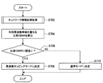
(処理例1)
図34は、本実施形態に係る通信システム1において実行される無線システム制御処理の流れの一例を示すシーケンス図である。図34に示すように、本シーケンスには、受信局100、送信局200、及びサーバ300が関与する。本動作処理例では、サーバ300が通信制御装置として機能する。また、受信局100及び送信局200は、制御対象の無線システム10に含まれるものとする。(Processing example 1)
FIG. 34 is a sequence diagram illustrating an example of a flow of a wireless system control process executed in the
図34に示すように、まず、ステップS102で、サーバ300は、ネットワーク情報のリクエストを送信する。サーバ300は、例えば送信局200へリクエストを送信し、送信局200は受信したリクエストを受信局100へ中継する。
As shown in FIG. 34, first, in step S102, the
次いで、ステップS104で、送信局200は、センシング情報をサーバ300へ返信する。送信局200は、周期的にセンシング情報を取得してもよいし、サーバ300からのリクエストの受信を契機としてセンシング情報を取得してもよい。
Next, in step S104, the transmitting
同様に、ステップS106で、受信局100は、センシング情報をサーバ300へ返信する。図34に示した例では、受信局100は、センシング情報を送信局200へ送信し、送信局200は受信したセンシング情報をサーバ300へ中継する。
Similarly, in step S106, the receiving
そして、ステップS108で、サーバ300は、受信したセンシング情報に基づいて、動作モード決定処理を行う。サーバ300は、動作モード決定処理により、制御対象の無線システム10の動作モードを、周波数ホッピングモード又は通常モードに決定する。ここでの処理は、後に「3−2.動作モード決定処理」で説明するため、ここでの詳細な説明は省略する。以下では、サーバ300が、制御対象の無線システム10の動作モードを、周波数ホッピングモードとして決定した場合の動作処理例を説明する。
Then, in step S108,
ステップS110で、サーバ300は、周波数ホッピング設定決定処理を行う。サーバ300は、周波数ホッピング設定決定処理により、制御対象の無線システム10が利用する周波数ホッピングパターンを決定して、周波数ホッピング設定情報を生成する。ここでの処理は、後に「3−7.周波数ホッピング設定決定処理」で説明するため、ここでの詳細な説明は省略する。
In step S110,
次いで、ステップS112で、サーバ300は、生成した周波数ホッピング設定情報を送信する。図34に示した例では、サーバ300は、送信局200へ周波数ホッピング設定情報を送信し、送信局200は受信した周波数ホッピング設定情報を受信局100へ中継する。
Next, in step S112,
次に、ステップS114で、送信局200は、受信した周波数ホッピング設定情報を復号する。
Next, in step S114, transmitting
同様に、ステップS116で、受信局100は、受信した周波数ホッピング設定情報を復号する。
Similarly, in step S116, receiving
次いで、ステップS118で、送信局200は、復号した周波数ホッピング設定情報に従って、周波数ホッピング方式を設定する。例えば、送信局200は、周波数ホッピング設定情報で指示された規則に従った無線リソースを利用して周波数ホッピングを行うよう設定する。
Next, in step S118, transmitting
次に、ステップS120で、送信局200は、設定した周波数ホッピング方式により周波数ホッピングを行い、データを送信する。例えば、送信局200は、周波数ホッピング設定情報で指示された周波数帯域、時間帯及び場所において、指示された周波数ホッピングパターンで周波数ホッピングを行ってデータを送信する。
Next, in step S120, transmitting
次いで、ステップS122で、受信局100は、復号した周波数ホッピング設定情報に基づいてデータを復号する。例えば、受信局100は、ステップS112において受信した周波数ホッピング設定情報を用いて送信局200が周波数ホッピングを行い、データ送信を行っているものとして復号処理を行い、データを取得する。
Next, in step S122, the receiving
以上、無線システム制御処理の流れの一例を説明した。 The example of the flow of the wireless system control process has been described above.
(処理例2)
図35は、本実施形態に係る通信システム1において実行される無線システム制御処理の流れの一例を示すシーケンス図である。図35に示すように、本シーケンスには、受信局100、送信局200、及びDB400が関与する。本動作処理例では、送信局200が通信制御装置として機能する。また、受信局100及び送信局200は、制御対象の無線システム10に含まれるものとする。(Processing example 2)
FIG. 35 is a sequence diagram illustrating an example of a flow of a wireless system control process executed in the
図35に示すように、まず、ステップS202で、送信局200は、ネットワーク情報のリクエストをDB400へ送信する。
As shown in FIG. 35, first, in step S202, the transmitting
次いで、ステップS204で、送信局200は、DB400からDB登録情報を取得する。
Next, in step S204, the transmitting
次に、ステップS206で、送信局200は、取得したDB登録情報に基づいて、動作モード決定処理を行う。送信局200は、動作モード決定処理により、制御対象の無線システム10、即ち送信局200自身が所属する無線システム10の動作モードを、周波数ホッピングモード又は通常モードに決定する。以下では、送信局200が、制御対象の無線システム10の動作モードを、周波数ホッピングモードとして決定した場合の動作処理例を説明する。
Next, in step S206, the transmitting
ステップS208で、送信局200は、周波数ホッピング設定決定処理を行う。送信局200は、周波数ホッピング設定決定処理により、制御対象の無線システム10が利用する周波数ホッピングパターンを決定して、周波数ホッピング設定情報を生成する。
In step S208, the transmitting
次いで、ステップS210で、送信局200は、生成した周波数ホッピング設定情報を受信局100へ送信する。
Next, in step S210, transmitting
次に、ステップS212で、受信局100は、受信した周波数ホッピング設定情報を復号する。
Next, in step S212, the receiving
次いで、ステップS214で、送信局200は、生成した周波数ホッピング設定情報に従って、周波数ホッピング方式を設定する。
Next, in step S214, transmitting
次に、ステップS216で、送信局200は、設定した周波数ホッピング方式により周波数ホッピングを行い、データを送信する。
Next, in step S216, the transmitting
次いで、ステップS218で、受信局100は、復号した周波数ホッピング設定情報に基づいてデータを復号する。
Next, in step S218, the receiving
以上、無線システム制御処理の流れの一例を説明した。 The example of the flow of the wireless system control process has been described above.
[3−2.動作モード決定処理]
続いて、図36〜図42を参照して、本実施形態に係る通信制御装置300による動作モード決定処理について説明する。この処理は、多様な形態を取り得る。以下では、その一例を説明する。[3-2. Operation mode determination processing]
Subsequently, an operation mode determination process by the
(処理例1)
図36は、本実施形態に係る通信制御装置300において実行される動作モード決定処理の流れの一例を示すフローチャートである。(Processing example 1)
FIG. 36 is a flowchart illustrating an example of the flow of an operation mode determination process performed in the
図36に示すように、まず、ステップS302で、制御部320は、ネットワーク情報の取得が必要であるか否かを判定する。例えば、制御部320は、米国Federal SAS、又は欧州LSAなどの、無線システム10が使用される国の電波法制に基づいて、ネットワーク情報の取得が必要であるか否かを判定する。
As shown in FIG. 36, first, in step S302,
ネットワーク情報の取得が必要であると判定された場合(S302/YES)、ステップS304で、制御部320は、ネットワーク情報取得処理を行う。ここでの処理は、後に「3−3.ネットワーク情報取得処理」で説明するため、ここでの詳細な説明は省略する。制御部320は、ネットワーク情報取得処理により、ネットワーク情報を取得する。
If it is determined that acquisition of network information is necessary (S302 / YES),
次いで、ステップS306で、制御部320は、制御対象の無線システム10の動作モードを周波数ホッピングモードに決定する。
Next, in step S306, the
一方で、ネットワーク情報の取得が必要でないと判定された場合(S302/NO)、ステップS308で、制御部320は、制御対象の無線システム10の動作モードを通常モードに決定する。
On the other hand, when it is determined that the acquisition of the network information is not necessary (S302 / NO), in step S308, the
以上、動作モード決定処理の流れの一例を説明した。 The example of the flow of the operation mode determination process has been described above.
(処理例2)
図37は、本実施形態に係る通信制御装置300において実行される動作モード決定処理の流れの一例を示すフローチャートである。(Processing example 2)
FIG. 37 is a flowchart illustrating an example of the flow of an operation mode determination process performed in the
図37に示すように、まず、ステップS402で、制御部320は、ネットワーク情報の取得が必要であるか否かを判定する。
As shown in FIG. 37, first, in step S402, the
ネットワーク情報の取得が必要であると判定された場合(S402/YES)、ステップS404で、制御部320は、ネットワーク情報取得処理を行う。
When it is determined that acquisition of network information is necessary (S402 / YES), in step S404,
次いで、ステップS406で、制御部320は、制御対象の無線システム10より優先度が高い他の無線システム10が存在する可能性があるか否かを判定する。例えば、制御部320は、取得したネットワーク情報から、優先度が高い他の無線システム10の存在する可能性を判定する。
Next, in step S406, the
制御対象の無線システム10より優先度が高い他の無線システム10が存在する可能性があると判定された場合(S406/YES)、ステップS408で、制御部320は、制御対象の無線システム10の動作モードを周波数ホッピングモードに決定する。
When it is determined that there is a possibility that another wireless system 10 having a higher priority than the wireless system 10 to be controlled exists (S406 / YES), the
一方で、ネットワーク情報の取得が必要でないと判定された場合(S402/NO)、又は制御対象の無線システム10より優先度が高い他の無線システム10が存在する可能性がないと判定された場合(S406/NO)、ステップS410で、制御部320は、制御対象の無線システム10の動作モードを通常モードに決定する。
On the other hand, when it is determined that acquisition of network information is not necessary (S402 / NO), or when it is determined that there is no possibility that another wireless system 10 having a higher priority than the wireless system 10 to be controlled exists. (S406 / NO), in step S410, the
以上、動作モード決定処理の流れの一例を説明した。 The example of the flow of the operation mode determination process has been described above.
(処理例3)
図38は、本実施形態に係る通信制御装置300において実行される動作モード決定処理の流れの一例を示すフローチャートである。(Processing example 3)
FIG. 38 is a flowchart illustrating an example of the flow of an operation mode determination process performed in the
図38に示すように、まず、ステップS502で、制御部320は、ネットワーク情報取得処理を行う。
As shown in FIG. 38, first, in step S502, the
次いで、ステップS504で、制御部320は、干渉判定処理を行う。制御部320は、干渉判定処理により、制御対象の無線システム10が干渉する可能性がある他の無線システム10が存在するか否かを判定する。ここでの処理は、後に「3−4.干渉判定処理」で説明するため、ここでの詳細な説明は省略する。
Next, in step S504, the
干渉する可能性がある他の無線システム10が存在すると判定された場合(S506/YES)、ステップS508で、制御部320は、制御対象の無線システム10の動作モードを周波数ホッピングモードに決定する。
When it is determined that there is another wireless system 10 that may interfere (S506 / YES), in step S508, the
一方で、干渉する可能性がある他の無線システム10が存在しないと判定された場合(S506/NO)、ステップS510で、制御部320は、制御対象の無線システム10の動作モードを通常モードに決定する。
On the other hand, when it is determined that there is no other wireless system 10 that may interfere (S506 / NO), in step S510, the
以上、動作モード決定処理の流れの一例を説明した。 The example of the flow of the operation mode determination process has been described above.
(処理例4)
図39は、本実施形態に係る通信制御装置300において実行される動作モード決定処理の流れの一例を示すフローチャートである。(Processing example 4)
FIG. 39 is a flowchart illustrating an example of the flow of an operation mode determination process performed in the
図39に示すように、まず、ステップS602で、制御部320は、ネットワーク情報取得処理を行う。
As shown in FIG. 39, first, in step S602, the
次いで、ステップS604で、制御部320は、干渉判定処理を行う。
Next, in Step S604, the
干渉する可能性がある他の無線システム10が存在すると判定された場合(S606/YES)、ステップS608で、制御部320は、制御対象の無線システム10より優先度が高い他の無線システム10が存在する可能性があるか否かを判定する。
When it is determined that there is another wireless system 10 that may interfere (S606 / YES), in step S608, the
制御対象の無線システム10より優先度が高い他の無線システム10が存在する可能性があると判定された場合(S608/YES)、ステップS610で、制御部320は、制御対象の無線システム10の動作モードを周波数ホッピングモードに決定する。
When it is determined that there is a possibility that another wireless system 10 with a higher priority than the wireless system 10 to be controlled exists (S608 / YES), the
一方で、干渉する可能性がある他の無線システム10が存在しないと判定された場合(S606/NO)、又は制御対象の無線システム10より優先度が高い他の無線システム10が存在する可能性がないと判定された場合(S608/NO)、ステップS612で、制御部320は、制御対象の無線システム10の動作モードを通常モードに決定する。
On the other hand, when it is determined that there is no other wireless system 10 that may cause interference (S606 / NO), there is a possibility that another wireless system 10 with a higher priority than the wireless system 10 to be controlled exists. When it is determined that there is no control mode (S608 / NO), the
以上、動作モード決定処理の流れの一例を説明した。 The example of the flow of the operation mode determination process has been described above.
(処理例5)
図40は、本実施形態に係る通信制御装置300において実行される動作モード決定処理の流れの一例を示すフローチャートである。(Processing example 5)
FIG. 40 is a flowchart illustrating an example of the flow of an operation mode determination process performed in the
図40に示すように、まず、ステップS702で、制御部320は、ネットワーク情報取得処理を行う。
As shown in FIG. 40, first, in step S702, the
次いで、ステップS704で、制御部320は、利用周波数帯域の重なる比率OBWRを算出する。ここでの処理は、後述するため、ここでの詳細な説明は省略する。
Next, in step S704, the
次に、ステップS706で、制御部320は、比率OBWRが閾値λより大きいか否かを判定する。
Next, in step S706, the
比率OBWRが閾値λより大きいと判定された場合(S706/YES)、ステップS708で、制御部320は、制御対象の無線システム10の動作モードを周波数ホッピングモードに決定する。
When it is determined that the ratio OBWR is larger than the threshold λ (S706 / YES), in step S708, the
比率OBWRが閾値λ以下であると判定された場合(S706/NO)、ステップS710で、制御部320は、制御対象の無線システム10の動作モードを通常モードに決定する。
When it is determined that the ratio OBWR is equal to or smaller than the threshold λ (S706 / NO), in step S710, the
以上、動作モード決定処理の流れの一例を説明した。ここで、ステップS704における、比率OBWRの算出処理の具体的な流れの一例を、図41を参照して説明する。 The example of the flow of the operation mode determination process has been described above. Here, an example of a specific flow of the calculation process of the ratio OBWR in step S704 will be described with reference to FIG.
図41は、本実施形態に係る通信制御装置300において実行される利用周波数帯域が重なる比率の算出処理の流れの一例を示すフローチャートである。なお、本フローチャートでは、図24〜図27で用いた記号F1H、F1L、F2H、及びF2Lを用いて、比率OBWRの算出処理を説明する。
FIG. 41 is a flowchart illustrating an example of a flow of a process of calculating a ratio of overlapping use frequency bands, which is performed in the
図41に示すように、まず、ステップS802で、制御部320は、(F1H<F2L)又は(F2H<F1L)の条件を満たすか否かを判定する。本条件を満たすと判定された場合(S802/YES)、ステップS804で、制御部320は、OBWR=0.0を算出する。一方で、本条件を満たさないと判定された場合(S802/NO)、処理はステップS806に進む。
As shown in FIG. 41, first, in step S802, the
ステップS806で、制御部320は、(F1H≧F2L)且つ(F2H>F1L)の条件を満たすか否かを判定する。本条件を満たすと判定された場合(S806/YES)、ステップS808で、制御部320は、OBWR=(F1H−F2L)/(F1H−F1L)を算出する。一方で、本条件を満たさないと判定された場合(S806/NO)、処理はステップS810に進む。
In step S806,
ステップS810で、制御部320は、(F2H≧F1L)且つ(F1H>F2L)の条件を満たすか否かを判定する。本条件を満たすと判定された場合(S810/YES)、ステップS812で、制御部320は、OBWR=(F1H−F2L)/(F1H−F1L)を算出する。一方で、本条件を満たさないと判定された場合(S810/NO)、処理はステップS814に進む。
In step S810,
ステップS814で、制御部320は、(F1L<F2L)且つ(F1H>F2H)の条件、又は(F2L≦F1L)且つ(F2H≧F1H)の条件を満たすか否かを判定する。本条件を満たすと判定された場合(S814/YES)、ステップS816で、制御部320は、OBWR=(F2H−F2L)/(F1H−F1L)を算出する。一方で、本条件を満たさないと判定された場合(S810/NO)、処理はステップS804に進む。なお、本条件を満たさない場合を想定することは困難であるため、制御部320は、ステップS814における判定処理を省略して、ステップS816へ進んでもよい。
In step S814, the
以上、比率OBWRの算出処理例を説明した。 The example of the calculation process of the ratio OBWR has been described above.
(処理例6)
図42は、本実施形態に係る通信制御装置300において実行される動作モード決定処理の流れの一例を示すフローチャートである。(Processing example 6)
FIG. 42 is a flowchart illustrating an example of the flow of an operation mode determination process performed in the
図42に示すように、まず、ステップS902で、制御部320は、ネットワーク情報取得処理を行う。
As shown in FIG. 42, first, in step S902, the
次いで、ステップS904で、制御部320は、干渉判定処理を行う。
Next, in step S904, the
干渉する可能性がある他の無線システム10が存在すると判定された場合(S906/YES)、ステップS908で、制御部320は、利用周波数帯域の重なる比率OBWRを算出する。
When it is determined that there is another wireless system 10 that may interfere (S906 / YES), in step S908, the
次に、ステップS910で、制御部320は、比率OBWRが閾値λより大きいか否かを判定する。
Next, in step S910,
比率OBWRが閾値λより大きいと判定された場合(S910/YES)、ステップS912で、制御部320は、制御対象の無線システム10の動作モードを周波数ホッピングモードに決定する。
When it is determined that the ratio OBWR is larger than the threshold λ (S910 / YES), in step S912, the
比率OBWRが閾値λ以下であると判定された場合(S910/NO)、又は干渉する可能性がある他の無線システム10が存在しないと判定された場合(S906/NO)、ステップS914で、制御部320は、制御対象の無線システム10の動作モードを通常モードに決定する。
When it is determined that the ratio OBWR is equal to or smaller than the threshold λ (S910 / NO), or when it is determined that there is no other wireless system 10 that may interfere (S906 / NO), the control is performed in step S914. The
以上、動作モード決定処理の流れの一例を説明した。 The example of the flow of the operation mode determination process has been described above.
[3−3.ネットワーク情報取得処理]
続いて、図43を参照して、本実施形態に係る通信制御装置300によるネットワーク情報取得処理について説明する。この処理は、多様な形態を取り得る。例えば、通信制御装置300は、ネットワーク情報の取得が必要になったタイミング、又は動作モード決定処理や干渉判定処理などでネットワーク情報を用いるタイミングで、ネットワーク情報を取得してもよい。他にも、通信制御装置300は、周期的にネットワーク情報を取得してもよい。以下では、周期的にネットワーク情報を取得する場合の例を説明する。[3-3. Network information acquisition processing]
Subsequently, a network information acquisition process by the
図43は、本実施形態に係る通信制御装置300において実行されるネットワーク情報取得処理の流れの一例を示すフローチャートである。
FIG. 43 is a flowchart illustrating an example of the flow of the network information acquisition process executed in the
図43に示すように、まず、ステップS1002で、制御部320は、ネットワーク情報を取得するためのタイマーをセットする。
As shown in FIG. 43, first, in step S1002,
次いで、ステップS1002で、制御部320は、セットしたタイマーが満了するまでの間(S1006/NO)、待機する。
Next, in step S1002, the
タイマーが満了した場合(S1006/YES)、制御部320は、ネットワーク情報を取得する。例えば、制御部320は、通信部310を介して、ネットワーク情報のリクエストを送信する。そして、制御部320は、DB400から返信されるDB登録情報、又はセンサ装置500から返信されるセンシング情報の、少なくともいずれかを取得する。
When the timer has expired (S1006 / YES),
以上、ネットワーク情報取得処理の流れの一例を説明した。 The example of the flow of the network information acquisition process has been described above.
[3−4.干渉判定処理]
続いて、図44を参照して、本実施形態に係る通信制御装置300による干渉判定処理について説明する。この処理は、多様な形態を取り得る。以下では、その一例を説明する。[3-4. Interference determination processing]
Subsequently, an interference determination process by the
図44は、本実施形態に係る通信制御装置300において実行される干渉判定処理の流れの一例を示すフローチャートである。
FIG. 44 is a flowchart illustrating an example of the flow of an interference determination process performed in the
図44に示すように、まず、ステップS1102で、制御部320は、干渉判定処理の対象である無線システム10が、制御対象の無線システム10の利用周波数帯域と同一の周波数帯域を利用するか否かを判定する。この判定は、例えばDB登録情報を参照して行われる。なお、制御部320は、利用周波数帯域が完全に同一でなくても、図24〜図27に一例を示したように一部重複している場合に、同一の周波数帯域を利用すると判定してもよい。また、制御部320は、利用周波数帯域が重複していなくても、その差が所定範囲内である場合に、同一の周波数帯域を利用すると判定してもよい。
As shown in FIG. 44, first, in step S1102, the
同一の周波数帯域を利用すると判定された場合(S1102/YES)、ステップS1104で、制御部320は、干渉判定処理の対象である無線システム10が、制御対象の無線システム10の利用周波数帯域と同一の時刻で動作するか否かを判定する。この判定は、例えばDB登録情報を参照して行われる。なお、制御部320は、動作時刻が完全に同一でなくても、一部重複している場合に、同一の時刻で動作すると判定してもよい。また、制御部320は、時刻が重複していなくても、その差が所定範囲内である場合に、同一の時刻で動作すると判定してもよい。
When it is determined that the same frequency band is to be used (S1102 / YES), in step S1104, the
同一の時刻で動作すると判定された場合(S1104/YES)、ステップS1106で、制御部320は、干渉判定処理の対象である無線システム10が、制御対象の無線システム10の利用周波数帯域と同一の場所で動作するか否かを判定する。この判定は、例えばDB登録情報を参照して行われる。なお、制御部320は、運用場所が完全に同一でなくても、一部重複している場合に、同一の場所で動作すると判定してもよい。また、制御部320は、運用場所が重複していなくても、その差が所定範囲内である場合に、同一の場所で動作すると判定してもよい。
When it is determined that the operation is performed at the same time (S1104 / YES), in step S1106, the
同一の場所で動作すると判定された場合(S1106/YES)、ステップS1108で、制御部320は、制御対象の無線システム10が、干渉判定処理の対象である無線システム10に干渉する可能性があると判定する。
If it is determined that they operate in the same place (S1106 / YES), in step S1108, the
一方で、異なる場所で動作すると判定された場合(S1106/NO)、ステップS1110で、制御部320は、制御対象の無線システム10が、干渉判定処理の対象である無線システム10に干渉する可能性がないと判定する。また、制御部320は、異なる周波数帯域を利用すると判定された場合(S1102/NO)、又は異なる時刻で動作すると判定された場合(S1104/NO)に、同様に干渉する可能性がないと判定する。
On the other hand, when it is determined that the operation is performed in a different place (S1106 / NO), in step S1110, the
以上、干渉判定処理の流れの一例を説明した。 The example of the flow of the interference determination process has been described above.
この例では、DB登録情報に基づいて判定がされる例を説明したが、センシング情報に基づいても同様に判定され得る。センシング情報に基づく場合、ステップS1102における処理において、制御部320はセンシング情報に基づいて利用周波数帯域が同一であるか否かを判定する。ここでの処理は、後に「3−5.利用周波数帯域の重複判定処理」で説明するため、ここでの詳細な説明は省略する。なお、制御対象の受信局100若しくは送信局200がセンサ装置500として機能する場合、場所と時刻に関する判定は省略されてもよい。
In this example, an example in which the determination is performed based on the DB registration information has been described. However, the determination may be similarly performed based on the sensing information. If it is based on the sensing information, in the process in step S1102, the
[3−5.利用周波数帯域の重複判定処理]
続いて、図45〜図47を参照して、本実施形態に係る通信制御装置300によるセンシング情報に基づく利用周波数帯域の重複判定処理について説明する。この処理は、多様な形態を取り得る。以下では、その一例を説明する。[3-5. Use frequency band overlap determination process]
Subsequently, with reference to FIGS. 45 to 47, a description will be given of a process of determining the overlap of the used frequency band based on the sensing information by the
(処理例1)
図45は、本実施形態に係る通信制御装置300において実行される利用周波数帯域の重複判定処理の流れの一例を示すフローチャートである。(Processing example 1)
FIG. 45 is a flowchart illustrating an example of the flow of the use frequency band overlap determination process performed in the
図45に示すように、まず、ステップS1202で、制御部320は、制御対象の無線システム10の利用周波数帯域と同一の周波数帯域を利用する他の無線システム10が検出されたか否かを判定する。
As illustrated in FIG. 45, first, in step S1202, the
同一の周波数帯域を利用する他の無線システム10が検出されたと判定された場合(S1202/YES)、ステップS1204で、制御部320は、同一周波数帯域を利用する無線システム10はあると判定する。
When it is determined that another wireless system 10 using the same frequency band has been detected (S1202 / YES), in step S1204,
一方で、同一の周波数帯域を利用する他の無線システム10が検出されていないと判定された場合(S1202/NO)、ステップS1206で、制御部320は、制御対象の無線システム10の利用周波数帯域と同一の周波数帯域から所定範囲内の帯域を利用する他の無線システム10が検出されたか否かを判定する。
On the other hand, when it is determined that another wireless system 10 using the same frequency band has not been detected (S1202 / NO), in step S1206, the
同一の周波数帯域から所定範囲内の帯域を利用する他の無線システム10が検出されたと判定された場合(S1206/YES)、ステップS1204で、制御部320は、同一周波数帯域を利用する無線システム10はあると判定する。
If it is determined that another wireless system 10 using a band within a predetermined range from the same frequency band has been detected (S1206 / YES),
一方で、同一の周波数帯域から所定範囲内の帯域を利用する他の無線システム10が検出されていないと判定された場合(S1206/NO)、ステップS1208で、制御部320は、同一周波数帯域を利用する無線システム10はないと判定する。
On the other hand, when it is determined that another wireless system 10 that uses a band within the predetermined range from the same frequency band is not detected (S1206 / NO), in step S1208, the
以上、センシング情報に基づく利用周波数帯域の重複判定処理の流れの一例を説明した。 In the foregoing, an example of the flow of the use frequency band overlap determination process based on the sensing information has been described.
(処理例2)
図46は、本実施形態に係る通信制御装置300において実行される利用周波数帯域の重複判定処理の流れの一例を示すフローチャートである。(Processing example 2)
FIG. 46 is a flowchart illustrating an example of the flow of the use frequency band overlap determination process performed in the
図46に示すように、ステップS1302〜ステップS1306における処理は、図45を参照して説明した通りであるので、再度の説明は省略する。 As shown in FIG. 46, the processing in steps S1302 to S1306 is the same as that described with reference to FIG. 45, and a description thereof will not be repeated.
ステップS1306において、同一の周波数帯域から所定範囲内の帯域を利用する他の無線システム10が検出されたと判定された場合(S1306/YES)、ステップS1308で、制御部320は、当該他の無線システム10が利用周波数帯域を時変しているか否かを判定する。ここでの処理は、後に「3−6.利用周波数帯域の時変判定処理」で説明するため、ここでの詳細な説明は省略する。
If it is determined in step S1306 that another wireless system 10 that uses a band within a predetermined range from the same frequency band has been detected (S1306 / YES), in step S1308, the
同一の周波数帯域から所定範囲内の帯域を利用する他の無線システム10が利用周波数帯域を時変していると判定された場合(S1308/YES)、ステップS1304で、制御部320は、同一周波数帯域を利用する無線システム10はあると判定する。
If it is determined that another wireless system 10 that uses a band within a predetermined range from the same frequency band is time-varying in the used frequency band (S1308 / YES), in step S1304, the
一方で、同一の周波数帯域から所定範囲内の帯域を利用する他の無線システム10が利用周波数帯域を時変していないと判定された場合(S1308/NO)、ステップS1310で、制御部320は、同一周波数帯域を利用する無線システム10はないと判定する。
On the other hand, when it is determined that another wireless system 10 that uses a band within a predetermined range from the same frequency band does not change the used frequency band (S1308 / NO), in step S1310, the
以上、センシング情報に基づく利用周波数帯域の重複判定処理の流れの一例を説明した。 In the foregoing, an example of the flow of the use frequency band overlap determination process based on the sensing information has been described.
(処理例3)
図47は、本実施形態に係る通信制御装置300において実行される利用周波数帯域の重複判定処理の流れの一例を示すフローチャートである。(Processing example 3)
FIG. 47 is a flowchart illustrating an example of the flow of the use frequency band overlap determination process performed in the
図47に示すように、ステップS1402〜ステップS1408における処理は、図46を参照して説明した通りであるので、再度の説明は省略する。 As shown in FIG. 47, the processing in steps S1402 to S1408 is the same as that described with reference to FIG. 46, and a description thereof will not be repeated.
ステップS1408において、同一の周波数帯域から所定範囲内の帯域を利用する他の無線システム10が利用周波数帯域を時変していると判定された場合(S1408/YES)、ステップS1410で、制御部320は、当該他の無線システム10が、制御対象の無線システムの利用周波数帯域に近づく方向に利用周波数帯域を時変しているか否かを判定する。
In step S1408, when it is determined that another wireless system 10 that uses a band within a predetermined range from the same frequency band changes the used frequency band (S1408 / YES), the
同一の周波数帯域から所定範囲内の帯域を利用する他の無線システム10が、制御対象の無線システムの利用周波数帯域に近づく方向に利用周波数帯域を時変していると判定された場合(S1410/YES)、ステップS1404で、制御部320は、同一周波数帯域を利用する無線システム10はあると判定する。
When it is determined that another wireless system 10 that uses a band within a predetermined range from the same frequency band changes the use frequency band in a direction approaching the use frequency band of the control target wireless system (S1410 / YES), in step S1404,
一方で、同一の周波数帯域から所定範囲内の帯域を利用する他の無線システム10が、制御対象の無線システムの利用周波数帯域に遠ざかる方向に利用周波数帯域を時変していると判定された場合(S1410/NO)、ステップS1412で、制御部320は、同一周波数帯域を利用する無線システム10はないと判定する。
On the other hand, when it is determined that another wireless system 10 that uses a band within a predetermined range from the same frequency band is time-varying the usage frequency band in a direction away from the usage frequency band of the wireless system to be controlled (S1410 / NO), in step S1412,
以上、センシング情報に基づく利用周波数帯域の重複判定処理の流れの一例を説明した。 In the foregoing, an example of the flow of the use frequency band overlap determination process based on the sensing information has been described.
[3−6.利用周波数帯域の時変判定処理]
続いて、図48及び図49を参照して、本実施形態に係る通信制御装置300によるセンシング情報に基づく利用周波数帯域の時変判定処理について説明する。この処理は、多様な形態を取り得る。以下では、その一例を説明する。[3-6. Time-varying judgment processing of used frequency band]
Next, with reference to FIG. 48 and FIG. 49, a description will be given of the time-varying determination processing of the used frequency band based on the sensing information by the
(処理例1)
図48は、本実施形態に係る通信制御装置300において実行される利用周波数帯域の時変判定処理の流れの一例を示すフローチャートである。なお、本フローチャートでは、図23を参照して上記説明した、離散的に帯域幅がセンシングされた場合の判定処理を説明する。記号#−N〜#Nは、帯域幅のインデックスを示す。(Processing example 1)
FIG. 48 is a flowchart illustrating an example of the flow of the time-varying determination process of the used frequency band performed in the
図48に示すように、まず、ステップS1502で、制御部320は、時刻tにおいて帯域#iで他の無線システム10が検出されたか否かを判定する。
As shown in FIG. 48, first, in step S1502,
時刻tにおいて帯域#iで他の無線システム10が検出された場合(S1502/YES)、ステップS1504で、制御部320は、時刻t+t´において帯域#i+nで当該無線システムが検出されたか否かを判定する。なお、時刻tにおいて帯域#iで他の無線システム10が検出されていない場合(S1502/NO)、処理は後述のステップS1512へ進む。
When another wireless system 10 is detected in band #i at time t (S1502 / YES), in step S1504,
時刻t+t´において帯域#i+nで当該無線システムが検出された場合(S1504/YES)、ステップS1506で、制御部320は、検出された無線システムは利用周波数帯域を低→高に時変していると判定する。
When the wireless system is detected in band # i + n at time t + t ′ (S1504 / YES), in step S1506,
一方で、時刻t+t´において帯域#i+nで当該無線システムが検出されていない場合(S1504/NO)、ステップS1508で、制御部320は、時刻t+t´において帯域#i−mで当該無線システムが検出されたか否かを判定する。
On the other hand, when the wireless system is not detected in band # i + n at time t + t ′ (S1504 / NO), in step S1508,
時刻t+t´において帯域#i−mで当該無線システムが検出された場合(S1508/YES)、ステップS1510で、制御部320は、検出された無線システムは利用周波数帯域を高→低に時変していると判定する。
When the wireless system is detected in band #im at time t + t ′ (S1508 / YES), in step S1510,
時刻t+t´において帯域#i−mで当該無線システムが検出されていない場合(S1508/NO)、ステップS1512で、制御部320は、検出された無線システムは利用周波数帯域を時変していないと判定する。
If the wireless system is not detected in the band #im at time t + t ′ (S1508 / NO), in step S1512, the
以上、センシング情報に基づく利用周波数帯域の時変判定処理の流れの一例を説明した。 As above, an example of the flow of the time-varying determination process of the use frequency band based on the sensing information has been described.
(処理例2)
図49は、本実施形態に係る通信制御装置300において実行される利用周波数帯域の時変判定処理の流れの一例を示すフローチャートである。なお、本フローチャートでは、図23を参照して上記説明した、離散的に帯域幅がセンシングされた場合の判定処理を説明する。記号#−N〜#Nは、帯域幅のインデックスを示す。(Processing example 2)
FIG. 49 is a flowchart illustrating an example of the flow of the time-variation determination process of the used frequency band executed in the
図49に示すように、ステップS1502、S1504、S1506、S1508、S1510、及びS1512における処理は、図48を参照して上記説明した通りであるので、再度の説明は省略する。本処理例は、図48を参照して説明した処理例に、ステップS1505及びS1509を追加している。 As shown in FIG. 49, the processes in steps S1502, S1504, S1506, S1508, S1510, and S1512 are the same as those described above with reference to FIG. 48, and thus description thereof will not be repeated. In this processing example, steps S1505 and S1509 are added to the processing example described with reference to FIG.
時刻t+t´において帯域#i+nで当該無線システムが検出された場合(S1504/YES)、ステップS1505で、制御部320は、時刻t+2t´において帯域#i+2nで当該無線システムが検出されたか否かを判定する。そして、時刻t+2t´において帯域#i+2nで当該無線システムが検出された場合(S1505/YES)、処理はステップS1506へ進む。また、時刻t+2t´において帯域#i+2nで当該無線システムが検出されていない場合(S1505/NO)、処理はステップS1512へ進む。
If the wireless system is detected in band # i + n at time t + t '(S1504 / YES),
時刻t+t´において帯域#i−mで当該無線システムが検出された場合(S1508/YES)、ステップS1509で、制御部320は、時刻t+2t´において帯域#i−2mで当該無線システムが検出されたか否かを判定する。そして、時刻t+2t´において帯域#i−2mで当該無線システムが検出された場合(S1509/YES)、処理はステップS1510へ進む。また、時刻t+2t´において帯域#i−2mで当該無線システムが検出されていない場合(S1509/NO)、処理はステップS1512へ進む。
When the wireless system is detected in band #im at time t + t '(S1508 / YES),
以上、センシング情報に基づく利用周波数帯域の時変判定処理の流れの一例を説明した。 As above, an example of the flow of the time-varying determination process of the use frequency band based on the sensing information has been described.
本処理例で説明したように、制御部320は、周波数帯域の変化状態を複数回確認することができる。また、制御部320は、このような時変判定処理を繰り返すこともできる。これにより、制御部320は、無線システム10が利用周波数帯域を時変しているか否かを、より高精度に判定することができる。なお、図49では、周波数帯域の変化状態を、時刻t、t+t´、t+2t´のように等間隔で確認しているが、異なる間隔で確認してもよい。同様に、図49では、周波数帯域の変化状態を、帯域#i、#i+n、#i+2nのように等間隔で確認しているが、異なる間隔で確認してもよい。
As described in this processing example, the
[3−7.周波数ホッピング設定決定処理]
続いて、図50〜図52を参照して、本実施形態に係る通信制御装置300による周波数ホッピング設定情報決定処理について説明する。この処理は、多様な形態を取り得る。以下では、その一例を説明する。[3-7. Frequency hopping setting decision processing]
Subsequently, the frequency hopping setting information determination processing by the
(処理例1)
図50は、本実施形態に係る通信制御装置300において実行される周波数ホッピング設定情報決定処理の流れの一例を示すフローチャートである。(Processing example 1)
FIG. 50 is a flowchart illustrating an example of a flow of frequency hopping setting information determination processing executed in
図50に示すように、まず、ステップS1602で、制御部320は、制御対象の無線システム10と他の無線システム10とで利用周波数帯域が重なる部分の無線リソースの利用方式を決定する。例えば、制御部320は、重なる部分において制御対象の無線システム10が周波数ホッピングを行うよう決定すると共に、ホッピングパターンを決定する。なお、重なる部分が無い場合には、制御部320は、本処理を省略する。
As illustrated in FIG. 50, first, in step S1602, the
次いで、ステップS1604で、制御部320は、制御対象の無線システム10と他の無線システム10とで利用周波数帯域が重ならない部分の無線リソースの利用方式を決定する。例えば、制御部320は、重ならない部分のうち制御対象の無線システム10が周波数ホッピングを行わずに利用する周波数帯域の範囲を決定する。制御部320は、重ならない部分でも周波数ホッピングを行うよう決定してもよい。なお、重ならない部分が無い場合には、制御部320は、本処理を省略する。
Next, in step S1604, the
次に、ステップS1606で、制御部320は、周波数ホッピング設定情報を生成する。周波数ホッピング設定情報には、上記ステップS1602〜S1606で決定した、周波数ホッピングを行う周波数帯域、周波数ホッピングパターン、及び周波数ホッピングを行わずに利用する周波数帯域を示す情報が含まれる。なお、制御部320は、干渉する可能性がある無線システム10の情報に応じて制御対象の無線システム10が周波数ホッピングを行う時間帯、場所等を決定してもよく、周波数ホッピング設定情報にこれらを示す情報が含まれてもよい。
Next, in step S1606,
以上、周波数ホッピング設定情報決定処理の流れの一例を説明した。 The example of the flow of the frequency hopping setting information determination processing has been described above.
(処理例2)
図51は、本実施形態に係る通信制御装置300において実行される周波数ホッピング設定情報決定処理の流れの一例を示すフローチャートである。(Processing example 2)
FIG. 51 is a flowchart illustrating an example of a flow of frequency hopping setting information determination processing executed in the
図51に示すように、まず、ステップS1702で、制御部320は、他の無線システムに関する情報が更新されたか否かを判定する。例えば、制御部320は、通信部310を介してDB400に更新有無を問い合わせる。
As shown in FIG. 51, first, in step S1702,
更新されていないと判定された場合(S1702/NO)、処理はステップS1702に戻る。 If it is determined that it has not been updated (S1702 / NO), the process returns to step S1702.
一方で、更新されたと判定された場合(S1702/YES)、処理はステップS1704へ進む。ステップS1704〜S1708における処理は、図50を参照して上記説明したステップS1602〜S1606における処理と同様であるため、再度の説明は省略する。 On the other hand, if it is determined that the information has been updated (S1702 / YES), the process proceeds to step S1704. The processing in steps S1704 to S1708 is the same as the processing in steps S1602 to S1606 described above with reference to FIG. 50, and a description thereof will not be repeated.
このように、周波数ホッピング設定情報決定処理は、定期的に実行されてもよい。他にも、情報更新以外の任意の事象が実行のトリガであってもよい。例えば、ネットワーク情報から他の無線システム10の存在が判断されることをトリガとして、周波数ホッピング設定情報決定処理が実行されてもよい。 As described above, the frequency hopping setting information determination processing may be executed periodically. In addition, any event other than the information update may be a trigger for execution. For example, the frequency hopping setting information determination processing may be executed with a trigger that the presence of another wireless system 10 is determined from the network information as a trigger.
以上、周波数ホッピング設定情報決定処理の流れの一例を説明した。 The example of the flow of the frequency hopping setting information determination processing has been described above.
上記ステップS1602(図50)及びS1704(図51)の周波数ホッピング設定情報決定処理において、周波数ホッピングパターンの決定の際に、他の無線システム10で利用される周波数ホッピングパターンの情報が加味され得る。以下では、図52を参照して、このような場合における周波数ホッピングパターンの決定処理の一例を説明する。 In the frequency hopping setting information determination processing in steps S1602 (FIG. 50) and S1704 (FIG. 51), information on the frequency hopping pattern used in another wireless system 10 can be added when the frequency hopping pattern is determined. Hereinafter, an example of the process of determining the frequency hopping pattern in such a case will be described with reference to FIG.
図52は、本実施形態に係る通信制御装置300において実行される周波数ホッピングパターン決定処理の流れの一例を示すフローチャートである。
FIG. 52 is a flowchart illustrating an example of a flow of a frequency hopping pattern determination process performed in the
図52に示すように、まず、ステップS1802で、制御部320は、他の無線システム10の周波数ホッピングパターンは既知であるか否かを判定する。例えば、制御部320は、取得したネットワーク情報を参照して、他の無線システム10の周波数ホッピングパターンが既知であるか否かを判定する。
As shown in FIG. 52, first, in step S1802,
既知であると判定された場合(S1802/YES)、ステップS1804で、制御部320は、他の無線システム10が利用していない周波数ホッピングパターンがあるか否かを判定する。
If it is determined that it is known (S1802 / YES), in step S1804, the
利用していない周波数ホッピングパターンがある場合(S1804/YES)、ステップS1806で、制御部320は、他の無線システム10が利用していない周波数ホッピングパターンの中から利用するパターンを決定する。
If there is a frequency hopping pattern that is not used (S1804 / YES), in step S1806,
一方で、他の無線システム10の周波数ホッピングパターンが既知でないと判定された場合(S1802/NO)、又は既知であるが利用していない周波数ホッピングパターンがないと判定された場合(S1804/NO)、ステップS1808で、制御部320は、他の無線システム10が利用している周波数ホッピングパターンを考慮せずに利用するパターンを決定する。
On the other hand, when it is determined that the frequency hopping pattern of another wireless system 10 is not known (S1802 / NO), or when it is determined that there is no known but unused frequency hopping pattern (S1804 / NO). In step S1808, the
以上、周波数ホッピングパターン決定処理の流れの一例を説明した。 The example of the flow of the frequency hopping pattern determination process has been described above.
[3−8.DB登録情報登録処理]
続いて、図53〜図54を参照して、本実施形態に係るDB400に登録されるDB登録情報の登録処理について説明する。まず、図53を参照して、DB400における周波数ホッピングパターンを示す情報の登録処理について説明する。この処理は、多様な形態を取り得る。以下では、その一例を説明する。[3-8. DB registration information registration processing]
Subsequently, a registration process of DB registration information registered in the
図53は、本実施形態に係る通信システム1において実行されるDB登録情報登録処理の流れの一例を示すシーケンス図である。図53に示すように、本シーケンスには、MME300A、DB400、及び基地局300Bが関与する。MME300Aと基地局300Bとは、それぞれ異なる無線システム10に属し、それぞれが属する無線システム10を制御対象とする通信制御装置300として機能するものとする。
FIG. 53 is a sequence diagram illustrating an example of the flow of the DB registration information registration process executed in the
ステップS1902〜S1908で、MME300Aは、図35を参照して上記説明したステップS202〜S208における処理と同様の処理を行う。
In steps S1902 to S1908, the
ステップS1908の後、ステップS1910で、MME300Aは、ステップS1908において決定した周波数ホッピングパターンを示す情報を、DB400へ送信する。
After step S1908, in step S1910, the
そして、ステップS1912で、DB400は、受信した周波数ホッピングパターンを示す情報を登録する。このとき、DB400は、送信元のMME300Aが所属する無線システム10のDB登録情報として、受信された周波数ホッピングパターンを示す情報を記憶する。
Then, in step S1912,
次いで、ステップS1914〜S1920で、基地局300Bは、図35を参照して上記説明したステップS202〜S208における処理と同様の処理を行う。ここで、ステップS1916で基地局300Bが受信するDB登録情報には、MME300Aが属する無線システム10が利用する周波数ホッピングパターンを示す情報が含まれる。このため、ステップS1920の周波数ホッピング設定決定処理において、基地局300Bは、MME300Aが属する無線システム10が利用する周波数ホッピングパターン以外の中から、利用する周波数ホッピングパターンを決定する。
Next, in steps S1914 to S1920, the
次に、ステップS1922で、基地局300Bは、ステップS1920において決定した周波数ホッピングパターンを示す情報を、DB400へ送信する。
Next, in Step S1922, the
そして、ステップS1924で、DB400は、受信した周波数ホッピングパターンを示す情報を登録する。
Then, in step S1924,
以上、DB登録情報登録処理の流れの一例を説明した。 The example of the flow of the DB registration information registration process has been described above.
上記ステップS1910及びS1922(図53)で送信される周波数ホッピングパターンを示す情報は、各無線システム10が周波数ホッピングを行うか否かにより変わり得る。以下、図54を参照して、周波数ホッピングパターンを示す情報の送信処理の一例を説明する。 The information indicating the frequency hopping pattern transmitted in steps S1910 and S1922 (FIG. 53) can be changed depending on whether or not each wireless system 10 performs frequency hopping. Hereinafter, an example of processing for transmitting information indicating a frequency hopping pattern will be described with reference to FIG.
図54は、本実施形態に係る通信制御装置300において実行される周波数ホッピングパターンを示す情報の送信処理の流れの一例を示すフローチャートである。
FIG. 54 is a flowchart illustrating an example of a flow of a process of transmitting information indicating a frequency hopping pattern, which is performed in the
図54に示すように、まず、ステップS2002で、制御部320は、動作モード決定処理を行う。
As shown in FIG. 54, first, in step S2002,
次いで、ステップS2004で、制御部320は、周波数ホッピングモードで動作するか否かを判定する。
Next, in step S2004,
周波数ホッピングモードで動作すると判定された場合(S2004/YES)、ステップS2006で、制御部320は、周波数ホッピング設定決定処理を行う。
When it is determined that the operation is performed in the frequency hopping mode (S2004 / YES), in step S2006,
そして、ステップS2008で、通信部310は、ステップS2006で制御部320が利用すると決定した周波数ホッピングパターンを示す情報を、DB400に通知する。
Then, in step S2008,
一方で、周波数ホッピングモードで動作しないと判定された場合(S2004/NO)、ステップS2010で、通信部310は、通常モードで動作することをDB400に通知する。なお、DB400が、周波数ホッピングパターンを示す情報の通知を受けない場合に、その無線システム10では周波数ホッピングを行わないとみなす場合には、本ステップは省略されてもよい。
On the other hand, when it is determined that the
以上、周波数ホッピングパターンを示す情報の送信処理の一例を説明した。 The example of the process of transmitting the information indicating the frequency hopping pattern has been described above.
[3−9.送信設定切替処理]
続いて、図55を参照して、本実施形態に係る送信局200による送信設定切替処理について説明する。[3-9. Transmission setting switching process]
Subsequently, a transmission setting switching process by the transmitting
図55は、本実施形態に係る送信局200において実行される送信設定切替処理の流れの一例を示すフローチャートである。
FIG. 55 is a flowchart illustrating an example of the flow of the transmission setting switching process performed in the transmitting
図55に示すように、まず、ステップS2102で、送信局200の制御部220は、周波数ホッピングを適用するか否かを判定する。例えば、制御部220は、通信制御装置300から通知された周波数ホッピング設定情報を参照して本判定を行う。
As shown in FIG. 55, first, in step S2102,
周波数ホッピングを適用すると判定された場合(S2102/YES)、制御部220は、フィルタリング係数を周波数ホッピングON用に設定し(ステップS2104)、アップサンプリングONを設定し(ステップS2106)、CP付加OFFを設定する(ステップS2108)。
If it is determined that frequency hopping is to be applied (S2102 / YES), the
一方で、周波数ホッピングを適用しないと判定された場合(S2102/NO)、制御部220は、フィルタリング係数を周波数ホッピングOFF用に設定し(ステップS2110)、アップサンプリングOFFを設定し(ステップS2112)、CP付加ONを設定する(ステップS2114)。なお、周波数ホッピングOFF用のフィルタリング係数は、例えば上記数式2に示した、通常のOFDM用のフィルタリング係数であってもよい。
On the other hand, if it is determined that frequency hopping is not to be applied (S2102 / NO), the
なお、本フローでは、制御部220は、フィルタリング及びCP付加のON/OFFの判断基準を、周波数ホッピングのON/OFFとしたが、本技術はかかる例に限定されない。例えば、制御部220は、周波数ホッピングのON/OFFの判断基準として上記説明した、例えば他の無線システム10の有無に応じてフィルタリング及びCP付加のON/OFFを判断してもよい。
In the present flow, the
<4.応用例>
本開示に係る技術は、様々な製品へ応用可能である。例えば、通信制御装置300は、タワーサーバ、ラックサーバ、又はブレードサーバなどのいずれかの種類のサーバとして実現されてもよい。また、通信制御装置300は、サーバに搭載される制御モジュール(例えば、1つのダイで構成される集積回路モジュール、又はブレードサーバのスロットに挿入されるカード若しくはブレード)であってもよい。<4. Application>
The technology according to the present disclosure is applicable to various products. For example, the
また、例えば、受信局100又は送信局200は、マクロeNB又はスモールeNBなどのいずれかの種類のeNB(evolved Node B)として実現されてもよい。スモールeNBは、ピコeNB、マイクロeNB又はホーム(フェムト)eNBなどの、マクロセルよりも小さいセルをカバーするeNBであってよい。その代わりに、受信局100又は送信局200は、NodeB又はBTS(Base Transceiver Station)などの他の種類の基地局として実現されてもよい。受信局100又は送信局200は、無線通信を制御する本体(基地局装置ともいう)と、本体とは別の場所に配置される1つ以上のRRH(Remote Radio Head)とを含んでもよい。また、後述する様々な種類の端末が一時的に又は半永続的に基地局機能を実行することにより、受信局100又は送信局200として動作してもよい。
Further, for example, the receiving
また、例えば、受信局100又は送信局200は、スマートフォン、タブレットPC(Personal Computer)、ノートPC、携帯型ゲーム端末、携帯型/ドングル型のモバイルルータ若しくはデジタルカメラなどのモバイル端末、又はカーナビゲーション装置などの車載端末として実現されてもよい。また、受信局100又は送信局200は、M2M(Machine To Machine)通信を行う端末(MTC(Machine Type Communication)端末ともいう)として実現されてもよい。さらに、受信局100又は送信局200は、これら端末に搭載される無線通信モジュール(例えば、1つのダイで構成される集積回路モジュール)であってもよい。
Also, for example, the receiving
[4−1.サーバに関する応用例]
図56は、本開示に係る技術が適用され得るサーバ700の概略的な構成の一例を示すブロック図である。サーバ700は、プロセッサ701、メモリ702、ストレージ703、ネットワークインタフェース704及びバス706を備える。[4-1. Application example on server]
FIG. 56 is a block diagram illustrating an example of a schematic configuration of a
プロセッサ701は、例えばCPU(Central Processing Unit)又はDSP(Digital Signal Processor)であってよく、サーバ700の各種機能を制御する。メモリ702は、RAM(Random Access Memory)及びROM(Read Only Memory)を含み、プロセッサ701により実行されるプログラム及びデータを記憶する。ストレージ703は、半導体メモリ又はハードディスクなどの記憶媒体を含み得る。
The
ネットワークインタフェース704は、サーバ700を有線通信ネットワーク705に接続するための有線通信インタフェースである。有線通信ネットワーク705は、EPC(Evolved Packet Core)などのコアネットワークであってもよく、又はインターネットなどのPDN(Packet Data Network)であってもよい。
The
バス706は、プロセッサ701、メモリ702、ストレージ703及びネットワークインタフェース704を互いに接続する。バス706は、速度の異なる2つ以上のバス(例えば、高速バス及び低速バス)を含んでもよい。
The
図56に示したサーバ700において、図18を用いて説明した通信部310及び制御部320は、プロセッサ701において実装されてもよい。例えば、サーバ700は、制御対象の無線システム10において周波数ホッピングを行うよう制御することで、制御対象の無線システム10による他の無線システム10への干渉を低減することができる。
In the
[4−2.基地局に関する応用例]
(第1の応用例)
図57は、本開示に係る技術が適用され得るeNBの概略的な構成の第1の例を示すブロック図である。eNB800は、1つ以上のアンテナ810、及び基地局装置820を有する。各アンテナ810及び基地局装置820は、RFケーブルを介して互いに接続され得る。[4-2. Application example for base station]
(First application example)
FIG. 57 is a block diagram illustrating a first example of a schematic configuration of an eNB to which the technology according to the present disclosure can be applied. The
アンテナ810の各々は、単一の又は複数のアンテナ素子(例えば、MIMOアンテナを構成する複数のアンテナ素子)を有し、基地局装置820による無線信号の送受信のために使用される。eNB800は、図57に示したように複数のアンテナ810を有し、複数のアンテナ810は、例えばeNB800が使用する複数の周波数帯域にそれぞれ対応してもよい。なお、図57にはeNB800が複数のアンテナ810を有する例を示したが、eNB800は単一のアンテナ810を有してもよい。
Each of the
基地局装置820は、コントローラ821、メモリ822、ネットワークインタフェース823及び無線通信インタフェース825を備える。
The
コントローラ821は、例えばCPU又はDSPであってよく、基地局装置820の上位レイヤの様々な機能を動作させる。例えば、コントローラ821は、無線通信インタフェース825により処理された信号内のデータからデータパケットを生成し、生成したパケットをネットワークインタフェース823を介して転送する。コントローラ821は、複数のベースバンドプロセッサからのデータをバンドリングすることによりバンドルドパケットを生成し、生成したバンドルドパケットを転送してもよい。また、コントローラ821は、無線リソース管理(Radio Resource Control)、無線ベアラ制御(Radio Bearer Control)、移動性管理(Mobility Management)、流入制御(Admission Control)又はスケジューリング(Scheduling)などの制御を実行する論理的な機能を有してもよい。また、当該制御は、周辺のeNB又はコアネットワークノードと連携して実行されてもよい。メモリ822は、RAM及びROMを含み、コントローラ821により実行されるプログラム、及び様々な制御データ(例えば、端末リスト、送信電力データ及びスケジューリングデータなど)を記憶する。
The
ネットワークインタフェース823は、基地局装置820をコアネットワーク824に接続するための通信インタフェースである。コントローラ821は、ネットワークインタフェース823を介して、コアネットワークノード又は他のeNBと通信してもよい。その場合に、eNB800と、コアネットワークノード又は他のeNBとは、論理的なインタフェース(例えば、S1インタフェース又はX2インタフェース)により互いに接続されてもよい。ネットワークインタフェース823は、有線通信インタフェースであってもよく、又は無線バックホールのための無線通信インタフェースであってもよい。ネットワークインタフェース823が無線通信インタフェースである場合、ネットワークインタフェース823は、無線通信インタフェース825により使用される周波数帯域よりもより高い周波数帯域を無線通信に使用してもよい。
The
無線通信インタフェース825は、LTE(Long Term Evolution)又はLTE−Advancedなどのいずれかのセルラー通信方式をサポートし、アンテナ810を介して、eNB800のセル内に位置する端末に無線接続を提供する。無線通信インタフェース825は、典型的には、ベースバンド(BB)プロセッサ826及びRF回路827などを含み得る。BBプロセッサ826は、例えば、符号化/復号、変調/復調及び多重化/逆多重化などを行なってよく、各レイヤ(例えば、L1、MAC(Medium Access Control)、RLC(Radio Link Control)及びPDCP(Packet Data Convergence Protocol))の様々な信号処理を実行する。BBプロセッサ826は、コントローラ821の代わりに、上述した論理的な機能の一部又は全部を有してもよい。BBプロセッサ826は、通信制御プログラムを記憶するメモリ、当該プログラムを実行するプロセッサ及び関連する回路を含むモジュールであってもよく、BBプロセッサ826の機能は、上記プログラムのアップデートにより変更可能であってもよい。また、上記モジュールは、基地局装置820のスロットに挿入されるカード若しくはブレードであってもよく、又は上記カード若しくは上記ブレードに搭載されるチップであってもよい。一方、RF回路827は、ミキサ、フィルタ及びアンプなどを含んでもよく、アンテナ810を介して無線信号を送受信する。
The
無線通信インタフェース825は、図57に示したように複数のBBプロセッサ826を含み、複数のBBプロセッサ826は、例えばeNB800が使用する複数の周波数帯域にそれぞれ対応してもよい。また、無線通信インタフェース825は、図57に示したように複数のRF回路827を含み、複数のRF回路827は、例えば複数のアンテナ素子にそれぞれ対応してもよい。なお、図57には無線通信インタフェース825が複数のBBプロセッサ826及び複数のRF回路827を含む例を示したが、無線通信インタフェース825は単一のBBプロセッサ826又は単一のRF回路827を含んでもよい。
The
(第2の応用例)
図58は、本開示に係る技術が適用され得るeNBの概略的な構成の第2の例を示すブロック図である。eNB830は、1つ以上のアンテナ840、基地局装置850、及びRRH860を有する。各アンテナ840及びRRH860は、RFケーブルを介して互いに接続され得る。また、基地局装置850及びRRH860は、光ファイバケーブルなどの高速回線で互いに接続され得る。(Second application example)
FIG. 58 is a block diagram illustrating a second example of a schematic configuration of an eNB to which the technology according to the present disclosure can be applied. The
アンテナ840の各々は、単一の又は複数のアンテナ素子(例えば、MIMOアンテナを構成する複数のアンテナ素子)を有し、RRH860による無線信号の送受信のために使用される。eNB830は、図58に示したように複数のアンテナ840を有し、複数のアンテナ840は、例えばeNB830が使用する複数の周波数帯域にそれぞれ対応してもよい。なお、図58にはeNB830が複数のアンテナ840を有する例を示したが、eNB830は単一のアンテナ840を有してもよい。
Each of the
基地局装置850は、コントローラ851、メモリ852、ネットワークインタフェース853、無線通信インタフェース855及び接続インタフェース857を備える。コントローラ851、メモリ852及びネットワークインタフェース853は、図57を参照して説明したコントローラ821、メモリ822及びネットワークインタフェース823と同様のものである。
The
無線通信インタフェース855は、LTE又はLTE−Advancedなどのいずれかのセルラー通信方式をサポートし、RRH860及びアンテナ840を介して、RRH860に対応するセクタ内に位置する端末に無線接続を提供する。無線通信インタフェース855は、典型的には、BBプロセッサ856などを含み得る。BBプロセッサ856は、接続インタフェース857を介してRRH860のRF回路864と接続されることを除き、図57を参照して説明したBBプロセッサ826と同様のものである。無線通信インタフェース855は、図58に示したように複数のBBプロセッサ856を含み、複数のBBプロセッサ856は、例えばeNB830が使用する複数の周波数帯域にそれぞれ対応してもよい。なお、図58には無線通信インタフェース855が複数のBBプロセッサ856を含む例を示したが、無線通信インタフェース855は単一のBBプロセッサ856を含んでもよい。
The
接続インタフェース857は、基地局装置850(無線通信インタフェース855)をRRH860と接続するためのインタフェースである。接続インタフェース857は、基地局装置850(無線通信インタフェース855)とRRH860とを接続する上記高速回線での通信のための通信モジュールであってもよい。
The
また、RRH860は、接続インタフェース861及び無線通信インタフェース863を備える。
The
接続インタフェース861は、RRH860(無線通信インタフェース863)を基地局装置850と接続するためのインタフェースである。接続インタフェース861は、上記高速回線での通信のための通信モジュールであってもよい。
The
無線通信インタフェース863は、アンテナ840を介して無線信号を送受信する。無線通信インタフェース863は、典型的には、RF回路864などを含み得る。RF回路864は、ミキサ、フィルタ及びアンプなどを含んでもよく、アンテナ840を介して無線信号を送受信する。無線通信インタフェース863は、図58に示したように複数のRF回路864を含み、複数のRF回路864は、例えば複数のアンテナ素子にそれぞれ対応してもよい。なお、図58には無線通信インタフェース863が複数のRF回路864を含む例を示したが、無線通信インタフェース863は単一のRF回路864を含んでもよい。
The
図57及び図58に示したeNB800及びeNB830において、図3を用いて説明した通信部210及び制御部220は、無線通信インタフェース825並びに無線通信インタフェース855及び/又は無線通信インタフェース863において実装されてもよい。また、これら機能の少なくとも一部は、コントローラ821及びコントローラ851において実装されてもよい。例えば、eNB800及びeNB830は、通信制御装置300からの指示に基づいて周波数ホッピングを行って、ユーザ端末(受信局100)へデータ送信することで、他の無線システム10への干渉を低減することができる。
In the
また、図57及び図58に示したeNB800及びeNB830において、図2を用いて説明した通信部110及び制御部120は、無線通信インタフェース825並びに無線通信インタフェース855及び/又は無線通信インタフェース863において実装されてもよい。また、これら機能の少なくとも一部は、コントローラ821及びコントローラ851において実装されてもよい。例えば、eNB800及びeNB830は、通信制御装置300からの指示に基づいてデータを受信することで、ユーザ端末(送信局200)が他の無線システム10への干渉を低減するよう周波数ホッピングを行って送信したデータを受信することができる。
In the
[4−3.ユーザ端末に関する応用例]
(第1の応用例)
図59は、本開示に係る技術が適用され得るスマートフォン900の概略的な構成の一例を示すブロック図である。スマートフォン900は、プロセッサ901、メモリ902、ストレージ903、外部接続インタフェース904、カメラ906、センサ907、マイクロフォン908、入力デバイス909、表示デバイス910、スピーカ911、無線通信インタフェース912、1つ以上のアンテナスイッチ915、1つ以上のアンテナ916、バス917、バッテリー918及び補助コントローラ919を備える。[4-3. Application example regarding user terminal]
(First application example)
FIG. 59 is a block diagram illustrating an example of a schematic configuration of a
プロセッサ901は、例えばCPU又はSoC(System on Chip)であってよく、スマートフォン900のアプリケーションレイヤ及びその他のレイヤの機能を制御する。メモリ902は、RAM及びROMを含み、プロセッサ901により実行されるプログラム及びデータを記憶する。ストレージ903は、半導体メモリ又はハードディスクなどの記憶媒体を含み得る。外部接続インタフェース904は、メモリーカード又はUSB(Universal Serial Bus)デバイスなどの外付けデバイスをスマートフォン900へ接続するためのインタフェースである。
The
カメラ906は、例えば、CCD(Charge Coupled Device)又はCMOS(Complementary Metal Oxide Semiconductor)などの撮像素子を有し、撮像画像を生成する。センサ907は、例えば、測位センサ、ジャイロセンサ、地磁気センサ及び加速度センサなどのセンサ群を含み得る。マイクロフォン908は、スマートフォン900へ入力される音声を音声信号へ変換する。入力デバイス909は、例えば、表示デバイス910の画面上へのタッチを検出するタッチセンサ、キーパッド、キーボード、ボタン又はスイッチなどを含み、ユーザからの操作又は情報入力を受け付ける。表示デバイス910は、液晶ディスプレイ(LCD)又は有機発光ダイオード(OLED)ディスプレイなどの画面を有し、スマートフォン900の出力画像を表示する。スピーカ911は、スマートフォン900から出力される音声信号を音声に変換する。
The
無線通信インタフェース912は、LTE又はLTE−Advancedなどのいずれかのセルラー通信方式をサポートし、無線通信を実行する。無線通信インタフェース912は、典型的には、BBプロセッサ913及びRF回路914などを含み得る。BBプロセッサ913は、例えば、符号化/復号、変調/復調及び多重化/逆多重化などを行なってよく、無線通信のための様々な信号処理を実行する。一方、RF回路914は、ミキサ、フィルタ及びアンプなどを含んでもよく、アンテナ916を介して無線信号を送受信する。無線通信インタフェース912は、BBプロセッサ913及びRF回路914を集積したワンチップのモジュールであってもよい。無線通信インタフェース912は、図59に示したように複数のBBプロセッサ913及び複数のRF回路914を含んでもよい。なお、図59には無線通信インタフェース912が複数のBBプロセッサ913及び複数のRF回路914を含む例を示したが、無線通信インタフェース912は単一のBBプロセッサ913又は単一のRF回路914を含んでもよい。
The
さらに、無線通信インタフェース912は、セルラー通信方式に加えて、近距離無線通信方式、近接無線通信方式又は無線LAN(Local Area Network)方式などの他の種類の無線通信方式をサポートしてもよく、その場合に、無線通信方式ごとのBBプロセッサ913及びRF回路914を含んでもよい。
Further, the
アンテナスイッチ915の各々は、無線通信インタフェース912に含まれる複数の回路(例えば、異なる無線通信方式のための回路)の間でアンテナ916の接続先を切り替える。
Each of the
アンテナ916の各々は、単一の又は複数のアンテナ素子(例えば、MIMOアンテナを構成する複数のアンテナ素子)を有し、無線通信インタフェース912による無線信号の送受信のために使用される。スマートフォン900は、図59に示したように複数のアンテナ916を有してもよい。なお、図59にはスマートフォン900が複数のアンテナ916を有する例を示したが、スマートフォン900は単一のアンテナ916を有してもよい。
Each of the
さらに、スマートフォン900は、無線通信方式ごとにアンテナ916を備えてもよい。その場合に、アンテナスイッチ915は、スマートフォン900の構成から省略されてもよい。
Further,
バス917は、プロセッサ901、メモリ902、ストレージ903、外部接続インタフェース904、カメラ906、センサ907、マイクロフォン908、入力デバイス909、表示デバイス910、スピーカ911、無線通信インタフェース912及び補助コントローラ919を互いに接続する。バッテリー918は、図中に破線で部分的に示した給電ラインを介して、図59に示したスマートフォン900の各ブロックへ電力を供給する。補助コントローラ919は、例えば、スリープモードにおいて、スマートフォン900の必要最低限の機能を動作させる。
The
図59に示したスマートフォン900において、図2を用いて説明した通信部110及び制御部120は、無線通信インタフェース912において実装されてもよい。また、これら機能の少なくとも一部は、プロセッサ901又は補助コントローラ919において実装されてもよい。例えば、スマートフォン900は、通信制御装置300からの指示に基づいてデータを受信することで、基地局(送信局200)が他の無線システム10への干渉を低減するよう周波数ホッピングを行って送信したデータを受信することができる。
In the
また、図59に示したスマートフォン900において、図3を用いて説明した通信部210及び制御部220は、無線通信インタフェース912において実装されてもよい。また、これら機能の少なくとも一部は、プロセッサ901又は補助コントローラ919において実装されてもよい。例えば、スマートフォン900は、通信制御装置300からの指示に基づいて周波数ホッピングを行って基地局(受信局100)へデータ送信することで、他の無線システム10への干渉を低減することができる。
Further, in the
(第2の応用例)
図60は、本開示に係る技術が適用され得るカーナビゲーション装置920の概略的な構成の一例を示すブロック図である。カーナビゲーション装置920は、プロセッサ921、メモリ922、GPS(Global Positioning System)モジュール924、センサ925、データインタフェース926、コンテンツプレーヤ927、記憶媒体インタフェース928、入力デバイス929、表示デバイス930、スピーカ931、無線通信インタフェース933、1つ以上のアンテナスイッチ936、1つ以上のアンテナ937及びバッテリー938を備える。(Second application example)
FIG. 60 is a block diagram illustrating an example of a schematic configuration of a
プロセッサ921は、例えばCPU又はSoCであってよく、カーナビゲーション装置920のナビゲーション機能及びその他の機能を制御する。メモリ922は、RAM及びROMを含み、プロセッサ921により実行されるプログラム及びデータを記憶する。
The
GPSモジュール924は、GPS衛星から受信されるGPS信号を用いて、カーナビゲーション装置920の位置(例えば、緯度、経度及び高度)を測定する。センサ925は、例えば、ジャイロセンサ、地磁気センサ及び気圧センサなどのセンサ群を含み得る。データインタフェース926は、例えば、図示しない端子を介して車載ネットワーク941に接続され、車速データなどの車両側で生成されるデータを取得する。
The
コンテンツプレーヤ927は、記憶媒体インタフェース928に挿入される記憶媒体(例えば、CD又はDVD)に記憶されているコンテンツを再生する。入力デバイス929は、例えば、表示デバイス930の画面上へのタッチを検出するタッチセンサ、ボタン又はスイッチなどを含み、ユーザからの操作又は情報入力を受け付ける。表示デバイス930は、LCD又はOLEDディスプレイなどの画面を有し、ナビゲーション機能又は再生されるコンテンツの画像を表示する。スピーカ931は、ナビゲーション機能又は再生されるコンテンツの音声を出力する。
The
無線通信インタフェース933は、LTE又はLTE−Advancedなどのいずれかのセルラー通信方式をサポートし、無線通信を実行する。無線通信インタフェース933は、典型的には、BBプロセッサ934及びRF回路935などを含み得る。BBプロセッサ934は、例えば、符号化/復号、変調/復調及び多重化/逆多重化などを行なってよく、無線通信のための様々な信号処理を実行する。一方、RF回路935は、ミキサ、フィルタ及びアンプなどを含んでもよく、アンテナ937を介して無線信号を送受信する。無線通信インタフェース933は、BBプロセッサ934及びRF回路935を集積したワンチップのモジュールであってもよい。無線通信インタフェース933は、図60に示したように複数のBBプロセッサ934及び複数のRF回路935を含んでもよい。なお、図60には無線通信インタフェース933が複数のBBプロセッサ934及び複数のRF回路935を含む例を示したが、無線通信インタフェース933は単一のBBプロセッサ934又は単一のRF回路935を含んでもよい。
The
さらに、無線通信インタフェース933は、セルラー通信方式に加えて、近距離無線通信方式、近接無線通信方式又は無線LAN方式などの他の種類の無線通信方式をサポートしてもよく、その場合に、無線通信方式ごとのBBプロセッサ934及びRF回路935を含んでもよい。
Further, the
アンテナスイッチ936の各々は、無線通信インタフェース933に含まれる複数の回路(例えば、異なる無線通信方式のための回路)の間でアンテナ937の接続先を切り替える。
Each of the
アンテナ937の各々は、単一の又は複数のアンテナ素子(例えば、MIMOアンテナを構成する複数のアンテナ素子)を有し、無線通信インタフェース933による無線信号の送受信のために使用される。カーナビゲーション装置920は、図60に示したように複数のアンテナ937を有してもよい。なお、図60にはカーナビゲーション装置920が複数のアンテナ937を有する例を示したが、カーナビゲーション装置920は単一のアンテナ937を有してもよい。
Each of the
さらに、カーナビゲーション装置920は、無線通信方式ごとにアンテナ937を備えてもよい。その場合に、アンテナスイッチ936は、カーナビゲーション装置920の構成から省略されてもよい。
Further, the
バッテリー938は、図中に破線で部分的に示した給電ラインを介して、図60に示したカーナビゲーション装置920の各ブロックへ電力を供給する。また、バッテリー938は、車両側から給電される電力を蓄積する。
The
図60に示したカーナビゲーション装置920において、図2を用いて説明した通信部110及び制御部120は、無線通信インタフェース933において実装されてもよい。また、これら機能の少なくとも一部は、プロセッサ921において実装されてもよい。例えば、カーナビゲーション装置920は、通信制御装置300からの指示に基づいてデータを受信することで、基地局(送信局200)が他の無線システム10への干渉を低減するよう周波数ホッピングを行って送信したデータを受信することができる。
In the
また、図60に示したカーナビゲーション装置920において、図3を用いて説明した通信部210及び制御部220は、無線通信インタフェース933において実装されてもよい。また、これら機能の少なくとも一部は、プロセッサ921において実装されてもよい。例えば、カーナビゲーション装置920は、通信制御装置300からの指示に基づいて周波数ホッピングを行って基地局(受信局100)へデータ送信することで、他の無線システム10への干渉を低減することができる。
In the
また、本開示に係る技術は、上述したカーナビゲーション装置920の1つ以上のブロックと、車載ネットワーク941と、車両側モジュール942とを含む車載システム(又は車両)940として実現されてもよい。車両側モジュール942は、車速、エンジン回転数又は故障情報などの車両側データを生成し、生成したデータを車載ネットワーク941へ出力する。
Further, the technology according to the present disclosure may be implemented as an in-vehicle system (or vehicle) 940 including one or more blocks of the above-described
<5.まとめ>
以上、図1〜図60を参照して、本開示の一実施形態について詳細に説明した。上記説明したように、本実施形態に係る通信制御装置300は、制御対象の無線システム10に属する装置と通信し、他の無線システム10のネットワーク情報に基づいて、制御対象の無線システム10に属する送信局200が周波数ホッピングを行うか否かを制御する。例えば、通信制御装置300は、周波数ホッピングを行うと決定することで、制御対象の無線システム10による他の無線システム10への干渉を低減することができる。また、通信制御装置300は、周波数ホッピングを行わないと決定することで、制御対象の無線システム10の通信速度を維持することができる。<5. Summary>
The embodiment of the present disclosure has been described above in detail with reference to FIGS. As described above, the
また、本実施形態に係る通信制御装置300は、各無線システム10の優先度に基づいて、制御対象の無線システム10が周波数ホッピングを行うか否かを制御する。これにより、本実施形態では、より優先度が高い無線システム10への干渉を低減させることができると共に、制御対象の無線システム10の通信品質を向上させることができる。
Further, the
また、本実施形態に係る通信制御装置300は、他の無線システム10と利用周波数帯域が重なる周波数帯域で、周波数ホッピングを行うよう、制御対象の無線システム10を制御する。これにより、制御対象の無線システム10による他の無線システム10への干渉を低減することができる。また、制御対象の無線システム10では、他の無線システム10からの干渉を受けながらも、より多く無線リソースを利用することができる。
In addition, the
以上、添付図面を参照しながら本開示の好適な実施形態について詳細に説明したが、本開示の技術的範囲はかかる例に限定されない。本開示の技術分野における通常の知識を有する者であれば、請求の範囲に記載された技術的思想の範疇内において、各種の変更例または修正例に想到し得ることは明らかであり、これらについても、当然に本開示の技術的範囲に属するものと了解される。 As described above, the preferred embodiments of the present disclosure have been described in detail with reference to the accompanying drawings, but the technical scope of the present disclosure is not limited to such examples. It is apparent that a person having ordinary knowledge in the technical field of the present disclosure can come up with various changes or modifications within the scope of the technical idea described in the claims. Is naturally understood to belong to the technical scope of the present disclosure.
なお、本明細書において説明した各装置による一連の処理は、ソフトウェア、ハードウェア、及びソフトウェアとハードウェアとの組合せのいずれを用いて実現されてもよい。ソフトウェアを構成するプログラムは、例えば、各装置の内部又は外部に設けられる記憶媒体(非一時的な媒体:non-transitory media)に予め格納される。そして、各プログラムは、例えば、コンピュータによる実行時にRAMに読み込まれ、CPUなどのプロセッサにより実行される。 Note that a series of processing by each device described in this specification may be realized using any of software, hardware, and a combination of software and hardware. A program constituting the software is stored in advance in a storage medium (non-transitory medium) provided inside or outside each device, for example. Each program is read into the RAM at the time of execution by a computer, for example, and executed by a processor such as a CPU.
また、本明細書においてフローチャート及びシーケンス図を用いて説明した処理は、必ずしも図示された順序で実行されなくてもよい。いくつかの処理ステップは、並列的に実行されてもよい。また、追加的な処理ステップが採用されてもよく、一部の処理ステップが省略されてもよい。 Further, the processes described with reference to the flowcharts and the sequence diagrams in this specification do not necessarily have to be executed in the illustrated order. Some processing steps may be performed in parallel. Further, additional processing steps may be employed, and some processing steps may be omitted.
また、本明細書に記載された効果は、あくまで説明的または例示的なものであって限定的ではない。つまり、本開示に係る技術は、上記の効果とともに、または上記の効果に代えて、本明細書の記載から当業者には明らかな他の効果を奏しうる。 Further, the effects described in this specification are merely illustrative or exemplary, and are not restrictive. That is, the technology according to the present disclosure can exhibit other effects that are obvious to those skilled in the art from the description in the present specification, in addition to or instead of the above effects.
なお、以下のような構成も本開示の技術的範囲に属する。
(1)
第1の無線ネットワークに属する装置と通信する通信部と、
前記第1の無線ネットワークとは異なる第2の無線ネットワークの情報に基づいて、前記第1の無線ネットワークに属する無線通信装置が周波数ホッピングを行うか否かを制御する制御部と、
を備える通信制御装置。
(2)
前記制御部は、前記第2の無線ネットワークの優先度に基づいて、周波数ホッピングを行うか否かを制御する、前記(1)に記載の通信制御装置。
(3)
前記制御部は、前記第2の無線ネットワークが利用する周波数帯域に重なる周波数帯域で周波数ホッピングを行うと決定する、前記(1)又は(2)に記載の通信制御装置。
(4)
前記制御部は、前記第1の無線ネットワークに属する無線通信装置が行う周波数ホッピングのホッピングパターンを決定する、前記(1)〜(3)のいずれか一項に記載の通信制御装置。
(5)
前記制御部は、前記第2の無線ネットワークが行う周波数ホッピングのホッピングパターンと異なるホッピングパターンを決定する、前記(4)に記載の通信制御装置。
(6)
前記ホッピングパターンは、サブキャリア単位、リソースブロック単位、又はコンポーネントキャリア単位の少なくともいずれかの単位により、周波数方向のホッピングが規定される、前記(4)又は(5)に記載の通信制御装置。
(7)
前記ホッピングパターンは、シンボル単位、スロット単位、又はサブフレーム単位の少なくともいずれかの単位により、時間方向のホッピングが規定される、前記(4)〜(6)のいずれか一項に記載の通信制御装置。
(8)
前記制御部は、前記第1の無線ネットワークが前記第2の無線ネットワークに干渉する可能性があるか否かに基づいて、周波数ホッピングを行うか否かを制御する、前記(1)〜(7)のいずれか一項に記載の通信制御装置。
(9)
前記制御部は、前記第1の無線ネットワークと前記第2の無線ネットワークとで利用する周波数帯域の少なくとも一部が重複する可能性がある場合に、干渉する可能性があると判定する、前記(8)に記載の通信制御装置。
(10)
前記制御部は、前記第2の無線ネットワークの情報に基づいて、前記第2の無線ネットワークが利用する周波数帯域を時変させているか否かを判定する、前記(9)に記載の通信制御装置。
(11)
前記制御部は、前記第2の無線ネットワークが利用する周波数帯域を時変させている場合に、重複する可能性があると判定する、前記(10)に記載の通信制御装置。
(12)
前記制御部は、前記第2の無線ネットワークが利用する周波数帯域の時変の方向が、前記第1の無線ネットワークが利用する周波数帯域に近づく方向である場合に、重複する可能性があると判定する、前記(11)に記載の通信制御装置。
(13)
前記制御部は、前記第2の無線ネットワークが利用する周波数帯域の時変の方向が前記第1の無線ネットワークが利用する周波数帯域から遠ざかる方向である場合に、重複する可能性がないと判定する、前記(11)又は(12)に記載の通信制御装置。
(14)
前記制御部は、前記第1の無線ネットワークと前記第2の無線ネットワークとで運用場所の少なくとも一部が重複する場合に、干渉する可能性があると判定する、前記(9)〜13いずれか一項に記載の通信制御装置。
(15)
前記制御部は、前記第1の無線ネットワークと前記第2の無線ネットワークとで運用時間帯の少なくとも一部が重複する場合に、干渉する可能性があると判定する、前記(9)〜(14)のいずれか一項に記載の通信制御装置。
(16)
前記制御部は、前記第1の無線ネットワークが利用する周波数帯域と前記第2の無線ネットワークが利用する周波数帯域とが重なる比率に基づいて、周波数ホッピングを行うか否かを制御する、前記(1)〜(15)のいずれか一項に記載の通信制御装置。
(17)
前記制御部は、前記第2の無線ネットワークの情報を取得することが、法律に定めるところにより要される場合、周波数ホッピングを行うと決定する、前記(1)〜(16)のいずれか一項に記載の通信制御装置。
(18)
前記通信部は、記憶装置から前記第2の無線ネットワークの情報を取得する、前記(1)〜(17)のいずれか一項に記載の通信制御装置。
(19)
前記通信部は、センサ装置から前記第2の無線ネットワークの情報を取得する、前記(1)〜(18)のいずれか一項に記載の通信制御装置。
(20)
前記第2の無線ネットワークの情報は、前記第2の無線ネットワークの優先度を示す情報を含む、前記(1)〜(19)のいずれか一項に記載の通信制御装置。
(21)
前記第2の無線ネットワークの情報は、前記第2の無線ネットワークが利用する周波数帯域に関する情報を含む、前記(1)〜(20)のいずれか一項に記載の通信制御装置。
(22)
前記第2の無線ネットワークの情報は、前記第2の無線ネットワークが運用される場所に関する情報を含む、前記(1)〜(21)のいずれか一項に記載の通信制御装置。
(23)
前記第2の無線ネットワークの情報は、前記第2の無線ネットワークが運用される時間帯に関する情報を含む、前記(1)〜(22)のいずれか一項に記載の通信制御装置。
(24)
前記制御部は、前記第1の無線ネットワークに属する無線通信装置が周波数ホッピングを行ってデータを送信するよう制御する、前記(1)〜(23)のいずれか一項に記載の通信制御装置。
(25)
前記制御部は、前記第1の無線ネットワークに属する無線通信装置が行う周波数ホッピングに関する情報を、前記第1の無線ネットワークに属する他の無線通信装置へ送信するよう制御する、前記(24)に記載の通信制御装置。
(26)
前記周波数ホッピングに関する情報は、前記第1の無線ネットワークに属する無線通信装置によりブロードキャスト送信される、前記(25)に記載の通信制御装置。
(27)
前記周波数ホッピングに関する情報は、前記第1の無線ネットワークに属する無線通信装置によりユニキャスト送信される、前記(25)に記載の通信制御装置。
(28)
前記周波数ホッピングに関する情報は、前記第1の無線ネットワークに属する無線通信装置により通信リンクごとに制御チャネルを用いて送信される、前記(25)に記載の通信制御装置。
(29)
前記制御部は、前記第1の無線ネットワークに属する無線通信装置が周波数ホッピングを行って送信したデータを、前記周波数ホッピングに関する情報に基づいて受信するよう、前記第1の無線ネットワークに属する他の無線通信装置を制御する、前記(1)〜(23)のいずれか一項に記載の通信制御装置。
(30)
前記制御部は、前記第2の無線ネットワークの情報を記憶するよう記憶装置に制御する、前記(1)〜(23)のいずれか一項に記載の通信制御装置。
(31)
前記制御部は、前記第1の無線ネットワークが利用する周波数帯域よりも広い周波数帯域をセンシングするよう、前記第2の無線ネットワークの情報をセンシングするセンサ装置を制御する、前記(1)〜(23)のいずれか一項に記載の通信制御装置。
(32)
前記制御部は、周波数帯域を複数の帯域に分割してセンシングするよう前記センサ装置を制御する、前記(31)に記載の通信制御装置。
(33)
第1の無線ネットワークに属する装置と通信することと、
前記第1の無線ネットワークとは異なる第2の無線ネットワークの情報に基づいて、前記第1の無線ネットワークに属する無線通信装置が周波数ホッピングを行うか否かを制御することと、
を備える通信制御方法。
(34)
コンピュータを、
第1の無線ネットワークに属する装置と通信する通信部と、
前記第1の無線ネットワークとは異なる第2の無線ネットワークの情報に基づいて、前記第1の無線ネットワークに属する無線通信装置が周波数ホッピングを行うか否かを制御する制御部と、
として機能させるためのプログラム。Note that the following configuration also belongs to the technical scope of the present disclosure.
(1)
A communication unit that communicates with a device belonging to a first wireless network;
A control unit that controls whether a wireless communication device belonging to the first wireless network performs frequency hopping based on information of a second wireless network different from the first wireless network;
A communication control device comprising:
(2)
The communication control device according to (1), wherein the control unit controls whether to perform frequency hopping based on the priority of the second wireless network.
(3)
The communication control device according to (1) or (2), wherein the control unit determines that frequency hopping is performed in a frequency band overlapping a frequency band used by the second wireless network.
(4)
The communication control device according to any one of (1) to (3), wherein the control unit determines a hopping pattern of frequency hopping performed by a wireless communication device belonging to the first wireless network.
(5)
The communication control device according to (4), wherein the control unit determines a hopping pattern different from a hopping pattern of frequency hopping performed by the second wireless network.
(6)
The communication control device according to (4) or (5), wherein the hopping pattern defines hopping in the frequency direction by at least one of a subcarrier unit, a resource block unit, and a component carrier unit.
(7)
The communication control according to any one of (4) to (6), wherein the hopping pattern defines hopping in the time direction by at least one of a symbol unit, a slot unit, and a subframe unit. apparatus.
(8)
The control unit controls whether or not to perform frequency hopping based on whether or not the first wireless network may interfere with the second wireless network. The communication control device according to any one of (1) to (4).
(9)
The control unit determines that there is a possibility of interference when at least a part of frequency bands used in the first wireless network and the second wireless network may overlap. The communication control device according to 8).
(10)
The communication control device according to (9), wherein the control unit determines whether or not a frequency band used by the second wireless network is time-varying based on information on the second wireless network. .
(11)
The communication control device according to (10), wherein the control unit determines that there is a possibility of overlapping when a frequency band used by the second wireless network is time-varying.
(12)
The control unit determines that there is a possibility of overlapping when the time-varying direction of the frequency band used by the second wireless network is closer to the frequency band used by the first wireless network. The communication control device according to (11).
(13)
The control unit determines that there is no possibility of overlapping when the time-varying direction of the frequency band used by the second wireless network is away from the frequency band used by the first wireless network. The communication control device according to (11) or (12).
(14)
The controller according to any one of (9) to (13), wherein when at least a part of the operation locations overlaps in the first wireless network and the second wireless network, there is a possibility of interference. The communication control device according to
(15)
The control unit determines that there is a possibility of interference when at least a part of the operation time zone overlaps between the first wireless network and the second wireless network. The communication control device according to any one of (1) to (4).
(16)
The control unit controls whether to perform frequency hopping based on a ratio of a frequency band used by the first wireless network and a frequency band used by the second wireless network overlapping. The communication control device according to any one of (1) to (15).
(17)
The controller according to any one of (1) to (16), wherein when acquiring information on the second wireless network is required by law, the controller determines to perform frequency hopping. The communication control device according to
(18)
The communication control device according to any one of (1) to (17), wherein the communication unit acquires information on the second wireless network from a storage device.
(19)
The communication control device according to any one of (1) to (18), wherein the communication unit acquires information on the second wireless network from a sensor device.
(20)
The communication control device according to any one of (1) to (19), wherein the information on the second wireless network includes information indicating a priority of the second wireless network.
(21)
The communication control device according to any one of (1) to (20), wherein the information on the second wireless network includes information on a frequency band used by the second wireless network.
(22)
The communication control device according to any one of (1) to (21), wherein the information on the second wireless network includes information on a place where the second wireless network is operated.
(23)
The communication control device according to any one of (1) to (22), wherein the information on the second wireless network includes information on a time zone in which the second wireless network is operated.
(24)
The communication control device according to any one of (1) to (23), wherein the control unit controls the wireless communication device belonging to the first wireless network to transmit data by performing frequency hopping.
(25)
The control unit according to (24), wherein the control unit performs control to transmit information on frequency hopping performed by a wireless communication device belonging to the first wireless network to another wireless communication device belonging to the first wireless network. Communication control device.
(26)
The communication control device according to (25), wherein the information on the frequency hopping is broadcast-transmitted by a wireless communication device belonging to the first wireless network.
(27)
The communication control device according to (25), wherein the information on the frequency hopping is unicast-transmitted by a wireless communication device belonging to the first wireless network.
(28)
The communication control device according to (25), wherein the information on the frequency hopping is transmitted by a wireless communication device belonging to the first wireless network using a control channel for each communication link.
(29)
The control unit may be configured to receive data transmitted by performing frequency hopping by a wireless communication device belonging to the first wireless network based on the information related to the frequency hopping, so that the other wireless devices belonging to the first wireless network can receive the data. The communication control device according to any one of (1) to (23), which controls the communication device.
(30)
The communication control device according to any one of (1) to (23), wherein the control unit controls the storage device to store information on the second wireless network.
(31)
The control unit controls a sensor device that senses information of the second wireless network so as to sense a frequency band wider than a frequency band used by the first wireless network. The communication control device according to any one of (1) to (4).
(32)
The communication control device according to (31), wherein the control unit controls the sensor device to perform sensing by dividing a frequency band into a plurality of bands.
(33)
Communicating with a device belonging to a first wireless network;
Controlling whether a wireless communication device belonging to the first wireless network performs frequency hopping based on information of a second wireless network different from the first wireless network;
A communication control method comprising:
(34)
Computer
A communication unit that communicates with a device belonging to a first wireless network;
A control unit that controls whether a wireless communication device belonging to the first wireless network performs frequency hopping based on information of a second wireless network different from the first wireless network;
Program to function as
1 通信システム
10 無線システム
100 受信局
110 通信部
120 制御部
200 送信局
210 通信部
220 制御部
300 通信制御装置
310 通信部
320 制御部
400 DB
410 通信部
420 制御部
430 記憶部
500 センサ装置
510 通信部
520 制御部
530 センサ部
600 コアネットワーク
700 通信網
410
Claims (35)
前記第1の無線ネットワークとは異なる第2の無線ネットワークの情報に基づいて、前記第1の無線ネットワークに属する無線通信装置が周波数ホッピングを行うか否かを制御する制御部と、
を備え、
前記第1の無線ネットワークに属する無線通信装置は、複数の周波数帯域を利用したキャリアアグリゲーションを行い、
前記制御部は、前記複数の周波数帯域のうちプライマリセルにおいて周波数ホッピングを行わず、セカンダリセルにおいて前記第2の無線ネットワークが利用する周波数帯域に重なる周波数帯域で周波数ホッピングを行うと決定する、通信制御装置。 A communication unit that communicates with a device belonging to a first wireless network;
A control unit that controls whether a wireless communication device belonging to the first wireless network performs frequency hopping based on information of a second wireless network different from the first wireless network;
With
The wireless communication device belonging to the first wireless network performs carrier aggregation using a plurality of frequency bands,
The communication control unit, wherein the control unit determines that frequency hopping is not performed in a primary cell of the plurality of frequency bands and frequency hopping is performed in a frequency band overlapping a frequency band used by the second wireless network in a secondary cell. apparatus.
前記第1の無線ネットワークとは異なる第2の無線ネットワークの情報に基づいて、前記第1の無線ネットワークに属する無線通信装置が周波数ホッピングを行うか否かを制御することと、
を備え、
前記第1の無線ネットワークに属する無線通信装置は、複数の周波数帯域を利用したキャリアアグリゲーションを行い、
前記制御することは、前記複数の周波数帯域のうちプライマリセルにおいて周波数ホッピングを行わず、セカンダリセルにおいて前記第2の無線ネットワークが利用する周波数帯域に重なる周波数帯域で周波数ホッピングを行うと決定することを含む、通信制御方法。 Communicating with a device belonging to a first wireless network;
Controlling whether a wireless communication device belonging to the first wireless network performs frequency hopping based on information of a second wireless network different from the first wireless network;
With
The wireless communication device belonging to the first wireless network performs carrier aggregation using a plurality of frequency bands,
The controlling does not perform frequency hopping in a primary cell of the plurality of frequency bands, and determines that frequency hopping is performed in a frequency band overlapping a frequency band used by the second wireless network in a secondary cell. Including, a communication control method.
第1の無線ネットワークに属する装置と通信する通信部と、
前記第1の無線ネットワークとは異なる第2の無線ネットワークの情報に基づいて、前記第1の無線ネットワークに属する無線通信装置が周波数ホッピングを行うか否かを制御する制御部と、
として機能させ、
前記第1の無線ネットワークに属する無線通信装置は、複数の周波数帯域を利用したキャリアアグリゲーションを行い、
前記制御部は、前記複数の周波数帯域のうちプライマリセルにおいて周波数ホッピングを行わず、セカンダリセルにおいて前記第2の無線ネットワークが利用する周波数帯域に重なる周波数帯域で周波数ホッピングを行うと決定する、プログラム。 Computer
A communication unit that communicates with a device belonging to a first wireless network;
A control unit that controls whether a wireless communication device belonging to the first wireless network performs frequency hopping based on information of a second wireless network different from the first wireless network;
Function as
The wireless communication device belonging to the first wireless network performs carrier aggregation using a plurality of frequency bands,
The program, wherein the control unit determines not to perform frequency hopping in a primary cell of the plurality of frequency bands, but to perform frequency hopping in a frequency band overlapping a frequency band used by the second wireless network in a secondary cell.
前記第1の無線ネットワークが前記第2の無線ネットワークに干渉する可能性があるか否かに基づいて、周波数ホッピングを行うか否かを制御する制御部と、A control unit that controls whether to perform frequency hopping based on whether the first wireless network has a possibility of interfering with the second wireless network;
を備え、With
前記第1の無線ネットワークに属する無線通信装置は、複数の周波数帯域を利用したキャリアアグリゲーションを行い、The wireless communication device belonging to the first wireless network performs carrier aggregation using a plurality of frequency bands,
前記制御部は、前記複数の周波数帯域のうちプライマリセルにおいて周波数ホッピングを行わずセカンダリセルにおいて周波数ホッピングを行うと決定する、通信制御装置。The communication control device, wherein the control unit determines that frequency hopping is performed in a secondary cell without performing frequency hopping in a primary cell among the plurality of frequency bands.
前記第1の無線ネットワークが利用する周波数帯域と前記第2の無線ネットワークが利用する周波数帯域とが重なる比率に基づいて、周波数ホッピングを行うか否かを制御する制御部と、A control unit that controls whether to perform frequency hopping based on a ratio of a frequency band used by the first wireless network and a frequency band used by the second wireless network overlapping;
を備え、With
前記第1の無線ネットワークに属する無線通信装置は、複数の周波数帯域を利用したキャリアアグリゲーションを行い、The wireless communication device belonging to the first wireless network performs carrier aggregation using a plurality of frequency bands,
前記制御部は、前記複数の周波数帯域のうちプライマリセルにおいて周波数ホッピングを行わずセカンダリセルにおいて周波数ホッピングを行うと決定する、通信制御装置。The communication control device, wherein the control unit determines that frequency hopping is performed in a secondary cell without performing frequency hopping in a primary cell among the plurality of frequency bands.
Applications Claiming Priority (3)
| Application Number | Priority Date | Filing Date | Title |
|---|---|---|---|
| JP2014173848 | 2014-08-28 | ||
| JP2014173848 | 2014-08-28 | ||
| PCT/JP2015/066824 WO2016031343A1 (en) | 2014-08-28 | 2015-06-11 | Communication control device, communication control method and program |
Publications (2)
| Publication Number | Publication Date |
|---|---|
| JPWO2016031343A1 JPWO2016031343A1 (en) | 2017-06-15 |
| JP6635039B2 true JP6635039B2 (en) | 2020-01-22 |
Family
ID=55399248
Family Applications (1)
| Application Number | Title | Priority Date | Filing Date |
|---|---|---|---|
| JP2016545005A Active JP6635039B2 (en) | 2014-08-28 | 2015-06-11 | Communication control device, communication control method, and program |
Country Status (9)
| Country | Link |
|---|---|
| US (2) | US10523382B2 (en) |
| EP (1) | EP3188525B1 (en) |
| JP (1) | JP6635039B2 (en) |
| KR (1) | KR102309771B1 (en) |
| CN (1) | CN106605423B (en) |
| CA (1) | CA2953323A1 (en) |
| RU (1) | RU2687735C2 (en) |
| TW (1) | TWI678077B (en) |
| WO (1) | WO2016031343A1 (en) |
Families Citing this family (21)
| Publication number | Priority date | Publication date | Assignee | Title |
|---|---|---|---|---|
| JP6635039B2 (en) * | 2014-08-28 | 2020-01-22 | ソニー株式会社 | Communication control device, communication control method, and program |
| US10231220B2 (en) * | 2014-10-30 | 2019-03-12 | Lg Electronics Inc. | PUCCH transmission method by MTC device |
| US10425917B2 (en) * | 2015-04-21 | 2019-09-24 | Qualcomm Incorporated | Legacy compatible signaling for channel bonding |
| WO2017170448A1 (en) * | 2016-03-28 | 2017-10-05 | 株式会社Nttドコモ | User terminal, wireless base station, and wireless communication method |
| CN108124310B (en) | 2016-11-29 | 2020-04-14 | 华为技术有限公司 | Frequency hopping communication method and device |
| JP7125037B2 (en) * | 2016-12-21 | 2022-08-24 | アイピーコム ゲーエムベーハー ウント コー. カーゲー | Mobile communication transmission using flexible frame structure with variable MCS and variable TTI length |
| KR102366009B1 (en) * | 2017-05-16 | 2022-02-22 | 삼성전자 주식회사 | Method and apparatus for using resource information in a wireless communication system |
| US10856296B2 (en) * | 2017-06-28 | 2020-12-01 | Qualcomm Incorporated | Techniques and apparatuses for determining channels for frequency hopping in an unlicensed radio frequency spectrum band |
| CN109309558B (en) * | 2017-07-28 | 2021-10-08 | 株式会社Kt | Apparatus and method for transmitting and receiving uplink channel |
| US10992603B2 (en) * | 2017-09-27 | 2021-04-27 | Apple Inc. | Block acknowledgement with out-of-order packets |
| WO2019082398A1 (en) * | 2017-10-27 | 2019-05-02 | 株式会社Nttドコモ | User equipment and base station |
| CN108307415A (en) * | 2018-01-31 | 2018-07-20 | 成都物梦工场信息技术有限公司 | Manage the method, apparatus and computer readable storage medium of wireless channel interference |
| US20210111752A1 (en) * | 2018-03-22 | 2021-04-15 | Nec Corporation | Base station, terminal apparatus, method, program, and non-transitory computer readable recording medium |
| US11503559B2 (en) | 2018-05-29 | 2022-11-15 | Qualcomm Incorporated | Cell acquisition in frequency diversity implementing opportunistic frequency switching for frame based equipment access |
| DE102018210245A1 (en) * | 2018-06-22 | 2019-12-24 | Fraunhofer-Gesellschaft zur Förderung der angewandten Forschung e.V. | GENERATING CHANNEL ACCESS PATTERNS FOR UNCOORDINATED NETWORKS |
| US10951263B2 (en) * | 2019-01-29 | 2021-03-16 | Charter Communications Operating, Llc | Wireless system and device communication management |
| JP7340338B2 (en) | 2019-02-22 | 2023-09-07 | パナソニックホールディングス株式会社 | Base station, wireless communication system, and control method |
| EP3986060B1 (en) * | 2019-08-05 | 2024-09-04 | NEC Corporation | Base station, method, program, and recording medium |
| EP4020823A1 (en) * | 2020-12-22 | 2022-06-29 | INTEL Corporation | A distributed radiohead system |
| US20250039028A1 (en) * | 2021-12-16 | 2025-01-30 | Panasonic Intellectual Property Corporation Of America | Communication device and communication method |
| US20230384417A1 (en) * | 2022-05-25 | 2023-11-30 | Bae Systems Information And Electronic Systems Integration Inc. | Hybrid radar and communication apparatus |
Family Cites Families (38)
| Publication number | Priority date | Publication date | Assignee | Title |
|---|---|---|---|---|
| US5394433A (en) * | 1993-04-22 | 1995-02-28 | International Business Machines Corporation | Frequency hopping pattern assignment and control in multiple autonomous collocated radio networks |
| JP3244610B2 (en) * | 1995-01-27 | 2002-01-07 | 株式会社日立製作所 | Frequency hopping wireless LAN system |
| KR0168797B1 (en) * | 1996-04-02 | 1999-02-01 | 김광호 | Simultaneous transmission control device of base station transmitter |
| US6493331B1 (en) * | 2000-03-30 | 2002-12-10 | Qualcomm Incorporated | Method and apparatus for controlling transmissions of a communications systems |
| SE516509C2 (en) * | 2000-05-18 | 2002-01-22 | Ericsson Telefon Ab L M | A communication device with two radio units and an operating method thereof |
| US7142581B2 (en) * | 2001-03-06 | 2006-11-28 | Ericsson Inc. | Methods and systems for selective frequency hopping in multiple mode communication systems |
| US7054301B1 (en) * | 2001-12-31 | 2006-05-30 | Arraycomm, Llc. | Coordinated hopping in wireless networks using adaptive antenna arrays |
| FI20030633A0 (en) * | 2003-04-25 | 2003-04-25 | Nokia Corp | Communication method, system and network element |
| KR20050081556A (en) * | 2004-02-14 | 2005-08-19 | 삼성전자주식회사 | Method for uwb communication, and apparatus for the same |
| US8085831B2 (en) * | 2004-05-17 | 2011-12-27 | Qualcomm Incorporated | Interference control via selective blanking/attenuation of interfering transmissions |
| JP4181093B2 (en) * | 2004-07-16 | 2008-11-12 | 株式会社東芝 | Wireless communication system |
| US7167463B2 (en) * | 2004-10-07 | 2007-01-23 | Meshnetworks, Inc. | System and method for creating a spectrum agile wireless multi-hopping network |
| US8737920B2 (en) * | 2004-11-10 | 2014-05-27 | Interdigital Technology Corporation | Method and apparatus for managing wireless communication network radio resources |
| JP4382729B2 (en) * | 2005-09-22 | 2009-12-16 | 株式会社東芝 | Wireless communication apparatus and wireless communication method |
| JP4327832B2 (en) | 2006-09-15 | 2009-09-09 | 株式会社東芝 | Communication apparatus and program |
| US8554137B2 (en) * | 2007-02-12 | 2013-10-08 | Broadcom Corporation | Method and system for short range and wireless LAN coexistence |
| US8213943B2 (en) * | 2007-05-02 | 2012-07-03 | Qualcomm Incorporated | Constrained hopping of DL reference signals |
| US20110064117A1 (en) * | 2007-09-19 | 2011-03-17 | Agency For Science, Technology And Research | Methods for network throughput enhancement |
| CN101162921B (en) * | 2007-10-27 | 2012-09-05 | 中兴通讯股份有限公司 | Frequency hopping sequence generating method and frequency hopping resource allocation method using the same |
| JP2010045549A (en) * | 2008-08-11 | 2010-02-25 | Ntt Docomo Inc | Mobile communication system, transmission device, reception device, and method |
| EP2545665A4 (en) * | 2010-03-12 | 2016-12-07 | Bae Sys Inf & Elect Sys Integ | Method and system to make current wireless radios cognitive using an external sensor and application level messaging |
| US8965294B2 (en) * | 2010-03-24 | 2015-02-24 | Lg Electronics Inc. | Method and apparatus for reducing inter-cell interference in radio communication system |
| JP5806306B2 (en) * | 2010-06-29 | 2015-11-10 | イー・アイ・デュポン・ドウ・ヌムール・アンド・カンパニーE.I.Du Pont De Nemours And Company | Printing ink having enhanced gloss and lower viscosity |
| US20120052827A1 (en) * | 2010-08-26 | 2012-03-01 | Qualcomm Incorporated | Decision directed antenna diversity in radio frequency receivers |
| WO2012035686A1 (en) * | 2010-09-17 | 2012-03-22 | 日本電気株式会社 | Wireless communication control system, wireless base station, method for determining frequency employed by wireless base station, and computer-readable medium |
| JP5821208B2 (en) | 2010-10-29 | 2015-11-24 | ソニー株式会社 | COMMUNICATION CONTROL DEVICE, COMMUNICATION CONTROL METHOD, COMMUNICATION DEVICE, COMMUNICATION METHOD, AND COMMUNICATION SYSTEM |
| WO2012114937A1 (en) * | 2011-02-24 | 2012-08-30 | 三菱電機株式会社 | Wireless communication device, wireless communication system, and frequency allocation method |
| KR101815946B1 (en) * | 2011-09-26 | 2018-01-18 | 삼성전자주식회사 | A communication method and a communication apparatus for detecting collision in a different frequency with an operating frequency |
| JP2013135332A (en) * | 2011-12-26 | 2013-07-08 | Sharp Corp | Base station device, allowable number of duplication determination method, allowable number of duplication determination program, mobile station device, allowable number of duplication notification method, and allowable number of duplication notification program |
| TWI436616B (en) * | 2011-12-29 | 2014-05-01 | Ind Tech Res Inst | Communication device capable of channel estimation and method thereof |
| US20140044150A1 (en) * | 2012-08-13 | 2014-02-13 | Redline Communications, Inc. | System and method for interference triggered frequency hopping |
| US20140133520A1 (en) * | 2012-11-14 | 2014-05-15 | Shoab A. Khan | Network management system for frequency hopped tactical radios |
| US9191063B2 (en) * | 2013-03-12 | 2015-11-17 | Rosemount Inc. | Channel grey listing |
| GB2512871A (en) * | 2013-04-09 | 2014-10-15 | Neul Ltd | Reducing interference |
| US9825748B2 (en) * | 2014-02-03 | 2017-11-21 | Apple Inc. | Offloading and reselection policies and rules for mobile devices |
| CN106063309A (en) * | 2014-03-31 | 2016-10-26 | 富士通株式会社 | Signal retransmission apparatus and method, and communication system |
| US9608690B2 (en) * | 2014-07-17 | 2017-03-28 | Qualcomm Incorporated | Type 1 and type 2 hopping for device-to-device communications |
| JP6635039B2 (en) * | 2014-08-28 | 2020-01-22 | ソニー株式会社 | Communication control device, communication control method, and program |
-
2015
- 2015-06-11 JP JP2016545005A patent/JP6635039B2/en active Active
- 2015-06-11 WO PCT/JP2015/066824 patent/WO2016031343A1/en active Application Filing
- 2015-06-11 US US15/325,836 patent/US10523382B2/en active Active
- 2015-06-11 RU RU2017105414A patent/RU2687735C2/en active
- 2015-06-11 KR KR1020177003284A patent/KR102309771B1/en active IP Right Grant
- 2015-06-11 CA CA2953323A patent/CA2953323A1/en not_active Abandoned
- 2015-06-11 EP EP15836751.6A patent/EP3188525B1/en active Active
- 2015-06-11 CN CN201580044512.0A patent/CN106605423B/en active Active
- 2015-06-24 TW TW104120347A patent/TWI678077B/en not_active IP Right Cessation
-
2019
- 2019-11-28 US US16/698,974 patent/US11394503B2/en active Active
Also Published As
| Publication number | Publication date |
|---|---|
| US10523382B2 (en) | 2019-12-31 |
| EP3188525A4 (en) | 2018-03-28 |
| RU2687735C2 (en) | 2019-05-16 |
| US20170163391A1 (en) | 2017-06-08 |
| EP3188525B1 (en) | 2020-05-06 |
| US20200106576A1 (en) | 2020-04-02 |
| KR20170046645A (en) | 2017-05-02 |
| KR102309771B1 (en) | 2021-10-08 |
| CN106605423B (en) | 2020-06-30 |
| CA2953323A1 (en) | 2016-03-03 |
| TW201608836A (en) | 2016-03-01 |
| RU2017105414A (en) | 2018-08-20 |
| TWI678077B (en) | 2019-11-21 |
| RU2017105414A3 (en) | 2018-10-11 |
| CN106605423A (en) | 2017-04-26 |
| JPWO2016031343A1 (en) | 2017-06-15 |
| WO2016031343A1 (en) | 2016-03-03 |
| US11394503B2 (en) | 2022-07-19 |
| EP3188525A1 (en) | 2017-07-05 |
Similar Documents
| Publication | Publication Date | Title |
|---|---|---|
| JP6635039B2 (en) | Communication control device, communication control method, and program | |
| US11909688B2 (en) | Apparatus and method in wireless communication system, and computer-readable storage medium | |
| TWI687076B (en) | Communication control device, radio communication device, and communication control method | |
| US20240237048A1 (en) | Electronic device and method for wireless communication, and computer-readable storage medium for guard band based on interference caused by overlapping of different radio access technologies | |
| TWI710255B (en) | Electronic equipment, user equipment in wireless communication system and wireless communication method | |
| CN112333715B (en) | Electronic device and spectrum management method, electronic device on base station side and method | |
| US11363633B2 (en) | Device and method in radio communication system, and radio communication system | |
| TW201436492A (en) | Communication control device, communication control method, and radio communication device | |
| KR20210045164A (en) | Electronic device performing cell selection and method thereof | |
| AU2017262128A1 (en) | Electronic apparatus, information processing device and information processing method | |
| TW201906337A (en) | Communication device, communication control method and computer program | |
| WO2018128029A1 (en) | Terminal device, base station device, method and recording medium | |
| JPWO2019003555A1 (en) | Control device, base station, terminal device, method and recording medium | |
| CN114071474A (en) | Electronic device, method, and storage medium for wireless communication | |
| JP6484868B2 (en) | apparatus | |
| WO2019017998A1 (en) | Enablement of 6 gigahertz band for wireless communications | |
| WO2024045164A1 (en) | Techniques for artificial intelligence (ai) -based reference signal (rs) processing using multiple rs densities |
Legal Events
| Date | Code | Title | Description |
|---|---|---|---|
| A521 | Request for written amendment filed |
Free format text: JAPANESE INTERMEDIATE CODE: A523 Effective date: 20180521 |
|
| A621 | Written request for application examination |
Free format text: JAPANESE INTERMEDIATE CODE: A621 Effective date: 20180521 |
|
| RD04 | Notification of resignation of power of attorney |
Free format text: JAPANESE INTERMEDIATE CODE: A7424 Effective date: 20190208 |
|
| RD03 | Notification of appointment of power of attorney |
Free format text: JAPANESE INTERMEDIATE CODE: A7423 Effective date: 20190214 |
|
| RD04 | Notification of resignation of power of attorney |
Free format text: JAPANESE INTERMEDIATE CODE: A7424 Effective date: 20190222 |
|
| A131 | Notification of reasons for refusal |
Free format text: JAPANESE INTERMEDIATE CODE: A131 Effective date: 20190226 |
|
| A521 | Request for written amendment filed |
Free format text: JAPANESE INTERMEDIATE CODE: A523 Effective date: 20190329 |
|
| RD02 | Notification of acceptance of power of attorney |
Free format text: JAPANESE INTERMEDIATE CODE: A7422 Effective date: 20190515 |
|
| RD04 | Notification of resignation of power of attorney |
Free format text: JAPANESE INTERMEDIATE CODE: A7424 Effective date: 20190522 |
|
| A131 | Notification of reasons for refusal |
Free format text: JAPANESE INTERMEDIATE CODE: A131 Effective date: 20190618 |
|
| A521 | Request for written amendment filed |
Free format text: JAPANESE INTERMEDIATE CODE: A523 Effective date: 20190813 |
|
| TRDD | Decision of grant or rejection written | ||
| A01 | Written decision to grant a patent or to grant a registration (utility model) |
Free format text: JAPANESE INTERMEDIATE CODE: A01 Effective date: 20191119 |
|
| A61 | First payment of annual fees (during grant procedure) |
Free format text: JAPANESE INTERMEDIATE CODE: A61 Effective date: 20191202 |
|
| R151 | Written notification of patent or utility model registration |
Ref document number: 6635039 Country of ref document: JP Free format text: JAPANESE INTERMEDIATE CODE: R151 |