JP6621253B2 - Imaging apparatus, control method, and program - Google Patents
Imaging apparatus, control method, and program Download PDFInfo
- Publication number
- JP6621253B2 JP6621253B2 JP2015125234A JP2015125234A JP6621253B2 JP 6621253 B2 JP6621253 B2 JP 6621253B2 JP 2015125234 A JP2015125234 A JP 2015125234A JP 2015125234 A JP2015125234 A JP 2015125234A JP 6621253 B2 JP6621253 B2 JP 6621253B2
- Authority
- JP
- Japan
- Prior art keywords
- magnet
- magnetic field
- detection unit
- signal
- magnetic
- Prior art date
- Legal status (The legal status is an assumption and is not a legal conclusion. Google has not performed a legal analysis and makes no representation as to the accuracy of the status listed.)
- Active
Links
Images


Classifications
-
- G—PHYSICS
- G01—MEASURING; TESTING
- G01D—MEASURING NOT SPECIALLY ADAPTED FOR A SPECIFIC VARIABLE; ARRANGEMENTS FOR MEASURING TWO OR MORE VARIABLES NOT COVERED IN A SINGLE OTHER SUBCLASS; TARIFF METERING APPARATUS; MEASURING OR TESTING NOT OTHERWISE PROVIDED FOR
- G01D5/00—Mechanical means for transferring the output of a sensing member; Means for converting the output of a sensing member to another variable where the form or nature of the sensing member does not constrain the means for converting; Transducers not specially adapted for a specific variable
- G01D5/12—Mechanical means for transferring the output of a sensing member; Means for converting the output of a sensing member to another variable where the form or nature of the sensing member does not constrain the means for converting; Transducers not specially adapted for a specific variable using electric or magnetic means
- G01D5/14—Mechanical means for transferring the output of a sensing member; Means for converting the output of a sensing member to another variable where the form or nature of the sensing member does not constrain the means for converting; Transducers not specially adapted for a specific variable using electric or magnetic means influencing the magnitude of a current or voltage
- G01D5/142—Mechanical means for transferring the output of a sensing member; Means for converting the output of a sensing member to another variable where the form or nature of the sensing member does not constrain the means for converting; Transducers not specially adapted for a specific variable using electric or magnetic means influencing the magnitude of a current or voltage using Hall-effect devices
- G01D5/145—Mechanical means for transferring the output of a sensing member; Means for converting the output of a sensing member to another variable where the form or nature of the sensing member does not constrain the means for converting; Transducers not specially adapted for a specific variable using electric or magnetic means influencing the magnitude of a current or voltage using Hall-effect devices influenced by the relative movement between the Hall device and magnetic fields
-
- H—ELECTRICITY
- H04—ELECTRIC COMMUNICATION TECHNIQUE
- H04N—PICTORIAL COMMUNICATION, e.g. TELEVISION
- H04N23/00—Cameras or camera modules comprising electronic image sensors; Control thereof
- H04N23/60—Control of cameras or camera modules
- H04N23/68—Control of cameras or camera modules for stable pick-up of the scene, e.g. compensating for camera body vibrations
- H04N23/682—Vibration or motion blur correction
-
- G—PHYSICS
- G03—PHOTOGRAPHY; CINEMATOGRAPHY; ANALOGOUS TECHNIQUES USING WAVES OTHER THAN OPTICAL WAVES; ELECTROGRAPHY; HOLOGRAPHY
- G03B—APPARATUS OR ARRANGEMENTS FOR TAKING PHOTOGRAPHS OR FOR PROJECTING OR VIEWING THEM; APPARATUS OR ARRANGEMENTS EMPLOYING ANALOGOUS TECHNIQUES USING WAVES OTHER THAN OPTICAL WAVES; ACCESSORIES THEREFOR
- G03B3/00—Focusing arrangements of general interest for cameras, projectors or printers
- G03B3/10—Power-operated focusing
-
- G—PHYSICS
- G03—PHOTOGRAPHY; CINEMATOGRAPHY; ANALOGOUS TECHNIQUES USING WAVES OTHER THAN OPTICAL WAVES; ELECTROGRAPHY; HOLOGRAPHY
- G03B—APPARATUS OR ARRANGEMENTS FOR TAKING PHOTOGRAPHS OR FOR PROJECTING OR VIEWING THEM; APPARATUS OR ARRANGEMENTS EMPLOYING ANALOGOUS TECHNIQUES USING WAVES OTHER THAN OPTICAL WAVES; ACCESSORIES THEREFOR
- G03B2205/00—Adjustment of optical system relative to image or object surface other than for focusing
- G03B2205/0053—Driving means for the movement of one or more optical element
Landscapes
- Physics & Mathematics (AREA)
- General Physics & Mathematics (AREA)
- Engineering & Computer Science (AREA)
- Multimedia (AREA)
- Signal Processing (AREA)
- Transmission And Conversion Of Sensor Element Output (AREA)
- Measurement Of Length, Angles, Or The Like Using Electric Or Magnetic Means (AREA)
Description
本発明は、撮像装置、制御方法およびプログラムに関する。
The present invention relates to an imaging apparatus, a control method, and a program.
近年、様々な分野で小型・高精度な位置決めの必要性が増しており、民生品においては、簡易な構成で且つ安定した位置検知が望まれている。特に、携帯型電子機器は、温度などの環境の変化に頑健であることが必要であり、大量生産する電子機器では、組み立てなどに伴う誤差(組み立て誤差)に対して頑健であることが望まれている。 In recent years, there has been an increasing need for small-sized and high-precision positioning in various fields, and consumer products are desired to have a simple configuration and stable position detection. In particular, portable electronic devices need to be robust against changes in the environment such as temperature, and electronic devices that are mass-produced are desired to be robust against errors associated with assembly (assembly errors). ing.
特許文献1は、間隔を空けて設けられた2つの磁気センサの差信号を和信号で除算して出力信号とする位置検出装置を開示している。
特許文献1が開示する位置検出装置では、2つの磁気センサと磁石の間隔が変化する方向の傾きに対して敏感に反応してしまうので、組み立て誤差や環境による変化に対して頑強な位置検出をすることができない。
In the position detection device disclosed in
本発明は、簡単な構成で組み立て誤差、環境による変化に対して頑健な撮像装置を提供することを目的とする。
An object of the present invention is to provide an imaging apparatus that is robust with respect to assembly errors and environmental changes with a simple configuration.
本発明の一実施形態の撮像装置は、磁気検知部と、磁石と、レンズを保持する保持体を通電により移動させるコイルと、前記保持体の位置を検知する位置検出信号を演算する演算部と、を備える。前記磁石と前記磁気検知部とは、所定間隔を保って相対的に移動可能であり、前記磁気検知部は、前記磁気検知部と前記磁石との離間方向の磁場を検知する第1の磁場検知部と、前記磁石の移動方向の磁場を検知する第2の磁場検知部とを有し、前記磁石は、前記移動方向において逆極性の2つの着磁部が並び、前記移動方向と前記離間方向を含む平面で切断された断面内において、前記コイルは、離間した第1の領域、第2の領域の2つに分断されており、前記移動方向において、前記コイルの第1の領域は、前記磁石の2つの着磁部の一方と対向し、前記コイルの第2の領域は、前記磁石の2つの着磁部の他方と対向する。前記演算部は、前記第2の磁場検知部の信号と前記第1の磁場検知部の信号とに基づいて前記位置検出信号を演算する。
An imaging apparatus according to an embodiment of the present invention includes a magnetic detection unit, a magnet, a coil that moves a holding body that holds a lens by energization, and a calculation unit that calculates a position detection signal that detects the position of the holding body. , comprising a. The magnet and the magnetic detection unit are relatively movable at a predetermined interval, and the magnetic detection unit detects a magnetic field in a direction away from the magnetic detection unit and the magnet. And a second magnetic field detector for detecting a magnetic field in the moving direction of the magnet, the magnet having two magnetized portions having opposite polarities in the moving direction, the moving direction and the separating direction The coil is divided into two regions, a first region and a second region, which are separated from each other in a cross section cut by a plane including the first region of the coil in the moving direction. One of the two magnetized portions of the magnet faces one another, and the second region of the coil faces the other of the two magnetized portions of the magnet. The calculation unit calculates the position detection signal based on a signal from the second magnetic field detection unit and a signal from the first magnetic field detection unit.
本発明によれば、簡単な構成で組み立て誤差、環境による変化に対して頑健な撮像装置を提供することができる。
According to the present invention, it is possible to provide an imaging apparatus that is robust with respect to assembly errors and environmental changes with a simple configuration.
(実施例1)
図1は、本実施形態の位置検出装置を備える電子機器の構成例である。
図1に示す電子機器は、デジタルカメラ等の撮像装置である。
図1(A)は、デジタルカメラの斜視図を示す。図1(B)は、デジタルカメラが有するレンズ鏡筒の一部の斜視図を示す。図1(C)は、図1(B)に示すレンズ鏡筒の断面図を示す。
(Example 1)
FIG. 1 is a configuration example of an electronic apparatus including the position detection device of the present embodiment.
The electronic device illustrated in FIG. 1 is an imaging device such as a digital camera.
FIG. 1A is a perspective view of a digital camera. FIG. 1B is a perspective view of a part of a lens barrel included in the digital camera. FIG. 1C shows a cross-sectional view of the lens barrel shown in FIG.
図1(A)に示すように、デジタルカメラ101は、レンズ鏡筒102、操作部材103を備える。104は、撮影レンズの光軸である。図1(A),(B)に示すように、レンズ鏡筒102は、磁石1、磁気検知部2、レンズ保持枠106、レンズ107、コイル108を備える。105は、レンズ鏡筒の固定部分を示す。また、109はレンズを駆動する磁石である。110は、磁気回路をなすヨークを示す。111と112はガイドバーをそれぞれ示している。
As shown in FIG. 1A, the
デジタルカメラ101は、操作部材103を用いたユーザ操作にしたがって、ピント合わせなどの動作を実行する。この時レンズ鏡筒102内に設けられたフォーカスレンズ107が、光軸104に沿って移動することでピント合わせ動作が行われる。
The
レンズ保持枠106には、磁石1、レンズ107およびコイル108が、レンズ鏡筒の固定部分105には磁気検知部2、駆動磁石109およびヨーク110が固定されている。さらに、レンズ保持枠106はガイドバー111,112によって案内されており、光軸104に沿って移動可能となっている。コイル108に通電することで、レンズ保持枠106を光軸104に沿って移動させることができる。上記構成により、磁石と磁気検知部を一定の間隔を保って相対的に移動可能としている。
ピント合わせを適切に行うためには、レンズ107を特定の位置に移動させる必要がある。したがって、本実施形態では、磁石1と磁気検知部2を設けることで、磁気検知部2の信号からレンズ保持枠106の位置を検知する位置検出装置を実現している。
In order to properly focus, it is necessary to move the
図2は、実施例1の位置検出装置を説明する図である。
図2(A)は、位置検出装置が有する各部の配置を示す。実施例1では、位置検出装置が有する磁石1は、単極であり、N極とS極を1つずつ含む。素子2aは、縦磁場検知部3vおよび横磁場検知部3hを有する磁気検知部として機能する。矢印3v,3hは、その付け根が縦磁場検知部3vと横磁場検知部3hの存在する位置を、矢印の向きが磁気検知の方向を示している。磁石1と素子2aの離間方向に縦磁場検知部3vと横磁場検知部3hとが積層して形成されている。磁石1と素子2aとは、所定間隔を保って、図2(A)の紙面横方向に相対的に移動可能である。図1では、素子2aを固定するように図示したが、相対的に移動できればよく、磁石1を固定して素子2aを移動させても良い。また、移動は離間方向の間隔を一定に保って行われるように案内されているものとする。
FIG. 2 is a diagram illustrating the position detection device according to the first embodiment.
FIG. 2A shows an arrangement of each part included in the position detection device. In the first embodiment, the
図3は、実施例1における磁場を説明する図である。
図3(A)において、10は磁力線を示す。11,12,13は、磁石1から距離が異なる3つの平面を示す。15は、平面12上で観察される磁界強度を示す。図3(B)および図3(C)は、それぞれ、移動方向の位置に対する縦磁場と横磁場の磁界強度を示すグラフである。横軸は、移動方向の位置を示す。縦軸は、磁界強度を示す。縦磁場は、磁石と磁気検知部が離間する方向(離間方向)の磁場である。横磁場は、磁石と磁気検知部とが相対的に移動する方向(移動方向)の磁場である。横軸との交点は当該方向の磁界強度がゼロであることを示している。
FIG. 3 is a diagram illustrating the magnetic field in the first embodiment.
In FIG. 3A, 10 indicates a magnetic field line.
図3(B)、(C)に示す21,22,23および31,32,33で示す磁界強度は、それぞれ、図3(A)の平面11,12,13と対応している。表記法として、磁石1と磁気検知部とが近づいた場合を破線で、中間を実線で、磁石と磁気検知部が遠ざかった場合を一点鎖線で示す。この表記法は、他の図においても同様である。
The magnetic field strengths indicated by 21, 22, 23 and 31, 32, 33 shown in FIGS. 3B and 3C correspond to the
図3(B)および図3(C)において、21aおよび31aは、それぞれ、同じ位置での磁界強度を示す線21および31上の点を示している。図3(A)の断面は、磁石と磁気検知部が相対的に移動する方向と磁石と磁気検知部が離間する方向を含む平面で切断した断面図である。図3(A)に対して紙面垂直方向には、適当な長さ磁石が延在しており、紙面垂直方向の組み立て誤差に対して頑健な構成となっている。
In FIGS. 3B and 3C, 21a and 31a indicate points on
図3(A)に示すように、磁界強度を示すベクトルは、磁気検知部が存在する平面内で長さと角度を変えながら、矢印15のように検出される。すなわち、磁石1の中央付近で、ベクトルの長さが最大で且つ磁石と磁気検知部が離間する方向となる。磁石1の端部に行くにつれて、図3(A)に示すように、ベクトルが次第に傾くとともに、強度も弱くなる。
As shown in FIG. 3A, the vector indicating the magnetic field strength is detected as indicated by an
図3(B)に示すように、縦磁場の磁界強度は、磁石中心で最大値を迎える曲線となる。また、検知平面11,12,13での磁界強度の曲線21,22,23が示すように、磁石に近い位置で検知したほうが、ピーク強度が強いという傾向を示す。また、図3(C)に示すように、横磁場の磁界強度は、磁石中心でゼロとなるS字型の曲線である。また、検知平面11,12,13での磁界強度の曲線21,22,23が示すように、極大値および極小値は磁石に近い位置で検知したほうが大きいという傾向を示す。 As shown in FIG. 3B, the magnetic field intensity of the longitudinal magnetic field is a curve that reaches a maximum value at the magnet center. Further, as shown by the magnetic field intensity curves 21, 22, and 23 on the detection planes 11, 12, and 13, there is a tendency that the peak intensity is stronger when the detection is performed at a position closer to the magnet. Further, as shown in FIG. 3C, the magnetic field strength of the transverse magnetic field is an S-shaped curve that becomes zero at the magnet center. Further, as shown by the magnetic field intensity curves 21, 22, and 23 on the detection planes 11, 12, and 13, the maximum value and the minimum value tend to be larger when detected at positions close to the magnet.
図4および図5は、従来技術での位置検知の演算方法と組み立て誤差の影響を説明する図である。図4(A),(B)において、1は磁石を、2a、2bは2つの磁気検知部を、3aおよび3bは2つの縦磁場検知部を、4はA/D変換器を、5は演算器をそれぞれ示している。図4(C)は、磁石と磁気検知部との相対的移動方向に対する磁場の磁界強度を示すグラフである。横軸は移動方向の位置を、縦軸は縦磁場の磁界強度を示す。グラフにおける21,22,23の表記は、図3(B)と同様である。21a1,21b1,21a2,21b2は、それぞれ、磁界強度を示す線21上の点である。
4 and 5 are diagrams for explaining the position detection calculation method and the influence of assembly errors in the prior art. 4A and 4B, 1 is a magnet, 2a and 2b are two magnetic detectors, 3a and 3b are two longitudinal magnetic field detectors, 4 is an A / D converter, and 5 is Each computing unit is shown. FIG. 4C is a graph showing the magnetic field strength of the magnetic field with respect to the relative movement direction of the magnet and the magnetic detection unit. The horizontal axis indicates the position in the movement direction, and the vertical axis indicates the magnetic field strength of the longitudinal magnetic field. The notations of 21, 22, and 23 in the graph are the same as those in FIG. 21a1, 21b1, 21a2, and 21b2 are points on the
図4(D)および(E)は、2種類の演算を行った場合の演算器の出力を示すグラフである。横軸は移動方向の位置を、縦軸は演算器の出力を示す。線201,202,203および211,212,213は、この順に磁石と磁気検知部が近い場合の演算結果を示す。ただし、図4(D)および(E)の横軸は、中央付近の拡大となっており、スケールは図4(C)とは異なり、図4(C)の中央付近の4割ほどの範囲を拡大したものである。
FIGS. 4D and 4E are graphs showing the output of the calculator when two types of calculations are performed. The horizontal axis indicates the position in the movement direction, and the vertical axis indicates the output of the calculator.
図4(A)は、従来技術での具体的な磁石および磁気検知部の配置を示す。投影方向は2a、2bは2つの磁気検知部であり、検知方向は、図4(a)に示す矢印3a,3b方向である。矢印3a,3bの付け根が縦磁場検知部の存在する位置を、矢印の向きが時期の検知方向を示している。磁気検知部は、素子2a,2bそれぞれの中央付近にある。磁石1と素子2aは、図4(A)の紙面横方向に相対的に移動可能である。図では素子2aを固定するように図示したが、相対的に移動できればよく、磁石1を固定して素子2aを移動させても良い。また、移動は離間方向の間隔を一定に保って行われるように案内されているものとする。
FIG. 4A shows a specific arrangement of magnets and magnetic detectors in the prior art. The
図4(B)は、従来技術での信号の流れを示したブロック図である。素子2aおよび2bに備えられた縦磁場検知部3a、3bから得られた信号が、A/D変換器4に送られる。その後演算器5に送られ、下に示すような演算が施される。
(出力信号)=(縦磁場強度2)−(縦磁場強度1)・・・(式1)
(出力信号)= {(縦磁場強度2)−(縦磁場強度1)}/{(縦磁場強度2)+
(縦磁場強度1)}・・・(式2)
FIG. 4B is a block diagram showing a signal flow in the prior art. Signals obtained from the longitudinal
(Output signal) = (longitudinal magnetic field strength 2) − (longitudinal magnetic field strength 1) (Expression 1)
(Output signal) = {(longitudinal magnetic field strength 2) − (longitudinal magnetic field strength 1)} / {(longitudinal magnetic field strength 2) +
(Longitudinal magnetic field strength 1)} (Formula 2)
特許文献1では、式2が用いられている。(式1)および(式2)を用いて計算した結果を、それぞれ図4(D)、(E)に示す。ここで、
(差信号)=(縦磁場強度2)−(縦磁場強度1)・・・(式3)
(和信号)=(縦磁場強度2)+(縦磁場強度1)・・・(式4)
として定義する。すなわち、(式1)は、差信号そのものであり、(式2)は、差信号を和信号で除したものである。図4(D)および(E)は、上記の定義に従って示した。
In
(Difference signal) = (Longitudinal magnetic field intensity 2) − (Longitudinal magnetic field intensity 1) (Equation 3)
(Sum signal) = (longitudinal magnetic field strength 2) + (longitudinal magnetic field strength 1) (formula 4)
Define as That is, (Expression 1) is the difference signal itself, and (Expression 2) is obtained by dividing the difference signal by the sum signal. 4D and 4E are shown according to the above definition.
ここで、2つの素子2a,2bに対応する信号21a1,21b1を想定する。差信号は、信号21b1と信号21a1の差として定義される。和信号は、信号21b1と信号21a1の和として定義される。
Here, signals 21a1 and 21b1 corresponding to the two
図4(C)に示すように、磁石1に対して縦磁場の磁界強度の分布は、軸対象の形状をしており、中央で差信号はゼロになる。ここから相対的に磁石1が図4(A)で右に移動した場合を考える。2つの素子2a,2bに対応する信号は、それぞれ、信号21a2,信号21b2に変化する。この時、差信号は、信号21b2と信号21a2の差として定義され、和信号は、信号21b2と信号21a2の和として定義される。以下同様に考えてそれらをプロットすると、図4(D),(E)中の線で示すような関数が得られる。
As shown in FIG. 4C, the distribution of the magnetic field strength of the longitudinal magnetic field with respect to the
図4(D)と(E)とを比較すると、図4(D)の距離の異なる3つの関数201,202,203に比べて、図4(E)の3つの関数211,212,213が近接していることが分かる。これは、距離が変化するような組み立て誤差に対して、図4(E)の関数を得る方法、すなわち(式2)で示した、差信号を和信号で除算する方法が頑健であることを示している。
Comparing FIG. 4D and FIG. 4E, the three
また、この例では、永久磁石を利用しているが、永久磁石は、温度によって表面磁束密度が変化する。一般的には温度が低いと磁束密度が高くなる。この変化の仕方は距離の変動と類似の変化を与える。すなわち、差信号を和信号で除算する方法は、温度変動に対しても頑健であるといえる。しかし、図4に示す従来技術では、以下に説明するような問題がある。 In this example, a permanent magnet is used, but the surface magnetic flux density of the permanent magnet changes depending on the temperature. Generally, when the temperature is low, the magnetic flux density increases. This way of change gives a change similar to the variation of distance. That is, it can be said that the method of dividing the difference signal by the sum signal is robust against temperature fluctuation. However, the conventional technique shown in FIG. 4 has the following problems.
図5は、従来技術の問題点を説明する図である。
図5(A)および(B)は、磁石と素子との相対的な傾きを示す。図5(C)および(D)は、演算器の出力を示す。図5(c)および(d)の横軸は、図4(D)および(E)と同様のスケールの移動方向の位置であり、縦軸は演算結果である。
FIG. 5 is a diagram for explaining the problems of the prior art.
5A and 5B show the relative inclination between the magnet and the element. 5C and 5D show the output of the computing unit. 5C and 5D, the horizontal axis is the position in the moving direction of the scale similar to that in FIGS. 4D and 4E, and the vertical axis is the calculation result.
図5(A)および(B)は、磁石と素子とが、離間方向と移動方向に直交する軸周りに相対的に回転した場合を示す。図5(A)は、一方の素子2aが磁石1に遠ざかり、他方の素子2bが磁石1に近接するように回転した場合を示す。図5(B)は、図5(A)に示す例の回転方向と反対方向に回転した場合を示している。
5A and 5B show a case where the magnet and the element rotate relatively around an axis orthogonal to the separation direction and the movement direction. FIG. 5A shows a case where one
図4(E)の出力信号の計算式である(式2)を用いて演算する、図5(C)に示す出力となる。3つの関数211,222,223は、それぞれ図5(A)の状態、図4(A)の状態、図5(B)の状態に対応し、それぞれ傾きが異なる場合の信号である。
The output shown in FIG. 5C is calculated using (Expression 2), which is the calculation formula for the output signal in FIG. 4 (E). The three
磁石1までの距離が変動するので、回転が発生した場合の関数221,223は、磁石中心位置で信号がゼロにならず、原点を通らない関数となっている。組み立て調整によってオフセット調整をした場合の出力を図5(D)に示す。図5(D)中の関数231,232,233は、それぞれ図5(C)の関数221,222,223を原点を通るようにオフセット調整したものである。
Since the distance to the
図5(D)と図4(E)を比較すると、傾きが異なる3つの関数231,232,233は、距離の異なる3つの関数211,212,213に比べて、ばらつきが大きい。つまり、従来技術で適用する、差信号を和信号で除した出力信号は、離間方向の距離変動に比べて、離間方向が2つの素子で異なるような回転方向の影響を受けやすい。一方、移動方向として定義した方向に移動可能に磁石または磁気検知部を保持するためには、案内部に適当な隙間が必要であり、原理的に図5で示した方向の回転を無くすことは困難である。
Comparing FIG. 5D and FIG. 4E, the three
図2の説明に戻る。図2(B)は、実施例1の位置検出装置における信号の流れを示したブロック図である。
素子2aは、縦磁場検知部3vと横磁場検知部3hとを備える。素子2aに備えられた縦磁場検知部3vおよび横磁場検知部3hから得られた信号がA/D変換器4に送られて、デジタルデータに変換される。デジタルデータは演算器5に送られ、演算器5が以下に示す(式5)または(式6)を用いた演算を施す。
(出力信号)=(横磁場強度)/(縦磁場強度)・・・(式5)
(出力信号)=tan-1{(横磁場強度)/(縦磁場強度)}・・・(式6)
すなわち、演算器5は、磁気検知部の信号に基づいて位置検出信号を演算する演算部として機能する。演算器5は、横磁場検知部3hの信号と縦磁場検知部3vの信号のうち、一方を他方で除算するか、または横磁場検知部3hの信号と縦磁場検知部3vの信号に基づく逆正接関数による演算を行う。逆正接関数による演算においては、横磁場検知部3hの信号と縦磁場検知部3の信号のうち、一方を他方で除算した結果を変数として演算が行われる。
Returning to the description of FIG. FIG. 2B is a block diagram illustrating a signal flow in the position detection apparatus according to the first embodiment.
The
(Output signal) = (transverse magnetic field strength) / (longitudinal magnetic field strength) (Equation 5)
(Output signal) = tan −1 {(transverse magnetic field strength) / (longitudinal magnetic field strength)} (Expression 6)
That is, the
図2(B)では、A/D変換器4はデジタル化された信号に基づいて演算しているが、アナログ信号のまま演算を施しても良い。(式5)、(式6)のいずれかを用いるかは、演算器5の能力、サンプリング周波数、特異点の有無などを判断して定められる。判断のために着目すべき点については後述する。
In FIG. 2B, the A / D converter 4 performs the calculation based on the digitized signal, but the calculation may be performed with the analog signal. Whether to use (Equation 5) or (Equation 6) is determined by judging the ability of the
図2(C)は、演算器5が(式5)を用いて演算した場合の出力を示す。図2(D)は、演算器5が式(6)を用いて演算した場合の出力を示す。図2(C)、(D)の横軸は、図4(D),(E)と同様のスケールの移動方向の位置を示す。縦軸は、演算器5の出力を示す。また、線41,42,43および51,52,53はこの順に磁石と磁気検知部が近い場合の演算結果を示す。
FIG. 2C shows an output when the
以下に、(式5)、(式6)を用いた具体的な演算方法を説明する。図3(B)および図3(C)で移動方向のある位置を考えると、縦磁場検知部3v、横磁場検知部3hからは、21a,31aに対応する信号を取得することができる。(式5)は31aの信号を21aの信号で除した結果として定義される。(式6)は(式5)の結果をさらに逆正接関数に代入した結果として定義される。磁石1と磁気検知部である素子2aの位置が相対的に変化すると、磁気検知部が存在する位置で上記の値を求めればよい。以下同様に考えてそれらをプロットすると、図2(C),(D)のグラフが示す関数が得られる。
A specific calculation method using (Expression 5) and (Expression 6) will be described below. Considering a position in the moving direction in FIGS. 3B and 3C, signals corresponding to 21a and 31a can be acquired from the longitudinal
図2(C),(D)と図4(E)とを比較すると、図4(E)での距離の異なる3つの関数211,212,213に比べて、図2(C),(D)での3つの関数の組41,42,43および51,52,53が近接している。これは、距離が変化するような組み立て誤差に対して、(式2)で示した差信号を和信号で除算する方法よりも、本実施例で適用する、(式5)、(式6)による演算が頑健であることを示している。なお、図2および図4に示すグラフは、CAEで計算を行った計算例を示しており、図2および図4で変化させた距離は同一である。
2 (C), (D) and FIG. 4 (E), when compared with the three
一方で、図2(C)、(D)に示す信号は、広い範囲で見た場合は必ずしも線形ではない。位置を線形に検知するには、この関数を記憶しておきルックアップテーブルを参照するなどの方法を用いれば良い。さらには、図4(E)の説明で述べた通り、離間方向の距離の変動に頑健である本実施例による演算は、温度にも頑健である。(式5)および(式6)の計算式は、(式2)の計算式と同様に、信号を除算する計算が含まれており、無次元化されていることが分かる。この無次元化により、距離の変動などによる磁界強度の変化に対して頑健となっている。 On the other hand, the signals shown in FIGS. 2C and 2D are not necessarily linear when viewed in a wide range. In order to detect the position linearly, a method of storing this function and referring to a lookup table may be used. Furthermore, as described in the explanation of FIG. 4E, the calculation according to the present embodiment, which is robust to the variation in the distance in the separation direction, is also robust to the temperature. It can be seen that the calculation formulas of (Expression 5) and (Expression 6) include a calculation for dividing a signal, as in the calculation expression of (Expression 2), and are dimensionless. This non-dimensionalization makes it robust against changes in magnetic field strength due to changes in distance.
図6は、磁石と素子とが、離間方向と移動方向に直交する軸周りに相対的に回転した場合における、実施例1の位置検出装置の出力を説明する図である。図6(A)は、図5(A)に示す回転方向と同じ方向に回転した状態を示す。図6(B)は、図5(B)に示す回転方向と同じ方向に回転した状態を示す。 FIG. 6 is a diagram for explaining the output of the position detection device according to the first embodiment when the magnet and the element are relatively rotated around an axis orthogonal to the separation direction and the movement direction. FIG. 6A shows a state in which it is rotated in the same direction as the rotation direction shown in FIG. FIG. 6B shows a state in which it is rotated in the same direction as the rotation direction shown in FIG.
縦磁場検知部3vおよび横磁場検知部3hが検出する磁界の方向は、それぞれ、図6(A),(B)に示す方向となる。図6(C)は、傾きが異なる状態において(式5)を用いた演算結果を示す図である。3つの関数61,62,63は、それぞれ、傾きが異なる図6(A)の状態、図4(A)の状態、図6(B)の状態に対応する。この例では、傾きが異なる場合は、(式5)および(式6)では、単純なオフセットとなる。(式6)では、縦磁場と横磁場の比を逆正接関数に代入している。これは、磁気検知部2aでの磁界の方向を計算していることと同義なので、傾きによる誤差が単純なオフセットとなることが分かる。傾きが大きくない場合は、tanθ=θと近似できる。つまり、(式5)も原点付近では傾きによる誤差が単純なオフセットとなることが分かる。図6(C)は、(式5)に対応する、横磁場強度を縦磁場強度で除して得られる出力を示す。
The directions of the magnetic fields detected by the vertical
組み立て調整によってオフセット調整をした場合の出力を図6(D)に示す。図6(D)中の曲線71,72,73は、それぞれ図6(C)の曲線61,62,63を原点を通るようにオフセット調整したものである。図6(C)を参照すると、傾きが異なる3つの曲線71,72,73が一つに重なっていることが分かる。
FIG. 6D shows an output when the offset adjustment is performed by the assembly adjustment. Curves 71, 72, and 73 in FIG. 6D are obtained by adjusting the offsets of the
図6(D)と図5(D)とを比較すると、(式5)を用いて演算される3つの関数71,72,73の方が、(式2)を用いた演算結果に比べて、離間方向および移動方向の双方に直交する軸周りに回転した場合の影響を受けにくく、頑健であるといえる。本実施例では、1つの素子2a内に2つの方向の異なる磁気検知部が設けられているので、図6(A),(B)に示した方向の回転に対して、2つの磁気検知部と磁石の距離が同じように変動するからである。また、本実施例では、磁気検知部を1つのパッケージに収めることが可能であるので、装置を小型化することもできる。
Comparing FIG. 6 (D) and FIG. 5 (D), the three functions 71, 72, 73 calculated using (Equation 5) are compared with the calculation results using (Equation 2). It can be said that it is hardly affected by rotation around an axis orthogonal to both the separation direction and the movement direction, and is robust. In the present embodiment, since the magnetic detectors having two different directions are provided in one
図7は、(式5)と(式6)の特徴と使い分けについて説明する図である。
図7(A)は、縦磁場の強度を示す。横軸は移動方向の位置、縦軸は縦磁場の強度であり、図3(B)と同じものである。図7(B)は,図7(A)と横軸のスケールを揃えて(式5)を用いて行った演算結果である。図7(C)は、図7(A)と横軸のスケールを揃えて(式6)を用いて行った演算結果である。図7(A)乃至図7(C)において、縦に延びる2点鎖線81,82,83,84は、同じ時間であることを示している。
FIG. 7 is a diagram for explaining the features and proper use of (Formula 5) and (Formula 6).
FIG. 7A shows the strength of the longitudinal magnetic field. The horizontal axis represents the position in the movement direction, and the vertical axis represents the strength of the vertical magnetic field, which is the same as FIG. FIG. 7B shows a calculation result obtained by using (Equation 5) with the horizontal axis aligned with FIG. FIG. 7C shows a calculation result obtained by using (Equation 6) with the scale of the horizontal axis aligned with FIG. In FIGS. 7A to 7C, two-
(式5)は、除算のみであり、(式6)は、逆正接関数を計算するので、演算量という意味では(式5)が優れている。また、装置をアナログ回路のみで構成する場合も逆正接関数のような複雑な関数が不要なので、(式5)が優れている。一方で、(式5)は、除算を行うが、分母がゼロに近づくと計算が不安定になる。図3(B)において、縦磁場は横軸と交差しており、ある距離で縦磁場強度はゼロになる。このような場合に(式5)では計算が不安定になる。実際にはゼロでの割り算に近づかないように、ストロークや機械的な端部を設けることで回避することが可能である。 (Equation 5) is only division, and (Equation 6) calculates the arctangent function, so (Equation 5) is superior in terms of the amount of computation. Further, when the apparatus is configured only by an analog circuit, a complicated function such as an arc tangent function is not necessary, so that (Equation 5) is excellent. On the other hand, (Equation 5) performs division, but the calculation becomes unstable when the denominator approaches zero. In FIG. 3B, the longitudinal magnetic field intersects the horizontal axis, and the longitudinal magnetic field strength becomes zero at a certain distance. In such a case, the calculation becomes unstable in (Equation 5). In practice, it is possible to avoid this by providing a stroke or mechanical end so as not to approach division by zero.
(数6)は、そのまま用いると除算が必要であるが、C言語などのプログラム言語では逆正接関数を2つの引数をとって計算する関数が準備されており、そのような関数を用いることで、ゼロでの割り算を回避することができる。その場合には検知可能なストロークを拡大することができる。 If (Expression 6) is used as it is, division is necessary, but in a programming language such as C language, a function for taking an arc tangent function with two arguments is prepared, and by using such a function, , Division by zero can be avoided. In that case, the detectable stroke can be enlarged.
図7(A)において、85は関数21の極大値を、86は極大値の半分の位置を示す。関数21は位置81および82でゼロとなっている。この時、割り算の結果は発散して無限に大きな値となる。図7(B)は、有限の範囲を示しているので計算結果は図示できていない。一方で、逆正接関数は、縦方向がゼロであるので、位置81が270度に、位置82が90度に対応するように計算され、その前後も連続的に値が求められている。
In FIG. 7A, 85 indicates a maximum value of the
ゼロに近い値での割り算を回避するためには、除算において割る数となる信号である縦磁場信号の値が、極大値85の半分より大きい範囲で用いればよい。図7(A)から分かるように、縦磁場信号は、中央付近では変化が小さいが、周辺部では傾きが大きくなる。したがって、この例では、組み立てなどの誤差を考慮し,一定の余裕をもってゼロに近い値での割り算を回避するための範囲を、縦磁場信号の値が極大値85の半分より大きい範囲とした。
In order to avoid division by a value close to zero, the value of the longitudinal magnetic field signal, which is a signal to be divided in division, may be used in a range larger than half of the
図7(A)に示す例において、極大値85の絶対値が半分となる位置86を考える。位置86と関数21とが交差する範囲である、位置83から位置84の範囲に位置検出範囲を設定すれば、割り算が安定するので、(式5)を用いることができる。位置検出範囲を上記の範囲に制限するために、相対的な移動を制限してもよい。つまり、位置検出装置が、演算器5による除算(式5)において割るほうの信号が極大値の半分以下とならないように、磁気検知部と磁石との相対的な移動を制限する移動制限部材を備えてもよい。
In the example shown in FIG. 7A, a
つまり、(式5)には演算が簡単というメリットがあり、(式6)にはストロークを拡大できるというメリットがある。適用するアプリケーションに応じて好ましいほうを用いればよい。さらに、移動範囲に応じて2つの演算方法を使い分けてもよい。移動量が大きくなり、除算において割る数となる信号の絶対値が予め定めた値よりも小さくなって、ゼロでの割り算に近づいた場合にのみ逆正接関数を計算してもよい。すなわち、演算器5が、磁気検知部と磁石との相対的な移動量に応じて、除算(式5)と逆正接関数(式6)による演算とのうちのいずれを用いて位置検出信号を演算するかを切り替える。このようにすることで演算負荷を適宜減少させながら広い範囲での検出が可能となる。以上説明した実施例1によれば、簡単な構成で、組み立て誤差、環境による変化に対して頑健な位置検出装置を提供することができる。
That is, (Equation 5) has an advantage that the calculation is simple, and (Equation 6) has an advantage that the stroke can be expanded. The preferred one may be used according to the application to be applied. Further, the two calculation methods may be properly used according to the movement range. The arc tangent function may be calculated only when the amount of movement increases and the absolute value of the signal to be divided in division becomes smaller than a predetermined value and approaches division by zero. That is, the
(実施例2)
実施例2の位置検出装置は、N極とS極を2つずつ含む2極の磁石を有する。本実施例の位置検出装置は、図1に示すデジタルカメラ101などに適用される。
図8は、位置検出装置を有する防振機構の構成を示す図である。図8(A)は、レンズ鏡筒の一部である防振機構の分解斜視図を示す。図8(B)は、位置検出装置を含む防振機構の断面図を示す。
(Example 2)
The position detection device according to the second embodiment includes a two-pole magnet including two north poles and two south poles. The position detection apparatus of this embodiment is applied to the
FIG. 8 is a diagram illustrating a configuration of a vibration isolation mechanism having a position detection device. FIG. 8A shows an exploded perspective view of a vibration isolation mechanism that is a part of the lens barrel. FIG. 8B shows a cross-sectional view of the vibration isolation mechanism including the position detection device.
図8において、301は磁石を示す。301aは着磁境界を示す。302は磁気検知部を示す。303は磁気検知部の保持部を示す。304は防振機構の固定部分を示す。305は防振レンズを駆動するコイルを示す。306はレンズを保持する可動枠を示す。307は防振レンズを示す。308は案内面を形成する3つのボールを示す。309は可動枠を保持する3つのバネを示す。
In FIG. 8, 301 indicates a magnet. 301a indicates a magnetization boundary.
デジタルカメラ101(図1)では、操作部材103を用いたユーザ操作により、防振制御が開始される。レンズ鏡筒102内に設けられた防振レンズ307が、光軸104に対して直交する平面内で移動することで防振動作(像ブレ補正動作)が行われる。
In the digital camera 101 (FIG. 1), image stabilization control is started by a user operation using the
防振動作を実現するために、可動枠306には、磁石301、防振レンズ307が固定されており、防振機構の固定部分304には駆動コイル305、磁気検知部の保持部303および磁気検知部302が固定されている。さらに、防振機構の固定部分304に対して、3つのバネ309によって可動枠306がチャージされながら3つのボール308を間に介在させることでボール308が挟持される。この構造により、可動枠306が、3つのボール308で形成される案内面上を平面的に移動でき、磁石301と磁気検知部302を一定の間隔を保って相対的に移動可能である。2つのコイル305に通電することにより、光軸に直交する平面内で2軸方向に移動させることができる。
In order to realize the image stabilization operation, a
防振制御を適切に行うためには、不図示のブレセンサの信号に基づいて、レンズ307を特定の位置に移動させる必要がある。すなわち、位置決めをするための位置検出装置が必要となる。図8に示す例では、磁石301と磁気検知部302を設けることで、磁気検知部302の信号から可動枠306の位置を検知している。図8(A)では,磁石301は1つしかないように見えるが、コイル305と磁気検知部302に対応するように、90度の角度をなすように2つの磁石が存在する。これにより、2軸方向の駆動と位置検知を可能としている。
In order to perform the image stabilization control appropriately, it is necessary to move the
図8(B)の断面では、着磁境界301aが含まれており、磁石301は、この境界を境にして紙面縦方向に異なる方向に着磁されている。コイル305に通電することで、フレミング左手の法則による力が発生する。コイル305に通電することによる磁石と磁気検知部との相対的な移動方向は、図8(B)の横方向となる。磁石301と磁気検知部302によって位置検知する方向(移動検知方向)も同じく図8(B)の横方向となる。
The cross section of FIG. 8B includes a
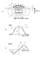
図9は、実施例2における磁場を説明する図である。
本実施例でも、実施例1と同様、縦磁場とは磁石と磁気検知部が離間する方向を縦磁場として定義し、横磁場とは磁石と磁気検知部とが相対的に移動する方向を横磁場として定義する。図9において図3と同じものには同じ番号を付した。図9(A)において、301は磁石を、301aは着磁境界をそれぞれ示している。図9(A)の断面は、磁石と磁気検知部が相対的に移動する方向と磁石と磁気検知部が離間する方向とを含む平面で切断した断面である。本実施例では、磁石301は、磁気検知部と磁石との相対的な移動方向に直交する平面を極性境界面として、互いに逆極性を有する複数の着磁部を有する。本実施例では、1つの磁石301が着磁境界を持つが、2つの単極磁石を、方向を反対にして近接して並べて、磁気回路を構成してもよい。
FIG. 9 is a diagram illustrating the magnetic field in the second embodiment.
Also in the present embodiment, as in the first embodiment, the longitudinal magnetic field defines the direction in which the magnet and the magnetic detector are separated from each other as the longitudinal magnetic field, and the transverse magnetic field refers to the direction in which the magnet and the magnetic detector are relatively moved. Define as magnetic field. In FIG. 9, the same components as those in FIG. In FIG. 9A, 301 indicates a magnet, and 301a indicates a magnetization boundary. The cross section of FIG. 9A is a cross section cut along a plane including a direction in which the magnet and the magnetic detection unit relatively move and a direction in which the magnet and the magnetic detection unit are separated from each other. In the present embodiment, the
図9(A)の紙面垂直方向には、所定の長さだけ磁石が延在しており、紙面垂直方向の組み立て誤差に対して頑健な構成となっている。図9(A)に示すように、磁界強度を示すベクトルは、磁気検知部が存在する平面内で、長さと角度を変えながら矢印15のように検出される。すなわち、磁石301の中央付近でベクトルは移動方向と平行になり、1つの着磁領域の中央付近でベクトル方向は離間方向に平行になり、さらに端部に行くと再び傾く。
In the direction perpendicular to the plane of the paper in FIG. 9A, the magnet extends for a predetermined length, which is robust against assembly errors in the direction perpendicular to the plane of the paper. As shown in FIG. 9A, the vector indicating the magnetic field strength is detected as indicated by an
図9(B)および図9(C)は、それぞれ、移動方向の位置に対する縦磁場と横磁場の磁界強度を示す。横軸は、移動方向の位置を示す。縦軸は、磁界強度を示す。図9(B)の311,312,313で示す磁界強度は、それぞれ、図9(A)の平面11,12,13と対応している。また、図9(C)の321,322,323で示す磁界強度も、それぞれ、図9(A)の平面11,12,13と対応している。
FIG. 9B and FIG. 9C show the magnetic field strengths of the longitudinal magnetic field and the transverse magnetic field with respect to the position in the moving direction, respectively. The horizontal axis indicates the position in the movement direction. The vertical axis represents the magnetic field strength. Magnetic field strengths indicated by 311, 312, and 313 in FIG. 9B correspond to the
図9(B)および図9(C)の横軸は移動方向の位置を示しており、縦軸との交点は磁石中心を示している。図9(B)に示すように、縦磁場の磁界強度は磁石中心でゼロとなるS字型の曲線である。また、検知平面11,12,13での磁界強度の曲線311,312,313が示すように、極大値および極小値は、磁石に近い位置で検知したほうが大きいという傾向を示す。 9B and 9C, the horizontal axis indicates the position in the movement direction, and the intersection with the vertical axis indicates the magnet center. As shown in FIG. 9B, the magnetic field intensity of the longitudinal magnetic field is an S-shaped curve that becomes zero at the magnet center. Further, as indicated by the magnetic field intensity curves 311, 312, and 313 on the detection planes 11, 12, and 13, the maximum value and the minimum value tend to be larger when detected at positions close to the magnet.
図9(C)に示すように、横磁場は軸対称の曲線であり、磁界強度は、磁石中心で極値を持ち、さらに少し離れた位置で極値をもつ曲線である。また、検知平面11,12,13での磁界強度の曲線321,322,323が示すように、磁石に近い位置で検知したほうが、ピーク強度が強いという傾向を示す。従来の防振機構においては、縦磁場検知のみを用いて位置検出をしている。すなわち、図9(B)のS字型の関数のうち、移動方向の位置に関して原点近傍での直線性の高い個所を利用している。この方法では検知範囲が狭い、誤差に頑健ではないという課題がある。 As shown in FIG. 9C, the transverse magnetic field is an axisymmetric curve, and the magnetic field strength is a curve having an extreme value at the magnet center and having an extreme value at a slightly further position. Further, as shown by the magnetic field intensity curves 321, 322, and 323 on the detection planes 11, 12, and 13, the peak intensity tends to be stronger when the detection is performed at a position closer to the magnet. In the conventional anti-vibration mechanism, position detection is performed using only longitudinal magnetic field detection. That is, in the S-shaped function of FIG. 9B, a portion having high linearity near the origin with respect to the position in the movement direction is used. This method has a problem that the detection range is narrow and the error is not robust.
図10は、実施例2の位置検出装置の構成と出力とを説明する図である。
図10(A)は、位置検出装置が備える磁石と磁気検知部の配置を示す。図10において図2と同じ機能のものには同じ番号を付した。301は磁石を示す。素子2aは、縦磁場検知部3vおよび横磁場検知部3hを内部に包含しており、本実施例の磁気検知部である。検知部は素子2aの中央付近にあり、離間方向に縦磁場検知部と横磁場検知部が積層して形成されている。磁石301と素子2aは図10(A)の紙面横方向に相対的に移動可能としている。この例では、素子2aを固定するが、相対的に移動できればよく、磁石301を固定して素子2aを移動させてもよい。また、磁石301と素子2aとの相対的移動は離間方向の間隔を一定に保って行われるように案内されている。
FIG. 10 is a diagram illustrating the configuration and output of the position detection device according to the second embodiment.
FIG. 10A shows the arrangement of magnets and magnetic detection units provided in the position detection device. In FIG. 10, the same functions as those in FIG.
図10(B)は、位置検出装置における信号の流れを示す。素子2aに備えられた縦磁場検知部3vおよび横磁場検知部3hから得られた信号がA/D変換器4に入力される。A/D変換器4が、入力された信号をデジタル信号に変換し、演算器5に入力する。演算器5は、入力された信号に基づいて、以下に示す(式7)または(式8)を用いて演算し、出力信号を出力する。
(出力信号)=(縦磁場強度)/(横磁場強度)・・・(式7)
(出力信号)=tan-1{(縦磁場強度)/(横磁場強度)}・・・(式8)
FIG. 10B shows a signal flow in the position detection device. Signals obtained from the longitudinal
(Output signal) = (longitudinal magnetic field strength) / (lateral magnetic field strength) (Expression 7)
(Output signal) = tan −1 {(longitudinal magnetic field strength) / (transverse magnetic field strength)} (Equation 8)
(式7)および(式8)と、前述した(式5)および(式6)との違いは、縦磁場と横磁場を分母と分子で逆転させたことのみである。信号の特性やいずれを用いれば良いかという判断も実施例1と同様のため説明を割愛し、以下では(式7)を用いた演算結果と、縦磁場を出力する従来技術との比較を行う。 The difference between (Expression 7) and (Expression 8) and the above-described (Expression 5) and (Expression 6) is only that the longitudinal magnetic field and the transverse magnetic field are reversed between the denominator and the numerator. Since the characteristics of the signal and which one should be used are also the same as in the first embodiment, the description thereof will be omitted. In the following, the calculation result using (Equation 7) is compared with the prior art that outputs the longitudinal magnetic field. .
図10(C)は、実施例2の位置検出装置が備える演算器5の出力を示す。図10(D)は、従来の位置検出装置の出力を示す。図10(C),(D)において、横軸は、図2と同じスケールの移動方向の位置を示す。縦軸は、演算器の出力を示す。図10(C)の331,332,333、図10(D)の341,342,343は、この順に磁石と磁気検知部が近い場合の演算結果を示す。
FIG. 10C shows the output of the
図10(C)の3つの関数331,332,333の方が、図10(D)の3つの関数341,342,343よりも近接しており、離間方向の距離変動に対して頑健であることが分かる。本実施例の演算では、離間方向の距離の変動に頑健であるので、温度にも頑健である。以上説明した実施例2によれば、簡単な構成で組み立て誤差、環境による変化に対して頑健な位置検出装置を提供することができる。
The three
(その他の実施例)
本発明は、上述の実施例の1以上の機能を実現するプログラムを、ネットワーク又は記憶媒体を介してシステム又は装置に供給し、そのシステム又は装置のコンピュータにおける1つ以上のプロセッサーがプログラムを読出し実行する処理でも実現可能である。また、1以上の機能を実現する回路(例えば、ASIC)によっても実現可能である。
(Other examples)
The present invention supplies a program that realizes one or more functions of the above-described embodiments to a system or apparatus via a network or a storage medium, and one or more processors in a computer of the system or apparatus read and execute the program This process can be realized. It can also be realized by a circuit (for example, ASIC) that realizes one or more functions.
1 磁石
2a 磁気検知部
3a 縦磁場検知部
3b 横磁場検知部
4 A/D変換器
5 演算器
301 磁石
301a 着磁境界
DESCRIPTION OF
Claims (11)
磁石と、
レンズを保持する保持体を通電により移動させるコイルと、
前記保持体の位置を検知する位置検出信号を演算する演算部と、を備え、
前記磁石と前記磁気検知部とは、所定間隔を保って相対的に移動可能であり、
前記磁気検知部は、前記磁気検知部と前記磁石との離間方向の磁場を検知する第1の磁場検知部と、前記磁石の移動方向の磁場を検知する第2の磁場検知部とを有し、
前記磁石は、前記移動方向において逆極性の2つの着磁部が並び、
前記移動方向と前記離間方向を含む平面で切断された断面内において、前記コイルは、離間した第1の領域、第2の領域の2つに分断されており、
前記移動方向において、前記コイルの第1の領域は、前記磁石の2つの着磁部の一方と対向し、前記コイルの第2の領域は、前記磁石の2つの着磁部の他方と対向し、
前記演算部は、前記第2の磁場検知部の信号と前記第1の磁場検知部の信号とに基づいて前記位置検出信号を演算する
ことを特徴とする撮像装置。 A magnetic detector;
A magnet,
A coil that moves the holding body holding the lens by energization;
And a calculator for calculating a position detection signal for detecting a position of the holding member,
The magnet and the magnetic detection unit are relatively movable with a predetermined interval,
The magnetic detection unit includes a first magnetic field detection unit that detects a magnetic field in a separation direction between the magnetic detection unit and the magnet, and a second magnetic field detection unit that detects a magnetic field in the movement direction of the magnet. ,
In the magnet, two magnetized portions having opposite polarities in the moving direction are arranged,
In a cross section cut by a plane including the moving direction and the separation direction, the coil is divided into two parts, a first region and a second region,
In the moving direction, the first region of the coil faces one of the two magnetized portions of the magnet, and the second region of the coil faces the other of the two magnetized portions of the magnet. ,
The said calculating part calculates the said position detection signal based on the signal of the said 2nd magnetic field detection part, and the signal of the said 1st magnetic field detection part. The imaging device characterized by the above-mentioned.
ことを特徴とする請求項1に記載の撮像装置。 The magnet is composed of one magnet having a plurality of magnetized portions having opposite polarities with a plane perpendicular to the relative movement direction of the magnetic detection unit and the magnet as a polar boundary surface. The imaging apparatus according to claim 1.
ことを特徴とする請求項1に記載の撮像装置。The imaging apparatus according to claim 1.
ことを特徴とする請求項1に記載の撮像装置。 The calculation unit performs a calculation of dividing one of the signal of the second magnetic field detection unit and the signal of the first magnetic field detection unit by the other, or the signal of the second magnetic field detection unit and the signal The imaging apparatus according to claim 1, wherein calculation is performed using an arctangent function based on a signal from the first magnetic field detection unit.
ことを特徴とする請求項4に記載の撮像装置。 Whether the calculation unit calculates the position detection signal using either the calculation by the division or the calculation by the arctangent function according to the relative movement amount of the magnetism detection unit and the magnet. The imaging apparatus according to claim 4 , wherein switching is performed.
ことを特徴とする請求項4または5に記載の撮像装置。 The imaging apparatus according to claim 4 or 5 , wherein the calculation by the arctangent function uses the result of the division as a variable.
ことを特徴とする請求項6に記載の撮像装置。 A movement restricting member for restricting relative movement between the magnetism detection unit and the magnet so that the signal to be divided does not become half or less of the maximum value in the calculation by the division or the arctangent function. The imaging apparatus according to claim 6 .
ことを特徴とする請求項1に記載の撮像装置。The imaging apparatus according to claim 1.
前記コイルは、前記磁石の前記第1面の裏側に位置する第2面に対向して配置されるThe coil is disposed to face a second surface located on the back side of the first surface of the magnet.
ことを特徴とする請求項1に記載の撮像装置。The imaging apparatus according to claim 1.
前記磁気検知部は、前記磁気検知部と前記磁石との離間方向の磁場を検知する第1の磁場検知部と、前記磁石の移動方向の磁場を検知する第2の磁場検知部とを有し、
前記磁石は、前記移動方向において逆極性の2つの着磁部が並び、
前記移動方向と前記離間方向を含む平面で切断された断面内において、前記コイルは、離間した第1の領域、第2の領域の2つに分断されており、
前記移動方向において、前記コイルの第1の領域は、前記磁石の2つの着磁部の一方と対向し、前記コイルの第2の領域は、前記磁石の2つの着磁部の他方と対向し、
前記第2の磁場検知部の信号と前記第1の磁場検知部の信号とに基づいて前記保持体の位置を検知する位置検出信号を演算する工程を有する
ことを特徴とする制御方法。 A control method of an imaging apparatus comprising: a magnetic detection unit and a magnet that are relatively movable at a predetermined interval ; and a coil that moves a holding body that holds a lens by energization ,
The magnetic detection unit includes a first magnetic field detection unit that detects a magnetic field in a separation direction between the magnetic detection unit and the magnet, and a second magnetic field detection unit that detects a magnetic field in the movement direction of the magnet. ,
In the magnet, two magnetized portions having opposite polarities in the moving direction are arranged,
In a cross section cut by a plane including the moving direction and the separation direction, the coil is divided into two parts, a first region and a second region,
In the moving direction, the first region of the coil faces one of the two magnetized portions of the magnet, and the second region of the coil faces the other of the two magnetized portions of the magnet. ,
A control method comprising: calculating a position detection signal for detecting the position of the holding body based on the signal of the second magnetic field detection unit and the signal of the first magnetic field detection unit.
A program causing a computer to execute the control method according to claim 10 .
Priority Applications (2)
| Application Number | Priority Date | Filing Date | Title |
|---|---|---|---|
| JP2015125234A JP6621253B2 (en) | 2015-06-23 | 2015-06-23 | Imaging apparatus, control method, and program |
| US15/189,585 US10701267B2 (en) | 2015-06-23 | 2016-06-22 | Position detection device, control method, and storage medium |
Applications Claiming Priority (1)
| Application Number | Priority Date | Filing Date | Title |
|---|---|---|---|
| JP2015125234A JP6621253B2 (en) | 2015-06-23 | 2015-06-23 | Imaging apparatus, control method, and program |
Publications (3)
| Publication Number | Publication Date |
|---|---|
| JP2017009443A JP2017009443A (en) | 2017-01-12 |
| JP2017009443A5 JP2017009443A5 (en) | 2018-07-26 |
| JP6621253B2 true JP6621253B2 (en) | 2019-12-18 |
Family
ID=57602037
Family Applications (1)
| Application Number | Title | Priority Date | Filing Date |
|---|---|---|---|
| JP2015125234A Active JP6621253B2 (en) | 2015-06-23 | 2015-06-23 | Imaging apparatus, control method, and program |
Country Status (2)
| Country | Link |
|---|---|
| US (1) | US10701267B2 (en) |
| JP (1) | JP6621253B2 (en) |
Families Citing this family (1)
| Publication number | Priority date | Publication date | Assignee | Title |
|---|---|---|---|---|
| JPWO2018012272A1 (en) * | 2016-07-12 | 2019-05-09 | パナソニックIpマネジメント株式会社 | Magnetic sensor and detection device using the same |
Family Cites Families (22)
| Publication number | Priority date | Publication date | Assignee | Title |
|---|---|---|---|---|
| DE10141764A1 (en) * | 2000-10-20 | 2002-06-27 | Micro Epsilon Messtechnik | Device and method for detecting the position of an object |
| EP1243897B1 (en) * | 2001-03-23 | 2013-12-18 | Melexis Technologies NV | Magnetic position sensor |
| JP4612281B2 (en) | 2003-03-25 | 2011-01-12 | 旭化成エレクトロニクス株式会社 | Position detection device |
| JP4587708B2 (en) * | 2004-05-20 | 2010-11-24 | コニカミノルタオプト株式会社 | Position detection device, camera shake correction mechanism, and imaging device |
| JP2006047228A (en) * | 2004-08-06 | 2006-02-16 | Tokai Rika Co Ltd | Rotation angle detecting device |
| JP4400500B2 (en) * | 2005-04-06 | 2010-01-20 | コニカミノルタオプト株式会社 | Position detector and positioning device |
| KR101438233B1 (en) * | 2005-10-25 | 2014-09-05 | 가부시키가이샤 니콘 | Position detecting apparatus and optical device |
| JP4968885B2 (en) * | 2006-06-05 | 2012-07-04 | キヤノン株式会社 | IMAGING DEVICE AND ITS CONTROL METHOD, IMAGING SYSTEM, IMAGE PROCESSING METHOD, AND PROGRAM |
| JP4273363B2 (en) * | 2006-11-21 | 2009-06-03 | 日立金属株式会社 | Rotation angle detection device, rotator, and rotation angle detection method |
| JP2008128962A (en) * | 2006-11-24 | 2008-06-05 | Alps Electric Co Ltd | Absolute angle detector |
| US7915886B2 (en) * | 2007-01-29 | 2011-03-29 | Honeywell International Inc. | Magnetic speed, direction, and/or movement extent sensor |
| JP2008241345A (en) * | 2007-03-26 | 2008-10-09 | Toshiba Mach Co Ltd | Phase detector and position detector |
| JP2008261786A (en) * | 2007-04-13 | 2008-10-30 | Alps Electric Co Ltd | Absolute angle detector |
| JP4853496B2 (en) * | 2007-07-30 | 2012-01-11 | 株式会社デンソー | Position detection sensor |
| JP2010038765A (en) * | 2008-08-06 | 2010-02-18 | Tokai Rika Co Ltd | Rotation detector |
| JP2010204242A (en) * | 2009-03-02 | 2010-09-16 | Fujifilm Corp | Driving device, shutter device for camera, and imaging device |
| JP5348235B2 (en) * | 2009-08-21 | 2013-11-20 | ミツミ電機株式会社 | Lens holder driving device and camera equipped with the same |
| US9222993B2 (en) * | 2010-07-30 | 2015-12-29 | Mitsubishi Electric Corporation | Magnetic substance detection device |
| JP2012208112A (en) * | 2011-03-11 | 2012-10-25 | Alps Electric Co Ltd | Position sensor, magnet member and manufacturing method for magnet member |
| JP2013003524A (en) * | 2011-06-21 | 2013-01-07 | Canon Inc | Image blur correction device and optical equipment using the same |
| DE102012220139A1 (en) * | 2012-11-06 | 2014-05-08 | Robert Bosch Gmbh | Magnetic measuring arrangement and corresponding sensor arrangement for detecting the movement of a moving component |
| JP6049570B2 (en) * | 2013-08-27 | 2016-12-21 | アルプス電気株式会社 | Rotation detector |
-
2015
- 2015-06-23 JP JP2015125234A patent/JP6621253B2/en active Active
-
2016
- 2016-06-22 US US15/189,585 patent/US10701267B2/en active Active
Also Published As
| Publication number | Publication date |
|---|---|
| US10701267B2 (en) | 2020-06-30 |
| US20160377453A1 (en) | 2016-12-29 |
| JP2017009443A (en) | 2017-01-12 |
Similar Documents
| Publication | Publication Date | Title |
|---|---|---|
| US10819909B2 (en) | Driving apparatus capable of satisfactorily detecting position of movable unit and ensuring large driving thrust, image blur correction apparatus, and image pickup apparatus | |
| JP4589410B2 (en) | Position detection device | |
| US7539404B2 (en) | Camera with vibration-proofing device that includes movable and fixed member with pin-shaped support member between them with curved surfaces | |
| JP4899712B2 (en) | Lens barrel | |
| US9436017B2 (en) | Image stabilizing apparatus that corrects image blur caused by hand shake, lens barrel, and optical apparatus | |
| JP6769696B2 (en) | Position detector | |
| WO2007049639A1 (en) | Position detecting apparatus and optical device | |
| US10757334B2 (en) | Actuator of camera module | |
| US9030741B2 (en) | Image stabilizing apparatus, lens barrel, and optical apparatus | |
| US20200158793A1 (en) | Apparatus for operating optical-reflector and apparatus and method for controlling position of optical-reflector | |
| JP2007156062A (en) | Parallel displacement device and actuator equipped therewith, lens unit and camera | |
| JP4926626B2 (en) | POSITION DETECTION SYSTEM, OPTICAL SYSTEM USING POSITION DETECTION SYSTEM, AND IMAGING DEVICE | |
| JP6621253B2 (en) | Imaging apparatus, control method, and program | |
| JP2006047054A (en) | Position detecting device, blurring correction device, and imaging device | |
| CN107561820B (en) | Actuator, and lens unit and camera provided with same | |
| US11265482B2 (en) | Position detecting device of aperture module | |
| JP2016133371A (en) | Magnetic position detection device, drive device, and optical apparatus | |
| JP4951801B2 (en) | Actuator, lens unit and camera equipped with the same | |
| US10416411B2 (en) | Optical apparatus | |
| JP2016157031A (en) | Lens driving device | |
| KR20150087611A (en) | Camera module and method for auto focus thereof | |
| CN110709767B (en) | Actuator, and lens unit and camera including the same | |
| JP2010266739A (en) | Vibration proof actuator and lens unit comprising the same and camera | |
| JP2009058329A (en) | Magnetization yoke, magnet magnetization method, magnet, position detection device, and deflection correction device | |
| JP2008292902A (en) | Image blur correction device and imaging device |
Legal Events
| Date | Code | Title | Description |
|---|---|---|---|
| A521 | Request for written amendment filed |
Free format text: JAPANESE INTERMEDIATE CODE: A523 Effective date: 20180615 |
|
| A621 | Written request for application examination |
Free format text: JAPANESE INTERMEDIATE CODE: A621 Effective date: 20180615 |
|
| A977 | Report on retrieval |
Free format text: JAPANESE INTERMEDIATE CODE: A971007 Effective date: 20190313 |
|
| A131 | Notification of reasons for refusal |
Free format text: JAPANESE INTERMEDIATE CODE: A131 Effective date: 20190402 |
|
| A521 | Request for written amendment filed |
Free format text: JAPANESE INTERMEDIATE CODE: A523 Effective date: 20190528 |
|
| TRDD | Decision of grant or rejection written | ||
| A01 | Written decision to grant a patent or to grant a registration (utility model) |
Free format text: JAPANESE INTERMEDIATE CODE: A01 Effective date: 20191021 |
|
| A61 | First payment of annual fees (during grant procedure) |
Free format text: JAPANESE INTERMEDIATE CODE: A61 Effective date: 20191119 |
|
| R151 | Written notification of patent or utility model registration |
Ref document number: 6621253 Country of ref document: JP Free format text: JAPANESE INTERMEDIATE CODE: R151 |