JP6598063B2 - Battery module - Google Patents
Battery module Download PDFInfo
- Publication number
- JP6598063B2 JP6598063B2 JP2015191858A JP2015191858A JP6598063B2 JP 6598063 B2 JP6598063 B2 JP 6598063B2 JP 2015191858 A JP2015191858 A JP 2015191858A JP 2015191858 A JP2015191858 A JP 2015191858A JP 6598063 B2 JP6598063 B2 JP 6598063B2
- Authority
- JP
- Japan
- Prior art keywords
- case
- battery
- battery module
- module
- laminate
- Prior art date
- Legal status (The legal status is an assumption and is not a legal conclusion. Google has not performed a legal analysis and makes no representation as to the accuracy of the status listed.)
- Active
Links
- 238000007789 sealing Methods 0.000 claims description 108
- 238000005192 partition Methods 0.000 claims description 38
- 239000005001 laminate film Substances 0.000 claims description 22
- 230000005484 gravity Effects 0.000 claims description 15
- 229910052751 metal Inorganic materials 0.000 claims description 14
- 239000002184 metal Substances 0.000 claims description 14
- 238000010248 power generation Methods 0.000 claims description 9
- 239000010410 layer Substances 0.000 description 11
- 239000000203 mixture Substances 0.000 description 9
- 239000002131 composite material Substances 0.000 description 5
- 239000010408 film Substances 0.000 description 5
- 229910052782 aluminium Inorganic materials 0.000 description 4
- 239000003125 aqueous solvent Substances 0.000 description 4
- 239000011230 binding agent Substances 0.000 description 4
- 230000006866 deterioration Effects 0.000 description 4
- 239000007773 negative electrode material Substances 0.000 description 4
- 239000011347 resin Substances 0.000 description 4
- 229920005989 resin Polymers 0.000 description 4
- WHXSMMKQMYFTQS-UHFFFAOYSA-N Lithium Chemical compound [Li] WHXSMMKQMYFTQS-UHFFFAOYSA-N 0.000 description 3
- 239000000853 adhesive Substances 0.000 description 3
- 230000001070 adhesive effect Effects 0.000 description 3
- XAGFODPZIPBFFR-UHFFFAOYSA-N aluminium Chemical compound [Al] XAGFODPZIPBFFR-UHFFFAOYSA-N 0.000 description 3
- 239000003792 electrolyte Substances 0.000 description 3
- 229910052744 lithium Inorganic materials 0.000 description 3
- 239000000463 material Substances 0.000 description 3
- 239000011255 nonaqueous electrolyte Substances 0.000 description 3
- 239000007774 positive electrode material Substances 0.000 description 3
- 238000010008 shearing Methods 0.000 description 3
- 150000003377 silicon compounds Chemical class 0.000 description 3
- 238000003466 welding Methods 0.000 description 3
- OKTJSMMVPCPJKN-UHFFFAOYSA-N Carbon Chemical compound [C] OKTJSMMVPCPJKN-UHFFFAOYSA-N 0.000 description 2
- 230000004308 accommodation Effects 0.000 description 2
- 239000011888 foil Substances 0.000 description 2
- 229910002804 graphite Inorganic materials 0.000 description 2
- 239000010439 graphite Substances 0.000 description 2
- 230000004048 modification Effects 0.000 description 2
- 238000012986 modification Methods 0.000 description 2
- 150000003839 salts Chemical class 0.000 description 2
- 239000002002 slurry Substances 0.000 description 2
- 239000002344 surface layer Substances 0.000 description 2
- RYGMFSIKBFXOCR-UHFFFAOYSA-N Copper Chemical compound [Cu] RYGMFSIKBFXOCR-UHFFFAOYSA-N 0.000 description 1
- PXGOKWXKJXAPGV-UHFFFAOYSA-N Fluorine Chemical compound FF PXGOKWXKJXAPGV-UHFFFAOYSA-N 0.000 description 1
- UFHFLCQGNIYNRP-UHFFFAOYSA-N Hydrogen Chemical compound [H][H] UFHFLCQGNIYNRP-UHFFFAOYSA-N 0.000 description 1
- HBBGRARXTFLTSG-UHFFFAOYSA-N Lithium ion Chemical compound [Li+] HBBGRARXTFLTSG-UHFFFAOYSA-N 0.000 description 1
- 229910018058 Ni-Co-Al Inorganic materials 0.000 description 1
- 229910018060 Ni-Co-Mn Inorganic materials 0.000 description 1
- 229910018144 Ni—Co—Al Inorganic materials 0.000 description 1
- 229910018209 Ni—Co—Mn Inorganic materials 0.000 description 1
- VYPSYNLAJGMNEJ-UHFFFAOYSA-N Silicium dioxide Chemical compound O=[Si]=O VYPSYNLAJGMNEJ-UHFFFAOYSA-N 0.000 description 1
- 239000000956 alloy Substances 0.000 description 1
- 229910045601 alloy Inorganic materials 0.000 description 1
- 150000001408 amides Chemical class 0.000 description 1
- 239000003575 carbonaceous material Substances 0.000 description 1
- 239000011248 coating agent Substances 0.000 description 1
- 238000000576 coating method Methods 0.000 description 1
- 239000004020 conductor Substances 0.000 description 1
- 239000000470 constituent Substances 0.000 description 1
- 229910052802 copper Inorganic materials 0.000 description 1
- 239000010949 copper Substances 0.000 description 1
- 238000001035 drying Methods 0.000 description 1
- 150000002148 esters Chemical class 0.000 description 1
- 150000002170 ethers Chemical class 0.000 description 1
- 238000010304 firing Methods 0.000 description 1
- 229910052731 fluorine Inorganic materials 0.000 description 1
- 239000011737 fluorine Substances 0.000 description 1
- 125000005843 halogen group Chemical group 0.000 description 1
- 229910052739 hydrogen Inorganic materials 0.000 description 1
- 239000001257 hydrogen Substances 0.000 description 1
- 238000009413 insulation Methods 0.000 description 1
- 239000011244 liquid electrolyte Substances 0.000 description 1
- 229910001416 lithium ion Inorganic materials 0.000 description 1
- 229910003002 lithium salt Inorganic materials 0.000 description 1
- 159000000002 lithium salts Chemical group 0.000 description 1
- 230000007774 longterm Effects 0.000 description 1
- 239000007769 metal material Substances 0.000 description 1
- 238000000034 method Methods 0.000 description 1
- 239000012046 mixed solvent Substances 0.000 description 1
- 229910052759 nickel Inorganic materials 0.000 description 1
- 150000002825 nitriles Chemical class 0.000 description 1
- 230000000149 penetrating effect Effects 0.000 description 1
- 229920000642 polymer Polymers 0.000 description 1
- 238000005096 rolling process Methods 0.000 description 1
- 239000010703 silicon Substances 0.000 description 1
- 229910052710 silicon Inorganic materials 0.000 description 1
- LIVNPJMFVYWSIS-UHFFFAOYSA-N silicon monoxide Chemical compound [Si-]#[O+] LIVNPJMFVYWSIS-UHFFFAOYSA-N 0.000 description 1
- 229910052814 silicon oxide Inorganic materials 0.000 description 1
- 239000007784 solid electrolyte Substances 0.000 description 1
- 239000002904 solvent Substances 0.000 description 1
- 238000000638 solvent extraction Methods 0.000 description 1
- 239000000725 suspension Substances 0.000 description 1
- 239000010409 thin film Substances 0.000 description 1
Images


Classifications
-
- Y—GENERAL TAGGING OF NEW TECHNOLOGICAL DEVELOPMENTS; GENERAL TAGGING OF CROSS-SECTIONAL TECHNOLOGIES SPANNING OVER SEVERAL SECTIONS OF THE IPC; TECHNICAL SUBJECTS COVERED BY FORMER USPC CROSS-REFERENCE ART COLLECTIONS [XRACs] AND DIGESTS
- Y02—TECHNOLOGIES OR APPLICATIONS FOR MITIGATION OR ADAPTATION AGAINST CLIMATE CHANGE
- Y02E—REDUCTION OF GREENHOUSE GAS [GHG] EMISSIONS, RELATED TO ENERGY GENERATION, TRANSMISSION OR DISTRIBUTION
- Y02E60/00—Enabling technologies; Technologies with a potential or indirect contribution to GHG emissions mitigation
- Y02E60/10—Energy storage using batteries
Landscapes
- Secondary Cells (AREA)
- Battery Mounting, Suspending (AREA)
Description
本開示は、電池モジュールに関する。 The present disclosure relates to a battery module.
従来、例えば特許文献1には、ラミネートケース電池を立てた状態で配置し、ラミネートケースの周囲に形成されている封止部のうち、正極および負極の各端子が引き出されている上方封止部を除く、両側の側方封止部および下方封止部を拘束して支持する構成が記載されている(特許文献1の図7参照)。
Conventionally, for example,
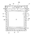
図7に示すように、ラミネートケース電池100は、一般に、ラミネートケース111内に図示しない発電要素(正極電極、負極電極、セパレータ、電解質等)を収容して構成される。ラミネートケース111は、収容部112と、その収容部112の周囲に形成された封止部114とを有する。収容部112には、上記発電要素を収容するための空間が内部に形成されている。
As shown in FIG. 7, the
封止部114は、収容部112の周囲においてラミネートフィルム同士を例えばヒートシール(または熱溶着)によって接合して形成されている。ラミネートケース111は、平面視で例えば長方形状をなし、収容部112の四方周囲に上方封止部114a、側方封止部114b,114c、および、下方封止部114dが形成されている。
図7において、ラミネートケース電池100は、枠体115により収容部112の周囲の四辺の封止部114を固定した状態が示されている。
The sealing
In FIG. 7, the laminated
上方封止部114aには、内部の発電要素に含まれる正極電極および負極電極にそれぞれ電気的に接続された正極端子116および負極端子118が引き出されている。正極端子116および負極端子118の周囲は、上方封止部114aにおいて液密状に封止されている。
A
このようなラミネートケース電池100を立てた状態に配置して、上記特許文献1に記載されるように両側の側方封止部114b,114cと下方封止部114dとを拘束して支持すると、ラミネートケース111を構成するラミネートフィルムに対して発電要素の自重が引張力、せん断力および圧縮力として作用する。より詳しくは、側方封止部114b,114cと収容部112との境界近傍に位置するラミネートフィルムの側方部分113b,113cにはせん断力が、下方封止部114dと収容部12との境界近傍に位置するラミネートフィルムの下方部分113dには圧縮力がそれぞれ作用する。
When such a laminated
このような支持状態では長期経過によって、収容部112を構成するラミネートフィルムの側方部分113b,113cおよび下方部分13dがせん断力および圧縮力がそれぞれ作用し続けることよって劣化しやすい。特に、ラミネートケース電池100が車両等に搭載される場合に振動が加わることによってその劣化度はより大きくなる。
In such a support state, the
本開示に係るラミネートケース電池は、発電要素を収容した収容部と該収容部の周囲に形成された封止部とを有するラミネートケース電池を縦置き状態でモジュールケース内に複数格納した電池モジュールであって、各ラミネートケース電池は、封止部のうち上方封止部で重力方向に支持され、かつ、上方封止部以外の封止部では重力方向に支持されていないものである。 A laminate case battery according to the present disclosure is a battery module in which a plurality of laminate case batteries each having a housing portion that houses a power generation element and a sealing portion formed around the housing portion are stored in a module case in a vertically placed state. Each laminated case battery is supported in the gravity direction by the upper sealing portion of the sealing portions, and is not supported in the gravity direction by the sealing portions other than the upper sealing portion.
本開示に係るラミネートケース電池によれば、ラミネートケースを構成するラミネートフィルムの側方部分および下方部分の劣化を抑制できる。 According to the laminate case battery according to the present disclosure, it is possible to suppress the deterioration of the side portion and the lower portion of the laminate film constituting the laminate case.
以下に、本発明に係る実施の形態(以下、実施形態という)について添付図面を参照しながら詳細に説明する。この説明において、具体的な形状、材料、数値、方向等は、本発明の理解を容易にするための例示であって、用途、目的、仕様等にあわせて適宜変更することができる。また、以下において複数の実施形態や変形例などが含まれる場合、それらの特徴部分を適宜に組み合わせて用いることは当初から想定されている。 DESCRIPTION OF EMBODIMENTS Hereinafter, embodiments according to the present invention (hereinafter referred to as embodiments) will be described in detail with reference to the accompanying drawings. In this description, specific shapes, materials, numerical values, directions, and the like are examples for facilitating the understanding of the present invention, and can be appropriately changed according to the application, purpose, specification, and the like. In addition, when a plurality of embodiments and modifications are included in the following, it is assumed from the beginning that these characteristic portions are used in appropriate combinations.
(第1実施形態)
図1は、第1実施形態の電池モジュール10の縦方向断面図である。図2は、図1中のA−A線断面図である。さらに、図3は、第1実施形態の電池モジュール10において用いられるラミネートケース電池2を示す正面図である。
(First embodiment)
FIG. 1 is a longitudinal sectional view of the
図1に示すように、電池モジュール10は、モジュールケース20を備える。モジュールケース20は、複数のラミネートケース電池2を縦置き状態で格納する容器である。モジュールケース20は、樹脂製の筐体によって構成されるのが好適である。具体的には、モジュールケース20は、例えば、下方に底部22が形成され、上方が開口した直方体状の筐体24と、筐体24の上方開口を塞いで取り付けられる蓋26によって構成できる。筐体24および蓋26は、例えば樹脂によって形成されるのが好適であるが、これに限定されずアルミニウムやその合金などの金属によって形成されても良い。
As shown in FIG. 1, the
図2に示すように、筐体24の四方側壁のうち一対の対向する側壁24a,24bの内面上部には、段部25がそれぞれ形成されている。これらの段部25は、後述する支持ブロック30の両端を引っ掛けることによって支持する支持部を構成する。
As shown in FIG. 2,
図1ないし図3に示すように、電池モジュール10に用いられるラミネートケース電池2は、ラミネートケース11を備える。ラミネートケース11は、カップ形状に成型されたラミネートフィルム11aと、平面状をなすラミネートフィルム11bによって構成される。ラミネートフィルム11a,11bには、金属層の両面に樹脂層が形成されたフィルムを用いることが好ましい。これにより、ラミネートフィルム11a,11bは、その周辺部においてヒートシールが可能になっている。また、金属層は、例えばアルミニウムの薄膜層であり、水分等の透過を防ぐ機能を有する。
As shown in FIGS. 1 to 3, the
本実施形態では、ラミネートフィルム11aは、例えば絞り加工によって形成されて扁平直方体状の収容空間を有する収容部12を有する。これに対し、ラミネートフィルム11bは平面形状をなしている。そして、各ラミネートフィルム11a,11bは、収容部12の四方周囲の封止部14において互いにヒートシールされることによって接合される。
In the present embodiment, the
図2および図3に示すように、ラミネートケース11の封止部14には、上方封止部14a、側方封止部14b,14c、および下方封止部14dが含まれる。上方封止部14aには、収容部12から延びる正極端子16および負極端子18がラミネートケース11の外部に引き出されている。正極端子16および負極端子18の周囲は、それぞれ、上方封止部14aを構成する2枚のラミネートフィルム11a,11b同士が液密状となるように接合されている。
As shown in FIGS. 2 and 3, the sealing
また、上方封止部14aは、側方封止部14b,14cおよび下方封止部14dに比べて幅広に形成されるのが好適である。そして、上方封止部14aには、ラミネートケース電池2を吊下げ支持するための複数の貫通孔15が形成されている。本実施形態では、3つの貫通孔15が形成された例が示される。このように貫通孔15が形成された上方封止部14aを比較的幅広に形成することで、ラミネートケース電池2を吊下げ支持するために十分な強度を付与することが可能になる。ただし、この構成に限定されるものではなく、上方封止部14aは他の封止部14b,14c,14dと同等以下の幅であってもよい。
The
ラミネートケース11の収容部12内には、発電要素としての電極積層体および非水電解質(いずれも図示せず)が収容されている。電極積層体は、複数の単板セルが積層された状態で構成される。各単板セルは、正極及び負極がセパレータを介して重ね合された状態で構成される電池単位である。各単板セルの正極は、収容部12内において正極リードを介して正極端子16の端部に例えば超音波溶接等によってそれぞれ接続されている。また、各単板セルの負極は、収容部12内において負極リードを介して負極端子18の端部に例えば超音波溶接等によってそれぞれ接続されている。
In the
電極積層体に含まれる正極は、例えば正極集電体と、当該集電体上に形成された正極合材層とで構成される。正極集電体には、アルミニウムなどの正極の電位範囲で安定な金属の箔、当該金属を表層に配置したフィルム等を用いることができる。正極合材層は、正極活物質の他に、導電材及び結着材を含み、集電体の両面に形成されていることが好適である。正極は、例えば正極集電体上に正極活物質、結着材等を含む正極合材スラリーを塗布し、塗膜を乾燥させた後、圧延して正極合材層を集電体の両面に形成することにより作製できる。 The positive electrode included in the electrode laminate is composed of, for example, a positive electrode current collector and a positive electrode mixture layer formed on the current collector. As the positive electrode current collector, a metal foil that is stable in the potential range of the positive electrode such as aluminum, a film in which the metal is disposed on the surface layer, or the like can be used. The positive electrode mixture layer preferably includes a conductive material and a binder in addition to the positive electrode active material, and is formed on both surfaces of the current collector. For example, the positive electrode is coated with a positive electrode mixture slurry containing a positive electrode active material, a binder, etc. on the positive electrode current collector, dried, and then rolled to form a positive electrode mixture layer on both sides of the current collector. It can be manufactured by forming.
正極活物質には、例えばリチウム含有複合酸化物が用いられる。リチウム含有複合酸化物は、特に限定されないが、一般式Li1+xMaO2+b(式中、x+a=1、−0.2<x≦0.2、−0.1≦b≦0.1、Mは少なくともNi、Co、Mn、Alのいずれかを含む)で表される複合酸化物であることが好ましい。好適な複合酸化物の一例としては、Ni−Co−Mn系、Ni−Co−Al系のリチウム含有複合酸化物が挙げられる。 As the positive electrode active material, for example, a lithium-containing composite oxide is used. Lithium-containing composite oxide is not particularly limited, the general formula Li 1 + x M a O 2 + b ( where, x + a = 1, -0.2 <x ≦ 0.2, -0.1 ≦ b ≦ 0.1 and M are preferably composite oxides represented by at least any one of Ni, Co, Mn, and Al. As an example of a suitable composite oxide, a Ni-Co-Mn-based or Ni-Co-Al-based lithium-containing composite oxide can be given.
電極積層体に含まれる負極は、例えば負極集電体と、当該集電体上に形成された負極合材層とで構成される。負極集電体には、銅などの負極の電位範囲で安定な金属の箔、当該金属を表層に配置したフィルム等を用いることができる。負極合材層は、負極活物質の他に、結着材を含むことが好適である。負極は、例えば負極集電体上に負極活物質、結着材等を含む負極合材スラリーを塗布し、塗膜を乾燥させた後、圧延して負極合材層を集電体の両面に形成することにより作製できる。 The negative electrode contained in the electrode laminate is composed of, for example, a negative electrode current collector and a negative electrode mixture layer formed on the current collector. As the negative electrode current collector, a metal foil that is stable in the potential range of a negative electrode such as copper, a film in which the metal is disposed on the surface layer, or the like can be used. The negative electrode mixture layer preferably includes a binder in addition to the negative electrode active material. For example, the negative electrode is prepared by applying a negative electrode mixture slurry containing a negative electrode active material, a binder, etc. on a negative electrode current collector, drying the coating film, and rolling the negative electrode mixture layer on both sides of the current collector. It can be manufactured by forming.
負極活物質としては、リチウムイオンを吸蔵放出可能な材料であればよく、一般的には黒鉛が用いられる。負極活物質には、ケイ素、ケイ素化合物、又はこれらの混合物を用いてもよく、ケイ素化合物等と黒鉛等の炭素材料を併用してもよい。ケイ素化合物の好適な一例は、SiOx(0.5≦x≦1.5)で表されるケイ素酸化物である。 The negative electrode active material may be any material that can occlude and release lithium ions, and graphite is generally used. As the negative electrode active material, silicon, a silicon compound, or a mixture thereof may be used, and a silicon compound or the like and a carbon material such as graphite may be used in combination. A suitable example of the silicon compound is a silicon oxide represented by SiO x (0.5 ≦ x ≦ 1.5).
非水電解質は、非水溶媒と、非水溶媒に溶解した電解質塩とを含む。非水電解質は、液体電解質に限定されず、ゲル状ポリマー等を用いた固体電解質であってもよい。非水溶媒には、例えばエステル類、エーテル類、ニトリル類、アミド類、及びこれらの2種以上の混合溶媒等を用いることができる。非水溶媒は、これら溶媒の水素の少なくとも一部をフッ素等のハロゲン原子で置換したハロゲン置換体を含んでいてもよい。電解質塩は、リチウム塩であることが好ましい。 The non-aqueous electrolyte includes a non-aqueous solvent and an electrolyte salt dissolved in the non-aqueous solvent. The nonaqueous electrolyte is not limited to a liquid electrolyte, and may be a solid electrolyte using a gel polymer or the like. As the non-aqueous solvent, for example, esters, ethers, nitriles, amides, and a mixed solvent of two or more thereof can be used. The non-aqueous solvent may contain a halogen-substituted product in which at least a part of hydrogen in these solvents is substituted with a halogen atom such as fluorine. The electrolyte salt is preferably a lithium salt.
図1および図2に示すように、モジュールケース20内の複数のラミネートケース電池2は、縦置き状態に並べられて格納されている。具体的には、モジュールケース20が例えば水平面上に置かれたとき、ラミネートケース11を構成する平面状のラミネートフィルム11bが鉛直方向に沿った姿勢で収納されている。
As shown in FIGS. 1 and 2, the plurality of
また、各ラミネートケース電池2の上方封止部14aは、複数のブロック片30aから構成される支持ブロック30により支持されている。両端の各ブロック片30aにはそれぞれ内側に向かう力が両端の各ブロック片30aを押圧する機構により印加され、複数の各ブロック片30aをそれぞれ密着させる方向の力が印加される。各ラミネートケース電池2の上方封止部14aは、各ブロック片30a間に(本実施形態の場合、平板状の隔壁40と共に)介在されるため、隣接するブロック片30a同士により挟持されてラミネートケース電池2が吊下げ支持される。
Moreover, the
支持ブロック30の溝32には、ラミネートケース電池2の上方封止部14aと共に平板状の隔壁40の上端部が重ね合されて挿入されている。この場合、接着剤、両面テープ等による接着を併用することで、支持ブロック30の溝32にラミネートケース電池2の上方封止部14aを確実に固定することができる。
In the
支持ブロック30の溝32には、ラミネートケース電池2の正極端子16および負極端子18を挿通するための開口部34が形成されており、前記開口部34を介して正極端子16および負極端子18の上端部が支持ブロック30の上面から突出した状態になる。
In the
モジュールケース20内において、支持ブロック30の上面から突出した各ラミネートケース電池2の正極端子16同士が図示しない正極用バスバーを介して接続される。同様に、各ラミネートケース電池2の負極端子18同士が図示しない負極用バスバーを介して接続される。そして、正極用バスバーおよび負極用バスバーは、モジュールケース20の外部に引き出されるか、あるいは、モジュールケース20の壁部に固定される外部接続用コネクタに接続される。
In the
支持ブロック30には、複数の開口部34が形成されている。本実施形態では、ラミネートケース電池2の上方封止部14aに形成された貫通孔15に対応して、3つの貫通孔36が形成されている。また、各貫通孔36の形成位置は、支持ブロック30の溝32にラミネートケース電池2の上方封止部14aを挿入したときに、上方封止部14aに形成された貫通孔15と揃う位置に形成されている。さらに、各貫通孔36は、支持ブロック30の複数の溝32を貫通して延伸している。
A plurality of
そして、支持ブロック30の溝32にラミネートケース電池2の上方封止部14aが挿入された状態で、軸部材38が支持ブロック30の貫通孔36に挿通されている。これにより、各ラミネートケース電池2は、上方封止部14aの貫通孔15に軸部材38が挿通されることによって、支持ブロック30と一体に組み付けられる。
The
また、支持ブロック30の溝32内に上方封止部14aと一緒に挿入されている隔壁40の上端部にも軸部材38を挿通するための貫通孔が形成されている。したがって、本実施形態では、隔壁40は、支持ブロック30の溝32内に上端部がラミネートケース電池2の上方封止部14aと重なった状態で挿入された後に軸部材38が支持ブロック30の貫通孔36に軸部材38が挿通されることによって、ラミネートケース電池2と共に支持ブロック30と一体に組み付けられる。
A through hole for inserting the
軸部材38には、例えば金属製の棒材を用いることができる。この場合、軸部材38の両端に雌ねじ部を形成しておき、支持ブロック30の貫通孔36からそれぞれ突出した金属棒の雌ねじ部にナットを螺合させて締め付けることによって、支持ブロック30を構成する複数の各ブロック片30aをそれぞれ密着させる力を印加して各ラミネートケース電池2の上方封止部14aを各ブロック片30aにより挟持しても良い。軸部材38の両端にナットを螺合することによって同時に支持ブロック30から軸部材38が抜けないように固定してもよい。或いは、軸部材38として、金属棒材の外周が樹脂層で覆われたものを用いることにより軸部材38とラミネートケース11との絶縁を確実にしてもよい。
For example, a metal bar can be used for the
図1および図2に示すように、モジュールケース20の底部22には、固定部材42が設置されている。固定部材42には、隔壁40の下端部を嵌合するための凹部44が形成されている。このように隔壁40の下端部が固定部材42の凹部44に嵌合されることによって、モジュールケース20内において隔壁40の下端部の位置決めをすることができる。
As shown in FIGS. 1 and 2, a fixing
隔壁40は、上述したように各ラミネートケース電池2と共に支持ブロック30と一体に組付けられた後、モジュールケース20の筐体24内に上方開口から入れられる。このとき、固定部材42は、隔壁40の下端部を凹部44に嵌合した状態で例えば接着剤等で予め固定しておき、支持ブロック30およびラミネートケース電池2と一緒に筐体24内に入れるのが好ましい。この場合、固定部材42に接着剤、両面テープ等を予め付けておくことで、筐体24の底部22に固定することができる。
The
このようにしてモジュールケース20の筐体24内に入れられた支持ブロック30は、筐体24の対向する両側壁面に形成された段部25に引っ掛かって筐体24に支持される。この状態で、支持ブロック30は、接着、ねじ等の手法によって筐体24の側壁に固定されてもよい。これによって、各ラミネートケース電池2は、上方封止部14aに貫通した軸部材38によって吊下げられて重力方向に支持された状態になる。このとき、隔壁40は、上端部が支持ブロック30の溝32に挿入され、かつ、下端部が固定部材42の凹部44に挿入された状態で、位置決めされている。これにより、各隔壁40は互いに平行に配置され、隔壁40間には、ラミネートケース電池2の収容部12の厚みに略相当する幅Wの収容空間27が画定されている。本実施形態では、5つの収容空間27が隔壁40で仕切られて形成されており、各収容空間27にラミネートケース電池2がそれぞれ収容されている。
In this manner, the support block 30 placed in the
本実施形態では、モジュールケース20に格納されるラミネートケース電池2の数よりも1つ多い数の隔壁40が用いられる。具体的には、図1に示すように、5つのラミネートケース電池2に対して、6つの隔壁40が用いられる。図1中において最も右側に位置する支持ブロック30の溝32には、隔壁40の上端部だけが挿入されている。すなわち、本実施形態における支持ブロック30には、モジュールケース20内に格納されるラミネートケース電池2の数よりも1つ多い6つの溝32が形成されている。これにより、各隔壁40の間にラミネートケース電池2を収容するための5つの収容空間27が形成されている。
In the present embodiment, the number of
上記のようにラミネートケース電池2がモジュールケース20内に格納されたとき、ラミネートケース電池2において平面状のラミネートフィルム11bの表面全体が隔壁40に接触している。また、もう1枚のラミネートフィルム11aは、収容部12を構成する部分の表面が隔壁40に接触している。このようにラミネートケース電池2が両側で隔壁40に接触していることによって、上方封止部14aだけで重力方向に支持されたラミネートケース電池2が収容空間27内で揺動するのを防止できる。このことは、電池モジュール10が車両等に搭載されて使用される際に、特に有効である。また、対向する隔壁40によって各ラミネートケース電池2の収容部12を挟持して、ラミネートケース電池2の吊下げ支持を補助してもよい。
As described above, when the
隔壁40は、金属板で構成されるのが好ましい。金属板は、熱伝導性に優れるため、上記のようにラミネートケース電池2の両側表面に接触していることで、ラミネートケース電池2における温度ばらつきを解消するのに寄与できる。さらに、隔壁40は、高温耐熱性を有することが好適である。これにより、モジュールケース20内に格納された複数のラミネートケース電池2間での類焼を防止することが可能になる。
The
また、各隔壁40の下端部が嵌合されている固定部材42は、熱伝導性に優れた材料、例えば金属材料で形成されるのが好ましい。これにより、隔壁40および固定部材42を介して熱伝導させることによって、各ラミネートケース電池2間での温度ばらつきを抑制することができる。
Moreover, it is preferable that the fixing
図1および図2に示すように、上記のようにしてモジュールケース20内に格納されたラミネートケース電池2は、上方封止部14aが支持ブロック30および軸部材38によって重力方向に支持されているが、両側の側方封止部14b,14cは拘束も支持もされていない。下方封止部14dもまた、固定部材42の上方に位置して非接触となっており、拘束も支持もされていない。つまり、各ラミネートケース電池2は、上方封止部14aのみで重力方向に支持され、かつ、上方封止部14a以外の側方封止部14b,14cおよび下方封止部14dでは重力方向に支持されていない。したがって、モジュールケース20内に縦置き状態で格納されたラミネートケース電池2において、ラミネートケース11の側方封止部14a,14bと収容部12との境界近傍でラミネートフィルム11aにせん断力が作用するのを抑制または解消でき、さらに、ラミネートケース11の下方封止部14dと収容部12との境界近傍でラミネートフィルム11aに圧縮力が作用するのを抑制または解消できる。これらのことから、ラミネートケース11を構成するラミネートフィルム11a,11bの側方部分13b,13cおよび下方部分13dの劣化を抑制できる。
As shown in FIGS. 1 and 2, in the
(第2実施形態)
次に、図4〜図6を参照して、第2実施形態の電池モジュール10Aについて説明する。図4は、第2実施形態である電池モジュール10Aの縦方向断面図である。図5は、図4中のB−B線断面図である。また、図6は、第2実施形態で用いられる1つのラミネートケース電池2Aを示す平面図である。以下では、上述した第1実施形態の電池モジュール10と同一または類似の構成要素には同一または類似の符号を付して重複する説明を繰り返さない。
(Second Embodiment)
Next, with reference to FIGS. 4-6, 10A of battery modules of 2nd Embodiment are demonstrated. FIG. 4 is a longitudinal sectional view of a
図4〜図6に示すように、本実施形態の電池モジュール10Aでは、上方封止部14aが一対の挟持板50a,50bによって挟持されてラミネートケース電池2Aが吊下げ支持されている。一対の挟持板50a,50bは、各ラミネートケース電池2Aに対応してそれぞれ設けられている。本実施形態では、5つのラミネートケース電池2Aに対応して5対の挟持板50a,50bが設けられている。また、図4に示すように、最も外側に位置して隔壁40だけを支持する支持部材52が設けられている。これらの複数対の挟持板50a,50bおよび支持部材52には、複数の貫通孔36がそれぞれ形成されており、その貫通孔36に軸部材38が貫通して配置されている。図5に示すように、本実施本実施形態では、6個の貫通孔36が形成されている。
As shown in FIGS. 4 to 6, in the
本実施形態では、軸部材38はボルト(締結部材)54によって構成される。そして、ボルト54の先端に螺合させたナット(締結部材)56を締め付けることによって、各対の挟持板50a,50bによって上方封止部14aおよび隔壁40の上端部が溝32内で挟持される。これにより、複数対の挟持板50a,50b、隔壁40、ラミネートケース電池2Aおよび支持部材52が一体に連結される。
この場合、各対の挟持板50a,50b、や上方封止部14aおよび隔壁40の上端部に凹凸や係合部などを設けて摩擦力の向上を図り、上方封止部14aおよび隔壁40の上端部が各対の挟持板50a,50bによる挟持からより外れ難くすることも好適である。
In the present embodiment, the
In this case, the upper and
図5および図6に示すように、本実施形態では、軸部材38がラミネートケース11の上方封止部14aを通らない位置で複数対の挟持板50a,50bを貫通して設けられている。したがって、ラミネートケース電池2Aでは、上方封止部14aに貫通孔が形成されておらず、この点で第1実施形態におけるラミネートケース電池2と相違する。
As shown in FIG. 5 and FIG. 6, in this embodiment, the
複数対の挟持板50a,50bおよび軸部材38によって一体に連結された複数のラミネートケース電池2Aがモジュールケース20に入れられて段部25で支持されること、および、隔壁40の下端部がモジュールケース20の筐体24の底部22に設置される固定部材42の凹部に嵌合して位置決めされることは、上述した第1実施形態の場合と同様である。
A plurality of
上述したように本実施形態の電池モジュール10Aでは、各ラミネートケース電池2Aの上方封止部14aを一対の挟持板50a,50bで挟持した状態でモジュールケース20内において吊下げ支持される。この場合も、ラミネートケース電池2Aの側方封止部14b,14cおよび下方封止部14dは拘束も支持もされていない。つまり、各ラミネートケース電池2は、上方封止部14aのみで重力方向に支持され、かつ、上方封止部14a以外の側方封止部14b,14cおよび下方封止部14dでは重力方向に支持されていない。したがって、第1実施形態の場合と同様に、ラミネートケース11を構成するラミネートフィルム11a,11bの側方部分13b,13cおよび下方部分13dの劣化を抑制できる。
As described above, in the
なお、本発明は、上記実施形態およびその変形例に限定されるものではなく、本願の特許請求の範囲に記載された事項およびその均等な範囲において種々の改良や変更が可能である。 In addition, this invention is not limited to the said embodiment and its modification, A various improvement and change are possible in the matter described in the claim of this application, and its equivalent range.
例えば、上記においては、固定部材42を各ラミネートケース電池2,2Aの下方封止部14dに予め固定した状態でモジュールケース20の筐体24内に入れる場合について説明したが、これに限定されるものではない。固定部材42をモジュールケース20の筐体24の底部22上に先に設置して固定し、そこに支持ブロック30または複数対の挟持板50a,50bによって一体に連結された各ラミネートケース電池2,2Aの下方封止部14dを嵌合させるように組み付けてもよい。
For example, in the above description, the case where the fixing
また、上記においては、モジュールケース20の筐体24が上方に開口するものとして説明したが、これに限定されるものではなく、側方に開口する筐体を用いてもよいし、あるいは、上方および側方が開口する筐体と側端面がL字状をなす蓋とを用いてモジュールケースを構成してもよい。
In the above description, the
さらに、上記においては各ラミネートケース電池2,2Aが隔壁40によって仕切られた収容空間27内にそれぞれ収容される例について説明したが、これに限定されるものではなく、隔壁40を省略して共通の収容空間に複数のラミネートケース電池が互いに接触した状態あるいは僅かな隙間を空けた状態で吊下げ支持されるように構成してもよい。
Further, in the above description, an example in which each
2,2A ラミネートケース電池、10、10A 電池モジュール、11 ラミネートケース、11a,11b ラミネートフィルム、12 収容部、13b,13c 側方部分、13d 下方部分、14 封止部、14a 上方封止部、14b,14c 側方封止部、14d 下方封止部、15 貫通孔、16 正極端子、18 負極端子、20 モジュールケース、22 底部、24 筐体、24a,24b 側壁、25 段部、26 蓋、27 収容空間、30 支持ブロック、30a ブロック片、32 溝、34 開口部、36 貫通孔、38 軸部材、40 隔壁、42 固定部材、44 凹部、50a,50b 一対の挟持板、52 支持部材、54 ボルト、56 ナット、W 幅。 2,2A laminate case battery, 10, 10A battery module, 11 laminate case, 11a, 11b laminate film, 12 housing portion, 13b, 13c side portion, 13d lower portion, 14 sealing portion, 14a upper sealing portion, 14b , 14c Side sealing part, 14d Lower sealing part, 15 Through hole, 16 Positive terminal, 18 Negative terminal, 20 Module case, 22 Bottom part, 24 Housing, 24a, 24b Side wall, 25 Step part, 26 Lid, 27 Housing space, 30 support block, 30a block piece, 32 groove, 34 opening, 36 through hole, 38 shaft member, 40 partition wall, 42 fixing member, 44 recess, 50a, 50b a pair of clamping plates, 52 support member, 54 bolt , 56 Nut, W width.
Claims (10)
前記各ラミネートケース電池は、前記封止部のうち上方封止部で重力方向に支持され、かつ、前記上方封止部以外の封止部では重力方向に支持されていない、
電池モジュール。 A battery module in which a plurality of stored in the module case the laminate case battery vertically placed condition and a thinner sealing portion than Rutotomoni the receiving portion is formed around the housing portion and the container portion containing the power generating element,
Each of the laminate case batteries is supported in the gravitational direction by the upper sealing portion of the sealing portions, and is not supported in the gravitational direction by a sealing portion other than the upper sealing portion.
Battery module.
前記各ラミネートケース電池は、前記封止部のうち上方封止部で重力方向に支持され、かつ、前記上方封止部以外の封止部では重力方向に支持されておらず、
前記電池モジュールの上方封止部は少なくとも1つの支持ブロックの溝に挿入され、前記各電池モジュールは、前記支持ブロックを貫通して設けられる軸部材が前記溝内で前記上方封止部の貫通孔を通って延びており、前記支持ブロックが前記モジュールケースに支持されている、
電池モジュール。 A battery module in which a plurality of laminated case batteries having a housing part that houses a power generation element and a sealing part formed around the housing part are stored in a module case in a vertically placed state,
Each laminate case battery is supported in the gravity direction by the upper sealing portion of the sealing portions, and is not supported in the gravity direction by the sealing portions other than the upper sealing portion,
The upper sealing portion of the battery module is inserted into a groove of at least one support block, and each battery module has a shaft member provided through the support block in the groove. The support block is supported by the module case,
Battery module.
前記支持ブロックは、前記モジュールケース内に格納される複数のラミネートケース電池に対応した数の前記溝を少なくとも有する1つの部材である、電池モジュール。 The battery module according to claim 2,
The said support block is a battery module which is one member which has at least the said groove | channel of the number corresponding to the some laminated case battery accommodated in the said module case.
前記各ラミネートケース電池は、前記封止部のうち上方封止部で重力方向に支持され、かつ、前記上方封止部以外の封止部では重力方向に支持されておらず、
前記電池モジュールの上方封止部は一対の挟持板によって挟持され、前記一対の挟持板が前記モジュールケースに支持され、
前記一対の挟持板は、前記モジュールケースに格納される各ラミネートケース電池に対応してそれぞれ設けられ、かつ、前記ラミネートケース電池の上方封止部を通らない位置を貫通する締結部材によって一体に連結されている、
電池モジュール。 A battery module in which a plurality of laminated case batteries having a housing part that houses a power generation element and a sealing part formed around the housing part are stored in a module case in a vertically placed state,
Each laminate case battery is supported in the gravity direction by the upper sealing portion of the sealing portions, and is not supported in the gravity direction by the sealing portions other than the upper sealing portion,
The upper sealing portion of the battery module is sandwiched by a pair of sandwiching plates, and the pair of sandwiching plates are supported by the module case ,
The pair of sandwiching plates are provided corresponding to each laminated case battery stored in the module case, and are integrally connected by a fastening member that passes through a position not passing through the upper sealing portion of the laminated case battery. Being
Battery module.
前記モジュールケース内の各電池モジュールは耐熱性の隔壁によって画定される収容空間にそれぞれ収容されている、電池モジュール。 In the battery module according to any one of claims 1 to 4 ,
Each battery module in the module case is housed in a housing space defined by a heat-resistant partition.
前記各ラミネートケース電池は、前記封止部のうち上方封止部で重力方向に支持され、かつ、前記上方封止部以外の封止部では重力方向に支持されておらず、
前記モジュールケース内の各電池モジュールは耐熱性の隔壁によって画定される収容空間にそれぞれ収容され、
前記隔壁は、金属板で構成され、かつ、前記ラミネートケース電池を構成するラミネートフィルム表面に接触して配置される、
電池モジュール。 A battery module in which a plurality of laminated case batteries having a housing part that houses a power generation element and a sealing part formed around the housing part are stored in a module case in a vertically placed state,
Each laminate case battery is supported in the gravity direction by the upper sealing portion of the sealing portions, and is not supported in the gravity direction by the sealing portions other than the upper sealing portion,
Each battery module in the module case is housed in a housing space defined by a heat-resistant partition,
The partition is made of a metal plate, and is disposed in contact with the laminate film surface constituting the laminate case battery.
Battery module.
前記モジュールケース内に格納された各ラミネートケース電池の収容部が一対の前記隔壁の間に介在する、電池モジュール。 The battery module according to claim 5 or 6 ,
A battery module in which a housing part for each laminated case battery stored in the module case is interposed between a pair of the partition walls.
前記各隔壁の下端部は前記モジュールケースの底部に設置される固定部材の凹部に嵌合されており、前記ラミネートケース電池の下方封止部は前記固定部材と非接触になっている、電池モジュール。 The battery module according to any one of claims 5 to 7 ,
A battery module in which a lower end portion of each partition wall is fitted in a concave portion of a fixing member installed at a bottom portion of the module case, and a lower sealing portion of the laminate case battery is not in contact with the fixing member. .
前記固定部材は金属製部材である、電池モジュール。 The battery module according to claim 8 , wherein
The battery module, wherein the fixing member is a metal member.
前記複数のラミネートケース電池の上方封止部は複数のブロック片から構成される支持ブロックにより支持され、
前記複数の各ブロック片をそれぞれ密着させる方向の力を印加して隣接するブロック片同士により前記上方封止部を挟持して前記ラミネートケース電池を吊下げ支持している、電池モジュール。
The battery module according to claim 1,
The upper sealing portion of the plurality of laminate case batteries is supported by a support block composed of a plurality of block pieces,
A battery module in which a force in a direction in which the plurality of block pieces are in close contact with each other is applied to sandwich the upper sealing portion between adjacent block pieces to suspend and support the laminate case battery.
Priority Applications (1)
| Application Number | Priority Date | Filing Date | Title |
|---|---|---|---|
| JP2015191858A JP6598063B2 (en) | 2015-09-29 | 2015-09-29 | Battery module |
Applications Claiming Priority (1)
| Application Number | Priority Date | Filing Date | Title |
|---|---|---|---|
| JP2015191858A JP6598063B2 (en) | 2015-09-29 | 2015-09-29 | Battery module |
Publications (2)
| Publication Number | Publication Date |
|---|---|
| JP2017068986A JP2017068986A (en) | 2017-04-06 |
| JP6598063B2 true JP6598063B2 (en) | 2019-10-30 |
Family
ID=58492704
Family Applications (1)
| Application Number | Title | Priority Date | Filing Date |
|---|---|---|---|
| JP2015191858A Active JP6598063B2 (en) | 2015-09-29 | 2015-09-29 | Battery module |
Country Status (1)
| Country | Link |
|---|---|
| JP (1) | JP6598063B2 (en) |
Families Citing this family (7)
| Publication number | Priority date | Publication date | Assignee | Title |
|---|---|---|---|---|
| KR102171344B1 (en) * | 2017-07-18 | 2020-10-28 | 주식회사 엘지화학 | Battery module, battery pack and vehicle comprising the battery pack |
| KR102424274B1 (en) * | 2017-10-23 | 2022-07-22 | 에스케이온 주식회사 | Battery Module Having Heat Shielding Function |
| JP7219724B2 (en) | 2018-01-31 | 2023-02-08 | 三洋電機株式会社 | battery pack |
| WO2019167689A1 (en) * | 2018-02-27 | 2019-09-06 | パナソニックIpマネジメント株式会社 | Battery module and battery pack |
| CN112136226A (en) | 2018-04-27 | 2020-12-25 | 巴斯夫欧洲公司 | Electrochemical energy accumulator |
| JP7087739B2 (en) * | 2018-07-05 | 2022-06-21 | 株式会社オートネットワーク技術研究所 | Power storage module |
| CN113261149A (en) | 2018-12-28 | 2021-08-13 | 株式会社杰士汤浅国际 | Electricity storage device |
Family Cites Families (5)
| Publication number | Priority date | Publication date | Assignee | Title |
|---|---|---|---|---|
| JP2011210455A (en) * | 2010-03-29 | 2011-10-20 | Yachiyo Industry Co Ltd | Battery cell module |
| CN202839892U (en) * | 2010-04-08 | 2013-03-27 | Jsr株式会社 | Electrical storage apparatus |
| EP3121868B8 (en) * | 2014-03-17 | 2019-12-11 | Envision AESC Japan Ltd. | Pressurization device for battery cells |
| JP6300034B2 (en) * | 2015-03-19 | 2018-03-28 | 株式会社オートネットワーク技術研究所 | Power storage module |
| US10714798B2 (en) * | 2015-09-24 | 2020-07-14 | Autonetworks Technologies, Ltd. | Cooling member and power storage module with same |
-
2015
- 2015-09-29 JP JP2015191858A patent/JP6598063B2/en active Active
Also Published As
| Publication number | Publication date |
|---|---|
| JP2017068986A (en) | 2017-04-06 |
Similar Documents
| Publication | Publication Date | Title |
|---|---|---|
| JP6598063B2 (en) | Battery module | |
| JP7271698B2 (en) | Battery modules and battery packs | |
| JP6474836B2 (en) | Battery module and battery pack including the same | |
| EP2201629B1 (en) | Module pack for secondary battery | |
| JP6619090B2 (en) | Battery module, battery pack including the same, and automobile | |
| KR102256733B1 (en) | Battery module, battery pack including the same, and energy storage system including the same | |
| JP7354842B2 (en) | Partition members and assembled batteries | |
| JP5146092B2 (en) | Battery assembly spacer and battery assembly using the same | |
| JP6122150B2 (en) | Battery module assembly with new structure | |
| US11189886B2 (en) | Stack-type nonaqueous electrolyte secondary battery | |
| KR102444124B1 (en) | Battery module and battery pack comprising same | |
| JP2014531730A (en) | Battery module assembly with improved reliability and medium-to-large battery pack including the same | |
| JP7327505B2 (en) | power storage device | |
| US11289762B2 (en) | Battery pack | |
| CN105378970A (en) | Battery module | |
| CN110402502A (en) | Electric vehicle battery cell with solid electrolyte | |
| JPH10294098A (en) | Lithium battery | |
| KR101297858B1 (en) | Second battery with porous structures and battery Module using the same | |
| JPWO2020070773A1 (en) | Battery module and battery pack | |
| EP2693521B1 (en) | Battery pack and electric bicycle | |
| JP2018195745A (en) | Power storage module | |
| JP2015220044A (en) | Cylindrical secondary battery | |
| JP2003338269A (en) | Secondary battery module | |
| KR20160125818A (en) | Pouch type secondary battery and Cell assembly comprising it | |
| JP2015005488A (en) | Planar battery pack and planar battery pack group constituted by combining a plurality of them |
Legal Events
| Date | Code | Title | Description |
|---|---|---|---|
| A621 | Written request for application examination |
Free format text: JAPANESE INTERMEDIATE CODE: A621 Effective date: 20180123 |
|
| A977 | Report on retrieval |
Free format text: JAPANESE INTERMEDIATE CODE: A971007 Effective date: 20190123 |
|
| A131 | Notification of reasons for refusal |
Free format text: JAPANESE INTERMEDIATE CODE: A131 Effective date: 20190205 |
|
| A521 | Request for written amendment filed |
Free format text: JAPANESE INTERMEDIATE CODE: A523 Effective date: 20190403 |
|
| TRDD | Decision of grant or rejection written | ||
| A01 | Written decision to grant a patent or to grant a registration (utility model) |
Free format text: JAPANESE INTERMEDIATE CODE: A01 Effective date: 20190827 |
|
| A61 | First payment of annual fees (during grant procedure) |
Free format text: JAPANESE INTERMEDIATE CODE: A61 Effective date: 20190919 |
|
| R151 | Written notification of patent or utility model registration |
Ref document number: 6598063 Country of ref document: JP Free format text: JAPANESE INTERMEDIATE CODE: R151 |