JP6560434B2 - Bone plate with dynamic elements - Google Patents
Bone plate with dynamic elements Download PDFInfo
- Publication number
- JP6560434B2 JP6560434B2 JP2018500765A JP2018500765A JP6560434B2 JP 6560434 B2 JP6560434 B2 JP 6560434B2 JP 2018500765 A JP2018500765 A JP 2018500765A JP 2018500765 A JP2018500765 A JP 2018500765A JP 6560434 B2 JP6560434 B2 JP 6560434B2
- Authority
- JP
- Japan
- Prior art keywords
- hole
- bone
- bone plate
- leg
- stabilizing member
- Prior art date
- Legal status (The legal status is an assumption and is not a legal conclusion. Google has not performed a legal analysis and makes no representation as to the accuracy of the status listed.)
- Active
Links
Images


Classifications
-
- A—HUMAN NECESSITIES
- A61—MEDICAL OR VETERINARY SCIENCE; HYGIENE
- A61B—DIAGNOSIS; SURGERY; IDENTIFICATION
- A61B17/00—Surgical instruments, devices or methods
- A61B17/56—Surgical instruments or methods for treatment of bones or joints; Devices specially adapted therefor
- A61B17/58—Surgical instruments or methods for treatment of bones or joints; Devices specially adapted therefor for osteosynthesis, e.g. bone plates, screws or setting implements
- A61B17/68—Internal fixation devices, including fasteners and spinal fixators, even if a part thereof projects from the skin
- A61B17/80—Cortical plates, i.e. bone plates; Instruments for holding or positioning cortical plates, or for compressing bones attached to cortical plates
-
- A—HUMAN NECESSITIES
- A61—MEDICAL OR VETERINARY SCIENCE; HYGIENE
- A61B—DIAGNOSIS; SURGERY; IDENTIFICATION
- A61B17/00—Surgical instruments, devices or methods
- A61B17/56—Surgical instruments or methods for treatment of bones or joints; Devices specially adapted therefor
- A61B17/58—Surgical instruments or methods for treatment of bones or joints; Devices specially adapted therefor for osteosynthesis, e.g. bone plates, screws or setting implements
- A61B17/68—Internal fixation devices, including fasteners and spinal fixators, even if a part thereof projects from the skin
- A61B17/84—Fasteners therefor or fasteners being internal fixation devices
-
- A—HUMAN NECESSITIES
- A61—MEDICAL OR VETERINARY SCIENCE; HYGIENE
- A61B—DIAGNOSIS; SURGERY; IDENTIFICATION
- A61B17/00—Surgical instruments, devices or methods
- A61B17/064—Surgical staples, i.e. penetrating the tissue
- A61B17/0642—Surgical staples, i.e. penetrating the tissue for bones, e.g. for osteosynthesis or connecting tendon to bone
-
- A—HUMAN NECESSITIES
- A61—MEDICAL OR VETERINARY SCIENCE; HYGIENE
- A61B—DIAGNOSIS; SURGERY; IDENTIFICATION
- A61B17/00—Surgical instruments, devices or methods
- A61B17/064—Surgical staples, i.e. penetrating the tissue
- A61B17/0644—Surgical staples, i.e. penetrating the tissue penetrating the tissue, deformable to closed position
-
- A—HUMAN NECESSITIES
- A61—MEDICAL OR VETERINARY SCIENCE; HYGIENE
- A61B—DIAGNOSIS; SURGERY; IDENTIFICATION
- A61B17/00—Surgical instruments, devices or methods
- A61B17/16—Instruments for performing osteoclasis; Drills or chisels for bones; Trepans
- A61B17/17—Guides or aligning means for drills, mills, pins or wires
- A61B17/1728—Guides or aligning means for drills, mills, pins or wires for holes for bone plates or plate screws
-
- A—HUMAN NECESSITIES
- A61—MEDICAL OR VETERINARY SCIENCE; HYGIENE
- A61B—DIAGNOSIS; SURGERY; IDENTIFICATION
- A61B17/00—Surgical instruments, devices or methods
- A61B17/56—Surgical instruments or methods for treatment of bones or joints; Devices specially adapted therefor
- A61B17/58—Surgical instruments or methods for treatment of bones or joints; Devices specially adapted therefor for osteosynthesis, e.g. bone plates, screws or setting implements
- A61B17/68—Internal fixation devices, including fasteners and spinal fixators, even if a part thereof projects from the skin
- A61B17/80—Cortical plates, i.e. bone plates; Instruments for holding or positioning cortical plates, or for compressing bones attached to cortical plates
- A61B17/8004—Cortical plates, i.e. bone plates; Instruments for holding or positioning cortical plates, or for compressing bones attached to cortical plates with means for distracting or compressing the bone or bones
-
- A—HUMAN NECESSITIES
- A61—MEDICAL OR VETERINARY SCIENCE; HYGIENE
- A61B—DIAGNOSIS; SURGERY; IDENTIFICATION
- A61B17/00—Surgical instruments, devices or methods
- A61B17/56—Surgical instruments or methods for treatment of bones or joints; Devices specially adapted therefor
- A61B17/58—Surgical instruments or methods for treatment of bones or joints; Devices specially adapted therefor for osteosynthesis, e.g. bone plates, screws or setting implements
- A61B17/68—Internal fixation devices, including fasteners and spinal fixators, even if a part thereof projects from the skin
- A61B17/80—Cortical plates, i.e. bone plates; Instruments for holding or positioning cortical plates, or for compressing bones attached to cortical plates
- A61B17/8033—Cortical plates, i.e. bone plates; Instruments for holding or positioning cortical plates, or for compressing bones attached to cortical plates having indirect contact with screw heads, or having contact with screw heads maintained with the aid of additional components, e.g. nuts, wedges or head covers
- A61B17/8042—Cortical plates, i.e. bone plates; Instruments for holding or positioning cortical plates, or for compressing bones attached to cortical plates having indirect contact with screw heads, or having contact with screw heads maintained with the aid of additional components, e.g. nuts, wedges or head covers the additional component being a cover over the screw head
-
- A—HUMAN NECESSITIES
- A61—MEDICAL OR VETERINARY SCIENCE; HYGIENE
- A61B—DIAGNOSIS; SURGERY; IDENTIFICATION
- A61B17/00—Surgical instruments, devices or methods
- A61B17/56—Surgical instruments or methods for treatment of bones or joints; Devices specially adapted therefor
- A61B17/58—Surgical instruments or methods for treatment of bones or joints; Devices specially adapted therefor for osteosynthesis, e.g. bone plates, screws or setting implements
- A61B17/68—Internal fixation devices, including fasteners and spinal fixators, even if a part thereof projects from the skin
- A61B17/80—Cortical plates, i.e. bone plates; Instruments for holding or positioning cortical plates, or for compressing bones attached to cortical plates
- A61B17/8052—Cortical plates, i.e. bone plates; Instruments for holding or positioning cortical plates, or for compressing bones attached to cortical plates immobilised relative to screws by interlocking form of the heads and plate holes, e.g. conical or threaded
- A61B17/8057—Cortical plates, i.e. bone plates; Instruments for holding or positioning cortical plates, or for compressing bones attached to cortical plates immobilised relative to screws by interlocking form of the heads and plate holes, e.g. conical or threaded the interlocking form comprising a thread
-
- A—HUMAN NECESSITIES
- A61—MEDICAL OR VETERINARY SCIENCE; HYGIENE
- A61B—DIAGNOSIS; SURGERY; IDENTIFICATION
- A61B17/00—Surgical instruments, devices or methods
- A61B17/56—Surgical instruments or methods for treatment of bones or joints; Devices specially adapted therefor
- A61B17/58—Surgical instruments or methods for treatment of bones or joints; Devices specially adapted therefor for osteosynthesis, e.g. bone plates, screws or setting implements
- A61B17/68—Internal fixation devices, including fasteners and spinal fixators, even if a part thereof projects from the skin
- A61B17/80—Cortical plates, i.e. bone plates; Instruments for holding or positioning cortical plates, or for compressing bones attached to cortical plates
- A61B17/8061—Cortical plates, i.e. bone plates; Instruments for holding or positioning cortical plates, or for compressing bones attached to cortical plates specially adapted for particular bones
-
- A—HUMAN NECESSITIES
- A61—MEDICAL OR VETERINARY SCIENCE; HYGIENE
- A61B—DIAGNOSIS; SURGERY; IDENTIFICATION
- A61B17/00—Surgical instruments, devices or methods
- A61B17/56—Surgical instruments or methods for treatment of bones or joints; Devices specially adapted therefor
- A61B17/58—Surgical instruments or methods for treatment of bones or joints; Devices specially adapted therefor for osteosynthesis, e.g. bone plates, screws or setting implements
- A61B17/68—Internal fixation devices, including fasteners and spinal fixators, even if a part thereof projects from the skin
- A61B17/80—Cortical plates, i.e. bone plates; Instruments for holding or positioning cortical plates, or for compressing bones attached to cortical plates
- A61B17/808—Instruments for holding or positioning bone plates, or for adjusting screw-to-plate locking mechanisms
-
- A—HUMAN NECESSITIES
- A61—MEDICAL OR VETERINARY SCIENCE; HYGIENE
- A61B—DIAGNOSIS; SURGERY; IDENTIFICATION
- A61B17/00—Surgical instruments, devices or methods
- A61B17/56—Surgical instruments or methods for treatment of bones or joints; Devices specially adapted therefor
- A61B17/58—Surgical instruments or methods for treatment of bones or joints; Devices specially adapted therefor for osteosynthesis, e.g. bone plates, screws or setting implements
- A61B17/68—Internal fixation devices, including fasteners and spinal fixators, even if a part thereof projects from the skin
- A61B17/80—Cortical plates, i.e. bone plates; Instruments for holding or positioning cortical plates, or for compressing bones attached to cortical plates
- A61B17/8085—Cortical plates, i.e. bone plates; Instruments for holding or positioning cortical plates, or for compressing bones attached to cortical plates with pliable or malleable elements or having a mesh-like structure, e.g. small strips
-
- A—HUMAN NECESSITIES
- A61—MEDICAL OR VETERINARY SCIENCE; HYGIENE
- A61B—DIAGNOSIS; SURGERY; IDENTIFICATION
- A61B17/00—Surgical instruments, devices or methods
- A61B17/56—Surgical instruments or methods for treatment of bones or joints; Devices specially adapted therefor
- A61B17/58—Surgical instruments or methods for treatment of bones or joints; Devices specially adapted therefor for osteosynthesis, e.g. bone plates, screws or setting implements
- A61B17/68—Internal fixation devices, including fasteners and spinal fixators, even if a part thereof projects from the skin
- A61B17/80—Cortical plates, i.e. bone plates; Instruments for holding or positioning cortical plates, or for compressing bones attached to cortical plates
- A61B17/809—Cortical plates, i.e. bone plates; Instruments for holding or positioning cortical plates, or for compressing bones attached to cortical plates with bone-penetrating elements, e.g. blades or prongs
-
- A—HUMAN NECESSITIES
- A61—MEDICAL OR VETERINARY SCIENCE; HYGIENE
- A61B—DIAGNOSIS; SURGERY; IDENTIFICATION
- A61B17/00—Surgical instruments, devices or methods
- A61B17/56—Surgical instruments or methods for treatment of bones or joints; Devices specially adapted therefor
- A61B17/58—Surgical instruments or methods for treatment of bones or joints; Devices specially adapted therefor for osteosynthesis, e.g. bone plates, screws or setting implements
- A61B17/68—Internal fixation devices, including fasteners and spinal fixators, even if a part thereof projects from the skin
- A61B17/84—Fasteners therefor or fasteners being internal fixation devices
- A61B17/846—Nails or pins, i.e. anchors without movable parts, holding by friction only, with or without structured surface
- A61B17/848—Kirschner wires, i.e. thin, long nails
-
- A—HUMAN NECESSITIES
- A61—MEDICAL OR VETERINARY SCIENCE; HYGIENE
- A61B—DIAGNOSIS; SURGERY; IDENTIFICATION
- A61B17/00—Surgical instruments, devices or methods
- A61B17/56—Surgical instruments or methods for treatment of bones or joints; Devices specially adapted therefor
- A61B17/58—Surgical instruments or methods for treatment of bones or joints; Devices specially adapted therefor for osteosynthesis, e.g. bone plates, screws or setting implements
- A61B17/68—Internal fixation devices, including fasteners and spinal fixators, even if a part thereof projects from the skin
- A61B17/84—Fasteners therefor or fasteners being internal fixation devices
- A61B17/86—Pins or screws or threaded wires; nuts therefor
- A61B17/8605—Heads, i.e. proximal ends projecting from bone
-
- A—HUMAN NECESSITIES
- A61—MEDICAL OR VETERINARY SCIENCE; HYGIENE
- A61B—DIAGNOSIS; SURGERY; IDENTIFICATION
- A61B17/00—Surgical instruments, devices or methods
- A61B17/56—Surgical instruments or methods for treatment of bones or joints; Devices specially adapted therefor
- A61B17/58—Surgical instruments or methods for treatment of bones or joints; Devices specially adapted therefor for osteosynthesis, e.g. bone plates, screws or setting implements
- A61B17/68—Internal fixation devices, including fasteners and spinal fixators, even if a part thereof projects from the skin
- A61B17/84—Fasteners therefor or fasteners being internal fixation devices
- A61B17/86—Pins or screws or threaded wires; nuts therefor
- A61B17/8625—Shanks, i.e. parts contacting bone tissue
-
- A—HUMAN NECESSITIES
- A61—MEDICAL OR VETERINARY SCIENCE; HYGIENE
- A61B—DIAGNOSIS; SURGERY; IDENTIFICATION
- A61B17/00—Surgical instruments, devices or methods
- A61B17/56—Surgical instruments or methods for treatment of bones or joints; Devices specially adapted therefor
- A61B17/58—Surgical instruments or methods for treatment of bones or joints; Devices specially adapted therefor for osteosynthesis, e.g. bone plates, screws or setting implements
- A61B17/88—Osteosynthesis instruments; Methods or means for implanting or extracting internal or external fixation devices
- A61B17/8863—Apparatus for shaping or cutting osteosynthesis equipment by medical personnel
-
- A—HUMAN NECESSITIES
- A61—MEDICAL OR VETERINARY SCIENCE; HYGIENE
- A61B—DIAGNOSIS; SURGERY; IDENTIFICATION
- A61B17/00—Surgical instruments, devices or methods
- A61B17/56—Surgical instruments or methods for treatment of bones or joints; Devices specially adapted therefor
- A61B17/58—Surgical instruments or methods for treatment of bones or joints; Devices specially adapted therefor for osteosynthesis, e.g. bone plates, screws or setting implements
- A61B17/88—Osteosynthesis instruments; Methods or means for implanting or extracting internal or external fixation devices
- A61B17/8875—Screwdrivers, spanners or wrenches
- A61B17/8877—Screwdrivers, spanners or wrenches characterised by the cross-section of the driver bit
- A61B17/888—Screwdrivers, spanners or wrenches characterised by the cross-section of the driver bit the driver bit acting on the central region of the screw head
-
- A—HUMAN NECESSITIES
- A61—MEDICAL OR VETERINARY SCIENCE; HYGIENE
- A61B—DIAGNOSIS; SURGERY; IDENTIFICATION
- A61B17/00—Surgical instruments, devices or methods
- A61B17/56—Surgical instruments or methods for treatment of bones or joints; Devices specially adapted therefor
- A61B17/58—Surgical instruments or methods for treatment of bones or joints; Devices specially adapted therefor for osteosynthesis, e.g. bone plates, screws or setting implements
- A61B17/88—Osteosynthesis instruments; Methods or means for implanting or extracting internal or external fixation devices
- A61B17/8875—Screwdrivers, spanners or wrenches
- A61B17/8886—Screwdrivers, spanners or wrenches holding the screw head
- A61B17/8888—Screwdrivers, spanners or wrenches holding the screw head at its central region
-
- A—HUMAN NECESSITIES
- A61—MEDICAL OR VETERINARY SCIENCE; HYGIENE
- A61B—DIAGNOSIS; SURGERY; IDENTIFICATION
- A61B17/00—Surgical instruments, devices or methods
- A61B17/56—Surgical instruments or methods for treatment of bones or joints; Devices specially adapted therefor
- A61B17/58—Surgical instruments or methods for treatment of bones or joints; Devices specially adapted therefor for osteosynthesis, e.g. bone plates, screws or setting implements
- A61B17/68—Internal fixation devices, including fasteners and spinal fixators, even if a part thereof projects from the skin
- A61B17/80—Cortical plates, i.e. bone plates; Instruments for holding or positioning cortical plates, or for compressing bones attached to cortical plates
- A61B17/8004—Cortical plates, i.e. bone plates; Instruments for holding or positioning cortical plates, or for compressing bones attached to cortical plates with means for distracting or compressing the bone or bones
- A61B17/8014—Cortical plates, i.e. bone plates; Instruments for holding or positioning cortical plates, or for compressing bones attached to cortical plates with means for distracting or compressing the bone or bones the extension or compression force being caused by interaction of the plate hole and the screws
-
- A—HUMAN NECESSITIES
- A61—MEDICAL OR VETERINARY SCIENCE; HYGIENE
- A61B—DIAGNOSIS; SURGERY; IDENTIFICATION
- A61B17/00—Surgical instruments, devices or methods
- A61B17/56—Surgical instruments or methods for treatment of bones or joints; Devices specially adapted therefor
- A61B17/58—Surgical instruments or methods for treatment of bones or joints; Devices specially adapted therefor for osteosynthesis, e.g. bone plates, screws or setting implements
- A61B17/68—Internal fixation devices, including fasteners and spinal fixators, even if a part thereof projects from the skin
- A61B17/84—Fasteners therefor or fasteners being internal fixation devices
- A61B17/86—Pins or screws or threaded wires; nuts therefor
- A61B17/8625—Shanks, i.e. parts contacting bone tissue
- A61B17/863—Shanks, i.e. parts contacting bone tissue with thread interrupted or changing its form along shank, other than constant taper
-
- A—HUMAN NECESSITIES
- A61—MEDICAL OR VETERINARY SCIENCE; HYGIENE
- A61B—DIAGNOSIS; SURGERY; IDENTIFICATION
- A61B17/00—Surgical instruments, devices or methods
- A61B17/56—Surgical instruments or methods for treatment of bones or joints; Devices specially adapted therefor
- A61B17/58—Surgical instruments or methods for treatment of bones or joints; Devices specially adapted therefor for osteosynthesis, e.g. bone plates, screws or setting implements
- A61B17/68—Internal fixation devices, including fasteners and spinal fixators, even if a part thereof projects from the skin
- A61B17/84—Fasteners therefor or fasteners being internal fixation devices
- A61B17/86—Pins or screws or threaded wires; nuts therefor
- A61B17/864—Pins or screws or threaded wires; nuts therefor hollow, e.g. with socket or cannulated
-
- A—HUMAN NECESSITIES
- A61—MEDICAL OR VETERINARY SCIENCE; HYGIENE
- A61B—DIAGNOSIS; SURGERY; IDENTIFICATION
- A61B17/00—Surgical instruments, devices or methods
- A61B17/064—Surgical staples, i.e. penetrating the tissue
- A61B2017/0645—Surgical staples, i.e. penetrating the tissue being elastically deformed for insertion
-
- A—HUMAN NECESSITIES
- A61—MEDICAL OR VETERINARY SCIENCE; HYGIENE
- A61B—DIAGNOSIS; SURGERY; IDENTIFICATION
- A61B17/00—Surgical instruments, devices or methods
- A61B17/064—Surgical staples, i.e. penetrating the tissue
- A61B2017/0647—Surgical staples, i.e. penetrating the tissue having one single leg, e.g. tacks
-
- A—HUMAN NECESSITIES
- A61—MEDICAL OR VETERINARY SCIENCE; HYGIENE
- A61B—DIAGNOSIS; SURGERY; IDENTIFICATION
- A61B90/00—Instruments, implements or accessories specially adapted for surgery or diagnosis and not covered by any of the groups A61B1/00 - A61B50/00, e.g. for luxation treatment or for protecting wound edges
- A61B90/06—Measuring instruments not otherwise provided for
- A61B2090/062—Measuring instruments not otherwise provided for penetration depth
Landscapes
- Health & Medical Sciences (AREA)
- Orthopedic Medicine & Surgery (AREA)
- Surgery (AREA)
- Life Sciences & Earth Sciences (AREA)
- Heart & Thoracic Surgery (AREA)
- Veterinary Medicine (AREA)
- Engineering & Computer Science (AREA)
- Biomedical Technology (AREA)
- Nuclear Medicine, Radiotherapy & Molecular Imaging (AREA)
- Medical Informatics (AREA)
- Molecular Biology (AREA)
- Animal Behavior & Ethology (AREA)
- General Health & Medical Sciences (AREA)
- Public Health (AREA)
- Neurology (AREA)
- Rheumatology (AREA)
- Dentistry (AREA)
- Oral & Maxillofacial Surgery (AREA)
- Surgical Instruments (AREA)
Description
本開示は、他の場合には弾性要素として知られる動的要素を有するプレートに関する。動的要素を備えるプレートは、骨など硬組織または軟骨もしくは靱帯など軟組織を安定化し、それらに連続的に荷重を加えるために使用され得る。本開示は、関節、切除部、骨切り部、骨折、裂離、断裂、または硬組織部分間もしくは軟組織部分間の何らかの他の不連続をまたいで連続的な荷重をもたらす動的要素を備えるプレートに関する。連続的な荷重は、圧縮荷重または引張荷重であってよい。本開示は、足に使用するための骨プレートの状況でなされ、ステープル、エルボペグまたはL字ペグ、および直線ペグを含む様々な動的要素を有する。しかし、本明細書に開示されている原理は、全身の場所に適用可能である。 The present disclosure relates to plates having dynamic elements otherwise known as elastic elements. Plates with dynamic elements can be used to stabilize and continuously load hard tissue such as bone or soft tissue such as cartilage or ligament. The present disclosure provides a plate comprising a dynamic element that provides a continuous load across a joint, resection, osteotomy, fracture, tear, tear, or some other discontinuity between hard tissue parts or between soft tissue parts About. The continuous load may be a compressive load or a tensile load. The present disclosure is made in the context of a bone plate for use on a foot and has various dynamic elements including staples, elbow pegs or L-shaped pegs, and straight pegs. However, the principles disclosed herein are applicable to whole body locations.
骨、骨の破片、または他の組織部分を共に融合、合体させ、または他の方法で恒久的に接合しなければならない多くの状況がある。いくつかの例は、関節固定、矯正骨切り術、骨折、裂離、または断裂を含む。骨、骨の破片、または他の組織部分は、それらが不連続をまたいで何らかの機械的荷重または応力で安定化されているとき、たとえば骨、骨の破片、または他の組織部分が共に圧縮されている、または引き離されているとき、よりよく回復する。本開示は、不連続をまたいで治療的レベルの連続的な機械的荷重または応力を加えながら、骨、骨の破片、または他の組織部分を安定化させる問題に対する解決策について述べる。 There are many situations where bones, bone fragments, or other tissue parts must be fused together, coalesced or otherwise permanently joined. Some examples include arthrodesis, orthodontic osteotomy, fracture, tearing, or tearing. Bone, bone fragments, or other tissue parts are compressed together when they are stabilized by some mechanical load or stress across the discontinuity, for example, bones, bone fragments, or other tissue parts are compressed together It recovers better when it is or is pulled apart. The present disclosure describes a solution to the problem of stabilizing bones, bone fragments, or other tissue portions while applying therapeutic levels of continuous mechanical loads or stress across discontinuities.
本技術の様々なシステムおよび方法が、現況技術に呼応して、特に現在使用可能な固定システムによって依然として完全に解決されていない当技術分野における問題および必要に応答して開発されている。本技術のシステムおよび方法は、全体的に安定な構造物を提供しながら動的に荷重するための手段を提供することができる。 Various systems and methods of the present technology have been developed in response to current technology and in particular in response to problems and needs in the art that have not yet been fully solved by currently available fastening systems. The systems and methods of the present technology can provide a means for dynamically loading while providing an overall stable structure.
前述を達成するために、また本明細書に収録され広く記載されている技術によれば、プレート部材が、組織部分間に連続的な動的荷重をもたらす動的要素と共に安定化および/または変形矯正をもたらす。これらのプレート部材は、動的要素と共に使用されても使用されなくてもよい。動的要素は、プレート部材に取り付けられ得る別々の部分であってもよく、またはプレート部材と一体に形成されてもよい。プレート部材と動的要素は、同じ材料製であっても、異なる材料製であってもよい。動的要素は、任意の弾性材料、好ましくは高弾性金属、好ましくは超弾性金属、好ましくはニチノールから作られてよい。 In order to achieve the foregoing and according to the techniques extensively recorded and described herein, the plate member is stabilized and / or deformed with dynamic elements that provide a continuous dynamic load between the tissue portions. Bring correction. These plate members may or may not be used with dynamic elements. The dynamic element may be a separate part that may be attached to the plate member or may be integrally formed with the plate member. The plate member and the dynamic element may be made of the same material or different materials. The dynamic element may be made of any elastic material, preferably a highly elastic metal, preferably a superelastic metal, preferably nitinol.
本技術のこれらおよび他の特徴および利点は、以下の説明および添付の特許請求の範囲から、より十分に明らかになり、または以下に記載の技術を実施することによって学習されてもよい。 These and other features and advantages of the present technology will become more fully apparent from the following description and appended claims, or may be learned by implementing the technology described hereinafter.
本技術の例示的な実施形態は、添付の図面と併せ読めば、以下の説明および添付の特許請求の範囲から、より十分に明らかになる。これらの図面は例示的な実施形態を示すにすぎず、したがって本技術の範囲を限定するものと考えられるべきでないことを理解したうえで、例示的な実施形態について、添付の図面を使用して、追加の特異性および詳細と共に述べる。
本技術の例示的な実施形態は、同様の部分が全体にわたって同様の符号によって指定される図面を参照することによって、最もよく理解される。本明細書において一般的に述べられ図に示されている本技術の構成要素は、広範な異なる構成で構成および設計され得ることは、容易に理解されよう。したがって、本装置、システム、および方法の実施形態の以下のより詳細な説明は、特許請求されている本発明の範囲を限定するものではなく、本技術の例示的な実施形態を表すものにすぎない。 Exemplary embodiments of the present technology are best understood by referring to the drawings, wherein like parts are designated by like numerals throughout. It will be readily appreciated that the components of the technology generally described herein and illustrated in the figures can be configured and designed in a wide variety of different configurations. Accordingly, the following more detailed description of the apparatus, system, and method embodiments is not intended to limit the scope of the claimed invention, but merely to represent exemplary embodiments of the technology. Absent.
「に接続される」「に結合される」および「と連通する」という表現は、2つ以上のエンティティ間の任意の形態の相互作用を指し、機械的、電気的、磁気的、電磁的、流体、および熱的相互作用を含む。2つの構成要素は、それらが互いに直接接触していなかったとしても、互いに機能的に結合されてもよい。「当接する」という用語は、互いに直接物理的に接触する物品を指すが、それらの物品は、必ずしも共に取り付けられていなくてもよい。「流体連通」という表現は、一方の特徴物内の流体が他方の特徴物内に通ることができるように接続されている2つの特徴物を指す。 The expressions “connected to”, “coupled to” and “communicating with” refer to any form of interaction between two or more entities, mechanical, electrical, magnetic, electromagnetic, Includes fluid and thermal interactions. The two components may be functionally coupled to each other even though they are not in direct contact with each other. The term “abut” refers to articles that are in direct physical contact with each other, but the articles need not necessarily be attached together. The expression “fluid communication” refers to two features that are connected so that fluid in one feature can pass into the other feature.
本明細書で使用される「例示的」という語は、「例、実例、または例示として働くこと」を意味する。「例示的」として本明細書に記載の実施形態は、必ずしも他の実施形態より好ましい、または有利なものとして解釈されるべきでない。実施形態の様々な態様が図面に提示されているが、これらの図面は、特に示されていない限り、必ずしも原寸に比例して示されていない。 As used herein, the word “exemplary” means “serving as an example, instance, or illustration.” Embodiments described herein as “exemplary” are not necessarily to be construed as preferred or advantageous over other embodiments. While various aspects of the embodiments are presented in drawings, the drawings are not necessarily drawn to scale unless specifically indicated.
本明細書では、標準的な医学的参照平面および説明的用語が使用される。矢状平面は、身体を右部分と左部分に分割する。中矢状平面は、身体を左右相称の右半分と左半分に分割する。冠状平面は、身体を前方部分と後方部分に分割する。横断平面は、身体を上方部分と下方部分に分割する。前方は、身体の正面に向かうことを意味する。後方は、身体の背に向かうことを意味する。上方は、頭部に向かうことを意味する。下方は、足に向かうことを意味する。内側は、身体の正中に向かうことを意味する。側方は、身体の正中から離れることを意味する。軸方は、身体の中心軸に向かうことを意味する。軸外は、身体の中心軸から離れることを意味する。同側は、身体の同じ側にあることを意味する。対側は、身体の反対側にあることを意味する。これらの説明的用語は、生体にも無生物体にも適用され得る。 Standard medical reference planes and descriptive terms are used herein. The sagittal plane divides the body into a right part and a left part. The middle sagittal plane divides the body into a right half and a left half of left and right synonyms. The coronal plane divides the body into an anterior part and a posterior part. The transverse plane divides the body into an upper part and a lower part. Forward means heading to the front of the body. Behind means to go to the back of the body. Upward means heading to the head. Down means going to the foot. The inside means going to the middle of the body. Lateral means leaving the midline of the body. Axial means toward the central axis of the body. Off-axis means away from the central axis of the body. Ipsilateral means being on the same side of the body. The opposite side means on the other side of the body. These descriptive terms can apply to both living and inanimate objects.
本明細書では、弾性変形された状態は、0.2%を超える歪み値、たとえば0.2%から6%の間の歪み値に等しい変形として定義される。弾性変形された状態は、荷重下の大部分の材料によって許容される変形および歪みの小さい大きさとははっきり異なる。 As used herein, an elastically deformed state is defined as a deformation equal to a strain value greater than 0.2%, eg, between 0.2% and 6%. The elastically deformed state is distinct from the small amount of deformation and strain allowed by most materials under load.
本明細書では、静的材料、または静的設計、または静的構成要素は、恒久的な塑性変形、曲げ、割れ、破断、または他の故障モードを受ける前の0.2%以下の歪みに等しい変形を許容する材料、設計、または構成要素として定義される。 As used herein, static materials, or static designs, or static components are subject to a strain of 0.2% or less prior to undergoing permanent plastic deformation, bending, cracking, breaking, or other failure modes. Defined as a material, design, or component that allows equal deformation.
図1A〜図1Fを参照すると、アセンブリ100は、安定化部材、動的要素、および1つまたは複数の締結具を含み得る。アセンブリ100では、安定化部材は、骨プレート102とすることができ、動的要素はステープル104とすることができ、締結具はねじとすることができる。アセンブリ100は、左にロッキングねじ106、右に非ロッキングねじ108を備えて示されている。
Referring to FIGS. 1A-1F,
骨プレート102は、おもて側112および裏側114を有する。骨プレート102が植え込まれたとき、おもて側112は、骨部分から外方を向き、裏側114は、骨部分に向かって面する。骨プレート102は、おもて側112および裏側114を通って延びるいくつかの穴116を含む。6つの穴116が示されているが、任意の数の穴があってよい。各穴116は、各穴116がロッキングねじ106または非ロッキングねじ108を受け入れるように雌ねじ山付き部分118および非ねじ部分120を含む。雌ねじ山付き部分118は、ロッキングねじ106の頭部107上の雄ねじ119と係合する。雌ねじ山付き部分118は、裏側114に隣接してもよい。非ねじ部分120は、非ロッキングねじ108の頭部109と係合する。非ねじ部分120は、おもて側112に隣接してもよい。非ねじ部分120は、凹形および/または細長いものであってよい。おもて側112内の任意選択の溝122が2つの穴116間に延びる。これらの2つの穴116のそれぞれもまた、他方の穴116に向かって、2つの穴116間に延びるウェブ124を残して細長くなっている。ウェブ124は、裏側114に隣接してもよい。ウェブ124は、2つの穴116を分離し、穴116が互いに向かって細長くなくても存在してよい。存在する場合任意選択の溝122、2つの細長い穴116およびウェブ124は、まとめて受け部126と称され、含まれる穴116は、受け部穴128と称される。受け部126は、骨プレートを通る任意の2つの穴間に含まれてよい。複数の受け部126が単一の骨プレート上に含まれてもよい。たとえば、図1Aおよび図1Eを参照すると、骨プレート102は、左の2つの穴116間の第2の受け部、および/または右の2つの穴116間の第3の受け部を含むように修正されてもよい。2つの受け部126は、共通の受け部穴128を共用してもよい。骨プレート102は、この例ではステープル104である動的要素よりはるかに堅くてもよい。骨プレート102は、剛性、または上記で定義されているように静的なものであってよい。あるいは、骨プレート102は、展性または弾性のものであってもよい。骨プレート102は、剛性領域および展性領域を含んでもよい。図の骨プレート102は、受け部穴126の近くで厚さ2mm、最も左の2つの穴116および最も右の2つの穴116の近くで厚さ1.5mmとすることができる。骨プレート102は、図11にも示されている。
The
図10を参照すると、いくつかの異なる骨プレート形状がキットまたはセットで提供され得る。図10は、左から右に、左ダブルY字プレート102、左Y字プレート、右Y字プレート902、直線4穴プレート、直線5穴プレート、10度の内反および0度の背屈を有する左中足指プレート、ならびに10度の内反および0度の背屈を有する右中足指プレートを示す。
Referring to FIG. 10, several different bone plate shapes can be provided in a kit or set. FIG. 10 has, from left to right, left
ステープル104は、本願の優先権チェーン(priority chain)内で識別される特許出願の少なくとも1つに記載されている。ステープル104は、特許文献1の図11および図12のインプラント200、図15A〜図16Bのインプラント300、図21および図22のインプラント600、図23A〜図24のインプラント800、もしくは図78および図79のインプラント2200、または特許文献2の図1〜図3のインプラント100、図4および図5のステープル300、図7のステープル400、図8のステープル480、もしくは図10Aおよび図10Bのインプラント2100とすることができる。
ステープル104は、本体140またはブリッジ、第1の脚部142、および第2の脚部144を含む。ブリッジは、第1の端部146と第2の端部148の間に延びる。第1の脚部142は、第1の端部146に結合され、第1の自由端143において終わる。第2の脚部144は、第2の端部148から延び、第2の自由端145において終わる。
The
ステープル104は、その形状が外力、たとえばステープルインサータ工具によって加えられる外力の影響下にある挿入状態、または弾性変形された状態を有する。弾性変形された状態では、第1の距離が自由端143、145を分離する。また、ステープル104は、重力以外、外力がステープルに作用していないときのその形状である自由な状態、または弛緩状態を有する。弛緩状態では、第2の距離が自由端143、145を分離する。第2の距離は、第1の距離と異なる。図の例では、弾性変形された状態では、ステープル104の脚部142、144が互いに平行である。しかし、脚部142、144は、弾性変形された状態では、収束しても発散してもよい。図の例では、弛緩状態において、ステープルの脚部142、144がそれらの自由端または先端にて収束し、その結果、第2の距離は、第1の距離より小さい。しかし、脚部142、144は、それらの自由端にて発散してもよく、または脚部142、144は、弛緩状態において平行であってもよい。ステープル104は、外力の影響下で弾性変形された状態を呈する。ステープル104は、外力が除去されて直ちに自由な状態に戻ってもよい。ステープル104の脚部142、144が骨の穴内に係合されている場合には、ステープルは、骨の抵抗により自由な状態に向かって一部弛緩することができるだけであってもよい。この状況では、ステープル104は、弾性変形された状態と弛緩状態との間で荷重された状態にあってもよい。ステープルの荷重された状態は、図1A〜図1Fに示されている。ステープル104は、ニチノールなど超弾性合金製であることが好ましいが、他の材料もまた好適である。この例では、ステープル104は、骨プレート102にロックされていないが、後続の例では、ステープルは、骨プレートにロックされる。この例では、ステープル104の本体140は、ウェブ124に接して受け部126の溝122内で止まり、ステープル脚部142、144は、受け部穴128を通って延び、骨プレート102の裏側114から突出する。ウェブ124は、本体140が骨プレート102の裏側114を通過しないように妨げる。受け部126は、骨プレート102に対して所定の向きおよび相対位置でステープル104を保持する。受け部126は、骨プレートに対して所定の向きおよび相対位置でステープルを保持するように共に機能する特徴物のグループの一例である。異なる特徴物または特徴物のグループが同じ機能を提供してもよい。たとえば、溝122がなく、その結果、ステープル104の本体140は骨プレート102のおもて側112の上で止まってもよく、またはウェブ124は、本体140が裏側114を通過しないように妨げるための止め具もしくはドッキング点として働くようにレッジもしくは他のサポートによって置き換えられてもよい。さらに、ウェブ124は、骨プレート102上ではなくステープル104上の1つまたは複数の停止特徴物またはドッキング特徴物によって置き換えられてもよい。
The
ロッキングねじ106は、骨プレート102内の任意の穴116にしっかりロックする。ロッキングねじ106は、穴116の雌ねじ山付き部分118内にきつく螺合されたとき骨プレート102内の穴116にロックする雄ねじ山付き頭部107を含み得る。ロッキングねじ106は、本願の優先権チェーン内で識別される特許出願の少なくとも1つに開示されている設計であってもよい。ロッキングねじ106は、特許文献3の図11の骨固定デバイス390、図24〜図26の骨固定デバイス500、図27〜図30の骨固定デバイス600とすることができる。ロッキングねじ106は、図12にも示されている。
The locking
非ロッキングねじ108は、骨プレート102内の穴116にロックしない。その代わりに、それは、植え込み後、ねじ穴116の範囲内で自由に回転および平行移動できるままである。非ロッキングねじ108は、ねじ穴116に対して多軸方向で位置決め可能とすることができる。非ロッキングねじ108は、穴116の非ねじ部分120と共にボールソケット継手を形成する外部表面を備える頭部109を含み得る。外部表面は、凸形、球形、または円錐形であってよい。非ロッキングねじ108は、図12にも示されている。
図13を参照すると、ねじ106とねじ108は、骨プレート102内のねじ穴116内で相互交換可能である。
Referring to FIG. 13, the
図2を参照すると、アセンブリ200は、安定化部材、および1つまたは複数の締結具を含み得る。アセンブリ200では、安定化部材は、骨プレート102とすることができ、締結具は、ねじ106および/またはねじ108の1つまたは複数を含み得る。この例は、受け部穴の1つにロッキングねじ106を含み、ねじ106またはねじ108を、受け部穴128ならびに骨プレート102の他の穴116内で相互交換可能に使用することができることを示す。
With reference to FIG. 2, the
図3A〜図3Fを参照すると、アセンブリ300は、安定化部材、動的要素、および1つまたは複数の締結具を含み得る。アセンブリ300では、安定化部材は、骨プレート302とすることができ、動的要素はステープル104とすることができ、締結具は、止めねじ310と、ねじ106および/またはねじ108の1つまたは複数とを含み得るが、ねじ106およびねじ108は、見やすいように図から省略されている。
With reference to FIGS. 3A-3F, the
骨プレート302は、おもて側312および裏側314を有する。骨プレート302は、いくつかの穴316を含み、そのそれぞれが、穴116と同じ、雌ねじ山付き部分318および非ねじ部分320を含み得る。雌ねじ山付き部分318は、裏側314に隣接してもよく、非ねじ部分320は、おもて側312に隣接してもよい。おもて側312内の任意選択の溝322が2つの穴316間に延びる。これらの2つの穴316のそれぞれもまた、他方の穴316に向かって、2つの穴316間に延びるウェブ324を残して細長くなっている。ウェブ324は、裏側314に隣接してもよい。ウェブ324は、2つの穴316を分離し、穴316が互いに向かって細長くなくても存在してよい。ウェブ324は、本体140が裏側314を通過しないように妨げる。存在する場合任意選択の溝322、2つの細長い穴316およびウェブ324は、まとめて受け部326と称され、含まれる穴316は、受け部穴328と称される。骨プレート302は、止めねじ310をねじ係合で受け取る雌ねじ山付きソケット338を含む。止めねじ310は、ステープル104を骨プレート302にロックし、ロッキング機構と称されることがある。
図4A〜図4Gを参照すると、アセンブリ400は、安定化部材、動的要素、および1つまたは複数の締結具を含み得る。アセンブリ400では、安定化部材は、骨プレート402とすることができ、動的要素はステープル104とすることができ、締結具は、ねじ106および/またはねじ108の1つまたは複数を含み得るが、ねじ106およびねじ108は、見やすいように図から省略されている。
With reference to FIGS. 4A-4G,
骨プレート402は、おもて側412および裏側414を有する。骨プレート402は、いくつかの穴416を含み、そのそれぞれが、穴116と同じ、雌ねじ山付き部分418および非ねじ部分420を含み得る。雌ねじ山付き部分418は、裏側414に隣接してもよく、非ねじ部分420は、おもて側412に隣接してもよい。おもて側412内の任意選択の溝422が2つの穴416間に延びる。これらの2つの穴416のそれぞれもまた、他方の穴416に向かって、2つの穴416間に延びるウェブ424を残して細長くなっている。ウェブ424は、裏側414に隣接してもよい。ウェブ424は、2つの穴416を分離し、穴416が互いに向かって細長くなくても存在してよい。ウェブ424は、本体140が裏側414を通過しないように妨げる。存在する場合任意選択の溝422、2つの細長い穴416およびウェブ424は、まとめて受け部426と称され、含まれる穴416は、受け部穴428と称される。骨プレート402は、受け部426の近くでおもて側412から延びる延性のタブ430を含む。複数のタブ430があってもよい。タブ430は、ステープル104を骨プレート402に結合する。したがって、タブ430は、締結具の1つと考えられてよく、ロッキング機構と称されることがある。タブ430は、図4A〜図4Dでは開状態で、図4E〜図4Gでは閉状態で示されている。開状態では、ステープル104は、受け部426内に挿入され得る。閉状態では、タブ430は、ステープル104が受け部から除去されないように妨げる。タブ430は、閉状態においてステープル104の上で曲げられてもよい。タブ430は、永久変形としても知られる塑性変形を受けてもよく、その結果、タブ430は、開状態に向かって曲げ戻されるまでステープル104の上で曲げられたままとなる。タブ430は、術中閉じられてもよく、またはアセンブリ400は、図4E〜図4Gに示されているように閉じられたタブ430と共に結合されて提供されてもよい。
The
ステープル104と骨プレートの間のスナップ嵌め(図示せず)など、ステープル104を骨プレートにロックするための他の手段が企図されている。 Other means for locking the staple 104 to the bone plate are contemplated, such as a snap fit (not shown) between the staple 104 and the bone plate.
図5A〜図5Fを参照すると、アセンブリ500は、安定化部材、動的要素、および1つまたは複数の締結具を含み得る。アセンブリ500では、安定化部材は、骨プレート502とすることができ、動的要素はステープル104とすることができ、締結具は、ねじ106および/またはねじ108の1つまたは複数とすることができるが、ねじ106およびねじ108は、見やすいように図から省略されている。
With reference to FIGS. 5A-5F,
骨プレート502は、おもて側512および裏側514を有する。骨プレート502は、いくつかの穴516を含み、そのそれぞれが、穴116と同じ、雌ねじ山付き部分518および非ねじ部分520を含み得る。雌ねじ山付き部分518は、裏側514に隣接してもよく、非ねじ部分520は、おもて側512に隣接してもよい。これらの2つの穴516は、2つの穴516間に延びるウェブ524を残して互いに向かって細長くなっている。この例の2つの細長い穴516には、雌ねじ山付き部分518がない。ウェブ524は、裏側514に隣接してもよい。ウェブ524は、2つの穴516を分離し、穴516が互いに向かって細長くなくても存在してよい。ウェブ524は、本体140が裏側514を通過しないように妨げる。2つの細長い穴516およびウェブ524は、まとめて受け部526と称され、含まれる穴516は、受け部穴528と称される。この例では、骨プレート502は、少なくとも一部、ステープル104周りで形成され、その結果、ステープル104は、通常使用時、骨プレート502から分離できない。ウェブ524は、ステープル104の本体140の中央部分を取り囲み、ステープル本体140の横方向部分およびステープル脚部142、144が弛緩状態と弾性変形された状態との間で自由に屈曲できるようにしておく。交互に、ステープル104は、ステープルが弛緩状態と弾性変形された状態との間で動いたときステープルと共に曲がる弾性変形可能な材料内に一部または完全に封入されてもよい。骨プレート502は、ステープル104周りにオーバーモールドされるポリエーテルエーテルケトン(PEEK)製であってよい。ステープル104は、骨プレート502内に挿入モールドされてもよい。骨プレート502およびステープル104は、単一の材料、好ましくはニチノールなど非常に弾性の材料から一体に形成されてよい。アセンブリ500内に含まれるステープルは、ステープル104の修正版であってよい。これらの修正は、骨プレート502とステープルをユニットとして製造することを容易にし得る。
図6A〜図6Fを参照すると、アセンブリ600は、安定化部材、動的要素、および1つまたは複数の締結具を含み得る。アセンブリ600では、安定化部材は、骨プレート602とすることができ、動的要素は、L字ペグとしても知られるエルボペグ604とすることができ、締結具は、ねじ106および/またはねじ108の1つまたは複数とすることができる。
With reference to FIGS. 6A-6F, the
骨プレート602は、おもて側612および裏側614を有する。骨プレート602は、いくつかの穴616を含む。穴616には、穴116のような雌ねじ山付き部分がなくてもよい。おもて側612内の溝622が2つの穴616間および穴内に延び、各穴616内でシェルフ623を形成する。シェルフ623は、裏側614に隣接してもよい。これらの2つの穴616のそれぞれもまた、他方の穴616に向かって、2つの穴616間に延びるウェブ624を残して細長くなっている。ウェブ624は、裏側614に隣接してもよい。ウェブ624は、2つの穴616を分離し、穴616が互いに向かって細長くなくても存在してよい。溝622、2つの細長い穴616およびウェブ624は、まとめて受け部626と称され、穴616は、受け部穴628と称される。なぜなら、これらの特徴物は、エルボペグ604を受け取るからである。
2つのエルボペグ604が、アセンブリ600内で互いに面して示されている。この例では、エルボペグ604は、先の動的要素、ステープル104に取って代わる。各エルボペグ604は、頭部632と、自由端635で終わる骨接触脚部634とを含む。頭部632は、図のように輪のように形作られてもよく、または矩形、方形、楕円形、多角形など任意の形状であってもよい。頭部632は、脚部634に対して垂直、またはほぼ垂直であってよい。たとえば、頭部632と脚部634は、90度±10度、90度±15度、または90度±20度の角度を形成してもよい。あるいは、頭部632は、脚部634と共に鋭角または鈍角を形成してもよい。各エルボペグ604は、独立して骨の穴内に挿入され、骨プレート602に固定されてもよい。エルボペグ604は、頭部632を通る開口636を通して、ねじ106またはねじ108など骨ねじによって骨プレート602に固定されてもよい。シェルフ623は、頭部632が骨プレート602の裏側614を通過しないように妨げる。エルボペグ604は、アセンブリ700に関して下記でより十分に述べるように、骨ねじが完全に着座したとき、何らかのばね力を発生してもよい。ばね力は、線形でも非線形でもよい。エルボペグ604は、実質的なばね力なしに単純なてこによる力を及ぼしてもよい。
Two elbow pegs 604 are shown facing each other in
2つのエルボペグ604が示されているが、単一のエルボペグ604がロッキングねじ106の反対側で使用されてもよい。この構成は示されていない。この場合、骨プレート602は、一端に(骨プレート102の穴116のように)雌ねじ山付き穴616、他端に受け部穴628を有することになる。このアセンブリは、雌ねじ山付き穴616内にロッキングねじ106、受け部穴628内にエルボペグ604とねじを含むことになる。
Although two elbow pegs 604 are shown, a
アセンブリ600のさらなる修正形態では、ねじ108とエルボペグ604を他の装置なしで共に使用することができる。この場合、ねじ108およびエルボペグ604の脚部634は、組織部分間の不連続の両側にあってもよい。ねじ106もまた、このようにして使用されてよく、その場合、エルボペグ604の頭部632を通る開口636は、ねじ106の頭部107上の雄ねじ119と係合するために雌ねじ山付き部分を含むことが好ましい。
In a further modification of
図7A〜図7Fを参照すると、アセンブリ700は、安定化部材、動的要素、および1つまたは複数の締結具を含み得る。アセンブリ700では、安定化部材は、骨プレート702とすることができ、動的要素は、L字ペグとしても知られるエルボペグ704とすることができ、締結具は、止めねじ310の1つまたは複数とすることができる。
With reference to FIGS. 7A-7F,
骨プレート702は、おもて側712および裏側714を有する。骨プレート702は、いくつかの穴716を含み、そのそれぞれが、雌ねじ山付き部分718を含み得る。雌ねじ山付き部分718は、おもて側712に隣接してもよい。各穴716は、内部シェルフ723を含み得る。シェルフ723は、裏側714に隣接してもよい。これらの2つの穴716は、2つの穴716間に延びるウェブ724を残して互いに向かって細長くなっている。ウェブ724は、裏側714に隣接してもよい。ウェブ724は、2つの穴716を分離し、穴716が互いに向かって細長くなくても存在してよい。2つの細長い穴716およびウェブ724は、まとめて受け部726と称され、含まれる穴716は、受け部穴728と称される。なぜなら、これらの特徴物は、エルボペグ704を受け取るからである。
2つのエルボペグ704が、アセンブリ700内で互いに面して示されている。この例では、エルボペグ704は、先の動的要素、ステープル104に取って代わる。各エルボペグ704は、頭部732と、自由端735で終わる骨接触脚部734とを含む。頭部732は、図のように丸くてもよく、または任意の形状であってもよい。頭部732は、脚部734に対して垂直、またはほぼ垂直であってよい。たとえば、頭部732と脚部734は、90度±10度、90度±15度、または90度±20度の角度を形成してもよい。あるいは、頭部732は、脚部734と共に鋭角または鈍角を形成してもよい。各エルボペグ704は、独立して骨の穴内に挿入され、骨プレート702に固定されてもよい。エルボペグ704は、頭部734に接して止めねじ310によって骨プレート702に固定されてもよい。シェルフ723は、頭部732が骨プレート702の裏側714を通過しないように妨げる。エルボペグ704は、止めねじ310が完全に着座したとき、何らかのばね力を発生してもよい。図7Dは、左の穴内で自由な状態のエルボペグ704を示す。頭部732と脚部734は、自由な状態において鈍角を形成する。圧縮されたエルボペグ704が右の穴内に示されている。止めねじ310を頭部732に対してきつく駆動した結果として、エルボペグ704は、弾性変形された状態である90度状態に弾性的に曲げられる。脚部734は、骨に接して力を及ぼし、左側のエルボペグ704に向かって作用する。力は、線形でも非線形でもよい。同様の原理が、アセンブリ600について述べたエルボペグ604にも当てはまり得る。エルボペグ704は、実質的なばね力なしに単純なてこによる力を及ぼしてもよい。
Two elbow pegs 704 are shown facing each other in
2つのエルボペグ704が示されているが、単一のエルボペグ704がロッキングねじ106の反対側で使用されてもよい。この構成は示されていない。この場合、骨プレートは、一端に(骨プレート102の穴116のように)雌ねじ山付き穴716、他端に受け部穴728を有することになる。このアセンブリは、雌ねじ山付き穴716内にロッキングねじ106、受け部穴728内にエルボペグ704と止めねじ310を含むことになる。
Although two elbow pegs 704 are shown, a
図8A〜図8Gを参照すると、アセンブリ800は、安定化部材、動的要素、および1つまたは複数の締結具を含み得る。アセンブリ800では、安定化部材は、骨プレート802とすることができ、動的要素は、直線ペグ804とすることができ、締結具は、止めねじ310の1つまたは複数とすることができる。
With reference to FIGS. 8A-8G, the
骨プレート802は、おもて側812および裏側814を有する。骨プレート802は、いくつかの穴816を含み、そのそれぞれが、雌ねじ山付き部分818を含み得る。雌ねじ山付き部分818は、おもて側812に隣接してもよい。各穴816は、内部シェルフ823を含み得る。シェルフ823は、裏側814に隣接してもよい。ウェブ824が2つの穴816間に延びる。ウェブ824は、裏側814に隣接してもよい。ウェブ824は、2つの穴816を分離し、穴816が互いに向かって細長くても存在してよい。2つの穴816は、これらの特徴物が直線ペグ804を受け取るので、受け部穴828と称される。
2つの直線ペグ804が、アセンブリ800内で互いに面して示されている。この例では、直線ペグ804は、先の動的要素、ステープル104またはエルボペグ604、704に取って代わる。各直線ペグ804は、頭部832と、自由端835で終わる骨接触脚部834とを含む。頭部832は、図のように丸くてもよく、または任意の形状であってもよい。頭部832は、脚部834の自由端835に向かって指す矢印などマーク837を含むことができる(図8F)。頭部832は、脚部834と鈍角、直角、または鋭角を形成してもよい(図8E)。各直線ペグ804は、独立して骨の穴内に挿入され、骨プレート802に固定されてもよい。直線ペグ804は、頭部832に接して止めねじ310によって骨プレート802に固定されてもよい。シェルフ823は、頭部832が骨プレート802の裏側814を通過しないように妨げる。直線ペグ804は、少なくとも止めねじ310によって固定されるまで、受け部穴828内で、自由にその頭部832周りで回転する。あるいは、直線ペグ804は、受け部穴828に対して、離散的な回転位置のセットに回転方向で拘束されてもよい。直線ペグ804の頭部832および/または脚部834は、非円形であってよく、受け部穴828の相補的な非円形部分と係合することができる。同様の構成が図25A〜図25Hに示されている。直線ペグ804が自由に回転するか、それとも離散的な回転位置に拘束されるかにかかわらず、アセンブリ800は、骨プレート802および/または他の直線ペグ804に対して複数の方向で動的荷重を送達することができる。マーク837(矢印)は、各脚部834を所望の方向に配向する助けとなり得る。図8Dおよび図8Eは、上記でアセンブリ700について述べた同じ原理に従って、直線ペグ804が、止めねじ310が完全に着座したとき、ばね力を発生してもよいことを示す。しかし、図8Eでは、直線ペグ804は、その自由な状態において、止めねじ310の作用により反時計回りに回転されて示されている。脚部834が骨プレート802に対して垂直に図8Dに示されている位置に拘束されていた場合には、直線ペグ804は、止めねじ310が締められるにつれてばね力を発生することになる。
Two
2つの直線ペグ804が示されているが、単一の直線ペグ804がロッキングねじ106の反対側で使用されてもよい。この構成は示されていない。この場合、骨プレートは、一端に(骨プレート102の穴116のように)雌ねじ山付き穴816、他端に受け部穴828を有することになる。このアセンブリは、雌ねじ山付き穴816内にロッキングねじ106、受け部穴828内に直線ペグ804と止めねじ310を含むことになる。
Although two
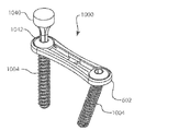
図24A〜図24Jを参照すると、アセンブリ1000は、安定化部材および動的要素を含み得る。アセンブリ1000では、安定化部材は、骨プレート602とすることができ、動的要素は、直線ペグ1004とすることができる。
Referring to FIGS. 24A-24J, the
2つの直線ペグ1004が、アセンブリ1000内で互いに面して示されている。この例では、直線ペグ1004は、先の動的要素、ステープル104、エルボペグ604、704、または直線ペグ804に取って代わる。各直線ペグ1004は、丸い頭部1032と、自由端1035で終わる骨接触脚部1034とを含む。頭部1032は、脚部1034と鈍角、直角、または鋭角を形成してもよい(図24D)。頭部1032は、直線ペグ804のマーク837と同様の、脚部1034の自由端1035に向かって指すマークを含むことができる。脚部1034は、図のように雄ねじを含むことができ、または脚部1034は、滑らかなものであってもよい。各直線ペグ1004は、独立して骨の穴内に挿入され、骨プレート602に固定されてもよい。直線ペグ1004は、脚部1034を骨内に螺合することによって、または前述のように止めねじ310で骨プレート602に固定されてもよい。シェルフ623は、頭部1032が骨プレート602の裏側614を通過しないように妨げる。直線ペグ1004は、上記のものと同様の原理に従って、ばね力を発生してもよい。図24Eは、頭部1032と脚部1034の間の角度を一時的に直線にするための、また脚部1034を骨の穴内に螺合するためのインサータ工具1040を示す。インサータ工具1040は、直線ペグ1004内のカニューレ状のもの1033内に延びる遠位シャフト1044を備えるトルク駆動特徴物1042(六角)を含む。
Two
2つの直線ペグ1004が示されているが、単一の直線ペグ1004がロッキングねじ106の反対側で使用されてもよい。この構成は示されていない。この場合、骨プレート602は、一端に(骨プレート102の穴116のように)雌ねじ山付き穴616、他端に受け部穴628を有することになる。このアセンブリは、雌ねじ山付き穴616内にロッキングねじ106、受け部穴628内に直線ペグ1004を含むことになる。
Although two
図25A〜図25Hを参照すると、アセンブリ1100は、安定化部材、動的要素、および1つまたは複数の締結具を含み得る。アセンブリ1100では、安定化部材は、骨プレート1102とすることができ、動的要素は、ワイヤペグ1104とすることができ、締結具は、止めねじ310を含み得る。
With reference to FIGS. 25A-25H,
骨プレート1102は、おもて側1112および裏側1114を有する。骨プレート1102は、いくつかの穴1116を含み、そのそれぞれが、雌ねじ山付き部分1118を含み得る。雌ねじ山付き部分1118は、おもて側1112に隣接してもよい。各穴1116は、内部シェルフ1123を含み得る。シェルフ1123は、裏側1114に隣接してもよい。ウェブ1124が2つの穴1116間に延びる。ウェブ1124は、裏側1114に隣接してもよい。ウェブ1124は、2つの穴1116を分離し、穴1116が互いに向かって細長くても存在してよい。2つの穴1116は、これらの特徴物がワイヤペグ1104を受け取るので、受け部穴1128と称される。各受け部穴1128は、非円形の貫通穴1129を含む。図の穴1129は、矩形であり、方形であってもよい。
2つのワイヤペグ1104が、アセンブリ1100内で互いに面して示されている。この例では、ワイヤペグ1104は、先の動的要素、ステープル114、エルボペグ604、704、直線ペグ804、1004に取って代わる。各ワイヤペグ1104は、矩形の断面を有する鋭く曲げられた、または折り畳まれたワイヤ片から形成される。各ワイヤペグ1104は、頭部1132と、ワイヤが鋭く曲げられた、または折り畳まれた自由端1135で終わる骨接触脚部1134とを含む。頭部1132は、この例では、ワイヤの外向きに曲げられた端部、または終端部分によって形成される。頭部1132は、脚部1134と鈍角、直角、または鋭角を形成してもよい。図25E〜図25Fでは、頭部1132の外向きに曲げられたワイヤ端部は、ワイヤペグ1104が自由な状態にあるとき脚部1134と直角を形成する。頭部1132の外向きに曲げられたワイヤ端部は、ワイヤペグ1104が自由な状態にあるとき、同一高さでない。各ワイヤペグ1104は、独立して骨の穴内に挿入され、骨プレート1102に固定されてもよい。ワイヤペグ1104は、止めねじ310によって骨プレート1102に固定されてもよい。シェルフ1123は、頭部1132が骨プレート1102の裏側1114を通過しないように妨げる。ワイヤペグ1104は、ばね力を発生してもよく、頭部1132の外向きに曲げられたワイヤ端部の高さが同一でないことにより、止めねじ310が締められるにつれて横へ弓形に反ることができる。応力を受けた、または弓形に反った状態のワイヤペグ1104が図25A〜図25D、図25G、および図25Hに示されている。
Two wire pegs 1104 are shown facing each other in
2つのワイヤペグ1104が示されているが、単一のワイヤペグ1104がロッキングねじ116の反対側で使用されてもよい。この構成は示されていない。この場合、骨プレートは、一端に(骨プレート102の穴116のように)雌ねじ山付き穴1116、他端に受け部穴1128を有することになる。このアセンブリは、雌ねじ山付き穴1116内にロッキングねじ116、受け部穴1128内に止めねじ310を備えるワイヤペグ1104を含むことになる。
Although two
図26A〜図26Hを参照すると、アセンブリ1200は、安定化部材、動的要素、および1つまたは複数の締結具を含み得る。アセンブリ1200では、安定化部材は、骨プレート1202とすることができ、動的要素は、ワイヤペグ1204とすることができ、締結具は、止めねじ310を含み得る。
Referring to FIGS. 26A-26H,
骨プレート1202は、おもて側1212および裏側1214を有する。骨プレート1202は、いくつかの穴1216を含み、そのそれぞれが、雌ねじ山付き部分1218を含み得る。雌ねじ山付き部分1218は、おもて側1212に隣接してもよい。各穴1216は、内部シェルフ1223を含み得る。シェルフ1223は、裏側1214に隣接してもよい。シェルフ1223は、内側アルコーブ1221を含み得る。ウェブ1224が2つの穴1216間に延びる。ウェブ1224は、裏側1214に隣接してもよい。ウェブ1224は、2つの穴1216を分離し、穴1216が互いに向かって細長くなくても存在してよい。2つの含まれる穴1216は、これらの特徴物がワイヤペグ1204を受け取るので、受け部穴1228と称される。各受け部穴1228は、非円形の貫通穴1229を含む。図の穴1229は、細長くなっており、楕円形、丸形、または矩形もしくは方形など別の形状であってもよい。
2つのワイヤペグ1204が、アセンブリ1200内で互いに面して示されている。この例では、ワイヤペグ1204は、先の動的要素、ステープル104、エルボペグ604、704、直線ペグ804、1004、またはワイヤペグ1104に取って代わる。各ワイヤペグ1204は、丸い断面を有する鋭く曲げられた、または折り畳まれたワイヤ片から形成される。各ワイヤペグ1204は、頭部1232と、ワイヤが鋭く曲げられた、または折り畳まれた自由端1235で終わる骨接触脚部1234とを含む。頭部1232は、この例では、ワイヤの外向きに曲げられた端部、または終端部分によって形成される。頭部1232は、脚部1234と鈍角、直角、または鋭角を形成してもよい。図26E〜図26Fでは、頭部1232の外向きに曲げられたワイヤ端部は、ワイヤペグが自由な状態にあるとき脚部1234と直角を形成する。頭部1232の外向きに曲げられたワイヤ端部は、ワイヤペグが自由な状態にあるとき、同一高さでない。各ワイヤペグ1204は、独立して骨の穴内に挿入され、骨プレート1202に固定されてもよい。ワイヤペグ1204は、止めねじ310で骨プレート1202に固定されてもよい。ワイヤペグ1204は、ばね力を発生してもよく、頭部1232の外向きに曲げられたワイヤ端部の高さが同一でないことにより、止めねじが締められるにつれて横へ弓形に反ることができる。応力を受けた、または弓形に反った状態のワイヤペグ1204が図26A〜図26D、図26G、および図26Hに示されている。
Two wire pegs 1204 are shown facing each other in
2つのワイヤペグ1204が示されているが、単一のワイヤペグ1204がロッキングねじ126の反対側で使用されてもよい。この構成は示されていない。この場合、骨プレートは、一端に(骨プレート102の穴116のように)雌ねじ山付き穴1216、他端に受け部穴1228を有することになる。このアセンブリは、雌ねじ山付き穴1216内にロッキングねじ126、受け部穴1228内に止めねじ310を備えるワイヤペグ1204を含むことになる。
Although two
図27Aおよび図27Bを参照すると、代替のワイヤペグ1302が、丸い断面を有する鋭く曲げられた、または折り畳まれたワイヤ片から形成される。各ワイヤペグ1304は、頭部1332と、ワイヤが鋭く曲げられた、または折り畳まれた自由端1335で終わる骨接触脚部1334とを含む。頭部1332は、この例では、ワイヤの外向きに曲げられた端部、または終端部分と、ワイヤの直線端部とによって形成される。頭部1332は、脚部1334と鈍角、直角、または鋭角を形成してもよい。図26E〜図26Fでは、頭部1332の外向きに曲げられたワイヤ端部は、ワイヤペグが自由な状態にあるとき脚部1334と直角を形成する。頭部1332の外向きに曲げられたワイヤ端部は、ワイヤペグが自由な状態にあるとき、頭部1332の直線端部と同一高さでない。このワイヤペグ1302は、ワイヤペグ1102およびワイヤペグ1202と相互交換可能に使用することができる。
Referring to FIGS. 27A and 27B, an
図28A〜図28Fを参照すると、アセンブリ1400は、安定化部材、動的要素、および1つまたは複数の締結具を含み得る。アセンブリ1400では、安定化部材は、骨プレート1402とすることができ、動的要素はステープル1404とすることができ、締結具はねじとすることができる。アセンブリ1400は、左にロッキングねじ1406、右に非ロッキングねじ1408を備えて示されている。
Referring to FIGS. 28A-28F,
骨プレート1402は、おもて側1412および裏側1414を有する。骨プレート1402は、おもて側1412および裏側1414を通って延びるいくつかの穴1416を含む。16の穴1416が示されているが、任意の数の穴があってよい。各穴1416は、各穴1416がロッキングねじ1406または非ロッキングねじ1408を受け入れるように雌ねじ山付き部分1418および非ねじ部分1420を含む。雌ねじ山付き部分1418は、ロッキングねじ1406の頭部1407上の雄ねじ1419と係合する。雌ねじ山付き部分1418は、裏側1414に隣接してもよい。非ねじ部分1420は、非ロッキングねじ1408の頭部1409と係合する。非ねじ部分1420は、おもて側1412に隣接してもよい。非ねじ部分1420は、凹形および/または細長いものであってよい。おもて側1412内の任意選択の溝1422が、プレート1402の正中に沿って延びる6つの穴1416のラインに沿って延びる。これらの6つの穴1416のそれぞれもまた、第2と第3の穴1416の間および第4と第5の穴1416の間に延びるウェブ1424を残して細長くなっている。第1と第2の穴1416、第3と第4の穴1416、または第5と第6の穴1416の間にウェブが示されていないが、これらのウェブが存在してもよい。ウェブ1424は、裏側1414に隣接してもよい。ウェブ1424は、第2と第3の穴1416および第4と第5の穴1416をそれぞれ分離し、穴14416が細長くなくても存在してよい。第1および第2の穴1416は、まとめて受け部1426と称され、含まれる穴1416は、受け部穴1428と称される。第2の受け部1426は、第3および第4の穴1416を含み、第3の受け部1426は、第5および第6の穴1416を含む。
ステープル1404は、本願の優先権チェーン内で識別される特許出願の少なくとも1つに記載されている。ステープル1404は、特許文献1の図11および図12のインプラント200、図15A〜図16Bのインプラント300、図21および図22のインプラント600、図23A〜図24のインプラント800、もしくは図78および図79のインプラント2200、または特許文献2の図1〜図3のインプラント100、図4および図5のステープル300、図7のステープル400、図8のステープル480、もしくは図10Aおよび図10Bのインプラント2100とすることができる。図のステープル1404は、特許文献1の図78および図79のインプラント2200である。
ステープル1404は、本体1440またはブリッジ、第1の脚部1442、および第2の脚部1444を含む。ブリッジは、第1の端部1446と第2の端部1448の間に延びる。第1の脚部1442は、第1の端部1446に結合され、第1の自由端1443において終わる。第2の脚部1444は、第2の端部1448から延び、第2の自由端1445において終わる。第1の突起1450が第1の端部1446から延び、第2の突起1452が第2の端部1448から延びる。
ステープル1404は、その形状が外力、たとえばステープルインサータ工具によって加えられる外力の影響下にある挿入状態、または弾性変形された状態を有する。弾性変形された状態では、第1の距離が自由端1443、1445を分離する。また、ステープル1404は、重力以外、外力がステープルに作用していないときのその形状である自由な状態、または弛緩状態を有する。弛緩状態では、第2の距離が自由端1443、1445を分離する。第2の距離は、第1の距離と異なる。図の例では、弾性変形された状態では、ステープル1404の脚部1442、1444が互いに平行である。しかし、脚部1442、1444は、弾性変形された状態では、収束しても発散してもよい。図の例では、弛緩状態において、ステープルの脚部1442、1444がそれらの自由端1443、1445または先端にて収束し、その結果、第2の距離は、第1の距離より小さい。しかし、脚部1442、1444は、それらの自由端1443、1445にて発散してもよく、または脚部1442、1444は、弛緩状態において平行であってもよい。ステープル1404は、外力の影響下で弾性変形された状態を呈する。ステープル1404は、外力が除去されて直ちに自由な状態に戻ってもよい。ステープル1404の脚部1442、1444が骨の穴内に係合されている場合には、ステープルは、骨の抵抗により自由な状態に向かって一部弛緩することができるだけであってもよい。この状況では、ステープル1404は、弾性変形された状態と弛緩状態との間で荷重された状態にあってもよい。この例では、ステープル1404は、骨プレート1402にロックされていないが、他の例では、ステープルは、骨プレートにロックされる。この例では、ステープル1404の本体1440は、受け部1426内で止まり、ステープル脚部1442、1444は、受け部穴1428を通って延び、骨プレート1402の裏側1414から突出する。受け部1426は、骨プレート1402に対して所定の向きおよび相対位置でステープル1404を保持する。受け部1426は、骨プレートに対して所定の向きおよび相対位置でステープルを保持するように共に機能する特徴物のグループの一例である。異なる特徴物または特徴物のグループが同じ機能を提供してもよい。たとえば、ステープル1404の本体1440は、骨プレート1402のおもて側1412の上、もしくはウェブ上で止まってもよく、またはウェブ1424は、本体1440が裏側1414を通過しないように妨げるための止め具もしくはドッキング点として働くようにレッジもしくは他のサポートによって置き換えられてもよい。さらに、ウェブ1424は、骨プレート1402上ではなくステープル1404上の1つまたは複数の停止特徴物またはドッキング特徴物によって置き換えられてもよい。たとえば、突起1450、1452は、停止特徴物またはドッキング特徴物として働くことができる。
The
ロッキングねじ1406は、骨プレート1402内の任意の穴1416にしっかりロックする。ロッキングねじ1406は、穴1416の雌ねじ山付き部分1418内にきつく螺合されたとき骨プレート1402内の穴1416にロックする雄ねじ山付き頭部1407を含み得る。ロッキングねじ1406は、本願の優先権チェーン内で識別される特許出願の少なくとも1つに開示されている設計であってもよい。ロッキングねじ1406は、特許文献3の図11の骨固定デバイス360、図24〜図26の骨固定デバイス500、図27〜図30の骨固定デバイス600とすることができる。
Locking
非ロッキングねじ1408は、骨プレート1402内の穴1416にロックしない。その代わりに、それは、植え込み後、ねじ穴1416の範囲内で自由に回転および平行移動できるままである。非ロッキングねじ1408は、ねじ穴1416に対して多軸方向で位置決め可能とすることができる。非ロッキングねじ1408は、穴1416の非ねじ部分1420と共にボールソケット継手を形成する外部表面を備える頭部1409を含み得る。外部表面は、凸形、球形、または円錐形であってよい。
ねじ1406とねじ1408は、骨プレート1402内のねじ穴1416内で相互交換可能である。
図9Aおよび図9Bを参照すると、通常のヒトの足10は、距骨12、踵骨14、舟状骨16、内側楔状骨18、中間楔状骨20、外側楔状骨22、立方骨24、第1中足骨26、第2中足骨28、第3中足骨30、第4中足骨32、第5中足骨34、第1基節骨36、第2基節骨38、第3基節骨40、第4基節骨42、第5基節骨44、第1中節骨46、第2中節骨48、第3中節骨50、第4中節骨52、第1末節骨54、第2末節骨56、第3末節骨58、第4末節骨60、および第5末節骨62を含む、26個の骨を含む。
Referring to FIGS. 9A and 9B, a normal
図14を参照すると、いくつかの異なる外科器械がキットまたはセットで提供され得る。 Referring to FIG. 14, several different surgical instruments can be provided in a kit or set.
図15を参照すると、プレートサイズ設定テンプレートは、異なるプレート形状のためにいくつかの個々のテンプレートを含んでもよく、そのそれぞれをサイズ設定テンプレートから除去することができる。テンプレーティングは、開示されている装置を使用するための方法におけるステップとすることができる。 Referring to FIG. 15, the plate sizing template may include several individual templates for different plate shapes, each of which can be removed from the sizing template. Templating can be a step in a method for using the disclosed apparatus.
図16および図17を参照すると、プレート曲げ器は、ねじ山付き端部と、ねじ山付き端部の反対側のフォーク形端部とを含み得る。プレート曲げ器は、非ロッキング多軸ドリルガイド(図20)のためのハンドルとしても使用されてよい。プレート曲げまたはプレートコンタリングは、開示されている装置を使用するための方法における1ステップとすることができる。 With reference to FIGS. 16 and 17, the plate bender may include a threaded end and a fork-shaped end opposite the threaded end. The plate bending machine may also be used as a handle for a non-locking multi-axis drill guide (FIG. 20). Plate bending or plate contouring can be a step in the method for using the disclosed apparatus.
図18を参照すると、ねじ山付きドリルガイドは、骨プレート、たとえば骨プレート902内のねじ山付き穴内にロックし、ドリルを正確に案内し、ロッキングねじ106を受け取るために骨内に穴を作ることができる。ねじ山付きドリルガイドは、骨プレートインサータ器械として使用されてもよい。骨プレートを挿入することは、開示されている装置を使用するための方法におけるステップとすることができる。
Referring to FIG. 18, a threaded drill guide locks into a threaded hole in a bone plate, eg,
図19を参照すると、骨プレート、たとえば骨プレート902内の穴内で一時的に固定するために、オリーブワイヤが使用され得る。ロッキング骨ねじのための穿孔および/またはロッキング骨ねじのためのタッピングは、開示されている装置を使用するための方法におけるステップとすることができる。
Referring to FIG. 19, an olive wire can be used to temporarily secure within a bone plate, eg, a hole in
図20を参照すると、非ロッキング多軸ドリルガイドは、骨プレート、たとえば骨プレート902内の穴と係合し、ドリルを正確に案内し、ロッキングねじ108を受け取るために骨内に穴を作ることができる。非ロッキング骨ねじのための穿孔および/または非ロッキング骨ねじのためのタッピングは、開示されている装置を使用するための方法におけるステップとすることができる。
Referring to FIG. 20, a non-locking multi-axis drill guide engages a hole in a bone plate, eg,
図21を参照すると、ロッキングねじまたは非ロッキングねじは、骨プレートのねじ穴内で相互交換可能に使用されてよい。ねじドライバ器械は、手動または動力源からのトルクをねじに伝達し、骨内に、またロッキングねじの場合、骨プレートのねじ穴のねじ山内にねじを駆動する。ねじを駆動し、骨、またロッキングねじの場合、骨プレートのねじ穴のねじ山とねじ係合させることは、開示されている装置を使用するための方法におけるステップとすることができる。 Referring to FIG. 21, locking or non-locking screws may be used interchangeably within the screw holes in the bone plate. The screw driver instrument transmits torque from a manual or power source to the screw and drives the screw into the bone and, in the case of a locking screw, into the thread of the screw hole in the bone plate. Driving the screw, and in the case of a bone, and in the case of a locking screw, threaded engagement with the threaded hole of the bone plate can be a step in the method for using the disclosed device.
図22を参照すると、ステープルドリルガイドは、骨プレート、たとえば骨プレート902内の1対の穴と係合し、ドリルを正確に案内し、ステープル104を受け取るために骨内に穴を作ることができる。ステープルのための穿孔は、開示されている装置を使用するための方法におけるステップとすることができる。
Referring to FIG. 22, a staple drill guide may engage a pair of holes in a bone plate, eg,
ステープルインサータは、挿入のためにステープル104を保持することができる。ステープルインサータは、本願の優先権チェーン内で識別される特許出願の少なくとも1つに記載されている。たとえば、ステープル104は、挿入のためにその脚部が強制的に平行状態にされて保持され得る。ステープルインサータは、ステープルインサータがステープル104に取り付けられている間にステープル104が受け部内で完全に着座され得るように、骨プレートおよび骨部分に面する側とは反対側のステープルの側から精密にステープル104と係合することができる。ステープルが骨プレートを通して挿入された後で、ステープルインサータを除去することにより、ステープル脚部は弛緩し、ステープル脚部が互いに対して鋭角である自由な状態に戻ろうと試みることができる(図1A〜図1F)。ステープルを挿入することは、開示されている装置を使用するための方法におけるステップとすることができる。
The staple inserter can hold the
図22の最も右の図は、ヒトの左足の第1リスフラン関節(または第1足根中足関節)をまたいで延びる骨プレート902およびステープル104を示す。ステープルは、各ステープル脚部が関節の異なる側にあるように、骨プレート902内の穴を通って延びる。ステープルインサータが除去された後、ステープルが弛緩するにつれて、ステープル脚部は、関節をまたいで機械的荷重または応力を加える。ステープル104が図1A〜図1Fに示されているその自由な状態に向かって弛緩するにつれて、ステープル脚部は、関節をまたいで圧縮荷重または応力を加える。逆に、発散する脚部を備えるステープルは、関節をまたいで引張荷重または応力を加えることになる。
The rightmost view of FIG. 22 shows a
図23を参照すると、骨プレート902、ステープル104、ロッキングねじ106、および非ロッキングねじ108が、第1リスフラン関節をまたいで最終的に植え込まれた状態で示されている。ロッキングねじ106をステープル104の一方の脚部に隣接して、また非ロッキングねじ108をステープル104の他方の脚部に隣接して使用することが特に有利となり得る。これは図23に示されており、ロッキングねじ106は、内側楔状骨18内で使用され、非ロッキングねじ108は、第1中足骨26内で使用されている。しかし、非ロッキングねじ108が内側楔状骨18内で使用され、ロッキングねじ106が第1中足骨26内で使用される反対の構成も企図されている。
Referring to FIG. 23,
開示されている装置を使用する方法は、上述のステップの任意の組合せを任意の順序で含み得る。 A method using the disclosed apparatus may include any combination of the above steps in any order.
開示されている装置を使用する方法の一例は、骨プレートを第1の骨部分および第2の骨部分に隣接して挿入するステップであって、不連続が第2の骨部分を第1の骨部分から分離しており、骨プレートは、不連続をまたいで延び、骨プレートは、少なくとも4つの穴を含む、ステップと、骨プレートを通してねじ山付きドリルガイドを第1の穴にロックするステップであって、骨プレートの第1の穴が第1の骨部分に隣接する、ステップと、ねじ山付きドリルガイドを通して第1の骨部分内に第1の骨の穴を穿孔するステップと、骨プレートの第1の穴を通してロッキングねじを駆動し、第1の骨の穴および骨プレートの第1の穴とねじ係合させるステップと、ステープルドリルガイドを、骨プレートを通して第2の穴と、また骨プレートを通して第3の穴と係合させるステップであって、骨プレートの第2の穴は、第1の骨部分に隣接し、骨プレートの第3の穴は、第2の骨部分に隣接する、ステップと、ステープルドリルガイドを通して第1の骨部分内に第2の骨の穴を穿孔するステップと、ステープルドリルガイドを通して第2の骨部分内に第3の骨の穴を穿孔するステップと、骨プレートの第2の穴を通してステープルの第1の脚部を挿入し、第2の骨の穴とねじ係合させ、骨プレートの第3の穴を通してステープルの第2の脚部を挿入し、第3の骨の穴とねじ係合させるステップであって、ステープルの第1の脚部は、ステープルが挿入されている間、ステープルの第2の脚部と平行であり、ステープルの第1の脚部と第2の脚部は、ステープルが挿入された後、互いに向かって圧縮する、ステップと、非ロッキング多軸ドリルガイドを、骨プレートを通して第4の穴と係合させるステップであって、骨プレートの第4の穴は、第2の骨部分に隣接する、ステップと、非ロッキング多軸ドリルガイドを通して第2の骨部分内に第4の骨の穴を穿孔するステップと、骨プレートの第4の穴を通して非ロッキングねじを駆動し、第4の骨の穴とねじ係合させ、骨プレートの第4の穴と非ロッキング係合させるステップとを含む。 One example of a method of using the disclosed device is to insert a bone plate adjacent to a first bone portion and a second bone portion, wherein the discontinuity causes the second bone portion to be the first bone portion. Separate from the bone portion, the bone plate extending across the discontinuity, the bone plate including at least four holes, and locking the threaded drill guide through the bone plate to the first hole A first hole in the bone plate is adjacent to the first bone portion; drilling a hole in the first bone into the first bone portion through a threaded drill guide; Driving the locking screw through the first hole in the plate to threadably engage the first bone hole and the first hole in the bone plate; and the staple drill guide through the bone plate and the second hole; Bone plate Engaging the third hole through, wherein the second hole of the bone plate is adjacent to the first bone portion, and the third hole of the bone plate is adjacent to the second bone portion. Piercing a second bone hole in the first bone portion through the staple drill guide and drilling a third bone hole in the second bone portion through the staple drill guide; Inserting the first leg of the staple through the second hole of the bone plate, threadingly engaging the hole of the second bone, inserting the second leg of the staple through the third hole of the bone plate; Threading engagement with a third bone hole, wherein the first leg of the staple is parallel to the second leg of the staple while the staple is being inserted; The leg and the second leg are connected to each other after the staples are inserted. Compressing and engaging a non-locking polyaxial drill guide through the bone plate with the fourth hole, wherein the fourth hole of the bone plate is adjacent to the second bone portion; Piercing a fourth bone hole in the second bone portion through a non-locking polyaxial drill guide, driving a non-locking screw through the fourth hole in the bone plate, and And non-locking engagement with the fourth hole of the bone plate.
また、先の方法は、ステープルを骨プレートに固定するステップをも含み得る。ステープルは、止めねじ、延性タブ、またはスナップ嵌めで骨プレート702に固定されてもよい。ステープルは、ステープルの一部分が骨プレートの一部分内にモールドされることによって骨プレートに固定されてもよい。ステープルは、骨プレートと一体に形成されることによって骨プレートに固定されてもよい。
The previous method may also include securing the staple to the bone plate. Staples may be secured to
開示されている装置を使用する方法の別の例は、骨プレートを第1の骨部分および第2の骨部分に隣接して挿入するステップであって、不連続が第2の骨部分を第1の骨部分から分離しており、骨プレートは、不連続をまたいで延びる、ステップと、骨プレートを通る第1の穴を通して第1の骨部分内に第1の骨の穴を穿孔するステップと、骨プレートを通る第2の穴を通して第2の骨部分内に第2の骨の穴を穿孔するステップと、骨プレートの第1の穴を通して第1のエルボペグの脚部を挿入し、第1の骨の穴と係合させ、第1のエルボペグの頭部を骨プレートの第1の穴に隣接して配置するステップと、骨プレートの第2の穴を通して第2のエルボペグの脚部を挿入し、第2の骨の穴と係合させ、第2のエルボペグの頭部を骨プレートの第2の穴に隣接して配置するステップと、第1のエルボペグの頭部を通る開口および骨プレートの第1の穴を通して第1の骨ねじを駆動し、第1のエルボペグの脚部の近くで第1の骨部分とねじ係合させるステップと、第2のエルボペグの頭部を通る開口および骨プレートの第2の穴を通して第2の骨ねじを駆動し、第2のエルボペグの脚部の近くで第2の骨部分とねじ係合させるステップとを含む。 Another example of a method of using the disclosed device is the step of inserting a bone plate adjacent to the first bone portion and the second bone portion, wherein the discontinuity causes the second bone portion to be Separating from a bone portion, the bone plate extending across the discontinuity, and drilling a hole in the first bone through the first hole through the bone plate and into the first bone portion. Drilling a second bone hole into the second bone portion through a second hole through the bone plate, inserting a first elbow peg leg through the first hole in the bone plate, and Engaging the bone hole with the first elbow peg and positioning the head of the first elbow peg adjacent to the first hole in the bone plate; and passing the leg of the second elbow peg through the second hole in the bone plate. Insert and engage with the second bone hole and place the head of the second elbow peg on the bone plate The first bone screw is driven through an opening through the head of the first elbow peg and through the first hole in the bone plate and adjacent to the leg of the first elbow peg. Screw engaging the first bone portion, driving the second bone screw through an opening through the head of the second elbow peg and a second hole in the bone plate, near the leg of the second elbow peg And screw engaging the second bone portion.
開示されている装置を使用する方法のさらに別の例は、骨プレートを第1の骨部分および第2の骨部分に隣接して挿入するステップであって、不連続が第2の骨部分を第1の骨部分から分離しており、骨プレートは、不連続をまたいで延びる、ステップと、骨プレートを通る第1の穴を通して第1の骨部分内に第1の骨の穴を穿孔するステップと、骨プレートを通る第2の穴を通して第2の骨部分内に第2の骨の穴を穿孔するステップと、骨プレートの第1の穴を通して第1のエルボペグの脚部を挿入し、第1の骨の穴と係合させ、第1のエルボペグの頭部を骨プレートの第1の穴の上に配置するステップと、骨プレートの第2の穴を通して第2のエルボペグの脚部を挿入し、第2の骨の穴と係合させ、第2のエルボペグの頭部を骨プレートの第2の穴の上に配置するステップと、第1のエルボペグの頭部に接して第1の止めねじを締めるステップと、第2のエルボペグの頭部に接して第2の止めねじを締めるステップとを含む。 Yet another example of a method of using the disclosed apparatus is the step of inserting a bone plate adjacent to the first bone portion and the second bone portion, wherein the discontinuity includes the second bone portion. Separated from the first bone portion, the bone plate extends across the discontinuity, and drills a hole in the first bone into the first bone portion through the first hole through the bone plate. Drilling a second bone hole into the second bone portion through a second hole through the bone plate and inserting a first elbow peg leg through the first hole in the bone plate; Engaging the first bone hole to position the head of the first elbow peg over the first hole in the bone plate; and passing the leg of the second elbow peg through the second hole in the bone plate. Insert and engage with the second bone hole and the second elbow peg head to the bone plate Placing over the second hole; tightening the first set screw in contact with the head of the first elbow peg; and tightening the second set screw in contact with the head of the second elbow peg. Including.
開示されている装置を使用する方法のさらに別の例は、骨プレートを第1の骨部分および第2の骨部分に隣接して挿入するステップであって、不連続が第2の骨部分を第1の骨部分から分離しており、骨プレートは、不連続をまたいで延びる、ステップと、骨プレートを通る第1の穴を通して第1の骨部分内に第1の骨の穴を穿孔するステップと、骨プレートを通る第2の穴を通して第2の骨部分内に第2の骨の穴を穿孔するステップと、骨プレートの第1の穴を通して第1の直線ペグの脚部を挿入し、第1の骨の穴と係合させ、第1の直線ペグの頭部を骨プレートの第1の穴内に配置するステップと、骨プレートの第2の穴を通して第2の直線ペグの脚部を挿入し、第2の骨の穴と係合させ、第2の直線ペグの頭部を骨プレートの第2の穴内に配置するステップと、第1の直線ペグの頭部に接して第1の止めねじを締めるステップと、第2の直線ペグの頭部に接して第2の止めねじを締めるステップとを含む。 Yet another example of a method of using the disclosed apparatus is the step of inserting a bone plate adjacent to the first bone portion and the second bone portion, wherein the discontinuity includes the second bone portion. Separated from the first bone portion, the bone plate extends across the discontinuity, and drills a hole in the first bone into the first bone portion through the first hole through the bone plate. Piercing a second bone hole in the second bone portion through a second hole through the bone plate and inserting a leg of the first straight peg through the first hole in the bone plate. Engaging the first bone hole and positioning the head of the first straight peg within the first hole of the bone plate; and the legs of the second straight peg through the second hole of the bone plate Is inserted into the second bone hole and the head of the second straight peg is inserted into the second hole in the bone plate. INCLUDED placing the steps of tightening the first set screw in contact with the head of the first straight line peg, and a step of tightening the second locking screw in contact with the head of the second straight line pegs.
先の方法は、止めねじを締める前に、第1および/または第2の直線ペグを回転し、脚部を骨プレートに対して所望の向きに位置決めするステップをも含み得る。 The previous method may also include rotating the first and / or second linear pegs to position the legs in a desired orientation relative to the bone plate prior to tightening the set screw.
本明細書に開示されている方法は、記載の方法を実施するための1つまたは複数のステップまたはアクションを含む。方法ステップおよび/またはアクションは、互いに相互交換されてもよい。換言すれば、特定の順序のステップまたはアクションが実施形態の適正な動作のために必要とされない限り、特定のステップおよび/またはアクションの順序および/または使用は、修正されてもよい。 The methods disclosed herein include one or more steps or actions for performing the described method. Method steps and / or actions may be interchanged with one another. In other words, the order and / or use of specific steps and / or actions may be modified unless a specific order of steps or actions is required for proper operation of the embodiments.
本明細書を通して、「一実施形態」または「実施形態」に言及することは、その実施形態に関連して述べられている特定の特徴、構造、または特性が少なくとも1つの実施形態に含まれることを意味する。したがって、本明細書を通して述べられている、引用句またはその変形形態は、必ずしもすべて同じ実施形態を指していない。 Throughout this specification, references to “one embodiment” or “an embodiment” include that a particular feature, structure, or characteristic described in connection with that embodiment is included in at least one embodiment. Means. Thus, the quotes or variations thereof mentioned throughout this specification are not necessarily all referring to the same embodiment.
同様に、実施形態の上記の説明では、開示を簡素化するために、様々な特徴が単一の実施形態、図、またはその説明において共にグループ化されることがあることを理解されたい。しかし、開示のこの方法は、任意の請求項がその請求項に明示的に述べられているものより多くの特徴を必要とするという意図を反映するものと解釈されるべきでない。むしろ、以下の特許請求の範囲が反映するように、発明性のある態様は、どの単一の先に開示されている実施形態のすべての特徴より少ないものの組合せにある。したがって、この詳細な説明に続く特許請求の範囲は、これによりこの詳細な説明に明示的に組み込まれ、各請求項は、それ自体、別個の実施形態となる。本開示は、独立請求項の並べ替えすべてを、それらの従属請求項と共に含む。 Similarly, in the above description of embodiments, it should be understood that various features may be grouped together in a single embodiment, figure, or description thereof, in order to simplify the disclosure. This method of disclosure, however, should not be interpreted as reflecting an intention that any claim requires more features than are expressly recited in that claim. Rather, as the following claims reflect, inventive aspects lie in combinations of fewer than all the features of any single previously disclosed embodiment. Thus, the claims following this detailed description are hereby expressly incorporated into this detailed description, with each claim standing on its own as a separate embodiment. This disclosure includes all permutations of the independent claims along with their dependent claims.
特許請求の範囲において特徴または要素に対して「第1」という用語を述べることは、必ずしも第2または追加のそのような特徴または要素の存在を暗示しない。ミーンズプラスファンクション形式で述べられている要素は、米国特許法第112条6項に従って解釈されることが意図されている。本技術の基礎となる原理から逸脱することなしに上記の実施形態の詳細に変更を加えることができることが、当業者には明らかになろう。 In the claims, the term “first” to a feature or element does not necessarily imply the presence of a second or additional such feature or element. Elements described in means-plus-function form are intended to be construed in accordance with 35 USC 112.26. It will be apparent to those skilled in the art that changes can be made to the details of the above embodiments without departing from the underlying principles of the technology.
本技術の特定の実施形態および応用例について例示し述べたが、本技術は、本明細書に開示されているその構成および構成要素に限定されないことを理解されたい。当業者には明らかな様々な修正、変更、および変形を、本技術の精神および範囲から逸脱することなしに、本明細書に開示されている本技術の方法およびシステムの構成、動作、および詳細に加えることができる。 While specific embodiments and applications of the technology have been illustrated and described, it is to be understood that the technology is not limited to the configurations and components disclosed herein. Various modifications, changes and variations apparent to those skilled in the art may be made without departing from the spirit and scope of the technology without departing from the spirit, scope, and details of the methods and systems of the technology and systems disclosed herein. Can be added to.
Claims (24)
第1の脚部及び第2の脚部を備え、骨内への挿入のために弾性変形された状態と骨内に係合される弛緩状態との間で変形可能である動的要素と、
を備え、
前記安定化部材は、前記第1の脚部及び前記第2の脚部が前記裏側から突出するように前記動的要素の少なくとも一部を受け取るように構成され、
前記弾性変形された状態では、前記第1の脚部の自由端は、前記第2の脚部の自由端から第1の距離であり、前記弛緩状態では、前記第1の脚部の前記自由端は、前記第2の脚部の前記自由端から第2の距離であり、前記第2の距離は、前記第1の距離より小さい、骨固定システム。 A stabilizing member comprising a front side and a back side opposite the front side;
Comprising a first leg and a second leg, and a dynamic element is deformable between a relaxed state that is engaged elastically deformed state and the bone for insertion into the bone,
With
The stabilizing member is configured to receive at least a portion of the dynamic element such that the first leg and the second leg protrude from the backside;
In the elastically deformed state, the free end of the first leg is a first distance from the free end of the second leg, and in the relaxed state, the free end of the first leg. The bone fixation system, wherein an end is a second distance from the free end of the second leg, and the second distance is less than the first distance.
前記安定化部材は、前記本体を受け取るように構成される請求項1から請求項3のいずれか一項に記載のシステム。 The dynamic element further comprises a body,
4. A system according to any one of the preceding claims, wherein the stabilizing member is configured to receive the body.
前記本体は、前記安定化部材に当接する請求項4から8のいずれか一項に記載のシステム。 The dynamic element further comprises a body,
The system according to claim 4, wherein the main body abuts on the stabilizing member.
前記動的要素は、本体をさらに備え、前記本体は、前記溝内に位置する請求項8又は請求項9に記載のシステム。 The stabilizing member includes a first receiving portion hole, a second receiving portion hole, and a groove extending between the first receiving portion hole and the second receiving portion hole,
10. A system according to claim 8 or claim 9, wherein the dynamic element further comprises a body, the body located in the groove.
前記安定化部材は、サポートを備え、前記本体は、前記サポート上に載置され、前記サポートは、前記本体が前記安定化部材を通過することを妨げる請求項4から11のいずれか一項に記載のシステム。 The dynamic element further comprises a body,
12. The stabilization member according to any one of claims 4 to 11, wherein the stabilization member comprises a support, the body is mounted on the support, and the support prevents the body from passing through the stabilization member. The described system.
前記サポートは、前記第1の受け部穴および前記第2の受け部穴を分離するウェブを備える請求項12に記載のシステム。 The stabilizing member includes a first receiving portion hole and a second receiving portion hole,
The system of claim 12, wherein the support comprises a web that separates the first receptacle hole and the second receptacle hole.
b)前記動的要素は、弾性変形可能な材料内に少なくとも一部封入される、
の一つが適用される請求項14に記載のシステム。 a) the stabilizing member comprises a web, the dynamic element further comprises a body, the web surrounding at least a portion of the body;
b) the dynamic element is at least partially encapsulated in an elastically deformable material;
15. A system according to claim 14, to which one of the following applies.
b)前記ロッキング機構は、前記安定化部材内に形成された延性タブを備え、前記延性タブは、開状態と閉状態とを備え、前記動的要素は、前記延性タブが前記閉状態にあるとき前記安定化部材にロックされる、
c)前記ロッキング機構は、前記安定化部材のウェブを備え、前記ウェブは、前記本体の少なくとも一部分を取り囲む、
の一つが適用される請求項16に記載のシステム。 a) the locking mechanism comprises a threaded socket formed in the stabilizing member and a set screw complementary to the threaded socket;
b) the locking mechanism comprises a ductile tab formed in the stabilizing member, the ductile tab comprising an open state and a closed state, and the dynamic element wherein the ductile tab is in the closed state When locked to the stabilizing member,
c) the locking mechanism comprises a web of the stabilizing member, the web surrounding at least a portion of the body;
17. A system according to claim 16, wherein one of the following is applied.
を備え、
前記安定化部材は、前記締結具が前記安定化部材の前記裏側から突出するように前記締結具を受け取るように構成される請求項1から17のいずれか一項に記載のシステム。 With fasteners,
18. A system according to any preceding claim, wherein the stabilization member is configured to receive the fastener such that the fastener projects from the back side of the stabilization member.
Applications Claiming Priority (5)
| Application Number | Priority Date | Filing Date | Title |
|---|---|---|---|
| US201562192059P | 2015-07-13 | 2015-07-13 | |
| US62/192,059 | 2015-07-13 | ||
| US15/209,623 | 2016-07-13 | ||
| PCT/US2016/042154 WO2017011589A1 (en) | 2015-07-13 | 2016-07-13 | Bone plates with dynamic elements |
| US15/209,623 US10299842B2 (en) | 2013-12-20 | 2016-07-13 | Bone plates with dynamic elements |
Related Child Applications (1)
| Application Number | Title | Priority Date | Filing Date |
|---|---|---|---|
| JP2019121731A Division JP6637212B2 (en) | 2015-07-13 | 2019-06-28 | Bone plate with dynamic elements |
Publications (2)
| Publication Number | Publication Date |
|---|---|
| JP2018520780A JP2018520780A (en) | 2018-08-02 |
| JP6560434B2 true JP6560434B2 (en) | 2019-08-14 |
Family
ID=57757529
Family Applications (4)
| Application Number | Title | Priority Date | Filing Date |
|---|---|---|---|
| JP2018500765A Active JP6560434B2 (en) | 2015-07-13 | 2016-07-13 | Bone plate with dynamic elements |
| JP2019121731A Active JP6637212B2 (en) | 2015-07-13 | 2019-06-28 | Bone plate with dynamic elements |
| JP2019229584A Pending JP2020039966A (en) | 2015-07-13 | 2019-12-19 | Bone plates with dynamic elements |
| JP2020120652A Active JP7071447B2 (en) | 2015-07-13 | 2020-07-14 | Bone plate with dynamic elements |
Family Applications After (3)
| Application Number | Title | Priority Date | Filing Date |
|---|---|---|---|
| JP2019121731A Active JP6637212B2 (en) | 2015-07-13 | 2019-06-28 | Bone plate with dynamic elements |
| JP2019229584A Pending JP2020039966A (en) | 2015-07-13 | 2019-12-19 | Bone plates with dynamic elements |
| JP2020120652A Active JP7071447B2 (en) | 2015-07-13 | 2020-07-14 | Bone plate with dynamic elements |
Country Status (8)
| Country | Link |
|---|---|
| US (3) | US10299842B2 (en) |
| EP (2) | EP3563785B1 (en) |
| JP (4) | JP6560434B2 (en) |
| CN (3) | CN110151291B (en) |
| AU (6) | AU2016294449B2 (en) |
| CA (1) | CA2989892C (en) |
| HK (2) | HK1252850A1 (en) |
| WO (1) | WO2017011589A1 (en) |
Cited By (1)
| Publication number | Priority date | Publication date | Assignee | Title |
|---|---|---|---|---|
| JP7071447B2 (en) | 2015-07-13 | 2022-05-19 | クロスローズ エクストリミティ システムズ リミテッド ライアビリティ カンパニー | Bone plate with dynamic elements |
Families Citing this family (47)
| Publication number | Priority date | Publication date | Assignee | Title |
|---|---|---|---|---|
| US7240677B2 (en) * | 2003-02-03 | 2007-07-10 | Biomedical Enterprises, Inc. | System and method for force, displacement, and rate control of shaped memory material implants |
| US10251757B2 (en) * | 2008-09-17 | 2019-04-09 | Skeletal Dynamics Llc | Grooved slot allowing adjustment of the position of a bone fixation device for osteosynthesis |
| US11253252B2 (en) | 2012-07-30 | 2022-02-22 | Conextions, Inc. | Devices, systems, and methods for repairing soft tissue and attaching soft tissue to bone |
| US11944531B2 (en) | 2012-07-30 | 2024-04-02 | Conextions, Inc. | Devices, systems, and methods for repairing soft tissue and attaching soft tissue to bone |
| US10219804B2 (en) | 2012-07-30 | 2019-03-05 | Conextions, Inc. | Devices, systems, and methods for repairing soft tissue and attaching soft tissue to bone |
| US10390935B2 (en) * | 2012-07-30 | 2019-08-27 | Conextions, Inc. | Soft tissue to bone repair devices, systems, and methods |
| US11957334B2 (en) | 2012-07-30 | 2024-04-16 | Conextions, Inc. | Devices, systems, and methods for repairing soft tissue and attaching soft tissue to bone |
| US10307191B2 (en) * | 2015-08-19 | 2019-06-04 | In2Bones Usa, Llc | Subtalar plate implant |
| AU2014365821B2 (en) | 2013-12-20 | 2019-10-03 | Crossroads Extremity Systems, Llc | Polyaxial locking hole |
| US11583384B2 (en) | 2014-03-12 | 2023-02-21 | Conextions, Inc. | Devices, systems, and methods for repairing soft tissue and attaching soft tissue to bone |
| US11202626B2 (en) | 2014-07-10 | 2021-12-21 | Crossroads Extremity Systems, Llc | Bone implant with means for multi directional force and means of insertion |
| US10492841B2 (en) | 2014-07-10 | 2019-12-03 | Crossroads Extremity Systems, Llc | Bone implant and means of insertion |
| US10376268B2 (en) | 2015-02-19 | 2019-08-13 | First Ray, LLC | Indexed tri-planar osteotomy guide and method |
| US20170181779A1 (en) * | 2015-12-29 | 2017-06-29 | Orthohelix Surgical Designs, Inc. | Active compression plate and method for its use |
| WO2017147213A1 (en) * | 2016-02-23 | 2017-08-31 | Life Spine, Inc. | Spinal interbody cage implant with flexible barbs |
| US11696822B2 (en) | 2016-09-28 | 2023-07-11 | Conextions, Inc. | Devices, systems, and methods for repairing soft tissue and attaching soft tissue to bone |
| US11864753B2 (en) | 2017-02-06 | 2024-01-09 | Crossroads Extremity Systems, Llc | Implant inserter |
| WO2018148284A1 (en) * | 2017-02-07 | 2018-08-16 | Crossroads Extremity Systems, Llc | Counter-torque implant |
| USD870284S1 (en) | 2017-07-31 | 2019-12-17 | Crossroads Extremity Systems, Llc | Osteosynthesis clip |
| USD869657S1 (en) | 2017-07-31 | 2019-12-10 | Crossroads Extremity Systems, Llc | Bone plate |
| US11547397B2 (en) | 2017-12-20 | 2023-01-10 | Conextions, Inc. | Devices, systems, and methods for repairing soft tissue and attaching soft tissue to bone |
| US12102317B2 (en) | 2017-12-20 | 2024-10-01 | Conextions, Inc. | Devices, systems, and methods for repairing soft tissue and attaching soft tissue to bone |
| US20190357951A1 (en) * | 2018-05-22 | 2019-11-28 | Subluxation Safe Asset, LP | Staple and plate hard tissue fixation |
| US11246588B2 (en) * | 2018-06-28 | 2022-02-15 | Ortho Solutions Holdings Limited | Superelastic bone compression staple in staple system |
| US11051804B2 (en) * | 2018-07-02 | 2021-07-06 | DePuy Synthes Products, Inc. | Orthopedic fixation system and method of use thereof |
| US11141285B2 (en) * | 2018-08-06 | 2021-10-12 | Baylor University | Carpal bone fusion device and method |
| US11006949B2 (en) * | 2018-12-19 | 2021-05-18 | Depuy Synthesis Products, Inc. | Method and apparatus for a shape memory implant |
| US20220008106A1 (en) * | 2018-12-27 | 2022-01-13 | Wright Medical Technology, Inc. | Bone fixation implants |
| KR102239434B1 (en) * | 2019-01-29 | 2021-04-14 | 한림대학교 산학협력단 | Fracture fixation device using hook clip |
| KR102239435B1 (en) * | 2019-01-29 | 2021-04-14 | 한림대학교 산학협력단 | Fracture fixation device using variable angle hook clip |
| WO2020190883A1 (en) * | 2019-03-19 | 2020-09-24 | Crossroads Extremity Systems, Llc | Modular bone implant devices and means of insertion |
| US11571206B2 (en) | 2019-07-23 | 2023-02-07 | Robert Glen Coleman | Tibial plateau leveling osteotomy systems and methods |
| US11058546B2 (en) | 2019-07-26 | 2021-07-13 | Crossroads Extremity Systems, Llc | Bone repositioning guide system and procedure |
| AU2020326884A1 (en) | 2019-08-07 | 2022-03-10 | Crossroads Extremity Systems, Llc | Bunion correction system and method |
| WO2021167992A1 (en) * | 2020-02-19 | 2021-08-26 | Crossroads Extremity Systems, Llc | Systems and methods for lapidus repair of bunions |
| WO2021183426A1 (en) * | 2020-03-09 | 2021-09-16 | Crossroads Extremity Systems, Llc | Small bone fixation systems and methods |
| EP4084697A4 (en) * | 2020-03-30 | 2024-07-03 | Wright Medical Technology, Inc. | ORTHOPEDIC CLIP AND ASSOCIATED INSTRUMENTS |
| US20210378722A1 (en) * | 2020-06-08 | 2021-12-09 | In2Bones Usa, Llc | Bowed plate for fixating osteotomies and joint arthrodeses |
| US11642124B2 (en) | 2020-06-16 | 2023-05-09 | Ortho Solutions Holdings Limited | Reinforced bridge superelastic bone compression staple and inserter system |
| US12059183B2 (en) | 2020-07-31 | 2024-08-13 | Crossroads Extremity Systems, Llc | Bone plates with dynamic elements and screws |
| US20220087821A1 (en) * | 2020-09-21 | 2022-03-24 | Randall F. Lee | System and method for joining boney structures |
| US11058542B1 (en) | 2020-09-21 | 2021-07-13 | Randall F. Lee | System and method for joining boney structures |
| USD961081S1 (en) | 2020-11-18 | 2022-08-16 | Crossroads Extremity Systems, Llc | Orthopedic implant |
| US11331130B1 (en) | 2020-12-10 | 2022-05-17 | DePuy Synthes Products, Inc. | Sternal closure systems and methods of use thereof |
| WO2022165047A1 (en) * | 2021-01-29 | 2022-08-04 | Crossroads Extremity Systems, Llc | Modular bone implant devices and means of insertion |
| US20220370211A1 (en) | 2021-05-19 | 2022-11-24 | Crossroads Extremity Systems, Llc | Systems and methods for joint fusion |
| WO2023047309A2 (en) | 2021-09-21 | 2023-03-30 | Crossroads Extremity Systems, Llc | Systems and methods for joint fusion |
Family Cites Families (343)
| Publication number | Priority date | Publication date | Assignee | Title |
|---|---|---|---|---|
| US2010913A (en) | 1934-04-12 | 1935-08-13 | Greenfield Tap & Die Corp | Double purpose threading die |
| US2544492A (en) | 1947-03-20 | 1951-03-06 | Downing Francis Harold | Staple holder |
| US3741205A (en) | 1971-06-14 | 1973-06-26 | K Markolf | Bone fixation plate |
| US4263903A (en) | 1979-01-08 | 1981-04-28 | Richards Manufacturing Co., Inc. | Medical staple means |
| US4278091A (en) * | 1980-02-01 | 1981-07-14 | Howmedica, Inc. | Soft tissue retainer for use with bone implants, especially bone staples |
| DE3115207A1 (en) | 1980-04-22 | 1982-04-15 | Donald Barrie Penwortham Preston Lancashire Case | STAPLING MACHINE, ESPECIALLY FOR THE USE OF ORTHOPEDIC CLIPS AND THE LIKE IN ONE BONE DURING SURGICAL INTERVENTION |
| CH648197A5 (en) | 1980-05-28 | 1985-03-15 | Synthes Ag | IMPLANT AND SCREW FASTENING ON ITS BONE. |
| CA1149106A (en) * | 1980-11-10 | 1983-07-05 | Henk W. Wevers | Bone clip |
| DE3119550A1 (en) | 1981-05-16 | 1982-12-09 | Aesculap-Werke Ag Vormals Jetter & Scheerer, 7200 Tuttlingen | Surgical forceps |
| US4454875A (en) | 1982-04-15 | 1984-06-19 | Techmedica, Inc. | Osteal medical staple |
| DK103483A (en) | 1982-04-15 | 1983-10-16 | Ethicon Inc | SILICONE COATED SURGICAL PAPER |
| US4438769A (en) | 1982-04-15 | 1984-03-27 | Pratt Clyde R | Medical staple device |
| US4655222A (en) | 1984-07-30 | 1987-04-07 | Ethicon, Inc. | Coated surgical staple |
| US5013315A (en) * | 1985-07-12 | 1991-05-07 | Minnesota Mining And Manufacturing Company | Semiabsorbable bone plate spacer |
| CA1286185C (en) | 1986-07-14 | 1991-07-16 | Harold E. Froehlich | Bent back box staple and staple closing mechanism with split actuator |
| US4852558A (en) | 1987-07-29 | 1989-08-01 | Outerbridge Howard K G | Compressible bone staple |
| US4805617A (en) * | 1987-11-05 | 1989-02-21 | Ethicon, Inc. | Surgical fastening systems made from polymeric materials |
| GB8924806D0 (en) | 1989-11-03 | 1989-12-20 | Neoligaments Ltd | Prosthectic ligament system |
| US5044540A (en) | 1990-03-05 | 1991-09-03 | Micro Precision, Inc. | Surgical stapling instrument |
| FR2668361A1 (en) | 1990-10-30 | 1992-04-30 | Mai Christian | OSTEOSYNTHESIS CLIP AND PLATE WITH SELF-RETENTIVE DYNAMIC COMPRESSION. |
| DE4110123A1 (en) * | 1991-03-27 | 1992-10-01 | Augustin Dr Betz | ELASTIC CLAMP |
| AR244071A1 (en) | 1991-09-05 | 1993-10-29 | Groiso Jorge Abel | An elastic staple for osteosynthesis and a tool for placing it. |
| CA2063484A1 (en) | 1992-03-19 | 1993-09-20 | Christian Mai | Osteosynthesis plate and fastener with dynamic compressive restraint characteristics |
| US5258012A (en) | 1992-06-30 | 1993-11-02 | Ethicon, Inc. | Surgical fasteners |
| FR2693899B1 (en) | 1992-07-24 | 1994-09-23 | Laboureau Jacques | Osteosynthesis plate clip. |
| FR2694696B1 (en) | 1992-08-14 | 1994-11-04 | Memometal Ind | Contentive piece for osteosynthesis, in particular a clip, made of an alloy with an austenite / martensite transition close to room temperature. |
| FR2695027B1 (en) | 1992-09-02 | 1994-10-28 | Georges Comte | Surgical clip and apparatus for its impaction. |
| IL103737A (en) | 1992-11-13 | 1997-02-18 | Technion Res & Dev Foundation | Stapler device particularly useful in medical suturing |
| US6406480B1 (en) | 1992-11-13 | 2002-06-18 | American Med Syst | Bone anchor inserter with retractable shield |
| US5972000A (en) | 1992-11-13 | 1999-10-26 | Influence Medical Technologies, Ltd. | Non-linear anchor inserter device and bone anchors |
| FR2700464B1 (en) * | 1992-11-13 | 1995-04-14 | Maurice Bertholet | Connecting piece for bone elements. |
| US6635058B2 (en) | 1992-11-13 | 2003-10-21 | Ams Research Corporation | Bone anchor |
| IL127978A0 (en) | 1999-01-08 | 1999-11-30 | Influence Med Tech Ltd | Incontinence device |
| FR2704135B1 (en) | 1993-04-19 | 1995-07-07 | Savornin Claude | OSTEOSYNTHESIS STAPLE. |
| US5352229A (en) | 1993-05-12 | 1994-10-04 | Marlowe Goble E | Arbor press staple and washer and method for its use |
| US5395372A (en) | 1993-09-07 | 1995-03-07 | Danek Medical, Inc. | Spinal strut graft holding staple |
| CA2150797C (en) | 1993-10-08 | 2011-07-05 | Chaim Rogozinski | Spinal treatment and long bone fixation apparatus and method |
| WO1995010238A1 (en) | 1993-10-08 | 1995-04-20 | Chaim Rogozinski | Spinal treatment apparatus and method including multi-directional attachment member |
| US5498749A (en) | 1993-10-22 | 1996-03-12 | Eastman Chemical Company | Process for separating cyclohexane dimethanol from dimethyl terephthalate |
| US5628740A (en) | 1993-12-23 | 1997-05-13 | Mullane; Thomas S. | Articulating toggle bolt bone screw |
| FR2716105B1 (en) | 1994-02-15 | 1996-07-26 | Louis Samuel Barouk | Device for packaging in position of use a metal object with shape memory. |
| FR2725126B1 (en) | 1994-10-04 | 1997-04-25 | Mai Christian | LIGAMENT IMPLANT WITH SHAPE MEMORY |
| US5490409A (en) | 1994-11-07 | 1996-02-13 | K-Medic, Inc. | Adjustable cam action rod bender for surgical rods |
| SE508120C2 (en) * | 1995-01-27 | 1998-08-31 | Robert J Medoff | Implantable device comprising a pin plate and pins |
| EP0867149B1 (en) | 1995-04-25 | 2000-09-27 | Richard P. Jobe | Surgical bone fixation apparatus |
| US5634926A (en) * | 1995-04-25 | 1997-06-03 | Jobe; Richard P. | Surgical bone fixation apparatus |
| US5578034A (en) | 1995-06-07 | 1996-11-26 | Danek Medical, Inc. | Apparatus for preventing screw backout in a bone plate fixation system |
| KR0155605B1 (en) | 1995-10-11 | 1998-11-16 | 배대경 | Mini plate staple |
| US6019759A (en) | 1996-07-29 | 2000-02-01 | Rogozinski; Chaim | Multi-Directional fasteners or attachment devices for spinal implant elements |
| FR2752720A1 (en) | 1996-09-03 | 1998-03-06 | Medinov Amp | SURGICAL STAPLE SUPPORT OF THE ELASTIC, SUPERELASTIC OR SHAPE MEMORY TYPE |
| US6089435A (en) | 1996-09-04 | 2000-07-18 | Malek; Shahin S. | Combination stapler and staple remover |
| US5749564A (en) | 1996-09-04 | 1998-05-12 | Malek; Shahin Shane | Staple removing device |
| US5947999A (en) | 1996-12-03 | 1999-09-07 | Groiso; Jorge A. | Surgical clip and method |
| FR2758252B1 (en) | 1997-01-16 | 1999-04-09 | Memometal Ind | SUPPORT FOR CONTAINMENT OR OSTEOSYNTHESIS STAPLE |
| ATE249175T1 (en) | 1997-02-28 | 2003-09-15 | Synthes Ag | IMPLANT FOR OSTEOSYNTHESIS |
| US6105936A (en) | 1997-09-04 | 2000-08-22 | Malek; Shahin S. | Staple remover |
| US5947968A (en) | 1997-11-03 | 1999-09-07 | Rogozinski; Chaim | Graft anchor and method |
| DE29721858U1 (en) * | 1997-12-10 | 1998-02-05 | Aesculap AG & Co. KG, 78532 Tuttlingen | Fastening element for bone plates with associated application tool |
| DE19821680C1 (en) | 1998-05-14 | 1999-08-19 | Aesculap Ag & Co Kg | Bone plate mounting to hold fractured bones together for healing |
| DK1079753T3 (en) | 1998-05-19 | 2004-03-15 | Synthes Ag | Osteosynthetic implant with inlay joint |
| US6281262B1 (en) * | 1998-11-12 | 2001-08-28 | Takiron Co., Ltd. | Shape-memory, biodegradable and absorbable material |
| DE19858889B4 (en) | 1998-12-19 | 2008-08-07 | Wolter, Dietmar, Prof. Dr.Med. | Fixation system for bones |
| EP1187557A2 (en) | 1999-01-08 | 2002-03-20 | American Medical Systems International, Inc | Surgical tack |
| US6325805B1 (en) * | 1999-04-23 | 2001-12-04 | Sdgi Holdings, Inc. | Shape memory alloy staple |
| US6059787A (en) | 1999-04-26 | 2000-05-09 | Allen; Drew | Compression bone staple apparatus and method |
| US6257593B1 (en) | 1999-05-14 | 2001-07-10 | Patrick Michel White | Stress induced interposed connector |
| US6447517B1 (en) | 1999-07-23 | 2002-09-10 | Ethicon, Inc. | Instrument for inserting graft fixation device |
| US6402766B2 (en) | 1999-07-23 | 2002-06-11 | Ethicon, Inc. | Graft fixation device combination |
| US6423073B2 (en) | 1999-07-23 | 2002-07-23 | Ethicon, Inc. | Instrument for inserting graft fixation device |
| US7214232B2 (en) | 1999-07-23 | 2007-05-08 | Ethicon, Inc. | Graft fixation device |
| US6497707B1 (en) | 1999-07-23 | 2002-12-24 | Ethicon, Inc. | Graft fixation device combination |
| US6179840B1 (en) | 1999-07-23 | 2001-01-30 | Ethicon, Inc. | Graft fixation device and method |
| US20020095157A1 (en) | 1999-07-23 | 2002-07-18 | Bowman Steven M. | Graft fixation device combination |
| US6436110B2 (en) | 1999-07-23 | 2002-08-20 | Ethicon, Inc. | Method of securing a graft using a graft fixation device |
| US6364884B1 (en) | 1999-07-23 | 2002-04-02 | Ethicon, Inc. | Method of securing a graft using a graft fixation device |
| WO2001019268A1 (en) | 1999-09-14 | 2001-03-22 | Dietmar Wolter | Fixation system for bones |
| CN2404495Y (en) * | 1999-11-11 | 2000-11-08 | 顺德市乐从医院 | Shape memory teethed arm locking type composite and pressing steel bone plate |
| DE10004712C1 (en) | 2000-02-03 | 2001-08-09 | Aesculap Ag & Co Kg | Bone plate |
| AU774360B2 (en) | 2000-04-20 | 2004-06-24 | Synthes Gmbh | Device for fixing implants on or in a bone |
| US20050043757A1 (en) | 2000-06-12 | 2005-02-24 | Michael Arad | Medical devices formed from shape memory alloys displaying a stress-retained martensitic state and method for use thereof |
| US6896684B2 (en) | 2000-06-12 | 2005-05-24 | Niti Medical Technologies Ltd. | Surgical clip applicator device |
| IL136702A (en) | 2000-06-12 | 2005-11-20 | Niti Alloys Tech Ltd | Surgical clip |
| JP2002159500A (en) | 2000-11-28 | 2002-06-04 | Koseki Ika Kk | Ligament fixing system |
| US20020111641A1 (en) * | 2001-01-08 | 2002-08-15 | Incisive Surgical, Inc. | Bioabsorbable surgical clip with engageable expansion structure |
| US7044951B2 (en) * | 2001-02-12 | 2006-05-16 | Robert J. Medoff | Fracture fixation device in which a fixation pin is axially restrained |
| US8231662B2 (en) | 2006-10-17 | 2012-07-31 | Acumed Llc | Bone fixation with a strut-stabilized bone plate |
| US7235079B2 (en) | 2004-11-18 | 2007-06-26 | Acumed Llc | Composite bone fasteners |
| US7927332B2 (en) | 2004-11-12 | 2011-04-19 | Acumed Llc | Bone reamer |
| US7717945B2 (en) | 2002-07-22 | 2010-05-18 | Acumed Llc | Orthopedic systems |
| US20130023938A1 (en) | 2011-07-20 | 2013-01-24 | Acumed Llc | Bone fixation with overlapping bone plates |
| US7147640B2 (en) | 2003-03-12 | 2006-12-12 | Acumed Llc | External fixator |
| US20070055249A1 (en) | 2003-06-20 | 2007-03-08 | Jensen David G | Bone plates with intraoperatively tapped apertures |
| US8518090B2 (en) | 2010-10-05 | 2013-08-27 | Acumed Llc | Fastener with serrated thread for attachment to a bone plate at a selectable angle |
| US7537604B2 (en) | 2002-11-19 | 2009-05-26 | Acumed Llc | Bone plates with slots |
| US20050240187A1 (en) | 2004-04-22 | 2005-10-27 | Huebner Randall J | Expanded fixation of bones |
| US20060106391A1 (en) | 2004-11-12 | 2006-05-18 | Huebner Randall J | Wire systems for fixing bones |
| US20050234458A1 (en) | 2004-04-19 | 2005-10-20 | Huebner Randall J | Expanded stabilization of bones |
| US7857836B2 (en) | 2005-07-13 | 2010-12-28 | Acumed Llc | Bone plates with movable locking elements |
| US8475504B2 (en) | 2007-07-19 | 2013-07-02 | Acumed Llc | Method of bone fixation with slender spanning members disposed outside bone |
| US20070173840A1 (en) | 2006-01-11 | 2007-07-26 | Huebner Randall J | Bone plate with cover |
| US7189237B2 (en) | 2002-11-19 | 2007-03-13 | Acumed Llc | Deformable bone plates |
| US20040172040A1 (en) | 2001-10-19 | 2004-09-02 | Heggeness Michael H. | Bone compression devices and systems and methods of contouring and using same |
| JP4245481B2 (en) | 2001-10-23 | 2009-03-25 | タイコ ヘルスケア グループ リミテッド パートナーシップ | Surgical fastener |
| US6709437B2 (en) | 2001-11-26 | 2004-03-23 | Bioplate, Inc. | Bone alignment and fixation device and installation method, using bowed strut attachment structure |
| US6652531B2 (en) | 2001-11-29 | 2003-11-25 | Bioplate, Inc. | Bone alignment and fixation device and installation method, using attachment structure |
| US6679885B2 (en) | 2001-11-29 | 2004-01-20 | Bioplate, Inc. | Bone alignment and fixation device and installation method, using multiple clip section attachment structure |
| US6582435B2 (en) | 2001-11-29 | 2003-06-24 | Bioplate, Inc. | Bone alignment and fixation device and installation method, using guide tab |
| US6966911B2 (en) | 2002-01-22 | 2005-11-22 | Jorge Abel Groiso | Bone staple and methods for correcting bone deficiencies by controllably suppressing and/or inducing the growth of the epiphyseal plate |
| US7618441B2 (en) | 2002-01-22 | 2009-11-17 | Jorge Abel Groiso | Bone staple and methods for correcting spine disorders |
| US7303564B2 (en) | 2002-02-01 | 2007-12-04 | Spinal Concepts, Inc. | Spinal plate extender system and method |
| DE60333344D1 (en) | 2002-02-25 | 2010-08-26 | Teresa T Yeung | SPREADABLE FASTENING ELEMENT WITH COMPREHENSIVE GRIP ELEMENTS |
| US7229452B2 (en) | 2002-04-22 | 2007-06-12 | Tyco Healthcare Group Lp | Tack and tack applier |
| US20050101961A1 (en) | 2003-11-12 | 2005-05-12 | Huebner Randall J. | Bone screws |
| US8652142B2 (en) | 2006-04-28 | 2014-02-18 | Acumed Llc | Osteotomy systems |
| ATE488189T1 (en) | 2002-07-22 | 2010-12-15 | Acumed Llc | BONE FUSION SYSTEM |
| US7955388B2 (en) | 2006-11-01 | 2011-06-07 | Acumed Llc | Orthopedic connector system |
| US7179260B2 (en) | 2003-09-29 | 2007-02-20 | Smith & Nephew, Inc. | Bone plates and bone plate assemblies |
| US7250054B2 (en) | 2002-08-28 | 2007-07-31 | Smith & Nephew, Inc. | Systems, methods, and apparatuses for clamping and reclamping an orthopedic surgical cable |
| US20060129151A1 (en) | 2002-08-28 | 2006-06-15 | Allen C W | Systems and methods for securing fractures using plates and cable clamps |
| CA2504215A1 (en) | 2002-10-28 | 2004-05-13 | Blackstone Medical, Inc. | Bone plate assembly provided with screw locking mechanisms |
| KR101081269B1 (en) | 2002-11-19 | 2011-11-08 | 어큠드 엘엘씨 | Adjustable pattern plate |
| WO2004045384A2 (en) | 2002-11-19 | 2004-06-03 | Acumed Llc | Guide system for bone-repair devices |
| DE10301692B4 (en) | 2003-01-17 | 2006-07-27 | Stryker Leibinger Gmbh & Co. Kg | Bending pliers for perforated bone plates and bone plate bending assortment |
| US7686837B2 (en) | 2003-02-03 | 2010-03-30 | Stryker Trauma S.A. | Polyaxial locking implantable orthopedic fixation device |
| IL154814A0 (en) | 2003-03-09 | 2003-10-31 | Edward G Shifrin | Sternal closure system, method and apparatus therefor |
| WO2004107991A1 (en) * | 2003-06-11 | 2004-12-16 | Synthes Ag Chur | Bone clamp |
| JP2007515990A (en) | 2003-06-20 | 2007-06-21 | アキュームド・エルエルシー | Bone plate with openings that are threaded during surgery |
| KR100552117B1 (en) * | 2003-07-22 | 2006-02-13 | 유앤아이 주식회사 | Cervical vertebrae device and driver used in it |
| US8105367B2 (en) | 2003-09-29 | 2012-01-31 | Smith & Nephew, Inc. | Bone plate and bone plate assemblies including polyaxial fasteners |
| US7556647B2 (en) | 2003-10-08 | 2009-07-07 | Arbor Surgical Technologies, Inc. | Attachment device and methods of using the same |
| WO2005037114A1 (en) | 2003-10-17 | 2005-04-28 | Acumed Llc | Systems for distal radius fixation |
| FR2862863B1 (en) | 2003-12-02 | 2006-09-15 | Eurosurgical | CLIPSEUSE-TYPE SURGICAL INSTRUMENT FOR SPINAL IMPLANT |
| US8182518B2 (en) * | 2003-12-22 | 2012-05-22 | Life Spine, Inc. | Static and dynamic cervical plates and cervical plate constructs |
| US7635366B2 (en) | 2003-12-29 | 2009-12-22 | Abdou M Samy | Plating system for bone fixation and method of implantation |
| US7637928B2 (en) | 2004-01-26 | 2009-12-29 | Synthes Usa, Llc | Variable angle locked bone fixation system |
| WO2005074580A2 (en) | 2004-02-02 | 2005-08-18 | Acumed Llc | Bone plate with toothed aperture |
| US8900277B2 (en) | 2004-02-26 | 2014-12-02 | Pioneer Surgical Technology, Inc. | Bone plate system |
| US7311712B2 (en) | 2004-02-26 | 2007-12-25 | Aesculap Implant Systems, Inc. | Polyaxial locking screw plate assembly |
| DE102004015223A1 (en) | 2004-03-24 | 2005-10-06 | Otten, Gert, Prof. Dr.med. | Surgical staple assembled of two elements and appropriate stapler in particular for joining outer ends of intestine segments |
| FR2868938B1 (en) | 2004-04-16 | 2006-07-07 | Memometal Technologies Soc Par | PLIERS FOR THE POSITIONING OF A SUPERELASTIC TYPE OSTEOSYNTHESIS CLIP |
| WO2005102193A2 (en) | 2004-04-19 | 2005-11-03 | Acumed, Llc | Placement of fasteners into bone |
| FR2874166B1 (en) | 2004-08-11 | 2012-03-30 | Surge Foot | SURGICAL CLIP |
| FR2874316B1 (en) | 2004-08-23 | 2006-10-20 | Medicrea Sa | OSTEOSYNTHESIS OR ARTHRODESIS EQUIPMENT |
| FR2874809B1 (en) | 2004-09-06 | 2008-02-01 | Newdeal Sa Sa | IMPLANT FOR FIXING A BONE GRAFT WITHIN A JOINT TO ENSURE THE ARTHRODESIS OF THE JOINT |
| US20060058796A1 (en) * | 2004-09-14 | 2006-03-16 | Hartdegen Vernon R | Compression brace |
| US7691133B2 (en) | 2004-11-30 | 2010-04-06 | Integra Lifesciences Corporation | Systems and methods for bone fixation |
| US7935137B2 (en) | 2004-12-08 | 2011-05-03 | Depuy Spine, Inc. | Locking bone screw and spinal plate system |
| US7931678B2 (en) | 2004-12-08 | 2011-04-26 | Depuy Spine, Inc. | Hybrid spinal plates |
| US7771433B2 (en) | 2004-12-14 | 2010-08-10 | Depuy Products, Inc. | Bone fracture fixation plate shaping system |
| US8172886B2 (en) | 2004-12-14 | 2012-05-08 | Depuy Products, Inc. | Bone plate with pre-assembled drill guide tips |
| US8152838B2 (en) | 2005-02-18 | 2012-04-10 | Alphatec Spine, Inc. | Orthopedic plate system and method for using the same |
| EP1693013A1 (en) | 2005-02-22 | 2006-08-23 | Kyon | Plate and screws for treatment of bone fractures |
| US8784450B2 (en) | 2005-04-12 | 2014-07-22 | Mosheh T. MOSKOWITZ | Interarticulating spinous and transverse process staples for spinal fusion |
| US7942903B2 (en) | 2005-04-12 | 2011-05-17 | Moskowitz Ahmnon D | Bi-directional fixating transvertebral body screws and posterior cervical and lumbar interarticulating joint calibrated stapling devices for spinal fusion |
| US7972363B2 (en) | 2005-04-12 | 2011-07-05 | Moskowitz Ahmnon D | Bi-directional fixating/locking transvertebral body screw/intervertebral cage stand-alone constructs and posterior cervical and lumbar interarticulating joint stapling guns and devices for spinal fusion |
| US8257370B2 (en) | 2005-04-12 | 2012-09-04 | Moskowitz Ahmnon D | Posterior cervical and lumbar interarticulating joint staples, stapling guns, and devices for spinal fusion |
| US7704279B2 (en) | 2005-04-12 | 2010-04-27 | Moskowitz Mosheh T | Bi-directional fixating transvertebral body screws, zero-profile horizontal intervertebral miniplates, expansile intervertebral body fusion devices, and posterior motion-calibrating interarticulating joint stapling device for spinal fusion |
| US7846188B2 (en) | 2005-04-12 | 2010-12-07 | Moskowitz Nathan C | Bi-directional fixating transvertebral body screws, zero-profile horizontal intervertebral miniplates, total intervertebral body fusion devices, and posterior motion-calibrating interarticulating joint stapling device for spinal fusion |
| US7749257B2 (en) | 2005-04-12 | 2010-07-06 | Robert J. Medoff | Bearing plate for use in fracture fixation having a spherical bearing hole with yielding expandability |
| US9532821B2 (en) | 2005-04-12 | 2017-01-03 | Nathan C. Moskowitz | Bi-directional fixating/locking transvertebral body screw/intervertebral cage stand-alone constructs with vertical hemi-bracket screw locking mechanism |
| US7766948B1 (en) | 2005-05-05 | 2010-08-03 | Ebi, Llc | Bone fixation assembly |
| FR2885514B1 (en) | 2005-05-12 | 2007-07-06 | Medicrea Internat Sa | VERTEBRAL OSTEOSYNTHESIS EQUIPMENT |
| US8382807B2 (en) | 2005-07-25 | 2013-02-26 | Smith & Nephew, Inc. | Systems and methods for using polyaxial plates |
| CA2616798C (en) | 2005-07-25 | 2014-01-28 | Smith & Nephew, Inc. | Systems and methods for using polyaxial plates |
| US8800838B2 (en) | 2005-08-31 | 2014-08-12 | Ethicon Endo-Surgery, Inc. | Robotically-controlled cable-based surgical end effectors |
| US7500979B2 (en) | 2005-08-31 | 2009-03-10 | Ethicon Endo-Surgery, Inc. | Surgical stapling device with multiple stacked actuator wedge cams for driving staple drivers |
| US7669746B2 (en) | 2005-08-31 | 2010-03-02 | Ethicon Endo-Surgery, Inc. | Staple cartridges for forming staples having differing formed staple heights |
| US9237891B2 (en) | 2005-08-31 | 2016-01-19 | Ethicon Endo-Surgery, Inc. | Robotically-controlled surgical stapling devices that produce formed staples having different lengths |
| US8317070B2 (en) | 2005-08-31 | 2012-11-27 | Ethicon Endo-Surgery, Inc. | Surgical stapling devices that produce formed staples having different lengths |
| US7934630B2 (en) | 2005-08-31 | 2011-05-03 | Ethicon Endo-Surgery, Inc. | Staple cartridges for forming staples having differing formed staple heights |
| US9072554B2 (en) | 2005-09-21 | 2015-07-07 | Children's Hospital Medical Center | Orthopedic implant |
| CA2622854A1 (en) | 2005-09-21 | 2007-03-29 | Children's Hospital Medical Center | Endoscopic instruments and method for the delivery of spinal implant |
| KR20080074895A (en) | 2005-10-21 | 2008-08-13 | 어큠드 엘엘씨 | Orthopedic rod with locking hole |
| SE531987C2 (en) | 2006-03-17 | 2009-09-22 | Sven Olerud | Device for attaching and fixing a first element to a second element |
| US7935126B2 (en) | 2006-03-20 | 2011-05-03 | Depuy Products, Inc. | Bone plate shaping system |
| US7740634B2 (en) | 2006-03-20 | 2010-06-22 | Depuy Products, Inc. | Method of bone plate shaping |
| US8728128B2 (en) | 2006-03-21 | 2014-05-20 | Nexus Spine, L.L.C. | Cervical pop rivet locking mechanism |
| US9017380B2 (en) | 2006-04-03 | 2015-04-28 | Woodwelding Ag | Surgical method, kit of parts, and implant |
| FR2900326B1 (en) | 2006-04-27 | 2008-07-04 | Medicrea Technologies | OSTEOSYNTHESIS PLATE |
| FR2902636B1 (en) | 2006-06-21 | 2008-10-10 | T H T Textile Hi Tec Sa | SURGICAL COMPRESSION STAPLER PLANT ASSEMBLY |
| WO2008007196A2 (en) | 2006-07-07 | 2008-01-17 | Precimed, S.A. | Bone plate with complex, adjacent holes joined by a relief-space |
| US8485412B2 (en) | 2006-09-29 | 2013-07-16 | Ethicon Endo-Surgery, Inc. | Surgical staples having attached drivers and stapling instruments for deploying the same |
| US20110087276A1 (en) | 2009-10-09 | 2011-04-14 | Ethicon Endo-Surgery, Inc. | Method for forming a staple |
| US20080195099A1 (en) | 2007-02-13 | 2008-08-14 | The Brigham And Women's Hospital, Inc. | Osteotomy system |
| US7735703B2 (en) | 2007-03-15 | 2010-06-15 | Ethicon Endo-Surgery, Inc. | Re-loadable surgical stapling instrument |
| US8920479B2 (en) | 2007-03-30 | 2014-12-30 | K2M, Inc. | Anterior vertebral plate with spike fixation |
| FR2915366A1 (en) | 2007-04-24 | 2008-10-31 | Small Bone Innovations Interna | SURGICAL CLIP HANDLING INSTRUMENT AND METHOD FOR MANUFACTURING THE SAME |
| ES2366053T3 (en) | 2007-05-03 | 2011-10-14 | Medartis Ag | FIXING DEVICE, COMBINATION OF A FIXING DEVICE WITH A LONGITUDINAL ELEMENT, SYSTEM WITH A COMBINATION OF THIS CLASS AS WELL AS AN OSTEOSYNTHESIS KIT. |
| US8840650B2 (en) | 2007-05-18 | 2014-09-23 | Us Spine, Inc. | Cervical plate locking mechanism and associated surgical method |
| US9545275B2 (en) | 2007-05-18 | 2017-01-17 | Us Spine, Inc. | Medical device locking mechanisms and related methods and systems |
| US8043346B2 (en) | 2007-05-18 | 2011-10-25 | Custom Spine, Inc. | Anterior cervical plate with independent spring-loaded locking slides for each screw |
| US7963982B2 (en) | 2007-07-16 | 2011-06-21 | X-Spine Systems, Inc. | Implant plate screw locking system and screw having a locking member |
| US8343194B2 (en) | 2007-08-20 | 2013-01-01 | Kamran Aflatoon | Anterior cervical staple |
| US8894651B2 (en) | 2007-09-11 | 2014-11-25 | Kamran Aflatoon | Method of lateral facet approach, decompression and fusion using screws and staples as well as arthroplasty |
| US8986305B2 (en) | 2007-09-11 | 2015-03-24 | Kamran Aflatoon | Method of lateral facet approach, decompression and fusion using screws and staples as well as arthroplasty |
| US8496693B2 (en) | 2007-10-16 | 2013-07-30 | Amendia Inc. | Bone screw retaining and removal system |
| US8591584B2 (en) * | 2007-11-19 | 2013-11-26 | Nuvasive, Inc. | Textile-based plate implant and related methods |
| WO2009079329A2 (en) | 2007-12-17 | 2009-06-25 | Synthes (U.S.A.) | Dynamic bone fixation element and method of using the same |
| US20090177203A1 (en) | 2008-01-04 | 2009-07-09 | Inbone Technologies, Inc. | Devices, systems and methods for re-alignment of bone |
| US20090182383A1 (en) | 2008-01-14 | 2009-07-16 | Amedica Corporation | Bone fixation plate with anchor retaining member |
| FR2926453B1 (en) | 2008-01-17 | 2011-03-18 | Warsaw Orthopedic Inc | SPINAL OSTEOSYNTHESIS DEVICE |
| US7766209B2 (en) | 2008-02-13 | 2010-08-03 | Ethicon Endo-Surgery, Inc. | Surgical stapling instrument with improved firing trigger arrangement |
| US8540133B2 (en) | 2008-09-19 | 2013-09-24 | Ethicon Endo-Surgery, Inc. | Staple cartridge |
| US8561870B2 (en) | 2008-02-13 | 2013-10-22 | Ethicon Endo-Surgery, Inc. | Surgical stapling instrument |
| US8453908B2 (en) | 2008-02-13 | 2013-06-04 | Ethicon Endo-Surgery, Inc. | Surgical stapling instrument with improved firing trigger arrangement |
| FR2927527A1 (en) | 2008-02-14 | 2009-08-21 | Small Bone Innovations Interna | Handling instrument for surgical osteosynthesis agrafe, has middle stud projected perpendicular to plane in which slideway is extended, and displacement unit i.e. mounting pad, displacing agrafe in slideway |
| FR2929499B1 (en) | 2008-04-02 | 2010-05-14 | Tornier Sa | COMPRESSION STAPLE. |
| EP2273936A4 (en) * | 2008-04-04 | 2012-09-05 | Skeletal Dynamics Llc | Compression/distraction osteotomy system, plate, method, drill guide and saw guide |
| WO2009148762A2 (en) | 2008-05-09 | 2009-12-10 | Skeletal Dynamics Llc | Formable bone plate, clamping apparatus, osteotomy system and method for reconstructing a bone |
| EP2328497B1 (en) | 2008-06-03 | 2012-10-31 | Synthes GmbH | Variable angle fixation element system |
| ITTO20080465A1 (en) | 2008-06-16 | 2008-09-15 | Ntplast S R L | ELASTIC FIXING DEVICE FOR THE CLOSURE OF THE EXTERIOR AFTER A STERNOTOMY, PROCEDURE AND INSTRUMENTS FOR THE APPLICATION OF SUCH DEVICE. |
| FR2935256B1 (en) | 2008-09-04 | 2012-03-02 | Tornier Sa | IMPACTOR FOR THE INSTALLATION OF SURGICAL STAINS AND KIT FOR THE INSTALLATION OF SURGICAL STAINS |
| US8585743B2 (en) | 2008-09-15 | 2013-11-19 | Biomet C.V. | Low profile screw and washer system for bone plating |
| BRPI0918606A2 (en) * | 2008-09-18 | 2018-10-09 | Synthes Gmbh | anterior transpedicular plate and screw system |
| US7832612B2 (en) | 2008-09-19 | 2010-11-16 | Ethicon Endo-Surgery, Inc. | Lockout arrangement for a surgical stapler |
| US9138233B2 (en) | 2011-03-17 | 2015-09-22 | Micokoll Inc. | Apparatus and method for tissue adhesion |
| US8906046B2 (en) | 2008-09-20 | 2014-12-09 | Microkoll Inc. | Apparatus and method for tissue adhesion |
| US8425573B2 (en) | 2008-10-24 | 2013-04-23 | The Cleveland Clinic Foundation | Method and system for attaching a plate to a bone |
| WO2010054400A1 (en) | 2008-11-10 | 2010-05-14 | Acumed Llc | Partial or complete prosthetic replacement arthroplasty of the distal radioulnar joint |
| US8888826B2 (en) | 2008-11-20 | 2014-11-18 | Mbrace, Llc | Surgical device, system and method of use thereof |
| US8679123B2 (en) | 2008-11-20 | 2014-03-25 | Mbrace, Llc | Surgical device, system and method of use thereof |
| FR2939021B1 (en) | 2008-11-28 | 2011-09-02 | Tornier Sa | ANCILLARY FOR THE INSTALLATION OF COMPRESSION STAPLES AND COMPRESSION STAPLER INSTALLATION ASSEMBLY. |
| US9060808B2 (en) | 2008-12-05 | 2015-06-23 | DePuy Synthes Products, Inc. | Anchor-in-anchor system for use in bone fixation |
| US8241339B2 (en) | 2009-02-13 | 2012-08-14 | Globus Medical, Inc. | Orthopedic anchor assembly |
| US9987057B2 (en) | 2009-02-13 | 2018-06-05 | Globus Medical, Inc. | Orthopedic anchor assembly |
| MX2011009401A (en) | 2009-03-13 | 2011-12-14 | Spinal Simplicity Llc | Dynamic vertebral column plate system. |
| US8574270B2 (en) | 2009-03-13 | 2013-11-05 | Spinal Simplicity Llc | Bone plate assembly with bone screw retention features |
| AU2010226273A1 (en) | 2009-03-19 | 2011-10-06 | Core Essence Orthopaedics, Inc. | Method and apparatus for delivering a shape memory article to a surgical site |
| US20100256765A1 (en) * | 2009-04-01 | 2010-10-07 | Butler Michael S | Spinal Implants and Deployment Instruments For Covering Traumatized Spinal Disc Areas |
| CH700839A2 (en) | 2009-04-20 | 2010-10-29 | Creaholic Sa | Fixing device for surgical mounting system. |
| EP2429432B1 (en) | 2009-05-12 | 2017-06-21 | Synthes GmbH | Readjustable locking plate hole |
| RU2569710C2 (en) | 2009-05-15 | 2015-11-27 | Смит Энд Нефью, Инк. | Systems using multi-axis fastener and related methods |
| KR20120026504A (en) | 2009-05-26 | 2012-03-19 | 신세스 게엠바하 | Variable angle screw plate systems |
| GB2471648B (en) | 2009-06-18 | 2012-01-18 | Osteotec Ltd | A staple for bones |
| EP2445417A2 (en) | 2009-06-26 | 2012-05-02 | QuickRing Medical Technologies Ltd. | Surgical stapler |
| FR2948553B1 (en) | 2009-07-30 | 2012-06-08 | Clariance | ANTI-RETRACTOR DEVICE WITH DRAWERS FOR PROSTHESIS |
| US9237911B2 (en) * | 2009-07-31 | 2016-01-19 | Trimed, Inc | Locking pin plate assembly adapted for fracture fixation |
| US20110029025A1 (en) | 2009-07-31 | 2011-02-03 | Medoff Robert J | Locking pin plate assembly adapted for fracture fixation |
| US8591555B2 (en) | 2009-08-31 | 2013-11-26 | Warsaw Orthopedic, Inc. | System with integral locking mechanism |
| US20140163682A1 (en) | 2012-12-11 | 2014-06-12 | Expandable Vertebral Implant | Expandable Vertebral Implant |
| US8551107B2 (en) | 2009-10-15 | 2013-10-08 | Biomet, C.V. | Bending tool and method for reshaping a bone plate |
| US8430292B2 (en) | 2009-10-28 | 2013-04-30 | Covidien Lp | Surgical fastening apparatus |
| US8413872B2 (en) | 2009-10-28 | 2013-04-09 | Covidien Lp | Surgical fastening apparatus |
| EP2519160B1 (en) | 2009-12-30 | 2018-08-22 | Boston Scientific Scimed, Inc. | Tools for treatments of pelvic conditions |
| US8486116B2 (en) | 2010-01-08 | 2013-07-16 | Biomet Manufacturing Ring Corporation | Variable angle locking screw |
| US8425576B2 (en) * | 2010-01-26 | 2013-04-23 | Westmark Medical, Llc. | Bone screw retention mechanism |
| US8632575B2 (en) | 2010-03-03 | 2014-01-21 | Globus Medical | Low profile fastening assembly |
| US8808335B2 (en) | 2010-03-08 | 2014-08-19 | Miami Device Solutions, Llc | Locking element for a polyaxial bone anchor, bone plate assembly and tool |
| WO2011116377A1 (en) | 2010-03-19 | 2011-09-22 | Extremity Medical | Tabbed compression plate and method of use |
| US8647371B2 (en) | 2010-04-30 | 2014-02-11 | Globus Medical, Inc. | Locking bone screws and methods of use thereof |
| WO2011163387A2 (en) | 2010-06-23 | 2011-12-29 | Apex Biomedical Company, Llc | Flexible plate fixation of bone fractures |
| DE102010025001B4 (en) * | 2010-06-24 | 2016-08-04 | Aap Implantate Ag | Fixation system with bone plate and bone screw |
| WO2012012029A1 (en) | 2010-07-21 | 2012-01-26 | Synthes Usa, Llc | Device for osteosynthesis |
| WO2012033854A2 (en) * | 2010-09-07 | 2012-03-15 | Grid Net, Inc. | Power outage notification |
| US11529241B2 (en) | 2010-09-23 | 2022-12-20 | DePuy Synthes Products, Inc. | Fusion cage with in-line single piece fixation |
| GB2484007B (en) | 2010-09-27 | 2012-08-22 | Acumed Llc | Bone plate supported by a leg member and used as a lever |
| GB2486043B (en) | 2010-09-27 | 2012-10-24 | Acumed Llc | Instruments having a radiopaque region to facilitate positioning a bone plate on bone |
| US8562656B2 (en) | 2010-10-15 | 2013-10-22 | Warsaw Orrthopedic, Inc. | Retaining mechanism |
| JP6126010B2 (en) * | 2010-11-23 | 2017-05-10 | シンセス ゲゼルシャフト ミット ベシュレンクテル ハフツングSynthes Gmbh | Surgical implant |
| US9265649B2 (en) | 2010-12-13 | 2016-02-23 | Quiescence Medical, Inc. | Apparatus and methods for treating sleep apnea |
| US9387116B2 (en) | 2010-12-13 | 2016-07-12 | Quiescence Medical, Inc. | Apparatus and methods for treating sleep apnea |
| US8728129B2 (en) | 2011-01-07 | 2014-05-20 | Biomet Manufacturing, Llc | Variable angled locking screw |
| US9084636B2 (en) | 2011-01-10 | 2015-07-21 | Spine Craft, LLC | Surgical plate system and method |
| US9271770B2 (en) | 2011-01-20 | 2016-03-01 | Alphatec Spine, Inc | Bone fixation systems and methods |
| CA2839423A1 (en) | 2011-06-15 | 2012-12-20 | Smith & Nephew, Inc. | Variable angle locking implant |
| EP2725999B1 (en) | 2011-06-29 | 2019-04-10 | Nextremity Solutions, Inc. | Bone plate hybrid device |
| US9955964B2 (en) * | 2011-07-18 | 2018-05-01 | Woodwelding Ag | Method and implant for stabilizing separated bone portions relative to each other |
| US8591556B2 (en) | 2011-07-19 | 2013-11-26 | Globus Medical, Inc. | Locking confirmation mechanism for a bone screw and plate assembly |
| US9339268B2 (en) | 2011-07-27 | 2016-05-17 | William Casey Fox | Bone staple, instrument and method of use and manufacturing |
| US9451957B2 (en) | 2011-07-27 | 2016-09-27 | William Casey Fox | Bone staple extrusion instrument and method of use and manufacturing |
| US9463015B2 (en) | 2011-09-09 | 2016-10-11 | Cardica, Inc. | Surgical stapler for aortic anastomosis |
| KR20140003111U (en) | 2011-09-14 | 2014-05-27 | 짐머 게엠베하 | Implantable device |
| US9283006B2 (en) | 2011-09-22 | 2016-03-15 | Mx Orthopedics, Corp. | Osteosynthetic shape memory material intramedullary bone stent and method for treating a bone fracture using the same |
| US9855036B2 (en) * | 2013-11-13 | 2018-01-02 | Arthrex, Inc. | Staples for generating and applying compression within a body |
| FR2980966B1 (en) | 2011-10-10 | 2013-11-08 | S B M | SURGICAL CLIP |
| WO2013055824A1 (en) | 2011-10-10 | 2013-04-18 | William Casey Fox | Shape changing bone implant for enhanced healing |
| CN103040509A (en) * | 2011-10-14 | 2013-04-17 | 北京市春立正达医疗器械股份有限公司 | Y-shaped anterior bone plate |
| US9254130B2 (en) | 2011-11-01 | 2016-02-09 | Hyun Bae | Blade anchor systems for bone fusion |
| AU2012347604B2 (en) | 2011-12-09 | 2016-11-24 | Haddad, Steven | Orthopedic plate, orthopedic device, method of coupling bone segments, and method of assembling an orthopedic plate |
| WO2013096224A1 (en) | 2011-12-19 | 2013-06-27 | Rotation Medical, Inc. | Fasteners for affixing sheet -like materials to bone or tissue |
| AU2012355433B2 (en) | 2011-12-19 | 2016-10-20 | Rotation Medical, Inc. | Apparatus and method for forming pilot holes in bone and delivering fasteners therein for retaining an implant |
| US9107661B2 (en) | 2011-12-19 | 2015-08-18 | Rotation Medical, Inc. | Fasteners and fastener delivery devices for affixing sheet-like materials to bone or tissue |
| EP2793712B1 (en) | 2011-12-19 | 2018-03-28 | Rotation Medical, Inc. | Fasteners for affixing sheet -like materials to bone or tissue |
| US10064618B2 (en) | 2012-01-20 | 2018-09-04 | Zimmer, Inc. | Compression bone staple |
| US8584853B2 (en) | 2012-02-16 | 2013-11-19 | Biomedical Enterprises, Inc. | Method and apparatus for an orthopedic fixation system |
| BR112014021287A8 (en) * | 2012-03-01 | 2021-05-11 | Solana Surgical LLC | surgical clip |
| JP6015902B2 (en) | 2012-05-09 | 2016-10-26 | スズキ株式会社 | Vehicle ventilation structure |
| US8974504B2 (en) | 2012-05-10 | 2015-03-10 | Spinal Simplicity Llc | Dynamic bone fracture plates |
| US9539023B2 (en) | 2012-05-17 | 2017-01-10 | Jeffrey Marotte | Circumcision tool |
| US9265531B2 (en) * | 2012-06-05 | 2016-02-23 | Blackstone Medical, Inc. | Orthopedic devices with a locking mechanism |
| US9387022B2 (en) | 2012-06-27 | 2016-07-12 | DePuy Synthes Products, Inc. | Variable angle bone fixation device |
| US20140058461A1 (en) | 2012-08-27 | 2014-02-27 | Michael Black | Fenestrated Bone Screw |
| US9095338B2 (en) | 2012-10-09 | 2015-08-04 | Wright Medical Technology, Inc. | Surgical staple insertion device |
| US20140142628A1 (en) * | 2012-11-19 | 2014-05-22 | Warsaw Orthopedic, Inc. | Surgical implant system and method |
| EP2740428B1 (en) * | 2012-12-05 | 2019-05-08 | Biedermann Technologies GmbH & Co. KG | Dynamic bone anchor and method of manufacturing a dynamic bone anchor |
| FR2999069B1 (en) | 2012-12-06 | 2016-03-11 | In2Bones | COMPRESSION STAPLE WITH CONVERGENT LEGS |
| US9445808B2 (en) | 2012-12-11 | 2016-09-20 | Ethicon Endo-Surgery, Llc | Electrosurgical end effector with tissue tacking features |
| US10299934B2 (en) | 2012-12-11 | 2019-05-28 | Globus Medical, Inc | Expandable vertebral implant |
| US10350081B2 (en) | 2012-12-11 | 2019-07-16 | Globus Medical, Inc. | Expandable vertebral implant |
| US20140200670A1 (en) | 2013-01-16 | 2014-07-17 | Spinefrontier Inc | System and method for a spinal stabilization implant assembly |
| US10076369B2 (en) | 2013-01-16 | 2018-09-18 | Spinefrontier, Inc | Bone fastener for a spinal fixation assembly |
| US9402624B1 (en) * | 2013-03-14 | 2016-08-02 | Ascension Orthopedics, Inc. | Bone fixation staple |
| US20140276830A1 (en) | 2013-03-14 | 2014-09-18 | Daniel F. Cheney | Bone staples and methods of use therefor and manufacturing thereof |
| US9486212B2 (en) | 2013-03-15 | 2016-11-08 | Orthohelix Surgical Designs, Inc. | Bone staple storage, inserter, and method for use therewith |
| US9585656B2 (en) | 2013-06-03 | 2017-03-07 | Biomedical Enterprises, Inc. | Method and apparatus for loading and implanting a shape memory implant |
| US9642664B2 (en) | 2013-07-03 | 2017-05-09 | Acumed Llc | Instrument for bending a bone fixation device |
| FR3008303B1 (en) | 2013-07-12 | 2016-11-11 | Neosteo | SURGICAL CLUSTER INSTALLATION ASSEMBLY |
| WO2015039024A1 (en) | 2013-09-16 | 2015-03-19 | Oregon Health & Science University | Bioabsorbable clips and applicator for tissue closure |
| US9277943B2 (en) | 2013-09-19 | 2016-03-08 | Warsaw Orthopedic, Inc. | Surgical implant system and method |
| US10299842B2 (en) | 2013-12-20 | 2019-05-28 | Crossroads Extremity Systems, Llc | Bone plates with dynamic elements |
| AU2014365821B2 (en) | 2013-12-20 | 2019-10-03 | Crossroads Extremity Systems, Llc | Polyaxial locking hole |
| US20150173756A1 (en) | 2013-12-23 | 2015-06-25 | Ethicon Endo-Surgery, Inc. | Surgical cutting and stapling methods |
| US9585662B2 (en) | 2013-12-23 | 2017-03-07 | Ethicon Endo-Surgery, Llc | Fastener cartridge comprising an extendable firing member |
| FR3016510B1 (en) | 2014-01-20 | 2018-04-20 | Arthroplastie Diffusion | SURGICAL INSTRUMENT FOR POSTING A OSTEOSYNTHESIS CLIP |
| US9408647B2 (en) | 2014-02-27 | 2016-08-09 | Biomedical Enterprises, Inc. | Method and apparatus for use of a compressing plate |
| US20150282819A1 (en) | 2014-04-03 | 2015-10-08 | Neutin Orthopedics, LLC | One piece handheld staple holder and drill guide for application of a medical shape memory, elastic or superelastic nitinol memory bone staple |
| EP2932927B1 (en) | 2014-04-17 | 2017-09-20 | Biedermann Technologies GmbH & Co. KG | Bone plate with enlarged angle of inclination for a bone anchor to a favored side |
| US10456131B2 (en) | 2014-05-07 | 2019-10-29 | Biomedical Enterprises, Inc. | Method and apparatus for loading and implanting a shape memory implant |
| US10456130B2 (en) | 2014-05-07 | 2019-10-29 | Biomedical Enterprises, Inc. | Method and apparatus for loading and implanting a shape memory implant |
| US9913646B2 (en) | 2014-06-10 | 2018-03-13 | Ethicon Llc | Devices for sealing staples in tissue |
| WO2016025162A1 (en) | 2014-08-12 | 2016-02-18 | Orthodiscovery Group Llc | Bone implant with means for multi directional force |
| US10492841B2 (en) | 2014-07-10 | 2019-12-03 | Crossroads Extremity Systems, Llc | Bone implant and means of insertion |
| US20170202552A1 (en) | 2014-07-10 | 2017-07-20 | Crossroads Extremity Systems, Llc | Bone implant with anti-rotation |
| US11202626B2 (en) | 2014-07-10 | 2021-12-21 | Crossroads Extremity Systems, Llc | Bone implant with means for multi directional force and means of insertion |
| US20170209193A1 (en) | 2014-07-10 | 2017-07-27 | Crossroads Extremity Systems, Llc | Bone implant with means for multi directional force and means of insertion |
| JP2017525548A (en) * | 2014-08-28 | 2017-09-07 | ネクストレミティ ソルーションズ インコーポレイテッドNextremity Solutions, Inc. | Bone fixation device and method |
| US10258395B2 (en) | 2014-09-25 | 2019-04-16 | Stryker European Holdings I, Llc | Bone plate locking mechanism |
| AU2015328299A1 (en) | 2014-10-06 | 2017-06-01 | Implantable Design, Llc | Distraction plate system |
| USD752219S1 (en) | 2015-01-02 | 2016-03-22 | Incisive Surgical, Inc. | Tissue fastening instrument |
| WO2016110760A1 (en) | 2015-01-05 | 2016-07-14 | Strait Access Technologies Holdings (Pty) Ltd | Heart valve leaflet capture device |
| US10052103B2 (en) | 2015-02-14 | 2018-08-21 | In2Bones Usa, Llc | Surgical bending instrument |
| US9649108B2 (en) | 2015-02-24 | 2017-05-16 | Orthovestments, Llc | Orthopedic bone staple with polyaxial compression capability |
| WO2016154417A1 (en) | 2015-03-24 | 2016-09-29 | Mẍ Orthopedics, Corp. | Staples for generating and applying compression within a body |
| EP3479779B1 (en) * | 2015-05-20 | 2023-02-22 | Biedermann Technologies GmbH & Co. KG | Surgical staple and instrument for holding and implanting the surgical staple |
| US10966765B2 (en) | 2015-09-05 | 2021-04-06 | Life Spine, Inc. | Orthopedic implants with variable angle bone screw locking |
| US10105169B2 (en) | 2015-11-13 | 2018-10-23 | Leith Medical LLC | Bone fixation systems, apparatuses, and methods with anti-back-out feature |
| US20170181779A1 (en) * | 2015-12-29 | 2017-06-29 | Orthohelix Surgical Designs, Inc. | Active compression plate and method for its use |
| US10456181B2 (en) | 2016-01-12 | 2019-10-29 | Globus Medical, Inc. | Spinal plate assembly having locking mechanism |
| US11284886B2 (en) | 2016-02-08 | 2022-03-29 | Acumed Llc | Implant inserter |
| US20190046182A1 (en) | 2016-02-08 | 2019-02-14 | Crossroads Extremity Systems, Llc | Fixation staples for use in surgical procedures |
| US11864753B2 (en) | 2017-02-06 | 2024-01-09 | Crossroads Extremity Systems, Llc | Implant inserter |
| WO2018148284A1 (en) | 2017-02-07 | 2018-08-16 | Crossroads Extremity Systems, Llc | Counter-torque implant |
| US10779867B2 (en) * | 2017-04-06 | 2020-09-22 | Extremity Medical Llc | Orthopedic plate with modular peg and compression screw |
-
2016
- 2016-07-13 US US15/209,623 patent/US10299842B2/en active Active
- 2016-07-13 CA CA2989892A patent/CA2989892C/en active Active
- 2016-07-13 AU AU2016294449A patent/AU2016294449B2/en active Active
- 2016-07-13 EP EP19179774.5A patent/EP3563785B1/en active Active
- 2016-07-13 CN CN201910311546.1A patent/CN110151291B/en active Active
- 2016-07-13 CN CN201680041335.5A patent/CN107847254B/en active Active
- 2016-07-13 CN CN202110636772.4A patent/CN113729904B/en active Active
- 2016-07-13 EP EP16825138.7A patent/EP3322362B1/en active Active
- 2016-07-13 WO PCT/US2016/042154 patent/WO2017011589A1/en active Application Filing
- 2016-07-13 JP JP2018500765A patent/JP6560434B2/en active Active
-
2017
- 2017-12-22 AU AU2017101794A patent/AU2017101794A4/en not_active Expired
-
2018
- 2018-04-19 AU AU2018202756A patent/AU2018202756B2/en active Active
- 2018-09-21 HK HK18112181.4A patent/HK1252850A1/en unknown
- 2018-11-20 HK HK18114806.5A patent/HK1255808A1/en unknown
-
2019
- 2019-03-28 US US16/368,794 patent/US10433888B2/en active Active
- 2019-06-28 JP JP2019121731A patent/JP6637212B2/en active Active
- 2019-07-26 AU AU2019208253A patent/AU2019208253B2/en active Active
- 2019-12-19 JP JP2019229584A patent/JP2020039966A/en active Pending
-
2020
- 2020-02-26 AU AU2020201392A patent/AU2020201392B2/en active Active
- 2020-07-14 JP JP2020120652A patent/JP7071447B2/en active Active
- 2020-08-24 US US17/001,371 patent/US11109902B2/en active Active
-
2021
- 2021-12-01 AU AU2021277682A patent/AU2021277682B2/en active Active
Cited By (1)
| Publication number | Priority date | Publication date | Assignee | Title |
|---|---|---|---|---|
| JP7071447B2 (en) | 2015-07-13 | 2022-05-19 | クロスローズ エクストリミティ システムズ リミテッド ライアビリティ カンパニー | Bone plate with dynamic elements |
Also Published As
Similar Documents
| Publication | Publication Date | Title |
|---|---|---|
| JP6637212B2 (en) | Bone plate with dynamic elements | |
| US11871899B2 (en) | Bone plates with dynamic elements | |
| US9861357B2 (en) | Staples for generating and applying compression within a body | |
| US20220226100A1 (en) | Compression anchor systems, devices, instruments, implants and methods of assembly and use |
Legal Events
| Date | Code | Title | Description |
|---|---|---|---|
| A521 | Request for written amendment filed |
Free format text: JAPANESE INTERMEDIATE CODE: A523 Effective date: 20180404 Free format text: JAPANESE INTERMEDIATE CODE: A523 Effective date: 20180119 |
|
| A621 | Written request for application examination |
Free format text: JAPANESE INTERMEDIATE CODE: A621 Effective date: 20180119 |
|
| A871 | Explanation of circumstances concerning accelerated examination |
Free format text: JAPANESE INTERMEDIATE CODE: A871 Effective date: 20180119 Free format text: JAPANESE INTERMEDIATE CODE: A871 Effective date: 20180404 |
|
| A975 | Report on accelerated examination |
Free format text: JAPANESE INTERMEDIATE CODE: A971005 Effective date: 20180523 |
|
| A131 | Notification of reasons for refusal |
Free format text: JAPANESE INTERMEDIATE CODE: A131 Effective date: 20180731 |
|
| A521 | Request for written amendment filed |
Free format text: JAPANESE INTERMEDIATE CODE: A523 Effective date: 20181022 |
|
| A131 | Notification of reasons for refusal |
Free format text: JAPANESE INTERMEDIATE CODE: A131 Effective date: 20190115 |
|
| A521 | Request for written amendment filed |
Free format text: JAPANESE INTERMEDIATE CODE: A523 Effective date: 20190327 |
|
| A131 | Notification of reasons for refusal |
Free format text: JAPANESE INTERMEDIATE CODE: A131 Effective date: 20190611 |
|
| A521 | Request for written amendment filed |
Free format text: JAPANESE INTERMEDIATE CODE: A523 Effective date: 20190628 |
|
| TRDD | Decision of grant or rejection written | ||
| A01 | Written decision to grant a patent or to grant a registration (utility model) |
Free format text: JAPANESE INTERMEDIATE CODE: A01 Effective date: 20190709 |
|
| A61 | First payment of annual fees (during grant procedure) |
Free format text: JAPANESE INTERMEDIATE CODE: A61 Effective date: 20190718 |
|
| R150 | Certificate of patent or registration of utility model |
Ref document number: 6560434 Country of ref document: JP Free format text: JAPANESE INTERMEDIATE CODE: R150 |
|
| R250 | Receipt of annual fees |
Free format text: JAPANESE INTERMEDIATE CODE: R250 |
|
| RD02 | Notification of acceptance of power of attorney |
Free format text: JAPANESE INTERMEDIATE CODE: R3D02 |
|
| RD04 | Notification of resignation of power of attorney |
Free format text: JAPANESE INTERMEDIATE CODE: R3D04 |
|
| R250 | Receipt of annual fees |
Free format text: JAPANESE INTERMEDIATE CODE: R250 |