JP6555366B2 - Rolling bearing unit with sensor - Google Patents
Rolling bearing unit with sensor Download PDFInfo
- Publication number
- JP6555366B2 JP6555366B2 JP2018016501A JP2018016501A JP6555366B2 JP 6555366 B2 JP6555366 B2 JP 6555366B2 JP 2018016501 A JP2018016501 A JP 2018016501A JP 2018016501 A JP2018016501 A JP 2018016501A JP 6555366 B2 JP6555366 B2 JP 6555366B2
- Authority
- JP
- Japan
- Prior art keywords
- cap
- sensor
- axial direction
- outer ring
- bottom plate
- Prior art date
- Legal status (The legal status is an assumption and is not a legal conclusion. Google has not performed a legal analysis and makes no representation as to the accuracy of the status listed.)
- Expired - Fee Related
Links
Images


Classifications
-
- F—MECHANICAL ENGINEERING; LIGHTING; HEATING; WEAPONS; BLASTING
- F16—ENGINEERING ELEMENTS AND UNITS; GENERAL MEASURES FOR PRODUCING AND MAINTAINING EFFECTIVE FUNCTIONING OF MACHINES OR INSTALLATIONS; THERMAL INSULATION IN GENERAL
- F16C—SHAFTS; FLEXIBLE SHAFTS; ELEMENTS OR CRANKSHAFT MECHANISMS; ROTARY BODIES OTHER THAN GEARING ELEMENTS; BEARINGS
- F16C33/00—Parts of bearings; Special methods for making bearings or parts thereof
- F16C33/72—Sealings
- F16C33/723—Shaft end sealing means, e.g. cup-shaped caps or covers
Landscapes
- Engineering & Computer Science (AREA)
- General Engineering & Computer Science (AREA)
- Mechanical Engineering (AREA)
- Rolling Contact Bearings (AREA)
- Transmission And Conversion Of Sensor Element Output (AREA)
Description
この発明は、自動車の車輪(従動輪)を懸架装置に対し回転自在に支持すると共に、例えばこの車輪の回転速度を検出する為のセンサを備える、センサ付転がり軸受ユニットの改良に関する。 The present invention relates to an improvement in a rolling bearing unit with a sensor that supports a wheel (driven wheel) of an automobile rotatably with respect to a suspension device and includes a sensor for detecting the rotational speed of the wheel, for example.
自動車の懸架装置に車輪を回転自在に支持すると共に、この車輪の回転速度を検出する為の回転速度検出装置付転がり軸受ユニットとして、従来から各種構造のものが知られている。何れの構造の場合も、車輪と共に回転するハブの一部に支持固定したエンコーダの被検出面に、回転しない部分に支持固定したセンサの検出部を対向させている。そして、前記エンコーダの回転に伴って変化する、このセンサの出力信号の周波数又は周期に基づいて、このエンコーダと共に回転する前記車輪の回転速度を求める様に構成している。 2. Description of the Related Art Conventionally, various structures are known as rolling bearing units with a rotational speed detecting device for rotatably supporting a wheel on a suspension device of an automobile and detecting the rotational speed of the wheel. In any structure, the detection part of the sensor supported and fixed to the non-rotating part is opposed to the detection surface of the encoder supported and fixed to a part of the hub that rotates together with the wheel. And it is comprised so that the rotational speed of the said wheel which rotates with this encoder may be calculated | required based on the frequency or the period of the output signal of this sensor which changes with rotation of the said encoder.
この様な回転速度検出装置付転がり軸受ユニットを構成するエンコーダが泥水や塵埃等の付着により損傷する事を防止する為、或いはこのエンコーダに磁性粉等の異物が付着して、このエンコーダを利用した回転速度検出の信頼性が損なわれる事を防止する為、非磁性板製のキャップによりこのエンコーダを外部から隔てる構造が、特許文献1に記載される等により、従来から知られている。図14は、このうちの特許文献1に記載された構造の1例を示している。 This encoder is used to prevent the encoder constituting the rolling bearing unit with such a rotational speed detection device from being damaged by adhesion of muddy water, dust, etc., or when foreign particles such as magnetic powder adhere to this encoder. In order to prevent the reliability of rotation speed detection from being impaired, a structure in which the encoder is separated from the outside by a cap made of a nonmagnetic plate has been conventionally known, as described in Patent Document 1, for example. FIG. 14 shows an example of the structure described in Patent Document 1 among them.
この回転速度検出装置付転がり軸受ユニット1は、転がり軸受ユニット2と、回転速度検出装置3とを組み合わせて成る。このうちの転がり軸受ユニット2は、外輪4とハブ5と複数個の転動体6、6とを備える。このうちの外輪4は、内周面に複列の外輪軌道7a、7bを、外周面に静止側フランジ8を、それぞれ有する。そして、使用状態で前記外輪4は、懸架装置を構成するナックル9に支持されて回転しない。又、前記ハブ5は、ハブ本体10と内輪11とを、かしめ部12により結合固定して成るもので、外周面に複列の内輪軌道13a、13bを有し、前記外輪4の内径側にこの外輪4と同心に支持されている。又、前記ハブ本体10の軸方向外端部(軸方向に関して外とは、懸架装置に組み付けた状態で、車体の幅方向外寄りとなる側を言う。本明細書及び特許請求の範囲全体で同じ。)で、前記外輪4の軸方向外端開口部よりも軸方向外方に突出した部分に、車輪を支持する為の回転側フランジ14を設けている。又、前記各転動体6、6は、前記両外輪軌道7a、7bと前記両内輪軌道13a、13bとの間に、両列毎に複数個ずつ、保持器15、15により保持された状態で、転動自在に設けられている。更に、前記各転動体6、6を設置した内部空間16の軸方向両端部は、シールリング17とキャップ18とにより塞いでいる。
This rolling bearing unit 1 with a rotational speed detection device is formed by combining a rolling bearing unit 2 and a rotational speed detection device 3. Among them, the rolling bearing unit 2 includes an
このキャップ18は、アルミニウム系合金板、オーステナイト系ステンレス鋼板の如き非磁性金属板等の非磁性板製としている。この様なキャップ18は、キャップ底板部19と、このキャップ底板部19の外周縁から軸方向外方に直角に折れ曲がったキャップ円筒部20とを、それぞれ備える。図14の構造では、従動輪(FF車の後輪、FR車、MR車の前輪)用の転がり軸受ユニット2を対象としている為、前記キャップ底板部19を、前記外輪4の軸方向内端開口部全体(軸方向に関して内とは、懸架装置に組み付けた状態で、車体の幅方向中央寄りとなる側を言う。本明細書及び特許請求の範囲全体で同じ。)を塞ぐ円板状としている。
The
一方、前記回転速度検出装置3は、エンコーダ21とセンサユニット22とを備える。このうちのエンコーダ21は、磁性金属板を断面L字形で全体を円環状とした支持環23と、ゴム磁石等の永久磁石製のエンコーダ本体24とから成る。このエンコーダ本体24は、軸方向に着磁すると共に、着磁方向を円周方向に関して交互に且つ等間隔で変化させる事により、被検出面である軸方向内側面にS極とN極とを、交互に且つ等間隔に配置している。この様なエンコーダ本体24の被検出面は、前記キャップ18の軸方向外側面(内面)に、微小隙間を介して近接対向させている。言い換えれば、このキャップ18を前記外輪4の軸方向内端部に、前記キャップ底板部19の軸方向外側面が前記エンコーダ本体24の被検出面に近接対向する状態にまで押し込む。
On the other hand, the rotational speed detection device 3 includes an
更に、前記センサユニット22は、センサ34と、センサホルダ25とを備えている。このうちのセンサ34は、ホール素子、磁気抵抗素子等の磁気検出素子を検出部に設けたもので、前記エンコーダ本体24の被検出面の特性変化に対応して出力信号を変化させるものである。前記センサホルダ25は、合成樹脂を射出成形して成るもので、前記センサ34を保持したホルダ本体26と、前記ナックル9に固定する為の取付板部27とを備える。この様なセンサユニット22は、前記ホルダ本体26を前記ナックル9に形成したセンサ挿入孔28内に挿入した状態で、前記取付板部27に形成した通孔を挿通したボルト29の雄ねじ部を、前記ナックル9に形成された有底状のねじ孔30の雌ねじ部に螺合する事により、前記ナックル9に対して固定されている。
Further, the
上述の様に前記ナックル9に支持固定された状態で、前記センサホルダ25により保持された前記センサ34の検出部を、前記キャップ底板部19の軸方向内側面(外面)に当接させている。この状態でこの検出部が、このキャップ底板部19を介して、前記エンコーダ本体24の被検出面に対向する。この状態でこのエンコーダ本体24が、前記ハブ5と共に回転すると、前記センサ34の検出部の近傍を、前記被検出面に存在するS極とN極とが交互に通過し、このセンサ34の出力が変化する。この変化の周波数は前記ハブ5の回転速度に比例し、変化の周期はこの回転速度に反比例するので、何れかに基づいて、前記ハブ5に固定した車輪の回転速度を求められる。
As described above, the detection portion of the
上述の様な図14に示した従来構造の場合、永久磁石製のエンコーダ本体24と外部空間とを、非磁性板製のキャップ18により隔てているので、このエンコーダ本体24の被検出面に、磁性粉等の異物が付着する事を防止できる。この為、この被検出面を清浄な状態に保って、前記エンコーダ本体24を利用した回転速度検出の信頼性確保を図れる。但し、この回転速度検出の信頼性をより一層向上させる面からは、次の様な点で改良の余地がある。
In the case of the conventional structure shown in FIG. 14 as described above, the permanent
前記センサ34の出力信号を、前記エンコーダ本体24の回転に伴って十分に変化させる為には、このエンコーダ本体24に対する前記センサ34の位置決め精度を十分に高くする必要がある。これに対して前記従来構造の場合には、前記センサ34を前記ナックル9に支持固定しており、前記エンコーダ本体24とこのセンサ34との間に存在する部材が多いので、前記位置決め精度を確保しにくい。特に、前記外輪4と前記ナックル9との間の位置決め精度は、回転速度検出の面からは十分に高いとは言えず、前記センサ34の出力信号の変化量を確保する面からは不利である。
又、前述の従来構造の場合、前記センサ34の検出部を、前記エンコーダ本体24の被検出面に、前記キャップ18のキャップ底板部19を介して対向させている為、前記センサ34の検出部と、前記エンコーダ本体24の被検出面との間の距離(エアギャップ)が大きくなり易く、前記センサ34の出力信号の変化量を確保する面からは不利になる可能性がある。
In order to sufficiently change the output signal of the
In the case of the conventional structure described above, the detection portion of the
そこで、特許文献2には、図15に示す様な回転速度検出装置付転がり軸受ユニットの構造が記載されている。この構造の場合、有底円筒状のキャップ18aを構成するキャップ底板部19aの軸方向内側面の径方向中央部(ハブ5の回転軸と同心となる位置)に形成されたナット固定用凹部31に、センサ取付用ナット32を圧入固定している。又、センサホルダ25を構成する取付板部(図示省略)を介して、ボルトの雄ねじ部を前記センサ取付用ナット32の雌ねじ部33に螺合する事により、前記センサホルダ25に保持されたセンサ34をキャップ18aに対して固定している。この様な特許文献2に記載された構造の場合、上述した特許文献1に記載された構造が有する問題点を解決する事ができる。但し、特許文献2に記載された構造の場合、前記センサ取付用ナット32に、前記ボルトを螺合する際、このボルトの締め付け(回転)トルクにより前記センサホルダ25が回転して、エンコーダ21と前記センサ34との位置関係を規制する事が難しくなる可能性がある。尚、前記センサ34に用いられる磁気検出素子は、磁気の検出方向性を有する。この為、前記センサ取付用ナット32が前記ハブ5(エンコーダ21)の回転軸と同心に設置されていない場合に、前記ボルトの締め付け(回転)トルクにより前記センサホルダ25が回転すると、前記エンコーダ21(エンコーダ本体24)の検出面が、前記磁気検出素子の検出方向性からずれて、前記センサ34の出力信号が低下する可能性がある。別の言い方をすれば、上述の特許文献2に記載された構造の様に、前記ボルトの締め付け(回転)トルクにより前記センサホルダ25が回転してしまう可能性がある構造の場合、この回転に伴い、前記エンコーダ21(エンコーダ本体24)の検出面が、前記磁気検出素子の検出方向性からずれる事を防止する為には、前記センサ取付用ナット32の設置位置を、前記ハブ5(エンコーダ21)の回転軸と同心となる位置に限定する必要がある。この為、前記センサ取付用ナット32の設置の自由度、及びセンサユニットの設計の自由度が低くなってしまう。
Therefore, Patent Document 2 describes the structure of a rolling bearing unit with a rotational speed detection device as shown in FIG. In the case of this structure, the nut fixing
本発明は、上述の様な事情に鑑み、センサユニットをキャップに固定する為のボルトを締め付ける際、このボルトの締め付けトルクにより、前記センサユニットが回転する事を防止して、センサとエンコーダとの位置関係を規制する事ができるセンサ付転がり軸受ユニットの構造を実現すべく発明したものである。 In view of the circumstances as described above, the present invention prevents the sensor unit from rotating due to the tightening torque of the bolt when the bolt for fixing the sensor unit to the cap is tightened. The invention was invented to realize a structure of a rolling bearing unit with a sensor capable of regulating the positional relationship.
本発明のセンサ付転がり軸受ユニットは、従動輪用の車輪をナックル等の懸架装置に対して回転自在に支持する為に使用するもので、外輪と、ハブと、複数個の転動体と、エンコーダと、キャップと、センサユニットとを備える。
このうちの外輪は、内周面に複列の外輪軌道を有し、使用時にも回転しない。
前記ハブは、外周面に複列の内輪軌道を有すると共に、外周面のうちで前記外輪の軸方向外端部よりも軸方向外方に突出した部分に、車輪を支持する為の回転側フランジを有し、前記外輪の内径側に、この外輪と同心に支持される。
前記各転動体は、前記両外輪軌道と前記両内輪軌道との間に、両列毎に複数個ずつ転動自在に設けられている。
前記エンコーダは、軸方向内側面の磁気特性を円周方向に関して交互に変化させて成り、前記ハブの軸方向内端部にこのハブと同心に支持されている。
前記キャップは、前記外輪の軸方向内端部に装着されて、この外輪の軸方向内端開口部を塞いでいる。
前記センサユニットは、センサと、センサホルダとを備える。
このうちのセンサは、前記エンコーダの被検出面に対向した状態で、このエンコーダの被検出面の特性変化に対応して出力信号を変化させる。
前記センサホルダは、前記センサを保持し、前記キャップのうちで軸方向に関して前記エンコーダと対向する部分に支持されている。
The rolling bearing unit with a sensor of the present invention is used to rotatably support a wheel for a driven wheel with respect to a suspension device such as a knuckle, and includes an outer ring, a hub, a plurality of rolling elements, and an encoder. And a cap and a sensor unit.
Among these, the outer ring has a double row outer ring raceway on the inner peripheral surface, and does not rotate during use.
The hub has a double-row inner ring raceway on the outer peripheral surface, and a rotation-side flange for supporting a wheel on a portion of the outer peripheral surface that protrudes axially outward from the axial outer end of the outer ring. And is supported concentrically with the outer ring on the inner diameter side of the outer ring.
Each of the rolling elements is provided between the outer ring raceways and the inner ring raceways so as to be capable of rolling plurally for each row.
The encoder is formed by alternately changing the magnetic characteristics of the inner surface in the axial direction with respect to the circumferential direction, and is supported concentrically with the hub at the inner end in the axial direction of the hub.
The cap is attached to an inner end portion in the axial direction of the outer ring and closes an opening portion in the axial direction of the outer ring.
The sensor unit includes a sensor and a sensor holder.
Among these sensors, the output signal is changed in response to a change in the characteristics of the detected surface of the encoder while facing the detected surface of the encoder.
The sensor holder holds the sensor and is supported by a portion of the cap that faces the encoder in the axial direction.
特に本発明のセンサ付転がり軸受ユニットの場合には、前記キャップが、キャップ本体と、センサ取付用ナットと、シール部材とを備えている。
このうちのキャップ本体は、非磁性金属板により有底円筒状に造られたもので、前記外輪の軸方向内端部に内嵌固定されたキャップ円筒部と、このキャップ円筒部の軸方向内端開口を塞ぐキャップ底板部とを有している。
前記センサ取付用ナットは、前記キャップ底板部に一体又は別体として設けられている。
前記シール部材は、ゴムにより一体に形成されたもので、前記キャップ円筒部の外周面に全周に亙り、加硫接着により固定されている。
前記センサユニットは、前記センサホルダのうちの前記センサを保持した部分であるホルダ本体の少なくとも一部の軸方向外側面を、前記キャップ底板部の軸方向内側面に当接させると共に、前記ホルダ本体の円周方向側面により構成されたホルダ側係合部と、前記シール部材と一体に形成されたゴム製で、このキャップ底板部の軸方向内側面に加硫接着されたキャップ側係合部とを、円周方向に係合させた状態で、前記センサ取付用ナットに螺合したボルトにより前記キャップに結合固定されている。
Particularly in the case of the rolling bearing unit with sensor of the present invention, the cap includes a cap body, a sensor mounting nut, and a seal member .
The cap body is made of a non-magnetic metal plate and has a bottomed cylindrical shape. The cap body is fitted and fixed to the inner end of the outer ring in the axial direction. And a cap bottom plate portion that closes the end opening.
The sensor mounting nut is integrally or separately provided on the cap bottom plate portion.
The seal member is integrally formed of rubber, and is fixed to the outer peripheral surface of the cap cylindrical portion over the entire periphery by vulcanization adhesion.
The sensor unit abuts at least a part of an axially outer surface of a holder main body, which is a part of the sensor holder holding the sensor, in contact with an axially inner side surface of the cap bottom plate part, and the holder main body And a cap side engaging portion made of rubber integrally formed with the seal member and vulcanized and bonded to the inner side surface in the axial direction of the cap bottom plate portion; Are coupled and fixed to the cap by a bolt screwed to the sensor mounting nut in a state of being engaged in the circumferential direction.
本発明を実施する場合、前記センサホルダの軸方向外側面のうち、前記センサと軸方向に重畳した部分を、前記キャップ底板部の軸方向内側面と当接させない(隙間を設ける)様にする事ができる。具体的には、例えば、前記センサホルダの軸方向外側面を、前記センサと軸方向に重畳して、前記キャップ底板部の軸方向内側面と当接しない非当接部と、前記ホルダ側係合部が形成されて、前記キャップ底板部に押し付けられる当接部と、前記非当接部とこの当接部とを連続した段部とにより構成する事ができる。 When practicing the present invention, among the axially outer side of the sensor holder, a part superimposed on the sensor and the axial direction, the not abut against the axially inner side of the cap bottom plate portion (providing the gap) -like I can do it . Specifically, for example , the axially outer surface of the sensor holder is overlapped with the sensor in the axial direction so as not to contact the axially inner surface of the cap bottom plate portion, and the holder side engagement. A joint portion is formed, and a contact portion pressed against the cap bottom plate portion, and a non-contact portion and the contact portion can be constituted by a continuous step portion.
尚、本発明の技術的範囲からは外れるが、前記ホルダ側係合部を、前記センサホルダの軸方向外側面に形成された凸部又は凹部により構成すると共に、前記キャップ側係合部を、前記キャップ底板部の軸方向内側面に形成された凹部又は凸部により構成し、前記ホルダ側係合部と前記キャップ側係合部とを凹凸係合させる事もできる。 Although outside the technical scope of the present invention, the holder-side engaging portion, while constituting a projection or recess formed in the axially outer side of the sensor holder, the cap side engaging portion, It can also be constituted by a concave portion or a convex portion formed on the inner surface in the axial direction of the cap bottom plate portion, and the holder side engaging portion and the cap side engaging portion can be engaged with each other .
或いは、前記ホルダ側係合部を、前記ホルダ本体の円周方向側面により構成し、前記キャップ側係合部を、前記キャップ底板部の軸方向内側面に形成された凸部により構成する事もできる。 Alternatively, the pre-Symbol holder-side engaging portion, constituted by the circumferential side surface of the holder body, the cap side engaging portion, be constituted by the convex portion formed in the axial direction in the side surface of the cap bottom plate You can also .
追加的或いは代替的に、前記センサ取付用ナットの軸方向内端部を、前記キャップ底板部に形成されたナット固定用貫通孔に圧入固定する事により、前記センサ取付用ナットを、このキャップ底板部の軸方向外側に直接固定する事ができる。この場合、前記センサ取付用ナットの外周面及び軸方向外端面を、前記シール部材及び前記キャップ側係合部と一体に形成された、ゴム製のナット覆い部により覆う。 Additionally or alternatively, the sensor mounting nut is fixed to the cap bottom plate by press-fitting and fixing the axial inner end of the sensor mounting nut into a nut fixing through hole formed in the cap bottom plate portion. It can be fixed directly on the outside in the axial direction . In this case , the outer peripheral surface and the axially outer end surface of the sensor mounting nut are covered with a rubber nut cover portion formed integrally with the seal member and the cap side engaging portion.
上述の様な構成を有する本発明のセンサ付転がり軸受ユニットによれば、センサユニットをキャップに固定する為のボルトを締め付ける際、このボルトの締め付け(回転)トルクにより、前記センサユニットが回転する事を防止して、前記センサと前記エンコーダとの位置関係を規制する事ができる。
即ち、本発明の場合、センサユニットを構成するセンサホルダに設けられたホルダ側係合部と、キャップのキャップ底板部の軸方向内側面に設けられたキャップ側係合部とを、円周方向に係合させた状態で、前記センサユニットを前記キャップに固定する為のボルトを締め付ける事ができる。この為、このボルトの締め付け(回転)トルクに基づいて、前記センサユニットが回転する(連れ回る)事の防止を図れる。この結果、前記エンコーダと前記センサとの位置関係を規制する事ができる為、前記センサ取付用ナットをハブ(エンコーダ)の回転軸と同心に設置する必要がない。従って、本発明によれば、センサ取付用ナットの設置の自由度、及びセンサユニットの設計の自由度の向上を図れる。
又、前記センサホルダの軸方向外側面のうち、前記センサと軸方向に重畳した部分を、前記キャップ底板部の軸方向内側面と当接させない様にすれば、前記センサユニットを、前記キャップに組み付けた状態で、前記センサホルダに保持されたセンサに、このセンサホルダと前記キャップ底板部との当接に基づく圧力が加わる事を防止できる。
According to the rolling bearing unit with a sensor of the present invention having the above-described configuration, when the bolt for fixing the sensor unit to the cap is tightened, the sensor unit is rotated by the tightening (rotation) torque of the bolt. The positional relationship between the sensor and the encoder can be regulated.
That is, in the case of the present invention, the holder side engaging portion provided in the sensor holder constituting the sensor unit and the cap side engaging portion provided on the inner side surface in the axial direction of the cap bottom plate portion of the cap are arranged in the circumferential direction. A bolt for fixing the sensor unit to the cap can be tightened in a state of being engaged with the cap. Therefore, it is possible to prevent the sensor unit from rotating (rotating) based on the tightening (rotation) torque of the bolt. As a result, since the positional relationship between the encoder and the sensor can be restricted, it is not necessary to install the sensor mounting nut concentrically with the rotating shaft of the hub (encoder). Therefore, according to this invention, the freedom degree of installation of the nut for sensor attachment and the freedom degree of design of a sensor unit can be aimed at.
Further, the sensor unit can be attached to the cap by preventing a portion of the outer surface in the axial direction of the sensor holder that is overlapped with the sensor in the axial direction from coming into contact with the inner side surface in the axial direction of the cap bottom plate. In the assembled state, it is possible to prevent the pressure held by the contact between the sensor holder and the cap bottom plate from being applied to the sensor held by the sensor holder.
[参考例の第1例]
図1〜3は、本発明の参考例の第1例を示している。尚、本参考例の特徴は、外輪4の軸方向内端開口部を塞ぐキャップ18bの構造を工夫した点にある。その他の部分の構成及び作用効果に就いては、前述した従来構造の場合と基本的には同じであるので、重複する図示及び説明は省略又は簡略にし、以下、本参考例の特徴部分及び先に説明しなかった部分を中心に説明する。
[First example of reference example ]
1-3 have shown the 1st example of the reference example of this invention. The feature of this reference example is that the structure of the
本参考例のセンサ付転がり軸受ユニット1aは、従動輪である車輪をナックル9(図14参照)等の懸架装置に対して回転自在に支持すると共に、例えば、この車輪の回転速度を検出するものであり、静止輪である外輪4の内径側に、回転輪であるハブ5を、複数個の転動体6を介して、回転自在に支持している。
The sensor-equipped rolling bearing unit 1a of the present reference example rotatably supports a wheel, which is a driven wheel, with respect to a suspension device such as a knuckle 9 (see FIG. 14) and detects, for example, the rotational speed of the wheel. A
前記外輪4及び前記ハブ5を構成するハブ本体10は、S53C等の中炭素鋼製で、少なくとも各軌道7a、7b、13a(図14参照)の表面に、高周波焼き入れ等の硬化処理が施されている。一方、前記ハブ5を構成する内輪11及び前記各転動体6は、SUJ2等の高炭素クロム軸受鋼製であり、例えば、ずぶ焼き入れによる硬化処理が施されている。尚、使用する転動体6としては、図1に示した様な玉に限らない。本参考例のセンサ付転がり軸受ユニット1aを、重量が嵩む自動車用として使用する場合には、転動体6として、円すいころを使用する事もできる。
The
前記ハブ5を構成する内輪11の外周面の軸方向内端部(図1の右端部)には、エンコーダ21が外嵌固定(圧入固定)されている。このエンコーダ21は、支持環23と、エンコーダ本体24とから構成されている。このうちの支持環23は、SUS430等のフェライト系ステンレス鋼板や防錆処理が施されたSPCC等の磁性体の冷間圧延鋼板に、プレス加工を施す事により、断面略L字形で全体を円環状に形成されている。又、前記支持環23は、筒状の嵌合筒部35と、この嵌合筒部35の軸方向内端部(図1の右端部)から径方向外方に折れ曲がる状態で設けられた円輪部36とから構成されている。又、前記エンコーダ本体24は、フェライト粉末等の磁性体を混入したゴム磁石又はプラスチック磁石等の永久磁石により全体を円輪状に形成したもので、軸方向に着磁すると共に、着磁の向きを、円周方向に関して交互に且つ等間隔で変化させている。そして、この様なエンコーダ本体24を、前記円輪部36の軸方向内側面に添着した状態で、このエンコーダ本体24の軸方向内側面(被検出面)を、前記ハブ本体10の軸方向内端部に形成されたかしめ部12の径方向外方に位置させている。
An
前記外輪4の軸方向内端部に装着された前記キャップ18bは、金属製のキャップ本体37と、センサ取付用ナット32aと、シール部材38とを備えている。
このうちのキャップ本体37は、オーステナイト系ステンレス鋼板、アルミニウム系合金板等の非磁性材製の金属板にプレス加工を施す事により、全体を有底円筒状(断面形状が略コ字形のシャーレ状)に形成されている。この様なキャップ本体37は、キャップ円筒部20aと、このキャップ円筒部20aの軸方向内端開口部を塞ぐキャップ底板部19bとから成る。
The
Of these, the
前記キャップ円筒部20aの軸方向外半部外周面は、軸方向に関して外径が変化しない円筒面状に形成されている。一方、前記キャップ円筒部20aの軸方向内半部外周面は、軸方向内方に向かうほど外径寸法が小さくなる方向に傾斜したテーパ面状に形成されている。
又、前記キャップ底板部19bのうちの、前記エンコーダ21(エンコーダ本体24)の被検出面と軸方向に対向する部分よりも径方向内側で、円周方向に離隔した2箇所位置に、プレス加工により形成された内面が部分凹球面状(半球面状)のキャップ側係合凹部39、39が形成されている。本参考例の場合、これら各キャップ側係合凹部39、39が、キャップ側係合部に相当する。尚、これら各キャップ側係合凹部39、39の数、形状は、本参考例の場合に限定されるものではないが、オーステナイト系ステンレスはプレス加工で磁化し易いので、キャップ側係合凹部39、39とセンサ34とをなるべく離す観点から、偶数個設けるのが好ましい。又、前記各キャップ側係合凹部39、39同士を、なるべく離して形成する事が、プレス加工により、これら各キャップ側係合凹部39、39が磁化した場合の、センシングへの影響を小さくする観点から好ましい。
又、前記キャップ底板部19bの径方向中央寄り部分{ハブ5(エンコーダ21)の回転軸と同心にならない位置}に、軸方向から見た形状が円形状のナット固定用凹部31が形成されている。尚、このナット固定用凹部31は、前記キャップ底板部19bの径方向中央部{ハブ5(エンコーダ21)の回転軸と同心となる位置}を含み、適宜の位置に形成する事ができる。
The outer peripheral surface of the outer half portion in the axial direction of the cap
Further, in the cap
Further, a
前記センサ取付用ナット32aは、軸方向に貫通した所謂圧入ナットであり、その軸方向外側面に設けられた小径部を、前記ナット固定用凹部31に、前記キャップ底板部19bの軸方向内側から圧入する事により固定されている。尚、前記センサ取付用ナット32aの構造は、一般的な圧入ナットの場合とほぼ同様である。又、このセンサ取付用ナット32aは、軸方向に貫通しない構造、即ち、袋ナット状のものを採用する事もできる。
The
前記シール部材38は、非磁性体であり、例えば硬度がHS60〜75のアクリロニトリル・ブタジエンゴム(NBR)、天然ゴム、スチレンブタジエンゴム、ウレタンゴム、シリコーンゴム、フッ素ゴム、アクリルゴム等の各種ゴムにより一体に形成されると共に、前記キャップ本体37に加硫接着されている。具体的には、前記シール部材38は、環状であり、前記キャップ円筒部20aの軸方向内半部外周面の全周に亙り、加硫接着により固定されている。この様にキャップ円筒部20aに固定された状態(自由状態)で、前記シール部材38の自由状態(図1に示す状態)での外径寸法は、前記外輪4の軸方向内端部内周面の内径寸法よりも大きい。
The sealing
以上の様な構成を有するキャップ18bは、1対の金型(上型及び下型)から成る装置を使用し、これら両金型同士の間に画成されるキャビティ内に、前記センサ取付用ナット32aを固定したキャップ本体37を配置した状態で、このキャビティ内に、加硫した溶融ゴムを流し込む事により造る事ができる。
The
上述の様な構成を有するキャップ18bは、前記外輪4に、前記キャップ円筒部20aの軸方向外半部の外周面を、前記外輪4の軸方向内端部内周面に直接嵌合(金属嵌合)した状態で組み付けられている。又、この様な組み付け状態に於いて、前記シール部材38は、前記キャップ円筒部20aの軸方向内半部外周面と前記外輪4の軸方向内端部内周面との間で、径方向に圧縮された状態で挟持される。この状態で、前記キャップ底板部19bの軸方向外側面のうちの、前記エンコーダ21の被検出面に対向する部分は、この被検出面に対し、所定の軸方向隙間(エアギャップ)を介して、近接対向している。
The
又、本参考例の場合には、上述の様な構成を有するキャップ18bに対し、回転速度を検出する為のセンサユニット22aを支持固定している。このセンサユニット22aは、センサ34と、センサホルダ25aとを備えている。このうちのセンサ34は、ホール素子、磁気抵抗素子等の磁気検出素子を検出部に設置したもので、前記エンコーダ21の被検出面の特性変化に対応して出力信号を変化させるものである。前記センサホルダ25aは、ポリアミド樹脂等の合成樹脂を射出成形して成るもので、断面略L字形であり、取付板部27aと、ホルダ本体26aとを備えている。
In the case of this reference example , the
このうちの取付板部27aは、前記ホルダ本体26aを、前記キャップ18bに固定する為のものであって、軸方向内側から見た形状が矩形状に形成されている。この様な取付板部27aは、ホルダ本体26aの基半部(軸方向内側半部)に一体に形成されており、前記ナット固定用凹部31と整合する位置に、ホルダ側貫通孔40が形成されている。
Of these, the mounting
前記ホルダ本体26aは、その内側に前記センサ34を保持したものであり、軸方向内側から見た形状が略正方形状の直方体状に形成されている。又、前記ホルダ本体26a(後述するホルダ側係合凸部41、41以外の部分)の軸方向に関する厚さ寸法T26aと、前記取付板部27aの軸方向に関する厚さ寸法T27aとの差(T26a−T27a)は、センサ取付用ナット32aのうち、前記キャップ底板部19bの軸方向内側面から軸方向内方に突出した部分の高さである、ナット高さH32aと同じか僅かに大きい(T26a−T27a=H32a、又は、T26a−T27a>H32a)。又、前記ホルダ本体26aの軸方向外側面のうち、前記センサ34と軸方向に重畳した部分よりも径方向内側部分の円周方向に離隔した2箇所位置に、軸方向外方に突出した状態で、外面が部分凸球面状(半球面状)のホルダ側係合凸部41、41が形成されている。本参考例の場合、これら各ホルダ側係合凸部41、41が、ホルダ側係合部に相当する。この様なホルダ本体26aは、前記センサユニット22aを前記キャップ18bに支持固定した状態で、前記エンコーダ21と軸方向に対向する部分に配置されている。
The
上述の様なセンサユニット22aは、前記ホルダ本体26aの軸方向外側面に形成された各ホルダ側係合凸部41、41と前記各キャップ側係合凹部39、39とを係合(凹凸係合)させると共に、前記ホルダ本体26aの軸方向外側面の全面を、前記キャップ底板部19bの軸方向内側面に当接させた状態で、ボルト29aにより前記キャップ18b(キャップ本体37)に対して支持固定されている。具体的には、前記ボルト29aの軸部を前記ホルダ側貫通孔40に挿通した状態で、このボルト29aの雄ねじ部42を、前記キャップ底板部19bに固定したセンサ取付用ナット32aの雌ねじ部33aに螺合すると共に、前記ボルト29aの頭部の軸方向外側面を前記取付板部27aのうちの前記ホルダ側貫通孔40の周囲に当接させた状態で、前記ボルト29aを締め付ける事により、前記キャップ18b(キャップ本体37)に対して支持固定されている。本参考例の場合、この様にボルト29aを締め付ける際、前記各ホルダ側係合凸部41、41と前記各キャップ側係合凹部39、39とが円周方向に関して係合している為、前記ボルト29aの締め付け(回転)トルクによって前記センサユニット22aの位置がずれる様な事はない。
The
尚、本参考例の場合、前記キャップ18bを構成するキャップ底板部19bに凹部(キャップ側係合凹部39、39)を形成すると共に、前記センサホルダ25aを構成するホルダ本体26aの軸方向外側面に凸部(ホルダ側係合凸部41、41)を形成しているが、凹部と凸部とを逆に形成する事もできる。即ち、図3に示す様に、前記キャップ18bを構成するキャップ底板部19bに凸部(キャップ側係合凸部43)を形成すると共に、前記センサホルダ25aを構成するホルダ本体26aに凹部(ホルダ側係合凹部44)を形成する事もできる。又、この様な凹部及び凸部の形状は、円周方向に係合可能な各種形状を採用できる。
In the case of this reference example , recesses (cap-side engagement recesses 39, 39) are formed in the cap
以上の様な構成を有する本参考例の場合にも、前記ハブ5に固定した車輪を、前記外輪4を支持した懸架装置に対し回転自在に支持できる。又、車輪の回転に伴って前記ハブ5と共に前記エンコーダ21が回転すると、前記キャップ底板部19bを介して、このエンコーダ21の被検出面に対向した前記センサ34の検出部の近傍を、このエンコーダ21の被検出面に存在するN極とS極とが交互に通過する。この結果、前記センサ34を構成する磁気検出素子内を流れる磁束の方向が交互に変化し、この磁気検出素子の特性が交互に変化する。この様に磁気検出素子の特性が変化する周波数は、前記ハブ5の回転速度に比例するので、前記センサ34の出力信号を図示しない制御器に送れば、ABSやTCSを適切に制御できる。
Also in the case of the present reference example having the above-described configuration, the wheel fixed to the
特に本参考例の場合には、前記センサユニット22aを前記キャップ18bに固定する為の前記ボルト29aを締め付ける際、このボルト29aの締め付け(回転)トルクにより、前記センサユニット22aが回転する(連れ回る)事を防止して、前記センサ34と前記エンコーダ21との位置関係を規制する事ができる。
即ち、本参考例の場合、前記センサユニット22aを構成するホルダ本体26aの軸方向外側面に形成された前記各ホルダ側係合凸部41、41と、前記キャップ18bのキャップ底板部19bの軸方向内側面に形成された前記各キャップ側係合凹部39、39とを、円周方向に係合させた状態で、前記ボルト29aを、前記センサ取付用ナット32aに対して締め付ける事ができる。この為、前記ボルト29aの締め付け(回転)トルクに基づいて、前記センサユニット22aが回転する事の防止を図れる。この結果、前記エンコーダ21と前記センサ34との位置関係を規制する事ができる。
Particularly in the case of this reference example , when the
That is, in the case of this reference example , each holder side engaging
又、上述の様に、前記ボルト29aの締め付け(回転)トルクに基づいて、前記センサユニット22aが回転する事がない為、前記センサ取付用ナット32aの設置位置が、前記ハブ5(エンコーダ21)の回転軸と同心となる位置に限定される事がない。この為、前記センサ取付用ナット32の設置の自由度、及び前記センサユニット22aの設計の自由度を向上できる。
Further, as described above, since the
又、前記キャップ本体37のキャップ円筒部20aの軸方向外半部外周面を、前記外輪4の軸方向内端部内周面に直接金属嵌合している。この為、使用を続けた場合でも、この嵌合部に、隙間等が生じる事の防止を図れる。又、前記キャップ円筒部20aの軸方向内半部外周面と、前記外輪4の軸方向内端部内周面との間に、前記シール部材38が圧縮された状態で挟持されている。この為、前記嵌合部に、水等の異物が侵入する事の防止を図れる。従って、本参考例によれば、前記キャップ18bによる密封性を十分に確保できる。
Further, the outer circumferential surface of the outer half portion in the axial direction of the cap
又、前記センサユニット22aを前記キャップ18bに対して直接固定している。この為、前述した特許文献1に記載された構造と比べて、前記エンコーダ21と前記センサ34との間に存在する部材を少なくする事ができる。この結果、これらエンコーダ21とセンサ34との位置決め精度を、十分に高くする事ができる。従って、本参考例によれば、回転速度検出の信頼性の向上を図れる。又、本参考例の場合には、前記外輪4の軸方向内端部に、前記キャップ18bを固定(圧入)するのみで、前記センサユニット22aを前記外輪4に対して支持する事ができる為、組立工程を簡略化できる。又、ナックルへの加工が不要になる為、加工コストを低減する事もできる。
The
[参考例の第2例]
図4、5は、本発明の参考例の第2例を示している。本参考例のセンサ付転がり軸受ユニット1cの場合、センサユニット22bを構成するセンサホルダ25bの構造を、前述した参考例の第1例の場合と異ならせている。具体的には、本参考例の場合、前記センサホルダ25bを構成するホルダ本体26bの軸方向外側面を、径方向外半部に形成された非当接部45と、径方向内半部に形成された当接部46と、これら非当接部45と当接部46とを連続した段部47とにより構成している。
[Second example of reference example ]
4 and 5 show a second example of the reference example of the present invention. In the case of the rolling bearing unit with
このうちの非当接部45は、前記ホルダ本体26bの軸方向外側面のうち、センサ34と軸方向に重畳する部分を含む、径方向外半部により構成されている。この様な非当接部45は、前記センサユニット22bをキャップ18bに組み付けた状態で、このキャップ18bを構成するキャップ底板部19bの軸方向内側面に当接していない。この為に、本参考例の場合、前記ホルダ本体26bのうちの、前記非当接部45と軸方向に重畳した部分(ホルダ本体26bの径方向外半部)の、軸方向に関する厚さ寸法T45を、次の様に規制している。即ち、前記ホルダ本体26bのうちの、前記非当接部45と軸方向に重畳した部分の厚さ寸法T45と、取付板部27aの厚さ寸法T27aとの差(T45−T27a)を、センサ取付用ナット32aのうち、前記キャップ底板部19bの軸方向内側面から軸方向内方に突出した部分の高さである、ナット高さH32aよりも小さくしている(T45−T27a<H32a)。この様にして、前記センサユニット22bを、前記キャップ18bに組み付けた状態で、前記非当接部45と、前記キャップ底板部19bの軸方向内側面との間に、隙間を存在させている。
Among these, the
前記当接部46は、前記ホルダ本体26bの軸方向外側面のうちの、前記非当接部45よりも径方向内側部分により構成されている。又、前記当接部46は、前記センサユニット22bを、前記キャップ18bに組み付けた状態で、前記キャップ底板部19bの軸方向内側面に押し付けられている。この為に、本参考例の場合、前記ホルダ本体26bのうちの、前記当接部46と軸方向に重畳した部分(ホルダ本体26bの径方向内半部)の、軸方向に関する厚さ寸法T46を、次の様に規制している。即ち、この厚さ寸法T46と、前記取付板部27aの厚さ寸法T27aとの差(T46−T27a)を、センサ取付用ナット32aのナット高さH32aよりも僅かに大きくしている(T46−T27a>H32a)。この様にして、前記センサユニット22bを、前記キャップ18bに組み付けた状態で、前記当接部46を、前記キャップ底板部19bに押し付けられる様にしている。
The abutting
尚、本参考例の場合、前記ホルダ本体26bの軸方向外側面のうちの、前記当接部46に相当する部分の円周方向に離隔した2箇所位置に、ホルダ側係合凸部41、41を形成している。そして、前記センサユニット22bを、前記キャップ18bに組み付けた状態で、前記各ホルダ側係合凸部41、41と、前記キャップ底板部19bに形成された各キャップ側係合凹部39、39とを係合させている。
In the case of this reference example , the holder-side engagement
上述の様な構成を有する本参考例によれば、前記センサユニット22bを、前記キャップ18bに組み付けた状態で、前記ホルダ本体26bに保持されたセンサ34に、このホルダ本体26bと前記キャップ底板部19bとの当接圧に基づく圧力が加わる事の防止を図れる。又、この当接圧に基づいて生じる、前記ホルダ本体26bとセンサ34との間の摩耗が小さくなる為、このセンサ34に形成する被膜(ホルダ本体26bのうちでセンサ34を軸方向外側から覆った部分)の厚さを薄くする事もできる。更に、前記各ホルダ側係合凸部41、41と前記各キャップ側係合凹部39、39との係合力だけでなく、前記キャップ底板部19bの軸方向内側面と、前記当接部46との摩擦力により、ボルト29aの締め付け(回転)トルクによって前記センサユニット22bが回転する事の防止を図れる。この為、前記各ホルダ側係合凸部41、41と前記各キャップ側係合凹部39、39との係合部の、前記締め付けトルクに対する耐久性の向上を図れる。その他の構成及び作用効果に就いては、前述した参考例の第1例の場合とほぼ同様である。
According to the present reference example having the above-described configuration, the
[参考例の第3例]
図6〜8は、本発明の参考例の第3例を示している。本参考例のセンサ付転がり軸受ユニット1dの場合、キャップ18cを構成するキャップ底板部19cに、前述した参考例の第1例及び第2例のキャップ側係合凹部39、39を形成していない。その代わりに、本参考例の場合、前記キャップ底板部19cの軸方向内側面のうちの、前記キャップ18cを外輪4に組み付けた状態で、エンコーダ21の被検出面と軸方向に対向する部分の円周方向に離隔した2箇所位置に、径方向に長く且つ軸方向内方に突出したキャップ側係合凸部48、48を形成している。この様な各キャップ側係合凸部48、48は、前記キャップ底板部19cにプレス加工を施す事により、このキャップ底板部19cの軸方向外側面のうちの、前記各キャップ側係合凸部48、48に整合する部分を、軸方向内方に凹ませた状態で形成されている。尚、本参考例の場合、前記各キャップ側係合凸部48、48が、キャップ側係合部に相当する。
[Third example of reference example ]
6 to 8 show a third example of the reference example of the present invention. In the case of the sensor-equipped
一方、本参考例の場合、センサユニット22cを構成するセンサホルダ25cのホルダ本体26cに、前述した参考例の第1例及び第2例の各ホルダ側係合凸部41、41を形成していない。即ち、本参考例の場合、前記ホルダ本体26cの軸方向外端面を平坦面としている。
On the other hand, in the case of this reference example, the holder-side engagement
上述の様なセンサユニット22cは、前記ホルダ本体26cを、前記各キャップ側係合凸部48、48同士の間に、このホルダ本体26cの円周方向両側面と、これら円周方向両側面と円周方向に対向する前記各キャップ側係合凸部48、48の円周方向側面とを円周方向に係合させた状態で配置すると共に、前記ホルダ本体26cの軸方向外端面の全面を、前記キャップ底板部19cの軸方向内側面に当接させる。そして、この状態で、ボルト29aにより前記キャップ18c(キャップ本体37a)に対して支持固定されている。尚、本参考例の場合、前記ホルダ本体26cの円周方向両側面が、ホルダ側係合部に相当する。
In the
上述の様な本参考例の場合も、前記ボルト29aを締め付ける際、前記各キャップ側係合凸部48、48の円周方向側面と、前記ホルダ本体26cの円周方向両側面とが円周方向に関して係合している為、前記ボルト29aの締め付け(回転)トルクによって前記センサユニット22cの位置がずれる事を防止できる。その他の構成及び作用効果に就いては、上述した参考例の第1例の場合とほぼ同様である。
Also in the case of this reference example as described above, when the
[参考例の第4例]
図9〜11は、本発明の参考例の第4例を示している。本参考例のセンサ付転がり軸受ユニット1eの場合、キャップ18dを構成するキャップ底板部19dの軸方向内側面のうちの、このキャップ18dを外輪4に組み付けた状態で、エンコーダ21の被検出面と軸方向に対向する部分の円周方向1箇所位置に、径方向に長く且つ軸方向内方に突出したキャップ側係合凸部48を形成している。即ち、本参考例の場合、前述した参考例の第3例のキャップ側係合凸部48、48のうちの、一方(図7、8の左側)のキャップ側係合凸部48を省略している。
[Fourth Reference Example ]
9 to 11 show a fourth example of the reference example of the present invention. In the case of the rolling bearing unit with
又、本参考例の場合、センサユニット22dを構成するセンサホルダ25dのホルダ本体26dの軸方向外側面を、前述した参考例の第2例の場合と同様に、径方向外半部に形成された非当接部45と、径方向内半部に形成された当接部46と、これら非当接部45と当接部46とを連続した段部47とにより構成している。又、本参考例の場合、前記当接部46及び非当接部45を、何れも平坦面としている。従って、本参考例の場合、前記センサユニット22dを、前記キャップ18dに組み付けた状態で、前記ホルダ本体26dの軸方向外端面のうちの、前記当接部46のみが、前記キャップ底板部19dの軸方向内側面と当接している。尚、前記ホルダ本体26d(非当接部45及び当接部46)の軸方向に関する寸法関係は、前記参考例の第2例の場合と同様である。
In the case of this reference example , the axially outer side surface of the holder
上述の様なセンサユニット22dは、ホルダ本体26dを、このホルダ本体26dの円周方向両側面のうちの、ボルト29aの締め付け方向αの前方となる円周方向側面(図10の右側面)と、この円周方向側面と対向する前記キャップ側係合凸部48の円周方向側面(図10の左側面)とを、円周方向に係合させた状態で配置すると共に、前記ホルダ本体26dの当接部46を、前記キャップ底板部19cの軸方向内側面に当接させる。そして、この状態で、前記ボルト29aにより前記キャップ18d(キャップ本体37b)に対して支持固定されている。尚、本参考例の場合、前記ホルダ本体26dの円周方向両側面のうちの、前記締め付け方向αの前方となる側面が、ホルダ側係合部に相当する。
The
上述の様な本参考例の場合も、前記ボルト29aを締め付ける際、前記ホルダ本体26dの円周方向両側面のうちの、前記締め付け方向αの前方となる円周方向側面と、この円周方向側面と対向した前記キャップ側係合凸部48の円周方向側面とが円周方向に関して係合している為、前記ボルト29aの締め付け(回転)トルクによって前記センサユニット22dの位置がずれる様な事はない。その他の構成及び作用効果に就いては、上述した参考例の第2例及び第3例の場合とほぼ同様である。
Also in the case of this reference example as described above, when tightening the
[実施の形態の1例]
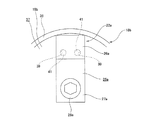
図12〜13は、本発明の実施の形態の1例を示している。本例のセンサ付転がり軸受ユニット1fの場合、キャップ18eを構成するキャップ底板部19eの径方向中央寄り部分{ハブ5(エンコーダ21)の回転軸と同心にならない位置}に、軸方向に貫通し、且つ、軸方向から見た形状が円形状であるナット固定用貫通孔49が形成されている。
又、前記キャップ底板部19eのうちの、前記ナット固定用貫通孔49の周囲で、前記キャップ18eにセンサユニット22eを組み付けた状態で、後述するセンサホルダ25e(取付板部27b)の円周方向両側面に隣接した円周方向2箇所位置に、軸方向に貫通したゴム部材用貫通孔50、50が形成されている。
[ Example of Embodiment]
12 to 13 show an example of an embodiment of the present invention. In the case of the rolling bearing unit with sensor 1f of this example, the cap
Further, in the circumferential direction of a
又、本例の場合も、センサ取付用ナット32bは、前述した参考例の各例と同様に、軸方向に貫通した圧入ナットである。本例の場合、センサ取付用ナット32bは、軸方向内端面に設けられた小径部を、前記キャップ底板部19eの軸方向外側から、前記ナット固定用貫通孔49に圧入する事により固定されている。尚、前記センサ取付用ナット32bの構造は、一般的な圧入ナットの場合とほぼ同様である。又、このセンサ取付用ナット32bは、軸方向に貫通しない構造、即ち、袋ナット状のものを採用する事もできる。
Also in the case of this example, the
又、本例の場合、前記キャップ底板部19eの軸方向内側面のうちの、前記キャップ18eを外輪4に組み付けた状態で、エンコーダ21の被検出面と軸方向に対向する部分の円周方向に離隔した2箇所位置に、径方向に長く且つ軸方向内方に突出した状態で、ゴム製のキャップ側係合凸部48a、48aが加硫接着されている。尚、これら各キャップ側係合凸部48a、48aは、シール部材38と同様のゴム材料から成り、それぞれの径方向外端部を、このシール部材38の軸方向外端部に連続している。
In the case of this example, the circumferential direction of the portion of the inner surface in the axial direction of the cap
又、本例の場合、前記センサ取付用ナット32bを、前記各キャップ側係合凸部48a、48a及び前記シール部材38と同様のゴム材料から成るナット用覆い部51により覆っている。具体的には、このナット用覆い部51は、前記センサ取付用ナット32bの外周面、及び、軸方向外端面(軸方向外端開口部を含む)を覆っている。
この様なナット用覆い部51は、円筒部52と、この円筒部52の軸方向外端開口部を塞ぐ底板部53とから成る、有底円筒状に形成されている。この様なナット用覆い部51は、前記キャップ底板部19eの軸方向外側面、及び、前記センサ取付用ナット32bに、加硫接着により固定されている。この様にして、このセンサ取付用ナット32bが、前記エンコーダ21を設置した内部空間16に露出しない様にしている。この様にして、前記ナット固定用貫通孔49とボルト29aとの螺合部から、水等の異物が侵入した場合でも、この異物が前記内部空間16に侵入する事を阻止している。
In the case of this example, the
Such a
又、前記ナット用覆い部51の円筒部52の円周方向2箇所位置には、このナット用覆い部51と同様のゴム材料から成る連結腕部58、58の、一端部が連続している。この様な各連結腕部58、58は、軸方向内端面を、前記キャップ底板部19eの軸方向外側面に、加硫接着により固定されている。又、前記各連結腕部58、58の他端部と、前記
各キャップ側係合凸部48a、48aの径方向内端部の軸方向外側面とは、前記ゴム部材用貫通孔50、50の内側に充填されたゴム材料により連続している。即ち、本例の場合、前記シール部材38、前記各キャップ側係合凸部48a、48a、前記各連結腕部58、58、及び前記ナット用覆い部51は、同一のゴム材料により一体に形成されている。
尚、前記シール部材38、キャップ側係合凸部48a、及びナット用覆い部51を、別体として設ける事もできる。この際、これら各部材を構成する材料は、同一でも良いし、互いに異ならせても良い。
Further, at two positions in the circumferential direction of the
The
以上の様な構成を有するキャップ18eは、1対の金型(上型及び下型)から成る装置を使用し、これら両金型同士の間に画成されるキャビティ内に、前記センサ取付用ナット32bを固定したキャップ本体37cを配置した状態で、このキャビティ内に、加硫した溶融ゴムを流し込む事により造る事ができる。尚、この様にして前記キャップ18eを造る際、前記センサ取付用ナット32bの雌ねじ部33bの全幅に亙って、予めボルト29aに相当する加硫成形用の雄ねじ材(図示省略)に離型剤を塗布して螺合させておけば、前記センサ取付用ナット32bの内径側に溶融ゴムが流れ込まない様にできる。
The
又、本例の場合、センサユニット22eを構成するセンサホルダ25eのホルダ本体26eの軸方向に関する厚さ寸法T26eと、取付板部27bの軸方向に関する厚さ寸法T27bとを、等しく形成している(T26e=T27b)。即ち、本例の場合、センサホルダ25e全体が、径方向に長い直方体状に形成されている。
又、前記センサホルダ25e(取付板部27b)のうち、前記ナット固定用貫通孔49と整合する位置に、ホルダ側貫通孔54が形成されている。このホルダ側貫通孔54は、軸方向外端寄り部分に形成された小径部55と、この小径部55よりも軸方向内方に形成された大径部56と、これら小径部55と大径部56とを連続した段部57とから成る。
Further, in the present example, the thickness dimension T 26e in the axial direction of the holder
A holder-side through
上述した様な本例の場合、前記ホルダ本体26eを、前記各キャップ側係合凸部48a、48a同士の間に、このホルダ本体26eの円周方向両側面と、これら円周方向両側面と円周方向に対向する前記各キャップ側係合凸部48a、48aの円周方向側面とを円周方向に係合させた状態で配置する。そして、前記センサホルダ25e(ホルダ本体26e及び取付板部27b)の軸方向外端面の全面を、前記キャップ底板部19eの軸方向内側面に当接させた状態で、前記ボルト29aにより前記キャップ18e(キャップ本体37c)に対して支持固定される。具体的には、前記ボルト29aの軸部を前記ホルダ側貫通孔54の小径部55に挿通した状態で、このボルト29aの雄ねじ部42を、前記キャップ底板部19dに固定したセンサ取付用ナット32bの雌ねじ部33bに螺合すると共に、前記ボルト29aの頭部の軸方向外側面を前記段部57に当接させた状態で、このボルト29aを締め付ける事により、前記キャップ18e(キャップ本体37c)に対して支持固定されている。
In the case of this example as described above, the holder
尚、前述した参考例の第4例の場合と同様に、前記各キャップ側係合凸部48a、48aのうちの、前記センサホルダ25eを組み付けた状態で、このセンサホルダ25eに対して、前記ボルト29aの締め付け方向αの後方(図13の左側)となるキャップ側係合凸部48aを省略する事もできる。
又、本例の構造に加えて、前述した参考例の第1例の様に、前記センサホルダ25e(ホルダ本体26e)の軸方向外側面にホルダ側係合凸部41、41(図1、2参照)を形成すると共に、前記キャップ底板部19eの軸方向内側面にキャップ側係合凹部39、39を形成する事もできる。
更に、前記センサホルダ25e(ホルダ本体26e)の軸方向外側面を、前述した参考例の第2例の様に、径方向外半部に形成された非当接部45(図4、5参照)と、径方向内半部に形成された当接部46と、これら非当接部45と当接部46とを連続した段部47とにより構成する事もできる。
As in the case of the fourth example of the reference example described above, the
Further, in addition to the structure of this example, as in the first example of the reference example described above, the holder side engaging
Further, the axially outer surface of the
上述の様な構成を有する本例の場合、前記センサ取付用ナット32bを前記キャップ底板部19eの軸方向外側に設ける構造を採用している為、前記キャップ18eに対する、前記センサユニット22eの固定強度の向上を図れる。その他の構成及び作用効果に就いては、上述した参考例の第2例及び第3例の場合とほぼ同様である。
In the case of this example having the above-described configuration, since the
本発明を実施する場合に、前述した参考例の各例及び実施の形態の1例同士を、適宜組み合わせて実施する事ができる。 When practicing the present invention, each example of the reference example described above and one example of the embodiment can be implemented in appropriate combination.
1、1a、1c、1d、1e、1f 転がり軸受ユニット
2 転がり軸受ユニット
3 回転速度検出装置
4 外輪
5 ハブ
6 転動体
7a、7b 外輪軌道
8 静止側フランジ
9 ナックル
10 ハブ本体
11 内輪
12 かしめ部
13a、13b 内輪軌道
14 回転側フランジ
15 保持器
16 内部空間
17 シールリング
18、18a、18b、18c、18d、18eキャップ
19、19a、19b、19c、19d、19e キャップ底板部
20、20a キャップ円筒部
21 エンコーダ
22、22a、22b、22c、22d、22e センサユニット
23 支持環
24 エンコーダ本体
25、25a、25b、25c、25d、25e センサホルダ
26、26a、26b、26c、26d、26e ホルダ本体
27、27a、27b 取付板部
28 センサ挿入孔
29、29a ボルト
30 ねじ孔
31 ナット固定用凹部
32、32a、32b センサ取付用ナット
33、33a、33b 雌ねじ部
34 センサ
35 嵌合筒部
36 円輪部
37、37a、37b、37c キャップ本体
38 シール部材
39 キャップ側係合凹部
40 ホルダ側貫通孔
41 ホルダ側係合凸部
42 雄ねじ部
43 キャップ側係合凸部
44 ホルダ側係合凹部
45 非当接部
46 当接部
47 段部
48、48a キャップ側係合凸部
49 ナット固定用貫通孔
50 ゴム部材用貫通孔
51 ナット用覆い部
52 円筒部
53 底板部
54 ホルダ側貫通孔
55 小径部
56 大径部
57 段部
58 連結腕部
DESCRIPTION OF SYMBOLS 1, 1a, 1c, 1d, 1e, 1f Rolling bearing unit 2 Rolling bearing unit 3 Rotational speed detection device 4 Outer ring 5 Hub 6 Rolling element 7a, 7b Outer ring track 8 Static side flange 9 Knuckle 10 Hub body 11 Inner ring 12 Caulking part 13a 13b Inner ring raceway 14 Rotating flange 15 Cage 16 Internal space 17 Seal ring 18, 18a, 18b, 18c, 18d, 18e Cap 19, 19a, 19b, 19c, 19d, 19e Cap bottom plate 20, 20a Cap cylinder 21 Encoder 22, 22a, 22b, 22c, 22d, 22e Sensor unit 23 Support ring 24 Encoder body 25, 25a, 25b, 25c, 25d, 25e Sensor holder 26, 26a, 26b, 26c, 26d, 26e Holder body 27, 27a, 27b mounting Plate part 28 Sensor insertion hole 29, 29a Bolt 30 Screw hole 31 Nut fixing recess 32, 32a, 32b Sensor mounting nut 33, 33a, 33b Female thread part 34 Sensor 35 Fitting cylinder part 36 Ring part 37, 37a, 37b 37c Cap body 38 Seal member 39 Cap side engaging recess 40 Holder side through hole 41 Holder side engaging convex portion 42 Male screw portion 43 Cap side engaging convex portion 44 Holder side engaging concave portion 45 Non-contact portion 46 Contact portion 47 Stepped portion 48, 48a Cap side engaging convex portion 49 Nut fixing through hole 50 Rubber member through hole 51 Nut cover portion 52 Cylindrical portion 53 Bottom plate portion 54 Holder side through hole 55 Small diameter portion 56 Large diameter portion 57 Step portion 58 Connecting arms
Claims (3)
外周面に複列の内輪軌道を有し、この外輪の内径側にこの外輪と同心に支持され、外周面のうちでこの外輪の軸方向外端部よりも軸方向外方に突出した部分に車輪を支持する為の回転側フランジを設けたハブと、
前記両外輪軌道と前記両内輪軌道との間に、両列毎に複数個ずつ転動自在に設けられた転動体と、
軸方向内側面の磁気特性を円周方向に関して交互に変化させて成り、前記ハブの軸方向内端部にこのハブと同心に支持された、円環状のエンコーダと、
前記外輪の軸方向内端部に装着されて、この外輪の軸方向内端開口部を塞いだキャップと、
前記エンコーダの被検出面に軸方向に対向した状態で、このエンコーダの被検出面の特性変化に対応して出力信号を変化させるセンサと、このセンサを保持した状態で、前記キャップに支持されたセンサホルダとを備えたセンサユニットと、
を備えたセンサ付転がり軸受ユニットであって、
前記キャップは、キャップ本体と、センサ取付用ナットと、シール部材とを備えたものであり、
このうちのキャップ本体は、非磁性金属板により有底円筒状に造られたもので、前記外輪の軸方向内端部に内嵌固定されたキャップ円筒部と、このキャップ円筒部の軸方向内端開口を塞ぐキャップ底板部とを有するものであり、
前記センサ取付用ナットは、前記キャップ底板部に設けられており、
前記シール部材は、ゴムにより一体に形成されたもので、前記キャップ円筒部の外周面に全周に亙り、加硫接着により固定されており、
前記センサユニットは、前記センサホルダのうちの前記センサを保持した部分であるホルダ本体の少なくとも一部の軸方向外側面を、前記キャップ底板部の軸方向内側面に当接させると共に、前記ホルダ本体の円周方向側面により構成されたホルダ側係合部と、前記シール部材と一体に形成されたゴム製で、このキャップ底板部の軸方向内側面に加硫接着されたキャップ側係合部とを、円周方向に係合させた状態で、前記センサ取付用ナットに螺合したボルトにより前記キャップに結合固定されており、
前記センサホルダの軸方向外側面が、前記センサと軸方向に重畳して、前記キャップ底板部の軸方向内側面と当接しない非当接部と、前記ホルダ側係合部が形成されて、前記キャップ底板部に押し付けられる当接部と、前記非当接部とこの当接部とを連続した段部とにより構成されている、
事を特徴とするセンサ付転がり軸受ユニット。 An outer ring having a double-row outer ring raceway on the inner peripheral surface and not rotating during use;
The outer ring has a double-row inner ring raceway and is supported concentrically with the outer ring on the inner diameter side of the outer ring, and on the part of the outer circumferential surface that protrudes outward in the axial direction from the axial outer end of the outer ring. A hub provided with a rotation side flange for supporting the wheel;
Between the both outer ring raceways and the both inner ring raceways, a plurality of rolling elements provided so as to be freely rollable for each row,
An annular encoder that is formed by alternately changing the magnetic properties of the inner surface in the axial direction with respect to the circumferential direction, and is supported concentrically with the hub at the inner end in the axial direction of the hub;
A cap that is attached to the axially inner end of the outer ring and closes the axially inner end opening of the outer ring;
A sensor that changes an output signal in response to a change in the characteristics of the detected surface of the encoder while facing the detected surface of the encoder in the axial direction, and is supported by the cap while holding the sensor. A sensor unit comprising a sensor holder;
A rolling bearing unit with a sensor comprising:
The cap includes a cap body, a sensor mounting nut, and a seal member.
The cap body is made of a non-magnetic metal plate and has a bottomed cylindrical shape. The cap body is fitted and fixed to the inner end of the outer ring in the axial direction. And a cap bottom plate portion that closes the end opening,
The sensor mounting nut is provided on the cap bottom plate,
The seal member is integrally formed of rubber, and is fixed to the outer peripheral surface of the cap cylindrical portion over the entire circumference by vulcanization adhesion.
The sensor unit abuts at least a part of an axially outer surface of a holder main body, which is a part of the sensor holder holding the sensor, in contact with an axially inner side surface of the cap bottom plate part, and the holder main body And a cap side engaging portion made of rubber integrally formed with the seal member and vulcanized and bonded to the inner side surface in the axial direction of the cap bottom plate portion; Are coupled and fixed to the cap by a bolt screwed to the sensor mounting nut in a state of being engaged in the circumferential direction ,
An axially outer surface of the sensor holder is overlapped with the sensor in the axial direction, and a non-contact portion that does not contact the axial inner surface of the cap bottom plate portion, and the holder-side engagement portion are formed, The contact portion is pressed against the cap bottom plate portion, and the non-contact portion and the contact portion are configured to be a continuous step portion.
This is a rolling bearing unit with sensor.
前記センサ取付用ナットの外周面及び軸方向外端面が、前記シール部材及び前記キャップ側係合部と一体に形成された、ゴム製のナット覆い部により覆われている、請求項1に記載したセンサ付転がり軸受ユニット。 The sensor mounting nut is directly fixed to the outside of the cap bottom plate portion in the axial direction by press-fitting and fixing the axial inner end portion to a nut fixing through hole formed in the cap bottom plate portion,
The outer peripheral surface and the axially outer end face of the sensor mounting nut, the sealing member and integrally formed with the cap side engaging portion, is covered by a rubber nut covering portion, according to claim 1 Rolling bearing unit with sensor.
外周面に複列の内輪軌道を有し、この外輪の内径側にこの外輪と同心に支持され、外周面のうちでこの外輪の軸方向外端部よりも軸方向外方に突出した部分に車輪を支持する為の回転側フランジを設けたハブと、
前記両外輪軌道と前記両内輪軌道との間に、両列毎に複数個ずつ転動自在に設けられた転動体と、
軸方向内側面の磁気特性を円周方向に関して交互に変化させて成り、前記ハブの軸方向内端部にこのハブと同心に支持された、円環状のエンコーダと、
前記外輪の軸方向内端部に装着されて、この外輪の軸方向内端開口部を塞いだキャップと、
前記エンコーダの被検出面に軸方向に対向した状態で、このエンコーダの被検出面の特性変化に対応して出力信号を変化させるセンサと、このセンサを保持した状態で、前記キャップに支持されたセンサホルダとを備えたセンサユニットと、
を備えたセンサ付転がり軸受ユニットであって、
前記キャップは、キャップ本体と、センサ取付用ナットと、シール部材とを備えたものであり、
このうちのキャップ本体は、非磁性金属板により有底円筒状に造られたもので、前記外輪の軸方向内端部に内嵌固定されたキャップ円筒部と、このキャップ円筒部の軸方向内端開口を塞ぐキャップ底板部とを有するものであり、
前記センサ取付用ナットは、軸方向内端部を、前記キャップ底板部に形成されたナット固定用貫通孔に圧入固定する事により、このキャップ底板部の軸方向外側に直接固定されており、
前記シール部材は、ゴムにより一体に形成されたもので、前記キャップ円筒部の外周面に全周に亙り、加硫接着により固定されており、
前記センサユニットは、前記センサホルダのうちの前記センサを保持した部分であるホルダ本体の少なくとも一部の軸方向外側面を、前記キャップ底板部の軸方向内側面に当接させると共に、前記ホルダ本体の円周方向側面により構成されたホルダ側係合部と、前記シール部材と一体に形成されたゴム製で、このキャップ底板部の軸方向内側面に加硫接着されたキャップ側係合部とを、円周方向に係合させた状態で、前記センサ取付用ナットに螺合したボルトにより前記キャップに結合固定されており、
前記センサ取付用ナットの外周面及び軸方向外端面が、前記シール部材及び前記キャップ側係合部と一体に形成された、ゴム製のナット覆い部により覆われている、
事を特徴とするセンサ付転がり軸受ユニット。 An outer ring having a double-row outer ring raceway on the inner peripheral surface and not rotating during use;
The outer ring has a double-row inner ring raceway and is supported concentrically with the outer ring on the inner diameter side of the outer ring, and on the part of the outer circumferential surface that protrudes outward in the axial direction from the axial outer end of the outer ring. A hub provided with a rotation side flange for supporting the wheel;
Between the both outer ring raceways and the both inner ring raceways, a plurality of rolling elements provided so as to be freely rollable for each row,
An annular encoder that is formed by alternately changing the magnetic properties of the inner surface in the axial direction with respect to the circumferential direction, and is supported concentrically with the hub at the inner end in the axial direction of the hub;
A cap that is attached to the axially inner end of the outer ring and closes the axially inner end opening of the outer ring;
A sensor that changes an output signal in response to a change in the characteristics of the detected surface of the encoder while facing the detected surface of the encoder in the axial direction, and is supported by the cap while holding the sensor. A sensor unit comprising a sensor holder;
A rolling bearing unit with a sensor comprising:
The cap includes a cap body, a sensor mounting nut, and a seal member.
The cap body is made of a non-magnetic metal plate and has a bottomed cylindrical shape. The cap body is fitted and fixed to the inner end of the outer ring in the axial direction. And a cap bottom plate portion that closes the end opening,
The sensor mounting nut is directly fixed to the outside of the cap bottom plate portion in the axial direction by press-fitting and fixing the axial inner end portion to a nut fixing through hole formed in the cap bottom plate portion,
The seal member is integrally formed of rubber, and is fixed to the outer peripheral surface of the cap cylindrical portion over the entire circumference by vulcanization adhesion.
The sensor unit abuts at least a part of an axially outer surface of a holder main body, which is a part of the sensor holder holding the sensor, in contact with an axially inner side surface of the cap bottom plate part, and the holder main body And a cap side engaging portion made of rubber integrally formed with the seal member and vulcanized and bonded to the inner side surface in the axial direction of the cap bottom plate portion; Are coupled and fixed to the cap by a bolt screwed to the sensor mounting nut in a state of being engaged in the circumferential direction ,
The outer peripheral surface and the axially outer end surface of the sensor mounting nut are covered with a rubber nut cover portion formed integrally with the seal member and the cap side engaging portion.
This is a rolling bearing unit with sensor.
Priority Applications (1)
| Application Number | Priority Date | Filing Date | Title |
|---|---|---|---|
| JP2018016501A JP6555366B2 (en) | 2018-02-01 | 2018-02-01 | Rolling bearing unit with sensor |
Applications Claiming Priority (1)
| Application Number | Priority Date | Filing Date | Title |
|---|---|---|---|
| JP2018016501A JP6555366B2 (en) | 2018-02-01 | 2018-02-01 | Rolling bearing unit with sensor |
Related Parent Applications (1)
| Application Number | Title | Priority Date | Filing Date |
|---|---|---|---|
| JP2014101835A Division JP6500345B2 (en) | 2014-05-15 | 2014-05-15 | Sensor and rolling bearing unit |
Publications (2)
| Publication Number | Publication Date |
|---|---|
| JP2018076969A JP2018076969A (en) | 2018-05-17 |
| JP6555366B2 true JP6555366B2 (en) | 2019-08-07 |
Family
ID=62148979
Family Applications (1)
| Application Number | Title | Priority Date | Filing Date |
|---|---|---|---|
| JP2018016501A Expired - Fee Related JP6555366B2 (en) | 2018-02-01 | 2018-02-01 | Rolling bearing unit with sensor |
Country Status (1)
| Country | Link |
|---|---|
| JP (1) | JP6555366B2 (en) |
Families Citing this family (1)
| Publication number | Priority date | Publication date | Assignee | Title |
|---|---|---|---|---|
| JP7101371B2 (en) * | 2020-01-31 | 2022-07-15 | 株式会社 三光 | Dry-type aluminum alloy sorting method and sorting system from dismantled aluminum sash scraps |
Family Cites Families (2)
| Publication number | Priority date | Publication date | Assignee | Title |
|---|---|---|---|---|
| JP2012232708A (en) * | 2011-05-09 | 2012-11-29 | Nsk Ltd | Wheel-supporting rolling bearing unit |
| JP2013117455A (en) * | 2011-12-05 | 2013-06-13 | Ntn Corp | Wheel bearing apparatus with rotation speed detection device |
-
2018
- 2018-02-01 JP JP2018016501A patent/JP6555366B2/en not_active Expired - Fee Related
Also Published As
| Publication number | Publication date |
|---|---|
| JP2018076969A (en) | 2018-05-17 |
Similar Documents
| Publication | Publication Date | Title |
|---|---|---|
| JP5169886B2 (en) | Rolling bearing unit with rotational speed detector | |
| US7126328B2 (en) | Rolling bearing unit with rotational speed detecting device | |
| JP5327077B2 (en) | Rolling bearing unit for wheel support with encoder | |
| JP5327369B2 (en) | Rolling bearing unit for driven wheels with rotational speed detector | |
| JP2005042866A5 (en) | ||
| WO2017150562A1 (en) | Bearing device for vehicle wheel | |
| JP6256122B2 (en) | Rolling bearing unit with rotational speed detector | |
| JP6555366B2 (en) | Rolling bearing unit with sensor | |
| JP5115967B2 (en) | Wheel bearing device with rotation speed detector | |
| JP2008175382A (en) | Rolling bearing unit for supporting wheel with rotating speed detector | |
| JP4221944B2 (en) | Sealing device | |
| WO2017159804A1 (en) | Wheel bearing device | |
| JP6349954B2 (en) | Bearing unit with rotation speed detector | |
| JP6500345B2 (en) | Sensor and rolling bearing unit | |
| JP2009024767A (en) | Bearing device having rotation speed detecting device for use in wheel | |
| JP2004052832A (en) | Rolling bearing device | |
| JP4239669B2 (en) | Rolling bearing unit for wheel support | |
| JP2003042175A (en) | Rolling bearing unit with encoder | |
| JP4952035B2 (en) | Manufacturing method of seal ring with encoder and rolling bearing unit with encoder | |
| JP2015166612A (en) | Bearing unit with rotating speed detection device | |
| JP2008286267A (en) | Bearing device for wheel equipped with rotation speed detection device | |
| JP2019052738A (en) | Hub unit bearing | |
| JP6287455B2 (en) | Rolling bearing unit with rotational speed detector | |
| JP6394051B2 (en) | Rolling bearing unit with rotational speed detector | |
| JP6417701B2 (en) | Rolling bearing unit with rotational speed detector |
Legal Events
| Date | Code | Title | Description |
|---|---|---|---|
| A521 | Request for written amendment filed |
Free format text: JAPANESE INTERMEDIATE CODE: A523 Effective date: 20180221 |
|
| A621 | Written request for application examination |
Free format text: JAPANESE INTERMEDIATE CODE: A621 Effective date: 20180221 |
|
| A977 | Report on retrieval |
Free format text: JAPANESE INTERMEDIATE CODE: A971007 Effective date: 20181221 |
|
| A131 | Notification of reasons for refusal |
Free format text: JAPANESE INTERMEDIATE CODE: A131 Effective date: 20190108 |
|
| A521 | Request for written amendment filed |
Free format text: JAPANESE INTERMEDIATE CODE: A523 Effective date: 20190214 |
|
| TRDD | Decision of grant or rejection written | ||
| A01 | Written decision to grant a patent or to grant a registration (utility model) |
Free format text: JAPANESE INTERMEDIATE CODE: A01 Effective date: 20190611 |
|
| A61 | First payment of annual fees (during grant procedure) |
Free format text: JAPANESE INTERMEDIATE CODE: A61 Effective date: 20190624 |
|
| R150 | Certificate of patent or registration of utility model |
Ref document number: 6555366 Country of ref document: JP Free format text: JAPANESE INTERMEDIATE CODE: R150 |
|
| LAPS | Cancellation because of no payment of annual fees |