JP6554569B2 - Impeller lift type shot peening system - Google Patents
Impeller lift type shot peening system Download PDFInfo
- Publication number
- JP6554569B2 JP6554569B2 JP2018012811A JP2018012811A JP6554569B2 JP 6554569 B2 JP6554569 B2 JP 6554569B2 JP 2018012811 A JP2018012811 A JP 2018012811A JP 2018012811 A JP2018012811 A JP 2018012811A JP 6554569 B2 JP6554569 B2 JP 6554569B2
- Authority
- JP
- Japan
- Prior art keywords
- coil spring
- impeller
- chamber
- shot peening
- shot
- Prior art date
- Legal status (The legal status is an assumption and is not a legal conclusion. Google has not performed a legal analysis and makes no representation as to the accuracy of the status listed.)
- Active
Links
- 238000005480 shot peening Methods 0.000 title claims description 97
- 230000007246 mechanism Effects 0.000 claims description 80
- 238000004804 winding Methods 0.000 claims description 55
- 230000003028 elevating effect Effects 0.000 claims description 21
- 238000007373 indentation Methods 0.000 description 16
- 238000003825 pressing Methods 0.000 description 16
- 239000011248 coating agent Substances 0.000 description 11
- 238000000576 coating method Methods 0.000 description 11
- 230000003746 surface roughness Effects 0.000 description 7
- 239000000725 suspension Substances 0.000 description 7
- 210000000078 claw Anatomy 0.000 description 6
- 238000010422 painting Methods 0.000 description 5
- 238000000034 method Methods 0.000 description 4
- 229910000639 Spring steel Inorganic materials 0.000 description 3
- 238000010438 heat treatment Methods 0.000 description 3
- 238000012423 maintenance Methods 0.000 description 3
- 238000004519 manufacturing process Methods 0.000 description 3
- 235000019592 roughness Nutrition 0.000 description 3
- 230000006835 compression Effects 0.000 description 2
- 238000007906 compression Methods 0.000 description 2
- 239000003973 paint Substances 0.000 description 2
- 239000002245 particle Substances 0.000 description 2
- 238000005192 partition Methods 0.000 description 2
- 238000000137 annealing Methods 0.000 description 1
- 238000009503 electrostatic coating Methods 0.000 description 1
- 239000012530 fluid Substances 0.000 description 1
- 238000007689 inspection Methods 0.000 description 1
- 230000002452 interceptive effect Effects 0.000 description 1
- JEIPFZHSYJVQDO-UHFFFAOYSA-N iron(III) oxide Inorganic materials O=[Fe]O[Fe]=O JEIPFZHSYJVQDO-UHFFFAOYSA-N 0.000 description 1
- 239000000463 material Substances 0.000 description 1
- 230000007935 neutral effect Effects 0.000 description 1
- 230000003449 preventive effect Effects 0.000 description 1
- 230000000630 rising effect Effects 0.000 description 1
- 239000002436 steel type Substances 0.000 description 1
- 239000000126 substance Substances 0.000 description 1
- 238000005496 tempering Methods 0.000 description 1
Images


Landscapes
- Springs (AREA)
- Wire Processing (AREA)
Description
この発明は、コイルばねにショットピーニングを行なうためのインペラ昇降式ショットピーニング装置に関する。 The present invention relates to an impeller elevating type shot peening apparatus for performing shot peening on a coil spring.
車両の懸架装置の懸架ばね等に使用されるコイルばねの耐久性を高めるために、ショットピーニングによってコイルばねの表面付近に圧縮残留応力を付与することが知られている。従来のショットピーニング装置は、例えば特許文献1に開示されているように、コイルばねを連続的に搬送しながら、遠心式加速装置(インペラ)からコイルばねに向けてショットを投射するように構成されている。また特許文献2に記載されているように、コイルばねを圧縮し、応力を与えた状態でショットピーニングを行なういわゆるストレスピーニングによって、より大きな圧縮残留応力を生じさせるショットピーニング方法も知られている。
In order to enhance the durability of a coil spring used for a suspension spring of a vehicle suspension system, it is known to apply compressive residual stress near the surface of the coil spring by shot peening. A conventional shot peening apparatus is configured to project a shot from a centrifugal accelerator (impeller) toward a coil spring while conveying the coil spring continuously as disclosed in, for example,
特許文献1のようにコイルばねを単に一方向に連続的に搬送しながらショットを一方向から投射する連続式ショットピーニング装置では、コイルばねの表面全体にさらに大きな圧縮残留応力を生じさせる上で改善の余地があった。特許文献2のようにコイルばねを圧縮した状態でショットピーニングを行なうことも提案されているが、圧縮されたコイルばねは、自由状態のコイルばねよりも素線間の距離が狭くなるため、一定の方向から投射されるショットが素線間に入りにくくなる。このためコイルばねの外面側にはショットが十分当るが、コイルばねの内面側には素線の影となる箇所が生じ、その箇所ではショットが十分に当らないため圧縮残留応力が不足してしまい、所望の耐久性を発揮することができないことがあった。
In the continuous shot peening device that projects a shot from one direction while continuously conveying the coil spring in one direction as in
従って本発明の目的は、コイルばねの耐久性を向上させる上で効果のある圧縮残留応力を形成できるインペラ昇降式ショットピーニング装置を提供することにある。 Accordingly, an object of the present invention is to provide an impeller elevating type shot peening apparatus capable of forming a compressive residual stress effective in improving the durability of a coil spring.
1つの実施形態のインペラ昇降式ショットピーニング装置は、ハウジングと、ワーク保持機構と、ストレス付与機構と、自転機構と、投射機構と、昇降機構とを具備している。前記ハウジングは、コイルばねが出し入れされるワーク出入口を有する第1のチャンバと、該コイルばねにショットピーニングを行なう第2のチャンバとを備えている。前記ワーク保持機構は、前記コイルばねの下側の座巻部に接する下側の座巻支持部と、前記コイルばねの上側の座巻部に接する上側の座巻支持部とを有し、前記下側の座巻支持部と前記上側の座巻支持部との間に前記コイルばねを立てた姿勢で保持する。前記ストレス付与機構は、前記第2のチャンバ内に搬入された前記コイルばねを前記下側の座巻支持部と前記上側の座巻支持部との間で上下方向に圧縮する。前記自転機構は、前記第2のチャンバ内の前記コイルばねを垂直軸回りに自転させる。前記投射機構は、前記第2のチャンバ内の前記コイルばねが前記ストレス付与機構によって圧縮されかつ前記自転機構によって回転している状態において該コイルばねに向けてショットを投射する。前記昇降機構は、前記コイルばねに前記ショットが投射されている状態において前記投射機構を前記コイルばねが圧縮され長さが小さくなった方向と同じ上下方向に移動させる。前記投射機構のインペラユニットは、インペラと、前記インペラにショットを供給するディストリビュータと、前記インペラを回転させるモータとを有する。前記昇降機構は、前記ハウジングの側部に設けられ上下方向に延びるガイド部材と、前記インペラユニットを前記ガイド部材に沿って上下方向に移動させる駆動源とを有する。 An impeller elevating type shot peening apparatus according to one embodiment includes a housing, a work holding mechanism, a stress applying mechanism, a rotation mechanism, a projection mechanism, and an elevating mechanism. The housing includes a first chamber having a work inlet / outlet through which a coiled spring is inserted and withdrawn, and a second chamber for shot peening the coiled spring. The work holding mechanism includes a lower end winding support portion that contacts a lower end winding portion of the coil spring, and an upper end winding support portion that contacts an upper end winding portion of the coil spring, The coil spring is held in an upright position between the lower end-winding support and the upper end-winding support. The stress applying mechanism vertically compresses the coil spring carried into the second chamber between the lower end-winding support and the upper end-winding support. The rotation mechanism rotates the coil spring in the second chamber about a vertical axis. The projection mechanism projects a shot toward the coil spring in a state where the coil spring in the second chamber is compressed by the stress applying mechanism and rotated by the rotation mechanism. The elevating mechanism moves the projection mechanism in the same vertical direction as the direction in which the coil spring is compressed and the length is reduced in a state where the shot is projected onto the coil spring . The impeller unit of the projection mechanism has an impeller, a distributor for supplying a shot to the impeller, and a motor for rotating the impeller. The elevating mechanism has a guide member provided on the side of the housing and extending in the vertical direction, and a drive source for moving the impeller unit in the vertical direction along the guide member .
前記ワーク保持機構が、前記下側の座巻支持部が配置されたターンテーブルと、前記下側の座巻支持部が前記第1のチャンバと前記第2のチャンバとにわたって往復するよう前記ターンテーブルを公転軸まわりに回転させる公転機構とを備えていてもよい。さらに前記ワーク保持機構が、一対の前記下側の座巻支持部を有し、これら下側の座巻支持部が前記ターンテーブル上に前記公転軸を中心として180°対称位置に配置され、前記ターンテーブルが前記公転機構によって180°ずつ回転するように構成されてもよい。 The work holding mechanism includes a turntable on which the lower end winding support is disposed, and the turntable so that the lower end winding support reciprocates between the first chamber and the second chamber. And a revolution mechanism that rotates the revolution shaft around the revolution axis. Further, the work holding mechanism has a pair of lower end winding support portions, and these lower end winding support portions are arranged on the turntable at a 180 ° symmetrical position around the revolution axis, The turntable may be configured to rotate 180 degrees by the revolving mechanism.
また前記投射機構が、前記第2のチャンバ内の前記コイルばねの斜め上方からショットを投射するとともに該コイルばねに対して上下方向に移動する第1のインペラユニットと、前記コイルばねの斜め下方からショットを投射するとともに該コイルばねに対して上下方向に移動する第2のインペラユニットとを含んでいてもよい。 Further, the projection mechanism projects a shot obliquely from above the coil spring in the second chamber, and the first impeller unit moves in the vertical direction with respect to the coil spring; A second impeller unit that projects a shot and moves in the vertical direction with respect to the coil spring may be included.
さらに前記ハウジングが、前記第1のインペラユニットを前記第2のチャンバに対し開位置と閉位置とに回動可能に支持する第1のヒンジ機構と、前記第2のインペラユニットを前記第2のチャンバに対し開位置と閉位置とに回動可能に支持する第2のヒンジ機構とを備えていてもよい。 The housing further includes a first hinge mechanism that rotatably supports the first impeller unit in an open position and a closed position with respect to the second chamber, and the second impeller unit in the second chamber. You may provide the 2nd hinge mechanism supported so that rotation to an open position and a closed position with respect to a chamber is possible.
1つの実施形態に係るコイルばねは、螺旋形に成形された素線からなり両端に座巻部を有したコイルばねであって、前記座巻部の表面の一部に形成された第1のショットピーニング圧痕からなる第1粗面部と、該第1粗面部を除く前記素線の表面全体に形成され、前記第1粗面部とは表面粗さが異なる第2のショットピーニグ圧痕からなる第2粗面部とを具備している。前記第1粗面部の一例は、前記座巻部の巻き方向に間隔を存して複数個所に島状に点在する。
A coil spring according to one embodiment is a coil spring formed of a helically shaped wire and having end turns at both ends, the first formed on a part of the surface of the end turns. A first rough surface portion formed of a shot peening indentation and a second shot peening indentation formed on the entire surface of the wire except the first rough surface portion and having a surface roughness different from that of the first
本発明のインペラ昇降式ショットピーニング装置によれば、耐久性の向上に効果がある圧縮残留応力をコイルばねに形成することができる。座巻部の一部で座巻支持部が接する箇所には第1のショットピーニング圧痕からなる第1粗面部が島状に残る。しかしこの第1粗面部は応力的に余裕のある座巻部に形成されるため、第1粗面部が存在していても耐久性に関して不利になることはない。コイルばねを塗装する前に第1粗面部の有無を確認すれば、第1のショットピーニングと第2のショットピーニングとによる二段ショットピーニングが行なわれたか否かを目視によって確認することが可能である。 According to the impeller elevating type shot peening apparatus of the present invention, compressive residual stress that is effective in improving durability can be formed in the coil spring. The first rough surface portion made of the first shot peening indentation remains in an island shape at a part of the end winding portion where the end winding support portion contacts. However, since the first rough surface portion is formed in the end winding portion having a sufficient margin in terms of stress, there is no disadvantage regarding durability even if the first rough surface portion exists. If the presence or absence of the first rough surface portion is confirmed before coating the coil spring, it is possible to visually confirm whether or not the two-step shot peening by the first shot peening and the second shot peening has been performed. is there.
以下に1つの実施形態に係るコイルばねとインペラ昇降式ショットピーニング装置について、図1から図10を参照して説明する。 A coil spring and an impeller elevating type shot peening apparatus according to one embodiment will be described below with reference to FIGS.
図1は、塗装されたコイルばね10の一例を示している。図2は、塗装されたコイルばね10の一部(図1中にS1で示す部分)の拡大図である。コイルばね10は、螺旋形に巻かれた素線(ワイヤ)11を有している。素線11の表面は、錆止めの塗膜(塗料の皮膜)12によって覆われている。コイルばね10の両端にそれぞれ座巻部10a,10bが形成されている。座巻部10a,10b間には、圧縮荷重の大きさに応じて撓む螺旋形の有効部10cが形成されている。
FIG. 1 shows an example of a painted
図1において下側の座巻部10aは、素線11の下端から1巻未満の巻数(例えば0.6巻程度)で形成され、例えば車両用懸架装置では下側のばね座に接する。図1において上側の座巻部10bは、素線11の上端から1巻未満の巻数(例えば0.6巻程度)で形成され、例えば車両用懸架装置では上側のばね座に接する。コイルばね10に圧縮の荷重が負荷されて有効部10cが撓むと、素線11にねじりの応力が生じる。
In FIG. 1, the lower
コイルばね10の一例は円筒コイルばねであるが、懸架装置の仕様に応じて、たる形コイルばね、鼓形コイルばね、テーパコイルばね、不等ピッチコイルばねなど、種々の形態のコイルばねが採用される。素線11の一例は断面が円形のばね鋼からなる。自動車の懸架用コイルばねの場合、素線11の線径は8〜21mmが主流である。しかしこれ以外の線径であっても勿論かまわない。
An example of the
素線11の材料であるばね鋼の種類は特に限定されないが、例えば米国の“Society of Automotive Engineers”に準拠するSAE9254が挙げられる。SAE9254の化学成分(mass%)は、C:0.51〜0.59、Si:1.20〜1.60、Mn:0.60〜0.80、Cr:0.60〜0.80、S:最大0.040、P:最大0.030、残部Feである。鋼種の他の例が超高強度ばね鋼であってもよい。
Although the kind of spring steel which is the material of the
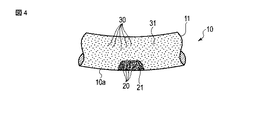
図3は、塗装前(塗膜が形成される前)のコイルばね10を示している。図4は、塗装前のコイルばね10の一部(図3中にS2で示した部分)の拡大図である。図3と図4に示されるように、塗装前の座巻部10a,10bの一部に、それぞれ、多数の微視的凹凸である第1のショットピーニング圧痕20からなる第1粗面部21(図3と図4に模式的に濃い梨地模様で示す)が形成されている。
FIG. 3 shows the
第1粗面部21は、下側の座巻部10aと上側の座巻部10bとに、それぞれ複数個所(3〜4箇所)形成されている。これら第1粗面部21は、各座巻部10a,10bの巻き方向に間隔を存してそれぞれ島状に点在している。第1のショットピーニング圧痕20は、以下に説明する第1のショットピーニング工程において、例えば連続式ショットピーニング装置40(図6に示す)によって第1のショットSH1をコイルばね10に投射することにより、素線11の表面全体に形成される。素線11の表面全体のうち、第1粗面部21を除く素線11の表面に、多数の微視的凹凸である第2のショットピーニング圧痕30からなる第2粗面部31(図3と図4に模式的に薄い梨地模様で示す)が形成されている。
The first
第2のショットピーニング圧痕30は、後に詳しく説明するインペラ昇降式ショットピーニング装置50によって、第1粗面部21を除く素線11の表面全体に形成される。第2粗面部31の表面粗さは第1粗面部21の表面粗さとは異なっている。表面粗さはショットピーニングの条件によって左右されるため一概には言えないが、例えば第1粗面部21の最大高さが30〜50μm、第2粗面部31の最大高さが20〜30μmというように、第2粗面部31の粗さが第1粗面部21の粗さよりも小さい。
The second
図5は、コイルばね10の製造工程の一例を示している。図5中の成形工程S1において、コイリングマシンを用いて素線11が螺旋形に成形される。熱処理工程S2では、成形工程S1によって素線11に生じた歪み応力を除去するために、焼戻しと焼鈍がなされる。例えば熱処理工程S2において素線11が例えば400〜450℃程度に加熱されたのち徐冷される。ホットセッチング工程S3では、熱処理工程S2の余熱を利用して、温間(250〜350℃)でホットセッチングが行なわれる。ホットセッチングは温間のコイルばね10に加圧装置によって軸線方向の荷重が所定時間付与される。
FIG. 5 shows an example of the manufacturing process of the
さらに第1のショットピーニング工程S4において、温間で第1のショットピーニングが実施される。第1のショットピーニング工程S4では、第1のショット(例えば粒径が1.1mmのラージサイズのカットワイヤ)が使用される。ただしこれ以外のショットサイズ(例えば0.87〜1.2mm)であってもよい。この第1のショットを、図6に模式的に示す連続式ショットピーニング装置40によって、例えば250〜300℃の処理温度のもとで、コイルばね10の表面全体に投射する。第1のショットの投射速度は、例えば77m/secである。
Furthermore, in the first shot peening step S4, the first shot peening is carried out warmly. In the first shot peening step S4, a first shot (for example, a large cut wire having a particle size of 1.1 mm) is used. However, other shot sizes (for example, 0.87 to 1.2 mm) may be used. The first shot is projected onto the entire surface of the
図6に示された連続式ショットピーニング装置40の一例は、一対のローラ41,42上に載置されたコイルばね10を矢印Fで示す方向に連続的に移動させつつ、ローラ41,42によってコイルばね10を回転させながら、遠心式加速装置(インペラ)43から第1のショットSH1をコイルばね10に投射するように構成されている。
An example of the continuous
この第1のショットピーニングによって、コイルばね10の表面から比較的深い位置まで圧縮残留応力が形成される。しかも素線11の表面に形成されていた酸化皮膜(熱処理による黒皮)が第1のショットピーニングによって除去されるとともに、素線11の表面に第1のショットピーニング圧痕20(図4に一部を模式的に示す)が形成されるため、後に行なわれる塗装工程S7において塗料が素線11に付着しやすくなる。
By this first shot peening, compressive residual stress is formed from the surface of the
図5中の第2のショットピーニング工程S5では、図7から図10に示すインペラ昇降式ショットピーニング装置50によって、第1のショットピーニング工程S4よりも低い温度(例えば200〜250℃)のもとで、コイルばね10を圧縮した状態で第2のショットピーニング(温間ストレスショットピーニング)が行なわれる。第2のショットピーニング工程S5では、第1のショットピーニング工程S4で使用した第1のショットSH1よりもサイズの小さい第2のショットSH2(例えば粒径が0.4〜0.7mmのスモールサイズのカットワイヤ)がコイルばね10の表面全体に投射される。
In the second shot peening step S5 in FIG. 5, the impeller lifting type shot
第2のショットピーニング工程S5(温間ストレスショットピーニング)によって、素線11の表面付近の圧縮残留応力の絶対値を増加させることができる。しかも温間温度域に加熱されたコイルばね10が圧縮された状態でスモールサイズの第2のショットSH2が投射されるため、表面付近の圧縮残留応力を効果的に増加させることができるとともに、素線11の表面の粗さが改善される(表面粗さが小さくなる)ため、コイルばね10の耐久性をさらに向上させることができる。
By the second shot peening step S5 (warm stress shot peening), the absolute value of the compressive residual stress near the surface of the
第2のショットピーニング工程S5が終了したのち、必要に応じてセッチング工程S6を実施することにより、コイルばねの無荷重時の長さ(自由長)を調整する。このセッチング工程S6によって、コイルばねのクリープ性(耐へたり性)を向上させることもできる。なお、セッチング工程S6を省略してもよい。次いで、塗装工程S7において、コイルばね全体に防錆塗料が静電塗装等によって塗布される。最後に品質検査が行なわれてコイルばね10の完成となる。
After the second shot peening step S5 is completed, the setting step S6 is performed as necessary to adjust the length (free length) of the coil spring when there is no load. The creeping property (sag resistance) of the coil spring can be improved by the setting step S6. The setting step S6 may be omitted. Next, in the coating step S7, a rust preventive paint is applied to the entire coil spring by electrostatic coating or the like. Finally, quality inspection is performed and the
図7から図10は、第2のショットピーニング工程S5に使用されるインペラ昇降式ショットピーニング装置50を示している。図7は、インペラ昇降式ショットピーニング装置50の一部を示す正面図、図8は縦断面図、図8と図9はそれぞれ横断面図である。
FIGS. 7 to 10 show the impeller elevating type shot
インペラ昇降式ショットピーニング装置50は、コイルばね(ワーク)10を収容するハウジング51と、コイルばね10をほぼ垂直に立てた姿勢で保持するワーク保持機構52と、コイルばね10に向けてショットSH2を投射するための第1のインペラユニット55および第2のインペラユニット56を含む投射機構57と、インペラユニット55,56を上下方向に移動させる第1の昇降機構58および第2の昇降機構59とを有している。
The impeller lifting type shot
第1の昇降機構58と第2の昇降機構59の一例は、それぞれ、コントローラによって回転が制御されるサーボモータ58a,59a(図8に示す)とボールねじ58b,59bなどからなり、サーボモータ58a,59aの回転方向と回転量に応じてインペラユニット55,56をそれぞれ独立して上下方向に一定のストロークY1,Y2で移動させることができるように構成されている。
One example of the
図8と図9に示されるように、ハウジング51の内部に、第1のチャンバ61と、第2のチャンバ62と、これらチャンバ61,62間に位置する中間チャンバ63,64とが形成されている。第1のチャンバ61には、ハウジング51の外側からコイルばね10を第1のチャンバ61内に出し入れするための開口であるワーク出入口65が形成されている。
As shown in FIGS. 8 and 9, a
第2のチャンバ62には、投射機構57を構成する第1のインペラユニット55と第2のインペラユニット56の各投射口55a,56aが配置され、これら投射口55a,56aからコイルばね10に向けてショットSH2が投射されるようになっている。つまり第2のチャンバ62内にて、コイルばね10にショットSH2を投射することによって第2のショットピーニングが行なわれる。
In the
図9と図10に示されるように、第1のチャンバ61と中間チャンバ63,64との間に隔壁70,71が設けられている。第2のチャンバ62と中間チャンバ63,64との間にも隔壁72,73が設けられている。さらに中間チャンバ63,64には、第2のチャンバ62内に投射されたショットSH2が第1のチャンバ61に向かうことを防ぐシール壁74,75が形成されている。
As shown in FIGS. 9 and 10,
図7に示すようにワーク保持機構52は、垂直方向に延びる公転軸X1を中心に回転するターンテーブル79と、ターンテーブル79を公転軸X1まわりに第1の方向R1と第2の方向R2(図9に示す)とに180°ずつ間欠的に回動させるモータを備えた公転機構80(図7に示す)と、ターンテーブル79上に配置された一対のワークホルダ81,82とを有している。
As shown in FIG. 7, the
ワークホルダ81,82には、それぞれ、コイルばね10の下側の座巻部10aに接する下側の座巻支持部84,85が設けられている。ワークホルダ81,82は、公転軸X1を中心として180°回転対称位置に配置されている。ワークホルダ81,82の背後には、第2のチャンバ62内においてコイルばね10に投射されたショットを受け止めるための一対のバックアッププレート86,87が配置されている。
The
一方のワークホルダ81に設けられた下側の座巻支持部84の一例は、上方から挿入された座巻部10aを支持できるようにU形あるいはL形に形成された複数(例えば4つ)の爪部材を有し、これら爪部材がワークホルダ81の周方向に等間隔で配置されている。他方のワークホルダ82に設けられた下側の座巻支持部85も、上方から挿入された座巻部10aを支持できるようにU形あるいはL形に形成された複数(例えば4つ)の爪部材を有し、これら爪部材がワークホルダ82の周方向に等間隔で配置されている。
An example of the lower end winding
ターンテーブル79を回転させる公転機構80(図7に示す)は、一方のワークホルダ81が第1のチャンバ61の中央(図9に示すワーク出し入れポジション)に位置しているときには他方のワークホルダ82を第2のチャンバ62の中央(ショットピーニングポジション)に位置させる。また一方のワークホルダ81が第2のチャンバ62の中央(ショットピーニングポジション)に移動しているときには、他方のワークホルダ82を第1のチャンバ61の中央(ワーク出し入れポジション)に位置させるよう、ターンテーブル79を公転軸X1まわりに180°ずつ間欠的に第1の方向R1と第2の方向R2(図9に示す)とに回転させる機能を有している。
The revolving mechanism 80 (shown in FIG. 7) for rotating the turn table 79 is the
すなわち本実施形態のワーク保持機構52は、下側の座巻支持部84,85を備えた一対のワークホルダ81,82が、ターンテーブル79上に180°回転対称位置に配置されている。そしてターンテーブル79が公転機構80によって180°ずつ公転軸X1を中心として間欠的に回転するように構成されている。このように公転機構80は、下側の座巻支持部84,85が第1のチャンバ61と第2のチャンバ62とにわたって往復するようにターンテーブル79を公転軸X1まわりに回転させる。
That is, in the
さらにこの実施形態のインペラ昇降式ショットピーニング装置50は、ワーク保持機構52によって保持されたコイルばね10を圧縮するストレス付与機構90と、ワーク保持機構52によって保持されたコイルばね10を垂直軸(自転軸)X2,X3を中心に自転させる自転機構100とを備えている。
Furthermore, the impeller lifting type shot
ストレス付与機構90は、ワークホルダ81,82の真上に対向して配置された押圧部材91,92と、押圧部材91,92を上下させる流体シリンダ等の押圧駆動源93,94などを備えている。押圧部材91,92には、コイルばね10の上側の座巻部10bと接する上側の座巻支持部95,96が設けられている。
The
一方の押圧部材91に設けられた上側の座巻支持部95の一例は、座巻部10bを支持可能なU形あるいはL形の複数(例えば4つ)の爪部材を有し、これら爪部材が押圧部材91の周方向に等間隔で配置されている。他方の押圧部材92に設けられた座巻支持部96も、座巻部10bを支持可能なU形あるいはL形の複数(例えば4つ)の爪部材を有し、これら爪部材が押圧部材92の周方向に等間隔で配置されている。
An example of the upper end-to-
押圧部材91,92を上下方向に移動させる押圧駆動源93,94は、押圧部材91,92を下側ストローク端まで移動させた状態においてコイルばね10を圧縮し、押圧部材91,92を上側ストローク端まで移動させた状態においてコイルばね10の押圧を解除できるように、上下方向の移動ストロークが設定されている。
The
コイルばね10を回転させる自転機構100は、ワークホルダ81,82を垂直軸X2,X3まわりに回転させる下側回転部101と、押圧部材91,92を垂直軸X2,X3まわりに回転させる上側回転部102とを含んでいる。下側回転部101と上側回転部102とは、それぞれタイミングベルトとサーボモータ等の駆動源によって互いに同期して同一方向に同一の回転数で回転するよう制御回路によって制御される。
The
コイルばね10に向かってショットSH2を投射する投射機構57は、上下方向に移動可能な第1のインペラユニット55と、第2のインペラユニット56とを有している。図8に示されるように、第1のインペラユニット55は、第2のチャンバ62内のコイルばね10の斜め上方からショットSH2を投射するとともに、第1の昇降機構58によって上下方向に移動する。第2のインペラユニット56は、同じく第2のチャンバ62内のコイルばね10に対して、斜め下方からショットSH2を投射するとともに、第2の昇降機構59によって上下方向に移動するように構成されている。
The
図9と図10は、第1のインペラユニット55と第2のインペラユニット56を上方から見た横断面図である。第1のインペラユニット55は、モータ110によって回転するインペラ(翼車)111と、インペラ111にショットSH2を供給するディストリビュータ112とを備えている。第2のインペラユニット56も、モータ115によって回転するインペラ116と、インペラ116にショットSH2を供給するディストリビュータ117とを備えている。
9 and 10 are cross-sectional views of the
図9に示されるように、第1のインペラユニット55と第2のインペラユニット56とは、上方から見て、第2のチャンバ62内のコイルばね10の中心を通る投射方向の線分P1,P2が、互いに180°以下の角度θ(例えば60°)をなすように配置されている。このため第1のインペラユニット55と第2のインペラユニット56とは、互いに干渉し合うことなくコイルばね10に向けてショットSH2を投射することができる。
As shown in FIG. 9, when viewed from above, the
第1のインペラユニット55は、ハウジング51の側部に設けられた上下方向のガイド部材130に沿って昇降可能に支持されている。第1のインペラユニット55は、サーボモータ58aとボールねじ58b等の駆動源を備えた第1の昇降機構58によって、図8に示す中立位置N1を境に、上昇位置A1と下降位置B1とにわたって往復移動する。
The
しかも第1のインペラユニット55は、ハウジング51に設けられた第1のヒンジ機構131を中心に開閉可能であり、図9に示すように第2のチャンバ62を閉鎖した状態において確実にロックされる閉位置と、図10に示すようにメンテナンス等のために第2のチャンバ62を開放した状態の開位置とにわたって、回動することができるようになっている。
Moreover, the
第2のインペラユニット56も、ハウジング51の側部に設けられた上下方向のガイド部材140に沿って昇降可能に支持されている。第2のインペラユニット56は、サーボモータ59aとボールねじ59b等の駆動源を備えた第2の昇降機構59によって、図8に示す中立位置N2を境に、上昇位置A2と下降位置B2とにわたって往復移動する。
The
しかも第2のインペラユニット56は、ハウジング51に設けられた第2のヒンジ機構141を中心に開閉可能であり、図9に示すように第2のチャンバ62を閉鎖した状態において確実にロックされる閉位置と、図10に示すようにメンテナンス等のために第2のチャンバ62を開放した状態の開位置とにわたって、回動することができるようになっている。
Moreover, the
図10に示すように、第1のインペラユニット55と第2のインペラユニット56とをそれぞれヒンジ機構131,141を中心に開位置に移動させると、第2のチャンバ62が開放されることにより、第2のチャンバ62の内部をハウジング51の外側から臨むことができるとともに、第1のインペラユニット55と第2のインペラユニット56の内部をそれぞれ投射口55a,56a側から臨むことができる。このため第2のチャンバ62やインペラユニット55,56のメンテナンスを行なうことができる。
As shown in FIG. 10, when the
次に、本実施形態のインペラ昇降式ショットピーニング装置50を用いて第2のショットピーニング工程S5(図5に示す)を行う場合について説明する。
Next, a case where the second shot peening step S5 (shown in FIG. 5) is performed using the impeller elevating type shot
まず、第1のチャンバ61内に位置している一方のワークホルダ81に1個目のコイルばね10を載置する。図7の左側に描かれたコイルばね10は、圧縮荷重が負荷されていない状態(自由状態)であり、コイルばね10の長さ(自由長)はL1である。このコイルばね10の表面全体には、予め第1のショットピーニング工程S4(図5に示す)によって、第1のショットピーニング圧痕20が形成されている。
First, the
第1のチャンバ61内のワーク出し入れポジションで停止しているワークホルダ81の座巻支持部84上にコイルばね10を載置したのち、押圧部材91が下側ストローク端まで降下することにより、下側の座巻支持部84と上側の座巻支持部95との間でコイルばね10が長さL2まで圧縮され、コイルばね10にねじりの応力が与えられる。さらにこのコイルばね10は、ターンテーブル79が180°回転することによって、ワークホルダ81と共に第2のチャンバ62のショットピーニングポジションに搬入される。これと同時に他方のワークホルダ82が第1のチャンバ61に移動してくるため、第1のチャンバ61では2個目のコイルばね10をワークホルダ82に載置できる状態となる。
After the
第2のチャンバ62内では、圧縮されたコイルばね10が自転機構100によって回転しつつ、上下方向に移動する第1のインペラユニット55と第2のインペラユニット56とによって、第2のショットピーニングが行なわれる。第2のショットピーニングでは、第1のインペラユニット55と第2のインペラユニット56とがそれぞれ同期して上下方向に移動し、かつ、圧縮された状態のコイルばね10が自転することにより、コイルばね10の座巻部10a,10bと有効部10cとを含む素線11の表面全体に第2のショットSH2が投射される。このように応力を与えた状態で第2のショットピーニングを行うことにより、コイルばね10の表面付近の圧縮残留応力を高めることができる。
In the
本実施形態ではコイルばね10を圧縮した状態で第2のショットピーニングが行なわれるため、自由状態のときよりも素線間の距離が小さい状態でショットSH2が投射される。しかし第1のインペラユニット55と第2のインペラユニット56とがそれぞれ上下方向に移動しつつ、コイルばね10が自転しながらコイルばね10の斜め上方と斜め下方からショットSH2が投射されるため、コイルばね10の全体にショットを十分に打ち付けることができる。
In the present embodiment, since the second shot peening is performed with the
第2のショットピーニングでは、インペラ昇降式ショットピーニング装置50によって第1のショットピーニング圧痕の上から第2のショットSH2が投射される。このため素線11の表面全体のうち、座巻支持部84,85,95,96と接する箇所を除く素線11の表面に第2のショットSH2が当たる。このため座巻支持部84,85,95,96と接する箇所を除く素線11の表面に、第1のショットピーニング圧痕20(図3と図4に示す)よりも表面粗さの小さい多数の第2のショットピーニング圧痕30からなる第2粗面部31が形成される。座巻支持部84,85,95,96と接する箇所には第2のショットSH2が当たらないため、座巻部10a,10bの一部に第1のショットピーニング圧痕20からなる第1粗面部21が島状に残る。
In the second shot peening, the impeller elevating type shot
第2のチャンバ62内で第2のショットピーニングが行なわれたのち、ターンテーブル79が180°回転することにより、ワークホルダ81上のコイルばね10が第2のチャンバ62から第1のチャンバ61に戻ってくる。これと同時に、他方のワークホルダ82によって保持されている2個目のコイルばね10が第2のチャンバ62に搬入される。
After the second shot peening is performed in the
第1のチャンバ61に戻ってきたワークホルダ81上のコイルばね10は、押圧部材91が上昇したのち、ワーク出入口65から第1のチャンバ61の外部に取り出される。また第2のチャンバ62に搬入された2個目のコイルばね10は、1個目のコイルばね10と同様に、第2のチャンバ62内において第1のインペラユニット55と第2のインペラユニット56とによってショットピーニングが行われる。
The
ここで、仮に、図5に示すコイルばねの製造工程において、何らかのミスにより第1のショットピーニング工程S4または第2のショットピーニング工程S5の一方が行なわれなかった場合には、コイルばね10の表面全体が同じ粗さのショットピーニング圧痕のみとなり島状の第1粗面部21が見られない。このため塗装前のコイルばね10であれば、目視によって座巻部10a,10bに島状の第1粗面部21が点在しているか否かを確認することにより、第1のショットピーニングと第2のショットピーニングの双方がなされたか否か(2段ショットピーニングがなされたか否か)を確認することができる。塗装後のコイルばねの場合には、座巻部10a,10bの少なくとも一方の塗膜を剥がして第1粗面部21の有無を観察すればよい。
Here, if, in the manufacturing process of the coil spring shown in FIG. 5, either one of the first shot peening step S4 or the second shot peening step S5 is not performed due to some mistake, the surface of the
第1粗面部21は第1のショットピーニング圧痕20のみからなるため、第2のショットピーニング圧痕30によって得られる残留応力の増加を期待することはできない。しかし第1粗面部21は応力的に余裕のある座巻部10a,10bのみに島状に形成されるため、第1粗面部21の存在がコイルばね10の耐久性を悪くする原因になることはない。
Since the first
本実施形態のインペラ昇降式ショットピーニング装置50は、第1のチャンバ61と第2のチャンバ62を有し、一対のワークホルダ81,82が交互に第1のチャンバ61と第2のチャンバ62に搬入されるようターンテーブル79が180°ずつ間欠的に回転する。このため第1のチャンバ61において作業員が一方のコイルばね10を出し入れしている間に、第2のチャンバ62においてショットピーニングを行うことができ、複数のコイルばね10に第2のショットピーニング工程S5を能率良く実施することができる。
The impeller lifting type shot
なお本発明を実施するに当たって、ハウジングやワーク保持機構、ストレス付与機構、自転機構、投射機構、昇降機構等の具体的な形状や構成をはじめとして、インペラ昇降式ショットピーニング装置を構成する各要素の態様や構造、配置等を種々に変更して実施できることは言うまでもない。例えば下側の座巻支持部を備えたワークホルダは1つでもよいし、3つ以上でもよい。また本発明に係るコイルばねは車両の懸架装置以外の用途に使用することもできる。 In practicing the present invention, the components of the impeller elevating type shot peening apparatus, including the specific shapes and configurations of the housing, the work holding mechanism, the stress applying mechanism, the rotation mechanism, the projection mechanism, the elevating mechanism, etc. Needless to say, the aspect, structure, arrangement, and the like can be variously changed. For example, the work holder provided with the lower end winding support part may be one, or three or more. The coil spring according to the present invention can also be used for applications other than a vehicle suspension system.
10…コイルばね、10a…下側の座巻部、10b…上側の座巻部、11…素線、12…塗膜(塗装皮膜)、20…第1のショットピーニング圧痕、21…第1粗面部、30…第2のショットピーニング圧痕、31…第2粗面部、50…インペラ昇降式ショットピーニング装置、51…ハウジング、52…ワーク保持機構、55…第1のインペラユニット、56…第2のインペラユニット、57…投射機構、58…第1の昇降機構、59…第2の昇降機構、61…第1のチャンバ、62…第2のチャンバ、65…ワーク出入口、79…ターンテーブル、80…公転機構、81,82…ワークホルダ、84,85…下側の座巻支持部、90…ストレス付与機構、91,92…押圧部材、95,96…上側の座巻支持部、100…自転機構、131…第1のヒンジ機構、132…第2のヒンジ機構、X1…公転軸、X2,X3…垂直軸、SH1…第1のショット、SH2…第2のショット。
DESCRIPTION OF
Claims (4)
前記コイルばねの下側の座巻部に接する下側の座巻支持部と前記コイルばねの上側の座巻部に接する上側の座巻支持部とを有し、前記下側の座巻支持部と前記上側の座巻支持部との間に前記コイルばねを立てた姿勢で保持するワーク保持機構と、
前記第2のチャンバ内に搬入された前記コイルばねを前記下側の座巻支持部と前記上側の座巻支持部との間で上下方向に圧縮するストレス付与機構と、
前記第2のチャンバ内の前記コイルばねを垂直軸回りに自転させる自転機構と、
前記第2のチャンバ内の前記コイルばねが前記ストレス付与機構によって圧縮されかつ前記自転機構によって回転している状態において該コイルばねに向けてショットを投射するインペラユニットを備えた投射機構と、
前記コイルばねが前記ストレス付与機構によって圧縮され長さが小さくなった状態のもとでかつ前記コイルばねに前記ショットが投射されている状態において前記投射機構を前記コイルばねが圧縮され長さが小さくなった方向と同じ上下方向に移動させる昇降機構とを具備し、
前記インペラユニットが、インペラと、前記インペラにショットを供給するディストリビュータと、前記インペラを回転させるモータとを有し、
前記昇降機構が、前記ハウジングの側部に設けられ上下方向に延びるガイド部材と、前記インペラユニットを前記ガイド部材に沿って上下方向に移動させる駆動源とを有したことを特徴とするインペラ昇降式ショットピーニング装置。 A housing comprising a first chamber having a work inlet / outlet through which a coiled spring is inserted and withdrawn, and a second chamber for shot peening the coiled spring;
A lower end winding support portion in contact with the lower end winding portion of the coil spring; and an upper end winding support portion in contact with the upper end winding portion of the coil spring; and the lower end winding support portion A work holding mechanism for holding the coil spring in an upright position between the two and the upper end-to-end support;
A stress applying mechanism that vertically compresses the coil spring carried into the second chamber between the lower end-to-end support and the upper end-to-end support;
A rotation mechanism for rotating the coil spring in the second chamber about a vertical axis;
A projection mechanism including an impeller unit that projects a shot toward the coil spring in a state where the coil spring in the second chamber is compressed by the stress applying mechanism and is rotated by the rotation mechanism;
In the state where the coil spring is compressed by the stress applying mechanism and the length is reduced and the shot is projected onto the coil spring, the projection mechanism is compressed and the length is reduced. Equipped with an elevating mechanism to move in the same vertical direction as the
The impeller unit has an impeller, a distributor for supplying a shot to the impeller, and a motor for rotating the impeller.
The impeller elevating mechanism characterized in that the elevating mechanism includes a guide member provided on a side portion of the housing and extending in the vertical direction, and a drive source for moving the impeller unit in the vertical direction along the guide member. Shot peening equipment.
Priority Applications (1)
| Application Number | Priority Date | Filing Date | Title |
|---|---|---|---|
| JP2018012811A JP6554569B2 (en) | 2018-01-29 | 2018-01-29 | Impeller lift type shot peening system |
Applications Claiming Priority (1)
| Application Number | Priority Date | Filing Date | Title |
|---|---|---|---|
| JP2018012811A JP6554569B2 (en) | 2018-01-29 | 2018-01-29 | Impeller lift type shot peening system |
Related Parent Applications (1)
| Application Number | Title | Priority Date | Filing Date |
|---|---|---|---|
| JP2014167758A Division JP6318048B2 (en) | 2014-08-20 | 2014-08-20 | Impeller lift peening machine |
Publications (2)
| Publication Number | Publication Date |
|---|---|
| JP2018062058A JP2018062058A (en) | 2018-04-19 |
| JP6554569B2 true JP6554569B2 (en) | 2019-07-31 |
Family
ID=61967086
Family Applications (1)
| Application Number | Title | Priority Date | Filing Date |
|---|---|---|---|
| JP2018012811A Active JP6554569B2 (en) | 2018-01-29 | 2018-01-29 | Impeller lift type shot peening system |
Country Status (1)
| Country | Link |
|---|---|
| JP (1) | JP6554569B2 (en) |
Family Cites Families (4)
| Publication number | Priority date | Publication date | Assignee | Title |
|---|---|---|---|---|
| DE4408643C1 (en) * | 1994-03-15 | 1995-06-22 | Krupp Ag Hoesch Krupp | Shot-blasting equipment for vehicle compression coil-springs |
| JP2895393B2 (en) * | 1994-05-23 | 1999-05-24 | サンコール株式会社 | Shot peening method for springs with close contact |
| JP2003117830A (en) * | 2001-10-17 | 2003-04-23 | Nhk Spring Co Ltd | Shot peening equipment |
| JP6318048B2 (en) * | 2014-08-20 | 2018-04-25 | 日本発條株式会社 | Impeller lift peening machine |
-
2018
- 2018-01-29 JP JP2018012811A patent/JP6554569B2/en active Active
Also Published As
| Publication number | Publication date |
|---|---|
| JP2018062058A (en) | 2018-04-19 |
Similar Documents
| Publication | Publication Date | Title |
|---|---|---|
| JP6318048B2 (en) | Impeller lift peening machine | |
| CA2977193C (en) | Continuous shot peening apparatus and method for coil spring | |
| US20220203800A1 (en) | Method of manufacturing a hollow spring member | |
| JP6554569B2 (en) | Impeller lift type shot peening system | |
| JP6503482B2 (en) | Coil spring | |
| US10807215B2 (en) | Coil spring processing device | |
| WO2018143105A1 (en) | Coil spring | |
| CN115315323B (en) | Arc spring manufacturing method and device | |
| JP2895393B2 (en) | Shot peening method for springs with close contact | |
| JP6582119B2 (en) | Shot peening equipment | |
| CN102565973B (en) | Method for manufacturing liner for optical cable | |
| KR102181670B1 (en) | Manufacturing Method of Coil-Spring for Car Suspension | |
| JP2001152315A (en) | Hollow stabilizer and method of manufacturing the same | |
| JPH08224632A (en) | Method for manufacturing arc-shaped coil spring | |
| JP4923287B2 (en) | Metal ring circumference corrector | |
| CN119220793B (en) | Heat treatment device, system and method | |
| EP2448687B1 (en) | A coil winding device and method of winding an elongate member | |
| US20030159485A1 (en) | System for producing spring coils with two reduced diameter end sections |
Legal Events
| Date | Code | Title | Description |
|---|---|---|---|
| A621 | Written request for application examination |
Free format text: JAPANESE INTERMEDIATE CODE: A621 Effective date: 20180129 |
|
| A977 | Report on retrieval |
Free format text: JAPANESE INTERMEDIATE CODE: A971007 Effective date: 20181005 |
|
| A131 | Notification of reasons for refusal |
Free format text: JAPANESE INTERMEDIATE CODE: A131 Effective date: 20181016 |
|
| A521 | Request for written amendment filed |
Free format text: JAPANESE INTERMEDIATE CODE: A523 Effective date: 20181204 |
|
| A02 | Decision of refusal |
Free format text: JAPANESE INTERMEDIATE CODE: A02 Effective date: 20190226 |
|
| A521 | Request for written amendment filed |
Free format text: JAPANESE INTERMEDIATE CODE: A523 Effective date: 20190522 |
|
| A911 | Transfer to examiner for re-examination before appeal (zenchi) |
Free format text: JAPANESE INTERMEDIATE CODE: A911 Effective date: 20190531 |
|
| TRDD | Decision of grant or rejection written | ||
| A01 | Written decision to grant a patent or to grant a registration (utility model) |
Free format text: JAPANESE INTERMEDIATE CODE: A01 Effective date: 20190702 |
|
| A61 | First payment of annual fees (during grant procedure) |
Free format text: JAPANESE INTERMEDIATE CODE: A61 Effective date: 20190708 |
|
| R150 | Certificate of patent or registration of utility model |
Ref document number: 6554569 Country of ref document: JP Free format text: JAPANESE INTERMEDIATE CODE: R150 |
|
| R250 | Receipt of annual fees |
Free format text: JAPANESE INTERMEDIATE CODE: R250 |
|
| R250 | Receipt of annual fees |
Free format text: JAPANESE INTERMEDIATE CODE: R250 |
|
| R250 | Receipt of annual fees |
Free format text: JAPANESE INTERMEDIATE CODE: R250 |