JP6550034B2 - connector - Google Patents
connector Download PDFInfo
- Publication number
- JP6550034B2 JP6550034B2 JP2016236633A JP2016236633A JP6550034B2 JP 6550034 B2 JP6550034 B2 JP 6550034B2 JP 2016236633 A JP2016236633 A JP 2016236633A JP 2016236633 A JP2016236633 A JP 2016236633A JP 6550034 B2 JP6550034 B2 JP 6550034B2
- Authority
- JP
- Japan
- Prior art keywords
- sliding
- inner housing
- housing
- fitting
- push
- Prior art date
- Legal status (The legal status is an assumption and is not a legal conclusion. Google has not performed a legal analysis and makes no representation as to the accuracy of the status listed.)
- Active
Links
Images


Classifications
-
- H—ELECTRICITY
- H01—ELECTRIC ELEMENTS
- H01R—ELECTRICALLY-CONDUCTIVE CONNECTIONS; STRUCTURAL ASSOCIATIONS OF A PLURALITY OF MUTUALLY-INSULATED ELECTRICAL CONNECTING ELEMENTS; COUPLING DEVICES; CURRENT COLLECTORS
- H01R13/00—Details of coupling devices of the kinds covered by groups H01R12/70 or H01R24/00 - H01R33/00
- H01R13/64—Means for preventing incorrect coupling
- H01R13/641—Means for preventing incorrect coupling by indicating incorrect coupling; by indicating correct or full engagement
-
- H—ELECTRICITY
- H01—ELECTRIC ELEMENTS
- H01R—ELECTRICALLY-CONDUCTIVE CONNECTIONS; STRUCTURAL ASSOCIATIONS OF A PLURALITY OF MUTUALLY-INSULATED ELECTRICAL CONNECTING ELEMENTS; COUPLING DEVICES; CURRENT COLLECTORS
- H01R13/00—Details of coupling devices of the kinds covered by groups H01R12/70 or H01R24/00 - H01R33/00
- H01R13/62—Means for facilitating engagement or disengagement of coupling parts or for holding them in engagement
- H01R13/627—Snap or like fastening
-
- H—ELECTRICITY
- H01—ELECTRIC ELEMENTS
- H01R—ELECTRICALLY-CONDUCTIVE CONNECTIONS; STRUCTURAL ASSOCIATIONS OF A PLURALITY OF MUTUALLY-INSULATED ELECTRICAL CONNECTING ELEMENTS; COUPLING DEVICES; CURRENT COLLECTORS
- H01R13/00—Details of coupling devices of the kinds covered by groups H01R12/70 or H01R24/00 - H01R33/00
- H01R13/62—Means for facilitating engagement or disengagement of coupling parts or for holding them in engagement
- H01R13/639—Additional means for holding or locking coupling parts together, after engagement, e.g. separate keylock, retainer strap
-
- H—ELECTRICITY
- H01—ELECTRIC ELEMENTS
- H01R—ELECTRICALLY-CONDUCTIVE CONNECTIONS; STRUCTURAL ASSOCIATIONS OF A PLURALITY OF MUTUALLY-INSULATED ELECTRICAL CONNECTING ELEMENTS; COUPLING DEVICES; CURRENT COLLECTORS
- H01R13/00—Details of coupling devices of the kinds covered by groups H01R12/70 or H01R24/00 - H01R33/00
- H01R13/64—Means for preventing incorrect coupling
-
- H—ELECTRICITY
- H01—ELECTRIC ELEMENTS
- H01R—ELECTRICALLY-CONDUCTIVE CONNECTIONS; STRUCTURAL ASSOCIATIONS OF A PLURALITY OF MUTUALLY-INSULATED ELECTRICAL CONNECTING ELEMENTS; COUPLING DEVICES; CURRENT COLLECTORS
- H01R13/00—Details of coupling devices of the kinds covered by groups H01R12/70 or H01R24/00 - H01R33/00
- H01R13/62—Means for facilitating engagement or disengagement of coupling parts or for holding them in engagement
- H01R13/627—Snap or like fastening
- H01R13/6271—Latching means integral with the housing
- H01R13/6272—Latching means integral with the housing comprising a single latching arm
-
- H—ELECTRICITY
- H01—ELECTRIC ELEMENTS
- H01R—ELECTRICALLY-CONDUCTIVE CONNECTIONS; STRUCTURAL ASSOCIATIONS OF A PLURALITY OF MUTUALLY-INSULATED ELECTRICAL CONNECTING ELEMENTS; COUPLING DEVICES; CURRENT COLLECTORS
- H01R13/00—Details of coupling devices of the kinds covered by groups H01R12/70 or H01R24/00 - H01R33/00
- H01R13/62—Means for facilitating engagement or disengagement of coupling parts or for holding them in engagement
- H01R13/629—Additional means for facilitating engagement or disengagement of coupling parts, e.g. aligning or guiding means, levers, gas pressure electrical locking indicators, manufacturing tolerances
- H01R13/633—Additional means for facilitating engagement or disengagement of coupling parts, e.g. aligning or guiding means, levers, gas pressure electrical locking indicators, manufacturing tolerances for disengagement only
- H01R13/635—Additional means for facilitating engagement or disengagement of coupling parts, e.g. aligning or guiding means, levers, gas pressure electrical locking indicators, manufacturing tolerances for disengagement only by mechanical pressure, e.g. spring force
Landscapes
- Details Of Connecting Devices For Male And Female Coupling (AREA)
Description
本発明は、コネクタに係り、特に、相手コネクタとの嵌合状態が半嵌合(完全嵌合に至らない状態)のときに、バネ部材の弾発力によって嵌合操作を強制的に解除するコネクタに関する。 The present invention relates to a connector, and in particular, when a mating state with a mating connector is a half mating (a state in which a complete mating is not achieved), the resilient operation of the spring member forcibly releases the mating operation. For connectors
この種のコネクタとして、特許文献1に記載のコネクタは、複数の接続端子を内部に保持した筒状のインナーハウジングと、インナーハウジングの外周を包囲して嵌合方向に摺動する筒状のアウターハウジングと、インナーハウジングを相手コネクタと嵌合位置で係止するロック機構と、ロック機構が半嵌合位置で嵌合操作が解除されたときにアウターハウジングに対してインナーハウジングを反嵌合方向に弾発付勢して押し戻すバネ部材と、インナーハウジングが反嵌合方向に押し戻される位置を規制する押し戻し規制部とを備えている。押し戻し規制部は、インナーハウジングの外周から突出する爪部と、インナーハウジングが押し戻された設定位置で爪部が当接可能にアウターハウジングに設けられた段部を備えて構成されている。段部は、アウターハウジングの一部を嵌合方向に切り欠いた長穴の後端面に形成されている。
As a connector of this type, the connector described in
特許文献1では、アウターハウジングを相手コネクタに被せるようにしてインナーハウジングを相手コネクタに押し込むと、相手コネクタに押し付けられたアウターハウジングがバネ部材を圧縮させながら反嵌合方向に押し戻される。そして、インナーハウジングがロック機構によりインナーハウジングに係止されると、バネ部材に弾発付勢されたアウターハウジングが嵌合方向へ押し出されて、両コネクタの嵌合が完了する。
In
一方、ロック機構が完全嵌合に至らない半嵌合のときに、インナーハウジングから手を離すと、圧縮されたバネ部材がインナーハウジングとアウターハウジングを離反する方向に弾発付勢する。その結果、相手コネクタがアウターハウジングに押し戻されつつ、インナーハウジングが反嵌合方向に押し戻されるので、嵌合操作が強制的に解除され、コネクタの半嵌合を検知することができる。この場合、バネ部材によって反嵌合方向に押し戻されたインナーハウジングは、押し戻し規制部の爪部がアウターハウジングの段部に当接することで、反嵌合方向への離脱が防止される。 On the other hand, when the lock mechanism does not reach a complete fit, when the hand is released from the inner housing, the compressed spring member resiliently biases the inner housing and the outer housing in a direction to separate them. As a result, since the inner housing is pushed back in the opposite fitting direction while the mating connector is pushed back to the outer housing, the fitting operation is forcibly released, and the half fitting of the connector can be detected. In this case, the inner housing pushed back in the reverse fitting direction by the spring member is prevented from coming off in the reverse fitting direction by the claws of the pushback regulating portion coming into contact with the step of the outer housing.
ところで、特許文献1のような多極のコネクタでは、相手コネクタとの接続時(嵌合時)の摺動摩擦が大きくなることから、半嵌合を検知するために、バネ部材の弾発力(バネ定数)を大きく設定する必要がある。しかし、バネ部材の弾発力が大きすぎると、半嵌合時に押し戻し規制部の爪部が段部に当接したときに押し戻し規制部に作用する衝撃力が大きくなり、押し戻し規制部に不具合が生じるおそれがある。
By the way, in the multipolar connector as in
本発明は、このような問題に鑑みてなされたものであり、押し戻し規制部に作用する衝撃力を小さくすることを課題とする。 The present invention has been made in view of such a problem, and an object thereof is to reduce the impact force acting on the push-back regulating portion.
上記課題を解決するため、本発明は、接続端子を内部に保持した筒状のインナーハウジングと、このインナーハウジングの外周を包囲して嵌合方向に摺動する筒状のアウターハウジングと、インナーハウジングを相手コネクタと嵌合位置で係止するロック機構と、このロック機構が半嵌合位置で嵌合操作が解除されたときにアウターハウジングに対してインナーハウジングを反嵌合方向に弾発付勢して押し戻すバネ部材と、インナーハウジングが反嵌合方向に押し戻される位置を規制する押し戻し規制部とを備え、押し戻し規制部は、両ハウジングの互いに摺接する摺動面の一方の摺動面から突出して設けられた爪部と、インナーハウジングが押し戻された設定位置で爪部が当接可能に相手方の摺動面に設けられた段部とを有し、両ハウジングの摺動面は、爪部が段部と当接する前に、両摺動面が協働して摺動摩擦が大きくなる摺動負荷部を設けてなることを特徴とする。 In order to solve the above problems, the present invention comprises a cylindrical inner housing holding a connection terminal inside, a cylindrical outer housing that surrounds the outer periphery of the inner housing and slides in a fitting direction, and an inner housing Lock mechanism that locks the connector in the mating position with the mating connector, and when the locking operation is released at the half mating position, the inner housing is resiliently biased in the reverse mating direction with respect to the outer housing A spring member for pushing back and a push-back restricting portion for restricting a position where the inner housing is pushed back in the reverse fitting direction, and the push-back restricting portion protrudes from one sliding face of sliding faces in sliding contact with each other. And a stepped portion provided on the sliding surface of the other member so that the claw portion can contact at the set position where the inner housing is pushed back. Of the sliding surface before the claw portion is brought into contact with the stepped portion, both sliding surfaces is characterized by comprising providing a sliding load unit sliding friction increases cooperate.
これによれば、ロック機構が半嵌合位置で嵌合操作が解除されたときに、バネ部材の弾発力によってインナーハウジングが反嵌合方向に押し戻される速度を摺動負荷部の摺動摩擦によって減少させることができる。これにより、押し戻し規制部の爪部が段部に当接したときに押し戻し規制部に作用する衝撃力を小さくできるから、バネ部材の弾発力を大きく設定しても、押し戻し規制部で不具合が生じるのを防ぐことができる。 According to this, when the fitting operation is released at the half fitting position of the lock mechanism, the speed at which the inner housing is pushed back in the opposite fitting direction by the elastic force of the spring member is obtained by the sliding friction of the sliding load portion It can be reduced. This makes it possible to reduce the impact force acting on the push-back regulating portion when the claw portion of the push-back regulating portion abuts on the step portion. Therefore, even if the elastic force of the spring member is set large, a defect occurs It can be prevented from occurring.
具体的に、摺動負荷部は、一方の摺動面の爪部が形成された位置よりも段部側に設けられ、爪部に近づくほど膨らみが大きくなる傾斜面を有してなるものとすることができる。 Specifically, the sliding load portion is provided on the step side with respect to the position where the claw portion of one sliding surface is formed, and has a sloped surface in which the expansion becomes larger as it approaches the claw portion. can do.
これによれば、押し戻し規制部の爪部が段部に当接する前に、相手方の摺動面が一方の摺動面の傾斜面に乗り上げることで、摺動面間の摺動摩擦を増加させることができるから、インナーハウジングの反嵌合方向の移動速度を減少させることができる。そのため、押し戻し規制部の爪部が段部に当接したときに押し戻し規制部に作用する衝撃力を小さくすることができる。 According to this, the sliding friction between the sliding surfaces is increased by the sliding surface of the other member riding on the inclined surface of one of the sliding surfaces before the claws of the push-back regulating unit abut on the steps. Therefore, the moving speed in the reverse fitting direction of the inner housing can be reduced. Therefore, it is possible to reduce the impact force acting on the push-back regulating portion when the claw portion of the push-back regulating portion abuts on the step portion.
また、摺動負荷部は、一方の摺動面の爪部が形成された位置よりも段部側に設けられた第1の凸部と、この第1の凸部を乗り越え可能に相手方の摺動面に設けられた第2の凸部とを有してなるものとしてもよい。 In addition, the sliding load portion includes a first convex portion provided on the step side with respect to a position where the claw portion of one sliding surface is formed, and a sliding surface of the other side so as to be able to get over the first convex portion. It is good also as what has the 2nd convex part provided in the dynamic surface.
これによれば、押し戻し規制部の爪部が段部に当接する前に、一方の摺動面の第1の凸部を相手方の摺動面の第2の凸部が乗り越えることで、摺動面間の摺動摩擦を増加させることができるから、インナーハウジングの反嵌合方向の移動速度を減少させることができる。そのため、押し戻し規制部の爪部が段部に当接したときに押し戻し規制部に作用する衝撃力を小さくすることができる。 According to this, the second convex portion of the sliding surface of the other gets over the first convex portion of one sliding surface before the claw portion of the push-back regulating portion abuts on the step portion. Since the sliding friction between the surfaces can be increased, the moving speed in the reverse fitting direction of the inner housing can be reduced. Therefore, it is possible to reduce the impact force acting on the push-back regulating portion when the claw portion of the push-back regulating portion abuts on the step portion.
また、摺動負荷部は、両ハウジングの互いに摺接する摺動面の一部を切り欠いて相手方の摺動面に向けて弾性変形可能に突設されたアーム部と、このアーム部の先端が摺接する相手方の摺動面に設けられた凸部とを有してなるものとしてもよい。 Also, the sliding load portion is a portion of the sliding surfaces of the two housings in sliding contact with each other, and is armed with an elastic deformation so as to project toward the other sliding surface, and the tip of this arm portion It is good also as what has a convex part provided in the sliding face of the other side which carries out sliding contact.
これによれば、押し戻し規制部の爪部が段部に当接する前に、両ハウジングの互いに摺接する摺動面の一部に突設されたアーム部の先端が相手方の摺動面の凸部と摺接することで、摺動面間の摺動摩擦を増加させることができるから、インナーハウジングの反嵌合方向の移動速度を減少させることができる。そのため、押し戻し規制部の爪部が段部に当接したときに押し戻し規制部に作用する衝撃力を小さくすることができる。この場合、アーム部と凸部は、爪部が段部に当接する前にアーム部の先端が凸部と摺接可能な位置に設けられていればよいから、摺動負荷部の設計自由度を高めることができる。 According to this, before the claws of the push-back restricting portion abut on the step portion, the tip of the arm portion protruding from a part of the sliding surfaces of the two housings slidingly contact with each other is the convex portion of the sliding surface of the other By sliding contact with this, the sliding friction between the sliding surfaces can be increased, so that the moving speed in the reverse fitting direction of the inner housing can be reduced. Therefore, it is possible to reduce the impact force acting on the push-back regulating portion when the claw portion of the push-back regulating portion abuts on the step portion. In this case, the arm portion and the projection may be provided at positions where the tip of the arm can be in sliding contact with the projection before the claws abut on the step portion, so the design freedom of the sliding load portion Can be enhanced.
本発明によれば、押し戻し規制部に作用する衝撃力を小さくすることができる。 According to the present invention, it is possible to reduce the impact force acting on the push-back regulating portion.
(第1の実施形態)
以下、本発明に係るコネクタの第1の実施形態について、図1ないし図10を参照して説明する。本実施形態のコネクタ1は、図1に示すように、雄型の相手コネクタ2と嵌合可能な雌型のコネクタであり、相手コネクタ2と完全嵌合に至らない半嵌合の状態で嵌合操作が解除されたときに、嵌合操作を強制的に解除する機構を備えている。なお、以下では、両コネクタ1,2の嵌合方向を前方とし、図1のX方向を幅方向、Y方向を高さ方向と定義して説明する。
First Embodiment
Hereinafter, a first embodiment of a connector according to the present invention will be described with reference to FIGS. 1 to 10. As shown in FIG. 1, the
相手コネクタ2は、図1に示すように、前方に開口して角筒状に形成された樹脂製の相手ハウジング11と、相手ハウジング11の内部に先端部が収容保持された複数の雄型の相手端子12とを備えている。相手ハウジング11の外周面には、上面の前後方向に延びる2本の第1突条部13と、幅方向の両脇にそれぞれ前後方向に延びる第2突条部14と、上面の幅方向の中央部から突出する係止突起15とが設けられている。係止突起15は、両コネクタ1,2の嵌合位置で両コネクタ1,2を互いに係止する機能を有している。
The
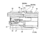
コネクタ1は、図1ないし図6に示すように、前方に開口して角筒状に形成された樹脂製のインナーハウジング16と、インナーハウジング16の内部に収容保持されて、両コネクタ1,2の嵌合時に相手端子12と接続される複数の雌型の接続端子(不図示)と、インナーハウジング16の外周を包囲して嵌合方向に摺動する樹脂製のアウターハウジング17と、インナーハウジング16を相手コネクタ2と嵌合位置で係止するロック機構18と、ロック機構18が半嵌合位置で嵌合操作が解除されたときに、アウターハウジング17に対してインナーハウジング16を反嵌合方向に弾発付勢して押し戻すコイル状のバネ部材19と、インナーハウジング16が反嵌合方向に押し戻される位置を規制する押し戻し規制部20とを備えている。
As shown in FIGS. 1 to 6, the
インナーハウジング16は、角筒状のハウジング本体21と、ハウジング本体21の上部に連設されてハウジング本体21の前端よりも前方に突出する平板状のフード部22とを備えている。ハウジング本体21の内部には、後方から接続端子が挿入されるとともに、前方の開口から相手端子12が挿入される複数の端子収容室23が形成されている。各端子収容室23には、接続端子を係止して抜け止めする可撓性を有したランス24が設けられている(図7)。ハウジング本体21の後方の幅方向の両脇には、バネ部材19の後部を支持する合計4個の第1バネ収容部25が設けられている。
The
ハウジング本体21は、図5に示すように、フード部22が上部に連設された角筒状の基部26と、基部26の前方に設けられて、相手ハウジング11の内周面に対応して形成された角筒状の前部27とを有しており、前部27は、基部26よりも高さ寸法及び幅寸法が小さく設定されている。ハウジング本体21の前部27とフード部22との間には、相手ハウジング11が進入する嵌合スペース28が確保されている。ハウジング本体21の前部27の後方の外周面には、両コネクタ1,2の嵌合時に、相手ハウジング11の内周面との隙間をシールする環状のパッキン29が装着されている。ハウジング本体21の前部27の開口には、接続端子と対応する位置に弾性接触片30を備えたショート端子31が前方から組み付けられ、かつ、各端子収容室23のランス24をロックするためのフロントホルダ32が嵌め込まれる。さらに、ハウジング本体21の基部26の下面には、幅方向の中央部に、押し戻し規制部20を構成する第1爪部33が突設されている。第1爪部33は、前方の基部26の下面に向かって傾斜する前方傾斜面34と、基部26の下面と略直交する後端面35を有している。
As shown in FIG. 5, the housing
フード部22は、図4及び図7に示すように、幅方向の中央部にロック機構18が設けられている。このロック機構18は、フード部22を切り欠いて嵌合方向へ延び、上下に弾性変形可能に形成されたロックアーム36と、ロックアーム36の先端部からフード部の下方へ突出する断面三角形の第1突起37と、ロックアーム36の先端部の幅方向の両側縁からそれぞれフード部の上方へ突出する断面三角形の第2突起38とを含んで構成される。第1突起37は、ハウジング本体21の前部27とフード部22との隙間の嵌合スペース28に進入する相手ハウジング11の係止突起15を係止することで、インナーハウジング16と相手ハウジング11を係止するようになっている。第2突起38は、アウターハウジング17が嵌合方向へ押し出されたときに、アウターハウジング17の前端部の内周面(図7の傾斜面17a)と接触可能に形成されている。フード部22の上面には、幅方向の両側の2箇所に、押し戻し規制部20を構成する第2爪部39が突設されている。第2爪部39は、前方のフード部22の上面に向かって傾斜する前方傾斜面40と、フード部22の上面と略直交する後端面41を有している。フード部22の幅方向の両側縁には、前後方向に亘って垂下する縁部42が設けられ、各縁部42の外方の側面には、アウターハウジング17の内周から突出するリブ43(図2)が係合される溝44が形成されている。フード部22の後端部には、アウターハウジング17の後端面と当接してインナーハウジング16の嵌合方向への離脱を防止するための規制リブ45が設けられている。また、図3に示すように、フード部22の下面には、相手ハウジング11の2本の第1突条部13を案内する1対の案内リブ46が突設されている。
As shown in FIGS. 4 and 7, the
アウターハウジング17は、図3に示すように、角筒状に形成された枠体であり、その後方からインナーハウジング16が組み込まれるようになっている。アウターハウジング17は、内周面から突出するリブ43がインナーハウジングの幅方向の両側の縁部42の溝44に係合することで、インナーハウジング16を嵌合方向に摺動可能に保持するようになっている。アウターハウジング17の内周面は、インナーハウジング16のハウジング本体21の基部26の幅方向の両側面及び下面と摺接するように形成されるとともに、相手ハウジング11の2本の第2突条部14を案内する案内溝47を有している。
As shown in FIG. 3, the
アウターハウジング17は、インナーハウジング16が組み付けられると、図6に示すように、アウターハウジング17の内周面とインナーハウジング16のハウジング本体21の前部27の外周面との間に、相手ハウジングが進入する環状の嵌合スペース48が確保されるようになっている。また、アウターハウジング17の幅方向の両脇には、バネ部材19の前部を支持する合計4個の第2バネ収容部49が設けられている。さらに、図2に示すように、アウターハウジング17の上部の前端中央部には、インナーハウジング16のロックアーム36の上方への弾性変形を許容する切り欠き部50が設けられている。この切り欠き部50の奥側のアウターハウジング17の内周面には、両コネクタ1,2の嵌合時に、ロックアーム36の第2突起38が当接する傾斜面17aが形成されている(図7)。
In the
アウターハウジング17の下部には、図3及び図7に示すように、幅方向の中央部を前後方向に切り欠いて前方(嵌合方向)の内側へ延び、上下に弾性変形可能に形成されたアーム片51と、アーム片51よりも後方の内面から突出する凸部52とが設けられている。アーム片51は、相手ハウジング11に当接する前端面が嵌合スペース48に配置され、かつ、前後方向を長手とする矩形の第1穴部53が設けられている。凸部52は、アウターハウジング17に組み付けられたインナーハウジング16のハウジング本体21の基部26の下面に摺接可能に形成され、インナーハウジング16と摺接するアウターハウジング17の摺動面の一部となっている。第1穴部53は、アウターハウジング17に組み付けられたインナーハウジング16が嵌合方向に摺動する際に、インナーハウジング16のハウジング本体21の下面に突設する第1爪部33が穴内を移動可能に形成され、インナーハウジング16が反嵌合方向へ移動したときに、第1爪部33の後端面35が当接する第1段部54を有している。第1段部54は、インナーハウジング16が反嵌合方向の設定位置まで後退したときに、第1爪部33の後端面35が当接可能な位置に設けられている。以上より、押し戻し規制部20aは、第1爪部33と第1段部54から構成される。
At the lower part of the
アウターハウジング17の上部には、図2及び図8に示すように、幅方向の両側にそれぞれ前後方向を長手とする1対の矩形の第2穴部55が設けられている。1対の第2穴部55は、アウターハウジング17に組み付けられたインナーハウジング16が嵌合方向に摺動する際に、インナーハウジング16の対応する第2爪部39がそれぞれ穴内を移動可能に形成され、インナーハウジング16が反嵌合方向へ移動したときに、第2爪部39の後端面41がそれぞれ当接する第2段部56を有している。第2段部56は、インナーハウジング16が反嵌合方向の設定位置まで後退したときに、第2爪部39の後端面41がそれぞれ当接可能な位置に設けられている。以上より、押し戻し規制部20bは、第2爪部39と第2段部56から構成される。
As shown in FIG. 2 and FIG. 8, a pair of rectangular
このように、本実施形態では、図2及び図3に示すように、第1爪部33と第1段部54を含む押し戻し規制部20aと、第2爪部39と第2段部56を含む押し戻し規制部20bとを備えている。そのため、両コネクタの嵌合操作が半嵌合状態で解除され、後述するように、インナーハウジング16がバネ部材19の弾発付勢力によって反嵌合方向に押し戻されると、第1爪部33が第1段部54に当接され、かつ第2爪部39が第2段部56に当接されることで、インナーハウジング16の半嵌合方向への移動が規制され、アウターハウジング17に対するインナーハウジング16の離脱が防止される。なお、第1段部54と第2段部56は、矩形の穴部の側壁をなしているが、各段部を形成する穴の形状は、特に限定されるものではない。
As described above, in the present embodiment, as shown in FIGS. 2 and 3, the
上述したコネクタ1の組立て手順としては、電線が接続された接続端子が、インナーハウジング16の端子収容室23に後方から挿入されてランス24に係止され、パッキン29とフロントホルダ32が、インナーハウジング16に前方から嵌め込まれる。続いて、インナーハウジング16の第1バネ収容部25にバネ部材19の後端部が装着され、アウターハウジング17の第2バネ収容部49にバネ部材19の前端部が装着された状態で、インナーハウジング16が、アウターハウジング17の後方からバネ部材19を圧縮させながらアウタハウジング17に組み込まれる。そして、アウターハウジング17の第1段部54、第2段部56にそれぞれインナーハウジング16の第1爪部33、第2爪部39を係止させると、コネクタ1の組み付けが完了する。
As an assembly procedure of the
次に、このようにして組み付けられたコネクタ1を相手コネクタ2に嵌合接続させるには、まず、コネクタ1のアウターハウジング17を相手ハウジング11に被せるようにして、インナーハウジング16を相手ハウジング11に押し付ける。すると、インナーハウジング16とアウターハウジング17との間の嵌合スペース48に相手ハウジング11の前部が嵌入されるとともに、相手ハウジング11の前部にアーム片51の前端部が押し付けられたアウターハウジング17が、バネ部材19を圧縮させながら後退する。このとき、インナーハウジング16の前部27とフード部22との間の嵌合スペース28に進入した相手ハウジング11の係止突起15は、インナーハウジング16のロック機構18であるロックアーム36の下向きの第1突起37を押し付けて、ロックアーム36を上方へ撓ませることにより、第1突起37に係止される。これにより、ロックアーム36の上方への撓みが解消され、バネ部材19に弾発付勢されたアウターハウジング17が嵌合方向へ押し出されるとともにバネ部材19の付勢力が開放されて、両コネクタ1,2が完全嵌合に至り、嵌合接続が完了する。また、アウターハウジング17が嵌合方向へ押し出されると、ロックアーム36の上向きの第2突起38にアウターハウジング17の切り欠き部50の傾斜面17aが当接されて、ロックアーム36の上方への撓みが規制されるので、両コネクタ1,2の嵌合状態が保持される。
Next, in order to fit and connect the
一方、両コネクタ1,2が完全嵌合に至る前の半嵌合状態、つまりロック機構18が半嵌合位置の状態で、インナーハウジング16から手が離れると、バネ部材19に弾発付勢されたアウターハウジング17が相手コネクタ2を押し戻しつつ、インナーハウジング16が反嵌合方向に押し戻される。これにより、両コネクタ1,2が離間され、嵌合操作が強制的に解除されるので、コネクタ1の半嵌合を検知することができる。
On the other hand, when the hand is released from the
ところで、本実施形態のコネクタ1のように複数の接続端子を収容する多極のコネクタでは、相手コネクタ2との接続時(嵌合時)の摺動摩擦が大きくなることから、半嵌合を検知するために、バネ部材19の弾発力(バネ定数)を大きく設定する必要がある。しかし、バネ部材19の弾発力が大きすぎると、半嵌合時に押し戻し規制部20の各爪部33,39が対応する段部54,56に当接したときに押し戻し規制部20に作用する衝撃力が大きくなり、押し戻し規制部20に不具合が生じるおそれがある。
By the way, in the multipolar connector which accommodates a plurality of connection terminals like the
この点、本実施形態のコネクタ1は、インナーハウジング16とアウターハウジング17の互いに摺接する摺動面に対し、各爪部33,39が対応する段部54,56に当接する前に、両摺動面が協働して摺動摩擦が大きくなる摺動負荷部60を設けている。具体的に、本実施形態の摺動負荷部60は、インナーハウジング16の第1爪部33と第2爪部39に対応する位置にそれぞれ摺動負荷部60a,60bを設けている。
In this respect, the
摺動負荷部60aは、図7に示すように、インナーハウジング16のハウジング本体21の基部26の下面(一方の摺動面)の第1爪部33が形成される位置よりも第1段部54側(反嵌合方向)の手前に設けられ、第1爪部33に近づくほど、基部26の下面からの膨らみ(高さ)が大きくなる第1傾斜面61を有している。この第1傾斜面61には、アウターハウジング17の対応する内周の摺動面である凸部52が摺接可能になっている。
As shown in FIG. 7, the sliding
また、摺動負荷部60bは、図8に示すように、インナーハウジング16のフード部22の上面(一方の摺動面)の各第2爪部39が形成される位置よりも第2段部56側(反嵌合方向)の手前に設けられ、それぞれ、第2爪部39に近づくほど、フード部22の上面からの膨らみ(高さ)が大きくなる第2傾斜面62を有している。この第2傾斜面62には、アウターハウジング17の対応する内周の摺動面が摺接可能になっている。
Further, as shown in FIG. 8, the sliding
第1傾斜面61は、第1穴部53に収容される幅寸法(例えば、第1爪部33と同じ幅寸法)を有しており、その傾斜面の上端が第1爪部33の後端面35に連なって形成されている。第2傾斜面62は、第2穴部55に収容される幅寸法(例えば、第2爪部39と同じ幅寸法)を有しており、傾斜面の上端が第2爪部39の後端面41に連なって形成されている。なお、各傾斜面61,62は、それぞれ爪部33,39と離れて設けることもできる。
The first
本実施形態では、アウターハウジング17の内周の摺動面と摺接するインナーハウジング16の外周の摺動面に、第1爪部33の位置よりも第1段部54側に摺動負荷部60aである傾斜面61を設けるとともに、各第2爪部39の位置よりも第2段部56側に摺動負荷部60bである傾斜面62を設けているので、ロック機構18が半嵌合位置でインナーハウジング16から手が離れる等、嵌合操作が途中で解除され、バネ部材19の弾発力によってインナーハウジング16が反嵌合方向に押し戻されると、各爪部33,39が対応する段部54,56と当接する前に、アウターハウジング17の対応する摺動面が各傾斜面61,62を乗り上げる(図9、図10)。これにより、各爪部33,39が対応する段部54,56と当接する前に、両ハウジング16,17の摺動面間の摺動摩擦を増加させることができるから、インナーハウジング16が反嵌合方向に押し戻される速度を減少させることができ、その結果、押し戻し規制部20の各爪部33,39が対応する段部54,56と当接したときに押し戻し規制部20に作用する衝撃力を小さくすることができる。このように、摺動負荷部60a,60bでは、押し戻し規制部20に作用する衝撃力を消費するようになっている。したがって、バネ部材19の弾発力を大きくしても、押し戻し規制部20における不具合(損傷等)の発生を防ぐことができる。
In the present embodiment, on the sliding surface of the outer periphery of the
また、本実施形態では、第1爪部33と第1傾斜面61、及び、第2爪部39と第2傾斜面62がそれぞれ一体形成されるから、インナーハウジング16の形状が簡単になる。そのため、インナーハウジング16を成形する金型の構造を単純化することができ、製造コストを低く抑えることができる。
Further, in the present embodiment, since the
また、本実施形態では、第1爪部33と第2爪部39をそれぞれインナーハウジング16に形成し、第1段部54を有する第1穴部53と第2段部56を有する第2穴部55をそれぞれアウターハウジング17に形成する例を説明したが、この構成に限られるものではなく、例えば、第1爪部33と第2爪部39をそれぞれアウターハウジング17に形成し、第1段部54を有する第1穴部53と第2段部56を有する第2穴部55をそれぞれインナーハウジング16に形成することもできる。この場合、摺動負荷部60a,60bは、アウターハウジング17の各爪部33,39の段部54,56側である嵌合方向の手前に各傾斜面61,62を設けることになる。
Further, in the present embodiment, the
なお、本実施形態の第1傾斜面61と第2傾斜面62は、各傾斜面の傾斜角度や最大高さ等を適宜設定することで、両ハウジング16,17の互いに摺接する摺動面間の摺動摩擦を所望の大きさに調整することができる。したがって、バネ部材19の弾発力に応じて、第1傾斜面61と第2傾斜面62の形状や寸法を設定することで、押し戻し規制部20における不具合の発生を確実に防止することができる。
Note that the first
以下では、第1の実施形態と異なる摺動負荷部を備えたコネクタの他の実施形態について説明する。ただ、これらの各実施形態はいずれも基本的には第1の実施形態のそれと同様である。したがって以下では、各実施形態に特徴的な構成となる摺動負荷部についてだけ説明し、第1の実施形態と共通する構成については同一の符号を付して説明を省略する。 Below, other embodiment of the connector provided with the sliding load part different from 1st Embodiment is described. However, each of these embodiments is basically the same as that of the first embodiment. Therefore, in the following, only the sliding load portion which is a characteristic configuration of each embodiment will be described, and the configuration common to the first embodiment is denoted by the same reference numeral and the description will be omitted.
(第2の実施形態)
本実施形態では、インナーハウジング16とアウターハウジング17の互いに摺接する摺動面に対し、各爪部33,39が対応する段部54,56に当接する前に、両摺動面が協働して摺動摩擦が大きくなる摺動負荷部70a,70bを設けている。
Second Embodiment
In the present embodiment, with respect to the sliding surfaces of the
摺動負荷部70aは、図11に示すように、インナーハウジング16のハウジング本体21の基部26の下面(一方の摺動面)の第1爪部33が形成される位置よりも第1段部54側に設けられた第1の凸部71と、第1の凸部71を乗り越え可能にアウターハウジング17の対応する内周の摺動面(相手方の摺動面)に設けられた第2の凸部72とから構成されている。第2の凸部72は、第1の凸部71を乗り越えた後、ハウジング本体21の基部26の下面で、第1爪部33の後端面35と第1の凸部71の間の平面部と摺接するようになっている。なお、第1の凸部71と第2の凸部72は、断面台形状の略同寸に設定されているが、断面形状はこれに限られるものではなく、例えば、断面円弧状とすることもできる。
As shown in FIG. 11, the sliding
摺動負荷部70bは、図12及び図13に示すように、インナーハウジング16のフード部22の上面(一方の摺動面)の各第2爪部39が形成される位置よりも第2段部56側にそれぞれ設けられた第3の凸部73と、各第3の凸部73を乗り越え可能にアウターハウジング17の対応する内周の摺動面(相手方の摺動面)にそれぞれ設けられた第4の凸部74とから構成されている。第4の凸部74は、第3の凸部73を乗り越えた後、インナーハウジング16のフード部22の上面で、第2爪部39の後端面41と第3の凸部73の間の平面部と摺接するようになっている。なお、第3の凸部73と第4の凸部74は、断面台形状の略同寸に設定されているが、断面形状はこれに限られるものではなく、例えば、断面円弧状とすることもできる。
As shown in FIGS. 12 and 13, the sliding
本実施形態では、インナーハウジング16の摺動面の第1爪部33が形成された位置よりも第1段部54側に設けられた第1の凸部71と、第1の凸部71を乗り越え可能にアウターハウジング17の対応する摺動面に設けられた第2の凸部72とから構成される摺動負荷部70aと、インナーハウジング16の摺動面の各第2爪部39が形成された位置よりも第2段部56側にそれぞれ設けられた第3の凸部73と、各第3の凸部73を乗り越え可能にアウターハウジング17の対応する摺動面にそれぞれ設けられた第4の凸部74とから構成される摺動負荷部70bとを設けている。そのため、ロック機構18が半嵌合位置でインナーハウジング16から手が離れる等、嵌合操作が途中で解除され、バネ部材19の弾発力によってインナーハウジング16が反嵌合方向に押し戻された場合、各爪部33,39が対応する段部54,56と当接する前に、第2の凸部72が第1の凸部71を乗り越えるとともに、第4の凸部74が第3の凸部73を乗り越える。これにより、各爪部33,39が対応する段部54,56と当接する前に、両ハウジング16,17の摺動面間の摺動摩擦を増加させることができるから、インナーハウジング16が反嵌合方向に押し戻される速度を減少させることができ、その結果、押し戻し規制部20の各爪部33,39が対応する段部54,56と当接したときに押し戻し規制部20に作用する衝撃力を小さくすることができる。したがって、バネ部材19の弾発力を大きくしても、押し戻し規制部20における不具合(損傷等)の発生を防ぐことができる。
In the present embodiment, the first
また、本実施形態では、第1爪部33と第2爪部39をそれぞれインナーハウジング16に形成し、第1段部54を有する第1穴部53と第2段部56を有する第2穴部55をそれぞれアウターハウジング17の摺動面に形成する例を説明したが、この構成に限られるものではなく、例えば、第1爪部33と第2爪部39をそれぞれアウターハウジング17の摺動面に形成し、第1段部54を有する第1穴部53と第2段部56を有する第2穴部55をそれぞれインナーハウジング16の摺動面に形成することもできる。この場合、各摺動負荷部70a,70bは、アウターハウジング17の摺動面の各爪部33,39の段部54,56側である嵌合方向の手前に、第1の凸部71、第3の凸部73が設けられ、第1の凸部71、第3の凸部73を乗り越え可能となるように、インナーハウジング16の対応する摺動面に第2の凸部72、第4の凸部74が設けられることになる。
Further, in the present embodiment, the
なお、本実施形態の第1〜第4の凸部71,72,73,74は、断面形状や突出高さを適宜設定することで、両ハウジング16,17の互いに摺接する摺動面間の摺動摩擦を所望の大きさに調整することができる。したがって、バネ部材19の弾発力に応じて、第1〜第4の凸部71,72,73,74の断面形状や突出高さを設定することで、押し戻し規制部20における不具合の発生を確実に防止することができる。
The first to fourth
(第3の実施形態)
本実施形態では、インナーハウジング16とアウターハウジング17の互いに摺接する摺動面に対し、1対の第2爪部39が対応する第2段部56に当接する前に、両摺動面が協働して摺動摩擦が大きくなる摺動負荷部80を設けている。
Third Embodiment
In the present embodiment, before the pair of
摺動負荷部80は、図14ないし図16に示すように、アウターハウジング17の摺動面の一部を切り欠いてインナーハウジング16のフード部22の上面(相手方の摺動面)に向けて弾性変形可能に突設された1対のアーム部81と、1対のアーム部81の先端が摺接するインナーハウジング16のフード部22の上面に設けられた1対の凸部82とから構成されている。
As shown in FIGS. 14 to 16, the sliding load portion 80 cuts a part of the sliding surface of the
1対の凸部82は、図15に示すように、それぞれ第2爪部39に対して嵌合方向と直交する方向にずらした位置(1対の第2爪部39間の内側)に設けられている。また、1対の凸部82は、第2爪部39よりも嵌合方向にずらして設けられ、1対の第2爪部39が対応する第2段部56に当接する前に、アーム部81の先端が摺接する位置に設けられている。各凸部82は、いずれも断面円弧状の略同寸に設定されているが、断面形状はこれに限られるものではなく、例えば、断面台形状とすることもできる。
As shown in FIG. 15, the pair of
1対のアーム部は、図16に示すように、アウターハウジング17の周囲を前後方向に切り欠いて後方(半嵌合方向)の内側へ延びている。各アーム部81の先端の下部には、凸部82と摺接する傾斜面81aが設けられている。
As shown in FIG. 16, the pair of arm portions is notched in the front-rear direction around the
本実施形態では、アウターハウジング17の内周の摺動面からインナーハウジング16の外周の摺動面に向けて弾性変形可能に突設されたアーム部81と、アーム部81の先端が摺接するインナーハウジング16の摺動面から突出する凸部82とから構成された摺動負荷部80を設けているので、ロック機構18が半嵌合位置でインナーハウジング16から手が離れる等、嵌合操作が解除され、バネ部材19の弾発力によってインナーハウジング16が反嵌合方向に押し戻された場合、各爪部33,39が対応する段部54,56と当接する前に、1対のアーム部81の先端の傾斜面81aがそれぞれ凸部82と摺接する。これにより、各爪部33,39が対応する段部54,56と当接する前に、両ハウジング16,17の摺動面間の摺動摩擦を増加させることができるから、インナーハウジング16が反嵌合方向に押し戻される速度を減少させることができ、その結果、押し戻し規制部20の各爪部33,39が対応する段部54,56と当接したときに押し戻し規制部20に作用する衝撃力を小さくすることができる。したがって、バネ部材19の弾発力を大きくしても、押し戻し規制部20における不具合(損傷等)の発生を防ぐことができる。
In the present embodiment, an inner portion of the
また、本実施形態では、1対のアーム部81をアウターハウジング17の摺動面に形成し、1対の凸部82をインナーハウジング16の摺動面に形成する例を説明したが、この構成に限られるものではなく、例えば、1対のアーム部81をインナーハウジング16の摺動面に形成し、1対の凸部82をアウターハウジング17の摺動面に形成することもできる。また、本実施形態では、1対の凸部82を1対の第2爪部39間の内側に設ける例を説明したが、1対の凸部82とアーム部81は、各爪部33,39が対応する段部54,56と当接する前に、アーム部81の先端が凸部82と摺接するように設定されていれば、これらの設置位置や設置数は、本実施形態の例に限定されるものではない。例えば、本実施形態の例に加えて、インナーハウジング16のハウジング本体21の基部26の下面に他の凸部82を設けるとともに、アウターハウジング17の対応する摺動面に他のアーム部81を設けることもできる。このように、本実施形態によれば、押し戻し規制部20の位置に関係なく、摺動負荷部80を所定の位置に設けることができるから、摺動負荷部80の設計自由度を格段に高めることができる。
Further, in the present embodiment, an example in which the pair of
なお、本実施形態の凸部82は、断面形状や突出高さを適宜設定することで、両ハウジング16,17の互いに摺接する摺動面間の摺動摩擦を所望の大きさに調整することができる。したがって、バネ部材19の弾発力に応じて、凸部82の断面形状や突出高さを設定することで、押し戻し規制部20における不具合の発生を確実に防止することができる。
In addition, the
1 コネクタ
2 相手コネクタ
16 インナーハウジング
17 アウターハウジング
18 ロック機構
19 バネ部材
20 押し戻し規制部
33 第1爪部
39 第2爪部
54 第1段部
56 第2段部
60 摺動負荷部
61 第1傾斜面
62 第2傾斜面
70 摺動負荷部
71 第1の凸部
72 第2の凸部
73 第3の凸部
74 第4の凸部
80 摺動負荷部
81 アーム部
82 凸部
DESCRIPTION OF
Claims (2)
前記押し戻し規制部は、前記両ハウジングの互いに摺接する摺動面の一方の前記摺動面から突出して設けられた爪部と、前記インナーハウジングが押し戻された設定位置で前記爪部が当接可能に相手方の前記摺動面に設けられた段部とを有し、
前記両ハウジングの摺動面は、前記爪部が前記段部と当接する前に、前記両摺動面が協働して摺動摩擦が大きくなる摺動負荷部を設けてなり、
前記摺動負荷部は、前記一方の摺動面の前記爪部が形成された位置よりも前記段部側に設けられた第1の凸部と、前記第1の凸部を乗り越え可能に前記相手方の摺動面に設けられた第2の凸部とを有してなることを特徴とするコネクタ。 A cylindrical inner housing holding the connection terminals inside, a cylindrical outer housing that slides around the outer periphery of the inner housing and sliding in the fitting direction, and the inner housing is locked at the mating position with the mating connector A locking mechanism, a spring member resiliently urging the inner housing against the outer housing in the reverse fitting direction, and pushing back when the fitting operation is released at the half fitting position of the lock mechanism; And a push-back restricting portion that restricts a position at which the inner housing is pushed back in the anti-fitting direction,
The push-back restricting portion can contact the claw portion provided at a setting position where the inner housing is pushed back, with the claw portion provided protruding from one of the sliding surfaces of the sliding surfaces of the two housings slidingly contacting each other. And a stepped portion provided on the sliding surface of the other,
The sliding surfaces of the two housings are provided with a sliding load portion where the sliding surfaces cooperate with each other to increase the sliding friction before the claws abut on the steps.
The sliding load portion is capable of moving over the first convex portion provided on the step side with respect to the position where the claw portion of the one sliding surface is formed and the first convex portion. the second characterized by having the convex portion of the to Turkey connector provided on the sliding surface of the other party.
前記押し戻し規制部は、前記両ハウジングの互いに摺接する摺動面の一方の前記摺動面から突出して設けられた爪部と、前記インナーハウジングが押し戻された設定位置で前記爪部が当接可能に相手方の前記摺動面に設けられた段部とを有し、
前記両ハウジングの摺動面は、前記爪部が前記段部と当接する前に、前記両摺動面が協働して摺動摩擦が大きくなる摺動負荷部を設けてなり、
前記摺動負荷部は、前記両ハウジングの互いに摺接する摺動面の一部を切り欠いて相手方の前記摺動面に向けて弾性変形可能に突設されたアーム部と、該アーム部の先端が摺接する前記相手方の摺動面に設けられた凸部とを有してなることを特徴とするコネクタ。
A cylindrical inner housing holding the connection terminals inside, a cylindrical outer housing that slides around the outer periphery of the inner housing and sliding in the fitting direction, and the inner housing is locked at the mating position with the mating connector A locking mechanism, a spring member resiliently urging the inner housing against the outer housing in the reverse fitting direction, and pushing back when the fitting operation is released at the half fitting position of the lock mechanism; And a push-back restricting portion that restricts a position at which the inner housing is pushed back in the anti-fitting direction,
The push-back restricting portion can contact the claw portion provided at a setting position where the inner housing is pushed back, with the claw portion provided protruding from one of the sliding surfaces of the sliding surfaces of the two housings slidingly contacting each other. And a stepped portion provided on the sliding surface of the other,
The sliding surfaces of the two housings are provided with a sliding load portion where the sliding surfaces cooperate with each other to increase the sliding friction before the claws abut on the steps.
The sliding load portion is formed by cutting out a part of sliding surfaces of the two housings in sliding contact with each other, and projecting an arm portion so as to elastically deform toward the other sliding surface, and a tip of the arm portion There features and to Turkey connectors to become and a protrusion provided on the sliding surface of the counterpart in sliding contact.
Priority Applications (5)
| Application Number | Priority Date | Filing Date | Title |
|---|---|---|---|
| JP2016236633A JP6550034B2 (en) | 2016-12-06 | 2016-12-06 | connector |
| EP17878971.5A EP3553896B1 (en) | 2016-12-06 | 2017-10-20 | Connector |
| CN201780068565.5A CN109923741B (en) | 2016-12-06 | 2017-10-20 | Connector with a locking member |
| PCT/JP2017/038050 WO2018105251A1 (en) | 2016-12-06 | 2017-10-20 | Connector |
| US16/402,189 US10559924B2 (en) | 2016-12-06 | 2019-05-02 | Connector |
Applications Claiming Priority (1)
| Application Number | Priority Date | Filing Date | Title |
|---|---|---|---|
| JP2016236633A JP6550034B2 (en) | 2016-12-06 | 2016-12-06 | connector |
Publications (2)
| Publication Number | Publication Date |
|---|---|
| JP2018092832A JP2018092832A (en) | 2018-06-14 |
| JP6550034B2 true JP6550034B2 (en) | 2019-07-24 |
Family
ID=62491926
Family Applications (1)
| Application Number | Title | Priority Date | Filing Date |
|---|---|---|---|
| JP2016236633A Active JP6550034B2 (en) | 2016-12-06 | 2016-12-06 | connector |
Country Status (5)
| Country | Link |
|---|---|
| US (1) | US10559924B2 (en) |
| EP (1) | EP3553896B1 (en) |
| JP (1) | JP6550034B2 (en) |
| CN (1) | CN109923741B (en) |
| WO (1) | WO2018105251A1 (en) |
Families Citing this family (1)
| Publication number | Priority date | Publication date | Assignee | Title |
|---|---|---|---|---|
| GB201801457D0 (en) * | 2018-01-30 | 2018-03-14 | Pragmatic Printing Ltd | Integrated circuit manufacturing process and apparatus |
Family Cites Families (6)
| Publication number | Priority date | Publication date | Assignee | Title |
|---|---|---|---|---|
| JP3404966B2 (en) * | 1995-03-06 | 2003-05-12 | 富士通株式会社 | Plug-in rail |
| JP3047159B2 (en) * | 1995-11-09 | 2000-05-29 | 矢崎総業株式会社 | Connector mating structure |
| JPH11224728A (en) | 1998-02-04 | 1999-08-17 | Yazaki Corp | Half-fitting preventive connector |
| JP3047175B2 (en) * | 1998-03-18 | 2000-05-29 | 矢崎総業株式会社 | Connector mating structure |
| JP3741348B2 (en) * | 1999-06-11 | 2006-02-01 | 矢崎総業株式会社 | Half-mating prevention connector |
| DE10136862C1 (en) | 2001-07-28 | 2003-06-26 | Yazaki Europe Ltd | Plug for connecting to a socket |
-
2016
- 2016-12-06 JP JP2016236633A patent/JP6550034B2/en active Active
-
2017
- 2017-10-20 WO PCT/JP2017/038050 patent/WO2018105251A1/en unknown
- 2017-10-20 CN CN201780068565.5A patent/CN109923741B/en active Active
- 2017-10-20 EP EP17878971.5A patent/EP3553896B1/en active Active
-
2019
- 2019-05-02 US US16/402,189 patent/US10559924B2/en active Active
Also Published As
| Publication number | Publication date |
|---|---|
| CN109923741A (en) | 2019-06-21 |
| EP3553896B1 (en) | 2021-02-17 |
| EP3553896A1 (en) | 2019-10-16 |
| US10559924B2 (en) | 2020-02-11 |
| JP2018092832A (en) | 2018-06-14 |
| WO2018105251A1 (en) | 2018-06-14 |
| US20190260163A1 (en) | 2019-08-22 |
| CN109923741B (en) | 2020-08-07 |
| EP3553896A4 (en) | 2019-12-11 |
Similar Documents
| Publication | Publication Date | Title |
|---|---|---|
| JP6865725B2 (en) | connector | |
| JP5050820B2 (en) | connector | |
| US9431777B2 (en) | Connector | |
| JP5614369B2 (en) | Terminal fitting | |
| WO2014181416A1 (en) | Connector | |
| JP6515825B2 (en) | connector | |
| US11189956B2 (en) | Liquid-tight movable connector | |
| JPH0831517A (en) | Connector fitting detection structure | |
| JP4548272B2 (en) | connector | |
| JP5510346B2 (en) | connector | |
| CN110622367B (en) | Connector with a locking member | |
| JP2006086090A (en) | Connector | |
| JP2016091819A (en) | connector | |
| JP6550034B2 (en) | connector | |
| JP4613747B2 (en) | connector | |
| CN110875553B (en) | Connector with a locking member | |
| JP6119671B2 (en) | connector | |
| JP2005197167A (en) | Connector | |
| JP2020198256A (en) | housing | |
| JP2021005517A (en) | connector | |
| JP5397124B2 (en) | connector | |
| CN107453073B (en) | Box terminal with insertion limiter | |
| JP6265383B2 (en) | Connector structure | |
| JP7103913B2 (en) | Connector mating structure | |
| JP7575437B2 (en) | connector |
Legal Events
| Date | Code | Title | Description |
|---|---|---|---|
| A131 | Notification of reasons for refusal |
Free format text: JAPANESE INTERMEDIATE CODE: A131 Effective date: 20190108 |
|
| A521 | Request for written amendment filed |
Free format text: JAPANESE INTERMEDIATE CODE: A523 Effective date: 20190221 |
|
| TRDD | Decision of grant or rejection written | ||
| A01 | Written decision to grant a patent or to grant a registration (utility model) |
Free format text: JAPANESE INTERMEDIATE CODE: A01 Effective date: 20190604 |
|
| A61 | First payment of annual fees (during grant procedure) |
Free format text: JAPANESE INTERMEDIATE CODE: A61 Effective date: 20190628 |
|
| R150 | Certificate of patent or registration of utility model |
Ref document number: 6550034 Country of ref document: JP Free format text: JAPANESE INTERMEDIATE CODE: R150 |
|
| R250 | Receipt of annual fees |
Free format text: JAPANESE INTERMEDIATE CODE: R250 |
|
| S531 | Written request for registration of change of domicile |
Free format text: JAPANESE INTERMEDIATE CODE: R313531 |
|
| R350 | Written notification of registration of transfer |
Free format text: JAPANESE INTERMEDIATE CODE: R350 |
|
| R250 | Receipt of annual fees |
Free format text: JAPANESE INTERMEDIATE CODE: R250 |