JP6549235B2 - Air flow meter - Google Patents
Air flow meter Download PDFInfo
- Publication number
- JP6549235B2 JP6549235B2 JP2017537655A JP2017537655A JP6549235B2 JP 6549235 B2 JP6549235 B2 JP 6549235B2 JP 2017537655 A JP2017537655 A JP 2017537655A JP 2017537655 A JP2017537655 A JP 2017537655A JP 6549235 B2 JP6549235 B2 JP 6549235B2
- Authority
- JP
- Japan
- Prior art keywords
- temperature
- characteristic
- correction
- flow meter
- air flow
- Prior art date
- Legal status (The legal status is an assumption and is not a legal conclusion. Google has not performed a legal analysis and makes no representation as to the accuracy of the status listed.)
- Active
Links
- 238000012937 correction Methods 0.000 claims description 70
- 230000008859 change Effects 0.000 claims description 10
- 238000010586 diagram Methods 0.000 description 11
- 230000006870 function Effects 0.000 description 6
- 230000008901 benefit Effects 0.000 description 3
- 230000006866 deterioration Effects 0.000 description 3
- 238000000034 method Methods 0.000 description 3
- 238000004891 communication Methods 0.000 description 2
- 238000001514 detection method Methods 0.000 description 2
- 238000012545 processing Methods 0.000 description 2
- 238000013459 approach Methods 0.000 description 1
- 238000009529 body temperature measurement Methods 0.000 description 1
- 238000002485 combustion reaction Methods 0.000 description 1
- 238000010438 heat treatment Methods 0.000 description 1
- 238000012986 modification Methods 0.000 description 1
- 230000004048 modification Effects 0.000 description 1
- 230000004044 response Effects 0.000 description 1
Images


Classifications
-
- G—PHYSICS
- G01—MEASURING; TESTING
- G01F—MEASURING VOLUME, VOLUME FLOW, MASS FLOW OR LIQUID LEVEL; METERING BY VOLUME
- G01F1/00—Measuring the volume flow or mass flow of fluid or fluent solid material wherein the fluid passes through a meter in a continuous flow
- G01F1/68—Measuring the volume flow or mass flow of fluid or fluent solid material wherein the fluid passes through a meter in a continuous flow by using thermal effects
- G01F1/696—Circuits therefor, e.g. constant-current flow meters
-
- G—PHYSICS
- G01—MEASURING; TESTING
- G01F—MEASURING VOLUME, VOLUME FLOW, MASS FLOW OR LIQUID LEVEL; METERING BY VOLUME
- G01F1/00—Measuring the volume flow or mass flow of fluid or fluent solid material wherein the fluid passes through a meter in a continuous flow
-
- G—PHYSICS
- G01—MEASURING; TESTING
- G01F—MEASURING VOLUME, VOLUME FLOW, MASS FLOW OR LIQUID LEVEL; METERING BY VOLUME
- G01F1/00—Measuring the volume flow or mass flow of fluid or fluent solid material wherein the fluid passes through a meter in a continuous flow
- G01F1/68—Measuring the volume flow or mass flow of fluid or fluent solid material wherein the fluid passes through a meter in a continuous flow by using thermal effects
- G01F1/684—Structural arrangements; Mounting of elements, e.g. in relation to fluid flow
- G01F1/6842—Structural arrangements; Mounting of elements, e.g. in relation to fluid flow with means for influencing the fluid flow
-
- G—PHYSICS
- G01—MEASURING; TESTING
- G01F—MEASURING VOLUME, VOLUME FLOW, MASS FLOW OR LIQUID LEVEL; METERING BY VOLUME
- G01F1/00—Measuring the volume flow or mass flow of fluid or fluent solid material wherein the fluid passes through a meter in a continuous flow
- G01F1/68—Measuring the volume flow or mass flow of fluid or fluent solid material wherein the fluid passes through a meter in a continuous flow by using thermal effects
- G01F1/684—Structural arrangements; Mounting of elements, e.g. in relation to fluid flow
- G01F1/6847—Structural arrangements; Mounting of elements, e.g. in relation to fluid flow where sensing or heating elements are not disturbing the fluid flow, e.g. elements mounted outside the flow duct
-
- G—PHYSICS
- G01—MEASURING; TESTING
- G01F—MEASURING VOLUME, VOLUME FLOW, MASS FLOW OR LIQUID LEVEL; METERING BY VOLUME
- G01F1/00—Measuring the volume flow or mass flow of fluid or fluent solid material wherein the fluid passes through a meter in a continuous flow
- G01F1/68—Measuring the volume flow or mass flow of fluid or fluent solid material wherein the fluid passes through a meter in a continuous flow by using thermal effects
- G01F1/684—Structural arrangements; Mounting of elements, e.g. in relation to fluid flow
- G01F1/688—Structural arrangements; Mounting of elements, e.g. in relation to fluid flow using a particular type of heating, cooling or sensing element
-
- G—PHYSICS
- G01—MEASURING; TESTING
- G01F—MEASURING VOLUME, VOLUME FLOW, MASS FLOW OR LIQUID LEVEL; METERING BY VOLUME
- G01F1/00—Measuring the volume flow or mass flow of fluid or fluent solid material wherein the fluid passes through a meter in a continuous flow
- G01F1/68—Measuring the volume flow or mass flow of fluid or fluent solid material wherein the fluid passes through a meter in a continuous flow by using thermal effects
- G01F1/696—Circuits therefor, e.g. constant-current flow meters
- G01F1/6965—Circuits therefor, e.g. constant-current flow meters comprising means to store calibration data for flow signal calculation or correction
-
- G—PHYSICS
- G01—MEASURING; TESTING
- G01F—MEASURING VOLUME, VOLUME FLOW, MASS FLOW OR LIQUID LEVEL; METERING BY VOLUME
- G01F1/00—Measuring the volume flow or mass flow of fluid or fluent solid material wherein the fluid passes through a meter in a continuous flow
- G01F1/68—Measuring the volume flow or mass flow of fluid or fluent solid material wherein the fluid passes through a meter in a continuous flow by using thermal effects
- G01F1/696—Circuits therefor, e.g. constant-current flow meters
- G01F1/698—Feedback or rebalancing circuits, e.g. self heated constant temperature flowmeters
-
- G—PHYSICS
- G01—MEASURING; TESTING
- G01F—MEASURING VOLUME, VOLUME FLOW, MASS FLOW OR LIQUID LEVEL; METERING BY VOLUME
- G01F15/00—Details of, or accessories for, apparatus of groups G01F1/00 - G01F13/00 insofar as such details or appliances are not adapted to particular types of such apparatus
- G01F15/02—Compensating or correcting for variations in pressure, density or temperature
- G01F15/04—Compensating or correcting for variations in pressure, density or temperature of gases to be measured
-
- G—PHYSICS
- G01—MEASURING; TESTING
- G01F—MEASURING VOLUME, VOLUME FLOW, MASS FLOW OR LIQUID LEVEL; METERING BY VOLUME
- G01F5/00—Measuring a proportion of the volume flow
Landscapes
- Physics & Mathematics (AREA)
- Fluid Mechanics (AREA)
- General Physics & Mathematics (AREA)
- Measuring Volume Flow (AREA)
- Details Of Flowmeters (AREA)
Description
本発明は、被計測気体の流量を計測する装置に係り、特に、自動車の内燃機関の吸入空気の流量を計測する空気流量計に関する。 The present invention relates to an apparatus for measuring the flow rate of a gas to be measured, and more particularly to an air flow meter for measuring the flow rate of intake air of an internal combustion engine of a car.
自動車用の空気流量計の温度特性補正方法には、特開2010−216906号公報(特許文献1)に記載の技術がある。この公報には、「空気温度及びセンサモジュール温度を出力特性の調整要素として取り入れるようにし、前記空気温度及び前記センサモジュール温度の差分に応じた出力特性の温度補正を行う」という記載がある。 There exists a technique as described in Unexamined-Japanese-Patent No. 2010-216906 (patent document 1) as a temperature characteristic correction method of the air flow meter for motor vehicles. This publication describes that "the air temperature and the sensor module temperature are taken in as an adjustment factor of the output characteristic, and the temperature correction of the output characteristic according to the difference between the air temperature and the sensor module temperature is performed".
特許文献1では、空気温度及びセンサモジュール温度を2つの温度センサでそれぞれ検出し、検出温度の差分に応じた補正を行うことが記載されているが、2つの温度センサの経時劣化度合いの違いによる温度差や温度センサの個々の特性ばらつきによる温度差の影響が想定されていなかった。そのため、2つの温度センサが経時劣化度合いの差や特性ばらつきにより、同じ温度であるにもかかわらず違う温度を出力した場合、空気流量計の出力に誤差を生じさせてしまうことがある。
Although
本発明の目的は、精度の良い空気流量計を提供することにある。 An object of the present invention is to provide an accurate air flow meter.
上記課題を解決するために、代表的な本発明の空気流量計は、出力を補正する演算回路を備えた空気流量計において、 前記演算回路には、前記空気流量計の出力特性の調整要素として空気温度及びセンサモジュール温度を取り入れ、 前記空気温度と前記センサモジュール温度との温度差に応じて出力特性を補正し、かつ、前記空気温度と前記センサモジュール温度との差の絶対値が閾値より小さいときは、補正量を一次特性とした値と比較して補正量を小さくするものである。 In order to solve the above problems, a representative air flow meter according to the present invention is an air flow meter including an arithmetic circuit that corrects an output, wherein the arithmetic circuit is an adjustment element of an output characteristic of the air flow meter. Take in the air temperature and sensor module temperature, correct the output characteristics according to the temperature difference between the air temperature and the sensor module temperature, and the absolute value of the difference between the air temperature and the sensor module temperature is smaller than a threshold At the same time , the correction amount is made smaller than the value having the first order characteristic .
本発明によれば、精度の良い空気流量計を提供することが可能となる。 According to the present invention, it is possible to provide an accurate air flow meter.
以下、本発明の実施例について図面を用いて説明する。 Hereinafter, embodiments of the present invention will be described with reference to the drawings.
図1は、本発明を適用した場合の空気流量計の回路構成である。定温度制御ブリッジ1は、発熱抵抗体4、ブリッジ回路温度測定用測温抵抗体5、吸気温度補償用の測温抵抗体6、固定抵抗体7〜8より構成される。ヒータ制御回路23は、ブリッジ回路温度測定用測温抵抗体5と吸気温度補償用測温抵抗体6の温度差が一定となるように発熱抵抗体4へ流す電流を制御する。
FIG. 1 shows a circuit configuration of an air flowmeter to which the present invention is applied. The constant
定温度制御ブリッジ1の発熱抵抗体4の周囲に、発熱抵抗体4から放出される熱量を検出する温度差ブリッジ2が配置される。温度差ブリッジ2は、測温抵抗体9〜12で構成され、空気流量及び方向を検出することが出来る。
Around the heat generating resistor 4 of the constant
空気温度を測定する吸気温度センサ3は、固定抵抗体13、温度により抵抗値が変化する感温抵抗体14により構成される。 The intake air temperature sensor 3 for measuring the air temperature is composed of a fixed resistor 13 and a temperature sensitive resistor 14 whose resistance value changes with temperature.
温度差ブリッジ2で検出された流量信号は、個々の回路によりばらつきがあるため目標の出力特性になるように調整する必要がある。また吸気温度センサ3の出力も目標の特性に調整する必要がある。
The flow rate signal detected by the
目標出力特性への調整方法としては、2次以上の多項式による調整や、補正マップによる調整が挙げられる。また調整は、外部コンピュータと接続して行うものである。 Examples of the adjustment method to the target output characteristic include adjustment using a polynomial of second degree or higher and adjustment using a correction map. The adjustment is performed by connecting to an external computer.
出力特性調整回路27は、ヒータ制御回路及び演算機能が一体となったLSI回路であり、回路全体を駆動するための発振器(以下OSCと称する)20、定温度制御ブリッジ1を制御するヒータ制御回路23、定温度制御ブリッジ1、温度差ブリッジ2、吸気温度センサ3及び出力特性調整回路27を駆動する電源である定電圧回路15、回路の温度を検出する回路温度センサ19、空気流量信号を変換するA/D変換器16、吸気温度センサ3出力信号を変換するA/D変換器17、回路温度センサ19の出力信号を変換するA/D変換器18、空気流量信号及び吸気温度センサ信号の補正を実施する演算回路(ディジタルシグナルプロセッサ、以下DSPと称す)22、DSP22で演算したデジタル出力値を電圧値へ変換するD/A変換器25、26、周波数へ変換するフリーランニングカウンター(以下FRCと称する)30,31、デジタル出力であるSENT32、出力調整を行うため外部コンピュータと通信を行う通信回路(シリアルコミュニケーションインターフェース、以下SCIと称す)24、出力形態を切り替えるマルチプレクサ(以下MUXと称す)33、34、調整データを書込む記憶回路(例えばEPROM)21、DSP22を制御するプログラムを格納するROM29、DSP22で計算する途中データを一時的に格納するRAM28、電源VCCへ過大なサージが印加された場合に回路を保護する保護回路35を備えている。
The output
図2は、DSP22で実行する出力調整機能を示した回路ブロック図である。
FIG. 2 is a circuit block diagram showing an output adjustment function executed by the
入力信号として温度差ブリッジ2の出力、回路温度センサ19の出力、吸気温度センサ3の出力を出力特性の調整要素として取り込んでいる。調整は、まず回路温度センサ19の出力を直線補正38、吸気温度センサ3の出力を直線補正39において同じ目標値に調整する。この調整値は任意に設定可能で、温度と目標値をリニアな関係に設定することが望ましい。次に温度差ブリッジ2の出力をゼロスパン補正40において、ゼロ点調整およびスパン調整を行う。
As an input signal, the output of the
次に壁温補正36において、回路温度と吸気温度に差がある状態(壁温状態)時の特性補正を実施する。壁温補正36では、補正後の回路温度センサ19の出力(TLSI)と補正後の吸気温度センサ3の出力(TA)の差分(TA−TLSI)に各流量で異なる最適な定数(K1)42を掛け合わせる。さらに、K1にTA−TLSI応じたゲイン(K2)41を掛け合わせ、壁温補正量(ΔY)を求め、温度差ブリッジ2の出力のゼロスパン調整後流量信号(QA)に足し合わせている。壁温補正36で実施している計算式を(1)に示す。
Next, in the
QA1=QA+K1×K2×(TA−TLSI)・・・(1)
最後に、補正後の回路温度センサ19の出力(TLSI)に応じた補正を出力補正マップ37のデータを用いて壁温補正後の流量信号(QA1)を補正し、流量信号を目標値に合わせる。また同時に、補正後の吸気温度センサ3の出力(TA)は、温度信号として出力される。また本補正は、マップによる補正のみでなく、多項式による補正でも対応可能である。多項式による補正のメリットとしては、記憶回路21、ROM29の容量が小さくて済むことであり、容量が小さければチップサイズの縮小が可能となり低コストが出来る。またマップによる補正のメリットとしては、入力に対する補正量の急激な変化に対応可能であり、高精度化が可能となる点である。QA1 = QA + K1 × K2 × (TA−TLSI) (1)
Finally, correction according to the output (TLSI) of the circuit temperature sensor 19 after correction is performed using the data of the
図3は、壁温補正36から出力される補正量ΔYの特性図を示したものである。補正後の回路温度センサ19の出力(TLSI)と補正後の吸気温度センサ3の出力(TA)の差分(TA−TLSI)の絶対値(|TA−TLSI|)が閾値まではΔYがゼロとなり、閾値を境に傾きK1の1次特性となる。
FIG. 3 shows a characteristic diagram of the correction amount ΔY output from the
図4は、ゲイン(K2)41の特性図を示したものである。閾値を境にゼロ(0)と1のステップ応答の特性を示している。この閾値は、任意に設定可能であり、回路温度センサと吸気温度センサの経時劣化度合いや特性ばらつきを考慮して設定するのが望ましい。 FIG. 4 shows a characteristic diagram of the gain (K2) 41. As shown in FIG. The characteristic of the step response of zero (0) and one is shown bordering on the threshold. The threshold value can be set arbitrarily, and is desirably set in consideration of the degree of deterioration with time and the characteristic variation of the circuit temperature sensor and the intake air temperature sensor.
本実施例は、実施例1記載の回路構成において壁温補正36で実施される補正特性の異なるものを対象としたものである。
The present embodiment is directed to one having a different correction characteristic implemented by the
図5は、壁温補正36から出力される補正量ΔYの特性図を示したものである。補正後の回路温度センサ19の出力(TLSI)と補正後の吸気温度センサ3の出力(TA)の差分(TA−TLSI)の絶対値(|TA−TLSI|)が閾値まではΔYがゼロとなり、閾値を境に傾きK1に近づく1次特性となる。
FIG. 5 shows a characteristic diagram of the correction amount ΔY output from the
図6は、ゲイン(K2)41の特性図を示したものである。閾値までがゼロとなり、閾値以降で1次の特性を示している。 FIG. 6 shows a characteristic diagram of the gain (K2) 41. As shown in FIG. The value up to the threshold is zero, and the first-order characteristic is shown after the threshold.
本構成をとることで、閾値前後の不連続点での特性変動を小さくすることができる利点がある。 By taking this configuration, there is an advantage that characteristic fluctuation at discontinuous points around the threshold can be reduced.
本実施例では実施例1記載の回路構成において、壁温補正36で実施される補正特性の異なるもを対象としたものである。
In this embodiment, in the circuit configuration described in the first embodiment, the difference in the correction characteristic implemented by the
図7は、壁温補正36から出力される補正量ΔYの特性図を示したものである。補正後の回路温度センサ19の出力(TLSI)と補正後の吸気温度センサ3の出力(TA)の差分(TA−TLSI)の絶対値(|TA−TLSI|)が閾値までは2次特性となり、閾値を境に1次特性となる。
FIG. 7 shows a characteristic diagram of the correction amount ΔY output from the
図8は、ゲイン(K2)41の特性図を示したものである。閾値までが1次特性となり、閾値を境にK2=1の特性を示している。 FIG. 8 shows a characteristic diagram of the gain (K2) 41. As shown in FIG. The first-order characteristic is up to the threshold value, and the characteristic of K2 = 1 is shown at the threshold value.
本構成をとることで、閾値前後の特性変動を小さくでき、且つ閾値以降は、傾きK1の1次特性とすることができる利点がある。 By adopting this configuration, it is possible to reduce the characteristic fluctuation around the threshold value, and there is an advantage that after the threshold value, the primary characteristic of the slope K1 can be set.
本実施例では、実施例1記載の回路構成において壁温補正36で実施される補正特性の異なるもを対象としたものである。
The present embodiment is directed to the circuit configuration described in the first embodiment which is different in the correction characteristic implemented by the
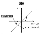
図9は、壁温補正36から出力される補正量ΔYの特性図を示したものである。補正後の回路温度センサ19の出力(TLSI)と補正後の吸気温度センサ3の出力(TA)の差分(TA−TLSI)の絶対値(|TA−TLSI|)が閾値1まではΔYがゼロとなり、閾値1から閾値2までは2次特性となり、閾値2以降では1次特性となる。
FIG. 9 is a characteristic diagram of the correction amount ΔY output from the
図10は、ゲイン(K2)41の特性図を示したものである。閾値1まではゼロとなり、閾値1から閾値2までは1次特性となり、閾値2以降K2=1の特性を示している。
FIG. 10 shows a characteristic diagram of the gain (K2) 41. As shown in FIG. The threshold value is zero until
本構成をとることで、閾値1及び閾値2前後の特性変動を小さくでき、且つ閾値2以降は、傾きK1の1次特性とすることができる利点がある。
By adopting this configuration, it is possible to reduce the characteristic fluctuation around
なお、本発明は上記した実施例に限定されるものではなく、様々な変形例が含まれる。例えば、上記した実施例は本発明を分かりやすく説明するために詳細に説明したものであり、必ずしも説明した全ての構成を備えるものに限定されるものではない。また、ある実施例の構成の一部を他の実施例の構成に置き換えることが可能であり、また、ある実施例の構成に他の実施例の構成を加えることも可能である。また、各実施例の構成の一部について、他の構成の追加・削除・置換をすることが可能である。また、上記の各構成、機能、処理部、処理手段等は、それらの一部又は全部を例えば集積回路で設計する等によりハードウェアで実現してもよい。また、上記の各構成、機能等は、プロセッサがそれぞれの機能を実現するプログラムを解釈し、実行することによりソフトウェアで実現してもよい。各機能を実現するプログラム、マップ、補正値等の情報は、メモリやROM、EPROM、フラッシュメモリ等の記憶装置におくことができる。
The present invention is not limited to the embodiments described above, but includes various modifications. For example, the embodiments described above are described in detail in order to explain the present invention in an easy-to-understand manner, and are not necessarily limited to those having all the configurations described. Also, part of the configuration of one embodiment can be replaced with the configuration of another embodiment, and the configuration of another embodiment can be added to the configuration of one embodiment. In addition, with respect to a part of the configuration of each embodiment, it is possible to add, delete, and replace other configurations. Further, each of the configurations, functions, processing units, processing means, etc. described above may be realized by hardware by designing a part or all of them with, for example, an integrated circuit. Further, each configuration, function, etc. described above may be realized by software by the processor interpreting and executing a program that realizes each function. Information such as a program for realizing each function, a map, and a correction value can be stored in a storage device such as a memory, a ROM, an EPROM, or a flash memory.
1・・・定温度制御ブリッジ、2・・・温度差ブリッジ、3・・・吸気温度センサ、4・・・発熱抵抗体、5〜6・・・測温抵抗体、7〜8、13・・・固定抵抗体、9〜12・・・測温抵抗体、14・・・感温抵抗体、15・・・定電圧回路、16〜18・・・A/D変換器、19・・・回路温度センサ、21・・・記憶回路、22・・・DSP、23・・・ヒータ制御回路、24・・・SCI、25〜26・・・D/A変換器、27・・・出力特性調整回路、28・・・RAM、29・・・ROM、30〜31・・・FRC、32・・・SENT、33〜34・・・MUX、35・・・保護回路、36・・・壁温補正、37・・・出力補正、38〜39・・・直線補正、40・・・ゼロスパン補正
1 · · · · · · · · · · · · · · · · · · · · · · · · · · · · · · · · · · · · · · · · · · · · · · · · · · · · · · · · · · · · · · · · · · · · · · · · · · · · · · · · · · · · · · · · · · · · · · · · · · · · · · · · · · · · · · · · · · · · · · · · · · · · · · · · · · · · · · · · · · · · · · · · Fixed resistor, 9 to 12 · · · Temperature measuring resistor, 14 · · · Temperature sensitive resistor, 15 · · · · · · · · · · · 18 18 A / D converter, 19 · · ·
Claims (6)
前記演算回路には、前記空気流量計の出力特性の調整要素として空気温度及びセンサモジュール温度を取り入れ、
前記空気温度と前記センサモジュール温度との温度差に応じて出力特性を補正し、かつ、前記空気温度と前記センサモジュール温度との差の絶対値が閾値より小さいときは、補正量を一次特性とした値と比較して補正量を小さくすることを特徴とする空気流量計。 In an air flow meter including an arithmetic circuit that corrects the output,
The arithmetic circuit incorporates an air temperature and a sensor module temperature as adjustment elements of the output characteristic of the air flow meter,
The output characteristic is corrected according to the temperature difference between the air temperature and the sensor module temperature, and when the absolute value of the difference between the air temperature and the sensor module temperature is smaller than a threshold , the correction amount is set to the primary characteristic An air flow meter characterized in that the amount of correction is reduced compared to the value of
前記出力特性の補正量は、変化率が異なる第一の領域と第二の領域を有することを特徴とする空気流量計。 In the air flow meter according to claim 1,
The air flowmeter according to claim 1, wherein the correction amount of the output characteristic includes a first area and a second area having different change rates.
前記第一の領域は、前記第二の領域の変化率より小さい変化率であることを特徴とする空気流量計。 In the air flow meter according to claim 2,
An air flow meter characterized in that the first area has a change rate smaller than the change rate of the second area.
前記第一の領域は、前記空気温度と前記センサモジュール温度との温度差に対する補正量の変化率がゼロであり、
前記第二の領域の変化率は、1次特性を有していることを特徴とする空気流量計。 In the air flow meter according to claim 2 or 3,
In the first area, the rate of change of the correction amount with respect to the temperature difference between the air temperature and the sensor module temperature is zero.
An air flow meter characterized in that the rate of change of the second region has a primary characteristic.
前記第一の領域は、前記空気温度と前記センサモジュール温度との温度差に対する補正量の変化率が2次特性であり、
前記第二の領域の変化率は、1次特性を有していることを特徴とする空気流量計。 In the air flow meter according to claim 2 or 3,
In the first area, a change rate of the correction amount with respect to a temperature difference between the air temperature and the sensor module temperature is a secondary characteristic,
An air flow meter characterized in that the rate of change of the second region has a primary characteristic.
前記第一の領域は、前記空気温度と前記センサモジュール温度との温度差に対する補正量の変化率がゼロであり、
前記第二の領域の変化率は、2次特性を有していることを特徴とする空気流量計。 In the air flow meter according to claim 2 or 3,
In the first area, the rate of change of the correction amount with respect to the temperature difference between the air temperature and the sensor module temperature is zero.
An air flow meter characterized in that the rate of change of the second region has a secondary characteristic.
Applications Claiming Priority (3)
| Application Number | Priority Date | Filing Date | Title |
|---|---|---|---|
| JP2015169972 | 2015-08-31 | ||
| JP2015169972 | 2015-08-31 | ||
| PCT/JP2016/071944 WO2017038312A1 (en) | 2015-08-31 | 2016-07-27 | Airflow meter |
Publications (2)
| Publication Number | Publication Date |
|---|---|
| JPWO2017038312A1 JPWO2017038312A1 (en) | 2018-03-22 |
| JP6549235B2 true JP6549235B2 (en) | 2019-07-24 |
Family
ID=58187236
Family Applications (1)
| Application Number | Title | Priority Date | Filing Date |
|---|---|---|---|
| JP2017537655A Active JP6549235B2 (en) | 2015-08-31 | 2016-07-27 | Air flow meter |
Country Status (5)
| Country | Link |
|---|---|
| US (1) | US10591332B2 (en) |
| EP (1) | EP3346240B1 (en) |
| JP (1) | JP6549235B2 (en) |
| CN (1) | CN107923780B (en) |
| WO (1) | WO2017038312A1 (en) |
Families Citing this family (1)
| Publication number | Priority date | Publication date | Assignee | Title |
|---|---|---|---|---|
| JP6843014B2 (en) * | 2017-07-31 | 2021-03-17 | アズビル株式会社 | Thermal flow meter and flow correction method |
Family Cites Families (12)
| Publication number | Priority date | Publication date | Assignee | Title |
|---|---|---|---|---|
| JPS6218708U (en) * | 1985-07-19 | 1987-02-04 | ||
| JP2786668B2 (en) * | 1989-04-21 | 1998-08-13 | 株式会社日立製作所 | Automotive engine control sensors |
| JPH0814978A (en) * | 1994-07-05 | 1996-01-19 | Hitachi Ltd | Thermal air flow meter |
| EP1793209A1 (en) * | 1997-07-08 | 2007-06-06 | Hitachi, Ltd. | Thermal type flow measuring instrument and temperature-error correcting apparatus thereof |
| JP2003528306A (en) * | 2000-03-23 | 2003-09-24 | インベンシス システムズ インコーポレイテッド | Correction for two-phase flow in digital flow meters. |
| JP2002054964A (en) * | 2000-08-10 | 2002-02-20 | Mitsui Mining & Smelting Co Ltd | Method for measuring flow rate and flow meter |
| JP3619230B2 (en) * | 2000-09-04 | 2005-02-09 | 株式会社日立製作所 | Thermal air flow meter |
| US7660689B2 (en) * | 2006-05-08 | 2010-02-09 | Invensys Systems, Inc. | Single and multiphase fluid measurements |
| JP2010216906A (en) * | 2009-03-16 | 2010-09-30 | Hitachi Automotive Systems Ltd | Automobile-use flowmeter |
| JP5315304B2 (en) * | 2010-07-30 | 2013-10-16 | 日立オートモティブシステムズ株式会社 | Thermal flow meter |
| JP5271997B2 (en) * | 2010-12-28 | 2013-08-21 | 日立オートモティブシステムズ株式会社 | Intake air temperature sensor |
| JP5914388B2 (en) * | 2013-03-05 | 2016-05-11 | 日立オートモティブシステムズ株式会社 | Thermal fluid measuring device |
-
2016
- 2016-07-27 JP JP2017537655A patent/JP6549235B2/en active Active
- 2016-07-27 EP EP16841344.1A patent/EP3346240B1/en active Active
- 2016-07-27 WO PCT/JP2016/071944 patent/WO2017038312A1/en active Application Filing
- 2016-07-27 CN CN201680049796.7A patent/CN107923780B/en active Active
- 2016-07-27 US US15/754,477 patent/US10591332B2/en active Active
Also Published As
| Publication number | Publication date |
|---|---|
| EP3346240A1 (en) | 2018-07-11 |
| WO2017038312A1 (en) | 2017-03-09 |
| CN107923780A (en) | 2018-04-17 |
| US20180252565A1 (en) | 2018-09-06 |
| EP3346240B1 (en) | 2020-06-24 |
| EP3346240A4 (en) | 2019-04-17 |
| CN107923780B (en) | 2021-06-18 |
| US10591332B2 (en) | 2020-03-17 |
| JPWO2017038312A1 (en) | 2018-03-22 |
Similar Documents
| Publication | Publication Date | Title |
|---|---|---|
| EP2924405B1 (en) | Intake air temperature sensor and flow measurement device | |
| US7231312B2 (en) | Physical quantity detecting method and sensor device | |
| US8874387B2 (en) | Air flow measurement device and air flow correction method | |
| JP5900536B2 (en) | Sensor signal detection device | |
| JP5914388B2 (en) | Thermal fluid measuring device | |
| JP5577198B2 (en) | Gas flow measuring device | |
| JP2005106723A (en) | Thermal flow meter and control system | |
| CN103748439A (en) | Gas flow rate measuring apparatus | |
| WO2002021084A1 (en) | Thermal air flowmeter | |
| JP6549235B2 (en) | Air flow meter | |
| US11422016B2 (en) | Thermal flow rate meter | |
| JPS5877630A (en) | Temperature measuring device | |
| JP3609148B2 (en) | Heat resistance air flow meter | |
| JP2010216906A (en) | Automobile-use flowmeter | |
| JP5814884B2 (en) | Thermal flow measurement device and control device using the same | |
| JP6201901B2 (en) | Air flow measurement device | |
| WO2019221183A1 (en) | Gas flow rate measurement device and gas flow rate measurement method | |
| WO2019239726A1 (en) | Physical quantity detection device | |
| JP5120289B2 (en) | Air flow measurement device | |
| JP2001174304A (en) | Sensor with built-in arithmetic device | |
| US10753300B2 (en) | Flow rate detector | |
| JP2019066253A (en) | Flow rate measuring device | |
| JP5391754B2 (en) | Air flow meter | |
| CN116263354A (en) | Method and device for calibrating a temperature sensor |
Legal Events
| Date | Code | Title | Description |
|---|---|---|---|
| A621 | Written request for application examination |
Free format text: JAPANESE INTERMEDIATE CODE: A621 Effective date: 20171130 |
|
| A131 | Notification of reasons for refusal |
Free format text: JAPANESE INTERMEDIATE CODE: A131 Effective date: 20181204 |
|
| A521 | Request for written amendment filed |
Free format text: JAPANESE INTERMEDIATE CODE: A523 Effective date: 20190130 |
|
| TRDD | Decision of grant or rejection written | ||
| A01 | Written decision to grant a patent or to grant a registration (utility model) |
Free format text: JAPANESE INTERMEDIATE CODE: A01 Effective date: 20190611 |
|
| A61 | First payment of annual fees (during grant procedure) |
Free format text: JAPANESE INTERMEDIATE CODE: A61 Effective date: 20190626 |
|
| R150 | Certificate of patent or registration of utility model |
Ref document number: 6549235 Country of ref document: JP Free format text: JAPANESE INTERMEDIATE CODE: R150 |
|
| S533 | Written request for registration of change of name |
Free format text: JAPANESE INTERMEDIATE CODE: R313533 |
|
| R350 | Written notification of registration of transfer |
Free format text: JAPANESE INTERMEDIATE CODE: R350 |
|
| R250 | Receipt of annual fees |
Free format text: JAPANESE INTERMEDIATE CODE: R250 |