JP6530612B2 - Door hanging device - Google Patents
Door hanging device Download PDFInfo
- Publication number
- JP6530612B2 JP6530612B2 JP2015024533A JP2015024533A JP6530612B2 JP 6530612 B2 JP6530612 B2 JP 6530612B2 JP 2015024533 A JP2015024533 A JP 2015024533A JP 2015024533 A JP2015024533 A JP 2015024533A JP 6530612 B2 JP6530612 B2 JP 6530612B2
- Authority
- JP
- Japan
- Prior art keywords
- door
- opening
- hanger
- closing direction
- adjustment bolt
- Prior art date
- Legal status (The legal status is an assumption and is not a legal conclusion. Google has not performed a legal analysis and makes no representation as to the accuracy of the status listed.)
- Active
Links
- 230000007246 mechanism Effects 0.000 claims description 246
- 239000000725 suspension Substances 0.000 claims description 138
- 238000006073 displacement reaction Methods 0.000 claims description 37
- 230000008602 contraction Effects 0.000 claims description 6
- 230000003068 static effect Effects 0.000 description 19
- 230000005489 elastic deformation Effects 0.000 description 16
- 230000002093 peripheral effect Effects 0.000 description 14
- 239000002184 metal Substances 0.000 description 11
- NJPPVKZQTLUDBO-UHFFFAOYSA-N novaluron Chemical compound C1=C(Cl)C(OC(F)(F)C(OC(F)(F)F)F)=CC=C1NC(=O)NC(=O)C1=C(F)C=CC=C1F NJPPVKZQTLUDBO-UHFFFAOYSA-N 0.000 description 11
- 230000004048 modification Effects 0.000 description 7
- 238000012986 modification Methods 0.000 description 7
- 238000005096 rolling process Methods 0.000 description 6
- 238000003466 welding Methods 0.000 description 6
- 210000001217 buttock Anatomy 0.000 description 5
- 238000006243 chemical reaction Methods 0.000 description 4
- 230000008878 coupling Effects 0.000 description 4
- 238000010168 coupling process Methods 0.000 description 4
- 238000005859 coupling reaction Methods 0.000 description 4
- 238000005452 bending Methods 0.000 description 3
- 230000001133 acceleration Effects 0.000 description 2
- 238000013459 approach Methods 0.000 description 2
- 230000006835 compression Effects 0.000 description 2
- 238000007906 compression Methods 0.000 description 2
- 238000010586 diagram Methods 0.000 description 1
- 230000002265 prevention Effects 0.000 description 1
- 230000001360 synchronised effect Effects 0.000 description 1
Images


Classifications
-
- E—FIXED CONSTRUCTIONS
- E05—LOCKS; KEYS; WINDOW OR DOOR FITTINGS; SAFES
- E05F—DEVICES FOR MOVING WINGS INTO OPEN OR CLOSED POSITION; CHECKS FOR WINGS; WING FITTINGS NOT OTHERWISE PROVIDED FOR, CONCERNED WITH THE FUNCTIONING OF THE WING
- E05F15/00—Power-operated mechanisms for wings
- E05F15/60—Power-operated mechanisms for wings using electrical actuators
-
- E—FIXED CONSTRUCTIONS
- E05—LOCKS; KEYS; WINDOW OR DOOR FITTINGS; SAFES
- E05D—HINGES OR SUSPENSION DEVICES FOR DOORS, WINDOWS OR WINGS
- E05D15/00—Suspension arrangements for wings
- E05D15/06—Suspension arrangements for wings for wings sliding horizontally more or less in their own plane
- E05D15/0621—Details, e.g. suspension or supporting guides
- E05D15/0626—Details, e.g. suspension or supporting guides for wings suspended at the top
-
- B—PERFORMING OPERATIONS; TRANSPORTING
- B61—RAILWAYS
- B61D—BODY DETAILS OR KINDS OF RAILWAY VEHICLES
- B61D19/00—Door arrangements specially adapted for rail vehicles
- B61D19/003—Door arrangements specially adapted for rail vehicles characterised by the movements of the door
- B61D19/005—Door arrangements specially adapted for rail vehicles characterised by the movements of the door sliding
-
- B—PERFORMING OPERATIONS; TRANSPORTING
- B61—RAILWAYS
- B61D—BODY DETAILS OR KINDS OF RAILWAY VEHICLES
- B61D19/00—Door arrangements specially adapted for rail vehicles
- B61D19/02—Door arrangements specially adapted for rail vehicles for carriages
-
- E—FIXED CONSTRUCTIONS
- E05—LOCKS; KEYS; WINDOW OR DOOR FITTINGS; SAFES
- E05D—HINGES OR SUSPENSION DEVICES FOR DOORS, WINDOWS OR WINGS
- E05D13/00—Accessories for sliding or lifting wings, e.g. pulleys, safety catches
- E05D13/10—Counterbalance devices
- E05D13/12—Counterbalance devices with springs
-
- E—FIXED CONSTRUCTIONS
- E05—LOCKS; KEYS; WINDOW OR DOOR FITTINGS; SAFES
- E05D—HINGES OR SUSPENSION DEVICES FOR DOORS, WINDOWS OR WINGS
- E05D15/00—Suspension arrangements for wings
- E05D15/06—Suspension arrangements for wings for wings sliding horizontally more or less in their own plane
- E05D15/0621—Details, e.g. suspension or supporting guides
- E05D15/0626—Details, e.g. suspension or supporting guides for wings suspended at the top
- E05D15/0643—Details, e.g. suspension or supporting guides for wings suspended at the top on balls or floating rollers
-
- E—FIXED CONSTRUCTIONS
- E05—LOCKS; KEYS; WINDOW OR DOOR FITTINGS; SAFES
- E05F—DEVICES FOR MOVING WINGS INTO OPEN OR CLOSED POSITION; CHECKS FOR WINGS; WING FITTINGS NOT OTHERWISE PROVIDED FOR, CONCERNED WITH THE FUNCTIONING OF THE WING
- E05F15/00—Power-operated mechanisms for wings
- E05F15/60—Power-operated mechanisms for wings using electrical actuators
- E05F15/603—Power-operated mechanisms for wings using electrical actuators using rotary electromotors
- E05F15/632—Power-operated mechanisms for wings using electrical actuators using rotary electromotors for horizontally-sliding wings
-
- E—FIXED CONSTRUCTIONS
- E05—LOCKS; KEYS; WINDOW OR DOOR FITTINGS; SAFES
- E05F—DEVICES FOR MOVING WINGS INTO OPEN OR CLOSED POSITION; CHECKS FOR WINGS; WING FITTINGS NOT OTHERWISE PROVIDED FOR, CONCERNED WITH THE FUNCTIONING OF THE WING
- E05F17/00—Special devices for shifting a plurality of wings operated simultaneously
- E05F17/004—Special devices for shifting a plurality of wings operated simultaneously for wings which abut when closed
-
- E—FIXED CONSTRUCTIONS
- E05—LOCKS; KEYS; WINDOW OR DOOR FITTINGS; SAFES
- E05F—DEVICES FOR MOVING WINGS INTO OPEN OR CLOSED POSITION; CHECKS FOR WINGS; WING FITTINGS NOT OTHERWISE PROVIDED FOR, CONCERNED WITH THE FUNCTIONING OF THE WING
- E05F15/00—Power-operated mechanisms for wings
- E05F15/60—Power-operated mechanisms for wings using electrical actuators
- E05F15/603—Power-operated mechanisms for wings using electrical actuators using rotary electromotors
- E05F15/632—Power-operated mechanisms for wings using electrical actuators using rotary electromotors for horizontally-sliding wings
- E05F15/635—Power-operated mechanisms for wings using electrical actuators using rotary electromotors for horizontally-sliding wings operated by push-pull mechanisms, e.g. flexible or rigid rack-and-pinion arrangements
-
- E—FIXED CONSTRUCTIONS
- E05—LOCKS; KEYS; WINDOW OR DOOR FITTINGS; SAFES
- E05F—DEVICES FOR MOVING WINGS INTO OPEN OR CLOSED POSITION; CHECKS FOR WINGS; WING FITTINGS NOT OTHERWISE PROVIDED FOR, CONCERNED WITH THE FUNCTIONING OF THE WING
- E05F17/00—Special devices for shifting a plurality of wings operated simultaneously
- E05F2017/005—Special devices for shifting a plurality of wings operated simultaneously for sliding wings
-
- E—FIXED CONSTRUCTIONS
- E05—LOCKS; KEYS; WINDOW OR DOOR FITTINGS; SAFES
- E05Y—INDEXING SCHEME ASSOCIATED WITH SUBCLASSES E05D AND E05F, RELATING TO CONSTRUCTION ELEMENTS, ELECTRIC CONTROL, POWER SUPPLY, POWER SIGNAL OR TRANSMISSION, USER INTERFACES, MOUNTING OR COUPLING, DETAILS, ACCESSORIES, AUXILIARY OPERATIONS NOT OTHERWISE PROVIDED FOR, APPLICATION THEREOF
- E05Y2201/00—Constructional elements; Accessories therefor
- E05Y2201/60—Suspension or transmission members; Accessories therefor
- E05Y2201/606—Accessories therefor
- E05Y2201/61—Cooperation between suspension or transmission members
- E05Y2201/612—Cooperation between suspension or transmission members between carriers and rails
- E05Y2201/614—Anti-derailing means
-
- E—FIXED CONSTRUCTIONS
- E05—LOCKS; KEYS; WINDOW OR DOOR FITTINGS; SAFES
- E05Y—INDEXING SCHEME ASSOCIATED WITH SUBCLASSES E05D AND E05F, RELATING TO CONSTRUCTION ELEMENTS, ELECTRIC CONTROL, POWER SUPPLY, POWER SIGNAL OR TRANSMISSION, USER INTERFACES, MOUNTING OR COUPLING, DETAILS, ACCESSORIES, AUXILIARY OPERATIONS NOT OTHERWISE PROVIDED FOR, APPLICATION THEREOF
- E05Y2600/00—Mounting or coupling arrangements for elements provided for in this subclass
- E05Y2600/60—Mounting or coupling members; Accessories therefor
- E05Y2600/62—Bolts
-
- E—FIXED CONSTRUCTIONS
- E05—LOCKS; KEYS; WINDOW OR DOOR FITTINGS; SAFES
- E05Y—INDEXING SCHEME ASSOCIATED WITH SUBCLASSES E05D AND E05F, RELATING TO CONSTRUCTION ELEMENTS, ELECTRIC CONTROL, POWER SUPPLY, POWER SIGNAL OR TRANSMISSION, USER INTERFACES, MOUNTING OR COUPLING, DETAILS, ACCESSORIES, AUXILIARY OPERATIONS NOT OTHERWISE PROVIDED FOR, APPLICATION THEREOF
- E05Y2900/00—Application of doors, windows, wings or fittings thereof
- E05Y2900/50—Application of doors, windows, wings or fittings thereof for vehicles
- E05Y2900/51—Application of doors, windows, wings or fittings thereof for vehicles for railway cars or mass transit vehicles
Landscapes
- Engineering & Computer Science (AREA)
- Mechanical Engineering (AREA)
- Power-Operated Mechanisms For Wings (AREA)
- Support Devices For Sliding Doors (AREA)
Description
本発明は、引戸を吊下げて支持する戸吊装置に関する。 The present invention relates to a door suspension device that suspends and supports a sliding door.
鉄道車両などは、スライド式のドアを有している。このようなスライド式のドアは、戸吊装置(たとえば、特許文献1参照)によって懸架される。このドアは、空気圧または電動モータの出力などを用いた開閉駆動機構によって開閉駆動される。 Rail vehicles and the like have sliding doors. Such a sliding door is suspended by a door suspension device (see, for example, Patent Document 1). The door is opened and closed by an opening and closing drive mechanism using an air pressure or an output of an electric motor.
特許文献1に記載の戸吊装置は、互いに平行な上レールおよび下レールのうちの下レールを走行する第1戸車と、ドアを懸架するとともに第1戸車を回転自在に支持する第1戸車支持部材と、第1戸車支持部材に連結される揺動部材と、を有している。 The door suspension device described in Patent Document 1 is a first door roller that travels the lower rail of upper and lower rails parallel to each other and a door, and supports the first door roller that rotatably supports the first door roller. It has a member and the rocking member connected with a 1st door roller supporting member.
また、戸吊装置は、揺動部材に支持されるとともに上レールに接触可能な第2戸車と、開閉駆動機構に対してドアを保持して連結するための駆動連結部と、有している。また、戸吊装置は、揺動部材と駆動連結部とを連結する弾性連結機構を有している。弾性連結機構は、弾性変形することで第2戸車と駆動連結部との相対位置を変更可能な弾性部を有している。 Further, the door suspension device includes a second door supported by the swing member and capable of contacting the upper rail, and a drive connecting portion for holding and connecting the door to the opening and closing drive mechanism. . Moreover, the door suspension apparatus has an elastic connection mechanism which connects a rocking member and a drive connection part. The elastic coupling mechanism has an elastic portion capable of changing the relative position between the second door wheel and the drive coupling portion by being elastically deformed.
揺動部材は、ドアの戸先側と戸尻側のそれぞれに配置されており、2つの第2戸車に連結されている。戸先側の揺動部材は、戸先側に配置された揺動連結部材に連結されている。また、戸尻側の揺動部材は、戸尻側に配置された揺動連結部材に連結されている。各揺動連結部材は、リンク部材であり、開閉方向に並んだ状態で、連結軸部材と称するボルトに貫通されている。 The swinging member is disposed on each of the front and rear sides of the door, and is connected to the two second door wheels. The swinging member on the door tip side is connected to the swinging connection member disposed on the door tip side. Further, the swinging member on the door butt side is connected to the swinging connecting member disposed on the door butt side. Each rocking connection member is a link member and is penetrated by a bolt called a connection shaft member in a state of being aligned in the opening and closing direction.
このボルトの先端は、駆動連結部にねじ結合によって固定されている。ボルトには、コイルばねが嵌められており、このコイルばねは、ボルトの頭部と、戸先側の揺動部材との間に配置されている。 The tip of this bolt is fixed to the drive connection by screw connection. A coil spring is fitted to the bolt, and the coil spring is disposed between the head of the bolt and the pivoting member on the door tip side.
ボルトには、3つのナットが嵌められている。具体的には、ロックナット(42a)によって、ボルト(41)が駆動連結部(28)の連結部材(35)に固定されている。また、ボルトを2つの揺動連結部材(31,32)のそれぞれに対して位置決めするための2つのナットが設けられている。 Three nuts are fitted to the bolts. Specifically, the bolt (41) is fixed to the connecting member (35) of the drive connecting portion (28) by the lock nut (42a). Also, two nuts are provided for positioning the bolt relative to each of the two swing connection members (31, 32).
上記の構成により、弾性部の弾性変形によって、2つの揺動連結部材間の距離が変化し、その結果、各揺動部材が揺動する。これにより、各揺動部材に連結された第2戸車は、上レールに近づく方向または遠ざかる方向に変位する。その結果、ドアの開閉駆動の際における加速時又は減速時においては、弾性部の弾性変形に伴って揺動部材がドアに対して変位することで、各第2戸車は、上レールに近づく方向に変位する。これにより、第2戸車から上レールへ作用する荷重(面圧)が一時的に高くなる。 According to the above configuration, the elastic deformation of the elastic portion changes the distance between the two swing connection members, and as a result, each swing member swings. As a result, the second door coupled to each swinging member is displaced in the direction approaching or away from the upper rail. As a result, at the time of acceleration or deceleration at the time of opening / closing driving of the door, each second door roller approaches the upper rail by displacing the swinging member with respect to the door with elastic deformation of the elastic portion. Displace. Thus, the load (surface pressure) acting on the upper rail from the second door wheel temporarily increases.
そして、ドアが等速となると、すぐに弾性部の形状が元に戻り、上レールと第2戸車との距離関係が元の状態に戻ることになる。その結果、第2戸車を上レールに対して、比較的軽く触れる程度に設置することで、戸車がレールを走行する際に脱輪を防止する機構について走行抵抗を低減している。そして、ドアの加減速時などにおいて、第2戸車は適切な位置にポジショニングされ、戸車の脱輪及びドアの傾きが防止される。 Then, when the door is at a constant velocity, the shape of the elastic portion is immediately restored, and the distance relationship between the upper rail and the second door wheel is restored to the original state. As a result, by installing the second door roller so as to relatively lightly touch the upper rail, the traveling resistance is reduced with respect to the mechanism for preventing the wheel being removed when the door roller travels the rail. Then, at the time of acceleration or deceleration of the door or the like, the second door wheel is positioned at an appropriate position, so that removal of the door wheel and inclination of the door are prevented.
前述したように、コイルばねが取り付けられるボルトは、3つのナットが必要である。このような構成である結果、ボルト(41)は、揺動連結部材(31,32)と連結部材(35)の3つの部材に対する位置調整作業を行われる必要がある。このため、ボルト(41)を含む弾性連結機構(29)の構成が複雑になってしまう。 As mentioned above, the bolt on which the coil spring is mounted requires three nuts. As a result of such a configuration, the bolt (41) needs to be adjusted in position with respect to the three members of the swing connection member (31, 32) and the connection member (35). For this reason, the configuration of the elastic coupling mechanism (29) including the bolt (41) is complicated.
本発明は、上記実情に鑑みることにより、弾性部材の弾性変形によって開閉駆動機構とドアとの相対位置を変更可能な戸吊装置において、より簡易な構成を実現することを目的とする。 An object of the present invention is to realize a simpler configuration in a door suspension apparatus capable of changing the relative position between an opening and closing drive mechanism and a door by elastic deformation of an elastic member, in view of the above-mentioned situation.
(1)上記目的を達成するための本発明のある局面にかかる戸吊装置は、開閉駆動機構からの駆動力によって所定の開閉方向に変位されるドアを支持するための戸吊装置であって、前記開閉駆動機構から前記駆動力を与えられることで前記開閉方向に変位可能な駆動側部材と、前記駆動側部材の変位と連動して前記開閉方向に変位可能に構成され前記ドアを支持するハンガーと、前記駆動側部材と前記ハンガーとの間に作用する前記開閉方向の荷重に応じて弾性変形することで、前記開閉方向における前記駆動側部材と前記ハンガーとの相対変位を許容する弾性部材と、前記駆動側部材と前記ハンガーとの間に作用する前記荷重の初期値を調整するための調整ボルトと、を備え、前記駆動側部材は、雌ねじ部を有し、前記調整ボルトの雄ねじ部は、前記駆動側部材の前記雌ねじ部に結合しており、前記調整ボルトは、前記弾性部材の弾性反発力によって前記調整ボルトに作用する軸力を前記ハンガーの所定部で受けられるように配置された被受け部を含む。 (1) A door suspension apparatus according to one aspect of the present invention for achieving the above object is a door suspension apparatus for supporting a door which is displaced in a predetermined opening and closing direction by a driving force from an opening and closing drive mechanism. a displaceable drive Dogawa member in the closing direction by given the driving force from said opening and closing drive mechanism, displaceably constructed in conjunction with the displacement of the drive-side member in the closing direction supporting the door acceptable and be Ruha Nga, by elastic deformation in accordance with the load opening and closing direction acting between the hanger and the drive-side member, a relative displacement between the said driving member in the closing direction hanger and elastic member you, and an adjusting bolt for adjusting the initial value of the load acting between the hanger and the drive-side member, the driving-side member has a female thread portion, wherein Adjustment bolt male screw Is attached to the female screw portion of the driving member, the adjusting bolt is disposed an axial force acting on the adjusting bolt by the elastic repulsive force of the elastic member to be received in a predetermined portion of the hanger Including the receiving portion.
この構成によると、調整ボルトは、ハンガーの所定部に受けられるので、ハンガーに対する位置調整作業が不要である。よって、戸吊装置の構成をより簡素にできる。また、調整ボルトに回り止めナットが設けられる場合でも、ハンガーに対する回り止めは不要であるので、ナットの数を少なくできる。よって、戸吊装置の構成をより簡素にできる。また、調整ボルトを駆動側部材に直接ねじ結合(螺合)できるので、戸吊装置の構成をより簡易にすることができる。 According to this configuration, since the adjustment bolt is received by the predetermined part of the hanger, the position adjustment operation with respect to the hanger is unnecessary. Therefore, the configuration of the door suspension apparatus can be simplified. In addition, even when the adjusting bolt is provided with the locking nut, the number of nuts can be reduced because the locking for the hanger is not necessary. Therefore, the configuration of the door suspension apparatus can be simplified. In addition, since the adjustment bolt can be directly screwed (screwed) to the drive side member, the configuration of the door suspension device can be simplified.
(2)好ましくは、前記戸吊装置は、所定のしきい値以上の前記荷重が作用した場合に、前記開閉方向への前記ハンガーの移動を案内する戸車を所定のレールへ押し付ける押付機構をさらに備えている。 (2) Preferably, the door suspension apparatus further includes a pressing mechanism for pressing the door roller guiding the movement of the hanger in the opening and closing direction against a predetermined rail when the load above the predetermined threshold acts. Have.
この構成によると、調整ボルトは、ハンガーに接触した状態となる。このため、押付機構が戸車をレールへ押し付ける動作を開始する荷重(しきい値)の設定に際して、調整ボルトをハンガーに対して位置調整する作業が不要である。よって、上記のしきい値をより容易に設定できる。 According to this configuration, the adjusting bolt comes in contact with the hanger. For this reason, when setting the load (threshold value) at which the pressing mechanism starts the operation of pressing the door roller to the rail, the operation of adjusting the position of the adjusting bolt with respect to the hanger is unnecessary. Therefore, the above threshold can be set more easily.
(3)本発明のある局面にかかる戸吊装置は、開閉駆動機構からの駆動力によって所定の開閉方向に変位されるドアを支持するための戸吊装置であって、前記開閉駆動機構から前記駆動力を与えられることで前記開閉方向に変位可能な駆動側部材と、前記駆動側部材の変位と連動して前記開閉方向に変位可能に構成され前記ドアを支持するハンガーと、前記駆動側部材と前記ハンガーとの間に作用する前記開閉方向の荷重に応じて弾性変形することで、前記開閉方向における前記駆動側部材と前記ハンガーとの相対変位を許容する弾性部材と、前記駆動側部材と前記ハンガーとの間に作用する前記荷重の初期値を調整するための調整ボルトと、を備え、前記調整ボルトは、前記調整ボルトに作用する軸力を前記ハンガーの所定部で受けられるように配置された被受け部を含み、前記弾性部材および前記調整ボルトは、前記開閉方向に沿って延びており、前記弾性部材の中心軸線および前記調整ボルトの中心軸線は、互いにずらされて配置されている。 ( 3 ) A door suspension apparatus according to an aspect of the present invention is a door suspension apparatus for supporting a door which is displaced in a predetermined opening and closing direction by a driving force from an opening and closing drive mechanism. A driving side member displaceable in the opening and closing direction by being given a driving force, a hanger configured to be displaceable in the opening and closing direction interlocking with the displacement of the driving side member, and supporting the door, the driving side member An elastic member that allows relative displacement between the driving side member and the hanger in the opening and closing direction by elastically deforming according to the load in the opening and closing direction acting between the arm and the hanger; And an adjusting bolt for adjusting an initial value of the load acting between the hanger and the hanger, the adjusting bolt receiving an axial force acting on the adjusting bolt at a predetermined portion of the hanger Includes the receiving portion disposed so as, the elastic member and the adjustment bolt extends along the opening and closing direction, the central axis and the adjustment bolt center axis of the elastic member is disposed offset from one another It is done.
この構成によると、従来の様に調整ボルトが弾性部材を貫通する構成ではないので、調整ボルトをより短くでき調整ボルトに作用する曲げ力をより小さくでき、調整ボルトの負荷をより小さくできる。また、調整ボルトおよび弾性部材を互いに同軸に配置する必要がないため調整ボルトと弾性部材のそれぞれのレイアウトの自由度をより高くできる。 According to this configuration, since the adjustment bolt does not penetrate through the elastic member as in the prior art, the adjustment bolt can be shortened, the bending force acting on the adjustment bolt can be reduced, and the load on the adjustment bolt can be further reduced. In addition, since it is not necessary to arrange the adjustment bolt and the elastic member coaxially with each other, the degree of freedom in the layout of each of the adjustment bolt and the elastic member can be further enhanced.
(4)好ましくは、前記駆動側部材と前記弾性部材とは、前記開閉方向に並んで配置されている。 ( 4 ) Preferably, the drive side member and the elastic member are arranged side by side in the opening and closing direction.
この構成によると、駆動側部材からの荷重を、弾性部材に、よりダイレクトに伝えることができる。これにより、駆動側部材の荷重を弾性部材に伝達するための構成をよりシンプルにできる。 According to this configuration, the load from the drive side member can be more directly transmitted to the elastic member. Thereby, the configuration for transmitting the load of the drive side member to the elastic member can be simplified.
(5)好ましくは、前記弾性部材は、コイルばねを含み、前記戸吊装置は、前記コイルばねに挿入され、前記コイルばねの伸縮動作を案内するばねガイド部材をさらに備えている。 ( 5 ) Preferably, the elastic member includes a coil spring, and the door suspension apparatus further includes a spring guide member which is inserted into the coil spring and guides expansion and contraction of the coil spring.
この構成によると、調整ボルトとは別にばねガイド部材が設けられるので、調整ボルトを、ばねガイド部材として用いる必要がない。よって、調整ボルトを長くすることなく、コイルばねの座屈を防止できる。なお、WO2012/157492号公報に記載の構成では、連結軸部材の雄ねじ部にコイルばねが擦れて傷が付いてしまう構成であった。しかしながら、本発明の一例では、ばねガイド部材の外周部に雄ねじ溝を形成する必要がない。よって、コイルばねの傷つきを抑制できる。 According to this configuration, since the spring guide member is provided separately from the adjustment bolt, it is not necessary to use the adjustment bolt as the spring guide member. Therefore, the buckling of the coil spring can be prevented without lengthening the adjustment bolt. In the configuration described in WO 2012/157492, a coil spring is rubbed on the male screw portion of the connecting shaft member to cause a flaw. However, in an example of the present invention, it is not necessary to form an externally threaded groove in the outer peripheral portion of the spring guide member. Thus, damage to the coil spring can be suppressed.
より好ましくは、前記ばねガイド部材は、前記ハンガーと前記開閉方向に連動して変位可能に構成されている。 More preferably, the spring guide member is configured to be displaceable interlockingly with the hanger in the opening / closing direction.
この構成によると、ハンガーと駆動側部材との相対変位時に、コイルばねを、確実に弾性変形できるように、ばねガイド部材がコイルばねを案内できる。これにより、ハンガーと駆動側部材とを、設計者の意図した通りに相対変位させることができる。 According to this configuration, the spring guide member can guide the coil spring so that the coil spring can be elastically deformed reliably when the hanger and the drive-side member are relatively displaced. Thereby, the hanger and the drive side member can be displaced relative to each other as the designer intended.
より好ましくは、前記戸吊装置は、所定のレールに接触可能な戸車を支持する戸車用ブラケットをさらに含み、前記ばねガイド部材は、前記戸車用ブラケットに固定されている。 More preferably, the door suspension apparatus further includes a door wheel bracket supporting a door wheel capable of contacting a predetermined rail, and the spring guide member is fixed to the door wheel bracket.
この構成によると、戸車用ブラケットにばねガイド部材を固定する簡易な構成で、コイルばねの弾性変形の方向を案内できるばねガイド部材を実現できる。 According to this configuration, it is possible to realize the spring guide member capable of guiding the direction of the elastic deformation of the coil spring with a simple configuration in which the spring guide member is fixed to the door roller bracket.
(6)本発明のある局面にかかる戸吊装置は、開閉駆動機構からの駆動力によって所定の開閉方向に変位されるドアを支持するための戸吊装置であって、前記開閉駆動機構から前記駆動力を与えられることで前記開閉方向に変位可能な駆動側部材と、前記駆動側部材の変位と連動して前記開閉方向に変位可能に構成され前記ドアを支持するハンガーと、前記駆動側部材と前記ハンガーとの間に作用する前記開閉方向の荷重に応じて弾性変形することで、前記開閉方向における前記駆動側部材と前記ハンガーとの相対変位を許容する弾性部材と、前記駆動側部材と前記ハンガーとの間に作用する前記荷重の初期値を調整するための調整ボルトと、を備え、前記調整ボルトは、前記調整ボルトに作用する軸力を前記ハンガーの所定部で受けられるように配置された被受け部を含み、前記弾性部材は、コイルばねを含み、前記コイルばねに挿入され、前記コイルばねの伸縮動作を案内するばねガイド部材をさらに備え、前記戸吊装置は、所定のレールに接触可能な戸車を支持する戸車用ブラケットを更に含み、前記戸車用ブラケットは、前記開閉方向に一対設けられ、前記ばねガイド部材は、一対の前記戸車用ブラケット同士を連結している。 ( 6 ) A door suspension apparatus according to a certain aspect of the present invention is a door suspension apparatus for supporting a door which is displaced in a predetermined opening and closing direction by a driving force from an opening and closing drive mechanism. A driving side member displaceable in the opening and closing direction by being given a driving force, a hanger configured to be displaceable in the opening and closing direction interlocking with the displacement of the driving side member, and supporting the door, the driving side member An elastic member that allows relative displacement between the driving side member and the hanger in the opening and closing direction by elastically deforming according to the load in the opening and closing direction acting between the arm and the hanger; And an adjusting bolt for adjusting an initial value of the load acting between the hanger and the hanger, the adjusting bolt receiving an axial force acting on the adjusting bolt at a predetermined portion of the hanger Includes the receiving portion disposed so as, the elastic member comprises a coil spring, is inserted into the coil spring, further comprising a spring guide member for guiding the expansion and contraction of the coil spring, the door suspension device, The door wheel bracket for supporting a door wheel capable of contacting a predetermined rail is further included, wherein the door wheel bracket is provided as a pair in the opening and closing direction, and the spring guide member connects the pair of door wheel brackets .
この構成によると、ばねガイド部材を、一対の戸車用ブラケット同士を連結する連結部材としても用いることができる。これにより、戸吊装置の構成をよりシンプルにできる。 According to this configuration, the spring guide member can also be used as a connecting member that connects the pair of door wheel brackets. Thereby, the configuration of the door suspension apparatus can be simplified.
(7)本発明のある局面にかかる戸吊装置は、開閉駆動機構からの駆動力によって所定の開閉方向に変位されるドアを支持するための戸吊装置であって、前記開閉駆動機構から前記駆動力を与えられることで前記開閉方向に変位可能な駆動側部材と、前記駆動側部材の変位と連動して前記開閉方向に変位可能に構成され前記ドアを支持するハンガーと、前記駆動側部材と前記ハンガーとの間に作用する前記開閉方向の荷重に応じて弾性変形することで、前記開閉方向における前記駆動側部材と前記ハンガーとの相対変位を許容する弾性部材と、前記駆動側部材と前記ハンガーとの間に作用する前記荷重の初期値を調整するための調整ボルトと、を備え、前記調整ボルトは、前記調整ボルトに作用する軸力を前記ハンガーの所定部で受けられるように配置された被受け部を含み、前記ハンガーの前記所定部は、前記ハンガーに形成された切欠部を含み、前記調整ボルトの前記被受け部は、前記切欠部の縁部に受けられている。 ( 7 ) The door suspension apparatus according to a certain aspect of the present invention is a door suspension apparatus for supporting a door which is displaced in a predetermined opening and closing direction by a driving force from an opening and closing drive mechanism. A driving side member displaceable in the opening and closing direction by being given a driving force, a hanger configured to be displaceable in the opening and closing direction interlocking with the displacement of the driving side member, and supporting the door, the driving side member An elastic member that allows relative displacement between the driving side member and the hanger in the opening and closing direction by elastically deforming according to the load in the opening and closing direction acting between the arm and the hanger; And an adjusting bolt for adjusting an initial value of the load acting between the hanger and the hanger, the adjusting bolt receiving an axial force acting on the adjusting bolt at a predetermined portion of the hanger Includes the receiving portion disposed so as, the predetermined portion of the hanger may include a notch formed in the hanger, the object receiving portion of the adjustment bolt is received in an edge portion of the notch There is.
この構成によると、ハンガーに切欠部を形成するという簡易な構成で、調整ボルトの被受け部を受ける構成を実現できる。また、切欠部に調整ボルトを配置できるので、戸吊装置をよりコンパクトにできる。 According to this structure, the structure which receives the receiving part of an adjustment bolt is realizable by the simple structure of forming a notch in a hanger. In addition, since the adjustment bolt can be disposed at the notch portion, the door suspension device can be made more compact.
より好ましくは、前記ハンガーは、切断加工および曲げ加工が施され前記開閉方向に延びる金属板を用いて形成されており、前記切欠部の縁部と前記調整ボルトとは、前記開閉方向に向かい合っている。 More preferably, the hanger is formed using a metal plate which is cut and bent and extends in the opening and closing direction, and the edge of the notch and the adjustment bolt face each other in the opening and closing direction. There is.
この構成によると、切欠部の縁部と調整ボルトとを開閉方向に突き合わせる簡易な構成で、調整ボルトとハンガーとを結合させることができる。 According to this configuration, the adjustment bolt and the hanger can be coupled with a simple configuration in which the edge of the notch and the adjustment bolt are butted in the opening and closing direction.
好ましくは、前記調整ボルトの前記被受け部は、前記ハンガーの前記所定部に受けられる頭部を有している。 Preferably, the receiving portion of the adjusting bolt has a head that is received by the predetermined portion of the hanger.
この構成によると、調整ボルトのうちハンガーに受けられる部分の形状を大きくできる。これにより、ハンガーは、調整ボルトをより安定した姿勢で受けることができる。特に、大きな力が駆動側部材とハンガーとの間に作用したときに、ハンガーは、調整ボルトをより安定した姿勢で受けることができる。 According to this configuration, the shape of the portion of the adjusting bolt that can be received by the hanger can be enlarged. Thereby, the hanger can receive the adjusting bolt in a more stable posture. In particular, the hanger can receive the adjusting bolt in a more stable position when a large force is applied between the drive side member and the hanger.
(8)本発明のある局面にかかる戸吊装置は、開閉駆動機構からの駆動力によって所定の開閉方向に変位されるドアを支持するための戸吊装置であって、前記開閉駆動機構から前記駆動力を与えられることで前記開閉方向に変位可能な駆動側部材と、前記駆動側部材の変位と連動して前記開閉方向に変位可能に構成され前記ドアを支持するハンガーと、前記駆動側部材と前記ハンガーとの間に作用する前記開閉方向の荷重に応じて弾性変形することで、前記開閉方向における前記駆動側部材と前記ハンガーとの相対変位を許容する弾性部材と、前記駆動側部材と前記ハンガーとの間に作用する前記荷重の初期値を調整するための調整ボルトと、を備え、前記調整ボルトは、前記調整ボルトに作用する軸力を前記ハンガーの所定部で受けられるように配置された被受け部を含み、前記戸吊装置は、前記開閉方向において、前記開閉駆動機構に対する前記ハンガーの位置を調整するための位置調整機構をさらに備えている。 ( 8 ) A door suspension apparatus according to an aspect of the present invention is a door suspension apparatus for supporting a door which is displaced in a predetermined opening and closing direction by a driving force from an opening and closing drive mechanism. A driving side member displaceable in the opening and closing direction by being given a driving force, a hanger configured to be displaceable in the opening and closing direction interlocking with the displacement of the driving side member, and supporting the door, the driving side member An elastic member that allows relative displacement between the driving side member and the hanger in the opening and closing direction by elastically deforming according to the load in the opening and closing direction acting between the arm and the hanger; And an adjusting bolt for adjusting an initial value of the load acting between the hanger and the hanger, the adjusting bolt receiving an axial force acting on the adjusting bolt at a predetermined portion of the hanger Includes the receiving portion disposed so as, the door suspension device, in the closing direction, further comprising a position adjusting mechanism for adjusting the position of said hanger relative to said opening and closing drive mechanism.
この構成によると、駆動側部材とハンガーとの間に作用する荷重の初期値を調整するための構成(調整ボルトを含む動的調整機構)と、開閉駆動機構に対するハンガーの位置を調整するための位置調整機構(静的調整機構)とが、別々に設けられる。これにより、たとえば、ドアの全閉時にドアをロックするロック機構においてドアの位置調整ができない場合でも、ドアの位置を微調整できる。また、弾性部材の弾性変形量の影響を受けずに、開閉駆動機構に対するハンガー(ドア)の位置を微調整できる。 According to this configuration, the configuration for adjusting the initial value of the load acting between the drive side member and the hanger (the dynamic adjustment mechanism including the adjustment bolt), and the adjustment of the position of the hanger with respect to the opening / closing drive mechanism A position adjustment mechanism (static adjustment mechanism) is separately provided. Thus, for example, even when the position of the door can not be adjusted in the lock mechanism that locks the door when the door is fully closed, the position of the door can be finely adjusted. Further, the position of the hanger (door) relative to the opening / closing drive mechanism can be finely adjusted without being affected by the amount of elastic deformation of the elastic member.
(9)より好ましくは、前記駆動側部材は、前記開閉駆動機構からの駆動力を受ける第1部材と、この第1部材とは別部材を用いて形成され、前記ハンガーに連結される第2部材と、を有し、前記位置調整機構は、前記開閉方向における前記第1部材と前記第2部材との相対位置を調整可能である。 ( 9 ) More preferably, the drive-side member is formed using a first member that receives the drive force from the opening / closing drive mechanism and a separate member from the first member, and the second member is connected to the hanger And the position adjusting mechanism can adjust the relative position between the first member and the second member in the opening and closing direction.
この構成によると、駆動側部材の第1部材と第2部材とを開閉方向に相対変位させる簡易な構成で、開閉駆動機構に対するハンガーの位置を調整できる。 According to this configuration, the position of the hanger relative to the opening and closing drive mechanism can be adjusted with a simple configuration in which the first and second members of the drive side member are relatively displaced in the opening and closing direction.
(10)より好ましくは、前記位置調整機構は、前記第1部材に形成された第1受け部と前記第2部材に形成された第2受け部とを連結する第2調整ボルト、を含み、前記第2調整ボルトは、前記第1受け部および前記第2受け部の少なくとも一方にねじ結合を用いて結合されている。 (1 0) More preferably, the position adjusting mechanism includes a second adjustment bolt, for connecting the second receiving portion formed in the second member and the first receiving portion formed in the first member The second adjustment bolt is coupled to at least one of the first receiving portion and the second receiving portion using a screw connection.
この構成によると、第2調整ボルトを駆動側部材に対して回転させることで、開閉駆動機構に対するハンガーの位置を調整できる。 According to this configuration, the position of the hanger with respect to the open / close drive mechanism can be adjusted by rotating the second adjustment bolt with respect to the drive side member.
より好ましくは、前記第2調整ボルトは、前記第1受け部および前記第2受け部の何れか一方に固定されており、且つ、前記第1受け部および前記第2部材の何れか他方に形成された貫通孔に挿入されており、前記貫通孔を挟むように配置され前記第2調整ボルトにねじ結合する一対のナットをさらに有している。 More preferably, the second adjustment bolt is fixed to any one of the first receiving portion and the second receiving portion, and is formed on any one of the first receiving portion and the second member. It further has a pair of nuts which are inserted in the through holes and are disposed so as to sandwich the through holes and screwed to the second adjustment bolt.
この構成によると、第2調整ボルトに対する一対のナットの位置を調整することで、開閉駆動機構に対するハンガーの位置を調整できる。開閉駆動機構に対するハンガーの位置調整に必要なナットの数は、2つでよい。 According to this configuration, by adjusting the position of the pair of nuts with respect to the second adjustment bolt, the position of the hanger with respect to the opening and closing drive mechanism can be adjusted. The number of nuts required to adjust the position of the hanger relative to the opening and closing drive mechanism may be two.
(11)好ましくは、前記荷重の初期値を調整するための調整ボルトを第1調整ボルトとした場合、前記第1調整ボルトの位置と前記第2調整ボルトの位置とは、前記戸吊装置の上下方向、および、前記開閉方向の少なくとも一方にずらされている。 (1 1 ) Preferably, when the adjustment bolt for adjusting the initial value of the load is a first adjustment bolt, the position of the first adjustment bolt and the position of the second adjustment bolt are the door suspension device And at least one of the opening and closing direction.
この構成によると、第1調整ボルトと第2調整ボルトの互いの位置がずらされている。これにより、一方の調整ボルトを用いた位置調整作業の際に、他方の調整ボルトが邪魔にならずに済む。よって、調整ボルトを用いた調整作業を行い易い。 According to this configuration, the positions of the first adjustment bolt and the second adjustment bolt are offset from each other. Thereby, the other adjustment bolt does not get in the way during the position adjustment operation using one adjustment bolt. Therefore, it is easy to perform the adjustment work using the adjustment bolt.
(12)より好ましくは、前記上下方向において、前記第2調整ボルトの位置は、前記第1調整ボルトの位置よりも高く設定されている。 (1 2) More preferably, in the vertical direction, the position of the second adjusting bolt is set higher than the position of the first adjusting bolt.
この構成によると、第2調整ボルトをより上側に配置する結果、第2調整ボルトを操作する工具を回す空間がハンガーの下側に不要である。これにより、ハンガーの切欠部を小さくできるので、ハンガーの強度をより高くできる。 According to this configuration, as a result of arranging the second adjustment bolt further upward, a space for turning a tool for operating the second adjustment bolt is unnecessary on the lower side of the hanger. Thereby, since the notch part of a hanger can be made small, the intensity | strength of a hanger can be made higher.
好ましくは、前記荷重の初期値を調整するための調整ボルトを第1調整ボルトとした場合、前記ハンガーから前記第1調整ボルトが延びる方向と、前記駆動側部材から前記第2調整ボルトが延びる方向とは、反対向きに設定されている。 Preferably, when the adjusting bolt for adjusting the initial value of the load is a first adjusting bolt, a direction in which the first adjusting bolt extends from the hanger and a direction in which the second adjusting bolt extends from the driving side member And are set in the opposite direction.
この構成によると、第1調整ボルトと第2調整ボルトは、互いに反対向きに延びることとなる。これにより、一方の調整ボルトを用いた位置調整作業の際に、他方の調整ボルトが邪魔にならずに済む。よって、調整ボルトを用いた調整作業を行い易い。 According to this configuration, the first adjustment bolt and the second adjustment bolt extend in opposite directions to each other. Thereby, the other adjustment bolt does not get in the way during the position adjustment operation using one adjustment bolt. Therefore, it is easy to perform the adjustment work using the adjustment bolt.
本発明によると、弾性部材の弾性変形によって開閉駆動機構とドアとの相対位置を変更可能な戸吊装置において、より簡易な構成を実現できる。 According to the present invention, a simpler structure can be realized in a door suspension apparatus capable of changing the relative position between the open / close drive mechanism and the door by elastic deformation of the elastic member.
以下、本発明を実施するための形態について図面を参照しつつ説明する。本発明は、戸吊装置として適用できる。戸吊装置は、構造物に設けられて開閉駆動機構によって開閉駆動されるドアを、構造物に対してスライド移動自在に懸架した状態で支持するとともに開閉駆動機構に連結される。尚、本実施形態においては、鉄道車両において適用される戸吊装置およびドア装置を例にとって説明するけれども、この通りでなくてもよい。本発明は、種々の構造物に設けられる戸吊装置として広く適用することができる。 Hereinafter, embodiments of the present invention will be described with reference to the drawings. The present invention is applicable as a door suspension device. The door suspension device supports a door provided on a structure and driven to open and close by an opening and closing drive mechanism in a state of being slidably suspended relative to the structure and connected to the opening and closing drive mechanism. In the present embodiment, although the door suspension device and the door device applied to a railway vehicle are described as an example, the present invention is not limited to this. The present invention can be widely applied as a door suspension device provided in various structures.
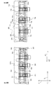
図1は、本発明の一実施形態にかかる戸吊装置を含むドア装置1の正面図である。図2は、図1の一部の拡大図である。なお、図1では、ドア2の一部が省略されている。図1および図2を参照して、ドア装置1は、たとえば、鉄道車両用のドア装置である。このドア装置1は、鉄道車両の車体(図示せず)の側壁を構造物として設置される。より具体的には、ドア装置1は、車体に形成された開口部に設置されている。ドア装置1は、この開口部を開閉するために設けられている。
FIG. 1 is a front view of a door apparatus 1 including a door suspension apparatus according to an embodiment of the present invention. FIG. 2 is an enlarged view of a part of FIG. In FIG. 1, a part of the
ドア装置1は、ドア2(2A,2B)と、ドア2を支持するための戸吊装置5(5A,5B)と、戸吊装置5を介して駆動力をドア2に付与するための開閉駆動機構6と、を有している。
The door device 1 includes a door 2 (2A, 2B), a door suspending device 5 (5A, 5B) for supporting the
ドア2は、車体の側壁に設けられた引戸であり、鉄道車両において乗客が乗降するために設けられた側戸を構成している。そして、ドア2は、2枚(ドア2A,2B)設けられており、戸吊装置5によって、車体に対して開方向X1および閉方向X2にスライド可能に支持(懸架)されている。なお、ドア2A,2Bは、それぞれ、単にドア2ともいう。ドア2は、開閉駆動機構6からの駆動力を、戸吊装置5を介して受けることで、開閉方向Xに変位する。
The
開閉駆動機構6は、ケーシング7と、駆動モータ8と、ピニオン9と、上ラック10と、下ラック11と、有している。
The open / close drive mechanism 6 has a casing 7, a
ケーシング7は、駆動モータ8およびピニオン9を収容している。ピニオン9は、駆動モータ8の出力軸に一体回転可能に連結されている。ピニオン9の上方に上ラック10が配置され、ピニオン9の下方に下ラック11が配置されている。
The casing 7 accommodates the
上ラック10および下ラック11は、鉄道車両の進行方向に沿って水平に延びるように配置されており、互いに平行である。これら上ラック10および下ラック11は、ピニオン9に噛み合っている。そして、上ラック10および下ラック11は、ピニオン9が回転することで、互いに逆方向にスライド移動する。上ラック10および下ラック11には、それぞれ、上連結ステー12および下連結ステー13が固定されている。
The
上連結ステー12および下連結ステー13は、開閉駆動機構6の対応するラック10,11から駆動力を与えられることで、開閉方向Xに変位可能である。各連結ステー12,13は、金属板部材である。上連結ステー12の上端部は、上ラック10の一端に、ねじ部材などを用いて固定されている。また、上連結ステー12の下端部は、ドア2Bを支持するための戸吊装置5Bにおける、後述する駆動側部材21の台座30に固定されている。これにより、上連結ステー12は、開閉駆動機構6の駆動力を、戸吊装置5Bに伝達する。
The upper connection stay 12 and the lower connection stay 13 can be displaced in the opening and closing direction X by being supplied with a driving force from the corresponding
下連結ステー13の上端部は、下ラック11の一端に、ねじ部材などを用いて固定されている。また、下連結ステー13の下端部は、ドア2Aを支持するための戸吊装置5Aにおいける、後述する駆動側部材21の台座30に固定されている。これにより、下連結ステー13は、開閉駆動機構6の駆動力を、戸吊装置5Aに伝達する。
The upper end portion of the
以上の構成により、駆動モータ8の正転運転および逆転運転に伴うピニオン9の回転によって、2枚のドア2A,2Bが開閉方向Xに連動して変位する。以上が、開閉駆動機構6の概略構成である。次に、戸吊装置5について説明する。
According to the above configuration, the two
戸吊装置5は、一方のドア2Aを支持するための戸吊装置5Aと、他方のドア2Bを支持するための戸吊装置5Bと、を有している。
The door suspension device 5 has a
なお、戸吊装置5Aと戸吊装置5Bとは、下連結ステー13と上連結ステー12とが開閉方向Xに非対称な形状である点以外、開閉方向Xに対称な構成を有している。よって、以下では、戸吊装置5A,5Bのうち、主に一方の戸吊装置5Aについて説明し、戸吊装置5Bの詳細な説明は省略する。また、以下では、ドア2(2A)が閉方向X2に変位する際の当該ドア2の進行方向先端側を戸先側といい、ドア2が開方向X1に変位する際の当該ドア2の進行方向先端側を戸尻側という。
The
図3は、戸吊装置5Aの正面図である。図4は、戸吊装置5Aの平面図である。図5は、戸吊装置5Aのうちの駆動側部材21などを示す正面図である。図6は、図5の平面図であり、戸吊装置5Aのうちの駆動側部材21などを示している。次に、図1〜図4を参照する。
FIG. 3 is a front view of the
戸吊装置5Aは、駆動側部材21と、静的調整機構22と、動的調整機構23と、弾性部材24と、戸車ユニット25と、ドア2(2A)を支持するハンガー26と、レール部材27と、を有している。
The
なお、ハンガー26については、一部の図面において、想像線である2点鎖線で示している。
The
駆動側部材21は、開閉駆動機構6からの駆動力を、弾性部材24、および、ハンガー26などを介してドア2に伝達するために設けられている。また、駆動側部材21は、開閉駆動機構6の下連結ステー13と、ドア2(ハンガー26)との開閉方向Xの相対位置を調整可能に構成されている。また、駆動側部材21は、開閉駆動機構6の下連結ステー13と、ドア2(ハンガー26)との間に作用する、弾性部材24の弾性反発力の初期値(初期セット荷重)を調整可能に構成されている。
The driving
なお、初期セット荷重とは、ドア2が静止状態にあり、且つ、ドア2に外力が作用していないときにおける、下連結ステー13とドア2(ハンガー26)との間に作用する、弾性部材24の弾性反発力をいう。駆動側部材21は、開閉方向Xに細長い形状に形成されており、開閉方向Xに沿って下連結ステー13と一体的に変位するように構成されている。
The initial set load is an elastic member acting between the
図7は、駆動側部材21の周辺の拡大正面図である。図8は、駆動側部材21の周辺の拡大平面図である。図2、および、図5〜図8を参照して、駆動側部材21は、開閉駆動機構6から駆動力を与えられることで、開閉方向Xに変位可能な部材である。この駆動側部材は、台座30と、第1部材31と、第2部材32と、を有している。
FIG. 7 is an enlarged front view of the periphery of the
台座30は、下連結ステー13が、ねじなどの固定部材を用いて固定される部分である。なお、戸吊装置5Bにおいては、下連結ステー13に代えて、上連結ステー12が、台座30に固定される。台座30は、第1部材31の戸先側端部に配置されている。
The
第1部材31は、開閉方向Xに延びる中空の軸状に形成されている。第1部材31は、台座30を介して、開閉駆動機構6の下連結ステー13からの駆動力を受ける。第1部材31の戸尻側には、第2部材32が配置されている。
The
第2部材32は、第1部材31とは別部材を用いて形成され、ハンガー26に動的調整機構23を介して連結される。第2部材32は、開閉方向Xに延びる中空の軸状に形成されており、第1部材31と開閉方向Xに並んでいる。第2部材32は、静的調整機構22を介して、第1部材31に固定されている。
The
静的調整機構22は、開閉方向Xにおいて、開閉駆動機構6に対するハンガー26の位置を調整するために設けられている、具体的には、静的調整機構22は、開閉方向Xにおける第1部材31と第2部材32との相対位置を調整可能に構成されている。静的調整機構22は、第1部材31および第2部材32のたとえば、上部に設けられている。静的調整機構22は、本実施形態では、ねじ式の調整機構である。
The
静的調整機構22は、第1部材31の戸尻側端部に形成された第1受け部33と、第2部材32の戸先側端部に形成された第2受け部34と、第2調整ボルト35と、一対のナット36,37と、を有している。
The
第1受け部33および第2受け部34は、それぞれ、貫通孔部33a、雌ねじ部34a、が形成された、小片状の部材である。第1受け部33および第2受け部34は、対応する第1部材31および第2部材32に固定されており、開閉方向Xに並んでいる。第2調整ボルト35は、たとえば、スタッドボルトであり、第1受け部33および第2受け部34の少なくとも一方にねじ結合を用いて結合されている。
Each of the first receiving
本実施形態では、第2調整ボルト35は、第1受け部33の貫通孔部33aに隙間をあけて挿入されている。また、第2調整ボルト35は、第2受け部34の雌ねじ部34aにねじ結合を用いて結合されつつ、溶接によって第2受け部34に固定されている。第2調整ボルト35は、第2受け部34から戸先側に延びている。第2調整ボルト35には、ナット36,37がねじ結合している。
In the present embodiment, the
ナット36,37は、第1受け部33を開閉方向Xに挟むように配置されており、第1受け部33に締結されている。スパナなどの工具を用いて、第2調整ボルト35に対するナット36,37の開閉方向Xの位置を調整することで、第1部材31と第2部材32との開閉方向Xの相対位置を調整することができる。すなわち、第1部材31に連結された開閉駆動機構6の下連結ステー13と、第2部材32に動的調整機構23を介して連結されたハンガー26(ドア2)との相対位置を調整できる。
The nuts 36 and 37 are disposed so as to sandwich the first receiving
また、ナット36,37は、ロックナットとしての機能も有しており、第2調整ボルト35を第1受け部33に固定している。なお、第1受け部33を第2部材32に固定し、第2受け部34を第1部材31に固定してもよい。
The nuts 36 and 37 also have a function as a lock nut, and fix the
静的調整機構22に隣接して、動的調整機構23が設けられている。
A
動的調整機構23は、駆動側部材21とハンガー26との間に作用する荷重の初期値(セット荷重)を調整するための機構として設けられている。動的調整機構23は、第2部材32に支持されるとともに、ハンガー26に受けられることで、第2部材32(駆動側部材21)とハンガー26とから荷重を受ける弾性部材24のばね長を設定する。本実施形態では、動的調整機構23は、ねじ機構である。動的調整機構23は、本実施形態では、第2部材32の戸尻側端部に配置されている。
The
動的調整機構23は、第1調整ボルト38と、固定ナット39と、ロックナット40と、を有している。
The
第1調整ボルト38は、駆動側部材21とハンガー26との間に作用する荷重の初期値(初期セット荷重)を調整するためのボルト部材として設けられている。第1調整ボルト38は、開閉方向Xに沿って延びている。第1調整ボルト38は、駆動側部材21の第2部材32の下部に隣接して配置されており、当該第2部材32と平行である。第1調整ボルト38と第2調整ボルト35の位置とは、戸吊装置5Aの上下方向Z、および、開閉方向Xの少なくとも一方(本実施形態では、双方)にずらされている。本実施形態では、上下方向Zにおける第1調整ボルト38の位置は、第2調整ボルト35の位置よりも低い。また、第1調整ボルト38は、第2調整ボルト35から戸尻側に進んだ位置に配置されている。
The
第1調整ボルト38は、頭付きボルトであり、頭部38aと、雄ねじ部38bとを有している。
The
頭部38aは、本発明の「被受け部」の一例である。頭部38aは、たとえば、六角形状の頭部であり、第1調整ボルト38の戸先側端部に配置されている。頭部38aの端面は、開閉方向Xにおけるハンガー26の中間部において、ハンガー26の後述する縁部98aに受けられている。すなわち、頭部38aは、第1調整ボルト38から戸先側へ向かう力をハンガー26の後述する縁部98aによって受けられるように、当該ハンガー26に受けられている。
The
これにより、頭部38aは、第1調整ボルト38に作用する軸力をハンガー26の縁部98aで受けられるように配置されている。平面視(図8)において、頭部38aの一部は、駆動側部材21の第2部材32に隠れるように配置されている。これにより、ドア2の厚み方向Yにおける戸吊装置5の幅は、短い。
Thus, the
頭部38aから戸尻側に向けて、雄ねじ部38bが延びている。すなわち第1調整ボルト38は、戸尻側に向けて延びるように配置されている。このように、ハンガー26から第1調整ボルト38が延びる方向と、駆動側部材21から第2調整ボルト35が延びる方向とは、反対向きに設定されている。
A
雄ねじ部38bは、開閉方向Xに延びている。雄ねじ部38bには、固定ナット39の雌ねじ部39aがねじ結合している。固定ナット39は、駆動側部材21の第2部材32に設けられたナット部材であり、駆動側部材21の一部を構成している。固定ナット39は、ハンガー26の切欠部98内に配置されている。固定ナット39には、ロックナット40が締結されている。ロックナット40は、第1調整ボルト38を固定ナット39に固定するために設けられており、本実施形態では、頭部38aと固定ナット39との間に配置されている。
The
動的調整機構23においては、スパナなどの工具を用いて、固定ナット39に対する第1調整ボルト38の位置を調整し、その後、ロックナット40で第1調整ボルト38と固定ナット39とを締結する。これにより、駆動側部材21に対するハンガー26の位置調整を通じて、弾性部材24の圧縮量、すなわち、初期セット荷重を調整できる。上記の構成を有する動的調整機構23を開閉方向Xに挟むようにして、戸車ユニット25が配置されている。
In the
図9は、図3の戸車ユニット25の周辺の拡大正面図である。図10は、図4の戸車ユニット25の周辺の拡大平面図である。図2、図3、および図9を参照して、戸車ユニット25は、駆動側部材21からの駆動力をハンガー26に伝達することで、ドア2を開閉方向Xに変位させる。
FIG. 9 is an enlarged front view around the
また、戸車ユニット25は、ドア2に乗客がもたれかかった状態などの状態において、開閉駆動機構6がドア2を開こうとしたときに、ドア2が上下方向Zにがたつくように動くこと(ドア踊り)を抑制するように構成されている。戸車ユニット25の間に駆動側部材21が配置されている。
In addition, when the opening / closing drive mechanism 6 tries to open the
戸車ユニット25は、第1サブユニット41と、第2サブユニット42と、を有している。
The door and
第1サブユニット41は、駆動側部材21の第1部材31の戸先側(ドア2の戸先側)に配置されており、ハンガー26およびドア2のそれぞれの戸先側端部を支持している。第2サブユニット42は、駆動側部材21の第2部材32の戸尻側(ドア2の戸尻側)に配置されており、ハンガー26およびドア2のそれぞれの戸尻側端部を支持している。第1サブユニット41と第2サブユニット42とは、後述するように、駆動側部材21を貫通する連結部材91を介して連結されている。
The
第1サブユニット41および第2サブユニット42は、それぞれ、本発明の「駆動側部材とハンガーとの間に所定のしきい値以上の荷重が作用した場合に、開閉方向へのハンガーの移動を案内する戸車をレールへ押し付ける押付機構」の一例である。また、第1サブユニット41および第2サブユニット42は、それぞれ、本発明の「駆動側部材とハンガーとが開閉方向に相対変位する動作を、被押当戸車が一対のレールの一方に押し当てられる動作に変換する運動変換機構」の一例である。
The
図11は、図9のXI−XI線に沿う断面図である。図12は、図9のXII−XII線に沿う断面図である。図13は、図9のXIII−XIII線に沿う断面図である。なお、本実施形態では、断面図について、切断面の奥側に表れる部材の表示を省略している場合がある。 11 is a cross-sectional view taken along the line XI-XI in FIG. 12 is a cross-sectional view taken along the line XII-XII in FIG. FIG. 13 is a cross-sectional view taken along the line XIII-XIII of FIG. In addition, in this embodiment, the display of the member which appears in the back side of a cut surface may be abbreviate | omitted about sectional drawing.
図1、図3、および、図9〜図13を参照して、第1サブユニット41の説明に先んじて、レール部材27を説明する。レール部材27は、開閉方向Xに沿って延びており、車体に固定されている。レール部材27は、開閉方向Xへのハンガー26の変位を案内するために設けられている。本実施形態では、レール部材27は、金属部材などを用いて形成された一体成形品である。レール部材27は、開閉方向Xと直交する断面において、略U字状に形成されている。
The
レール部材27は、上下一対のレールとしての下レール43および上レール44と、これらのレール43,44を互いに連結する連結部45と、を有している。
The
下レール43は、後述する第1常時接触戸車51および第2常時接触戸車71を受けてこれらの常時接触戸車51,71と転がり接触する部分として設けられている。下レール43は、開閉方向Xに延びている。下レール43は、凸条部43aを有している。凸条部43aは、開閉方向Xに沿って延びており、上向きに凸湾曲した形状を有している。
The
上レール44は、後述する第1被押当戸車52および第2被押当戸車72を受けてこれらの被押当戸車52,72と転がり接触する部分として設けられている。上レール44は、開閉方向Xに延びている。上レール44は、凸条部44aを有している。凸条部44aは、開閉方向Xに沿って延びており、下向きに凸湾曲した形状を有している。上レール44において、厚み方向Yにおける凸条部44aの両端には、一対の傾斜面44b,44cが形成されている。
The
一対の傾斜面44b,44cは、滑らかな湾曲状に形成されており、厚み方向Yに沿って凸条部44aから遠ざかるに従い、下方に進むように傾斜している。上記の構成を有するレール部材27によって、第1サブユニット41および第2サブユニット42が支持されている。
The pair of
第1サブユニット41は、第1常時接触戸車51と、第1被押当戸車52と、第1リンク機構53と、を有している。第1常時接触戸車51および第1被押当戸車52は、開閉方向Xへのハンガー26の変位を案内するために設けられており、下レール43および上レール44の間に配置されている。
The
第1常時接触戸車51は、レール部材27の下レール43に常時接触する常時接触戸車として設けられている。第1常時接触戸車51は、戸吊装置5Aの自重を受けながら下レール43に接触し、ドア2の開閉動作に伴って、下レール43上を転がる。第1常時接触戸車51は、第1サブユニット41の戸先側端部寄りに配置されている。第1常時接触戸車51は、円筒状に形成されている。第1常時接触戸車51の外周面は、下レール43の凸条部43aに嵌まる形状に形成されている。
The first constant
具体的には、第1常時接触戸車51は、厚み方向Yにおける当該第1常時接触戸車51の外周面の中間部に溝部51aを有している。この溝部51aは、環状に形成されており、下レール43の凸条部43aに嵌まることで、当該下レール43に転がり接触している。第1常時接触戸車51に隣接して、第1被押当戸車52が配置されている。
Specifically, the first constant
第1被押当戸車52は、レール部材27の上レール44に一時的に押し当てられる戸車として設けられている。第1被押当戸車52は、上レール44に押し付けられることで、ドア2が上下方向Zにがたつくこと(ドア踊り)を抑制する。
The first pushed
第1被押当戸車52は、ドア2の開閉動作に伴って、上レール44上を転がることが可能である。第1被押当戸車52は、第1サブユニット41の戸尻側端部寄りに配置されている。第1被押当戸車52の形状は、第1常時接触戸車51の形状と同じであり、円筒状に形成されている。第1被押当戸車52の外周面は、上レール44の凸条部44aに嵌まる形状に形成されている。
The first pushed
具体的には、第1被押当戸車52は、厚み方向Yにおける当該第1被押当戸車52の外周面の中間部に溝部52aを有している。この溝部52aは、環状に形成されており、上レール44の凸条部44aに嵌まっている。また、第1被押当戸車52の外周面のうち、厚み方向Yにおける溝部52aの両側方には、一対の傾斜面52b,52cが形成されている。これらの傾斜面52b,52cは、上レール44の傾斜面44b,44cの形状に対応する形状に形成されている。
Specifically, the first driven
第1被押当戸車52の溝部52aに上レール44の凸条部44aが嵌まった状態で、互いの傾斜面44b,52b;44c,52cが接触することで、第1被押当戸車52は、上レール44と転がり接触する。これら第1常時接触戸車51および第1被押当戸車52は、第1リンク機構53に連結されている。
When the
第1リンク機構53は、駆動側部材21とハンガー26とが開閉方向Xに相対変位する動作を、第1被押当戸車52が上レール44に押し当てられる動作に変換する運動変換機構として設けられている。
The
第1リンク機構53は、第1常時接触戸車支持部材55と、第1支軸56aと、第1リンク部材57と、第2支軸58aと、第2リンク部材59と、を有している。
The
第1常時接触戸車支持部材55は、ハンガー26に固定され、且つ、第1常時接触戸車支持部材55を支持し、且つ、第1リンク部材57を介して第2リンク部材59に連結される部分として設けられている。本実施形態では、第1常時接触戸車支持部材55は、2つの板金部材を組み合わせることで形成されている。第1常時接触戸車支持部材55は、底面視(図11)において、U字状に形成されている。また、第1常時接触戸車支持部材55は、正面視において、開閉方向Xに細長い形状に形成されている。
A portion that is fixed to the
第1常時接触戸車支持部材55は、一対の側壁55a,55bと、端壁55cと、を有している。
The first constant contact door
一対の側壁55a,55bは、厚み方向Yと直交する方向に延びる、板状部分である。各側壁55a,55bは、同じ形状に形成されている。各側壁55a,55bの底面は、水平に延びている。一方、各側壁55a,55bの上面は、起伏を有する形状に形成されている。具体的には、各側壁55a,55bの上面は、開閉方向Xにおける当該上面の戸先側端部から中間部までは、水平に延びている。
The pair of
そして、この上面は、開閉方向Xの途中部において、下向きに窪む凹状面55dを有している。さらに、開閉方向Xにおけるこの上面の戸尻側端部は、上向きに凸となる凸状面55eを有している。凹状面55dと凸状面55eは、それぞれ、正面視において、円弧状に形成されており、互いに連続している。これら一対の側壁55a,55bの戸先側端部は、端壁55cによって互いに連続している。
The upper surface has a
各側壁55a,55bの戸先側部分には、貫通孔55fが形成されている。この貫通孔55fには、円筒状のブッシュ60が挿入されている。ブッシュ60の中間部の外径は、ブッシュ60の両端部の外径よりも大きく設定されている。ブッシュ60の中間部は、側壁55a,55bに挟まれている。ブッシュ60は、一方の側壁55bに溶接などによって固定されている。ブッシュ60は、玉軸受などの軸受を介して第1常時接触戸車51を支持している。これにより、第1常時接触戸車支持部材55は、ブッシュ60などを介して、第1常時接触戸車51を回転自在に、且つ、一体的に変位可能に支持している。
A through
また、このブッシュ60は、ハンガー26に形成された貫通孔261を貫通している。このブッシュ60の内周面には雌ねじ部が形成されており、ブッシュ60は、ボルト61とねじ結合している。ボルト61とブッシュ60によって、第1常時接触戸車支持部材55がハンガー26に固定されている。
Further, the
また、第1常時接触戸車支持部材55は、第1支軸56aを支持している。第1支軸56aは、厚み方向Yに延びる軸部材であり、ボルト56の軸部として設けられている。ボルト56は、頭付きのボルトである。ボルト56は、各側壁55a,55bに形成された貫通孔(図示せず)を貫通しており、ブッシュなどを介して、第1リンク部材57を、第1支軸56a回りに回転可能に支持している。これにより、第1常時接触戸車支持部材55は、第1支軸56aを支持している。また、ボルト56は、ハンガー26と第1常時接触戸車支持部材55の側壁55aとを互いに固定している。これにより、第1支軸56aは、ハンガー26と一体に変位する。
Moreover, the 1st always contact door
第1リンク部材57は、開閉方向Xにおける駆動側部材21とハンガー26との相対移動に伴い第1支軸56a回りを揺動可能な部材として設けられている。第1リンク部材57は、ブロック状に形成された部材であり、正面視において、細長く延びる形状を有している。第1リンク部材57の一端側(下端側)部分には、前述したように、第1支軸56aが連結されており、この第1支軸56aなどを介して第1常時接触戸車支持部材55に支持されている。第1リンク部材57の他端側(上端側)部分には、第2支軸58aが連結されている。
The
第2支軸58aは、第1支軸56aと平行に延びて第1リンク部材57と第2リンク部材59とを相対回転可能に連結するために設けられている。第2支軸58aは、厚み方向Yに延びる軸部材であり、ボルト58の軸部として設けられている。ボルト58は、頭付きのボルトである。ボルト58の頭部58bは、ハンガー26に形成されたガイド孔部262内に配置されている。ボルト58(第2支軸58a)は、第2リンク部材59の戸先側部分を貫通しており、ブッシュなどを介して、第2リンク部材59を、第2支軸58a回りに回転可能に支持している。これにより、第2リンク部材59は、第1リンク部材57に対して第2支軸58a回りを揺動可能である。
The
第2リンク部材59は、第1リンク部材57に連結され、且つ、第1被押当戸車52を支持し、且つ、駆動側部材21に後述する連結部材91および弾性部材24を介して連結されている。第2リンク部材59は、本発明の「戸車用ブラケット」の一例である。本実施形態では、第2リンク部材59は、2つの板金部材を組み合わせることで形成されている。第2リンク部材59は、底面視(図11)において、U字状に形成されている。また、第2リンク部材59は、正面視において、開閉方向Xに細長い形状に形成されている。
The
第2リンク部材59は、一対の側壁59a,59bと、端壁59cと、を有している。
The
一対の側壁59a,59bは、厚み方向Yと直交する方向に延びる、板状部分である。各側壁59a,59bは、同じ形状に形成されている。各側壁59a,59bの上面は、水平に延びている。一方、各側壁59a,59bの底面は、起伏を有する形状に形成されている。具体的には、各側壁59a,59bの下面は、開閉方向Xにおける当該下面の戸尻側端部から中間部までは、水平に延びている。
The pair of
そして、この下面は、開閉方向Xの途中部において、上向きに窪む凹状面59dを有している。さらに、開閉方向Xにおけるこの下面の戸先側端部は、下向きに凸となる凸状面59eを有している。凹状面59dと凸状面59eは、それぞれ、正面視において、円弧状に形成されており、互いに連続している。
The lower surface has a concave surface 59 d that is recessed upward in the middle in the opening and closing direction X. Furthermore, the end on the door tip side of the lower surface in the opening and closing direction X has a
なお、本実施形態では、第2リンク部材59の下面と第1常時接触戸車支持部材55の上面とは非接触の状態となるように配置されているけれども、この通りでなくてもよい。たとえば、上記下面と上面とが互いに接触してもよい。この場合、下面の凹状面59dおよび凸条面59eは、上面の凹状面55dおよび凸条面55eとの接触により、カム機構を形成する。このカム機構においては、第2リンク部材59が第1常時接触戸車支持部材55に対して戸尻側に変位する動作を、第2リンク部材59が上方に変位する変位に変換することとなる。
In the present embodiment, although the lower surface of the
上記一対の側壁59a,59bの戸尻側端部は、端壁59cによって互いに連続している。
Ends on the rear end of the pair of
各側壁59a,59bの戸尻側部分には、貫通孔59fが形成されている。この貫通孔59fには、円筒状のブッシュ62が挿入されている。ブッシュ62の中間部の外径は、ブッシュ62の両端部の外径よりも大きく設定されている。ブッシュ62の中間部は、側壁59a,59bに挟まれている。ブッシュ62は、一方の側壁59bに溶接などによって固定されている。ブッシュ62は、玉軸受などの軸受を介して第1被押当戸車52を支持している。これにより、第2リンク部材59は、ブッシュ62などを介して、第1被押当戸車52を回転自在に、且つ、一体的に変位可能に支持している。また、このブッシュ62の一端部は、ハンガー26に形成されたガイド孔部263内に配置されている。なお、ブッシュ60とブッシュ62とは、同じ部材であり、部品の汎用性が高められている。
A through
ブッシュ62の一端には、円筒状のカラー63が嵌め込まれている。このカラー63は、ボルト64を用いてブッシュ62に固定されている。カラー63は、後述するように、ハンガー26の側壁部94に形成されたガイド孔部263に嵌められている。
A
上記の構成を有する第1サブユニット41は、連結部材91を介して、第2サブユニット42に連結されている。
The
図14は、図9のXIV−XIV線に沿う断面図である。図15は、図9のXV−XV線に沿う断面図である。図16は、図9のXVI−XVI線に沿う断面図である。次に、図2、図3、図9および図14〜図16を参照する。 FIG. 14 is a cross-sectional view taken along line XIV-XIV of FIG. FIG. 15 is a cross-sectional view taken along the line XV-XV in FIG. 16 is a cross-sectional view taken along the line XVI-XVI in FIG. Next, FIG. 2, FIG. 3, FIG. 9, and FIGS. 14 to 16 will be referred to.
第2サブユニット42は、第2常時接触戸車71と、第2被押当戸車72と、第2リンク機構73と、を有している。第2常時接触戸車71および第2被押当戸車72は、開閉方向Xへのハンガー26の変位を案内するために設けられており、下レール43および上レール44の間に配置されている。
The
第2常時接触戸車71は、レール部材27の下レール43に常時接触する常時接触戸車として設けられている。第2常時接触戸車71は、戸吊装置5Aの自重を受けながら下レール43に接触し、ドア2の開閉動作に伴って、下レール43上を転がる。第2常時接触戸車71は、第2サブユニット42の戸先側端部寄りに配置されている。第2常時接触戸車71は、第1常時接触戸車51と同じ形状に形成されている。具体的には、第2常時接触戸車71は、円筒状に形成されている。第2常時接触戸車71の外周面は、下レール43の凸条部43aに嵌まる形状に形成されている。
The second constant
より具体的には、第2常時接触戸車71は、厚み方向Yにおける当該第2常時接触戸車71の外周面の中間部に溝部71aを有している。この溝部71aは、環状に形成されており、下レール43の凸条部43aに嵌まることで、当該下レール43に転がり接触している。第2常時接触戸車71に隣接して、第2被押当戸車72が配置されている。
More specifically, the second constant
第2被押当戸車72は、レール部材27の上レール44に一時的に押し当てられる戸車として設けられている。第2被押当戸車72は、上レール44に押し付けられることで、ドア2が上下方向Zにがたつくこと(いわゆるドア踊り)を抑制する。第2被押当戸車72は、ドア2の開閉動作に伴って、上レール44上を転がることが可能である。第2被押当戸車72は、第2サブユニット42の戸尻側端部寄りに配置されている。第2被押当戸車72の形状は、第2常時接触戸車71の形状と同じであり、円筒状に形成されている。第2被押当戸車72の外周面は、上レール44の凸条部44aに嵌まる形状に形成されている。
The second driven
具体的には、第2被押当戸車72は、厚み方向Yにおける当該第2被押当戸車72の外周面の中間部に溝部72aを有している。この溝部72aは、環状に形成されており、上レール44の凸条部44aに嵌まっている。また、第2被押当戸車72の外周面のうち、厚み方向Yにおける溝部72aの両側方には、一対の傾斜面72b,72cが形成されている。これらの傾斜面72b,72cは、上レール44の傾斜面44b,44cの形状に対応する形状に形成されている。
Specifically, the second driven
第2被押当戸車72の溝部72aに上レール44の凸条部44aが嵌まった状態で、互いの傾斜面44b,72b;44c,72cが接触することで、第2被押当戸車72は、上レール44と転がり接触する。これら第2常時接触戸車71および第2被押当戸車72は、第2リンク機構73に連結されている。
When the
第2リンク機構73は、駆動側部材21とハンガー26とが開閉方向Xに相対変位する動作を、第2被押当戸車72が上レール44に押し当てられる動作に変換する運動変換機構として設けられている。
The
第2リンク機構73は、第2常時接触戸車支持部材75と、第1支軸76aと、第1リンク部材77と、第2支軸78aと、第2リンク部材79と、を有している。
The
第2常時接触戸車支持部材75は、ハンガー26とは弾性部材24の弾性変形に伴って相対変位可能に構成され、且つ、第2常時接触戸車71を支持し、且つ、第1支軸76aを支持するとともに、第1リンク部材77を介して第2リンク部材79に連結される部分として設けられている。第2常時接触戸車支持部材75は、本発明の「戸車用ブラケット」の一例である。本実施形態では、第2常時接触戸車支持部材75は、2つの板金部材を組み合わせることで形成されている。第2常時接触戸車支持部材75は、底面視(図14)において、U字状に形成されている。また、第2常時接触戸車支持部材75は、正面視において、開閉方向Xに細長い形状に形成されている。第2常時接触戸車支持部材75は、第2リンク部材59と同一形状に形成されている。これにより、第2常時接触戸車支持部材75と第2リンク部材59の汎用性を高くできる。
The second constant-contact door
第2常時接触戸車支持部材75は、一対の側壁75a,75bと、端壁75cと、を有している。
The second always-contacting
一対の側壁75a,75bは、厚み方向Yと直交する方向に延びる、板状部分である。各側壁75a,75bは、同じ形状に形成されている。各側壁75a,75bの底面は、水平に延びている。一方、各側壁75a,75bの上面は、起伏を有する形状に形成されている。具体的には、各側壁75a,75bの上面は、開閉方向Xにおける当該上面の戸先側端部から中間部までは、水平に延びている。
The pair of
そして、この上面は、開閉方向Xの途中部において、下向きに窪む凹状面75dを有している。さらに、開閉方向Xにおけるこの上面の戸尻側端部は、上向きに凸となる凸状面75eを有している。凹状面75dと凸状面75eは、それぞれ、正面視において、円弧状に形成されており、互いに連続している。これら一対の側壁75a,75bの戸先側端部は、端壁75cによって互いに連続している。端壁75cは、上記2つの板金部材の一端同士を溶接などによって互いに固定することで形成されている。
The upper surface has a
各側壁75a,75bの戸先側部分には、貫通孔75fが形成されている。この貫通孔75fには、円筒状のブッシュ80が挿入されている。ブッシュ80の中間部の外径は、ブッシュ80の両端部の外径よりも大きく設定されている。ブッシュ80の中間部は、側壁75a,75bに挟まれている。ブッシュ80は、一方の側壁75bに溶接などによって固定されている。ブッシュ80は、玉軸受などの軸受を介して第2常時接触戸車71を支持している。これにより、第2常時接触戸車支持部材75は、ブッシュ80などを介して、第2常時接触戸車71を回転自在に、且つ、一体的に変位可能に支持している。
A through
また、このブッシュ80の一端部は、ハンガー26に形成されたガイド孔部264内に配置されている。ブッシュ80の一端には、円筒状のカラー83が嵌め込まれている。このカラー83は、ボルト81を用いてブッシュ80に固定されている。カラー83は、後述するように、ハンガー26の側壁部94に形成されたガイド孔部265に嵌められている。
Further, one end of the
また、第2常時接触戸車支持部材75は、第1支軸76aを支持している。第1支軸76aは、厚み方向Yに延びる軸部材であり、ボルト76の軸部として設けられている。ボルト76は、頭付きのボルトである。ボルト76は、各側壁75a,75bに形成された貫通孔(図示せず)を貫通しており、ブッシュなどを介して、第1リンク部材77を、第1支軸76a回りに回転可能に支持している。これにより、第2常時接触戸車支持部材75は、第1支軸76aを支持している。ボルト76の頭部76bは、ハンガー26に形成されたガイド孔部264内に配置されている。
Further, the second always-contacting
第1リンク部材77は、開閉方向Xにおける駆動側部材21とハンガー26との相対移動に伴い第1支軸76a回りを揺動可能な部材として設けられている。第1リンク部材57と第1リンク部材77とは、同じ形状の部品であり、部品の汎用性が高められている。より具体的には、第1リンク部材77は、ブロック状に形成された部材であり、正面視において、細長く延びる形状を有している。第1リンク部材77の一端側(下端側)部分には、前述したように、第1支軸76aが連結されており、この第1支軸76aなどを介して第2常時接触戸車支持部材75に支持されている。
The
本実施形態では、第1リンク機構53の第1リンク部材57は、当該第1リンク機構53の第1支軸56aの上方に延びている。同様に、第2リンク機構73の第1リンク部材77は、当該第2リンク機構73の第1支軸76aの上方に延びている。
In the present embodiment, the
また、戸吊装置5Aを正面視した場合に、各リンク機構53,73の第1リンク部材57,77は、上下方向Zに対して傾斜して延びている。また、第1リンク機構53の第1リンク部材57と、第2リンク機構73の第1リンク部材77は、上下方向Zに対する傾斜の向きが反対である。本実施形態では、第1リンク部材57は、下方に進むほど戸尻側に進むように配置されている。一方、第1リンク部材57は、下方に進むほど戸先側に進むように配置されている。第1リンク部材77の他端側(上端側)部分には、第2支軸78aが連結されている。
In addition, when the
第2支軸78aは、第1支軸76aと平行に延びて第1リンク部材77と第2リンク部材79とを相対回転可能に連結するために設けられている。第2支軸78aは、厚み方向Yに延びる軸部材であり、ボルト78の軸部として設けられている。ボルト78は、頭付きのボルトである。ボルト78(第2支軸78a)は、第2リンク部材79に形成された貫通孔(図示せず)を貫通しており、ブッシュなどを介して、第2リンク部材79を、第2支軸78a回りに回転可能に支持している。これにより、第2リンク部材79は、第1リンク部材77に対して第2支軸78a回りを揺動可能である。また、ボルト78は、ハンガー26と第2リンク部材59の側壁79aとを互いに固定している。これにより、第2支軸58aおよび第2リンク部材59は、ハンガー26と一体に変位する。
The
第2リンク部材79は、第1リンク部材77に連結され第2被押当戸車72を支持している。また、第2リンク部材79は、第1リンク部材77、第2常時接触戸車支持部材75、連結部材91および弾性部材24を介して、駆動側部材21に連結されている。本実施形態では、第2リンク部材79は、2つの板金部材を組み合わせることで形成されている。第2リンク部材79は、底面視(図14)において、U字状に形成されている。また、第2リンク部材79は、正面視において、開閉方向Xに細長い形状に形成されている。第2リンク部材79は、第1常時接触戸車支持部材55と同一形状に形成されている。これにより、第2リンク部材79と第1常時接触戸車支持部材55の汎用性を高くできる。
The
第2リンク部材79は、一対の側壁79a,79bと、端壁79cと、を有している。
The
一対の側壁79a,79bは、厚み方向Yと直交する方向に延びる、板状部分である。各側壁79a,79bは、同じ形状に形成されている。各側壁79a,79bの上面は、水平に延びている。一方、各側壁79a,79bの底面は、起伏を有する形状に形成されている。具体的には、各側壁79a,79bの下面は、開閉方向Xにおける当該下面の戸尻側端部から中間部までは、水平に延びている。
The pair of
そして、この下面は、開閉方向Xの途中部において、上向きに窪む凹状面79dを有している。さらに、開閉方向Xにおけるこの下面の戸先側端部は、下向きに凸となる凸状面79eを有している。凹状面79dと凸状面79eは、それぞれ、正面視において、円弧状に形成されており、互いに連続している。
And this lower surface has the
なお、本実施形態では、第2リンク部材79の下面と第2常時接触戸車支持部材75の上面とは非接触の状態となるように配置されているけれども、この通りでなくてもよい。たとえば、上記下面と上面とが互いに接触してもよい。この場合、下面の凸状面79eは、上面の凸状面75eとの接触により、カム機構を形成する。このカム機構においては、第2リンク部材79が第2常時接触戸車支持部材75に対して戸先側に変位する動作を、第2リンク部材79が上方に変位する変位に変換することとなる。
In the present embodiment, although the lower surface of the
上記一対の側壁79a,79bの戸尻側端部は、端壁79cによって互いに連続している。
Ends on the rear end of the pair of
各側壁79a,79bの戸尻側部分には、貫通孔79fが形成されている。この貫通孔79fには、円筒状のブッシュ82が挿入されている。ブッシュ82の中間部の外径は、ブッシュ82の両端部の外径よりも大きく設定されている。ブッシュ82の中間部は、側壁79a,79bに挟まれている。ブッシュ82は、一方の側壁79bに溶接などによって固定されている。ブッシュ82は、玉軸受などの軸受を介して第2被押当戸車72を支持している。これにより、第2リンク部材79は、ブッシュ82などを介して、第2被押当戸車72を回転自在に、且つ、一体的に変位可能に支持している。また、このブッシュ82は、ハンガー26に形成された貫通孔266を貫通している。このブッシュ82の内周面には雌ねじ部が形成されており、ブッシュ82は、ボルト84とねじ結合している。ボルト84とブッシュ82によって、第2リンク部材79がハンガー26に固定されている。なお、ブッシュ80,82は同じ形状の部材であり、部品の汎用性が高められている。
A through
次に、上記の構成を有する第1サブユニット41と第2サブユニット42とを連結する連結部材91について、より具体的に説明する。
Next, the connecting
図3および図4を参照して、連結部材91は、第1リンク機構53の第2リンク部材59と、第2リンク機構73の第2常時接触戸車支持部材75とを一体的に変位可能に連結している。また、連結部材91は、ハンガー26と開閉方向Xに連動して変位可能に、且つ、弾性部材24の弾性変形に伴って開閉方向Xに相対変位可能に構成されている。
With reference to FIGS. 3 and 4, the connecting
連結部材91は、開閉方向Xに延びる丸軸部材として設けられている。連結部材91の一端部は、第1リンク機構53の第2リンク部材59の端壁59cに固定されている。連結部材91の他端部は、第2リンク機構73の第2常時接触戸車支持部材75の端壁75cに固定されている。
The
また、連結部材91は、各リンク機構53,73と駆動側部材21とを連結している。具体的には、駆動側部材21の第1部材31に、開閉方向Xに延びる嵌合孔部31aが形成されているとともに、第2部材32に、開閉方向Xに延びる嵌合孔部32aが形成されている。連結部材91は、これらの嵌合孔部31a,32aを貫通している。
Further, the connecting
嵌合孔部31a,32aには、図示しないブッシュが配置されており、連結部材91を支持している。これにより、連結部材91は、第1リンク機構53,73と駆動側部材21とを開閉方向Xに相対的にスライド可能に、且つ、開閉方向Xと直交する方向に連動して変位可能に連結されている。また、連結部材91には、弾性部材24が嵌め入れられている。連結部材91は、本発明の「ばねガイド部材」の一例であり、弾性部材24としてのコイルばねの伸縮動作を案内する。
A bush (not shown) is disposed in the fitting holes 31 a and 32 a to support the connecting
弾性部材24は、駆動側部材21とハンガー26との間に作用する開閉方向Xの荷重に応じて弾性変形することで、開閉方向Xにおける駆動側部材21とハンガー26(ドア2A)との相対変位を許容するために設けられている。弾性部材24は、開閉方向Xに沿う荷重を受けることで弾性変形する部材であり、本実施形態では、開閉方向Xに延びるコイルばねである。弾性部材24は、連結部材91の戸尻側端部寄りに配置されている。
The
弾性部材24は、駆動側部材21と開閉方向Xに並んでおり、且つ、各リンク機構53,73とは開閉方向Xに並んでいる。弾性部材24の戸先側端部は、駆動側部材21の第2部材32に受けられている。また、弾性部材24の戸尻側端部は、第2リンク機構73の第2常時接触戸車支持部材75の端壁75cに受けられている。ドア2の静止時、弾性部材24は、駆動側部材21と第2常時接触戸車支持部材75との間で圧縮されて弾性反発力(初期セット荷重)をこれら駆動側部材21および第2常時接触戸車支持部材75に付与している。これにより、駆動側部材21の第1部材31は、第1リンク機構53の第2リンク部材59の端壁59cに加圧されている。
The
上記の構成により、駆動側部材21は、弾性部材24を介して、連結部材91、各リンク機構53,73と開閉方向Xに一体的に変位可能に連結している。また、駆動側部材21は、弾性部材24の弾性変形に伴って駆動側部材21と第2リンク部材59とを開閉方向Xに相対変位可能に連結するように構成されている。すなわち、連結部材91は、弾性部材24と協働して、各リンク機構53,73と駆動側部材21とを連動して変位可能に連結している。また、連結部材91は、弾性部材24の弾性変形に伴って駆動側部材21と第2リンク部材59とを開閉方向Xに相対変位可能に連結している。
According to the above configuration, the
図7および図8を参照して、本実施形態では、弾性部材24の中心軸線L1、および、動的調整機構23の第1調整ボルト38の中心軸線L2は、互いにずらされている。具体的には、中心軸線L1は、中心軸線L2の上方で、且つ、厚み方向Yの一方側(図7における紙面の奥側)に位置している。また、弾性部材24の中心軸線L1、および、静的調整機構22の第2調整ボルト35の中心軸線L3は、互いにずらされている。具体的には、中心軸線L1は、中心軸線L3の下方で、且つ、厚み方向Yの一方側に位置している。弾性部材24に隣接する位置に、ハンガー26が配置されている。
7 and 8, in the present embodiment, the central axis L1 of the
図17は、図2に示す構成の一部を破断して示す拡大図である。図3、図7、図8、図12、および、図17を参照して、ハンガー26は、駆動側部材21の変位と連動して開閉方向Xに変位可能に構成され、且つ、ドア2を支持する部分として設けられている。ハンガー26は、ドア2に固定されているとともに、第1リンク機構53の第1常時接触戸車支持部材55に固定され、且つ、第2リンク機構73の第2リンク部材79に固定されている。そして、ハンガー26は、動的調整機構23の第1調整ボルト38に受けられている。以下、ハンガー26の構成について、より具体的に説明する。
FIG. 17 is an enlarged view showing a part of the configuration shown in FIG. 2 broken away. Referring to FIGS. 3, 7, 8, 12 and 17, the
ハンガー26は、開閉方向Xに沿って見たときに、略L字状に形成されており、厚み方向Yにおいて、各リンク機構53,73に対して隣接して配置されるとともに、各リンク機構53,73の下方に配置されている。ハンガー26は、板金部材である。すなわち、ハンガー26は、切断加工および曲げ加工が施され開閉方向Xに延びる金属板を用いて形成されている。開閉方向Xにおいて、ハンガー26は、戸吊装置5Aの戸先側端部から戸尻側端部にかけて延びている。
The
ハンガー26は、ドア固定部92と、傾斜部93と、側壁部94と、を有している。
The
ドア固定部92は、当該ドア固定部92の厚み方向が上下方向Zとなるように配置され、開閉方向Xに細長い部分である。ドア固定部92は、下レール43の下方に配置されている。ドア固定部92には、ねじ部材などの固定部材100を用いてドア2が固定されている。これにより、ハンガー26は、ドア2と一体的に変位する。ドア固定部92は、傾斜部93を介して側壁部94に連続している。傾斜部93は、下レール43の凸条部43aの下方から斜め上方に延びており、側壁部94の下端部に接続されている。
The
側壁部94は、各リンク機構53,73に対して厚み方向Yに隣接して配置されている。側壁部94は、縦向きに配置された平板状の部分であり、連結部材91と略平行に配置されている。側壁部94の上端部94aは、駆動側部材21の台座30と上下方向Zの高さ位置が略同じとなるように配置されている。側壁部94の下端部94bは、各常時接触戸車51,71の下端部と上下方向Zの高さ位置が略同じとなるように配置されている。側壁部94の戸先側端部94cは、第1リンク機構53の第1常時接触戸車支持部材55の戸先側端部に隣接している。また、側壁部94の戸尻側端部94dは、第2リンク機構73の第2リンク部材79の戸先側端部に隣接している。
The
ハンガー26には、複数の切欠部95〜99が形成されている。
The
切欠部95は、ハンガー26の側壁部94における上端側部分において、開閉方向Xの中間部に形成されている。切欠部95は、側壁部94の上端部94aから下方に延びるように形成されており、矩形状の空間を形成している。正面視において、切欠部95を通して、駆動側部材21の台座30と、静的調整機構22が露呈している。これにより、作業員は、切欠部95を通して、工具を駆動側部材21および静的調整機構22の各ナット36,37に到達させ、下連結ステー13と台座30とを固定させる作業、および、静的調整機構22における調整作業などを行うことができる。
The
切欠部96は、ハンガー26の戸先側端部の近傍において、側壁部94の下端部94bから傾斜部93にかけて形成されている。切欠部96は、第1リンク機構53の下方に位置している。切欠部96は、ハンガー26の下端部から上向きに延びるように延びている。正面視において、切欠部96を通して、ハンガー26とドア2Aとを固定する固定部材100が露呈している。これにより、作業員は、切欠部96を通して、工具を固定部材100に到達させ、ドア2をハンガー26に固定させる作業を行うことができる。切欠部96に対して戸尻側に隣接する箇所には、切欠部97が形成されている。
The
切欠部97は、側壁部94の下端部94bから傾斜部93にかけて形成されている。切欠部97は、台座30および第2調整ボルト35の下方に位置している。切欠部97は、ハンガー26の下端部から上向きに延びるように延びている。正面視において、切欠部97を通して、ハンガー26とドア2Aとを固定する固定部材100が露呈している。これにより、作業員は、切欠部97を通して、工具を固定部材100に到達させ、ドア2をハンガー26に固定させる作業を行うことができる。切欠部97に対して戸尻側に隣接する箇所には、切欠部98が形成されている。
The
切欠部98は、側壁部94の下端部94bから傾斜部93にかけて形成されている。切欠部98は、動的調整機構23と厚み方向Yに重なる位置に形成されている。切欠部98は、ハンガー26の下端部から上向きに延びるように延びている。本実施形態では、切欠部98は、正面視において、L字状に形成されている。正面視において、切欠部98を通して、動的調整機構23が露出しているとともに、ハンガー26とドア2とを固定する固定部材100が露呈している。
The
より具体的には、動的調整機構23の第1調整ボルト38、固定ナット39、および、ロックナット40と、側壁部94とは、厚み方向Yにおける位置が揃えられている。切欠部98における戸先側端部の縁部98aは、上下方向Zに延びるとともに、第1調整ボルト38の頭部38aと開閉方向Xに向かい合っており、この頭部38aを受けている。
More specifically, the positions in the thickness direction Y of the
この縁部98aは、本発明の「ハンガーの所定部」の一例である。また、第1調整ボルト38の頭部38aは、本発明の「被受け部」の一例である。そして、本実施形態における、「第1調整ボルト38に作用する軸力をハンガー26の縁部98aで受けられるように配置された頭部38a」は、本発明の「調整ボルトに作用する軸力をハンガーの所定部で受けられるように配置された受け部」の一例である。
This
上記の構成により、作業員は、切欠部98を通して、工具を第1調整ボルト38、および、ロックナット40に到達させ、第1調整ボルト38の位置調整作業(初期セット荷重の調整作用)を行うことができる。また、作業員は、切欠部98を通して、工具を固定部材100に到達させ、ドア2をハンガー26に固定させる作業を行うことができる。切欠部97に対して戸尻側に隣接する箇所には、切欠部99が形成されている。
According to the above configuration, the operator causes the tool to reach the
切欠部99は、ハンガー26の戸尻側端部の近傍において、側壁部94の下端部94bから傾斜部93にかけて形成されている。切欠部99は、第2リンク機構73の下方に位置している。切欠部99は、ハンガー26の下端部から上向きに延びるように延びている。正面視において、切欠部99を通して、ハンガー26とドア2Aとを固定する固定部材100が露呈している。これにより、作業員は、切欠部99を通して、工具を固定部材100に到達させ、ドア2をハンガー26に固定させる作業を行うことができる。
The
また、ハンガー26(ドア2)は、第1リンク機構53の第1常時接触戸車支持部材55、第1常時接触戸車51、第2リンク機構73の第2リンク部材59、および、第2被押当戸車72とは一体的に変位可能に連結されている。一方、図3および図5に示すように、ハンガー26(ドア2)は、第1リンク機構53の第2リンク部材59、第1被押当戸車52、第2リンク機構73の第2常時接触戸車支持部材75、および、第2常時接触戸車71とは、弾性部材24の弾性変形に伴って相対変位可能に構成されている。この構成について、より具体的に説明する。
Further, the hanger 26 (door 2) is a first always-contacting door
図5、図9、図11、および、図14を参照して、前述したように、第1リンク機構53の第1常時接触戸車51については、ボルト61およびブッシュ60が側壁部94の貫通孔261を貫通しており、これらボルト61およびブッシュ60によって、ハンガー26が第1常時接触戸車支持部材55に固定されている。また、第1リンク部材57を支持する第1支軸56aを含むボルト56が、ハンガー26と第1常時接触戸車支持部材55とを固定している。
As described above with reference to FIGS. 5, 9, 11, and 14, the
また、第2リンク機構73の第2被押当戸車72については、ボルト84およびブッシュ82がハンガー26の側壁部94の貫通孔266を貫通しており、これらボルト84およびブッシュ82によって、ハンガー26が第2リンク部材59に固定されている。また、第2支軸78aを含むボルト78が、ハンガー26と第2リンク部材79とを固定している。
Further, with regard to the second driven
一方、第1リンク機構53の第2リンク部材59に関連して、側壁部94に2つのガイド孔部262,263が形成されている。ガイド孔部262は、第1支軸56a回りの第2支軸58a(第2リンク部材59)の揺動変位を案内するために設けられている。ガイド孔部262は、第2支軸58aと厚み方向Yに向かい合って配置されている。ガイド孔部262は、正面視において、第1支軸56a回りに延びる長孔形状に形成されている。このガイド孔部262には、ボルト58の頭部58aが配置されている。頭部58aおよび第2リンク部材59は、側壁部94(ドア2)に対して、ガイド孔部262の延びる方向(第1支軸56a回り)に沿って、変位可能である。
On the other hand, two
ガイド孔部263は、第1被押当戸車52を支持するボルト64と厚み方向Yに向かい合って配置されている。ガイド孔部263は、正面視において、ガイド孔部262と略平行に延びる孔部である。このガイド孔部263には、ボルト64に嵌合されたカラー63が挿入されている。カラー63および第2リンク部材59は、ハンガー26の側壁部94(ドア2)に対して、ガイド孔部263の延びる方向に沿って、変位可能である。
The
また、第2リンク機構73の第2リンク部材79に関連して、側壁部94に2つのガイド孔部264,265が形成されている。ガイド孔部264は、第2支軸78a回りの第1支軸76a(第2常時接触戸車支持部材75)の揺動変位を案内するために設けられている。ガイド孔部264は、第1支軸76aと厚み方向Yに向かい合って配置されている。ガイド孔部264は、正面視において、第2支軸78a回りに延びる長孔形状に形成されている。このガイド孔部264には、ボルト76の頭部76bが挿入されている。頭部76bおよび第2常時接触戸車支持部材75は、ハンガー26の側壁部94(ドア2)に対して、ガイド孔部264の延びる方向(第2支軸78a回り)に沿って、変位可能である。
Further, two
ガイド孔部265は、第2被押当戸車72を支持するボルト81と厚み方向Yに向かい合って配置されている。ガイド孔部265は、正面視において、ガイド孔部264と略平行に延びる孔部である。このガイド孔部265には、ボルト81に嵌合されたカラー83が挿入されている。カラー83および第2常時接触戸車支持部材75は、ハンガー26の側壁部94(ドア2A)に対して、ガイド孔部265の延びる方向に沿って、変位可能である。
The
以上が、戸吊装置5の概略構成である。 The above is the schematic configuration of the door suspension device 5.
次に、戸吊装置5Aにおける動作を説明する。具体的には、(1)初期セット荷重の調整動作と、(2)開閉駆動機構6に対するドア2Aの位置調整動作と、(3)ドア2Aが閉じるときの動作と、(4)ドア2Aがスムーズに開くときの動作と、(5)ドア2Aが開く時にドア2Aに大きな抵抗が作用するときの動作(ドア踊り防止動作)と、を説明する。
Next, the operation of the
次に、上記(1)の、初期セット荷重の調整動作について説明する。図3および図17を参照して、この調整動作においては、作業員は、固定ナット39に対する第1調整ボルト38の位置を調整する。これに伴い、弾性部材24の弾性反発力によって戸先側に向けて第1調整ボルト38の頭部38aに加圧されているハンガー26は、第1調整ボルト38と一体的に開閉方向Xに変位する。その結果、駆動側部材21の第2部材32と第2リンク機構73の第2常時接触戸車支持部材75との間の距離が変化する。この距離に応じて、弾性部材24の圧縮量、すなわち、初期セット荷重が決まる。
Next, the adjustment operation of the initial set load described in (1) will be described. Referring to FIGS. 3 and 17, in this adjustment operation, the operator adjusts the position of the
上記(2)の、開閉駆動機構6に対するドア2Aの位置調整動作においては、作業員が、第2調整ボルト35に対する2つのナット36,37の位置を調整することで、駆動側部材21の第2部材32の位置を、第1部材31に対して変位させる。これにより、第2部材32、動的調整機構23、および、動的調整機構23の第1調整ボルト38を受けているハンガー26(ドア2A)および戸車ユニット25が、第1部材31(開閉駆動機構6)に対して、開閉方向Xに変位する。
In the position adjustment operation of the
次に、(3)ドア2Aが閉じるときの動作を説明する。図18に示すように、開閉駆動機構6の動作によって、ドア2Aが閉方向X2に変位するとき、開閉駆動機構6の下連結ステー13からの駆動力F1は、駆動側部材21に入力される。駆動側部材21に入力された駆動力F1は、第1リンク機構53の第2リンク部材59、第1リンク部材57、第1常時接触戸車支持部材55などを介して、ハンガー26およびドア2に伝わる。また、この駆動力F1は、駆動側部材21の第2部材32から、動的調整機構23の固定ナット39および第1調整ボルト38を介して、ハンガー26の縁部98a(ドア2)に伝わる。これにより、ドア2は、駆動側部材21と閉方向X2に一体的に変位する。
Next, (3) an operation when the
次に、(4)ドア2がスムーズに開くときの動作を説明する。図19に示すように、開閉駆動機構6の動作によって、ドア2が開方向X1に変位するとき、開閉駆動機構6の下連結ステー13からの駆動力F2は、駆動側部材21に入力される。駆動側部材21に入力された駆動力F2は、弾性部材24、第2リンク機構73の第2常時接触戸車支持部材75、第1リンク部材77、および、第2リンク部材59などを介して、ハンガー26およびドア2に伝わる。これにより、ドア2は、駆動側部材21と閉方向X2に一体的に変位する。
Next, (4) an operation when the
一方で、(5)ドア2が開く時にドア2に大きな抵抗が作用するとき、たとえば、ドア2に乗客が強い力でもたれているとき、戸吊装置5Aは、図20に示すように動作する。具体的には、ドア2を停止させるような強い抵抗力R1がドア2に作用している場合、駆動側部材21の下連結ステー13からの駆動力F3によって、弾性部材24は、駆動側部材21と第2常時接触戸車支持部材75との間で圧縮され、駆動側部材21がハンガー26に対して戸尻側に変位する。これに伴い、可動ユニット、すなわち、第1リンク部材57の上部、第2支軸58a、第2リンク部材59、第2被押当戸車72、連結部材91、第2リンク機構73の第2常時接触戸車支持部材75、第2常時接触戸車71、第1支軸76a、および、第1リンク部材77の下部は、第1常時接触戸車支持部材55および第2リンク部材79に対して閉方向X2に変位する。
On the other hand, (5) when a large resistance acts on the
その結果、第1リンク機構53においては、第1リンク部材57が第1支軸56a回りを矢印C1に示すように揺動し、第2リンク部材59および第2被押当戸車72は、上レール44側に変位する。これにより、第2被押当戸車72は上レール44に押し当てられる。また、第2リンク機構73においては、第2常時接触戸車支持部材75が開方向X1側に変位することに伴って、第2リンク部材59が矢印C2に示すように第1支軸76a回りを揺動し、第2リンク部材79および第2被押当戸車72は、上レール44側に変位する。これにより、第2被押当戸車72は上レール44に押し当てられる。
As a result, in the
このように、各被押当戸車52,72が矢印D1,D2に示すように上レール44に押し当てられることで、ドア踊り(ドア2が上下方向Zにがたつく動作をすること)が抑制される。なお、各被押当戸車52,72が矢印D1,D2に示すように上レール44に押し当てられる動作は、一瞬の間だけ行われ、ドア2に作用する抵抗が解除された後は、上記と反対の動作により、各被押当戸車52,72は、もとの位置(下方)に戻る。
Thus, door dance (the
以上説明したように、本実施形態にかかる戸吊装置5によると、動的調整機構23の第1調整ボルト38は、ハンガー26の縁部98aに受けられるので、ハンガー26に対する位置調整作業が不要である。よって、戸吊装置5の構成をより簡素にできる。また、第1調整ボルト38にロックナット40が設けられる場合でも、ハンガー26に対する回り止めは不要であるので、ナットの数を少なくできる。よって、戸吊装置5の構成をより簡素にできる。
As described above, according to the door suspension apparatus 5 according to the present embodiment, the
また、戸吊装置5によると、第1調整ボルト38は、ハンガー26に接触した状態となる。このため、リンク機構53,73が各被押当戸車52,72を上レール44へ押し付ける動作を開始する荷重(しきい値)の設定に際して、第1調整ボルト38をハンガー26に対して位置調整する作業が不要である。よって、上記のしきい値をより容易に設定できる。
Further, according to the door suspension device 5, the
また、戸吊装置5によると、第1調整ボルト38を駆動側部材21と一体に設けられた固定ナット39に直接ねじ結合(螺合)できるので、戸吊装置5の構成をより簡易にすることができる。
Further, according to the door suspension device 5, since the
また、戸吊装置5によると、弾性部材24の中心軸線L1および第1調整ボルト38の中心軸線L2は、互いにずらされている。この構成によると、第1調整ボルト38が弾性部材24を貫通する構成ではないので、第1調整ボルト38をより短くできる。第1調整ボルト38を短くできるので、第1調整ボルト38に作用する曲げ力をより小さくでき、第1調整ボルト38の負荷をより小さくできる。また、第1調整ボルト38および弾性部材24を互いに同軸に配置する必要がない。よって、第1調整ボルト38と弾性部材24のそれぞれのレイアウトの自由度をより高くできる。
Further, according to the door suspension device 5, the central axis L1 of the
また、戸吊装置5によると、駆動側部材21と弾性部材24とは、開閉方向Xに並んで配置されている。この構成によると、駆動側部材21からの荷重を、弾性部材24に、よりダイレクトに伝えることができる。これにより、駆動側部材21の荷重を弾性部材24に伝達するための構成をよりシンプルにできる。
Further, according to the door suspension device 5, the
また、戸吊装置5によると、第1調整ボルト38とは別に、弾性部材24の伸縮動作を案内するための連結部材91が設けられる。このため、第1調整ボルト38を、ばねガイド部材として用いる必要がない。よって、第1調整ボルト38を長くすることなく、弾性部材24(コイルばね)の座屈を防止できる。なお、WO2012/157492号公報に記載の構成では、連結軸部材の雄ねじ部にコイルばねが擦れて傷が付いてしまう構成であった。しかしながら、戸吊装置5によると、連結部材91の外周部に雄ねじ溝を形成する必要がない。よって、弾性部材24(コイルばね)の傷つきを抑制できる。
Further, according to the door suspension device 5, the connecting
また、戸吊装置5によると、ばねガイド部材としての連結部材91は、ハンガー26と開閉方向X1に連動して変位可能に構成されている。これにより、ハンガー26と駆動側部材21との相対変位時に、弾性部材24が確実に弾性変形できるように、連結部材91が弾性部材24を案内できる。これにより、ハンガー26と駆動側部材21とを、設計者の意図した通りに相対変位させることができる。
Moreover, according to the door suspension apparatus 5, the
また、戸吊装置5によると、レール43,44に接触可能な戸車52,71を支持する戸車用ブラケットとしての第2リンク部材59および第2常時接触戸車支持部材75が設けられており、ばねガイド部材としての連結部材91は、第2リンク部材59および第2常時接触戸車支持部材75に固定されている。この構成によると、第2リンク部材79および第2常時接触戸車支持部材75に連結部材91を固定する簡易な構成で、弾性部材24の弾性変形方向を案内できるばねガイド部材を連結部材91で実現できる。
Further, according to the door suspension device 5, the
また、戸吊装置5によると、連結部材91は、第2リンク部材79と、第2常時接触戸車支持部材75とを連結している。この構成によると、連結部材91を、一対の戸車用ブラケット同士を連結する連結部材としても用いることができる。これにより、戸吊装置5の構成をよりシンプルにできる。
Further, according to the door suspension device 5, the connecting
また、戸吊装置5によると、第1調整ボルト38の頭部38aは、ハンガー26の切欠部98の縁部98aに受けられている。この構成によると、ハンガー26に切欠部98を形成するという簡易な構成で、第1調整ボルト38の頭部38aを受ける構成を実現できる。また、切欠部98に第1調整ボルト38を配置できるので、戸吊装置5をよりコンパクトにできる。
Further, according to the door suspension device 5, the
また、戸吊装置5によると、ハンガー26は、切断加工および曲げ加工が施され開閉方向Xに延びる金属板を用いて形成されており、切欠部98の縁部98aと第1調整ボルト38とは、開閉方向Xに向かい合っている。この構成によると、切欠部98の縁部98aと第1調整ボルト38とを開閉方向Xに突き合わせる簡易な構成で、第1調整ボルト38とハンガー26とを結合させることができる。
Further, according to the door suspension apparatus 5, the
また、戸吊装置5によると、第1調整ボルト38のうちの被受け部としての頭部38aが、ハンガー26の縁部98aに受けられる。この構成によると、第1調整ボルト38のうちハンガー26に受けられる部分の形状を大きくできる。これにより、ハンガー26は、第1調整ボルト38をより安定した姿勢で受けることができる。特に、閉方向X2を向く大きな力が駆動側部材21とハンガー26との間に作用したときに、ハンガー26は、第1調整ボルト38をより安定した姿勢で受けることができる。
Further, according to the door suspension device 5, the
また、戸吊装置5によると、開閉方向Xにおいて、開閉駆動機構6に対するハンガー26の位置を調整するための静的調整機構22が備えられている。この構成によると、駆動側部材21とハンガー26との間に作用する荷重の初期値を調整するための構成(第1調整ボルト38を含む動的調整機構23)と、開閉駆動機構6に対するハンガー26の位置を調整するための位置調整機構(静的調整機構22)とが、別々に設けられる。これにより、たとえば、ドア2の全閉時にドア2をロックするロック機構(図示せず)においてドア2の位置調整ができない場合でも、ドア2の位置を微調整できる。また、弾性部材24の弾性変形量の影響を受けずに、開閉駆動機構6に対するハンガー26(ドア2)の位置を微調整できる。
Further, according to the door suspension device 5, the
また、戸吊装置5によると、静的調整機構22は、開閉方向Xにおける第1部材31と第2部材32との相対位置を調整可能である。この構成によると、駆動側部材21の第1部材31と第2部材32とを開閉方向に相対変位させる簡易な構成で、開閉駆動機構6に対するハンガー26の位置を調整できる。
Moreover, according to the door suspension apparatus 5, the
また、戸吊装置5によると、静的調整機構22の第2調整ボルト35は、第1受け部33および第2受け部34の少なくとも一方にねじ結合を用いて結合されている。この構成によると、第2調整ボルト35を駆動側部材21に対して回転させることで、開閉駆動機構6に対するハンガー26の位置を調整できる。
Further, according to the door suspension device 5, the
また、戸吊装置5によると、第2調整ボルト35は、第1受け部31および第2受け部32の何れか一方としての第2受け部32に固定されており、且つ、第1受け部31および第2受け部32の何れか他方としての第1受け部31に形成された貫通孔33aに挿入されており、且つ、貫通孔33aを挟むように配置され第2調整ボルト35にねじ結合する一対のナット36,37がさらに設けられている。この構成によると、第2調整ボルト35に対する一対のナット36,37の位置を調整することで、開閉駆動機構6に対するハンガー26の位置を調整できる。開閉駆動機構6に対するハンガー26の位置調整に必要なナットの数は、2つでよい。
Further, according to the door suspension device 5, the
また、戸吊装置5によると、第1調整ボルト38の位置と第2調整ボルト35の位置とは、上下方向Z、および、開閉方向Xの少なくとも一方(本実施形態では、双方)にずらされている。この構成によると、一方の調整ボルトを用いた位置調整作業の際に、他方の調整ボルトが邪魔にならずに済む。よって、調整ボルト35,38を用いた調整作業を行い易い。
Further, according to the door suspension apparatus 5, the position of the
また、戸吊装置5によると、上下方向Zにおいて、第2調整ボルト35の位置は、第1調整ボルト38の位置よりも高く設定されている。この構成によると、第2調整ボルト35をより上側に配置する結果、第2調整ボルト35を操作する工具を回す空間がハンガー26の下側に不要である。これにより、ハンガー26の切欠部95をより小さくできるので、ハンガー26の強度をより高くできる。
Further, according to the door suspension apparatus 5, in the vertical direction Z, the position of the
また、戸吊装置5によると、ハンガー26の縁部98aから第1調整ボルト38が延びる方向と、駆動側部材21から第2調整ボルト35が延びる方向とは、反対向きに設定されている。この構成によると、第1調整ボルト38と第2調整ボルト35は、互いに反対向きに延びることとなる。これにより、一方の調整ボルトを用いた位置調整作業の際に、他方の調整ボルトが邪魔にならずに済む。よって、調整ボルト35,38を用いた調整作業を行い易い。
Further, according to the door suspension device 5, the direction in which the
また、戸吊装置5によると、各リンク機構53,73は、駆動側部材21とハンガー26とが弾性部材24の弾性反発力に抗して開閉方向Xに相対変位したときに、被押当戸車52,72を上レールに押し当てるように被押当戸車を変位させる。このため、駆動側部材21とハンガーとの相対位置が弾性部材24によって一定に保たれている状態において、各被押当戸車52,72は、実質的に何れのレール43,44にも押し付けられないように配置され得る。これにより、作業員が一対のレール43,44の間に各被押当戸車52,72を挿入する際、各被押当戸車52,72は、作業員によって押さえられることなく、一対のレール43,44の間に挿入される。よって、一対のレール43,44の間への各被押当戸車52,72の挿入作業をより容易にできる。すなわち、各被押当戸車52,72を上レール44に近接および離隔させるように変位可能な構成を有する戸吊装置5において、当該戸吊装置5をより容易にレールに組み付けることができる。
Further, according to the door suspension device 5, when the
また、戸吊装置5によると、運動変換機構として、第1被押当戸車52を動作させるための第1リンク機構53と、第2被押当戸車72を動作させるための第2リンク機構73と、が設けられている。そして、リンク機構53,73は、第1支軸56a,76aと、開閉方向X1における駆動側部材21とハンガー26との相対移動に伴い対応する第1支軸56a,76a回りを揺動可能な第1リンク部材57,77と、この第1リンク部材57,77に連結され対応する第1被押当戸車52および第2被押当戸車72を支持する第2リンク部材59,79と、を有している。この構成によると、被押当戸車52,72を変位させるための機構として、リンク機構53,73が設けられている。被押当戸車52,72を変位させるための機構としてカム機構が用いられる場合、カム機構のカム部材の滑りなどに起因して、被押当戸車52,72が意図しない動作が行われる可能性がある。これに対して、各リンク機構53,73を用いる構成であれば、各被押当戸車52,72の移動の軌跡を確実に規定できる。よって、各リンク機構53,73の動作開始から動作完了までの各時点において、各被押当戸車52,72を、より確実に意図した通りの動きにできる。より具体的には、各第1支軸56a,76a回りの対応する第1リンク部材57,77の揺動に伴って、対応する第2リンク部材59,79に連結された被押当戸車52,72を、より確実に意図した通りに動作させることができる。
Further, according to the door suspension apparatus 5, as the motion conversion mechanism, the
また、戸吊装置5によると、各リンク機構53,73は、第1支軸56a,76aと平行に延び第1リンク部材57,77と第2リンク部材とを相対回転可能に連結する第2支軸第2支軸58a,78aを有している。この構成によると、各リンク機構53,73は、第2支軸58a,78aを有している。この構成によると、各第2リンク部材59,79は、対応する第2支軸58a,78a回りを揺動可能である。このため、各第2リンク部材59,79は、対応する第1支軸56a,76a回りの過度な揺動を抑制された状態で対応する第1支軸56a,76aおよび第2支軸58a,78a回りを揺動できる。これにより、各被押当戸車52,72が上レール44に押し当てられる際の力を適度な値にできる。
Further, according to the door suspension device 5, each of the
また、戸吊装置5によると、ハンガー26は、第1リンク機構53における第1支軸56a回りの第2支軸58aの揺動変位を案内するガイド孔部262と、第2リンク機構73における第2支軸58a回りの第1支軸56aの揺動変位を案内するガイド孔部264と、を有している。この構成によると、各リンク機構53,73に対応してガイド孔部262,264が設けられていることにより、各第2リンク部材59,79は、より確実に設計者の意図した通りの動作を行うことができる。
Further, according to the door suspension device 5, the
また、戸吊装置5によると、各ガイド孔部262,264は、ハンガー26に形成され対応する支軸76a,78a回りに延びている。各ガイド孔部262,264によって、各第1支軸56a,76a回りの対応する第2リンク部材59,79の変位を案内することができる。
Further, according to the door suspension device 5, the
また、戸吊装置5によると、第1リンク機構53、第2リンク機構73、および、駆動側部材21を互いに連結するための連結部材91は、各リンク機構53,73と駆動側部材21とを一体的に変位可能に連結し、且つ、弾性部材24の弾性変形に伴って各第2リンク部材59,79を対応する第1支軸56a,76a回りに揺動させるように構成されている。この構成によると、連結部材91によって、駆動側部材21とハンガー26との相対変位を、より確実に各第2リンク部材59に伝達することができる。よって、各リンク機構53,73は、各被押当戸車52,72を上レール44に押し当てる動作をより確実に行うことができる。また、各リンク機構53,73が連結部材91によって連結される。これにより、各リンク機構53,73が、協調した動作を行うことができる。これにより、第1被押当戸車52および第2被押当戸車72を、より同期したタイミングで上レール44に接触させることができる。その結果、戸吊装置5は、より安定した姿勢でドア2を支持できる。
Further, according to the door suspension apparatus 5, the
また、戸吊装置5によると、連結部材91は、駆動側部材21に形成された嵌合孔部31a,32aに挿入されてこの嵌合孔部31a,32aに対して開閉方向Xにスライド可能である。また、連結部材91の一端部に第1リンク機構53の第2リンク部材59が接続され、連結部材91の他端部に第2リンク機構73の第2常時接触戸車支持部材75が接続されている。この構成によると、弾性部材24の弾性変形時に、連結部材91と駆動側部材21とを開閉方向Xにスムーズに相対変位させることができる。
Further, according to the door suspension apparatus 5, the connecting
また、戸吊装置5によると、下レール43に常時接触する第1常時接触戸車51を支持し、且つ、第1リンク機構53の第1支軸56aを支持する、第1常時接触戸車支持部材55と、下レール43に常時接触する第2常時接触戸車71を支持し、且つ、第2リンク機構73の前記第1支軸を支持する、第2常時接触戸車支持部材75と、が設けられている。この構成によると、各常時接触戸車51,71によって、ハンガー26およびドア2などの開閉方向Xへの移動が、案内される。これにより、ドア2のスムーズな開閉動作が行われる。また、各常時接触戸車51,71および各被押当戸車52,72を一対のレール43,44の間に挿入する際に、各被押当戸車52,72が各常時接触戸車51,71に対していずれかのレール側に大きく飛び出す構成ではない。よって、作業員は、各被押当戸車52,72および各常時接触戸車51,71の双方を一対のレール43,44の間に挿入する作業をより容易に行うことができる。
Further, according to the door suspension device 5, the first always-contacting wheel supporting member supporting the first always-contacting
また、戸吊装置5によると、各被押当戸車52,72は、上レール44に押し当てられることが可能に構成され、各常時接触戸車51,71は、下レール43を転がるように配置されている。この構成によると、ドア2と開閉駆動機構6との間に大きな力が作用した場合に、各被押当戸車52,72が上レール44に押し付けられ得る。これにより、各被押当戸車52,72と各常時接触戸車51,71とが協働して、一対のレール43,44の間で突っ張るように動作する。したがって、ドア2が上下方向Zにがたつくように動くこと(ドア踊り)を抑制できる。
Further, according to the door suspension apparatus 5, each of the pushed
また、戸吊装置5によると、第1被押当戸車52および第2被押当戸車72は、開閉方向Xに離隔して配置されている。この構成によると、開閉駆動機構6とハンガー26との間に大きな力が作用して開閉駆動機構6とハンガー26が開閉方向Xに相対変位した場合、開閉方向Xに離隔した位置において、第1被押当戸車52と第2被押当戸車72が上レール44に押し付けられ得る。これにより、開閉方向Xに離隔した複数箇所でハンガー26を多点支持できる。これにより、戸吊装置5は、より安定した姿勢でドア2を支持できる。
Further, according to the door suspension apparatus 5, the first driven
また、戸吊装置5によると、各リンク機構53,73の第1リンク部材57,77は、対応する第1支軸56a,76aの上方に延びている。この構成によると、駆動側部材21とハンガー26とが弾性部材24を弾性変形させながら開閉方向Xに相対変位した際、各リンク機構53,73における被押当戸車52,72は、上レール44に押し当てられる。これにより、複数の被押当戸車52,72が開閉方向Xに離隔した位置で協働して上レール44に支持される。その結果、駆動側部材21とハンガー26とが弾性部材24を弾性変形させながら開閉方向Xに相対変位した際において、ドア2をより安定した姿勢で支持できる。
Further, according to the door suspension device 5, the
また、戸吊装置5によると、戸吊装置5を正面視した場合に、各リンク機構53,73の第1リンク部材57,77は、上下方向Zに対して傾斜して延びており、且つ、第1リンク機構53の第1リンク部材57と、第2リンク機構73の第1リンク部材77は、上下方向Zに対する傾斜の向きが反対である。この構成によると、第1被押当戸車52が上レール44に押し当てられるように動作する際に、第2被押当戸車72が上レール44に確実に押し当てられる動作を実現するための構成を実現できる。
Further, according to the door suspension device 5, when the door suspension device 5 is viewed from the front, the
また、戸吊装置5によると、第1リンク機構53は、ドア2の戸先側に配置され、第2リンク機構73は、ドア2の戸尻側に配置されている。この構成によると、ドア2が開かれる際に、ドア2に大きな移動抵抗が作用している場合、たとえば、乗客がドア2に強い力でもたれかかっている場合に、ドア2が上下方向Zにがたつくように動くこと(ドア踊り)を抑制できる。具体的には、乗客がドア2に強い力でもたれかかっている場合、ドア2およびハンガー26が開方向X1に変位することは規制されている。この場合において、開閉駆動機構6が動作すると、駆動側部材21は、ハンガー26との間で弾性部材24を弾性変形しつつ、開方向X1にわずかに変位する。これに伴い、各リンク機構53,73の第1リンク部材57は、対応する第1支軸56a,76a回りを揺動する。この際、各被押当戸車52,72は、上レール44側に向けて変位し、上レール44に押し当てられる。これにより、第1被押当戸車52および第2被押当戸車72は、協働して上レール44に支持され、ドア踊りを抑制する。
Further, according to the door suspension device 5, the
以上、本発明の実施形態について説明した。しかしながら、本発明は上述の実施形態に限られず、特許請求の範囲に記載した限りにおいて様々に変更して実施することができる。例えば、次のような変形例を実施することができる。 The embodiments of the present invention have been described above. However, the present invention is not limited to the above-described embodiment, and various modifications can be made within the scope of the claims. For example, the following modifications can be implemented.
(1)上述の実施形態では、第1リンク機構53がドア2の戸先側に配置され、第2リンク機構73がドア2の戸尻側に配置される形態を例に説明した。しかしながら、この通りでなくてもよい。たとえば、図21に示すように、第1リンク機構53がドア2の戸尻側に配置され、第2リンク機構73がドア2の戸先側に配置される形態が採用されてもよい。
(1) In the above embodiment, the
この場合、ドア2が開くときには、開閉駆動機構6の下連結ステー13からの駆動力は、第1調整ボルト38などを介して、ハンガー26の縁部98a(ドア2)に伝わる。これにより、ドア2は、駆動側部材21と閉方向X2に一体的に変位する。
In this case, when the
また、ドア2Aがスムーズに閉じるときには、開閉駆動機構6からの駆動力F4は、駆動側部材21、弾性部材24、第2リンク機構73の第2常時接触戸車支持部材75、第1リンク部材77、および、第2リンク部材79などを介して、ハンガー26およびドア2Aに伝わる。これにより、ドア2Aは、駆動側部材21と閉方向X2に一体的に変位する。
In addition, when the
一方で、ドア2が閉じるときにドア2に大きな抵抗が作用するとき、たとえば、2枚のドア2の間に乗客および荷物などが挟まったとき、戸吊装置5Aは、図22に示すように動作する。具体的には、ドア2を停止させるような強い力がドア2に作用している場合、上記実施形態における動作(5)で説明したのと同様に、駆動側部材21からの駆動力F5によって、弾性部材24は、駆動側部材21と第2常時接触戸車支持部材75との間で圧縮され、駆動側部材21がハンガー26に対して戸先側に変位する。これに伴い、可動ユニット、すなわち、第1リンク部材57の上部、第2支軸58a、第2リンク部材59、第2被押当戸車52、連結部材91、第2リンク機構73の第2常時接触戸車支持部材75、第2常時接触戸車71、第1支軸76a、および、第1リンク部材77の下部は、第1常時接触戸車支持部材55および第2リンク部材59に対して開方向X1に変位する。
On the other hand, when a large resistance acts on the
その結果、第1リンク機構53においては、第1リンク部材57が第1支軸56a回りを矢印C1に示すように揺動し、第2リンク部材59および第2被押当戸車52は、矢印D1に示すように上レール44側に変位する。これにより、第2被押当戸車52は上レール44に押し当てられる。また、第2リンク機構73においては、第2常時接触戸車支持部材75が閉方向X2側に変位することに伴って、第2リンク部材79が第1支軸76a回りを揺動し、第2リンク部材79および第2被押当戸車72は、上レール44側に変位する。これにより、第2被押当戸車72は矢印D2に示すように上レール44に押し当てられる。
As a result, in the
このように、各被押当戸車52,72が上レール44に押し当てられることで、ドア踊り(ドア2が上下方向Zにがたつく動作をすること)が抑制される。
As described above, when the driven
この構成によると、前述したように、第1リンク機構53がドア2の戸尻側に配置され、第2リンク機構73がドア2の戸先側に配置されている。これにより、ドア2が閉じられる際に、ドア2に大きな移動抵抗が作用する場合、たとえば、乗客および荷物などがドア2に挟まれる(戸挟みが生じる)場合に、ドア踊りが生じることを抑制できる。具体的には、ドア2が閉じられる際に、乗客などがドア2に挟まれると、ドア2およびハンガー26は、閉方向X2に変位することが規制される。この場合、開閉駆動機構6の駆動力を受けている駆動側部材21は、ハンガー26との間で弾性部材24を弾性変形しつつ、閉方向X2にわずかに変位する。これに伴い、各リンク機構53,73の第1リンク部材57,77は、対応する第1支軸56a,76a回りを揺動する。この際、各リンク機構53,73の被押当戸車52,72は、上レール44側に向けて変位し、上レール44に押し当てられる。これにより、第1被押当戸車52および第2被押当戸車72は、協働して上レールに支持され、ドア踊りを抑制する。
According to this configuration, as described above, the
(2)また、上述の実施形態では、静的調整機構22として、第2調整ボルト35がスタッドボルトである形態を例に説明した。しかしながら、この通りでなくてもよい。静的調整機構は、駆動側部材の第1部材31と第2部材32との開閉方向Xにおける相対位置を調整でき、且つ、第1部材31と第2部材32とを互いに固定できる構成であればよく、具体的な構成は限定されない。たとえば、図23に示すように、第2調整ボルト35Aが頭付きボルトであってもよい。この場合、第1受け部33Aおよび第2受け部34Aは、第2調整ボルト35Aの軸部が挿入される貫通孔を有している。第2調整ボルト35Aの頭部35Aaは、第1受け部33Aまたは第2受け部34A(図23では、第1受け部33A)に受けられている。そして、第2受け部34Aを挟むようにして、一対のナット36,37が第2調整ボルト35Aにねじ結合している。
(2) Moreover, in the above-mentioned embodiment, as the
(3)また、上述の実施形態では、動的調整機構23の第1調整ボルト38に取り付けられるナットの数が1つである形態を例に説明した。しかしながら、この通りでなくてもよい。たとえば、固定ナット39を挟むようにして配置された2つのナットが第1調整ボルト38にねじ結合されてもよい。
(3) Moreover, in the above-mentioned embodiment, the form in which the number of the nuts attached to the
(4)また、上述の実施形態では、開閉駆動機構として、ラックアンドピニオン式の構成が用いられる形態を例に説明した。しかしながら、この通りでなくてもよい。たとえば、図24に示すように、プーリ式の開閉駆動機構6Bが用いられてもよい。開閉駆動機構6Bは、駆動モータ(図示せず)と、駆動プーリ110と、従動プーリ111と、ベルト112と、を有している。
(4) Moreover, in the above-mentioned embodiment, the form by which the structure of a rack and pinion type was used was demonstrated to the example as an opening-and-closing drive mechanism. However, this does not have to be the case. For example, as shown in FIG. 24, a pulley type opening /
ベルト112は、駆動プーリ110および従動プーリ111に巻き掛けられた無端状のベルトである。そして、駆動モータに連結された駆動プーリ110が回転することで、駆動プーリ110に巻き掛けられたベルト112が周回し、このベルト112とともに従動プーリ111も回転する。
The
ベルト112のうち、2つのプーリ110,111の上側の部分には、上連結ステー12が固定される。また、ベルト112のうち、2つのプーリ110,111の下側の部分には、下連結ステー13が固定される。これにより、各プーリ110,111の回転に伴うベルトの動作により、各連結ステー12,13(ドア2A,2B)が開閉方向Xに沿って互いに反対向きに変位する。
An upper connection stay 12 is fixed to upper portions of the two
(5)なお、開閉駆動機構として、図25に示すスクリュー式の開閉駆動機構6Cが用いられてもよい。開閉駆動機構6Cは、駆動モータ115と、スクリュー軸116と、軸受部117と、ナット部材118,119と、を有している。スクリュー軸116は、一方の端部が駆動モータ115に連結されており、他方の端部が軸受部117によって回転自在に支持されている。
(5) As the opening and closing drive mechanism, a screw type opening and
これにより、スクリュー軸116は、駆動モータ115の回転とともに回転駆動される。また、スクリュー軸116には、中央部分から一方の端部側にかけて形成された雄ねじ部116aと、中央部分から他方の端部側にかけて形成された雄ねじ部116bとが、逆方向のネジ部分として形成されている。ナット部材118,119は、それぞれ、スクリュー軸116の雄ねじ部116a,116bにねじ結合するとともに対応する連結ステー12,13に固定される部材として設けられている。これにより、駆動モータ8の正転運転及び逆転運転に伴うスクリュー軸116の回転によって、2枚のドア2が開閉方向Xに移動するように駆動されることになる。
Thus, the
(6)また、本実施形態では、常時接触戸車51,71が下レール43を転がり、被押当戸車52,72が上レール44に押し付けられることが可能に形成された形態を例に説明した。しかしながら、この通りでなくてもよい。たとえば、常時接触戸車が上レールの上面を転がり、被押当戸車が下レールの下面に押し付けられることが可能に形成された形態であってもよい。
(6) Also, in the present embodiment, an example was described in which the constantly contacting
(7)また、第1調整ボルトは、頭無しのスタッドボルトなどであってもよい。 (7) Also, the first adjustment bolt may be a studless bolt or the like without a head.
本発明は、戸吊装置に適用することができる。 The present invention can be applied to a door suspension device.
2 ドア
5 戸吊装置
6 開閉駆動機構
21 駆動側部材
24 弾性部材
26 ハンガー
38 第1調整ボルト(調整ボルト)
38a 頭部(被受け部)
38b 雄ねじ部
98a 縁部(所定部)
X 開閉方向
DESCRIPTION OF
38a Head (Received part)
X opening direction
Claims (12)
前記開閉駆動機構から前記駆動力を与えられることで前記開閉方向に変位可能な駆動側部材と、
前記駆動側部材の変位と連動して前記開閉方向に変位可能に構成され前記ドアを支持するハンガーと、
前記駆動側部材と前記ハンガーとの間に作用する前記開閉方向の荷重に応じて弾性変形することで、前記開閉方向における前記駆動側部材と前記ハンガーとの相対変位を許容する弾性部材と、
前記駆動側部材と前記ハンガーとの間に作用する前記荷重の初期値を調整するための調整ボルトと、
を備え、
前記駆動側部材は、雌ねじ部を有し、
前記調整ボルトの雄ねじ部は、前記駆動側部材の前記雌ねじ部に結合しており、
前記調整ボルトは、前記弾性部材の弾性反発力によって前記調整ボルトに作用する軸力を前記ハンガーの所定部で受けられるように配置された被受け部を含むことを特徴とする、戸吊装置。 A door suspension device for supporting a door which is displaced in a predetermined opening and closing direction by a driving force from an opening and closing drive mechanism,
And Dogawa member drive can be displaced in the closing direction by given the driving force from said opening and closing drive mechanism,
And Ruha Nga is displaceably configured to the closing direction in conjunction with the displacement of the drive-side member to support the door,
By elastically deformed according to the load of the closing direction acting between the hanger and the drive-side member, and the elastic member you permit relative displacement between the said driving member in the closing direction hanger ,
An adjusting bolt for adjusting an initial value of the load acting between the driving side member and the hanger;
Equipped with
The drive side member has a female screw portion,
The male screw portion of the adjusting bolt is coupled to the female screw portion of the drive side member,
The door suspension device , wherein the adjustment bolt includes a receiving portion arranged to receive an axial force acting on the adjustment bolt by an elastic repulsive force of the elastic member at a predetermined portion of the hanger.
前記戸吊装置は、所定のしきい値以上の前記荷重が作用した場合に、前記開閉方向への前記ハンガーの移動を案内する戸車を所定のレールへ押し付ける押付機構をさらに備えていることを特徴とする、戸吊装置。 A door suspension apparatus according to claim 1, wherein
The door suspension apparatus further includes a pressing mechanism for pressing the door roller guiding the movement of the hanger in the opening and closing direction against a predetermined rail when the load above the predetermined threshold acts. A door hanging device.
前記開閉駆動機構から前記駆動力を与えられることで前記開閉方向に変位可能な駆動側部材と、
前記駆動側部材の変位と連動して前記開閉方向に変位可能に構成され前記ドアを支持するハンガーと、
前記駆動側部材と前記ハンガーとの間に作用する前記開閉方向の荷重に応じて弾性変形することで、前記開閉方向における前記駆動側部材と前記ハンガーとの相対変位を許容する弾性部材と、
前記駆動側部材と前記ハンガーとの間に作用する前記荷重の初期値を調整するための調整ボルトと、
を備え、
前記調整ボルトは、前記調整ボルトに作用する軸力を前記ハンガーの所定部で受けられるように配置された被受け部を含み、
前記弾性部材および前記調整ボルトは、前記開閉方向に沿って延びており、
前記弾性部材の中心軸線および前記調整ボルトの中心軸線は、互いにずらされて配置されていることを特徴とする、戸吊装置。 A door suspension device for supporting a door which is displaced in a predetermined opening and closing direction by a driving force from an opening and closing drive mechanism ,
A drive-side member that can be displaced in the opening / closing direction by applying the driving force from the opening / closing drive mechanism;
A hanger configured to be displaceable in the opening and closing direction in conjunction with the displacement of the drive side member and supporting the door;
An elastic member that allows relative displacement between the drive side member and the hanger in the opening and closing direction by elastically deforming according to the load in the opening and closing direction acting between the drive side member and the hanger;
An adjusting bolt for adjusting an initial value of the load acting between the driving side member and the hanger;
Equipped with
The adjustment bolt includes a receiving portion arranged to receive an axial force acting on the adjustment bolt at a predetermined portion of the hanger,
The elastic member and the adjustment bolt extend along the opening and closing direction,
A door suspension apparatus, wherein the central axis of the elastic member and the central axis of the adjustment bolt are disposed to be offset from each other.
前記駆動側部材と前記弾性部材とは、前記開閉方向に並んで配置されていることを特徴とする、戸吊装置。 It is a door suspension apparatus in any one of Claim 1 thru | or 3 , Comprising:
The door suspension apparatus, wherein the drive side member and the elastic member are arranged side by side in the opening and closing direction.
前記弾性部材は、コイルばねを含み、
前記コイルばねに挿入され、前記コイルばねの伸縮動作を案内するばねガイド部材をさらに備えていることを特徴とする、戸吊装置。 It is a door suspension apparatus in any one of Claim 1 thru | or 4 , Comprising:
The elastic member includes a coil spring,
A door lifting device further comprising a spring guide member inserted into the coil spring and guiding an expansion and contraction operation of the coil spring.
前記開閉駆動機構から前記駆動力を与えられることで前記開閉方向に変位可能な駆動側部材と、
前記駆動側部材の変位と連動して前記開閉方向に変位可能に構成され前記ドアを支持するハンガーと、
前記駆動側部材と前記ハンガーとの間に作用する前記開閉方向の荷重に応じて弾性変形することで、前記開閉方向における前記駆動側部材と前記ハンガーとの相対変位を許容する弾性部材と、
前記駆動側部材と前記ハンガーとの間に作用する前記荷重の初期値を調整するための調整ボルトと、
を備え、
前記調整ボルトは、前記調整ボルトに作用する軸力を前記ハンガーの所定部で受けられるように配置された被受け部を含み、
前記弾性部材は、コイルばねを含み、
前記コイルばねに挿入され、前記コイルばねの伸縮動作を案内するばねガイド部材をさらに備え、
前記ばねガイド部材は、前記ハンガーと前記開閉方向に連動して変位可能に構成されており、
所定のレールに接触可能な戸車を支持する戸車用ブラケットを更に含み、
前記戸車用ブラケットは、前記開閉方向に一対設けられ、
前記ばねガイド部材は、一対の前記戸車用ブラケット同士を連結していることを特徴とする、戸吊装置。 A door suspension device for supporting a door which is displaced in a predetermined opening and closing direction by a driving force from an opening and closing drive mechanism ,
A drive-side member that can be displaced in the opening / closing direction by applying the driving force from the opening / closing drive mechanism;
A hanger configured to be displaceable in the opening and closing direction in conjunction with the displacement of the drive side member and supporting the door;
An elastic member that allows relative displacement between the drive side member and the hanger in the opening and closing direction by elastically deforming according to the load in the opening and closing direction acting between the drive side member and the hanger;
An adjusting bolt for adjusting an initial value of the load acting between the driving side member and the hanger;
Equipped with
The adjustment bolt includes a receiving portion arranged to receive an axial force acting on the adjustment bolt at a predetermined portion of the hanger,
The elastic member includes a coil spring,
It further comprises a spring guide member inserted into the coil spring to guide the expansion and contraction of the coil spring,
The spring guide member is configured to be displaceable in conjunction with the hanger in the opening / closing direction,
It further includes a door bracket for supporting a door that can contact a predetermined rail,
The door wheel bracket is provided in a pair in the opening and closing direction,
A door suspension apparatus, wherein the spring guide member connects a pair of the door wheel brackets.
前記開閉駆動機構から前記駆動力を与えられることで前記開閉方向に変位可能な駆動側部材と、
前記駆動側部材の変位と連動して前記開閉方向に変位可能に構成され前記ドアを支持するハンガーと、
前記駆動側部材と前記ハンガーとの間に作用する前記開閉方向の荷重に応じて弾性変形することで、前記開閉方向における前記駆動側部材と前記ハンガーとの相対変位を許容する弾性部材と、
前記駆動側部材と前記ハンガーとの間に作用する前記荷重の初期値を調整するための調整ボルトと、
を備え、
前記調整ボルトは、前記調整ボルトに作用する軸力を前記ハンガーの所定部で受けられるように配置された被受け部を含み、
前記ハンガーの前記所定部は、前記ハンガーに形成された切欠部を含み、
前記調整ボルトの前記被受け部は、前記切欠部の縁部に受けられていることを特徴とする、戸吊装置。 A door suspension device for supporting a door which is displaced in a predetermined opening and closing direction by a driving force from an opening and closing drive mechanism ,
A drive-side member that can be displaced in the opening / closing direction by applying the driving force from the opening / closing drive mechanism;
A hanger configured to be displaceable in the opening and closing direction in conjunction with the displacement of the drive side member and supporting the door;
An elastic member that allows relative displacement between the drive side member and the hanger in the opening and closing direction by elastically deforming according to the load in the opening and closing direction acting between the drive side member and the hanger;
An adjusting bolt for adjusting an initial value of the load acting between the driving side member and the hanger;
Equipped with
The adjustment bolt includes a receiving portion arranged to receive an axial force acting on the adjustment bolt at a predetermined portion of the hanger,
The predetermined portion of the hanger includes a notch formed in the hanger,
The door suspension device, wherein the receiving portion of the adjusting bolt is received at an edge portion of the notch portion.
前記開閉駆動機構から前記駆動力を与えられることで前記開閉方向に変位可能な駆動側部材と、
前記駆動側部材の変位と連動して前記開閉方向に変位可能に構成され前記ドアを支持するハンガーと、
前記駆動側部材と前記ハンガーとの間に作用する前記開閉方向の荷重に応じて弾性変形することで、前記開閉方向における前記駆動側部材と前記ハンガーとの相対変位を許容する弾性部材と、
前記駆動側部材と前記ハンガーとの間に作用する前記荷重の初期値を調整するための調整ボルトと、
を備え、
前記調整ボルトは、前記調整ボルトに作用する軸力を前記ハンガーの所定部で受けられるように配置された被受け部を含み、
前記開閉方向において、前記開閉駆動機構に対する前記ハンガーの位置を調整するための位置調整機構をさらに備えていることを特徴とする、戸吊装置。 A door suspension device for supporting a door which is displaced in a predetermined opening and closing direction by a driving force from an opening and closing drive mechanism ,
A drive-side member that can be displaced in the opening / closing direction by applying the driving force from the opening / closing drive mechanism;
A hanger configured to be displaceable in the opening and closing direction in conjunction with the displacement of the drive side member and supporting the door;
An elastic member that allows relative displacement between the drive side member and the hanger in the opening and closing direction by elastically deforming according to the load in the opening and closing direction acting between the drive side member and the hanger;
An adjusting bolt for adjusting an initial value of the load acting between the driving side member and the hanger;
Equipped with
The adjustment bolt includes a receiving portion arranged to receive an axial force acting on the adjustment bolt at a predetermined portion of the hanger,
A door suspension device, further comprising a position adjustment mechanism for adjusting the position of the hanger relative to the opening / closing drive mechanism in the opening / closing direction.
前記駆動側部材は、前記開閉駆動機構からの駆動力を受ける第1部材と、この第1部材とは別部材を用いて形成され、前記ハンガーに連結される第2部材と、を有し、
前記位置調整機構は、前記開閉方向における前記第1部材と前記第2部材との相対位置を調整可能であることを特徴とする、戸吊装置。 The door suspension apparatus according to claim 8 , wherein
The drive side member includes a first member that receives a driving force from the opening / closing drive mechanism, and a second member formed using a separate member from the first member and coupled to the hanger.
The door suspension apparatus, wherein the position adjustment mechanism is capable of adjusting a relative position of the first member and the second member in the opening and closing direction.
前記位置調整機構は、前記第1部材に形成された第1受け部と前記第2部材に形成された第2受け部とを連結する第2調整ボルト、を含み、
前記第2調整ボルトは、前記第1受け部および前記第2受け部の少なくとも一方にねじ結合を用いて結合されていることを特徴とする、戸吊装置。 The door suspension apparatus according to claim 9 , wherein
The position adjustment mechanism includes a second adjustment bolt which connects a first receiving portion formed on the first member and a second receiving portion formed on the second member,
The door suspension device according to claim 1, wherein the second adjustment bolt is coupled to at least one of the first receiving portion and the second receiving portion using a screw connection.
前記荷重の初期値を調整するための調整ボルトを第1調整ボルトとした場合、前記第1調整ボルトの位置と前記第2調整ボルトの位置とは、前記戸吊装置の上下方向、および、前記開閉方向の少なくとも一方にずらされていることを特徴とする、戸吊装置。 A door suspension device of claim 1 0,
When the adjustment bolt for adjusting the initial value of the load is a first adjustment bolt, the position of the first adjustment bolt and the position of the second adjustment bolt may be the vertical direction of the door suspension apparatus, and A door suspension device characterized in that it is shifted in at least one of the opening and closing directions.
前記上下方向において、前記第2調整ボルトの位置は、前記第1調整ボルトの位置よりも高く設定されていることを特徴とする、戸吊装置。 A door suspension device of claim 1 1,
The door suspension device according to claim 1, wherein the position of the second adjustment bolt is set higher than the position of the first adjustment bolt in the vertical direction.
Priority Applications (5)
| Application Number | Priority Date | Filing Date | Title |
|---|---|---|---|
| JP2015024533A JP6530612B2 (en) | 2015-02-10 | 2015-02-10 | Door hanging device |
| CN201610080196.9A CN105863416B (en) | 2015-02-10 | 2016-02-04 | Overhang-door device |
| TW105104176A TWI627340B (en) | 2015-02-10 | 2016-02-05 | Door suspension |
| US15/019,204 US9702178B2 (en) | 2015-02-10 | 2016-02-09 | Door suspension device |
| EP16154995.1A EP3056643B1 (en) | 2015-02-10 | 2016-02-10 | Sliding door suspension device |
Applications Claiming Priority (1)
| Application Number | Priority Date | Filing Date | Title |
|---|---|---|---|
| JP2015024533A JP6530612B2 (en) | 2015-02-10 | 2015-02-10 | Door hanging device |
Publications (2)
| Publication Number | Publication Date |
|---|---|
| JP2016148161A JP2016148161A (en) | 2016-08-18 |
| JP6530612B2 true JP6530612B2 (en) | 2019-06-12 |
Family
ID=55345739
Family Applications (1)
| Application Number | Title | Priority Date | Filing Date |
|---|---|---|---|
| JP2015024533A Active JP6530612B2 (en) | 2015-02-10 | 2015-02-10 | Door hanging device |
Country Status (5)
| Country | Link |
|---|---|
| US (1) | US9702178B2 (en) |
| EP (1) | EP3056643B1 (en) |
| JP (1) | JP6530612B2 (en) |
| CN (1) | CN105863416B (en) |
| TW (1) | TWI627340B (en) |
Families Citing this family (9)
| Publication number | Priority date | Publication date | Assignee | Title |
|---|---|---|---|---|
| EP3034744B1 (en) * | 2014-12-18 | 2019-06-19 | dormakaba Deutschland GmbH | Slidable wall system |
| DE102015102633A1 (en) * | 2015-02-24 | 2016-08-25 | Brose Fahrzeugteile Gmbh & Co. Kg, Hallstadt | Drive arrangement for a closure element of a motor vehicle |
| CN105696913B (en) * | 2016-01-22 | 2017-03-08 | 南京康尼机电股份有限公司 | Double sliding door system |
| US10385600B2 (en) * | 2016-05-11 | 2019-08-20 | Contour Closures, Inc. | Horizontal garage door assembly |
| CN109996715B (en) * | 2017-11-02 | 2020-10-13 | 富士电机株式会社 | Door opening and closing device |
| CN107762332B (en) * | 2017-11-15 | 2023-02-17 | 南京康尼机电股份有限公司 | Screw drive control system |
| GB2591456B (en) * | 2020-01-22 | 2023-04-05 | Knorr Bremse Rail Systems Uk Ltd | Platform screen door |
| CN111706206A (en) * | 2020-06-17 | 2020-09-25 | 江苏三京机电设备有限公司 | Two drive sliding door mechanisms that open stopper sliding door |
| US11339601B2 (en) * | 2020-07-27 | 2022-05-24 | Rivian Ip Holdings, Llc | Power pocket sliding door |
Family Cites Families (23)
| Publication number | Priority date | Publication date | Assignee | Title |
|---|---|---|---|---|
| US3343302A (en) * | 1965-06-30 | 1967-09-26 | Southern Steel Co | Keyless operating and locking mechanism for cell doors |
| US3455058A (en) * | 1965-10-19 | 1969-07-15 | Horton Automatics Inc | Lock assembly for sliding panels |
| DE2336310A1 (en) * | 1973-07-17 | 1975-02-06 | Schuermann & Co Heinz | Linear motor powered sliding door - carriage with rollers on beam mounting motor housing via dampers |
| US4152870A (en) * | 1978-01-13 | 1979-05-08 | Canadair Limited | Slidable door closure and hanger system for passenger vehicle |
| AT362663B (en) * | 1978-05-29 | 1981-06-10 | Ife Gmbh | PIVOTING SLIDING DOOR |
| US4901474A (en) * | 1988-03-11 | 1990-02-20 | Vapor Corporation | Pneumatic door operator having novel pneumatic actuator and lock |
| US5483769A (en) * | 1993-12-07 | 1996-01-16 | Mark Iv Transportation Products Corporation | Door drive equipment for mass transit vehicle |
| US5755060A (en) * | 1995-06-09 | 1998-05-26 | Vapor Canada, Inc. | Compact panel lock for an overhead mounted door panel operator |
| US6009668A (en) * | 1996-01-22 | 2000-01-04 | Westinghouse Air Brake Company | Power door operator having rotary drive and drive operated direct panel lock |
| US5893236A (en) * | 1997-05-13 | 1999-04-13 | Westinghouse Air Brake Company | Power operator for sliding plug doors |
| JP3592897B2 (en) * | 1997-07-18 | 2004-11-24 | 株式会社イトーキクレビオ | Sliding door device for display cases, etc. |
| US6446389B1 (en) * | 2000-04-14 | 2002-09-10 | Westinghouse Air Brake Technologies Corporation | Tandem sliding door operator |
| CN101678839B (en) * | 2007-06-07 | 2011-07-06 | 纳博特斯克株式会社 | Door devices for railway vehicles and door systems for railway vehicles |
| JP5373090B2 (en) * | 2009-09-10 | 2013-12-18 | ナブテスコ株式会社 | Door hanging device and door device provided with the same |
| KR101302922B1 (en) * | 2009-11-17 | 2013-09-06 | 나부테스코 가부시키가이샤 | Door hanging apparatus and door apparatus provided with the same |
| TWI447290B (en) * | 2011-03-09 | 2014-08-01 | Nabtesco Corp | Attachment of the opening and closing device |
| WO2012121268A1 (en) * | 2011-03-10 | 2012-09-13 | ナブテスコ株式会社 | Plug door device |
| JP5870096B2 (en) * | 2011-05-16 | 2016-02-24 | ナブテスコ株式会社 | Door hanging device and door device provided with the same |
| KR101585812B1 (en) * | 2011-09-09 | 2016-01-14 | 나부테스코 가부시키가이샤 | Opening and closing apparatus with lock |
| US9010023B2 (en) * | 2011-09-30 | 2015-04-21 | Wabtec Holding Corp. | Base plate structure for transit doors |
| US20130160240A1 (en) * | 2011-12-23 | 2013-06-27 | Cavity Sliders Limited | Damping Assembly and Damping Mechanism Therefor |
| ITTV20130072A1 (en) * | 2013-05-09 | 2014-11-10 | Bortoluzzi Sistemi Spa | DAMPING OR RECALL DEVICE FOR SLIDING DOORS |
| JP6180806B2 (en) * | 2013-06-13 | 2017-08-16 | ナブテスコ株式会社 | Door opener |
-
2015
- 2015-02-10 JP JP2015024533A patent/JP6530612B2/en active Active
-
2016
- 2016-02-04 CN CN201610080196.9A patent/CN105863416B/en active Active
- 2016-02-05 TW TW105104176A patent/TWI627340B/en not_active IP Right Cessation
- 2016-02-09 US US15/019,204 patent/US9702178B2/en active Active
- 2016-02-10 EP EP16154995.1A patent/EP3056643B1/en active Active
Also Published As
| Publication number | Publication date |
|---|---|
| JP2016148161A (en) | 2016-08-18 |
| US20160230440A1 (en) | 2016-08-11 |
| EP3056643A1 (en) | 2016-08-17 |
| US9702178B2 (en) | 2017-07-11 |
| TWI627340B (en) | 2018-06-21 |
| TW201632708A (en) | 2016-09-16 |
| EP3056643B1 (en) | 2021-03-31 |
| CN105863416A (en) | 2016-08-17 |
| CN105863416B (en) | 2018-03-06 |
Similar Documents
| Publication | Publication Date | Title |
|---|---|---|
| JP6530612B2 (en) | Door hanging device | |
| JP6542540B2 (en) | Door hanging device | |
| KR102603543B1 (en) | Structure for preventing movement of opposed type sliding door | |
| KR101302922B1 (en) | Door hanging apparatus and door apparatus provided with the same | |
| CN109720971B (en) | Elevator car door machine device with car door lock | |
| WO2012157492A1 (en) | Door suspension device and door apparatus comprising same | |
| JP4819530B2 (en) | Plug door device for vehicle | |
| JP2009235891A (en) | Sliding door carriage, sliding door driving system, vehicle and method of mounting sliding door driving system | |
| US9248723B2 (en) | Slide door apparatus for vehicle | |
| EP4063601B1 (en) | Plug door device | |
| JP2009127240A (en) | Stopper mechanism of slide door | |
| CN111749584A (en) | Side-push hidden door connecting device and storage cabinet | |
| KR101926879B1 (en) | Sliding door open regulation apparatus | |
| KR20150018189A (en) | Door checker for vehicle | |
| CN219669905U (en) | Folding door | |
| CN213322790U (en) | Cup stand, auxiliary instrument board and vehicle | |
| JP5580074B2 (en) | Sliding door hanging device | |
| JP4876763B2 (en) | Elevator door engagement device | |
| JP2010095997A (en) | Sash roller device | |
| KR100432076B1 (en) | Glove box opening and shutting guide means of automobile | |
| KR20050002181A (en) | A door of an electric railway | |
| JP4468100B2 (en) | Sliding door support device | |
| JP2008006849A (en) | Slide door structure for vehicle | |
| KR101581035B1 (en) | Sliding door assembly for car | |
| CN118125268A (en) | Folding Door |
Legal Events
| Date | Code | Title | Description |
|---|---|---|---|
| A621 | Written request for application examination |
Free format text: JAPANESE INTERMEDIATE CODE: A621 Effective date: 20180125 |
|
| A131 | Notification of reasons for refusal |
Free format text: JAPANESE INTERMEDIATE CODE: A131 Effective date: 20181030 |
|
| A977 | Report on retrieval |
Free format text: JAPANESE INTERMEDIATE CODE: A971007 Effective date: 20181031 |
|
| A521 | Request for written amendment filed |
Free format text: JAPANESE INTERMEDIATE CODE: A523 Effective date: 20181226 |
|
| TRDD | Decision of grant or rejection written | ||
| A01 | Written decision to grant a patent or to grant a registration (utility model) |
Free format text: JAPANESE INTERMEDIATE CODE: A01 Effective date: 20190514 |
|
| A61 | First payment of annual fees (during grant procedure) |
Free format text: JAPANESE INTERMEDIATE CODE: A61 Effective date: 20190517 |
|
| R150 | Certificate of patent or registration of utility model |
Ref document number: 6530612 Country of ref document: JP Free format text: JAPANESE INTERMEDIATE CODE: R150 |
|
| R250 | Receipt of annual fees |
Free format text: JAPANESE INTERMEDIATE CODE: R250 |
|
| R250 | Receipt of annual fees |
Free format text: JAPANESE INTERMEDIATE CODE: R250 |
|
| R250 | Receipt of annual fees |
Free format text: JAPANESE INTERMEDIATE CODE: R250 |