JP6526688B2 - Method of reconstructing a three-dimensional image from a two-dimensional x-ray image - Google Patents
Method of reconstructing a three-dimensional image from a two-dimensional x-ray image Download PDFInfo
- Publication number
- JP6526688B2 JP6526688B2 JP2016551007A JP2016551007A JP6526688B2 JP 6526688 B2 JP6526688 B2 JP 6526688B2 JP 2016551007 A JP2016551007 A JP 2016551007A JP 2016551007 A JP2016551007 A JP 2016551007A JP 6526688 B2 JP6526688 B2 JP 6526688B2
- Authority
- JP
- Japan
- Prior art keywords
- image
- images
- radiopaque marker
- geometry data
- calibration phantom
- Prior art date
- Legal status (The legal status is an assumption and is not a legal conclusion. Google has not performed a legal analysis and makes no representation as to the accuracy of the status listed.)
- Expired - Fee Related
Links
- 238000000034 method Methods 0.000 title claims description 101
- 239000003550 marker Substances 0.000 claims description 94
- 238000003384 imaging method Methods 0.000 claims description 54
- 230000009466 transformation Effects 0.000 claims description 19
- 238000013519 translation Methods 0.000 claims description 18
- 230000004807 localization Effects 0.000 claims description 15
- 239000007943 implant Substances 0.000 claims description 13
- 230000003287 optical effect Effects 0.000 claims description 13
- 238000005259 measurement Methods 0.000 claims description 8
- 230000008859 change Effects 0.000 claims description 5
- 239000000463 material Substances 0.000 claims description 5
- 230000005855 radiation Effects 0.000 claims description 3
- 238000004364 calculation method Methods 0.000 claims description 2
- 238000007781 pre-processing Methods 0.000 claims description 2
- 230000000875 corresponding effect Effects 0.000 description 17
- 238000012545 processing Methods 0.000 description 15
- 230000008901 benefit Effects 0.000 description 12
- 238000013461 design Methods 0.000 description 10
- 239000000853 adhesive Substances 0.000 description 9
- 230000001070 adhesive effect Effects 0.000 description 9
- 210000003484 anatomy Anatomy 0.000 description 9
- 210000001503 joint Anatomy 0.000 description 9
- 230000033001 locomotion Effects 0.000 description 8
- 230000008569 process Effects 0.000 description 8
- 230000006870 function Effects 0.000 description 7
- 229910052751 metal Inorganic materials 0.000 description 6
- 239000002184 metal Substances 0.000 description 6
- 238000004422 calculation algorithm Methods 0.000 description 4
- 238000001514 detection method Methods 0.000 description 4
- 210000000988 bone and bone Anatomy 0.000 description 3
- 238000007408 cone-beam computed tomography Methods 0.000 description 3
- 239000004033 plastic Substances 0.000 description 3
- 229920003023 plastic Polymers 0.000 description 3
- 239000004696 Poly ether ether ketone Substances 0.000 description 2
- 239000002390 adhesive tape Substances 0.000 description 2
- 238000002591 computed tomography Methods 0.000 description 2
- 238000009826 distribution Methods 0.000 description 2
- 230000000694 effects Effects 0.000 description 2
- 238000004519 manufacturing process Methods 0.000 description 2
- 239000011159 matrix material Substances 0.000 description 2
- 229920002530 polyetherether ketone Polymers 0.000 description 2
- 230000003252 repetitive effect Effects 0.000 description 2
- 230000029058 respiratory gaseous exchange Effects 0.000 description 2
- 230000004044 response Effects 0.000 description 2
- 238000011477 surgical intervention Methods 0.000 description 2
- 238000001356 surgical procedure Methods 0.000 description 2
- 238000002604 ultrasonography Methods 0.000 description 2
- 238000012800 visualization Methods 0.000 description 2
- PXFBZOLANLWPMH-UHFFFAOYSA-N 16-Epiaffinine Natural products C1C(C2=CC=CC=C2N2)=C2C(=O)CC2C(=CC)CN(C)C1C2CO PXFBZOLANLWPMH-UHFFFAOYSA-N 0.000 description 1
- 229920000049 Carbon (fiber) Polymers 0.000 description 1
- 238000012897 Levenberg–Marquardt algorithm Methods 0.000 description 1
- 229920005372 Plexiglas® Polymers 0.000 description 1
- 229910000831 Steel Inorganic materials 0.000 description 1
- RTAQQCXQSZGOHL-UHFFFAOYSA-N Titanium Chemical compound [Ti] RTAQQCXQSZGOHL-UHFFFAOYSA-N 0.000 description 1
- 229910052782 aluminium Inorganic materials 0.000 description 1
- XAGFODPZIPBFFR-UHFFFAOYSA-N aluminium Chemical compound [Al] XAGFODPZIPBFFR-UHFFFAOYSA-N 0.000 description 1
- 238000013459 approach Methods 0.000 description 1
- 230000015572 biosynthetic process Effects 0.000 description 1
- 239000004917 carbon fiber Substances 0.000 description 1
- 238000006243 chemical reaction Methods 0.000 description 1
- 238000012790 confirmation Methods 0.000 description 1
- 239000002872 contrast media Substances 0.000 description 1
- 230000002596 correlated effect Effects 0.000 description 1
- 238000002059 diagnostic imaging Methods 0.000 description 1
- 238000002405 diagnostic procedure Methods 0.000 description 1
- 238000005516 engineering process Methods 0.000 description 1
- 238000000605 extraction Methods 0.000 description 1
- 230000006872 improvement Effects 0.000 description 1
- 238000007689 inspection Methods 0.000 description 1
- 238000002372 labelling Methods 0.000 description 1
- 238000012423 maintenance Methods 0.000 description 1
- 230000007246 mechanism Effects 0.000 description 1
- VNWKTOKETHGBQD-UHFFFAOYSA-N methane Chemical compound C VNWKTOKETHGBQD-UHFFFAOYSA-N 0.000 description 1
- 210000000056 organ Anatomy 0.000 description 1
- 230000000399 orthopedic effect Effects 0.000 description 1
- 238000003825 pressing Methods 0.000 description 1
- 238000003672 processing method Methods 0.000 description 1
- 238000011524 similarity measure Methods 0.000 description 1
- 229910001220 stainless steel Inorganic materials 0.000 description 1
- 239000010935 stainless steel Substances 0.000 description 1
- 239000010959 steel Substances 0.000 description 1
- 229910052715 tantalum Inorganic materials 0.000 description 1
- GUVRBAGPIYLISA-UHFFFAOYSA-N tantalum atom Chemical compound [Ta] GUVRBAGPIYLISA-UHFFFAOYSA-N 0.000 description 1
- 238000012360 testing method Methods 0.000 description 1
- 238000002849 thermal shift Methods 0.000 description 1
- 239000010936 titanium Substances 0.000 description 1
- 229910052719 titanium Inorganic materials 0.000 description 1
- 238000000844 transformation Methods 0.000 description 1
Images


Classifications
-
- A—HUMAN NECESSITIES
- A61—MEDICAL OR VETERINARY SCIENCE; HYGIENE
- A61B—DIAGNOSIS; SURGERY; IDENTIFICATION
- A61B6/00—Apparatus or devices for radiation diagnosis; Apparatus or devices for radiation diagnosis combined with radiation therapy equipment
- A61B6/52—Devices using data or image processing specially adapted for radiation diagnosis
- A61B6/5211—Devices using data or image processing specially adapted for radiation diagnosis involving processing of medical diagnostic data
- A61B6/5229—Devices using data or image processing specially adapted for radiation diagnosis involving processing of medical diagnostic data combining image data of a patient, e.g. combining a functional image with an anatomical image
- A61B6/5235—Devices using data or image processing specially adapted for radiation diagnosis involving processing of medical diagnostic data combining image data of a patient, e.g. combining a functional image with an anatomical image combining images from the same or different ionising radiation imaging techniques, e.g. PET and CT
-
- A—HUMAN NECESSITIES
- A61—MEDICAL OR VETERINARY SCIENCE; HYGIENE
- A61B—DIAGNOSIS; SURGERY; IDENTIFICATION
- A61B6/00—Apparatus or devices for radiation diagnosis; Apparatus or devices for radiation diagnosis combined with radiation therapy equipment
- A61B6/02—Arrangements for diagnosis sequentially in different planes; Stereoscopic radiation diagnosis
- A61B6/03—Computed tomography [CT]
- A61B6/032—Transmission computed tomography [CT]
-
- A—HUMAN NECESSITIES
- A61—MEDICAL OR VETERINARY SCIENCE; HYGIENE
- A61B—DIAGNOSIS; SURGERY; IDENTIFICATION
- A61B6/00—Apparatus or devices for radiation diagnosis; Apparatus or devices for radiation diagnosis combined with radiation therapy equipment
- A61B6/04—Positioning of patients; Tiltable beds or the like
- A61B6/0407—Supports, e.g. tables or beds, for the body or parts of the body
-
- A—HUMAN NECESSITIES
- A61—MEDICAL OR VETERINARY SCIENCE; HYGIENE
- A61B—DIAGNOSIS; SURGERY; IDENTIFICATION
- A61B6/00—Apparatus or devices for radiation diagnosis; Apparatus or devices for radiation diagnosis combined with radiation therapy equipment
- A61B6/44—Constructional features of apparatus for radiation diagnosis
- A61B6/4405—Constructional features of apparatus for radiation diagnosis the apparatus being movable or portable, e.g. handheld or mounted on a trolley
-
- A—HUMAN NECESSITIES
- A61—MEDICAL OR VETERINARY SCIENCE; HYGIENE
- A61B—DIAGNOSIS; SURGERY; IDENTIFICATION
- A61B6/00—Apparatus or devices for radiation diagnosis; Apparatus or devices for radiation diagnosis combined with radiation therapy equipment
- A61B6/44—Constructional features of apparatus for radiation diagnosis
- A61B6/4429—Constructional features of apparatus for radiation diagnosis related to the mounting of source units and detector units
- A61B6/4435—Constructional features of apparatus for radiation diagnosis related to the mounting of source units and detector units the source unit and the detector unit being coupled by a rigid structure
- A61B6/4441—Constructional features of apparatus for radiation diagnosis related to the mounting of source units and detector units the source unit and the detector unit being coupled by a rigid structure the rigid structure being a C-arm or U-arm
-
- A—HUMAN NECESSITIES
- A61—MEDICAL OR VETERINARY SCIENCE; HYGIENE
- A61B—DIAGNOSIS; SURGERY; IDENTIFICATION
- A61B6/00—Apparatus or devices for radiation diagnosis; Apparatus or devices for radiation diagnosis combined with radiation therapy equipment
- A61B6/52—Devices using data or image processing specially adapted for radiation diagnosis
- A61B6/5205—Devices using data or image processing specially adapted for radiation diagnosis involving processing of raw data to produce diagnostic data
-
- A—HUMAN NECESSITIES
- A61—MEDICAL OR VETERINARY SCIENCE; HYGIENE
- A61B—DIAGNOSIS; SURGERY; IDENTIFICATION
- A61B6/00—Apparatus or devices for radiation diagnosis; Apparatus or devices for radiation diagnosis combined with radiation therapy equipment
- A61B6/58—Testing, adjusting or calibrating thereof
- A61B6/582—Calibration
- A61B6/583—Calibration using calibration phantoms
- A61B6/584—Calibration using calibration phantoms determining position of components of the apparatus or device using images of the phantom
-
- A—HUMAN NECESSITIES
- A61—MEDICAL OR VETERINARY SCIENCE; HYGIENE
- A61B—DIAGNOSIS; SURGERY; IDENTIFICATION
- A61B90/00—Instruments, implements or accessories specially adapted for surgery or diagnosis and not covered by any of the groups A61B1/00 - A61B50/00, e.g. for luxation treatment or for protecting wound edges
- A61B90/39—Markers, e.g. radio-opaque or breast lesions markers
-
- G—PHYSICS
- G06—COMPUTING; CALCULATING OR COUNTING
- G06T—IMAGE DATA PROCESSING OR GENERATION, IN GENERAL
- G06T11/00—2D [Two Dimensional] image generation
- G06T11/003—Reconstruction from projections, e.g. tomography
- G06T11/006—Inverse problem, transformation from projection-space into object-space, e.g. transform methods, back-projection, algebraic methods
-
- G—PHYSICS
- G06—COMPUTING; CALCULATING OR COUNTING
- G06T—IMAGE DATA PROCESSING OR GENERATION, IN GENERAL
- G06T7/00—Image analysis
- G06T7/0002—Inspection of images, e.g. flaw detection
- G06T7/0012—Biomedical image inspection
-
- A—HUMAN NECESSITIES
- A61—MEDICAL OR VETERINARY SCIENCE; HYGIENE
- A61B—DIAGNOSIS; SURGERY; IDENTIFICATION
- A61B90/00—Instruments, implements or accessories specially adapted for surgery or diagnosis and not covered by any of the groups A61B1/00 - A61B50/00, e.g. for luxation treatment or for protecting wound edges
- A61B90/39—Markers, e.g. radio-opaque or breast lesions markers
- A61B2090/3966—Radiopaque markers visible in an X-ray image
-
- G—PHYSICS
- G06—COMPUTING; CALCULATING OR COUNTING
- G06T—IMAGE DATA PROCESSING OR GENERATION, IN GENERAL
- G06T2207/00—Indexing scheme for image analysis or image enhancement
- G06T2207/10—Image acquisition modality
- G06T2207/10116—X-ray image
-
- G—PHYSICS
- G06—COMPUTING; CALCULATING OR COUNTING
- G06T—IMAGE DATA PROCESSING OR GENERATION, IN GENERAL
- G06T2207/00—Indexing scheme for image analysis or image enhancement
- G06T2207/20—Special algorithmic details
- G06T2207/20048—Transform domain processing
-
- G—PHYSICS
- G06—COMPUTING; CALCULATING OR COUNTING
- G06T—IMAGE DATA PROCESSING OR GENERATION, IN GENERAL
- G06T2211/00—Image generation
- G06T2211/40—Computed tomography
- G06T2211/424—Iterative
Landscapes
- Health & Medical Sciences (AREA)
- Life Sciences & Earth Sciences (AREA)
- Engineering & Computer Science (AREA)
- Medical Informatics (AREA)
- Physics & Mathematics (AREA)
- Surgery (AREA)
- Nuclear Medicine, Radiotherapy & Molecular Imaging (AREA)
- General Health & Medical Sciences (AREA)
- Pathology (AREA)
- Biomedical Technology (AREA)
- Heart & Thoracic Surgery (AREA)
- Molecular Biology (AREA)
- Animal Behavior & Ethology (AREA)
- Public Health (AREA)
- Veterinary Medicine (AREA)
- Radiology & Medical Imaging (AREA)
- High Energy & Nuclear Physics (AREA)
- Optics & Photonics (AREA)
- Biophysics (AREA)
- Theoretical Computer Science (AREA)
- General Physics & Mathematics (AREA)
- Computer Vision & Pattern Recognition (AREA)
- Mathematical Analysis (AREA)
- Mathematical Optimization (AREA)
- Mathematical Physics (AREA)
- Pure & Applied Mathematics (AREA)
- Algebra (AREA)
- Pulmonology (AREA)
- Oral & Maxillofacial Surgery (AREA)
- Quality & Reliability (AREA)
- Apparatus For Radiation Diagnosis (AREA)
Description
この発明は、一般的には、医療X線撮像システムに関し、具体的には、一連の2D(二次元)投影画像から再構築される3D(三次元)画像の品質を改良する方法及び装置に関する。 The present invention relates generally to medical x-ray imaging systems, and more particularly to methods and apparatus for improving the quality of 3D (three-dimensional) images reconstructed from a series of 2D (two-dimensional) projection images. .
医療外科処置及びインターベンション中にX線撮像システム(X線画像化システム)が頻繁に用いられて、解剖学的状況並びに/或いは外科器具の位置及び向きについての画像に基づく情報を医者に提供する。 During medical surgical procedures and interventions, x-ray imaging systems (X-ray imaging systems) are frequently used to provide the physician with image-based information about the anatomic status and / or the position and orientation of the surgical instrument. .
これらの装置は、典型的には、X線の経路に沿って重ね合わせられる異なる構造を備える二次元投影画像をもたらす。 These devices typically result in two-dimensional projection images comprising different structures superimposed along the path of the x-ray.
術中設定における使用のためのそのような装置の典型的な例は、可動式に或いは静止的に用いられ且つ本質的にベースフレームで構成される所謂Cアームであり、ベースフレームには中間関節(継手)を備えるC形状アームが取り付けられ、中間関節はC形状アームを幾つかの自由度に沿って空間内で動かすのを可能にする。 A typical example of such a device for use in the intraoperative setting is the so-called C-arm, which is used movably or statically and essentially consists of a base frame, in which the middle joint ( A C-shaped arm comprising a joint is mounted, the middle joint enabling the C-shaped arm to move in space along several degrees of freedom.
C形状アームの一端はX線源を支持し、他端は画像検出器を支持する。 One end of the C-shaped arm supports the x-ray source and the other end supports the image detector.
これらの2D画像によって提供される限定的な情報の故に、3D撮像技法は過去数十年に亘って必須になってきている。 Because of the limited information provided by these 2D images, 3D imaging techniques have become mandatory over the past few decades.
コンピュータ断層撮影法は、放射線医学部門において3D再構築のために用いられる確立した部類の静止X線撮像システムであるが、これらの装置は、一般的には、手術室の内側で使用可能でない。 Although computed tomography is a well-established class of stationary x-ray imaging systems used for 3D reconstruction in the radiology department, these devices are generally not usable inside the operating room.
近年は二次元検出器を用いるコーンビーム再構築技法としても知られる断層撮影再構築技法に益々の関心を見ている。例えば、これらの再構築技法の背景情報を非特許文献1及び非特許文献2に見出し得る。 In recent years there has been increasing interest in tomographic reconstruction techniques, also known as cone beam reconstruction techniques using two-dimensional detectors. For example, background information of these reconstruction techniques can be found in Non-Patent Document 1 and Non-Patent Document 2.
上述のCアームが一連の2D画像を自動的に取得すること及び前記コーンビーム再構築技法(非特許文献3−13)に基づく後続の3D画像再構築によって三次元情報を提供するのを可能にするよう、特別な努力が行われている。 Enables the above-mentioned C-arm to automatically acquire a series of 2D images and provide three-dimensional information by subsequent 3D image reconstruction based on the cone beam reconstruction technique (Non-Patent Document 3-13) Special efforts are being made to
近年、所謂コーンビームコンピュータ断層撮影システムが導入されて、閉塞トーラスの内側に含められる画像平面及び源の完全な回転を単に創り出すことによって、例えば、歯科用途のために、患者の部分の3D画像を生成している。これはCアームの特別な設計と見られ得る。 Recently, so-called cone-beam computed tomography systems have been introduced, for example, for dental applications, by simply creating a complete rotation of the image plane and the source contained inside the occlusion torus, for example for 3D images of a patient's part It is generated. This can be seen as a special design of the C-arm.
空間分解能、幾何学的忠実度等に関して、高品質の3D画像を得るために、投影幾何学、即ち、再構築のために用いられる2D画像についての一般的な参照システム(referential system)における源及び検出器の位置及び向きを正確に知ることが必須である。 In order to obtain high quality 3D images with respect to spatial resolution, geometrical fidelity etc etc, projection geometry, ie the source in a general reference system (2D image) for 2D images used for reconstruction It is essential to know precisely the position and orientation of the detector.
しかしながら、それらの操作性の故に、術中の2D撮像タスクに極めて良好に適合されるが、本来的に3Dのために設計されていないCアームは、それらの開放ガントリ設計の故の十分な精度を伴って、選択される経路に沿って所望の投影幾何を再現するのに、十分に機械的に厳密(rigid)でない。 However, because of their maneuverability, C-arms, which are very well adapted to intraoperative 2D imaging tasks but not originally designed for 3D, have sufficient accuracy due to their open gantry design Accompanyingly, it is not mechanically rigid enough to reproduce the desired projection geometry along the chosen path.
例えば、関節内に統合されるエンコーダを用いて、自動2D画像取得中のCアームの公称軌跡を容易に測定し得る。 For example, an encoder integrated into the joint can be used to easily measure the nominal trajectory of the C-arm during automatic 2D image acquisition.
しかしながら、ロボット分野における真正の運動学とその公称モデルと同様に、異なる理由のために、現実の軌跡は公称の軌跡と異なる。開放ガントリ設計は、目下の位置/向きに依存して、装置を機械的に歪めさせる、例えば、曲げさせる傾向がある。具体的には、Cアームは、動き回る間にドア又は他の物体と衝突しがちであり、Cアームの非弾性的な変形を引き起こす。Cアームの軸受及び駆動装置の種類に依存して、その独自の質量及びX線源及びX線検出器の質量の故に、Cアームのぐらつきを回避し得ず、公称の軌跡を変更し、それにより、幾何学的誤差として、再構築される3D画像の空間分解能の制約をもたらす。 However, as with authentic kinematics in the robotics field and its nominal model, the real trajectory is different from the nominal trajectory for different reasons. Open gantry designs tend to mechanically distort, eg, bend, the device, depending on the current position / orientation. Specifically, the C-arm tends to collide with the door or other object while moving around, causing an inelastic deformation of the C-arm. Depending on the type of bearing and drive of the C-arm, due to its unique mass and mass of the X-ray source and X-ray detector, the wobble of the C-arm can not be avoided, changing the nominal trajectory, The result is, as a geometrical error, a constraint of the spatial resolution of the 3D image to be reconstructed.
これらの問題を克服するために、Cアームの撮像幾何を較正するために、即ち、画像を取得するために用いられる軌跡について投影幾何を測定するために、異なる方法が文献から知られている。 In order to overcome these problems, different methods are known from the literature to calibrate the imaging geometry of the C-arm, ie to measure the projection geometry with respect to the trajectory used to acquire the image.
ここで用いるとき、投影幾何(projection geometry)という用語は、検出器位置及び向き、並びに、一般的な参照システムに対するX線源位置を包含する。 As used herein, the term projection geometry encompasses detector position and orientation as well as x-ray source position relative to a general reference system.
一般的な技法は、その幾何及びファントム(phantom)のモデルに基づく予測されるマーカ投影が画像内で識別されるマーカの場所と最適に一致するよう、走査を通じて撮られる各画像のための投影幾何全体の正確な決定を可能にする明確なキャリブレーションファントム(calibration phantom)を用いることに存する。投影幾何全体の決定を可能にするその所要の体積膨張の故にむしろ厄介であるそのようなキャリブレーションファントムを、オンラインで(即ち、各診断的使用の間に)又はオフラインで(診断的使用でない間に)用い得る。 A common technique is to project the projection geometry for each image taken through the scan so that the predicted marker projections based on that geometry and the phantom model match optimally with the locations of the markers identified in the image. It consists in using a clear calibration phantom which allows an accurate determination of the whole. Such calibration phantoms that are rather cumbersome because of their required volumetric expansion that allows the determination of the entire projection geometry, either on-line (i.e. between each diagnostic use) or off-line (during not diagnostic use) Can be used.
実際には、撮像システムをオフライン較正する一般的なアプローチは、診断画像取得に先立ち放射線不透過性マーカを含む特別なキャリブレーションファントムの画像取得を行うことに存する。ファントムは走査中に静止的なままである。次に、投影画像は、マーカ陰影場所(marker shadow locations)及び対応物(correspondences)を画像から抽出するために、事前処理ステップにおいて評価される。この後にキャリブレーションステップ自体が続き、それは、通常、投影幾何の目下の推定に基づく検出マーカ陰影場所と推定マーカ陰影場所との間の二乗平均誤差であることが多い推定誤り計量に基づき、各投影についての投影幾何の最適な推定を構築する。 In practice, a common approach to offline calibration of imaging systems consists in performing image acquisition of a special calibration phantom containing radiopaque markers prior to diagnostic image acquisition. The phantom remains stationary during the scan. The projected image is then evaluated in a pre-processing step to extract marker shadow locations and correspondences from the image. This is followed by the calibration step itself, which is usually based on an estimation error metric that is often a root mean squared error between the detected marker shadow location and the estimated marker shadow location based on current estimates of projection geometry. Construct an optimal estimate of projection geometry for.
特許文献1及び特許文献2は、放射線透過性の円筒形チューブで本質的に構成される、そのようなオフラインキャリブレーションファントムを開示しており、異なる大きさの放射線不透過性マーカが正確に知られた位置でその円周に取り付けられる。キャリブレーションプロセス中、一連の画像が画像取得のために選択される軌跡を通じて撮られ、ファントムは、ファントムの再配置を伴わずに、マーカが全ての画像内で見えるように配置される。周知の画像処理方法を用いるならば、マーカ中心が投影画像内で計算され、画像内に陰影をもたらしたファントム内の対応するマーカに標識付けされる、即ち、割り当てられる。十分なマーカ中心が計算され且つ割り当てられるならば、次に、全ての画像についての投影幾何を一般的な参照システム内で演算し得る。 U.S. Pat. Nos. 5,677,648 and 5,648,095 disclose such an off-line calibration phantom consisting essentially of a radiolucent cylindrical tube, wherein different sized radiopaque markers are accurately known. Mounted on its circumference in the During the calibration process, a series of images are taken through the trajectories selected for image acquisition, and the phantoms are positioned so that the markers are visible in all the images without repositioning of the phantoms. Using known image processing methods, marker centers are calculated in the projection image and labeled or assigned to the corresponding markers in the phantom that produced the shading in the image. If sufficient marker centers are calculated and assigned, then the projection geometry for all images can be calculated in a general reference system.
そのようなオフラインファントムを用いるキャリブレーションは、典型的には、システムの第1の臨床的な使用の前に一回実施され、次に、より長い又はより短い間隔で、例えば、6ヶ月毎に実施される。その本質により、この方法は再現性偏差を十分に取り組む。 Calibration using such off-line phantoms is typically performed once prior to the first clinical use of the system, and then at longer or shorter intervals, for example, every six months. To be implemented. By its very nature, this method addresses repeatability deviations well.
他方、熱シフト、時間の経過に伴う疲労、使用又は輸送中の装置の衝突に起因する機械的な変形のような、投影幾何の再現不能な偏差(deviations)を補償し得ない。 On the other hand, it is not possible to compensate for non-reproducible deviations of the projection geometry, such as thermal shifts, fatigue with the passage of time, mechanical deformations due to collisions of the device during use or transport.
偏差をオフラインキャリブレーション中に検出し得るに過ぎないので、2つの繰り返し起こるオフラインキャリブレーションの間のある時に、3D画像が臨床的な使用のために必要な精度を欠く、という危険性がある。オフライン方法の他の欠点は、3D再構築のためのCアームの使用を1つの軌跡、即ち、較正された軌跡のみに制限することである。 Since deviations can only be detected during off-line calibration, there is a risk that at some time between two recurring off-line calibrations, the 3D image lacks the accuracy needed for clinical use. Another disadvantage of the off-line method is to limit the use of the C-arm for 3D reconstruction to only one trajectory, ie a calibrated trajectory.
再現不能な誤差の補償も可能にするために、異なるオンラインキャリブレーション方法が文献から知られている。 Different on-line calibration methods are known from the literature in order to also be able to compensate for non-reproducible errors.
これらの方法は、取得されるべき容積内に配置され且つ3D画像として再構築される放射線不透過性マーカから成るファントムを用いて、装置の診断的な画像走査の間にキャリブレーションを行うことを目指す。 These methods use a phantom consisting of radiopaque markers placed in the volume to be acquired and reconstructed as a 3D image to calibrate during diagnostic image scanning of the device aim.
フルキャリブレーションを目指す、即ち、各取得画像のための完全な投影幾何を決定する放射線不透過性マーカに基づくそのようなオンラインキャリブレーションの一般的な問題の1つは、Cアームが、診断的撮像のために、関心の解剖学的領域(ROI)が各画像で見えるように位置付けられる、という事実である。 One of the general problems of such on-line calibration based on radiopaque markers aiming at full calibration, ie determining the perfect projection geometry for each acquired image, is that the C-arm is diagnostic The fact is that for imaging, the anatomical region of interest (ROI) is positioned to be visible in each image.
ファントムが正確に同じ位置に配置され得ないのは明らかなので、全ての画像中でファントムの視認性を保証するのは、不可能ではないとしても、困難であるのが普通であり、よって、多くの場合にはフルキャリブレーションを可能にしない。 It is obvious that phantoms can not be placed exactly at the same position, so ensuring the visibility of phantoms in all images is usually difficult if not impossible, so many Does not allow full calibration.
他の問題は、手術台、外科器具、インプラント等の金属部品のような、極めて放射線不透過性の又は放射線濃度の高い物体が、画像の1つ又はそれよりも多くの内のファントムマーカの1つ又はそれよりも多くを塞ぐことがあることである。 Another problem is that extremely radiopaque or radiodense objects, such as operating tables, surgical instruments, metal parts such as implants, etc., are one of the phantom markers in one or more of the images. One or more may be blocked.
特許文献3は、オンライン円弧形状ファントムを患者の周りに位置付けることによってこの問題を解決することを目指しており、本質的には、上述のオフラインキャリブレーション方法と同じ方法において作動する。しかしながら、潜在的に良好なキャリブレーション精度をもたらすが、このファントムは、患者への外科的アクセスを有意に妨げ、製造し且つ高い機械的精度を維持するのが極めて面倒であり、且つ高価である。 US Pat. No. 5,959,047 aims to solve this problem by positioning an on-line arc-shaped phantom around the patient, and operates essentially in the same way as the off-line calibration method described above. However, although potentially providing good calibration accuracy, this phantom is extremely laborious and expensive to significantly impede surgical access to the patient, to manufacture and to maintain high mechanical accuracy. .
これらの問題を克服するために、オンラインキャリブレーションのための他の方法が提案されている。 Other methods for on-line calibration have been proposed to overcome these problems.
特許文献4は、手術台の周りに位置付けられる光学マーカリング(marker ring)に対する検出器及び源の両方の位置及び向きの決定を可能にする、C形状アームの両端に取り付けられ光学カメラに基づくオンラインキャリブレーションのための方法を開示している。この方法において必要とされるマーカリングは、患者へのアクセスを複雑化させ、Cアーム位置又は向きが調節される度に再配置されなければならない。 U.S. Pat. No. 6,097,015 is an optical camera based on-line mounted at both ends of a C-shaped arm that allows the determination of the position and orientation of both the detector and the source relative to the optical marker ring positioned around the operating table. A method for calibration is disclosed. The marker rings required in this method complicate access to the patient and must be repositioned each time the C-arm position or orientation is adjusted.
特許文献5は、源及び検出器の両方の位置及び向きをキャプチャするために超音波又は電磁追跡システムを用いるオンラインキャリブレーションのための方法を開示している。このシステムは、閉塞及び磁場歪み問題並びにこれらのシステムが臨床的環境において用いられるのを妨げる人間工学的制約を起こす傾向がある。 U.S. Pat. No. 5,959,095 discloses a method for on-line calibration using an ultrasound or electromagnetic tracking system to capture the position and orientation of both the source and detector. This system tends to create occlusion and magnetic field distortion problems as well as ergonomic constraints that prevent these systems from being used in a clinical setting.
特許文献6は、Cアームの反りを測定するひずみ計に基づくオンラインキャリブレーションのための方法を開示している。このシステムは、時間の経過と共に高度の精度で管理し且つ維持するのが複雑であり、それは全投影幾何を回収し得ず、ある程度の変形をキャプチャするに過ぎない。 Patent Document 6 discloses a method for on-line calibration based on a strain gauge that measures C-arm warpage. This system is complex to manage and maintain with a high degree of accuracy over time, which can not recover the total projection geometry, but only captures some deformation.
特許文献7は、投影画像内の自然な特徴(feature)を用いて、サイノグラム内に見える軌跡偏差を検出し且つ補正することを探究することによって、如何なる追加的な測定器具を省略するキャリブレーション方法を開示している。この方法は理論的には効果的であるが、サイノグラム内で追跡されるべき画像特徴がどのように識別されるのか明らかにされていない。そのような自然の特徴を高度の精度及び再現性で検出する方法は記載されておらず、それはその方法を実際には使用不能にする。 US Pat. No. 6,095,069 uses a natural feature in the projected image to explore any means of detecting and correcting the trajectory deviations visible in the sinogram, thereby eliminating any additional measuring instruments. Is disclosed. Although this method is theoretically effective, it has not been clarified how the image features to be tracked in the sinogram are identified. A method for detecting such natural features with a high degree of accuracy and reproducibility has not been described, which makes the method practically unusable.
従って、本発明は、上述の不利点の少なくとも1つを克服することによって、再構築される3D画像の品質を改良することを目的とする。 Accordingly, the present invention aims to improve the quality of reconstructed 3D images by overcoming at least one of the above mentioned disadvantages.
本発明は、特に、整形外科学、外傷学、及び他の外科的又は診断的な分野において、術中3D撮像のために用いられる、移動式のX線撮像システムに関して、3D画像の再構築品質を改良する方法を提供する。 The present invention relates to the reconstruction quality of 3D images, particularly for mobile X-ray imaging systems used for intraoperative 3D imaging, in the orthopedics, traumatology and other surgical or diagnostic fields. Provide a way to improve.
当該方法は、
a)X線撮像システムで患者の領域の一連の2DX線画像(2DX線画像のセット)を受信するステップと、
b)それらのそれぞれの投影幾何学データを備える2DX線画像の少なくとも一部を用いることによってX線撮像システムの座標系内で初期3D画像を演算するステップと、
c)2DX線画像の少なくとも一部の上に初期3D画像を投影し、そして、画像のそれぞれの投影幾何学データを調節するステップであって、調節は、画像間位置合わせ技法を用いた初期3D画像の投影との画像の位置合わせを含む、ステップと、
d)それらのそれぞれの調節される投影幾何学データを備える2DX線画像の完全なセットを用いて更新される3D画像を演算するステップと、
を含む。
The method is
a) receiving a series of 2D x-ray images (set of 2d x-ray images) of the patient's area with an x-ray imaging system;
b) computing an initial 3D image within the coordinate system of the x-ray imaging system by using at least a portion of the 2D x-ray image comprising their respective projection geometry data;
c) projecting an initial 3D image onto at least a portion of the 2DX line image and adjusting the respective projection geometry data of the image, the adjustment being an initial 3D using an inter-image registration technique Including aligning the image with the projection of the image;
d) computing a 3D image updated with the complete set of 2DX line images comprising their respective adjusted projection geometry data;
including.
初期3D画像を演算し、2DX線画像と初期3D画像の投影との位置合わせのために初期3D画像の投影を用いることによって、2DX線画像の投影幾何学データを調節することが可能である。 By computing the initial 3D image and using the projection of the initial 3D image to align the 2DX line image with the projection of the initial 3D image, it is possible to adjust the projection geometry data of the 2DX line image.
故に、調節される投影幾何学データは、公称投影幾何学データによって取り扱われない(カバーされない)X線撮像システムの源及び検出器の再現不能な位置決め偏差(deviations)を考慮に入れる。 Hence, the projection geometry data to be adjusted takes into account non-reproducible positioning deviations of the sources and detectors of the X-ray imaging system not covered (not covered) by the nominal projection geometry data.
その場合には、より大きな精度を備える更新された画像を演算するために、調節される投影幾何学データを用い得る。 In that case, adjusted projection geometry data may be used to compute an updated image with greater accuracy.
上述のステップは、所要の精度が達成されるまで反復されてよい。 The above steps may be repeated until the required accuracy is achieved.
上述の方法は、実際的に及び現実的に用い得るCアームのオンラインキャリブレーションの一般的な解決策をもたらし、よって、既知の方法に対して3D画像再構築の精度及び鮮明さの有意な改良をもたらす。そのようにして、本発明は、今日の装置において既知の問題、即ち、3D再構築の十分な精度及び忠実度の欠如、或いはオンラインキャリブレーション改良のために目下のところ利用可能なファントムの臨床的適用性の欠如を克服する。加えて、本発明は、撮像装置がその公称キャリブレーションに対して僅かに変形させられるという問題のみならず、例えば、呼吸に起因する、画像取得中に起こることがある患者動作の一部が補償されなければならないという問題も解決することを意図する。 The method described above provides a general solution for on-line calibration of C-arm that can be used practically and practically, thus significantly improving the accuracy and sharpness of 3D image reconstruction with respect to known methods. Bring As such, the present invention is a known problem in today's devices, namely the lack of sufficient accuracy and fidelity of 3D reconstruction, or the clinical use of phantoms currently available for on-line calibration improvement. Overcome the lack of applicability. In addition, the present invention not only compensates for the problem that the imaging device is slightly deformed relative to its nominal calibration, but also compensates for some patient movements that may occur during image acquisition, for example due to respiration. It also intends to solve the problem of having to be done.
公称パラメータが不充分な精度で知られているとしても用い得る、方法の確固さ(robustness)及び精度(accuracy)を強化するために、幾つかのマーカが用いられる。本発明は、取得される2D画像の完全なセットの可変のサブセット内で検出可能な可変量の放射線不透過性マーカによってもたらされる情報に基づき、本発明に従って、設計、エンコーダ又はオフラインキャリブレーション方法から知られる、公称投影幾何学データを調節することによって、各取得される2D画像についての投影幾何学データを改良することによって再構築3D画像の品質又は体積を増大させることを可能にする。その具体的な実施態様では、少なくとも1つのマーカが必要とされる。この文章において、「検出可能」は、それぞれのマーカを所与の画像中でソフトウェアによって自動的に検出し得ることを意味する。何故ならば、それは前記画像について視野内にあり、骨のような身体構造によって部分的に又は全体的に隠されていないからである。故に、マーカは幾つかの画像中で検出可能であり得るが、他の画像で検出可能であり得ない。 Several markers are used to enhance the robustness and the accuracy of the method, which can be used even if the nominal parameters are known with insufficient accuracy. The present invention is based on the information provided by the variable amount of radiopaque markers detectable within the variable subset of the complete set of 2D images acquired, according to the present invention from the design, the encoder or the off-line calibration method By adjusting the nominal projection geometry data known, it is possible to increase the quality or volume of the reconstructed 3D image by improving the projection geometry data for each acquired 2D image. In that particular embodiment, at least one marker is required. In this context, "detectable" means that the respective marker can be detected automatically by the software in a given image. Because it is within the field of view for the image and is not partially or totally obscured by the bony body structure. Hence, the marker may be detectable in some images but not in others.
本発明の第1の特徴において、3D再構築は、患者の領域の2DX線画像のセットを用い、放射線不透過性マーカを含むキャリブレーションファントムが、2DX線画像のセットの取得中に検査されるべき患者の解剖学的領域に近接して配置される。 In a first aspect of the invention, the 3D reconstruction uses a set of 2DX line images of the area of the patient, and a calibration phantom containing radiopaque markers is examined during acquisition of the set of 2DX line images It should be placed close to the patient's anatomical area.
ファントムは、侵襲的に、例えば、クランプ、ねじ又はピンを介して、又は、非侵襲的に、例えば、接着性パッチを用いて、患者に取り付けられてよい。放射線不透過性マーカは、数において異なり得るし(少なくとも1つの放射線不透過性マーカが必要である)、放射線不透過性マーカは、ボール形状又はシリンダ形状のような、異なる形状であり得る。 The phantom may be attached to the patient invasively, for example via clamps, screws or pins, or non-invasively, for example using adhesive patches. The radiopaque markers may differ in number (at least one radiopaque marker is required) and the radiopaque markers may be of different shapes, such as a ball or cylinder shape.
1つの実施態様において、放射線不透過性マーカは、ボール形状である。 In one embodiment, the radiopaque marker is ball shaped.
他の実施態様において、放射線不透過性マーカは、ニードル形状である。 In another embodiment, the radiopaque marker is needle shaped.
1つの実施態様において、キャリブレーションファントムは、光学ローカライザによって検出される反射性材料によって覆われる放射線不透過性マーカを含む。 In one embodiment, the calibration phantom includes a radiopaque marker covered by a reflective material detected by an optical localizer.
1つの実施態様において、キャリブレーションファントムは、外科インプラントを含む。 In one embodiment, the calibration phantom comprises a surgical implant.
他の実施態様において、放射線不透過性マーカは、電磁コイルによって構成され、電磁コイルは、外科ナビゲーションシステム内に埋め込まれる電磁局所化装置の送信器又は受信器を構成するために用いられる。 In another embodiment, the radiopaque marker is constituted by an electromagnetic coil, which is used to construct a transmitter or receiver of an electromagnetic localization device to be embedded in the surgical navigation system.
他の実施態様において、放射線不透過性マーカは、ボール形状のマーカ、ニードル形状のマーカ、及び/又は電磁コイルの組み合わせである。 In another embodiment, the radiopaque marker is a combination of a ball shaped marker, a needle shaped marker, and / or an electromagnetic coil.
キャリブレーションファントム内に組み込まれる支持構造を用いることによって、マーカは互いに一定の空間的な関係を有し、それは設計によって或いは度量衡測定によって知られる。そのような度量衡測定は、第1の使用の前に並びに反復的な間隔で行われるのが好ましい。他の好適な実施態様において、マーカの相対的な位置のそのような度量衡測定は、(光学的、電磁的などの)3D局所化装置を用いて、正に画像取得の開始時に行われ、そのような3D局所化装置は、任意の標準的なナビゲーションシステムの構成部品である。 By using a support structure incorporated into the calibration phantom, the markers have a certain spatial relationship to one another, which is known by design or by metrology. Such metrology measurements are preferably performed before the first use as well as at repetitive intervals. In another preferred embodiment, such a metrology measurement of the relative position of the markers is performed at the beginning of the image acquisition just with the (optical, electromagnetic or any) 3D localizer. Such 3D localization devices are components of any standard navigation system.
本発明が標的とする典型的なX線撮像システムは、X線源及び画像検出器を空間内で位置付け且つ方向付ける複数の自由度を備える移動式のアームによって支持されるX線源及び画像検出器と、データ処理ユニットとを含む。 A typical x-ray imaging system targeted by the present invention comprises an x-ray source supported by a movable arm with multiple degrees of freedom for positioning and orienting the x-ray source and image detector in space and image detection And a data processing unit.
走査中、2D画像のセットが取得され、各2D画像は源−検出器対の僅かに異なる位置に対応する。 During scanning, a set of 2D images is acquired, each 2D image corresponding to a slightly different position of the source-detector pair.
検査下の解剖学的構造に加えて、ファントムマーカによって収集されるX線陰影が、取得した2D画像のサブセットの上に現れるのに対し、ソフトウェアによって検出されるマーカ陰影を含む2D画像の数は、ファントムの幾何学的構成及び操作中の源−検出器対の軌跡に対するその位置に依存する。 In addition to the anatomy under examination, the number of 2D images containing marker shadows detected by the software whereas the X-ray shadows acquired by phantom markers appear on a subset of the acquired 2D images , The geometry of the phantom and its position relative to the trajectory of the source-detector pair during operation.
他方、少なくとも1つの2D画像は、如何なる自動的に検出可能なマーカをも含まない。 On the other hand, the at least one 2D image does not contain any automatically detectable markers.
走査後、第1のステップにおいて、ソフトウェアによって自動的に検出され得るマーカを含む全ての画像が選択され、それらの画像内の全ての検出されるマーカの位置は、データ処理ユニットによって精密に計算される。自動的に検出されるマーカを含むそのような画像は参照画像(reference images)として識別されるのに対し、残余の画像は非参照画像(non-reference images)とみなされる。 After scanning, in a first step, all images including markers that can be detected automatically by the software are selected and the positions of all detected markers in those images are precisely calculated by the data processing unit Ru. Such images, including markers that are automatically detected, are identified as reference images, while the residual images are considered non-reference images.
次に、各参照画像中のマーカの3D位置の投影と前記参照画像中の対応する2D位置との間の距離が最小限化されるよう、前記X線撮像システムの公称投影幾何学データを用いてキャリブレーションファントムの少なくとも1つのマーカの既知の3D位置と少なくとも2つの異なる参照画像中に検出される前記マーカの対応する2D位置との間の位置合わせを最適化させることによって、X線撮像システムの座標系とキャリブレーションファントムの座標系との間の最適な等長変換(rigid transformation)が演算される。 Then using the nominal projection geometry data of the X-ray imaging system such that the distance between the projection of the 3D position of the marker in each reference image and the corresponding 2D position in the reference image is minimized X-ray imaging system by optimizing the alignment between the known 3D position of at least one marker of the calibration phantom and the corresponding 2D position of said marker detected in at least two different reference images An optimal rigid transformation is calculated between the coordinate system of and the coordinate system of the calibration phantom.
前記最適な等長変換は、キャリブレーションファントムの前記少なくとも1つのマーカの3D位置に適用されて、X線撮像システムの座標系内のそのそれぞれの変換された3D位置を決定する。 The optimal isometric transformation is applied to the 3D position of the at least one marker of the calibration phantom to determine its respective transformed 3D position in the coordinate system of the x-ray imaging system.
参照画像の各々について、調節される投影幾何学データを用いた前記変換された3D位置の投影が、対応するマーカの2D位置と最適に適合するよう、調節される投影幾何学データが、前記参照画像中で検出される少なくとも1つのマーカの2D位置及び前記変換された3Dファントムマーカ位置から演算される。 For each of the reference images, the reference is made to the projection geometry data adjusted such that the projection of the transformed 3D position using the adjusted projection geometry data optimally matches the 2D position of the corresponding marker. Calculated from the 2D position of at least one marker detected in the image and the transformed 3D phantom marker position.
次に、参照画像のみから十分な品質を備える3D画像を再構築する能力を特徴付ける再構築性基準が計算される。 Next, a restructureability criterion is calculated that characterizes the ability to reconstruct a 3D image with sufficient quality only from the reference image.
ステップb)において、X線撮像システムの座標系内の初期3D画像の演算は、
− 再構築性基準を満足するならば、それらのそれぞれの調節される投影幾何学データを備える参照画像を用いることによって、或いは
− 再構築性基準を満足しないならば、それらのそれぞれの調節される投影幾何学データを備える参照画像及びそれらのそれぞれの公称投影幾何学データを備える非参照画像を用いることによって、
実施される
In step b), the computation of the initial 3D image in the coordinate system of the X-ray imaging system is
-By using a reference image comprising their respective adjusted projection geometry data if they satisfy the reconstruction criteria, or-if their reconstruction criteria are not met, they are adjusted By using reference images comprising projection geometry data and their respective nominal projection geometry data,
To be implemented
ステップc)において、初期3D画像が非参照画像の上に投影され、非参照画像のそれぞれの公称投影幾何学データが、画像間位置合わせ技法を用いた前記投影された3D画像との前記非参照画像の位置合わせによって調節される。 In step c) an initial 3D image is projected onto the non-reference image, and each nominal projection geometry data of the non-reference image is said non-reference with said projected 3D image using an inter-image registration technique Adjusted by image alignment.
ステップd)において、更新される3D画像の演算は、それらのそれぞれの調節される投影幾何学データを備える2DX線画像の完全な取得セットを用いる。 In step d), the operation of the 3D images to be updated uses a complete acquisition set of 2DX line images comprising their respective adjusted projection geometry data.
1つの実施態様によれば、上述のステップの1つ又は幾つかは、位置合わせ品質測定値が所定の閾値より下になるまで或いは所定の数の反復に達するまで反復される。 According to one embodiment, one or more of the steps described above are repeated until the registration quality measurement falls below a predetermined threshold or reaches a predetermined number of iterations.
選択されるステップが反復されるとき、新しい反復は、自動的に検出されるマーカの数を向上させるために、その位置が前の位置合わせステップが行われた後にX線撮像システムの座標系内で知られる、ファントムの少なくとも1つのマーカの投影を用いる。 When the selected step is repeated, the new iteration is automatically positioned within the coordinate system of the x-ray imaging system after the previous alignment step has been performed to improve the number of markers detected. The projection of at least one marker of the phantom is known.
1つの実施態様によれば、最適な等長変換は、前記公称投影幾何学データに従って逆投影される、前記参照画像中に検出されるマーカの2D位置と3Dファントムマーカ位置との間の最良の適合として演算される。 According to one embodiment, the optimal isometric transformation is the best between the 2D position of the marker detected in the reference image and the 3D phantom marker position to be backprojected according to the nominal projection geometry data. Calculated as a fit.
1つの具体的な実施態様によれば、前記キャリブレーションファントムのうちの少なくとも1つだけが少なくとも2つの2D画像上で検出され、最適な等長変換は平行移動である。 According to one particular embodiment, at least one of the calibration phantoms is detected on at least two 2D images, the optimal isometric transformation being a translation.
1つの実施態様によれば、各参照2D画像のための公称投影幾何学データに適用される変更は、画像検出器と平行な平面内のX線源の位置の変更で構成される。 According to one embodiment, the change applied to the nominal projection geometry data for each reference 2D image consists of a change of the position of the x-ray source in a plane parallel to the image detector.
1つの実施態様によれば、ステップ(c)において前記非参照画像の公称投影幾何学データに適用される調節は、画像検出器と平行な平面内の平行移動及び回転に限定される。 According to one embodiment, the adjustment applied to the nominal projection geometry data of said non-reference image in step (c) is limited to translation and rotation in a plane parallel to the image detector.
1つの実施態様によれば、少なくとも1つの放射線不透過性マーカは、前記取得される2DX線画像のうちの少なくとも2つにおいて自動的に検出され、それは互いに少なくとも15°の角度を形成する。 According to one embodiment, at least one radiopaque marker is automatically detected in at least two of the acquired 2D x-ray images, which form an angle of at least 15 ° with each other.
1つの実施態様によれば、キャリブレーションファントムは、1つ又は2つの放射線不透過性マーカのみを含む。 According to one embodiment, the calibration phantom comprises only one or two radiopaque markers.
1つの実施態様によれば、キャリブレーションファントムは、再構築3D画像中の外科器具のナビゲーションを可能にする局所化素子を含む。 According to one embodiment, the calibration phantom includes a localization element that enables navigation of the surgical instrument in the reconstructed 3D image.
本発明の更なる特徴、効果、及び利点は、添付の図面を参照して後続する詳細な記述から明らかになるであろう。 Further features, advantages and advantages of the present invention will become apparent from the detailed description which follows, with reference to the attached drawings.
図1aは、X線源22と、X線検出器24と、C形状アーム26と、ローラ30が取り付けられたシャーシ28とを含む、移動式のX線撮像システム20の1つの実施態様を描写している。
FIG. 1a depicts one embodiment of a mobile
X線源22は、C形状アーム26の一端に取り付けられ、X線検出器24は、
C形状アーム26の他端に取り付けられている。
An
The other end of the C-shaped
X線源22及びX線検出器24は、当該術分野において既知の方法においてC形状アーム26の対向端で互いに面し合って取り付けられている。
The
検出器24によってキャプチャ(捕捉)される2D画像を、直接的な視認性のために図面に示していないグラフィックディスプレイに送信し得る。
The 2D image captured by the
2D画像は、X線撮像システムのデータ処理ユニットのメモリ内に格納されてもよい。 The 2D image may be stored in the memory of the data processing unit of the x-ray imaging system.
前記データ処理ユニット(図示せず)は、具体的には、一組の取得した2D画像から3D画像を演算(compute)する、異なる座標系の間の変換を演算する等のように構成される、プロセッサを含むのが典型的である。 The data processing unit (not shown) is specifically configured to compute a 3D image from a set of acquired 2D images, to compute transformations between different coordinate systems, etc. , Typically includes a processor.
データ処理ユニットは、取得画像、撮像システムのパラメータ(具体的には、公称投影幾何学データ)、及び演算(computations)の結果を格納する、メモリを更に含む。 The data processing unit further comprises a memory for storing the acquired image, the parameters of the imaging system (in particular the nominal projection geometry data), and the results of the computations.
図1aが更に例示するように、C形状アーム26は、ホルダ32に取り付けられ、ホルダ32は、C形状アーム26がホルダ32内を摺動する間に、C形状アーム32がその円周に沿って動くのを可能にし、それにより、矢印34によって示すような軌道回転を達成する。
As FIG. 1a further illustrates, the C-shaped
ホルダ32は、水平ガイド36にリンクされて、矢印44によって示すようなC形状アーム26の水平方向の並進動作及び矢印40によって示すような角回転軸38の周りの角回転を可能にする。
水平ガイド36は、矢印46によって示すようなC形状アーム26の垂直方向の並進(平行移動)動作のために、垂直コラム42に取り付けられている。
表1は、撮像システムがその異なる関節(継手)を用いて提供する自由度を要約している。

撮像システムがその関連する自由度で上述の運動学を正確に実施することは本発明にとって重要でなく、むしろ多数の自由度を備える多くの可能なアーキテクチャを選択し得ることが留意されるべきである。 It should be noted that it is not important to the present invention for the imaging system to correctly perform the above-mentioned kinematics in its associated degrees of freedom, but rather that many possible architectures with many degrees of freedom may be selected. is there.
例えば、撮像システムが垂直コラム42の周りに追加的な回転自由度を含むことが可能であり、これは本発明に対して如何なる影響をも有さない。撮像システムは、C形状平面に対して直角に、フロア上で移動式装置の並進も含み得る。
For example, it is possible for the imaging system to include additional rotational degrees of freedom around the
C形状アームの機能がSiemensからのSyngo装置のような多軸ロボットによって遂行されるアーキテクチャ、又は、例えば Imaging Science Internationalからのi-CATシステムのような歯科学において用いられる単純な円錐ビームコンピュータ断層撮影法(CBCT)アーキテクチャを用いることも可能である。 An architecture in which the function of the C-shaped arm is performed by a multi-axis robot such as the Syngo device from Siemens, or a simple cone-beam computed tomography used in dentistry, for example the i-CAT system from Imaging Science International It is also possible to use the law (CBCT) architecture.
関節の一部又は全部は、当該技術分野において既知であるような図示されていない位置エンコーダを備える。エンコーダとの組み合わせにおいて又はエンコーダの代わりにジャイロスコープ及び加速度計で構成される幾つかの地球規模追跡システム(global tracking system)を用いることも可能である。 Some or all of the joints are provided with position encoders not shown as known in the art. It is also possible to use several global tracking systems consisting of gyroscopes and accelerometers in combination with or instead of the encoders.
これらのエンコーダの測定値をX線撮像システム20のデータ処理ユニットに送信し得る。
These encoder measurements may be sent to the data processing unit of the
本発明の特定の実施態様では、関節の一部又は全部を個別に或いは組み合わせにおいてブレーキ(制動機)によって係止(ロック)し得る。 In certain embodiments of the present invention, some or all of the joints may be locked individually or in combination by a brake.
特定の実施態様において、異なる関節の調節は、図面に示されていないモータを用いて実施される。 In a particular embodiment, the adjustment of the different joints is performed with a motor not shown in the drawings.
データ処理ユニットによってモータを制御してよい。 The data processing unit may control the motor.
好適な実施態様によれば、一組の2DのX線画像の少なくとも一部の上で検出可能なマーカを提供するために、キャリブレーションファントム(calibration phantom)が用いられる。 According to a preferred embodiment, a calibration phantom is used to provide a detectable marker on at least a portion of the set of 2D x-ray images.
図1bは、患者テーブル52の上に横たわる患者50に取り付けられるキャリブレーションファントム48を描写している。
FIG. 1 b depicts a
移動式のX線撮像システム20は、走査中の撮像システム20の動作が妨げられないよう、即ち、衝突が起こらないよう、患者テーブル52、患者50、及びファントム48に対して位置付けられる。
The mobile
キャリブレーションファントムは、以下の構成要素を有する。 The calibration phantom has the following components.
例えば、ボール、シリンダ、薄いチューブ、又はそれらの組み合わせのような、既知の形状を備える、鋼、チタン、タンタル、又はアルミニウムから作製される、1つ又はそれよりも多くのX線不透過性マーカが、キャリブレーションプロセスのための機能的構成部品を構成する。マーカは外科器具又はインプラントの既知のモデルに対応する複雑な形状を有してもよい。 For example, one or more radiopaque markers made of steel, titanium, tantalum, or aluminum, with known shapes, such as, for example, balls, cylinders, thin tubes, or combinations thereof Make up the functional components for the calibration process. The markers may have complex shapes corresponding to known models of surgical instruments or implants.
1つの好適な実施態様において、全てのマーカは、マーカとの間の一定の既知の空間的関係を構築し且つ維持するために、例えば、ポリエーテルエーテルケトン(PEE)又はプレキシガラス(登録商標)又は炭素繊維のような、実質的に放射線透過性の支持構造に剛的に取り付けられる。全てのマーカの位置は、キャリブレーションファントムにリンクされる座標系49における度量衡測定又は設計によって正確に知られる。そのような度量衡測定は、第1の使用の前に行われ、そして、反復的な間隔で行われるのが好ましい。他の好適な実施態様において、マーカの相対的な位置のそのような度量衡測定は、(光学的、電気磁気的などの)3D局所化装置(localization device)を用いて画像取得の開始時だけに行われ、そのような3D局所化装置は、任意の標準的な外科ナビゲーションシステムの構成部品である。
In one preferred embodiment, all markers are, for example, polyetheretherketone (PEE) or Plexiglas® or to build and maintain a certain known spatial relationship with the markers. It is rigidly attached to a substantially radiolucent support structure, such as carbon fiber. The positions of all markers are accurately known by metrology or design in coordinate
キャリブレーションファントムは、マーカ形状及び大きさにおける相違が、互いに対するマーカの既知の相対的な位置付けと共に、それらがX線投影画像内に生成する陰影(shadow)からそれらを識別するのを可能にするように、設計される。X線又はビデオ画像上でマーカを自動的に検出し且つ識別する多数の方法が文献中に記載されている。 Calibration phantoms allow differences in marker shape and size, along with the known relative positioning of the markers relative to one another, to distinguish them from the shadows they generate in the x-ray projection image So as to be designed. A number of methods have been described in the literature for automatically detecting and identifying markers on x-rays or video images.
特定の実施態様において、キャリブレーションファントムは、走査中にマーカを患者に支持する支持構造を取り付ける取付具を更に含む。前記取付具は、走査の器官を通じて検査されるべき解剖学的構造とX線キャリブレーションファントムとの間の安定的な空間的関係を創り出す。以下に説明するように、取付具は、撮像されなければならない患者の領域に依存して並びに固定解決策の侵襲性についての考察にも基づき、開業医によって選択され得る、様々な実施態様及び形状を含んでよい。 In a particular embodiment, the calibration phantom further comprises a fixture for attaching a support structure that supports the marker to the patient during scanning. The fixture creates a stable spatial relationship between the anatomical structure to be examined through the scan organ and the x-ray calibration phantom. As explained below, the attachment depends on the area of the patient that has to be imaged as well as on the various embodiments and shapes that can be selected by the practitioner based on the consideration of the invasiveness of the fixation solution. May be included.
特定の実施態様において、キャリブレーションファントムは、支持構造に剛的に接続される局所化構成部品(localization component)を更に含み、局所化システム(localization system)を用いて、ファントムの及びそれと一緒に空間内の座標系49の位置の検出を可能にする。これは3D再構築を、例えば、特許文献9に記載するような外科ナビゲーションシステムに直接的に相関させることを可能にする。
In a particular embodiment, the calibration phantom further comprises a localization component rigidly connected to the support structure, and using a localization system, the calibration phantom comprises the Enables detection of the position of the coordinate
局所化システムは、受動反射マーカを用いた光学、能動放射マーカを用いた光学、電磁気、ジャイロスコープ、加速度計、RFID、超音波等のような、単独で或いは組み合わせにおいて用いられる異なる技術に基づいてよく、局所化構成部品は、相応して異なる。 The localization system may be based on different technologies used alone or in combination, such as optics with passive reflection markers, optics with active radiation markers, electromagnetism, gyroscopes, accelerometers, RFID, ultrasound etc. Well, the localization components are correspondingly different.
1つの好適な実施態様において、キャリブレーションファントムは、外科ナビゲーションシステムの一部である局所化装置の送信器及び/又はセンサである電磁コイルを含む。従って、電磁センサ又は送信機を備える外科器具を、キャリブレーションファントムに取り付けられる座標系に対して直接的に局所化し得る。本発明の方法を用いるならば、再構築3D画像は、ファントムに取り付けられる座標系において知られる。従って、多くの可能な2D又は3D視覚化形態を用いて再構築3D画像上で直接的に外科器具位置及び向きを表示し且つナビゲートし得る。マーカの自動化された検出及び標識化の精度及び容易さを強化するために、追加的な球形マーカ又は線形マーカを加え得る。前記好適な実施態様において、キャリブレーションファントムは、再構築3D画像内での外科器具のナビゲーションを可能にする局所化素子を含む。同じ原理が光学ローカライザに当て嵌まる。 In one preferred embodiment, the calibration phantom comprises an electromagnetic coil which is a transmitter and / or a sensor of a localization device which is part of a surgical navigation system. Thus, a surgical instrument comprising an electromagnetic sensor or transmitter can be localized directly to the coordinate system attached to the calibration phantom. Using the method of the invention, the reconstructed 3D image is known in the coordinate system attached to the phantom. Thus, surgical instrument position and orientation can be displayed and navigated directly on the reconstructed 3D image using many possible 2D or 3D visualization forms. Additional spherical or linear markers may be added to enhance the accuracy and ease of automated detection and labeling of the markers. In the preferred embodiment, the calibration phantom includes a localization element that allows navigation of the surgical instrument within the reconstructed 3D image. The same principle applies to optical localizers.
図2は、キャリブレーションファントム48の例示的な実施態様を図式的に例示しており、取付具はクランプ54で構成されている。
FIG. 2 schematically illustrates an exemplary embodiment of the
球形状の放射線不透過性マーカ56が支持構造58に取り付けられ、支持構造58自体はクランプ54に接続されている。
A spherical
クランプ54は椎体60に取り付けられ、キャリブレーションファントムと前記椎体60との間の剛的な空間的関係を構築する。
A
局所化構成部品59は電磁コイルを含み、電磁局所化システム(図示せず)に接続され、それにより、ファントム48の位置の決定を可能にする。
The
図3は、キャリブレーションファントム48の例示的な実施態様を図式的に例示しており、取付具は複数のピン62で構成されている。
FIG. 3 schematically illustrates an exemplary embodiment of the
放射線不透過性マーカ64が支持構造66に取り付けられ、支持構造66はピン62を用いてファントム48を患者50に取り付けるための送り孔68を更に含む。複数の送り孔が用いられ、ピンは、壁内の鋲のように、圧力を適用することによって患者の骨の中に単に挿入される、鋭利な先端を有し、剛性は、多数のピンによって創り出される。支持構造66は、提示されていない電磁センサ又は送信機を含んでもよい。図4は、キャリブレーションファントム48の例示的な実施態様を図式的に例示しており、取付具は接着パッチ70で構成されている。
A
放射線不透過性マーカ72が支持構造74に取り付けられる。支持構造74にしっかりと固定される接着パッチ70を、解剖学的構造、例えば、患者50の皮膚に接着的に取り付け得る。
A
多数の球形マーカ72が提示されている。
A number of
1つの好適な実施態様において、マーカ56、64又は72の一部又は全部は、外科ナビゲーションシステムの光学ローカライザによって追跡されるべき反射性材料によって覆われる。他の好適な実施態様において、球形マーカ56、64又は72は、光学外科ナビゲーションにおいて一般的に用いられる修正された反射性球体であり、例えば、金属球体が(Ontario, CanadaのNorthern Digital Inc.によって製造されているような)逆反射テープによって覆われた標準的なナビゲーションプラスチック球体の中心に挿入される。
In one preferred embodiment, some or all of the
他の好適な実施態様において、マーカ56、64又は72の一部又は全部は、標準的な反射性プラスチックの非放射線不透過性ボールであってよいが、それらを留めるのが普通であるポストは、ボールがその上に留められるときに反射性ボールの中心と完全に一致する金属ボールを含む。
In other preferred embodiments, some or all of the
他の実施態様において、マーカ56,64又は72は、キャリブレーションのためだけに提供され、それらは、(普通は非放射線不透過性である)標準的なプラスチック球体を含む、66又は74のような、剛体の一部を成す。
In other embodiments,
好適な実施態様において、キャリブレーションファントムは、外科ナビゲーションシステムの光学ローカライザを用いて特異な剛体位置及び向きを定める3つ又は4つの反射性球体のみを含み、各反射性球体の内側は、上述の技法のうちの1つを用いて、放射線不透過性の小球体を含む。この発明において記載したようなCアームのキャリブレーションを得ることが予期され、それが光学外科ナビゲーションシステムにおいて同時に用いられるときに、従来的な追跡を得ることが予期されるならば、これはキャリブレーションファントムのための最小構造を提示する。 In a preferred embodiment, the calibration phantom comprises only three or four reflective spheres which define a unique rigid body position and orientation using the optical localizer of a surgical navigation system, the inside of each reflective sphere being as described above Radiopaque small spheres are included using one of the techniques. If it is expected to obtain C-arm calibration as described in this invention, and it is expected to obtain conventional tracking when used simultaneously in an optical surgical navigation system, this is a calibration We present the minimal structure for the phantom.
しかしながら、1つの好適な実施態様では、1つのマーカのみが接着性パッチに固定され、それは使用するのを極めて簡単にし、製造するのを安価にする。 However, in one preferred embodiment, only one marker is fixed to the adhesive patch, which makes it extremely easy to use and inexpensive to manufacture.
他の好適な実施態様では、2つのマーカが接着性パッチに固定され、多数の2D画像が体軸の周りで取得されるときにマーカが重なり合わないよう、体軸と平行な線内に配置される。 In another preferred embodiment, two markers are fixed to the adhesive patch and arranged in a line parallel to the body axis so that the markers do not overlap when multiple 2D images are acquired around the body axis Be done.
患者の皮膚に固定される接着性パッチに固定される小数のマーカを用いることは、非侵襲的である利点を有し、従って、外科インターベンションが行われない或いは外科ナビゲーションが用いられることが意図されない純粋に診断的な検査において使用できる。 Using a small number of markers fixed to the adhesive patch fixed to the patient's skin has the advantage of being non-invasive, thus the intention is that no surgical intervention will be performed or surgical navigation will be used. Not be used in purely diagnostic tests.
その場合、方法の精度は、接着性パッチが固定される皮膚の部分と関心の解剖学的構造との間の相対的な安定性に依存する。 In that case, the accuracy of the method depends on the relative stability between the part of the skin to which the adhesive patch is to be fixed and the anatomical structure of interest.
患者の背中に固定される接着性パッチは、患者が画像取得中に呼吸するとしても、例えば、椎骨の正確な画像を得るのに極めて適している。 Adhesive patches, fixed to the patient's back, are highly suitable, for example, to obtain accurate images of vertebrae, even if the patient breathes during image acquisition.
この特徴は本発明のいずれの実施態様にも当て嵌まり、有意な利点を提示する。 This feature applies to any embodiment of the invention and presents significant advantages.
撮像されるべき領域に近接し且つ相対的に固定される放射線不透過性特徴を用いるならば、患者の呼吸又は動作の存在においてさえも、3D再構築の精度は前記領域において向上させられる。 With radiopaque features that are close and relatively fixed to the area to be imaged, the accuracy of 3D reconstruction is improved in said area, even in the presence of a patient's breathing or movement.
もちろん、この特徴は幾つかの制限を有し、最終的な精度及び患者動作補償は、マーカが検出される参照画像(reference images)の数に依存し、画像間位置合わせ技法を用いて位置合わせされる画像についてのヒストグラムの特性に依存する。 Of course, this feature has some limitations, and the final accuracy and patient motion compensation depend on the number of reference images for which markers are detected, and registration using inter-image registration techniques Depends on the characteristics of the histogram for the image being
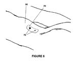
図5は、その曲率が患者50の背中の曲率と実質的に一致するように曲げられるフレームのような形状の支持構造78を備える、キャリブレーションファントム48の好適な実施態様を例示している。その外部形状に適合させるために、その原理を体の如何なる解剖学的部分にも展開し得る。この場合、上述の取付具を省略してよい。放射線不透過性マーカ80が支持構造78に取り付けられる。このファントム設計の利点は、ROI自体を自由に維持しながら、関心の領域(ROI)が放射線不透過性マーカによって取り囲まれ、それにより、走査中にROIに近接し且つ撮像されるマーカの数を最大限化しながら、外科医によるROIへの妨げられない外科的アクセスを可能にするという事実である。
FIG. 5 illustrates a preferred embodiment of a
理論的には、少なくとも2つの画像中で検出可能な1つだけのマーカを備えるファントムは、結果として得られる3D再構築の品質を既に増大させ得るが、より多くのファントムマーカを用いることは、キャリブレーションの精度を増大させ、それにより、再構築3D容積の品質を増大させる。 In theory, phantoms with only one marker detectable in at least two images may already increase the quality of the resulting 3D reconstruction, but using more phantom markers does not Increase the accuracy of the calibration, thereby increasing the quality of the reconstructed 3D volume.
他方、2DのX線画像中の相互のマーカの重なり合いの可能性が同時に増大させられる。 On the other hand, the possibility of mutual marker overlap in the 2D x-ray image is simultaneously increased.
完全に又は部分的に重なり合うカーマ陰影は、それらを識別し且つそれらの位置を正確に検出するのをより困難にし、或いは不可能にさせするので、それらの有用な数は限定される。 The useful numbers of kerma shadows that completely or partially overlap make them more difficult or impossible to identify and make their positions more accurately detected.
好適な実施態様において、取得される画像の少なくとも半分は、少なくとも5つの検出可能なマーカを含み、少ない割合の画像は非参照画像(non-reference images)である。図3に示すような典型的なファントム設計において、マーカ64の合理的な数は、5〜15の間である。それらは、軸65に沿う座標が各マーカについて異なるように、支持構造66上に配置される。典型的な軌道走査動作について、ファントムは、軸65が撮像システム20の軌道回転軸と本質的に平行であるように、位置付けられる。両方の軸が完全に平行でないとしても、マーカ陰影の重なり合いを回避し得る。
In a preferred embodiment, at least half of the acquired images contain at least five detectable markers, and a small proportion of the images are non-reference images. In a typical phantom design as shown in FIG. 3, a reasonable number of
3D走査の間、2DX線画像のセットが患者50に対する撮像システム20の異なる所定の位置で撮られる。
During 3D scanning, a set of 2D x-ray images are taken at different predetermined locations of
1つの好適な実施態様において、走査中の撮像システム20の動作は、ローラ30を用いたフロア移動を含む全ての他の自由度が係止(ロック)された、モータ駆動される純粋な軌道回転であるのに対し、所定の位置は、位置エンコーダで測定される等距離の軌道関節位置に対応する。
In one preferred embodiment, the motion of the
しかしながら、本発明の範囲はこの走査動作に限定されず、多次元走査動作及び非等距離走査位置について同様に作動することを印すのは重要である。 However, it is important to note that the scope of the present invention is not limited to this scanning operation, but works similarly for multi-dimensional scanning operations and non-equidistant scanning positions.
撮像システム20の全ての関節についての一連の位置エンコーダ値(位置エンコーダ値のセット)に対応する各所定の位置について、X線源22の焦点の位置並びに画像検出器24の位置及び向きは、臨床的使用の前にシャーシ28(図1bを参照)にリンクされる座標系29において決定され、ルックアップ表(LUT)内に格納される。
For each predetermined position corresponding to a series of position encoder values (a set of position encoder values) for all joints of the
公称投影データをもたらす、即ち、画像取得中に実際の幾何からの撮像システムの初期設定される投影幾何学データの変更を考慮に入れずに、設計、度量衡又はオフラインキャリブレーションによって知られ、且つ、材料疲労、機械的変形、振動、機械的遊び等によって引き起こされる、撮像システムの初期設定される投影幾何を記述するデータをもたらす、これらのデータを、異なる方法において集め得る。 To obtain nominal projection data, ie known by design, metrology or off-line calibration, without taking into account changes in the imaging system's initialized projection geometry data from the actual geometry during image acquisition and These data can be collected in different ways, resulting in data describing the initial projection geometry of the imaging system caused by material fatigue, mechanical deformation, vibration, mechanical play, etc.
1つの好適な実施態様において、これらの公称投影幾何学データは、最新技術において知られるように、オフラインキャリブレーションファントムを備えるCアームの臨床的な使用に先立って決定される。 In one preferred embodiment, these nominal projection geometry data are determined prior to clinical use of a C-arm equipped with an off-line calibration phantom, as is known in the state of the art.
そのようなキャリブレーション方法を用いることは、設計によって知られるに過ぎない値に対するX線源22及び画像検出器24の再現可能な位置偏差を考慮に入れるという利点を有する。
Using such a calibration method has the advantage of taking into account reproducible positional deviations of the
記載されるように、本発明はマーカを用いて有利に実施される。 As described, the invention is advantageously implemented using a marker.
そのため、放射線不透過性マーカを含むキャリブレーションファントムが用いられる。そのような実施態様において、3D画像を生成することは、以下のステップを含む。
a)本発明によって取り扱われることを意図しない初期的なステップにおいて、放射線不透過性マーカがROI、即ち、その3D画像が再構築されるべき解剖学的領域に近接するように、キャリブレーションファントム48を患者に取り付ける。
Therefore, a calibration phantom including a radiopaque marker is used. In such an embodiment, generating the 3D image includes the following steps.
a) In an initial step not intended to be handled by the present invention, the
少なくとも2つの2DのX線画像が、少なくとも1つの検出可能な放射線不透過性マーカを含まなければならないが、典型的には、2つよりも多くの画像は、1つよりも多くのマーカを含む。 At least two 2D x-ray images must contain at least one detectable radiopaque marker, but typically more than two images contain more than one marker. Including.
しかしながら、各々が1つだけの検出可能なマーカを含む、2つだけの画像の場合、前記画像は、キャリブレーションによって3D再構築を向上させるために、第1の画像に対する第2の画像の十分な投影に関する面外情報(projective out-of-plane information)をもたらすよう、互いに対して十分に角度付けられなければならない。実際には、2つの画像の間の角度は、少なくとも15°でなければならない。 However, in the case of only two images, each containing only one detectable marker, said images are sufficient for the second image relative to the first to improve the 3D reconstruction by calibration. Must be sufficiently angled with respect to each other to provide projective out-of-plane information. In practice, the angle between the two images should be at least 15 °.
次に、撮像システム20は位置付けられ、その関節は、撮像システムと患者、ファントム、患者テーブル、又はその近傍に存在するあらゆる他の物理的な物体との間の如何なる衝突もなく、走査のために必要とされるROIの周りの軌道回転動作を実施し得るように、調節される。軌道回転動作をCアームの複雑な軌道と置換し得ることに留意のこと。
The
b)次に、撮像システム20の軌道回転中に、前記所定の位置で、X線投影(2D)画像のセットを取得する。前記画像のセットは、データ処理ユニットのメモリ内に格納されてよい。
b) Next, during orbit rotation of the
c)次のステップにおいて、その物体に属する(それらのグレーレベル値によって重み付けられた)全ての画素(又は単に固定値に割り当てられる閾値よりも上の画素)を用いるグレーレベルにおいて物体の中心の座標を計算(calculate)する標準的な画像処理技法を用いて、データ処理ユニットによる対応するファントムマーカの自動識別を可能にするマーカ陰影を求めて、全ての2D画像を探索(サーチ)する。例えば、ボール形状のマーカについて、データ処理ユニットは、閉塞輪郭についての画像を確認し、識別される閉塞輪郭の真円度及び大きさを評価する。更なる詳細は、例えば、特許文献8及び特許文献2中に見出され得る。シリンダ又はチューブから成るマーカの投影に対応する線又は曲線の中心(即ち、前記線又は曲線の中央)を検出するために、類似の技法が用いられる。マーカを構成する送信器又は電磁センサのコイルの縁(エッジ)を検出するために、周知の技法が用いられる。 c) in the next step, the coordinates of the center of the object at the gray level using all pixels belonging to the object (weighted by their gray level values) (or pixels above the threshold simply assigned to fixed values) All 2D images are searched for marker shadows that allow automatic identification of the corresponding phantom markers by the data processing unit using standard image processing techniques that calculate. For example, for a ball shaped marker, the data processing unit verifies the image for the occlusion contour and evaluates the roundness and size of the occlusion contour identified. Further details can be found, for example, in US Pat. Similar techniques are used to detect the center of a line or curve (i.e., the center of the line or curve) corresponding to the projection of a marker consisting of a cylinder or tube. Well known techniques are used to detect the edges of the transmitter or coils of the electromagnetic sensor that make up the marker.
2D画像中の識別されるマーカ陰影の正確な位置の計算(calculation)は、例えば、非特許文献14及び非特許文献15に記載されるように、その中心を演算することによってデータ処理ユニットによって実施される。 The calculation of the exact position of the identified marker shadow in the 2D image is performed by the data processing unit by calculating its center, as described for example in [14] and [15]. Be done.
マーカの少なくとも1つを自動的に検出し得る、即ち、ファントムマーカの少なくとも1つについて、画像中の一連の画素をそれに割り当て得る、そして、その位置を決定し得る、画像を、参照画像(reference images)と呼ぶ。 At least one of the markers can be detected automatically, ie for at least one of the phantom markers, a series of pixels in the image can be assigned to it, and its position can be determined, the image being a reference image (reference Call it images).
残余の画像、即ち、マーカを自動的に検出し得ない画像を、非参照画像(non-reference images)と呼ぶ。正に、幾つかの理由のために、取得される一連の画像の全てにおいて、全てのマーカが実際に識別可能であるとは限らず、よって、全ての投影画像が、参照画像であるとは限らない。この現象を考慮に入れることは、本発明の基礎である。 The residual image, ie the image for which the marker can not be detected automatically, is called a non-reference image. Indeed, not all markers may actually be distinguishable in all of the acquired series of images for several reasons, so all projected images are reference images. Not exclusively. It is the basis of the present invention to take this phenomenon into account.
第1に、1つ又はそれよりも多くのマーカは、1つの、より多くの、又は全ての投影画像について、完全に又は部分的に検出器の視野の外側にあることがある。 First, one or more markers may be completely or partially outside the field of view of the detector, for one, more or all of the projected images.
第2に、マーカのうちの1つ又はそれよりも多くは、投影画像の1つ又は幾つかにおいて相互に重なりあることがある。 Second, one or more of the markers may overlap each other in one or more of the projected images.
第3に、1つ又はそれよりも多くのマーカは、金属外科器具、手術台、骨のような患者濃密構造(patient dense structures)等のような、投影画像のうちの1つ又はそれよりも多くにおいて、他の放射線濃度の高い物体と重なり合うことがある。造影剤の使用は、この困難を強化する。 Third, one or more of the markers may be one or more of the projected images, such as metal surgical instruments, an operating table, patient dense structures such as bones, etc. In many cases, it may overlap with other high radiation density objects. The use of contrast agents reinforces this difficulty.
第4に、1つ又はそれよりも多くのマーカは、X線によって過剰被爆された又はぼかされた(blurred)或いは低い信号対雑音比を備える画像領域であることがあり、それはそれらを検出不能にする。 Fourth, one or more markers may be image areas with signal-to-noise ratio over-exposed or blurred or low by X-rays, which detect them Disable.
各参照画像について、その画像中の各々の識別されるマーカの2D位置は、上述の画像処理技法を用いて計算される。 For each reference image, the 2D position of each identified marker in that image is calculated using the image processing techniques described above.
次のステップでは、座標系29及び49の間の最適な等長変換(rigid transformation)を演算する。
The next step is to compute the optimal rigid transformation between coordinate
本発明の1つの実施態様において、この最適な変換は、29及び49の間の標準的な6つの変換パラメータを調節することによって、この画像のそれぞれの公称投影幾何学データ及びキャリブレーションファントムの座標系における対応するファントムマーカの既知の3D位置を用いて、各参照画像中の前記検出されるマーカの2D位置から計算される背面投影線の間の全ての検出されるマーカについての距離の二乗の合計を最小限化する、特徴ベース2D/3D再構築技法を用いて演算される。2つの別個の座標系において既知の3D線と3D地点との間の距離の二乗の合計のそのような最小限化は、非特許文献16において公表されているIterative Closest Pointアルゴリズム又はその変形のいずれか、例えば、Levenberg-Marquardtアルゴリズムを用いて達成され得る。アウトライアー(outliers)を排除する任意の周知の確固たるアルゴリズムを用いて、この方法の信頼性を向上させ得る。 In one embodiment of the present invention, this optimal transformation is adjusted by adjusting the standard six transformation parameters between 29 and 49, the respective nominal projection geometry data of this image and the coordinates of the calibration phantom. The square of the distance for all detected markers between the back projection lines calculated from the 2D positions of said detected markers in each reference image, using the known 3D positions of the corresponding phantom markers in the system It is computed using feature-based 2D / 3D reconstruction techniques that minimize the sum. Such minimization of the sum of squares of distances between known 3D lines and 3D points in two separate coordinate systems can be done either by using the Iterative Closest Point algorithm published in [16] or any of its variants. Or, for example, it can be achieved using the Levenberg-Marquardt algorithm. The reliability of the method can be improved using any well-established robust algorithm that eliminates outliers.
本発明の他の実施態様において、この最適な変換は、各参照画像中の前記検出されるマーカの2D位置と、29及び49の間の6つの変換パラメータを調節することによってこの画像のそれぞれの公称投影幾何学データから計算される前記参照画像上のそれぞれのマーカの3D位置の投影の位置との間の、全ての検出されるマーカについての距離を最小限化することによって演算される。アウトライアーを排除する如何なる周知の確固たるアルゴリズムを用いて、この方法の信頼性を向上させ得る。 In another embodiment of the invention, the optimal transformation is performed by adjusting the 2D position of the detected marker in each reference image and six transformation parameters between 29 and 49 in each of the images. It is calculated by minimizing the distance for all detected markers between the position of the projection of the 3D position of the respective marker on the reference image which is calculated from the nominal projection geometry data. The reliability of this method can be improved using any known robust algorithm that eliminates outliers.
1つの実施態様において、キャリブレーションファントムは、信号マーカのみを含む。この場合、29及び49の間の変換は平行移動(translation)のみを含み、次に、回転値はゼロ初期設定値に割り当てられる。 In one embodiment, the calibration phantom contains only signal markers. In this case, the conversion between 29 and 49 involves only translation, and then the rotation value is assigned to the zero initialization value.
1つの実施態様において、キャリブレーションファントムは2つのマーカのみを含む。この場合、29及び49の間の変換は平行移動及び2つの自由度の周りの回転を含み、1つの軸の周りの回転は決定されず、ゼロ初期設定値に割り当てられる。 In one embodiment, the calibration phantom contains only two markers. In this case, the transformation between 29 and 49 involves a translation and a rotation around two degrees of freedom, the rotation around one axis is not determined and is assigned to a zero initialization.
参照画像を、自動的に検出し得るファントムマーカの少なくとも所与の数のNBを含む画像として定めることができ、NB>0である。NBが高ければ高いほど、更に記載する公称投影幾何学データに適用される調節はより正確であるが、参照画像の数はより少ない。数NBを選択することは、本発明の使用の具体的な脈絡に依存する。幾つかの場合において、各画像中で通常検出される放射線不透過性マーカの数は、極めて高くあり得る。従って、キャリブレーションファントムを構成するマーカの総数に近いNBの値を選択することが推奨される。例えば、キャリブレーションファントムが8つの放射線不透過性ボールから成るならば、7の値にNBを割り当てる。より複雑な場合には、各画像中で通常検出される放射線不透過性マーカの数は、極めて低くあり得る。従って、1又は2であるNBの値を選択することが推奨される。 The reference image can be defined as an image comprising at least a given number NB of phantom markers that can be detected automatically, wherein NB> 0. The higher the NB, the more accurate the adjustments applied to the nominal projection geometry data described further, but the fewer the number of reference images. The choice of the number NB depends on the specific context of the use of the invention. In some cases, the number of radiopaque markers normally detected in each image can be quite high. Therefore, it is recommended to select an NB value close to the total number of markers that make up the calibration phantom. For example, if the calibration phantom consists of eight radiopaque balls, assign an NB to the value of seven. In more complex cases, the number of radiopaque markers normally detected in each image may be quite low. Therefore, it is recommended to select the value of NB which is 1 or 2.
好適な実施態様において、非参照画像に対する参照画像を定めるマーカの数NBは、本発明の包括的方法の第1の反復について1のような低い値が割り当てられることができ、次に、包括的方法は繰り返されることができるが、数NBはより高い値に増大させられる。このプロセスを繰り返し、数回反復し得る。 In a preferred embodiment, the number NB of markers defining the reference image relative to the non-reference image can be assigned a low value such as 1 for the first iteration of the inventive generic method, and then generically The method can be repeated but the number NB is increased to higher values. This process may be repeated and repeated several times.
d)次のステップでは、画像上に投影されるときに、その関連する2Dマーカ陰影位置が変換3Dファントムマーカ位置の2D位置と最適に一致するように、各参照画像についての公称投影幾何学データを調節する。 d) In the next step, nominal projection geometry data for each reference image, such that when projected onto the image, its associated 2D marker shadow position optimally matches the 2D position of the transformed 3D phantom marker position Adjust the
1つの実施態様において、各参照画像のために公称投影幾何学データに適用される調節は、画像検出器と平行な平面内のX線源の2つの座標に限定される。これは各2D画像のために2つの独立したパラメータを探究することを含む。他の実施態様において、公称投影幾何学データの調節は、X線源の3つの座標、及び行列又は6つの独立した回転/平行移動パラメータによって提示される画像検出器の完全な位置及び向き、並びに画素対ミリメートル比(画像検出器についての先験的情報(アプリオリ情報)に依存して1つ又は2つの比)を決定する画像中のスケーリング因子を含む。これは各2D画像について10の又は11の独立したパラメータを探究することを含む。 In one embodiment, the adjustments applied to nominal projection geometry data for each reference image are limited to the two coordinates of the x-ray source in a plane parallel to the image detector. This involves exploring two independent parameters for each 2D image. In another embodiment, the adjustment of the nominal projection geometry data comprises three coordinates of the X-ray source, and the complete position and orientation of the image detector presented by the matrix or six independent rotation / translation parameters, and It contains scaling factors in the image that determine the pixel to millimeter ratio (one or two ratios depending on the a priori information about the image detector). This involves exploring 10 or 11 independent parameters for each 2D image.
他の実施態様では、2〜11に亘って、各画像についてパラメータの中間数が調節される。 In another embodiment, the median number of parameters is adjusted for each image across 2-11.
このようにして、投影幾何は、公称投影幾何学データによって取り扱われないX線源22及び検出器24の再現不能な位置偏差を補償するために、発明的に補正される。
In this way, the projection geometry is inventively corrected to compensate for non-reproducible position deviations of the
本発明において、我々は、如何なる幾何学的な画像歪みを回避するという従来的な画像増強装置(image intensifier)に対する利点を有する、完全デジタルフラットパネル画像検出器の使用を推奨する。しかしながら、従来的な画像増強装置が用いられるならば、公称投影幾何学データにおいて、歪み補償モデルを考慮することが必要であることがあり、それは、通常、画素画像座標とミリメートルで表現される画像平面内の座標との間の多項式関数である。後者の場合、公称投影幾何学データ幾何の調節は、対応する多項式関数の係数の調節を含まなければならないが、これは多くのマーカを使用することを必要とする。従って、実際には、多項式関数の調節を無視し、前述したような等長変換に対応するパラメータのみを調節する。しかしながら、その場合には、Cアームの向きで異なる係数を備える多項式関数を計算し且つ公称パラメータ内に格納するのが好ましい。何故ならば、歪みはCアーム向きで相当に異なることが知られているからである(これは磁場の影響及びCアームの機械的変形に起因する)。これは、最適には磁場の向きを検出する磁気計を考慮に入れて、Cアーム検出器に固定される剛的な平面格子を用いてCアームの様々な向きについて多項式関数を較正することによって、オフラインキャリブレーション中に簡単に達成される。その場合、本発明の方法を用いて各オンライン画像についてのモデルの11又は12のパラメータを最適化することは、公称パラメータに対する歪みの変動のある程度の量を部分的に補償する。他の解決策は、オンラインの各画像について多項式関数を計算するために、多数のマーカを備える平面格子をCアーム上に恒久的に固定して、ファントムマーカと別個にそれらのマーカを検出することである。 In the present invention, we recommend the use of a fully digital flat panel image detector which has the advantage over conventional image intensifiers to avoid any geometrical image distortion. However, if a conventional image intensifier is used, it may be necessary to consider a distortion compensation model in the nominal projection geometry data, which is usually an image expressed in pixel image coordinates and millimeters. It is a polynomial function between coordinates in the plane. In the latter case, the adjustment of the nominal projection geometry data geometry must involve the adjustment of the coefficients of the corresponding polynomial function, which requires the use of many markers. Therefore, in practice, the adjustment of the polynomial function is ignored, and only the parameters corresponding to the isometric transformation as described above are adjusted. However, in that case, it is preferable to calculate a polynomial function with different coefficients in the orientation of the C-arm and store it within the nominal parameters. This is because the strain is known to be quite different in the C-arm orientation (this is due to the effect of the magnetic field and the mechanical deformation of the C-arm). This is by calibrating the polynomial function for different orientations of the C-arm using a rigid planar grid fixed to the C-arm detector, optimally taking into account the magnetometer detecting the orientation of the magnetic field , Easily achieved during off-line calibration. In that case, optimizing the 11 or 12 parameters of the model for each on-line image using the method of the present invention partially compensates for some amount of distortion variation relative to the nominal parameters. Another solution is to fix a planar grid with a large number of markers permanently on the C-arm to detect those markers separately from the phantom markers, in order to calculate the polynomial function for each image online It is.
e)Filtered Back Projection又はAlgebraic Reconstruction Techniquesのような、当該技術分野において既知の標準的な断層撮影再構築技術を用いて、座標系29内で第1の3D画像を今や演算し得る。
e) A first 3D image can now be computed in coordinate
取得した一連の画像のうちのどの投影画像が3D画像のこの第1の再構築のために用いられるかを決定するために、再構築性基準が用いられる。 A reconstruction criterion is used to determine which projection image of the acquired series of images is to be used for this first reconstruction of the 3D image.
再構築性基準は経験的に決定され、参照画像の数及び角分布に依存する。 The reconstruction criteria are determined empirically and depend on the number and angular distribution of reference images.
再構築性基準は、以下の事項を含む試験として定められ得る。
− 十分な参照画像があるか?
− 参照画像の角範囲(angular coverage)は十分であるか?
− 参照画像の角分布は十分に均一であるか?
The rebuildability criteria can be defined as a test including the following items.
-Do you have enough reference images?
-Is the angular coverage of the reference image sufficient?
-Is the angular distribution of the reference image sufficiently uniform?
基準を満足する(即ち、上記事項の各々に対する応答が「はい」である)ならば、3D画像の初期再構築のために、それらの対応する調節された投影幾何学データを備える参照画像のみが用いられる。 If the criteria are satisfied (i.e. the response to each of the above is "yes") then only the reference images with their corresponding adjusted projection geometry data for initial reconstruction of the 3D image Used.
他方、基準を満足しない(即ち、上記事項のうちの少なくとも1つに対する応答が「いいえ」である)ならば、参照画像のみに基づく再構築は良好な結果をもたらさない。例えば、参照画像が全て90度以下の角範囲(angular range)の内側で得られるならば、再構築プロセスは不充分な品質の3D画像をもたらすことが知られている。好適な実施態様では、十分な品質の初期3D画像をもたらすために、再構築は、それらの対応する調整された投影幾何学データを備える参照画像のみならず、それらの対応する公称投影幾何学データを備える参照画像も用いることによって、実施される。 On the other hand, if the criteria are not met (i.e., the response to at least one of the above is "No"), reconstruction based on the reference image alone will not yield good results. For example, if the reference images are all obtained inside an angular range of 90 degrees or less, it is known that the reconstruction process results in 3D images of poor quality. In a preferred embodiment, the reconstruction is not only reference images with their corresponding adjusted projection geometry data, but also their corresponding nominal projection geometry data, in order to give an initial 3D image of sufficient quality. Is also implemented by using a reference image comprising
他の好適な実施態様において、非参照画像の投影幾何学データは調節され、前記非参照画像を取り囲む参照画像の投影幾何学データの補間によって演算される。次に、全ての調節された投影幾何学データを用いて、3D再構築が行われる。 In another preferred embodiment, projection geometry data of the non-reference image is adjusted and calculated by interpolation of projection geometry data of the reference image surrounding the non-reference image. Next, 3D reconstruction is performed using all the adjusted projection geometry data.
他の好適な実施態様において、再構築は、それらの公称投影幾何学データを用いて、全ての画像を用いて達成される。 In another preferred embodiment, reconstruction is achieved using all the images, using their nominal projection geometry data.
所望の精度、再構築性基準、及び選択される実施態様に依存して、そのステップの終わりに方法を停止することが可能である。しかしながら、本発明の方法は、追加的なステップを行って、再構築3D画像の精度及び品質を増大させることを提案する。 It is possible to stop the method at the end of that step, depending on the desired accuracy, the revisability criteria and the embodiment chosen. However, the method of the invention proposes to perform an additional step to increase the accuracy and quality of the reconstructed 3D image.
f)次のステップでは、3D画像が参照画像だけで再構築されようがされまいが、前記3D画像を、それらのそれぞれの公称投影幾何学データを用いて、各非参照画像の上に投影する。 f) In the next step, although the 3D image is not to be reconstructed only with the reference image, the 3D images are projected onto each non-reference image using their respective nominal projection geometry data .
引き続き、前記非参照画像の前記公称投影幾何学データを調節するために、相互情報、結合エントロピー、又は相互相関比のような、周知の画像類似性測定を用いる、2D−2Dグレーレベル/強さに基づく位置合わせ技法が、各非参照画像及びそのそれぞれの投影3D画像に適用される。例えば、被特許文献16又は非特許文献17に記載される数多くの2D−2D位置合わせ方法のうちの1つを適用し得る。 2D-2D gray levels / intensity using known image similarity measures, such as mutual information, joint entropy, or cross correlation ratio, to subsequently adjust the nominal projection geometry data of the non-reference image A registration technique based on is applied to each non-reference image and its respective projected 3D image. For example, one of the many 2D-2D alignment methods described in US Pat.
本発明の1つの実施態様において、各非参照画像に関連付けられる投影幾何学データに対する調節は、画像検出器の回転及び平面内変換に限定され、それは各2D−2D画像位置合わせのために3つの独立したパラメータを見出すことに対応する。 In one embodiment of the present invention, adjustments to projection geometry data associated with each non-reference image are limited to image detector rotation and in-plane transformation, which are three for each 2D-2D image registration. It corresponds to finding independent parameters.
他の実施態様では、平行移動パラメータのみが調節され、それは間違った調節の危険性を減少させる。 In another embodiment, only translation parameters are adjusted, which reduces the risk of false adjustment.
他の実施態様では、3つよりも多くの独立したパラメータを含む2D−2D変換、例えば、画像の4つの隅を独立して変位させるワーピング変換(warping transform)又は疑似変換(affine transform)が定められる。 In other embodiments, a 2D-2D transform including more than three independent parameters, eg, a warping transform or affine transform, which displaces four corners of the image independently is defined. Be
g)次に、対応する調節された投影幾何学データで備える完全な一連の2D画像(2D画像のセット)を用いて、更新されたより正確な3D画像を演算する。 g) Next, compute the updated more accurate 3D image using the complete series of 2D images (set of 2D images) comprising the corresponding adjusted projection geometry data.
本発明の1つの実施態様において、上述の方法の1つ又は幾つかのステップは、位置合わせ品質測定値が所定の閾値より下になるまで(例えば、品質測定値は3D画像のコントラスト(contrast)又は鮮明さ(sharpness)であり得る)或いは所定の数の反復(例えば、1回の反復又は3回の反復)に達するまで繰り返される。 In one embodiment of the invention, one or several steps of the method described above are carried out until the alignment quality measurement falls below a predetermined threshold (e.g. the quality measurement is a contrast of the 3D image) Or may be sharpened) or repeated until a predetermined number of iterations (eg, one or three iterations) is reached.
1つの実施態様では、調節された投影幾何学データ及び/又はマーカの再構築3D位置を用いて、画像中の前記マーカの理論的な位置の推定を用いて放射線不透過性マーカの探索及び検出を繰り返し、次の探索を開始し得る。それは、包括的方法の次の反復のために、検出されるマーカの数を増大させるという利点を有し、従って、再構築される画像の精度を向上させる可能性が高い。この機構によって、非参照画像に対する参照画像を定めるマーカの最小数NBを、反復毎に進行的に増大させ得る。 In one embodiment, with the aid of adjusted projection geometry data and / or the reconstruction 3D position of the markers, the search and detection of radiopaque markers using an estimation of the theoretical position of said markers in the image Can be repeated to start the next search. It has the advantage of increasing the number of markers detected for the next iteration of the generic method, and thus is likely to improve the accuracy of the reconstructed image. By this mechanism, the minimum number NB of markers that define the reference image relative to the non-reference image can be progressively increased with each iteration.
他の実施態様では、最終的な再構築3D画像の品質を向上させるために、ステップ(f)及び(g)のみが繰り返される。 In another embodiment, only steps (f) and (g) are repeated to improve the quality of the final reconstructed 3D image.
次に、視覚化するために、再構築3D画像をグラフィックディスプレイに送信し得る。 The reconstructed 3D image may then be sent to a graphic display for visualization.
更なる使用のために、再構築3D画像をデータ処理ユニットのメモリ内に格納することもできる。 The reconstructed 3D image can also be stored in the memory of the data processing unit for further use.
キャリブレーションファントムが、ナビゲーションシステム(例えば、電磁センサ又は送信器又は光学トラッカー(optical tracker))によって検出される局所化装置を含むならば、結果として得られる3D画像は直接的に移転され、3D画像の内側で器具のナビゲーションのために用いられる。 If the calibration phantom includes a localization device detected by a navigation system (eg, an electromagnetic sensor or transmitter or an optical tracker), the resulting 3D image is directly transferred, and the 3D image is transferred. Used for navigation of the instrument inside the
本発明の実施態様のいずれにおいても、更なる使用のために以前の公称投影幾何学データを更新するために、3D再構築の終わりに得られる計算される調節される投影幾何学データを格納し得る。更なる使用は同じ患者について同じ日に起こり得るし、或いは別の患者について数日後に起こり得る。その場合には、投影幾何学データの進化を追跡することが可能であり、それは装置の保守についての有用な表示をもたらす。例えば、投影幾何学データの突然の相当な変化は、おそらく、装置の更なる検査を必要とする衝撃又は機械的変更に対応する。 In any of the embodiments of the present invention, store the computed adjusted projection geometry data obtained at the end of the 3D reconstruction to update previous nominal projection geometry data for further use obtain. Further use may occur on the same day for the same patient, or several days later for another patient. In that case, it is possible to track the evolution of projection geometry data, which provides a useful indication of the maintenance of the device. For example, a sudden and significant change in projection geometry data probably corresponds to an impact or mechanical change requiring further inspection of the device.
好適な実施態様の方法を例示するために、本方法は1つだけのマーカから成るファントムについて記載された。この実施例において、マーカは、直径4ミリメートルのステンレス鋼の球形ボールである(図7を参照)。マーカ72は、心電図皮膚電極についてのように接着テープを用いることによって、撮像されるべき領域において患者50の皮膚に単に固定される。この実施例では、皮膚は関心の解剖学的構造に対して有意に移動しないことが想定される。Cアームの軌道回転の1度毎に、一連の190の画像が取得される。フラットパネル画像検出器が用いられる。各画像はコンピュータによって解析され、金属ボールが探索される。しかしながら、ある領域における過剰被爆のような、様々な現象の故に、ボールが全ての画像上で自動的に正確に検出されない可能性が高い。この実施例では、ボールは30度の角度区画に関する画像(非参照画像)中に検出されず、全ての他の画像(参照画像)中で自動的に検出されることが想定される。再構築性基準を満足することが想定される。参照画像の公称投影幾何を用いるならば、球形ボールの投影の中心が3Dにおいて逆投影される(back projected)。逆投影線の交点は、3D球形ボールの中心として定められる3D地点を定める。X線撮像システムの座標系とキャリブレーションファントムの座標系との間の最適な等長変換が、3D球形ボールの計算される中心をX線撮像システム座標の原点と位置合わせする平行移動と、単位行列(identity matrix)と等しい回転成分とによって簡単に定められる。次に、前記3D球形ボールは各画像の上に投影され、平行移動が各画像に適用されて、前記3D球形ボールの投影を画像上のボール中心の真正な位置と一致させる。従って、参照画像の公称投影幾何学データは、画像平面内の平行移動によって調節される。次に、それらの調節された投影幾何学データを備える参照画像のみを用いて、第1の3D画像再構築が行われる。次に、結果として得られる3D画像は、全ての非参照画像の上に投影され、2D−2D画像位置合わせが、それらの非参照画像だけについて、3D画像の投影画像と実画像との間で行われる。それは各画像の平行移動及び回転を生み、それは投影幾何学データの3つの調節されたパラメータに対応する。プロセスを加速させるために、位置合わせは各々の実画像の中心領域を考慮することだけによって行われる。位置合わせが画像間位置合わせ技法の従来的な基準によって与えられる低い位置合わせスコアによって与えられる不確かな結果をもたらすならば、位置合わせは無視され、公称投影幾何学データが考慮に入れられる。このステップの結果は、全ての画像についての新しい一連の調節された投影幾何学データである。次に、全ての画像に適用される前記調節された投影幾何学データを用いて、第2の3D再構築が行われる。この第2の投影幾何学データは、公称投影幾何学データを用いて行われた再構築よりも良好な精度及び品質を有する。
To illustrate the method of the preferred embodiment, the method has been described for a phantom consisting of only one marker. In this example, the marker is a 4 mm diameter stainless steel spherical ball (see FIG. 7). The
他の実施例において、キャリブレーションファントムは、2つの球形マーカから成る(図6を参照)。2つのボール72は患者50の体と平行な方向に配置され、接着テープ70を用いて取り付けられ、体の周りで画像取得が行われる。それは両方のボールの投影が互いに重なり合わないという利点を有し、それは1つのボールだけを用いるよりも多くの精度を生む。前述と同じ方法が適用され、唯一の相違は、(a)一定の相対的な幾何学的構成を備える2つのボールの探究が1つだけのボールよりも確実であること、並びに、(b)第1のステップにおいて得られる調節される投影幾何学データが、平行移動だけでなく、画像の回転及び平行移動に対応することである。平行移動のみを維持して、少なくとも二乗技法を用いることによってボールのより正確な位置合わせを得ることも可能である。図6に例示するように、2つのボールが異なる直径を有するのが有利である。
In another embodiment, the calibration phantom consists of two spherical markers (see FIG. 6). The two
第3の実施例において、キャリブレーションファントムは、4つのボールと、6つのピンとから成る。6つのピンは、椎骨の各側に3つのピンの経皮的なピン固定を用いて、キャリブレーションファントムを椎骨に剛的に取り付けるために用いられる。4つのボールは反射性材料で覆われ、それらは光学ローカライザによって検出される剛性体を構成する。この剛性体は患者参照システムを構成する。ボール及びピンの座標は、患者参照システムと同じ特異なキャリブレーションファントム座標系において全て知られている。一連の190の画像がCアームの軌道回転の1度毎に取得される。各画像はコンピュータによって解析され、金属ボール及びピンが探索される。幾つかの画像において、少なくとも3つのボールが検出され、自動的に標識付けされる。それらは参照画像を構成する。他の画像は非参照画像を構成する。全ての参照画像について、検出されるボール及びピンセグメントは、公称投影幾何学データを用いて逆投影される。各画像について、前記逆投影は、キャリブレーションファントム座標系内に表されるボール及びピンの3D座標と位置合わせされる。それはキャリブレーションファントム座標系と公称投影幾何学データを定めたCアームの座標系との間の変換行列を生成する。各画像について、3Dボール及びピンは画像の上に投影され、投影幾何学データは、ボール及びピンの理論的な投影と画像上のそれらの実際の抽出(extraction)との間の距離の二乗の合計を最小限化させる最小二乗基準を用いて、それらを一致させるように調節される。この実施例では、X線源及び画像源(image origin)の両方は等しく平行移動させられ、加えて、画像平面の回転が調節される。次に、手順の残余は、前の実施例と等しい。しかしながら、その場合には、反射性球体を備える外科器具をナビゲートして、結果として得られる3D画像の上にその位置を実時間で視覚化することが可能である。何故ならば、画像は、それ自体が直接的に患者参照システムの座標系であるキャリブレーションファントムの座標系内で、直接的に再構築されるからである。 In a third embodiment, the calibration phantom consists of four balls and six pins. Six pins are used to rigidly attach the calibration phantom to the vertebrae, using three pin percutaneous pinning on each side of the vertebrae. The four balls are covered with a reflective material, which constitute a rigid body that is detected by the optical localizer. This rigid body constitutes a patient reference system. The ball and pin coordinates are all known in the same unique calibration phantom coordinate system as the patient reference system. A series of 190 images are acquired every degree of orbital rotation of the C-arm. Each image is analyzed by a computer to search for metal balls and pins. In some images, at least three balls are detected and automatically labeled. They constitute a reference image. Other images constitute non-reference images. For all reference images, detected ball and pin segments are backprojected using nominal projection geometry data. For each image, the backprojection is aligned with the ball and pin 3D coordinates represented in a calibration phantom coordinate system. It generates a transformation matrix between the calibration phantom coordinate system and the coordinate system of the C-arm which defined nominal projection geometry data. For each image, 3D balls and pins are projected onto the image, and projection geometry data is the square of the distance between the theoretical projection of the balls and pins and their actual extraction on the image. Adjust them to match, using a least squares criterion to minimize the sum. In this embodiment, both the x-ray source and the image origin are translated equally and, in addition, the rotation of the image plane is adjusted. The remainder of the procedure is then equal to the previous example. However, in that case it is possible to navigate the surgical instrument comprising the reflective sphere and visualize its position in real time on the resulting 3D image. The reason is that the image is directly reconstructed within the coordinate system of the calibration phantom, which itself is directly the coordinate system of the patient reference system.
第4の実施例において、画像の取得は、それらの場所を確認するために、茎ねじ(pedicle screw)のようなインプラントが患者の体内に挿入された直ぐ後に行われる。患者に取り付けられる追加的なマーカはない。キャリブレーションファントムは、部分的に既知の幾何学的構成を有するマーカを構築するインプラントで直接的に作製される。金属インプラントは画像上で特に良く見える。例えば、2つの椎骨が手術された後、4つの茎ねじが画像上で観察される。インプラントの個々の幾何学的構成は知られており、コンピュータ内に格納される。しかしながら、インプラント間の相対的な幾何は知られていないままである。第1のステップにおいて、インプラントを検出し且つ別個に識別し得る全ての画像が選択され、各インプラントの三次元位置及び向きは、3D/2D厳密位置合わせ(rigid registration)アルゴリズムを用いて、それらの画像上で検出される投影を用いて再構築される。キャリブレーションファントムは、今や完全に且つ全体的に知られる。次に、方法の残余が続く。この実施例におけるこの方法の利点は、高度の精密さ及び鮮明さを備える、インプラントを伴う骨の明瞭で精密な3D画像を得ることであり、それはインプラントをそれらの目下の位置のままにさせるか或いはそれらの一部で再手術するかの決定を容易にする。 In a fourth example, acquisition of images is performed shortly after an implant such as a pedicle screw is inserted into the patient's body to confirm their location. There are no additional markers attached to the patient. The calibration phantom is made directly with an implant that builds a marker with a partially known geometrical configuration. Metal implants look particularly good on the image. For example, after two vertebrae are operated on, four pedicle screws are observed on the image. The individual geometrical configurations of the implant are known and stored in a computer. However, the relative geometry between the implants remains unknown. In the first step, all images that can detect and separately identify the implants are selected, and the three-dimensional position and orientation of each implant is determined using the 3D / 2D rigid registration algorithm. It is reconstructed using the projections detected on the image. The calibration phantom is now completely and totally known. Then the rest of the method follows. The advantage of this method in this example is to obtain a clear and precise 3D image of the bone with the implant, with a high degree of precision and sharpness, does it leave the implants in their current position Or to facilitate the decision to re-operate on part of them.
本発明の他の実施態様によれば、一連の190の画像がCアームの軌道回転の1度毎に取得されるが、マーカは2D画像上で検出されない。これは患者が不充分な品質の画像を創り出す大きな体積のような特徴を有する故であることがある。これはキャリブレーションファントムが使用者によって忘れられるならば当て嵌まることもある。これは、キャリブレーションファントムが非侵襲的であり且つコンパクトであるとしても、使用者が単にキャリブレーションファントムを位置決める時間及び労力を取りたくない故に当て嵌まることもある。その実施例において、上述の方法の第1の部分は適用され得ない。何故ならば、マーカがないか或いは検出可能なマーカがないからである。その場合には、方法の第2の部分のみを適用することが可能である(そこでは、全ての画像が非参照画像である)。第1に、取得された全ての2D画像と関連付けられる公称投影幾何学データを用いて、3D画像が再構築される。第2に、再構築された3D画像は、公称投影幾何学データを依然として用いて、各2D画像の上に投影される。それは仮想のグレーレベル画像を構成する。この投影ステップは、例えば、プロセスを加速させるCuda言語におけるプログラミングを用いて、図形処理ユニット(GPU)の利益を享受し得る。各2D画像について、2D−2D画像位置合わせ方法が現実の2D画像と3D画像の投影との間に適用される。例えば、非特許文献17に記載される技法を用いて、両方の画像の相互の情報が所定の関心の領域内で最大限化されるように、例えば、1つの2D平行移動及び1つの回転(3つのパラメータ)から成る最適な等長変換が探索される。関心の領域を定めるために、可能な解決策は、第1の再構築3D画像中で、ノイズをフィルタリングした後に高コントラストを有する3D画素を探索して、そのような高コントラストの質量中心を特定し、そして、前記質量中心を2D画像の上に投影することであり、各次元における総画像サイズの半分のような先験的サイズを有する結果として得られる投影地点の周りの有界ボックス(bounding box)を備える(3D画像容積は8で除算される)。位置合わせのプロセスを加速させるために、例えば、ウェーブレット(wavelet)を用いて或いはピラミッド(pyramids)だけを用いて、従来的なマルチレベル位置合わせ技法を用い得る。各画像について、3つの調節されたパラメータが得られ、それらの調節された投影幾何学データを備える全ての画像を用いて、第2の3D再構築が行われる。用途によって要求される精度に依存して、必要であれば、方法を反復し得る。その場合、第2の3D再構築画像は全ての2D画像の上に投影され、2D−2D位置合わせが第2の3D再構築画像の投影と現実の画像との間で再び行われる。これは新しい一連の調節された投影幾何学データをもたらす。対応する調節された投影幾何学データを用いて、第3の再構築が行われる。要求される制度及び時間の制約に依存して、必要な回数だけ方法を反復し得る。一定の数の反復を事前設定し得るし、或いはコントラスト基準を再構築3D画像上で計算し得る。そして、前記基準が所与の閾値よりも上になるときに、プロセスは停止され、それは常に良好な鮮明さを有する3D画像を生成するという利点を有する。 According to another embodiment of the invention, a series of 190 images are acquired for each degree of C-arm trajectory rotation, but no markers are detected on the 2D image. This may be because the patient has large volume-like features that create poor quality images. This may be true if the calibration phantom is forgotten by the user. This may be true because even though the calibration phantom is non-invasive and compact, the user simply does not want to take the time and effort to position the calibration phantom. In that embodiment, the first part of the method described above can not be applied. This is because there is no marker or no detectable marker. In that case, it is possible to apply only the second part of the method (where all the images are non-reference images). First, a 3D image is reconstructed using nominal projection geometry data associated with all acquired 2D images. Second, the reconstructed 3D images are projected onto each 2D image, still using nominal projection geometry data. It constitutes a virtual gray level image. This projection step can benefit from the graphics processing unit (GPU), for example, using programming in the Cuda language to accelerate the process. For each 2D image, a 2D-2D image registration method is applied between the projection of the real 2D image and the 3D image. For example, one 2D translation and one rotation (for example, one 2D translation and one rotation (for example), so that mutual information of both images is maximized within a given region of interest, using the techniques described in An optimal isometric transformation consisting of three parameters is searched. In order to define a region of interest, a possible solution is to filter noise in the first reconstructed 3D image and then search for 3D pixels with high contrast to identify such high contrast mass centers And projecting the center of mass onto the 2D image, bounding around the resulting projection point having an a priori size such as half the total image size in each dimension box) (3D image volume is divided by 8). Conventional multi-level registration techniques may be used to accelerate the registration process, for example, using wavelets or only pyramids. For each image, three adjusted parameters are obtained and a second 3D reconstruction is performed using all the images comprising their adjusted projection geometry data. Depending on the accuracy required by the application, the method may be repeated if necessary. In that case, the second 3D reconstructed image is projected onto all 2D images, and 2D-2D registration is again performed between the projection of the second 3D reconstructed image and the real image. This results in a new set of adjusted projection geometry data. A third reconstruction is performed using the corresponding adjusted projection geometry data. Depending on the required system and time constraints, the method may be repeated as many times as necessary. A fixed number of iterations may be preset, or contrast references may be calculated on the reconstructed 3D image. Then, when the criterion goes above a given threshold, the process is stopped, which has the advantage of always producing a 3D image with good sharpness.
上述のように、マーカの使用を伴って或いは伴わないで本発明を実施し得る。マーカを用いることは方法の安定性及び精度を強化し、3D画像がナビゲーションのために用いられるならば、それはいずれにしても必要とされる。マーカを使用しないことが使用者にとってより簡単であるのはもちろんであるが、それは、方法の収束(convergence)が保証されるように、初期公称投影幾何学データが現実の投影幾何学データに合理的に近いことを要求する。結局、体のいずれかの部分のために、ナビゲーションへのリンクを備えて或いは備えないで、診断的撮像中に或いは手術中に、多様なX線システムアーキテクチャのために、多様な用途において、方法を用い得る。標準的なコンピュータ断層撮影の代わりに、X線フラットパネル検出器を含む装置を用いて物体の非破壊的な確認のような非医療用途のためにも、方法を用い得る。この発明において提案する方法は、各状況に従って調節される多数のパラメータ及びオプションを提供する。 As mentioned above, the invention may be practiced with or without the use of markers. Using a marker enhances the stability and accuracy of the method, which is required anyway if a 3D image is used for navigation. It is of course easier for the user not to use a marker, but it is reasonable for the initial nominal projection geometry data to be real projection geometry data so that the convergence of the method is guaranteed. Require closeness. Finally, for any part of the body, with or without a link to navigation, during diagnostic imaging or during surgery, for various X-ray system architectures, in various applications, methods Can be used. Instead of standard computed tomography, the method can also be used for non-medical applications such as nondestructive confirmation of objects using devices including X-ray flat panel detectors. The method proposed in the present invention provides a number of parameters and options that are adjusted according to each situation.
Claims (15)
前記X線撮像システムのプロセッサが、
a)2DX線画像のセットの取得中に患者内に又は患者上に配置されるキャリブレーションファントムの座標系において既知の3D位置を有する少なくとも1つの放射線不透過性マーカを含む前記キャリブレーションファントムを用いる前記X線撮像システムで前記患者の領域の前記2DX線画像のセットを受信するステップであって、
前記取得される2DX線画像のセットは、
− 各々が前記キャリブレーションファントムの少なくとも1つの検出可能な放射線不透過性マーカを含む、少なくとも2つの2DX線画像と、
− 前記キャリブレーションファントムの放射線不透過性マーカが自動的に検出可能でない、少なくとも1つの2DX線画像とを含む、
ステップと、
a1)前記2DX線画像のセットから、前記キャリブレーションファントムの少なくとも1つの放射線不透過性マーカが自動的に検出される参照画像を選択し、そして、該参照画像の各々における各検出される放射線不透過性マーカの2D位置を決定するステップであって、全ての残余の画像は非参照画像として分類される、ステップと、
a2)各参照画像中の前記放射線不透過性マーカの前記3D位置の投影と前記参照画像中の対応する2D位置との間の距離が最小限化されるように、前記X線撮像システムの予め決定された投影幾何学データを用いて、前記キャリブレーションファントムの少なくとも1つの放射線不透過性マーカの前記既知の3D位置と少なくとも2つの異なる参照画像中に検出される前記放射線不透過性マーカの前記対応する2D位置との間の位置合わせを最適化することによって、前記X線撮像システムの座標系と前記キャリブレーションファントムの前記座標系との間の最適な等長変換を演算するステップと、
a3)前記最適な等長変換を前記キャリブレーションファントムの前記少なくとも1つの放射線不透過性マーカの前記3D位置に適用して、前記X線撮像システムの前記座標系内のそのそれぞれの変換された3D位置を決定するステップと、
a4)調節される投影幾何学データを用いた前記変換される3D位置の前記投影が、対応する放射線不透過性マーカの前記2D位置と最適に適合するように、前記参照画像の各々のために、前記参照画像中で検出される前記少なくとも1つの放射線不透過性マーカの前記2D位置及び前記変換される前記キャリブレーションファントムの前記放射線不透過性マーカの3D位置から、前記調節される投影幾何学データを演算するステップと、
a5)前記参照画像のみから十分な品質を備える3D画像を再構築する能力の有無を決定する再構築性基準を計算するステップと、
b)それぞれの幾何学データを備える前記2DX線画像の少なくとも一部を用いることによって前記X線撮像システムの前記座標系内で初期3D画像を演算するステップであって、該演算は、
− 前記ステップa5)において計算される前記再構築性基準を満足するならば、それぞれの調節される投影幾何学データを備える前記参照画像を用いることによって、或いは
− 前記ステップa5)において計算される前記再構築性基準を満足しないならば、それぞれの調節される投影幾何学データを備える前記参照画像及びそれぞれの予め決定された投影幾何学データを備える前記非参照画像を用いることによって、
実施されるステップと、
c)前記初期3D画像を前記非参照画像の上に投影し、そして、画像間位置合わせ技法を用いた前記初期3D画像の前記投影との前記非参照画像の位置合わせによって、前記非参照画像の前記それぞれの投影幾何学データを調節するステップと、
d)それぞれの調節される投影幾何学データを備える2DX線画像の完全なセットを用いて、更新される3D画像を演算するステップと、
を実行するように構成される、
方法。 A method of reconstructing a 3D image from 2D x-ray images acquired by an x-ray imaging system, comprising:
The processor of the X-ray imaging system
a) using said calibration phantom comprising at least one radiopaque marker having a known 3D position in the coordinate system of the calibration phantom placed in or on the patient during acquisition of a set of 2DX line images and receiving a set of 2DX ray image of the patient area by the X-ray imaging system,
The set of 2DX-ray image before Symbol acquisition,
-At least two 2 DX line images, each comprising at least one detectable radiopaque marker of said calibration phantom;
- the calibration radiopaque marker of the phantom is not automatically detectable, including at least one 2DX ray images,
Step and
a1) From the set of 2DX line images, select a reference image on which at least one radiopaque marker of the calibration phantom is to be detected automatically, and for each detected radiation achromatid in each of the reference images Determining the 2D position of the transmissive marker, wherein all residual images are classified as non-reference images;
a2) Pre-processing of the X-ray imaging system such that the distance between the projection of the 3D position of the radiopaque marker in each reference image and the corresponding 2D position in the reference image is minimized. The known 3D position of the at least one radiopaque marker of the calibration phantom and the radiopaque marker of the radiopaque marker detected in at least two different reference images using the determined projection geometry data Computing an optimal isometric transformation between the coordinate system of the x-ray imaging system and the coordinate system of the calibration phantom by optimizing the alignment between the corresponding 2D positions;
a3) applying the optimal isometric transformation to the 3D position of the at least one radiopaque marker of the calibration phantom to convert its respective transformed 3D in the coordinate system of the X-ray imaging system Determining the position;
a4) For each of the reference images, such that the projection of the transformed 3D position with adjusted projection geometry data optimally matches the 2D position of the corresponding radiopaque marker The adjusted projection geometry from the 2D position of the at least one radiopaque marker detected in the reference image and the 3D position of the radiopaque marker of the calibration phantom to be converted Computing data,
a5) calculating a restructureability criterion to determine the ability to reconstruct a 3D image with sufficient quality from only the reference image;
b) computing an initial 3D image within the coordinate system of the x-ray imaging system by using at least a portion of the 2D x-ray image comprising the respective geometry data, the operation being:
-By using the reference image with the respective adjusted projection geometry data, if the reconstruction criteria calculated in the step a5) are satisfied, or-the calculated in the step a5) If the reconstruction criteria are not met, by using the reference image with the respective adjusted projection geometry data and the non-reference image with the respective predetermined projection geometry data
The steps performed
c) project the initial 3D image onto the non-reference image, and align the non-reference image by aligning the non-reference image with the projection of the initial 3D image using an inter-image registration technique Adjusting the respective projection geometry data;
d) computing a 3D image to be updated using the complete set of 2D x-ray images comprising each adjusted projection geometry data;
Configured to perform
Method.
Applications Claiming Priority (3)
| Application Number | Priority Date | Filing Date | Title |
|---|---|---|---|
| EP13306508.6A EP2868277B1 (en) | 2013-11-04 | 2013-11-04 | Method for reconstructing a 3d image from 2d x-ray images |
| EP13306508.6 | 2013-11-04 | ||
| PCT/EP2014/073535 WO2015063286A1 (en) | 2013-11-04 | 2014-11-03 | Method for reconstructing a 3d image from 2d x-ray images |
Publications (2)
| Publication Number | Publication Date |
|---|---|
| JP2016539757A JP2016539757A (en) | 2016-12-22 |
| JP6526688B2 true JP6526688B2 (en) | 2019-06-05 |
Family
ID=49584674
Family Applications (1)
| Application Number | Title | Priority Date | Filing Date |
|---|---|---|---|
| JP2016551007A Expired - Fee Related JP6526688B2 (en) | 2013-11-04 | 2014-11-03 | Method of reconstructing a three-dimensional image from a two-dimensional x-ray image |
Country Status (5)
| Country | Link |
|---|---|
| US (3) | US9610056B2 (en) |
| EP (3) | EP3175790B1 (en) |
| JP (1) | JP6526688B2 (en) |
| CN (1) | CN105916444B (en) |
| WO (1) | WO2015063286A1 (en) |
Families Citing this family (127)
| Publication number | Priority date | Publication date | Assignee | Title |
|---|---|---|---|---|
| US11135026B2 (en) * | 2012-05-11 | 2021-10-05 | Peter L. Bono | Robotic surgical system |
| US20240074819A1 (en) * | 2012-06-21 | 2024-03-07 | Globus Medical, Inc. | Robotic fluoroscopic navigation |
| WO2014165611A1 (en) * | 2013-04-02 | 2014-10-09 | The Regents Of The University Of California | Thermoplastic 3-d phantom |
| GB2513884B (en) | 2013-05-08 | 2015-06-17 | Univ Bristol | Method and apparatus for producing an acoustic field |
| US9612658B2 (en) | 2014-01-07 | 2017-04-04 | Ultrahaptics Ip Ltd | Method and apparatus for providing tactile sensations |
| GB2530036A (en) | 2014-09-09 | 2016-03-16 | Ultrahaptics Ltd | Method and apparatus for modulating haptic feedback |
| WO2016064993A1 (en) * | 2014-10-22 | 2016-04-28 | Carestream Health, Inc. | Mobile radiographic imaging apparatus |
| US10101811B2 (en) | 2015-02-20 | 2018-10-16 | Ultrahaptics Ip Ltd. | Algorithm improvements in a haptic system |
| ES2731673T3 (en) | 2015-02-20 | 2019-11-18 | Ultrahaptics Ip Ltd | Procedure to produce an acoustic field in a haptic system |
| GB2536650A (en) | 2015-03-24 | 2016-09-28 | Augmedics Ltd | Method and system for combining video-based and optic-based augmented reality in a near eye display |
| DE102015208555A1 (en) * | 2015-05-07 | 2016-11-10 | Sirona Dental Systems Gmbh | A method of image enhancing image data of a dental imaging system |
| US10013779B2 (en) * | 2015-06-22 | 2018-07-03 | Toshiba Medical Systems Corporation | Metal artifact reduction for 3D-digtial subtraction angiography |
| US10818162B2 (en) | 2015-07-16 | 2020-10-27 | Ultrahaptics Ip Ltd | Calibration techniques in haptic systems |
| JP6553290B2 (en) | 2015-09-23 | 2019-07-31 | プリズマティック、センサーズ、アクチボラグPrismatic Sensors Ab | Determination of the orientation of an edge-on X-ray detector with respect to the direction of the incident X-ray |
| JP6843851B2 (en) * | 2015-10-14 | 2021-03-17 | サージヴィジオ | Device for minimally invasive attachment of tracker and / or alignment phantom to patient bone |
| WO2017064287A1 (en) | 2015-10-14 | 2017-04-20 | Surgivisio | Modular fluoro-navigation instrument |
| JP2018538019A (en) * | 2015-10-14 | 2018-12-27 | サージヴィジオ | Fluorescence navigation system for navigating tools against medical images |
| CN105608719B (en) * | 2015-12-28 | 2018-08-21 | 电子科技大学 | A kind of rapid CT image rebuilding method based on two benches projection adjustment |
| US11189140B2 (en) | 2016-01-05 | 2021-11-30 | Ultrahaptics Ip Ltd | Calibration and detection techniques in haptic systems |
| EP3196240B1 (en) | 2016-01-25 | 2020-06-10 | ARLANXEO Deutschland GmbH | Hydrogenated nitrile butadiene peg acrylate copolymers |
| WO2019012520A1 (en) | 2017-07-08 | 2019-01-17 | Vuze Medical Ltd. | Apparatus and methods for use with image-guided skeletal procedures |
| EP3988027B1 (en) * | 2016-03-13 | 2024-05-01 | Vuze Medical Ltd. | Apparatus for use with skeletal procedures |
| SE542045C2 (en) * | 2016-05-15 | 2020-02-18 | Ortoma Ab | Calibration object, system, and method calibrating location of instrument in a navigation system |
| US10002447B1 (en) * | 2016-05-20 | 2018-06-19 | Shanghai United Imaging Healthcare Co., Ltd. | System and method for computed tomography |
| US10531212B2 (en) | 2016-06-17 | 2020-01-07 | Ultrahaptics Ip Ltd. | Acoustic transducers in haptic systems |
| US10492755B2 (en) * | 2016-07-13 | 2019-12-03 | Carestream Health, Inc. | Calibration phantom comprising a reflectance calibration target and a plurality of radio-opaque markers |
| US10268275B2 (en) | 2016-08-03 | 2019-04-23 | Ultrahaptics Ip Ltd | Three-dimensional perceptions in haptic systems |
| US10755538B2 (en) | 2016-08-09 | 2020-08-25 | Ultrahaptics ilP LTD | Metamaterials and acoustic lenses in haptic systems |
| KR101848027B1 (en) | 2016-08-16 | 2018-04-12 | 주식회사 고영테크놀러지 | Surgical robot system for stereotactic surgery and method for controlling a stereotactic surgery robot |
| FR3057757B1 (en) | 2016-10-21 | 2021-04-16 | Medtech | AUTOMATIC REGISTRATION DEVICE AND METHOD FOR 3D INTRA-OPERATIVE IMAGES |
| CN109890293B (en) * | 2016-10-28 | 2023-06-13 | 苏尔吉维索公司 | Method and system for determining trajectory of X-ray imaging system |
| CN110381841B (en) * | 2016-10-31 | 2023-10-20 | 博迪维仁医疗有限公司 | Clamp for medical imaging and using method thereof |
| EP3333196B1 (en) | 2016-12-09 | 2020-05-13 | ARLANXEO Deutschland GmbH | Hydrogenated nitrile diene carboxylic acid ester copolymers |
| US10943578B2 (en) | 2016-12-13 | 2021-03-09 | Ultrahaptics Ip Ltd | Driving techniques for phased-array systems |
| WO2018127501A1 (en) * | 2017-01-04 | 2018-07-12 | Medivation Ag | A mobile surgical tracking system with an integrated fiducial marker for image guided interventions |
| US11793579B2 (en) * | 2017-02-22 | 2023-10-24 | Covidien Lp | Integration of multiple data sources for localization and navigation |
| FI20175244L (en) * | 2017-03-17 | 2018-09-18 | Planmeca Oy | Self-calibrating medical imaging apparatus |
| EP3381371A1 (en) * | 2017-03-29 | 2018-10-03 | Koninklijke Philips N.V. | Angiography panning during x-ray roadmap |
| CN110944594A (en) * | 2017-06-19 | 2020-03-31 | 穆罕默德·R·马赫福兹 | Hip surgical navigation using fluoroscopy and tracking sensors |
| EP3421086B1 (en) * | 2017-06-28 | 2020-01-15 | OptiNav Sp. z o.o. | Determination of geometrical information about a medical treatment arrangement comprising a rotatable treatment radiation source unit |
| JP6849090B2 (en) * | 2017-09-26 | 2021-03-24 | 株式会社島津製作所 | Medical X-ray image processing device |
| US11399784B2 (en) | 2017-09-29 | 2022-08-02 | Medtronic Navigation, Inc. | System and method for mobile imaging |
| KR102357355B1 (en) | 2017-10-23 | 2022-01-28 | 삼성전자주식회사 | Method and apparatus for generating virtual object |
| US11531395B2 (en) | 2017-11-26 | 2022-12-20 | Ultrahaptics Ip Ltd | Haptic effects from focused acoustic fields |
| US11375934B2 (en) * | 2017-12-01 | 2022-07-05 | Ricoh Company, Ltd. | Biomagnetic measurement apparatus, biological information measurement apparatus, and biomagnetic measurement method |
| KR102062789B1 (en) | 2017-12-04 | 2020-01-06 | 중앙대학교 산학협력단 | Table for generating X-ray image and Three-dimensional analysis apparatus having the same |
| US10984585B2 (en) * | 2017-12-13 | 2021-04-20 | Covidien Lp | Systems, methods, and computer-readable media for automatic computed tomography to computed tomography registration |
| EP3729417A1 (en) | 2017-12-22 | 2020-10-28 | Ultrahaptics Ip Ltd | Tracking in haptic systems |
| EP3729418B1 (en) | 2017-12-22 | 2024-11-20 | Ultrahaptics Ip Ltd | Minimizing unwanted responses in haptic systems |
| FR3076203B1 (en) * | 2017-12-28 | 2019-12-20 | Thales | METHOD AND SYSTEM FOR CALIBRATING AN X-RAY IMAGING SYSTEM |
| US10473919B2 (en) * | 2017-12-29 | 2019-11-12 | Konica Minolta Laboratory U.S.A., Inc. | Portable 3D scanning system for 3D surface reconstruction |
| CA3030409A1 (en) * | 2018-01-19 | 2019-07-19 | Ascension Technology Corporation | Calibrating a magnetic transmitter |
| US20190247006A1 (en) * | 2018-02-12 | 2019-08-15 | Carestream Health, Inc. | Calibration target for quantitative computed tomography |
| CN108416839B (en) * | 2018-03-08 | 2022-04-08 | 云南电网有限责任公司电力科学研究院 | A method and system for three-dimensional reconstruction of contour lines of multiple X-ray rotating images |
| US11138768B2 (en) * | 2018-04-06 | 2021-10-05 | Medtronic Navigation, Inc. | System and method for artifact reduction in an image |
| CN108535734B (en) * | 2018-04-12 | 2024-02-09 | 上海逸动医学科技有限公司 | Optical positioning structure, optical positioning system and method |
| US11564769B2 (en) * | 2018-04-27 | 2023-01-31 | St. Jude Medical International Holdings Sarl | Apparatus for fiducial-association as part of extracting projection parameters relative to a 3D coordinate system |
| EP3787543A4 (en) | 2018-05-02 | 2022-01-19 | Augmedics Ltd. | Registration of a fiducial marker for an augmented reality system |
| JP7354146B2 (en) | 2018-05-02 | 2023-10-02 | ウルトラハプティクス アイピー リミテッド | Barrier plate structure for improved sound transmission efficiency |
| CN108737810B (en) * | 2018-05-23 | 2019-08-06 | 苏州新光维医疗科技有限公司 | Image processing method, device and 3-D imaging system |
| CN109009473B (en) * | 2018-07-14 | 2021-04-06 | 杭州三坛医疗科技有限公司 | Vertebral column trauma positioning system and positioning method thereof |
| US11098951B2 (en) | 2018-09-09 | 2021-08-24 | Ultrahaptics Ip Ltd | Ultrasonic-assisted liquid manipulation |
| US11244481B2 (en) | 2018-09-14 | 2022-02-08 | Nview Medical Inc. | Multi-scale image reconstruction of three-dimensional objects |
| US11378997B2 (en) | 2018-10-12 | 2022-07-05 | Ultrahaptics Ip Ltd | Variable phase and frequency pulse-width modulation technique |
| KR102723996B1 (en) | 2018-11-01 | 2024-10-30 | 삼성전자주식회사 | Method for detecting 3d object from 2d image and apparatus thereof |
| US10939977B2 (en) | 2018-11-26 | 2021-03-09 | Augmedics Ltd. | Positioning marker |
| US11766296B2 (en) | 2018-11-26 | 2023-09-26 | Augmedics Ltd. | Tracking system for image-guided surgery |
| CN113164129B (en) * | 2018-11-30 | 2024-10-15 | 爱可瑞公司 | Method and apparatus for image reconstruction and correction using inter-fraction information |
| TWI685710B (en) * | 2018-12-03 | 2020-02-21 | 財團法人金屬工業研究發展中心 | X-ray device and image-acquiring method thereof |
| EP3694438B1 (en) * | 2019-01-03 | 2021-03-17 | Brainlab AG | Determining a target position of an x-ray device |
| EP3906462A2 (en) | 2019-01-04 | 2021-11-10 | Ultrahaptics IP Ltd | Mid-air haptic textures |
| FI3685752T3 (en) * | 2019-01-23 | 2024-01-16 | Dentsply Sirona Inc | Method and apparatus for generating a 2d panoramic image |
| DE102019202514B4 (en) * | 2019-02-25 | 2021-06-24 | Siemens Healthcare Gmbh | Process for digital subtraction angiography, X-ray equipment, computer program and electronically readable data carrier |
| CN109700528B (en) * | 2019-02-27 | 2021-02-02 | 江苏霆升科技有限公司 | Method and device for constructing heart three-dimensional model in real time |
| KR102203544B1 (en) * | 2019-03-13 | 2021-01-18 | 큐렉소 주식회사 | C-arm medical imaging system and registration method of 2d image and 3d space |
| JP6596679B1 (en) * | 2019-03-29 | 2019-10-30 | 株式会社ビードットメディカル | Patient transport cart, particle beam irradiation system, and particle beam irradiation method |
| CN113543711A (en) * | 2019-03-29 | 2021-10-22 | 深圳帧观德芯科技有限公司 | An image sensor with a calibration pattern |
| DE102019204765B3 (en) * | 2019-04-03 | 2020-06-18 | Siemens Healthcare Gmbh | Method for determining a three-dimensional tomosynthesis data set, X-ray device, computer program and electronically readable data carrier |
| CN113573641B (en) * | 2019-04-04 | 2024-11-05 | 中心线生物医药股份有限公司 | Tracking system using 2D image projection and spatial registration of images |
| US11842517B2 (en) | 2019-04-12 | 2023-12-12 | Ultrahaptics Ip Ltd | Using iterative 3D-model fitting for domain adaptation of a hand-pose-estimation neural network |
| EP3725227B1 (en) | 2019-04-18 | 2022-12-14 | DENTSPLY SIRONA Inc. | Method of calibrating x-ray projection geometry in x-ray cone beam computed tomography |
| CN114008672A (en) * | 2019-05-10 | 2022-02-01 | 纽文思公司 | Three-dimensional visualization during surgery |
| US20220265399A1 (en) * | 2019-07-23 | 2022-08-25 | Accurate Fit, Sl | System, method, and computer programs for the placement of dental implants |
| US12178666B2 (en) | 2019-07-29 | 2024-12-31 | Augmedics Ltd. | Fiducial marker |
| US11980506B2 (en) | 2019-07-29 | 2024-05-14 | Augmedics Ltd. | Fiducial marker |
| US10820871B1 (en) | 2019-08-09 | 2020-11-03 | GE Precision Healthcare LLC | Mobile X-ray imaging system including a parallel robotic structure |
| US12059281B2 (en) * | 2019-08-19 | 2024-08-13 | Covidien Lp | Systems and methods of fluoro-CT imaging for initial registration |
| CN114466626A (en) * | 2019-10-10 | 2022-05-10 | 因特尔赛克特耳鼻喉国际有限责任公司 | Registration method and navigation system |
| US11374586B2 (en) | 2019-10-13 | 2022-06-28 | Ultraleap Limited | Reducing harmonic distortion by dithering |
| JP7611244B2 (en) | 2019-10-13 | 2025-01-09 | ウルトラリープ リミテッド | Dynamic Capping with Virtual Microphone |
| WO2021090028A1 (en) | 2019-11-08 | 2021-05-14 | Ultraleap Limited | Tracking techniques in haptics systems |
| EP3821843A1 (en) | 2019-11-12 | 2021-05-19 | Surgivisio | Surgical robotic system |
| KR20210062377A (en) * | 2019-11-21 | 2021-05-31 | (주)바이오트코리아 | Apparatus and method for matching images in electromagnetic actuation system |
| US11382712B2 (en) | 2019-12-22 | 2022-07-12 | Augmedics Ltd. | Mirroring in image guided surgery |
| US11622739B2 (en) | 2019-12-23 | 2023-04-11 | General Electric Company | Intra-surgery imaging system |
| US11715453B2 (en) | 2019-12-25 | 2023-08-01 | Ultraleap Limited | Acoustic transducer structures |
| CN111096760A (en) * | 2019-12-30 | 2020-05-05 | 上海联影医疗科技有限公司 | Radiation imaging apparatus, motion control method, system, medium, and storage medium thereof |
| EP3868325A1 (en) * | 2020-02-21 | 2021-08-25 | Surgivisio | Imaging kit for 2d or 3d images registration |
| JP7366286B2 (en) * | 2020-03-20 | 2023-10-20 | コーニンクレッカ フィリップス エヌ ヴェ | 3D measurement grid tool for X-ray images |
| CN111508049A (en) * | 2020-03-26 | 2020-08-07 | 国网河南省电力公司电力科学研究院 | Image reconstruction method, system, device and storage medium for finite-angle CT scan |
| EP3888563A1 (en) * | 2020-03-31 | 2021-10-06 | Ecential Robotics | Method and system for generating images for a fluoroscopy-based navigation system |
| US11717173B2 (en) | 2020-04-16 | 2023-08-08 | Warsaw Orthopedic, Inc. | Device for mapping a sensor's baseline coordinate reference frames to anatomical landmarks |
| CN111544020B (en) * | 2020-04-17 | 2023-08-01 | 北京东软医疗设备有限公司 | Geometric correction method and device for X-ray imaging equipment |
| CN111449668B (en) * | 2020-04-23 | 2023-06-23 | 深圳市安健科技股份有限公司 | Marking device, method and system for real-time geometric correction in three-dimensional scanning reconstruction |
| CN114092374A (en) * | 2020-07-30 | 2022-02-25 | 佳能医疗系统株式会社 | Image processing apparatus and image processing method |
| US11803969B2 (en) | 2020-05-20 | 2023-10-31 | DePuy Synthes Products, Inc. | Intraoperative imaging and virtual modeling methods, systems, and instrumentalities for fracture reduction |
| US11389252B2 (en) | 2020-06-15 | 2022-07-19 | Augmedics Ltd. | Rotating marker for image guided surgery |
| US11816267B2 (en) | 2020-06-23 | 2023-11-14 | Ultraleap Limited | Features of airborne ultrasonic fields |
| US12239385B2 (en) | 2020-09-09 | 2025-03-04 | Augmedics Ltd. | Universal tool adapter |
| WO2022058738A1 (en) | 2020-09-17 | 2022-03-24 | Ultraleap Limited | Ultrahapticons |
| DE102020128288A1 (en) * | 2020-10-28 | 2022-04-28 | Volume Graphics Gmbh | Computer-implemented method for determining at least one geometric parameter required for an evaluation of measurement data |
| CN112750520A (en) * | 2020-12-31 | 2021-05-04 | 四川桑瑞思环境技术工程有限公司 | Information processing system |
| EP4026510A1 (en) * | 2021-01-08 | 2022-07-13 | Koninklijke Philips N.V. | Navigation support |
| JP2024514832A (en) | 2021-04-09 | 2024-04-03 | プルメラ, インコーポレイテッド | MEDICAL IMAGING SYSTEM AND ASSOCIATED DEVICES AND METHODS |
| US12182956B2 (en) | 2021-07-01 | 2024-12-31 | Microport Orthopedics Holdings Inc. | Systems and methods of using three-dimensional image reconstruction to aid in assessing bone or soft tissue aberrations for orthopedic surgery |
| US11896445B2 (en) | 2021-07-07 | 2024-02-13 | Augmedics Ltd. | Iliac pin and adapter |
| US12239389B2 (en) | 2021-07-20 | 2025-03-04 | Microport Orthopedics Holdings Inc. | Systems and methods for using photogrammetry to create patient-specific guides for orthopedic surgery |
| US12150821B2 (en) | 2021-07-29 | 2024-11-26 | Augmedics Ltd. | Rotating marker and adapter for image-guided surgery |
| JP2024535200A (en) | 2021-09-30 | 2024-09-30 | マイクロポート オーソペディックス ホールディングス インク | SYSTEM AND METHOD USING PHOTOGRAMMETRY FOR ALIGNING SURGICAL ELEMENTS INTRA-SURGICAL OPERATIONS - Patent application |
| KR102722343B1 (en) * | 2022-01-18 | 2024-10-25 | 주식회사 레이언스 | X-ray imaging apparatus |
| EP4215116A1 (en) * | 2022-01-20 | 2023-07-26 | Ecential Robotics | Device for an x-ray imaging system |
| EP4230172A1 (en) | 2022-02-17 | 2023-08-23 | Ecential Robotics | Surgical robotic system for cementoplasty |
| EP4505418A1 (en) * | 2022-04-04 | 2025-02-12 | Intuitive Surgical Operations, Inc. | Three-dimensional structure reconstruction systems and methods |
| CN114842154B (en) * | 2022-07-04 | 2022-11-15 | 江苏集萃苏科思科技有限公司 | Method and system for reconstructing three-dimensional image based on two-dimensional X-ray image |
| US20240020881A1 (en) * | 2022-07-13 | 2024-01-18 | The Aerospace Corporation | Self-determined shot geometry for open-configuration portable x-ray computed tomography (ct) |
| WO2024057210A1 (en) | 2022-09-13 | 2024-03-21 | Augmedics Ltd. | Augmented reality eyewear for image-guided medical intervention |
| CN116165149A (en) * | 2023-04-25 | 2023-05-26 | 天津市拓普仪器有限公司 | Ultraviolet visible near infrared spectrometer applied to laboratory |
Family Cites Families (35)
| Publication number | Priority date | Publication date | Assignee | Title |
|---|---|---|---|---|
| US5335260A (en) * | 1992-11-25 | 1994-08-02 | Arnold Ben A | Calibration phantom and improved method of quantifying calcium and bone density using same |
| FR2700909B1 (en) | 1993-01-27 | 1995-03-17 | Gen Electric Cgr | Device and automatic method for geometric calibration of an X-ray imaging system. |
| US6038282A (en) | 1997-04-30 | 2000-03-14 | Siemens Aktiengesellschaft | X-ray imaging system |
| US6157747A (en) * | 1997-08-01 | 2000-12-05 | Microsoft Corporation | 3-dimensional image rotation method and apparatus for producing image mosaics |
| DE19746096A1 (en) | 1997-10-17 | 1999-05-06 | Siemens Ag | X-ray device |
| DE19746093C2 (en) | 1997-10-17 | 2002-10-17 | Siemens Ag | C-arm X-ray device |
| US6118845A (en) | 1998-06-29 | 2000-09-12 | Surgical Navigation Technologies, Inc. | System and methods for the reduction and elimination of image artifacts in the calibration of X-ray imagers |
| FR2822273B1 (en) * | 2001-03-13 | 2003-07-11 | Ge Med Sys Global Tech Co Llc | CALIBRATION PROCESS FOR THE RECONSTRUCTION OF THREE-DIMENSIONAL MODELS FROM IMAGES OBTAINED BY TOMOGRAPHY |
| DE10139343B4 (en) | 2001-08-10 | 2006-01-19 | Ziehm Imaging Gmbh | Method and device for determining the position of the focal point of an X-ray source |
| DE10140867B4 (en) | 2001-08-21 | 2005-08-18 | Siemens Ag | Calibration phantom for projective X-ray systems |
| DE10210646A1 (en) * | 2002-03-11 | 2003-10-09 | Siemens Ag | Method for displaying a medical instrument brought into an examination area of a patient |
| FR2841118B1 (en) | 2002-06-20 | 2012-03-23 | Perception Raisonnement Action En Medecine | DETERMINING THE POSITION OF A RADIOGRAPH OR RADIOSCOPY APPARATUS |
| JP4415762B2 (en) * | 2003-06-10 | 2010-02-17 | 株式会社島津製作所 | Tomography equipment |
| US6888924B2 (en) * | 2003-06-25 | 2005-05-03 | General Electric Company | Method, apparatus, and medium for calibration of tomosynthesis system geometry using fiducial markers with non-determined position |
| US7227592B2 (en) * | 2003-09-26 | 2007-06-05 | Mitsubishi Electric Research Laboratories, Inc. | Self-correcting rear projection television |
| DE102005005087B4 (en) | 2005-02-03 | 2012-09-27 | Siemens Ag | Method for correcting non-reproducible geometry errors of an X-ray C-arm machine |
| WO2007138526A2 (en) * | 2006-06-01 | 2007-12-06 | Philips Intellectual Property & Standards Gmbh | Hierarchical motion estimation |
| US20090051679A1 (en) * | 2007-08-24 | 2009-02-26 | Simon Robinson | Local motion estimation using four-corner transforms |
| EP2225723B1 (en) * | 2007-12-18 | 2019-02-20 | Koninklijke Philips N.V. | Features-based 2d/3d image registration |
| CN101271469B (en) * | 2008-05-10 | 2013-08-21 | 深圳先进技术研究院 | Two-dimension image recognition based on three-dimensional model warehouse and object reconstruction method |
| CN101404088B (en) * | 2008-11-05 | 2011-10-26 | 华中科技大学 | CT image reconstruction method and system |
| US9002086B2 (en) * | 2009-05-07 | 2015-04-07 | Koninklijke Philips N.V. | System and method for generating a tomographic reconstruction filter |
| CA2769992A1 (en) * | 2009-08-12 | 2011-02-17 | Thomson Licensing | Method and system for crosstalk and distortion corrections for three-dimensional (3d) projection |
| WO2011027298A1 (en) * | 2009-09-07 | 2011-03-10 | Koninklijke Philips Electronics N.V. | Apparatus and method for processing projection data |
| JP5600272B2 (en) * | 2010-07-16 | 2014-10-01 | 富士フイルム株式会社 | Radiation imaging apparatus and method, and program |
| WO2012046844A1 (en) * | 2010-10-08 | 2012-04-12 | 株式会社東芝 | Medical image processing device |
| US8325873B2 (en) * | 2010-10-20 | 2012-12-04 | Medtronic Navigation, Inc. | Selected image acquisition technique to optimize patient model construction |
| CN102103757B (en) * | 2010-12-27 | 2012-09-19 | 中国科学院深圳先进技术研究院 | Cone beam image reconstruction method and device |
| US8233586B1 (en) * | 2011-02-17 | 2012-07-31 | Franz Edward Boas | Iterative reduction of artifacts in computed tomography images using forward projection and an edge-preserving blur filter |
| EP2546804A1 (en) * | 2011-07-10 | 2013-01-16 | Dürr Dental AG | Method and tomography apparatus for reconstruction of a 3D volume |
| TWI454246B (en) * | 2011-09-30 | 2014-10-01 | Mackay Memorial Hospital | Immediate monitoring of the target location of the radiotherapy system |
| DE102012204019B4 (en) * | 2012-03-14 | 2018-02-08 | Siemens Healthcare Gmbh | Method for reducing motion artifacts |
| US20150078642A1 (en) * | 2012-04-24 | 2015-03-19 | The General Hospital Corporation | Method and system for non-invasive quantification of biologial sample physiology using a series of images |
| US20140031664A1 (en) * | 2012-07-30 | 2014-01-30 | Mako Surgical Corp. | Radiographic imaging device |
| US9261467B2 (en) * | 2013-06-14 | 2016-02-16 | General Electric Company | System and method of iterative image reconstruction for computed tomography |
-
2013
- 2013-11-04 EP EP16207447.0A patent/EP3175790B1/en active Active
- 2013-11-04 EP EP16207448.8A patent/EP3175791B1/en active Active
- 2013-11-04 EP EP13306508.6A patent/EP2868277B1/en not_active Not-in-force
-
2014
- 2014-11-03 WO PCT/EP2014/073535 patent/WO2015063286A1/en active Application Filing
- 2014-11-03 US US15/031,108 patent/US9610056B2/en active Active
- 2014-11-03 JP JP2016551007A patent/JP6526688B2/en not_active Expired - Fee Related
- 2014-11-03 CN CN201480060509.3A patent/CN105916444B/en not_active Expired - Fee Related
-
2017
- 2017-02-21 US US15/438,522 patent/US10085709B2/en active Active
- 2017-02-21 US US15/438,523 patent/US10092265B2/en active Active
Also Published As
| Publication number | Publication date |
|---|---|
| EP3175791A1 (en) | 2017-06-07 |
| US10085709B2 (en) | 2018-10-02 |
| US20170164920A1 (en) | 2017-06-15 |
| CN105916444A (en) | 2016-08-31 |
| EP3175791B1 (en) | 2021-09-08 |
| EP3175790B1 (en) | 2021-09-08 |
| JP2016539757A (en) | 2016-12-22 |
| US20170164919A1 (en) | 2017-06-15 |
| US10092265B2 (en) | 2018-10-09 |
| US9610056B2 (en) | 2017-04-04 |
| US20160242724A1 (en) | 2016-08-25 |
| EP2868277B1 (en) | 2017-03-01 |
| EP3175790A1 (en) | 2017-06-07 |
| WO2015063286A1 (en) | 2015-05-07 |
| EP2868277A1 (en) | 2015-05-06 |
| CN105916444B (en) | 2018-10-16 |
Similar Documents
| Publication | Publication Date | Title |
|---|---|---|
| JP6526688B2 (en) | Method of reconstructing a three-dimensional image from a two-dimensional x-ray image | |
| US7831096B2 (en) | Medical navigation system with tool and/or implant integration into fluoroscopic image projections and method of use | |
| US9320569B2 (en) | Systems and methods for implant distance measurement | |
| US7097357B2 (en) | Method and system for improved correction of registration error in a fluoroscopic image | |
| US7885441B2 (en) | Systems and methods for implant virtual review | |
| US6484049B1 (en) | Fluoroscopic tracking and visualization system | |
| US6856827B2 (en) | Fluoroscopic tracking and visualization system | |
| US8682413B2 (en) | Systems and methods for automated tracker-driven image selection | |
| US6856826B2 (en) | Fluoroscopic tracking and visualization system | |
| US8024026B2 (en) | Dynamic reference method and system for use with surgical procedures | |
| US8131031B2 (en) | Systems and methods for inferred patient annotation | |
| US20130094742A1 (en) | Method and system for determining an imaging direction and calibration of an imaging apparatus | |
| US20050004451A1 (en) | Planning and navigation assistance using two-dimensionally adapted generic and detected patient data | |
| US20080154120A1 (en) | Systems and methods for intraoperative measurements on navigated placements of implants | |
| US20080119712A1 (en) | Systems and Methods for Automated Image Registration | |
| US20080119724A1 (en) | Systems and methods for intraoperative implant placement analysis | |
| Oentoro et al. | High-accuracy registration of intraoperative CT imaging |
Legal Events
| Date | Code | Title | Description |
|---|---|---|---|
| A621 | Written request for application examination |
Free format text: JAPANESE INTERMEDIATE CODE: A621 Effective date: 20170601 |
|
| A977 | Report on retrieval |
Free format text: JAPANESE INTERMEDIATE CODE: A971007 Effective date: 20180209 |
|
| A131 | Notification of reasons for refusal |
Free format text: JAPANESE INTERMEDIATE CODE: A131 Effective date: 20180227 |
|
| A521 | Request for written amendment filed |
Free format text: JAPANESE INTERMEDIATE CODE: A523 Effective date: 20180523 |
|
| A131 | Notification of reasons for refusal |
Free format text: JAPANESE INTERMEDIATE CODE: A131 Effective date: 20180814 |
|
| A521 | Request for written amendment filed |
Free format text: JAPANESE INTERMEDIATE CODE: A523 Effective date: 20181109 |
|
| TRDD | Decision of grant or rejection written | ||
| A01 | Written decision to grant a patent or to grant a registration (utility model) |
Free format text: JAPANESE INTERMEDIATE CODE: A01 Effective date: 20190409 |
|
| A61 | First payment of annual fees (during grant procedure) |
Free format text: JAPANESE INTERMEDIATE CODE: A61 Effective date: 20190508 |
|
| R150 | Certificate of patent or registration of utility model |
Ref document number: 6526688 Country of ref document: JP Free format text: JAPANESE INTERMEDIATE CODE: R150 |
|
| R250 | Receipt of annual fees |
Free format text: JAPANESE INTERMEDIATE CODE: R250 |
|
| R250 | Receipt of annual fees |
Free format text: JAPANESE INTERMEDIATE CODE: R250 |
|
| LAPS | Cancellation because of no payment of annual fees |