JP6513186B2 - Medium anti-collision surface for guiding in contact with medium - Google Patents
Medium anti-collision surface for guiding in contact with medium Download PDFInfo
- Publication number
- JP6513186B2 JP6513186B2 JP2017510365A JP2017510365A JP6513186B2 JP 6513186 B2 JP6513186 B2 JP 6513186B2 JP 2017510365 A JP2017510365 A JP 2017510365A JP 2017510365 A JP2017510365 A JP 2017510365A JP 6513186 B2 JP6513186 B2 JP 6513186B2
- Authority
- JP
- Japan
- Prior art keywords
- media
- shroud
- medium
- collision
- printing
- Prior art date
- Legal status (The legal status is an assumption and is not a legal conclusion. Google has not performed a legal analysis and makes no representation as to the accuracy of the status listed.)
- Active
Links
- 238000012423 maintenance Methods 0.000 claims description 34
- 239000012530 fluid Substances 0.000 claims description 12
- 230000006978 adaptation Effects 0.000 claims description 10
- 238000000034 method Methods 0.000 claims description 10
- 238000010586 diagram Methods 0.000 description 5
- 230000002265 prevention Effects 0.000 description 3
- 238000004140 cleaning Methods 0.000 description 2
- 239000000835 fiber Substances 0.000 description 2
- 230000007704 transition Effects 0.000 description 2
- 230000000712 assembly Effects 0.000 description 1
- 238000000429 assembly Methods 0.000 description 1
- 230000008878 coupling Effects 0.000 description 1
- 238000010168 coupling process Methods 0.000 description 1
- 238000005859 coupling reaction Methods 0.000 description 1
- 239000004744 fabric Substances 0.000 description 1
- XLYOFNOQVPJJNP-UHFFFAOYSA-N water Substances O XLYOFNOQVPJJNP-UHFFFAOYSA-N 0.000 description 1
- 230000037303 wrinkles Effects 0.000 description 1
Images


Classifications
-
- B—PERFORMING OPERATIONS; TRANSPORTING
- B41—PRINTING; LINING MACHINES; TYPEWRITERS; STAMPS
- B41J—TYPEWRITERS; SELECTIVE PRINTING MECHANISMS, i.e. MECHANISMS PRINTING OTHERWISE THAN FROM A FORME; CORRECTION OF TYPOGRAPHICAL ERRORS
- B41J11/00—Devices or arrangements of selective printing mechanisms, e.g. ink-jet printers or thermal printers, for supporting or handling copy material in sheet or web form
- B41J11/0045—Guides for printing material
- B41J11/005—Guides in the printing zone, e.g. guides for preventing contact of conveyed sheets with printhead
-
- B—PERFORMING OPERATIONS; TRANSPORTING
- B41—PRINTING; LINING MACHINES; TYPEWRITERS; STAMPS
- B41J—TYPEWRITERS; SELECTIVE PRINTING MECHANISMS, i.e. MECHANISMS PRINTING OTHERWISE THAN FROM A FORME; CORRECTION OF TYPOGRAPHICAL ERRORS
- B41J29/00—Details of, or accessories for, typewriters or selective printing mechanisms not otherwise provided for
- B41J29/12—Guards, shields or dust excluders
Landscapes
- Ink Jet (AREA)
Description
印刷システムは、プリントヘッド及び媒体制御部材を含む。プリントヘッドは、印刷区域において媒体経路に沿って配置された媒体上に印刷流体を提供する。媒体制御部材は、媒体経路に沿って媒体を案内する。 The printing system includes a print head and a media control member. The print head provides printing fluid on media disposed along the media path in the printing area. The media control member guides the media along the media path.
限定されない例は、以下の説明において説明され、添付の図面に関連して読まれ、特許請求の範囲を制限しない。図面に示された構成要素および特徴要素の寸法は、表示の利便性と明確化のために主として選ばれており、必ずしも一律の縮尺に従っていない。添付図面を参照する。 Non-limiting examples are described in the following description, read in conjunction with the accompanying drawings, and do not limit the scope of the claims. The dimensions of the components and features shown in the drawings are primarily chosen for convenience and clarity of presentation and not necessarily to scale. Please refer to the attached drawings.
詳細な説明
ページ幅アレイのプリンタのような印刷システムは、媒体制御部材およびプリントヘッドを含む。プリントヘッドは、プリントバー、プリントヘッド組立体、及びインクジェットプリントヘッド等とすることができる。媒体制御部材は、媒体経路に沿って、例えば印刷区域へ向けて及び印刷区域から離れるように、媒体を案内する。媒体は、用紙、及び生地等を含むことができる。媒体制御部材は、排障装置、ローラ、及びベルト等を含むことができる。排障装置は、媒体経路に沿って媒体を受容および案内する印刷システムの媒体制御部材である。排障装置は、媒体を搬送するためのスターホイールを含むことができる。印刷区域は、プリントヘッドと媒体経路との間で且つプリントヘッドと媒体経路に隣接する領域を含むことができる。印刷区域は、そこにおいて媒体上に印刷流体を与えるために、インクジェットプリントヘッドのようなプリントヘッドに対して媒体を受け取る領域である。
DETAILED DESCRIPTION A printing system, such as a page width array printer, includes a media control member and a print head. The print head can be a print bar, a print head assembly, an inkjet print head, and the like. The media control member guides the media along the media path, eg, towards and away from the printing area. Media can include paper, fabrics, and the like. The media control member can include a drainage device, a roller, a belt, and the like. The fault relief device is a media control member of the printing system that receives and guides the media along the media path. The obstruction device can include a star wheel for transporting the media. The print area can include an area between the printhead and the media path and adjacent to the printhead and the media path. A print area is an area that receives media to a print head, such as an inkjet print head, to provide printing fluid thereon on the medium.
排障装置のような媒体制御部材は、媒体経路に沿って媒体を案内する。例えば、排障装置は、プリントヘッドが媒体に印刷流体を与えた後に印刷区域から印刷済み媒体を受け取り、媒体経路に沿ってそれを案内して続けることができる。しかしながら、時々、印刷済み媒体は、媒体に印刷流体が付着されたばっかりにより生じるしわを含むカール(丸まった状態)を形成する場合がある。即ち、水性インクのような印刷流体により、媒体の湿った側の媒体繊維は膨張し、媒体の乾いた側の他の媒体繊維は変わらない状態のままであり、それにより媒体の一様でない膨張を生じる。係る一様でない膨張は、媒体カールという結果になるかもしれない。当該媒体カールは、媒体上に付着された印刷流体の水が蒸発する際に、時間と共に真っ直ぐになることができる。 A media control member, such as a fault relief device, guides the media along the media path. For example, the obstruction device can receive the printed media from the printing area after the print head applies printing fluid to the media and can continue to guide it along the media path. However, from time to time, the printed media may form curls (rolled up) including wrinkles caused by the print fluid being applied to the media. That is, a printing fluid, such as an aqueous ink, causes the media fibers on the wet side of the media to expand and the other media fibers on the dry side of the media to remain unchanged, thereby causing uneven expansion of the media. Produces Such uneven expansion may result in media curl. The media curl can straighten over time as the printing fluid water deposited on the media evaporates.
媒体衝突は、媒体経路内における、例えば印刷区域における制御されていない媒体カールによって生じるかもしれない。即ち、カールした(丸まった)媒体の先端が、シュラウドの下流の印刷区域において個々の端部および/または変り目(変化部分)に不適切にひっかかる可能性がある。例えば、シュラウドは、ノズル表面を保護するための、プリントヘッドの隆起部分を含むことができる。両面印刷において、媒体カールは、媒体の第1の面が印刷された後に形成され得る。その結果として、媒体がプリントヘッドにより印刷されるべき印刷区域へ戻るように搬送される際に、媒体カールがシュラウドの下流の変り目および/または端部にひっかかり、媒体衝突を生じる可能性がある。かくして、印刷システムの構成要素が損傷を受ける可能性があり、処理能力が低減される可能性があり、及び/又は媒体が無駄になる可能性がある。 Media collisions may be caused, for example, by uncontrolled media curl in the media path, for example in the print area. That is, the tip of the curled (rounded) media may be inadvertently caught at the individual ends and / or turns (changes) in the printing area downstream of the shroud. For example, the shroud can include raised portions of the print head to protect the nozzle surface. In duplex printing, media curl may be formed after the first side of the media has been printed. As a result, as the media is transported back to the printing area to be printed by the print head, media curl can catch on the turns and / or ends downstream of the shroud, resulting in media collisions. Thus, components of the printing system may be damaged, throughput may be reduced, and / or media may be wasted.
例において、媒体衝突防止装置がプリントヘッドと共に使用可能である。プリントヘッドは、印刷位置とメンテナンス位置との間で移動可能である。プリントヘッドはシュラウドを含む。印刷位置において、プリントヘッドは媒体経路に向かって移動することができる。メンテナンス位置において、プリントヘッドが清浄化され、サービス(保守)され、及び/又はキャップされるように、プリントヘッドは媒体経路から離れるように移動することができる。媒体衝突防止装置は、インタリーブ部材を含む。インタリーブ部材は、シュラウド適合表面、媒体制御適合表面、及び媒体衝突防止表面を含む。 In an example, a media anti-collision device can be used with the print head. The print head is movable between the printing position and the maintenance position. The print head includes a shroud. In the printing position, the print head can move towards the media path. In the maintenance position, the print head can be moved away from the media path so that the print head is cleaned, serviced, and / or capped. The media anti-collision device includes an interleaving member. The interleaving member includes a shroud compliant surface, a media control compliant surface, and a media anti-collision surface.
シュラウド適合表面は、例えばプリントヘッドに結合されている媒体衝突防止装置に応じて、シュラウドに近接して及びシュラウドの向かい側に配置される。媒体制御適合表面は、印刷位置において媒体制御部材に近接して及び媒体制御部材の向かい側に配置され、メンテナンス位置において媒体制御部材から離れるように配置される。媒体衝突防止表面は、周期的に印刷位置において媒体に接触して媒体を媒体制御部材に案内する。制御媒体適合表面および媒体衝突防止表面は、プリントヘッドと共に印刷位置およびメンテナンス位置に移動する。従って、プリントヘッドに結合された媒体衝突防止装置は、媒体搬送方向において印刷区域の媒体を、プリントヘッドから下流の媒体制御部材へ案内するための統合機能を提供する。かくして、媒体の衝突(クラッシュ)が低減される。結果として、損傷を受ける印刷システムの構成要素、低減される処理能力、及び無駄になる媒体は、低減され得る。 The shroud compatible surface is located proximate to the shroud and opposite the shroud depending, for example, on the media anti-collision device coupled to the print head. A media control compliant surface is disposed proximate to the media control member in the printing position and opposite the media control member and is disposed away from the media control member in the maintenance position. The media anti-collision surface periodically contacts the media at the print location to guide the media to the media control member. The control media compatible surface and the media anti-collision surface move with the print head to the print position and the maintenance position. Thus, the media anti-collision device coupled to the print head provides an integrated function to guide media in the print area in the media transport direction from the print head to the downstream media control member. Thus, media collisions are reduced. As a result, damaged printing system components, reduced processing power, and wasted media may be reduced.
図1は、一例による媒体衝突防止装置を示すブロック図である。幾つかの例において、媒体衝突防止装置100は、プリントヘッドと共に使用可能である。プリントヘッドは、プリントバー、プリントヘッド組立体、及び/又はインクジェットプリントヘッド等の形態をとることができる。図1を参照すると、幾つかの例において、媒体衝突防止装置100は、プリントヘッドに結合するためのインタリーブ部材10を含む。プリントヘッドは、そのノズル表面を取り囲むシュラウドを含むことができる。例えば、シュラウドは、ノズル表面を保護するためにプリントヘッドの隆起部分を含むことができる。幾つかの例において、シュラウドは、プリントヘッドダイの形態において複数のノズル表面を取り囲むことができる。プリントヘッドは、印刷位置とメンテナンス位置との間で移動可能とすることができる。例えば、印刷位置において、プリントヘッドは、媒体に印刷するために媒体経路の方へ移動することができる。例えば、メンテナンス位置において、プリントヘッドは、プリントヘッドを清浄化する、サービス(保守)する、及び/又はキャップするために、媒体経路から離れるように移動することができる。
FIG. 1 is a block diagram illustrating an example media collision prevention device. In some instances, the media
図1を参照すると、幾つかの例において、インタリーブ部材10は、シュラウド適合表面11、媒体制御適合表面12、及び媒体衝突防止表面13を含む。シュラウド適合表面11は、シュラウドに近接して及びシュラウドの向かい側に配置されるべきである。例えば、シュラウド適合表面11は、インタリーブ部材10がプリントヘッドに結合される場合に、シュラウドから近くに一定距離に維持され得る。媒体制御適合表面12は、印刷位置において媒体制御部材に近接して媒体制御部材の向かい側に配置されるべきである。媒体制御適合表面12は、メンテナンス位置において媒体制御部材から離れるように配置されるべきである。例えば、媒体制御適合表面12は、インタリーブ部材10がプリントヘッドに結合される場合に、印刷位置とメンテナンス位置との間でプリントヘッドと共に移動することができる。
Referring to FIG. 1, in some examples, the
図1を参照すると、幾つかの例において、媒体衝突防止表面13は周期的に、例えば印刷位置において媒体に接触して媒体を媒体制御部材に案内する。即ち、カールした媒体の先端が、拘束しないように媒体衝突防止表面13にぶつかり、媒体搬送方向において媒体制御部材へ向けて、プリントヘッドから下流に導かれ得る。例えば、両面印刷において、媒体カールは、媒体の第1の面が印刷された後に形成され得る。かくして、印刷された媒体がプリントヘッドにより印刷されるべきその第2の面に関して印刷区域へ戻るように搬送される際に、媒体カールにより、媒体の先端が、媒体衝突防止表面13に接触して媒体衝突防止表面13により案内され得る。媒体衝突防止表面13は、印刷位置とメンテナンス位置との間でプリントヘッドと共に移動することができる。かくして、媒体カールに起因した媒体の衝突(クラッシュ)が低減され得る。更に、メンテナンス位置において、媒体および媒体衝突防止表面13は、プリントヘッドと共に清浄化され得る。
Referring to FIG. 1, in some instances, the
図2は、一例による媒体衝突防止装置を示す斜視図である。図3A及び図3Bはそれぞれ、例に従って印刷位置およびメンテナンス位置における、プリントヘッドに結合された媒体制御部材および図2の媒体衝突防止装置を示す側面図である。図4は、一例による図3Aのプリントヘッドに結合された媒体制御部材および媒体衝突防止装置を示す底面図である。幾つかの例において、媒体衝突防止装置200は、図1の媒体衝突防止装置100に関して前述されたように、インタリーブ部材10を含む。図2〜図4を参照すると、幾つかの例において、インタリーブ部材は、少なくとも1つのノズル表面38を取り囲むシュラウド37を有するプリントヘッド36に結合され、媒体搬送方向dmにおいて、シュラウド37から下流に配置されている。
FIG. 2 is a perspective view of an example media collision prevention device. 3A and 3B are side views, respectively, showing the media control member coupled to the printhead and the media anti-collision device of FIG. 2 in a printing position and a maintenance position according to an example. FIG. 4 is a bottom view of the media control member and the media anti-collision device coupled to the printhead of FIG. 3A according to an example. In some instances, the
図2〜図4を参照すると、幾つかの例において、インタリーブ部材10は、シュラウド適合表面11、媒体制御適合表面12、及び媒体衝突防止表面13を含む。シュラウド適合表面11の形状は、それに向かい合って配置されるシュラウド37の表面の形状に適合することができる。係る適合により、シュラウド適合表面11とシュラウド37は、互いに密接に配置されるために、それらの間の間隔を低減および/または除去することが可能になることができる。例えば、シュラウド適合表面11とその反対側のシュラウドとの間の距離は、0.5mm未満とすることができる。幾つかの例において、シュラウド適合表面11の形状は、曲線状とすることができる。例えば、シュラウド適合表面11の形状は凹面とすることができ、シュラウド37の対応する部分の形状は凸面とすることができる。
Referring to FIGS. 2-4, in some examples, the interleaving
図2〜図4を参照すると、幾つかの例において、媒体制御適合表面12の形状は、それに向かい合って配置される媒体制御部材39の表面の形状に適合することができる。係る適合により、媒体制御適合表面12と媒体制御部材39は、互いに密接に配置されるために、それらの間の間隔を低減および/または除去することが可能になることができる。即ち、媒体制御適合表面12は、印刷位置においてインタリーブ部材10を媒体制御部材39に近接して及び媒体制御部材39の反対側に配置するために、媒体制御部材39の表面に適合する(図3A)。例えば、媒体適合表面12とその反対側の媒体制御部材39との間の距離は、2.0mm未満とすることができる。更に、当該適合により、媒体制御適合表面12は、メンテナンス位置において媒体制御部材39から離れるように移動することを可能にすることができる(図3B)。例えば、メンテナンス位置において、クリーニング装置34がプリントヘッド36及び媒体衝突防止表面13を清浄化することができる。媒体制御適合表面12の形状は、媒体制御部材39の表面の複数の突出部39aを受容し且つ当該突出部39aと対応する複数の凹み20aを含むことができる。媒体制御部材39は、媒体経路22に沿って媒体35を案内するために複数のスターホイール39bを含むことができる。
Referring to FIGS. 2-4, in some examples, the shape of the media control
図2〜図4を参照すると、幾つかの例において、媒体衝突防止表面13は、ノズル表面38に実質的に平行である平面領域を含む。例えば、媒体衝突防止表面13は、ノズル表面38と実質的に同じ平面と位置合わせされて当該同じ平面に配置され得る。かくして、シュラウド37からインタリーブ部材10への変り目は、それらと周期的に接触する可能性がある媒体の端部に対して滑らかであり且つ拘束しないようにすることができる。更に、媒体35の前進は、媒体搬送方向dmにおいて、媒体経路22に沿ってプリントヘッド36から下流に媒体制御部材39に案内されるように連続することができる。かくして、シュラウド38の上での及び媒体制御部材39への媒体35の位置制御が達成され得る。また、印刷区域における媒体カールに起因した媒体の衝突も、低減され得る。
Referring to FIGS. 2-4, in some examples, the
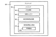
図5は、一例によるプリントヘッドを示すブロック図である。プリントヘッド501は、排障装置と使用可能である。排障装置は、媒体経路22に沿って媒体を受容して案内する、印刷システムの媒体制御部材である。印刷システムは、ページワイドアレイプリンタ等を含むことができる。プリントヘッド501は、印刷位置とメンテナンス位置との間で移動可能である。図5を参照すると、幾つかの例において、プリントヘッド501はハウジング50を含む。ハウジング50は、ノズル表面55及びノズル表面55を取り囲む拡張シュラウド56を含む。拡張シュラウド56は、媒体制御適合表面52及び媒体衝突防止表面53を含む。媒体制御適合表面52は、印刷位置において、排障装置に近接して及び当該排障装置の反対側に拡張シュラウド56を配置するために、排障装置の表面に適合する。
FIG. 5 is a block diagram illustrating a print head according to an example. The
従って、媒体の前進は、媒体搬送方向において、プリントヘッド501から下流に印刷区域から排障装置に案内されるように連続することができる。かくして、拡張シュラウド56の上での及び排障装置への媒体の位置制御が達成され得る。また、両面印刷および横目での媒体供給(例えば、媒体の幅方向において)に関してさえも、印刷区域における媒体カールに起因した媒体の衝突も、低減され得る。即ち、両面印刷において、媒体カールは、媒体の第1の面が印刷された後に形成される可能性がある。従って、媒体がその第2の面に印刷するためにプリントヘッドの印刷区域へと戻るように搬送される場合、媒体カールは、媒体衝突防止表面53に接触し且つ当該媒体衝突防止表面53により案内され得る。媒体制御適合表面52は、メンテナンス位置において排障装置から離れるように拡張シュラウド56を位置決めするために、排障装置の表面に適合する。媒体衝突防止表面53は、周期的に媒体に接触して当該媒体を排障装置に案内するための平面領域を含む。媒体衝突防止表面53は、印刷位置において、排障装置に近接して及び当該排障装置に向かい合って配置される。媒体衝突防止表面53は、メンテナンス位置において排障装置から離れるように配置される。
Thus, the advance of the media can be continuous as it is guided from the printing area to the discharge device downstream from the
図6A及び図6Bはそれぞれ、一例による、印刷位置およびメンテナンス位置にある排障装置および図5のプリントヘッドを示す側面図である。図7は、一例による、図6Aの排障装置およびプリントヘッドを示す底面図である。プリントヘッド501は、図5に関連して前述されたようなハウジング50を含む。ハウジング50は、ノズル表面55、及びノズル表面55を取り囲む拡張シュラウド56を含む。拡張シュラウド56は、媒体制御適合表面52及び媒体衝突防止表面53を含む。図6A〜図7を参照すると、幾つかの例において、媒体制御適合表面52の形状は、それに向かい合って配置される排障装置の表面の形状に適合することができる。
6A and 6B are side views, respectively, showing the discharge device and print head of FIG. 5 in the printing position and the maintenance position, according to an example. FIG. 7 is a bottom view of the reject device and print head of FIG. 6A according to an example.
係る適合により、媒体制御適合表面52と排障装置69は、印刷位置(図6A)において互いに密接に配置されるために、それらの間の間隔を低減および/または除去することが可能になることができる。例えば、媒体制御適合表面52と排障装置69との間の距離は、0.5mm未満とすることができる。更に、当該適合により、媒体制御適合表面52は、メンテナンス位置(図6B)において排障装置69から離れるように移動することを可能にすることができる。例えば、メンテナンス位置において、クリーニング装置64がプリントヘッド501を清浄化することができる。媒体制御適合表面52の形状は、排障装置69の表面の複数の突出部69aを受容し且つ当該突出部69aと対応する複数の凹み56aを含むことができる。排障装置69は、媒体35を案内するために複数のスターホイール69bを含むことができる。
Such adaptation allows the media control
図6A〜図7を参照すると、幾つかの例において、媒体衝突防止表面53は、ノズル表面55に実質的に平行である平面領域53a(図5)を含む。例えば、媒体衝突防止表面53は、ノズル表面55と実質的に同じ平面と位置合わせされて当該同じ平面に配置され得る。かくして、拡張シュラウド56から排障装置69への変り目は、それらと周期的に接触する可能性がある媒体の端部に対して滑らかであり且つ拘束しないようにすることができる。更に、媒体35の前進は、媒体搬送方向dmにおいて、プリントヘッド501から下流に拡張シュラウド56から排障装置69に案内されるように連続することができる。かくして、印刷区域における媒体カールに起因した媒体の衝突も、低減され得る。
Referring to FIGS. 6A-7, in some examples, the
図8は、一例による媒体衝突を低減する方法である。幾つかの例において、図1〜図7に関連して前述されたモジュール、及び組立体などを用いて、図8の方法を実施することができる。ブロックS810において、媒体が印刷区域へ搬送される。幾つかの例において、媒体を印刷区域へ搬送することは、両面印刷においてのような、媒体の第1の面が印刷流体を以前に受け取った後に媒体の第2の面に印刷流体を提供するために媒体を印刷区域へ搬送することを含むことができる。ブロックS812において、印刷流体は、ノズル表面およびノズル表面を取り囲むシュラウドを有するプリントヘッドにより、印刷位置において印刷区域の媒体上へ提供される。例えば、インクジェットプリントヘッドは、印刷区域に配置された媒体上へインクを吐出して、その上にイメージを形成することができる。 FIG. 8 is a method of reducing media collision according to an example. In some instances, the modules, assemblies, etc. described above in connection with FIGS. 1-7 may be used to implement the method of FIG. At block S810, the media is transported to the print area. In some instances, transporting the media to the printing area provides printing fluid to the second side of the media after the first side of the media has previously received printing fluid, such as in duplex printing. Transport the media to the printing area to At block S812, printing fluid is provided on the media of the printing area at the printing location by the print head having a nozzle surface and a shroud surrounding the nozzle surface. For example, an ink jet print head can eject ink onto media disposed in the print area to form an image thereon.
ブロックS814において、プリントヘッドに結合されたインタリーブ部材の媒体制御適合表面が、印刷位置において媒体制御部材に近接して及び媒体制御部材に向かい合って配置され、メンテナンス位置において媒体制御部材から離れて配置される。例えば、インタリーブ部材と結合されたプリントヘッドが媒体経路の方へ移動する場合、媒体制御適合表面が媒体制御部材の近くに且つ媒体制御部材と位置合わせされて配置される。例えば、インタリーブ部材を有するプリントヘッドが媒体経路から離れるように移動する場合、媒体制御適合表面は媒体制御部材から離れるように移動する。幾つかの例において、媒体制御適合表面の形状は、媒体制御部材の表面の複数の突出部を受容し且つ当該突出部と対応する複数の凹みを含む。 At block S814, a media control compliant surface of the interleaving member coupled to the print head is positioned proximate to the media control member in the printing position and opposite the media control member and spaced apart from the media control member in the maintenance position Ru. For example, when the print head coupled to the interleaving member is moved toward the media path, the media control compliant surface is positioned near the media control member and aligned with the media control member. For example, if a printhead having an interleaving member moves away from the media path, the media control compliant surface moves away from the media control member. In some instances, the shape of the media control compliant surface includes a plurality of protrusions on the surface of the media control member and includes a plurality of recesses corresponding to the protrusions.
ブロックS816において、インタリーブ部材のシュラウド適合表面は、印刷位置およびメンテナンス位置において、シュラウドに近接して且つシュラウドの向かい側に維持される。例えば、インタリーブ部材は、シュラウド適合表面とシュラウドとの間に僅かな一定量の空間(スペース)が存在するように、プリントヘッドに取り付けられる。 At block S816, the shroud compatible surface of the interleave member is maintained proximate to the shroud and opposite the shroud in the printing position and the maintenance position. For example, the interleaving member may be attached to the print head such that there is a small amount of space between the shroud compatible surface and the shroud.
ブロックS818において、インタリーブ部材の媒体衝突防止表面は、周期的に媒体に接触して当該媒体を媒体制御部材に案内するために印刷位置において、ノズル表面に近接して配置され、メンテナンス位置においてノズル表面から離れて配置される。例えば、インタリーブ部材と結合されたプリントヘッドが媒体経路の方へ移動する場合、媒体衝突防止表面がノズル表面の近くに且つ当該ノズル表面と位置合わせされて配置される。代案として、例えば、インタリーブ部材を有するプリントヘッドが媒体経路から離れるように移動する場合、媒体衝突防止表面がノズル表面から離れるように移動する。幾つかの例において、周期的に媒体に接触して当該媒体を媒体制御部材に案内するために印刷位置において、ノズル表面に近接してインタリーブ部材の媒体衝突防止表面を配置し、メンテナンス位置においてノズル表面から離れて配置することは、媒体衝突防止表面をノズル表面に実質的に平行に配置することを含むことができる。例えば、媒体衝突防止表面は、ノズル表面と実質的に同じ平面と位置合わせされ且つ当該同じ平面に配置され得る。 At block S 818, the media anti-collision surface of the interleave member is positioned proximate to the nozzle surface at the print position to periodically contact the media to guide the media to the media control member and at the maintenance position It is placed away from. For example, when the print head coupled to the interleaving member moves toward the media path, the media anti-collision surface is positioned near and aligned with the nozzle surface. Alternatively, the media anti-collision surface is moved away from the nozzle surface, for example, when the print head with the interleaving member is moved away from the media path. In some instances, the media anti-collision surface of the interleave member is positioned proximate the nozzle surface at the printing position to periodically contact the media and guide the media to the media control member, and the nozzle at the maintenance position Positioning away from the surface can include positioning the media anti-collision surface substantially parallel to the nozzle surface. For example, the media anti-collision surface may be aligned with and disposed in substantially the same plane as the nozzle surface.
理解されるべきは、図8の流れ図は、本開示のアーキテクチュア例、機能例、及び/又は動作例を示す。図8の流れ図は特定順序の実行を示すが、実行の順序は、図示されたものとは異なってもよい。例えば、2つ以上のブロックの実行の順序は、図示された順序に対して並べ替えられてもよい。また、図8において連続して示された2つ以上のブロックは、同時に又は部分的に同時に実行され得る。係る全ての変形態様は、本開示の範囲内にある。 It should be understood that the flow diagram of FIG. 8 illustrates example architecture, example functions, and / or example operations of the present disclosure. Although the flowchart of FIG. 8 shows the execution of a specific order, the order of execution may be different than that shown. For example, the order of execution of two or more blocks may be rearranged to the illustrated order. Also, two or more blocks shown sequentially in FIG. 8 may be performed simultaneously or partially simultaneously. All such variations are within the scope of the present disclosure.
本開示は、大まかな発明概念の範囲を制限することが意図されていないその例に関する制限しない詳細な説明を用いて説明された。理解されるべきは、一例に関して説明された特徴および/または動作は、他の例と共に使用されることができ、全てとは限らない例は、特定の図面に示された又は例の1つに関して説明された特徴および/または動作の全てを有する。説明された例に関する変形態様については、当業者が思いつくであろう。更に、用語「からなる」、「含む」、「有する」及びそれらの活用形は、本開示および/または特許請求の範囲において使用される場合、「必ずしも・・に制限されないが・・を含む」を意味するものとする。 The present disclosure has been described using non-limiting detailed description of its examples, which is not intended to limit the scope of the broad inventive concept. It should be understood that the features and / or operations described with respect to one example may be used with other examples, and not all examples may be illustrated in particular drawings or with respect to one of the examples. It has all of the described features and / or actions. Those skilled in the art will recognize variations on the described examples. Furthermore, the terms "consisting of," "including," "having," and variants thereof, as used in the present disclosure and / or claims, "includes, but is not necessarily limited to, ..." Shall mean.
留意すべきは、上述された例の幾つかは、大まかな発明概念に不可欠ではないかもしれない構造、動作または構造と動作の細部を含むことができ、それらは例証目的のために説明された。本明細書で説明された構造および動作は、当該技術において知られているように、構造または動作が異なる場合でさえも同じ機能を実行する等価物により、入れ換え可能である。従って、大まかな発明概念の範囲は、特許請求の範囲において使用されるような要素および制限によってのみ制限される。 It should be noted that some of the examples described above may include structure, operation or details of structure and operation that may not be essential to the broad inventive concept, which are described for illustrative purposes . The structures and operations described herein may be interchanged with equivalents that perform the same function even as the structures or operations differ, as is known in the art. Accordingly, the scope of the broad inventive concept is limited only by the elements and limitations as used in the claims.
Claims (14)
ノズル表面を取り囲むシュラウドを有すると共に、印刷位置とメンテナンス位置との間で移動可能なプリントヘッドに結合し、シュラウド適合表面、媒体制御適合表面、及び媒体衝突防止表面を含むインタリーブ部材を含み、
前記シュラウド適合表面が前記シュラウドに近接して及び前記シュラウドに向かい合って配置され、
前記媒体制御適合表面が、前記印刷位置において媒体制御部材に近接して及び前記媒体制御部材に向かい合って配置され、前記メンテナンス位置において前記媒体制御部材から離れて配置され、
前記媒体衝突防止表面が、前記印刷位置において、媒体に接触した際に当該媒体を前記媒体制御部材へ案内し、
前記媒体衝突防止表面が、前記ノズル表面と実質的に同じ平面と位置合わせされて当該同じ平面に配置される、媒体衝突防止装置。 A media anti-collision device usable with a print head, comprising:
A shroud having a shroud surrounding the nozzle surface and coupled to the print head movable between the printing position and the maintenance position, including an interleave member including a shroud compatible surface, a media control compliant surface, and a media anti-collision surface;
The shroud conforming surface is disposed proximate to the shroud and opposite the shroud;
The media control compliant surface is disposed adjacent to and facing the media control member at the printing position and spaced apart from the media control member at the maintenance position;
The media anti-collision surface guides the media to the media control member when in contact with the media at the printing position ;
A media anti-collision device, wherein the media anti-collision surface is positioned in the same plane, aligned with substantially the same plane as the nozzle surface .
ノズル表面、及び前記ノズル表面を取り囲む拡張シュラウドを含むハウジングを含み、
前記拡張シュラウドが媒体制御適合表面および媒体衝突防止表面を含み、
前記媒体制御適合表面が、前記印刷位置において前記排障装置に近接して且つ前記排障装置の反対側に前記拡張シュラウドを配置するために、及び前記メンテナンス位置において前記排障装置から離して前記拡張シュラウドを配置するために、前記排障装置の表面に適合し、
前記媒体衝突防止表面が、媒体に接触した際に当該媒体を前記排障装置へ案内するための平面領域を含み、前記媒体衝突防止表面が、前記印刷位置において前記排障装置に近接して且つ前記排障装置に向かい合って配置され、前記メンテナンス位置において前記排障装置から離れて配置される、プリントヘッド。 A print head movable between a printing position and a maintenance position and usable with a fault relief device,
A housing including a nozzle surface and an expansion shroud surrounding the nozzle surface;
The expansion shroud includes a media control compliant surface and a media anti-collision surface,
The media control compliant surface is for positioning the expansion shroud in proximity to the obstruction device at the printing position and opposite the obstruction device, and away from the obstruction device at the maintenance position. Conform to the surface of the obstruction device to locate the expansion shroud;
The medium anti-collision surface includes a flat area for guiding the medium to the discharge device when in contact with the medium, the medium anti-collision surface being proximate to the discharge device at the printing position and A print head disposed opposite the fault relief device and spaced apart from the fault relief device at the maintenance position.
前記媒体を印刷区域へ搬送し、
ノズル表面および前記ノズル表面を取り囲むシュラウドを有するプリントヘッドにより、印刷位置において前記印刷区域の前記媒体上へ印刷流体を提供し、
印刷位置において、前記プリントヘッドに結合されたインタリーブ部材の媒体制御適合表面を、媒体制御部材に近接して且つ当該媒体制御部材に向かい合って配置し、メンテナンス位置において前記媒体制御部材から離して配置し、
前記印刷位置および前記メンテナンス位置において、前記シュラウドに近接して且つ前記シュラウドに向かい合って前記インタリーブ部材のシュラウド適合表面を維持し、
前記印刷位置において、媒体に接触した際に当該媒体を前記媒体制御部材へ案内するために前記ノズル表面に近接して前記インタリーブ部材の媒体衝突防止表面を配置し、前記メンテナンス位置において前記ノズル表面から離して配置することを含む、方法。 A method of reducing media collisions, comprising
Transport the medium to the printing area;
Providing a printing fluid on the medium of the printing area at a printing position by means of a printhead having a nozzle surface and a shroud surrounding the nozzle surface;
In the printing position, a media control compliant surface of the interleaving member coupled to the print head is disposed proximate to and facing the media control member and spaced apart from the media control member in the maintenance position. ,
Maintaining a shroud compatible surface of the interleave member adjacent the shroud and facing the shroud in the printing position and the maintenance position;
In the printing position, the medium collision preventing surface of the interleaving member is disposed in proximity to the nozzle surface to guide the medium to the medium control member when contacting the medium, and from the nozzle surface in the maintenance position A method that involves placing apart.
前記媒体衝突防止表面を前記ノズル表面に実質的に平行に配置することを更に含む、請求項10に記載の方法。 In the printing position, the medium collision preventing surface of the interleaving member is disposed in proximity to the nozzle surface to guide the medium to the medium control member when contacting the medium, and from the nozzle surface in the maintenance position It can be placed apart,
11. The method of claim 10 , further comprising disposing the media anti-collision surface substantially parallel to the nozzle surface.
前記媒体衝突防止表面を、前記ノズル表面と実質的に同じ平面と位置合わせし且つ当該同じ平面に配置することを更に含む、請求項10に記載の方法。 In the printing position, the medium collision preventing surface of the interleaving member is disposed in proximity to the nozzle surface to guide the medium to the medium control member when contacting the medium, and from the nozzle surface in the maintenance position It can be placed apart,
11. The method of claim 10 , further comprising aligning and positioning the media anti-collision surface substantially in the same plane as the nozzle surface.
前記媒体の第1の面が印刷流体を以前に受け取った後に、前記媒体の第2の面上に印刷流体を提供するために前記媒体を前記印刷区域へ搬送することを更に含む、請求項10〜12の何れかに記載の方法。 Conveying the medium to a printing area;
11. The method of claim 10 , further comprising conveying the media to the printing area to provide printing fluid on a second side of the media after the first side of the media has previously received printing fluid. the method according to any one of ~ 12.
Applications Claiming Priority (1)
| Application Number | Priority Date | Filing Date | Title |
|---|---|---|---|
| PCT/US2014/051710 WO2016028281A1 (en) | 2014-08-19 | 2014-08-19 | Media crash prevention surface to contact and guide media |
Related Child Applications (1)
| Application Number | Title | Priority Date | Filing Date |
|---|---|---|---|
| JP2019014979A Division JP6657439B2 (en) | 2019-01-31 | 2019-01-31 | Media anti-collision surface for guiding and contacting media |
Publications (2)
| Publication Number | Publication Date |
|---|---|
| JP2017525593A JP2017525593A (en) | 2017-09-07 |
| JP6513186B2 true JP6513186B2 (en) | 2019-05-15 |
Family
ID=55351071
Family Applications (1)
| Application Number | Title | Priority Date | Filing Date |
|---|---|---|---|
| JP2017510365A Active JP6513186B2 (en) | 2014-08-19 | 2014-08-19 | Medium anti-collision surface for guiding in contact with medium |
Country Status (5)
| Country | Link |
|---|---|
| US (1) | US9931866B2 (en) |
| JP (1) | JP6513186B2 (en) |
| KR (1) | KR102278733B1 (en) |
| CN (1) | CN107073945B (en) |
| WO (1) | WO2016028281A1 (en) |
Family Cites Families (22)
| Publication number | Priority date | Publication date | Assignee | Title |
|---|---|---|---|---|
| JP2925748B2 (en) | 1990-12-20 | 1999-07-28 | シチズン時計株式会社 | Paper guide device for printer |
| JPH05162397A (en) * | 1991-12-11 | 1993-06-29 | Tokyo Electric Co Ltd | Printer |
| US5414453A (en) * | 1993-04-30 | 1995-05-09 | Hewlett-Packard Company | Use of a densitometer for adaptive control of printhead-to-media distance in ink jet printers |
| JPH09254472A (en) | 1996-03-22 | 1997-09-30 | Pfu Ltd | Paper feed device for printer |
| JPH09255201A (en) * | 1996-03-26 | 1997-09-30 | Canon Inc | Image forming device |
| JP3658159B2 (en) * | 1997-11-13 | 2005-06-08 | キヤノン株式会社 | Recording device |
| US20010046405A1 (en) * | 1998-08-31 | 2001-11-29 | Kenichi Miyazaki | Large printer |
| US6908242B2 (en) | 2001-12-04 | 2005-06-21 | Seiko Epson Corporation | Roll paper curl correction device and record apparatus with the roll paper curl correction device |
| WO2005070689A1 (en) * | 2004-01-21 | 2005-08-04 | Silverbrook Research Pty Ltd | Self contained wallpaper printer |
| JP2006076144A (en) * | 2004-09-09 | 2006-03-23 | Tohoku Ricoh Co Ltd | Image forming device |
| JP5200878B2 (en) * | 2008-11-19 | 2013-06-05 | 株式会社リコー | Image forming apparatus |
| JP2011016316A (en) * | 2009-07-09 | 2011-01-27 | Sony Corp | Liquid ejecting apparatus |
| JP5330284B2 (en) * | 2010-01-28 | 2013-10-30 | 富士通フロンテック株式会社 | Printing device |
| JP5340254B2 (en) | 2010-11-29 | 2013-11-13 | キヤノン株式会社 | Printing device |
| JP2012166867A (en) * | 2011-02-10 | 2012-09-06 | Seiko Epson Corp | Recording device |
| US9002257B2 (en) * | 2011-08-01 | 2015-04-07 | Ricoh Company, Ltd. | Image forming apparatus |
| US8376498B1 (en) | 2011-10-03 | 2013-02-19 | Xerox Corporation | High productivity spreader/transfix system for duplex media sheets in an inkjet printer |
| JP5857748B2 (en) * | 2012-01-05 | 2016-02-10 | セイコーエプソン株式会社 | Liquid ejector |
| JP6094158B2 (en) | 2012-01-31 | 2017-03-15 | 株式会社リコー | Image forming apparatus and curl correction method |
| GB2515229B (en) * | 2012-04-10 | 2018-11-21 | Hewlett Packard Development Co | Print media guide |
| CN104302484B (en) * | 2012-06-26 | 2016-09-07 | 惠普发展公司,有限责任合伙企业 | media guide |
| US8746694B2 (en) | 2012-10-05 | 2014-06-10 | Xerox Corporation | In-line substrate media sensor and protective guide |
-
2014
- 2014-08-19 JP JP2017510365A patent/JP6513186B2/en active Active
- 2014-08-19 KR KR1020177007325A patent/KR102278733B1/en active IP Right Grant
- 2014-08-19 US US15/505,579 patent/US9931866B2/en active Active
- 2014-08-19 WO PCT/US2014/051710 patent/WO2016028281A1/en active Application Filing
- 2014-08-19 CN CN201480082083.1A patent/CN107073945B/en active Active
Also Published As
| Publication number | Publication date |
|---|---|
| WO2016028281A1 (en) | 2016-02-25 |
| US9931866B2 (en) | 2018-04-03 |
| KR20170042751A (en) | 2017-04-19 |
| KR102278733B1 (en) | 2021-07-16 |
| CN107073945A (en) | 2017-08-18 |
| CN107073945B (en) | 2018-05-29 |
| JP2017525593A (en) | 2017-09-07 |
| US20170266994A1 (en) | 2017-09-21 |
Similar Documents
| Publication | Publication Date | Title |
|---|---|---|
| KR0184571B1 (en) | Paper jam preventing structure for inkjet printer | |
| JP6252725B2 (en) | Recording device | |
| JP2004114406A (en) | Inkjet printer | |
| US9975339B2 (en) | Shroud for a printhead assembly | |
| US9315046B2 (en) | Recording apparatus | |
| CN104553327B (en) | Liquid liquid discharging device | |
| US20130215206A1 (en) | Printer | |
| JP6513186B2 (en) | Medium anti-collision surface for guiding in contact with medium | |
| US20160214383A1 (en) | Head unit and recording apparatus | |
| JP6115255B2 (en) | Recording device | |
| JP2019077190A (en) | Media crash prevention surface to contact and guide media | |
| JP6186810B2 (en) | Image forming apparatus | |
| JP2018203425A5 (en) | ||
| EP2754560B1 (en) | Recording apparatus | |
| US9162483B2 (en) | Recording apparatus | |
| US9776431B2 (en) | Medium conveying device and image recording apparatus | |
| JP2016000643A (en) | Image forming apparatus | |
| US10308052B2 (en) | Inkjet printer which stiffens sheet | |
| JP5311753B2 (en) | Image forming apparatus | |
| JP5637733B2 (en) | Inkjet recording device | |
| JP2010280230A5 (en) | ||
| JP6232918B2 (en) | Tension device using air | |
| JP2010214618A (en) | Printing apparatus | |
| JP2016168759A (en) | Recording apparatus | |
| JP2000198604A (en) | Recording device |
Legal Events
| Date | Code | Title | Description |
|---|---|---|---|
| A621 | Written request for application examination |
Free format text: JAPANESE INTERMEDIATE CODE: A621 Effective date: 20170228 |
|
| A131 | Notification of reasons for refusal |
Free format text: JAPANESE INTERMEDIATE CODE: A131 Effective date: 20171212 |
|
| A521 | Request for written amendment filed |
Free format text: JAPANESE INTERMEDIATE CODE: A523 Effective date: 20180307 |
|
| A131 | Notification of reasons for refusal |
Free format text: JAPANESE INTERMEDIATE CODE: A131 Effective date: 20180703 |
|
| A02 | Decision of refusal |
Free format text: JAPANESE INTERMEDIATE CODE: A02 Effective date: 20181106 |
|
| A521 | Request for written amendment filed |
Free format text: JAPANESE INTERMEDIATE CODE: A523 Effective date: 20190131 |
|
| A911 | Transfer to examiner for re-examination before appeal (zenchi) |
Free format text: JAPANESE INTERMEDIATE CODE: A911 Effective date: 20190207 |
|
| TRDD | Decision of grant or rejection written | ||
| A01 | Written decision to grant a patent or to grant a registration (utility model) |
Free format text: JAPANESE INTERMEDIATE CODE: A01 Effective date: 20190326 |
|
| A61 | First payment of annual fees (during grant procedure) |
Free format text: JAPANESE INTERMEDIATE CODE: A61 Effective date: 20190409 |
|
| R150 | Certificate of patent or registration of utility model |
Ref document number: 6513186 Country of ref document: JP Free format text: JAPANESE INTERMEDIATE CODE: R150 |
|
| R250 | Receipt of annual fees |
Free format text: JAPANESE INTERMEDIATE CODE: R250 |
|
| R250 | Receipt of annual fees |
Free format text: JAPANESE INTERMEDIATE CODE: R250 |
|
| R250 | Receipt of annual fees |
Free format text: JAPANESE INTERMEDIATE CODE: R250 |
|
| RD02 | Notification of acceptance of power of attorney |
Free format text: JAPANESE INTERMEDIATE CODE: R3D02 |