JP6512934B2 - Fire extinguishing equipment - Google Patents
Fire extinguishing equipment Download PDFInfo
- Publication number
- JP6512934B2 JP6512934B2 JP2015101978A JP2015101978A JP6512934B2 JP 6512934 B2 JP6512934 B2 JP 6512934B2 JP 2015101978 A JP2015101978 A JP 2015101978A JP 2015101978 A JP2015101978 A JP 2015101978A JP 6512934 B2 JP6512934 B2 JP 6512934B2
- Authority
- JP
- Japan
- Prior art keywords
- water spray
- spray head
- pipe
- open
- open water
- Prior art date
- Legal status (The legal status is an assumption and is not a legal conclusion. Google has not performed a legal analysis and makes no representation as to the accuracy of the status listed.)
- Active
Links
- XLYOFNOQVPJJNP-UHFFFAOYSA-N water Substances O XLYOFNOQVPJJNP-UHFFFAOYSA-N 0.000 claims description 125
- 239000007921 spray Substances 0.000 claims description 76
- 238000001514 detection method Methods 0.000 claims description 11
- 238000013459 approach Methods 0.000 description 3
- 238000009434 installation Methods 0.000 description 3
- 229910000831 Steel Inorganic materials 0.000 description 2
- 238000010586 diagram Methods 0.000 description 2
- 230000000630 rising effect Effects 0.000 description 2
- 239000010959 steel Substances 0.000 description 2
- 239000000446 fuel Substances 0.000 description 1
Images


Landscapes
- Fire-Extinguishing By Fire Departments, And Fire-Extinguishing Equipment And Control Thereof (AREA)
Description
消火設備に関する。 Regarding fire extinguishing equipment.
高天井にスプリンクラーヘッドを設置する消火設備が知られている(特許文献1参照)。 DESCRIPTION OF RELATED ART The fire extinguishing installation which installs a sprinkler head in a high ceiling is known (refer patent document 1).
しかしながら、上記従来の消火設備では、スプリンクラーヘッドから放出された水の水勢が、空気抵抗などにより、自動車に到達するまでの間に減じられてしまう虞がある。 However, in the above-mentioned conventional fire extinguishing equipment, there is a possibility that the water pressure of the water discharged from the sprinkler head may be reduced until it reaches the vehicle due to air resistance or the like.
上記課題は、例えば、次の手段により解決される。すなわち、屋内駐車場に設置される消火設備であって、加圧送水装置に流水検知装置を介して接続される第1配管と、前記屋内駐車場の天井面に設置される感熱開放継手と、前記感熱開放継手を介して前記第1配管に接続され、前記屋内駐車場の天井面側から床面側へ向けて延伸する延伸部を備えた第2配管と、前記第2配管の延伸部に接続され、自動車に近接する開放型水噴霧ヘッドと、を備えたことを特徴とする消火設備である。 The above-mentioned subject is solved by the following means, for example. That is, it is a fire extinguishing facility installed in an indoor parking lot, which is a first pipe connected to a pressurized water supply device via a water flow detection device, and a heat-sensitive open joint installed on a ceiling surface of the indoor parking lot; A second pipe connected to the first pipe via the heat-sensitive open joint and having a drawing portion extending from the ceiling surface side to the floor surface side of the indoor parking lot, and a drawing portion of the second pipe An open water spray head connected and in proximity to a car.
上記の消火設備によれば、自動車から噴き出る炎の火勢に負けない水勢でもって、自動車の内部にまで十分な量の水を到達させることができる。 According to the above-described fire extinguishing system, a sufficient amount of water can be made to reach the inside of the car with a water flow that can not be defeated by the flames of the flame emitted from the car.
[実施形態1に係る消火設備1]
図1は実施形態1に係る消火設備を示す模式図である。図1に示すように、実施形態1に係る消火設備1は、屋内駐車場に設置される消火設備であって、加圧送水装置10に流水検知装置20を介して接続される第1配管30と、屋内駐車場の天井面に設置される感熱開放継手40と、感熱開放継手40を介して第1配管30に接続され、屋内駐車場の天井面側から床面側へ向けて延伸する延伸部50aを備えた第2配管50と、第2配管50の延伸部50aに接続され、自動車に近接する開放型水噴霧ヘッド70と、を備えた消火設備である。以下、詳細に説明する。
[Fire Fighting Equipment 1 According to Embodiment 1]
FIG. 1 is a schematic view showing the fire extinguishing equipment according to the first embodiment. As shown in FIG. 1, the fire extinguishing equipment 1 according to the first embodiment is a fire extinguishing equipment installed in an indoor parking lot, and a
(屋内駐車場)
屋内駐車場とは例えばビルやマンションなどの建物内に設けられた駐車場をいう。屋内駐車場は例えば複数の駐車区画(例:白い線で床面に引かれた囲み、機械式屋内駐車場における各段)を有しており、各駐車区画には例えば1台の自動車(例:普通自動車、軽自動車、自動二輪車)を駐車することができる。なお、自動車は、ガソリン自動車であってもよいし、燃料電池自動車などのような新しいタイプの自動車であってもよい。
(Indoor parking lot)
An indoor parking lot means the parking lot provided in buildings, such as a building and an apartment, for example. The indoor parking lot has, for example, a plurality of parking areas (e.g. a box drawn on the floor with white lines, each stage in a mechanical indoor parking area), and each parking area has, for example, one car. : Can park ordinary cars, mini cars, motorcycles). The car may be a gasoline car or a new type of car such as a fuel cell car.
(加圧送水装置10)
加圧送水装置10は貯水層100に貯水された水や消火栓から供給される水などを所定の圧力でもって第1配管30に送水する装置である。所定の圧力は、特に限定されるものではないが、例えば、0.35MPa以上1.4MPa以下の範囲内にあることが好ましい。加圧送水装置10には例えばポンプや圧力タンクなどを用いることができる。貯水層100は例えばビルの地下に設置される。
(Pressure water supply device 10)
The pressurized
(流水検知装置20)
流水検知装置20は第1配管30中の流水を検知する装置である。第1配管30中の流水を検知することによって、火災が生じているかどうかを判断することができる。流水検知装置20には、例えば、自動警報弁型、作動弁型、またはパドル型のものを用いることができる。
(Water flow detection device 20)
The water
(第1配管30)
第1配管30には例えば鋼管を用いることができる。第1配管30は加圧送水装置10に流水検知装置20を介して接続される。第1配管30と加圧送水装置10との間には、流水検知装置20が介在する限り、流水検知装置20以外の他の装置がさらに介在していてもよい。
(First pipe 30)
For example, a steel pipe can be used for the
(感熱開放継手40)
感熱開放継手40とは、第1配管30と第2配管50との間における流路を閉鎖する閉鎖部と、所定量以上の熱を感知した場合に第1配管30と第2配管50との間における流路を開放する感知部と、をあわせ持つ装置である。閉鎖部のみを有する装置(例:一斉開放弁)や感知部のみを有する装置は感熱開放継手40から除かれる。
(Thermal opening joint 40)
The heat-sensitive
感熱開放継手40は屋内駐車場の天井面に設置される。具体的に説明すると、感熱開放継手40は、例えば、0<感熱開放継手40と天井面との最短距離≦30cmの条件を満たすように設置される。自動車火災が生じると、自動車周辺の空気が暖められ天井面に向けた熱上昇気流が発生するが、天井面に達した熱上昇気流は天井面に沿って流動展開していく。したがって、感熱開放継手40を屋内駐車場の天井面に設置すれば、屋内駐車場にて生じた火災をいち早く検知することができる。
The
感熱開放継手40は、自動車の駐車位置(屋内駐車場が自動車の横幅・縦幅とほぼ同じ横幅・縦幅を有する駐車区画を有する場合には駐車区画。以下、同じ。)とは無関係に設置することもできるが、自動車の駐車位置を考慮した位置に設置されることが好ましく、特に、自動車の駐車位置の右側上方、左側上方、前側上方、または後側上方に設置されることが好ましい。自動車火災においては、自動車の内部に火源があることが多く、前述した熱上昇気流は、窓やエンジンルームなどがある自動車の右側、左側、前側、または後側にて生じやすい。したがって、上記の位置に感熱開放継手40を設置すれば、屋内駐車場にて生じた火災をより早く検知することができる。
The
(第2配管50)
第2配管50には例えば鋼管を用いることができる。第2配管50は感熱開放継手40を介して第1配管30に接続される。第1配管30と第2配管50との間には、感熱開放継手40が介在する限り、感熱開放継手40以外の他の装置がさらに介在していてもよい。
(Second pipe 50)
For example, a steel pipe can be used for the
第2配管50は屋内駐車場の天井面側から床面側へ向けて延伸する延伸部50aを備えている。このような延伸部50aを第2配管50が備えることにより、開放型水噴霧ヘッド70を自動車に近接する位置に設置することが可能となる。なお、第2配管50は、延伸部50aとは別に、屋内駐車場の天井面に沿って設置される天井面沿い部50bなどを備えていてもよい。
The
開放型水噴霧ヘッド70を自動車に近接させることができる程度の長さを有する限り、延伸部50aの具体的な長さは特に限定されない。また、延伸部50aは、例えば、直線状、曲線状、あるいはこれらを組み合わせた様々な形状に形成することができる。
The specific length of the
(開放型水噴霧ヘッド70:近接)
開放型水噴霧ヘッド70とは感熱部を有さず出口が常に開放された水噴霧ヘッドをいう。開放型水噴霧ヘッド70は、例えば、第2配管50に接続されるノズルと、ノズルから噴射された水を散水するデフレクタと、を備えている。
(Open water spray head 70: proximity)
The open-type
開放型水噴霧ヘッド70は、第2配管50の延伸部50aに接続され、自動車に近接する。このように、開放型水噴霧ヘッド70が自動車に近接することにより、開放型水噴霧ヘッド70から放出される水の水勢が空気抵抗などを受けて自動車に到達するまでの間に減じられてしまうことが防止される。
The open
開放型水噴霧ヘッド70と自動車との近接の程度(開放型水噴霧ヘッド70と自動車の最短距離)は、特に限定されるものではないが、好ましくは1cm以上2m以下であり、より好ましくは3cm以上90cm以下であり、さらに好ましくは44cm以上46cm以下であり、望ましくは45cm程度である。最短距離がこれらの範囲内にあれば、開放型水噴霧ヘッド70と自動車との緩衝を回避しつつ、自動車から噴き出る炎の火勢に負けない水勢でもって、自動車の内部にまで十分な量の水を到達させることができる。なお、開放型水噴霧ヘッド70は、自動車に近接する限り、延伸部50a中のどの部位に接続されてもよく、例えば、延伸部50aにおける延伸元側の部位に接続することもできるし、延伸先側の部位に接続することもできるし、延伸の先端に接続することもできる。
The degree of proximity between the open
開放型水噴霧ヘッド70の数は特に限定されず、1つ以上であればよい。例えば、本実施形態では、開放型水噴霧ヘッド70として、2つの開放型水噴霧ヘッド70(自動車の右側に設置される開放型水噴霧ヘッド71、自動車の左側に設置される開放型水噴霧ヘッド72)が設けられるものとするが、これは一例である。また、開放型水噴霧ヘッド70は、例えば、自動車の右側と左側にそれぞれ設置することができるほか、前側と後側にそれぞれ設置することもできるし、右側、左側、前側、及び後側にそれぞれ設置することもできる。
The number of open water spray heads 70 is not particularly limited, and may be one or more. For example, in the present embodiment, two open water spray heads 70 (open water spray heads 71 installed on the right side of the vehicle, open water spray heads installed on the left side of the vehicle are used as the open
開放型水噴霧ヘッド70は、屋内駐車場の床面側に向けて散水するよう設置されてもよいし、天井面側に向けて散水するよう設置されてもよい。また、近接する自動車に向けて散水するよう設置されてもよい。
The open
(開放型水噴霧ヘッド80:上方)
消火設備1は、開放型水噴霧ヘッド70とは別に、第2配管50に接続され、自動車の上方に設置される開放型水噴霧ヘッド80を備えていてもよい。このようにすれば、火源を有する自動車を包み込むよう、該自動車の上方から該自動車に向けてカーテン状に水を散水させることができるため、隣接する自動車への延焼を効果的に防止することができる。なお、自動車の上方に設置される開放型水噴霧ヘッド80は、自動車に近接する位置に設置されてもよいし、当該位置に設置されなくてもよい。一例を挙げると、開放型水噴霧ヘッド80は、例えば、屋内駐車場の天井面との最短距離が例えば30cm以下となる位置に設置することができる。
(Open water spray head 80: upward)
The fire extinguishing facility 1 may be provided with an open
以上のとおり、実施形態1に係る消火設備1では、第2配管50が屋内駐車場の天井面側から床面側へ向けて延伸する延伸部50aを備えるとともに、開放型水噴霧ヘッド70が第2配管50の延伸部50aに接続され、自動車に近接する。したがって、実施形態1に係る消火設備1によれば、開放型水噴霧ヘッド70から放出された水の水勢が空気抵抗などを受けて自動車に到達するまでの間に減じられてしまうことを防止することができる。よって、自動車から噴き出る炎の火勢に負けない水勢でもって、自動車の内部にまで十分な量の水を到達させることができる。
As described above, in the fire extinguishing equipment 1 according to the first embodiment, the
[実施形態2に係る消火設備2]
図2は実施形態2に係る消火設備を示す模式図である。図2に示すように、実施形態2に係る消火設備2は、屋内駐車場が複数段の機械式屋内駐車場であり、開放型水噴霧ヘッド70として、各段の自動車に近接する複数の開放型水噴霧ヘッド71、72を備える点で、実施形態1に係る消火設備1と相違する。実施形態2に係る消火設備2によっても、実施形態1に係る消火設備1と同様に、自動車から噴き出る炎の火勢に負けない水勢でもって自動車の内部にまで十分な量の水を到達させることができる。
[Fire Fighting Equipment 2 According to Embodiment 2]
FIG. 2 is a schematic view showing a fire extinguishing system according to a second embodiment. As shown in FIG. 2, the fire extinguishing equipment 2 according to the second embodiment is a mechanical indoor parking lot having a plurality of indoor parking lots, and as the open
(閉鎖型水噴霧ヘッド90)
なお、図2に示したように、実施形態2に係る消火設備2は、感熱開放継手40を介することなく第1配管30に接続される第3配管60と、第3配管60に接続され、最上段の自動車の上方に設置される閉鎖型水噴霧ヘッド90を備えていてもよい。このようにすれば、火源を有する自動車を包み込むよう、該自動車の上方から該自動車に向けてカーテン状に水を散水させることができるため、隣接する自動車への延焼を効果的に防止することができる。なお、閉鎖型水噴霧ヘッド90は自動車に近接する位置に設置されてもよいし、当該位置に設置されなくてもよい。一例を挙げると、閉鎖型水噴霧ヘッド90は、例えば、屋内駐車場の天井面との最短距離が30cm以下となる位置に設置することができる。
(Closed water spray head 90)
As shown in FIG. 2, the fire extinguishing equipment 2 according to the second embodiment is connected to the
閉鎖型水噴霧ヘッド90とは、感熱部を有し、平常時においては出口が閉鎖されているが、感熱部が所定量以上の熱を感知した場合には出口が開放される水噴霧ヘッドをいう。閉鎖型水噴霧ヘッド90は、例えば、第3配管60に接続されるノズルと、ノズルの出口を閉鎖する閉鎖部と、所定量以上の熱を感知した場合に閉鎖部による閉鎖を開放する感知部と、ノズルから噴射された水を散水するデフレクタと、を備えている。
The closed type
[実施形態3に係る消火設備3]
図3は実施形態3に係る消火設備を示す模式図である。図3に示すように、実施形態3に係る消火設備3は、最上段の自動車に対しては近接する位置に開放型水噴霧ヘッド70が設置されず、その代わりに、最上段の自動車の上方に閉鎖型水噴霧ヘッド90が必ず設置される点で、実施形態2に係る消火設備2と相違する。実施形態3に係る消火設備3によっても、実施形態2に係る消火設備2と同様に、自動車から噴き出る炎の火勢に負けない水勢でもって自動車の内部にまで十分な量の水を到達させることができる。
[Fire Fighting Equipment 3 According to Embodiment 3]
FIG. 3 is a schematic view showing a fire extinguishing system according to a third embodiment. As shown in FIG. 3, in the fire extinguishing system 3 according to the third embodiment, the open
[デフレクタの開き角度]
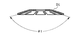
図4Aは自動車に近接する開放型水噴霧ヘッドのデフレクタの模式的平面図であり、図4Bは図4A中のA−A断面図である。また、図5Aは自動車の上方に設置される開放型(閉鎖型)水噴霧ヘッドのデフレクタの模式的平面図であり、図5Bは図5A中のB−B断面図である。図4A、図4B、図5A、図5Bに示すように、自動車の上方に設置される開放型(閉鎖型)水噴霧ヘッド80、90のデフレクタD2の開き角度θ2は、自動車に近接する開放型水噴霧ヘッド70のデフレクタD1の開き角度θ1より小さいことが好ましい。このようにすれば、自動車の上方に設置される開放型(閉鎖型)水噴霧ヘッド80、90の散水エリアが狭まるため、火源を有する自動車を包み込むよう、該自動車の上方から該自動車に向けてカーテン状に水を散水させることができる。また、自動車に近接する開放型水噴霧ヘッド70の散水エリアが広がるため、隣接する自動車に向けても散水することが可能となり、隣接する自動車への延焼を効果的に防止することができる。
[Deflector opening angle]
FIG. 4A is a schematic plan view of a deflector of an open water spray head adjacent to a car, and FIG. 4B is a cross-sectional view taken along line A-A in FIG. 4A. 5A is a schematic plan view of a deflector of an open (closed) water spray head installed above the automobile, and FIG. 5B is a cross-sectional view taken along the line B-B in FIG. 5A. As shown in FIGS. 4A, 4B, 5A and 5B, the opening angle θ2 of the deflector D2 of the open (closed)
以上、実施形態について説明したが、これらの説明は一例に関するものであり、特許請求の範囲に記載された構成を何ら限定されるものではない。 Although the embodiments have been described above, these descriptions relate to an example, and the configuration described in the claims is not limited at all.
1、2、3 消火設備
10 加圧送水装置
20 流水検知装置
30 第1配管
40 感熱開放継手
50 第2配管
50a 延伸部
50b 天井面沿い部
60 第3配管
71(70) 開放型水噴霧ヘッド
72(70) 開放型水噴霧ヘッド
80 開放型水噴霧ヘッド
90 閉鎖型水噴霧ヘッド
100 貯水槽
D1、D2 デフレクタ
1, 2, 3
Claims (8)
加圧送水装置に流水検知装置を介して接続される第1配管と、
前記屋内駐車場の天井面に設置される感熱開放継手と、
前記感熱開放継手を介して前記第1配管に接続され、前記屋内駐車場の天井面側から床面側へ向けて延伸する延伸部を備えた第2配管と、
前記第2配管の延伸部に接続され自動車に近接する開放型水噴霧ヘッドと、
前記感熱開放継手を介することなく前記第1配管に接続される第3配管と、
前記第3配管に接続され、最上段の自動車の上方に設置される閉鎖型水噴霧ヘッドと、を備え、
前記開放型水噴霧ヘッドとして、各段の自動車に近接する複数の開放型水噴霧ヘッドを備えたことを特徴とする消火設備。 Fire extinguishing equipment installed in multi-stage mechanical indoor parking lot ,
A first pipe connected to the pressurized water supply device via the water flow detection device;
A thermal release joint installed on a ceiling surface of the indoor parking lot;
A second pipe connected to the first pipe via the heat-sensitive open joint and having an extension portion extending from the ceiling surface side to the floor surface side of the indoor parking lot;
An open water spray head connected to the extension of the second pipe and in proximity to a car;
A third pipe connected to the first pipe without the heat release joint;
A closed water spray head connected to the third pipe and installed above the topmost car ;
A fire extinguishing system characterized by comprising a plurality of open water spray heads adjacent to the cars of each stage as the open water spray heads .
加圧送水装置に流水検知装置を介して接続される第1配管と、
前記屋内駐車場の天井面に設置される感熱開放継手と、
前記感熱開放継手を介して前記第1配管に接続され、前記屋内駐車場の天井面側から床面側へ向けて延伸する延伸部を備えた第2配管と、
前記第2配管の延伸部に接続され自動車に近接する開放型水噴霧ヘッドと、
前記感熱開放継手を介することなく前記第1配管に接続される第3配管と、
前記第3配管に接続され、最上段の自動車の上方に設置される閉鎖型水噴霧ヘッドと、を備え、
前記開放型水噴霧ヘッドとして、最上段を除く段の自動車に近接する複数の開放型水噴霧ヘッドを備えたことを特徴とする消火設備。 Fire extinguishing equipment installed in multi-stage mechanical indoor parking lot ,
A first pipe connected to the pressurized water supply device via the water flow detection device;
A thermal release joint installed on a ceiling surface of the indoor parking lot;
A second pipe connected to the first pipe via the heat-sensitive open joint and having an extension portion extending from the ceiling surface side to the floor surface side of the indoor parking lot;
An open water spray head connected to the extension of the second pipe and in proximity to a car;
A third pipe connected to the first pipe without the heat release joint;
A closed water spray head connected to the third pipe and installed above the topmost car ;
A fire extinguishing system characterized by comprising, as the open water spray head, a plurality of open water spray heads in proximity to a car of a stage other than the uppermost stage .
前記自動車の右側に設置される開放型水噴霧ヘッドと、
前記自動車の左側に設置される開放型水噴霧ヘッドと、
を有することを特徴とする請求項1から3のいずれか1項に記載の消火設備。 As the open water spray head,
An open water spray head installed on the right side of the vehicle;
An open water spray head installed on the left side of the vehicle;
The fire extinguishing equipment according to any one of claims 1 to 3 , characterized in that
前記自動車の前側に設置される開放型水噴霧ヘッドと、
前記自動車の後側に設置される開放型水噴霧ヘッドと、
を有することを特徴とする請求項1から4のいずれか1項に記載の消火設備。 As the open water spray head,
An open water spray head installed on the front side of the vehicle;
An open water spray head installed behind the car;
The fire extinguishing equipment according to any one of claims 1 to 4 , characterized in that
The fire protection system according to any one of claims 1 to 7, wherein the heat release joint is installed on the upper right side, the upper left side, the upper front side, or the upper rear side of the parking position of the vehicle.
Priority Applications (2)
| Application Number | Priority Date | Filing Date | Title |
|---|---|---|---|
| JP2015101978A JP6512934B2 (en) | 2015-05-19 | 2015-05-19 | Fire extinguishing equipment |
| TW105115208A TWI683686B (en) | 2015-05-19 | 2016-05-17 | Fire extinguishing equipment |
Applications Claiming Priority (1)
| Application Number | Priority Date | Filing Date | Title |
|---|---|---|---|
| JP2015101978A JP6512934B2 (en) | 2015-05-19 | 2015-05-19 | Fire extinguishing equipment |
Publications (2)
| Publication Number | Publication Date |
|---|---|
| JP2016214510A JP2016214510A (en) | 2016-12-22 |
| JP6512934B2 true JP6512934B2 (en) | 2019-05-15 |
Family
ID=57577709
Family Applications (1)
| Application Number | Title | Priority Date | Filing Date |
|---|---|---|---|
| JP2015101978A Active JP6512934B2 (en) | 2015-05-19 | 2015-05-19 | Fire extinguishing equipment |
Country Status (2)
| Country | Link |
|---|---|
| JP (1) | JP6512934B2 (en) |
| TW (1) | TWI683686B (en) |
Families Citing this family (1)
| Publication number | Priority date | Publication date | Assignee | Title |
|---|---|---|---|---|
| CN115887970B (en) * | 2022-11-04 | 2024-02-27 | 浙江中辰城市应急服务管理有限公司 | Combined automatic fire extinguishing system |
Family Cites Families (6)
| Publication number | Priority date | Publication date | Assignee | Title |
|---|---|---|---|---|
| JPH0512886U (en) * | 1991-07-26 | 1993-02-19 | 株式会社リケン | Uncoupling pipe fittings |
| JP3974345B2 (en) * | 2001-03-29 | 2007-09-12 | 能美防災株式会社 | Fire extinguishing equipment |
| JP2004160161A (en) * | 2002-09-27 | 2004-06-10 | Nohmi Bosai Ltd | Fire-fighting facility |
| JP2011206395A (en) * | 2010-03-30 | 2011-10-20 | Takenaka Komuten Co Ltd | Sprinkling system for preventing fire spread in self-traveling parking lot |
| JP6342114B2 (en) * | 2012-12-27 | 2018-06-13 | 斎久工業株式会社 | Fire extinguishing equipment |
| JP6151116B2 (en) * | 2013-07-20 | 2017-06-21 | 斎久工業株式会社 | Fire extinguishing equipment for parking lots |
-
2015
- 2015-05-19 JP JP2015101978A patent/JP6512934B2/en active Active
-
2016
- 2016-05-17 TW TW105115208A patent/TWI683686B/en active
Also Published As
| Publication number | Publication date |
|---|---|
| JP2016214510A (en) | 2016-12-22 |
| TWI683686B (en) | 2020-02-01 |
| TW201703812A (en) | 2017-02-01 |
Similar Documents
| Publication | Publication Date | Title |
|---|---|---|
| JP6778751B2 (en) | Split tee for sprinkler piping that automatically controls running water and sprinkler piping system including it | |
| US6216793B1 (en) | Installation for extinguishing fire | |
| US9849316B2 (en) | Tunnel fire protection system | |
| KR102037710B1 (en) | fire protection system | |
| WO2004089474A1 (en) | Fire/smoke protection zone formation system | |
| KR101553036B1 (en) | Enclosure apparatus for fire suppression in tunnel | |
| KR101430107B1 (en) | A system for cooling of spray fog having prevention of falls of water by residual pressure of the nozzle | |
| KR101162065B1 (en) | Prevent combustion spread system of building facade | |
| JP6512934B2 (en) | Fire extinguishing equipment | |
| JP6125897B2 (en) | Water spray nozzle for preventing fire spread and water spray system for street wall using the same | |
| KR20140035162A (en) | Water screen system for blocking external fire | |
| KR20180002570U (en) | fire water spurting apparatus | |
| CN108042963A (en) | A kind of automatic water jetting fire box | |
| KR20100129975A (en) | Automatic fire extinguishing system using hand rail | |
| KR100932322B1 (en) | Water film facility system to protect building from surrounding fire | |
| US20250043897A1 (en) | Branch tee for sprinkler pipes controlling water stream automatically and sprinkler piping system having the same | |
| JP6151116B2 (en) | Fire extinguishing equipment for parking lots | |
| KR101236828B1 (en) | Fire disaster prevention system and method | |
| KR100741032B1 (en) | Tunnel Fire Spray Nozzles | |
| US20230009507A1 (en) | A system and method for controlling fire in a building | |
| TWI508758B (en) | Water sprinkler head | |
| JP6342114B2 (en) | Fire extinguishing equipment | |
| KR101732095B1 (en) | Tunnel having cooling system of water-spraying type using finishing material of fireproof function and water storage function, and construction method for the same | |
| CN114100038B (en) | Automatic water spray flame separation fire extinguishing system for high-rise building | |
| KR200452010Y1 (en) | Tunnel Extinguishing System with Swing-type Sprinklers |
Legal Events
| Date | Code | Title | Description |
|---|---|---|---|
| A621 | Written request for application examination |
Free format text: JAPANESE INTERMEDIATE CODE: A621 Effective date: 20180410 |
|
| A977 | Report on retrieval |
Free format text: JAPANESE INTERMEDIATE CODE: A971007 Effective date: 20190306 |
|
| A131 | Notification of reasons for refusal |
Free format text: JAPANESE INTERMEDIATE CODE: A131 Effective date: 20190312 |
|
| A521 | Request for written amendment filed |
Free format text: JAPANESE INTERMEDIATE CODE: A523 Effective date: 20190322 |
|
| TRDD | Decision of grant or rejection written | ||
| A01 | Written decision to grant a patent or to grant a registration (utility model) |
Free format text: JAPANESE INTERMEDIATE CODE: A01 Effective date: 20190409 |
|
| A61 | First payment of annual fees (during grant procedure) |
Free format text: JAPANESE INTERMEDIATE CODE: A61 Effective date: 20190409 |
|
| R150 | Certificate of patent or registration of utility model |
Ref document number: 6512934 Country of ref document: JP Free format text: JAPANESE INTERMEDIATE CODE: R150 |
|
| S111 | Request for change of ownership or part of ownership |
Free format text: JAPANESE INTERMEDIATE CODE: R313117 |
|
| R350 | Written notification of registration of transfer |
Free format text: JAPANESE INTERMEDIATE CODE: R350 |
|
| R250 | Receipt of annual fees |
Free format text: JAPANESE INTERMEDIATE CODE: R250 |
|
| R250 | Receipt of annual fees |
Free format text: JAPANESE INTERMEDIATE CODE: R250 |
|
| R250 | Receipt of annual fees |
Free format text: JAPANESE INTERMEDIATE CODE: R250 |