JP6512894B2 - Treatment liquid supply apparatus and control method of treatment liquid supply apparatus - Google Patents
Treatment liquid supply apparatus and control method of treatment liquid supply apparatus Download PDFInfo
- Publication number
- JP6512894B2 JP6512894B2 JP2015066617A JP2015066617A JP6512894B2 JP 6512894 B2 JP6512894 B2 JP 6512894B2 JP 2015066617 A JP2015066617 A JP 2015066617A JP 2015066617 A JP2015066617 A JP 2015066617A JP 6512894 B2 JP6512894 B2 JP 6512894B2
- Authority
- JP
- Japan
- Prior art keywords
- valve
- processing liquid
- flow path
- valve body
- needle
- Prior art date
- Legal status (The legal status is an assumption and is not a legal conclusion. Google has not performed a legal analysis and makes no representation as to the accuracy of the status listed.)
- Active
Links
- 239000007788 liquid Substances 0.000 title claims description 320
- 238000000034 method Methods 0.000 title claims description 29
- 230000008859 change Effects 0.000 claims description 23
- 238000011143 downstream manufacturing Methods 0.000 claims description 22
- 230000008569 process Effects 0.000 claims description 19
- 238000007599 discharging Methods 0.000 claims description 10
- 239000000758 substrate Substances 0.000 description 60
- XLYOFNOQVPJJNP-UHFFFAOYSA-N water Substances O XLYOFNOQVPJJNP-UHFFFAOYSA-N 0.000 description 15
- 230000006870 function Effects 0.000 description 13
- 238000011144 upstream manufacturing Methods 0.000 description 12
- 230000007246 mechanism Effects 0.000 description 10
- 230000004048 modification Effects 0.000 description 7
- 238000012986 modification Methods 0.000 description 7
- 238000005192 partition Methods 0.000 description 7
- 239000002699 waste material Substances 0.000 description 5
- 238000010586 diagram Methods 0.000 description 4
- 238000004891 communication Methods 0.000 description 2
- 239000011521 glass Substances 0.000 description 2
- 239000004973 liquid crystal related substance Substances 0.000 description 2
- 230000002093 peripheral effect Effects 0.000 description 2
- 229920002120 photoresistant polymer Polymers 0.000 description 2
- 230000007723 transport mechanism Effects 0.000 description 2
- 230000001174 ascending effect Effects 0.000 description 1
- 239000011248 coating agent Substances 0.000 description 1
- 238000000576 coating method Methods 0.000 description 1
- 230000007423 decrease Effects 0.000 description 1
- 230000000994 depressogenic effect Effects 0.000 description 1
- 239000012530 fluid Substances 0.000 description 1
- 230000003287 optical effect Effects 0.000 description 1
- 230000002265 prevention Effects 0.000 description 1
- 239000004065 semiconductor Substances 0.000 description 1
- 239000002904 solvent Substances 0.000 description 1
Images


Classifications
-
- H—ELECTRICITY
- H01—ELECTRIC ELEMENTS
- H01L—SEMICONDUCTOR DEVICES NOT COVERED BY CLASS H10
- H01L21/00—Processes or apparatus adapted for the manufacture or treatment of semiconductor or solid state devices or of parts thereof
- H01L21/67—Apparatus specially adapted for handling semiconductor or electric solid state devices during manufacture or treatment thereof; Apparatus specially adapted for handling wafers during manufacture or treatment of semiconductor or electric solid state devices or components ; Apparatus not specifically provided for elsewhere
- H01L21/67005—Apparatus not specifically provided for elsewhere
- H01L21/67011—Apparatus for manufacture or treatment
- H01L21/6715—Apparatus for applying a liquid, a resin, an ink or the like
-
- G—PHYSICS
- G03—PHOTOGRAPHY; CINEMATOGRAPHY; ANALOGOUS TECHNIQUES USING WAVES OTHER THAN OPTICAL WAVES; ELECTROGRAPHY; HOLOGRAPHY
- G03F—PHOTOMECHANICAL PRODUCTION OF TEXTURED OR PATTERNED SURFACES, e.g. FOR PRINTING, FOR PROCESSING OF SEMICONDUCTOR DEVICES; MATERIALS THEREFOR; ORIGINALS THEREFOR; APPARATUS SPECIALLY ADAPTED THEREFOR
- G03F7/00—Photomechanical, e.g. photolithographic, production of textured or patterned surfaces, e.g. printing surfaces; Materials therefor, e.g. comprising photoresists; Apparatus specially adapted therefor
- G03F7/26—Processing photosensitive materials; Apparatus therefor
- G03F7/30—Imagewise removal using liquid means
-
- G—PHYSICS
- G03—PHOTOGRAPHY; CINEMATOGRAPHY; ANALOGOUS TECHNIQUES USING WAVES OTHER THAN OPTICAL WAVES; ELECTROGRAPHY; HOLOGRAPHY
- G03F—PHOTOMECHANICAL PRODUCTION OF TEXTURED OR PATTERNED SURFACES, e.g. FOR PRINTING, FOR PROCESSING OF SEMICONDUCTOR DEVICES; MATERIALS THEREFOR; ORIGINALS THEREFOR; APPARATUS SPECIALLY ADAPTED THEREFOR
- G03F7/00—Photomechanical, e.g. photolithographic, production of textured or patterned surfaces, e.g. printing surfaces; Materials therefor, e.g. comprising photoresists; Apparatus specially adapted therefor
- G03F7/16—Coating processes; Apparatus therefor
- G03F7/162—Coating on a rotating support, e.g. using a whirler or a spinner
-
- G—PHYSICS
- G03—PHOTOGRAPHY; CINEMATOGRAPHY; ANALOGOUS TECHNIQUES USING WAVES OTHER THAN OPTICAL WAVES; ELECTROGRAPHY; HOLOGRAPHY
- G03F—PHOTOMECHANICAL PRODUCTION OF TEXTURED OR PATTERNED SURFACES, e.g. FOR PRINTING, FOR PROCESSING OF SEMICONDUCTOR DEVICES; MATERIALS THEREFOR; ORIGINALS THEREFOR; APPARATUS SPECIALLY ADAPTED THEREFOR
- G03F7/00—Photomechanical, e.g. photolithographic, production of textured or patterned surfaces, e.g. printing surfaces; Materials therefor, e.g. comprising photoresists; Apparatus specially adapted therefor
- G03F7/26—Processing photosensitive materials; Apparatus therefor
- G03F7/30—Imagewise removal using liquid means
- G03F7/3021—Imagewise removal using liquid means from a wafer supported on a rotating chuck
-
- H—ELECTRICITY
- H01—ELECTRIC ELEMENTS
- H01L—SEMICONDUCTOR DEVICES NOT COVERED BY CLASS H10
- H01L21/00—Processes or apparatus adapted for the manufacture or treatment of semiconductor or solid state devices or of parts thereof
- H01L21/02—Manufacture or treatment of semiconductor devices or of parts thereof
- H01L21/02104—Forming layers
- H01L21/02107—Forming insulating materials on a substrate
- H01L21/02296—Forming insulating materials on a substrate characterised by the treatment performed before or after the formation of the layer
- H01L21/02299—Forming insulating materials on a substrate characterised by the treatment performed before or after the formation of the layer pre-treatment
- H01L21/02307—Forming insulating materials on a substrate characterised by the treatment performed before or after the formation of the layer pre-treatment treatment by exposure to a liquid
-
- H—ELECTRICITY
- H01—ELECTRIC ELEMENTS
- H01L—SEMICONDUCTOR DEVICES NOT COVERED BY CLASS H10
- H01L21/00—Processes or apparatus adapted for the manufacture or treatment of semiconductor or solid state devices or of parts thereof
- H01L21/02—Manufacture or treatment of semiconductor devices or of parts thereof
- H01L21/027—Making masks on semiconductor bodies for further photolithographic processing not provided for in group H01L21/18 or H01L21/34
-
- H—ELECTRICITY
- H01—ELECTRIC ELEMENTS
- H01L—SEMICONDUCTOR DEVICES NOT COVERED BY CLASS H10
- H01L21/00—Processes or apparatus adapted for the manufacture or treatment of semiconductor or solid state devices or of parts thereof
- H01L21/67—Apparatus specially adapted for handling semiconductor or electric solid state devices during manufacture or treatment thereof; Apparatus specially adapted for handling wafers during manufacture or treatment of semiconductor or electric solid state devices or components ; Apparatus not specifically provided for elsewhere
- H01L21/67005—Apparatus not specifically provided for elsewhere
- H01L21/67011—Apparatus for manufacture or treatment
- H01L21/67017—Apparatus for fluid treatment
Landscapes
- Physics & Mathematics (AREA)
- General Physics & Mathematics (AREA)
- Engineering & Computer Science (AREA)
- Condensed Matter Physics & Semiconductors (AREA)
- Manufacturing & Machinery (AREA)
- Computer Hardware Design (AREA)
- Microelectronics & Electronic Packaging (AREA)
- Power Engineering (AREA)
- Cleaning Or Drying Semiconductors (AREA)
- Coating Apparatus (AREA)
- Exposure Of Semiconductors, Excluding Electron Or Ion Beam Exposure (AREA)
- Photosensitive Polymer And Photoresist Processing (AREA)
Description
本発明は、半導体基板、液晶表示用ガラス基板、フォトマスク用ガラス基板、光ディスク用基板等の基板を処理する基板処理装置において、基板に対して処理液を供給する処理液供給装置および処理液供給装置の制御方法に関する。 The present invention relates to a substrate processing apparatus for processing a substrate such as a semiconductor substrate, a glass substrate for liquid crystal display, a glass substrate for a photomask, a substrate for an optical disk, and the like. The present invention relates to a control method of a device.
処理液として現像液を供給する場合、従来の処理液供給装置は、図8のように、現像液を吐出する吐出ノズル111と、現像液供給源113から吐出ノズル111に現像液を送るための配管115とを備えている。配管115には、ポンプPおよび開閉弁117が介在して設けられている。
When supplying the developing solution as the processing solution, the conventional processing solution supply device is, as shown in FIG. 8, for discharging the developing solution from the
開閉弁117は、流量調整可能に構成されており、気体供給部147により、気体を出し入れすることで駆動される。また、操作者は、開閉弁117の流量調整ハンドル118を回転させることで、開閉弁117が開状態において、任意の流量(流速)の現像液を流すことができる。
The on-off
なお、処理液として例えばフォトレジスト液を供給する場合、従来の処理液供給装置は、吐出ノズルと開閉弁との間にサックバック弁が設けられている(例えば特許文献1参照)。 When, for example, a photoresist liquid is supplied as the processing liquid, the conventional processing liquid supply device is provided with a suck back valve between the discharge nozzle and the on-off valve (see, for example, Patent Document 1).
現像液を供給する場合においても、基板上等への現像液のぼた落ちを防止することが望まれている。また、上述のように、現像液の流量調整は、操作者が感覚的に流量調整ハンドル118を回転させることによって行われるので、流量調整が難しい。そのため、処理液の流量調整を容易にできることが望ましい。また、例えば、配管を流れる現像液の流量が多い(すなわち流速が大きい)と、開閉弁で流路を速く閉じた際に、その閉動作時の衝撃で現像液がちぎれて、現像液がぼた落ちしてしまう。そのため、より確実にぼた落ちを防止することが望まれている。
Even in the case of supplying the developer, it is desired to prevent the developer from falling onto the substrate or the like. Further, as described above, since the flow rate adjustment of the developing solution is performed by the operator insensiblely rotating the flow
本発明は、このような事情に鑑みてなされたものであって、処理液のぼた落ち防止と処理液の流量調整を合理的な構成で行える処理液供給装置および処理液供給装置の制御方法を提供することを第1目的とする。また、第2目的は、より確実にぼた落ちを防止できる処理液供給装置および処理液供給装置の制御方法を提供することである。 The present invention has been made in view of such circumstances, and it is possible to prevent the processing liquid from falling and to adjust the flow rate of the processing liquid with a rational configuration, and a control method of the processing liquid supply apparatus. The first objective is to provide Another object of the present invention is to provide a processing liquid supply apparatus and a control method of the processing liquid supply apparatus, which can more reliably prevent dripping.
本発明は、このような目的を達成するために、次のような構成をとる。
すなわち、本発明に係る処理液供給装置は、処理液を流通させる処理液流路と、前記処理液流路を開閉させる開閉弁と、前記開閉弁よりも下流の下流側処理液流路に設けられ、処理液を流通させる開口部を有する弁座と、前記開閉弁よりも下流に設けられ、前記開口部に通して前記開口部との隙間を調整することで前記処理液流路の絞りを調整するニードルと、前記開閉弁よりも下流に設けられ、前記ニードルの先端部が突出するように前記ニードルに取り付けられることで前記ニードルと連動し、前記下流側処理液流路の体積を変化させるダイアフラムと、前記ニードルを駆動させる弁体駆動部と、前記処理液流路を前記開閉弁で閉じている際に、前記弁体駆動部で前記ニードルと連動する前記ダイアフラムを移動させて前記下流側処理液流路の体積を大きくし、前記処理液流路を前記開閉弁で開いている際に、前記弁体駆動部で前記ニードルを移動させて前記処理液の流量を調整する制御部と、を備えることを特徴とするものである。
The present invention has the following configuration in order to achieve such an object.
That is, the treatment liquid supply apparatus according to the present invention is provided in the treatment liquid flow path for circulating the treatment liquid, the on-off valve for opening and closing the treatment liquid flow path, and the downstream side treatment liquid flow path downstream of the on-off valve. And a valve seat having an opening through which the processing liquid flows, and a throttling of the processing liquid flow path provided downstream of the on-off valve and adjusting a gap with the opening through the opening. a needle for adjusting, provided downstream from the on-off valve, the tip of the needle in conjunction with the needle by being attached to the needle so as to protrude, to vary the volume of the downstream processing liquid channel When the diaphragm , the valve drive unit for driving the needle , and the processing liquid flow path are closed by the on-off valve, the valve drive unit moves the diaphragm linked to the needle to move the downstream side. Treatment solution The volume of the road is increased, the treatment fluid flow path when open in the on-off valve, further comprising a control unit for adjusting the flow rate of the treatment liquid by moving the needle in the valve body driving unit It is characterized by
本発明に係る処理液供給装置によれば、処理液流路を開閉させる開閉弁よりの下流には、処理液を流通させる開口部を有する弁座と、開口部に通して前記開口部との隙間を調整することで処理液流路の絞りを調整するニードルと、ニードルと連動し、開閉弁よりも下流の下流側処理液流路の体積を変化させるダイアフラムが設けられている。ニードルは、弁体駆動部で駆動される。ダイアフラムは、ニードルの先端部が突出するようにニードルに取り付けられることでニードルと連動する。制御部は、処理液流路を開閉弁で閉じている際に、弁体駆動部でニードルと連動するダイアフラムを移動させて下流側処理液流路の体積を大きくする。そのため、サックバックでき、処理液のぼた落ちを防止できる。また、制御部は、処理液流路を開閉弁で開いている際に、弁体駆動部でニードルを移動させて処理液の流量を調整する。そのため、操作者の感覚により調整されていた処理液の流量調整を弁体駆動部によって容易に調整できる。また、同一の弁体駆動部で、処理液のぼた落ち防止と処理液の流量調整ができるので、個別に弁体駆動部等を設ける構成に比べて、構成の無駄を省き、省スペースなものにすることができる。そのため、基板ごとに異なる流量で処理液を供給でき、また、同一基板において、処理液の流量を途中で変えることができる。 According to the processing liquid supply apparatus of the present invention, a valve seat having an opening for circulating the processing liquid downstream of the on-off valve for opening and closing the processing liquid flow path, and the opening through the opening. a needle for adjusting the aperture of the processing liquid flow path by adjusting the gap, in conjunction with a needle, the diaphragm for varying the volume of the downstream processing solution flow path downstream is provided than on-off valve. The needle is driven by the valve body drive unit. The diaphragm is interlocked with the needle by being attached to the needle such that the tip of the needle protrudes. The control unit moves the diaphragm interlocked with the needle in the valve body driving unit to increase the volume of the downstream process liquid flow path when the process liquid flow path is closed by the on-off valve. Therefore, it is possible to suck back and prevent the processing solution from falling. Further, when the processing liquid flow path is opened by the on-off valve, the control section moves the needle by the valve body driving section to adjust the flow rate of the processing liquid. Therefore, it is possible to easily adjust the flow rate adjustment of the treatment liquid, which has been adjusted by the operator's sense, by the valve body drive unit. In addition, since the same valve body drive unit can prevent the process liquid from falling down and adjust the flow rate of the process liquid, waste of the configuration can be saved and space can be saved compared to the configuration in which the valve body drive unit etc. are individually provided. It can be Therefore, the processing solution can be supplied at a different flow rate for each substrate, and the flow rate of the processing solution can be changed halfway on the same substrate.
また、上述の処理液供給装置において、前記弁体駆動部は、モータであることが好ましい。弁体駆動部がモータであることで、複数回に分けて、すなわち多段階にサックバックさせることが容易である。また、流量調整のためのニードル位置の変えることが容易である。 Moreover, in the above-mentioned process liquid supply apparatus, it is preferable that the said valve body drive part is a motor. Since the valve body drive part is a motor, it is easy to suck back in multiple steps, that is, in multiple stages. Moreover, it is easy to change the needle position for flow rate adjustment.
また、上述の処理液供給装置において、前記制御部は、前記弁体駆動部で前記ニードルをサックバック基準位置に移動させて前記処理液の流量を少なくさせた後、前記処理液流路を前記開閉弁で閉じ、更に、前記弁体駆動部で前記ニードルと連動する前記ダイアフラムを移動させて前記処理液流路の体積を大きくすることが好ましい。これにより、処理液流路を開閉弁で閉じる際に、処理液の流量が少なくなるので、処理液の流量が多いことで生じる処理液のぼた落ちを抑えることができる。すなわち、より確実にぼた落ちを防止することができる。 Further, in the processing liquid supply device described above, the control unit moves the needle to the suck back reference position by the valve body driving portion to reduce the flow rate of the processing liquid, and then the processing liquid flow path is subjected to the processing flow. It is preferable that the volume of the processing liquid flow path be increased by closing the on-off valve and further moving the diaphragm interlocked with the needle by the valve body driving unit. As a result, when the processing liquid flow path is closed by the on-off valve, the flow rate of the processing liquid is reduced, and therefore it is possible to suppress the falling of the processing liquid caused by the large flow rate of the processing liquid. That is, it is possible to prevent the falling more reliably.
また、上述の処理液供給装置において、前記制御部は、前記下流側処理液流路の体積を大きくした状態の前記ニードルの位置から、予め設定された流量になる位置に、前記弁体駆動部で前記ニードルを移動させて、前記処理液流路を前記開閉弁で開けることが好ましい。サックバックさせるとニードルの位置が変動するが、処理液流路を開閉弁で開けた際に、予め設定された流量の処理液を供給することができる。 Further, in the processing liquid supply device described above, the control section is configured to move the valve body driving section from a position of the needle in a state in which the volume of the downstream processing liquid flow path is increased to a predetermined flow rate. Preferably, the needle is moved to open the processing liquid flow path with the on-off valve. Suck-back causes the position of the needle to fluctuate, but when the processing liquid flow path is opened by the on-off valve, the processing liquid having a preset flow rate can be supplied.
また、本発明に係る処理液供給装置は、処理液を流通させる処理液流路と、前記処理液流路を開閉させる開閉弁と、前記開閉弁よりも下流に設けられ、前記処理液流路の絞りを調整する弁体と、前記開閉弁よりも下流に設けられ、前記弁体と連動し、前記開閉弁よりも下流の下流側処理液流路の体積を変化させる体積変化部と、前記弁体を駆動させる弁体駆動部と、前記処理液流路を前記開閉弁で閉じている際に、前記弁体駆動部で前記弁体と連動する前記体積変化部を移動させて前記下流側処理液流路の体積を大きくし、前記処理液流路を前記開閉弁で開いている際に、前記弁体駆動部で前記弁体を移動させて前記処理液の流量を調整する制御部と、を備え、前記制御部は、前記下流側処理液流路の体積を大きくした状態の前記弁体の位置から予め設定された流量になる位置に、前記弁体駆動部で前記弁体を移動させて、更に、前記下流側処理液流路の体積を大きくし、前記処理液流路を前記開閉弁で開けることを特徴とするものである。
本発明に係る処理液供給装置によれば、処理液流路を開閉させる開閉弁よりの下流には、処理液流路の絞りを調整する弁体と、弁体と連動し、開閉弁よりも下流の下流側処理液流路の体積を変化させる体積変化部が設けられている。弁体は、弁体駆動部で駆動される。制御部は、処理液流路を開閉弁で閉じている際に、弁体駆動部で弁体と連動する体積変化部を移動させて下流側処理液流路の体積を大きくする。そのため、サックバックでき、処理液のぼた落ちを防止できる。また、制御部は、処理液流路を開閉弁で開いている際に、弁体駆動部で弁体を移動させて処理液の流量を調整する。そのため、操作者の感覚により調整されていた処理液の流量調整を弁体駆動部によって容易に調整できる。また、同一の弁体駆動部で、処理液のぼた落ち防止と処理液の流量調整ができるので、個別に弁体駆動部等を設ける構成に比べて、構成の無駄を省き、省スペースなものにすることができる。そのため、基板ごとに異なる流量で処理液を供給でき、また、同一基板において、処理液の流量を途中で変えることができる。
また、処理液流路を開閉弁で開ける際に、前記弁体駆動部で前記弁体を移動させて、前記下流側処理液流路の体積を更に大きくして予め設定された流量にする。そのため、処理液が押し出されず、更にサックバックされる。そのため、液だれする心配がない。
Further, the treatment liquid supply device according to the present invention is provided downstream of the treatment liquid flow path for circulating the treatment liquid, the on-off valve for opening and closing the treatment liquid flow path, and the on-off valve. A valve body for adjusting the throttling, a volume change unit provided downstream of the on-off valve, interlocking with the valve body, and changing the volume of the downstream processing liquid flow path downstream of the on-off valve; When the valve body drive unit for driving the valve body and the processing liquid flow path are closed by the on-off valve, the valve body drive unit moves the volume change unit interlocking with the valve body to move the downstream side A control unit configured to increase the volume of the treatment liquid flow path and move the valve body by the valve body drive unit to adjust the flow rate of the treatment liquid when the treatment liquid flow path is opened by the on-off valve; The position of the valve in a state in which the volume of the downstream processing liquid flow path is increased. The valve body drive unit moves the valve body to a position where the flow rate becomes a preset flow rate, and further increases the volume of the downstream process liquid flow path, and the process liquid flow path is opened by the on-off valve. It is characterized by opening.
According to the processing liquid supply device according to the present invention, the valve body for adjusting the throttling of the processing liquid flow path and the valve body are linked downstream of the on-off valve for opening and closing the processing liquid flow path A volume changing unit is provided to change the volume of the downstream processing liquid flow path downstream. The valve body is driven by a valve body drive unit. The control unit moves the volume change unit interlocked with the valve body by the valve body drive unit to increase the volume of the downstream process liquid flow path when the processing liquid flow path is closed by the on-off valve. Therefore, it is possible to suck back and prevent the processing solution from falling. Further, when the processing liquid flow path is opened by the on-off valve, the control unit moves the valve by the valve driving unit to adjust the flow rate of the processing liquid. Therefore, it is possible to easily adjust the flow rate adjustment of the treatment liquid, which has been adjusted by the operator's sense, by the valve body drive unit. In addition, since the same valve body drive unit can prevent the process liquid from falling down and adjust the flow rate of the process liquid, waste of the configuration can be saved and space can be saved compared to the configuration in which the valve body drive unit etc. are individually provided. It can be Therefore, the processing solution can be supplied at a different flow rate for each substrate, and the flow rate of the processing solution can be changed halfway on the same substrate.
Further, when opening the treatment liquid flow path on-off valve, by moving the valve body in the valve body drive unit, further largely to flow which is previously set the volume of the downstream treatment liquid flow path. Therefore , the processing solution is not pushed out and is further sucked back. Therefore, there is no concern for dripping.
また、上述の処理液供給装置の一例は、予め設定された流量となる位置に前記ニードルを下降させる際に、前記弁体駆動部により、前記予め設定された流量になるように前記ニードルの下降速度を変更することである。例えば、予め設定された流量となる位置にニードルを下降させる際であって、吐出ノズルより処理液が吐出されてしまうときに、ニードルの下降速度を変更して予め設定された流量で吐出ノズルより吐出する。これにより、ニードル移動により吐出する処理液の流量を、処理液流路を開閉弁で開けているときの流量に近づけることができる。 Further, in an example of the processing liquid supply device described above, when the needle is lowered to a position at which the flow rate is set in advance, the valve body driving unit lowers the needle so that the flow rate is set in advance. It is to change the speed. For example, when lowering the needle to a position where the flow rate is set in advance, when the processing liquid is discharged from the discharge nozzle, the descent speed of the needle is changed to set the flow rate from the discharge nozzle at the flow rate set in advance. Discharge. Thereby, the flow rate of the processing liquid discharged by the needle movement can be made close to the flow rate when the processing liquid flow path is opened by the on-off valve.
また、上述の処理液供給装置において、前記処理液流路は、単一部品で構成されていることが好ましい。これにより、開閉弁と流量調整機能を有するサックバック弁を一体とした構成とすることができ、簡易な構成とすることができる。 Further, in the above-described processing liquid supply apparatus, it is preferable that the processing liquid flow path is configured by a single component. As a result, the on-off valve and the suck back valve having the flow rate adjustment function can be integrated, and a simple configuration can be achieved.
また、上述の処理液供給装置の一例は、前記ニードルよりも下流に設けられ、配管を介在して前記処理液流路と接続し、前記処理液を吐出する吐出ノズルを更に備えていることである。これにより、吐出ノズル内に処理液を吸引でき、また、吐出ノズルから吐出する処理液を流量調整できる。 Further, an example of the above-described processing liquid supply apparatus is further provided with a discharge nozzle which is provided downstream of the needle , is connected to the processing liquid flow path via a pipe, and discharges the processing liquid. is there. Thus, the treatment liquid can be sucked into the discharge nozzle, and the flow rate of the treatment liquid discharged from the discharge nozzle can be adjusted.
また、上述の処理液供給装置において、前記処理液の一例は、現像液である。現像液のぼた落ちを防止し、現像液を流量調整できる。 Further, in the above-described processing liquid supply device, an example of the processing liquid is a developer. The developer can be prevented from falling and the flow rate of the developer can be adjusted.
また、上述の処理液供給装置の一例は、前記制御部は、前記処理液流路を前記開閉弁で閉じている際に、前記弁体駆動部で前記ニードルと連動する前記ダイアフラムを往復移動させることである。例えば、処理液として現像液を吐出する吐出ノズルの先端部を純水に浸し、純水を吸引させたり、吸引した純水を一定時間保持したり、吸引した純水を押し出したりすることにより、吐出ノズル先端を洗浄させることができる。 Further, in an example of the above-described processing liquid supply device, the control unit reciprocates the diaphragm interlocked with the needle in the valve body driving unit when the processing liquid flow path is closed by the on-off valve. It is. For example, by immersing the tip of the discharge nozzle that discharges the developing solution as a processing liquid in pure water, allowing the pure water to be sucked, holding the sucked pure water for a certain time, or extruding the sucked pure water. The discharge nozzle tip can be cleaned.
本発明に係る処理液供給装置の制御方法は、前記処理液流路を開閉させる開閉弁と、前記開閉弁よりも下流に設けられ、前記処理液流路の絞りを調整する弁体と、前記開閉弁よりも下流に設けられ、前記開閉弁よりも下流の下流側処理液流路の体積を変化させる体積変化部と、前記弁体を駆動させる弁体駆動部と、前記弁体よりも下流に設けられ、配管を介在して前記処理液流路と接続し、前記処理液を吐出する吐出ノズルと、を備えることを特徴とする処理液供給装置の制御方法であって、前記処理液流路を前記開閉弁で閉じている際に、前記弁体駆動部で前記弁体と連動する前記体積変化部を移動させて前記下流側処理液流路の体積を大きくする工程と、前記処理液流路を前記開閉弁で開いている際に、前記弁体駆動部で前記弁体を移動させて前記処理液の流量を調整する工程と、容器に入っている液体に前記吐出ノズルの先端部を浸す工程と、前記吐出ノズルの先端部を前記液体に浸した状態でかつ、前記処理液流路を前記開閉弁で閉じている際に、前記弁体駆動部で前記弁体と連動する前記体積変化部を往復移動させる工程と、を備えることを特徴とするものである。 A control method of a processing liquid supply apparatus according to the present invention includes an on-off valve for opening and closing the processing liquid flow path, a valve body provided downstream of the on-off valve, and adjusting a throttling of the processing liquid flow path. A volume change unit provided downstream of the on-off valve and changing the volume of the downstream processing liquid flow passage downstream of the on-off valve, a valve body drive unit for driving the valve body, and downstream of the valve body And a discharge nozzle connected to the processing liquid flow path via a pipe and discharging the processing liquid, the control method of the processing liquid supply apparatus, comprising: A process of moving the volume change unit interlocked with the valve body by the valve body drive unit to increase the volume of the downstream process liquid flow path when the passage is closed by the on-off valve; and the process liquid When the flow path is opened by the on-off valve, the valve body drive unit moves the valve body And adjusting the flow rate of the treatment liquid by the steps of immersing the tip of the discharge nozzle to the liquid contained in the container, and a state where the tip of the discharge nozzle immersed in the liquid, the treatment liquid Reciprocally moving the volume changing portion interlocked with the valve body by the valve body driving portion when the flow path is closed by the on-off valve .
本発明に係る処理液供給装置の制御方法によれば、処理液流路を開閉させる開閉弁よりの下流には、処理液流路の絞りを調整する弁体と、弁体と連動し、開閉弁よりも下流の下流側処理液流路の体積を変化させる体積変化部が設けられている。弁体は、弁体駆動部で駆動される。制御により、処理液流路を開閉弁で閉じている際に、弁体駆動部で弁体と連動する体積変化部を移動させて下流側処理液流路の体積を大きくする。そのため、サックバックでき、処理液のぼた落ちを防止できる。また、制御により、処理液流路を開閉弁で開いている際に、弁体駆動部で弁体を移動させて処理液の流量を調整する。そのため、操作者の感覚により調整されていた処理液の流量調整を弁体駆動部によって容易に調整できる。また、同一の弁体駆動部で、処理液のぼた落ち防止と処理液の流量調整ができるので、個別に弁体駆動部等を設ける構成に比べて、構成の無駄を省き、省スペースなものにすることができる。そのため、基板ごとに異なる流量で処理液を供給でき、また、同一基板において、処理液の流量を途中で変えることができる。
また、吐出ノズルの先端部を液体に浸した状態でかつ、処理液流路を開閉弁で閉じている際に、弁体駆動部でニードルと連動するダイアフラムを往復移動させている。例えば、処理液として現像液を吐出する吐出ノズルの先端部を純水に浸し、純水を吸引させたり、吸引した純水を一定時間保持したり、吸引した純水を押し出したりすることにより、吐出ノズル先端を洗浄させることができる。
According to the control method of the processing liquid supply device according to the present invention, the valve body for adjusting the throttling of the processing liquid flow path and the valve body are linked downstream of the on-off valve for opening and closing the processing liquid flow path. A volume change unit is provided to change the volume of the downstream processing liquid flow channel downstream of the valve. The valve body is driven by a valve body drive unit. By the control, when the processing liquid flow path is closed by the on-off valve, the volume change portion interlocked with the valve body is moved by the valve body driving portion to increase the volume of the downstream side processing liquid flow path. Therefore, it is possible to suck back and prevent the processing solution from falling. Further, under the control, when the treatment liquid flow path is opened by the on-off valve, the valve body drive unit moves the valve body to adjust the flow rate of the treatment liquid. Therefore, it is possible to easily adjust the flow rate adjustment of the treatment liquid, which has been adjusted by the operator's sense, by the valve body drive unit. In addition, since the same valve body drive unit can prevent the process liquid from falling down and adjust the flow rate of the process liquid, waste of the configuration can be saved and space can be saved compared to the configuration in which the valve body drive unit etc. are individually provided. It can be Therefore, the processing solution can be supplied at a different flow rate for each substrate, and the flow rate of the processing solution can be changed halfway on the same substrate.
Further, in a state in which the tip end portion of the discharge nozzle is immersed in the liquid and the processing liquid flow path is closed by the on-off valve, the valve body driving portion reciprocates the diaphragm interlocked with the needle. For example, by immersing the tip of the discharge nozzle that discharges the developing solution as a processing liquid in pure water, allowing the pure water to be sucked, holding the sucked pure water for a certain time, or extruding the sucked pure water. The discharge nozzle tip can be cleaned.
本発明に係る処理液供給装置および処理液供給装置の制御方法によれば、処理液流路を開閉させる開閉弁よりの下流には、処理液流路の絞りを調整する弁体と、弁体と連動し、開閉弁よりも下流の下流側処理液流路の体積を変化させる体積変化部が設けられている。弁体は、弁体駆動部で駆動される。制御により、処理液流路を開閉弁で閉じている際に、弁体駆動部で弁体と連動する体積変化部を移動させて下流側処理液流路の体積を大きくする。そのため、サックバックでき、処理液のぼた落ちを防止できる。また、制御により、処理液流路を開閉弁で開いている際に、弁体駆動部で弁体を移動させて処理液の流量を調整する。そのため、操作者の感覚により調整されていた処理液の流量調整を弁体駆動部によって容易に調整できる。また、同一の弁体駆動部で、処理液のぼた落ち防止と処理液の流量調整ができるので、個別に弁体駆動部等を設ける構成に比べて、構成の無駄を省き、省スペースなものにすることができる。 According to the treatment liquid supply apparatus and the control method of the treatment liquid supply apparatus according to the present invention, the valve body for adjusting the throttling of the treatment liquid flow path, and the valve body downstream of the on-off valve for opening and closing the treatment liquid flow path In conjunction with the above, there is provided a volume changing portion that changes the volume of the downstream side processing liquid flow path downstream of the on-off valve. The valve body is driven by a valve body drive unit. By the control, when the processing liquid flow path is closed by the on-off valve, the volume change portion interlocked with the valve body is moved by the valve body driving portion to increase the volume of the downstream side processing liquid flow path. Therefore, it is possible to suck back and prevent the processing solution from falling. Further, under the control, when the treatment liquid flow path is opened by the on-off valve, the valve body drive unit moves the valve body to adjust the flow rate of the treatment liquid. Therefore, it is possible to easily adjust the flow rate adjustment of the treatment liquid, which has been adjusted by the operator's sense, by the valve body drive unit. In addition, since the same valve body drive unit can prevent the process liquid from falling down and adjust the flow rate of the process liquid, waste of the configuration can be saved and space can be saved compared to the configuration in which the valve body drive unit etc. are individually provided. It can be
また、制御により、弁体駆動部で弁体をサックバック基準位置に移動させて処理液の流量を少なくさせた後、処理液流路を開閉弁で閉じ、更に、弁体駆動部で弁体と連動する体積変化部を移動させて処理液流路の体積を大きくする。これにより、処理液流路を開閉弁で閉じる際に、処理液の流量が少なくなるので、処理液の流量が多いことで生じる処理液のぼた落ちを抑えることができる。すなわち、より確実にぼた落ちを防止することができる。 In addition, after the valve body drive unit moves the valve body to the suck back reference position by control to reduce the flow rate of the treatment liquid, the treatment liquid flow path is closed by the on-off valve, and the valve body drive unit further And move the volume change part interlocked with to increase the volume of the processing liquid channel. As a result, when the processing liquid flow path is closed by the on-off valve, the flow rate of the processing liquid is reduced, and therefore it is possible to suppress the falling of the processing liquid caused by the large flow rate of the processing liquid. That is, it is possible to prevent the falling more reliably.
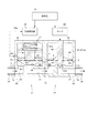
以下、図面を参照して本発明の実施例を説明する。図1は、実施例に係る基板処理装置の概略構成を示すブロック図である。図2は、開閉弁と、流量調整機能を有するサックバック弁を示す縦断面図である。 Hereinafter, embodiments of the present invention will be described with reference to the drawings. FIG. 1 is a block diagram showing a schematic configuration of a substrate processing apparatus according to an embodiment. FIG. 2 is a longitudinal sectional view showing an on-off valve and a suck back valve having a flow rate adjustment function.
<基板処理装置1の構成>
図1を参照する。基板処理装置1は、略水平姿勢で基板Wを保持して回転させる保持回転部2と、処理液を供給する処理液供給部3とを備えている。処理液は、例えばフォトレジスト液の塗布液、現像液、溶剤、または純水等のリンス液が用いられる。処理液供給部3は、本発明の処理液供給装置に相当する。
<Configuration of
Please refer to FIG. The
保持回転部2は、例えば真空吸着により基板Wの裏面を保持するスピンチャック4と、スピンチャック4を略垂直方向の回転軸AX周りに回転させ、モータ等で構成される回転駆動部5とを備えている。保持回転部2の周りには、基板Wの側方を囲うように、上下移動可能なカップ6が設けられている。
The holding and rotating unit 2 includes, for example, a spin chuck 4 for holding the back surface of the substrate W by vacuum suction, and a
処理液供給部3は、基板Wに対して処理液を吐出する吐出ノズル11と、処理液を貯留するタンクなどで構成される処理液供給源13と、処理液供給源13から吐出ノズル11まで処理液を送るための処理液配管15とを備えている。処理液配管15には、処理液供給源13から順番に、ポンプP、開閉弁17および、流量調整機能を有するサックバック弁19が介在されている。なお、処理液配管15には、その他の構成を介在させてもよい。例えば、ポンプPと開閉弁17との間には、フィルタ(図示しない)が介在されてもよい。なお、処理液配管15は、本発明の配管に相当する。
The processing
吐出ノズル11は、ノズル移動機構21により、基板Wの外側の待機ポット23と基板W上方の吐出位置との間で移動される。ノズル移動機構21は、支持アームおよびモータ等で構成されている。なお、吐出ノズル11は、サックバック弁19よりも下流に設けられ、処理液配管15を介在して後述する処理液流路70と接続する。
The
ポンプPは、処理液を吐出ノズル11に送り出すためのものである。開閉弁17は、処理液の供給と処理液の供給停止を行う。サックバック弁19は、開閉弁17の動作と組み合わせることで処理液をサックバック(吸引)し、また、処理液の流量(流速)を調整する。開閉弁17とサックバック弁19は、後で詳細な説明を行う。なお、流量調整機能を有するサックバック弁19は、サックバック機能を有する流量調整弁とも言える。
The pump P is for delivering the treatment liquid to the
処理液供給部3は、中央演算処理装置(CPU)などで構成された制御部31と、基板処理装置1を操作するための操作部33とを備えている。制御部31は、基板処理装置1の各構成を制御する。操作部33は、液晶モニタなどの表示部と、ROM(Read-only Memory)、RAM(Random-Access Memory)、およびハードディスク等の記憶部と、キーボード、マウス、および各種ボタン等の入力部とを備えている。記憶部には、開閉弁17およびサックバック弁19を制御するための条件や、その他、基板処理条件が記憶されている。
The processing
<開閉弁17と、流量調整機能を有するサックバック弁19>
次に、開閉弁17およびサックバック弁19の詳細な構成を説明する。図2を参照する。開閉弁17は、後述する上流側流路43、開閉室内流路50、連結流路51、弁室内流路63、下流側流路67からなる処理液流路70を開閉させる。サックバック弁19は、開閉弁17の動作と組み合わせて、処理液をサックバックし、また、処理液の流量を調整する。
<On-off
Next, detailed configurations of the on-off
〔開閉弁17の構成〕
開閉弁17は、処理液配管15の経路途中に設けられており、上流側流路43、開閉室41、サックバック弁19の弁室61と連通する連結流路51とを直列に連結して構成されている。処理液配管15は、上流側継手部71により開閉室41に取り付けており、開閉弁17の上流側流路43と流路接続している。開閉弁17は、後述するようにその開閉動作によって開閉室41内において、処理液の流れを流通状態と遮断状態とに切り替える。
[Configuration of on-off valve 17]
The on-off
上流側流路43の端部は開閉室41の底部に連通接続されている。なお、処理液配管15の他端部はポンプPに接続されている。よって、ポンプPから送り出された処理液は上流側流路43を通過して開閉室41の開閉室内流路50に流れ込む。
The end of the upstream
開閉室41は中空の箱状部材であり、その内部にはピストン42と、バネ47と、隔壁45と、弁体としてのダイヤフラム46とが設けられている。ピストン42は、開閉室41の内部にて図面の縦方向に沿って摺動自在に構成されている。バネ47は、ピストン42の上面と開閉室41の上部内壁面との間に配置されている。
The open /
隔壁45は開閉室41の内部を上下に仕切る平板状の部材であって、その中央部にはピストン42が貫通している。ピストン42は隔壁45に対して摺動自在ではあるものの、ピストン42と隔壁45との接触部分は完全にシールされており、気体配管48aから開閉室41に空気が送り込まれたときにその空気が隔壁45よりも下側(ダイヤフラム46側)に漏れることはない。
The
ダイヤフラム46の周縁部は開閉室41の内壁面に固設されている。ダイヤフラム46の中央部はピストン42の下端部と固設されている。
The peripheral portion of the
開閉室41の底部中央には第1弁座44が設けられている。連結流路51は、開閉室41の第1弁座44と後述するサックバック弁19の弁室61の弁室内流路63とを連通接続する。
A
開閉室41の側壁には、気体供給部48からの気体を吸気および排気させるための吸排気口49が設けられている。気体供給部48は、制御部31により制御される。気体供給部48は、気体供給源、気体開閉弁およびスピードコントローラ等(いずれも図示しない)で構成される。気体供給部48は、制御部31の制御によって気体配管48aを通じて吸排気口49に気体を供給することができ、また、吸排気口49から気体を排気させてことができる。
On the side wall of the open /
以上のような開閉弁17の構成において、気体供給部48から吸排気口49を介して開閉室41内部に気体が供給されると、ピストン42がバネ47の弾性力に抗して押し上げられた状態(図2の実線で示す状態)となる。ピストン42が押し上げられると、それに固設されたダイヤフラム46が変形されて第1弁座44から離間する。
In the configuration of the on-off
図2の実線で示すように、弁体であるダイヤフラム46が第1弁座44から離間すると、上流側流路43、開閉室内流路50、連結流路51とがそれぞれ連通状態となり、ポンプPから送り出された処理液は上流側流路43から開閉室内流路50、連結流路51、後述する弁室内流路63、下流側流路67を経て吐出ノズル11に到達し、吐出ノズル11から基板Wに向けて処理液が吐出されることとなる。すなわち、図2で示す状態が処理液流路70が開放された処理液が流通する状態である。すなわち、処理液流路70を開閉弁17で開けている状態(開状態)である。
As shown by the solid line in FIG. 2, when the
逆に、気体供給部48から吸排気口49を介して開閉室41内部に気体が排気されると、開閉室41内の圧力が低くなり、バネ47の復元力に抗してピストン42を押し上げる圧力が存在しなくなる。このため、バネ47の復元力によって図2の点線で示すようにピストン42が押し下げられる。ピストン42が押し下げられると、それに固設されたダイヤフラム46が図2の点線で示すように変形されて第1弁座44に密着する。
Conversely, when gas is exhausted from the
図2に示すように、弁体であるダイヤフラム46が第1弁座44に密着すると、開閉室流路50と連結流路51とが遮断された状態となり、ポンプPから送り出された処理液は、連結流路51側へと流れることができず、処理液の流れが停止する。すなわち、処理液流路70を開閉弁17で閉じている状態(閉状態)になる。
As shown in FIG. 2, when the
このように、気体供給部、ピストン42、バネ47等が弁体としてのダイアフラム46を作動させる作動手段として機能するものである。
Thus, the gas supply unit, the
〔流量調整機能を有するサックバック弁19の構成〕
サックバック弁19は、図2のように、開閉弁17よりも下流に設けられている。サックバック弁19は、中空の箱状部材である弁室61と、弁室61内部を図2の上下方向に移動可能に設けられたニードル62と、下流側流路67とを備えている。
[Configuration of suck back
The suck back
弁室61内部には、処理液を流通させる弁室内流路63が設けられている。また、弁室61の底部中央にはニードル62を受ける第2弁座64が設けられており、第2弁座64には、例えば、処理液が流れる開口部64aが設けられている。開口部64aは、下流側流路67と流路接続している。処理液配管15は、下流側継手部72により弁室61に取り付けており、サックバック弁19の下流側流路67と流路接続している。第2弁座64がニードル62を受けると、ニードル62で開口部64aが塞がれる。これにより、弁室内流路63と下流側流路との流路間が閉じられる。
Inside the
また、ニードル62は、弁室内流路63と下流側流路67との間に形成される流路幅(開口部64aの開口具合)、換言すれば処理液流路70流路の絞りを調整するように構成されている。すなわち、ニードル62は、第2弁座64の開口部64aとの隙間を調整することで、その隙間を流れる処理液の流量を調整できるようになっている。
In addition, the
また、サックバック弁19は、ニードル62の先端部に取り付けられたダイアフラム66と、ニードル62を図2の上下方向に駆動させるモータ68とを備えている。ダイアフラム66の周縁部は、弁室61内部の側壁61aに固定されており、ダイアフラム66は、ニードル62の移動方向を横切るように弁室61内部を隔てている。
In addition, the suck back
また、ダイアフラム66は、図2のように、ニードル62と連動する。これにより、ダイアフラム66は、開閉弁17よりも下流の連結流路51から弁室内流路63、下流側流路67までの流路体積を変化させることできる。つまり、ニードル62の移動により、第2弁座64との隙間の調整と、連結流路51から弁室内流路63、下流側流路67までの流路体積の変化が同時に行われる。
Further, the
ニードル62は、本発明の弁体に相当し、ダイアフラム66は、本発明の体積変化部に相当する。モータ68は、本発明の弁体駆動部に相当する。
The
モータ68は、制御部31により、例えばパルス数が与えられて制御される。モータ68の回転は、図示しない機構で変換されて、ニードル62に上下方向の駆動力が与えられる。例えば、制御部31は、開閉弁17が閉状態のときに、モータ68でニードル62と連動するダイアフラム66を移動させて連結流路51から弁室内流路63、下流側流路67までの流路体積を大きくし、サックバックする。また、制御部31は、開閉弁17が開状態のときに、モータ68でニードル62を移動させて処理液の流量を調整する。なお、モータ68には、ニードル62の上下方向の正確な移動量を得られるように、ロータリーエンコーダ等の図示しないセンサが取り付けられていることが好ましい。
The
また、開閉弁17とサックバック弁19は、隣り合わせに配置されている。そのため、開閉弁17とサックバック弁19は、一体的に構成されて、簡易な構成となっている。また、開閉弁17の上流側流路43と、サックバック弁19の下流側流路67と、開閉室内流路50と弁室内流路63とを連結する連結流路51とは、単一部品で構成されてもよい。この場合、例えば、図2の破線Lの下側の開閉室41および弁室61のように、開閉室41の一部と、弁室61の一部とが単一部品で構成されてもよい。
Moreover, the on-off
また、上流側流路43、開閉室内流路50、連結流路51、弁室内流路63および下流側流路67は、処理液を流通させる処理液流路70を形成する。なお、連結流路51、弁室内流路63および下流側流路67は、本発明の下流側処理液流路に相当する。
Further, the upstream
<基板処理装置1の動作>
次に、基板処理装置1の動作のうち、特に、処理液供給部3の動作について説明する。図3は、開閉弁17と流量調整機能を有するサックバック弁19の動作を説明するためのタイミング図である。制御部31は、予め設定された吐出条件(レシピ)に基づき、基板処理装置1の各構成を制御する。
<Operation of
Next, among the operations of the
本発明では、開閉弁17の開閉に応じて、サックバック弁19のモータ68でニードル62を移動させることで、処理液のサックバック(ぼた落ち防止)と流量調整を行っている。この際、サックバックすると流量調整が乱れ、流量調整するとサックバックが乱れる。本発明は、その点を考慮した動作となっている。
In the present invention, the
なお、サックバック弁19において、モータ68でニードル62を昇降させるが、上昇は、ニードル62と第2弁座64とが離れる動作であり、下降は、ニードル62と第2弁座64とが近づく動作である。また、図3および後述する図5において、ニードル62位置が“0”とは、処理液が流通するか否かに関わらず、ニードル62と第2弁座64とが最も接近した位置を示す。
In the suck back
まず、図1の基板処理装置1において、図示しない搬送機構により保持回転部2に基板Wが搬送される。保持回転部2は、基板Wの裏面を保持し、保持した基板Wを回転させる。また、ノズル移動機構21は、基板W外側の待機ポット23から基板W上方の吐出位置に吐出ノズル11を移動させる。制御部31は、開閉弁17およびサックバック弁19を制御して、吐出ノズル11から処理液を吐出する。なお、ポンプPは、駆動されており、開閉弁17が開状態になると、処理液供給源13に貯留された処理液が送り出される。
First, in the
図3の時間t0において、開閉弁17は、開状態であり、吐出ノズル11より処理液が吐出されている。また、開閉弁17が開いている際に、サックバック弁19では、モータ68でニードル62を位置NAに移動させて、位置NAに対応する処理液の流量に調整させている。
At time t0 in FIG. 3, the on-off
制御部31は、吐出ノズル11からの処理液の吐出を停止させる際において、開閉弁17を閉状態にさせる前に、流量を少なくして、より確実にぼた落ちを防止する動作を行う。すなわち、時間t1において、制御部31は、モータ68でニードル62をサックバック基準位置SB0に移動させて、処理液の流量を少なくさせる。その後、時間t2において、制御部31は、処理液流路70の開閉室内流路50と連結流路51間を開閉弁17で閉じ、閉状態にする。
When stopping the discharge of the processing liquid from the
更に、時間t3において、制御部31は、モータ68でニードル62をサックバック実行位置SB1に移動させて、サックバックを行う。言い換えると、制御部31、モータ68でニードル62と連動するダイアフラム66を移動させて、連結流路51から弁室内流路63、下流側流路67までの流路体積を大きくする。これにより、吐出ノズル11の先端内部の処理液がサックバック(吸引)される。なお、時間t2と時間t3は、同じタイミングであってもよい。時間t2が時間t3よりも少々遅れてもよい。また、サックバックは、ニードル62の移動量SDが設定されている。移動量SDは、一定であってもよく、変化させてもよい。
Furthermore, at time t3, the
基板Wへの処理液の吐出が終了し、保持回転部2上の基板Wの入れ替えを行う。すなわち、図1の保持回転部2は、基板Wの回転を停止し、基板Wの保持を解除する。ノズル移動機構21は、吐出ノズル11を基板Wの外側の待機ポット23に移動させる。そして、図示しない搬送機構により、基板Wが入れ替えられる。上述のように、保持回転部2は、基板Wの裏面を保持し、保持した基板Wを回転させる。また、ノズル移動機構21は、基板W外側の待機ポット23から基板W上方の吐出位置に吐出ノズル11を移動させる。
Discharging of the processing liquid onto the substrate W is completed, and the substrate W on the holding and rotating unit 2 is replaced. That is, the holding and rotating unit 2 in FIG. 1 stops the rotation of the substrate W and releases the holding of the substrate W. The
再度、吐出ノズル11から処理液を吐出する。本発明のサックバック弁19の構造上、サックバック動作のためにニードル62が移動する。ニードル62が移動すると、再度の流量調整が必要となる。制御部31は、時間t4において、連結流路51から弁室内流路63、下流側流路67までの流路体積を大きくした状態のニードル62のサックバック実行位置SB1から、予め設定された流量になる位置に、モータ68でニードル62を移動させて、時間t5において、開閉弁17を開ける。
The processing liquid is discharged from the
時間t4の動作について、2つの制御例を説明する。2つの制御例とは、位置NBに上昇させる場合と、位置NCに下降させる場合である。 Two control examples will be described for the operation at time t4. Two control examples are the case of raising to the position NB and the case of lowering to the position NC.
まず、サックバック実行位置SB1から位置NBにニードル62を上昇させる場合について説明する。制御部31は、時間t4において、サックバック実行位置SB1から位置NBに、モータ68でニードル62を上昇させる。ニードル62を上昇させると、ニードル62と連動するダイアフラム66も上昇する。そのため、更にサックバックされることになる。その状態で、時間t5において、制御部31は、処理液流路70を開閉弁17で開けて、吐出ノズル11から処理液を吐出する。処理液流路70を開閉弁17で開ける際に、サックバック実行位置SB1から上昇させるので、吐出ノズル11から処理液が押し出されず、更にサックバックされる。そのため、液だれの心配がない。
First, the case where the
次に、サックバック実行位置SB1から位置NCにニードル62を下降させる場合について説明する。制御部31は、時間t4において、サックバック実行位置SB1から位置NCに、モータ68でニードル62を下降させる。ニードル62を下降させるので、処理液を押し出すことになる。そのため、ニードル62の下降量によっては、吐出ノズル11から処理液が吐出される可能性がある。
Next, the case where the
そこで、制御部31は、予め設定された流量Fとなる位置NCにニードル62を下降させる際に、モータ68により、予め設定された流量Fになるようにニードル62の移動速度を変更する。すなわち、ニードル62の位置NCでの流量Fと同じまたは近づけた流量Fになるように、ニードル62の下降速度(図3の勾配81参照)を調整する。続けて、制御部31は、時間t6において、制御部31は、処理液流路70を開閉弁17で開けて、吐出ノズル11から処理液を吐出する。ニードル62の下降速度を調整し、続けて、開閉弁17を開状態にさせるので、予め設定された流量Fの処理液を連続して自然に流すことができる。
Therefore, when lowering the
所定時間、吐出ノズル11から処理液を吐出した後、上述のように、時間t6において、サックバック弁19のニードル62をサックバック基準位置SB0に下降させて、流量を少なく調整した後、時間t7において、開閉弁17を開状態にさせる。時間t8において、サックバック弁19のニードル62をサックバック実行位置SB1に上昇させて、ニードル62と連動するダイアフラム66を上昇させることで、サックバックさせる。
After the treatment liquid is discharged from the
次に、図4(a)〜図4(c)を参照して、同一基板W内で吐出流量を変更させる場合について説明する。本発明によれば、図3の位置NAと位置NBのように、異なる基板W毎に、または、複数の基板がセットになっている場合はセット毎に、流量調整が容易である。更に、同一基板W内においても流量調整が容易である。 Next, the case where the discharge flow rate is changed in the same substrate W will be described with reference to FIGS. 4 (a) to 4 (c). According to the present invention, it is easy to adjust the flow rate for each different substrate W as in the position NA and the position NB in FIG. 3 or for each set when a plurality of substrates are set. Furthermore, the flow rate adjustment is easy even in the same substrate W.
図4(a)は、基板Wに対する吐出ノズル11の位置を示す図である。そして、図4(b)は、図4(a)の位置関係における吐出量(流量)の一例を示す図である。吐出ノズル11から処理液を吐出しつつ、ノズル移動機構21により、基板Wの中心Cから基板Wの端部Eに吐出ノズル11を移動させる場合がある。この場合、端部Eから例えば50mmの幅に対して、図4(b)のように、吐出量を増やしてもよい。また、必要によっては、減らしてもよい。また、図4(c)のような傾斜で、吐出ノズル11から処理液を吐出させてもよい。
4A shows the position of the
本実施例によれば、処理液流路70を開閉させる開閉弁17よりの下流には、弁室内流路63と下流側流路67との間に形成される流路幅(開口部64aの開口具合)を調整するニードル62と、ニードル62と連動し、開閉弁17よりも下流の連結流路51から弁室内流路63、下流側流路67までの流路体積を変化させるダイアフラム66が設けられている。ニードル62は、モータ68で駆動される。制御部31は、処理液流路70を開閉弁17で閉じている際に、モータ68でニードル62と連動するダイアフラム66を移動させて連結流路51から弁室内流路63、下流側流路67までの流路体積を大きくする。そのため、サックバックでき、処理液のぼた落ちを防止できる。また、制御部31は、処理液流路70を開閉弁17で開いている際に、モータ68でニードル62を移動させて処理液の流量を調整する。そのため、操作者の感覚により調整されていた処理液の流量調整をモータ68によって容易に調整できる。また、同一のモータ68で、処理液のぼた落ち防止と処理液の流量調整ができるので、個別にモータ68等を設ける構成に比べて、構成の無駄を省き、省スペースなものにすることができる。そのため、基板Wごとに異なる流量で処理液を供給でき、また、同一基板Wにおいて、処理液の流量を途中で変えることができる。
According to the present embodiment, the flow passage width formed between the
また、本実施例によれば、開閉弁17は主に開閉に用いられ、サックバック弁19は、詳細な調整が行える構成になっている。そのため、例えば、開閉弁17を簡易なものを選択することができる。
Further, according to the present embodiment, the on-off
また、モータ68は、サックバック弁19のニードル62を駆動するので、複数回に分けて、すなわち多段階にサックバックさせることが容易である。また、流量調整のためのニードル62位置の変えることが容易である。
Further, since the
また、制御部31は、モータ68でニードル62をサックバック基準位置SB0に移動させて処理液の流量を少なくさせた後、処理液流路70を開閉弁17で閉じ、更に、モータ68でニードル62と連動するダイアフラム66を移動させて処理液流路70の体積を大きくする。これにより、処理液流路70を開閉弁17で閉じる際に、処理液の流量が少なくなっているので、処理液の流量が多いことで生じる処理液のぼた落ちを抑えることができる。すなわち、より確実にぼた落ちを防止できる。
Further, the
また、制御部31は、連結流路51から弁室内流路63、下流側流路67までの流路体積を大きくした状態のニードル62の位置から、予め設定された流量になる位置に、モータ68でニードル62を移動させて、処理液流路70を開閉弁17で開ける。サックバックさせるとニードル62の位置が変動するが、処理液流路70を開閉弁17で開けた際に、予め設定された流量の処理液を供給することができる。
In addition, the
また、処理液流路70を開閉弁17で開ける際における、予め設定された流量になる位置へのニードル62の移動は、上昇である。処理液流路70を開閉弁17で開ける際に、ニードル62を上昇させて予め設定された流量するので、処理液が押し出されず、更にサックバックされる。そのため、液だれする心配がない。
In addition, when the processing
また、予め設定された流量となる位置にニードル62を下降させる際に、モータ68により、予め設定された流量になるようにニードル62の下降速度(図3の勾配81参照)を変更する。例えば、予め設定された流量となる位置にニードル62を下降させる際であって、吐出ノズル11より処理液が吐出してしまうときに、ニードル62の下降速度を変更して予め設定された流量で吐出ノズル11より吐出する。これにより、ニードル62移動により吐出する処理液の流量を、処理液流路70を開閉弁17で開けている時の流量に近づけることができる。
Further, when lowering the
また、処理液供給装置3は、ニードル62よりも下流に設けられ、配管を介在して処理液流路70と接続し、処理液を吐出する吐出ノズル11を更に備えている。これにより、吐出ノズル11内に処理液を吸引でき、また、吐出ノズル11から吐出する処理液を流量調整できる。
The treatment
本発明は、上記実施形態に限られることはなく、下記のように変形実施することができる。 The present invention is not limited to the above embodiment, and can be modified as follows.
(1)上述した各実施例では、図3の時間t1のように、開閉弁17を閉状態にさせる前に、サックバック弁19のニードル62をサックバック基準位置SB0に下降させていた。この点、サックバック基準位置SB0に下降させる動作を必要としない場合は、ニードル62を移動させずに、開閉弁17を閉状態にさせてもよい。
(1) In each of the embodiments described above, the
図5の時間t11において、サックバック弁19のニードル62の位置NAを下降せずに、開閉弁17を閉状態にする。時間t12において、予め設定された移動量SDで、ニードル62を位置SB2に上昇させる。すなわち、ニードル62に連動するダイアフラム66を上昇させて、サックバックさせる。基板Wの入れ替えが行われた後、ニードル62を位置NAよりも低い位置NCで、再度、吐出ノズル11から処理液を吐出する。
At time t11 in FIG. 5, the on-off
この場合の動作例を説明する。ノズル移動機構21により、吐出ノズル11を待機ポット23に移動させる。この状態で、時間t13において、ニードル62を位置NCに下降させる。この際、吐出ノズル11から処理液が押し出されても、待機ポット23で回収される。そして、時間t15において、ニードル62を移動量SDで位置SB3に上昇させる。すなわち、ニードル62と連動するダイアフラム66により、サックバックさせる。図5の時間t14〜時間t15の符号83のように、開閉弁17を開状態にさせて、処理液をダミーディスペンスさせてもよい。
An operation example in this case will be described. The
その後、ノズル移動機構21により、待機ポット23から基板W上方へ吐出ノズル11が移動される。時間t16において、ニードル62を下降させて流量調整し、時間t17において、開閉弁17を開状態にさせて吐出ノズル11から処理液を吐出させる。また、時間t18において、開閉弁17を閉状態にさせて吐出ノズル11からの処理液吐出を停止させ、時間t19において、ニードル62に連動するダイアフラム66により、サックバックさせる。
Thereafter, the
また、時間t13において、上述のように、基板W上において、ニードル62の位置NCでの流量Fと同じまたは近づけた流量Fになるように、ニードル62の下降速度(図3、図5の勾配81参照)を調整して、吐出ノズル11から処理液を押し出しつつ、流量調整させてもよい。そして、続けて、開閉弁17を開状態にさせてもよい。
Further, at time t13, as described above, the descent speed of the needle 62 (the slope of FIGS. 3 and 5) such that the flow rate F is the same as or close to the flow rate F at the position NC of the
(2)上述した実施例および変形例(1)では、サックバック弁19の体積変化部として、ダイアフラム66が設けられていた。この点、図6のように、ニードル82には、ニードル82の移動方向を横切るように隔壁82aが設けられ、隔壁82aは、Oリングなどの気密保持部材82bを介在させて、弁室61内部の側壁に接して移動可能であってもよい。
(2) In the embodiment and the modified example (1) described above, the
(3)上述した実施例および各変形例において、例えば処理液として現像液を用いる場合がある。これにより、現像液のぼた落ちを防止し、現像液を流量調整できる。図7のように、制御部31は、ノズル移動機構21により、吐出ノズル11を待機ポット23等に移動させて、純水等が滞留する容器85に吐出ノズル11の先端部を浸す。そして、制御部31は、上流側流路43を閉じている際に、サックバック弁19のモータ68でニードル62と連動するダイアフラム66を往復移動させる。吐出ノズル11の先端部を純水に浸し、純水を吸引させたり、吸引した純水をそのまま一定時間保持したり、吸引した純水を押し出したりすることで、吐出ノズル11先端を洗浄させることができる。図7において、符号86が現像液層であり、符号87が空気などの気体層であり、そして、符号88が純水である。
(3) In the above-described embodiment and each modification, for example, a developing solution may be used as the processing solution. Thus, the developer can be prevented from falling and the flow rate of the developer can be adjusted. As shown in FIG. 7, the
(4)上述した実施例および各変形例では、開閉弁17は、エアオペレートバルブであったが、サックバック弁19のようにモータ駆動であってもよい。また、開閉弁17の弁体は、ダイアフラム46で構成するようにしていたが、サックバック弁19のニードル62のように、流量調整可能であってもよい。また、開閉弁17は、図2のような構成であるが、他の既知の構成であってもよい。
(4) In the above-mentioned embodiment and each modification, although opening and closing
(5)上述した実施例および各変形例では、図3のように、サックバック基準位置SB0は、処理液を流している。必要によっては、サックバック基準位置SB0は、処理液を流通させないようにしてもよい。 (5) In the embodiment and each modification described above, as shown in FIG. 3, the suck back reference position SB0 flows the processing solution. If necessary, the suck back reference position SB0 may not circulate the treatment liquid.
(6)上述した実施例および各変形例では、サックバック弁19の内の各流路は、単一部品で構成されていたが、個別の部品であってもよい。すなわち、開閉弁17とサックバック弁19とが個別に構成される。この場合、開閉弁17とサックバック弁19は、処理液配管15を介在して接続される。
(6) In the above-mentioned embodiment and each modification, each channel in suck back
1 … 基板処理装置
3 … 処理液供給部
11 … 吐出ノズル
15 … 処理液配管
17 … 開閉弁
19 … サックバック弁
31 … 制御部
43 … 上流側流路
50 … 開閉室内流路
51 … 連結流路
62,82 … ニードル
63 … 弁室内流路
66 … ダイアフラム
67 … 下流側流路
68 … モータ
70 … 処理液流路
81 … 勾配
t1〜t8,t11〜t19 … 時間
DESCRIPTION OF
Claims (11)
前記処理液流路を開閉させる開閉弁と、
前記開閉弁よりも下流の下流側処理液流路に設けられ、処理液を流通させる開口部を有する弁座と、
前記開閉弁よりも下流に設けられ、前記開口部に通して前記開口部との隙間を調整することで前記処理液流路の絞りを調整するニードルと、
前記開閉弁よりも下流に設けられ、前記ニードルの先端部が突出するように前記ニードルに取り付けられることで前記ニードルと連動し、前記下流側処理液流路の体積を変化させるダイアフラムと、
前記ニードルを駆動させる弁体駆動部と、
前記処理液流路を前記開閉弁で閉じている際に、前記弁体駆動部で前記ニードルと連動する前記ダイアフラムを移動させて前記下流側処理液流路の体積を大きくし、前記処理液流路を前記開閉弁で開いている際に、前記弁体駆動部で前記ニードルを移動させて前記処理液の流量を調整する制御部と、
を備えることを特徴とする処理液供給装置。 A treatment liquid flow path for circulating the treatment liquid;
An on-off valve for opening and closing the processing liquid flow path;
A valve seat provided in a downstream processing liquid flow path downstream of the on-off valve and having an opening through which the processing liquid flows;
A needle which is provided downstream of the on-off valve, and adjusts the throttling of the processing liquid flow path by adjusting a gap with the opening through the opening ;
Provided downstream from the on-off valve, the tip of the needle in conjunction with the needle by being attached to the needle so as to protrude, a diaphragm for changing the volume of the downstream treatment liquid flow path,
A valve body drive unit for driving the needle ;
When the processing liquid flow path is closed by the on-off valve, the valve body driving unit moves the diaphragm interlocking with the needle to increase the volume of the downstream processing liquid flow path, and the processing liquid flow A control unit for moving the needle by the valve body drive unit to adjust the flow rate of the processing liquid when the passage is opened by the on-off valve;
A processing liquid supply apparatus comprising:
前記弁体駆動部は、モータであることを特徴とする処理液供給装置。 In the processing liquid supply apparatus according to claim 1,
The said valve body drive part is a motor, The processing liquid supply apparatus characterized by the above-mentioned.
前記制御部は、前記弁体駆動部で前記ニードルをサックバック基準位置に移動させて前記処理液の流量を少なくさせた後、前記処理液流路を前記開閉弁で閉じ、更に、前記弁体駆動部で前記ニードルと連動する前記ダイアフラムを移動させて前記処理液流路の体積を大きくすることを特徴とする処理液供給装置。 In the processing liquid supply apparatus according to claim 1 or 2,
The control unit moves the needle to the suck back reference position by the valve drive unit to reduce the flow rate of the processing liquid, and then closes the processing liquid flow path with the on-off valve, and further, the valve A processing liquid supply apparatus characterized by moving the diaphragm interlocked with the needle by a drive unit to increase the volume of the processing liquid flow path.
前記制御部は、前記下流側処理液流路の体積を大きくした状態の前記ニードルの位置から、予め設定された流量になる位置に、前記弁体駆動部で前記ニードルを移動させて、前記処理液流路を前記開閉弁で開けることを特徴とする処理液供給装置。 In the processing liquid supply apparatus according to any one of claims 1 to 3,
The control unit causes the valve drive unit to move the needle from the position of the needle in a state in which the volume of the downstream processing liquid flow path is increased to a position at which the flow rate is set in advance. A processing liquid supply apparatus characterized in that a liquid flow path is opened by the on-off valve.
前記処理液流路を開閉させる開閉弁と、
前記開閉弁よりも下流に設けられ、前記処理液流路の絞りを調整する弁体と、
前記開閉弁よりも下流に設けられ、前記弁体と連動し、前記開閉弁よりも下流の下流側処理液流路の体積を変化させる体積変化部と、
前記弁体を駆動させる弁体駆動部と、
前記処理液流路を前記開閉弁で閉じている際に、前記弁体駆動部で前記弁体と連動する前記体積変化部を移動させて前記下流側処理液流路の体積を大きくし、前記処理液流路を前記開閉弁で開いている際に、前記弁体駆動部で前記弁体を移動させて前記処理液の流量を調整する制御部と、を備え、
前記制御部は、前記下流側処理液流路の体積を大きくした状態の前記弁体の位置から予め設定された流量になる位置に、前記弁体駆動部で前記弁体を移動させて、更に、前記下流側処理液流路の体積を大きくし、前記処理液流路を前記開閉弁で開けることを特徴とする処理液供給装置。 A treatment liquid flow path for circulating the treatment liquid;
An on-off valve for opening and closing the processing liquid flow path;
A valve body provided downstream of the on-off valve for adjusting the throttling of the processing liquid flow path;
A volume change unit provided downstream of the on-off valve, interlocking with the valve body, and changing a volume of a downstream process liquid flow passage downstream of the on-off valve;
A valve body drive unit for driving the valve body;
When the processing liquid flow path is closed by the on-off valve, the volume change portion interlocked with the valve body is moved by the valve body driving portion to increase the volume of the downstream processing liquid flow path, and And a control unit configured to move the valve body by the valve body drive unit to adjust the flow rate of the process liquid when the process liquid flow path is opened by the on-off valve.
The control unit causes the valve body drive unit to move the valve body to a position at which the flow rate is preset from the position of the valve body in a state in which the volume of the downstream process liquid flow path is increased. A processing liquid supply apparatus , wherein the volume of the downstream processing liquid flow path is increased, and the processing liquid flow path is opened by the on-off valve .
予め設定された流量となる位置に前記ニードルを下降させる際に、前記弁体駆動部により、前記予め設定された流量になるように前記ニードルの下降速度を変更することを特徴とする処理液供給装置。 In the processing liquid supply apparatus according to claim 4,
When lowering the needle to a position at which the flow rate is set in advance, the valve body driving unit changes the lowering speed of the needle so as to achieve the flow rate set in advance. apparatus.
前記処理液流路は、単一部品で構成されていることを特徴とする処理液供給装置。 The treatment liquid supply apparatus according to any one of claims 1 to 6.
The processing liquid supply device, wherein the processing liquid flow path is constituted by a single component.
前記ニードルよりも下流に設けられ、配管を介在して前記処理液流路と接続し、前記処理液を吐出する吐出ノズルを更に備えていることを特徴とする処理液供給装置。 The treatment liquid supply apparatus according to any one of claims 1 to 4 ,
A processing liquid supply apparatus, further comprising: a discharge nozzle provided downstream of the needle, connected to the processing liquid flow path through a pipe, and discharging the processing liquid.
前記処理液は、現像液であることを特徴とする処理液供給装置。 The processing liquid supply apparatus according to any one of claims 1 to 8.
The processing liquid supply device, wherein the processing liquid is a developer.
前記制御部は、前記処理液流路を前記開閉弁で閉じている際に、前記弁体駆動部で前記ニードルと連動する前記ダイアフラムを往復移動させることを特徴とする処理液供給装置。
The processing liquid supply apparatus according to any one of claims 1 to 4 , 6 and 8 .
The said control part makes the said reciprocating movement of the said diaphragm interlocked | cooperated with the needle in the said valve body drive part, when closing the said process liquid flow path with the said on-off valve.
前記処理液流路を開閉させる開閉弁と、
前記開閉弁よりも下流に設けられ、前記処理液流路の絞りを調整する弁体と、
前記開閉弁よりも下流に設けられ、前記開閉弁よりも下流の下流側処理液流路の体積を変化させる体積変化部と、
前記弁体を駆動させる弁体駆動部と、
前記弁体よりも下流に設けられ、配管を介在して前記処理液流路と接続し、前記処理液を吐出する吐出ノズルと、
を備えることを特徴とする処理液供給装置の制御方法であって、
前記処理液流路を前記開閉弁で閉じている際に、前記弁体駆動部で前記弁体と連動する前記体積変化部を移動させて前記下流側処理液流路の体積を大きくする工程と、前記処理液流路を前記開閉弁で開いている際に、前記弁体駆動部で前記弁体を移動させて前記処理液の流量を調整する工程と、
容器に入っている液体に前記吐出ノズルの先端部を浸す工程と、
前記吐出ノズルの先端部を前記液体に浸した状態でかつ、前記処理液流路を前記開閉弁で閉じている際に、前記弁体駆動部で前記弁体と連動する前記体積変化部を往復移動させる工程と、
を備えることを特徴とする処理液供給装置の制御方法。 A treatment liquid flow path for circulating the treatment liquid;
An on-off valve for opening and closing the processing liquid flow path;
A valve body provided downstream of the on-off valve for adjusting the throttling of the processing liquid flow path;
A volume change unit provided downstream of the on-off valve and changing a volume of a downstream process liquid flow path downstream of the on-off valve;
A valve body drive unit for driving the valve body;
A discharge nozzle provided downstream of the valve body, connected to the processing liquid flow path through a pipe, and discharging the processing liquid;
A control method of a processing liquid supply apparatus comprising:
A step of moving the volume change unit interlocked with the valve body by the valve body driving unit to increase the volume of the downstream process liquid flow path when the treatment liquid flow path is closed by the on-off valve; And adjusting the flow rate of the processing liquid by moving the valve body by the valve body driving unit when the processing liquid flow path is opened by the on-off valve.
Immersing the tip of the discharge nozzle in the liquid contained in the container;
In a state in which the tip portion of the discharge nozzle is immersed in the liquid, and the processing liquid flow path is closed by the on-off valve, the valve body driving portion reciprocates the volume changing portion interlocked with the valve body A process of moving
And a control method of the processing liquid supply device.
Priority Applications (5)
| Application Number | Priority Date | Filing Date | Title |
|---|---|---|---|
| JP2015066617A JP6512894B2 (en) | 2015-03-27 | 2015-03-27 | Treatment liquid supply apparatus and control method of treatment liquid supply apparatus |
| PCT/JP2016/054174 WO2016158032A1 (en) | 2015-03-27 | 2016-02-12 | Treatment liquid supply device and method of controlling treatment liquid supply device |
| US15/556,517 US20180046083A1 (en) | 2015-03-27 | 2016-02-12 | Processing liquid supplying apparatus and method of controlling processing liquid supplying apparatus |
| KR1020177025980A KR102053510B1 (en) | 2015-03-27 | 2016-02-12 | Process liquid supply device and process liquid supply device control method |
| TW105107885A TWI609721B (en) | 2015-03-27 | 2016-03-15 | Treatment liquid supplying apparatus and controlling method of treatment liquid supplying apparatus |
Applications Claiming Priority (1)
| Application Number | Priority Date | Filing Date | Title |
|---|---|---|---|
| JP2015066617A JP6512894B2 (en) | 2015-03-27 | 2015-03-27 | Treatment liquid supply apparatus and control method of treatment liquid supply apparatus |
Publications (2)
| Publication Number | Publication Date |
|---|---|
| JP2016187000A JP2016187000A (en) | 2016-10-27 |
| JP6512894B2 true JP6512894B2 (en) | 2019-05-15 |
Family
ID=57005732
Family Applications (1)
| Application Number | Title | Priority Date | Filing Date |
|---|---|---|---|
| JP2015066617A Active JP6512894B2 (en) | 2015-03-27 | 2015-03-27 | Treatment liquid supply apparatus and control method of treatment liquid supply apparatus |
Country Status (5)
| Country | Link |
|---|---|
| US (1) | US20180046083A1 (en) |
| JP (1) | JP6512894B2 (en) |
| KR (1) | KR102053510B1 (en) |
| TW (1) | TWI609721B (en) |
| WO (1) | WO2016158032A1 (en) |
Families Citing this family (13)
| Publication number | Priority date | Publication date | Assignee | Title |
|---|---|---|---|---|
| JP6753764B2 (en) * | 2016-11-21 | 2020-09-09 | 株式会社Screenホールディングス | Valve unit and board processing equipment |
| JP6932000B2 (en) * | 2017-02-08 | 2021-09-08 | 株式会社Screenホールディングス | Board processing device, control method and program of board processing device |
| JP6925872B2 (en) * | 2017-05-31 | 2021-08-25 | 東京エレクトロン株式会社 | Substrate liquid processing equipment, processing liquid supply method and storage medium |
| JP7029314B2 (en) * | 2018-03-07 | 2022-03-03 | 株式会社Screenホールディングス | Chemical control valve and substrate processing equipment |
| JP6980597B2 (en) * | 2018-05-11 | 2021-12-15 | 株式会社Screenホールディングス | Processing liquid discharge method and processing liquid discharge device |
| KR102081707B1 (en) * | 2018-09-21 | 2020-02-27 | 세메스 주식회사 | Valve unit and liquid supplying unit |
| MX2021003525A (en) * | 2018-09-25 | 2022-09-21 | Honda Motor Co Ltd | Delivery device, mold using same, and delivery method. |
| JP7223609B2 (en) * | 2019-03-20 | 2023-02-16 | 株式会社Screenホールディングス | Treatment liquid supply device and method of controlling treatment liquid supply device |
| KR102174254B1 (en) * | 2020-02-27 | 2020-11-04 | (주)에스티아이 | Manifold assembly and chemical sampling apparatus having the same |
| KR102355356B1 (en) * | 2020-03-25 | 2022-01-25 | 무진전자 주식회사 | Chemical providing management system of semiconductor process |
| KR102677969B1 (en) * | 2020-12-30 | 2024-06-26 | 세메스 주식회사 | Nozzel standby port, apparatus for treating substrate including the same and method for treating substrate using the same |
| JP7628434B2 (en) * | 2021-02-15 | 2025-02-10 | 株式会社Screenホールディングス | Substrate processing apparatus and method for processing cylindrical guard |
| JP2023117145A (en) * | 2022-02-10 | 2023-08-23 | 株式会社Screenホールディングス | Processing liquid supply method and substrate processing apparatus |
Family Cites Families (16)
| Publication number | Priority date | Publication date | Assignee | Title |
|---|---|---|---|---|
| JPS5442232A (en) | 1977-09-09 | 1979-04-04 | Uben Ootomo | Machine for experimenting on horse racing and bike race |
| JP3329720B2 (en) * | 1998-01-19 | 2002-09-30 | 東京エレクトロン株式会社 | Coating device |
| JP3993496B2 (en) * | 2001-09-27 | 2007-10-17 | 東京エレクトロン株式会社 | Substrate processing method and coating processing apparatus |
| JP3983742B2 (en) * | 2003-02-28 | 2007-09-26 | 三菱製紙株式会社 | Photosensitive material processing equipment |
| JP3920831B2 (en) * | 2003-09-29 | 2007-05-30 | 東京エレクトロン株式会社 | Coating film removing apparatus and coating film removing method |
| US7275879B2 (en) * | 2004-02-23 | 2007-10-02 | Mitsubishi Paper Mills Limited | Processing device of photo-sensitive material |
| JP4237781B2 (en) * | 2006-06-29 | 2009-03-11 | シーケーディ株式会社 | Flow control valve |
| KR100781457B1 (en) * | 2006-08-28 | 2007-12-03 | 동부일렉트로닉스 주식회사 | Developer Leak Detection System in Semiconductor Developer |
| JP2010103131A (en) * | 2008-10-21 | 2010-05-06 | Tokyo Electron Ltd | Apparatus and method for treating liquid |
| JP4948584B2 (en) * | 2009-10-19 | 2012-06-06 | 日立造船株式会社 | Emergency stop control method for rotary filling equipment and rotary filling equipment |
| JP5269130B2 (en) * | 2011-03-14 | 2013-08-21 | 東京エレクトロン株式会社 | Substrate processing apparatus and processing liquid supply method |
| JP5127080B2 (en) * | 2011-06-21 | 2013-01-23 | 東京エレクトロン株式会社 | Liquid processing equipment |
| JP2013071026A (en) * | 2011-09-26 | 2013-04-22 | Toshiba Corp | Coating apparatus and coating method |
| JP5853971B2 (en) * | 2013-03-01 | 2016-02-09 | 東京エレクトロン株式会社 | Liquid supply device |
| JP6180267B2 (en) * | 2013-09-30 | 2017-08-16 | Ckd株式会社 | Fluid-driven shut-off valve |
| JP6319117B2 (en) * | 2015-01-26 | 2018-05-09 | 東京エレクトロン株式会社 | Treatment liquid supply apparatus, treatment liquid supply method, and storage medium |
-
2015
- 2015-03-27 JP JP2015066617A patent/JP6512894B2/en active Active
-
2016
- 2016-02-12 US US15/556,517 patent/US20180046083A1/en not_active Abandoned
- 2016-02-12 KR KR1020177025980A patent/KR102053510B1/en active IP Right Grant
- 2016-02-12 WO PCT/JP2016/054174 patent/WO2016158032A1/en active Application Filing
- 2016-03-15 TW TW105107885A patent/TWI609721B/en active
Also Published As
| Publication number | Publication date |
|---|---|
| TWI609721B (en) | 2018-01-01 |
| US20180046083A1 (en) | 2018-02-15 |
| TW201641161A (en) | 2016-12-01 |
| KR20170116155A (en) | 2017-10-18 |
| WO2016158032A1 (en) | 2016-10-06 |
| KR102053510B1 (en) | 2020-01-08 |
| JP2016187000A (en) | 2016-10-27 |
Similar Documents
| Publication | Publication Date | Title |
|---|---|---|
| JP6512894B2 (en) | Treatment liquid supply apparatus and control method of treatment liquid supply apparatus | |
| KR101972675B1 (en) | Coating device | |
| US7767026B2 (en) | Substrate processing apparatus and substrate processing method | |
| JP5566829B2 (en) | Liquid automatic supply mechanism and coating apparatus provided with the same | |
| JP6041421B2 (en) | Liquid material discharge mechanism and liquid material discharge device | |
| JP6576217B2 (en) | Treatment liquid supply apparatus and control method of treatment liquid supply apparatus | |
| TWI645450B (en) | Treatment liquid supply device, treatment liquid supply method and recording medium | |
| KR102328464B1 (en) | Substrate processing method and substrate processing apparatus | |
| KR101998894B1 (en) | Liquid supplying apparatus | |
| KR20190086348A (en) | Treatment liquid supply device and deairing method thereof | |
| KR102627121B1 (en) | Nozzle waiting apparatus, liquid processing apparatus and method for operating liquid processing apparatus and storage medium | |
| KR102585104B1 (en) | Apparatus for treating substrate using liquid and method for cotrolling liquid | |
| US11000783B2 (en) | Pumping apparatus, treatment solution supplying device, and substrate treating apparatus | |
| JP2017051885A (en) | Coating device | |
| KR20210028787A (en) | Unit for supplying liquid and apparatus and method for treating a substrate with the unit | |
| WO2022014329A1 (en) | Liquid treatment device, liquid supply mechanism, liquid treatment method, and computer storage medium | |
| JP2013202609A (en) | Coating liquid coating apparatus | |
| JP2020181901A (en) | Operation method of liquid treatment device and liquid treatment device | |
| WO2019004390A1 (en) | Substrate processing device and substrate processing method | |
| KR20070014526A (en) | Coating Liquid Nozzle Arm Structure of Semiconductor Manufacturing Equipment |
Legal Events
| Date | Code | Title | Description |
|---|---|---|---|
| A621 | Written request for application examination |
Free format text: JAPANESE INTERMEDIATE CODE: A621 Effective date: 20171222 |
|
| A131 | Notification of reasons for refusal |
Free format text: JAPANESE INTERMEDIATE CODE: A131 Effective date: 20181023 |
|
| A521 | Request for written amendment filed |
Free format text: JAPANESE INTERMEDIATE CODE: A523 Effective date: 20181219 |
|
| A131 | Notification of reasons for refusal |
Free format text: JAPANESE INTERMEDIATE CODE: A131 Effective date: 20190205 |
|
| A521 | Request for written amendment filed |
Free format text: JAPANESE INTERMEDIATE CODE: A523 Effective date: 20190312 |
|
| TRDD | Decision of grant or rejection written | ||
| A01 | Written decision to grant a patent or to grant a registration (utility model) |
Free format text: JAPANESE INTERMEDIATE CODE: A01 Effective date: 20190326 |
|
| A61 | First payment of annual fees (during grant procedure) |
Free format text: JAPANESE INTERMEDIATE CODE: A61 Effective date: 20190409 |
|
| R150 | Certificate of patent or registration of utility model |
Ref document number: 6512894 Country of ref document: JP Free format text: JAPANESE INTERMEDIATE CODE: R150 |
|
| R250 | Receipt of annual fees |
Free format text: JAPANESE INTERMEDIATE CODE: R250 |
|
| R250 | Receipt of annual fees |
Free format text: JAPANESE INTERMEDIATE CODE: R250 |
|
| R250 | Receipt of annual fees |
Free format text: JAPANESE INTERMEDIATE CODE: R250 |