[go: up one dir, main page]

JP6503854B2 - Tractor - Google Patents

Tractor Download PDF

Info

Publication number
JP6503854B2
JP6503854B2 JP2015080080A JP2015080080A JP6503854B2 JP 6503854 B2 JP6503854 B2 JP 6503854B2 JP 2015080080 A JP2015080080 A JP 2015080080A JP 2015080080 A JP2015080080 A JP 2015080080A JP 6503854 B2 JP6503854 B2 JP 6503854B2
Authority
JP
Japan
Prior art keywords
clutch
brake
pressure
gear
speed
Prior art date
Legal status (The legal status is an assumption and is not a legal conclusion. Google has not performed a legal analysis and makes no representation as to the accuracy of the status listed.)
Active
Application number
JP2015080080A
Other languages
Japanese (ja)
Other versions
JP2016200203A (en
Inventor
小野 弘喜
弘喜 小野
Current Assignee (The listed assignees may be inaccurate. Google has not performed a legal analysis and makes no representation or warranty as to the accuracy of the list.)
Iseki and Co Ltd
Original Assignee
Iseki and Co Ltd
Priority date (The priority date is an assumption and is not a legal conclusion. Google has not performed a legal analysis and makes no representation as to the accuracy of the date listed.)
Filing date
Publication date
Application filed by Iseki and Co Ltd filed Critical Iseki and Co Ltd
Priority to JP2015080080A priority Critical patent/JP6503854B2/en
Publication of JP2016200203A publication Critical patent/JP2016200203A/en
Application granted granted Critical
Publication of JP6503854B2 publication Critical patent/JP6503854B2/en
Active legal-status Critical Current
Anticipated expiration legal-status Critical

Links

Images

Landscapes

  • Braking Elements And Transmission Devices (AREA)
  • Hydraulic Clutches, Magnetic Clutches, Fluid Clutches, And Fluid Joints (AREA)

Description

本発明は、農業機械であるトラクタに関し、特にトラクタにおける制動制御装置に関する。   The present invention relates to a tractor that is an agricultural machine, and more particularly to a braking control device in a tractor.

トラクタは、エンジンの動力を前輪及び後輪等の走行装置に伝動するために、動力伝動装置内に複数のクラッチと変速装置等を設けている。そして、機体にはアクセルペダル、ブレーキペダル、クラッチペダルを設けている。走行停止の際にブレーキペダルを踏んでブレーキを効かせると共に、クラッチペダルを踏んでクラッチを切る操作を行うのが普通である。しかしながら、走行と停止を頻繁に行う走行中には、クラッチの切操作とブレーキ操作を頻繁に行うのが面倒であるので、ブレーキ操作だけで自動的にクラッチを切って機体を停止させ、ブレーキペダルを開放してブレーキを解除するだけで自動的にクラッチを入り状態にして走行できるようにすることが行われる。   The tractor is provided with a plurality of clutches, a transmission, and the like in the power transmission device to transmit the power of the engine to the travel devices such as the front wheels and the rear wheels. The machine body is provided with an accelerator pedal, a brake pedal, and a clutch pedal. When stopping traveling, it is usual to depress the brake pedal to apply the brake and to depress the clutch pedal to disengage the clutch. However, while traveling and stopping frequently, it is troublesome to frequently perform the operation of releasing the clutch and the operation of braking. Therefore, the clutch is automatically disconnected and the machine is stopped only by the operation of the brake, and the brake pedal By simply releasing the brake and releasing the brake, it is possible to automatically put the clutch in the on state to enable traveling.

例えば、下記特許文献1には、左右の走行ブレーキのアームと左右のブレーキペダルのアームとを連結するロッドにロードセルを介在させて、左右のブレーキペダルの踏み込み操作時の踏力をロードセルで検出し、主クラッチの作動圧力を制御する構成が開示されている。本構成により、ブレーキペダルの踏み込み操作のみで走行ブレーキと主クラッチの両方の動作を行い、半クラッチ状態も容易に可能とし、また主クラッチペダルを同時に操作することなくブレーキペダルの操作のみで主クラッチを切りにできる。   For example, in Patent Document 1 below, a load cell is interposed in a rod connecting the left and right travel brake arms and the left and right brake pedal arms, and the load cell is detected by the load cell when the left and right brake pedals are depressed. An arrangement is disclosed to control the operating pressure of the main clutch. With this configuration, both the traveling brake and the main clutch can be operated only by stepping on the brake pedal, and the half clutch state can be easily enabled, and the main clutch can be operated only by operating the brake pedal without simultaneously operating the main clutch pedal. You can cut

特許第3907464号公報Patent No. 3907464

前記特許文献1に記載のトラクタでは、走行車速に応じてブレーキ踏力とクラッチ作動圧力との関係が選択され、ブレーキ踏力が大きい場合はクラッチ作動圧力を低めにするため、そのブレーキ踏力の変化速度によっては急ブレーキとなる。   In the tractor described in Patent Document 1, the relationship between the brake depression force and the clutch actuation pressure is selected according to the traveling vehicle speed, and when the brake depression force is large, the clutch actuation pressure is lowered. Is a sudden brake.

また、ブレーキ踏力が同じでも車速が変化するとクラッチ作動圧力が変化するので、状況により急にブレーキ力が強くなることがある。急ブレーキ操作によりブレーキは急制動し、また主クラッチは完全に切りとなるため、エンジンブレーキを有効利用できなくなる。即ち、クラッチ作動圧力がゼロとなり、ブレーキを踏んだ時点での車速にもよるが、完全に停車していない状態でクラッチが切れる場合もあり、このときにはエンジンとの連結がされていないため、エンジンブレーキの作用はゼロとなる。   Further, even if the brake depression force is the same, if the vehicle speed changes, the clutch operating pressure changes, so the braking force may suddenly increase depending on the situation. The sudden braking operation causes the brake to be sharply braked and the main clutch to be completely disengaged, so that the engine brake can not be used effectively. That is, although the clutch operating pressure is zero and it depends on the vehicle speed at the time of stepping on the brake, the clutch may be disengaged in a state where the vehicle is not completely stopped. At this time, the engine is not connected. The action of the brake is zero.

そこで、本発明の課題は、ブレーキ操作だけで速やかにトラクタを停車させることである。   Then, the subject of this invention is to stop a tractor quickly only by brake operation.

本発明の上記課題は次の解決手段により解決される。
請求項1記載の発明は、エンジン(5)と、エンジン(5)の動力により駆動する走行装置(2,3)と、エンジン(5)と走行装置(2,3)との間の動力伝動経路に設けられ、前後進と中立を切り替える前後進クラッチ(48)と、走行装置(2,3)に設けたブレーキ(135)と、踏み込み操作によりブレーキ(135)を作動させるブレーキペダル(19)と、ブレーキペダル(19)の足載せ部(19a)に設けられ、該足載せ部(19a)に掛かる圧力を検出するブレーキペダル踏力検出手段(160)と、ブレーキペダル踏力検出手段(160)により規定以上の踏力が検出されると、前後進クラッチ(48)の接続作動圧を規定の圧力に低下させるクラッチ圧低下機能を有する制御装置(120)とを設けたトラクタである。
The above-mentioned subject of the present invention is solved by the following solution means.
The invention according to claim 1 comprises an engine (5), a traveling device (2, 3) driven by the power of the engine (5), and a power transmission between the engine (5) and the traveling device (2, 3) A forward and reverse clutch (48) provided on the route to switch between forward and reverse and neutral, a brake (135) provided on the traveling device (2, 3), and a brake pedal (19) operating the brake (135) by stepping And brake pedal depression force detection means (160) provided in the footrest portion (19a) of the brake pedal (19) to detect the pressure applied to the footrest portion (19a), and the brake pedal depression force detection means (160) It is a tractor provided with a control device (120) having a clutch pressure lowering function to reduce the connection operating pressure of the forward / reverse clutch (48) to a prescribed pressure when a pedaling force above a prescribed level is detected. .

請求項2記載の発明は、ブレーキペダル(19)の操作位置からブレーキ(135)の入切操作を検出するブレーキ操作検出手段(123又は163)を設け、前記制御装置(120)は、ブレーキ操作検出手段(123又は163)によってブレーキ(135)の入り操作が検出されると、前記クラッチ圧低下機能を有効とするクラッチ圧低下有効機能を有する請求項1に記載のトラクタである。   The invention according to claim 2 is provided with a brake operation detection means (123 or 163) for detecting the on / off operation of the brake (135) from the operation position of the brake pedal (19), and the control device (120) performs the brake operation. The tractor according to claim 1, further comprising: a clutch pressure reduction effective function that makes the clutch pressure reduction function effective when the detecting means (123 or 163) detects that the brake (135) is depressed.

請求項3記載の発明は、前後進クラッチ(48)と走行装置(2,3)との間の動力伝動経路に、エンジン(5)の動力を変速する変速装置(150,154)を設け、変速装置(150,154)を複数の変速段に操作する変速操作手段(14,15)と、該変速操作手段(14,15)の操作位置を検出する変速操作位置検出手段(134,171)を設け、前記クラッチ圧低下機能の規定の圧力は変速段毎に設定されており、前記制御装置(120)は、変速操作位置検出手段(134,171)により検出される操作位置の変速段に対応する規定の圧力に前後進クラッチ(48)の接続作動圧を低下させるクラッチ圧変速段低下機能を有する請求項1又は請求項2に記載のトラクタである。   The invention according to claim 3 provides a transmission (150, 154) for shifting the power of the engine (5) in the power transmission path between the forward and reverse clutch (48) and the traveling device (2, 3), Shift operation means (14, 15) for operating the transmission (150, 154) to a plurality of shift speeds, and shift operation position detection means (134, 171) for detecting the operation position of the shift operation means (14, 15) The specified pressure of the clutch pressure reduction function is set for each shift speed, and the control device (120) is set to the shift position of the operation position detected by the shift operation position detection means (134, 171). The tractor according to claim 1 or 2, further comprising: a clutch pressure shift stage reducing function of reducing the connection operating pressure of the forward and reverse clutch (48) to a corresponding prescribed pressure.

請求項1記載の発明によれば、足載せ部(19a)に設けたブレーキペダル踏力検出手段(160)によってブレーキペダル(19)の規定以上の操作力による踏み込みを検出するため、ブレーキ操作していること自体、即ち作業者が意図的にブレーキ操作していることを検出でき、低圧状態の作動圧力とする制御が確実にでき、急制動になることがない。そして、ブレーキペダル(19)が間違いなく踏まれたときにクラッチ圧低下機能を作動させるので、ブレーキ作動と低圧状態への作用を同期させることができる。   According to the first aspect of the present invention, the brake pedal depression force detection means (160) provided in the footrest (19a) detects the depression by the operation force more than the specified value of the brake pedal (19). Therefore, it is possible to detect that the driver is intentionally braking the driver, and to control the operating pressure to a low pressure state reliably, without sudden braking. And since a clutch pressure fall function is operated when a brake pedal (19) is stepped on certainly, the action | operation to a brake application and a low voltage | pressure state can be synchronized.

請求項2記載の発明によれば、請求項1に記載の発明の効果に加えて、ブレーキ(135)の入り操作も低圧状態の作動圧力とするための条件とすることで、ブレーキペダル(19)の踏み込み操作の検出がより確実になる。   According to the second aspect of the present invention, in addition to the effects of the first aspect of the present invention, the brake pedal (19 The detection of the stepping operation of) is more reliable.

請求項3記載の発明によれば、請求項1又は請求項2に記載の発明の効果に加えて、半クラッチの作動圧力を変速操作手段(14,15)の変速段に応じて変えることで、走行停止の際には低圧時の規定のトルクによる駆動とブレーキ制動力により急停車をすることなく停止できる。また、再発進時に速やかに走行を再開できる。   According to the third aspect of the invention, in addition to the effects of the first or second aspect of the invention, the operating pressure of the half clutch is changed according to the shift speed of the shift operating means (14, 15). When traveling is stopped, the vehicle can be stopped without sudden stop by driving with a prescribed torque at low pressure and the braking force. In addition, traveling can be resumed promptly upon re-starting.

図1(A)は本実施形態のトラクタの全体側面図であり、図1(B)はブレーキペダルとアクセルペダル部分の平面図である。FIG. 1 (A) is an overall side view of the tractor according to the present embodiment, and FIG. 1 (B) is a plan view of a brake pedal and an accelerator pedal. エンジンから前後輪及びPTO軸への動力伝動線図である。FIG. 5 is a power transmission line diagram from an engine to front and rear wheels and a PTO shaft. ミッションケースの断面展開図である。It is a cross-sectional expanded view of a mission case. ミッションケースの正断面図である。It is a front sectional view of a mission case. ミッションケースの断面斜視図である。It is a cross-sectional perspective view of a transmission case. フロントパネルの正面図である。It is a front view of a front panel. ステアリングハンドルの左側部斜視図である。It is a left side perspective view of a steering wheel. トラクタの自動制御ブロック図である。It is an automatic control block diagram of a tractor. 左ブレーキペダルの側面図である。It is a side view of a left brake pedal. 本実施形態のトラクタの制動制御のフローチャートの一例である。It is an example of the flowchart of the braking control of the tractor of this embodiment. 本実施形態のトラクタの制動制御のフローチャートの他の例である。It is another example of the flowchart of the braking control of the tractor of this embodiment. 図12(A)はブレーキペダルの踏み込み操作に伴うブレーキ操作位置センサの電圧とブレーキ操作力センサの電圧との関係を示した図であり、図12(B)はブレーキペダル操作とクラッチ圧力との関係を示した図である。FIG. 12A is a diagram showing the relationship between the voltage of the brake operation position sensor and the voltage of the brake operation force sensor accompanying the stepping operation of the brake pedal, and FIG. 12B shows the relationship between the brake pedal operation and the clutch pressure. It is the figure which showed the relationship. 主変速部及び副変速部の変速段における圧力目標値を示した図である。FIG. 6 is a diagram showing pressure target values at shift speeds of the main transmission unit and the auxiliary transmission unit. 図12(A)の他の例である。It is another example of FIG. 12 (A). 本実施形態のトラクタの制動制御のフローチャートの他の例である。It is another example of the flowchart of the braking control of the tractor of this embodiment. 本実施形態のトラクタの制動制御のフローチャートの他の例である。It is another example of the flowchart of the braking control of the tractor of this embodiment.

作業車両の一例としてトラクタにおける実施例を以下に説明する。なお、本明細書において作業車両の前進方向に向かって左右方向をそれぞれ左、右といい、前進方向を前、後進方向を後という。   An embodiment of a tractor will be described below as an example of a work vehicle. In the present specification, the left and right directions in the forward direction of the work vehicle are referred to as the left and right, and the forward direction is referred to as the forward and reverse directions are referred to as the rear.

トラクタ1は、図1に示すように、機体の前後部に前輪2,2と後輪3,3を備え、機体の前部に搭載したエンジン5のエンジン出力軸20の回転をミッションケース8内の変速装置によって適宜減速して、これら前輪2,2と後輪3,3に伝えるように構成している。後輪3,3については、クローラでもよい。   As shown in FIG. 1, the tractor 1 includes front wheels 2 and 2 and rear wheels 3 and 3 on the front and back of the vehicle, and the engine output shaft 20 of the engine 5 mounted on the front of the vehicle is rotated within the transmission case 8. It decelerates suitably by the transmission of this, and it is comprised so that these front wheels 2 and 2 and the rear wheels 3 and 3 may be transmitted. The rear wheels 3, 3 may be crawlers.

機体中央でのハンドルポスト6にはステアリングハンドル7が設けられ、その後方にはシート9が設けられている。ステアリングハンドル7の下方左側には、機体の進行方向を前進方向と後進方向に切り換える前後進レバー10が設けられている。この前後進レバー10を前側にシフトすると機体は前進し、後側へシフトすると後進する構成である。前後進レバー10は、ステアリングハンドル7を把持したまま指先で操作できる構成としている。   A steering wheel 7 is provided on the steering wheel post 6 at the center of the machine, and a seat 9 is provided behind the steering wheel 7. On the lower left side of the steering wheel 7, a forward / backward advancing lever 10 is provided which switches the traveling direction of the vehicle between forward and backward. When the forward / reverse lever 10 is shifted forward, the vehicle moves forward, and when shifted backward, the vehicle moves backward. The forward and reverse advancing lever 10 can be operated with a fingertip while holding the steering handle 7.

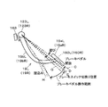
このため、ハンドルポスト6から突出した前後進レバー10の突出部10a(図7)は、屈折部10bを有して上方へ向かい把持部10cを有している。このため、把持部10c部分は、ステアリングハンドル7を把持したままの状態で、指先で操作できる。前後進レバー10を少し引き上げて前方へ移動させると前進位置となり、前後進レバー10を少し引き上げて後方へ移動させると後進位置となる。   For this reason, the projecting portion 10a (FIG. 7) of the forward / backward advancing lever 10 projecting from the handle post 6 has the bending portion 10b, and has the gripping portion 10c facing upward. Therefore, the grip portion 10 c can be operated with a fingertip while holding the steering handle 7. When the forward and reverse lever 10 is slightly pulled up and moved forward, it is in the forward position, and when it is slightly pulled up and moved backward, it is in the reverse position.

また、ハンドルポスト6を挟んで前後進レバー10の反対側にはエンジン回転数を調節するアクセルレバー11が設けられ、またステップフロア13の右コーナー部には、同様にエンジン回転数を調節するアクセルペダル18と、左右の後輪3,3のそれぞれに設けるブレーキ135L、135R(図2)を作動させる左ブレーキペダル19Lと右ブレーキペダル19Rが設けられている。   In addition, an accelerator lever 11 for adjusting the engine speed is provided on the opposite side of the handlebar post 6 and an accelerator lever 11 for adjusting the engine speed. A left brake pedal 19L and a right brake pedal 19R are provided for operating the pedals 18 and the brakes 135L and 135R (FIG. 2) provided on the left and right rear wheels 3 and 3, respectively.

左ブレーキペダル19Lと右ブレーキペダル19Rを一体的に連結するブレーキ連結杆94を設け、このブレーキ連結杆94で連結した状態で左ブレーキペダル19Lか右ブレーキペダル19Rのどちらかを踏み込むとトラクタ1の走行が停止するが、その停止制御については後述する。   A brake connection rod 94 connecting the left brake pedal 19L and the right brake pedal 19R integrally is provided, and when the left brake pedal 19L or the right brake pedal 19R is depressed while being connected by the brake connection rod 94, the tractor 1 The travel is stopped, but the stop control will be described later.

ブレーキ連結杆94を非連結の状態にすると、左ブレーキペダル19Lと右ブレーキペダル19Rは独立して使用可能となり、圃場内での旋回時に旋回内側のブレーキペダル19L又は19Rを踏み込み操作することで、旋回半径を小さくして旋回できる(手動のブレーキターン)。   When the brake connection lever 94 is in the non-connected state, the left brake pedal 19L and the right brake pedal 19R can be used independently, and by stepping on the inward turning brake pedal 19L or 19R when turning in the field, You can turn by reducing the turning radius (manual brake turn).

ハンドルポスト6を挟んで左ブレーキペダル19Lと右ブレーキペダル19Rの反対側には、クラッチペダル1002を設けている。
ハンドルポスト6上部のステアリングハンドル7の前側に図6に示すフロントメータパネル16が設けられており、このフロントメータパネル16の中央部に液晶表示部1001を設けている。液晶表示部1001の左側にタコメータ136を設け、液晶表示部1001の右側に表示灯パネル145を設けている。
A clutch pedal 1002 is provided on the opposite side of the left brake pedal 19L and the right brake pedal 19R with the steering wheel post 6 interposed therebetween.
A front meter panel 16 shown in FIG. 6 is provided on the front side of the steering wheel 7 above the steering wheel post 6, and a liquid crystal display portion 1001 is provided at the center of the front meter panel 16. A tachometer 136 is provided on the left side of the liquid crystal display unit 1001, and an indicator light panel 145 is provided on the right side of the liquid crystal display unit 1001.

エンジン回転数がタコメータ136に表示され、表示灯パネル145にノークラ表示灯146と低圧警告灯147を設けている。また、図7のように、ハンドルポスト6の左下部にノークラッチ設定スイッチ126を設けている。このノークラッチ設定スイッチ126の右側には表示切換スイッチ1000を設けており、この表示切換スイッチ1000を押し操作する毎に、前記液晶表示部1001に表示される内容が切り換わる構成としている。   The engine speed is displayed on the tachometer 136, and the indicator light panel 145 is provided with a nokra indicator light 146 and a low pressure warning light 147. Further, as shown in FIG. 7, the no clutch setting switch 126 is provided at the lower left portion of the steering wheel post 6. A display changeover switch 1000 is provided on the right side of the no clutch setting switch 126, and the content displayed on the liquid crystal display unit 1001 is switched each time the display changeover switch 1000 is pressed.

また、一速から八速まで変速する主変速レバー14はシート9の左前側部にあり、超低速、低速、中速、高速の四段及び中立のいずれかの位置を選択できる副変速レバー(変速操作手段)15はその後方にあり、さらにその右側に四段に変速するPTO変速レバー12を設けている。トラクタ1の機体後部には、ロータリ作業機17を装着して、ミッションケース8から後方へ突出するPTO出力軸111で駆動するようにしている。   The main shift lever 14 for shifting from first gear to eighth gear is located on the left front side of the seat 9 and is an auxiliary shift lever that can select any of four positions of super low speed, low speed, medium speed and high speed and neutral. The shift operating means 15 is located at the rear of the PTO shift lever 12 on the right side of the shift operation means 15 to shift to four steps. A rotary working machine 17 is attached to the rear portion of the tractor 1 and is driven by a PTO output shaft 111 projecting rearward from the transmission case 8.

図2は、ミッションケース8内の変速装置の動力伝動機構を示す伝動線図で、エンジン5から前輪2と後輪3及びロータリ作業機17へのPTO出力軸111への変速伝動機構を説明する。   FIG. 2 is a transmission line diagram showing the power transmission mechanism of the transmission in the transmission case 8 and explains the transmission transmission mechanism from the engine 5 to the PTO output shaft 111 to the front wheels 2 and rear wheels 3 and the rotary work machine 17. .

エンジン5のエンジン出力軸20の回転がミッションケース8内のミッション入力軸21に伝動される。このミッション入力軸21に固着の第一入力ギヤ22と第二入力ギヤ23がそれぞれ第一高・低クラッチ24の第一低速ギヤ26と第二高・低クラッチ25の第二低速ギヤ27及び第一高・低クラッチ24の第一高速ギヤ30と第二高・低クラッチ25の第二高速ギヤ31に噛み合って回転を伝動している。   The rotation of the engine output shaft 20 of the engine 5 is transmitted to the transmission input shaft 21 in the transmission case 8. The first input gear 22 and the second input gear 23 fixed to the transmission input shaft 21 are the first low speed gear 26 of the first high and low clutch 24 and the second low speed gear 27 and the second high and low clutch 25 respectively. The rotation is transmitted by meshing with the first high speed gear 30 of the one high / low clutch 24 and the second high speed gear 31 of the second high / low clutch 25.

そして、第一高・低クラッチ24を第一低速ギヤ26側に繋ぐと第一低速ギヤ26から第一クラッチ軸28に伝動され、第一高速ギヤ30側に繋ぐと第一高速ギヤ30から第一クラッチ軸28に伝動され、第二高・低クラッチ25を第二低速ギヤ27側に繋ぐと第二低速ギヤ27から第二クラッチ軸29に伝動され、第二高速ギヤ31側に繋ぐと第二高速ギヤ31から第二クラッチ軸29に伝動される。   When the first high / low clutch 24 is connected to the first low speed gear 26, the first low speed gear 26 is transmitted to the first clutch shaft 28, and when connected to the first high speed gear 30, the first high speed gear 30 is connected to the first high speed gear 30. When it is transmitted to one clutch shaft 28 and the second high / low clutch 25 is connected to the second low speed gear 27 side, it is transmitted from the second low speed gear 27 to the second clutch shaft 29 and connected to the second high speed gear 31 side. The second high speed gear 31 is transmitted to the second clutch shaft 29.

第一高・低クラッチ24と第二高・低クラッチ25は同一の油圧多板クラッチで、それぞれミッション入力軸21の回転を同一減速比で高・低の二段に減速して第一クラッチ軸28と第二クラッチ軸29に伝動することになる。   The first high and low clutches 24 and the second high and low clutches 25 are the same hydraulic multi-disc clutches, and respectively reduce the rotation of the transmission input shaft 21 into two stages of high and low with the same reduction ratio to obtain the first clutch shaft 28 and the second clutch shaft 29 will be transmitted.

また、図4に示すように、第一高・低クラッチ24と第二高・低クラッチ25は、潤滑オイルに浸かり、その第一クラッチ軸28と第二クラッチ軸29が潤滑オイルの液面OLより若干上に位置している。   Further, as shown in FIG. 4, the first high and low clutch 24 and the second high and low clutch 25 are immersed in the lubricating oil, and the first clutch shaft 28 and the second clutch shaft 29 are the liquid level OL of the lubricating oil. Located slightly above.

更に、図3に示すように、第一クラッチ軸28と第二クラッチ軸29をミッションケース8に支持する前仕切壁181に形成した肉盛部181aにケースの左右開口部側からドリルで加工した給油孔8bを設けて、この給油孔8bから第一高・低クラッチ24と第二高・低クラッチ25の軸に給油している。   Furthermore, as shown in FIG. 3, a buildup portion 181 a formed on the front partition wall 181 supporting the first clutch shaft 28 and the second clutch shaft 29 to the transmission case 8 was drilled from the left and right opening side of the case An oil supply hole 8 b is provided, and the shafts of the first high / low clutch 24 and the second high / low clutch 25 are supplied with oil from the oil supply hole 8 b.

また、図5に示すように、第一高・低クラッチ24と第二高・低クラッチ25は、ミッションケース8の下り傾斜部8cの下部で、左右に配置している。
図2に示す第一クラッチ軸28に固着の第一ギヤ113が低速伝動軸34に固着の第二ギヤ35と噛み合って減速して伝動され、第二クラッチ軸29に固着の第三ギヤ149が高速伝動軸32に固着の第四ギヤ33と噛み合って増速して伝動される。
Further, as shown in FIG. 5, the first high / low clutch 24 and the second high / low clutch 25 are disposed on the left and right under the downward inclined portion 8 c of the transmission case 8.
The first gear 113 fixed to the first clutch shaft 28 shown in FIG. 2 is engaged with the second gear 35 fixed to the low speed transmission shaft 34, decelerated and transmitted, and the third gear 149 fixed to the second clutch shaft 29 The fourth gear 33 fixed to the high speed transmission shaft 32 engages with the fourth gear 33 to accelerate and transmit power.

ここまでの変速伝動で、低速伝動軸34が低速で二段に、高速伝動軸32が高速で二段にそれぞれ変速されることで、計四段に変速されることになる。
そして、低速伝動軸34と高速伝動軸32の回転がそれぞれ第一シンクロチェンジ42と第二シンクロチェンジ36に伝動され、第一シンクロチェンジ42の第一シンクロ小ギヤ43と第二シンクロチェンジ36の第二シンクロ小ギヤ37が第一伝動軸39の第五ギヤ40と噛み合い、第一シンクロチェンジ42の第一シンクロ大ギヤ44と第二シンクロチェンジ36の第二シンクロ大ギヤ38が第一伝動軸39の第六ギヤ41と噛み合って伝動する。
By shifting the low-speed transmission shaft 34 to two speeds at low speeds and shifting the high-speed transmission shaft 32 to two speeds at high speeds, the total transmission speed is four.
Then, the rotations of the low speed transmission shaft 34 and the high speed transmission shaft 32 are transmitted to the first sync change 42 and the second sync change 36 respectively, and the first sync small gear 43 of the first sync change 42 and the second sync change 36 The two small synchro gears 37 mesh with the fifth gear 40 of the first transmission shaft 39, and the first large synchro gear 44 of the first synchro change 42 and the second large synchro gear 38 of the second synchro change 36 are the first transmission shaft 39. The gear is engaged with the sixth gear 41 of FIG.

第一シンクロチェンジ42の第一シンクロ小ギヤ43と第一シンクロギヤ大44及び第二シンクロチェンジ36の第二シンクロ小ギヤ37と第二シンクロ大ギヤ38は、全く同一のギヤで、低速伝動軸34が低速回転し高速伝動軸32が高速回転しているので、第一シンクロチェンジ42を切換えると低速でさらに二段に変速され、第二シンクロチェンジ36を切換えると高速でさらに二段に変速される。即ち、ミッション入力軸21の回転が第一伝動軸39で低速四段と高速四段に変速されることになる。   The first synchro small gear 43 of the first synchro change 42 and the second synchro small gear 37 and the second synchro large gear 38 of the first synchro gear large 44 and the second synchro change 36 are completely the same gear, and the low speed transmission shaft Since the high speed transmission shaft 32 rotates at a low speed while the high speed transmission shaft 32 rotates at a low speed, the speed is further changed to two speeds at low speed when the first synchro change 42 is switched, and the speed is further changed to two stages at high speed when the second synchro change 36 is switched. Ru. That is, the rotation of the transmission input shaft 21 is shifted by the first transmission shaft 39 into four low speeds and four high speeds.

第一シンクロチェンジ42と第二シンクロチェンジ36はシフタステーとシフタをサブ組付けしてミッションケース8内に収められ、その変速操作部のケース開口部がケースの左右側面に設けられ、ミッションケース8の潤滑オイルの液面OLよりも上側に設けられる。   The first synchro change 42 and the second synchro change 36 are sub-assembled with the shifter stay and the shifter and housed in the transmission case 8, and case openings of the transmission operation portion are provided on the left and right sides of the case. It is provided above the liquid level OL of the lubricating oil.

ここまでの主変速部150で、主変速レバー14の基部に設けた主変速レバー位置センサ171(図8)により、操縦者が操作する主変速レバー14の変速位置を読み取って、コントローラ(制御装置)120で自動的に高・低油圧多板クラッチ24,25と第一・第二シンクロチェンジ36,42を制御して低速四段と高速四段まで変速(八段変速)される。また、ミッションケース8内で、第一高・低クラッチ24と第二高・低クラッチ25が左右に配置され、その下側に第一シンクロチェンジ42を装着する低速伝動軸34と第二シンクロチェンジ36を装着する高速伝動軸32が左右に配置されることで、ミッションケース8の左右幅が狭く高さの低いコンパクトな構成となる。   The controller (control device) reads the shift position of the main shift lever 14 operated by the operator by the main shift lever position sensor 171 (FIG. 8) provided at the base of the main shift lever 14 in the main shift unit 150 so far. And 120) automatically control the high / low hydraulic pressure multi-disc clutches 24 and 25 and the first and second synchro changes 36 and 42 to shift to four low and four high speeds (eight-speed). Also, in the transmission case 8, the first high / low clutch 24 and the second high / low clutch 25 are disposed on the left and right sides, and the low speed transmission shaft 34 and the second synchro change By arranging the high-speed transmission shaft 32 on which the 36 is mounted to the left and right, the transmission case 8 has a compact configuration with a narrow horizontal width and a low height.

さらに、第一伝動軸39は第二伝動軸45に軸連結によって連結されている。この第二伝動軸45には、第七ギヤ46と第八ギヤ47が固着され、第七ギヤ46が正転クラッチギヤ49と噛み合い、第八ギヤ47が逆転ギヤ51と噛み合い、逆転ギヤ51が前後進クラッチ48の逆転クラッチギヤ50と噛み合っている。   Furthermore, the first transmission shaft 39 is connected to the second transmission shaft 45 by axial connection. The seventh gear 46 and the eighth gear 47 are fixed to the second transmission shaft 45, and the seventh gear 46 meshes with the forward clutch gear 49, the eighth gear 47 meshes with the reverse gear 51, and the reverse gear 51 It meshes with the reverse rotation clutch gear 50 of the forward and reverse clutch 48.

従って、前後進クラッチ48の前進クラッチ48aを接続して正転クラッチギヤ49に繋ぐと、正転状態(前進)で前後進クラッチ48に連結の副変速軸53に伝動され、前後進クラッチ48の後進クラッチ48bを接続して逆転クラッチギヤ50に繋ぐと、逆転状態(後進)で副変速軸53に伝動される。正転と逆転では減速比が異なり、逆転の方が低速になる。前後進レバー10を前進位置にすると、前進クラッチ48aが接続され、前後進レバー10を後進位置にすると、後進クラッチ48bが接続される。   Therefore, when the forward clutch 48 a of the forward and reverse clutch 48 is connected and connected to the forward rotation clutch gear 49, the auxiliary transmission shaft 53 connected to the forward and reverse clutch 48 is transmitted in the forward rotation state (forward). When the reverse clutch 48b is connected and connected to the reverse clutch gear 50, the power is transmitted to the auxiliary transmission shaft 53 in the reverse state (reverse). The reduction ratio is different between forward and reverse, and reverse is slower. When the forward and reverse lever 10 is in the forward position, the forward clutch 48a is connected, and when the forward and reverse lever 10 is in the reverse position, the reverse clutch 48b is connected.

また、前後進クラッチ48の支持軸をミッションケース8に支持する後仕切壁182に形成した肉盛部182aにケースのケース外側からドリルで加工した給油孔182bを設けて、この給油孔182bから前後進クラッチ48の支持軸に給油している。   Further, the buildup portion 182a formed on the rear partition wall 182 supporting the support shaft of the forward and reverse clutch 48 to the transmission case 8 is provided with the oil supply hole 182b drilled from the outside of the case of the case. The support shaft of the forward clutch 48 is being refueled.

なお、前輪増速クラッチ79やPTOメインクラッチ97への給油孔もミッションケース8の内側に設けた肉盛部に形成している。   Note that the oil supply holes to the front wheel speed increasing clutch 79 and the PTO main clutch 97 are also formed in the build-up portion provided inside the transmission case 8.

次に、副変速部154について説明する。
副変速軸53には第九ギヤ54と第十ギヤ55が固着され、それぞれ第三シンクロチェンジ58の第三シンクロ大ギヤ56と第三シンクロ小ギヤ59に噛み合っている。従って、第三シンクロチェンジ58を第三シンクロ大ギヤ56側に繋ぐと第九ギヤ54から第三シンクロ大ギヤ56に伝動した回転で第五伝動軸60が増速して高速で駆動され、第三シンクロチェンジ58を第三シンクロ小ギヤ59側に繋ぐと第十ギヤ55から第三シンクロ小ギヤ59に伝動した回転で第五伝動軸60が減速して中速で駆動される。
Next, the auxiliary transmission unit 154 will be described.
The ninth gear 54 and the tenth gear 55 are fixed to the auxiliary transmission shaft 53, and are engaged with the third large synchro gear 56 and the third small synchro gear 59 of the third synchro change 58, respectively. Therefore, when the third synchro change 58 is connected to the third large synchro gear 56, the fifth transmission shaft 60 is accelerated at high speed by the rotation transmitted from the ninth gear 54 to the third large synchro gear 56, and When the third synchro change 58 is connected to the third small synchro gear 59, the fifth transmission shaft 60 is decelerated and driven at an intermediate speed by the rotation transmitted from the tenth gear 55 to the third small synchro gear 59.

さらに、第三シンクロチェンジ58の第三シンクロ小ギヤ59側には第十一ギヤ57を固着して、第四シンクロチェンジ71の第四シンクロ小ギヤ69と噛み合っている。そして、第四シンクロ小ギヤ69側には第十五ギヤ70を固着し、この第十五ギヤ70が第二筒軸114の第十七ギヤ75と噛み合って第二筒軸114に固着の第十八ギヤ76から第四シンクロ大ギヤ72に伝動している。第四シンクロチェンジ71を装着した第一筒軸73には、第十六ギヤ74を固着している。   Further, an eleventh gear 57 is fixed to the third sync small gear 59 side of the third sync change 58, and is engaged with the fourth sync small gear 69 of the fourth sync change 71. Then, the fifteenth gear 70 is fixed to the fourth synchro small gear 69 side, and the fifteenth gear 70 meshes with the seventeenth gear 75 of the second cylindrical shaft 114 to be fixed to the second cylindrical shaft 114. It is transmitted from the eighteenth gear 76 to the fourth large synchro gear 72. A sixteenth gear 74 is fixed to the first cylindrical shaft 73 on which the fourth synchro change 71 is mounted.

従って、第三シンクロチェンジ58を中立にすると、第十ギヤ55の回転が第三シンクロ小ギヤ59に伝動され、第三シンクロ小ギヤ59側に固着の第十一ギヤ57から第四シンクロ小ギヤ69に伝動される。   Therefore, when the third synch change 58 is made neutral, the rotation of the tenth gear 55 is transmitted to the third synch small gear 59, and the eleventh gear 57 to the fourth synch small gear fixed on the third synch small gear 59 side It is transmitted to 69.

この状態で、第四シンクロチェンジ71を第四シンクロ小ギヤ69側に繋ぐと、第四シンクロ小ギヤ69の回転が第十六ギヤ74の回転となって低速となり、第四シンクロチェンジ71を第四シンクロ大ギヤ72側に繋ぐと第四シンクロ小ギヤ69の回転が第十五ギヤ70から第十七ギヤ75と第十八ギヤ76と第四シンクロ大ギヤ72に伝動されて第十六ギヤ74が極低速となる。   In this state, when the fourth sync change 71 is connected to the fourth sync small gear 69, the rotation of the fourth sync small gear 69 becomes the low speed as the sixteenth gear 74 rotates, and the fourth sync change 71 is When it is connected to the fourth synchro large gear 72 side, the rotation of the fourth small synchro gear 69 is transmitted from the fifteenth gear 70 to the seventeenth gear 75, the eighteenth gear 76 and the fourth synchro large gear 72, and the sixteenth gear 74 is extremely slow.

なお、第三シンクロチェンジ58を第三シンクロ大ギヤ56側或いは第三シンクロ小ギヤ59側に繋ぐ場合には、第四シンクロチェンジ71を中立にしておく。
従って、主変速部150で変速された副変速軸53の低速四段と高速四段が、副変速部154で四段に変速されることで、低速十六段と高速十六段に変速(合計32段)されることになる。これにより、前記前後進クラッチ48を切り換えることで、前進32段、後進32段の変速段となる。変速段については後述する。
When the third synch change 58 is connected to the third synch large gear 56 side or the third synch small gear 59 side, the fourth synch change 71 is made neutral.
Therefore, the four low-speed stages and the four high-speed stages of the auxiliary transmission shaft 53 shifted by the main transmission unit 150 are shifted to the four stages by the auxiliary transmission unit 154, thereby shifting to 16 low-speed stages and 16 high-speed stages ( It will be 32 stages in total. As a result, by switching the forward and reverse clutch 48, 32 forward gear stages and 32 reverse gear stages are obtained. The transmission gear will be described later.

さらに、第十六ギヤ74は前記第五伝動軸60に固着の第十二ギヤ61と噛み合って第五伝動軸60を駆動する。この第五伝動軸60の軸端に固着の第一ベベルギヤ62がリアベベルケース64の第二ベベルギヤ63と噛み合っていて、リアベベルケース64のベベル出力軸65から第十三ギヤ66と第十四ギヤ67を介して後輪出力軸68を回転して後輪3を駆動する。左右の後輪出力軸68には右ブレーキペダル19Rと左ブレーキペダル19Lでそれぞれ作動するブレーキ135(左ブレーキ135L、右ブレーキ135R)を設けている。   Further, the sixteenth gear 74 meshes with the twelfth gear 61 fixed to the fifth transmission shaft 60 to drive the fifth transmission shaft 60. The first bevel gear 62 fixed to the shaft end of the fifth transmission shaft 60 meshes with the second bevel gear 63 of the rear bevel case 64, and the bevel output shaft 65 of the rear bevel case 64 to the thirteenth gear 66 and the fourteenth The rear wheel output shaft 68 is rotated via the gear 67 to drive the rear wheel 3. The left and right rear wheel output shafts 68 are provided with brakes 135 (left brake 135L and right brake 135R) that are operated by the right brake pedal 19R and the left brake pedal 19L, respectively.

また、第五伝動軸60には第二十一ギヤ117が固着され、副変速軸53に軸支された第二筒軸119に固着の第二十二ギヤ118と第二十二ギヤ148を介して第一前輪駆動軸78の第十九ギヤ77に伝動して、前記第十六ギヤ74の低速十六段と高速十六段の回転が第一前輪駆動軸78に伝動されている。   Further, the twenty-first gear 117 is fixed to the fifth transmission shaft 60, and the twenty-second gear 118 and the twenty-second gear 148 fixed to the second cylindrical shaft 119 axially supported by the auxiliary transmission shaft 53. Transmission to the nineteenth gear 77 of the first front wheel drive shaft 78 is performed, and the rotation of the sixteenth gear 74 at low speed sixteen steps and high speed sixteen steps is transmitted to the first front wheel drive shaft 78.

この第一前輪駆動軸78から前輪増速クラッチ79を介して第二前輪駆動軸84に伝動し、第三前輪駆動軸85と第四前輪駆動軸86と前輪駆動ベベル軸87に引き継いで伝動し、前輪駆動ベベル軸87の軸端に固着の第一前ベベルギヤ88が前ベベルケース89の第二前ベベルギヤ115と噛み合っていて、前ベベルケース89の前ベベル出力軸90から第一前ベベルギヤ組91と前縦軸116と第二前ベベルギヤ組92を介して前輪出力軸93を回転して前輪2を駆動する。   The power is transmitted from the first front wheel drive shaft 78 to the second front wheel drive shaft 84 through the front wheel speed increasing clutch 79, and then transmitted to the third front wheel drive shaft 85, the fourth front wheel drive shaft 86, and the front wheel drive bevel shaft 87. The first front bevel gear 88 fixed to the shaft end of the front wheel drive bevel shaft 87 meshes with the second front bevel gear 115 of the front bevel case 89 and the front bevel gear set 91 from the front bevel output shaft 90 of the front bevel case 89 The front wheel output shaft 93 is rotated through the front longitudinal axis 116 and the second front bevel gear set 92 to drive the front wheel 2.

前輪増速クラッチ79の増速クラッチ79bを接続すると、第一増速クラッチギヤ82、第一増速ギヤ83、第二増速ギヤ81、第二増速クラッチギヤ80、第二前輪駆動軸84と伝動されていき、この流れは後輪3に対して前輪2を増速する伝動となる。前輪増速クラッチ79の4WDクラッチ79aを接続すると、第一増速クラッチギヤ82の回転は、同軸芯の第二前輪駆動軸84に伝動される。   When the speed increasing clutch 79 b of the front wheel speed increasing clutch 79 is connected, the first speed increasing clutch gear 82, the first speed increasing gear 83, the second speed increasing gear 81, the second speed increasing clutch gear 80, and the second front wheel drive shaft 84 The flow is a transmission that accelerates the front wheel 2 relative to the rear wheel 3. When the 4WD clutch 79 a of the front wheel acceleration clutch 79 is connected, the rotation of the first acceleration clutch gear 82 is transmitted to the second front wheel drive shaft 84 having the coaxial core.

この流れは前輪2を後輪3と同じ速度にする4WD駆動となる。前記増速クラッチ79bと4WDクラッチ79aのいずれも接続しない場合は、後輪駆動のみの2WD走行となる。   This flow is 4WD drive that makes the front wheel 2 the same speed as the rear wheel 3. When neither the speed increasing clutch 79 b nor the 4WD clutch 79 a is connected, 2WD traveling is performed only with rear wheel drive.

副変速レバー位置センサ(変速操作位置検出手段)134(副変速レバー15の基部に設けられる)が副変速レバー15の変速位置を読み取って、コントローラ120(図8)で自動的に第三シンクロチェンジ58と第四シンクロチェンジ71を制御して変速される。また、第四シンクロチェンジ71を装着した第一筒軸73は、第三シンクロチェンジ58を装着した第五伝動軸60の下側に配置されており、ミッションケース8の長さを短く出来る。第三シンクロチェンジ58と第四シンクロチェンジ71については、副変速レバー15とリンク機構等で接続してメカチェンジ機構に構成してもよい。メカチェンジ機構はシンクロ無しで、一旦停車しないと変速できない構成である。   The auxiliary shift lever position sensor (shift operation position detection means) 134 (provided at the base of the auxiliary shift lever 15) reads the shift position of the auxiliary shift lever 15, and the controller 120 (FIG. 8) automatically performs the third synchro change. The gear shift is performed by controlling the 58 and the fourth synchro change 71. Further, the first cylindrical shaft 73 mounted with the fourth synchro change 71 is disposed below the fifth transmission shaft 60 mounted with the third synchro change 58, and the length of the transmission case 8 can be shortened. The third sync change 58 and the fourth sync change 71 may be configured as a mechanical change mechanism by being connected to the auxiliary transmission lever 15 by a link mechanism or the like. The mechanical change mechanism does not have a synchronization, and can not change gear without stopping once.

次に、PTO出力軸111の伝動経路を説明する。
前記第二入力ギヤ23にPTOメインクラッチ97のメインクラッチギヤ96を噛み合わせて、PTOメインクラッチ97で動力の断続を行うようにしている。このPTOメインクラッチ97は、図5に示すように、第一高・低クラッチ24と第二高・低クラッチ25の下側に位置して、ミッションケース8の内部に溜まる潤滑オイルで冷却・潤滑される。
Next, the transmission path of the PTO output shaft 111 will be described.
The main clutch gear 96 of the PTO main clutch 97 is engaged with the second input gear 23, and power is interrupted by the PTO main clutch 97. The PTO main clutch 97 is located below the first high / low clutch 24 and the second high / low clutch 25 as shown in FIG. 5 and is cooled / lubricated with lubricating oil accumulated inside the transmission case 8. Be done.

PTOメインクラッチ97を装着した第一PTO軸95には、次のように、PTO変速部157が設けられている。
即ち第一PTO軸95に、第一PTOギヤ98と第二PTOギヤ99と第五シンクロチェンジ151の第五シンクロ小ギヤ100と第五シンクロ大ギヤ101を装着し、第二PTO軸104に第二十ギヤ102と第二十三ギヤ152と第二十一ギヤ103と第二十四ギヤ153を固着し、カウンタ軸106にPTO逆転ギヤ105を軸支している。
On the first PTO shaft 95 with the PTO main clutch 97 mounted, a PTO transmission unit 157 is provided as follows.
That is, the first PTO shaft 98 is fitted with the first PTO gear 98, the second PTO gear 99, and the fifth small gear 100 and the fifth large gear 101 of the fifth synchro change 151, and the second PTO shaft 104 is The twenty-second gear 102, the twenty-third gear 152, the twenty-first gear 103, and the twenty-fourth gear 153 are fixed, and a PTO reverse gear 105 is axially supported on the counter shaft 106.

第一PTOギヤ98をスライドして第二十ギヤ102に噛み合わせると第三PTO軸107が二速になり、第一PTOギヤ98をスライドして第二PTOギヤ99に係合すると第一PTO軸95の回転が第二PTOギヤ99と第二十三ギヤ152を介して第三PTO軸107に伝わって四速となり、第五シンクロチェンジ151を第五シンクロ小ギヤ100に繋ぐと第五シンクロ小ギヤ100から第二十一ギヤ103に伝動して一速となり、第五シンクロチェンジ151を第五シンクロ大ギヤ101に繋ぐと第五シンクロ大ギヤ101から第二十四ギヤ153に伝動して三速となり、PTO逆転ギヤ105を第一PTOギヤ98と第二十ギヤ102に噛み合わせると第一PTO軸95の回転が第一PTOギヤ98からPTO逆転ギヤ105を経て第二十ギヤ102に伝動されて第三PTO軸107に伝わって逆回転となる。   When the first PTO gear 98 is slid and engaged with the 20th gear 102, the third PTO shaft 107 becomes the second speed, and when the first PTO gear 98 is slid and engaged with the second PTO gear 99, the first PTO When the rotation of the shaft 95 is transmitted to the third PTO shaft 107 via the second PTO gear 99 and the twenty-third gear 152 and becomes the fourth speed, and the fifth synchro change 151 is connected to the fifth small synchro gear 100, the fifth synchro The first gear is transmitted from the small gear 100 to the 21st gear 103, and when the fifth synchro change 151 is connected to the fifth synchro large gear 101, the fifth synchro large gear 101 is transmitted to the 24th gear 153. When the PTO reverse gear 105 is engaged with the first PTO gear 98 and the twentieth gear 102 in the third speed, the rotation of the first PTO shaft 95 starts the PTO reverse gear 105 from the first PTO gear 98. Article is transmitted to the gear 102 becomes reverse rotation transmitted to the third PTO shaft 107 Te.

また、図5に示すように、第一PTOギヤ98と第二PTOギヤ99と第五シンクロチェンジ151は、前記第一高・低クラッチ24及び第二高・低クラッチ25と第一シンクロチェンジ42及び第二シンクロチェンジ36の間で、下側に配置している。   Further, as shown in FIG. 5, the first PTO gear 98, the second PTO gear 99, and the fifth synchro change 151 have the first high / low clutch 24 and the second high / low clutch 25 and the first synchro change 42. And between the second synchro change 36, the lower side.

第三PTO軸107の回転は、第四PTO軸156を介して第五PTO軸108に伝動し、第一PTO出力ギヤ109から第二PTO出力ギヤ110への伝動で更に減速してPTO出力軸111を駆動する。   The rotation of the third PTO shaft 107 is transmitted to the fifth PTO shaft 108 via the fourth PTO shaft 156, and further decelerated by the transmission from the first PTO output gear 109 to the second PTO output gear 110, and the PTO output shaft Drive 111;

図4に示すように、ミッションケース8の左右中央にミッション入力軸21と第四前輪駆動軸86が位置し、第一高・低クラッチ24と第二高・低クラッチ25、高速伝動軸32と低速伝動軸34及び第四PTO軸156と副変速軸53が左右対称位置に配置している。   As shown in FIG. 4, the transmission input shaft 21 and the fourth front wheel drive shaft 86 are positioned at the left and right center of the transmission case 8, and the first high / low clutch 24, the second high / low clutch 25, and the high speed transmission shaft 32. The low speed transmission shaft 34, the fourth PTO shaft 156, and the auxiliary transmission shaft 53 are disposed at symmetrical positions in the left-right direction.

また、第四PTO軸156と副変速軸53と第四前輪駆動軸86は、ミッションケース8の内部下方位置で正面視略二等辺三角形の配置となっている。
図8には、ミッションケース8内の変速を制御する自動制御の制御ブロック図を示す。コントローラ120への制御データの入力は、エンジン回転センサ112からのエンジン回転数と、クラッチペダルセンサ121からのオン・オフ信号と、車速センサ122からの走行速度と、右ブレーキ操作位置センサ123Rのセンサ信号と、左ブレーキ操作位置センサ123Lのセンサ信号と、前後進レバー位置センサ124の切換信号と、ブレーキ連結検出スイッチ125のオン・オフ信号と、ノークラッチ設定スイッチ126のオン・オフ信号と、副変速レバー位置センサ134からの副変速レバー15の変速位置と、主変速レバー位置センサ171からの主変速レバー14の変速位置などである。車速センサ122は、ミッションケース8に取り付けられており、車速が検出可能な軸の回転数をピックアップする構成としている。
Further, the fourth PTO shaft 156, the auxiliary transmission shaft 53, and the fourth front wheel drive shaft 86 are arranged in a substantially isosceles triangle in a front view at an inner lower position of the transmission case 8.
FIG. 8 shows a control block diagram of automatic control for controlling the shift in the transmission case 8. The control data input to the controller 120 includes the engine speed from the engine speed sensor 112, the on / off signal from the clutch pedal sensor 121, the traveling speed from the vehicle speed sensor 122, and the sensor of the right brake operation position sensor 123R. Signal, sensor signal of left brake operation position sensor 123L, switching signal of forward / backward lever position sensor 124, on / off signal of brake connection detection switch 125, on / off signal of no clutch setting switch 126, auxiliary These are the shift position of the sub shift lever 15 from the shift lever position sensor 134, the shift position of the main shift lever 14 from the main shift lever position sensor 171, and the like. The vehicle speed sensor 122 is attached to the transmission case 8 and configured to pick up the number of rotations of the shaft that can detect the vehicle speed.

コントローラ120からの制御出力は、前後進クラッチ48を切り替える切替弁である前進ソレノイド127又は後進ソレノイド128への作動信号と、前後進クラッチ48の油圧を昇圧するための前後進昇圧ソレノイド170への作動信号、ブレーキ比例ソレノイド129への作動信号と、右ブレーキソレノイド130Rと左ブレーキソレノイド130Lへの作動信号と、第一高・低クラッチ24と第二高・低クラッチ25と第一シンクロチェンジ42〜第四シンクロチェンジ71への作動信号などである。左右のブレーキペダル19L、19Rの操作により、ブレーキ比例ソレノイド129を作動させて右ブレーキソレノイド130R又は左ブレーキソレノイド130L、又は右ブレーキソレノイド130Rと左ブレーキソレノイド130Lの両方を作動させる。   The control output from the controller 120 is an operation signal to the forward solenoid 127 or the reverse solenoid 128 which is a switching valve for switching the forward / reverse clutch 48 and an operation to the forward / backward boost solenoid 170 for boosting the hydraulic pressure of the forward / reverse clutch 48. Signals, operation signals to the brake proportional solenoid 129, operation signals to the right brake solenoid 130R and the left brake solenoid 130L, the first high / low clutch 24, the second high / low clutch 25, the first synchro change 42 to the fourth 4 operation signals to the synchro change 71 and the like. By operating the left and right brake pedals 19L and 19R, the brake proportional solenoid 129 is operated to operate the right brake solenoid 130R or the left brake solenoid 130L, or both the right brake solenoid 130R and the left brake solenoid 130L.

次に、制動制御について説明する。
前記のように、左ブレーキペダル19Lと右ブレーキペダル19Rは、それぞれを踏み込むことで踏み込んだ側のブレーキ135(135L又は135R)を作動させてその作動側へ旋回する。
Next, braking control will be described.
As described above, the left brake pedal 19L and the right brake pedal 19R operate to turn on the brake 135 (135L or 135R) on the depressed side by depressing the left brake pedal 19L and the right brake pedal 19R.

そして、左ブレーキペダル19Lと右ブレーキペダル19Rをブレーキ連結杆94で連結したことをブレーキ連結検出スイッチ(センサ)125が検出し、ノークラッチ設定スイッチ126をオンしたことを検出すると、「ノークラッチブレーキ作動状態」となる。この状態で、表示灯パネル145のノークラ表示灯146(図6)が点灯する。また、ブレーキ連結検出スイッチ125が非連結状態のときは、ノークラ表示灯146が点滅して「ノークラッチブレーキ作動状態」が機能していないことを知らせる。「ノークラッチブレーキ作動状態」とは、クラッチペダル1002を踏まなくても左右のブレーキペダル19L、19Rの操作だけで機体の停止と発進ができるトラクタの操作態様である。   Then, when the brake connection detection switch (sensor) 125 detects that the left brake pedal 19L and the right brake pedal 19R are connected by the brake connection rod 94 and detects that the no clutch setting switch 126 is turned on, “No clutch brake "Operating state". In this state, the no lamp lamp 146 (FIG. 6) of the signal lamp panel 145 is turned on. Further, when the brake connection detection switch 125 is in the non-connected state, the no-cla light 146 blinks to notify that the "no clutch brake operating state" is not functioning. The "no-clutch brake operating state" is an operation mode of a tractor that can stop and start the machine only by operating the left and right brake pedals 19L and 19R without stepping on the clutch pedal 1002.

また、メインキースイッチ167(図1)を停止にしても、ノークラッチ設定スイッチ126がオンの場合はオン状態と記憶しているので、再びメインキースイッチ167を入りにすると「ノークラッチブレーキ作動状態」となり、ノークラ表示灯146が点灯する。このとき、ブレーキ連結検出スイッチ125が非連結状態のときは、ノークラ表示灯146が点滅する。   Also, even if the main key switch 167 (FIG. 1) is stopped, the no clutch setting switch 126 is stored in the on state if it is on. Therefore, when the main key switch 167 is turned on again, And the no lamp lamp 146 lights up. At this time, when the brake connection detection switch 125 is in the non-connected state, the no-cla light 146 blinks.

そして、本実施形態のトラクタでは、トラクタの走行中において、ノークラッチブレーキ作動状態(ノークラ表示灯146の点灯時)で右ブレーキペダル19Rか左ブレーキペダル19Lを踏み込んで、即ち、左右のブレーキペダル19L、19Rが同時に踏み込まれると、ブレーキペダル19L、19Rの踏力をブレーキ操作力センサ160L、160Rで検出し、この踏力が規定以上の場合に、前後進クラッチ48の前進クラッチ48a又は後進クラッチ48bの選択されている側のクラッチが全圧から規定の低圧状態(以下、この時の規定の低圧を半クラッチ圧と言い、規定の低圧状態を半クラッチ状態と言う)となる(クラッチ圧低下機能)。   Then, in the tractor of this embodiment, while the tractor is traveling, the right brake pedal 19R or the left brake pedal 19L is depressed in the no-clutch brake operating state (when the no-cla light 146 is lit), that is, the left and right brake pedals 19L. When the 19R is simultaneously depressed, the depression force of the brake pedals 19L and 19R is detected by the brake operation force sensors 160L and 160R, and when the depression force exceeds the predetermined value, the selection of the forward clutch 48a or the reverse clutch 48b of the forward / reverse clutch 48 is performed. From the total pressure to the specified low pressure state (hereinafter, the low pressure specified at this time is referred to as a half clutch pressure, and the specified low pressure state is referred to as a half clutch state) (clutch pressure reduction function).

「ノークラッチブレーキ作動状態」が機能していない場合は、ブレーキペダル19を踏んで後輪3にブレーキ135を掛け、クラッチペダル1002を踏んでエンジン5からの動力を完全に切断して停車する。クラッチペダル1002を踏まないとエンストしてしまうからである。   When the "no clutch brake operation state" is not functioning, the brake pedal 19 is depressed to apply the brake 135 to the rear wheel 3, the clutch pedal 1002 is depressed, the power from the engine 5 is completely disconnected, and the vehicle stops. This is because the engine is stalled unless the clutch pedal 1002 is depressed.

「ノークラッチブレーキ作動状態」の場合は、ブレーキペダル19L、19Rの操作により後輪3、3にブレーキ135を作動させることで機体は停車する。このとき、同時にクラッチの接続作動圧を全圧から低下させ、規定の低圧にする。低下させないとエンストする。停車時に規定の低圧にすることで、以下の効果を奏する。   In the case of the "no clutch brake operating state", the vehicle is stopped by operating the brakes 19 on the rear wheels 3 and 3 by operating the brake pedals 19L and 19R. At this time, at the same time, the connection operating pressure of the clutch is reduced from the total pressure to a prescribed low pressure. If it doesn't decrease it will stall. By setting the specified low pressure when the vehicle is stopped, the following effects can be obtained.

まず、再発進時に速やかに走行を開始できる。そして、平坦路ではブレーキペダル19を離すのみで(アクセルペダル18は踏まない)超低速で走行を開始する。また、登り坂ではブレーキペダル19を離すと(アクセルペダル18は踏まない)、急傾斜では若干後進するものの、そうでない場合は後進しない。従って、坂道発進が容易となる。   First, traveling can be started promptly upon re-starting. Then, on a flat road, traveling is started at an ultra low speed only by releasing the brake pedal 19 (without stepping on the accelerator pedal 18). Further, when the brake pedal 19 is released on the uphill (the accelerator pedal 18 is not depressed), although the vehicle slightly reverses at the steep slope, it does not reverse otherwise. Therefore, the slope start can be facilitated.

図9には、左ブレーキペダル19Lの側面図を示す。尚、右ブレーキペダル19Rでも同様の図となる。
左右のブレーキペダル19L、19Rの足載せ部19aL、19aRにそれぞれブレーキ操作力センサ160(左ブレーキ操作力センサ160L、右ブレーキ操作力センサ160R)を設け、ブレーキ開放状態からブレーキペダル19L、19Rを踏み込み、ブレーキ操作力センサ160L、160Rにより規定以上の踏力が検出されると、前後進クラッチ48の接続作動圧を規定の圧力に低下させるように、コントローラ120から前後進昇圧ソレノイド170に制御出力がされる。このときのフローチャートを図10に示す。
FIG. 9 shows a side view of the left brake pedal 19L. The same applies to the right brake pedal 19R.
A brake operation force sensor 160 (left brake operation force sensor 160L, right brake operation force sensor 160R) is provided on each of the footrests 19aL and 19aR of the left and right brake pedals 19L and 19R, and the brake pedals 19L and 19R are depressed from the brake released state When the brake operating force sensors 160L and 160R detect a pedaling force greater than a specified value, the controller 120 outputs a control output to the forward and reverse pressure booster solenoid 170 so as to reduce the connection operating pressure of the forward and reverse clutch 48 to the specified pressure. Ru. A flowchart at this time is shown in FIG.

本構成により、足載せ部19aL、19aRに設けたブレーキ操作力センサ160L、160Rによって実際の踏み力を直に測定できるため、ブレーキ操作していること自体、即ち作業者が意図的にブレーキ操作していることを検出でき、作業者の要望通りに半クラッチの作動圧力とする制御が確実にできる。   According to this configuration, since the actual stepping force can be directly measured by the brake operation force sensors 160L and 160R provided on the footrests 19aL and 19aR, the fact that the brake operation is being performed, that is, the operator intentionally operates the brake Can be detected, and the control of the operating pressure of the half clutch can be assured as desired by the operator.

また、ブレーキペダル19L、19Rの基部側にはブレーキペダル19L、19Rの踏み込み操作を検出するブレーキ操作位置センサ123(右ブレーキ操作位置センサ123R、左ブレーキ操作位置センサ123L)を設けている。右ブレーキ操作位置センサ123Rと左ブレーキ操作位置センサ123Lは、ポテンショメータなどの変位センサ又はスイッチセンサなどのオン・オフ式のセンサでアナログ量を検出するもので良い。   Further, on the base side of the brake pedals 19L and 19R, a brake operation position sensor 123 (right brake operation position sensor 123R and left brake operation position sensor 123L) for detecting a stepping operation of the brake pedals 19L and 19R is provided. The right brake operation position sensor 123R and the left brake operation position sensor 123L may detect an analog amount with an on / off sensor such as a displacement sensor such as a potentiometer or a switch sensor.

例えば、右ブレーキ操作位置センサ123Rと左ブレーキ操作位置センサ123Lは、各ブレーキアーム19bL、19bRの基部(回動軸)に設けたポテンショメータによってストローク量を検出するストロークセンサとし、ブレーキペダル19L、19Rを踏み込んで一定以上のストローク量がブレーキ操作位置センサ123R、123Rによって検出されると(ブレーキ135の入り操作を検出する)、そのセンサ信号がコントローラ120に入力されることによって右ブレーキソレノイド130Rと左ブレーキソレノイド130Lとブレーキ比例ソレノイド129に作動信号が出力され、ブレーキ135L、135Rが作動する。   For example, the right brake operation position sensor 123R and the left brake operation position sensor 123L are stroke sensors that detect a stroke amount by a potentiometer provided at the base (rotational axis) of each brake arm 19bL, 19bR, and the brake pedals 19L, 19R are used. When the brake operation position sensor 123R, 123R detects a predetermined stroke amount or more (detects an on-stroke operation of the brake 135), the sensor signal is input to the controller 120, whereby the right brake solenoid 130R and the left brake are detected. An actuation signal is output to the solenoid 130L and the brake proportional solenoid 129, and the brakes 135L and 135R are actuated.

尚、ブレーキペダル19L、19Rのブレーキ135L、135Rの入切操作を検出するブレーキスイッチ(センサ)163をブレーキ操作位置センサ123R、123Lとは別にブレーキペダル19L、19Rの回動範囲の遊び付近に設け、ブレーキペダル19L、19Rが回動して接触するとブレーキスイッチ163がオンして、ブレーキランプ165が点灯し、ブレーキ135L、135Rが作動する構成としても良い。   A brake switch (sensor) 163 for detecting the on / off operation of the brakes 135L and 135R of the brake pedals 19L and 19R is provided in the vicinity of the play of the rotation range of the brake pedals 19L and 19R separately from the brake operation position sensors 123R and 123L. When the brake pedals 19L and 19R rotate and contact, the brake switch 163 may be turned on, the brake lamp 165 may be lighted, and the brakes 135L and 135R may be actuated.

例えば、前記ノークラッチブレーキ作動状態でのブレーキペダル19L、19Rの踏み込みによる半クラッチ状態の条件として、ブレーキ操作力センサ160L、160Rによって検出される踏力ではなく、ブレーキ操作位置センサ123R、123Lによって検出されるブレーキペダル19L、19Rのストローク量のみを条件とすることも考えられる。   For example, as a condition of the half clutch state by stepping on the brake pedals 19L and 19R in the no-clutch brake operating state, not the pedaling force detected by the brake operating force sensors 160L and 160R but the brake operating position sensors 123R and 123L It may be considered that only the stroke amount of the brake pedals 19L and 19R is set as the condition.

しかし、この場合、ブレーキペダル19L、19Rは経年劣化によって遊びが変化するため、遊びが大きくなるとブレーキ自体が作用するところまで踏み込まれたかどうかが不明となる。また、遊びが小さくなると作業者が意図的にブレーキ操作をしていない場合でも、単にブレーキペダルに足を載せているだけで半クラッチ状態となったりクラッチが入り切りされたりする事態が生じてしまい、クラッチの寿命が短くなってしまう。この場合に遊びを調整することで検出精度を高められるが、使用後の調整が必要となってしまう。   However, in this case, since the play of the brake pedals 19L and 19R changes due to aged deterioration, it becomes unclear whether the brake itself has been depressed if the play becomes large. In addition, if the play is small, even if the operator does not intentionally operate the brake, a situation occurs in which the clutch is partially engaged or the clutch is engaged or disengaged simply by putting the foot on the brake pedal. The life of the clutch will be shortened. In this case, although the detection accuracy can be enhanced by adjusting the play, adjustment after use becomes necessary.

更に、作業者の操作フィーリングとブレーキ操作位置センサ123R、123Lによって検出されるストローク量とが合致しなくなって、作業者がブレーキペダル19L、19Rを意図的に踏み込んでいても、機体の停止動作と作業者の操作フィーリングとが合わなくなってくることもある。   Furthermore, the operation feeling of the operator and the stroke amount detected by the brake operation position sensors 123R, 123L do not match, and even if the operator intentionally depresses the brake pedals 19L, 19R, the stop operation of the machine body And the operator's operation feeling may not match.

そこで、ブレーキ操作位置センサ123R、123Lによるブレーキペダル19L、19Rの踏み込み操作を検出するよりも、ブレーキ操作力センサ160L、160Rによって検出されるブレーキペダル19L、19Rの踏力を、半クラッチ状態とする条件及びブレーキを強く作動させる条件とすることで、作業者の操作フィーリングを損なうことなく機体を減速して停車させ、停車時に半クラッチ状態にすることができる。ブレーキペダル19L、19Rに設けられるブレーキ操作力センサ160L、160Rは、経年変化による遊び量の変化を生じないので、作業者の操作フィーリングを損なうことがない。   Therefore, rather than detecting the depression operation of the brake pedals 19L and 19R by the brake operation position sensors 123R and 123L, the condition that makes the depression force of the brake pedals 19L and 19R detected by the brake operation force sensors 160L and 160R a half clutch state And by setting the condition for strongly operating the brake, it is possible to decelerate and stop the machine without compromising the operation feeling of the operator, and to set the half clutch state when stopping. The brake operation force sensors 160L and 160R provided on the brake pedals 19L and 19R do not cause a change in the amount of play due to the secular change, and therefore do not impair the operation feeling of the operator.

ブレーキペダル19L、19Rが踏まれることで、ブレーキ135を強く作動させると共にクラッチ圧を低下させる。このクラッチ圧は目標とするクラッチ圧であり、停車時のクラッチ圧である。これにより停車時に半クラッチ圧となる。   By depressing the brake pedals 19L and 19R, the brake 135 is strongly operated and the clutch pressure is reduced. The clutch pressure is a target clutch pressure and is a clutch pressure at the time of stopping. As a result, the half clutch pressure is obtained when the vehicle is stopped.

尚、ブレーキ操作力センサ160L、160Rによって規定以上の踏力が検出された場合に加えて、ブレーキ操作位置センサ123R、123Lによってブレーキ135の入り操作が検出されたり、ブレーキスイッチ163がオンすることを、半クラッチ状態の条件としても良い。これにより、ブレーキペダル19L、19Rが間違いなく踏まれたときにクラッチ圧低下機能を作動させるので、ブレーキ作動と半クラッチ状態とを同期させることができる。   Note that, in addition to the case where the brake operating force sensors 160L and 160R detect a pedaling force greater than a predetermined value, the brake operating position sensors 123R and 123L may detect that the brake 135 is engaged or the brake switch 163 may be turned on. It may be a condition of a half clutch state. As a result, the clutch pressure reducing function is activated when the brake pedals 19L and 19R are stepped on with certainty, so it is possible to synchronize the brake operation and the half clutch state.

ブレーキペダル19L、19Rを踏み込んで一定以上のストローク量が検出されるとブレーキ135L、135Rが作動する。そして、この場合に、ブレーキ操作力センサ160L、160Rにより規定以上の踏力による踏み込みが検出されると、前進クラッチ48a又は後進クラッチ48bの選択されている側のクラッチ圧が規定の低圧(半クラッチ状態)となる機能(クラッチ圧低下有効機能)をコントローラ120に設ける構成とする。このときのフローチャートを図11に示す。   When the brake pedals 19L and 19R are depressed and a predetermined stroke amount or more is detected, the brakes 135L and 135R are actuated. Then, in this case, when the brake operating force sensors 160L and 160R detect the depression due to the predetermined pedaling force or more, the clutch pressure on the selected side of the forward clutch 48a or the reverse clutch 48b is a prescribed low pressure (half clutch state Function (clutch pressure reduction effective function) is provided in the controller 120. A flowchart at this time is shown in FIG.

ブレーキペダル19L、19Rの足載せ部19aL、19aRの下部に農具などの道具や部材があると、作業者がブレーキペダル19L、19Rを踏んでも道具が障害となってブレーキペダル19L、19R自体はほとんど動かないのに規定以上の踏力が出てしまうことがある。   If there are tools or members such as agricultural tools under the footrests 19aL, 19aR of the brake pedals 19L, 19R, even if the operator steps on the brake pedals 19L, 19R, the tools become an obstacle and the brake pedals 19L, 19R themselves are almost all Even if it does not move, the treading power beyond the regulation may come out.

本構成により、ブレーキ操作力センサ160L、160Rによって検出されるブレーキペダル19L、19Rの踏力のみならず、ブレーキ操作位置センサ123R、123Lによって検出されるブレーキペダル19L、19Rの入り操作又はブレーキスイッチ163のオンも半クラッチ状態の条件とすることで、ブレーキペダル19L、19Rの踏み込み操作の検出がより確実になる。   With this configuration, not only the depression force of the brake pedals 19L and 19R detected by the brake operation force sensors 160L and 160R but also the on / off operation of the brake pedals 19L and 19R detected by the brake operation position sensors 123R and 123L By setting the ON state also to the condition of the half clutch state, the detection of the depression operation of the brake pedals 19L and 19R becomes more reliable.

そして、ブレーキペダル19L、19Rを踏むと、クラッチ圧を、規定の低圧である目標圧に向かって低下を開始させ、後輪3,3にブレーキ135を強く作動させて減速して機体が停車する。機体が停車時においては、目標圧に保持されて半クラッチ状態が続く。   When the brake pedals 19L and 19R are depressed, the clutch pressure starts decreasing toward the target pressure which is a prescribed low pressure, and the rear wheel 3, 3 is strongly operated by the brake 135 to decelerate and the vehicle stops. . When the vehicle is at rest, the target pressure is maintained and the half clutch state continues.

この低圧停止状態は長く続けると(約2分)油温が高くなるので、前記低圧警告灯147の点灯状態を点滅状態にして操縦者に知らせると良い。油温は油圧回路内に設けた油温センサ172によって検出される。   Since the oil temperature rises as the low pressure stop state continues for a long time (about 2 minutes), it is preferable that the lighting state of the low pressure warning light 147 be blinked to notify the operator. The oil temperature is detected by an oil temperature sensor 172 provided in the hydraulic circuit.

このときは、クラッチペダル1002を踏み込み操作すると、又は、前後進レバー10を中立位置にすると、前後進クラッチ48の前進クラッチ48a又は後進クラッチ48bの選択されている側のクラッチの低圧状態が解除されて、半クラッチ状態から完全な中立状態となる。このとき、ノークラ表示灯146は消灯する。これにより、油温の上昇を抑制できる。   At this time, pressing the clutch pedal 1002 or setting the forward / reverse lever 10 to the neutral position cancels the low pressure state of the selected clutch of the forward clutch 48a or the reverse clutch 48b of the forward / backward clutch 48. From the half clutch state to the full neutral state. At this time, the no-ra lamp 146 is turned off. This can suppress an increase in oil temperature.

「ノークラッチブレーキ作動状態」で機体が停止中において、再び発進するためには、ブレーキペダル19L、19Rから足を離してブレーキペダル19L、19Rを開放状態にすると、先ず前記低圧停止状態(半クラッチ)の状態で動力伝達されるので、レンスポンスが良くてスムーズに発進を開始する。その後、圧力が少しずつ昇圧されていき、規定時間後に完全にクラッチが接続される。早めに加速したいときには、アクセルペダル18を踏んでエンジン回転数を上昇させることで、急加速ができる。   In order to start again while the machine is at rest in the "no clutch brake operation state", when the brake pedals 19L and 19R are released to release the brake pedals 19L and 19R, the low pressure stop state (half clutch) Because power is transmitted in the state of), response is good and starts to start smoothly. Thereafter, the pressure is gradually boosted, and after a specified time, the clutch is completely engaged. When it is desired to accelerate early, sudden acceleration can be achieved by stepping on the accelerator pedal 18 to raise the engine speed.

初期状態での発進時において、副変速レバー15の変速位置が中立位置のときは、ノークラッチ設定スイッチ126をオンしてブレーキペダル19L、19Rを踏み込み操作する。尚、上述のように、ブレーキ連結杆94でブレーキペダル19L、19Rを連結していないと、「ノークラッチブレーキ作動状態」とはならない。そして、クラッチペダル1002を踏み込んでクラッチを切り、副変速レバー15を変速操作する。また、主変速レバー14も変速操作する。その後、前後進レバー10を前進又は後進に操作する。そして、クラッチペダル1002から足を離してクラッチペダル1002を開放状態とする。そして、ブレーキペダル19L、19Rの踏み込みを緩くしていき、足を離すとブレーキ135が切りとなってトラクタが発進する。   At the time of start-up in the initial state, when the shift position of the sub shift lever 15 is at the neutral position, the no clutch setting switch 126 is turned on to depress the brake pedals 19L, 19R. As described above, when the brake pedals 19L and 19R are not connected by the brake connecting rod 94, the "no clutch braking operation state" is not achieved. Then, the clutch pedal 1002 is depressed to disengage the clutch, and the sub shift lever 15 is operated to shift. Further, the main shift lever 14 is also shifted. Thereafter, the forward / reverse lever 10 is operated to advance or reverse. Then, the foot is released from the clutch pedal 1002 and the clutch pedal 1002 is released. Then, stepping on the brake pedals 19L and 19R is loosened, and when the foot is released, the brake 135 is turned off and the tractor starts moving.

図12(A)には、ブレーキペダル19L、19Rの踏み込み操作に伴うブレーキ操作位置センサ123の電圧とブレーキ操作力センサ160の電圧との関係を示す。また、図12(B)にはブレーキペダル19L、19Rの操作とクラッチ圧力との関係を示す。これらの図は共に横軸はブレーキ操作位置と操作方向を示しており、図12(A)の左側の縦軸はブレーキ操作位置センサ123の電圧(細線A)を、右側の縦軸はブレーキ操作力センサ160の電圧(太線B)を示している。また、クラッチ圧力は、前進クラッチ48aの接続作動圧を示している。尚、図12(A)において、縦軸のレンジは左右でそれぞれ異なるため、細線Aと太線Bの交点の位置などは、書き方によって異なる。   FIG. 12A shows the relationship between the voltage of the brake operation position sensor 123 and the voltage of the brake operation force sensor 160 in accordance with the stepping operation of the brake pedals 19L and 19R. Further, FIG. 12B shows the relationship between the operation of the brake pedals 19L and 19R and the clutch pressure. In these figures, the horizontal axis indicates the brake operating position and the operating direction, and the vertical axis on the left of FIG. 12A indicates the voltage (thin line A) of the brake operating position sensor 123 and the vertical axis on the right indicates the brake operating The voltage (thick line B) of the force sensor 160 is shown. Further, the clutch pressure indicates a connection operating pressure of the forward clutch 48a. In FIG. 12A, since the range of the vertical axis is different on the left and right, the position of the intersection of the thin line A and the thick line B differs depending on the writing method.

ブレーキペダル19L、19Rを開放状態から徐々に踏み込んでいくと、まず操作位置Cとなり遊び部分に入るが(図9も参照)、このときブレーキ操作位置センサ123の電圧は徐々に下がっていくものの、ブレーキ操作力センサ160の電圧はほとんど変化しない。そして遊び部分のD位置を超えE位置に達すると、ブレーキ操作位置センサ123の電圧が一定のストローク量に相当する値となって、ブレーキスイッチ163がオンし、ブレーキ比例ソレノイド129等に信号が出力されてブレーキ135L、135Rが作動し始める。この時ブレーキ135が効き始めるものの、ほとんど減速しない。ブレーキ力はブレーキ操作位置センサ123の電圧が低くなるほど強くなる。尚、通常のポテンショメータなどの変位センサは、0V〜5Vの範囲で検出するが、開放時を0Vとしても良いし、開放時を5Vとしても良い。開放時を5Vにすると、踏み込んでいくほど電圧値は低くなる。   When the brake pedals 19L and 19R are gradually depressed from the release state, the operating position C is reached first and the idle portion is entered (see also FIG. 9). At this time, although the voltage of the brake operating position sensor 123 gradually decreases, The voltage of the brake operation force sensor 160 hardly changes. When the D position of the play portion is exceeded and the E position is reached, the voltage of the brake operation position sensor 123 becomes a value corresponding to a constant stroke amount, the brake switch 163 is turned on, and a signal is output to the brake proportional solenoid 129 etc. And the brakes 135L and 135R start to operate. At this time, although the brake 135 starts to work, it hardly decelerates. The braking force becomes stronger as the voltage of the brake operation position sensor 123 becomes lower. In addition, although displacement sensors, such as a normal potentiometer, detect in 0V-5V, it is good also considering opening time as 0V, and good also considering opening time as 5V. If the open time is 5 V, the voltage decreases as you step down.

細線Aはブレーキ操作位置センサ123のセットによる変化値であるため、比例的に変化する。一方、太線Bはブレーキ操作力センサ160により実際の踏み力を検出するラインである。従って、細線Aは固定されるが、太線Bは人の踏み方であるため、作業者により異なり、多少ずれる。   Since the thin line A is a change value due to the set of the brake operation position sensor 123, it changes in proportion. On the other hand, a thick line B is a line for detecting an actual depression force by the brake operation force sensor 160. Therefore, although the thin line A is fixed, the thick line B is different depending on the worker because the thick line B is a stepping action of a person, and the line A is slightly deviated.

ブレーキペダル19L、19Rを更に踏み込んでF位置(図9では図示省略)に達すると、この位置から急激にブレーキ操作力センサ160の電圧が低下する。F位置では、作業者が本気でブレーキペダル19L、19Rを踏み始めているが、誤操作防止のために、コントローラ120はその本気度を見極め、ほんの少し待ってから(G位置になってから)ブレーキ踏力有りを認識している。尚、F位置とG位置を同じにしても良い。   When the brake pedals 19L and 19R are further depressed to reach the F position (not shown in FIG. 9), the voltage of the brake operation force sensor 160 sharply decreases from this position. In the F position, the operator seriously starts to depress the brake pedals 19L and 19R, but in order to prevent an erroneous operation, the controller 120 determines its seriousness and waits for a while (after becoming the G position). It recognizes the existence. The F position and the G position may be the same.

ブレーキ操作力センサ160L、160Rによって検出されるブレーキペダル19L、19Rの踏力が規定以上に達すると、後輪3,3へのブレーキ力を強くして減速させ、同時に前進クラッチ48aのクラッチ圧が全圧から低下を開始する。そして機体が停車して半クラッチ状態となる(クラッチ圧低下機能)。この規定踏力としては、開放時の電圧とG位置における電圧の電圧差K1として測定しても良いし、単にG位置におけるブレーキ操作力センサ160の電圧値を測定しても良い。また、ブレーキ操作位置センサ123の電圧から、一定以上のストローク量Sに達してブレーキスイッチ163がオンすることを半クラッチ状態となる条件としても良い(クラッチ圧低下有効機能)。   When the depression force of the brake pedals 19L and 19R detected by the brake operation force sensors 160L and 160R reaches a predetermined value or more, the braking force on the rear wheels 3 and 3 is strengthened and decelerated, and at the same time the clutch pressure of the forward clutch 48a is all Start to drop from pressure. Then, the vehicle stops and is in a half clutch state (clutch pressure reduction function). The specified pedaling force may be measured as a voltage difference K1 between the voltage at the time of opening and the voltage at the G position, or the voltage value of the brake operation force sensor 160 at the G position may be measured. In addition, it may be a condition that the brake switch 163 is turned on by reaching a certain stroke amount S or more from the voltage of the brake operation position sensor 123 to be in a half clutch state (clutch pressure reduction effective function).

G位置は、エンジンストップを起こす位置よりも手前(ブレーキ開放側)に設定する。
図12(B)について、前記G位置になると、クラッチ圧は全圧P1から目標圧である半クラッチ圧P3に向かって一気に圧力を下げ(P2)、半クラッチ圧P3にして保持する。この停車時に保持される半クラッチ圧P3は、変速段毎に異ならせる構成とする。即ち、図13に示すように、具体的には副変速の変速位置で異ならせている。副変速が超低速ではP3a(kpa)、低速ではP3b(kpa)、中速ではP3c(kpa)、高速ではP3d(kpa)としており、P3a(kpa)が一番低い圧力で、P3d(kpa)が一番高い圧力である。
The G position is set to the near side (brake release side) than the position that causes the engine stop.
Referring to FIG. 12B, when the position G is reached, the clutch pressure is rapidly reduced from the total pressure P1 toward the half clutch pressure P3 which is the target pressure (P2) to be held as the half clutch pressure P3. The half clutch pressure P3 held when the vehicle is stopped is configured to be different for each gear. That is, as shown in FIG. 13, specifically, the shift positions of the auxiliary shift are made different. The auxiliary shift is P3a (kpa) at super low speed, P3b (kpa) at low speed, P3c (kpa) at medium speed, and P3d (kpa) at high speed, P3a (kpa) being the lowest pressure, P3d (kpa) Is the highest pressure.

このように、副変速レバー15の変速位置が高速側になるほど停車時の半クラッチ圧を高くしておくことで、再発進時に早めに全圧となり、作業者の意図通り速やかに設定変速段の速度にすることができる。   As described above, by setting the half clutch pressure at the time of stopping higher as the shift position of the sub shift lever 15 becomes higher, the full pressure is quickly achieved at the time of re-starting, and the gear position of It can be speed.

そして、図12(B)に示すように、半クラッチ状態になった後、再びブレーキペダル操作範囲の最大位置Hから踏力を減少させて開放位置に戻すと、ブレーキペダル19L、19Rの動きをA線で検出し、ブレーキペダル19L、19Rの動きに連動して半クラッチ状態(半クラッチ圧)から、点線Tで示すように通常の接続圧力(全圧)に向けて少しずつ昇圧されていく。また、下記のように、ブレーキ操作力センサ160L、160Rによる昇圧でも良い。   Then, as shown in FIG. 12 (B), after the clutch is in the half clutch state, when the pedaling force is reduced again from the maximum position H of the brake pedal operation range and returned to the release position, the movement of the brake pedals 19L and 19R is A. The line is detected, and interlocked with the movement of the brake pedals 19L and 19R, the pressure is gradually increased toward the normal connection pressure (full pressure) from the half clutch state (half clutch pressure) as indicated by the dotted line T. Further, as described below, pressure may be boosted by the brake operation force sensors 160L and 160R.

踏込み側では、踏み込み状態を維持するために大きな踏み力が作用している。ところが、ブレーキペダル19L、19Rを開放へ向かわせる場合には、開放側へ自動で戻るブレーキペダル19L、19Rを足で押さえるだけであるため、踏み力は一気に下がり、図14のZ線のようになる。Z1の位置になると、昇圧を開始する。   On the treading side, a large stepping force is acting to maintain the stepping state. However, when the brake pedals 19L and 19R are to be released, since the brake pedals 19L and 19R that automatically return to the release side are simply pressed with the foot, the stepping force drops at a stretch, as shown by the Z line in FIG. Become. At the position of Z1, boosting starts.

従来はブレーキペダル19L、19Rから足を離してブレーキスイッチ163がオフしたときに、昇圧を開始していたが、この場合は坂道等の発進で車体が下がってしまうこともある。しかし、ブレーキペダル19L、19Rから足を離す前やブレーキ135が入りの状態でも、ブレーキ操作力センサ160L、160Rによって検出される踏力が規定未満になるとブレーキペダル19L、19Rが開放側に作動する前に昇圧を開始することで(クラッチ圧昇圧機能)、坂道等の発進で車体が下がることなくスムーズな発進ができる。また、前記半クラッチ圧P3があることから坂道等の発進での車体の下がりを防止できる。   Conventionally, boosting is started when the brake switch 163 is turned off by releasing the foot from the brake pedals 19L and 19R, but in this case, the vehicle body may be lowered due to start of a slope or the like. However, even before releasing the foot from the brake pedals 19L, 19R, or before the brake pedals 19L, 19R are actuated to the release side if the pedaling force detected by the brake operating force sensors 160L, 160R becomes less than the prescribed even when the brake 135 is engaged. By starting boosting the pressure (clutch pressure boosting function), smooth starting can be achieved without lowering the vehicle body when starting on a slope or the like. Further, since the half clutch pressure P3 is present, it is possible to prevent the vehicle body from falling when starting on a slope or the like.

そして、再発進時における圧力上昇は、点線Tで示しているように勾配をつけることで、クラッチが全圧P1になるときのショックを抑制できる。尚、昇圧時のP1と降圧時のP1は、図示例では見やすいように若干離しているが、設計上同じである。
本構成により、ブレーキ135が入り時の足を離す前から早めにクラッチ圧を昇圧させることで操作性や走行性を確保できる。
Then, by raising the pressure at the time of re-starting as indicated by a dotted line T, it is possible to suppress a shock when the clutch reaches the total pressure P1. Note that P1 at the time of boosting and P1 at the time of bucking are slightly separated in the illustrated example so as to be easily seen, but they are the same in design.
With this configuration, operability and running performance can be ensured by quickly increasing the clutch pressure before the foot of the brake 135 is released.

「ノークラッチブレーキ作動状態」において、ブレーキペダル19L、19Rが踏まれているとき、クラッチペダル1002を踏み込み操作すると、「ノークラッチブレーキ作動状態」は機能しなくなる。
そして、「ノークラッチブレーキ作動状態」において、ブレーキペダル19L、19Rとクラッチペダル1002の両方が踏み込み操作されているときにおいて、ノークラッチ設定スイッチ126を押し操作すると、「ノークラッチブレーキ作動状態」は解除されて機能しなくなる。
If the clutch pedal 1002 is depressed while the brake pedals 19L and 19R are depressed in the "no-clutch brake operating state", the "no-clutch brake operating state" does not function.
Then, in the "no clutch brake operating state", when both the brake pedals 19L and 19R and the clutch pedal 1002 are depressed, if the no clutch setting switch 126 is pressed, the "no clutch brake operating state" is released. Not be functional.

また、「ノークラッチブレーキ作動状態」において、ブレーキペダル19L、19Rとクラッチペダル1002の両方が踏み込み操作されていないときにおいて、ノークラッチ設定スイッチ126を押し操作すると、「ノークラッチブレーキ作動状態」は解除されて機能しなくなる。更に、「ノークラッチブレーキ作動状態」において、ブレーキペダル19L、19Rを踏み込んで停止していないときにおいて、ブレーキ連結検出スイッチ125が非連結状態になると、「ノークラッチブレーキ作動状態」の機能は一時中断する。尚、この「一時中断する」とは、一旦解除することであるが、コントローラ125内ではノークラッチ設定スイッチ126の入り状態が有効(生きている)なため、左右のブレーキペダル19L、19Rを連結すると再びノークラッチブレーキ作動状態となるという意味である。   Also, in the "no clutch brake operating state", when both the brake pedals 19L and 19R and the clutch pedal 1002 are not depressed, if the no clutch setting switch 126 is pressed, the "no clutch brake operating state" is released. Not be functional. Furthermore, in the "no-clutch brake operating state", when the brake connection detection switch 125 is in the non-connecting state when the brake pedals 19L and 19R are not depressed and stopped, the "no-clutch brake operating state" function is temporarily suspended Do. Note that this "temporarily suspend" means releasing temporarily, but since the on state of the no clutch setting switch 126 is valid (live) in the controller 125, the left and right brake pedals 19L and 19R are connected. Then, it means that the no-clutch brake is in operation again.

また、「ノークラッチブレーキ作動状態」において、ブレーキペダル19L、19Rを踏み込んで停止しているときに、ブレーキ連結検出スイッチ125が非連結状態になっても「ノークラッチブレーキ作動状態」の機能は一時中断しない構成とする。その後、ブレーキペダル19L、19Rの踏み込み操作が開放されると、「ノークラッチブレーキ作動状態」の機能を一時中断する構成とする。ただし、ブレーキペダル19L、19Rの踏み込み操作が開放されるときに、ブレーキ連結検出スイッチ125が再び連結状態になると、「ノークラッチブレーキ作動状態」が有効になる構成とする。   Also, in the "no clutch brake operating state", when the brake pedals 19L and 19R are depressed and stopped, the function of the "no clutch brake operating state" is temporarily set even if the brake connection detection switch 125 is disconnected. Do not interrupt. Thereafter, when the depression operation of the brake pedals 19L and 19R is released, the function of the "no clutch brake operating state" is temporarily interrupted. However, when the depression operation of the brake pedals 19L and 19R is released, if the brake connection detection switch 125 is in the connection state again, the "no clutch brake operation state" becomes effective.

「ノークラッチブレーキ作動状態」の機能を一時中断しているときにおいて、ノークラッチ設定スイッチ126を押し操作すると、「ノークラッチブレーキ作動状態」の機能は維持する。通常、ノークラッチ設定スイッチ126を押し操作の繰り返しで「ノークラッチブレーキ作動状態」が有効となったり無効となったりする。しかし、前記のように、左右のブレーキペダル19L、19Rを非連結とすると一時中断となり機能しないが、コントローラ125内ではノークラッチ設定スイッチ126の入り状態が有効(有効ではあるが機能しない)となっており、このような状態のときはノークラッチ設定スイッチ126を押しても無効とならない。このような場合は、左右のブレーキペダルを再連結してからノークラッチ設定スイッチ126を押すことで、「ノークラッチブレーキ作動状態」は無効となる。   If the no clutch setting switch 126 is depressed while temporarily suspending the function of the "no clutch brake operating state", the function of the "no clutch brake operating state" is maintained. Normally, by pressing the no clutch setting switch 126 repeatedly, the "no clutch brake operating state" becomes valid or invalid. However, as described above, when the left and right brake pedals 19L and 19R are disconnected, they are temporarily suspended and do not function. However, in the controller 125, the on state of the no clutch setting switch 126 is effective (although not effective). In such a state, pressing the no clutch setting switch 126 does not disable the clutch. In such a case, by pressing the no clutch setting switch 126 after reconnecting the left and right brake pedals, the "no clutch brake operating state" becomes invalid.

ノークラ表示灯146は、「ノークラッチブレーキ作動状態」の機能が入り(有効)で、ブレーキペダル19L、19Rで停止していないときに点灯する。ブレーキペダル19L、19Rで停止すると点滅する。また、「ノークラッチブレーキ作動状態」機能が切り、又は、「ノークラッチブレーキ作動状態」機能が一時中断しているときにおいては、消灯する。低圧警告灯147は、「ノークラッチブレーキ作動状態」の機能が入りで、ブレーキペダル19L、19Rで停止すると点滅する。ブレーキペダル19L、19Rの停止状態が2分間以上継続すると、高速で点滅することで、「ノークラッチブレーキ作動状態」で機体の停止を長く続けないように警告し、他の状態では消灯する。   The no-cla light 146 lights up when the function of the “no-clutch brake operating state” is entered (enabled) and is not stopped by the brake pedals 19L and 19R. It blinks when it stops by brake pedal 19L and 19R. Also, when the "no clutch brake operating state" function is off or when the "no clutch brake operating state" function is temporarily suspended, the light is turned off. The low pressure warning light 147 blinks when it is stopped by the brake pedals 19L and 19R when the function of "no clutch brake operation state" is turned on. If the stop state of the brake pedals 19L and 19R continues for 2 minutes or more, the vehicle blinks at a high speed to warn that the stop of the aircraft is not continued for a long time in the "no clutch brake operation state", and turns off in other states.

そして、ノークラッチブレーキ作動状態でのクラッチ圧低下機能又はクラッチ圧低下有効機能による前後進クラッチ48の半クラッチ圧は、上述したが、副変速レバー15の変速位置や主変速レバー14の変速位置に応じて、変更すると良い。副変速レバー15の変速位置は副変速レバー位置センサ134で読み込み、主変速レバー14の変速位置は主変速レバー位置センサ171で読み込む。上述のように、主変速部150で変速された副変速軸53の低速四段と高速四段が、副変速部154で四段に変速されることで、低速十六段と高速十六段に変速(合計32段)される。図13には、これら32段の変速段における圧力目標値を示す。   The half clutch pressure of the forward / backward traveling clutch 48 by the clutch pressure reduction function or the clutch pressure reduction effective function in the no-clutch brake operating state has been described above, but the shift position of the auxiliary shift lever 15 or the shift position of the main shift lever 14 It is good to change accordingly. The shift position of the sub shift lever 15 is read by the sub shift lever position sensor 134, and the shift position of the main shift lever 14 is read by the main shift lever position sensor 171. As described above, the four low-speed stages and the four high-speed stages of the auxiliary transmission shaft 53 shifted by the main transmission unit 150 are shifted to the four stages by the auxiliary transmission section 154 to obtain the sixteen low-speed stages and the sixteen high-speed stages. The gear is shifted to a total of 32 stages. FIG. 13 shows pressure target values in these 32 shift speeds.

図13に示すように、副変速レバー15の変速位置は中立以外に超低速、低速、中速、高速(路上走行)の4種類であり、即ち4段の変速段がある。そして各変速段における圧力目標値(コントローラ120のメモリに保存されている)を、例えば超低速ではP3aとして140kPa、低速ではP3bとして180kPa、中速ではP3cとして210kPa、高速ではP3dとして250kPaと段階的に設定する。即ち、前後進クラッチ48の半クラッチ圧は減速比が大きいほど低くし、副変速が高速になるほど半クラッチ圧を高めにすることで、再び発進するときにスムーズに発進できる。   As shown in FIG. 13, the shift position of the auxiliary shift lever 15 is four types of super low speed, low speed, medium speed and high speed (road traveling) other than neutral, that is, there are four shift stages. Then, the pressure target value (stored in the memory of the controller 120) at each gear position is, for example, stepwise such as 140 kPa as P3a at super low speed, 180 kPa as P3 b at low speed, 210 kPa as P3 c at medium speed, and 250 kPa as P3 d. Set to That is, the half clutch pressure of the forward and reverse clutch 48 is set lower as the reduction ratio is larger, and the half clutch pressure is set higher as the sub-shift is faster, so that the vehicle can be smoothly started when it starts again.

従って、コントローラ120によって、副変速レバー15の変速位置に応じた規定の圧力に前後進クラッチ48の接続作動圧を低下させることで(クラッチ圧変速段低下機能)、走行停止の際には規定のトルクによる駆動とブレーキ制動力により急停車をすることなく停止できる。半クラッチの作動圧力は、前記超低速では140kPa、低速では180kPa、中速では210kPa、高速低速では250kPaである。半クラッチではあるものの、下流側に動力を伝達するトルクはあり、このトルクが作用していることで、急停車を抑制できる。   Therefore, by lowering the connection operating pressure of the forward and reverse clutch 48 to a prescribed pressure according to the shift position of the auxiliary shift lever 15 by the controller 120 (clutch pressure shift stage decreasing function) It can stop without sudden stop by driving by torque and the braking force. The operating pressure of the half clutch is 140 kPa at the super low speed, 180 kPa at low speed, 210 kPa at medium speed, and 250 kPa at high speed and low speed. Although it is a half clutch, there is a torque that transmits power to the downstream side, and the sudden stop can be suppressed by this torque acting.

この制御は、前後進クラッチ48の前進側と後進側の両方に圧力センサ(前進側センサ173、後進側センサ174)が装着されている場合は、それぞれの圧力センサ173、174で行い、いずれか一方(後進側)に圧力センサがない場合は、いずれか他方(前進側)の圧力センサの最新値で制御を行う構成としてもよい。これにより、廉価な構成となる。   This control is performed by the respective pressure sensors 173 and 174 when pressure sensors (forward side sensor 173 and reverse side sensor 174) are attached to both the forward and reverse sides of the forward and reverse clutch 48. When there is no pressure sensor on one side (reverse side), control may be performed with the latest value of the other (advance side) pressure sensor. This results in an inexpensive configuration.

また、エンジン5の回転数に応じて発生する前後進クラッチ48の遠心力に基づき、ノークラッチブレーキ作動状態での前後進クラッチ48の半クラッチ圧を更に低圧側に補正すると良い。前後進クラッチ48は、入力軸190,191(図2、前進側は歯車48と一体の軸190で、後進側は歯車50と一体の軸191)の回転により発生する遠心力により前後進クラッチ48内のオイルがピストン178F又は178R(図3)に推力を与える。これにより油圧押し付け圧力で発生する入力軸190,191のトルクに遠心力による推力が加算された力で動力伝達トルクが発生する。従って、遠心力の分、前後進クラッチ48の多板を押しつける力が大きくなってしまう。   The half clutch pressure of the forward and reverse clutch 48 in the no-clutch brake operating state may be corrected to a lower pressure side further based on the centrifugal force of the forward and reverse clutch 48 generated according to the rotational speed of the engine 5. The forward and reverse clutch 48 has a forward and reverse clutch 48 by centrifugal force generated by the rotation of the input shafts 190 and 191 (FIG. 2, the forward side is the shaft 190 integral with the gear 48 and the reverse side is the shaft 191 integral with the gear 50). The oil in it gives thrust to the piston 178F or 178R (FIG. 3). As a result, power transmission torque is generated by a force obtained by adding the thrust of centrifugal force to the torque of the input shafts 190 and 191 generated by the hydraulic pressure. Therefore, the force pressing the multiple plates of the forward and reverse clutch 48 is increased by the centrifugal force.

そこで、ブレーキペダル19L、19Rの操作と連動して半クラッチ状態となる前後進油圧クラッチ48に関して、ノークラッチブレーキ作動状態における半クラッチ圧から、エンジン回転数(又は入力軸の回転数)に応じた遠心力分の圧力Jを差し引いて補正する構成とする。半クラッチ圧に遠心力を考慮して補正された圧力を、本明細書では遠心力補正圧力と言う。   Therefore, with regard to the forward / backward advancing hydraulic clutch 48 which is in the half clutch state interlocked with the operation of the brake pedals 19L and 19R, from the half clutch pressure in the no clutch brake operating state according to the engine rotation speed (or the rotation speed of the input shaft) Correction is performed by subtracting the pressure J corresponding to the centrifugal force. The pressure corrected in consideration of the centrifugal force to the half clutch pressure is referred to herein as the centrifugal force corrected pressure.

半クラッチ状態では後車軸側からのブレーキ制動力により、前後進クラッチ48の入力軸190,191は、滑りながら回転している。この回転により前後進クラッチ48内のピストン178F又は178Rも回転しており、前記遠心力による推力により、内部のオイルによる回転に応じた規定の推力が発生している。この推力によって制御圧力を上回るピストン押しつけ圧力となり動力伝達トルクが比例して大きくなるため、前後進クラッチ48の入力回転に応じた遠心力による圧力補正を行う必要がある。   In the half clutch state, the input shafts 190 and 191 of the forward and reverse clutch 48 rotate while sliding due to the brake braking force from the rear axle side. The piston 178F or 178R in the forward and reverse clutch 48 is also rotated by this rotation, and the thrust by the centrifugal force generates a prescribed thrust according to the rotation by the internal oil. Since the piston pressing pressure exceeds the control pressure by this thrust, and the power transmission torque increases in proportion, it is necessary to perform pressure correction by centrifugal force according to the input rotation of the forward and reverse clutch 48.

即ち、入力軸190,191の回転数は大きい(回転が速い)ほど、推力が高くなるので油圧バルブの出力を下げて半クラッチ圧を低く補正することで、遠心力分(前記圧力J)を差し引いた遠心力補正圧力に制御する。ここで、実際には圧力Jが掛かっているため、正規の目標とされるクラッチ圧にすることができる。   That is, since the thrust increases as the number of rotations of the input shafts 190 and 191 increases (the speed increases), the output of the hydraulic valve is reduced to correct the half clutch pressure to a low value, thereby reducing the centrifugal force (the pressure J). Control to the subtracted centrifugal force correction pressure. Here, since the pressure J is actually applied, the clutch pressure which is a regular target can be obtained.

尚、エンジン回転センサ112や入力軸回転センサ180等の異常や、システム上、エンジン回転センサ112や入力軸回転センサ180等を配置していないなど、上記遠心力の影響による圧力補正ができない場合は、半クラッチ圧では機体の停止状態を保持できないおそれがある。そこで、ブレーキ操作力センサ160L、160Rで検出される踏力が大きい場合は(例えば、図12(A)のB1)、半クラッチ圧を、余裕を持ってBからB2分だけ低めに設定し、前輪2,2と後輪3,3への駆動力を低減させることで、機体の停止状態を保持できる。停車時の保持圧力が高くなりすぎると、車体が動きはじめる可能性があるため、これを防止する。本実施例では、太線BのときにP3となるため、比例計算でB2下がった分をP3からマイナスする。実際の踏み力は太線Bであるため、計算上一時的にBを利用する。   When pressure correction due to the influence of the above centrifugal force can not be performed, such as when the engine rotation sensor 112 or the input shaft rotation sensor 180 is abnormal or when the engine rotation sensor 112 or the input shaft rotation sensor 180 is not disposed in the system There is a possibility that the stopped state of the machine can not be maintained by half clutch pressure. Therefore, when the pedaling force detected by the brake operation force sensors 160L and 160R is large (for example, B1 in FIG. 12A), the half clutch pressure is set to be slightly lower than B with B2 By reducing the driving force to wheels 2 and 2 and the rear wheels 3 and 3, the stopped state of the vehicle can be maintained. If the holding pressure at the time of stopping becomes too high, the vehicle body may start to move, so this is prevented. In the present embodiment, since P3 is obtained for the thick line B, the portion that is lowered by B2 in proportional calculation is subtracted from P3. Since the actual stepping force is a thick line B, B is temporarily used for calculation.

また、副変速レバー15の変速位置や主変速レバー14の変速位置に応じて、半クラッチ圧を変更する場合も、副変速レバー15の各変速段における圧力目標値を、それぞれ低い圧力に設定すると良い。例えば、それぞれ5〜6%程度、低い圧力に設定すると良い。   Also, even if the half clutch pressure is changed according to the shift position of the sub shift lever 15 and the shift position of the main shift lever 14, setting the pressure target value at each shift position of the sub shift lever 15 to a low pressure good. For example, the pressure may be set to a low pressure of about 5 to 6%.

また、遠心力補正圧力を副変速レバー15の各変速段に応じて変更しても良い。具体的には、ブレーキ操作力センサ160L、160Rにより規定以上の踏力が検出されると、前後進クラッチ48の接続作動圧を副変速レバー15の各変速段における圧力目標値(図13)よりも、高速側ほど低めの圧力に低下させるような構成とする。   In addition, the centrifugal force correction pressure may be changed according to each gear position of the auxiliary transmission lever 15. Specifically, when the brake operating force sensors 160L and 160R detect a pedaling force greater than a prescribed value, the connection operating pressure of the forward and reverse clutch 48 is higher than the pressure target value (FIG. 13) at each gear position of the auxiliary transmission lever 15. The higher the speed, the lower the pressure is.

即ち、入力軸190,191の回転数が大きいほど、半クラッチ圧を、副変速レバー15の各変速段における圧力目標値よりも低めの圧力に低下させる。例えば、図13に示した各変速段の数値配分値に応じて、引く分もそれぞれ同じ比で配分して引き、即ち圧力目標値よりも高速側ほど低めに設定する。   That is, as the rotation speed of the input shafts 190 and 191 is larger, the half clutch pressure is lowered to a pressure lower than the pressure target value in each shift speed of the sub shift lever 15. For example, in accordance with the numerical value distribution values of the respective shift speeds shown in FIG. 13, the portions to be subtracted are respectively distributed at the same ratio, that is, set lower on the higher speed side than the pressure target value.

遠心力の影響は、入力軸190,191の回転数が高いほど大きくなるため、半クラッチ圧を高速側ほど低めに設定することで、ブレーキペダル19L、19Rの踏力の上昇を防止できる。従って、作業者の操作フィーリングも良好となる。   The influence of the centrifugal force increases as the number of rotations of the input shafts 190 and 191 increases. Therefore, by setting the half clutch pressure lower as the speed increases, it is possible to prevent an increase in the depression force of the brake pedals 19L and 19R. Therefore, the operator's operation feeling is also good.

そして、この副変速レバー15の各変速段における、圧力目標値よりも低く設定した遠心力補正圧力に前後進クラッチ48の接続作動圧を低下させる制御は、以下のような方法によって行うことができる。   The control for reducing the connection operating pressure of the forward and reverse clutch 48 to the centrifugal force correction pressure set lower than the pressure target value in each shift speed of the auxiliary transmission lever 15 can be performed by the following method. .

一つ目の方法は、算出した推力より、半クラッチ圧から差し引く圧力Jを計算するものである。遠心力Yは入力軸190,191の回転数(X)から得られる。Yは設計値Y0に対して5〜6%高くなると問題となる。この5〜6%はXから計算で得られる。前後進クラッチ48への停車時の入力回転数は、その伝動上流側の主変速部150の変速段により異なる。   The first method is to calculate a pressure J to be subtracted from the half clutch pressure from the calculated thrust. The centrifugal force Y is obtained from the number of revolutions (X) of the input shaft 190, 191. It becomes a problem when Y becomes 5 to 6% higher than the design value Y0. This 5 to 6% is obtained by calculation from X. The input rotation speed at the time of the stop to the forward / reverse clutch 48 differs depending on the gear position of the main transmission unit 150 on the transmission upstream side.

また、停車時は、エンジンはアイドリング回転数にするが、作業者がきちんとアイドリング位置にしない可能性もある。このように、前後進クラッチ48への入力回転数は変化するため、変化する毎に遠心力を計算して差し引く構成である。このように補正することで、補正圧力の精度を高めることができる。   In addition, when the vehicle is stopped, the engine is set to the idling speed, but there is a possibility that the operator may not set the idling position properly. As described above, since the input rotational speed to the forward and reverse clutch 48 changes, the centrifugal force is calculated and subtracted each time it changes. By correcting in this manner, the accuracy of the correction pressure can be enhanced.

また、二つ目の方法は、正確に遠心力Yを求めるのではなく、前後進クラッチ48のピストン178F又は178Rの断面積と入力回転数Xから規定の倍率を決めて、その分を差し引く方法である。半クラッチ圧から差し引く圧力Jを、前後進クラッチ48の入力軸190,191の回転数(X)とその比例係数(α)より算出する。例えば、入力軸190,191の回転数Xが2000(rpm)の場合の圧力Jを予め求めておき、入力軸190,191の回転数Xが3000(rpm)の場合の圧力Jは、Jの1.5α倍、4000(rpm)の場合の圧力JはJの2α倍という簡単な比例計算から求める方法である。この場合も上記一つ目の方法と同様の効果を奏する。 In the second method, instead of accurately determining the centrifugal force Y, a prescribed magnification is determined from the cross-sectional area of the piston 178F or 178R of the forward / reverse clutch 48 and the input rotation speed X, and that amount is subtracted It is. The pressure J to be subtracted from the half clutch pressure is calculated from the number of revolutions (X) of the input shafts 190 and 191 of the forward and reverse clutch 48 and the proportional coefficient (α) thereof. For example, the pressure J 3 when the rotational speed X of the input shaft 190 and 191 is obtained in advance the pressure J 2 in the case of 2000 (rpm), the rotational speed X of the input shaft 190 and 191 3000 (rpm), the The pressure J 4 in the case of 1.5 α times J 2 and 4000 (rpm) is a method which is obtained from a simple proportional calculation of 2 α times J 2 . Also in this case, the same effect as the first method is obtained.

一方、ブレーキペダル19L、19Rを踏むと車速が減速し、最終的に車速ゼロとなり、目標圧の半クラッチ圧P3(図12(B))となるが、途中から車速の変化が無くなる(減速しない)ときには、とりあえず半クラッチ圧の目標圧P3を低くするという構成でも良い(クラッチ圧速度低下機能)。   On the other hand, when the brake pedals 19L and 19R are depressed, the vehicle speed is decelerated and finally the vehicle speed becomes zero, and the target pressure is half clutch pressure P3 (FIG. 12 (B)). In some cases, the target pressure P3 of the half clutch pressure may be lowered for the time being (clutch pressure speed reduction function).

ブレーキペダル19L、19Rの踏み込み操作を開始してから、車速センサ122から検出される速度が減速側に変化しているときは、目標圧P3のままで、停車時もP3を維持する。しかし、実際は減速しているにもかかわらず、車速センサ122の異常等で減速が検知されない場合は、半クラッチ圧をP3よりも低くする。   After the depression operation of the brake pedals 19L and 19R is started, when the speed detected by the vehicle speed sensor 122 is changing to the deceleration side, the target pressure P3 is maintained and P3 is maintained even when the vehicle is stopped. However, even though deceleration is actually performed, if deceleration is not detected due to an abnormality in the vehicle speed sensor 122 or the like, the half clutch pressure is made lower than P3.

即ち、ブレーキペダル19L、19Rを踏むと、半クラッチ圧P3になる前に、車速の変化を判断して、減速信号が入ってこない場合は、圧力P4(<P3)を目標値としてP4に向かって下げる。この時のフローを図15に示す。   That is, when the brake pedals 19L and 19R are depressed, the change of the vehicle speed is judged before the half clutch pressure P3 is reached, and if the deceleration signal does not come in, the pressure P4 (<P3) is made to be the target value and headed to P4. Lower. The flow at this time is shown in FIG.

ブレーキ操作位置センサ電圧(細線A)がE位置に達して(ブレーキスイッチ163オン)、ブレーキ操作が検出され、ブレーキ操作力センサ160L、160Rにより規定以上の踏力が検出されると、クラッチ圧を目標圧P3に低下させるが、この時車速センサ122から検出される車速が規定以下でない場合は、P4まで低下させる。   When the brake operation position sensor voltage (thin line A) reaches the E position (brake switch 163 ON) and the brake operation is detected and the brake operation force sensors 160L and 160R detect a pedaling force above a specified level, the clutch pressure is targeted. The pressure is reduced to P3. However, if the vehicle speed detected by the vehicle speed sensor 122 at this time is not below the specified value, the pressure is reduced to P4.

例えば、1.0秒〜1.5秒の間に減速信号が認識されず規定の車速とならない場合(ブレーキを踏む時点の車速が異なるため、ブレーキを踏んだ時点の車速から5%程度の車速減速を認識できない場合)、半クラッチ圧をP3の半分以下にする。   For example, when the deceleration signal is not recognized between 1.0 seconds and 1.5 seconds and the vehicle speed does not reach the specified vehicle speed (the vehicle speed at the time of pressing the brake is different, the vehicle speed of about 5% from the vehicle speed at the time of pressing the brake) When the deceleration can not be recognized), the half clutch pressure is made equal to or less than half of P3.

本来は、ブレーキペダル19L、19Rが踏み込まれると車速がゼロになるはずであるが、高齢者のような踏み力の弱い作業者の場合はブレーキペダル19L、19Rを踏んでいてもブレーキ力が弱く、停車しないこともあり得る。また、車速センサ122の異常等で実際には車速が減速しているにもかかわらず、車速を認識できず減速を確認できない場合もあり得る。しかし、本構成により、このような場合でも確実に停車できるため、安全性や作業性に優れる。
また、複雑なクラッチ圧のコントロールシステムを配置しない制御の場合は、踏力と車速のみで着実に適度なブレーキ力で停車できる。
Basically, the vehicle speed should be zero when the brake pedals 19L and 19R are depressed, but in the case of a worker with weak stepping force such as an elderly person, the braking force is weak even if the brake pedals 19L and 19R are depressed , It may not stop. Moreover, although the vehicle speed is actually decelerating due to an abnormality of the vehicle speed sensor 122 or the like, the vehicle speed may not be recognized and the deceleration may not be confirmed. However, according to the present configuration, the vehicle can be reliably stopped even in such a case, so that the safety and the workability are excellent.
Moreover, in the case of the control which does not arrange the control system of a complicated clutch pressure, it can stop by moderate brake force steadily only by treading force and a vehicle speed.

また、ブレーキペダル19L、19Rの踏み込み操作の途中から車速の減速側の変化率が無くなると、目標圧P3を低くするという構成でも良い(クラッチ圧減速度低下機能)。
ブレーキペダル19L、19Rの踏み込み操作を開始してから、車速センサ122の異常等で規定の減速度(減速率)が検知されない場合、例えば、1.0秒〜1.5秒の間に減速信号が認識されても車速の減速度(マイナス方向の加速度)が規定の減速度よりも小さい場合(ブレーキを踏む時点の減速度が異なるため、ブレーキを踏んだ時点の減速度から5%程度の減速度を認識できない場合)、半クラッチ圧をP3の半分以下にする。この時のフローを図16に示す。
Alternatively, the target pressure P3 may be lowered when the rate of change on the deceleration side of the vehicle speed disappears in the middle of the stepping operation of the brake pedals 19L and 19R (clutch pressure deceleration reduction function).
For example, when a prescribed deceleration (deceleration rate) is not detected due to an abnormality in the vehicle speed sensor 122 or the like after the depression operation of the brake pedals 19L and 19R is started, for example, a deceleration signal within 1.0 seconds to 1.5 seconds If the deceleration of the vehicle speed (acceleration in the negative direction) is smaller than the specified deceleration even though the vehicle is recognized (the deceleration at the time the brake is applied is different, approximately 5% of the deceleration at the time the brake is applied) When the speed can not be recognized), the half clutch pressure is made equal to or less than half of P3. The flow at this time is shown in FIG.

ブレーキ操作位置センサ電圧(細線A)がE位置に達して(ブレーキスイッチ163オン)ブレーキ操作が検出され、ブレーキ操作力センサ160L、160Rにより規定以上の踏力が検出されると、クラッチ圧を目標圧P3に低下させるが、この時車速センサ122から検出される減速度が規定以上でない場合は、P4まで低下させる。   When the brake operation position sensor voltage (thin line A) reaches position E and the brake operation is detected (brake switch 163 ON) and the brake operation force sensors 160L and 160R detect a pedaling force above a specified level, the clutch pressure is set to the target pressure. The speed is reduced to P3, but when the deceleration detected by the vehicle speed sensor 122 at this time is not above the specified speed, the speed is decreased to P4.

本構成によって、減速率によっても半クラッチ圧を更に低圧側に補正することで確実に停車できるため、安全性や作業性に優れる。
そして、クラッチ圧速度低下機能やクラッチ圧減速度低下機能によって、半クラッチ圧がP3やP4に低下した後、ブレーキペダル19L、19Rの踏力を減少させると、ブレーキ操作力センサ160L、160Rによる規定踏力未満となって、通常の接続圧力に向けて少しずつ昇圧されていく(図12(B))。また、ブレーキペダル19L、19Rの動きをA線で検出する、ブレーキ操作位置センサ123R、123Rによる昇圧でも良い。
According to this configuration, the vehicle can be reliably stopped by correcting the half clutch pressure further to the low pressure side also by the deceleration rate, so that the safety and the workability are excellent.
Then, after the half clutch pressure is reduced to P3 or P4 by the clutch pressure speed reduction function or the clutch pressure deceleration reduction function, when the depression force of the brake pedals 19L and 19R is decreased, the prescribed depression force by the brake operation force sensors 160L and 160R The pressure is gradually reduced toward the normal connection pressure (FIG. 12 (B)). Further, the pressure may be boosted by the brake operation position sensors 123R and 123R, which detect the movement of the brake pedals 19L and 19R by the line A.

そして、このクラッチ圧減速度低下機能による、車速の減速度を半クラッチ圧の補正の要件とする場合、即ち、減速側の変化率が規定の減速度よりも小さい場合は、半クラッチ圧をP3よりも低圧側に補正する場合に、前述の副変速レバー15の変速位置や主変速レバー14の変速位置に応じて、半クラッチ圧を変更する構成を採用しても良い。この場合は、副変速レバー15の各変速段における減速度の閾値が、低速側ほど大きくなるように設定する。即ち、減速側の変化率が規定の減速度よりも小さい場合において、変化率(規定の減速加速度)の基準は、減速比で変えるというものである。そして、この規定の減速加速度がない場合は、P3の値を低くする。
そして、この補正は、先と同じように、圧力目標値(図13)よりも高速側ほど低めの圧力に低下させるような構成とすると良い。
When the deceleration of the vehicle speed is a requirement for correction of the half clutch pressure by this clutch pressure deceleration reduction function, that is, when the rate of change on the deceleration side is smaller than the specified deceleration, the half clutch pressure is P3. In the case of correcting to the low pressure side more than that, the half clutch pressure may be changed according to the shift position of the auxiliary shift lever 15 or the shift position of the main shift lever 14 described above. In this case, the threshold value of the deceleration at each shift position of the auxiliary transmission lever 15 is set to be larger toward the lower speed side. That is, when the rate of change on the deceleration side is smaller than the specified deceleration, the reference of the rate of change (specified deceleration acceleration) is to be changed by the reduction ratio. Then, in the case where there is not this specified deceleration acceleration, the value of P3 is lowered.
Then, as in the above, this correction may be configured to be reduced to a lower pressure on the higher speed side than the pressure target value (FIG. 13).

また、前記クラッチ圧低下機能に関し、ブレーキ135の入り操作又はブレーキスイッチ163のオン後に、ブレーキペダル19L、19Rの踏み込みが弱く、その操作位置がほとんど変動しなくても、ブレーキペダル19L、19Rの踏力が規定以上であると、半クラッチ状態とすると良い。即ち、トラブルや劣化、ガタの発生でブレーキペダル19L、19Rの変化量を検出できない場合である。例えば、遊びの範囲を超えて踏んだにもかかわらず、不具合でブレーキ操作位置センサ123R、123Rからのセンサ信号が入力されなかったり、センサ値が断続的になったり、安定しなかったりすると、クラッチ圧をP3にするという構成である。   With regard to the clutch pressure reduction function, the depression force of the brake pedals 19L and 19R is small even if the depression of the brake pedals 19L and 19R is weak after the brake 135 is depressed or the brake switch 163 is turned on, and the operation position hardly changes. It is good to make it a half clutch state that is more than a regulation. That is, the change amount of the brake pedals 19L and 19R can not be detected due to the occurrence of a trouble, deterioration, or rattling. For example, if the sensor signal from the brake operation position sensor 123R, 123R is not input or the sensor value becomes intermittent or unstable due to a fault even though the pedaling is stepped beyond the play range, the clutch The pressure is set to P3.

このように、ブレーキ135入り後のブレーキ操作位置センサ123L、123Rから検出されるストロークの変化量が検出されない場合でも、ブレーキペダル19L、19Rの踏力が規定以上であると、目標とする圧力を一律にP3とし、停車時の保持圧も一律にP3とする(小ストローククラッチ圧低下機能)。本明細書中、以後の構成は、この場合の制御について述べている。   As described above, even when the amount of change in the stroke detected by the brake operation position sensors 123L and 123R after the brake 135 is turned on is not detected, the target pressure is uniformed if the depression force of the brake pedals 19L and 19R is equal to or greater than the specified. The holding pressure at the time of a stop is also uniformly set to P3 (small stroke clutch pressure drop function). In the present specification, the subsequent configurations describe control in this case.

前記ストロークの変化量が検出されないとする判定基準としては、E位置とする。ここで、ブレーキ操作位置センサ123L、123Rからのセンサ信号が安定しない場合は、センサ異常としてセンサに頼らずに、前述のように一律に制御する。又は、E位置よりも以前(開放側)を基準とし、ブレーキペダル19L、19Rの踏み込みによりブレーキ操作位置センサ123L、123Rからのセンサ値が低下するものの、途中で入力されなくなったり、低下しなくなったり、安定しなかったりした場合に一律にP3としても良い。   As a determination criterion that the amount of change in the stroke is not detected, the E position is set. Here, when the sensor signals from the brake operation position sensors 123L and 123R are not stable, control is uniformly performed as described above without relying on the sensor as sensor abnormality. Alternatively, the sensor value from the brake operation position sensors 123L and 123R may decrease due to the depression of the brake pedals 19L and 19R based on (open side) earlier than the E position, but may not be input or may not be reduced halfway If it is not stable, it may be uniformly P3.

ブレーキ135入り後のブレーキ操作位置センサ123L、123Rから検出されるストロークの変化量が検出されない場合、ブレーキ操作力センサ160L、160Rによって踏力を検出するため、ブレーキ操作していること自体、即ち作業者が意図的にブレーキ操作していることを検出でき、半クラッチの作動圧力とする制御が確実にできる。また、ブレーキ135入り後のストローク量の変化量は少なくても、ブレーキ135L、135Rが作動するための一定以上のストローク量はあるため、ある程度の踏み込み量があれば、停車させることで安全性及び操作性も確保できる。   If the amount of change in the stroke detected by the brake operation position sensor 123L, 123R after the brake 135 is not detected is detected, the brake operating force sensor 160L, 160R detects the pedaling force, so that the brake operation itself, ie, the operator It is possible to detect that the brake is intentionally braked, and control can be assured as the operating pressure of the half clutch. In addition, even if the amount of change in the stroke amount after entering the brake 135 is small, there is a certain amount of stroke or more for activating the brakes 135L and 135R. Operability can also be secured.

また、この場合も、前後進クラッチ48の半クラッチ圧は、副変速レバー15の変速位置や主変速レバー14の変速位置に応じて、変更すると良い。
図13に示すように、副変速レバー15の変速位置は中立以外に超低速、低速、中速、高速(路上走行)の4種類であり、即ち4段の変速段がある。そして各変速段における圧力目標値を、例えば超低速では140kPa、低速では180kPa、中速では210kPa、高速低速では250kPaと段階的に設定する。各変速段における圧力目標値を、副変速が高速になるほど高めにすることで、再び発進するときにスムーズに発進できる。
Also in this case, the half clutch pressure of the forward / reverse clutch 48 may be changed according to the shift position of the auxiliary shift lever 15 or the shift position of the main shift lever 14.
As shown in FIG. 13, the shift position of the auxiliary shift lever 15 is four types of super low speed, low speed, medium speed and high speed (road traveling) other than neutral, that is, there are four shift stages. Then, the pressure target value at each shift speed is set stepwise, for example, 140 kPa at super low speed, 180 kPa at low speed, 210 kPa at medium speed, and 250 kPa at high speed and low speed. By setting the pressure target value at each shift speed higher as the auxiliary shift becomes faster, the vehicle can be smoothly started when starting again.

従って、コントローラ120によって、副変速レバー15の変速位置に応じた規定の圧力に前後進クラッチ48の接続作動圧を低下させることで(クラッチ圧変速段低下機能)、走行停止の際には規定のトルクによる駆動とブレーキ制動力により急停車をすることなく停止できる。   Therefore, by lowering the connection operating pressure of the forward and reverse clutch 48 to a prescribed pressure according to the shift position of the auxiliary shift lever 15 by the controller 120 (clutch pressure shift stage decreasing function) It can stop without sudden stop by driving by torque and the braking force.

また、この場合も、上述のように、エンジン5の回転数に応じて発生する前後進クラッチ48の遠心力に基づき、ノークラッチブレーキ作動状態での前後進クラッチ48の半クラッチ圧を更に低圧側に補正(遠心力補正圧力)すると良い。   Also in this case, as described above, the half clutch pressure of the forward and reverse clutch 48 in the no-clutch brake operating state is further reduced based on the centrifugal force of the forward and reverse clutch 48 generated according to the rotational speed of the engine 5 It is good to make correction (centrifugal force correction pressure).

前記遠心力による推力により、内部のオイルによる回転に応じた規定の推力が発生している。この推力によって制御圧力を上回るピストン押しつけ圧力となり動力伝達トルクが比例して大きくなるため、前後進クラッチ48の入力回転に応じた圧力補正を行う必要がある。入力軸190,191の回転数は大きい(回転が速い)ほど、推力が高くなるので油圧バルブの出力を下げて半クラッチ圧を低く補正することで、遠心力分を差し引いたクラッチ圧にすることができる。   The thrust generated by the centrifugal force generates a predetermined thrust corresponding to the rotation of the internal oil. Since the piston pressing pressure exceeds the control pressure by this thrust, and the power transmission torque is proportionally increased, it is necessary to perform the pressure correction according to the input rotation of the forward and reverse clutch 48. The higher the rotational speed of the input shaft 190, 191 (the faster the rotation), the higher the thrust, so the output of the hydraulic valve is lowered to correct the half clutch pressure to a lower clutch pressure minus the centrifugal force. Can.

また、この遠心力による補正を行う際に、前後進クラッチ48の接続作動圧を副変速レバー15の各変速段における圧力目標値よりも、高速側ほど低めの圧力に低下させるような構成としても良い。   In addition, even when the correction by the centrifugal force is performed, the connection operating pressure of the forward and reverse clutch 48 is reduced to a lower pressure on the higher speed side than the pressure target value at each shift speed of the sub shift lever 15. good.

即ち、入力軸190,191の回転数が大きいほど、半クラッチ圧を、副変速レバー15の各変速段における圧力目標値よりも低めの圧力に低下させる。例えば、図13に示した各変速段の数値配分値に応じて、引く分もそれぞれ同じ比で配分して引き、即ち先の圧力目標値よりも高速側ほど低めに設定する。   That is, as the rotation speed of the input shafts 190 and 191 is larger, the half clutch pressure is lowered to a pressure lower than the pressure target value in each shift speed of the sub shift lever 15. For example, in accordance with the numerical value distribution values of the respective shift speeds shown in FIG. 13, the portions to be subtracted are respectively distributed at the same ratio and drawn, that is, lower on the higher speed side than the previous pressure target value.

遠心力の影響は、入力軸190,191の回転数が高いほど大きくなるため、半クラッチ圧を高速側ほど低めに設定することで、ブレーキペダル19L、19Rの踏力の上昇を防止できる。従って、作業者の操作フィーリングも良好となる。   The influence of the centrifugal force increases as the number of rotations of the input shafts 190 and 191 increases. Therefore, by setting the half clutch pressure lower as the speed increases, it is possible to prevent an increase in the depression force of the brake pedals 19L and 19R. Therefore, the operator's operation feeling is also good.

そして、この副変速レバー15の各変速段における、圧力目標値よりも低く設定した遠心力補正圧力に前後進クラッチ48の接続作動圧を低下させる制御は、上述のように、一つ目の方法として、算出した推力より、半クラッチ圧から差し引く圧力Jを計算するものである。遠心力Yは入力軸190,191の回転数(X)から得られる。Yは設計値Y0に対して5〜6%高くなると問題となる。この5〜6%はXから計算で得られる。このように補正することで、補正圧力の精度を高めることができる。   Then, as described above, the control for reducing the connection operating pressure of the forward and reverse clutch 48 to the centrifugal force correction pressure set lower than the pressure target value in each shift position of the auxiliary transmission lever 15 is the first method The pressure J to be subtracted from the half clutch pressure is calculated from the calculated thrust. The centrifugal force Y is obtained from the number of revolutions (X) of the input shaft 190, 191. It becomes a problem when Y becomes 5 to 6% higher than the design value Y0. This 5 to 6% is obtained by calculation from X. By correcting in this manner, the accuracy of the correction pressure can be enhanced.

また、二つ目の方法は、上述のように、正確に遠心力Yを求めるのではなく、前後進クラッチ48のピストン178F又は178Rの断面積と入力回転数Xから規定の倍率を決めて、その分を差し引く方法である。半クラッチ圧から差し引く圧力Jを、前後進クラッチ48の入力軸190,191の回転数(X)とその比例係数(α)より算出する。例えば、入力軸190,191の回転数Xが2000(rpm)の場合の圧力Jを予め求めておき、入力軸190,191の回転数Xが3000(rpm)の場合の圧力Jは、Jの1.5α倍、4000(rpm)の場合の圧力JはJの2α倍という簡単な比例計算から求める方法である。この場合も上記一つ目の方法と同様の効果を奏する。 In the second method, as described above, instead of accurately obtaining the centrifugal force Y, a prescribed magnification is determined from the cross-sectional area of the piston 178F or 178R of the forward / reverse clutch 48 and the input rotation speed X, It is a method to subtract that amount. The pressure J to be subtracted from the half clutch pressure is calculated from the number of revolutions (X) of the input shafts 190 and 191 of the forward and reverse clutch 48 and the proportional coefficient (α) thereof. For example, the pressure J 3 when the rotational speed X of the input shaft 190 and 191 is obtained in advance the pressure J 2 in the case of 2000 (rpm), the rotational speed X of the input shaft 190 and 191 3000 (rpm), the The pressure J 4 in the case of 1.5 α times J 2 and 4000 (rpm) is a method which is obtained from a simple proportional calculation of 2 α times J 2 . Also in this case, the same effect as the first method is obtained.

また、小ストローククラッチ圧低下機能においても、図15及び図16の制御を行う構成でも良い。
即ち、ブレーキペダル19L、19R操作により、E位置に達して(ブレーキスイッチ163オン)ブレーキ操作が検出されても、ブレーキ操作位置センサ123L、123Rから検出されるストロークの変化量が検出されない場合に、ブレーキペダル19L、19Rの踏力が規定以上で車速センサ122から検出される速度が減速側に変化しているときは、目標圧P3のままで、停車時もP3を維持するが、実際は減速しているにもかかわらず、車速センサ122の異常等で減速が検知されない場合は、半クラッチ圧をP3よりも低くする。即ち、ブレーキペダル19L、19Rを踏むと、半クラッチ圧P3になる前に、車速の変化を判断して、減速信号が入ってこない場合は、P4(<P3)を目標値としてP4に向かって下げる。
The control of FIGS. 15 and 16 may be performed also in the small stroke clutch pressure reduction function.
That is, even if the brake operation is detected by the operation of the brake pedals 19L and 19R and the brake operation is detected by reaching the E position (brake switch 163 ON), the amount of change in the stroke detected from the brake operation position sensors 123L and 123R is not detected. When the depression force of the brake pedals 19L and 19R is equal to or higher than the specified value and the speed detected by the vehicle speed sensor 122 changes to the deceleration side, the target pressure P3 is maintained and P3 is maintained even when the vehicle is stopped. In the case where deceleration is not detected due to an abnormality in the vehicle speed sensor 122 or the like despite the presence of the clutch, the half clutch pressure is made lower than P3. That is, when the brake pedals 19L and 19R are depressed, the change of the vehicle speed is judged before the half clutch pressure P3 is reached, and if the deceleration signal does not come in, P4 (<P3) is set as the target value toward P4. Lower.

本来は、ブレーキペダル19L、19Rが踏み込まれると車速がゼロになるはずであるが、高齢者のような踏み力の弱い作業者の場合はブレーキペダル19L、19Rを踏んでいてもブレーキ力が弱く、停車しないこともあり得る。また、車速センサ122の異常等で実際には車速が減速しているにもかかわらず、車速を認識できず減速を確認できない場合もあり得る。しかし、本構成により、このような場合でも確実に停車できるため、安全性や作業性に優れる。   Basically, the vehicle speed should be zero when the brake pedals 19L and 19R are depressed, but in the case of a worker with weak stepping force such as an elderly person, the braking force is weak even if the brake pedals 19L and 19R are depressed , It may not stop. Moreover, although the vehicle speed is actually decelerating due to an abnormality of the vehicle speed sensor 122 or the like, the vehicle speed may not be recognized and the deceleration may not be confirmed. However, according to the present configuration, the vehicle can be reliably stopped even in such a case, so that the safety and the workability are excellent.

また、規定の車速ではなく、ブレーキペダル19L、19Rの踏み込み操作の途中から車速の(減速側の)変化率が無くなると、目標圧P3を低くするという構成でも良い。
ブレーキペダル19L、19Rの踏み込み操作を開始してから、車速センサ122の異常等で規定の減速度(減速率)が検知されない場合、例えば、1.0秒〜1.5秒の間に減速信号が認識されても車速の減速度(マイナス方向の加速度)が規定の減速度よりも小さい場合(ブレーキを踏む時点の減速度が異なるため、ブレーキを踏んだ時点の減速度から5%程度の減速度を認識できない場合)は半クラッチ圧をP3の半分以下にする。
Further, the target pressure P3 may be lowered when the change rate of the vehicle speed (on the deceleration side) disappears in the middle of the stepping operation of the brake pedals 19L and 19R instead of the prescribed vehicle speed.
For example, when a prescribed deceleration (deceleration rate) is not detected due to an abnormality in the vehicle speed sensor 122 or the like after the depression operation of the brake pedals 19L and 19R is started, for example, a deceleration signal within 1.0 seconds to 1.5 seconds If the deceleration of the vehicle speed (acceleration in the negative direction) is smaller than the specified deceleration even though the vehicle is recognized (the deceleration at the time the brake is applied is different, approximately 5% of the deceleration at the time the brake is applied) If the speed can not be recognized), the half clutch pressure should be less than half of P3.

本構成によって、減速率によっても半クラッチ圧を更に低圧側に補正することで確実に停車できるため、安全性や作業性に優れる。
そして、このクラッチ圧減速度低下機能による、車速の減速度を半クラッチ圧の補正の要件とする場合、即ち、減速側の変化率が規定の減速度よりも小さい場合は、半クラッチ圧をP3よりも低圧側に補正する場合に、前述の副変速レバー15の変速位置や主変速レバー14の変速位置に応じて、半クラッチ圧を変更する構成を採用しても良い。
According to this configuration, the vehicle can be reliably stopped by correcting the half clutch pressure further to the low pressure side also by the deceleration rate, so that the safety and the workability are excellent.
When the deceleration of the vehicle speed is a requirement for correction of the half clutch pressure by this clutch pressure deceleration reduction function, that is, when the rate of change on the deceleration side is smaller than the specified deceleration, the half clutch pressure is P3. In the case of correcting to the low pressure side more than that, the half clutch pressure may be changed according to the shift position of the auxiliary shift lever 15 or the shift position of the main shift lever 14 described above.

この場合は、先と同じように副変速レバー15の各変速段における減速度の閾値が、低速側ほど大きくなるように設定する。
そして、この補正は、先と同じように高速側ほど低めの圧力に低下させるような構成とすると良い。
In this case, as in the case described above, the deceleration threshold value for each gear position of the auxiliary transmission lever 15 is set to be larger toward the lower speed side.
Then, this correction may be configured to reduce the pressure to a lower pressure on the high speed side as in the above.

そして、小ストローククラッチ圧低下機能により半クラッチ状態となった後、再びブレーキペダル操作範囲の最大位置Hから踏力を減少させて開放位置に戻すと、ブレーキペダル19L、19Rの動きをA線で検出するので、ブレーキペダル19L、19Rの動きに連動して半クラッチ状態(半クラッチ圧)から、通常の接続圧力(全圧)に向けて少しずつ昇圧されていく。また、上記のように、ブレーキ操作力センサ160L、160Rによる昇圧でも良い。   Then, after the clutch is in the half clutch state by the small stroke clutch pressure decrease function, when the stepping force is reduced again from the maximum position H of the brake pedal operation range and returned to the release position, the movement of the brake pedals 19L and 19R is detected by the A line. Therefore, in conjunction with the movement of the brake pedals 19L and 19R, the pressure is gradually increased gradually from the half clutch state (half clutch pressure) to the normal connection pressure (full pressure). Further, as described above, the pressure may be boosted by the brake operation force sensors 160L and 160R.

ブレーキペダル19L、19Rが開放側にある程度戻って、ブレーキスイッチ163がオフしたときに昇圧を開始すると、坂道等の発進で車体が下がってしまうこともあるが、ブレーキペダル19L、19Rが一定の操作位置から開放側に移動を始めるとブレーキ135が入りであっても徐々に昇圧を開始することで、坂道等の発進で車体が下がることなくスムーズな発進ができ、操作性や走行性を確保できる。   If the brake pedals 19L and 19R return to the release side to some extent and boosting is started when the brake switch 163 is turned off, the vehicle body may fall due to the start of a slope etc. However, the brake pedals 19L and 19R are operated at a constant level. When moving from the position to the release side, even if the brake 135 enters, by gradually starting pressure increase, smooth start can be performed without lowering the vehicle body by starting on a slope etc., and operability and travelability can be ensured. .

1 トラクタ 2 前輪
3 後輪 5 エンジン
6 ハンドルポスト 7 ハンドル
8 ミッションケース 9 シート
10 前後進レバー 11 アクセルレバー
12 PTO変速レバー 13 ステップフロア
14 主変速レバー 15 副変速レバー
16 フロントメータパネル 17 ロータリ作業機
18 アクセルペダル 19 ブレーキペダル
20 エンジン出力軸 21 ミッション入力軸
22 第一入力ギヤ 23 第二入力ギヤ
24 第一高・低クラッチ 25 第二高・低クラッチ
26 第一低速ギヤ 27 第二低速ギヤ
28 第一クラッチ軸 29 第二クラッチ軸
30 第一高速ギヤ 31 第二高速ギヤ
32 高速伝動軸 33 第四ギヤ
34 低速伝動軸 35 第二ギヤ
36 第二シンクロチェンジ 37 第二シンクロ小ギヤ
38 第二シンクロ大ギヤ 39 第一伝動軸
40 第五ギヤ 41 第六ギヤ
42 第一シンクロチェンジ 43 第一シンクロ小ギヤ
44 第一シンクロ大ギヤ 45 第二伝動軸
46 第七ギヤ 47 第八ギヤ
48 前後進クラッチ 49 正転クラッチギヤ
50 逆転クラッチギヤ 51 逆転ギヤ
52 逆転軸 53 副変速軸
54 第九ギヤ 55 第十ギヤ
56 第三シンクロ大ギヤ 57 第十一ギヤ
58 第三シンクロチェンジ 59 第三シンクロ小ギヤ
60 第五伝動軸 61 第十二ギヤ
62 第一ベベルギヤ 63 第二ベベルギヤ
64 リアベベルケース 65 ベベル出力軸
66 第十三ギヤ 67 第十四ギヤ
68 後輪出力軸 69 第四シンクロ小ギヤ
70 第十五ギヤ 71 第四シンクロチェンジ
72 第四シンクロ大ギヤ 73 第一筒軸
74 第十六ギヤ 75 第十七ギヤ
76 第十八ギヤ 77 第十九ギヤ
78 第一前輪駆動軸 79 前輪増速クラッチ
80 第二増速クラッチギヤ 81 第二増速ギヤ
82 第一増速クラッチギヤ 83 第一増速ギヤ
84 第二前輪駆動軸 85 第三前輪駆動軸
86 第四前輪駆動軸 87 前輪駆動ベベル軸
88 第一前ベベルギヤ 89 前ベベルケース
90 前ベベル出力軸 91 第一前ベベルギヤ組
92 第二前ベベルギヤ組 93 前輪出力軸
94 ブレーキ連結杆 95 第一PTO軸
96 メインクラッチギヤ 97 PTOメインクラッチ
98 第一PTOギヤ 99 第二PTOギヤ
100 第五シンクロ小ギヤ 101 第五シンクロ大ギヤ
102 第二十ギヤ 103 第二十一ギヤ
104 第二PTO軸 105 PTO逆転ギヤ
106 カウンタ軸 107 第三PTO軸
108 第五PTO軸 109 第一PTO出力ギヤ
110 第二PTO出力ギヤ 111 PTO出力軸
112 エンジン回転センサ 113 第一ギヤ
114 第二筒軸 115 第二前ベベルギヤ
116 前縦軸 117 第二十一ギヤ
118 第二十二ギヤ 119 第二筒軸
120 コントローラ(制御装置)
121 クラッチペダルセンサ
122 車速センサ 123 ブレーキ操作位置センサ(ストロークセンサ)
124 前後進レバー位置センサ
125 ブレーキ連結検出スイッチ
126 ノークラッチ設定スイッチ
127 前進ソレノイド 128 後進ソレノイド
129 ブレーキ比例ソレノイド
130 ブレーキソレノイド 134 副変速レバー位置センサ
135 ブレーキ 136 タコメータ
145 表示灯パネル 146 ノークラ表示灯
147 低圧警告灯 148 第二十二ギヤ
149 第三ギヤ 150 主変速部
151 第五シンクロチェンジ
152 第二十三ギヤ 153 第二十四ギヤ
154 副変速部 156 第四PTO軸
157 PTO変速部 160 ブレーキ操作力センサ
163 ブレーキスイッチ 165 ブレーキランプ
167 メインキースイッチ 170 前後進昇圧ソレノイド
171 主変速レバー位置センサ
172 油温センサ 173 前進側センサ
174 後進側センサ 178 ピストン
180 入力軸回転センサ 181 前仕切壁
182 後仕切壁 185 クラッチシリンダ
1000 表示切換スイッチ 1001 液晶表示部
1002 クラッチペダル
Reference Signs List 1 tractor 2 front wheel 3 rear wheel 5 engine 6 handle post 7 steering wheel 8 transmission case 9 seat 10 forward / back advance lever 11 accelerator lever 12 PTO shift lever 13 step floor 14 main shift lever 15 secondary shift lever 16 front meter panel 17 rotary work machine 18 Accelerator pedal 19 brake pedal 20 engine output shaft 21 transmission input shaft 22 first input gear 23 second input gear 24 first high / low clutch 25 second high / low clutch 26 first low speed gear 27 second low speed gear 28 first Clutch shaft 29 Second clutch shaft 30 First high speed gear 31 Second high speed gear 32 High speed transmission shaft 33 Fourth gear 34 Low speed transmission shaft 35 Second gear 36 Second synchro change 37 Second synchro small gear 38 Second synchro large gear 39 1st transmission shaft 40 fifth gear 1 Sixth gear 42 First synchro change 43 First synchro small gear 44 First synchro large gear 45 Second transmission shaft 46 Seventh gear 47 Eighth gear 48 Forward clutch 49 Forward clutch gear 50 Reverse clutch gear 51 Reverse gear 52 reverse rotation shaft 53 auxiliary transmission shaft 54 ninth gear 55 tenth gear 56 third synchro large gear 57 first gear 58 third synchro change 59 third synchro small gear 60 fifth transmission shaft 61 second gear 62 first gear Bevel gear 63 second bevel gear 64 rear bevel case 65 bevel output shaft 66 third gear 67 fourth gear 68 rear wheel output shaft 69 fourth synchro small gear 70 fifth gear 71 fourth synchronization change 72 fourth synchronization large gear 73 1st cylinder shaft 74 16th gear 75 17th gear 76 18th gear 77 19th gear 78 1st front wheel drive shaft 79 Front wheel speed increasing clutch 80 Second speed increasing clutch gear 81 Second speed increasing gear 82 First speed increasing clutch gear 83 First speed increasing gear 84 Second front wheel drive shaft 85 Third front wheel drive shaft 86 Fourth front wheel drive shaft 87 Front wheel Drive bevel shaft 88 1st front bevel gear 89 front bevel case 90 front bevel output shaft 91 1st front bevel gear set 92 2nd front bevel gear set 93 front wheel output shaft 94 brake connection gear 95 1st PTO shaft 96 main clutch gear 97 PTO main clutch 98 1st PTO gear 99 2nd PTO gear 100 5th synchro small gear 101 5th synchro large gear 102 20th gear 103 21st gear 104 2nd PTO shaft 105 PTO reverse gear 106 counter shaft 107 third PTO shaft 108 Fifth PTO shaft 109 First PTO output gear 110 Second PTO output gear 111 PTO output Force shaft 112 Engine rotation sensor 113 First gear 114 Second cylindrical shaft 115 Second front bevel gear 116 Front longitudinal axis 117 Twenty first gear 118 Second gear 119 Second cylindrical shaft 120 Controller (control device)
121 clutch pedal sensor 122 vehicle speed sensor 123 brake operation position sensor (stroke sensor)
124 Forward lever position sensor 125 Brake connection detection switch 126 No clutch setting switch 127 Forward solenoid 128 Reverse solenoid 129 Brake proportional solenoid 130 Brake solenoid 134 Secondary shift lever position sensor 135 Brake 136 Tachometer 145 Indicator light panel 146 Nokra indicator light 147 Low pressure warning Light 148 second gear 149 third gear 150 main transmission unit 151 fifth synchro change 152 fifth gear 153 third gear 154 auxiliary transmission unit 156 fourth PTO shaft 157 PTO transmission unit 160 brake operation force sensor 163 brake switch 165 brake lamp 167 main key switch 170 forward and reverse pressure boosting solenoid 171 main shift lever position sensor 172 oil temperature sensor 173 forward sensor 174 behind Advance sensor 178 Piston 180 Input shaft rotation sensor 181 Front partition wall 182 Rear partition wall 185 Clutch cylinder 1000 Display selector switch 1001 Liquid crystal display 1002 1002 clutch pedal

Claims (3)

エンジン(5)と、
エンジン(5)の動力により駆動する走行装置(2,3)と、
エンジン(5)と走行装置(2,3)との間の動力伝動経路に設けられ、前後進と中立を切り替える前後進クラッチ(48)と、
走行装置(2,3)に設けたブレーキ(135)と、
踏み込み操作によりブレーキ(135)を作動させるブレーキペダル(19)と、
ブレーキペダル(19)の足載せ部(19a)に設けられ、該足載せ部(19a)に掛かる圧力を検出するブレーキペダル踏力検出手段(160)と、
ブレーキペダル踏力検出手段(160)により規定以上の踏力が検出されると、前後進クラッチ(48)の接続作動圧を規定の圧力に低下させるクラッチ圧低下機能を有する制御装置(120)と
を設けたことを特徴とするトラクタ。
With the engine (5)
A traveling device (2, 3) driven by power of an engine (5);
A forward and reverse clutch (48) provided on a power transmission path between the engine (5) and the traveling device (2, 3) and switching between forward and reverse and neutral;
A brake (135) provided on the traveling device (2, 3);
A brake pedal (19) that operates the brake (135) by a stepping operation;
Brake pedal depression force detection means (160) provided in the footrest (19a) of the brake pedal (19) and detecting the pressure applied to the footrest (19a);
Provided with a control device (120) having a clutch pressure reduction function to reduce the connection operation pressure of the forward / backward movement clutch (48) to a prescribed pressure when a pedal effort is detected by the brake pedal depression force detecting means (160). A tractor characterized by
ブレーキペダル(19)の操作位置からブレーキ(135)の入切操作を検出するブレーキ操作検出手段(123又は163)を設け、
前記制御装置(120)は、ブレーキ操作検出手段(123又は163)によってブレーキ(135)の入り操作が検出されると、前記クラッチ圧低下機能を有効とするクラッチ圧低下有効機能を有することを特徴とする請求項1に記載のトラクタ。
Brake operation detection means (123 or 163) for detecting the on / off operation of the brake (135) from the operation position of the brake pedal (19);
The control device (120) is characterized by having a clutch pressure reduction effective function that makes the clutch pressure reduction function effective when the brake operation detection means (123 or 163) detects that the brake (135) is engaged. The tractor according to claim 1, wherein
前後進クラッチ(48)と走行装置(2,3)との間の動力伝動経路に、エンジン(5)の動力を変速する変速装置(150,154)を設け、
変速装置(150,154)を複数の変速段に操作する変速操作手段(14,15)と、該変速操作手段(14,15)の操作位置を検出する変速操作位置検出手段(134,171)を設け、
前記クラッチ圧低下機能の規定の圧力は変速段毎に設定されており、前記制御装置(120)は、変速操作位置検出手段(134,171)により検出される操作位置の変速段に対応する規定の圧力に前後進クラッチ(48)の接続作動圧を低下させるクラッチ圧変速段低下機能を有することを特徴とする請求項1又は請求項2に記載のトラクタ。
A transmission (150, 154) for shifting the power of the engine (5) is provided in the power transmission path between the forward and reverse clutch (48) and the traveling device (2, 3),
Shift operation means (14, 15) for operating the transmission (150, 154) to a plurality of shift speeds, and shift operation position detection means (134, 171) for detecting the operation position of the shift operation means (14, 15) Provide
The prescribed pressure of the clutch pressure reduction function is set for each gear position, and the control device (120) is a regulation corresponding to the gear position of the operation position detected by the shift operation position detection means (134, 171). The tractor according to claim 1 or 2, further comprising: a clutch pressure shift stage reducing function of reducing the connection operating pressure of the forward and reverse clutch (48) to the pressure of (4).
JP2015080080A 2015-04-09 2015-04-09 Tractor Active JP6503854B2 (en)

Priority Applications (1)

Application Number Priority Date Filing Date Title
JP2015080080A JP6503854B2 (en) 2015-04-09 2015-04-09 Tractor

Applications Claiming Priority (1)

Application Number Priority Date Filing Date Title
JP2015080080A JP6503854B2 (en) 2015-04-09 2015-04-09 Tractor

Publications (2)

Publication Number Publication Date
JP2016200203A JP2016200203A (en) 2016-12-01
JP6503854B2 true JP6503854B2 (en) 2019-04-24

Family

ID=57423934

Family Applications (1)

Application Number Title Priority Date Filing Date
JP2015080080A Active JP6503854B2 (en) 2015-04-09 2015-04-09 Tractor

Country Status (1)

Country Link
JP (1) JP6503854B2 (en)

Families Citing this family (2)

* Cited by examiner, † Cited by third party
Publication number Priority date Publication date Assignee Title
JP7669583B2 (en) * 2021-08-17 2025-04-28 エル エス エムトロン リミテッド Agricultural work vehicles
WO2024058403A1 (en) * 2022-09-16 2024-03-21 엘에스엠트론 주식회사 Agricultural work vehicle and method for controlling same

Family Cites Families (5)

* Cited by examiner, † Cited by third party
Publication number Priority date Publication date Assignee Title
JPH04237658A (en) * 1991-01-16 1992-08-26 Toyota Motor Corp Brake sensor compensation method
JP2001260828A (en) * 2000-03-17 2001-09-26 Aisin Seiki Co Ltd Brake depression force detection device
JP3907464B2 (en) * 2001-12-10 2007-04-18 ヤンマー農機株式会社 Tractor
DE102011085142A1 (en) * 2011-10-25 2013-04-25 Robert Bosch Gmbh Device for controlling a brake light in a motor vehicle
JP5668794B2 (en) * 2013-06-19 2015-02-12 井関農機株式会社 Tractor

Also Published As

Publication number Publication date
JP2016200203A (en) 2016-12-01

Similar Documents

Publication Publication Date Title
JP5668794B2 (en) Tractor
JP4591711B2 (en) Method for operating a drive transmission system of an automobile
JP6503854B2 (en) Tractor
JP5857985B2 (en) vehicle
JP5761437B2 (en) Tractor
JP6202070B2 (en) Tractor
JP6044668B2 (en) Tractor
JP2015004439A5 (en)
JP6332217B2 (en) Tractor
JP6127940B2 (en) Work vehicle
JP5003797B2 (en) Work vehicle
JP6164174B2 (en) Tractor control device
JP2017180773A (en) Tractor travel control device
JP5962618B2 (en) vehicle
JP5958279B2 (en) Work vehicle
JP5228538B2 (en) Work vehicle
JP6260646B2 (en) vehicle
JP5700150B1 (en) Work vehicle
EP2809547B1 (en) A method for actuating a brake light of a hydraulic driven working machine
JP5954289B2 (en) Work vehicle
JP2001063407A (en) Tractor
JP2015166635A (en) Working vehicle
JP2004060837A (en) Transmission control device
JP2005016560A (en) Shift control device for traveling vehicle
WO2021153202A1 (en) Determination device, determination method, and vehicle

Legal Events

Date Code Title Description
A621 Written request for application examination

Free format text: JAPANESE INTERMEDIATE CODE: A621

Effective date: 20180315

A977 Report on retrieval

Free format text: JAPANESE INTERMEDIATE CODE: A971007

Effective date: 20190111

TRDD Decision of grant or rejection written
A01 Written decision to grant a patent or to grant a registration (utility model)

Free format text: JAPANESE INTERMEDIATE CODE: A01

Effective date: 20190226

A61 First payment of annual fees (during grant procedure)

Free format text: JAPANESE INTERMEDIATE CODE: A61

Effective date: 20190311

R150 Certificate of patent or registration of utility model

Ref document number: 6503854

Country of ref document: JP

Free format text: JAPANESE INTERMEDIATE CODE: R150