JP6487052B2 - Interposer electrical interconnect coupling method, apparatus and system - Google Patents
Interposer electrical interconnect coupling method, apparatus and system Download PDFInfo
- Publication number
- JP6487052B2 JP6487052B2 JP2017536803A JP2017536803A JP6487052B2 JP 6487052 B2 JP6487052 B2 JP 6487052B2 JP 2017536803 A JP2017536803 A JP 2017536803A JP 2017536803 A JP2017536803 A JP 2017536803A JP 6487052 B2 JP6487052 B2 JP 6487052B2
- Authority
- JP
- Japan
- Prior art keywords
- transducer
- bolster plate
- interposer
- flexible circuit
- ultrasonic probe
- Prior art date
- Legal status (The legal status is an assumption and is not a legal conclusion. Google has not performed a legal analysis and makes no representation as to the accuracy of the status listed.)
- Active
Links
- 238000010168 coupling process Methods 0.000 title claims description 11
- 239000000523 sample Substances 0.000 claims description 128
- 238000002604 ultrasonography Methods 0.000 claims description 55
- 238000000034 method Methods 0.000 claims description 20
- 239000004020 conductor Substances 0.000 claims description 17
- 230000008878 coupling Effects 0.000 claims description 10
- 238000005859 coupling reaction Methods 0.000 claims description 10
- 230000001681 protective effect Effects 0.000 claims description 6
- 230000006835 compression Effects 0.000 claims description 4
- 238000007906 compression Methods 0.000 claims description 4
- 230000002093 peripheral effect Effects 0.000 claims 1
- 238000004804 winding Methods 0.000 claims 1
- 238000010586 diagram Methods 0.000 description 13
- 210000003238 esophagus Anatomy 0.000 description 10
- 238000003384 imaging method Methods 0.000 description 10
- 210000002216 heart Anatomy 0.000 description 5
- 239000000463 material Substances 0.000 description 5
- 229910000679 solder Inorganic materials 0.000 description 4
- 230000008901 benefit Effects 0.000 description 3
- 210000000867 larynx Anatomy 0.000 description 3
- 239000002184 metal Substances 0.000 description 3
- 229920006254 polymer film Polymers 0.000 description 3
- 210000000614 rib Anatomy 0.000 description 3
- 238000012285 ultrasound imaging Methods 0.000 description 3
- 238000003491 array Methods 0.000 description 2
- 238000002059 diagnostic imaging Methods 0.000 description 2
- 238000002592 echocardiography Methods 0.000 description 2
- 210000001035 gastrointestinal tract Anatomy 0.000 description 2
- 210000004072 lung Anatomy 0.000 description 2
- 210000003928 nasal cavity Anatomy 0.000 description 2
- 150000003071 polychlorinated biphenyls Chemical class 0.000 description 2
- 230000008569 process Effects 0.000 description 2
- 210000002784 stomach Anatomy 0.000 description 2
- 238000013175 transesophageal echocardiography Methods 0.000 description 2
- 239000000853 adhesive Substances 0.000 description 1
- 230000001070 adhesive effect Effects 0.000 description 1
- 210000001367 artery Anatomy 0.000 description 1
- 238000005452 bending Methods 0.000 description 1
- 210000000481 breast Anatomy 0.000 description 1
- 210000000038 chest Anatomy 0.000 description 1
- 238000004891 communication Methods 0.000 description 1
- 229920001940 conductive polymer Polymers 0.000 description 1
- 238000011109 contamination Methods 0.000 description 1
- 238000005336 cracking Methods 0.000 description 1
- 230000007812 deficiency Effects 0.000 description 1
- 238000013154 diagnostic monitoring Methods 0.000 description 1
- 239000000428 dust Substances 0.000 description 1
- 230000002496 gastric effect Effects 0.000 description 1
- 230000017525 heat dissipation Effects 0.000 description 1
- 238000003780 insertion Methods 0.000 description 1
- 230000037431 insertion Effects 0.000 description 1
- 210000003734 kidney Anatomy 0.000 description 1
- 210000004185 liver Anatomy 0.000 description 1
- 238000012423 maintenance Methods 0.000 description 1
- 230000007246 mechanism Effects 0.000 description 1
- 238000012986 modification Methods 0.000 description 1
- 230000004048 modification Effects 0.000 description 1
- 210000001331 nose Anatomy 0.000 description 1
- 210000000056 organ Anatomy 0.000 description 1
- 210000001672 ovary Anatomy 0.000 description 1
- 229920000642 polymer Polymers 0.000 description 1
- 230000008439 repair process Effects 0.000 description 1
- 230000035939 shock Effects 0.000 description 1
- 238000005476 soldering Methods 0.000 description 1
- 210000000952 spleen Anatomy 0.000 description 1
- 210000001550 testis Anatomy 0.000 description 1
- 210000000779 thoracic wall Anatomy 0.000 description 1
- 210000001685 thyroid gland Anatomy 0.000 description 1
- 210000001519 tissue Anatomy 0.000 description 1
- 210000004291 uterus Anatomy 0.000 description 1
- 210000002396 uvula Anatomy 0.000 description 1
- 210000005166 vasculature Anatomy 0.000 description 1
Images


Classifications
-
- A—HUMAN NECESSITIES
- A61—MEDICAL OR VETERINARY SCIENCE; HYGIENE
- A61B—DIAGNOSIS; SURGERY; IDENTIFICATION
- A61B8/00—Diagnosis using ultrasonic, sonic or infrasonic waves
- A61B8/44—Constructional features of the ultrasonic, sonic or infrasonic diagnostic device
- A61B8/4483—Constructional features of the ultrasonic, sonic or infrasonic diagnostic device characterised by features of the ultrasound transducer
- A61B8/4494—Constructional features of the ultrasonic, sonic or infrasonic diagnostic device characterised by features of the ultrasound transducer characterised by the arrangement of the transducer elements
-
- A—HUMAN NECESSITIES
- A61—MEDICAL OR VETERINARY SCIENCE; HYGIENE
- A61B—DIAGNOSIS; SURGERY; IDENTIFICATION
- A61B8/00—Diagnosis using ultrasonic, sonic or infrasonic waves
- A61B8/12—Diagnosis using ultrasonic, sonic or infrasonic waves in body cavities or body tracts, e.g. by using catheters
-
- A—HUMAN NECESSITIES
- A61—MEDICAL OR VETERINARY SCIENCE; HYGIENE
- A61B—DIAGNOSIS; SURGERY; IDENTIFICATION
- A61B8/00—Diagnosis using ultrasonic, sonic or infrasonic waves
- A61B8/08—Clinical applications
- A61B8/0883—Clinical applications for diagnosis of the heart
-
- A—HUMAN NECESSITIES
- A61—MEDICAL OR VETERINARY SCIENCE; HYGIENE
- A61B—DIAGNOSIS; SURGERY; IDENTIFICATION
- A61B8/00—Diagnosis using ultrasonic, sonic or infrasonic waves
- A61B8/44—Constructional features of the ultrasonic, sonic or infrasonic diagnostic device
- A61B8/4444—Constructional features of the ultrasonic, sonic or infrasonic diagnostic device related to the probe
- A61B8/445—Details of catheter construction
-
- B—PERFORMING OPERATIONS; TRANSPORTING
- B06—GENERATING OR TRANSMITTING MECHANICAL VIBRATIONS IN GENERAL
- B06B—METHODS OR APPARATUS FOR GENERATING OR TRANSMITTING MECHANICAL VIBRATIONS OF INFRASONIC, SONIC, OR ULTRASONIC FREQUENCY, e.g. FOR PERFORMING MECHANICAL WORK IN GENERAL
- B06B1/00—Methods or apparatus for generating mechanical vibrations of infrasonic, sonic, or ultrasonic frequency
- B06B1/02—Methods or apparatus for generating mechanical vibrations of infrasonic, sonic, or ultrasonic frequency making use of electrical energy
-
- G—PHYSICS
- G01—MEASURING; TESTING
- G01S—RADIO DIRECTION-FINDING; RADIO NAVIGATION; DETERMINING DISTANCE OR VELOCITY BY USE OF RADIO WAVES; LOCATING OR PRESENCE-DETECTING BY USE OF THE REFLECTION OR RERADIATION OF RADIO WAVES; ANALOGOUS ARRANGEMENTS USING OTHER WAVES
- G01S7/00—Details of systems according to groups G01S13/00, G01S15/00, G01S17/00
- G01S7/52—Details of systems according to groups G01S13/00, G01S15/00, G01S17/00 of systems according to group G01S15/00
- G01S7/52017—Details of systems according to groups G01S13/00, G01S15/00, G01S17/00 of systems according to group G01S15/00 particularly adapted to short-range imaging
- G01S7/52079—Constructional features
-
- G—PHYSICS
- G10—MUSICAL INSTRUMENTS; ACOUSTICS
- G10K—SOUND-PRODUCING DEVICES; METHODS OR DEVICES FOR PROTECTING AGAINST, OR FOR DAMPING, NOISE OR OTHER ACOUSTIC WAVES IN GENERAL; ACOUSTICS NOT OTHERWISE PROVIDED FOR
- G10K11/00—Methods or devices for transmitting, conducting or directing sound in general; Methods or devices for protecting against, or for damping, noise or other acoustic waves in general
- G10K11/004—Mounting transducers, e.g. provided with mechanical moving or orienting device
Landscapes
- Health & Medical Sciences (AREA)
- Life Sciences & Earth Sciences (AREA)
- Engineering & Computer Science (AREA)
- Physics & Mathematics (AREA)
- Medical Informatics (AREA)
- Animal Behavior & Ethology (AREA)
- Biophysics (AREA)
- Nuclear Medicine, Radiotherapy & Molecular Imaging (AREA)
- Pathology (AREA)
- Radiology & Medical Imaging (AREA)
- Biomedical Technology (AREA)
- Heart & Thoracic Surgery (AREA)
- Veterinary Medicine (AREA)
- Molecular Biology (AREA)
- Surgery (AREA)
- Public Health (AREA)
- General Health & Medical Sciences (AREA)
- Multimedia (AREA)
- Acoustics & Sound (AREA)
- Mechanical Engineering (AREA)
- Cardiology (AREA)
- Computer Networks & Wireless Communication (AREA)
- General Physics & Mathematics (AREA)
- Radar, Positioning & Navigation (AREA)
- Remote Sensing (AREA)
- Gynecology & Obstetrics (AREA)
- Ultra Sonic Daignosis Equipment (AREA)
Description
[001] 経食道検査(TEE)及びカテーテル超音波プローブは、従来の外部超音波プローブではアクセスが不可能であった身体の内部領域にアクセスするために外部寸法を制限されて設計される場合がある。 [001] Transesophageal examination (TEE) and catheter ultrasound probes may be designed with limited external dimensions to access internal regions of the body that were not accessible with conventional external ultrasound probes. is there.
例えば、TEEプローブは、心エコー検査を実行するために食道内に配置されることがある。制限的な外部寸法を維持するために、フレキシブル回路は、内視鏡タイプのデバイスの遠位端部においてトランスデューサアレイ及び/又は他のハードウェアに結合される。次いで、フレキシブル回路は、電力と、デバイスの近位端部に位置する超音波撮像システムとの通信とを提供し得る第2のフレキシブル回路に結合される。フレキシブル回路は、身体の内部領域にアクセスするように設計されたプローブ内に嵌合するコンパクトな電気的アセンブリを提供する。 For example, a TEE probe may be placed in the esophagus to perform echocardiography. In order to maintain the limited external dimensions, the flexible circuit is coupled to the transducer array and / or other hardware at the distal end of the endoscope type device. The flexible circuit is then coupled to a second flexible circuit that can provide power and communication with an ultrasound imaging system located at the proximal end of the device. The flexible circuit provides a compact electrical assembly that fits within a probe designed to access an internal region of the body.
[002] 個別の接続部の表面の半田付けが必要とされ得ることから、フレキシブル回路の結合は、困難で、時間がかかる場合がある。フレキシブル回路の間の半田付けによる接続は、信頼性が低くなり得る。もしもフレキシブル回路がある閾値を超えて変形されたり、及び/又は繰り返し変形されたりすると、フレキシブル回路内の導電配線がひび割れたり、壊れたりする場合がある。フレキシブル回路を結合する際のこれらの欠陥は、臨床の現場におけるTEE及びカテーテル超音波プローブの低信頼性につながり得る。このことは、故障したプローブの修理にかかる費用及び困難さを増大させることもある。例えば、フレキシブル回路の半田除去はできない場合があるので、もしも1つの回路が故障しているなら、フレキシブル回路及び関連するコンポーネントの双方を交換しなければならない場合がある。 [002] Flexible circuit coupling may be difficult and time consuming because soldering of the surfaces of individual connections may be required. Solder connections between flexible circuits can be unreliable. If the flexible circuit is deformed beyond a certain threshold and / or repeatedly deformed, the conductive wiring in the flexible circuit may be cracked or broken. These deficiencies in coupling flexible circuits can lead to low reliability of TEE and catheter ultrasound probes in clinical settings. This can increase the cost and difficulty of repairing a failed probe. For example, the flexible circuit may not be de-soldered, so if one circuit fails, both the flexible circuit and associated components may need to be replaced.
[003] 本開示の実施形態による例示的な超音波プローブは、トランスデューサ取り付け部と、トランスデューサ取り付け部の上側面に結合されたトランスデューサスタックと、トランスデューサスタックに結合されて、トランスデューサ取り付け部の下方に巻き付けられたフレキシブル回路であって、トランスデューサ取り付け部の下側面の一部分を覆い得るフレキシブル回路と、トランスデューサ取り付け部の下側面の反対側でフレキシブル回路に隣接するインターポーザと、フレキシブル回路の反対側でインターポーザに隣接するプリント回路基板と、プリント回路基板に隣接するボルスタープレートであって、トランスデューサ取り付け部に固定され、インターポーザを介してフレキシブル回路に電気的に接触するようにプリント回路基板を保持するように構成され得るボルスタープレートと、を含み得る。ボルスタープレートは、ボルスタープレートの表面からトランスデューサ取り付け部へと延在するタブを含み得、タブはトランスデューサ取り付け部に結合するように構成され得、タブはトランスデューサ取り付け部の側部に対接して設けられる面を有し得る。タブは第1の開口を含み得、トランスデューサ取り付け部は第2の開口を含み得、超音波プローブは、ボルスタープレートをトランスデューサ取り付け部に結合するために第1及び第2の開口内に嵌合するように構成され得る留め具を更に備え得る。 [003] An exemplary ultrasound probe according to an embodiment of the present disclosure includes a transducer mount, a transducer stack coupled to an upper surface of the transducer mount, and coupled to the transducer stack and wound below the transducer mount. Flexible circuit that can cover a portion of the lower surface of the transducer mounting portion, an interposer adjacent to the flexible circuit on the opposite side of the lower surface of the transducer mounting portion, and adjacent to the interposer on the opposite side of the flexible circuit A printed circuit board and a bolster plate adjacent to the printed circuit board, the printed circuit board being fixed to the transducer mounting portion and electrically contacting the flexible circuit via the interposer. A bolster plate that may be configured to hold the plate. The bolster plate may include a tab that extends from the surface of the bolster plate to the transducer mount, the tab may be configured to couple to the transducer mount, and the tab is provided against a side of the transducer mount. It can have a surface. The tab can include a first opening, the transducer mount can include a second opening, and the ultrasound probe fits within the first and second openings to couple the bolster plate to the transducer mount. There may be further provided a fastener that may be configured as such.
[004] 本開示の実施形態による例示的な方法は、トランスデューサスタックに結合されたフレキシブル回路を、トランスデューサスタックに結合されたトランスデューサ取り付け部の下方に巻き付けるステップと、インターポーザを、フレキシブル回路に対接して配置するステップと、プリント回路基板を、インターポーザに対接して配置するステップと、ボルスタープレートによって、プリント回路基板、インターポーザ及びフレキシブル回路をトランスデューサ取り付け部に対して圧縮するステップと、ボルスタープレートをトランスデューサ取り付け部に結合するステップと、を含み得る。ボルスタープレートをトランスデューサ取り付け部に結合するステップは、ボルスタープレート及びトランスデューサ取り付け部に留め具を通すステップを含み得る。 [004] An exemplary method according to an embodiment of the present disclosure includes wrapping a flexible circuit coupled to a transducer stack below a transducer mount coupled to the transducer stack and interfacing the flexible circuit against the flexible circuit. Placing the printed circuit board against the interposer, compressing the printed circuit board, the interposer and the flexible circuit with respect to the transducer mounting portion by the bolster plate, and the bolster plate to the transducer mounting portion. Coupling to. Coupling the bolster plate to the transducer mount may include passing fasteners through the bolster plate and the transducer mount.
[005] 本開示の実施形態による例示的な方法は、患者の口又は鼻腔に経食道超音波プローブを導入するステップであって、経食道超音波プローブは、トランスデューサ取り付け部と、トランスデューサ取り付け部の上側面に結合されたトランスデューサスタックと、トランスデューサスタックに結合されて、トランスデューサ取り付け部の下方に巻き付けられたフレキシブル回路であって、トランスデューサ取り付け部の下側面の一部分を覆い得るフレキシブル回路と、トランスデューサ取り付け部の下側面の反対側でフレキシブル回路に隣接するインターポーザと、フレキシブル回路の反対側でインターポーザに隣接するプリント回路基板と、プリント回路基板に隣接するボルスタープレートであって、トランスデューサ取り付け部に固定され、インターポーザを介してフレキシブル回路に電気的に接触するようにプリント回路基板を保持するように構成され得るボルスタープレートとを含み得る、ステップと、経食道超音波プローブを、患者の咽頭喉頭部を通って誘導するステップと、経食道超音波プローブを、患者の食道内に誘導するステップと、経食道超音波プローブを、患者の胃腸管(gastrointestinal track)内の所望の場所に配置するステップと、超音波画像を取得するステップと、を含み得る。 [005] An exemplary method according to an embodiment of the present disclosure is the step of introducing a transesophageal ultrasound probe into a patient's mouth or nasal cavity, the transesophageal ultrasound probe comprising: a transducer attachment; A transducer stack coupled to the upper side; a flexible circuit coupled to the transducer stack and wound below the transducer mounting; and a flexible circuit capable of covering a portion of the lower side of the transducer mounting; and the transducer mounting An interposer adjacent to the flexible circuit on the opposite side of the lower surface, a printed circuit board adjacent to the interposer on the opposite side of the flexible circuit, and a bolster plate adjacent to the printed circuit board, fixed to the transducer mounting And a bolster plate that can be configured to hold the printed circuit board in electrical contact with the flexible circuit via the interposer, and a transesophageal ultrasound probe for the pharyngeal larynx of the patient Directing through, directing a transesophageal ultrasound probe into the patient's esophagus, placing the transesophageal ultrasound probe at a desired location within the patient's gastrointestinal track; Acquiring an ultrasound image.
[022] 特定の例示的な実施形態の以下の説明は、本質的には単なる例示的なものであり、本発明又はその用途若しくは使用を限定することを意図するものではない。本システム及び方法の実施形態の以下の詳細な説明において、本明細書の一部を構成する添付の図面に対して参照がなされ、その添付の図面においては、説明されるシステム及び方法が実施され得る特定の実施形態が例示のために図示される。これらの実施形態は、ここに開示されるシステム及び方法を当業者が実施できるように十分詳細に説明される。他の実施形態が利用され得ること、及び本システムの趣旨及び範囲を逸脱することなく構造的及び論理的変更がなされ得ることを理解されたい。 [022] The following description of certain exemplary embodiments is merely exemplary in nature and is not intended to limit the invention or its application or uses. In the following detailed description of embodiments of the present system and method, reference is made to the accompanying drawings that form a part hereof, and in which the described systems and methods are implemented. The particular embodiment that is obtained is illustrated for purposes of illustration. These embodiments are described in sufficient detail to enable those skilled in the art to practice the systems and methods disclosed herein. It should be understood that other embodiments may be utilized and structural and logical changes may be made without departing from the spirit and scope of the system.
[023] 従って、以下の詳細な説明は、限定的な意味に解釈されるべきではなく、本システムの範囲は、添付の特許請求の範囲によってのみ定められる。本明細書における図面における参照番号の先頭の数字は、複数の図に現れる同一のコンポーネントは同じ参照番号で特定されることを除いて、典型的には図番号に対応する。更には、明瞭化のために、特定の特徴の詳細な説明は、本システムの説明を分かりにくくすることがないように、それらが当業者にとって明らかである場合には論じられない。 [023] Accordingly, the following detailed description is not to be taken in a limiting sense, and the scope of the present system is defined only by the appended claims. The leading numeral of a reference number in the drawings herein typically corresponds to the figure number, except that identical components appearing in more than one figure are identified with the same reference number. Further, for clarity, detailed descriptions of specific features are not discussed where they will be apparent to those skilled in the art so as not to obscure the description of the system.
[024] 多くの従来の外部プローブにおいては、フレキシブル回路は、トランスデューサアレイに結合される。フレキシブル回路は、屈曲、折り畳み及び/又は捩れが可能である場合がある。これは、フレキシブル回路が別のコンポーネントの周りに湾曲し、及び/又は表面に一致することを可能にし得る。フレキシブル回路の屈曲性の程度は、少なくとも部分的に、フレキシブル回路(例えば、フィルム、導電性要素、回路コンポーネント)のために選択された材料によって決定され得る。フレキシブル回路は、導電性要素(例えば、ワイヤ)がその一表面に付された絶縁性ポリマーフィルムを含んでよい。第2の絶縁性ポリマーフィルムが、導電性要素及び第1のポリマーフィルムを覆って貼り付けられてよい。導電性要素は、金属、導電性ポリマー、又は他の導電性材料から作られてよい。いくつかのフレキシブル回路は、複数の要素及び絶縁性フィルムの層を交互に含み得る。次いで、フレキシブル回路は、インターポーザ電気的相互接続具に結合され、これはフレキシブル回路をプリント基板に電気的に結合する。プリント基板(PCB)は、インターポーザ及びフレキシブル回路を介してトランスデューサアレイに電力及び制御信号を提供し得る。また、PCBは、インターポーザ及びフレキシブル回路を介して、トランスデューサアレイから信号を受信し得る。インターポーザは、フレキシブル回路とPCBとの間で直接的に電気的接続を半田付けする必要をなくし得る。インターポーザは、より信頼性の高い電気的結合及びより容易な分解を提供し得る。故障の際、フレキシブル回路/PCBアセンブリ全体を交換するのではなく、個別のコンポーネントがアップグレード及び/又は交換され得る。インターポーザは、超音波プローブの信頼性をより高めることができ、メンテナンスが必要な超音波プローブの修理をより容易にし得る。 [024] In many conventional external probes, the flexible circuit is coupled to a transducer array. The flexible circuit may be capable of bending, folding and / or twisting. This may allow the flexible circuit to curve around another component and / or conform to a surface. The degree of flexibility of the flexible circuit can be determined, at least in part, by the material selected for the flexible circuit (eg, film, conductive element, circuit component). The flexible circuit may include an insulating polymer film with a conductive element (eg, wire) applied to one surface thereof. A second insulating polymer film may be applied over the conductive element and the first polymer film. The conductive element may be made from a metal, a conductive polymer, or other conductive material. Some flexible circuits may include multiple elements and alternating layers of insulating film. The flexible circuit is then coupled to the interposer electrical interconnect, which electrically couples the flexible circuit to the printed circuit board. A printed circuit board (PCB) may provide power and control signals to the transducer array via an interposer and a flexible circuit. The PCB may also receive signals from the transducer array via the interposer and flexible circuit. The interposer may eliminate the need to solder the electrical connection directly between the flexible circuit and the PCB. Interposers can provide more reliable electrical coupling and easier disassembly. In the event of a failure, individual components can be upgraded and / or replaced rather than replacing the entire flexible circuit / PCB assembly. The interposer can increase the reliability of the ultrasonic probe and can facilitate the repair of the ultrasonic probe that requires maintenance.
[025] インターポーザは、フレキシブル回路とPCBとの間の電気的結合を維持するためにインターポーザに含まれる電気的相互接続具全体にわたって均一な圧力分布を提供するように固定され得る。多くの従来の外部超音波プローブは、2つ以上のネジによってインターポーザをプローブに結合する。しかしながら、いくつかのTEE及びカテーテルプローブにおいては、内部空間が限られているため、ネジを使用することができない場合がある。例えば、ネジの空間要件によって、いくつかの所望の電気的接続がプローブ内になされることが妨げられる場合がある。ネジは、プローブの熱流路を遮断し、プローブの熱効率を低下させる場合もある。いくつかのプローブにおいては、プローブの寸法が小さいためネジがプローブにおけるトランスデューサスタックの音響路内に存在することになり、プローブによって取得された画像内にアーチファクトが入ってしまう場合がある。いくつかの撮像用途においては、アーチファクトの存在は受け入れがたいものである場合がある。 [025] The interposer may be secured to provide a uniform pressure distribution across the electrical interconnects included in the interposer to maintain electrical coupling between the flexible circuit and the PCB. Many conventional external ultrasound probes couple the interposer to the probe with two or more screws. However, some TEEs and catheter probes may not be able to use screws due to limited internal space. For example, screw space requirements may prevent some desired electrical connections from being made in the probe. The screw may block the thermal flow path of the probe and reduce the thermal efficiency of the probe. In some probes, the small dimensions of the probe will cause the screw to be in the acoustic path of the transducer stack at the probe, resulting in artifacts in the image acquired by the probe. In some imaging applications, the presence of artifacts may be unacceptable.
[026] 外部寸法が限定された超音波プローブ(例えば、TEE及びカテーテル)については、電気的接続のためにコンポーネントに適切な面積を維持し、及び/又は画像内のアーチファクトを減らすために、インターポーザを固定するための別の構成が望ましい場合がある。 [026] For ultrasound probes with limited external dimensions (eg, TEEs and catheters), the interposer may be used to maintain adequate area for components for electrical connection and / or reduce artifacts in the image. Another configuration for securing the may be desirable.
[027] TEE及びカテーテル超音波プローブでは、インターポーザ、及び/又はPCB、フレキシブル回路などの他のコンポーネントを貫通する留め具(例えば、ネジ)なしに、インターポーザを固定することが望ましい場合がある。いくつかの実施形態において、PCB、インターポーザ及びフレキシブル回路をまとめてスタックとして保持し、コンポーネントの間の電気的接続を維持するために、ボルスタープレートがPCBの下方に設置され得る。いくつかの実施形態において、ボルスタープレートは、PCB、インターポーザ及びフレキシブル回路をトランスデューサ取り付け部に対して圧縮し得る。ボルスタープレートは、ボルスタープレートの表面から延在するタブを有し得る。タブは、PCB、インターポーザ及び/又はフレキシブル回路を貫通する留め具を使用することなく、ボルスタープレートが固定されることを可能にし得る。このことは、コンポーネントのより大きな表面積が電気的接続のために使用されることを可能にし得る。留め具がコンポーネントを貫通しないと、組み付け及び/又は分解の間のコンポーネントへの潜在的な損傷は減少され得る。留め具は、超音波トランスデューサアレイの音響路内に存在することがないようにオフセットされ得る。留め具は、熱経路の途絶が最小化されるように配置され得る。 [027] In TEE and catheter ultrasound probes, it may be desirable to secure the interposer without fasteners (eg, screws) that penetrate the interposer and / or other components such as PCBs, flexible circuits, and the like. In some embodiments, a bolster plate can be placed under the PCB to hold the PCB, interposer and flexible circuit together as a stack and maintain electrical connections between components. In some embodiments, the bolster plate can compress the PCB, interposer, and flexible circuit against the transducer mount. The bolster plate can have a tab extending from the surface of the bolster plate. The tabs may allow the bolster plate to be secured without using fasteners that penetrate the PCB, interposer and / or flexible circuit. This may allow a larger surface area of the component to be used for electrical connection. If the fastener does not penetrate the component, potential damage to the component during assembly and / or disassembly may be reduced. The fasteners can be offset so that they are not present in the acoustic path of the ultrasonic transducer array. The fasteners can be arranged so that disruption of the thermal path is minimized.
[028] 図1A〜図1C、図2A〜図2B、図3A〜図3B及び図4A〜図4Bは、本開示の実施形態による超音波プローブ300のアセンブリの概略図である。図1A〜図1C、図2A〜図2B、図3A〜図3B及び図4A〜図4Bにおけるプローブ300の「上部」及び「底部」という配向への言及は、プローブ300の説明を容易にするためになされるものであり、超音波プローブ300の特定の空間的な配向及び/又は構成に本開示の実施形態を限定することを意図するものではない。図1Aは、プローブ300の上部の等角図である。トランスデューサスタック305は、トランスデューサ取り付け部315に結合される。トランスデューサ取り付け部315は、トランスデューサスタック305の下にバッキング層を含み得、及び/又はトランスデューサ取り付け部315はバッキング層材料によって実現され得る。フレキシブル回路325は、トランスデューサスタック305に結合され得る。フレキシブル回路325は、導体327を含む。図1Bは、プローブ300の底部の等角図である。フレキシブル回路325は、トランスデューサ取り付け部315の下方に巻き付けられ得る。トランスデューサ取り付け部315は、トランスデューサスタック305の平面と平行に延びる1つ又は複数の開口341を含み得る。開口は、トランスデューサ取り付け部315の一方側から貫通してトランスデューサ取り付け部315の他方側へと延在し得る。トランスデューサ取り付け部315は、端部319及び321にノッチ317を更に含み得る。ノッチ317は、図1の実施形態において、トランスデューサ取り付け部の両側の端部に設けられ、ノッチ317の間に段部分323を提供する。1つ又は複数の開口341は、トランスデューサスタック305の音響路の外側にあるように、トランスデューサスタック305のどちらかの側に配置され得る。いくつかの実施形態において、トランスデューサ取り付け部315は、1つ又は複数のフランジ345を含んでよい。フランジ345は、プローブ300内におけるコンポーネントの整列のために任意選択的に使用され得、組み付けのスピード及び/又は正確性を向上させ得る。
[028] FIGS. 1A-1C, 2A-2B, 3A-3B, and 4A-4B are schematic views of an assembly of an
[029] 図1Cは、フレキシブル回路325に対接して配置されたインターポーザ330を具備したプローブ300の底部の等角図である。インターポーザ330は、その両側に導体335を含む。インターポーザ330の一方側の導体335のうちのいくつかは、インターポーザ330の反対側の導体335のうちのいくつかと電気的に結合され得る。いくつかの実施形態において、一方側の導体335は、インターポーザ330を貫通して他方側に延在し得る。フレキシブル回路325に対接して配置されたとき、導体335のうちの1つ又は複数は、フレキシブル回路325の導体327のうちの1つ又は複数と電気的に結合される。図示されていないが、いくつかの実施形態において、インターポーザ330及び/又はトランスデューサ取り付け部315は、組み付け中の整列を援助するフランジを含んでよい。
FIG. 1C is an isometric view of the bottom of the
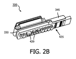
[030] 図2Aは、プリント回路基板(PCB)435の上部の等角図である。PCB435は、導体437を含む。図2Bは、インターポーザ330に対接して配置されたPCB435を具備したプローブ300の底部の等角図である。PCB435は、回路439を含み得る。回路439は、導体437に電気的に結合され得る。PCB435がインターポーザ330に対接して配置されたとき、導体437のうちの1つ又は複数は、インターポーザ330の導体335に電気的に結合され得る。図2Bに示される実施形態において、トランスデューサ取り付け部315のフランジ345は、PCB435をインターポーザ330に対して位置決めするように構成され得る。
FIG. 2A is an isometric view of the top of a printed circuit board (PCB) 435.
[031] 図3Aは、PCB435に対接して配置された本開示の実施形態によるボルスタープレート550を具備したプローブ300の底部の等角図である。図3Bは、ボルスタープレート550を具備したプローブ300の側面図である。ボルスタープレート550は、インターポーザ330に対して均一な圧力を印加するような大きさに形成され得る。いくつかの実施形態において、ボルスタープレートは、PCB435に隣接し得、インターポーザ330を介してフレキシブル回路325に電気的に接触するようにPCB435を保持し得る。いくつかの実施形態において、ボルスタープレート550は、ボルスタープレート550のベース部552から延在するリップ560を有し得る。リップ560は、プローブの1つ又は複数のコンポーネントを完全に又は部分的に包囲し得る。図3A〜図3Bに図示されるように、リップ560はプローブ300の一部分、例えばPCB435の一部分を部分的に包囲する。いくつかの実施形態において、リップ560は、組み付け中にコンポーネントを整列させるために使用され得る。ボルスタープレート550は、1つ又は複数のタブ555を含み得る。タブ555は、ボルスタープレート550のベース部552及び/又はリップ560から延在し得る。図3A〜図3Bにおいては2つのタブ555が図示されているが、ボルスタープレート550は、プローブ300の他方側に2つの追加的なタブを含んでよい。追加的なタブは、タブ555と対称になるように整列し得る。タブ555は、トランスデューサ取り付け部315、インターポーザ330及びPCB435を整列させるように構成され得る。例えば、タブ555は、トランスデューサ取り付け部315、インターポーザ330及びPCB435の側部に対接して設けられ、トランスデューサ取り付け部315、インターポーザ330及びPCB435の横向きの動きを防止するように配置された平坦な面を有し得る。図3A及び図3Bに示された実施形態において、タブ555は、トランスデューサ取り付け部315、インターポーザ330及びPCB435の長手方向側部に対接して設けられた面を有する。いくつかの実施形態において、タブ555は、トランスデューサ取り付け部のノッチ317内に配置されるように構成される。結果として、段部分323は、タブ555の間に設けられる。ノッチ317内のタブ555及びタブ555の間の段部分323の構成は、プローブ300の組み付けを更に容易にし得、トランスデューサ取り付け部315、インターポーザ330及びPCB435の動きを更に防止し得る。各タブ555は、開口551を含み得る。開口551は、トランスデューサ取り付け部315の開口341と整列するように配置され得る。いくつかの実施形態において、タブ555は省略され得、リップ560が、トランスデューサ取り付け部315の一部分を少なくとも部分的に包囲するように延在し得る。リップ560は、トランスデューサ取り付け部315、インターポーザ330及びPCB435のうちの1つ又は複数の側部に対接して配置された面を含み得る。リップ560は、トランスデューサ取り付け部315の開口341と整列した開口を含み得る。
[031] FIG. 3A is an isometric view of the bottom of a
[032] 図4A〜図4Bは、本開示の実施形態による、留め具670によってトランスデューサ取り付け部315に固定されたボルスタープレート550を具備した超音波プローブ300の概略図である。留め具670は、開口551及びトランスデューサ取り付け部315の開口を貫通し得る。図4Bは、プローブ300に装着された留め具670を図示する。留め具670は、ボルスタープレートが、プリント回路基板435、インターポーザ330及びフレキシブル回路325をトランスデューサ取り付け部315に対して圧縮することを維持するために使用され得る。種々の留め具が、留め具670として使用され得る。使用され得る留め具は、限定的ではないが、ピン、ネジ及びコイルバネピンを含む。コイルバネピンは、衝撃及び/又は振動を吸収し得、タブ及びトランスデューサ取り付け部の開口の周縁の周りに均等な応力分布、及び/又は一定の半径方向の力を与え得る。留め具670は、種々の手法を使用して所定の位置に保持され得る。例えば、留め具670は、摩擦、圧縮及び/又は接着剤によって所定の位置に保持され得る。いくつかの実施形態において、留め具670は、タブ655の外側面と面一であってよい。
[032] FIGS. 4A-4B are schematic views of an
[033] 図5は、本開示の実施形態による超音波プローブ300の一部分の側部の概略図である。いくつかの実施形態において、ボルスタープレート550(図5おいては不図示)のタブ555は、ボルスタープレート550が配置されたときにトランスデューサ取り付け部315の開口341からオフセットされている開口551を有し得る。開口341と開口551との間のオフセット701は、矢印によって示される2つの線によって示される。ボルスタープレート550は、オフセット701を除去し、開口341、551を整列させるために、PCB板435に対して圧縮され得る。次いで、ボルスタープレート550を所定の位置に固定するために、留め具(不図示)が開口341、551に挿入され得る。開口341と開口551との間の初期オフセット701は、ボルスタープレート550が、インターポーザ330を介してPCB板435とフレキシブル回路325との間の電気的結合を提供し得る圧縮力を維持することを可能にし得る。いくつかの実施形態において、インターポーザ330の上側面331及び下側面332上の導体335は、オフセット701の除去を可能にするために圧縮可能であってよい。図5の実施形態は、タブ555の長さに沿った方向のオフセットを示しているが、他の実施形態は、別の方向、例えば、タブ555の長さ方向に対してある角度を有する方向に沿ったオフセットを有し得る。
[033] FIG. 5 is a schematic side view of a portion of an
[034] 図6は、本開示の別の実施形態による、トランスデューサ取り付け部815を含む超音波プローブ300の一部分の概略的な側面図である。いくつかの実施形態において、トランスデューサ取り付け部815の上部に開口したU字形状スロット841が、プローブ300に含まれ得る。いくつかの超音波プローブ構成において、U字形状スロット841は、トランスデューサ取り付け部815によって包囲された穴、例えば図5に図示された開口341よりも作成が容易であり得る。ボルスタープレート550(図6においては不図示)のタブ555における開口551は、U字形状スロット841と整列するように配置され得る。いくつかの実施形態において、U字形状スロット841及び開口551は、図5を参照して説明されたものと同様のやり方でボルスタープレートが留め具(不図示)によって固定されたときに圧縮を提供するために、オフセットされ得る。
[034] FIG. 6 is a schematic side view of a portion of an
[035] 図1〜図6において示された実施形態において、ボルスタープレートは、留め具のために電気的コンポーネントの表面積を犠牲にすることなくフレキシブル回路をPCBに結合するためにインターポーザが利用されることを可能にし得る。ボルスタープレートは、留め具がトランスデューサのコンポーネント及び/又は音響路からオフセットされることを可能にし得る。いくつかの実施形態において、ボルスタープレートは、トランスデューサからの熱の放散を増大させ得る。ボルスタープレートは、金属、剛性プラスチック及び/又は他の適切な材料として実現され得る。いくつかの実施形態において、タブ及び/又はリップは、ボルスタープレートのベース部とは異なる材料を含み得る。ボルスタープレートは、組み付け中のコンポーネントの整列を容易にし得る追加的なフランジ、タブ及び/又はリブを含み得る。フランジ、タブ及び/又はリブは、ボルスタープレートの上側面、下側面及び/又は側部にあってよい。いくつかの実施形態において、PCB板に隣接するボルスタープレートの上側面は、インターポーザに印加される圧力の均一性を向上するためにパターンが形成され得る。 [035] In the embodiment shown in FIGS. 1-6, the bolster plate is utilized with an interposer to couple the flexible circuit to the PCB without sacrificing the surface area of the electrical components for the fasteners. Can make it possible. The bolster plate may allow the fasteners to be offset from the transducer components and / or the acoustic path. In some embodiments, the bolster plate can increase heat dissipation from the transducer. The bolster plate can be realized as metal, rigid plastic and / or other suitable material. In some embodiments, the tab and / or lip may comprise a different material than the base of the bolster plate. The bolster plate may include additional flanges, tabs and / or ribs that may facilitate alignment of the components during assembly. The flange, tab and / or rib may be on the upper side, lower side and / or side of the bolster plate. In some embodiments, the upper surface of the bolster plate adjacent to the PCB board can be patterned to improve the uniformity of the pressure applied to the interposer.
[036] 図7A〜図7Bは、本発明の実施形態による超音波プローブ300の概略図である。図7Aは、プローブ300の上部の等角図であり、図7Bは、プローブ300の遠位端部の側面図である。プローブ300は、保護シェル920によって包囲される。保護シェル920は、金属、ポリマー又は他の適切な材料であってよい。いくつかの実施形態において、保護シェル920は、ボルスタープレート550のための二次的な固定機構として働くように構成され得る。いくつかの実施形態において、保護シェル920は、プローブ300の内部コンポーネントを、湿気、電気的干渉、ほこり及び/又は生物学的汚染から保護し得る。
7A to 7B are schematic views of an
[037] 本開示のプローブの実施形態は、TEE超音波プローブとして使用され得る。TEE超音波プローブはしばしば、屈曲性の内視鏡タイプのデバイスの遠位端部に実装される。TEE超音波プローブは、撮像のための配置のために身体内の蛇行性の空洞を通って誘導され得る。例えば、TEEプローブは、食道に下向きに挿入され得、そこから超音波トランスデューサが、画像診断及び/又は医療手順(例えば、ステント留置)の監視のために心臓をスキャンし得る。外部超音波プローブとは異なり、TEEプローブは、心臓の視像を不明瞭にする胸壁、肋骨又は肺に対処する必要はない。図1〜図7に示されるプローブなどのインターポーザを使用して実現されるTEE超音波プローブは、より安価に製造され得、及び/又は臨床環境における信頼性がより高くなり得る。インターポーザの使用は、必要とされる半田接続の数を減らし得、回路の間の半田不良の数を減らし得る。ボルスタープレートは、信頼性の高い圧縮を提供して、TEEプローブの操作中にインターポーザを介した電気的接続を維持し得る。PCBは第2のフレキシブル回路よりも堅牢であり得、プローブの操作中のひび割れのリスクを減少させる。PCBは、フレキシブル回路よりも多数の及び/又は多種の電気的回路を提供することができる。 [037] Embodiments of the probes of the present disclosure may be used as TEE ultrasound probes. A TEE ultrasound probe is often implemented at the distal end of a flexible endoscopic type device. The TEE ultrasound probe can be guided through a serpentine cavity in the body for placement for imaging. For example, a TEE probe can be inserted downward into the esophagus, from which an ultrasound transducer can scan the heart for diagnostic imaging and / or monitoring of medical procedures (eg, stent placement). Unlike external ultrasound probes, TEE probes do not have to deal with the chest wall, ribs or lungs that obscure the heart image. A TEE ultrasound probe implemented using an interposer such as the probe shown in FIGS. 1-7 may be manufactured cheaper and / or may be more reliable in a clinical environment. The use of an interposer can reduce the number of solder connections required and can reduce the number of solder failures between circuits. The bolster plate can provide reliable compression to maintain electrical connection through the interposer during operation of the TEE probe. The PCB can be more robust than the second flexible circuit, reducing the risk of cracking during probe operation. PCBs can provide more and / or more types of electrical circuits than flexible circuits.
[038] インターポーザを使用して実現されるTEE超音波プローブが修理されるとき、2つのフレキシブル回路を有する従来のTEEプローブよりも素早く、安価に分解され得る。いくつかの実施形態において、コンポーネントの半田除去の必要がなくなり得る。留め具がボルスタープレートタブ及びトランスデューサ取り付け部から除去され得、ボルスタープレートも除去され、次いで残りのコンポーネントが分離され得る。いったん分離されたなら、個別のコンポーネントは修理、保留又は交換され得る。次いで、TEEプローブは、図3を参照して説明されたように再び組み付けられ得、臨床での使用に戻され得る。 [038] When a TEE ultrasound probe implemented using an interposer is repaired, it can be disassembled faster and cheaper than a conventional TEE probe with two flexible circuits. In some embodiments, it may not be necessary to desolder the component. The fasteners can be removed from the bolster plate tab and transducer mount, the bolster plate can also be removed, and then the remaining components can be separated. Once separated, individual components can be repaired, held or replaced. The TEE probe can then be reassembled as described with reference to FIG. 3 and returned to clinical use.
[039] TEE超音波プローブを参照して本開示の実施形態が説明されたが、本開示の実施形態は、例えば、カテーテル超音波プローブなどの限定的なプローブ外形寸法が望まれ得る場で撮像を行うように構成された他の超音波プローブにも拡張可能であるとも想定される。それ故、本システムは、限定的ではないが、腎臓、精巣、乳房、卵巣、子宮、甲状腺、肝臓、肺、筋骨格、脾臓、心臓、動脈及び血管系に関する画像情報の取得及び/又は記録を行うために使用され得る。 [039] Although embodiments of the present disclosure have been described with reference to a TEE ultrasound probe, embodiments of the present disclosure can be used in imaging where limited probe dimensions such as, for example, a catheter ultrasound probe may be desired. It is also envisioned that it can be extended to other ultrasound probes configured to perform. Therefore, the system can capture and / or record image information regarding, but not limited to, kidney, testis, breast, ovary, uterus, thyroid, liver, lung, musculoskeletal, spleen, heart, artery and vasculature. Can be used to do.
[040] 更に、本システム、装置及び方法は、インターポーザが望まれ得る任意の小部分撮像に拡張され得る。適切な超音波撮像システムは、例えば小部分撮像に適切な従来の広帯域線形アレイ、2次元アレイ及び/又は3次元アレイトランスデューサに対応し得る、Philips(登録商標)の超音波システムを含み得る。 [040] In addition, the present systems, devices and methods can be extended to any sub-imaging where an interposer may be desired. Suitable ultrasound imaging systems may include Philips® ultrasound systems, which may accommodate, for example, conventional broadband linear arrays, two-dimensional arrays, and / or three-dimensional array transducers suitable for small-part imaging.
[041] 本開示の実施形態による超音波プローブを含み得る例示的な超音波システムが、図8に示される。撮像システム10は、経食道検査(TEE)システムであってよい。撮像システム10は、ケーブル16によって接続されたプローブハンドル14を具備するTEEプローブ12と、張力緩和部17と、電子ボックス20へのコネクタ18とを含み得る。いくつかの実施形態において、TEEプローブ12は、図7A〜図7Bに示された超音波プローブ300を使用して実現され得る。電子ボックス20は、キーボード22とインターフェースし得、映像表示器24に画像信号を供給し得る。電子ボックス20は、送信ビーム形成器と、受信ビーム形成器と、画像生成器とを含み得る。電子ボックス20は、3次元画像のためのボリュームレンダラー(volume renderer)、映像表示器24の追加的な表示要素のためのグラフィックスプロセッサ及び/又はドプラ撮像のためのB−モードプロセッサを更に含み得る。TEEプローブ12は、細長状の屈曲性又は半屈曲性の本体部36に接続された遠位部30を有し得る。細長状部36の近位端部は、プローブハンドル14の遠位端部に接続され得る。プローブ12の遠位部30は、剛性領域32と屈曲性領域34とを含み得、屈曲性領域34は細長状本体部36の遠位端部に接続され得る。プローブハンドル14は、屈曲性領域34の関節を作動させ、それによって剛性領域32を関心対象の組織に配向する位置制御器15を含み得る。細長状の半屈曲性本体部36は、食道への挿入のために構築され、配置され得る。
[041] An exemplary ultrasound system that may include an ultrasound probe according to an embodiment of the present disclosure is shown in FIG. The
[042] 図9は、本開示の実施形態に従って使用されるTEEプローブ1112の概略図である。TEEプローブ1112は、図8に示されるTEEプローブ12及び撮像システム10を使用して実現され得る。臨床医は、導入器1135によって、TEEプローブ1112を口1130、咽頭喉頭部1132を通って食道1380内に導入し得る。プローブ及び導入器を口蓋垂1133よりも奥まで移動させた後、プローブ1112の遠位部50は、所望の場所に置いて胃腸(GI)管の内部に配置される。代替的には、臨床医はプローブ1112を鼻腔1134を通って食道1380に導入する。トランスデューサアレイ42を具備した遠位部50は、図示されるように食道1380内に、又は胃1381の基底部に配置され得る。心臓1390を撮像するために、送信ビーム形成器は、送出されたパルスの焦点を所望の深度に合わせ、受信ビーム形成器は、胸郭内の構造からのエコーを検知する。
[042] FIG. 9 is a schematic diagram of a
[043] 図10は、本発明の実施形態によるTEEプローブを使用する方法1200のフローチャートである。いくつかの実施形態において、この方法は、図9に示されたTEEプローブ1112、又は図8に示されたTEEプローブ12及び撮像システム10を使用して実行されてよい。ステップ1205において、TEEプローブは、口又は鼻を通って患者内に導入され得る。次いで、ステップ1210において、臨床医はTEEプローブを咽頭喉頭部を通って誘導し得る。次いで、ステップ1215において、TEEプローブは患者の食道内へと誘導され得る。食道内に入ると、ステップ1220において、TEEプローブはGI管内の所望の場所(例えば、食道、胃の一部分)に配置され得る。次いで、ステップ1225において、臨床医は、TEEプローブを使用して超音波画像を取得し得る。この画像は、心臓、別の臓器及び/又は医療デバイスのものであってよい。いくつかの実施形態において、超音波画像はステップ1205〜ステップ1220の間に取得されてもよい。TEEプローブの移動中の画像の取得は、プローブの誘導及び/又は配置を補助し得る。
[043] FIG. 10 is a flowchart of a
[044] 本発明の特定の追加的な利点及び特徴は、本開示を検討することで当業者には明らかであり得、又は本発明の新規なシステム及び方法を用いた者によって経験され得、その主なものは、より信頼性の高いTEE及びカテーテル超音波デバイス及びその動作の方法が提供されることである。本システム及び方法の別の利点は、従来の医療画像システムが、本システム、デバイス及び方法の特徴及び利点を組み込むように、容易にアップグレードされ得るということである。 [044] Certain additional advantages and features of the invention may be apparent to those of ordinary skill in the art upon reviewing the present disclosure, or may be experienced by those using the novel systems and methods of the invention, The main thing is to provide a more reliable TEE and catheter ultrasound device and method of operation thereof. Another advantage of the system and method is that conventional medical imaging systems can be easily upgraded to incorporate the features and advantages of the system, device and method.
[045] 当然のことであるが、上記の実施形態又はプロセスのうちの任意の1つは、1つ又は複数の他の実施形態及び/又はプロセスと組み合わせされ得ること、又は本システム、デバイス及び方法に従った別個のデバイス又はデバイスの部分の間で分割され及び/又は実行され得ることを理解されたい。 [045] It will be appreciated that any one of the above embodiments or processes may be combined with one or more other embodiments and / or processes, or the system, device and It should be understood that it may be divided and / or performed between separate devices or parts of devices according to the method.
[046] 最後に、前述の議論は、本システムの単なる例示であることを意図し、添付の特許請求の範囲を任意の特定の実施形態又は実施形態の集合に限定するものであると解釈されるべきではない。従って、本システムは、例示的な実施形態を参照して特に詳細に説明されたが、数多くの修正及び代替実施形態が、以下の特許請求の範囲において記載される本システムより広範な意図された趣旨及び範囲から逸脱することなく当業者によって考案され得ることも理解されたい。それ故、本明細書及び図面は例示的なものであると見なされるべきであり、添付の特許請求の範囲を限定することを意図するものではない。 [046] Finally, the foregoing discussion is intended to be merely illustrative of the present system and is to be construed as limiting the appended claims to any particular embodiment or collection of embodiments. Should not. Thus, although the system has been described in particular detail with reference to exemplary embodiments, numerous modifications and alternative embodiments are intended to be broader than the system described in the following claims. It should also be understood that those skilled in the art can devise without departing from the spirit and scope. The specification and drawings are accordingly to be regarded in an illustrative manner and are not intended to limit the scope of the appended claims.
Claims (17)
前記トランスデューサ取り付け部の上側面に結合されたトランスデューサスタックと、
前記トランスデューサスタックに結合されて、前記トランスデューサ取り付け部の下方に巻き付けられたフレキシブル回路であって、前記トランスデューサ取り付け部の下側面の一部分を覆うフレキシブル回路と、
前記トランスデューサ取り付け部の前記下側面の反対側で前記フレキシブル回路に隣接するインターポーザと、
前記フレキシブル回路の反対側で前記インターポーザに隣接するプリント回路基板と、
前記プリント回路基板に隣接するボルスタープレートであって、前記トランスデューサ取り付け部に固定され、前記インターポーザを介して前記フレキシブル回路に電気的に接触するように前記プリント回路基板を保持するボルスタープレートと
を備える、超音波プローブ。 A transducer mounting;
A transducer stack coupled to the upper side of the transducer mounting;
A flexible circuit coupled to the transducer stack and wound below the transducer mount, the flexible circuit covering a portion of the lower surface of the transducer mount;
An interposer adjacent to the flexible circuit on the opposite side of the lower surface of the transducer mounting;
A printed circuit board adjacent to the interposer on the opposite side of the flexible circuit;
A bolster plate adjacent to the printed circuit board, the bolster plate being fixed to the transducer mounting portion and holding the printed circuit board so as to be in electrical contact with the flexible circuit via the interposer, Ultrasonic probe.
インターポーザを、前記フレキシブル回路に対接して配置するステップと、
プリント回路基板を、前記インターポーザに対接して配置するステップと、
ボルスタープレートによって、前記プリント回路基板、前記インターポーザ及び前記フレキシブル回路を前記トランスデューサ取り付け部に対して圧縮するステップと、
前記ボルスタープレートを前記トランスデューサ取り付け部に結合するステップと
を含む、方法。 Winding a flexible circuit coupled to the transducer stack below a transducer mounting coupled to the transducer stack;
Placing an interposer against the flexible circuit;
Placing a printed circuit board against the interposer;
Compressing the printed circuit board, the interposer, and the flexible circuit with respect to the transducer mounting portion by a bolster plate;
Coupling the bolster plate to the transducer mount.
Applications Claiming Priority (3)
| Application Number | Priority Date | Filing Date | Title |
|---|---|---|---|
| US201562102656P | 2015-01-13 | 2015-01-13 | |
| US62/102,656 | 2015-01-13 | ||
| PCT/IB2016/050004 WO2016113638A1 (en) | 2015-01-13 | 2016-01-02 | Interposer electrical interconnect coupling methods, apparatuses, and systems |
Publications (3)
| Publication Number | Publication Date |
|---|---|
| JP2018501041A JP2018501041A (en) | 2018-01-18 |
| JP2018501041A5 JP2018501041A5 (en) | 2018-10-11 |
| JP6487052B2 true JP6487052B2 (en) | 2019-03-20 |
Family
ID=55273302
Family Applications (1)
| Application Number | Title | Priority Date | Filing Date |
|---|---|---|---|
| JP2017536803A Active JP6487052B2 (en) | 2015-01-13 | 2016-01-02 | Interposer electrical interconnect coupling method, apparatus and system |
Country Status (5)
| Country | Link |
|---|---|
| US (2) | US11484291B2 (en) |
| EP (1) | EP3244804B1 (en) |
| JP (1) | JP6487052B2 (en) |
| CN (1) | CN107106136B (en) |
| WO (1) | WO2016113638A1 (en) |
Families Citing this family (10)
| Publication number | Priority date | Publication date | Assignee | Title |
|---|---|---|---|---|
| GB2530036A (en) | 2014-09-09 | 2016-03-16 | Ultrahaptics Ltd | Method and apparatus for modulating haptic feedback |
| US10818162B2 (en) | 2015-07-16 | 2020-10-27 | Ultrahaptics Ip Ltd | Calibration techniques in haptic systems |
| EP3519109B1 (en) | 2016-10-03 | 2023-12-06 | Koninklijke Philips N.V. | Intra-cardiac echocardiography interposer |
| US11360546B2 (en) | 2017-12-22 | 2022-06-14 | Ultrahaptics Ip Ltd | Tracking in haptic systems |
| KR20200109906A (en) * | 2019-03-15 | 2020-09-23 | 삼성메디슨 주식회사 | Ultrasound diagnositic apparatus and controlling method of the ultrasound diagnositic apparatus |
| US11374586B2 (en) | 2019-10-13 | 2022-06-28 | Ultraleap Limited | Reducing harmonic distortion by dithering |
| DE112022004581T5 (en) * | 2021-10-22 | 2024-09-19 | Veran Medical Technologies, Inc. | LOW PROFILE ULTRASOUND CATHETER AND SYSTEM |
| CN114190978B (en) * | 2021-11-25 | 2024-07-09 | 中国科学院深圳先进技术研究院 | Array ultrasonic transducer and manufacturing method and assembly device thereof |
| US20240129655A1 (en) * | 2022-10-11 | 2024-04-18 | Ultraleap Limited | Acoustic Transducer Mounts |
| WO2024260811A1 (en) * | 2023-06-22 | 2024-12-26 | Koninklijke Philips N.V. | Disposable transesophageal echocardiogram (tee) probe |
Family Cites Families (26)
| Publication number | Priority date | Publication date | Assignee | Title |
|---|---|---|---|---|
| JPS5968510U (en) * | 1982-10-27 | 1984-05-09 | 松下電器産業株式会社 | ultrasonic probe |
| JP2802667B2 (en) * | 1990-04-26 | 1998-09-24 | 日本電波工業株式会社 | Ultrasonic probe |
| NL9001755A (en) | 1990-08-02 | 1992-03-02 | Optische Ind De Oude Delft Nv | ENDOSCOPIC SCANNER. |
| US5882310A (en) | 1997-12-01 | 1999-03-16 | Acuson Corporation | Ultrasound transducer connector and multiport imaging system receptacle arrangement |
| US6733457B2 (en) | 2002-06-11 | 2004-05-11 | Vermon | Motorized multiplane transducer tip apparatus with transducer locking |
| AU2003280172A1 (en) * | 2002-12-11 | 2004-06-30 | Koninklijke Philips Electronics N.V. | Miniaturized ultrasonic transducer |
| US7066887B2 (en) * | 2003-10-21 | 2006-06-27 | Vermon | Bi-plane ultrasonic probe |
| US20070075717A1 (en) * | 2005-09-14 | 2007-04-05 | Touchdown Technologies, Inc. | Lateral interposer contact design and probe card assembly |
| WO2009083896A2 (en) * | 2007-12-27 | 2009-07-09 | Koninklijke Philips Electronics, N.V. | Ultrasound transducer assembly with improved thermal behavior |
| US20100249598A1 (en) | 2009-03-25 | 2010-09-30 | General Electric Company | Ultrasound probe with replaceable head portion |
| US8264126B2 (en) | 2009-09-01 | 2012-09-11 | Measurement Specialties, Inc. | Multilayer acoustic impedance converter for ultrasonic transducers |
| US8932238B2 (en) * | 2009-09-29 | 2015-01-13 | Liposonix, Inc. | Medical ultrasound device with liquid dispensing device coupled to a therapy head |
| JP2014502201A (en) * | 2010-12-03 | 2014-01-30 | リサーチ・トライアングル・インスティチュート | Ultrasonic device forming method and related apparatus |
| CN103533896B (en) * | 2011-05-17 | 2016-01-06 | 皇家飞利浦有限公司 | There is the matrix ultrasonic probe that passive heat dissipates |
| US20130085394A1 (en) * | 2011-10-04 | 2013-04-04 | Sonivate Medical, Inc. | Glove with integrated sensor |
| JP6091755B2 (en) * | 2012-01-24 | 2017-03-08 | 東芝メディカルシステムズ株式会社 | Ultrasonic probe and ultrasonic diagnostic apparatus |
| US9072487B2 (en) * | 2012-05-11 | 2015-07-07 | General Electric Company | Ultrasound probe thermal drain |
| US20140046188A1 (en) * | 2012-08-07 | 2014-02-13 | Jesse T. Yen | System and Method for Ultrasonic Diagnostics |
| JP2014057136A (en) | 2012-09-11 | 2014-03-27 | Hitachi Aloka Medical Ltd | Ultrasonic probe |
| US9490240B2 (en) | 2012-09-28 | 2016-11-08 | Intel Corporation | Film interposer for integrated circuit devices |
| JP5550706B2 (en) * | 2012-10-31 | 2014-07-16 | 日立アロカメディカル株式会社 | Ultrasonic probe |
| JP5529313B1 (en) * | 2013-03-05 | 2014-06-25 | 日立アロカメディカル株式会社 | Ultrasonic probe |
| WO2014160291A1 (en) * | 2013-03-13 | 2014-10-02 | Maui Imaging, Inc. | Alignment of ultrasound transducer arrays and multiple aperture probe assembly |
| US20150087988A1 (en) * | 2013-09-20 | 2015-03-26 | General Electric Company | Ultrasound transducer arrays |
| US9127504B2 (en) * | 2013-10-30 | 2015-09-08 | C. R. Laurence Co., Inc. | Corner assembly for metal framed glass panel doors, windows and wall partitions |
| JP6281262B2 (en) * | 2013-11-29 | 2018-02-21 | セイコーエプソン株式会社 | Ultrasonic device and probe, electronic apparatus and ultrasonic imaging apparatus |
-
2016
- 2016-01-02 US US15/541,732 patent/US11484291B2/en active Active
- 2016-01-02 EP EP16702446.2A patent/EP3244804B1/en active Active
- 2016-01-02 WO PCT/IB2016/050004 patent/WO2016113638A1/en active Application Filing
- 2016-01-02 CN CN201680005680.3A patent/CN107106136B/en active Active
- 2016-01-02 JP JP2017536803A patent/JP6487052B2/en active Active
-
2022
- 2022-09-29 US US17/956,316 patent/US20230015499A1/en active Pending
Also Published As
| Publication number | Publication date |
|---|---|
| US11484291B2 (en) | 2022-11-01 |
| EP3244804A1 (en) | 2017-11-22 |
| CN107106136B (en) | 2020-09-22 |
| EP3244804B1 (en) | 2018-12-12 |
| CN107106136A (en) | 2017-08-29 |
| US20230015499A1 (en) | 2023-01-19 |
| WO2016113638A1 (en) | 2016-07-21 |
| JP2018501041A (en) | 2018-01-18 |
| US20180271494A1 (en) | 2018-09-27 |
Similar Documents
| Publication | Publication Date | Title |
|---|---|---|
| JP6487052B2 (en) | Interposer electrical interconnect coupling method, apparatus and system | |
| JP4429012B2 (en) | Ultrasonic probe wiring method and apparatus | |
| CN102462510B (en) | Rotary ultrasonic imaging system | |
| JP5973761B2 (en) | Cable connection structure | |
| EP2425783A1 (en) | Probe for ultrasonic diagnostic apparatus | |
| JP6622292B2 (en) | Low profile circuit board connector for imaging system | |
| JP2006510269A (en) | Ultra-small ultrasonic transducer | |
| US10292680B2 (en) | Ultrasonic probe and manufacturing method thereof | |
| JP2008295749A (en) | Ultrasonic endoscope and ultrasonic endoscope apparatus | |
| US20080119738A1 (en) | Ultrasound Endoscope | |
| CN117355259A (en) | Ultrasound imaging probe with improved heat dissipation | |
| CN102451021B (en) | Tissue insertion type ultrasonic probe | |
| WO2020139645A2 (en) | Transducer-mounted needle assembly with improved electrical connection to power source | |
| JP6629333B2 (en) | Interposer electrical interconnect with spring | |
| JP7079840B2 (en) | Medical Imaging Device Connector Assembly | |
| US11986351B2 (en) | Flexible electric circuit for ultrasound catheters and related devices and methods | |
| JP6132963B2 (en) | Cable connection structure, ultrasound probe and ultrasound endoscope system | |
| EP4344653A1 (en) | Ultrasound endoscopy | |
| JP7395277B2 (en) | Signal transmission wiring connection unit, endoscope, method for manufacturing signal transmission wiring connection unit, and ultrasonic transducer module | |
| US20190133555A1 (en) | Ultrasonic transducer module and ultrasonic endoscope | |
| WO2022074776A1 (en) | Signal transmission wiring connection unit, endoscope, method for manufacturing signal transmission wiring connection unit, and ultrasound oscillator module | |
| US20200205781A1 (en) | Miniscule Transducer for a Medical Article | |
| CN117770879A (en) | Ultrasonic endoscopy | |
| CN112868137A (en) | Electronic component of interventional medical device | |
| CN112384148A (en) | Wire connection in ultrasound imaging devices, systems, and methods |
Legal Events
| Date | Code | Title | Description |
|---|---|---|---|
| A521 | Request for written amendment filed |
Free format text: JAPANESE INTERMEDIATE CODE: A523 Effective date: 20180830 |
|
| A621 | Written request for application examination |
Free format text: JAPANESE INTERMEDIATE CODE: A621 Effective date: 20180830 |
|
| A871 | Explanation of circumstances concerning accelerated examination |
Free format text: JAPANESE INTERMEDIATE CODE: A871 Effective date: 20180830 |
|
| A975 | Report on accelerated examination |
Free format text: JAPANESE INTERMEDIATE CODE: A971005 Effective date: 20180921 |
|
| A131 | Notification of reasons for refusal |
Free format text: JAPANESE INTERMEDIATE CODE: A131 Effective date: 20181002 |
|
| A521 | Request for written amendment filed |
Free format text: JAPANESE INTERMEDIATE CODE: A523 Effective date: 20181217 |
|
| TRDD | Decision of grant or rejection written | ||
| A01 | Written decision to grant a patent or to grant a registration (utility model) |
Free format text: JAPANESE INTERMEDIATE CODE: A01 Effective date: 20190122 |
|
| A61 | First payment of annual fees (during grant procedure) |
Free format text: JAPANESE INTERMEDIATE CODE: A61 Effective date: 20190220 |
|
| R150 | Certificate of patent or registration of utility model |
Ref document number: 6487052 Country of ref document: JP Free format text: JAPANESE INTERMEDIATE CODE: R150 |
|
| R250 | Receipt of annual fees |
Free format text: JAPANESE INTERMEDIATE CODE: R250 |
|
| R250 | Receipt of annual fees |
Free format text: JAPANESE INTERMEDIATE CODE: R250 |
|
| R250 | Receipt of annual fees |
Free format text: JAPANESE INTERMEDIATE CODE: R250 |