JP6478999B2 - Distal front end for position adjustment of endoscope with suction device - Google Patents
Distal front end for position adjustment of endoscope with suction device Download PDFInfo
- Publication number
- JP6478999B2 JP6478999B2 JP2016528831A JP2016528831A JP6478999B2 JP 6478999 B2 JP6478999 B2 JP 6478999B2 JP 2016528831 A JP2016528831 A JP 2016528831A JP 2016528831 A JP2016528831 A JP 2016528831A JP 6478999 B2 JP6478999 B2 JP 6478999B2
- Authority
- JP
- Japan
- Prior art keywords
- inlet
- lumen
- distal
- endoscope
- wall
- Prior art date
- Legal status (The legal status is an assumption and is not a legal conclusion. Google has not performed a legal analysis and makes no representation as to the accuracy of the status listed.)
- Active
Links
- 238000004140 cleaning Methods 0.000 claims description 96
- 210000001072 colon Anatomy 0.000 claims description 65
- 239000000523 sample Substances 0.000 claims description 60
- 239000012530 fluid Substances 0.000 claims description 42
- 239000002699 waste material Substances 0.000 claims description 31
- 238000002052 colonoscopy Methods 0.000 claims description 19
- 230000002496 gastric effect Effects 0.000 claims description 13
- 238000003384 imaging method Methods 0.000 claims description 12
- 210000001035 gastrointestinal tract Anatomy 0.000 claims description 5
- 238000007599 discharging Methods 0.000 claims 1
- 230000008901 benefit Effects 0.000 description 36
- 230000000968 intestinal effect Effects 0.000 description 30
- 238000000034 method Methods 0.000 description 27
- 238000003780 insertion Methods 0.000 description 15
- 230000037431 insertion Effects 0.000 description 15
- 239000002245 particle Substances 0.000 description 15
- 230000006870 function Effects 0.000 description 12
- 239000000463 material Substances 0.000 description 10
- 210000002159 anterior chamber Anatomy 0.000 description 8
- 125000006850 spacer group Chemical group 0.000 description 7
- 238000005452 bending Methods 0.000 description 6
- 235000019589 hardness Nutrition 0.000 description 6
- 238000005286 illumination Methods 0.000 description 6
- 239000000853 adhesive Substances 0.000 description 5
- 230000001070 adhesive effect Effects 0.000 description 5
- 238000013459 approach Methods 0.000 description 5
- 238000004891 communication Methods 0.000 description 5
- 238000012546 transfer Methods 0.000 description 5
- 238000010586 diagram Methods 0.000 description 4
- 210000000936 intestine Anatomy 0.000 description 4
- 230000000670 limiting effect Effects 0.000 description 4
- 230000007246 mechanism Effects 0.000 description 4
- 230000003287 optical effect Effects 0.000 description 4
- 230000036961 partial effect Effects 0.000 description 4
- 230000004888 barrier function Effects 0.000 description 3
- 230000000903 blocking effect Effects 0.000 description 3
- 150000001875 compounds Chemical class 0.000 description 3
- 230000002262 irrigation Effects 0.000 description 3
- 238000003973 irrigation Methods 0.000 description 3
- 239000000203 mixture Substances 0.000 description 3
- 229920002635 polyurethane Polymers 0.000 description 3
- 239000004814 polyurethane Substances 0.000 description 3
- 230000002829 reductive effect Effects 0.000 description 3
- 208000024891 symptom Diseases 0.000 description 3
- 238000012360 testing method Methods 0.000 description 3
- 230000008859 change Effects 0.000 description 2
- 210000000887 face Anatomy 0.000 description 2
- 210000003608 fece Anatomy 0.000 description 2
- 239000002783 friction material Substances 0.000 description 2
- 238000002347 injection Methods 0.000 description 2
- 239000007924 injection Substances 0.000 description 2
- 238000002955 isolation Methods 0.000 description 2
- 239000007788 liquid Substances 0.000 description 2
- 238000004519 manufacturing process Methods 0.000 description 2
- 238000012986 modification Methods 0.000 description 2
- 230000004048 modification Effects 0.000 description 2
- 229920000642 polymer Polymers 0.000 description 2
- 238000000926 separation method Methods 0.000 description 2
- 229920002379 silicone rubber Polymers 0.000 description 2
- 239000004945 silicone rubber Substances 0.000 description 2
- 230000000472 traumatic effect Effects 0.000 description 2
- 238000012800 visualization Methods 0.000 description 2
- VRBFTYUMFJWSJY-UHFFFAOYSA-N 28804-46-8 Chemical compound ClC1CC(C=C2)=CC=C2C(Cl)CC2=CC=C1C=C2 VRBFTYUMFJWSJY-UHFFFAOYSA-N 0.000 description 1
- 208000032544 Cicatrix Diseases 0.000 description 1
- 206010018852 Haematoma Diseases 0.000 description 1
- 208000032843 Hemorrhage Diseases 0.000 description 1
- 208000031481 Pathologic Constriction Diseases 0.000 description 1
- 240000007711 Peperomia pellucida Species 0.000 description 1
- 239000004809 Teflon Substances 0.000 description 1
- 229920006362 Teflon® Polymers 0.000 description 1
- 230000009471 action Effects 0.000 description 1
- 239000002390 adhesive tape Substances 0.000 description 1
- 208000034158 bleeding Diseases 0.000 description 1
- 230000000740 bleeding effect Effects 0.000 description 1
- 238000009530 blood pressure measurement Methods 0.000 description 1
- 239000011248 coating agent Substances 0.000 description 1
- 238000000576 coating method Methods 0.000 description 1
- 230000000112 colonic effect Effects 0.000 description 1
- 230000001010 compromised effect Effects 0.000 description 1
- 230000021615 conjugation Effects 0.000 description 1
- 230000008602 contraction Effects 0.000 description 1
- 238000005520 cutting process Methods 0.000 description 1
- 230000007423 decrease Effects 0.000 description 1
- 230000007547 defect Effects 0.000 description 1
- 238000013461 design Methods 0.000 description 1
- 238000003745 diagnosis Methods 0.000 description 1
- 239000006185 dispersion Substances 0.000 description 1
- 238000006073 displacement reaction Methods 0.000 description 1
- 230000009977 dual effect Effects 0.000 description 1
- 239000000428 dust Substances 0.000 description 1
- 230000000694 effects Effects 0.000 description 1
- 229920001971 elastomer Polymers 0.000 description 1
- 238000005516 engineering process Methods 0.000 description 1
- 229920005570 flexible polymer Polymers 0.000 description 1
- 238000007654 immersion Methods 0.000 description 1
- 230000002401 inhibitory effect Effects 0.000 description 1
- 230000001788 irregular Effects 0.000 description 1
- 230000013011 mating Effects 0.000 description 1
- 230000000414 obstructive effect Effects 0.000 description 1
- 230000035515 penetration Effects 0.000 description 1
- 239000002861 polymer material Substances 0.000 description 1
- 239000002952 polymeric resin Substances 0.000 description 1
- 238000002360 preparation method Methods 0.000 description 1
- 230000008569 process Effects 0.000 description 1
- 230000001105 regulatory effect Effects 0.000 description 1
- 230000004044 response Effects 0.000 description 1
- 230000002441 reversible effect Effects 0.000 description 1
- 238000007665 sagging Methods 0.000 description 1
- 231100000241 scar Toxicity 0.000 description 1
- 230000037387 scars Effects 0.000 description 1
- 238000006748 scratching Methods 0.000 description 1
- 230000002393 scratching effect Effects 0.000 description 1
- 238000007789 sealing Methods 0.000 description 1
- 238000007493 shaping process Methods 0.000 description 1
- 239000007787 solid Substances 0.000 description 1
- 239000007921 spray Substances 0.000 description 1
- 238000005507 spraying Methods 0.000 description 1
- 230000007480 spreading Effects 0.000 description 1
- 238000003892 spreading Methods 0.000 description 1
- 230000036262 stenosis Effects 0.000 description 1
- 208000037804 stenosis Diseases 0.000 description 1
- 239000000725 suspension Substances 0.000 description 1
- 229920003002 synthetic resin Polymers 0.000 description 1
- 239000012780 transparent material Substances 0.000 description 1
- 210000002438 upper gastrointestinal tract Anatomy 0.000 description 1
- 230000002792 vascular Effects 0.000 description 1
- 230000000007 visual effect Effects 0.000 description 1
- XLYOFNOQVPJJNP-UHFFFAOYSA-N water Substances O XLYOFNOQVPJJNP-UHFFFAOYSA-N 0.000 description 1
Images


Classifications
-
- A—HUMAN NECESSITIES
- A61—MEDICAL OR VETERINARY SCIENCE; HYGIENE
- A61B—DIAGNOSIS; SURGERY; IDENTIFICATION
- A61B1/00—Instruments for performing medical examinations of the interior of cavities or tubes of the body by visual or photographical inspection, e.g. endoscopes; Illuminating arrangements therefor
- A61B1/00064—Constructional details of the endoscope body
- A61B1/00071—Insertion part of the endoscope body
- A61B1/0008—Insertion part of the endoscope body characterised by distal tip features
- A61B1/00089—Hoods
-
- A—HUMAN NECESSITIES
- A61—MEDICAL OR VETERINARY SCIENCE; HYGIENE
- A61B—DIAGNOSIS; SURGERY; IDENTIFICATION
- A61B1/00—Instruments for performing medical examinations of the interior of cavities or tubes of the body by visual or photographical inspection, e.g. endoscopes; Illuminating arrangements therefor
- A61B1/00064—Constructional details of the endoscope body
- A61B1/00071—Insertion part of the endoscope body
- A61B1/0008—Insertion part of the endoscope body characterised by distal tip features
- A61B1/00094—Suction openings
-
- A—HUMAN NECESSITIES
- A61—MEDICAL OR VETERINARY SCIENCE; HYGIENE
- A61B—DIAGNOSIS; SURGERY; IDENTIFICATION
- A61B1/00—Instruments for performing medical examinations of the interior of cavities or tubes of the body by visual or photographical inspection, e.g. endoscopes; Illuminating arrangements therefor
- A61B1/00064—Constructional details of the endoscope body
- A61B1/00071—Insertion part of the endoscope body
- A61B1/0008—Insertion part of the endoscope body characterised by distal tip features
- A61B1/00101—Insertion part of the endoscope body characterised by distal tip features the distal tip features being detachable
-
- A—HUMAN NECESSITIES
- A61—MEDICAL OR VETERINARY SCIENCE; HYGIENE
- A61B—DIAGNOSIS; SURGERY; IDENTIFICATION
- A61B1/00—Instruments for performing medical examinations of the interior of cavities or tubes of the body by visual or photographical inspection, e.g. endoscopes; Illuminating arrangements therefor
- A61B1/00112—Connection or coupling means
- A61B1/00121—Connectors, fasteners and adapters, e.g. on the endoscope handle
- A61B1/00128—Connectors, fasteners and adapters, e.g. on the endoscope handle mechanical, e.g. for tubes or pipes
-
- A—HUMAN NECESSITIES
- A61—MEDICAL OR VETERINARY SCIENCE; HYGIENE
- A61B—DIAGNOSIS; SURGERY; IDENTIFICATION
- A61B1/00—Instruments for performing medical examinations of the interior of cavities or tubes of the body by visual or photographical inspection, e.g. endoscopes; Illuminating arrangements therefor
- A61B1/00131—Accessories for endoscopes
- A61B1/0014—Fastening element for attaching accessories to the outside of an endoscope, e.g. clips, clamps or bands
-
- A—HUMAN NECESSITIES
- A61—MEDICAL OR VETERINARY SCIENCE; HYGIENE
- A61B—DIAGNOSIS; SURGERY; IDENTIFICATION
- A61B1/00—Instruments for performing medical examinations of the interior of cavities or tubes of the body by visual or photographical inspection, e.g. endoscopes; Illuminating arrangements therefor
- A61B1/012—Instruments for performing medical examinations of the interior of cavities or tubes of the body by visual or photographical inspection, e.g. endoscopes; Illuminating arrangements therefor characterised by internal passages or accessories therefor
- A61B1/015—Control of fluid supply or evacuation
-
- A—HUMAN NECESSITIES
- A61—MEDICAL OR VETERINARY SCIENCE; HYGIENE
- A61B—DIAGNOSIS; SURGERY; IDENTIFICATION
- A61B1/00—Instruments for performing medical examinations of the interior of cavities or tubes of the body by visual or photographical inspection, e.g. endoscopes; Illuminating arrangements therefor
- A61B1/31—Instruments for performing medical examinations of the interior of cavities or tubes of the body by visual or photographical inspection, e.g. endoscopes; Illuminating arrangements therefor for the rectum, e.g. proctoscopes, sigmoidoscopes, colonoscopes
Landscapes
- Health & Medical Sciences (AREA)
- Life Sciences & Earth Sciences (AREA)
- Surgery (AREA)
- Engineering & Computer Science (AREA)
- Biomedical Technology (AREA)
- Heart & Thoracic Surgery (AREA)
- Pathology (AREA)
- Radiology & Medical Imaging (AREA)
- Nuclear Medicine, Radiotherapy & Molecular Imaging (AREA)
- Biophysics (AREA)
- Physics & Mathematics (AREA)
- Optics & Photonics (AREA)
- Medical Informatics (AREA)
- Molecular Biology (AREA)
- Animal Behavior & Ethology (AREA)
- General Health & Medical Sciences (AREA)
- Public Health (AREA)
- Veterinary Medicine (AREA)
- Mechanical Engineering (AREA)
- Endoscopes (AREA)
Description
関連出願
本願は、米国特許法第119条(e)の下で、2013年11月21日に出願された米国仮特許出願第61/906,982号および2014年6月17日に出願された米国仮特許出願第62/012,997号に基づく優先権の利益を要求し、これらの内容全体を本明細書に引用により援用する。
RELATED APPLICATIONS This application was filed on US Provisional Patent Application Nos. 61 / 906,982 and June 17, 2014, filed on November 21, 2013 under US Patent Act 119 (e). Requests the benefit of priority based on US Provisional Patent Application No. 62 / 012,997, the entire contents of which are hereby incorporated by reference.
発明の分野と背景
本発明は、そのいくつかの実施形態において、内視鏡とともに使用される道具に関し、排他的にではなくより具体的には、内視鏡とともに体内の管腔に挿入され、体内の管腔をクリーニングすることにより、内視鏡による管腔の視覚化を容易にするために使用される、構成部品に関する。たとえば、いくつかの実施形態は、結腸内視鏡検査中のクリーニングのために結腸内視鏡とともに使用される場合がある。
FIELD OF THE INVENTION The present invention relates, in some embodiments, to a tool for use with an endoscope, more specifically, but not exclusively, inserted into a body lumen with an endoscope, The present invention relates to a component used to facilitate visualization of a lumen by an endoscope by cleaning the lumen in the body. For example, some embodiments may be used with a colonoscope for cleaning during colonoscopy.
結腸内視鏡検査中、洗浄作業用および排出作業用のパイプを用いて排泄物を結腸から除去する。一般的に、結腸内視鏡の洗浄路は、排泄物を緩くし、分解し、および/または細分化するための流体を、結腸に送り、作業通路がこの排泄物を排出する。 During colonoscopy, stool is removed from the colon using cleaning and drainage pipes. In general, the colonoscope wash channel sends fluid to the colon to loosen, disassemble and / or subdivide the waste, and the working passage discharges the waste.
結腸内視鏡プローブに洗浄路および/または排出路を追加したセルフクリーニングシステムが、たとえば、2009年5月20日出願の国際特許出願第2009/143201号および2010年12月2日出願の国際特許出願第2010/138521号に記載されている。 Self-cleaning systems that add a wash path and / or drain path to a colonoscopy probe are disclosed in, for example, International Patent Application No. 2009/143201 filed May 20, 2009 and International Patent Application filed December 2, 2010. Application 2010/138521.
発明の概要
本発明のいくつかの実施形態の局面に従い、筒状の消化管管腔から老廃物を排出するためのクリーニングシステムが提供され、このシステムは、消化管管腔の遠位セグメントに挿入するように構成された遠位端を有する少なくとも1つの排出管腔を備え、少なくとも1つの排出管腔は、吸引力を遠位端に伝達するように構成され、消化管管腔に挿入されたときに上記消化管管腔の最も近い組織から離れるように方向付けられた吸引入口を上記遠位端において定めるガード壁を備える。
SUMMARY OF THE INVENTION In accordance with aspects of some embodiments of the present invention, a cleaning system is provided for draining waste products from a cylindrical gastrointestinal lumen, the system being inserted into a distal segment of the gastrointestinal lumen. At least one drainage lumen having a distal end configured to be configured to transmit suction force to the distal end and inserted into the gastrointestinal lumen A guard wall is provided that defines a suction inlet at the distal end, sometimes directed away from the closest tissue of the gastrointestinal lumen.
本発明のいくつかの実施形態に従うと、上記ガード壁は上記排出管腔の吸入口断面から遠位方向に延在し、上記排出管腔は、上記排出管腔の主近位領域の断面積と実質的に同一の断面積を有する最遠位領域を含む。 According to some embodiments of the invention, the guard wall extends distally from the inlet cross-section of the drain lumen, the drain lumen being a cross-sectional area of the main proximal region of the drain lumen. And the most distal region having substantially the same cross-sectional area.
本発明のいくつかの実施形態に従うと、上記ガード壁の遠位方向に延在する部分の一部は、上記吸入口断面に垂直な中心軸に対して中央方向に延在する。 According to some embodiments of the invention, a portion of the guard wall extending in the distal direction extends centrally with respect to a central axis perpendicular to the inlet cross section.
本発明のいくつかの実施形態に従うと、上記ガード壁によって定められた上記吸入入口の面積は、上記吸入口断面の面積の少なくとも二倍である。 According to some embodiments of the invention, the area of the inlet defined by the guard wall is at least twice the area of the inlet cross section.
本発明のいくつかの実施形態に従うと、上記アダプタが上記遠位部分に装着されたとき、上記ガード壁は、上記結腸内視鏡プローブの上記遠位部分の断面の少なくとも一部の周方向に沿って延在している。 According to some embodiments of the invention, when the adapter is attached to the distal portion, the guard wall is circumferentially around at least a portion of a cross-section of the distal portion of the colonoscopy probe. Extending along.
本発明のいくつかの実施形態に従うと、上記ガード壁は上記断面の周囲全体に沿って延在している。 According to some embodiments of the invention, the guard wall extends along the entire perimeter of the cross section.
たとえば本明細書に記載の実施形態のいずれかを含む、本発明のいくつかの実施形態の局面に従い、筒状の消化管管腔から老廃物を排出するためのクリーニングシステムが提供され、このクリーニングシステムは、上記消化管管腔の遠位セグメントに挿入するように構成された遠位吸入口開口を有する少なくとも1つの排出管腔を備え、上記少なくとも1つの排出管腔は、吸引力を上記吸入口開口に伝達するように構成され、上記消化管管腔に挿入されたときに吸入口開口を上記消化管管腔の最も近い組織から離すガード壁を備え、ガード壁は、吸引力を上記最も近い組織から逸らすように位置決めされた吸入入口を定める。 In accordance with aspects of some embodiments of the present invention, including, for example, any of the embodiments described herein, a cleaning system is provided for draining waste from a tubular gastrointestinal tract lumen. The system comprises at least one drainage lumen having a distal inlet opening configured to be inserted into a distal segment of the gastrointestinal lumen, wherein the at least one drainage lumen draws suction force on the inhalation A guard wall configured to transmit to the mouth opening and separating the inlet opening from the nearest tissue of the gastrointestinal lumen when inserted into the gastrointestinal lumen; An inhalation inlet positioned to deflect away from nearby tissue is defined.
たとえば本明細書に記載の実施形態のいずれかを含む、本発明のいくつかの実施形態の局面に従うと、上記ガード壁は吸入口開口から遠位方向に延在する。 In accordance with aspects of some embodiments of the present invention, including, for example, any of the embodiments described herein, the guard wall extends distally from the inlet opening.
たとえば本明細書に記載の実施形態のいずれかを含む、本発明のいくつかの実施形態の局面に従うと、上記ガード壁の遠位方向に延在する部分の一部は、上記吸入口開口に垂直な中心軸に対して中央方向に延在する。 In accordance with aspects of some embodiments of the present invention, including, for example, any of the embodiments described herein, a portion of the guard wall extending in a distal direction is located in the inlet opening. It extends in the central direction with respect to the vertical central axis.
たとえば本明細書に記載の実施形態のいずれかを含む、本発明のいくつかの実施形態の局面に従うと、上記ガード壁の一部は、上記中央方向に延在する部分から上記中心軸を超えて延びている。 In accordance with aspects of some embodiments of the present invention, including, for example, any of the embodiments described herein, a portion of the guard wall extends beyond the central axis from a portion extending in the central direction. It extends.
たとえば本明細書に記載の実施形態のいずれかを含む、本発明のいくつかの実施形態の局面に従うと、上記ガード壁によって定められた上記吸入入口の面積は、上記吸入口開口の面積の少なくとも二倍である。 In accordance with aspects of some embodiments of the present invention, including, for example, any of the embodiments described herein, the area of the inlet defined by the guard wall is at least the area of the inlet opening. It is twice.
たとえば本明細書に記載の実施形態のいずれかを含む、本発明のいくつかの実施形態の局面に従うと、遠位方向に延在する部分は少なくとも5mmである。 According to aspects of some embodiments of the invention including, for example, any of the embodiments described herein, the distally extending portion is at least 5 mm.
たとえば本明細書に記載の実施形態のいずれかを含む、本発明のいくつかの実施形態の局面に従うと、システムは、結腸内視鏡プローブの遠位部分に装着可能なアダプタを備え、上記アダプタは上記ガード壁を含む。 According to aspects of some embodiments of the present invention including, for example, any of the embodiments described herein, the system comprises an adapter attachable to a distal portion of a colonoscopy probe, the adapter Includes the guard wall.
たとえば本明細書に記載の実施形態のいずれかを含む、本発明のいくつかの実施形態の局面に従うと、上記アダプタが上記遠位部分に装着されたとき、上記ガード壁は、上記結腸内視鏡プローブの上記遠位部分の断面の少なくとも一部の周方向に沿って延在している。 In accordance with aspects of some embodiments of the present invention, including, for example, any of the embodiments described herein, when the adapter is attached to the distal portion, the guard wall is Extending along the circumferential direction of at least a portion of the cross-section of the distal portion of the mirror probe.
たとえば本明細書に記載の実施形態のいずれかを含む、本発明のいくつかの実施形態の局面に従うと、上記ガード壁は上記断面の周囲全体に沿って延在している。 In accordance with aspects of some embodiments of the present invention, including, for example, any of the embodiments described herein, the guard wall extends along the entire perimeter of the cross section.
たとえば本明細書に記載の実施形態のいずれかを含む、本発明のいくつかの実施形態の局面に従うと、上記ガード壁は遠位方向に向けて先細りになっている。 In accordance with aspects of some embodiments of the invention, including, for example, any of the embodiments described herein, the guard wall tapers in a distal direction.
本発明のいくつかの実施形態に従うと、先細りの部分は遠位方向において鈍角面で終端をなす。 According to some embodiments of the invention, the tapered portion terminates in an obtuse surface in the distal direction.
たとえば本明細書に記載の実施形態のいずれかを含む、本発明のいくつかの実施形態の局面に従うと、上記ガード壁は先細り部分を含み、上記先細り部分は、上記アダプタと上記結腸内視鏡プローブが装着されたとき、上記結腸内視鏡プローブの遠位部分の遠位外周部の垂直方向の突起によって定められた領域の中まで遠位方向に延在している。 In accordance with aspects of some embodiments of the present invention including, for example, any of the embodiments described herein, the guard wall includes a tapered portion, the tapered portion including the adapter and the colonoscope. When the probe is mounted, it extends distally into a region defined by a vertical projection on the distal outer periphery of the distal portion of the colonoscopic probe.
たとえば本明細書に記載の実施形態のいずれかを含む、本発明のいくつかの実施形態の局面に従うと、上記先細り部分は、上記突起によって定められた領域の中まで、その全周に沿って延在している。 According to aspects of some embodiments of the invention, including, for example, any of the embodiments described herein, the tapered portion extends along its entire circumference into the region defined by the protrusion. It is extended.
たとえば本明細書に記載の実施形態のいずれかを含む、本発明のいくつかの実施形態の局面に従うと、逸らすことは、上記吸引入口の角度を、上記少なくとも1つの排出管腔の遠位部分の遠位−近位軸に平行または垂直な方向から少なくとも30°にすることを含む。 In accordance with aspects of some embodiments of the present invention, including, for example, any of the embodiments described herein, diverting the angle of the suction inlet to a distal portion of the at least one drain lumen Including at least 30 ° from a direction parallel to or perpendicular to the distal-proximal axis.
たとえば本明細書に記載の実施形態のいずれかを含む、本発明のいくつかの実施形態の局面に従うと、上記遠位方向に延在する部分は、上記吸入口開口を囲む周長の少なくとも20%に沿っており、上記吸入口断面から少なくとも5mm遠位方向に延在しており、少なくとも0.1mmの厚みを有する壁を含む。 According to aspects of some embodiments of the invention, including, for example, any of the embodiments described herein, the distally extending portion is at least 20 perimeters surrounding the inlet opening. %, Extending at least 5 mm distally from the inlet cross section and including a wall having a thickness of at least 0.1 mm.
たとえば本明細書に記載の実施形態のいずれかを含む、本発明のいくつかの実施形態の局面に従うと、上記ガード壁は、上記結腸内視鏡プローブに含まれる撮像手段の視野を除外することによって定められた境界まで遠位方向に延在している。 In accordance with aspects of some embodiments of the present invention, including, for example, any of the embodiments described herein, the guard wall excludes the field of view of the imaging means included in the colonoscopic probe. Extends distally to the boundary defined by.
たとえば本明細書に記載の実施形態のいずれかを含む、本発明のいくつかの実施形態の局面に従うと、上記ガード壁は少なくとも1つの抜け口を含み、上記抜け口は、上記吸引力を受けている間、流体が抜け口を通り、上記吸入口開口に面する側に入るように配置されている。 In accordance with aspects of some embodiments of the invention, including, for example, any of the embodiments described herein, the guard wall includes at least one vent, and the vent receives the suction force. During this time, the fluid is arranged so as to pass through the outlet and enter the side facing the inlet opening.
たとえば本明細書に記載の実施形態のいずれかを含む、本発明のいくつかの実施形態の局面に従うと、上記少なくとも1つの抜け口の開放面積は、上記吸引入口の面積の50%未満である。 According to aspects of some embodiments of the present invention including, for example, any of the embodiments described herein, the open area of the at least one outlet is less than 50% of the area of the suction inlet .
たとえば本明細書に記載の実施形態のいずれかを含む、本発明のいくつかの実施形態の局面に従うと、上記少なくとも1つの抜け口の差圧は、上記吸引力と関連付けられた最大圧力差の二分の一未満である。 In accordance with aspects of some embodiments of the present invention, including, for example, any of the embodiments described herein, the differential pressure of the at least one outlet is a maximum pressure differential associated with the suction force. Less than half.
本発明のいくつかの実施形態に従うと、上記少なくとも1つの抜け口は、軸方向において上記吸引入口と整列しており、上記吸引入口と少なくとも同一の大きさの軸方向横断面を有するチャンバによって上記吸引入口から間隔が置かれている。 According to some embodiments of the invention, the at least one outlet is axially aligned with the suction inlet and is described above by a chamber having an axial cross-section that is at least as large as the suction inlet. Spacing from the suction inlet.
本発明のいくつかの実施形態に従うと、チャンバはさらに、少なくとも1つの他の管腔範囲を通して消化管管腔と流体連通する圧力緩和開口を含み、圧力緩和開口は、少なくとも1つの抜け口と吸引入口との間において延在する壁に沿って配置されている。 In accordance with some embodiments of the present invention, the chamber further includes a pressure relief opening in fluid communication with the gastrointestinal lumen through at least one other lumen area, the pressure relief opening comprising at least one outlet and suction. It is disposed along a wall extending between the entrance.
たとえば本明細書に記載の実施形態のいずれかを含む、本発明のいくつかの実施形態の局面に従うと、上記吸引入口はそのリップ部の周囲に沿って平坦でない入口を含む。 In accordance with aspects of some embodiments of the present invention including, for example, any of the embodiments described herein, the suction inlet includes an inlet that is not flat along the periphery of the lip.
たとえば本明細書に記載の実施形態のいずれかを含む、本発明のいくつかの実施形態の局面に従うと、上記吸引入口は複数の開口を含み、上記開口は、上記開口の部分を含む周長の4分の1未満に沿って延在する壁領域によって同時に閉塞されないように配置されている。 According to aspects of some embodiments of the invention, including, for example, any of the embodiments described herein, the suction inlet includes a plurality of openings, and the openings include a perimeter that includes a portion of the openings. Are arranged so as not to be simultaneously occluded by wall regions extending along less than a quarter of each.
たとえば本明細書に記載の実施形態のいずれかを含む、本発明のいくつかの実施形態の局面に従うと、上記ガード壁は、少なくとも第2の排出管腔の吸入断面を上記最も近い組織から分離している。 In accordance with aspects of some embodiments of the present invention, including, for example, any of the embodiments described herein, the guard wall separates at least the inhalation cross section of the second drainage lumen from the nearest tissue. doing.
たとえば本明細書に記載の実施形態のいずれかを含む、本発明のいくつかの実施形態の局面に従うと、上記消化管管腔は結腸である。 In accordance with aspects of some embodiments of the invention, including, for example, any of the embodiments described herein, the gastrointestinal lumen is the colon.
たとえば本明細書に記載の実施形態のいずれかを含む、本発明のいくつかの実施形態の局面に従うと、上記吸引入口は、高さが5mm未満の壁の突出部分によって完全に閉塞されるのを防ぐのに十分大きい。 According to aspects of some embodiments of the invention, including, for example, any of the embodiments described herein, the suction inlet is completely occluded by a protruding portion of the wall that is less than 5 mm in height. Big enough to prevent.
たとえば本明細書に記載の実施形態のいずれかを含む、本発明のいくつかの実施形態の局面に従うと、上記吸引入口は、接触領域から10mmを超えて延在する壁の連続部分によって完全に閉塞され得ないように、少なくとも1つの側面から保護される。 In accordance with aspects of some embodiments of the present invention, including, for example, any of the embodiments described herein, the suction inlet is completely defined by a continuous portion of the wall that extends more than 10 mm from the contact area. It is protected from at least one side so that it cannot be occluded.
たとえば本明細書に記載の実施形態のいずれかを含む、本発明のいくつかの実施形態の局面に従い、結腸内視鏡プローブとともに使用するためのクリーニングシステムが提供され、このシステムは、結腸の遠位セグメントに挿入するように大きさが定められた排出路の遠位端に装着されたアダプタを備え、上記アダプタは上記結腸内視鏡プローブの遠位部分の上に装着可能であり、上記遠位部分は、装着されたときに上記アダプタの内径よりも大きい外径を有する上記結腸内視鏡プローブの一部に近接している。 In accordance with aspects of some embodiments of the present invention, including, for example, any of the embodiments described herein, a cleaning system is provided for use with a colonoscopy probe, the system comprising a colon distal probe. An adapter mounted at the distal end of the drainage channel sized to be inserted into the distal segment, the adapter being mountable on a distal portion of the colonoscopy probe, The proximal portion is proximate to a portion of the colonoscopic probe that, when mounted, has an outer diameter that is larger than the inner diameter of the adapter.
たとえば本明細書に記載の実施形態のいずれかを含む、本発明のいくつかの実施形態の局面に従うと、上記アダプタは、結腸に挿入されたときに上記結腸の遠位セグメントから老廃物を上記排出路に吸引するための位置に配置されるように装着される。 In accordance with aspects of some embodiments of the present invention, including, for example, any of the embodiments described herein, the adapter removes waste from the distal segment of the colon when inserted into the colon. It is mounted so as to be arranged at a position for sucking into the discharge path.
たとえば本明細書に記載の実施形態のいずれかを含む、本発明のいくつかの実施形態の局面に従い、結腸内視鏡プローブとともに使用するためのクリーニングシステムが提供され、このシステムは、結腸の遠位セグメントに挿入するように構成された排出管腔の遠位端に装着されたアダプタを備え、上記アダプタは隙間を含み、上記隙間は、上記アダプタを装着するために上記側壁に対して垂直な方向から上記結腸内視鏡プローブの遠位部分の側壁の上を通ることが可能である。 In accordance with aspects of some embodiments of the present invention, including, for example, any of the embodiments described herein, a cleaning system is provided for use with a colonoscopy probe, the system comprising a colon distal probe. An adapter mounted at the distal end of the drainage lumen configured to be inserted into the distal segment, the adapter including a gap, the gap being perpendicular to the side wall for mounting the adapter It is possible to pass over the side wall of the distal portion of the colonoscopy probe from the direction.
たとえば本明細書に記載の実施形態のいずれかを含む、本発明のいくつかの実施形態の局面に従うと、上記アダプタは洗浄路の遠位端に装着される。 In accordance with aspects of some embodiments of the present invention, including, for example, any of the embodiments described herein, the adapter is attached to the distal end of the flush path.
たとえば本明細書に記載の実施形態のいずれかを含む、本発明のいくつかの実施形態の局面に従うと、上記隙間は広がって上記側壁の最も幅が広い範囲の上を通ることが可能であり、上記広がった隙間は上記最も幅が広い範囲の後方で再び狭くなって上記装着をなすことが可能である。 In accordance with aspects of some embodiments of the present invention, including, for example, any of the embodiments described herein, the gap can widen and pass over the widest range of the sidewalls. The widened gap can be narrowed again at the rear of the widest range so that it can be mounted.
たとえば本明細書に記載の実施形態のいずれかを含む、本発明のいくつかの実施形態の局面に従うと、上記隙間は、上記隙間の両側の上記アダプタの部分を引離すことによって広げることが可能である。 In accordance with aspects of some embodiments of the invention, including, for example, any of the embodiments described herein, the gap can be widened by pulling apart portions of the adapter on either side of the gap. It is.
たとえば本明細書に記載の実施形態のいずれかを含む、本発明のいくつかの実施形態の局面に従うと、上記広がることが可能でかつ狭くなることが可能な隙間は弾性変形可能なアダプタを含む。 In accordance with aspects of some embodiments of the present invention, including, for example, any of the embodiments described herein, the expandable and narrowable gap includes an elastically deformable adapter. .
たとえば本明細書に記載の実施形態のいずれかを含む、本発明のいくつかの実施形態の局面に従うと、隙間を含む上記アダプタは、上記側壁の周長の180°を超える角度にわたって上記側壁を包囲する大きさにされている。 In accordance with aspects of some embodiments of the present invention, including, for example, any of the embodiments described herein, the adapter that includes a gap extends the side wall over an angle that exceeds 180 ° of the circumference of the side wall. It is sized to surround.
たとえば本明細書に記載の実施形態のいずれかを含む、本発明のいくつかの実施形態の局面に従うと、隙間を含む上記アダプタは、上記側壁の周長の270°を超える角度にわたって上記側壁を包囲する大きさにされている。 In accordance with aspects of some embodiments of the present invention, including, for example, any of the embodiments described herein, the adapter that includes a gap extends the side wall over an angle that exceeds 270 ° of the circumference of the side wall. It is sized to surround.
発明のいくつかの実施形態の局面に従い、結腸内視鏡プローブとともに使用するための結腸クリーニングシステムの先端アダプタが提供され、先端アダプタは、上記先端アダプタの遠位面上において上記遠位面の径方向中心からオフセットされた排出入口領域を備え、上記排出入口領域は、吸引力源に接続するように構成された開口を含み、上記吸引力源は、上記結腸内視鏡プローブに装着されているときに上記先端アダプタが結腸の遠位端に挿入されている間に動作可能であり、上記排出入口領域がオフセットされる方向の側において上記先端アダプタの周囲に装着されそこから径方向に延在する結腸スペーサを備え、上記結腸スペーサは、上記先端アダプタが結腸の径方向に制限された領域の中に前進したときに圧力を受けて潰れるのに十分な可撓性を有する。 In accordance with an aspect of some embodiments of the invention, a tip adapter of a colon cleaning system for use with a colonoscopy probe is provided, the tip adapter having a diameter of the distal surface on a distal surface of the tip adapter. A drain inlet region offset from a directional center, the drain inlet region including an opening configured to connect to a suction force source, wherein the suction force source is attached to the colonoscopy probe Sometimes operable while the tip adapter is inserted into the distal end of the colon, mounted around and extending radially from the tip adapter on the side in the direction in which the drainage inlet region is offset A colon spacer that is collapsed under pressure when the tip adapter is advanced into a radially confined region of the colon. With a minute flexibility.
本発明のいくつかの実施形態に従うと、上記結腸スペーサは上記先端アダプタの一方側に向いている。 According to some embodiments of the invention, the colonic spacer faces one side of the tip adapter.
本発明のいくつかの実施形態に従うと、上記潰れることは、上記制限された領域の通過中に上記先端アダプタの本体の近傍で上記本体に実質的に平行に屈曲することを含む。 According to some embodiments of the invention, the collapsing includes bending substantially parallel to the body in the vicinity of the body of the tip adapter during passage of the restricted area.
本発明のいくつかの実施形態の局面に従い、結腸クリーニング装置を結腸を通してナビゲートする方法が提供され、この方法は、結腸スペーサを用いて結腸から上記結腸クリーニング装置を離すステップを含み、上記結腸スペーサが、結腸クリーニングシステムの遠位先端アダプタから径方向に延在して上記先端アダプタを上記結腸の壁部分から離れるように押す一方で、排出吸引力が上記結腸クリーニング装置を通して与えられ、上記結腸スペーサを潰すことにより上記先端アダプタが上記壁部分に近づくようにするステップを含む。 In accordance with an aspect of some embodiments of the present invention, a method is provided for navigating a colon cleaning device through the colon, the method comprising using the colon spacer to separate the colon cleaning device from the colon, the colon spacer Extends radially from the distal tip adapter of the colon cleaning system and pushes the tip adapter away from the wall portion of the colon while an evacuating suction force is applied through the colon cleaning device and the colon spacer Crushing the tip adapter closer to the wall portion.
本発明のいくつかの実施形態に従うと、上記潰すステップは、上記結腸スペーサの一部が上記結腸の上で引張られている間に、上記先端アダプタを近位−遠位軸に沿って移動させて、可撓性部材が潰れ上記先端アダプタが上記結腸の壁部分に近づくようにするステップを含む。 According to some embodiments of the invention, the crushing step moves the tip adapter along the proximal-distal axis while a portion of the colon spacer is pulled over the colon. The flexible member collapses to allow the tip adapter to approach the wall portion of the colon.
本発明のいくつかの実施形態に従うと、上記方法は、上記先端アダプタを再度移動させることにより、潰れた上記結腸スペーサを再度延在させるステップを含む。 According to some embodiments of the invention, the method includes re-extending the collapsed colon spacer by moving the tip adapter again.
本発明のいくつかの実施形態の局面に従い、結腸内視鏡プローブとともに使用するための結腸クリーニングシステムの先端アダプタが提供され、この先端アダプタは、軟質の変形可能な挿入部分を嵌合収容する大きさにされた中空領域を有する硬質外殻を備え、上記軟質挿入部分は複数のソケットを含み、上記ソケットは各々、1つ以上の流体搬送チューブの遠位端を嵌合収容し、上記軟質挿入部分は上記ソケット間で変形可能である。 In accordance with aspects of some embodiments of the present invention, a tip adapter of a colon cleaning system for use with a colonoscopy probe is provided, the tip adapter being sized to fit and receive a soft deformable insert. A rigid outer shell having a hollow region, wherein the soft insertion portion includes a plurality of sockets, each socket fitting and receiving a distal end of one or more fluid transfer tubes, and the soft insertion The portion can be deformed between the sockets.
本発明のいくつかの実施形態に従うと、上記軟質挿入部分は、上記流体搬送チューブおよび上記中空領域との嵌合接触を維持しながら上記流体搬送チューブの移動時に変形するのに十分な可撓性を有する。 According to some embodiments of the invention, the soft insertion portion is flexible enough to deform upon movement of the fluid delivery tube while maintaining a mating contact with the fluid delivery tube and the hollow region. Have
本発明のいくつかの実施形態に従うと、上記硬質外殻の形状は上記変形中維持される。
特に指定しない限り、本明細書で使用するすべての技術用語および/または科学用語は、本発明が関連する技術の当業者が一般的に理解するのと同じ意味を有する。本明細書に記載の方法および材料と同様または同等の方法および材料を本発明の実施形態の実施または試験において使用することが可能であるが、以下では代表的な方法および/または材料について説明する。コンフリクトに備えて、本特許明細書が定義を含めて管理する。加えて、上記材料、方法、および実施例は、例示にすぎず必ずしも限定を意図したものではない。
According to some embodiments of the present invention, the shape of the hard shell is maintained during the deformation.
Unless defined otherwise, all technical and / or scientific terms used herein have the same meaning as commonly understood by one of ordinary skill in the art to which this invention relates. Although methods and materials similar or equivalent to those described herein can be used in the practice or testing of embodiments of the present invention, representative methods and / or materials are described below. . In preparation for a conflict, this patent specification manages including definitions. In addition, the materials, methods, and examples are illustrative only and not intended to be limiting.
本明細書において、本発明のいくつかの実施形態を、専ら例示を目的として、添付の図面を参照しながら説明する。以下、具体的に図面を詳細に参照すると、示されている詳細事項は、例として、本発明の実施形態を説明するために示されている。この点に関し、本明細書を図面とともに考慮することにより、本発明の実施形態が如何にして実施されるかが、当業者に明らかになる。 In the present description, several embodiments of the invention are described, by way of example only, with reference to the accompanying drawings. DETAILED DESCRIPTION Reference will now be made in detail to the drawings, and the specific details illustrated are illustrated by way of example to describe embodiments of the invention. In this regard, it will be apparent to those skilled in the art how the embodiments of the present invention are implemented by considering this specification in conjunction with the drawings.
発明の具体的な実施形態の説明
本発明は、そのいくつかの実施形態において、内視鏡とともに使用される道具に関し、排他的にではなくより具体的には、内視鏡とともに体内の管腔に挿入され、体内の管腔をクリーニングすることにより、内視鏡による管腔の視覚化を容易にするために使用される、構成部品に関する。たとえば、いくつかの実施形態は、結腸内視鏡検査中のクリーニングのために結腸内視鏡とともに使用される場合がある。
DESCRIPTION OF SPECIFIC EMBODIMENTS OF THE INVENTION The present invention relates, in some embodiments, to a tool for use with an endoscope, and more specifically, but not exclusively, a lumen in a body with an endoscope. And a component used to facilitate visualization of the lumen by an endoscope by cleaning the lumen in the body. For example, some embodiments may be used with a colonoscope for cleaning during colonoscopy.
概要
本発明のいくつかの実施形態の広い局面は、内視鏡の遠位部分を、結腸またはその他の体内管腔をクリーニングするためのクリーニングモジュールの遠位部分に接続するための先端アダプタに関する。
Overview A broad aspect of some embodiments of the present invention relates to a tip adapter for connecting a distal portion of an endoscope to a distal portion of a cleaning module for cleaning a colon or other body lumen.
本発明のいくつかの実施形態において、管腔クリーニングモジュール(クリーニングシステム)のプローブの寸法は、結腸の端部にまたは胃腸管の別の部分に到達するように定められる。いくつかの実施形態において、管腔クリーニングモジュールは、洗浄流体をプローブの遠位端に注入して結腸内の排泄物を取除く、その塊を壊す、分解する、および/または懸濁させるのに適するようにされている。いくつかの実施形態において、管腔クリーニングモジュールは、緩くされた排泄物を結腸からプローブの管腔を通して排出するのに適するようにされている。 In some embodiments of the present invention, the dimensions of the probe of the lumen cleaning module (cleaning system) are defined to reach the end of the colon or another part of the gastrointestinal tract. In some embodiments, the lumen cleaning module is used to inject irrigation fluid into the distal end of the probe to remove excreta in the colon, break up, break down, and / or suspend the mass. To be suitable. In some embodiments, the lumen cleaning module is adapted to drain loosened waste from the colon through the lumen of the probe.
本発明のいくつかの実施形態の局面は、排泄物の排出に使用される吸引力によって生じる不測の損傷から結腸組織を保護するための構造に関する。 Aspects of some embodiments of the invention relate to structures for protecting colon tissue from accidental damage caused by suction forces used to excrete waste.
本発明のいくつかの実施形態において、吸入口ガードが先端アダプタの一部として設けられる。いくつかの実施形態において、吸入口ガードは、結腸への挿入中、吸引力を、管腔壁の組織から遠ざかるように排出路の吸入口の中にそらすように位置付けられた、壁を含む。このようなガード壁を設けることは潜在的な利点である。なぜなら、いくつかの形態において、排出ポートの吸入口開口は吸引力を受けるからである。組織は、保護されていない排出ポートに近づくと、特に組織がポートを閉塞して組織全体に圧力勾配の降下が生じた場合に、吸引力によって損傷する場合がある。ガード壁のもう1つの潜在的な利点は、排出ポート自体の機能を保護することである。いくつかの実施形態では、センサシステムにより、コントローラが、このシステムの閉塞が検出されたときに吸引力の強度を低下させる/逆向きにすることができるようにする。クリーニングシステムによる高速の排出の処理量を維持するために、組織による閉塞の発生を少なくすることは、潜在的な利点である。 In some embodiments of the present invention, an inlet guard is provided as part of the tip adapter. In some embodiments, the inlet guard includes a wall positioned to divert suction force away from the lumen wall tissue during insertion into the colon away from the lumen wall tissue. Providing such a guard wall is a potential advantage. This is because, in some forms, the suction port opening of the discharge port receives a suction force. Tissue may be damaged by suction as it approaches an unprotected drainage port, particularly when the tissue occludes the port and a pressure gradient drop occurs across the tissue. Another potential advantage of the guard wall is to protect the function of the exhaust port itself. In some embodiments, the sensor system allows the controller to reduce / reverse the strength of the suction force when an occlusion of the system is detected. It is a potential advantage to reduce the occurrence of occlusion by the tissue in order to maintain a high rate of discharge throughput by the cleaning system.
排出管腔の「吸入口開口」または「吸入口断面」は、排出管腔の断面(たとえば排出管腔の本体に沿う直径および/または断面積の±10%以内)が実質的に一定である、排出管腔の最も遠位の領域を指す。ガード壁が排出管腔の最後の部分を形成する実施形態において、吸入口開口または吸入口断面は、ガード壁の形状が、排出管腔の断面形状を実質的に変化させる場所(または傾斜するという変化の場合は変化が続く場所)で、終端をなす。「吸引入口」または「吸引口」によって定められる領域を超えると、排出管腔の中に流体は全くない。いくつかの実施形態において、吸引入口と吸入口開口または断面とを相互に接続する領域は、ガード壁によって定められる。いくつかの実施形態において、この相互に接続する領域は排出前室を含む。 The “suction opening” or “suction cross section” of the drain lumen is substantially constant in cross section of the drain lumen (eg, within ± 10% of the diameter and / or cross-sectional area along the body of the drain lumen). , Refers to the most distal region of the drainage lumen. In embodiments where the guard wall forms the last part of the drain lumen, the inlet opening or inlet cross-section is said to be where the shape of the guard wall changes (or slopes) that substantially changes the cross-sectional shape of the drain lumen. In the case of a change, it ends at the point where the change continues). Beyond the area defined by the “suction inlet” or “suction port”, there is no fluid in the drain lumen. In some embodiments, the area that interconnects the suction inlet and the suction opening or cross section is defined by a guard wall. In some embodiments, the interconnected region includes a pre-discharge chamber.
いくつかの実施形態において、ガード壁によって定められる吸引吸入口の直径は、これが保護する1つまたは複数の排出管腔よりも大きく、たとえば、面積にして、50%、100%、200%、500%大きい、またはその他の、これらの中間の、これらよりも大きいまたは小さい相違分大きい。吸引吸入口がより大きいことは潜在的な利点である。吸引吸入口がより大きい場合、組織に高い圧力勾配が生じる場所に組織が一層近づき難くなる。本発明のいくつかの実施形態において、吸引吸入口は、楕円、三日月、および/またはスリットの形状のような、非円形形状にされる。本発明のいくつかの実施形態において、吸引吸入口の最短の横断距離は、排出管腔の最短横断寸法よりも小さく、たとえば、75%、50%、25%である、または、これらの中間の、これらより大きいもしくはより小さい、相対サイズである。いくつかの実施形態において、ガード壁の最大遠位範囲の距離は、たとえば3〜5mm、4〜10mm、6〜15mm、10〜20mm、またはこれよりも短いもしくは長い距離である。いくつかの実施形態において、吸入口ガード壁の厚みは、少なくとも0.1〜0.2mm、0.1〜0.3mm、0.2〜0.5mm、0.4〜1.0mm、またはこれよりも大きいもしくは小さい厚みである。本実施形態に従うと、ガード壁によって拡張される排出路の内径は、たとえば2.1mm、3mm、4mm、4.2mm、4.5mm、5mm、5.5mm、6mm、これよりも大きなもしくは小さな直径、またはこれらの間のいずれかの直径である。本実施形態に従うと、ガード壁が保護する排出路の数は、1、2、3、4、またはそれ以上であってもよい。 In some embodiments, the diameter of the suction inlet defined by the guard wall is larger than the one or more drain lumens it protects, eg, 50%, 100%, 200%, 500 in area. % Larger or other, between these, larger or smaller differences larger. A larger suction inlet is a potential advantage. If the suction inlet is larger, the tissue becomes more difficult to approach where a high pressure gradient occurs in the tissue. In some embodiments of the invention, the suction inlet is non-circular shaped, such as oval, crescent, and / or slit shape. In some embodiments of the invention, the shortest transverse distance of the suction inlet is less than the shortest transverse dimension of the drainage lumen, eg, 75%, 50%, 25%, or somewhere in between , Larger or smaller relative sizes. In some embodiments, the distance of the maximum distal extent of the guard wall is, for example, 3-5 mm, 4-10 mm, 6-15 mm, 10-20 mm, or a shorter or longer distance. In some embodiments, the thickness of the inlet guard wall is at least 0.1-0.2 mm, 0.1-0.3 mm, 0.2-0.5 mm, 0.4-1.0 mm, or The thickness is larger or smaller than that. According to the present embodiment, the inner diameter of the discharge path expanded by the guard wall is 2.1 mm, 3 mm, 4 mm, 4.2 mm, 4.5 mm, 5 mm, 5.5 mm, 6 mm, larger or smaller diameter, for example. , Or any diameter in between. According to this embodiment, the number of discharge paths protected by the guard wall may be 1, 2, 3, 4, or more.
吸引吸入口がこのような小さな相対寸法を有することは潜在的な利点である。すなわち、この吸入口を通る粒子が、少なくとも一次元において十分に小さく、排出管腔を、閉塞させることなく通過することを保証するのに役立つ。吸引吸入口が相対的に大きな寸法(たとえば、それ自体が直線状および/または曲線状の場合があるスリットまたは楕円形の長さ)を有することも潜在的な利点である。すなわち、1つの大きな粒子が排出管腔を完全に塞ぐように作用することが起こりにくい。いくつかの実施形態において、吸引吸入口の最長寸法と最短寸法との比率は、たとえば、1:2、1:3、1:5、1:10、またはその他のこれらの中間、より小さい、もしくはより大きな比率である。 It is a potential advantage that the suction inlet has such a small relative dimension. That is, the particles passing through the inlet are small enough in at least one dimension to help ensure that the discharge lumen passes through without obstruction. It is also a potential advantage that the suction inlet has a relatively large dimension (for example a slit or oval length which may itself be linear and / or curved). That is, it is unlikely that one large particle will act to completely occlude the drain lumen. In some embodiments, the ratio of the longest dimension to the shortest dimension of the suction inlet is, for example, 1: 2, 1: 3, 1: 5, 1:10, or any other intermediate, smaller, or A larger ratio.
本発明のいくつかの実施形態において、吸入口ガードは、内視鏡プローブおよび/またはクリーニングシステムとの干渉を避けるおよび/またはその機能を支援する、1つ以上の他の特徴に適応するようにされている。いくつかの実施形態において、吸入口ガードは、内視鏡プローブの端部から遠位方向に延在し、先細り形状を有する。吸入口ガードは、いくつかの実施形態において、排出ポートを単にシールドするのに必要なものよりも長く周方向(任意で全周)に延びている。たとえば吸入口ガードを先細り形状にすることは潜在的に好都合である。そうすれば、前進ナビゲート中に、より細い先端部を腸構造に挿入する(および潜在的には引離すのを助ける)ことができる。たとえば吸入口ガードは、結腸内視鏡プローブの遠位端の直径まで細くなっている。いくつかの実施形態において、ガードは事実上先細りになっており、たとえば、結腸内視鏡プローブの直径の約120%以内まで、または、約100%、90%、80%、50%、または、その他のこれらよりも大きいもしくは小さい相対先細り直径まで、先細りになっている。いくつかの実施形態において、先細りになる程度は、周方向の位置が異なれば異なる。たとえば、いくつかの実施形態において、先細りは、結腸内視鏡に含まれる撮像および/または照明手段により近いアダプタの部分で、より短い(遠位方向)および/またはより広い(径方向)。潜在的に、こうすることで、視野が遮られるおよび/または目に見える影が発生すること回避する。いくつかの実施形態において、先細り形状は、内視鏡の遠位端の後方で始まりこの遠位端で終わる。 In some embodiments of the present invention, the inlet guard is adapted to one or more other features that avoid interference with and / or assist in the functioning of the endoscope probe and / or cleaning system. Has been. In some embodiments, the inlet guard extends distally from the end of the endoscopic probe and has a tapered shape. The inlet guard, in some embodiments, extends in the circumferential direction (optionally the entire circumference) longer than is necessary to simply shield the exhaust port. For example, it is potentially advantageous to taper the inlet guard. That way, a thinner tip can be inserted into the intestinal structure (and potentially help to pull away) during forward navigation. For example, the inlet guard is narrowed to the diameter of the distal end of the colonoscopy probe. In some embodiments, the guard is effectively tapered, for example, up to about 120% of the diameter of the colonoscopy probe, or about 100%, 90%, 80%, 50%, or Tapered to a relative tapering diameter that is larger or smaller than the others. In some embodiments, the degree of tapering is different for different circumferential positions. For example, in some embodiments, the taper is shorter (distal direction) and / or wider (radial direction) at the portion of the adapter that is closer to the imaging and / or illumination means included in the colonoscope. Potentially, this avoids obstructing the field of view and / or creating visible shadows. In some embodiments, the tapered shape begins behind and ends at the distal end of the endoscope.
いくつかの実施形態において、吸入口ガードに、流体が吸入口ガード壁を通るようにしつつ管腔壁の組織が高い負圧の領域に近づくのを防止するための、1つ以上の抜け口が設けられる。いくつかの実施形態において、開口は、最大圧力降下領域から十分に離れた場所に開口を設けてこれらに損傷を引起す圧力降下が発生しないようにする。これは、たとえば、吸引開口を定めるガード壁の開放端に近くてもよい。加えてまたは代わりに、開口は、比較的大きなガード壁によって定められる内側断面にまたはその近くに位置する。そうすると、流れが遅くなり、それに応じて圧力降下が小さくなる。潜在的に、専用の壁および/またはゴミ保護吸引開口は、抜け口とは別に、抜け口の圧力勾配を、腸組織を把持および/または傷付けることができないレベルまで低下させる。 In some embodiments, the inlet guard has one or more outlets to prevent fluid from passing through the inlet guard wall while preventing the lumen wall tissue from approaching a region of high negative pressure. Provided. In some embodiments, the openings provide openings at locations sufficiently away from the maximum pressure drop region to prevent pressure drops from occurring that cause damage to them. This may for example be close to the open end of the guard wall that defines the suction opening. In addition or alternatively, the opening is located at or near an inner cross section defined by a relatively large guard wall. This slows the flow and reduces the pressure drop accordingly. Potentially, the dedicated wall and / or dust protection suction opening, apart from the exit, reduces the exit pressure gradient to a level where the intestinal tissue cannot be grasped and / or damaged.
抜け口は、流体を体内管腔からより完璧に除去するための潜在的な利点をもたらす。ガード壁は、たとえば、そうでなければ流体が排出ポートの近傍に到達するのを妨げる(たとえば内側に向けて先細りになっていることが原因)バリアとして作用し得る。 The exit provides the potential benefit for more complete removal of fluid from the body lumen. The guard wall can act as a barrier, for example, otherwise preventing fluid from reaching the vicinity of the exhaust port (eg, due to tapering inward).
いくつかの実施形態において、吸入口ガードは、曲線状の遠位面になるように成形される。この面は、たとえば、球体の面に近い面、卵型、または、半径が約10〜20mmの実質的に曲線状である。いくつかの実施形態において、表面の曲率は、約5〜15mm、10〜25mm、15〜25mm、20〜30mmの範囲の半径に近い、または、境界が同一の、より大きい、より小さい、および/または中間である、他の範囲の半径である。 In some embodiments, the inlet guard is shaped to be a curved distal surface. This surface is, for example, a surface close to the surface of a sphere, an egg shape, or a substantially curved shape having a radius of about 10 to 20 mm. In some embodiments, the curvature of the surface is near a radius in the range of about 5-15 mm, 10-25 mm, 15-25 mm, 20-30 mm, or the same boundary, larger, smaller, and / or Or some other radius that is intermediate.
いくつかの実施形態において、吸入口ガードは抜け口(排出路アクセス開口)の位置を定め、排出前室が抜け口と排出チャンバ自体の吸入口開口との間に配置される。いくつかの実施形態において、排出前室は、複数の排出吸入口開口を近位方向に流体で相互接続する開放領域を含む。いくつかの実施形態において、排出前室は、(たとえば、自身の開口のサイズ、形状、および/または位置が原因で閉塞するのが難しい先端の管腔と流体連通する)老廃物および/または腸壁吸引接触から保護される位置に配置された別の開口を含む。潜在的に、保護されている開口は、圧力分路として機能して、吸引勾配が、1つまたは複数の抜け口が(たとえば老廃物粒子によって)塞がれた場合に、1つまたは複数の抜け口で増加するのを防止する。 In some embodiments, the inlet guard positions the outlet (exhaust channel access opening) and the pre-discharge chamber is located between the outlet and the inlet opening of the discharge chamber itself. In some embodiments, the pre-drain chamber includes an open region that fluidly interconnects the plurality of drain inlet openings in the proximal direction. In some embodiments, the drainage chamber is a waste and / or intestine (eg, in fluid communication with a tip lumen that is difficult to occlude due to the size, shape, and / or location of its opening). It includes another opening located at a location that is protected from wall suction contact. Potentially, the protected opening functions as a pressure shunt, so that the suction gradient is one or more if one or more outlets are blocked (eg by waste particles). Prevents an increase at the exit.
いくつかの実施形態において、抜け口/アクセス開口は、吸入口開口とおよそ等しいまたはそれよりも小さいサイズで、排出吸入口開口と軸方向に並んで配置されている。潜在的に、この相対配置および相対サイズによって、アクセス開口は、排出前室に侵入した老廃物粒子に対してサイズおよび/または向き選択フィルタとして機能でき、よって、吸入口開口の相対的に高い吸引力勾配に達する、大き過ぎるおよび/または開口を塞ぐ向きの老廃物粒子は少なくなる。 In some embodiments, the outlet / access opening is sized approximately equal to or smaller than the inlet opening and is aligned axially with the outlet inlet opening. Potentially, this relative arrangement and relative size allows the access opening to function as a size and / or orientation selection filter for waste particles that have entered the pre-discharge chamber, and thus the relatively high suction of the inlet opening. There are fewer waste particles that reach a force gradient, are too large and / or tend to block the opening.
本発明のいくつかの実施形態の局面は、クリーニングシステムのプローブを内視鏡プローブと結合する先端アダプタのための部位可変の位置決めに関する。 An aspect of some embodiments of the present invention relates to site-variable positioning for a tip adapter that couples a probe of a cleaning system with an endoscopic probe.
本発明のいくつかの実施形態において、先端アダプタは、側方から直接内視鏡プローブの遠位端に結合することができる。いくつかの実施形態において、これは、先端アダプタの側面に沿ったスリットによって可能になる。これは、内視鏡プローブを受けるように拡大可能であり、先端を内視鏡プローブの周囲でロックするように収縮可能である。本発明のいくつかの実施形態において、先端アダプタは、内視鏡プローブの遠位端の上で内視鏡プローブの遠位端に結合することができ、端部近くの内視鏡プローブの一部の周りで締められる。潜在的に、これらの構成のうちの一方または双方によって、腸のクリーニングのために十分に遠位であることと、しかしながら、管腔内のプローブナビゲーションとの干渉を減じるために十分に近位であることとの所望のバランスを取るように、先端アダプタを配置することができる。 In some embodiments of the present invention, the tip adapter can be coupled directly to the distal end of the endoscopic probe from the side. In some embodiments, this is made possible by a slit along the side of the tip adapter. It can be expanded to receive an endoscopic probe and can be contracted to lock the tip around the endoscopic probe. In some embodiments of the present invention, the tip adapter can be coupled to the distal end of the endoscopic probe over the distal end of the endoscopic probe, and one of the endoscopic probes near the end. Tightened around the part. Potentially, one or both of these configurations may be sufficiently distal for intestinal cleaning, but sufficiently proximal to reduce interference with probe navigation in the lumen. The tip adapter can be positioned to balance the desired balance.
いくつかの実施形態において、内視鏡プローブには、たとえば、内視鏡機能のための構造を収容するための拡大された先端が設けられ、クリーニングシステムの先端アダプタは、この拡大部に隣接して装着することができる。拡大部分に隣接して装着することは潜在的な利点である。なぜなら、そうすることによって、いくつかの実施形態における先端アダプタは、直径がより小さな領域に適合できるからである。直径がより小さな領域に適合することにより、潜在的に、クリーニングシステムプローブによって内視鏡プローブの遠位部分に加えられる直径全体を減じることになる。 In some embodiments, the endoscopic probe is provided with an enlarged tip, eg, to accommodate a structure for endoscopic function, and the tip adapter of the cleaning system is adjacent to the enlarged portion. Can be installed. Mounting adjacent to the enlarged portion is a potential advantage. This is because by doing so, the tip adapter in some embodiments can be adapted to smaller diameter areas. Matching the smaller diameter area potentially reduces the overall diameter applied by the cleaning system probe to the distal portion of the endoscopic probe.
本発明のいくつかの実施形態の側面は、クリーニングシステムの先端アダプタと腸壁との間を可変距離だけ分離するように機能する可撓性ガード壁に関する。 An aspect of some embodiments of the invention relates to a flexible guard wall that functions to provide a variable distance separation between the tip adapter of the cleaning system and the intestinal wall.
いくつかの実施形態において、ガード壁は、排出路の流体アクセス位置および/または吸入口開口の位置から径方向に離れるように配置されるので、排出路に加えられた吸引力が腸壁部分を開口まで引張らないよう(潜在的に傷が生じる)制限される。いくつかの実施形態において、この壁は、ばねとして作用するのに十分なスチフネスが与えられ、屈曲して、結腸クリーニング遠位端の遠位−近位運動を結腸の横断面の運動に変換する。たとえば、ガード壁が先端アダプタから後方に屈曲する(近位方向に屈曲する)と、先端部本体は、先端部が遠位方向または近位方向に進むときにそれぞれ壁の方向または壁から離れる方向に移動する。いくつかの実施形態において、この移動を用いて、噴射の向きを定める、排出のための先端部浸漬のレベルを設定する、および/または制限、収縮、および/または遠位方向の移動に対するバリアのナビゲーションのための先端位置を選択する。 In some embodiments, the guard wall is positioned radially away from the fluid access position of the drainage passage and / or the location of the inlet opening so that the suction force applied to the drainage passage causes the intestinal wall portion to It is restricted from pulling to the opening (potentially scratching). In some embodiments, the wall is provided with sufficient stiffness to act as a spring and bends to convert the distal-proximal movement of the colon cleaning distal end to movement of the colon's cross section. . For example, if the guard wall bends backward from the tip adapter (bends proximally), the tip body will be in the direction of the wall or away from the wall, respectively, as the tip advances in the distal or proximal direction. Move to. In some embodiments, this movement is used to direct the jet, set the tip immersion level for ejection, and / or the barrier against restriction, contraction, and / or distal movement. Select the tip position for navigation.
本発明のいくつかの実施形態の局面は、先端アダプタの二種の硬度の構造に関し、先端アダプタの外側部分は相対的に硬く、この外側に挿入する部分は相対的に軟らかい。 An aspect of some embodiments of the present invention relates to the dual hardness structure of the tip adapter, wherein the outer portion of the tip adapter is relatively hard and the portion that is inserted outside is relatively soft.
本発明のいくつかの実施形態において、軟質の挿入部分は、排出路、洗浄流体供給管、および/または圧力検知チューブ等の流体搬送チューブに対する接続部を受ける大きさにされたソケットを含む。いくつかの実施形態において、軟質の挿入部分は、流体搬送チューブの動きを吸収および/または緩衝する役割を果たし、先端に対するチューブの動きが原因で生じたずれを、流体搬送チューブとそれぞれのソケットとの間の界面領域に集中させるのではなく軟質挿入部分の本体において分散させる。いくつかの実施形態において、先端アダプタの硬質部分は、結腸のナビゲーション中に逢着する可能性が高い直接的な外力を原因とする変形に抵抗するのに十分硬い。潜在的に、これは、接続を緩める傾向がある変形からソケット接続を守るのに役立つ。潜在的に、先端アダプタの硬質部分が相対的に柔軟性を欠く構造であることにより、変形に抵抗する。このような変形が生じると、先端が腸壁の突起の上でスライドするのではなくこれに衝突する傾向がある。 In some embodiments of the present invention, the soft insert includes a socket sized to receive a connection to a fluid delivery tube, such as a drain, a cleaning fluid supply tube, and / or a pressure sensing tube. In some embodiments, the soft insertion portion serves to absorb and / or buffer the movement of the fluid transfer tube, and to offset the displacement caused by the tube movement relative to the tip between the fluid transfer tube and the respective socket. Rather than being concentrated in the interface area between the two, it is distributed in the body of the soft insertion part. In some embodiments, the rigid portion of the tip adapter is stiff enough to resist deformation due to direct external forces that are likely to cling during colon navigation. Potentially this helps to protect the socket connection from deformations that tend to loosen the connection. Potentially, the rigid portion of the tip adapter is relatively inflexible, thereby resisting deformation. When such deformation occurs, the tip tends to collide with the projection of the intestinal wall rather than sliding over it.
いくつかの実施形態において、軟質挿入部分の変形可能特性は、1〜10ニュートンの間の力に反応して、約0.1mm移動することを含む。いくつかの実施形態において、移動は、約0.1〜0.25mm、0.15〜0.2mm、0.25〜0.5mmに相当する、または、同一、より大きい、より小さい、および/または中間の範囲に相当する。 In some embodiments, the deformable property of the soft insert includes moving about 0.1 mm in response to a force between 1 and 10 Newtons. In some embodiments, the movement corresponds to about 0.1-0.25 mm, 0.15-0.2 mm, 0.25-0.5 mm, or the same, larger, smaller, and / or Or it corresponds to an intermediate range.
本発明の少なくとも1つの実施形態を詳細に説明する前に、本発明は、その応用が、以下の説明に記載されるおよび/または図面に示される構成部品の構造と配置および/または方法の詳細に、必ずしも限定されないことが、理解されねばならない。本発明は他の実施形態が可能でありまたはさまざまなやり方で実施もしくは実行することができる。 Before describing in detail at least one embodiment of the present invention, the present invention is described in detail in the following description and / or in the structure and arrangement of components and / or details of methods shown in the drawings. It should be understood that this is not necessarily the case. The invention is capable of other embodiments or of being practiced or carried out in various ways.
説明の便宜上、本明細書に記載のクリーニングシステム、モジュール、および/または方法は、「結腸クリーニング」システム、モジュール、および/または方法と呼ぶことがある。結腸クリーニングは、本発明の実施形態の一般的な用途として意図される。しかしながら、本明細書において教示される方法および装置は、腸のその他の部分および/またはその他の体内管腔のクリーニングにも使用し得ることが理解されねばならない。したがって、これらの方法および装置に対して適用される「結腸クリーニング」という用語は、結腸だけでなく、腸のその他の部分および/またはその他の体内管腔のクリーニングも包含する。たとえば、本発明のいくつかの実施形態は、上部消化管内の出血の診断および治療のための処置の一部としてのクリーニングにおいて潜在的に有用である。 For convenience of explanation, the cleaning systems, modules, and / or methods described herein may be referred to as “colon cleaning” systems, modules, and / or methods. Colon cleaning is contemplated as a general application of embodiments of the present invention. However, it should be understood that the methods and devices taught herein may also be used to clean other parts of the intestines and / or other body lumens. Thus, the term “colon cleaning” as applied to these methods and devices encompasses cleaning not only the colon, but also other parts of the intestine and / or other body lumens. For example, some embodiments of the present invention are potentially useful in cleaning as part of a procedure for diagnosis and treatment of bleeding in the upper gastrointestinal tract.
参考実施形態
次に図1A〜図1Bを参照して、これらの図面は、本発明のいくつかの代表的な実施形態に従う、内視鏡10(結腸内視鏡の場合もある)とともに使用することができるクリーニングシステム100の単純化した概略図である。図1Bは、図1Aの挿入領域100Aをより詳細に示す。
Reference Embodiment Referring now to FIGS. 1A-1B, these drawings are used with an endoscope 10 (which may be a colonoscope) according to some exemplary embodiments of the present invention. 1 is a simplified schematic diagram of a
いくつかの実施形態において、クリーニングシステム100は内視鏡10を含み、いくつかの実施形態において、クリーニングシステム100は、内視鏡10から独立しており任意で内視鏡10とともに使用できる。いくつかの実施形態において、システム100は、内視鏡に接続されていないまたは内視鏡とともに使用されない、挿入可能なクリーニングシステムとして独立して使用される場合もある。
In some embodiments, the
システム100は、いくつかの実施形態では使い捨て可能にすなわち一回限りの使用のために設計されたインターフェイス装置20を含む。いくつかの実施形態において、インターフェイス20は、クリーニングシステム100の遠位部分であり、図に示されるように、システム100を内視鏡10の遠位部分に接続する役割を果たす。いくつかの実施形態において、内視鏡10は結腸内視鏡である。いくつかの実施形態において、内視鏡10は、その遠位部分21において、撮像ポート107および/またはその他の撮像手段を含む。
The
インターフェイス20は任意で、これも任意で使い捨て可能な、少なくとも1つの、任意で複数の可撓性チューブ110に装着される。いくつかの実施形態において、可撓性チューブ110は、クリーニングシステム100の近位構成部品にインターフェイス20を接続するのに十分長く、インターフェイス20および内視鏡10の遠位部分は、結腸等の体内管腔の中に入れられる。代表的な実施形態において、チューブ110の長さは4メートルである。他の実施形態において、チューブ110の長さは2メートルと5メートルの間である。任意で、チューブ110は内視鏡10にテープで取付けられるか、そうでなければ留め具112(たとえば、約10〜20cm間隔、5〜35cm間隔、またはそれよりも長いもしくは短い間隔で配置された生体適合テープまたは取外し可能なクランプ)によって内視鏡10に一時的に装着される。テープは、任意で局在するテープ部分であってもよく、任意で内視鏡とそれに付属するチューブの周りにらせん状に巻かれた1本以上の長いテープであってもよい。
The
いくつかの実施形態(たとえば本明細書に記載のインターフェイス装置の実施形態のうちのいずれか)において、結腸内視鏡プローブ21の遠位部分の直径は、たとえば5〜8mm、6〜10mm、8〜12mm、10〜15mm、14〜20mmであり、または、範囲の境界がこれらに等しい、これらよりも高い、低い、もしくは中間である、別の範囲である。結腸内視鏡の遠位端の直径は、たとえば、構造の不規則性、操縦用の構造および/または結腸内視鏡の器具を収容するための構造の不規則性が原因で、遠位部分の長さの1〜10cmの範囲内で変動し得る。結腸内視鏡プローブの遠位端に接続するためのインターフェイス装置が延在する範囲は、たとえば、1〜2mm、2〜5mm、4〜8mm、6〜12mm、10〜20mm、10〜30mmである、または、境界がこれらに等しい、これらの中間、これらよりも小さいもしくは大きい、別の距離範囲である。
In some embodiments (eg, any of the interface device embodiments described herein), the diameter of the distal portion of the
いくつかの実施形態において、チューブ110は、内視鏡10の周囲に配置され、内視鏡10の周りに巻かれていてもよく、および/または互いに巻き付けられていてもよく、一般的には、内視鏡10に対し、利便性に合わせておよび/または内視鏡10とともにシステム100の体内挿入可能な部分の動作の単純性および/または柔軟性が高くなるように、配置される。
In some embodiments, the
いくつかの実施形態において、チューブ110は、インターフェイス装置20を真空源に接続する排出路22を含み、排出路22は、たとえばポンプ120および/またはいくつかの病院および診療所において利用できるもののような集中真空システム122に対する接続部であってもよい。いくつかの実施形態において、システム100は複数の排出路22(本明細書では「吸引チューブ22」とも呼ぶ)を含み、これはたとえば2本、3本、4本、またはそれ以上のチューブ22である。いくつかの実施形態において、内視鏡の作業通路23の管腔は、排出路として使用できる。いくつかの実施形態では、ポンプ120を逆にして排出路を浄化することができる。本実施形態に従うと、排出路の内径は、たとえば、2.1mm、3mm、4mm、4.2mm、4.5mm、5mm、5.5mm、6mm、より大きいもしくは小さい直径、またはその間である。
In some embodiments, the
いくつかの実施形態において、インターフェイス装置20(および/または本明細書に記載のその他のインターフェイス装置のうちのいずれか)は、排出路22の吸入口開口から、吸引吸入口の最も遠位の部分の別の形状、たとえば、スリット、楕円、環状、および/または環状の一部まで適応する構造を含む。いくつかの実施形態では、インターフェイス装置により、2つ以上の排出路を組合わせて1つの吸引入口にする。いくつかの実施形態において、1つの排出路を分割して2つ以上の別々の吸入入口にする。いくつかの実施形態において、吸引入口の開口の面積は、排出路の管腔の断面の面積よりも大きく、たとえば、面積にして、50%大きい、100%、150%、300%、500%である、またはその他の、これらの中間の、これらよりも大きいもしくは小さい差がある。
In some embodiments, the interface device 20 (and / or any of the other interface devices described herein) is from the inlet opening of the
いくつかの実施形態において、1本以上のチューブ110は、水または別の液体および/または液体/ガスの組合わせの供給源である流体源に接続された、洗浄チューブ101として機能する。いくつかの実施形態において、内視鏡10の1つ以上の作業通路は、洗浄チューブ101として機能する。
In some embodiments, one or
いくつかの使用方法において、洗浄チューブ101は、クリーニング用流体をインターフェイス装置20に供給し、インターフェイス装置20はこの流体を、任意で圧力によって結腸等の体内管腔に送り、流体は、その場所で結腸を洗浄する役割を果たし、排泄物を緩くし、一部を分解する。そうすると、この排泄物は、(以下で説明する図面に示されるように)インターフェイス20の1つ以上の吸引口(本明細書では「吸入入口」とも呼ぶ)95Bに吸引され、そこから排出路22および/または23に入る。排出路は、排泄部を体外に搬送し、任意の排出物コレクタ118に送る。任意でチューブ内の真空(すなわち吸引力)は、任意で真空源122に接続されたバルブまたはレギュレータまたは可変ポンプ120によって調整される。任意で、チューブ22への吸引力の伝達およびチューブ101への洗浄流体の搬送は、コントローラ125によって調整され、コントローラは、任意で、コンピュータ操作卓および/またはつまみまたはレバーまたはその他の手動コマンド等のユーザインターフェイス130を通してオペレータからのコマンドを受ける。
In some methods of use, the
真空シールド
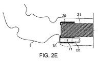
次に図2A〜図2Cを参照して、これらの図面は、本発明のいくつかの代表的な実施形態に従う、吸入口ガード41の壁を含む先端アダプタ20を概略的に示す。
Vacuum Shielding Referring now to FIGS. 2A-2C, these drawings schematically illustrate a
本発明のいくつかの実施形態に関する、図2Cと、図2A〜図2Bはそれぞれ、身体組織によって塞がれる可能性があるおよび/または身体組織に損傷を与える可能性がある排出口95から身体組織を遠ざけるように設計された吸入口ガード41を含む先端アダプタ20の、それぞれ異なる深さにおける側方断面図と端面断面図を示す。
FIGS. 2C and 2A-2B, respectively, for some embodiments of the present invention are shown in FIG. Fig. 4 shows a side cross-sectional view and an end cross-sectional view of the
いくつかの実施形態において、吸入口ガード41は、入口95等の排出口と、上記先端アダプタが体内管腔に挿入されたときの身体の組織との間に配置される。たとえば、吸入口ガード41は、排出口95を通して結腸に吸引力を加えたときに結腸の壁の組織を保護する。いくつかの実施形態において、吸入口ガード41は、先端アダプタ20の周長の少なくとも20%に沿って延在し、先端アダプタ20から遠位方向に延在する。いくつかの実施形態において、吸入口ガード41は、先端アダプタ20の周長の、少なくとも35%、50%、80%もしくは100%に沿って、または、周長のより小さな部分に沿って、または、周長の、これらの中間の部分に沿って延在する。いくつかの実施形態において、吸入口ガード41の最大延在距離は、たとえば3〜5mm、4〜10mm、6〜15mm、10〜20mm、またはこれら以外の、より短いもしくは長い距離である。その周囲に沿った所与のポイントにおける最短延在距離は、いくつかの実施形態において、0mmと、最大延在距離までの任意の距離との間である。いくつかの実施形態において、吸入口ガード41の厚みは、少なくとも0.1〜0.2mm、0.1〜0.3mm、0.2〜0.5mm、0.4〜1.0mm、またはこれら以外のより大きいもしくはより小さい厚みである。いくつかの実施形態において、吸入口ガード41は、少なくとも、通常内視鏡プローブを体内管腔に入れるのに使用される圧力で、その形状を保つよう、剛性または半剛性である。剛性または半剛性の吸入口ガード41は、潜在的に、内視鏡プローブの前進する遠位端の、前方向の挿入を支援する。いくつかの実施形態において、吸入口ガード41は、たとえば管腔壁に向かって直接圧力が加えられたときに潰れるのに十分な可撓性を有する。これは、内視鏡プローブが前進するときの傷を少なくするための潜在的な利点である。いくつかの実施形態において、吸入口ガード41は、たとえば1〜4PSI、3〜8PSI、5〜10PSI、8〜15PSI、またはこれらよりも高いもしくは低い圧力しきい値で潰れるよう、ナビゲーション補助と安全に潰れること双方を含む、可撓性/剛性を備えるように設計される。吸入口ガード41は、本明細書に記載のクリーニングシステムおよび/または先端アダプタのうちのいずれかの任意の特徴である。
In some embodiments, the
吸入口ガード41によって提供される保護は潜在的に、本明細書に記載の機構から選択された1つ以上の機構、および/または別の機構によるものである。いくつかの実施形態において、シールド41は、排出管腔22と流体連通状態にある吸入入口を、排出管腔22の露出した吸入口開口95と比較して、壁との接触が少ない場所および/または向きに配置する。任意で、この位置は、潜在的に体内管腔壁と高圧力勾配領域との間の距離を大きくする、より中間の位置である。任意で、この向きをシフトして壁との接触を起こり難くする。これはたとえば、装置の遠位−近位軸に対して垂直な向き(遠位移動中に壁の突起と接触する傾向があり得る)と遠位−近位軸に平行な向き(壁の平坦領域と接触する傾向があり得る)のおよそ中間である回転である。本発明のいくつかの実施形態において、中間は、いずれの軸からも少なくとも30°離れた角度を含む、または、少なくとも35°、40°、またはこれら以外の中間、より大きいもしくはより小さな分離角度を含む。いくつかの実施形態において、開口は移動も回転もする。たとえば、図2A〜図2Cに示される、吸入口ガード41の突出した壁部分によって定められる吸入入口は、約90°回転して中間方向に向き、中間方向において開口を移動させる。
The protection provided by
本発明のいくつかの実施形態において、吸入口ガード41は、壁の閉塞部分に一致しない可能性が高い形状を取ることによって保護する。たとえば、吸入口ガードのリップ部を、平坦でない開口入口を定めるように形成してもよく(たとえば、吸入口ガードの縁は、1つの面の中に実質的に含まれないリップ部を形成する)、および/または開口入口は、壁部分が開口の上に重なるのを防止する構造によって1つ以上の側面が保護される。たとえば、結腸内視鏡自身の遠位端が、図2Cの吸入口ガード41の開口が、腸壁の大きな範囲によって全体的に閉塞されるのを、防止する。いくつかの実施形態において、吸引入口の領域における干渉が、接触ポイントから10mmを超えて続く、または、5〜10mm、10〜15mm、8〜20mm、または、境界が同一である、中間の、より小さいもしくはより大きい、別の連続範囲を超えて続く、壁の広がりによる、全体的な閉塞を防止する。
In some embodiments of the present invention, the
本発明のいくつかの実施形態において、吸入口ガード41は、より大きな吸引入口面積を形成し、全体的な閉塞の可能性を低くすることによって保護する。たとえば、腸壁の凸凹1Aは大きさが限られているので、十分に大きな開口は、この凹凸の面の方向を向いていても、閉塞されない。本発明のいくつかの実施形態において、吸引入口は、突出範囲が5mm未満の組織の垂下部分による全体的な閉塞を防止するのに十分大きい。いくつかの実施形態において、突出範囲が5〜10mm、2〜5mm、8〜12mm未満の、境界がこれらに等しい、中間の、より大きいもしくはより小さい他の範囲である、突出部分を有する、組織の垂下部による閉塞を防止する。
In some embodiments of the present invention, the
吸入入口の面積を大きくすることの別の潜在的利点は、結腸内圧力に対して差圧が大きい領域が、吸入口の開口自体の近くで露出するのではなく、排出路および/または吸入口ガードの吸入構造の中の深い場所に位置するのを保証するのに役立つ点にある。 Another potential advantage of increasing the area of the inlet is that the area where the differential pressure relative to the pressure in the colon is large is not exposed near the inlet opening itself, but the outlet and / or inlet It helps to ensure that it is located deep within the inhalation structure of the guard.
次に図7A〜図7Cを参照して、これらの図面は、本発明のいくつかの代表的な実施形態に従う、全周吸入口ガード41を含む先端アダプタ19Aの一例を概略的に示す。図7A〜図7Bは異なる断面の正面図を示す。図7Cは水平断面の図を示す。
Reference is now made to FIGS. 7A-7C, which schematically illustrate an example of a
いくつかの実施形態において、吸入口ガード部42は、排出管腔22を保護する領域41Aよりも、先端からの突出距離が短い。全周吸入口ガード41の潜在的な利点は、体内管腔の中に向かって進むための入口ポイントがより狭い点にある。
In some embodiments, the
いくつかの実施形態において、より短い領域42は、撮像装置50までの径方向距離がより短い場所に位置することができ、それにより、吸入口ガード41の延長部によって撮像装置50の視野72が閉塞することを減じるまたは防止する。いくつかの実施形態において、1つ以上の位置決め要素17A、17Bは、遠位内視鏡領域21の端部に対して先端アダプタ19Aが相対的に適切な位置にあることを保証するように作用する。
In some embodiments, the
次に図8A〜図8Cを参照して、これらの図面は、本発明のいくつかの代表的な実施形態に従う、端部が奥に位置する吸入口ガード41Bを含む先端アダプタ19Bの一例を概略的に示す。図8A〜図8Bは異なる断面の正面図を示す。図8Cは水平断面の図を示す。
Referring now to FIGS. 8A-8C, which schematically illustrate an example of a
いくつかの実施形態において、吸入口ガード41Bは、先端アダプタ19Bの遠位端から奥に入った位置にある。この位置の潜在的な利点は、遠位内視鏡領域21の進行および/または視野の妨害が少ない状態で、排出管腔22を保護する点にある。特に、前進する遠位端の最も遠位部分の拡がりは、先端アダプタの固定構造を収容するのに使用される先端アダプタ19Bの厚み分だけである。いくつかの実施形態において、1つ以上の位置決め要素17A、17Bは、遠位内視鏡領域21の端部に対して先端アダプタ19Bが相対的に適切な位置にあることを保証するように作用する。
In some embodiments, the
再び図2A〜図2Cを参照して、先端アダプタ20のチャンバ43は、内視鏡21の遠位端を収容するためのものである。これらの図面におけるチャンバ220は、上記のように任意で近位方向の真空源に接続するチューブ22を収容するおよび/またはチューブ22に接続する(かつ機能的に延長する)ためのものである。近位真空源によって発生した吸引力71は、いくつかの実施形態において、チューブ22およびチャンバ220によって排出口95に送られる。
Referring again to FIGS. 2A to 2C, the
本発明のいくつかの実施形態において、先端アダプタ20は遠位吸入口ガード41を含む。潜在的に、吸入口ガード41は、体内管腔壁組織またはその他の身体組織を、排出口95に潜在的に存在する高レベルの真空を直接受けないように引離す役割を果たす。
In some embodiments of the invention,
次に図2Dおよび図2Eを参照して、これらの図面は、本発明のいくつかの代表的な実施形態に従う、腸壁1の一部分1Aと、先端アダプタ20の排出管腔22を通して方向71に引かれる真空との逢着を示す。図2Dにおいて、内視鏡21の前進する遠位端が、壁1の凹凸1Aに近づいている。図2Eにおいて、凹凸1Aが排出管腔22の開口に向かって引張られている。しかしながら、有効な排出口と軟質の身体組織とのこの接触モードを防止することが潜在的な利点である。このシナリオにおいて潜在的に生じる欠陥は以下の通りである。
Referring now to FIGS. 2D and 2E, these drawings are in
・身体組織が排出口に向かって吸引されその中に入ってこの排出口を塞ぎ、管腔クリーニングプロセスの適切な機能を妨げる。 • Body tissue is aspirated towards and into the outlet, blocking it and preventing proper function of the lumen cleaning process.
・排出口の中に吸引された身体組織に外傷を与える。
排泄物を(たとえば)結腸から効率的に高速で排出するのに十分な強度の吸引力は、潜在的に、強い吸引力を受けた組織の血腫、血管の破れ、またはその他の望ましくない結果をもたらすほどに強い。
・ Treat the body tissue sucked into the outlet.
Sufficient suction force to efficiently drain (for example) excreta from the colon at high speed can potentially cause hematoma, vascular tears, or other undesirable results in tissues that have received strong suction force. Strong enough to bring.
次に図3Aおよび図3Bを参照して、これらの図面は、本発明のいくつかの代表的な実施形態に従う、腸壁1の一部分1Aと、延長部41が設けられた先端アダプタ20の排出管腔22を通して方向71に引かれる真空との逢着を示す。図3Aにおいて、内視鏡21の前進する遠位端が、壁1の凹凸1Aに近づいている。図3Bにおいて、凹凸1Aが、前方に押出されて排出管腔22の開口から遠ざかることで、吸引力71から保護される。
Referring now to FIGS. 3A and 3B, these drawings show the drainage of a
次に図2A〜図2Cを参照して、いくつかの実施形態において、延長部41は、排出口95と、結腸の壁等の傷付き易い組織との間にあり、身体組織による排出口95の閉鎖を防止しつつ、この組織が損傷を受けないよう保護する。いくつかの実施形態において、吸入口ガード41は、排出口95の近くに位置する。任意で、吸入口41は、先端アダプタ20の全体または大部分の周囲に位置し、排出口95に直に近接する位置に限定されない。
Referring now to FIGS. 2A-2C, in some embodiments, the
任意で、吸入口ガード41は、図2Cに示されるように、先端アダプタ20の中心軸に向かって湾曲している。
Optionally, the
次に図6A〜図6Bを参照して、これらの図面は、本発明のいくつかの代表的な実施形態に従う吸入口ガード41を撮像開口50との関連で示す。
Reference is now made to FIGS. 6A-6B, which illustrate an
任意で、吸入口ガード41は、内視鏡10の光学部品の視界72を限定することを避けるまたは部分的に避けるように配置される。
Optionally, the
次に図4A〜図4Bを参照して、これらの図面は、本発明のいくつかの代表的な実施形態に従う、少なくとも1つの開口60を有する吸入口ガード41を含む先端アダプタ20を概略的に示す。
4A-4B, which schematically illustrate a
本発明のいくつかの実施形態において、吸入口ガード41は1つ以上の(任意で小さい)孔60を含み、この孔を通してクリーニングを行なうことができる。この構成は、図4Bの側面断面図と図4Aの正面断面図に示されている。任意で、孔60は、先端アダプタ20が体内管腔の中で前進するときに管腔壁の組織を切るまたは削ることがないよう、丸くされた縁を有していてもよい。
In some embodiments of the present invention, the
孔60の適切なサイズおよび位置は、クリーニング対象の材料の特徴、使用する洗浄の性質、与える吸引力の強度、およびその他さまざまな作業パラメータに応じて異なり得る。図4Aおよび図4Bは、代表的なかつ非限定的な実施形態を示す。いくつかの実施形態において、孔60は、結腸内圧力に対して比較的小さい圧力差の影響を受ける吸引力に晒される内部領域に孔60が重なるように配置される。たとえば、この孔は、吸入ガード41の遠位端近くに配置してもよく、および/または吸入ガード壁41の内側に形成されたチャンバの最も近い部分が比較的大きくなるように、配置してもよい。いくつかの実施形態において、このより大きなチャンバ領域は、効果的に大きくされた「パイプ」直径に対応し、結果として、たとえばベルヌーイの原理に従って、圧力降下が小さくなる。これは、組織の安全性にとって、および/または近づいてくる組織を吸引する傾向を小さくする上で、潜在的な利点である。
The appropriate size and location of the
いくつかの実施形態において、老廃物をできるだけ多く排出することと、結腸部分の組織が受ける圧力勾配をできるだけ小さくすることの間には、潜在的な対立状態が存在する。これに折合いをつける実施形態では、そのため、粒子を除去するのに吸引力に頼らない。また、開口が、これらの開口が受ける圧力差が最小となる排出路につながるようにすることも潜在的な利点である。排出路につながる構造の別の潜在的な利点は、このような開口近くの断面が広く、組織に近くなる領域から奥に入るにつれて狭くなる点にある。 In some embodiments, a potential conflict exists between expelling as much waste as possible and minimizing the pressure gradient experienced by the tissue in the colon portion. In an embodiment that compromises this, it does not rely on suction to remove the particles. It is also a potential advantage that the openings lead to a discharge path that minimizes the pressure differential experienced by these openings. Another potential advantage of the structure leading to the drainage path is that the cross-section near such an opening is wide and narrows from the region closer to the tissue toward the back.
いくつかの任意の使用方法に従うと、医師は、クリーニングが必要な領域の上に孔60が適切に配置されたときにチューブ22の中の吸引力をオンにし、損傷を受け易い組織の上に孔60が配置されたときに吸引力をオフにするかまたは小さくする。
According to some optional usage, the physician turns on the suction force in the
次に図5Aおよび図5Bを参照して、これらの図面は、本発明のいくつかの代表的な実施形態に従う、腸の管腔からの流体および浮遊老廃物30の排出を示す。各図面において、腸壁1に含まれる管腔の老廃物が、延長部41が設けられた先端アダプタ20の排出管腔22を通して真空によって方向71に排出されている。
Referring now to FIGS. 5A and 5B, these drawings illustrate the drainage of fluid and suspended
図5Aにおいて、内視鏡21の遠位端は部分的に流体および浮遊老廃物30の中に沈んでいる。吸引力71は、延長部41を含むバリアがあるので、老廃物の浮遊物30を完全に排出することができない。図5Aにおいて、内視鏡21の遠位端は部分的に流体および浮遊老廃物30の中に沈んでいる。吸引力71は、延長部41に設けられた1つ以上の孔60により、排出された老廃物の懸濁部の残りにアクセスする。
In FIG. 5A, the distal end of
なお、いくつかの実施形態において、先端アダプタ20は、たとえば(図2Aに示される)照明LED105、撮像ポート107、作業通路102、および洗浄路103を含む、結腸内視鏡の先端に位置する結腸内視鏡の構成要素がその中に存在しない状態を保つように構成されている。
It should be noted that in some embodiments, the
代表的な先端アダプタ
次に図11A〜図11D、図13A〜図13C、および図17A〜図17を参照して、これらの図面は、本発明のいくつかの代表的な実施形態に従う、内視鏡10の遠位部分21に搭載することが可能なクリーニングシステム100の先端アダプタ20の構成を概略的に示す。
Exemplary Tip Adapters Referring now to FIGS. 11A-11D, 13A-13C, and 17A-17, these figures illustrate an endoscope according to some exemplary embodiments of the invention. 1 schematically illustrates the configuration of a
いくつかの実施形態において、これらの図面に示され本明細書の他の場所で参照される「先端アダプタ」は、チューブ110に接続可能であり、かつ図1のクリーニングシステム100等のクリーニングシステムの他の部分に接続可能であることが、理解されねばならない。
In some embodiments, a “tip adapter” shown in these drawings and referred to elsewhere herein can be connected to a
また、本明細書で「先端アダプタ20」と一般的に呼んでいるものの構成は、必要に応じて変更されて、本明細書に記載の、個別に説明したすべての先端アダプタ(たとえば先端アダプタ11A〜11C、12、13、および19A〜19B)と、本発明の実施形態として本明細書に示される「先端アダプタ」の説明に従うその他すべての装置を含むことが理解されるはずである。
In addition, the configuration of what is generally called “
図11A〜図11Dは、内視鏡10の遠位端に搭載された先端アダプタ11A〜11C(および20)の側面断面図を概略的に示す。
11A-11D schematically show side cross-sectional views of tip adapters 11A-11C (and 20) mounted at the distal end of
図11A〜図11Cに示される代表的な実施形態において、先端アダプタ11A、11Bは、内視鏡の遠位端に適合するように成形され、任意で周長全体またはその一部に突起16を有する、または、先端アダプタ11A、11Bが内視鏡の遠位端21に固定された位置関係で確実に配置されるようにするためのその他の特徴を有する。
In the exemplary embodiment shown in FIGS. 11A-11C, the
次に図12A〜図12Bを参照して、これらの図面は、本発明のいくつかの代表的な実施形態に従う、内視鏡の遠位端21に関連する先端アダプタ11Bの正面断面図および側面断面図をそれぞれ示す。
Referring now to FIGS. 12A-12B, which are front cross-sectional views and side views of a
突起16の形状を調整して内視鏡の遠位部分21の端部に位置する特徴の機能を収容するようにすることは、潜在的な利点である。いくつかの実施形態において、たとえば、突起16は、撮像装置50の視野72の近くに配置される可能性がある先端アダプタ11Bの部分から後退させてもよい。この後退により、配置機能は、内視鏡の光学部品および/または洗浄、作業通路、および/または照明等のその他の特徴の機能的動作を損なうことなく動作することができる。
It is a potential advantage to adjust the shape of the
図11D、図13A〜図13C、および図17A〜図17Bは、本発明のいくつかの実施形態に従う、内視鏡の遠位部分21に対する配置が可変であるかまたは内視鏡の遠位端21ではなくその近くに固定的に配置される先端アダプタの、単純化した概略図である。
11D, 13A-13C, and 17A-17B are variable in placement relative to the
図13A、図13B、および図13Cはそれぞれ、横方向から内視鏡の遠位部分21の上に嵌めるように構成された(先端アダプタ20である)先端アダプタ12の、正面断面図、正面断面図、および側面断面図である。いくつかの実施形態において、インターフェイス先端アダプタ12は、弾性変形可能であり、圧力による把持によって内視鏡の端部21を把持する大きさにされている(把持圧力方向がたとえば矢印26で示されている)。任意で、先端アダプタ12は、ユーザが、内視鏡の遠位部分21の端部のまたは端部近くの選択可能な位置に嵌める。いくつかの実施形態において、先端アダプタ12は、任意で内視鏡の遠位部21に沿って位置決めするためにスライド可能である。いくつかの実施形態において、先端アダプタ12は、内視鏡の遠位端21を十分な力で把持することにより、結腸またはその他の体内管腔への挿入中に内視鏡21に通常加えられる圧力の影響下でも内視鏡の遠位端21上で移動しない。
13A, 13B, and 13C are a front cross-sectional view and a front cross-sectional view, respectively, of the tip adapter 12 (which is the tip adapter 20) configured to fit over the
次に図15Aおよび図15Bを参照して、これらの図面は、本発明のいくつかの代表的な実施形態に従い、弾性変形可能な先端アダプタ12B、12Cの、周方向の異なる延在範囲を概略的に示す。
Referring now to FIGS. 15A and 15B, which schematically illustrate different circumferential extents of the elastically
いくつかの実施形態において、先端アダプタ12B、12Cの周方向の範囲は、先端アダプタが装着された内視鏡の遠位部分21の後方から把持できるようにするのに十分な角度である。いくつかの実施形態において、この角度はまた、アダプタが、側方から内視鏡部分21を通すのに十分大きく開くように、選択される。
In some embodiments, the circumferential extent of the
いくつかの実施形態において、たとえば、先端アダプタ12B(図15A)は、内視鏡の周長の約2/3にわたって延在している。周方向の券回範囲は、装着点における内視鏡の直径に応じて可変であることが理解されるはずである。
In some embodiments, for example,
いくつかの実施形態において、たとえば、先端アダプタ12C(図15B)は、装着点において内視鏡の周長の180°を少し超える範囲のみに延在している。いくつかの実施形態において、装着の安全性は、先端アダプタ12Cの可撓性を小さくし、下にある内視鏡に対する圧力が強くなるようにすることによって、高くなる。 In some embodiments, for example, the tip adapter 12C (FIG. 15B) extends only to a range slightly over 180 ° of the circumference of the endoscope at the attachment point. In some embodiments, mounting safety is increased by reducing the flexibility of the tip adapter 12C and increasing the pressure on the underlying endoscope.
このように、いくつかの実施形態において、自身の弾性復元力によって自動装着する先端アダプタを、弛緩状態開口部とともに構成してもよい。この開口部のサイズは、内視鏡直径の0%(スリット状)から、把持できるようにするのに十分に小さい値までの、いずれかである。弛緩状態開口のサイズはしたがって、内視鏡直径の20%〜80%、またはこれよりも大きいもしくは小さいサイズである。いくつかの実施形態において、アダプタは、内視鏡プローブの輪郭の周囲約50%からより大きな値の範囲にわたって嵌められる。より完全に包囲するアダプタは潜在的に強固な把持をもたらすが、その代わりに内視鏡プローブの直径が大幅に大きくなる。 Thus, in some embodiments, a tip adapter that automatically attaches with its own elastic restoring force may be configured with a relaxed state opening. The size of the opening is any value from 0% (slit shape) of the endoscope diameter to a value small enough to enable grasping. The size of the relaxed opening is therefore 20% to 80% of the endoscope diameter, or larger or smaller. In some embodiments, the adapter is fitted over a range of values from about 50% around the contour of the endoscope probe to greater values. More fully enclosing adapters provide a potentially firm grip, but instead the diameter of the endoscopic probe is significantly increased.
先端アダプタ(アダプタ12B、12C、または本明細書に記載のその他いずれかの先端アダプタ)の本体の材料は、シリコーンゴムまたはその他のポリマー材料、たとえば、そうでなければ結腸内視鏡または結腸クリーニングシステム挿入チューブの製造に使用されるポリマー樹脂とすることができる。先端アダプタの材料の代表的なショアAデュロメータ値は、50〜70ショアAデュロメータ単位である。いくつかの実施形態において、デュロメータ範囲として、50〜55ショアA、50〜60ショアA、55〜65ショアA、70〜80ショアA、70〜90ショアA、または、境界がこれらに等しい、中間の、より高いもしくはより低い、デュロメータのその他の範囲が使用される。
The material of the body of the tip adapter (
いくつかの実施形態において、透明材料を用いて先端アダプタ(たとえば先端アダプタ12B、12Cまたは本明細書に記載のその他いずれかの先端アダプタ)を形成する。透明であることの潜在的な利点は、結腸内視鏡の端部に対するアダプタの位置決めがより直接的に判断される点にある。
In some embodiments, a transparent material is used to form a tip adapter (eg,
次に図16A〜図16Cを参照して、これらの図面は、本発明のいくつかの代表的な実施形態に従う、内視鏡の遠位部分21に対する弾性変形可能な先端アダプタ12の3つの構成を示す。
Referring now to FIGS. 16A-16C, which illustrate three configurations of an elastically
示されている構成は、装着前(図16A)、装着途中(図16B)、および装着後(図16C)である。この流れは、内視鏡の側方からアダプタ12を嵌めるときの可撓性を示しており、内視鏡のチューブ上に押し込まれると形状が復元されて装着が可能になることを示している。
The configuration shown is before mounting (FIG. 16A), during mounting (FIG. 16B), and after mounting (FIG. 16C). This flow shows the flexibility when the
いくつかの実施形態において、内視鏡の遠位端21に対する先端アダプタ20の位置は、ユーザが、好みに応じておよび/または所与の臨床状況に応じて選択し、先端アダプタ20は選択された位置に従って内視鏡の遠位端21に装着される。いくつかの実施形態において、先端アダプタ20および/または装着されたチューブ110は、一度限りの使用が意図された使い捨て可能な物である。
In some embodiments, the position of the
いくつかの実施形態において、遠位インターフェイス20は、端部自身から近位方向に距離を置いた位置で内視鏡の遠位領域21に固定接続される(図13C)。この距離は、内視鏡の遠位端から、少なくとも、たとえば0.5〜1.5cm、1〜2.5cm、2〜5cm、または、これらよりも短いもしくは長い距離である。
In some embodiments, the
図13A〜図13Cおよび図17A〜図17Bに示される構成の潜在的な利点は、内視鏡10の光学部品の全視野が保証される点である。先端アダプタ20が、内視鏡の端部21近くに位置するもののこの端部から幾分離れている場合は、先端アダプタが異常に大きくても、内視鏡の光学部品の全視野を妨害することはないであろう。
A potential advantage of the configuration shown in FIGS. 13A-13C and 17A-17B is that the full field of view of the optical components of the
いくつかの実施形態におけるいくつかの使用方法において、クリーニングシステム100が装着された内視鏡10を、結腸の長さ全体にわたって前進させることができ、その前進中にクリーニングシステムを使用することにより、クリーニングシステムは、結腸の長さにわたる部分から排泄物を取除く。その後、任意で、検査および/または治療のために、クリーニングされた結腸を通して内視鏡を徐々に後退させる。この方法において、先端アダプタ20が内視鏡の遠位端の近傍に位置していることは、前進/クリーニング中においても、後退/観察中においても、都合が良い。前進中、潜在的に、遠位先端部は、より簡単に狭い空間に貫入することができる。貫入のポイントでアダプタの先端に加わる体積を支持する必要がないからである。後退中、潜在的に、アダプタ先端は照明および/または撮像素子に干渉しない。これらの照明範囲および/または視野から物理的に外れているからである。
In some methods of use in some embodiments, the
図17Aおよび図17Bは、内視鏡21上に、任意で内視鏡の側方から搭載され、内視鏡の周長の一部(たとえば約40%または約50%または約60%または約70%または約80%)に沿って、内視鏡21の遠位部分と接触しているまたはその近傍にある、先端アダプタ13を例示する(正面図および側面図)。いくつかの実施形態において、これは周長の50%を囲んでいない。いくつかの実施形態において、インターフェイス先端アダプタ13は、内視鏡21の遠位部分に沿うさまざまな位置で装着可能である。任意で、先端アダプタ13は、接着テープ、クランプ、および/またはそれ以外の機械的手段、接着手段、および/または粘着手段、ストラップ等の留め具14によって、および/または接続チューブ110に沿って留め具112によって、適所で保持される。これら自身も、図1を参照して先に述べたように内視鏡10の長さに沿って先端アダプタ13に接続されている。
17A and 17B are optionally mounted on the
いくつかの実施形態において、インターフェイス先端アダプタ12および13は、医師の都合に合うように、および/または特定のケースの臨床要件に合うように、内視鏡21の遠位部分上のいずれかの場所に配置することができる。先端アダプタ13が可撓性を有しおよび/または側方から装着可能であることの潜在的な利点は、さまざまな形状および/または直径の内視鏡とともに使用するために先端アダプタ13を内視鏡に装着できる点にある。いくつかの実施形態において、先端アダプタ13を、弾性可撓性を有する材料で構成することにより、大きさが変化する内視鏡にさらに適応できるようにする。同様の理由で、先端アダプタ13は、任意で、非円形または非対称の断面を有する遠位内視鏡21の一部への搭載に適応可能である。
In some embodiments, the
図11D、図13A〜図13C、および図17A〜図17Bに示される実施形態は、任意で、「クリーニングチューブ」(すなわち1本以上の洗浄チューブおよび/または1本以上の排出チューブ)の遠位出口を、内視鏡の遠位端に対してユーザが選択した位置に配置するために使用できる。 The embodiments shown in FIGS. 11D, 13A-13C, and 17A-17B are optionally distal to a “cleaning tube” (ie, one or more wash tubes and / or one or more drain tubes). The outlet can be used to position the user at a location selected by the distal end of the endoscope.
次に図10A〜図10Dを参照して、これらの図面は、本発明のいくつかの代表的な実施形態に従う、内視鏡遠位端21に対する、先端アダプタ20の、端部を超えた装着を示す。
Referring now to FIGS. 10A-10D, which illustrate the attachment of the
いくつかの実施形態において、先端アダプタ20は、遠位端に対するある位置範囲に、内視鏡遠位領域21の端部を超えて、装着することができる(図10B)。この位置は、端部と同一面にあってもその近くでもよい(図10C)、または、距離28たとえば0.5〜1.5cm、1〜2cm、1.5〜3cm、またはこれら以外のより長いもしくはより短いオフセット長さだけ、近位方向にオフセットされていてもよい。
In some embodiments, the
次に図9A〜図9Dを参照して、これらの図面は、本発明のいくつかの代表的な実施形態に従う、直径が可変の内視鏡遠位端21に先端アダプタ20を装着することに関連する問題を示す。
Referring now to FIGS. 9A-9D, these drawings illustrate attaching the
いくつかの実施形態において、内視鏡遠位部分21は、内視鏡遠位端から近位方向にわたって比較的一様の直径36を有する(図9A〜図9B)。本発明のいくつかの実施形態において、内視鏡の遠位部分は、ここで示すように直径が一様ではなく、たとえば、内視鏡が操縦機構および/またはその他の構造体を包んでいるために、直径が不規則である場合がある。図1の内視鏡遠位部分21の断面の外観はこの不規則性を反映している。なお、弾性変形可能な実施形態、たとえば図13A〜図13Cの実施形態の潜在的な利点は、潜在的にこれらがこのような不規則性に自動的に適応する点にある。
In some embodiments, the endoscope
いくつかの実施形態において、この不規則性は、先端アダプタ20を遠位端の上に嵌めるときの障害になるのに十分大きい。たとえば、拡大領域27(図9C〜図9D)の直径35は、直径36よりも大きいので、内視鏡遠位領域21の遠位端近傍において、端部を超えてぴったりと装着するときの障害になる。
In some embodiments, this irregularity is large enough to be an obstacle when fitting the
次に図14A〜図14Cを参照して、これらの図面は、本発明のいくつかの代表的な実施形態に従う、拡大遠位部分27を含む内視鏡プローブに対する先端アダプタ12の装着を示す。
Referring now to FIGS. 14A-14C, these drawings show the attachment of the
いくつかの実施形態において、内視鏡遠位領域21は、拡大部分27とともに、たとえば遠位端を囲むリング137とともに構成される。リング137またはその他の拡大部分27を設けて、内視鏡21の機能上の必要性を満たしてもよい、たとえば、操縦ツール、照明、および/または撮像光学部品を収容してもよい。それでもなお、このような拡大部は潜在的に、内視鏡端部のナビゲート性を妨げる。元の内視鏡の設計では操縦性を保つために十分な注意がなされてきたであろうが、内視鏡の遠位端をさらに拡大する先端アダプタ20を加えることは、潜在的に、結腸を通して上手くナビゲートすることの障害になる。
In some embodiments, the endoscope
拡大遠位部の近くの位置で内視鏡21に装着可能な12または13等の先端アダプタは、潜在的に、先端アダプタと内視鏡を組合わせたものの輪郭形状をより細くすることができる。潜在的に、輪郭が細いほどナビゲートし易い。たとえば図14A〜図14Cにおいて、示されている先端アダプタ12は、拡大部27の近くの領域に装着され、内視鏡の遠位端21の拡大部27の上に直接配置された場合のアダプタの輪郭12A以内の輪郭にすることができる。
A tip adapter such as 12 or 13 that can be attached to the
次に図15Cを参照して、図15Cは、本発明のいくつかの代表的な実施形態に従う、遠位端拡大部27の上にある、先端アダプタ12Dの収容エリア220の延長部分220Aを示す。
Referring now to FIG. 15C, FIG. 15C shows an
いくつかの実施形態において、先端アダプタ12Dは、内視鏡遠位領域21の端部に遠位方向に装着されるように構成され、その短い延長部220Aが拡大領域27の上に乗り前方に突出することにより、排出路95の開口を、たとえば、より前方にしつつ、先端アダプタ12の本体は、より隠れた近位場所に留めている。
In some embodiments, the
次に図11Dを参照して、図11Dは、本発明のいくつかの代表的な実施形態に従う、内視鏡遠位部分21と関連付けられた、端部を超えて装着される先端アダプタ11Cを示す。
Referring now to FIG. 11D, FIG. 11D shows a tip adapter 11C attached beyond the end associated with the distal
側面装着先端アダプタの潜在的な利点は、図11Dを図14Cと比較すればわかる。図11Dにおいて、アダプタ11Cは、遠位拡大部27の上をスライドした後、内視鏡21の遠位端から距離を置いた場所に位置する。しかしながら、結果として得られた構成は十分に嵌合しておらず、図14Cの構成で得られる直径と比較すると過剰な直径になっている。図11Cのように、遠位端により強固に搭載された、端部を超えて装着される構成の場合であっても、先端アダプタ11Bは潜在的に、図14Cの構成よりも障害になり易い。
The potential advantages of the side mounted tip adapter can be seen by comparing FIG. 11D with FIG. 14C. In FIG. 11D, the
次に図18A〜図18Cを参照して、これらの図面は、本発明のいくつかの代表的な実施形態に従う、硬質外殻1801と軟質挿入部1805とを備える先端アダプタ1800を概略的に示す。また、図19A〜図19Cを参照して、これらの図面は、本発明のいくつかの代表的な実施形態に従う、排出前室1910を含む先端アダプタ1900を概略的に示す。
Reference is now made to FIGS. 18A-18C, which schematically illustrate a
本発明のいくつかの実施形態において、先端アダプタ1800、1900は、結腸内視鏡の遠位端を受けるように大きさが定められ成形された結腸内視鏡搭載管腔1903を含む。任意で、先端アダプタ1800、1900はまた、
・排出路のチューブ用の1つ以上の排出路搭載ソケット1902、
・洗浄流体を与えるチューブ用の1つ以上の洗浄路搭載ソケット1912、および/または、
・圧力検知手段を受けるための1つ以上の圧力センサソケット1918、1914を備える。
In some embodiments of the present invention,
One or more discharge
One or more wash path mounted
It comprises one or more
本発明のいくつかの実施形態において、排出ソケット1902は、結腸クリーニング装置先端アダプタの、組立て、検知、安全性、および/または排出路の閉塞抵抗に関連する構造を含む。
In some embodiments of the present invention,
いくつかの実施形態において、排出路22のチューブの遠位端は、排出路搭載ソケット1902の近位側に挿入される。任意で、これは、摩擦嵌めおよび/または接着剤によって固定される。任意で、チューブの挿入深さはチューブストップ1904によって制限され、これは、排出ソケット1902の管腔の中の部分制限を含む。この部分制限は、任意で、ソケット1902の周方向に狭くなっている部分である。任意で、上記ストップは、管腔壁の非円周形状に盛り上がった部分を含む。
In some embodiments, the distal end of the tube of the
いくつかの実施形態において、チューブストップの遠位方向に、排出路先端圧力検知開口1909が設けられる。任意で、圧力検知開口は、排出路搭載ソケット1902と圧力センサソケット1918との間に延在する管腔を含む。いくつかの実施形態において、孔1907が、排出ソケット1902の壁の検知開口孔1909の反対側に設けられる。孔1907は、任意で、製造プロセス中に作成されて孔1909の作成のためのアクセスを提供する。加えてまたは代わりに、これは、二次吸引軽減開口の役割を果たす。
In some embodiments, a drain tip
いくつかの実施形態において、ソケット1902は、排出前室1910の中に続く遠位排出ソケット開口1923で終端をなす。このため、ソケット開口1923も、排出路の吸入口開口95を含む。
In some embodiments, the
任意で、排出前室1910の近位壁1927は、1つ以上のこのような遠位排出ソケット開口1923を含む。いくつかの実施形態において、排出前室1910の遠位壁1925は、1つ以上の排出前室アクセス開口1921を含む。任意で、排出前室1910は、別の開口1910Aを含み、これを通して管腔1903は前室1910と流体連通する。
Optionally, the
いくつかの実施形態において、前室1910およびその開口を形成する構造は、たとえば図3A〜図5Bおよび/または図7A〜図7Cに関連して説明した機能を有する。たとえば、遠位壁1925は、ソケット開口1923から腸壁1を遠ざける限りにおいて、吸入口ガード41を含む。排出前室アクセス開口1921は、十分小さい材料を通すことができる開口または孔60の実施形態を含む。
In some embodiments, the structure forming the
前室1910およびその開口の構造の潜在的な利点は、サイズが異なる粒状化された老廃物が前室1910を通過し排出吸入口開口1923のうちの1つの中に入るときに受ける圧力から考えることができる。クリーニングプローブの排出路側が下向きにされた状態(たとえば図5A〜図5Bに示される)で、流体レベルは容易に低深度に下がる。なぜなら、アクセス開口1921が先端ヘッド部の低い位置にあり、アクセス開口1921を通した排出路22からの吸引力により十分な圧力勾配が発生して流体体積を動かすからである。
A potential advantage of the structure of the
任意で、アクセス開口1921の大きさは、吸入口開口1923の大きさ以下にされる。任意で、アクセス開口1921は、吸入口開口1923に対して軸方向遠位方向に配置される。これの潜在的な利点は、アクセス開口1921に入った扁平な老廃物粒子が、確実に、排出路を塞がずに排出路の中に入るように方向付けるのに役立つ点にある。この意味において、アクセス開口1921は潜在的に、老廃物粒子ストレーナとして作用する。老廃物粒子が大きすぎる場合および/または不適切な向きに進んでアクセス開口1921に入った場合、それでもなお、老廃物粒子は、アクセス開口1921の中に吸引力によって詰込まれる可能性は低い。なぜなら、他の前室開口1921、1910A、1907のうちの1つによって圧力勾配が緩和されるからである。開口1910Aは比較的高い位置にされ、管腔1903内で比較的保護される位置にあり、予め歪みを加えることが利点になる大きな粒子に逢着する可能性は低い。しかしながら、任意で、開口1910Aを2つ以上のより小さな開口に分割し、潜在的に、吸入口開口1923に対して歪みを加える機能も提供する。
Optionally, the size of the
次に図23を参照して、図23は、本発明のいくつかの代表的な実施形態に従う、遠位先端アダプタ2300に入る粒子2305を示す。
Reference is now made to FIG. 23, which shows a particle 2305 entering the
いくつかの実施形態において、先端2300(排出前室1910に関連する側面を強調するために単純化している)が、管腔1903内の結腸内視鏡プローブ21および排出ソケット1902の排出路22に装着される。前室1910に入った老廃物が排出されるよう、吸引力が能動的に排出路22に加えられる。いくつかの実施形態において、これにより、開口1910Aおよび1921それぞれから追加の吸引勾配2301、2302が生じる。老廃物(固体が懸濁した流体)レベル2223は開口1921またはその上方にあり、老廃物は前室の中に引込まれる。しかしながら、この開口における抵抗が増加すると、それに対応する圧力勾配の急峻さの増加が、開口1910Aの吸引力緩和作用によって減じられる。抵抗は、たとえば腸壁1の一部に当たると、たとえば図2D〜図2Eに関連して示されるように、上昇し得る。潜在的に、圧力勾配の分路は、吸引に関連する傷の発生を減じる作用がある。粒子2305は老廃物粒子を表わしており、これは、一次元寸法が大きいが、開口1921を通ることによって直線状にされているので、吸入口開口1923で詰まらずに通路22に入ることができる。
In some embodiments, a tip 2300 (simplified to emphasize aspects associated with the pre-exhaust chamber 1910) is located in the
いくつかの実施形態において、複数の開口が設けられていることにより、さらに他の機能的利点が得られる。たとえば1つのアクセス開口1921が閉鎖された場合で、も、複数の排出吸入口開口が引続き、別のアクセス開口1921から与えられた、共通の前室1910からの流体を受けることができる。
In some embodiments, the provision of a plurality of openings provides yet another functional advantage. For example, even when one
排出前室1910に関連するその他の機能的側面は、遠位壁1925の曲線形状が、腸壁1からの急峻な圧力を受ける領域を分離する一方で、鈍角前面1802を示すことである。潜在的に、こうすれば、突かれたとき、切断、引っ掛りおよび/またはスライスによる、機械的な損傷が減じられる。曲線状の先端形状が先細りの形状でもある限りにおいて、引っ掛る確率は潜在的に低くなる。なぜなら、先端の形状は、壁の障害物を押すのではなく、滑ってそれを超えることを促す形状であるからである。潜在的に、前面の全体が曲線形状(「球面」形状であるが、実際球面の一部である必要はない)であることによって、腸壁1の形状が同時に適合(および閉鎖)するのに十分適さない入口開口形状を示すので、壁の上に引っ掛る可能性も低下する。
Another functional aspect associated with the
遠位先端部1800、1900の別の側面は、結腸内視鏡搭載管腔1903に関連する構造に関する。いくつかの実施形態において、結腸内視鏡止め1906が設けられ、これは、内視鏡遠位端上に対するクリーニング先端部1800、1900の配置が、結腸内視鏡が停止面1906Aに接触するポイントに正確に制限されるように、管腔1903の中に突出している。たとえば、結腸内視鏡の端部が前室開口1910Aを塞ぐのを防止することは潜在的な利点である。
Another aspect of the
次に図21を参照して、図21は、本発明のいくつかの代表的な実施形態に従う、スリーブ配置ジグ2100の中のスリーブアセンブリ2104を、洗浄システムおよび結腸内視鏡21の構成部品とともに、概略的に示す。
Referring now to FIG. 21, FIG. 21 illustrates a
本発明のいくつかの実施形態において、先端部1800、1900は、完全に組立てられたクリーニング装置を含む結腸内視鏡および/またはその他のチューブ要素をぴったりと収容するおよび/または整形するように大きさが定められたポリマー(ポリウレタン、シリコーンゴム、または別の可撓性ポリマー)の壁が薄い可撓性のスリーブの一端に装着されている。スリーブアセンブリ2104の潜在的な利点は、クリーニング装置を結腸内視鏡に対して可逆装着できること(たとえば、そうすることによってクリーニング装置を使用後に交換および/または廃棄することができる)、クリーニングシステムを結腸内視鏡プローブに一体化させ易いこと、および/または一体化されたクリーニングシステム/結腸内視鏡プローブシステム構成の形状と相対配置を再現できるよう制御されること、である。
In some embodiments of the invention, the
いくつかの実施形態において、スリーブアセンブリは、結腸内視鏡プローブ21を受けるようにされた内側スリーブ2103を含む。内側スリーブ2103は、1つ以上の追加チューブ21、101を含めて、周方向が外側スリーブ2102によって囲まれている。
In some embodiments, the sleeve assembly includes an
いくつかの実施形態において、内側スリーブ2103の管腔の直径は、拡張されていない状態で、たとえば8〜12mm、3〜10mm、5〜18mmの範囲、または、境界が同一、中間、より大きいおよび/またはより小さい他の範囲である。任意で、この直径は、結腸内視鏡の直径に従って選択され、たとえば、(伸張前において)結腸内視鏡の直径よりも、5%、10%、20%、または、これらの中間の、より大きいもしくはより小さい割合、小さい。具体例として、直径12mmの結腸内視鏡の場合、内径は、拡張されていない状態において、結腸内視鏡の直径よりも、0.1〜5mm、1〜3mm、0.1〜0.9mm、または、境界が同一の、中間の、より大きい、および/またはより小さい別のサイズの範囲だけ、小さい。
In some embodiments, the lumen diameter of the
いくつかの実施形態において、スリーブアセンブリ2104は、膨張ジグ2100の膨張ベース2107への装着によって結腸内視鏡プローブを受けるために、膨張可能である。ベース2107は、膨張のために気体圧力源に装着されるように構成された膨張入口2105を含む。任意で、膨張ジグ2100は制限チューブまたは部分チューブ2101を含み、このチューブを通してスリーブアセンブリ2104が延在して内視鏡プローブ21を受ける。内視鏡プローブ21は任意で封止部材2106を通して挿入され、遠位先端部1900の管腔1903に達するまで内側スリーブ2103を通して与えられる。
In some embodiments, the
任意で、可撓性スリーブは、装着チャネル1905Aの円周部によって固定される。任意で、スリーブは、外側チューブと、少なくとも1つの内側チューブとを含み、任意で、内側チューブは装着チャネル1905Aに装着される。任意で、接着導入開口1905が設けられ、先端部の外側から管腔1903および装着チャネル1905に至る。任意で、整形チューブが、一端を管腔1903の中に配置しチャネル1905Aに対して押した後に管腔の周囲全体に接着剤を注入することによって、チャネル1905Aに固定される。図18A〜図19Cに戻って、本発明のいくつかの実施形態において、洗浄路101は、洗浄チューブ受けソケット1912への挿入により、先端部1800、1900で終端を成す。任意で、ソケット1912を細長くして、2つ以上の別個の洗浄チューブを互いに沿って挿入できるようにしてもよい。任意で、ソケットへの挿入深さは、1つ以上の洗浄チューブ止め1903によって設定される。いくつかの実施形態において、ソケット1912ごとに1つ以上の洗浄出口1920が設けられる。任意で、洗浄出口1920は、先端部本体の遠位−近位軸に沿って方向付けられた円筒形の孔を含む。任意で、洗浄出口1920は、そうでなければ、たとえば先細り形状の管腔を含み噴射用に成形されおよび/または方向付けられる、および/または分散のために遠位−近位軸から外れる方向に向けられる、および/または洗浄流体噴霧用にされる。
Optionally, the flexible sleeve is secured by the circumference of the mounting
本発明のいくつかの実施形態において、センサソケット1918、1914は、検知プローブおよび/または検知プローブの一部を受けて、先端の1つ以上の側面および/または先端環境を検知できるように、構成される。たとえば、排出管腔圧力センサソケット1908に、任意で、検知開口1909を通して1つ以上の排出ソケット1902に連結されてその中の圧力および/または圧力変化を検知するセンサが、設けられる。いくつかの実施形態において、電子圧力センサが設けられる。いくつかの実施形態において、機械圧力センサが設けられる。たとえば、圧力センサは任意で、テスト圧力が近位部分に加えられる流体充填チューブを含む。遠位先端部の圧力が上昇および/または低下すると、テスト圧力によって動かされる体積が変化し、これが任意で遠位先端部圧力の測定値および/または表示に変換される。
In some embodiments of the present invention, the
いくつかの実施形態において、外部圧力センサソケット1914が、外部圧力センサ開口1916を通して外部圧力を検知する圧力センサを収容するように構成される。圧力検知ソケット1918に関して述べたように、任意で、ストップ1915の補助により、センサ、たとえば圧力センサの適切な配置を保証する。
In some embodiments, the external
本発明のいくつかの実施形態において、先端アセンブリ1800は、比較的硬質の外殻1801を、より軟質の装着部分1805とともに含む。任意で、装着部分1805は、硬質外殻1801の収容開口1801Aへの挿入部を含む。潜在的に、軟質挿入部/硬質外殻の構成は、各部分1801、1905が果たす機能に応じて材料を選択できることによる利点を提供する。たとえば、硬質外殻は潜在的に、先端アダプタ全体に対してより高い寸法安定性をもたらす。潜在的に、これは、先端部を、遭遇した腸組織に変形して埋め込まれるのではなくその上をスライドするよう促す。これはたとえばナビゲーションおよび/または安定性に関する利点である。潜在的に、軟質挿入部分は、挿入されたチューブが、クリーニングアセンブリに対する曲げ力を受けて適所からずれることに抵抗するための利点をもたらす(チューブ110と同様の軟質性を有するように作られている場合、挿入部分は、チューブが撓むとチューブそのものとともにより大きく曲がる)。
In some embodiments of the invention,
二種類の硬さを有する構造の別の潜在的な利点は、先端部に接続するさまざまな小さなチューブの弾性摩擦嵌合性を、たとえば、ソケット1912、1914、1902、および/または1918を、そこに押し嵌めされるチューブよりもわずかに小さくすることによって、高めることにある。潜在的に、硬質外殻は、腸壁1と接触し易い先端部の領域に比較的低摩擦の材料(本体自身、および/またはコーティング)を使用できるという利点をもたらす。任意で、どちらの構成部品も(硬度が適切に異なる)ポリウレタンで作成する。任意で、外側の構成部品を、たとえば、パリレンC、テフロン(登録商標)、またはその他の低摩擦材料等の摩擦低減材料でコーティングする。
Another potential advantage of a structure with two different stiffnesses is the elastic friction fit of various small tubes connected to the tip, eg,
いくつかの実施形態において、内部先端部分1805の硬度は、たとえば、25〜40ショアA、30〜50ショアA,35〜55ショアAの範囲内、または、境界が同一、より大きい、より小さい、および/または中間である他の軟質性の範囲内である。いくつかの実施形態において、外部先端部分1801の硬度は、たとえば、40〜60ショアA、60〜80ショアA、70〜90ショアAの範囲内、または、境界が同一、より大きい、より小さい、および/または中間である他の軟質性の範囲内である。
In some embodiments, the hardness of the
次に図20を参照して、図20は、本発明のいくつかの代表的な実施形態に従う、可撓性の壁ガード2001を含む先端アダプタ200を概略的に示す。
Referring now to FIG. 20, FIG. 20 schematically illustrates a tip adapter 200 that includes a
本発明のいくつかの実施形態において、先端アダプタ2000は、結腸クリーニング作業中に、間隔開け、位置決め、および/または方向付けを補助するよう機能する、可撓性の壁ガード2001を含む。
In some embodiments of the present invention,
いくつかの実施形態において、壁ガード2001は1つ以上の可撓性部材2002を含む。可撓性部材2002は、一端において先端部本体に装着され、長さ2002Aが、たとえば、約10〜15mm、12〜18mm、15〜20mm、18〜24mm、または、境界が同一、より大きい、より小さい、および/または中間である他の範囲である。いくつかの実施形態において、壁ガード2001の全幅2002Bは、たとえば、約5〜7mm、6〜9mm、8〜12mm、9〜14mmの範囲内、または、境界がこれと同一、より大きい、より小さい、および/または中間である、他の範囲内である。任意で、複数の可撓性部材は、隙間2004によって、たとえば1〜2mmの隙間または別の隙間の幅だけ、分離されている。
In some embodiments, the
いくつかの実施形態において、壁ガード2001の部材は、約180°以上の範囲にわたって十分に曲がるのに十分な可撓性を有する。いくつかの実施形態において、最大の曲げ範囲は、たとえば、約150°、160°、170°、180°、190°、または、その他の、より大きい、より小さい、もしくは中間の最大範囲である。いくつかの実施形態において、加えてまたは代わりに、壁はその長さに沿って、たとえば撓み範囲2008にわたって撓むように構成される。いくつかの実施形態において、最大撓み範囲は、任意で、約2倍(180℃)、またはより小さい範囲、たとえば、約90°、約45°、または、より大きい、より小さい、もしくはより小さい他の最大範囲である。一対の矩形の「ラビットイヤー」構成が図20に示されているが、その他の形状、たとえば、三角形、楕円形、半円形、またはそれ以外の形状も、本発明の実施形態であることが理解されねばならない。本発明のいくつかの実施形態において、壁ガード部材の厚みは、所望の特定の曲げ特性に従い、長さに沿った事実上の曲げを促進するために、先端からの距離に応じて変化している。(たとえばポリウレタンまたは別のゴムポリマーを含む)壁ガード部材2002の硬度は、たとえば、約20〜30ショアA、30〜45ショアA、40〜55ショアA、または、境界が同一、より大きい、より小さい、および/または中間である、他の硬度範囲内である。壁ガード2001は、任意で、本明細書に記載のクリーニングシステムの先端部の実施形態のうちのいずれかを備えることが、理解されねばならない。
In some embodiments, the members of the
次に図22を参照して、図22は、腸壁1および可撓性壁ガード2001と関連して、クリーニングシステム遠位領域2200(たとえば先端アダプタ2100を含む)の、位置2201、2203、2205、2207、2209、2211、2213を示す。トする、腸壁からの、ソフトな(外傷を生じさせない)隔離部として機能することによって、潜在的な利点を提供する。
Referring now to FIG. 22, FIG. 22 relates to the intestinal wall 1 and the
壁ガード2001は、クリーニングシステムの先端部2000がこれを通してナビゲートする、腸壁からの、ソフトな(外傷を生じさせない)隔離部として機能することによって、潜在的な利点を提供する。
それでもなお、壁ガード2001は、任意で、十分に軟質であることにより、十分な力が加わると、たとえば、結腸内に制限(結腸の一部の境界の狭窄)が生じると、潰れて、この制限を通したナビゲーションが損なわれないようにする傾向を有する。位置2200および2213は、それぞれ、遠位方向の向きおよび近位方向の向きに潰れた壁の例を示す。いくつかの実施形態において、部材2002は、圧力源(洗浄チューブ101または壁膨張のために特定的に設けられた別のチューブ)との流体連通を通して膨張可能なバルーンとして設けられる。このことは、任意で、現在のナビゲーション要件に従う壁のスチフネスを制御できるようにする。
Nonetheless, the
本発明のいくつかの実施形態において、壁ガード2001は、結腸内で先端部を径方向に位置決めするのを助ける装置の役割を果たす。たとえば、先端部が位置2207から前進すると、壁ガード部材2202は、後方に撓み、かつライン2006Aの位置を近似する位置および/または位置2213まで撓んで、先端部が腸壁1により近付くことができるようにする傾向がある。しかしながら、わずかに後方に引張られて、部材2002は、たとえば位置2008Aおよび/または2207に向かって直線状になる傾向がある。これは潜在的に先端部を壁から離れるように押す。任意の代替の操作は、先端部を近位方向に引くことによって壁を前方に曲げ、この位置から、前進し壁を上昇するようにすることである(たとえば一連の位置2201、2203、2205、2207)。これにより、先端部について異なる径方向位置を選択することができ、そうすれば、潜在的に、洗浄流体を供給したときにどの位置に向けて噴射するかを選択できるようになり、たとえば、噴射方向2230と2231との間には位置の違いがある。加えてまたは代わりに、先端部を、壁ガードによって、さらに前進するのにより適した位置、たとえば腸制限部の開口領域により近くなるよう、再度位置決めする。任意で、先端領域の短い後方移動と前方移動を交互に行なう(たとえば位置2201と2213との間)ことにより、先端部が管腔内で腸壁1に向かっておよび腸壁1から遠ざかるように(たとえば2200のような経路に平行)「スキャン」を行なう。これは、潜在的に、洗浄噴射エネルギをクリーニング対象2222に対して分配する、および/または老廃物レベル2223に対して腸から流体を排出するのに適した位置を選択できる(たとえば、排出吸入口ゾーンをレベル2232と2233の間に位置決めすることができる)。排出位置は、任意で、たとえば、排出アクセス開口1921が浸漬されるが排出前室開口1910Aは流体がない状態を保つように、選択される。任意で、装置の回転により、壁部材2002のうちの一方に対して他方よりも大きな力が生じる。これは別のガード壁介在方法である。任意で、装置を意図的に約90°回転させることにより、ガード壁をずらし排出アクセス開口の一部を下にある腸壁1の部分により近くなるようにして、残っている少量の流体を排出できるようにする。
In some embodiments of the present invention, the
本明細書で使用する「約」という用語は±10%以内を指す。
「備える」、「含む」、「有する」という用語およびこれらの活用形は、「〜を含むが〜に限定されない」ことを意味する。
As used herein, the term “about” refers to within ± 10%.
The terms “comprising”, “including”, “having” and their conjugations mean “including but not limited to”.
「〜からなる」という用語は、「〜を含み〜に限定される」ことを意味する。
「本質的に〜からなる」という用語は、その組成、方法、または構造が、その他の成分、ステップ、および/または部品を含み得るが、これらその他の成分、ステップ、および/または部品が、クレームされている組成、方法、または構造の基本的および新規の特徴を著しく変えない場合に限ることを意味する。
The term “consisting of” means “including and limited to”.
The term “consisting essentially of” means that the composition, method, or structure may include other components, steps, and / or parts, but these other components, steps, and / or parts are claimed. Means that the fundamental and novel characteristics of the composition, method or structure being made are not significantly altered.
本明細書で使用する単数形(「a」、「an」、「the」)は、明らかに文脈に反する場合を除いて複数のものを含む。たとえば、「化合物(a compound)」または「少なくとも1つの化合物」は、複数の化合物を、その混合物も含めて含み得る。 As used herein, the singular forms (“a”, “an”, “the”) include the plural unless the context clearly dictates otherwise. For example, “a compound” or “at least one compound” may include a plurality of compounds, including mixtures thereof.
「例」および「代表的な」という用語は、本明細書において、「例、実例または例示の役割を果たす」ことを意味するために使用される。「例」または「代表的なもの」として説明される実施形態は、必ずしもその他の実施形態よりも好ましいまたは好都合であると理解すべきものではなく、および/またはその他の実施形態の特徴形態を取入れることを排除するものではない。 The terms “example” and “representative” are used herein to mean “serving as an example, instance, or illustration”. Embodiments described as “examples” or “representative” are not necessarily to be understood as preferred or advantageous over other embodiments and / or incorporate features of other embodiments. This is not excluded.
「任意」という用語は、本明細書において、「ある実施形態では設けられるがその他の実施形態では設けられない」ことを意味するために使用される。本発明の特定の実施形態はいずれも、複数の「任意の」特徴を、このような特徴が矛盾しない限り、含み得る。 The term “arbitrary” is used herein to mean “provided in one embodiment but not in other embodiments”. Any particular embodiment of the invention may include a plurality of “optional” features as long as such features are not inconsistent.
本明細書で使用する「方法」という用語は、所与の課題を達成するための手法、手段、技術、および処置を指す。これは、化学、薬理学、生物学、生化学、および医療技術の専門家に周知のまたはこれら専門家が周知の手法、手段、技術、および処置から容易に開発する手法、手段、技術、および処置を含むがこれらに限定されない。 As used herein, the term “method” refers to techniques, means, techniques, and procedures for accomplishing a given task. This is a method, means, technique, and well-known to, or readily developed from, methods, means, techniques, and procedures that are well known to, or well known to, chemistry, pharmacology, biology, biochemistry, and medical technology professionals. Including but not limited to treatment.
本明細書で使用する「治療する」という用語は、症状の進行を抑止する、実質的に阻止する、遅らせる、または逆転させること、症状の臨床徴候または見た目の徴候を実質的に改善すること、または症状の臨床徴候または見た目の徴候の出現を実質的に防止することを含む。 As used herein, the term `` treating '' refers to inhibiting, substantially preventing, delaying, or reversing the progression of symptoms, substantially improving clinical or visual signs of symptoms, Or substantially preventing the appearance of clinical or apparent signs of symptoms.
本願全体を通して、本発明のさまざまな実施形態を範囲形式で示している場合がある。範囲形式の記載の目的は単にそれが都合よく簡潔であることにすぎず、範囲形式の記載は本発明の範囲を固定的に限定するとみなされてはならないことが、理解されるはずである。したがって、範囲の記載は、すべての可能な部分範囲とその範囲内の個々の数値を具体的に開示しているとみなされるべきものである。たとえば、1〜6のような範囲の記載は、1〜3、1〜4、1〜5、2〜4、2〜6、3〜6等の部分範囲とその範囲内の個々の数値たとえば1、2、3、4、5、および6を具体的に開示しているとみなされるべきものである。このことは範囲の大きさとは関係ない。 Throughout this application, various embodiments of this invention may be presented in a range format. It is to be understood that the purpose of the description of the range format is merely that it is conveniently and concise, and that the description of the range format should not be construed as permanently limiting the scope of the invention. Accordingly, the description of a range should be considered to have specifically disclosed all the possible subranges and individual numerical values within that range. For example, the description of ranges such as 1 to 6 includes partial ranges such as 1 to 3, 1 to 4, 1 to 5, 2 to 4, 2 to 6, and 3 to 6 and individual numerical values within the range, for example, 1 2, 3, 4, 5, and 6 are to be considered as specifically disclosed. This is not related to the size of the range.
本明細書において数値範囲が示される場合は常に、示された範囲に含まれ言及されるいずれの数字(分数または整数)も含むことが意図されている。示された第1の数と示された第2の数の「間の範囲」と、示された第1の数「から」示された第2の数「までの」「範囲」は、本明細書では区別なく使用され、示された第1の数、示された第2の数、およびその間のすべての分数と整数を含むことが意図されている。 Whenever a numerical range is indicated herein, it is intended to include any number (fractional or integer) that is included and referred to in the indicated range. The “range between” the indicated first number and the indicated second number and the indicated first number “from” to the indicated second number “up to” “range” It is used interchangeably in the specification and is intended to include the first number shown, the second number shown, and all fractions and integers in between.
本発明についてその具体的な実施形態との関連で説明してきたが、代替形、修正形、および変形が当業者にとって明らかなことは明白である。したがって、以下の請求項の精神と広い範囲に含まれるすべてのこのような代替形、修正形、および変形を包含することが意図されている。 While the present invention has been described in connection with specific embodiments thereof, it is evident that alternatives, modifications and variations will be apparent to those skilled in the art. Accordingly, it is intended to embrace all such alternatives, modifications and variations that fall within the spirit and broad scope of the following claims.
本明細書で述べたすべての刊行物、特許、および特許出願の全体を、個々の刊行物、特許、または特許出願が本明細書に引用により援用されることを具体的にかつ個別に記載した場合と同じく、本明細書に引用により援用する。加えて、本願における引用文献の引用または特定は、このような引用文献を本発明の先行技術として使用できると認めたものと解釈されてはならない。セクションの見出しが使用されている範囲において、これらは必要な限定とみなされてはならない。 All publications, patents, and patent applications mentioned in this specification are specifically and individually described as individual publications, patents, or patent applications are incorporated herein by reference. As is the case, it is incorporated herein by reference. In addition, citation or identification of a cited reference in this application shall not be construed as an admission that such reference is available as prior art to the present invention. To the extent that section headings are used, these should not be considered necessary limitations.
明確にするために別々の実施形態の文脈で説明した発明のいくつかの特徴を、1つの実施形態において組合わせて提供してもよいことが、理解される。逆に、簡潔にするために1つの実施形態の文脈で説明した発明のさまざまな特徴を、別々に提供してもよく、またはサブコンビネーションとして提供してもよく、または本発明の他の実施形態いずれかにおいて適切なものとして、提供してもよい。さまざまな実施形態の文脈で説明した特定の特徴は、実施形態がこれらの要素なしでは動作不能でないかぎり、これら実施形態の本質的な特徴とみなされない。 It is understood that some features of the invention described in the context of separate embodiments for clarity may be provided in combination in one embodiment. Conversely, various features of the invention described in the context of one embodiment for the sake of brevity may be provided separately or as subcombinations, or other embodiments of the invention It may be provided as appropriate in either. Certain features described in the context of various embodiments are not considered essential features of these embodiments, unless the embodiment is inoperable without these elements.
Claims (20)
前記消化管管腔の遠位セグメントに挿入するように構成された遠位端を有する少なくとも1つの排出管腔を備え、前記遠位セグメントは結腸の端部を含んでおり、
前記少なくとも1つの排出管腔は、吸引力を前記遠位端に伝達するように構成され、
前記遠位端は、吸引入口を前記遠位端において定めるガード壁で遠位に終わっており、
前記ガード壁は、前記少なくとも1つの排出管腔の吸入口断面から遠位方向に延在し、
前記ガード壁は、前記吸入口断面に垂直な中心軸に対して中央方向に延在しており、前記ガード壁の一部は、前記中央方向に延在する部分から前記中心軸を超えて延びており、
前記吸引入口は、
前記中心軸を超えて延びる前記一部の前記ガード壁のリップ部に形成されており、
前記中心軸に対して垂直な方向から離れるように向けられており、かつ、
前記消化管管腔に挿入されたときに前記消化管管腔の最も近い組織から離れるように前記吸引入口が方向付けられるように、前記中心軸から前記遠位端の中央側に配置されている、クリーニングシステム。 A cleaning system for discharging waste products from a tubular digestive tract lumen,
Comprising at least one drainage lumen having a distal end configured to be inserted into a distal segment of the gastrointestinal lumen, the distal segment including the end of a colon;
The at least one drainage lumen is configured to transmit a suction force to the distal end;
The distal end terminates distally with a guard wall defining a suction inlet at the distal end ;
The guard wall extends distally from an inlet cross-section of the at least one drain lumen;
The guard wall extends in a central direction with respect to a central axis perpendicular to the cross section of the suction port, and a part of the guard wall extends from the portion extending in the central direction beyond the central axis. And
The suction inlet is
Formed in the lip portion of the part of the guard wall extending beyond the central axis,
Directed away from a direction perpendicular to the central axis, and
Arranged from the central axis to the central side of the distal end so that the suction inlet is oriented away from the nearest tissue of the gastrointestinal lumen when inserted into the gastrointestinal lumen , Cleaning system.
Applications Claiming Priority (5)
| Application Number | Priority Date | Filing Date | Title |
|---|---|---|---|
| US201361906982P | 2013-11-21 | 2013-11-21 | |
| US61/906,982 | 2013-11-21 | ||
| US201462012997P | 2014-06-17 | 2014-06-17 | |
| US62/012,997 | 2014-06-17 | ||
| PCT/IL2014/051014 WO2015075721A1 (en) | 2013-11-21 | 2014-11-20 | Distal front end for coordinated positioning of an endoscope with a suction device |
Publications (3)
| Publication Number | Publication Date |
|---|---|
| JP2016537079A JP2016537079A (en) | 2016-12-01 |
| JP2016537079A5 JP2016537079A5 (en) | 2017-11-16 |
| JP6478999B2 true JP6478999B2 (en) | 2019-03-06 |
Family
ID=52144796
Family Applications (2)
| Application Number | Title | Priority Date | Filing Date |
|---|---|---|---|
| JP2016528831A Active JP6478999B2 (en) | 2013-11-21 | 2014-11-20 | Distal front end for position adjustment of endoscope with suction device |
| JP2017559659A Active JP6816863B2 (en) | 2013-11-21 | 2016-05-25 | Distal anterior end for co-positioning an endoscope with a suction device |
Family Applications After (1)
| Application Number | Title | Priority Date | Filing Date |
|---|---|---|---|
| JP2017559659A Active JP6816863B2 (en) | 2013-11-21 | 2016-05-25 | Distal anterior end for co-positioning an endoscope with a suction device |
Country Status (5)
| Country | Link |
|---|---|
| US (2) | US10881277B2 (en) |
| EP (1) | EP3071090A1 (en) |
| JP (2) | JP6478999B2 (en) |
| CN (2) | CN112155499A (en) |
| WO (1) | WO2015075721A1 (en) |
Families Citing this family (20)
| Publication number | Priority date | Publication date | Assignee | Title |
|---|---|---|---|---|
| JP7025118B2 (en) | 2013-08-29 | 2022-02-24 | モータス ジーアイ メディカル テクノロジーズ リミテッド | Colon cleaning system with self-cleaning properties |
| US20150087911A1 (en) | 2013-09-26 | 2015-03-26 | Gyrus Acmi, Inc. D.B.A Olympus Surgical Technologies America | Endoscope sheath deflection devices |
| JP6478999B2 (en) | 2013-11-21 | 2019-03-06 | モータス・ジィ・アイ・メディカル・テクノロジーズ・リミテッドMotus Gi Medical Technologies Ltd. | Distal front end for position adjustment of endoscope with suction device |
| US9949618B2 (en) | 2013-11-21 | 2018-04-24 | Motus Gi Medical Technologies Ltd. | Apparatus and method for coupling between a colonoscope and add-on tubes |
| EP3086702B1 (en) | 2013-12-24 | 2019-02-20 | Motus GI Medical Technologies Ltd. | Ancillary vacuum module usable with an endoscope |
| ES2841350T3 (en) | 2014-04-09 | 2021-07-08 | Motus Gi Medical Tech Ltd | Stool evacuation channel |
| EP3302219B1 (en) * | 2015-05-27 | 2024-07-03 | Motus GI Medical Technologies Ltd. | Distal front end for coordinated positioning of an endoscope with a suction device |
| US11701174B2 (en) * | 2016-01-29 | 2023-07-18 | Boston Scientific Scimed, Inc. | Medical device having a plurality of lumens and a port |
| EP3318171A1 (en) | 2016-11-02 | 2018-05-09 | Siemens Aktiengesellschaft | Endoscopic device |
| US20210338046A1 (en) * | 2018-02-23 | 2021-11-04 | Olympus Corporation | Endoscope treatment tool and endoscope system |
| JP7535727B2 (en) * | 2018-06-15 | 2024-08-19 | 株式会社トライテック | Rigid endoscope cover and endoscope unit |
| JP7158950B2 (en) * | 2018-08-07 | 2022-10-24 | 富士フイルム株式会社 | Endoscope aids, endoscopes, endoscope aids and endoscopes |
| US11246479B2 (en) | 2018-08-16 | 2022-02-15 | Motus Gi Medical Technologies Ltd. | Integrated endoscope cleansing system |
| EP3858217A1 (en) | 2020-01-28 | 2021-08-04 | Ambu A/S | A tip part of an endoscope |
| TWI764578B (en) * | 2021-02-20 | 2022-05-11 | 亞仕丹企業有限公司 | Endoscope isolation sleeve |
| IT202100004034A1 (en) * | 2021-02-22 | 2022-08-22 | Niso Biomed S R L | SEPARATION CELL FOR SEPARATING DROPS OF BIOLOGICAL LIQUID FROM CARRYING AIR |
| WO2022229947A1 (en) * | 2021-04-25 | 2022-11-03 | V.T.M. (Virtual Tape Measure) Technologies Ltd. | A distal end of a probe configured for passing through a working channel in an endoscopic device |
| CN115381391B (en) * | 2022-07-22 | 2024-10-11 | 吉林大学 | A pneumatic soft shell for assisting endoscopic foreign body removal |
| EP4338654A1 (en) * | 2022-09-13 | 2024-03-20 | ROEN Surgical, Inc. | Endoscope apparatus |
| DE112024000939T5 (en) * | 2023-02-21 | 2026-01-22 | Acuvu Medical System Inc. | Endoscope with flexible distal tip |
Family Cites Families (106)
| Publication number | Priority date | Publication date | Assignee | Title |
|---|---|---|---|---|
| JPS5081088A (en) | 1973-11-16 | 1975-07-01 | ||
| JPS5336631Y2 (en) * | 1973-11-22 | 1978-09-06 | ||
| US4270525A (en) | 1978-04-17 | 1981-06-02 | Olympus Optical Co., Ltd. | Suction control device for an endoscope |
| JPS59183202A (en) | 1983-04-04 | 1984-10-18 | Hitachi Ltd | Low nox burner |
| US4526622A (en) | 1983-04-15 | 1985-07-02 | Olympus Optical Co., Ltd. | Method of cleaning endoscope channels |
| JPS59183202U (en) * | 1983-05-24 | 1984-12-06 | 富士写真光機株式会社 | Endoscope foreign body suction aid |
| DE3624428A1 (en) | 1986-07-18 | 1988-01-28 | Frimberger Erintrud | Hollow probe for irrigation of the digestive tract of the human or animal body, especially for irrigation of the stomach |
| US4842583A (en) * | 1987-12-23 | 1989-06-27 | Heshmat Majlessi | Colonic irrigation tube |
| US5096385A (en) | 1989-11-08 | 1992-03-17 | Ivac Corporation | Method and system for upstream occlusion detection |
| GB9107296D0 (en) * | 1991-04-08 | 1991-05-22 | Clinical Product Dev Ltd | Surgical device |
| US5201908A (en) * | 1991-06-10 | 1993-04-13 | Endomedical Technologies, Inc. | Sheath for protecting endoscope from contamination |
| US5386817A (en) * | 1991-06-10 | 1995-02-07 | Endomedical Technologies, Inc. | Endoscope sheath and valve system |
| DE4220701C2 (en) | 1991-08-02 | 2001-02-08 | Olympus Optical Co | Endoscope cleaning device |
| JPH05161711A (en) | 1991-12-12 | 1993-06-29 | Gijutsu Kenkyu Kumiai Iryo Fukushi Kiki Kenkyusho | Excretion device with pressure sensor |
| US5279542A (en) | 1992-07-23 | 1994-01-18 | Wilk Peter J | Colon irrigation method |
| JPH0666605A (en) | 1992-08-21 | 1994-03-11 | Kodo Tsushin Syst Kenkyusho:Kk | Interconnection test sequence generating system |
| US5545121A (en) | 1993-02-02 | 1996-08-13 | Olympus Optical Co., Ltd. | Cover-type endoscope apparatus |
| JP2939955B2 (en) | 1993-02-18 | 1999-08-25 | 富士写真光機株式会社 | Endoscope air / water supply nozzle structure |
| JP3325103B2 (en) | 1993-12-22 | 2002-09-17 | オリンパス光学工業株式会社 | Cover-type endoscope |
| US5674182A (en) | 1993-02-26 | 1997-10-07 | Olympus Optical Co., Ltd. | Endoscope system including endoscope and protection cover |
| US5554098A (en) | 1993-02-26 | 1996-09-10 | Olympus Optical Co., Ltd. | Endoscope system including endoscope and disposable protection cover |
| US5725477A (en) * | 1993-11-18 | 1998-03-10 | Asahi Kogaku Kogyo Kabushiki Kaisha | Front end structure of endoscope |
| JP3272516B2 (en) | 1993-11-18 | 2002-04-08 | 旭光学工業株式会社 | Endoscope tip |
| JPH07155283A (en) | 1993-12-02 | 1995-06-20 | Olympus Optical Co Ltd | Cover-type endoscope |
| JP3816912B2 (en) | 1994-05-26 | 2006-08-30 | オリンパス株式会社 | Endoscope cover mounting device |
| US5679110A (en) | 1994-05-26 | 1997-10-21 | Olympus Optical Co., Ltd. | Endoscope cover attaching apparatus |
| US5788650A (en) | 1997-08-08 | 1998-08-04 | Dotolo Research Corporation | Colon hydrotherapy apparatus |
| JP3473374B2 (en) * | 1998-02-03 | 2003-12-02 | 富士写真光機株式会社 | Endoscope suction device |
| AU4094999A (en) | 1998-05-22 | 1999-12-13 | Ensurg, Inc. | Medical device for the transportation and dissolution of fluid and matter from within the human body |
| JPH11335405A (en) | 1998-05-28 | 1999-12-07 | Sekisui Chem Co Ltd | Resin manufacturing equipment |
| JP3581573B2 (en) | 1998-06-30 | 2004-10-27 | 重信 高根 | Feces removal device |
| US6129701A (en) * | 1998-11-19 | 2000-10-10 | Sound Surgical Technologies, Llc | Vented aspirator and method |
| US6179776B1 (en) | 1999-03-12 | 2001-01-30 | Scimed Life Systems, Inc. | Controllable endoscopic sheath apparatus and related method of use |
| JP2000279370A (en) * | 1999-03-31 | 2000-10-10 | Fuji Photo Optical Co Ltd | Washing device for observation window of endoscope |
| EP1187652B1 (en) | 1999-06-02 | 2006-10-11 | Boston Scientific Limited | Devices for delivering a drug |
| US6358197B1 (en) * | 1999-08-13 | 2002-03-19 | Enteric Medical Technologies, Inc. | Apparatus for forming implants in gastrointestinal tract and kit for use therewith |
| JP2001061760A (en) | 1999-08-25 | 2001-03-13 | Olympus Optical Co Ltd | Cover sheath type rigid endoscope |
| US6517477B1 (en) * | 2000-01-27 | 2003-02-11 | Scimed Life Systems, Inc. | Catheter introducer system for exploration of body cavities |
| JP4674975B2 (en) * | 2000-05-26 | 2011-04-20 | オリンパス株式会社 | Endoscope hood |
| US6309346B1 (en) | 2000-06-29 | 2001-10-30 | Ashkan Farhadi | Creeping colonoscope |
| JP3939158B2 (en) * | 2001-02-06 | 2007-07-04 | オリンパス株式会社 | Endoscope device |
| DE10139153A1 (en) | 2001-08-09 | 2003-02-27 | Ingo F Herrmann | Disposable endoscope sheath |
| FR2828646B1 (en) | 2001-08-17 | 2004-11-26 | Oreal | ANHYDROUS ANTITRANSPIRANT STICK |
| JP3656055B2 (en) * | 2002-03-13 | 2005-06-02 | 高根 重信 | Defecation device |
| FR2838352B1 (en) * | 2002-04-11 | 2004-07-16 | Gilbert Pallas | COLON WASHING APPARATUS DURING OPEN BELLY AND CLOSED COLON SURGERY |
| LV12963B (en) | 2002-06-21 | 2003-03-20 | Sergejs Matasovs | Disposable anal intubator with drainage and recanalizator - irrigator |
| JP3791916B2 (en) | 2002-10-11 | 2006-06-28 | オリンパス株式会社 | End hood member for endoscope |
| US7160246B2 (en) | 2002-10-17 | 2007-01-09 | Microtek Medical, Inc. | System and method for removing a protective cover from a medical instrument |
| US20050154262A1 (en) | 2003-04-01 | 2005-07-14 | Banik Michael S. | Imaging system for video endoscope |
| JP2004357846A (en) | 2003-06-03 | 2004-12-24 | Japan Vilene Co Ltd | Enema catheter |
| US7322953B2 (en) | 2003-08-04 | 2008-01-29 | Covidien Ag | Catheter device |
| JP2005095582A (en) * | 2003-08-21 | 2005-04-14 | Olympus Corp | Hood for endoscope |
| JP2005137423A (en) * | 2003-11-04 | 2005-06-02 | Olympus Corp | External channel for endoscope and branch member for external channel |
| JP4217587B2 (en) * | 2003-11-26 | 2009-02-04 | オリンパス株式会社 | Endoscope cap |
| GB0409474D0 (en) | 2004-04-28 | 2004-06-02 | Ucl Biomedica Plc | Colonoscope and a colon cleaning method for use therewith |
| US7261762B2 (en) | 2004-05-06 | 2007-08-28 | Carrier Corporation | Technique for detecting and predicting air filter condition |
| USD536449S1 (en) | 2004-07-15 | 2007-02-06 | Olympus Corporation | Treatment apparatus for endoscope |
| US20060025729A1 (en) | 2004-07-30 | 2006-02-02 | Leiboff Arnold R | Transanal colorectal irrigators |
| JP4302602B2 (en) * | 2004-09-24 | 2009-07-29 | オリンパス株式会社 | Endoscopic treatment tool, endoscopic treatment system, and support adapter |
| WO2006039511A2 (en) | 2004-09-30 | 2006-04-13 | Boston Scientific Scimed, Inc. | System and method of obstruction removal |
| US7670330B2 (en) | 2005-03-21 | 2010-03-02 | Abbott Medical Optics Inc. | Application of vacuum as a method and mechanism for controlling eye chamber stability |
| US20060235458A1 (en) | 2005-04-15 | 2006-10-19 | Amir Belson | Instruments having an external working channel |
| JP2006325816A (en) * | 2005-05-25 | 2006-12-07 | Fujinon Corp | Hood for endoscope |
| US20070015965A1 (en) | 2005-07-13 | 2007-01-18 | Usgi Medical Inc. | Methods and apparatus for colonic cleaning |
| JP4187000B2 (en) | 2006-04-07 | 2008-11-26 | トヨタ自動車株式会社 | Ejector system for vehicle and control device |
| AU2007269043A1 (en) | 2006-07-07 | 2008-01-10 | Alan Kessler | Channeled flexible sleeve for medical articles |
| JP4981403B2 (en) * | 2006-10-11 | 2012-07-18 | オリンパスメディカルシステムズ株式会社 | Endoscope cleaning sheath and endoscope apparatus including the same |
| WO2008093288A2 (en) | 2007-01-31 | 2008-08-07 | Jetprep Ltd. | Colonic cleansing device |
| JP2008206559A (en) * | 2007-02-23 | 2008-09-11 | Hoya Corp | Tip part of endoscope |
| JP2008278968A (en) | 2007-05-08 | 2008-11-20 | Fujinon Corp | Insertion assisting tool for endoscope |
| US20090198212A1 (en) * | 2007-05-16 | 2009-08-06 | Tyler Timberlake | Endoscopic injection needle assembly inluding an endoscopic hood |
| ES2389581T3 (en) | 2007-06-19 | 2012-10-29 | Alcon Research, Ltd. | Collapse suppression system of a post-occlusion chamber for a surgical device |
| JP2011517961A (en) | 2007-06-21 | 2011-06-23 | イージーグライド エル・ティー・ディー | System for advancing into a body lumen |
| US20100256447A1 (en) | 2007-09-24 | 2010-10-07 | Shay Dubi | Virtual channel enabling device for use in endoscopic instrument insertion and body cavity cleansing |
| US8529497B2 (en) | 2007-12-04 | 2013-09-10 | Jae-Hwang Kim | Apparatus and method for controlling fecal diverting device |
| WO2009095915A1 (en) | 2008-01-29 | 2009-08-06 | Jetprep Ltd. | Distal Head Units for Endoscopes |
| CN106913305B (en) | 2008-03-31 | 2019-05-28 | 智能医疗系统有限公司 | The component being used together with endoscope |
| CA2720083A1 (en) | 2008-04-08 | 2009-10-15 | Jetprep Ltd. | Body passage cleansing device |
| US9333287B2 (en) | 2008-04-08 | 2016-05-10 | Jet Prep Ltd. | Body passage cleansing device |
| WO2009136397A2 (en) | 2008-05-05 | 2009-11-12 | Niti Surgical Solutions Ltd | Endoscopic compression clip and system and method for use thereof |
| CA2724834A1 (en) | 2008-05-20 | 2009-11-26 | Easyglide Ltd. | Endoscopic device with fluid cleaning |
| US20090292172A1 (en) | 2008-05-21 | 2009-11-26 | Boston Scientific Scimed, Inc. | Expandable Delivery Devices and Methods of Use |
| US8276882B2 (en) | 2008-08-01 | 2012-10-02 | The Boeing Company | Wire bundle pull tool |
| FR2935252B1 (en) | 2008-09-01 | 2011-03-04 | Axess Vision Technology | INSTRUMENT FOR ENDOSCOPE. |
| US7998066B2 (en) * | 2008-09-25 | 2011-08-16 | Chek-Med Systems, Inc. | Evacuation chamber |
| JP5621766B2 (en) * | 2009-04-10 | 2014-11-12 | 住友ベークライト株式会社 | Endoscope |
| BRPI1012842A2 (en) | 2009-05-27 | 2019-09-24 | Easyglide Ltd | fluid cleaning endoscope system. |
| WO2011008758A2 (en) | 2009-07-16 | 2011-01-20 | Mayo Foundation For Medical Education And Research | Colonic lavage catheter |
| SG169259A1 (en) | 2009-09-04 | 2011-03-30 | Agency Science Tech & Res | An improved anorectal probe assembly and method |
| JP2011083329A (en) | 2009-10-13 | 2011-04-28 | Hoya Corp | Endoscope cover |
| BR112012017066A2 (en) | 2010-01-11 | 2016-04-12 | Motus Gi Medical Technologies Ltd | cleaning device, cleaning method and faecal decomposition device |
| RU2013101521A (en) * | 2010-06-13 | 2014-07-20 | Мотус Ги Медикал Технолоджис Лтд. | SYSTEMS AND METHODS FOR CLEANING THE BODY CAVITY |
| JP5323268B2 (en) | 2011-04-13 | 2013-10-23 | オリンパスメディカルシステムズ株式会社 | Endoscope |
| WO2013028381A1 (en) * | 2011-08-19 | 2013-02-28 | Cook Medical Technologies Llc | Cap for attachment to an endoscope |
| US9808267B2 (en) | 2012-06-12 | 2017-11-07 | Boston Scientific Scimed, Inc. | Tissue resection device and related methods of use |
| US20140100423A1 (en) * | 2012-07-18 | 2014-04-10 | Leonid Monassevitch | Endoscopic full thickness resection using surgical compression clips |
| JP5977610B2 (en) | 2012-07-23 | 2016-08-24 | オリンパス株式会社 | Endoscope guide tube |
| JP7025118B2 (en) | 2013-08-29 | 2022-02-24 | モータス ジーアイ メディカル テクノロジーズ リミテッド | Colon cleaning system with self-cleaning properties |
| JP6478999B2 (en) | 2013-11-21 | 2019-03-06 | モータス・ジィ・アイ・メディカル・テクノロジーズ・リミテッドMotus Gi Medical Technologies Ltd. | Distal front end for position adjustment of endoscope with suction device |
| US9949618B2 (en) | 2013-11-21 | 2018-04-24 | Motus Gi Medical Technologies Ltd. | Apparatus and method for coupling between a colonoscope and add-on tubes |
| EP3086702B1 (en) | 2013-12-24 | 2019-02-20 | Motus GI Medical Technologies Ltd. | Ancillary vacuum module usable with an endoscope |
| ES2841350T3 (en) | 2014-04-09 | 2021-07-08 | Motus Gi Medical Tech Ltd | Stool evacuation channel |
| JP6253796B2 (en) | 2014-06-17 | 2017-12-27 | モータス・ジィ・アイ・メディカル・テクノロジーズ・リミテッドMotus Gi Medical Technologies Ltd. | Device and method for coupling between a colonoscope and an additional tube |
| EP3302219B1 (en) | 2015-05-27 | 2024-07-03 | Motus GI Medical Technologies Ltd. | Distal front end for coordinated positioning of an endoscope with a suction device |
| US10772491B2 (en) | 2016-07-22 | 2020-09-15 | Steris Inc. | Apparatus for decontaminating equipment having internal channels (lumens) |
| US11246479B2 (en) | 2018-08-16 | 2022-02-15 | Motus Gi Medical Technologies Ltd. | Integrated endoscope cleansing system |
-
2014
- 2014-11-20 JP JP2016528831A patent/JP6478999B2/en active Active
- 2014-11-20 WO PCT/IL2014/051014 patent/WO2015075721A1/en not_active Ceased
- 2014-11-20 EP EP14816424.7A patent/EP3071090A1/en not_active Ceased
-
2015
- 2015-05-27 US US14/722,400 patent/US10881277B2/en active Active
-
2016
- 2016-05-25 CN CN202011107791.XA patent/CN112155499A/en active Pending
- 2016-05-25 CN CN201680002365.5A patent/CN107072486B/en active Active
- 2016-05-25 JP JP2017559659A patent/JP6816863B2/en active Active
-
2020
- 2020-11-26 US US17/105,547 patent/US20210076906A1/en active Pending
Also Published As
| Publication number | Publication date |
|---|---|
| JP6816863B2 (en) | 2021-01-20 |
| US20210076906A1 (en) | 2021-03-18 |
| JP2016537079A (en) | 2016-12-01 |
| US20150257633A1 (en) | 2015-09-17 |
| CN112155499A (en) | 2021-01-01 |
| CN107072486A (en) | 2017-08-18 |
| EP3071090A1 (en) | 2016-09-28 |
| CN107072486B (en) | 2020-11-06 |
| JP2018519016A (en) | 2018-07-19 |
| WO2015075721A1 (en) | 2015-05-28 |
| US10881277B2 (en) | 2021-01-05 |
Similar Documents
| Publication | Publication Date | Title |
|---|---|---|
| JP6478999B2 (en) | Distal front end for position adjustment of endoscope with suction device | |
| JP6306153B2 (en) | Endoscope lens cleaning device | |
| EP3302219B1 (en) | Distal front end for coordinated positioning of an endoscope with a suction device | |
| EP2978381B1 (en) | Stone fragment suction device | |
| WO2009095915A1 (en) | Distal Head Units for Endoscopes | |
| US11730345B2 (en) | Sheath for an endoscope | |
| JP4718450B2 (en) | Ureteral access sheath | |
| US20100256447A1 (en) | Virtual channel enabling device for use in endoscopic instrument insertion and body cavity cleansing | |
| JP6351591B2 (en) | Medical insertion aid | |
| EP3081238B1 (en) | Suction-irrigation head | |
| US11642449B2 (en) | Specialized suction irrigator with clot busting and anti-clogging features | |
| JP2018175755A (en) | Device for removing intracerebral hematoma | |
| US20210113073A1 (en) | Large mass removal endoscope apparatus | |
| CN121038716A (en) | dilator for internal puncture site dilation | |
| JP2020058671A (en) | Device for removal of intracerebral hematoma |
Legal Events
| Date | Code | Title | Description |
|---|---|---|---|
| A521 | Request for written amendment filed |
Free format text: JAPANESE INTERMEDIATE CODE: A523 Effective date: 20171005 |
|
| A621 | Written request for application examination |
Free format text: JAPANESE INTERMEDIATE CODE: A621 Effective date: 20171005 |
|
| A977 | Report on retrieval |
Free format text: JAPANESE INTERMEDIATE CODE: A971007 Effective date: 20180829 |
|
| A131 | Notification of reasons for refusal |
Free format text: JAPANESE INTERMEDIATE CODE: A131 Effective date: 20180905 |
|
| A521 | Request for written amendment filed |
Free format text: JAPANESE INTERMEDIATE CODE: A523 Effective date: 20181204 |
|
| TRDD | Decision of grant or rejection written | ||
| A01 | Written decision to grant a patent or to grant a registration (utility model) |
Free format text: JAPANESE INTERMEDIATE CODE: A01 Effective date: 20190108 |
|
| A61 | First payment of annual fees (during grant procedure) |
Free format text: JAPANESE INTERMEDIATE CODE: A61 Effective date: 20190205 |
|
| R150 | Certificate of patent or registration of utility model |
Ref document number: 6478999 Country of ref document: JP Free format text: JAPANESE INTERMEDIATE CODE: R150 |
|
| R250 | Receipt of annual fees |
Free format text: JAPANESE INTERMEDIATE CODE: R250 |
|
| R250 | Receipt of annual fees |
Free format text: JAPANESE INTERMEDIATE CODE: R250 |
|
| R250 | Receipt of annual fees |
Free format text: JAPANESE INTERMEDIATE CODE: R250 |
|
| R250 | Receipt of annual fees |
Free format text: JAPANESE INTERMEDIATE CODE: R250 |