JP6477433B2 - Combustion system estimation device - Google Patents
Combustion system estimation device Download PDFInfo
- Publication number
- JP6477433B2 JP6477433B2 JP2015222313A JP2015222313A JP6477433B2 JP 6477433 B2 JP6477433 B2 JP 6477433B2 JP 2015222313 A JP2015222313 A JP 2015222313A JP 2015222313 A JP2015222313 A JP 2015222313A JP 6477433 B2 JP6477433 B2 JP 6477433B2
- Authority
- JP
- Japan
- Prior art keywords
- combustion
- injection
- fuel
- main
- mixing ratio
- Prior art date
- Legal status (The legal status is an assumption and is not a legal conclusion. Google has not performed a legal analysis and makes no representation as to the accuracy of the status listed.)
- Expired - Fee Related
Links
- 238000002485 combustion reaction Methods 0.000 title claims description 344
- 238000002347 injection Methods 0.000 claims description 370
- 239000007924 injection Substances 0.000 claims description 370
- 239000000446 fuel Substances 0.000 claims description 252
- 238000002156 mixing Methods 0.000 claims description 125
- 230000035515 penetration Effects 0.000 claims description 66
- 238000009792 diffusion process Methods 0.000 claims description 41
- 239000000203 mixture Substances 0.000 claims description 15
- 230000020169 heat generation Effects 0.000 claims description 8
- 238000000926 separation method Methods 0.000 claims description 8
- 239000007921 spray Substances 0.000 description 104
- 238000000034 method Methods 0.000 description 71
- 230000008569 process Effects 0.000 description 63
- 239000000779 smoke Substances 0.000 description 31
- QVGXLLKOCUKJST-UHFFFAOYSA-N atomic oxygen Chemical compound [O] QVGXLLKOCUKJST-UHFFFAOYSA-N 0.000 description 23
- 239000001301 oxygen Substances 0.000 description 23
- 229910052760 oxygen Inorganic materials 0.000 description 23
- 238000012545 processing Methods 0.000 description 21
- 238000001514 detection method Methods 0.000 description 20
- 230000006870 function Effects 0.000 description 20
- 239000007789 gas Substances 0.000 description 19
- 238000006243 chemical reaction Methods 0.000 description 17
- 230000008859 change Effects 0.000 description 16
- 230000000875 corresponding effect Effects 0.000 description 16
- 239000003054 catalyst Substances 0.000 description 15
- 230000009467 reduction Effects 0.000 description 15
- 230000007423 decrease Effects 0.000 description 14
- 238000010438 heat treatment Methods 0.000 description 14
- 238000004821 distillation Methods 0.000 description 12
- 230000003647 oxidation Effects 0.000 description 12
- 238000007254 oxidation reaction Methods 0.000 description 12
- 230000002093 peripheral effect Effects 0.000 description 11
- 238000000746 purification Methods 0.000 description 11
- 238000000354 decomposition reaction Methods 0.000 description 10
- OKTJSMMVPCPJKN-UHFFFAOYSA-N Carbon Chemical compound [C] OKTJSMMVPCPJKN-UHFFFAOYSA-N 0.000 description 9
- 229910052799 carbon Inorganic materials 0.000 description 9
- 239000001257 hydrogen Substances 0.000 description 9
- 229910052739 hydrogen Inorganic materials 0.000 description 9
- UFHFLCQGNIYNRP-UHFFFAOYSA-N Hydrogen Chemical compound [H][H] UFHFLCQGNIYNRP-UHFFFAOYSA-N 0.000 description 8
- 239000011159 matrix material Substances 0.000 description 8
- 230000007613 environmental effect Effects 0.000 description 7
- 230000004048 modification Effects 0.000 description 7
- 238000012986 modification Methods 0.000 description 7
- 238000012360 testing method Methods 0.000 description 7
- 230000001276 controlling effect Effects 0.000 description 6
- 238000013459 approach Methods 0.000 description 5
- 230000003247 decreasing effect Effects 0.000 description 5
- IJGRMHOSHXDMSA-UHFFFAOYSA-N Atomic nitrogen Chemical compound N#N IJGRMHOSHXDMSA-UHFFFAOYSA-N 0.000 description 4
- 230000006399 behavior Effects 0.000 description 4
- 239000002828 fuel tank Substances 0.000 description 4
- 239000003112 inhibitor Substances 0.000 description 4
- 238000009826 distribution Methods 0.000 description 3
- 230000000694 effects Effects 0.000 description 3
- MWUXSHHQAYIFBG-UHFFFAOYSA-N nitrogen oxide Inorganic materials O=[N] MWUXSHHQAYIFBG-UHFFFAOYSA-N 0.000 description 3
- 239000002245 particle Substances 0.000 description 3
- 230000000149 penetrating effect Effects 0.000 description 3
- CIWBSHSKHKDKBQ-JLAZNSOCSA-N Ascorbic acid Chemical compound OC[C@H](O)[C@H]1OC(=O)C(O)=C1O CIWBSHSKHKDKBQ-JLAZNSOCSA-N 0.000 description 2
- MHAJPDPJQMAIIY-UHFFFAOYSA-N Hydrogen peroxide Chemical compound OO MHAJPDPJQMAIIY-UHFFFAOYSA-N 0.000 description 2
- 150000001299 aldehydes Chemical class 0.000 description 2
- 125000004432 carbon atom Chemical group C* 0.000 description 2
- 238000001704 evaporation Methods 0.000 description 2
- 230000008020 evaporation Effects 0.000 description 2
- 150000002576 ketones Chemical class 0.000 description 2
- 229910052757 nitrogen Inorganic materials 0.000 description 2
- 238000011946 reduction process Methods 0.000 description 2
- 230000001105 regulatory effect Effects 0.000 description 2
- 230000000630 rising effect Effects 0.000 description 2
- 239000004071 soot Substances 0.000 description 2
- 239000000126 substance Substances 0.000 description 2
- 239000004215 Carbon black (E152) Substances 0.000 description 1
- NINIDFKCEFEMDL-UHFFFAOYSA-N Sulfur Chemical compound [S] NINIDFKCEFEMDL-UHFFFAOYSA-N 0.000 description 1
- 150000001336 alkenes Chemical class 0.000 description 1
- 238000009835 boiling Methods 0.000 description 1
- 238000003776 cleavage reaction Methods 0.000 description 1
- 230000006835 compression Effects 0.000 description 1
- 238000007906 compression Methods 0.000 description 1
- 239000002826 coolant Substances 0.000 description 1
- 238000001816 cooling Methods 0.000 description 1
- 230000002596 correlated effect Effects 0.000 description 1
- 230000000994 depressogenic effect Effects 0.000 description 1
- 238000010586 diagram Methods 0.000 description 1
- 239000012530 fluid Substances 0.000 description 1
- 229930195733 hydrocarbon Natural products 0.000 description 1
- 150000002430 hydrocarbons Chemical class 0.000 description 1
- 150000002431 hydrogen Chemical class 0.000 description 1
- 238000006317 isomerization reaction Methods 0.000 description 1
- 238000004519 manufacturing process Methods 0.000 description 1
- 239000003595 mist Substances 0.000 description 1
- 238000010992 reflux Methods 0.000 description 1
- 238000005070 sampling Methods 0.000 description 1
- 230000035945 sensitivity Effects 0.000 description 1
- 238000005507 spraying Methods 0.000 description 1
- 238000003892 spreading Methods 0.000 description 1
- 230000007480 spreading Effects 0.000 description 1
- 238000003860 storage Methods 0.000 description 1
- 229910052717 sulfur Inorganic materials 0.000 description 1
- 239000011593 sulfur Substances 0.000 description 1
- 238000011144 upstream manufacturing Methods 0.000 description 1
Images


Classifications
-
- F—MECHANICAL ENGINEERING; LIGHTING; HEATING; WEAPONS; BLASTING
- F02—COMBUSTION ENGINES; HOT-GAS OR COMBUSTION-PRODUCT ENGINE PLANTS
- F02D—CONTROLLING COMBUSTION ENGINES
- F02D19/00—Controlling engines characterised by their use of non-liquid fuels, pluralities of fuels, or non-fuel substances added to the combustible mixtures
- F02D19/06—Controlling engines characterised by their use of non-liquid fuels, pluralities of fuels, or non-fuel substances added to the combustible mixtures peculiar to engines working with pluralities of fuels, e.g. alternatively with light and heavy fuel oil, other than engines indifferent to the fuel consumed
- F02D19/0626—Measuring or estimating parameters related to the fuel supply system
- F02D19/0634—Determining a density, viscosity, composition or concentration
- F02D19/0636—Determining a density, viscosity, composition or concentration by estimation, i.e. without using direct measurements of a corresponding sensor
-
- F—MECHANICAL ENGINEERING; LIGHTING; HEATING; WEAPONS; BLASTING
- F02—COMBUSTION ENGINES; HOT-GAS OR COMBUSTION-PRODUCT ENGINE PLANTS
- F02D—CONTROLLING COMBUSTION ENGINES
- F02D41/00—Electrical control of supply of combustible mixture or its constituents
- F02D41/30—Controlling fuel injection
- F02D41/38—Controlling fuel injection of the high pressure type
-
- F—MECHANICAL ENGINEERING; LIGHTING; HEATING; WEAPONS; BLASTING
- F02—COMBUSTION ENGINES; HOT-GAS OR COMBUSTION-PRODUCT ENGINE PLANTS
- F02D—CONTROLLING COMBUSTION ENGINES
- F02D19/00—Controlling engines characterised by their use of non-liquid fuels, pluralities of fuels, or non-fuel substances added to the combustible mixtures
-
- F—MECHANICAL ENGINEERING; LIGHTING; HEATING; WEAPONS; BLASTING
- F02—COMBUSTION ENGINES; HOT-GAS OR COMBUSTION-PRODUCT ENGINE PLANTS
- F02D—CONTROLLING COMBUSTION ENGINES
- F02D35/00—Controlling engines, dependent on conditions exterior or interior to engines, not otherwise provided for
- F02D35/02—Controlling engines, dependent on conditions exterior or interior to engines, not otherwise provided for on interior conditions
-
- F—MECHANICAL ENGINEERING; LIGHTING; HEATING; WEAPONS; BLASTING
- F02—COMBUSTION ENGINES; HOT-GAS OR COMBUSTION-PRODUCT ENGINE PLANTS
- F02D—CONTROLLING COMBUSTION ENGINES
- F02D41/00—Electrical control of supply of combustible mixture or its constituents
- F02D41/02—Circuit arrangements for generating control signals
- F02D41/04—Introducing corrections for particular operating conditions
- F02D41/047—Taking into account fuel evaporation or wall wetting
-
- F—MECHANICAL ENGINEERING; LIGHTING; HEATING; WEAPONS; BLASTING
- F02—COMBUSTION ENGINES; HOT-GAS OR COMBUSTION-PRODUCT ENGINE PLANTS
- F02D—CONTROLLING COMBUSTION ENGINES
- F02D41/00—Electrical control of supply of combustible mixture or its constituents
- F02D41/30—Controlling fuel injection
- F02D41/38—Controlling fuel injection of the high pressure type
- F02D41/40—Controlling fuel injection of the high pressure type with means for controlling injection timing or duration
- F02D41/401—Controlling injection timing
-
- F—MECHANICAL ENGINEERING; LIGHTING; HEATING; WEAPONS; BLASTING
- F02—COMBUSTION ENGINES; HOT-GAS OR COMBUSTION-PRODUCT ENGINE PLANTS
- F02D—CONTROLLING COMBUSTION ENGINES
- F02D41/00—Electrical control of supply of combustible mixture or its constituents
- F02D41/30—Controlling fuel injection
- F02D41/38—Controlling fuel injection of the high pressure type
- F02D41/40—Controlling fuel injection of the high pressure type with means for controlling injection timing or duration
- F02D41/402—Multiple injections
- F02D41/405—Multiple injections with post injections
-
- F—MECHANICAL ENGINEERING; LIGHTING; HEATING; WEAPONS; BLASTING
- F02—COMBUSTION ENGINES; HOT-GAS OR COMBUSTION-PRODUCT ENGINE PLANTS
- F02D—CONTROLLING COMBUSTION ENGINES
- F02D41/00—Electrical control of supply of combustible mixture or its constituents
- F02D41/02—Circuit arrangements for generating control signals
- F02D41/14—Introducing closed-loop corrections
- F02D41/1401—Introducing closed-loop corrections characterised by the control or regulation method
- F02D2041/1433—Introducing closed-loop corrections characterised by the control or regulation method using a model or simulation of the system
-
- F—MECHANICAL ENGINEERING; LIGHTING; HEATING; WEAPONS; BLASTING
- F02—COMBUSTION ENGINES; HOT-GAS OR COMBUSTION-PRODUCT ENGINE PLANTS
- F02D—CONTROLLING COMBUSTION ENGINES
- F02D2200/00—Input parameters for engine control
- F02D2200/02—Input parameters for engine control the parameters being related to the engine
- F02D2200/06—Fuel or fuel supply system parameters
- F02D2200/0602—Fuel pressure
-
- F—MECHANICAL ENGINEERING; LIGHTING; HEATING; WEAPONS; BLASTING
- F02—COMBUSTION ENGINES; HOT-GAS OR COMBUSTION-PRODUCT ENGINE PLANTS
- F02D—CONTROLLING COMBUSTION ENGINES
- F02D2200/00—Input parameters for engine control
- F02D2200/02—Input parameters for engine control the parameters being related to the engine
- F02D2200/06—Fuel or fuel supply system parameters
- F02D2200/0611—Fuel type, fuel composition or fuel quality
- F02D2200/0612—Fuel type, fuel composition or fuel quality determined by estimation
-
- F—MECHANICAL ENGINEERING; LIGHTING; HEATING; WEAPONS; BLASTING
- F02—COMBUSTION ENGINES; HOT-GAS OR COMBUSTION-PRODUCT ENGINE PLANTS
- F02D—CONTROLLING COMBUSTION ENGINES
- F02D2200/00—Input parameters for engine control
- F02D2200/02—Input parameters for engine control the parameters being related to the engine
- F02D2200/06—Fuel or fuel supply system parameters
- F02D2200/0614—Actual fuel mass or fuel injection amount
- F02D2200/0616—Actual fuel mass or fuel injection amount determined by estimation
-
- F—MECHANICAL ENGINEERING; LIGHTING; HEATING; WEAPONS; BLASTING
- F02—COMBUSTION ENGINES; HOT-GAS OR COMBUSTION-PRODUCT ENGINE PLANTS
- F02D—CONTROLLING COMBUSTION ENGINES
- F02D2200/00—Input parameters for engine control
- F02D2200/02—Input parameters for engine control the parameters being related to the engine
- F02D2200/08—Exhaust gas treatment apparatus parameters
- F02D2200/0802—Temperature of the exhaust gas treatment apparatus
-
- Y—GENERAL TAGGING OF NEW TECHNOLOGICAL DEVELOPMENTS; GENERAL TAGGING OF CROSS-SECTIONAL TECHNOLOGIES SPANNING OVER SEVERAL SECTIONS OF THE IPC; TECHNICAL SUBJECTS COVERED BY FORMER USPC CROSS-REFERENCE ART COLLECTIONS [XRACs] AND DIGESTS
- Y02—TECHNOLOGIES OR APPLICATIONS FOR MITIGATION OR ADAPTATION AGAINST CLIMATE CHANGE
- Y02T—CLIMATE CHANGE MITIGATION TECHNOLOGIES RELATED TO TRANSPORTATION
- Y02T10/00—Road transport of goods or passengers
- Y02T10/10—Internal combustion engine [ICE] based vehicles
- Y02T10/30—Use of alternative fuels, e.g. biofuels
-
- Y—GENERAL TAGGING OF NEW TECHNOLOGICAL DEVELOPMENTS; GENERAL TAGGING OF CROSS-SECTIONAL TECHNOLOGIES SPANNING OVER SEVERAL SECTIONS OF THE IPC; TECHNICAL SUBJECTS COVERED BY FORMER USPC CROSS-REFERENCE ART COLLECTIONS [XRACs] AND DIGESTS
- Y02—TECHNOLOGIES OR APPLICATIONS FOR MITIGATION OR ADAPTATION AGAINST CLIMATE CHANGE
- Y02T—CLIMATE CHANGE MITIGATION TECHNOLOGIES RELATED TO TRANSPORTATION
- Y02T10/00—Road transport of goods or passengers
- Y02T10/10—Internal combustion engine [ICE] based vehicles
- Y02T10/40—Engine management systems
Landscapes
- Engineering & Computer Science (AREA)
- Chemical & Material Sciences (AREA)
- Combustion & Propulsion (AREA)
- Mechanical Engineering (AREA)
- General Engineering & Computer Science (AREA)
- Oil, Petroleum & Natural Gas (AREA)
- Combined Controls Of Internal Combustion Engines (AREA)
- Electrical Control Of Air Or Fuel Supplied To Internal-Combustion Engine (AREA)
Description
本発明は、燃焼システムでの燃料噴射について推定を行う推定装置に関する。 The present invention relates to estimation equipment for estimating the fuel injection in the combustion system.
従来より、内燃機関を有する燃焼システムにおいて、燃焼室に対して1燃焼サイクル中に燃料を複数回噴射する多段噴射という技術が知られている。多段噴射にメイン噴射及びアフター噴射が含まれている場合、メイン噴射によるメイン燃焼により発生したSoot等のスモークが、アフター噴射によるアフター燃焼により酸化される。例えば特許文献1では、メイン噴射により発生した燃焼の火炎にアフター噴射の燃料が突入しないように、アフター噴射について燃料の噴射率や噴射時期が変更される。これにより、アフター噴射の燃料の不完全燃焼が抑制される。
Conventionally, in a combustion system having an internal combustion engine, a technique called multistage injection in which fuel is injected into a combustion chamber a plurality of times during one combustion cycle is known. When the multi-stage injection includes main injection and after injection, smoke such as soot generated by the main combustion by the main injection is oxidized by the after combustion by the after injection. For example, in
しかしながら、内燃機関での燃焼に用いられる燃料としては、様々な性状を有する燃料が存在する。このため、燃料に含まれている成分が異なっていたり成分の混合割合が異なっていたりした場合、上記特許文献1のように燃料の噴射時期等が変更されても、メイン噴射による燃焼領域とアフター噴射により噴射された燃料との位置関係が適正になるとは限らない。
However, there are fuels having various properties as fuels used for combustion in an internal combustion engine. For this reason, if the components contained in the fuel are different or the mixing ratio of the components is different, even if the fuel injection timing is changed as in
例えば、燃料の性状に起因してアフター噴射のペネトレーションが長くなった場合、メイン噴射による燃焼領域にアフター噴射の燃料が突入しやすくなる。この場合、アフター噴射の燃料の不完全燃焼が発生し、アフター噴射によるスモークの発生量が増加することが懸念される。また、燃料の性状に起因してアフター噴射のペネトレーションが短くなった場合、アフター噴射による燃焼領域がメイン噴射による燃焼領域から離れ過ぎ、メイン燃焼により生じたスモークがアフター燃焼によっては酸化されにくくなる。この場合、メイン噴射の燃料による燃焼量が低下し、内燃機関の出力が低下することが懸念される。 For example, when the penetration of after-injection becomes longer due to the properties of the fuel, the fuel of after-injection easily enters the combustion region by the main injection. In this case, there is a concern that incomplete combustion of the fuel in the after injection occurs and the amount of smoke generated by the after injection increases. Further, when the penetration of the after-injection is shortened due to the properties of the fuel, the combustion region by the after-injection is too far from the combustion region by the main-injection, and the smoke generated by the main combustion becomes difficult to be oxidized by the after-combustion. In this case, there is a concern that the amount of combustion by the fuel of the main injection decreases and the output of the internal combustion engine decreases.
本発明は、上記問題を鑑みてなされたもので、その目的は、アフター噴射により排気エミッションや内燃機関の出力を適正化できる燃焼システムの推定装置を提供することにある。 The present invention has been made in view of the above problems, its object is to provide an estimate equipment of the combustion system which can optimize the output of the exhaust emission and the engine by the after-injection.
以下、課題を達成するための発明の技術的手段について、説明する。なお、発明の技術的手段を開示する特許請求の範囲及び本欄に記載された括弧内の符号は、後に詳述する実施形態に記載された具体的手段との対応関係を示すものであり、発明の技術的範囲を限定するものではない。 The technical means of the invention for achieving the object will be described below. The reference numerals in parentheses described in the scope of claims and this column disclosing technical means of the invention indicate the correspondence with the specific means described in the embodiment described in detail later. It is not intended to limit the technical scope of the invention.
上述の課題を解決するために開示された第1の発明は、
内燃機関(10)を有する燃焼システムに適用された推定装置(80)であって、
内燃機関での燃焼に用いる燃料に含まれた各種成分の混合割合を取得する混合取得部(S101,S401)と、
燃料がメイン噴射により内燃機関の燃焼室(11a)に噴射されることで発生するメイン燃焼について、燃料の燃焼領域をメイン燃焼領域として、混合取得部により取得された混合割合に基づいて推定するメイン領域推定部(S206)と、
1燃焼サイクル中のメイン噴射の後において、燃料がアフター噴射により燃焼室に噴射されることで発生するアフター燃焼について、燃料の噴射領域をアフター燃焼領域として、混合割合に基づいて推定するアフター領域推定部(S306)と、
メイン燃焼領域及びアフター燃焼領域の位置を取得するための燃料座標系を、混合割合に基づいて設定する座標設定部(S207)と、
座標設定部により設定された燃料座標系において、メイン燃焼領域の所定の代表位置(F1)を取得するメイン位置取得部(S208)と、
燃料座標系において、アフター燃焼領域の所定の代表位置(G1)を取得するアフター位置取得部(S307)と、
を備えている。
In order to solve the above-mentioned problem, the first invention disclosed is
An estimation device (80) applied to a combustion system having an internal combustion engine (10),
A mixture acquisition unit (S101, S401) for acquiring a mixing ratio of various components contained in fuel used for combustion in an internal combustion engine;
The main combustion generated when the fuel is injected into the combustion chamber (11a) of the internal combustion engine by the main injection is estimated based on the mixing ratio acquired by the mixing acquisition unit with the fuel combustion region as the main combustion region. An area estimation unit (S206);
After-main injection in one combustion cycle, after-region estimation for estimating after-combustion caused by fuel being injected into the combustion chamber by after-injection based on the mixture ratio, with the fuel injection region being the after-combustion region Part (S306),
A coordinate setting unit (S207) for setting a fuel coordinate system for acquiring the positions of the main combustion region and the after combustion region based on the mixing ratio;
A main position acquisition unit (S208) for acquiring a predetermined representative position (F1) of the main combustion region in the fuel coordinate system set by the coordinate setting unit;
An after-position acquisition unit (S307) for acquiring a predetermined representative position (G1) of the after-combustion region in the fuel coordinate system;
It has.
第1の発明によれば、メイン燃焼領域及びアフター燃焼領域が推定されるため、これら燃焼領域の位置関係を把握することができる。この場合、メイン燃焼領域に対するアフター燃焼領域の相対的な位置を適正に管理することが可能になるため、アフター噴射の燃料によってスモークの発生量が増加することや、メイン噴射の燃料の燃焼量が低下することを抑制できる。 According to the first aspect, since the main combustion region and the after combustion region are estimated, the positional relationship between these combustion regions can be grasped. In this case, since it becomes possible to appropriately manage the relative position of the after combustion region with respect to the main combustion region, the amount of smoke generated increases with the fuel of the after injection, and the combustion amount of the fuel of the main injection increases. It can suppress that it falls.
しかも、メイン燃焼領域及びアフター燃焼領域の両方が、燃料に含まれた各種成分の混合割合に基づいて推定される。このため、燃料に含まれている成分が異なっていたり成分の混合割合が異なっていたりしても、メイン燃焼領域に対するアフター燃焼領域の相対的な位置を精度良く管理できる。したがって、様々な性状を有する燃料のいずれが使用された場合でも、アフター噴射により排気エミッションや内燃機関の出力を適正化することができる。 Moreover, both the main combustion region and the after combustion region are estimated based on the mixing ratio of various components contained in the fuel. For this reason, even if the components contained in the fuel are different or the mixing ratio of the components is different, the relative position of the after combustion region with respect to the main combustion region can be managed with high accuracy. Therefore, even if any of the fuels having various properties is used, the exhaust emission and the output of the internal combustion engine can be optimized by the after injection .
以下、図面を参照しながら発明を実施するための複数の形態を説明する。各形態において、先行する形態で説明した事項に対応する部分には同一の参照符号を付して重複する説明を省略する場合がある。各形態において、構成の一部のみを説明している場合は、構成の他の部分については先行して説明した他の形態を参照し適用することができる。 Hereinafter, a plurality of modes for carrying out the invention will be described with reference to the drawings. In each embodiment, portions corresponding to the matters described in the preceding embodiment may be denoted by the same reference numerals and redundant description may be omitted. In each embodiment, when only a part of the configuration is described, the other configurations described above can be applied to other portions of the configuration.
(第1実施形態)
本実施形態に係る燃焼システムの推定装置及び制御装置は、図1に示す電子制御装置(ECU80)により提供される。ECU80は、マイクロコンピュータ(マイコン80a)や、図示しない入力処理回路および出力処理回路等を備える。マイコン80aは、図示しない中央処理装置(CPU)およびメモリ80bを備える。メモリ80bに記憶された所定のプログラムをCPUが実行することで、マイコン80aは、燃焼システムが備える燃料噴射弁15、燃料ポンプ15p、EGRバルブ17a、調温バルブ17d、および過給調圧機器26等の作動を制御する。これらの制御により、燃焼システムが備える内燃機関10での燃焼状態は、所望の状態に制御される。燃焼システムおよびECU80は車両に搭載されたものであり、当該車両は、内燃機関10の出力を駆動源として走行する。
(First embodiment)
The combustion system estimation device and control device according to the present embodiment are provided by an electronic control device (ECU 80) shown in FIG. The
内燃機関10は、シリンダブロック11、シリンダヘッド12およびピストン13等を備える。シリンダヘッド12には、吸気バルブ14in、排気バルブ14ex、燃料噴射弁15および筒内圧センサ21が取り付けられている。
The
燃料ポンプ15pは、燃料タンク内の燃料をコモンレール15cへ圧送する。ECU80が燃料ポンプ15pの作動を制御することで、コモンレール15c内の燃料は、目標圧力Ptrgに維持された状態でコモンレール15cに蓄えられる。コモンレール15cは、蓄圧された燃料を各気筒の燃料噴射弁15へ分配する。燃料噴射弁15から噴射された燃料は、燃焼室11aで吸気と混合して混合気を形成し、混合気はピストン13により圧縮されて自着火する。要するに、内燃機関10は圧縮自着火式のディーゼルエンジンであり、燃料には軽油が用いられている。なお、燃料噴射弁15による燃料の噴射としては、燃料を霧状に噴く噴霧が挙げられる。
The
燃料噴射弁15は、電磁アクチュエータおよび弁体をボデー内部に収容して構成されている。電磁アクチュエータへの通電をECU80がオンさせると、電磁アクチュエータの電磁吸引力により図示しない背圧室のリーク通路が開弁し、背圧低下に伴い弁体が開弁作動し、ボデーに形成されている噴孔が開弁されて噴孔から燃料が噴射される。上記通電を
オフさせると、弁体が閉弁作動して燃料噴射が停止される。
The
シリンダヘッド12に形成されている吸気ポート12inおよび排気ポート12exには、吸気管16inおよび排気管16exが接続されている。吸気管16inおよび排気管16exにはEGR管17が接続されており、排気の一部(EGRガス)がEGR管17を通じて吸気管16inへ流入(還流)する。EGR管17にはEGRバルブ17aが取り付けられている。ECU80がEGRバルブ17aの作動を制御することで、EGR管17の開度が制御され、EGRガスの流量が制御される。
An intake pipe 16in and an exhaust pipe 16ex are connected to the intake port 12in and the exhaust port 12ex formed in the
さらに、EGR管17のうちEGRバルブ17aの上流部分には、EGRガスを冷却するEGRクーラ17b、バイパス管17cおよび調温バルブ17dが取り付けられている。バイパス管17cは、EGRガスがEGRクーラ17bをバイパスするバイパス流路を形成する。調温バルブ17dは、バイパス流路の開度を調整することで、EGRクーラ17bを流れるEGRガスと、バイパス流路を流れるEGRガスとの割合を調整し、ひいては、吸気管16inへ流入するEGRガスの温度を調整する。ここで、吸気ポート12inへ流入する吸気には、吸気管16inから流入する外部空気(新気)およびEGRガスが含まれる。したがって、調温バルブ17dによりEGRガスの温度を調整することは、吸気ポート12inへ流入する吸気の温度(インマニ温度)を調整することを意味する。
Further, an EGR cooler 17b for cooling the EGR gas, a
燃焼システムは図示しない過給機を備える。過給機は、排気管16exに取り付けられるタービン、および吸気管16inに取り付けられるコンプレッサを有する。排気の流速エネルギによりタービンが回転すると、タービンの回転力によりコンプレッサが回転し、コンプレッサにより新気が圧縮(過給)される。先述した過給調圧機器26は、タービンの容量を変化させる機器であり、ECU80が過給調圧機器26の作動を制御することで、タービン容量が調整され、これにより、コンプレッサによる過給圧が制御される。
The combustion system includes a supercharger (not shown). The supercharger has a turbine attached to the exhaust pipe 16ex and a compressor attached to the intake pipe 16in. When the turbine rotates due to the flow velocity energy of the exhaust, the compressor rotates due to the rotational force of the turbine, and fresh air is compressed (supercharged) by the compressor. The above-described supercharging
また、燃焼システムは、NOx浄化触媒31、DPF32を備えている。NOx浄化触媒31は、排気中の窒素酸化物NOxを吸着する吸着触媒や、NOxを窒素N2に還元する還元触媒などを有しており、排気管16exにおいてタービンの下流側に配置されている。DPF32(Diesel Particulate Filter)は、NOx浄化触媒31の更に下流側に配置されており、排気に含まれている微粒子を捕集する微粒子捕集装置である。排気管16exを流れる排気は、NOx浄化触媒31及びDPF32の両方を通過した後に、排気管16exの下流端部から放出される。なお、燃焼システムにおいては、NOx浄化触媒31及びDPF32が排気浄化装置を構成している。
The combustion system also includes a
ECU80には、筒内圧センサ21、酸素濃度センサ22、レール圧センサ23、クランク角センサ24、アクセルペダルセンサ25、排気温度センサ33、排気圧センサ34および触媒温度センサ35等、各種センサによる検出信号が入力される。
The
筒内圧センサ21は、燃焼室11aの圧力(筒内圧)に応じた検出信号を出力する。筒内圧センサ21は、圧力検出素子に加えて温度検出素子21aを有しており、燃焼室11aの温度(筒内温度)に応じた検出信号を出力する。酸素濃度センサ22は、吸気管16inに取り付けられ、吸気中の酸素濃度に応じた検出信号を出力する。検出対象となる吸気は、新気とEGRガスが混合したものである。レール圧センサ23はコモンレール15cに取り付けられており、蓄圧されている燃料の圧力(レール圧)に応じた検出信号を出力する。クランク角センサ24は、ピストン13により回転駆動するクランク軸の回転速度(エンジン回転数)に応じた検出信号を出力する。アクセルペダルセンサ25は、車両運転者により踏み込み操作されるアクセルペダルの踏込量(エンジン負荷)に応じた検出信号を出力する。
The in-cylinder pressure sensor 21 outputs a detection signal corresponding to the pressure in the
排気温度センサ33は、排気管16exに取り付けられて排気温度を検出する。排気圧センサ34は、排気管16exに取り付けられて排気圧力を検出する。排気温度センサ33及び排気圧センサ34は、排気管16exにおいてNOx浄化触媒31とタービンとの間に配置されている。
The
触媒温度センサ35は、排気管16exにおいてNOx浄化触媒31とDPF32との間に設けられており、NOx浄化触媒31を通過した排気の温度を検出することでNOx浄化触媒31の内部温度を検出する。なお、触媒温度センサ35は、NOx浄化触媒31に取り付けられていてもよい。
The
ECU80は、センサ21〜25,33〜35の各検出信号に基づき、燃料噴射弁15、燃料ポンプ15p、EGRバルブ17a、調温バルブ17dおよび過給調圧機器26の作動を制御する。これにより、燃料の噴射開始時期、噴射量、噴射圧、EGRガス流量、インマニ温度および過給圧が制御される。
The
燃料噴射弁15の作動を制御している時のマイコン80aは、燃料の噴射開始時期、噴射量、および多段噴射に係る噴射段数を制御する噴射制御部83として機能する。1燃焼サイクル中に同一の燃料噴射弁15から複数回噴射(多段噴射)させるように噴射制御する場合がある。これら複数回の噴射には、最も噴射量が多く設定されたメイン噴射と、メイン噴射の前のタイミングで行われるパイロット噴射と、メイン噴射の後のタイミングで行われるアフター噴射と、アフター噴射の後のタイミングで行われるポスト噴射とが含まれている。
The
燃料ポンプ15pの作動を制御している時のマイコン80aは、噴射圧を制御する燃圧制御部84として機能する。EGRバルブ17aの作動を制御している時のマイコン80aは、EGRガス流量を制御するEGR制御部85として機能する。調温バルブ17dの作動を制御している時のマイコン80aは、インマニ温度を制御するインマニ温度制御部87として機能する。過給調圧機器26の作動を制御している時のマイコン80aは、過給圧を制御する過給圧制御部86として機能する。
The
マイコン80aは、燃焼に関する物理量の検出値(燃焼特性値)を取得する燃焼特性取得部81としても機能する。本実施形態に係る燃焼特性値とは、図2に示す着火遅れ時間TDのことである。図2の上段は、マイコン80aから出力されるパルス信号を示す。パルス信号にしたがって燃料噴射弁15への通電が制御される。具体的には、パルスオンのt1時点で通電が開始され、パルスオン期間Tqに通電オンが継続される。要するに、パルスオンのタイミングにより噴射開始時期が制御される。また、パルスオン期間Tqにより噴射期間が制御され、ひいては噴射量が制御される。
The
図2の中段は、パルス信号にしたがって弁体が開弁作動および閉弁作動した結果生じる、噴孔からの燃料の噴射状態の変化を示す。具体的には、単位時間あたりに噴射される燃料の噴射量(噴射率)の変化を示す。図示されるように、通電開始のt1時点から、実際に噴射が開始されるt2時点までにはタイムラグが存在する。また、通電終了時点から実際に噴射が停止されるまでにもタイムラグが存在する。実際に噴射が為されている期間Tq1は、パルスオン期間Tqで制御される。 The middle part of FIG. 2 shows a change in the state of fuel injection from the nozzle hole, which occurs as a result of the valve body opening and closing operations according to the pulse signal. Specifically, a change in the injection amount (injection rate) of the fuel injected per unit time is shown. As shown in the drawing, there is a time lag from the time t1 when the energization starts to the time t2 when the injection is actually started. There is also a time lag from when the energization ends until the injection is actually stopped. The period Tq1 during which injection is actually performed is controlled by the pulse-on period Tq.
図2の下段は、噴射された燃料の、燃焼室11aでの燃焼状態の変化を示す。具体的には、噴射された燃料と吸気の混合気が自着火燃焼することに伴い生じる、単位時間あたりの熱量(熱発生率)の変化を示す。図示されるように、噴射開始のt2時点から、実際に燃焼が開始されるt3時点までにはタイムラグが存在する。本実施形態では、通電開始のt1時点から燃焼開始のt3時点までの時間を着火遅れ時間TDと定義する。
The lower part of FIG. 2 shows the change in the combustion state of the injected fuel in the
燃焼特性取得部81は、筒内圧センサ21で検出される筒内圧の変化に基づき、燃焼開始のt3時点を推定する。具体的には、ピストン13が上死点に達してからクランク角が所定量だけ回転する期間において、筒内圧が急上昇した時期を燃焼開始時期(t3時点)と推定する。この推定結果に基づき、着火遅れ時間TDは燃焼特性取得部81により算出される。さらに燃焼特性取得部81は、燃焼時の各種状態(燃焼条件)を、燃焼毎に取得する。具体的には、筒内圧、筒内温度、吸気酸素濃度および噴射圧力を、燃焼条件として取得する。
The combustion
これらの燃焼条件は、燃料の燃えやすさを表わすパラメータであり、燃焼直前での筒内圧が高いほど、燃焼直前での筒内温度が高いほど、吸気酸素濃度が高いほど、噴射圧力が高いほど、混合気が自着火しやすく燃えやすいと言える。燃焼直前での筒内圧および筒内温度として、例えば、燃料噴射弁15への通電を開始するt1時点で検出された値を用いればよい。筒内圧は筒内圧センサ21により検出され、筒内温度は温度検出素子21aにより検出され、吸気酸素濃度は酸素濃度センサ22により検出され、噴射圧力はレール圧センサ23により検出される。燃焼特性取得部81は、取得した着火遅れ時間TDを、その燃焼に係る上記パラメータ(燃焼条件)と関連付けてメモリ80bに記憶させる。
These combustion conditions are parameters representing the flammability of the fuel. The higher the in-cylinder pressure immediately before combustion, the higher the in-cylinder temperature immediately before combustion, the higher the intake oxygen concentration, and the higher the injection pressure. It can be said that the air-fuel mixture easily ignites and burns easily. As the in-cylinder pressure and the in-cylinder temperature immediately before combustion, for example, values detected at time t1 when energization of the
マイコン80aは、異なる燃焼条件で検出された複数の燃焼特性値に基づき、燃料に含まれている分子構造種の混合割合を推定する、混合割合推定部82としても機能する。例えば、異なる燃焼条件毎の着火遅れ時間TDを図3に示す行列式に代入することで、分子構造種の混合量を算出する。なお、算出された各々の混合量を総量で除算することで、分子構造種の混合割合が算出される。
The
図3の左辺にある行列は、x行1列でありx個の数値から構成される。これらの数値は、各種成分の混合量を表わす。各種成分とは、分子構造の種類の違いにより分類される成分である。分子構造の種類には、直鎖パラフィン類、側鎖パラフィン類、ナフテン類および芳香族類が含まれている。 The matrix on the left side of FIG. 3 has x rows and 1 column and is composed of x numbers. These numerical values represent the mixing amounts of various components. Various components are components classified according to the difference in the type of molecular structure. Types of molecular structures include straight chain paraffins, side chain paraffins, naphthenes and aromatics.
右辺の左側にある行列は、x行y列であり、例えばa00…aXYという数値から構成される。これらの数値は、予め実施した試験に基づき定められた定数である。右辺の右側にある行列は、y行1列でありy個の数値から構成される。これらの数値は、燃焼特性取得部81により取得された着火遅れ時間TDである。例えば、1行1列目の数値は、パラメータの所定の組み合わせからなる燃焼条件iの時に取得された着火遅れ時間TD(i)であり、2行1列目の数値は、燃焼条件jの時に取得された着火遅れ時間TD(j)である。燃焼条件iと燃焼条件jとでは、全てのパラメータが異なる値に設定されている。なお、図3中の符号P(i)、T(i)、O2(i)、Pc(i)の各々は、燃焼条件iに係る筒内圧、筒内温度、吸気酸素濃度および噴射圧力を示し、符号P(j)、T(j)、O2(j)、Pc(j)の各々は、燃焼条件jに係る各パラメータを示す。
The matrix on the left side of the right side has x rows and y columns and is composed of numerical values such as a00. These numerical values are constants determined based on tests performed in advance. The matrix on the right side of the right side has y rows and 1 column and is composed of y numerical values. These numerical values are the ignition delay time TD acquired by the combustion
次に、図4、図5および図6を用いて、図3の行列式に燃焼条件毎の着火遅れ時間TDを代入することで分子構造種の混合量が算出できる理屈を説明する。 Next, using FIG. 4, FIG. 5, and FIG. 6, the reason why the amount of mixing of molecular structural species can be calculated by substituting the ignition delay time TD for each combustion condition into the determinant of FIG. 3 will be described.
図4に示すように、燃焼に係る混合気に含まれる酸素の濃度(筒内酸素濃度)が高いほど自着火しやすくなるので、着火遅れ時間TDが短くなる。図中の3本の実線(1)(2)(3)は、筒内酸素濃度と着火遅れ時間TDとの関係を示す特性線である。但し、この特性線は燃料に応じて異なる。厳密には、燃料に含まれている各々の分子構造種の混合割合に応じて異なる。したがって、筒内酸素濃度がO2(i)の場合の着火遅れ時間TDを検出すれば、いずれの分子構造種であるかを推測できる。特に、筒内酸素濃度がO2(i)の場合とO2(j)の場合とで着火遅れ時間TDを比較すれば、より高精度で混合割合を推定できる。 As shown in FIG. 4, the higher the concentration of oxygen (in-cylinder oxygen concentration) contained in the air-fuel mixture involved in combustion, the easier it is to ignite, so the ignition delay time TD becomes shorter. Three solid lines (1), (2) and (3) in the figure are characteristic lines showing the relationship between the in-cylinder oxygen concentration and the ignition delay time TD. However, this characteristic line differs depending on the fuel. Strictly speaking, it depends on the mixing ratio of each molecular structural species contained in the fuel. Therefore, if the ignition delay time TD when the in-cylinder oxygen concentration is O2 (i) is detected, it can be inferred which molecular structural species it is. In particular, if the ignition delay time TD is compared between the case where the in-cylinder oxygen concentration is O2 (i) and the case where it is O2 (j), the mixing ratio can be estimated with higher accuracy.
同様にして、図5に示すように、筒内温度が高いほど自着火しやすくなるので、着火遅れ時間TDが短くなる。図中の3本の実線(1)(2)(3)は、筒内温度と着火遅れ時間TDとの関係を示す特性線である。但し、この特性線は燃料に応じて異なる。厳密には、燃料に含まれている各々の分子構造種の混合割合に応じて異なる。したがって、筒内温度がB1の場合の着火遅れ時間TDを検出すれば、いずれの分子構造種であるかを推測できる。特に、筒内温度がT(i)の場合とT(j)の場合とで着火遅れ時間TDを比較すれば、より高精度で混合割合を推定できる。 Similarly, as shown in FIG. 5, the higher the in-cylinder temperature, the easier the self-ignition, so the ignition delay time TD becomes shorter. Three solid lines (1), (2) and (3) in the figure are characteristic lines showing the relationship between the in-cylinder temperature and the ignition delay time TD. However, this characteristic line differs depending on the fuel. Strictly speaking, it depends on the mixing ratio of each molecular structural species contained in the fuel. Therefore, if the ignition delay time TD when the in-cylinder temperature is B1 is detected, it can be inferred which molecular structural species it is. In particular, if the ignition delay time TD is compared between the case where the in-cylinder temperature is T (i) and the case where the cylinder temperature is T (j), the mixing ratio can be estimated with higher accuracy.
また、筒内酸素濃度に係る特性線(図4参照)に対する影響度の高い分子構造種と、筒内温度に係る特性線(図5参照)に対する影響度の高い分子構造種とは異なる。このように、複数の燃焼条件の各々に係る特性線に対して影響度の高い分子構造種は異なる。したがって、複数のパラメータ(燃焼条件)を異なる値にして取得された着火遅れ時間TDの組み合わせに基づけば、例えば図6の如くいずれの分子構造種の混合割合が多いのかを高精度で推定できる。 Further, the molecular structure type having a high influence on the characteristic line related to the in-cylinder oxygen concentration (see FIG. 4) is different from the molecular structure type having a high influence on the characteristic line related to the in-cylinder temperature (see FIG. 5). Thus, the molecular structural species having a high influence on the characteristic lines related to each of the plurality of combustion conditions are different. Therefore, based on the combination of the ignition delay times TD obtained by setting a plurality of parameters (combustion conditions) to different values, it is possible to estimate with high accuracy which molecular structural species are mixed as shown in FIG. 6, for example.
図6に例示する分子構造種Aは、筒内酸素濃度(第1パラメータ)に係る特性線(第1特性線)に対する影響度が高い分子構造種である。また、分子構造種Bは、筒内温度(第2パラメータ)に係る特性線(第2特性線)に対する影響度が高い分子構造種であり、分子構造種Cは、第3パラメータに係る特性線(第3特性線)に対する影響度が高い分子構造種である。第1パラメータの変化に対して着火遅れ時間TDの変化が大きく現れるほど、分子構造種Aが多く混合していると言える。同様にして、第2パラメータの変化に対して着火遅れ時間TDの変化が大きく現れるほど分子構造種Bが多く混合しており、第3パラメータの変化に対して着火遅れ時間TDの変化が大きく現れるほど分子構造種Cが多く
混合していると言える。したがって、異なる燃料(1)(2)(3)の各々に対し、分子構造種A、B、Cの混合割合を推定できる。
The molecular structural species A illustrated in FIG. 6 is a molecular structural species having a high influence on the characteristic line (first characteristic line) related to the in-cylinder oxygen concentration (first parameter). The molecular structural species B is a molecular structural species having a high influence on the characteristic line (second characteristic line) related to the in-cylinder temperature (second parameter), and the molecular structural species C is a characteristic line related to the third parameter. It is a molecular structural species having a high influence on (third characteristic line). It can be said that the larger the change in the ignition delay time TD with respect to the change in the first parameter, the more molecular structural species A are mixed. Similarly, the larger the change in the ignition delay time TD with respect to the change in the second parameter, the more molecular structural species B are mixed, and the more the change in the ignition delay time TD appears with respect to the change in the third parameter. It can be said that more molecular structural species C are mixed. Therefore, the mixing ratio of the molecular structural species A, B, and C can be estimated for each of the different fuels (1), (2), and (3).
次に、燃焼特性取得部81が実行するプログラムの処理について説明する。この処理は、パイロット噴射が指令される毎に実行される。
Next, processing of a program executed by the combustion
先ず、燃焼特性取得部81は、上述した通り筒内圧センサ21の検出値に基づき燃焼開始のt3時点を推定して、パイロット噴射に係る着火遅れ時間TDを算出する。次に、複数のパラメータ(燃焼条件)と関連付けて、着火遅れ時間TDをメモリ80bに記憶させる。
First, the combustion
具体的には、各パラメータが取り得る数値範囲を複数の領域に区分けしておき、複数のパラメータの領域の組み合わせ予め設定しておく。例えば図3に示す着火遅れ時間TD(i)は、P(i)、T(i)、O2(i)、Pc(i)の領域の組み合わせ時に取得された着火遅れ時間TDを表わす。同様に、着火遅れ時間TD(j)は、P(j)、T(j)、O2(j)、Pc(j)の領域の組み合わせ時に取得された着火遅れ時間TDを表わす。 Specifically, a numerical value range that each parameter can take is divided into a plurality of areas, and a combination of a plurality of parameter areas is set in advance. For example, the ignition delay time TD (i) shown in FIG. 3 represents the ignition delay time TD acquired when the P (i), T (i), O2 (i), and Pc (i) regions are combined. Similarly, the ignition delay time TD (j) represents the ignition delay time TD obtained when the P (j), T (j), O2 (j), and Pc (j) regions are combined.
なお、ユーザが給油することに起因して、燃料タンクに貯留されている燃料に別の燃料が混合した可能性が高い場合に、分子構造種の混合割合が変化したとみなし、推定されていた混合量の値をリセットする。例えば、内燃機関10の運転停止時に、燃料タンクの燃料残量を検出するセンサにより燃料残量の増大が検出された場合にリセットする。
It was estimated that the mixing ratio of molecular structural species was changed when there was a high possibility that another fuel was mixed with the fuel stored in the fuel tank due to the user refueling. Reset the mixing amount value. For example, when the operation of the
燃焼特性取得部81は、着火遅れ時間TDを図3の行列式に代入して、分子構造種毎の混合量を算出する。なお、サンプリング数、つまり行列式の右辺右側の行列の行数に応じて、定数を表わす行列の列数を変更する。或いは、取得されていない着火遅れ時間TDについては、予め設定しておいたノミナル値を着火遅れ時間TDの行列に代入する。このように算出された分子構造種毎の混合量に基づき、分子構造種毎の混合割合を算出する。
The combustion
先述した通り、マイコン80aは、噴射制御部83、燃圧制御部84、EGR制御部85、過給圧制御部86およびインマニ温度制御部87としても機能する。これらの制御手段は、エンジン回転数、エンジン負荷およびエンジン冷却水温度等に基づき目標値を設定し、制御対象が目標値となるようにフィードバック制御する。或いは、目標値に対応する内容でオープン制御する。
As described above, the
噴射制御部83は、噴射開始時期、噴射量および噴射段数が目標値となるように図2のパルス信号を設定することで、噴射開始時期、噴射量および噴射段数を制御(噴射制御)する。上記噴射段数とは、先述した多段噴射に係る噴射回数のことである。具体的には、上記目標値に対応するパルス信号のオン時間(通電時間)およびパルスオン立ち上がり時期(通電開始時期)を、マップ上に予め記憶させておく。そして、目標値に対応する通電時間および通電開始時期をマップから取得してパルス信号を設定する。
The
また、噴射により得られた出力トルクや、NOx量およびPM量等のエミッション状態値を記憶しておく。そして、次回以降の噴射において、エンジン回転数およびエンジン負荷等に基づき目標値を設定するにあたり、上述の如く記憶された値に基づき、目標値を補正する。要するに、実際の出力トルクやエミッション状態値と、所望する出力トルクやエミッション状態値との偏差をゼロにするよう、目標値を補正してフィードバック制御する。 Further, the output torque obtained by the injection and the emission state values such as the NOx amount and the PM amount are stored. In the next and subsequent injections, when setting the target value based on the engine speed, the engine load, and the like, the target value is corrected based on the value stored as described above. In short, feedback control is performed by correcting the target value so that the deviation between the actual output torque and emission state value and the desired output torque and emission state value becomes zero.
燃圧制御部84は、燃料ポンプ15pに吸入される燃料の流量を制御する調量弁の作動を制御する。具体的には、レール圧センサ23で検出された実レール圧と目標圧力Ptrg(目標値)との偏差に基づき、調量弁の作動をフィードバック制御する。その結果、燃料ポンプ15pによる単位時間当りの吐出量が制御され、実レール圧が目標値となるように制御(燃圧制御)される。
The fuel
EGR制御部85は、エンジン回転数およびエンジン負荷等に基づき、EGR量の目標値を設定する。そして、この目標値に基づき、EGRバルブ17aのバルブ開度を制御(EGR制御)してEGR量を制御する。過給圧制御部86は、エンジン回転数およびエンジン負荷等に基づき、過給圧の目標値を設定する。そして、この目標値に基づき、過給調圧機器26の作動を制御(過給圧制御)して過給圧を制御する。インマニ温度制御部87は、外気温度、エンジン回転数およびエンジン負荷等に基づき、インマニ温度の目標値を設定する。そして、この目標値に基づき、調温バルブ17dのバルブ開度を制御(インマニ温度制御)してインマニ温度を制御する。
The
ここで、マイコン80aは、噴射制御部83として機能することで、アフター噴射についての制御を行うアフター制御処理を実行する。ここでは、アフター制御処理について図7のフローチャートを参照しつつ説明する。この処理は、内燃機関10の運転期間中、所定周期で繰返し実行される。
Here, the
先ず、図7のステップS101において、混合割合推定部82により推定された混合割合(実混合割合)を取得する。つまり、図3の左辺に示す分子構造種の各々についての混合割合を取得する。一方、分子構造種の各々に対する混合割合の基準値(基準混合割合)が、予め設定されてメモリ80bに記憶されている。これらの基準混合割合は、車両の使用が装置される国や地域で流通している燃料を鑑みて設定されている。なお、ステップS101が混合取得部に対応する。続くステップS102では、基準混合割合をメモリ80bから読み込んで取得する。
First, in step S101 of FIG. 7, the mixing ratio (actual mixing ratio) estimated by the mixing
ステップS103では、メイン噴射及びアフター噴射を対象として、燃料噴射についての噴射条件を取得する。噴射条件としては、コモンレール15c内の燃料圧力であるレール圧や、噴射量の目標値である目標噴射量、燃料噴射弁15への通電期間、燃料噴射弁15のニードルリフト量などが挙げられる。なお、レール圧は、燃焼条件の噴射圧力である。
In step S103, the injection conditions for fuel injection are acquired for main injection and after injection. Examples of the injection condition include a rail pressure that is a fuel pressure in the
ステップS104では、メイン噴射及びアフター噴射を対象として、燃料噴射が行われる場合の筒内環境条件を取得する。筒内環境条件としては、燃焼室11aの温度である筒内温度や、燃焼室11aの酸素濃度である筒内酸素濃度、燃焼室11aでの混合気の流速である筒内流速などが挙げられる。なお、筒内温度は、燃焼条件にも含まれている。また、筒内酸素濃度は、燃焼条件に含まれている吸気酸素濃度に基づいて取得される。
In step S104, in-cylinder environmental conditions when fuel injection is performed for main injection and after injection are acquired. The in-cylinder environmental conditions include in-cylinder temperature that is the temperature of the
ステップS105では、メイン噴射を対象としたメイン推定処理を行う。ステップS105のメイン推定処理については、図8のフローチャートを参照しつつ説明する。ここで、メイン噴射による燃料の燃焼をメイン燃焼と称し、その状態をメイン燃焼状態と称する。この場合、セタン価等の燃料性状が同一の燃料であっても、その燃料に含まれている分子構造種の混合割合が異なれば、メイン燃焼状態が異なってくる。燃焼室11aにおいては、Soot等を含んだスモークがメイン燃焼により発生した場合、そのスモークの発生量が多いほど排気エミッションが悪化しやすい。また、スモーク発生量が多い場合は、燃料が十分に燃焼し切っていないため、内燃機関10の出力が低下しやすい。なお、パイロット噴射に伴う燃焼でスモークが発生した場合は、そのスモークがメイン燃焼後にも残ることがある。
In step S105, main estimation processing for main injection is performed. The main estimation process in step S105 will be described with reference to the flowchart in FIG. Here, the combustion of the fuel by the main injection is referred to as main combustion, and the state is referred to as the main combustion state. In this case, even if the fuel properties such as cetane number are the same, the main combustion state will be different if the mixing ratio of the molecular structural species contained in the fuel is different. In the
図8において、ステップS201〜S204では、ステップS101にて取得した分子構造種の実混合割合に基づいて、メイン噴射の噴射状態を推定する。メイン噴射の噴射状態を示す噴射パラメータとしては、噴射量、低位発熱量、ペネトレーション及び拡散状態の4つが挙げられる。ここで、基準混合割合を有する基準燃料については、メイン噴射に関して筒内環境に応じた各噴射パラメータの値が試験等によりあらかじめ取得されており、これら取得データが基準データとしてメモリ80bに記憶されている。そして、実混合割合を有する実燃料については、メイン噴射に関して基準データと比較することで各噴射パラメータの値を推定する。
In FIG. 8, in steps S201 to S204, the injection state of the main injection is estimated based on the actual mixing ratio of the molecular structural species acquired in step S101. There are four injection parameters indicating the injection state of the main injection, that is, the injection amount, the lower heating value, the penetration, and the diffusion state. Here, for the reference fuel having the reference mixture ratio, the values of the injection parameters corresponding to the in-cylinder environment for the main injection are acquired in advance by a test or the like, and these acquired data are stored as reference data in the
ステップS201では、実混合割合に基づいて、メイン噴射の噴射量を推定する。ここでは、図9に示すように、実混合割合に基づいて、燃料の一般性状のうち動粘度及び密度を推定し、これら動粘度及び密度と噴射条件の噴射圧力及び噴射期間とに対して所定の関数f1()を用いることで、噴射量を推定する。この場合、動粘度や密度は、化学的な影響を受ける燃料特性の一部であり、噴射圧力や噴射期間は、物理的な影響を受ける使用条件や環境条件の一部である。なお、噴射量を推定する場合、関数f1()に代えて、重回帰モデル等の推定モデルやマップなどを用いてもよい。また、噴射期間として、パルスオン期間Tqを用いてもよい。なお、ステップS201がメイン噴射量推定部に対応する。 In step S201, the injection amount of the main injection is estimated based on the actual mixing ratio. Here, as shown in FIG. 9, the kinematic viscosity and density of the general properties of the fuel are estimated based on the actual mixing ratio, and predetermined for the kinematic viscosity and density and the injection pressure and injection period of the injection conditions. Is used to estimate the injection amount. In this case, kinematic viscosity and density are part of the fuel characteristics that are chemically affected, and injection pressure and injection period are part of the usage and environmental conditions that are physically affected. When estimating the injection amount, an estimation model such as a multiple regression model or a map may be used instead of the function f1 (). Further, a pulse-on period Tq may be used as the injection period. Step S201 corresponds to the main injection amount estimation unit.
ステップS202では、実混合割合に基づいて、燃料の低位発熱量を推定する。ここでは、図10に示すように、実混合割合に基づいて、燃料の平均炭素数及び平均水素数を推定し、これら平均炭素数及び平均水素数に対して所定の関数f2()を用いることで、低位発熱量を推定する。この場合、平均炭素数及び平均水素数は、化学的な影響を受ける燃料特性により定められるものである。なお、低位発熱量を推定する場合、関数f2()に代えて、推定モデルやマップなどを用いてもよい。なお、ステップS202がメイン発熱量推定部に対応する。 In step S202, the lower heating value of the fuel is estimated based on the actual mixing ratio. Here, as shown in FIG. 10, the average carbon number and average hydrogen number of the fuel are estimated based on the actual mixing ratio, and a predetermined function f2 () is used for these average carbon number and average hydrogen number. Then, the lower heating value is estimated. In this case, the average carbon number and the average hydrogen number are determined by the fuel characteristics that are chemically affected. When estimating the lower heating value, an estimation model or a map may be used instead of the function f2 (). Step S202 corresponds to the main heat generation amount estimation unit.
ステップS203では、実混合割合に基づいて、メイン噴射による燃料のペネトレーションを推定する。ペネトレーションは、燃料噴射弁15から噴射された燃料が燃焼室11aを直進する力を示す貫徹力である。噴射された燃料については、燃焼室11aでの蒸発量が多いほどペネトレーションが低下しやすい。そこで、複数の蒸留性状に基づいて燃料の揮発性を推定することで、その燃料のペネトレーションを推定する。なお、ステップS203がメイン貫徹力推定部に対応する。
In step S203, fuel penetration due to main injection is estimated based on the actual mixing ratio. The penetration is a penetrating force that indicates the force by which the fuel injected from the
図11に示すように、基準混合割合を有する基準燃料と、実混合割合を有する実燃料とを比較した場合、50%が蒸発する蒸留性状T50が基準燃料と実燃料とで同じであったとしても、蒸留性状T10,T90が基準燃料と実燃料とで異なることがある。この場合、複数の蒸留性状に基づいて燃料のペネトレーションを推定することで、その推定精度が高められる。 As shown in FIG. 11, when comparing the reference fuel having the reference mixing ratio and the actual fuel having the actual mixing ratio, the distillation property T50 at which 50% evaporates is the same between the reference fuel and the actual fuel. However, the distillation properties T10 and T90 may differ between the reference fuel and the actual fuel. In this case, the estimation accuracy is improved by estimating the fuel penetration based on a plurality of distillation properties.
噴射されることで燃焼室11aにおいて拡散した燃料については、粒子の質量が大きいほど運動量が大きくなり、ペネトレーションが大きくなりやすい。この場合、動粘度が大きくて微粒子化しにくい燃料ほど密度が大きくなり、粒子の質量が大きくなりやすい。また、揮発性が高いほど粒子は質量を失い、運動量が小さくなる。例えば、蒸留性状の初留点〜T50までの温度が低い燃料は、比較的気化しやすく、ペネトレーションが小さくなりやすい。
As for the fuel diffused in the
上記ステップS203では、図12に示すように、密度、動粘度及び複数の蒸留性状を含む燃料特性と、筒内温度及び筒内流速を含む筒内環境と、ステップS201にて推定した噴射量と、に基づいてペネトレーションを推定する。ペネトレーションは、筒内環境条件や噴射条件によって左右されるものであり、図13に示すような数式によっても推定可能になっている。この数式においては、筒内環境条件や噴射条件に応じたペネトレーションP1,P2,P3…が、あらかじめ定められた定数b及び動粘度等の燃料特性に基づいて推定される。定数bは、x行y列であり、例えばb00…bXYという数値を有する行列になっている。 In step S203, as shown in FIG. 12, the fuel characteristics including density, kinematic viscosity and a plurality of distillation properties, the in-cylinder environment including in-cylinder temperature and in-cylinder flow velocity, and the injection amount estimated in step S201 , To estimate the penetration. The penetration depends on the in-cylinder environmental condition and the injection condition, and can be estimated by a mathematical expression as shown in FIG. In this numerical formula, penetrations P1, P2, P3... According to the in-cylinder environmental conditions and the injection conditions are estimated based on predetermined constant b and fuel characteristics such as kinematic viscosity. The constant b is x rows and y columns, and is a matrix having numerical values b00... BXY, for example.
なお、蒸留性状は、燃料に含まれた実混合割合に基づいて推定される。このため、燃料特性には、密度、動粘度及び蒸留性状といった一般性状に加えて、実混合割合の要素も含まれていることになる。 The distillation property is estimated based on the actual mixing ratio contained in the fuel. For this reason, in addition to general properties such as density, kinematic viscosity and distillation properties, the fuel characteristics include elements of the actual mixing ratio.
図8に戻り、ステップS204では、実混合割合に基づいて、メイン噴射による噴射される燃料の拡散状態を推定する。拡散状態は、噴射された燃料がどの程度拡散するのかを示す拡散度合いである。噴射された燃料については、燃焼室11aでの蒸発量が多いほど拡散しやすい。そこで、ペネトレーションと同様に、複数の蒸留性状に基づいて燃焼の揮発性を推定することで、その燃料の拡散状態を推定する。なお、ステップS204がメイン拡散推定部に対応する。
Returning to FIG. 8, in step S204, the diffusion state of the fuel injected by the main injection is estimated based on the actual mixing ratio. The diffusion state is a degree of diffusion indicating how much the injected fuel diffuses. The injected fuel is more easily diffused as the amount of evaporation in the
このステップS204では、図14に示すように、密度、動粘度及び複数の蒸留性状を含む燃料特性と、筒内温度及び筒内流速を含む筒内環境と、ステップS201にて推定した噴射量と、に基づいて拡散状態を推定する。拡散状態は、筒内環境条件や噴射条件によって左右されるものであり、図15に示すような数式によっても推定可能になっている。この数式においては、筒内環境条件や噴射条件に応じた拡散状態D1,D2,D3…が、あらかじめ定められた定数c及び動粘度等の燃料特性に基づいて推定される。定数cは、x行y列であり、例えばc00…cXYという数値を有する行列になっている。 In this step S204, as shown in FIG. 14, the fuel characteristics including density, kinematic viscosity and a plurality of distillation properties, the in-cylinder environment including the in-cylinder temperature and the in-cylinder flow velocity, and the injection amount estimated in step S201 Based on, the diffusion state is estimated. The diffusion state depends on the in-cylinder environmental condition and the injection condition, and can be estimated by a mathematical expression as shown in FIG. In this mathematical formula, the diffusion states D1, D2, D3... According to the in-cylinder environmental conditions and the injection conditions are estimated based on predetermined constant c and fuel characteristics such as kinematic viscosity. The constant c is x rows and y columns, and is a matrix having a numerical value of c00... CXY, for example.
なお、拡散状態は、噴霧の運動量理論を示す周知の数式を用いて算出することも可能になっている。 The diffusion state can also be calculated using a well-known mathematical formula indicating the spray momentum theory.
ステップS205,S206では、ステップS201〜S204にて推定した各噴射パラメータを用いて、メイン燃焼状態を推定する。この燃焼状態を示す燃焼パラメータとしては、燃焼量、燃焼領域の2つが挙げられる。ここで、基準燃料については、メイン噴射に関して筒内環境に応じた各燃焼パラメータの値が試験等によりあらかじめ取得されており、噴射パラメータと同様に、これら取得データが基準データとしてメモリ80bに記憶されている。そして、実燃料については、メイン噴射に関して基準データと比較することで各燃焼パラメータの値を推定する。
In steps S205 and S206, the main combustion state is estimated using the injection parameters estimated in steps S201 to S204. There are two combustion parameters indicating the combustion state, that is, a combustion amount and a combustion region. Here, as for the reference fuel, the values of the respective combustion parameters corresponding to the in-cylinder environment with respect to the main injection are acquired in advance by a test or the like, and these acquired data are stored as reference data in the
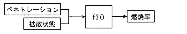
ステップS205では、メイン噴射による燃焼量を推定する。燃焼量の推定には、噴射量、低位発熱量、ペネトレーション及び拡散状態の4つの噴射パラメータの全てを用いる。例えば、燃焼量は、図16に示す数式を用いて算出される。この数式においては、Qburnが燃焼量、αが燃焼率、ρ×QinjがステップS201にて推定した噴射量、AがステップS202にて推定した低位発熱量である。図17に示すように、燃焼率αは、ステップS203にて推定したペネトレーションと、ステップS204にて推定した拡散状態と、に対して所定の関数f3()を用いることで推定される。なお、メイン噴射の噴霧体積も、ペネトレーション及び拡散状態を用いて推定される。また、ステップS205がメイン燃焼量推定部に対応する。また、メイン燃焼の燃焼量をメイン燃焼量と称する。 In step S205, the amount of combustion by main injection is estimated. For the estimation of the combustion amount, all four injection parameters of the injection amount, the lower heating value, the penetration, and the diffusion state are used. For example, the combustion amount is calculated using the mathematical formula shown in FIG. In this equation, Qburn is the combustion amount, α is the combustion rate, ρ × Qinj is the injection amount estimated in step S201, and A is the lower heating value estimated in step S202. As shown in FIG. 17, the combustion rate α is estimated by using a predetermined function f3 () for the penetration estimated in step S203 and the diffusion state estimated in step S204. In addition, the spray volume of the main injection is also estimated using the penetration and the diffusion state. Step S205 corresponds to the main combustion amount estimation unit. Moreover, the combustion amount of main combustion is called main combustion amount.
ステップS206では、メイン噴射による燃焼領域を推定する。燃焼領域は、燃料による燃焼が発生した位置や範囲であり、燃焼領域の推定には、4つの噴射パラメータのうち噴射量、ペネトレーション及び拡散状態の3つを用いる。例えば、噴射量、ペネトレーション及び拡散状態に対して所定の関数やマップ、モデルなどを用いることで燃焼領域を推定する。なお、ステップS206がメイン領域推定部に対応する。また、メイン燃焼の燃焼領域をメイン燃焼領域と称する。 In step S206, the combustion region by main injection is estimated. The combustion region is a position or a range where combustion by the fuel has occurred, and three of the injection parameters, penetration, and diffusion state are used for estimation of the combustion region. For example, the combustion region is estimated by using a predetermined function, map, model, or the like for the injection amount, penetration, and diffusion state. Step S206 corresponds to the main area estimation unit. Further, the combustion region of the main combustion is referred to as a main combustion region.
ステップS207では、燃料噴射弁15から噴射された燃料の位置を示す座標系として燃料座標系を、実混合割合に基づいて設定する。この場合、ステップS207が座標設定部に対応する。図18に示すように、ピストン13の上端面13aには、凹部としてのキャビティ13bが設けられている。燃焼室11aは、キャビティ13bの内部空間を含んで形成されており、燃料噴射弁15は、ピストン13の幅方向において中心位置に配置されている。この場合、ピストン13の幅方向において、燃料噴射弁15の中心線Oとシリンダ19の内周面との離間距離は、ピストン13のボア半径のほぼ1/2になっている。
In step S207, a fuel coordinate system is set based on the actual mixing ratio as a coordinate system indicating the position of the fuel injected from the
燃料座標系は、燃料噴射弁15から噴射された燃料の進行方向に延びた進行軸Nを有している。燃料噴射弁15から噴射された燃料は、燃焼室11aにおいて霧状の噴霧体になり、進行軸Nは、噴霧体が進む向きにおいてその噴霧体の前端部が通ると想定される位置に設定されている。ここで、メイン噴射が行われるタイミングにおいては、筒内温度が十分に高くなっていることに起因して着火遅れが生じにくくなっている。この場合、メイン噴射による噴霧体をメイン噴霧体Fと称すると、メイン噴霧体Fのほぼ全体がメイン燃焼領域を形成しており、メイン燃焼領域を推定することがメイン噴霧体Fの形状や位置を推定することになる。
The fuel coordinate system has a traveling axis N extending in the traveling direction of the fuel injected from the
ここでは、噴射量、低位発熱量、ペネトレーション及び拡散状態に基づいて進行軸Nを設定する。特に、燃焼室11aにおいては、燃料の動粘度や密度などが筒内環境に依存しやすく、その依存度合いは実混合割合によって決まってくる。このため、燃焼室11aでの動粘度や密度を実混合割合に基づいて取得し、この取得結果を考慮して進行軸Nを設定することが、メイン噴霧体Fやアフター噴霧体Gの挙動を考慮して進行軸Nを設定することになる。
Here, the traveling axis N is set based on the injection amount, the lower heating value, the penetration, and the diffusion state. In particular, in the
進行軸Nは、燃料噴射弁15の中心線Oから噴孔の軸線に沿って延びた直線軸部N1と、キャビティ13bの内周面に沿って曲がった曲線軸部N2とを有している。メイン噴射及びアフター噴射が行われるタイミングでは、ピストン13が上死点TDC付近に存在しており、直線軸部N1はキャビティ13bの内周面に向けて延びている。曲線軸部N2は、キャビティ13bの内周面から内側に離間しており、進行軸Nにおいては、直線軸部N1と曲線軸部N2とが互いに交差する部分で接続されている。この場合、進行軸Nは、直線軸部N1が燃料噴射弁15から遠ざかり、曲線軸部N2が燃料噴射弁15に向けて近付く形状になっている。
The traveling axis N has a linear shaft portion N1 extending from the center line O of the
メイン噴射により燃料が噴射された場合、メイン噴霧体Fは、直線軸部N1に沿って燃料噴射弁15から離れる向きに進んだ後、キャビティ13bの内周面にて跳ね返されるように曲線軸部N2に沿って燃料噴射弁15に近付く向きに戻る(図21、図22参照)。ここで、メイン噴霧体Fの挙動は、キャビティ13bの内周面の形状や筒内流速、噴射圧力、噴射量などから影響を受ける。
When fuel is injected by main injection, the main spray body F advances in a direction away from the
ここで、メイン噴霧体Fやアフター噴霧体Gの挙動は、キャビティ13bの形状や筒内環境によって変わることはもちろんのこと、実混合割合によっても変わる。例えば、燃料噴射弁15から噴射された後の燃料の運動量は、動粘度や密度が大きい燃料ほど大きくなる。運動量が大きいほどキャビティ13bの内周面に到達したメイン噴霧体Faの拡散範囲が大きくなりやすく、メイン噴霧体Fやアフター噴霧体Gの前端部がキャビティ13bの内周面に接近しやすい。この場合の進行軸Nを進行軸Naと称すれば、この進行軸Naは、進行軸Nよりもキャビティ13bの内周面に近い位置に配置される。一方、運動量が小さい燃料についての進行軸Nを進行軸Nbと称すれば、この進行軸Nbは、進行軸Nよりもキャビティ13bの内周面から遠い位置に配置される。
Here, the behavior of the main spray body F and the after spray body G varies depending on the actual mixing ratio as well as the shape of the
上記ステップS207では、キャビティ13bの形状に応じたメイン噴霧体Faの挙動を考慮して、メイン噴霧体Faの前端部が通ると想定される経路に進行軸Nを設定する。
In step S207, the traveling axis N is set in a path assumed to pass through the front end of the main spray body Fa in consideration of the behavior of the main spray body Fa according to the shape of the
ステップS208では、メイン噴霧体Faの代表位置F1を取得する。ここでは、メイン噴霧体Faの進む向きにおいて、進行軸N上に存在するメイン噴霧体Faの前側端部を代表位置F1とする。このため、メイン噴霧体Faの前端部が進行軸N上に存在している場合には、その前端部が代表位置F1になる。なお、ステップS208がメイン位置取得部に対応する。 In step S208, the representative position F1 of the main spray body Fa is acquired. Here, the front end of the main spray body Fa existing on the travel axis N in the direction in which the main spray body Fa travels is defined as the representative position F1. For this reason, when the front end portion of the main spray body Fa exists on the traveling axis N, the front end portion becomes the representative position F1. Step S208 corresponds to the main position acquisition unit.
ステップS209では、メイン燃焼後に存在するスモーク量を推定する。スモーク量の推定には、メイン噴射について噴射量、低位発熱量、ペネトレーション及び拡散状態の4つの噴射パラメータを用いる。例えば、噴射量、低位発熱量、ペネトレーション及び拡散状態に対して所定の関数やマップ、モデルなどを用いることで燃焼領域を推定する。 In step S209, the amount of smoke present after main combustion is estimated. For the estimation of the smoke amount, four injection parameters are used for the main injection, namely, the injection amount, the lower heating value, the penetration, and the diffusion state. For example, the combustion region is estimated by using a predetermined function, map, model or the like for the injection amount, the lower heating value, the penetration, and the diffusion state.
なお、この処理で推定するスモーク量には、パイロット噴射に伴って発生するスモーク量が含まれていてもよい。この場合は、パイロット噴射について、噴射量、低位発熱量、ペネトレーション及び拡散状態に基づいてスモーク量を推定する。 Note that the smoke amount estimated in this process may include a smoke amount generated with pilot injection. In this case, for the pilot injection, the smoke amount is estimated based on the injection amount, the lower heating value, the penetration, and the diffusion state.
図7に戻り、メイン推定処理の後、ステップS106に進み、アフター噴射を対象としたアフター推定処理を行う。アフター推定処理については、図19を参照しつつ説明する。ここで、アフター噴射による燃料の燃焼をアフター燃焼と称し、その状態をアフター燃焼状態と称する。この場合、燃料の性状(例えばセタン価)が同一の燃料であっても、その燃料に含まれている分子構造種の混合割合が異なれば、アフター燃焼状態が異なってくる。アフター燃焼が適正に行われることで筒内温度が上昇した場合、メイン燃焼により発生したスモークが酸化しやすくなり、酸化したスモークが燃焼することで内燃機関10の出力が増加する。
Returning to FIG. 7, after the main estimation process, the process proceeds to step S <b> 106, and the after estimation process for after injection is performed. The after estimation process will be described with reference to FIG. Here, the combustion of the fuel by the after injection is referred to as after combustion, and the state is referred to as the after combustion state. In this case, even if the fuel properties (for example, cetane number) are the same, if the mixing ratio of the molecular structural species contained in the fuel is different, the after combustion state will be different. When the in-cylinder temperature rises due to the proper after-combustion, the smoke generated by the main combustion is easily oxidized, and the output of the
図19において、ステップ301〜S304では、実混合割合に基づいてアフター噴射の噴射状態を推定する。アフター噴射の噴射状態を示す噴射パラメータとしては、メイン噴射の噴射パラメータと同様に、噴射量、低位発熱量、ペネトレーション及び拡散状態の4つが挙げられる。基準混合割合を有する基準燃料については、メイン噴射と同様に、アフター噴射に関して筒内環境に応じた各噴射パラメータの値が試験等によりあらかじめ取得されており、これら取得データが基準データとしてメモリ80bに記憶されている。そして、実混合割合を有する実燃料については、アフター噴射に関して基準データと比較することで各噴射パラメータの値を推定する。なお、実燃料についての各噴射パラメータを、基準燃料についての各噴射パラメータとのずれ量に基づいて推定してもよく、実混合割合から直接的に絶対値を算出することで推定してもよい。
In FIG. 19, in steps 301 to S304, the after-injection injection state is estimated based on the actual mixing ratio. As the injection parameters indicating the injection state of the after injection, there are four injection parameters, the lower heating value, the penetration, and the diffusion state, as in the injection parameter of the main injection. For the reference fuel having the reference mixing ratio, as in the case of the main injection, the value of each injection parameter corresponding to the in-cylinder environment for the after injection is acquired in advance by a test or the like, and these acquired data are stored in the
ステップS301〜S304では、ステップS201〜S204でのメイン噴射についての各噴射パラメータの推定処理と同様に、アフター噴射についての各噴射パラメータを推定する。この場合、ステップS301がアフター噴射量推定部に対応し、ステップS302がアフター発熱量推定部に対応し、ステップS303がアフター貫徹力推定部に対応し、ステップS304がアフター拡散推定部に対応する。 In steps S301 to S304, each injection parameter for after-injection is estimated in the same manner as the estimation process for each injection parameter for main injection in steps S201 to S204. In this case, step S301 corresponds to an after injection amount estimation unit, step S302 corresponds to an after heat generation amount estimation unit, step S303 corresponds to an after penetration force estimation unit, and step S304 corresponds to an after diffusion estimation unit.
ステップS305,S306では、ステップS301〜S304にて推定した各噴射パラメータを用いて、アフター燃焼状態を推定する。この燃焼状態を示す燃焼パラメータとしては、メイン燃焼の燃焼パラメータと同様に、燃焼量及び燃焼領域の2つが挙げられる。ここで、基準燃料については、アフター噴射に関して筒内環境に応じた各燃焼パラメータの値が試験等によりあらかじめ取得されており、噴射パラメータと同様に、これら取得データが基準データとしてメモリ80bに記憶されている。そして、実燃料については、アフター噴射に関して基準データと比較することで各燃焼パラメータの値を推定する。なお、実燃料についての各燃焼パラメータを、基準燃料についての各燃焼パラメータとのずれ量に基づいて推定してもよく、実混合割合から直接的に絶対値を算出することで推定してもよい。
In steps S305 and S306, the after-combustion state is estimated using the injection parameters estimated in steps S301 to S304. As the combustion parameters indicating the combustion state, there are two types of combustion parameters, that is, the combustion amount and the combustion region, similarly to the combustion parameters of the main combustion. Here, with respect to the reference fuel, values of each combustion parameter corresponding to the in-cylinder environment regarding after-injection are acquired in advance by a test or the like, and these acquired data are stored as reference data in the
ステップS305,S306では、ステップS205,S206でのメイン噴射についての各燃焼パラメータの推定処理と同様に、アフター噴射についての各燃焼パラメータを推定する。この場合、ステップS305がアフター燃焼量推定部に対応し、ステップS306がアフター領域推定部に対応する。また、アフター燃焼の燃焼量をアフター燃焼量と称し、燃焼領域をアフター燃焼領域と称する。 In steps S305 and S306, each combustion parameter for after-injection is estimated in the same manner as each combustion parameter estimation process for main injection in steps S205 and S206. In this case, step S305 corresponds to the after-burning amount estimation unit, and step S306 corresponds to the after-region estimation unit. Further, the combustion amount of the after combustion is referred to as an after combustion amount, and the combustion region is referred to as an after combustion region.
ここで、アフター噴射が行われるタイミングにおいては、メイン噴射が行われるタイミングと同様に、筒内温度が十分に高くなっていることに起因して着火遅れが生じにくくなっている。この場合、アフター噴射による噴霧体をアフター噴霧体Gと称すると、アフター噴霧体Gのほぼ全体がアフター燃焼領域を形成しており、アフター燃焼領域を推定することがアフター噴霧体Fの形状や位置を推定することになる。 Here, at the timing at which the after injection is performed, similarly to the timing at which the main injection is performed, the ignition delay is less likely to occur due to the sufficiently high in-cylinder temperature. In this case, if the spray body by after-injection is called the after-spray body G, almost the entire after-spray body G forms an after-combustion region, and the shape and position of the after-spray body F can be estimated by estimating the after-combustion region. Will be estimated.
ステップS307では、アフター噴霧体Gの代表位置G1を取得する。ここでは、アフター噴霧体Gの進む向きにおいて、進行軸N上に存在するアフター噴霧体Gの前側端部を代表位置G1とする。このため、アフター噴霧体Gの前端部が進行軸N上に存在している場合には、その前端部が代表位置G1になる。なお、ステップS307がアフター位置取得部に対応する。 In step S307, the representative position G1 of the after spray body G is acquired. Here, in the direction in which the after spray body G advances, the front end of the after spray body G existing on the traveling axis N is set as the representative position G1. For this reason, when the front end part of the after spray body G exists on the advancing axis N, the front end part becomes the representative position G1. Note that step S307 corresponds to the after-position acquisition unit.
図7に戻り、アフター推定処理の後、ステップS107に進み、メイン燃焼領域とアフター燃焼領域との離間距離を燃焼距離L1として算出する。この場合、ステップS107が、メイン燃焼領域とアフター燃焼領域との位置関係を取得する位置取得部、及び代表位置F1,G1の離間距離を取得する距離取得部に対応する。 Returning to FIG. 7, after the after-estimation process, the process proceeds to step S107, and the separation distance between the main combustion area and the after-combustion area is calculated as the combustion distance L1. In this case, step S107 corresponds to a position acquisition unit that acquires the positional relationship between the main combustion region and the after combustion region, and a distance acquisition unit that acquires the separation distance between the representative positions F1 and G1.
ここでは、メイン噴射及びアフター噴射のそれぞれについて、燃料噴射弁15への通電終了から所定時間Δtだけ経過したそれぞれのタイミングta,tbにて、メイン噴霧体Fa及びアフター噴霧体Gaが存在する場合を想定する。タイミングtaでは、図18に示すようにメイン噴霧体Faが存在し、タイミングtbでは、図20に示すようにアフター噴霧体Gaが存在する。この場合、タイミングtbはタイミングtaより後のタイミングになっており(図23参照)、タイミングtaが第1タイミングに相当し、タイミングtbが第2タイミングに相当する。
Here, a case where the main spray body Fa and the after spray body Ga are present at the respective timings ta and tb after a predetermined time Δt has elapsed from the end of energization of the
図20に示すように、進行軸N上においてメイン噴霧体Faの代表位置F1とアフター噴霧体Gaの代表位置G1との離間距離を燃焼距離L1としている。燃焼距離L1は、メイン燃焼領域とアフター燃焼領域との離間距離を示すことになる。 As shown in FIG. 20, the separation distance between the representative position F1 of the main spray body Fa and the representative position G1 of the after spray body Ga on the traveling axis N is defined as a combustion distance L1. The combustion distance L1 indicates a separation distance between the main combustion region and the after combustion region.
ステップS108では、実燃料の燃焼距離L1が適正であるか否かを判定する。ここで、基準燃料について、筒内環境に応じた燃焼距離のデータが試験等によりあらかじめ取得されており、このデータがメモリ80bに記憶されている。ここでは、メモリ80bから基準燃料の燃焼距離を読み込み、この基準燃料の燃焼距離と実燃料の燃焼距離L1との「ずれ」を差分として算出し、この差分が基準距離より小さいか否かを判定する。差分が基準距離より小さくない場合、実燃料の燃焼距離L1が適正でないとして、ステップS109に進む。
In step S108, it is determined whether or not the actual fuel combustion distance L1 is appropriate. Here, with respect to the reference fuel, combustion distance data corresponding to the in-cylinder environment is acquired in advance by a test or the like, and this data is stored in the
ステップS109では、燃焼距離L1の差分が基準距離より小さくなるように、アフター燃焼領域の調整処理を行う。ここでは、実燃料のアフター噴霧体Gaの代表位置G1が基準燃料の代表位置G1よりメイン噴霧体Faの代表位置F1に近い場合に、代表位置G1を進行軸N上において代表位置F1から遠ざける離間処理を行う。また、実燃料の代表位置G1が基準燃料の代表位置G1より代表位置F1から遠い場合に、代表位置G1を代表位置F1に近付ける接近処理を行う。離間処理は、アフター噴霧体Fbの代表位置G1を燃料噴射弁15に近付けるために噴射圧力を小さくする処理や、アフター噴射の時期をTDC側にずらす処理が挙げられる。接近処理としては、アフター噴霧体Fbの代表位置G1を燃料噴射弁15から遠ざけるために噴射圧力を大きくする処理や、アフター噴射の時期をBDC側にずらす処理が挙げられる。
In step S109, after-burning region adjustment processing is performed so that the difference in the combustion distance L1 is smaller than the reference distance. Here, when the representative position G1 of the after spray body Ga of actual fuel is closer to the representative position F1 of the main spray body Fa than the representative position G1 of the reference fuel, the representative position G1 is separated from the representative position F1 on the traveling axis N. Process. Further, when the representative position G1 of the actual fuel is farther from the representative position F1 than the representative position G1 of the reference fuel, an approach process for bringing the representative position G1 closer to the representative position F1 is performed. The separation process includes a process of reducing the injection pressure in order to bring the representative position G1 of the after spray body Fb closer to the
アフター燃焼領域の調整処理においては、燃焼距離Lの差分を基準距離より小さくするための目標値を実混合割合に基づいて設定する。この場合、暫定の目標値を基準混合割合に基づいて取得し、この暫定の目標値を実混合割合を用いて補正することで目標値を算出する。例えば、噴射圧力を小さくする処理においては、噴射圧力の暫定の目標値を、基準混合割合を用いて且つ燃焼距離の差分に基づいて取得し、この暫定の目標値を実混合割合を用いて補正して目標値を算出する。これにより、噴射圧力を大きくする処理を行ったにもかかわらず、実混合割合に起因して噴射量が不足していたということが抑制される。 In the after-burning region adjustment process, a target value for making the difference in the combustion distance L smaller than the reference distance is set based on the actual mixing ratio. In this case, the provisional target value is acquired based on the reference mixing ratio, and the provisional target value is corrected using the actual mixing ratio to calculate the target value. For example, in the process of reducing the injection pressure, the provisional target value of the injection pressure is acquired based on the difference in the combustion distance using the reference mixing ratio, and the provisional target value is corrected using the actual mixing ratio. To calculate a target value. As a result, the fact that the injection amount is insufficient due to the actual mixing ratio is suppressed despite the processing for increasing the injection pressure.
ここで、アフター燃焼によるスモークの酸化について、図21〜図24を参照しつつ説明する。図21に示すように、メイン噴射及びアフター噴射の両方が行われた後、アフター噴霧体Gaが存在しているタイミングtbでは、メイン噴霧体Faを形成していた燃料が時間の経過と共に進行軸Nに沿って移動することでメイン噴霧体Fbが存在している。進行軸Nにおいて、アフター噴霧体Gaとメイン噴霧体Fbとの離間距離を燃焼距離L2と称すれば、この燃焼距離L2は燃焼距離L1より大きくなっている。 Here, the oxidation of smoke by the after combustion will be described with reference to FIGS. As shown in FIG. 21, after both the main injection and the after injection are performed, at the timing tb when the after spray body Ga exists, the fuel that has formed the main spray body Fa progresses along the passage of time. The main spray body Fb exists by moving along N. In the traveling axis N, if the separation distance between the after spray body Ga and the main spray body Fb is referred to as a combustion distance L2, the combustion distance L2 is larger than the combustion distance L1.
図22に示すように、タイミングtbから所定期間だけ経過したタイミングtc(図23参照)では、メイン噴霧体Fb及びアフター噴霧体Gaを形成していた各燃料が進行軸Nに沿って移動することで、メイン噴霧体Fc及びアフター噴霧体Gbを形成している。このタイミングtcでは、アフター噴霧体Gaが燃焼領域を形成していることで筒内温度が上昇し、メイン噴霧体Fcに含まれたスモークが酸化しやすくなっている。 As shown in FIG. 22, at a timing tc (see FIG. 23) after a predetermined period from the timing tb, each fuel that has formed the main spray body Fb and the after spray body Ga moves along the travel axis N. Thus, the main spray body Fc and the after spray body Gb are formed. At this timing tc, the after-spray body Ga forms a combustion region, so that the in-cylinder temperature rises and the smoke contained in the main spray body Fc is easily oxidized.
図23に示すように、パイロット噴射、メイン噴射及びアフター噴射が行われるたびに熱発生率が上昇し、それぞれの噴射の実行に伴って筒内温度が上昇する。また、メイン噴霧体Fの代表位置F1及びアフター噴霧体Gの代表位置G1は、それぞれ時間の経過と共に進行軸Nに沿って進む。 As shown in FIG. 23, every time pilot injection, main injection, and after injection are performed, the heat generation rate increases, and the in-cylinder temperature increases with the execution of each injection. Further, the representative position F1 of the main spray body F and the representative position G1 of the after spray body G advance along the traveling axis N with the passage of time.
図23において、メイン噴霧体Fの代表位置F1については進行軸Nが上方を向いており、アフター噴霧体Gの代表位置G1については進行軸Nが下方を向いている。これら代表位置F1,G1の進行距離を示す線が、タイミングtb,tcの間にて交差している。この交差部分Saは、メイン噴霧体Fとアフター噴霧体Gとの位置関係が、アフター噴霧体Gの燃焼により燃焼室11a中のスモークを酸化させやすい関係になったことを示している。この場合、交差部分Saよりもタイミングtc側において、代表位置F1,G1の進行距離を示す線の間の面積を酸化指標Sと称する。
In FIG. 23, for the representative position F1 of the main spray body F, the travel axis N faces upward, and for the representative position G1 of the after spray body G, the travel axis N faces downward. The lines indicating the travel distances of these representative positions F1 and G1 intersect between timings tb and tc. This intersecting portion Sa indicates that the positional relationship between the main spray body F and the after spray body G is such that the smoke in the
酸化指標Sは、アフター燃焼によるスモークの酸化度合いを示す値である。図24に示すように、燃焼室11a中のスモークがアフター燃焼により低減する度合いを低減率とした場合、このスモーク低減率は、酸化指標Sが大き過ぎても小さ過ぎても低減する。例えば、基準燃料が使用された場合の酸化指標が、スモーク低減率の最も大きくなる酸化指標になっている。
The oxidation index S is a value indicating the degree of smoke oxidation due to after combustion. As shown in FIG. 24, when the degree of reduction of smoke in the
図7に戻り、ステップS110では、メモリ80bから基準燃料の燃焼量を読み込み、この基準燃料の燃焼量と実燃料の燃焼量との「ずれ」を差分として算出し、この差分があらかじめ定められた基準量より小さいか否かを判定する。この場合の差分は、基準燃料の燃焼量と実燃料の燃焼量との差の絶対値である。
Returning to FIG. 7, in step S110, the combustion amount of the reference fuel is read from the
ここで、アフター噴射による燃焼量の目標値は、ステップS209にて推定されたメイン燃焼後のスモーク量に応じて設定され、差分の判定基準は燃焼量の目標値に応じて設定される。例えば、スモーク量が多いほど燃焼量の目標値が大きい値に設定される。この場合、差分の基準量が目標値の所定率に設定されると、この目標値が大きいほど差分の基準量が大きい値に設定されることになる。 Here, the target value of the combustion amount by the after injection is set according to the smoke amount after the main combustion estimated in step S209, and the determination criterion for the difference is set according to the target value of the combustion amount. For example, the target value of the combustion amount is set to a larger value as the smoke amount increases. In this case, when the difference reference amount is set to a predetermined rate of the target value, the difference reference amount is set to a larger value as the target value is larger.
燃焼量の差分が基準量より小さくない場合、ステップS111に進み、燃焼量の差分が基準量より小さくなるように、アフター燃焼量の調整処理を行う。ここでは、実燃料のアフター燃焼量が基準アフター燃焼量より小さい場合に、燃焼量を増加させるための増加処理を行い、実燃料のアフター燃焼量が基準燃料のアフター燃焼量より大きい場合に、アフター燃焼量を減少させるための減少処理を行う。増加処理としては、アフター噴射について、噴射量を増加させる処理や、噴射圧を上昇させる処理、噴射時期をピストン13の上死点TDC側にずらす処理、EGR率を低下させる処理などが挙げられる。減少処理としては、アフター噴射について、噴射量を減少させる処理や、噴射圧を低下させる処理、噴射時期をピストン13の化死点BDC側にずらす処理、EGR率を増加させる処理などが挙げられる。
When the difference in the combustion amount is not smaller than the reference amount, the process proceeds to step S111, and after-burning amount adjustment processing is performed so that the difference in the combustion amount becomes smaller than the reference amount. Here, when the after-burning amount of the actual fuel is smaller than the reference after-burning amount, an increase process is performed to increase the combustion amount. When the after-burning amount of the actual fuel is larger than the after-burning amount of the reference fuel, the after-burning amount is increased. A reduction process is performed to reduce the amount of combustion. Examples of the increase process include a process for increasing the injection amount, a process for increasing the injection pressure, a process for shifting the injection timing to the top dead center TDC side of the
燃焼量の調整処理においては、燃焼量の差分を基準量より小さくするための目標値を実混合割合に基づいて設定する。この場合、暫定の目標値を基準混合割合に基づいて取得し、この暫定の目標値を実混合割合を用いて補正することで、目標値を算出する。例えば、噴射量を増加させる処理においては、噴射量の暫定の目標値を、基準混合割合を用いて且つ燃焼量の差分に基づいて取得し、この暫定の目標値を実混合割合を用いて補正することで目標値を算出する。これにより、噴射量を増加させる処理を行ったにもかかわらず、実混合割合に起因して噴射量が不足していたということが抑制される。 In the adjustment process of the combustion amount, a target value for making the difference in the combustion amount smaller than the reference amount is set based on the actual mixing ratio. In this case, the provisional target value is acquired based on the reference mixing ratio, and the provisional target value is corrected using the actual mixing ratio, thereby calculating the target value. For example, in the process of increasing the injection amount, the provisional target value of the injection amount is acquired based on the difference in the combustion amount using the reference mixing ratio, and the provisional target value is corrected using the actual mixing ratio. To calculate the target value. This suppresses the fact that the injection amount is insufficient due to the actual mixing ratio despite the processing for increasing the injection amount.
なお、ステップS109,S111が燃焼制御部に対応する。 Steps S109 and S111 correspond to the combustion control unit.
ここで、1燃焼サイクルにおいては、筒内温度の上昇中に行われるパイロット噴射、メイン噴射、アフター噴射、筒内温度の低下中に行われるポスト噴射が、この順番で行われる。筒内酸素濃度は、パイロット噴射が行われるタイミングが最も大きく、メイン噴射、アフター噴射の順で小さくなり、ポスト噴射が行われるタイミングが最も小さくなる。 Here, in one combustion cycle, pilot injection performed while the in-cylinder temperature is rising, main injection, after-injection, and post-injection performed while the in-cylinder temperature is decreasing are performed in this order. The in-cylinder oxygen concentration has the largest timing at which pilot injection is performed, decreases in the order of main injection and after injection, and has the minimum timing at which post injection is performed.
筒内温度は、吸気開始後のパイロット噴射が行われるタイミングが最も低い低温であり、メイン噴射及びアフター噴射が行われるタイミングで十分に高い高温に上昇する。その後、筒内温度は、ピストンの膨張行程においてシリンダ容積の増加に伴って低下するが、ポスト噴射が行われるタイミングではパイロット噴射が行われるタイミングよりも高い中温になっている。燃焼室11aにおいては、例えば低温域を900K以下とし、中温域を900K〜1100Kとし、高温域が1100K以上とする。
The in-cylinder temperature is a low temperature at which the timing at which pilot injection is performed after the start of intake is the lowest, and rises to a sufficiently high temperature at the timing at which main injection and after injection are performed. Thereafter, the in-cylinder temperature decreases as the cylinder volume increases in the expansion stroke of the piston, but the intermediate temperature is higher at the timing when the post injection is performed than when the pilot injection is performed. In the
1燃焼サイクルにおいては、燃料の噴射に伴ってOHラジカルが発生することで、ケトンやアルデヒド等の燃焼性分子の酸化により化学的な燃焼が開始される。OHラジカルを発生させる反応としては、不活性HO2ラジカルとアルケンから生成された過酸化水素H2O2がOHラジカルに分解される分解反応と、炭化水素に酸素が付与され、燃焼性分子が生成される過程でOHラジカルの生成及び消費を繰り返す連鎖分岐反応とが挙げられる。連鎖分岐反応については、OHラジカルの生成量と消費量とがほぼ同じであり、OHラジカルに寄与する成分を推定することは、燃焼性分子の生成量を推定することと同義である。 In one combustion cycle, OH radicals are generated as fuel is injected, so that chemical combustion is started by oxidation of combustible molecules such as ketones and aldehydes. Reactions that generate OH radicals include a decomposition reaction in which hydrogen peroxide H 2 O 2 generated from an inactive HO 2 radical and an alkene is decomposed into OH radicals, oxygen is added to the hydrocarbon, and flammable molecules are A chain branching reaction that repeats generation and consumption of OH radicals in the process of generation. Regarding the chain branching reaction, the amount of OH radicals produced and consumed are almost the same, and estimating the component that contributes to OH radicals is synonymous with estimating the amount of combustible molecules produced.
燃料の各分子構造種には、連鎖分岐反応の過程でOHラジカルを生成しやすい生成分子と、OHラジカルを生成しにくいインヒビター分子とが含まれている。生成分子としては直鎖パラフィン類があり、インヒビター分子としては芳香族類がある。燃料においては、連鎖分岐反応だけでなくどの場合でも、生成分子とインヒビター分子との密度分布に応じて着火のしやすさが異なる。ただし、高温域においてH2O2の分解が過剰の場合は、OHラジカルの生成状態と噴霧内外の流体的な乱れとに応じて着火時期が変化する。生成分子とインヒビター分子との密度分布は、連鎖分岐反応により生成されるOHラジカル分布の時系列に沿った発生位置に影響を与えるものであり、連鎖分岐反応の発生態様は燃料成分に相関しているといえる。 Each molecular structural species of the fuel includes a generated molecule that easily generates OH radicals in the course of the chain branching reaction and an inhibitor molecule that does not easily generate OH radicals. The generated molecules include straight-chain paraffins, and the inhibitor molecules include aromatics. In the fuel, the ease of ignition differs depending on the density distribution between the generated molecules and the inhibitor molecules in any case, not only in the chain branching reaction. However, when the decomposition of H 2 O 2 is excessive in a high temperature range, the ignition timing changes according to the generation state of OH radicals and the fluid disturbance inside and outside the spray. The density distribution of the generated molecule and the inhibitor molecule affects the generation position along the time series of the OH radical distribution generated by the chain branching reaction, and the generation mode of the chain branching reaction is correlated with the fuel component. It can be said that.
燃料の噴射に伴う着火の生じやすさは、その時の筒内温度がどの温度域にあるのかによって変わる。図25に示すように、筒内温度が900K以下の低温域においては、H2O2が分解されにくく、H2O2の分解反応によるOHラジカルの生成量が非常に少ない。その一方で、燃料成分のうち、分子内異性化により水素を引き抜き歪エネルギーの小さい構造を持つことができる成分による連鎖分岐反応が発生しやすく、この連鎖分岐反応に関わるOHラジカルの生成量が比較的多くなっている。この場合、生成分子が数多く存在していることで連鎖分岐反応が発生しやすく、H2O2の分解反応は発生しにくい。 The ease of ignition associated with fuel injection varies depending on which temperature range the in-cylinder temperature is at. As shown in FIG. 25, in the low temperature range where the in-cylinder temperature is 900K or less, H 2 O 2 is hardly decomposed, and the amount of OH radicals generated by the decomposition reaction of H 2 O 2 is very small. On the other hand, among the fuel components, a chain branching reaction is likely to occur due to a component that can extract hydrogen by intramolecular isomerization and have a low strain energy, and the amount of OH radicals involved in this chain branching reaction is compared. It is becoming more and more popular. In this case, a chain branching reaction is likely to occur due to the presence of many generated molecules, and the decomposition reaction of H 2 O 2 is unlikely to occur.
これに対して、発明者らは、パイロット噴射が行われる温度域である低温域では、燃料成分に対する着火時期の依存度が高いという知見を得た。この場合、実混合割合によっては、高温時のH2O2分解に伴うOHラジカル生成とβ開裂により炭素数が1〜3個(C1〜C3)のケトンやアルデヒド等の燃焼性分子に強制的に分解されて着火が行われる場合に比べて、着火遅れが生じやすくなる。 On the other hand, the inventors have obtained the knowledge that the dependence of the ignition timing on the fuel component is high in the low temperature range where the pilot injection is performed. In this case, depending on the actual mixing ratio, OH radical generation and β-cleavage accompanying H 2 O 2 decomposition at high temperature may be forced on combustible molecules such as ketones and aldehydes having 1 to 3 carbon atoms (C1 to C3). Compared to the case where ignition is performed after being disassembled, ignition delay is likely to occur.
低温域から筒内温度が高くなるにつれて、連鎖分岐反応によるOHラジカルの生成量が徐々に減少するとともに、H2O2の分解反応によるOHラジカルの生成量が急激に増加する。 As the in-cylinder temperature increases from a low temperature region, the amount of OH radicals generated by the chain branching reaction gradually decreases, and the amount of OH radicals generated by the decomposition reaction of H 2 O 2 increases rapidly.
例えば、筒内温度が900K〜1100Kの中温域においては、H2O2が分解しやすくなっているものの、H2O2の分解反応によるOHラジカルの生成量が温度上昇に伴っても急増はしていない。この場合、燃料成分による連鎖分岐反応によって生成するOHラジカルに比べ、H2O2の分解反応によるOHラジカルの生成量が多くなる。そして、連鎖分岐反応が起こる歪エネルギーの小さい構造を形成する前に炭素数1〜3個の構造を持つ分子が増加し、連鎖分岐反応は徐々に減少する。 For example, in the intermediate temperature range of the in-cylinder temperature of 900K to 1100K, H 2 O 2 is easily decomposed, but the rapid increase is also caused when the amount of OH radicals generated by the decomposition reaction of H 2 O 2 is increased. Not done. In this case, the amount of OH radicals generated by the decomposition reaction of H 2 O 2 is larger than that of OH radicals generated by a chain branching reaction with fuel components. And before forming a structure with small strain energy where chain branching reaction occurs, the number of molecules having 1 to 3 carbon atoms increases, and chain branching reaction gradually decreases.
これに対して、発明者らは、ポスト噴射が行われる温度域である中温域での着火時期について、連鎖分岐反応を起こす燃料成分としての生成分子に依存する着火遅れと、生成分子等の燃料成分に感度を持たないH2O2の分解反応による着火遅れとを考慮する必要がある、という知見を得た。このため、中温域においては、燃料成分に対する着火時期の依存度がパイロット噴射の行われる低温域に比べて低く、実混合割合によっては、ポスト噴射の方がパイロット噴射に比べて着火遅れが生じにくくなる。 On the other hand, the inventors have determined that the ignition timing in the intermediate temperature range where the post-injection is performed, the ignition delay depending on the generated molecules as the fuel component causing the chain branching reaction, and the fuel such as generated molecules. It was found that it is necessary to consider the ignition delay due to the decomposition reaction of H 2 O 2 having no sensitivity to the components. For this reason, in the intermediate temperature range, the dependence of the ignition timing on the fuel component is lower than in the low temperature range where pilot injection is performed, and depending on the actual mixing ratio, the post injection is less likely to cause an ignition delay than the pilot injection. Become.
また、筒内温度が1100K以上の高温域においては、H2O2が分解しやすく、H2O2の分解反応によるOHラジカルの生成量が温度上昇に伴って急激に増加している。その一方で、燃料成分による連鎖分岐反応を起こす分子が減少し、連鎖分岐反応によるOHラジカルの生成量が非常に少なくなっている。これに対して、発明者らは、メイン噴射やアフター噴射が行われる温度域である高温域では、着火時期が燃料の化学的な燃焼に影響されることがほぼない、という知見を得た。このため、実混合割合によっては、メイン噴射やアフター噴射の方がポスト噴射に比べて着火遅れが生じにくくなる。 In addition, in a high temperature range where the in-cylinder temperature is 1100 K or higher, H 2 O 2 is easily decomposed, and the amount of OH radicals generated by the decomposition reaction of H 2 O 2 increases rapidly as the temperature rises. On the other hand, the number of molecules that cause a chain branching reaction due to the fuel component is reduced, and the amount of OH radicals generated by the chain branching reaction is very small. On the other hand, the inventors have obtained the knowledge that the ignition timing is hardly influenced by the chemical combustion of the fuel in the high temperature range where the main injection and after injection are performed. For this reason, depending on the actual mixing ratio, ignition delay is less likely to occur in main injection and after injection than in post injection.
ここまで説明した第1実施形態の作用効果を、以下に説明する。 The operational effects of the first embodiment described so far will be described below.
第1実施形態によれば、実燃料のメイン燃焼領域及びアフター燃焼領域が実混合割合に基づいて個別に推定される。このため、メイン噴射とアフター噴射とで筒内環境等が異なっていることに起因して、メイン燃焼領域とアフター燃焼領域とで実混合割合から受ける影響が異なっていたとしても、これら燃焼領域の相対的な位置関係を適正に管理できる。この場合、メイン燃焼領域とアフター燃焼領域とが互いに近いことでアフター燃焼が不完全燃焼になってスモークの発生量が増加するということや、これら燃焼領域が互いに遠いことでアフター燃焼によるスモークの酸化率が低下するということを抑制できる。したがって、様々な性状を有する燃料のいずれが使用された場合でも、アフター噴射により排気エミッションや内燃機関10の出力を適正化できる。
According to the first embodiment, the main combustion region and the after combustion region of the actual fuel are individually estimated based on the actual mixing ratio. For this reason, even if the main combustion region and the after combustion region have different effects from the actual mixing ratio due to the difference in the in-cylinder environment and the like between the main injection and the after injection, these combustion regions The relative positional relationship can be properly managed. In this case, the main combustion region and the after-combustion region are close to each other, resulting in incomplete combustion resulting in an increased amount of smoke, and the fact that these combustion regions are far from each other, the oxidation of smoke due to after-combustion. It can suppress that a rate falls. Therefore, even if any of the fuels having various properties is used, the exhaust emission and the output of the
第1実施形態によれば、メイン噴射及びアフター噴射のそれぞれについて、噴射量、低位発熱量、ペネトレーション及び拡散状態という4つの噴射パラメータを用いてメイン燃焼状態及びアフター燃焼状態が推定されている。この場合、例えば、実混合割合に対して関数やマップ、モデルを用いてメイン燃焼状態が直接的に推定される構成に比べて、関数やマップ、モデルに関する推定結果の依存度を低くすることや、関数やマップ、モデルの作成難易度を下げることが可能になる。このため、メイン燃焼状態やアフター燃焼状態の推定精度を高めることができる。 According to the first embodiment, for each of the main injection and the after injection, the main combustion state and the after combustion state are estimated using the four injection parameters of the injection amount, the lower heating value, the penetration, and the diffusion state. In this case, for example, compared to a configuration in which the main combustion state is directly estimated using the function, map, or model with respect to the actual mixing ratio, the dependence of the estimation result on the function, map, or model is reduced. It is possible to reduce the difficulty of creating functions, maps, and models. For this reason, the estimation accuracy of the main combustion state and the after combustion state can be increased.
第1実施形態によれば、アフター燃焼領域やアフター燃焼量の調整処理が実混合割合に基づいて行われるため、これら調整処理を行ったにもかかわらず燃焼距離Lや燃焼量の「ずれ」が基準距離や基準量内に含まれない、という事態の発生を抑制できる。このため、実混合割合を用いることでメイン噴射及びアフター噴射についての燃焼量や燃焼領域の推定精度を高めた構成において、その高い推定精度を内燃機関10の制御に有効に活用できる。
According to the first embodiment, the adjustment process of the after-burning region and the after-burning amount is performed based on the actual mixing ratio. It is possible to suppress the occurrence of a situation in which it is not included in the reference distance or the reference amount. For this reason, in the configuration in which the estimation accuracy of the combustion amount and the combustion region for the main injection and the after injection is increased by using the actual mixing ratio, the high estimation accuracy can be effectively used for the control of the
第1実施形態によれば、燃料座標系の座標軸として進行軸Nが実混合割合に基づいて設定されているため、実混合割合に関係なく1つの座標軸が設定された構成に比べて、代表位置F1,G1の取得精度を高めることができる。これは、メイン噴霧体F及びアフター噴霧体Gについて、それぞれの前端部が代表位置F1,G1になるように進行軸Nが設定されていることで、噴霧体における相対的な位置をメイン噴霧体Fとアフター噴霧体Gとでほぼ同じにできるためである。 According to the first embodiment, since the traveling axis N is set as the coordinate axis of the fuel coordinate system based on the actual mixing ratio, the representative position is compared with the configuration in which one coordinate axis is set regardless of the actual mixing ratio. The acquisition accuracy of F1 and G1 can be increased. For the main spray body F and the after spray body G, the traveling axis N is set so that the front ends of the main spray body F and the after spray body G are representative positions F1 and G1, respectively. This is because F and the after spray body G can be made substantially the same.
第1実施形態によれば、メイン噴霧体Fの代表位置F1及びアフター噴霧体Gの代表位置G1が個別に取得されるため、メイン燃焼領域とアフター燃焼領域との相対的な位置関係を数値化することができる。したがって、これら燃焼領域の位置関係を管理する上で処理負担を低減することが可能になる。 According to the first embodiment, since the representative position F1 of the main spray body F and the representative position G1 of the after spray body G are acquired separately, the relative positional relationship between the main combustion region and the after combustion region is quantified. can do. Therefore, it is possible to reduce the processing burden in managing the positional relationship between these combustion regions.
第1実施形態によれば、メイン噴射及びアフター噴射から所定時間Δtだけ経過したタイミングta,tbにて、メイン噴霧体Faの代表位置F1及びアフター噴霧体Gaの代表値G1が取得される。この場合、メイン噴射及びアフター噴射のそれぞれが受ける筒内環境の影響が極力小さい段階で代表位置F1,G1が取得されるため、取得精度を高めることができる。例えば、タイミングtbにて代表位置F1,G1の両方が取得される構成では、タイミングtbでのメイン噴霧体Fbが筒内流速など筒内環境の影響を大きく受けていると考えられ、このメイン噴霧体Fbの代表位置F1の取得精度が低下しやすい。 According to the first embodiment, the representative position F1 of the main spray body Fa and the representative value G1 of the after spray body Ga are acquired at timings ta and tb after a predetermined time Δt has elapsed from the main injection and after injection. In this case, since the representative positions F1 and G1 are acquired at a stage where the influence of the in-cylinder environment received by each of the main injection and the after injection is as small as possible, the acquisition accuracy can be improved. For example, in the configuration in which both the representative positions F1 and G1 are acquired at the timing tb, it is considered that the main spray body Fb at the timing tb is greatly affected by the in-cylinder environment such as the in-cylinder flow velocity. The acquisition accuracy of the representative position F1 of the body Fb tends to decrease.
(第2実施形態)
上記第1実施形態では、メイン噴射及びアフター噴射について、代表位置F1,G1がそれぞれの燃焼領域を用いて取得されていたが、第2実施形態では、代表位置F1,G1がそれぞれのペネトレーション及び拡散状態を用いて取得される。ここでは、本実施形態のアフター制御処理について図26〜図28のフローチャートを参照しつつ説明する。
(Second Embodiment)
In the first embodiment, the representative positions F1 and G1 are acquired using the respective combustion regions for the main injection and the after injection. However, in the second embodiment, the representative positions F1 and G1 are obtained from the respective penetration and diffusion. Obtained using state. Here, the after-control processing of this embodiment will be described with reference to the flowcharts of FIGS.
図26において、ステップS401〜S406では、上記第1実施形態のステップS101〜S106と同じ処理を行う。ただし、ステップS405のメイン推定処理、及びステップS406のアフター推定処理については、燃焼量及び燃焼領域という2つの燃焼パラメータの推定を行わない。なお、ステップS401が混合取得部に対応する。 In FIG. 26, in steps S401 to S406, the same processing as in steps S101 to S106 of the first embodiment is performed. However, in the main estimation process in step S405 and the after-estimation process in step S406, the two combustion parameters of the combustion amount and the combustion region are not estimated. Note that step S401 corresponds to the mixture acquisition unit.
メイン推定処理については、図27において、ステップS501〜S503にて、上記第1実施形態のステップS201,S203,S204と同じ処理を行う。なお、ステップS502が、メイン噴射についてのペネトレーションを推定する貫徹力推定部に対応する。 As for the main estimation process, the same processes as steps S201, S203, and S204 of the first embodiment are performed in steps S501 to S503 in FIG. Note that step S502 corresponds to a penetrating force estimation unit that estimates the penetration of the main injection.
ステップS504では、メイン噴射についての噴射量、ペネトレーション及び拡散状態に基づいてメイン噴霧体Fの形状や位置を推定する。例えば、噴射量、ペネトレーション及び拡散状態に対して所定の関数やマップ、モデルなどを用いることでメイン噴霧体Fを推定する。ここでは、少なくともタイミングta,tb,tcについてのメイン噴霧体Fの形状や位置を推定する。なお、噴射量、ペネトレーション及び拡散状態の少なくとも1つを用いることでメイン噴霧体Fを推定してもよい。 In step S504, the shape and position of the main spray body F are estimated based on the injection amount, penetration, and diffusion state for the main injection. For example, the main spray body F is estimated by using a predetermined function, map, model, or the like for the injection amount, penetration, and diffusion state. Here, the shape and position of the main spray body F at least at timings ta, tb, and tc are estimated. Note that the main spray body F may be estimated by using at least one of the injection amount, the penetration, and the diffusion state.
ステップS505,S506では、上記第1実施形態のステップS207,S208と同じ処理を行う。なお、ステップS506は、メイン噴霧体Fの代表位置F1を取得するメイン位置取得部に対応する。 In steps S505 and S506, the same processing as in steps S207 and S208 of the first embodiment is performed. Step S506 corresponds to a main position acquisition unit that acquires the representative position F1 of the main spray body F.
アフター推定処理については、図28において、ステップS601〜S603にて、上記第1実施形態のステップS301,S303,S304と同じ処理を行う。なお、ステップS602が、アフター噴射についてのペネトレーションを推定する貫徹力推定部に対応する。 As for the after-estimation process, the same processes as steps S301, S303, and S304 of the first embodiment are performed in steps S601 to S603 in FIG. Note that step S602 corresponds to a penetrating force estimation unit that estimates penetration for after-injection.
ステップS604では、アフター噴射についての噴射量、ペネトレーション及び拡散状態に基づいてアフター噴霧体Gの位置や形状を推定する。例えば、噴射量、ペネトレーション及び拡散状態に対して所定の関数やマップ、モデルなどを用いることでアフター噴霧体Gを推定する。ここでは、少なくともタイミングtb,tcについてのアフター噴霧体Gの形状や位置を推定する。なお、メイン噴霧体Fと同様に、噴射量、ペネトレーション及び拡散状態の少なくとも1つを用いることでアフター噴霧体Gを推定してもよい。 In step S604, the position and shape of the after spray body G are estimated based on the injection amount, penetration, and diffusion state of the after injection. For example, the after spray body G is estimated by using a predetermined function, map, model, or the like for the injection amount, penetration, and diffusion state. Here, the shape and position of the after spray body G at least at timings tb and tc are estimated. Similarly to the main spray body F, the after spray body G may be estimated by using at least one of the injection amount, the penetration, and the diffusion state.
ステップS605では、上記第1実施形態のステップS307と同じ処理を行う。なお、ステップS605は、アフター噴霧体Gの代表位置G1を取得するアフター位置取得部に対応する。 In step S605, the same processing as step S307 in the first embodiment is performed. Step S605 corresponds to an after position acquisition unit that acquires the representative position G1 of the after spray body G.
図26に戻り、アフター推定処理の後、ステップS407では、メイン噴射のペネトレーションとアフター噴射のペネトレーションとの差分を、メイン噴射を基準としたペネトレーション減少量として取得する。 Returning to FIG. 26, after the after estimation process, in step S407, the difference between the penetration of the main injection and the penetration of the after injection is acquired as a penetration reduction amount based on the main injection.
ステップS408では、ペネトレーション減少量が適正であるか否かを判定する。ここで、基準燃料について、筒内環境に応じたペネトレーション減少量のデータが試験等によりあらかじめ取得されており、このデータがメモリ80bに記憶されている。ここでは、メモリ80bから基準燃料のペネトレーション減少量を読み込み、この基準燃料のペネトレーション減少量と実燃料のペネトレーション減少量との「ずれ」を差分として算出し、この差分が基準量より小さいか否かを判定する。差分が基準量より小さくない場合、実燃料のペネトレーション減少量が適正でないとして、ステップS409に進む。
In step S408, it is determined whether or not the penetration reduction amount is appropriate. Here, with respect to the reference fuel, the data of the penetration reduction amount corresponding to the in-cylinder environment is acquired in advance by a test or the like, and this data is stored in the
ステップS409では、ペネトレーション減少量の差分が基準量より小さくなるように、アフター噴射のペネトレーションについて調整処理を行う。ここでは、実燃料のペネトレーション減少量が基準燃料のペネトレーション減少量より大きい場合には、噴射量を減少させる処理や、燃料の噴射段数を増加させる処理、噴射圧力を減少させる処理などを行う。この場合、アフター噴射の燃料がメイン燃焼領域に突入しにくくなり、アフター噴射の燃料が不完全燃焼に陥ることが抑制されるため、排気エミッションが適正化される。 In step S409, adjustment processing is performed for the penetration of after injection so that the difference in the penetration reduction amount is smaller than the reference amount. Here, when the penetration reduction amount of the actual fuel is larger than the penetration reduction amount of the reference fuel, processing for decreasing the injection amount, processing for increasing the number of fuel injection stages, processing for decreasing the injection pressure, and the like are performed. In this case, after-injection fuel is less likely to enter the main combustion region, and after-injection fuel is prevented from falling into incomplete combustion, so that exhaust emission is optimized.
一方、実燃料のペネトレーション減少量が基準燃料のペネトレーション減少量より小さい場合には、噴射量を増加させる処理や、燃料の噴射段数を減少させる処理、噴射圧力を増加させる処理などを行う。この場合、アフター噴射の燃料がメイン燃焼領域に接近しやすくなり、メイン燃焼により生じたスモークの酸化が促されるため、内燃機関10の出力が適正に増加する。
On the other hand, when the penetration reduction amount of the actual fuel is smaller than the penetration reduction amount of the reference fuel, processing for increasing the injection amount, processing for decreasing the number of fuel injection stages, processing for increasing the injection pressure, and the like are performed. In this case, the fuel of after-injection is likely to approach the main combustion region and the oxidation of smoke generated by the main combustion is promoted, so that the output of the
第2実施形態によれば、メイン噴射のペネトレーション及びアフター噴射のペネトレーションが実混合割合に基づいて推定される。このため、メイン噴射とアフター噴射とで筒内環境等が異なっていることに起因して、メイン噴射とアフター噴射とでペネトレーションが実混合割合から受ける影響が異なっていたとしても、これらペネトレーションの相対関係を適正に管理できる。この場合、上記第1実施形態と同様に、アフター噴射によるスモークの発生量が増加するということや、アフター噴射によるスモークの酸化率が低下するということを抑制できる。 According to the second embodiment, the penetration of the main injection and the penetration of the after injection are estimated based on the actual mixing ratio. For this reason, even if the main injection and the after injection have different effects on the actual mixing ratio due to the difference in the in-cylinder environment between the main injection and the after injection, the relative of these penetrations Manage relationships properly. In this case, similarly to the first embodiment, it is possible to suppress an increase in the amount of smoke generated by after-injection and a decrease in the smoke oxidation rate by after-injection.
(他の実施形態)
以上、発明の好ましい実施形態について説明したが、発明は上述した実施形態に何ら制限されることなく、以下に例示するように種々変形して実施することが可能である。各実施形態で具体的に組合せが可能であることを明示している部分同士の組合せばかりではなく、特に組合せに支障が生じなければ、明示してなくとも実施形態同士を部分的に組み合せることも可能である。
(Other embodiments)
The preferred embodiments of the present invention have been described above, but the present invention is not limited to the above-described embodiments, and various modifications can be made as illustrated below. Not only combinations of parts that clearly show that combinations are possible in each embodiment, but also combinations of the embodiments even if they are not explicitly stated unless there is a problem with the combination. Is also possible.
変形例1として、混合割合推定部82が、複数の燃焼特性値に基づき分子構造種の混合割合を推定するのではなく、燃料の一般性状をセンサで検出し、その検出結果に基づき上記混合割合を推定してもよい。上記一般性状の具体例としては、燃料の密度、動粘度、蒸留温度等が挙げられる。
As a modified example 1, the mixing
また、混合割合推定部82による推定結果と、上記センサの検出結果の両方に基づいて、上記混合割合を推定してもよい。例えば、推定結果及び検出結果のいずれか一方に基づいて推定された混合割合を、他方に基づいて補正すればよい。また、分子構造種に応じて異なる手法で推定してもよい。例えば、第1の分子構造種の混合割合については、混合割合推定部82による推定結果に基づいて推定し、第2の分子構造種の混合割合については、上記センサの検出結果に基づいて推定する。
Further, the mixing ratio may be estimated based on both the estimation result by the mixing
変形例2として、燃料に含まれた分子構造種の混合割合を推定するのではなく、燃料に含まれている水素や炭素、硫黄、窒素、酸素といった成分の混合割合を推定してもよい。例えば、平均炭素数や平均水素数、水素数と炭素数との比であるHC比などが、水素や炭素についての混合割合として挙げられる。この構成では、各種成分の混合割合に基づいて、噴射量等の噴射パラメータや燃焼量等の燃焼パラメータが推定される。この場合、実燃料に含まれた成分が異なっていたり成分の混合割合が異なっていたりしても、今回のメイン噴射およびアフター噴射による燃焼状態を適正に推定できる。なお、平均炭素数等の燃料成分を中間パラメータと称することもできる。 As a modified example 2, instead of estimating the mixing ratio of the molecular structural species contained in the fuel, the mixing ratio of components such as hydrogen, carbon, sulfur, nitrogen, and oxygen contained in the fuel may be estimated. For example, the average carbon number, the average hydrogen number, the HC ratio that is the ratio between the hydrogen number and the carbon number, and the like can be cited as the mixing ratio for hydrogen and carbon. In this configuration, an injection parameter such as an injection amount and a combustion parameter such as a combustion amount are estimated based on the mixing ratio of various components. In this case, even if the components contained in the actual fuel are different or the mixing ratios of the components are different, the combustion state by the current main injection and after injection can be properly estimated. The fuel component such as the average carbon number can also be referred to as an intermediate parameter.
変形例3として、上記第1実施形態のステップS109等の調整処理や、上記第2実施形態のステップ409の調整処理が、実混合割合に基づいて行われるのではなく、実混合割合に関係なく行われてもよい。例えば、上記第1実施形態において、ステップS206,S306にて実混合割合に基づいて燃焼領域が推定された後、ステップS109において、燃焼領域を調整するために目標噴射圧力等が実混合割合に関係なく設定される構成とする。
As
変形例4として、メイン噴射及びアフター噴射について、燃焼量等の燃焼パラメータを、噴射量等の4つの噴射パラメータの少なくとも1つを用いて推定してもよい。例えば、燃焼領域をペネトレーションだけを用いて推定する。この場合でも、4つの噴射パラメータが互いに相関関係にあることに起因して、燃焼領域を推定する上である程度の推定精度を確保することができる。 As a fourth modification, for main injection and after injection, a combustion parameter such as a combustion amount may be estimated using at least one of four injection parameters such as an injection amount. For example, the combustion region is estimated using only penetration. Even in this case, a certain degree of estimation accuracy can be ensured in estimating the combustion region due to the correlation between the four injection parameters.
変形例5として、ポスト燃焼について、低位発熱量を噴射パラメータとして用いるのではなく、高位発熱量を噴射パラメータとして用いてもよい。また、低位発熱量及び高位発熱量の両方を含んだ発熱量を噴射パラメータとして用いてもよい。 As a fifth modification, instead of using the lower heating value as the injection parameter for post-combustion, the higher heating value may be used as the injection parameter. Further, a heat generation amount including both a low heat generation amount and a high heat generation amount may be used as the injection parameter.
変形例6として、実混合割合及び基準混合割合のそれぞれについて、噴射量等の噴射パラメータや燃焼量等の燃焼パラメータを個別に推定しなくてもよい。例えば、実混合割合と基準混合割合との差分を算出し、この差分に基づいて噴射パラメータや燃焼パラメータの差分を推定する。この場合、基準燃料の燃焼状態と実燃料の燃焼状態との「ずれ」を直接的に推定することになる。 As a sixth modification, it is not necessary to individually estimate the injection parameter such as the injection amount and the combustion parameter such as the combustion amount for each of the actual mixing ratio and the reference mixing ratio. For example, the difference between the actual mixing ratio and the reference mixing ratio is calculated, and the difference between the injection parameter and the combustion parameter is estimated based on this difference. In this case, the “deviation” between the combustion state of the reference fuel and the combustion state of the actual fuel is directly estimated.
変形例7として、上記第1実施形態において、燃焼量等の燃焼パラメータを噴射量等の噴射パラメータを用いずに推定してもよい。例えば、燃焼量を、噴射パラメータに基づいて推定するのではなく、筒内圧センサ21の検出信号及び実混合割合に基づいて推定する。この場合でも、燃焼量の推定に燃料の実混合割合を反映させることができる。 As a modified example 7, in the first embodiment, the combustion parameter such as the combustion amount may be estimated without using the injection parameter such as the injection amount. For example, the combustion amount is not estimated based on the injection parameter, but is estimated based on the detection signal of the in-cylinder pressure sensor 21 and the actual mixing ratio. Even in this case, the actual fuel mixing ratio can be reflected in the estimation of the combustion amount.
変形例8として、メイン推定処置やアフター推定処理において、噴射パラメータとして、着火遅れ特性を推定してもよい。着火遅れ特性は、着火しやすさを示す特性であり、例えば、筒内環境が着火を促す状態にある場合について、燃料の着火が開始されるまでに要する時間で表現されるものである。筒内環境が着火を促す状態としては、例えば、筒内温度及び筒内圧が着火の発生にとって十分に高くなっている状態などが挙げられる。この場合、例えば燃焼量を、燃焼率を、ペネトレーション、拡散状態及び着火遅れ特定に基づいて推定してもよい。 As a modified example 8, the ignition delay characteristic may be estimated as the injection parameter in the main estimation process or the after-estimation process. The ignition delay characteristic is a characteristic indicating the ease of ignition. For example, when the in-cylinder environment is in a state of prompting ignition, the ignition delay characteristic is expressed by the time required for starting the ignition of fuel. Examples of the state in which the in-cylinder environment promotes ignition include a state in which the in-cylinder temperature and the in-cylinder pressure are sufficiently high for the occurrence of ignition. In this case, for example, the combustion amount may be estimated based on the penetration rate, the diffusion state, and the ignition delay specification.
変形例9として、上記第2実施形態において、メイン噴射及びアフター噴射のそれぞれについて、実混合割合に基づいて燃料の噴射領域を推定してもよい。例えば、メイン推定処理及びアフター推定処置においては、メイン噴射及びアフター噴射のそれぞれについてペネトレーション及び拡散状態を推定し、これらペネトレーション及び拡散状態に基づいて噴射領域を推定する。そして、アフター制御処理においては、実燃料の噴射領域と基準燃料の噴射領域との「ずれ」を差分として算出し、この差分に基づいて噴射領域を調整する調整処理を行う。 As a modified example 9, in the second embodiment, the fuel injection region may be estimated based on the actual mixing ratio for each of the main injection and the after injection. For example, in the main estimation process and the after estimation process, the penetration and the diffusion state are estimated for each of the main injection and the after injection, and the injection region is estimated based on the penetration and the diffusion state. Then, in the after-control process, the “deviation” between the injection region of the actual fuel and the injection region of the reference fuel is calculated as a difference, and an adjustment process for adjusting the injection region based on this difference is performed.
変形例10として、噴霧体F,Gの前側端部が代表位置F1,G1とされるのではなく、噴霧体F,Gの中間位置や後側端部が代表位置F1,G1とされていてもよい。特に、進行軸Nに直交する方向を噴霧体F,Gの幅方向とした場合に、その幅方向において噴霧体F,Gの中心位置を代表位置F1,G1とする。ここで、幅方向において噴霧体F,Gの中心位置は、実混合割合や筒内環境によって変化しやすいと考えられる。このため、幅方向において噴霧体F,Gの中心位置を代表位置F1,G1とした構成では、進行軸Nを実混合割合に基づいて設定していることで、代表位置F1,G1の推定精度を適正に保つことができる。 As a tenth modification, the front end portions of the spray bodies F and G are not set as the representative positions F1 and G1, but the intermediate position and the rear end portion of the spray bodies F and G are set as the representative positions F1 and G1. Also good. In particular, when the direction perpendicular to the traveling axis N is the width direction of the spray bodies F and G, the center positions of the spray bodies F and G are set as the representative positions F1 and G1 in the width direction. Here, it is considered that the center positions of the spray bodies F and G in the width direction are likely to change depending on the actual mixing ratio and the in-cylinder environment. For this reason, in the configuration in which the central positions of the spray bodies F and G in the width direction are the representative positions F1 and G1, the traveling axis N is set based on the actual mixing ratio, so that the estimation accuracy of the representative positions F1 and G1 is increased. Can be kept appropriate.
変形例11として、燃料座標系は実混合割合に関係なく設定されてもよい。例えば、進行軸Nが、噴孔の延び方向とキャビティ13bの内周面の形状とに基づいて設定された構成とする。ここで、実混合割合や筒内環境が変わっても噴霧体F,Gの前側端部の位置は変わりにくいと考えられる。このため、噴霧体F,Gの前側端部の位置が代表位置F1,G1とされている構成では、進行軸Nが実混合割合に関係なく設定されても、代表位置F1,G1の取得精度が低下しにくくなっている。
As a modified example 11, the fuel coordinate system may be set regardless of the actual mixing ratio. For example, the traveling axis N is set based on the extending direction of the nozzle hole and the shape of the inner peripheral surface of the
変形例12として、代表位置F1,G1は、噴霧体F,Gごとに異なる位置に設定されてもよい。例えば、メイン噴霧体Fについては前側端部を代表位置F1とし、アフター噴霧体Gについては後側端部を代表位置G1とする。この場合でも、代表位置F1,G1の離間距離を算出することで、噴霧体F,Gの位置関係を取得できる。 As a modified example 12, the representative positions F1 and G1 may be set at different positions for the spray bodies F and G, respectively. For example, for the main spray body F, the front end is the representative position F1, and for the after spray body G, the rear end is the representative position G1. Even in this case, the positional relationship between the spray bodies F and G can be acquired by calculating the separation distance between the representative positions F1 and G1.
変形例13として、上記第1実施形態において、燃焼距離L1に基づいてアフター燃焼領域の調整処理を行うのではなく、この調整処理を燃焼距離L2に基づいて行ってもよい。すなわち、タイミングta,tbという異なるタイミングでの噴霧体Fa,Gaについて代表位置F1,G1を比較するのではなく、同一のタイミングtbでの噴霧体Fb,Gbについて代表位置F1,G1を比較する。この場合でも、代表位置F1,G1を用いてメイン噴霧体Fとアフター噴霧体Gとの位置関係を取得していることになる。 As a modified example 13, in the first embodiment, instead of performing the after-burning region adjustment process based on the combustion distance L1, this adjustment process may be performed based on the combustion distance L2. That is, the representative positions F1 and G1 are not compared for the spray bodies Fa and Ga at different timings of timing ta and tb, but the representative positions F1 and G1 are compared for the spray bodies Fb and Gb at the same timing tb. Even in this case, the positional relationship between the main spray body F and the after spray body G is acquired using the representative positions F1 and G1.
変形例14として、燃料の一般性状を検出する性状センサが設けられていてもよい。例えば、燃料の動粘度や密度を検出する性状センサが燃料タンクやコモンレールに設けられた構成とする。この構成では、燃料の平均炭素数や平均水素数が、性状センサの検出結果に基づいて推定されてもよい。 As a modified example 14, a property sensor for detecting the general property of the fuel may be provided. For example, a property sensor that detects the kinematic viscosity and density of the fuel is provided in the fuel tank and the common rail. In this configuration, the average carbon number and average hydrogen number of the fuel may be estimated based on the detection result of the property sensor.
変形例15として、筒内温度は、温度検出素子21aにより検出されるのではなく、筒内圧センサ21により検出された筒内圧に基づき推定してもよい。具体的には、筒内温度を、筒内圧力、シリンダ容積、シリンダ内のガス重量、ガス定数から演算して推定する。
As a
変形例16として、燃焼システムの推定装置及び制御装置としてのECU80が提供する手段および/または機能は、実体的な記憶媒体に記録されたソフトウェアおよびそれを実行するコンピュータ、ソフトウェアのみ、ハードウェアのみ、あるいはそれらの組合せによって提供することができる。例えば、燃焼システムの制御装置がハードウェアである回路によって提供される場合、それは多数の論理回路を含むデジタル回路、またはアナログ回路によって提供することができる。
As a modified example 16, means and / or functions provided by the
10…内燃機関、11a…燃焼室、80…ECU(推定装置、制御装置)。
DESCRIPTION OF
Claims (8)
前記内燃機関での燃焼に用いる燃料に含まれた各種成分の混合割合を取得する混合取得部(S101,S401)と、
前記燃料がメイン噴射により前記内燃機関の燃焼室(11a)に噴射されることで発生するメイン燃焼について、前記燃料の燃焼領域をメイン燃焼領域として、前記混合取得部により取得された前記混合割合に基づいて推定するメイン領域推定部(S206)と、
1燃焼サイクル中の前記メイン噴射の後において、前記燃料がアフター噴射により前記燃焼室に噴射されることで発生するアフター燃焼について、前記燃料の噴射領域をアフター燃焼領域として、前記混合割合に基づいて推定するアフター領域推定部(S306)と、
前記メイン燃焼領域及び前記アフター燃焼領域の位置を取得するための燃料座標系を、前記混合割合に基づいて設定する座標設定部(S207)と、
前記座標設定部により設定された前記燃料座標系において、前記メイン燃焼領域の所定の代表位置(F1)を取得するメイン位置取得部(S208)と、
前記燃料座標系において、前記アフター燃焼領域の所定の代表位置(G1)を取得するアフター位置取得部(S307)と、
を備えている燃焼システムの推定装置。 An estimation device (80) applied to a combustion system having an internal combustion engine (10),
A mixture acquisition unit (S101, S401) for acquiring a mixing ratio of various components contained in fuel used for combustion in the internal combustion engine;
For the main combustion that occurs when the fuel is injected into the combustion chamber (11a) of the internal combustion engine by main injection, the fuel combustion region is set as the main combustion region, and the mixing ratio acquired by the mixing acquisition unit A main region estimation unit (S206) for estimation based on
After the main injection in one combustion cycle, after combustion that occurs when the fuel is injected into the combustion chamber by after injection, the fuel injection region is defined as the after combustion region, based on the mixing ratio. An after-region estimation unit (S306) to be estimated;
A coordinate setting unit (S207) for setting a fuel coordinate system for acquiring the positions of the main combustion region and the after combustion region based on the mixing ratio;
A main position acquisition unit (S208) for acquiring a predetermined representative position (F1) of the main combustion region in the fuel coordinate system set by the coordinate setting unit;
An after position acquisition unit (S307) for acquiring a predetermined representative position (G1) of the after combustion region in the fuel coordinate system;
An estimation device for a combustion system.
前記アフター位置取得部は、前記アフター噴射の終了から前記所定時間だけ経過した第2タイミング(tb)での前記アフター燃焼領域の代表位置を取得するものである請求項1〜3のいずれか1つに記載の燃焼システムの推定装置。 The main position acquisition unit acquires a representative position of the main combustion region at a first timing (ta) after a predetermined time (Δt) has elapsed since the end of the main injection,
The after position acquisition unit, any one of claims 1 to 3, wherein it is intended to obtain a representative position of the after-combustion zone in the second timing (tb) has elapsed for the predetermined time period from the end of the post-injection An estimation device for a combustion system according to claim 1.
前記メイン燃焼における前記燃料の発熱量を、前記混合割合に基づいて推定するメイン発熱量推定部(S202)と、
前記メイン噴射による前記燃料の貫徹力を、前記混合割合に基づいて推定するメイン貫徹力推定部(S203)と、
前記メイン噴射による前記燃料の拡散状態を、前記混合割合に基づいて推定するメイン拡散推定部(S204)と、
の少なくとも1つを備え、
前記メイン領域推定部は、前記メイン噴射についての前記噴射量、前記発熱量、前記貫徹力及び前記拡散状態の少なくとも1つに基づいて、前記メイン燃焼領域を推定する請求項1〜4のいずれか1つに記載の燃焼システムの推定装置。 A main injection amount estimation unit (S201) for estimating the injection amount by the main injection based on the mixing ratio;
A main calorific value estimation unit (S202) for estimating the calorific value of the fuel in the main combustion based on the mixing ratio;
A main penetration force estimation unit (S203) for estimating the penetration force of the fuel by the main injection based on the mixing ratio;
A main diffusion estimation unit (S204) for estimating a diffusion state of the fuel by the main injection based on the mixing ratio;
Comprising at least one of
The main region estimation unit, the injection quantity for said main injection, the amount of heat generated, the penetration and based on at least one of the diffusion state claim 1-4 for estimating the main combustion zone The estimation apparatus of the combustion system as described in one.
前記アフター燃焼における前記燃料の発熱量を、前記混合割合に基づいて推定するアフター発熱量推定部(S302)と、
前記アフター噴射による前記燃料の貫徹力を、前記混合割合に基づいて推定するアフター貫徹力推定部(S303)と、
前記アフター噴射による前記燃料の拡散状態を、前記混合割合に基づいて推定するアフター拡散推定部(S304)と、
の少なくとも1つを備え、
前記アフター領域推定部は、前記アフター噴射についての前記噴射量、前記発熱量、前記貫徹力及び前記拡散状態の少なくとも1つに基づいて、前記アフター燃焼領域を推定する請求項1〜5のいずれか1つに記載の燃焼システムの推定装置。 An after-injection amount estimating unit (S301) for estimating the injection amount by the after-injection based on the mixing ratio;
An after-heat generation amount estimation unit (S302) for estimating the heat generation amount of the fuel in the after-combustion based on the mixing ratio;
An after penetration force estimating unit (S303) for estimating the penetration force of the fuel by the after injection based on the mixing ratio;
An after-diffusion estimating unit (S304) for estimating the diffusion state of the fuel by the after-injection based on the mixing ratio;
Comprising at least one of
The after region estimation unit, the injection quantity for said after-injection, the amount of heat generated, the penetration and based on at least one of the diffusion state claim 1-5 for estimating the after-combustion zone The estimation apparatus of the combustion system as described in one.
Priority Applications (3)
| Application Number | Priority Date | Filing Date | Title |
|---|---|---|---|
| JP2015222313A JP6477433B2 (en) | 2015-11-12 | 2015-11-12 | Combustion system estimation device |
| PCT/JP2016/076879 WO2017081931A1 (en) | 2015-11-12 | 2016-09-13 | Estimation device and control device for combustion system |
| US15/773,590 US10794321B2 (en) | 2015-11-12 | 2016-09-13 | Estimation device and control device for combustion system |
Applications Claiming Priority (1)
| Application Number | Priority Date | Filing Date | Title |
|---|---|---|---|
| JP2015222313A JP6477433B2 (en) | 2015-11-12 | 2015-11-12 | Combustion system estimation device |
Publications (2)
| Publication Number | Publication Date |
|---|---|
| JP2017089545A JP2017089545A (en) | 2017-05-25 |
| JP6477433B2 true JP6477433B2 (en) | 2019-03-06 |
Family
ID=58695078
Family Applications (1)
| Application Number | Title | Priority Date | Filing Date |
|---|---|---|---|
| JP2015222313A Expired - Fee Related JP6477433B2 (en) | 2015-11-12 | 2015-11-12 | Combustion system estimation device |
Country Status (3)
| Country | Link |
|---|---|
| US (1) | US10794321B2 (en) |
| JP (1) | JP6477433B2 (en) |
| WO (1) | WO2017081931A1 (en) |
Families Citing this family (6)
| Publication number | Priority date | Publication date | Assignee | Title |
|---|---|---|---|---|
| US11719152B2 (en) * | 2011-12-16 | 2023-08-08 | Transportation Ip Holdings, Llc | Multivariable dynamic control system of a multi-fuel engine |
| JP6436064B2 (en) * | 2015-11-12 | 2018-12-12 | 株式会社デンソー | Deposit estimation apparatus and combustion system control apparatus |
| JP6439659B2 (en) * | 2015-11-12 | 2018-12-19 | 株式会社デンソー | Combustion system estimation device and control device |
| JP6485489B2 (en) * | 2017-05-23 | 2019-03-20 | マツダ株式会社 | ENGINE CONTROL DEVICE AND ENGINE CONTROL METHOD |
| JP7054716B2 (en) * | 2020-03-18 | 2022-04-14 | 本田技研工業株式会社 | Internal combustion engine boost pressure control device |
| DE102021202000A1 (en) * | 2021-03-02 | 2022-09-08 | Hyundai Motor Company | FUEL INJECTION SYSTEM FOR AN INTERNAL COMBUSTION ENGINE AND METHOD AND CONTROL DEVICE FOR CONTROLLING A FUEL INJECTION SYSTEM OF AN INTERNAL COMBUSTION ENGINE |
Family Cites Families (9)
| Publication number | Priority date | Publication date | Assignee | Title |
|---|---|---|---|---|
| JP4122870B2 (en) | 2002-07-12 | 2008-07-23 | トヨタ自動車株式会社 | Fuel supply device for internal combustion engine |
| JP4321561B2 (en) * | 2006-07-20 | 2009-08-26 | トヨタ自動車株式会社 | In-cylinder injection spark ignition internal combustion engine control device |
| KR101081787B1 (en) | 2006-07-20 | 2011-11-09 | 도요타 지도샤(주) | Control apparatus and control method for direct injection spark ignition internal combustion engine |
| DE102008000916B4 (en) | 2007-04-02 | 2021-12-16 | Denso Corporation | Combustion control device for direct injection compression ignition engines |
| JP2008267274A (en) * | 2007-04-20 | 2008-11-06 | Toyota Motor Corp | Direct injection engine control system |
| US8516991B2 (en) * | 2008-04-24 | 2013-08-27 | Toyota Jidosha Kabushiki Kaisha | Multi-fuel internal combustion engine |
| JP2012241638A (en) * | 2011-05-20 | 2012-12-10 | Nippon Soken Inc | Fuel injection control device of internal combustion engine |
| JP2012255392A (en) * | 2011-06-09 | 2012-12-27 | Toyota Motor Corp | Device for detecting deterioration in fuel consumption of compression ignition internal combustion engine, and control device |
| JP6032231B2 (en) * | 2014-03-07 | 2016-11-24 | 株式会社デンソー | Fuel property detection device |
-
2015
- 2015-11-12 JP JP2015222313A patent/JP6477433B2/en not_active Expired - Fee Related
-
2016
- 2016-09-13 WO PCT/JP2016/076879 patent/WO2017081931A1/en active Application Filing
- 2016-09-13 US US15/773,590 patent/US10794321B2/en not_active Expired - Fee Related
Also Published As
| Publication number | Publication date |
|---|---|
| JP2017089545A (en) | 2017-05-25 |
| US10794321B2 (en) | 2020-10-06 |
| US20180320627A1 (en) | 2018-11-08 |
| WO2017081931A1 (en) | 2017-05-18 |
Similar Documents
| Publication | Publication Date | Title |
|---|---|---|
| JP6477433B2 (en) | Combustion system estimation device | |
| JP6477434B2 (en) | Combustion system estimation device | |
| JP6477432B2 (en) | Combustion system estimation device | |
| JP6477435B2 (en) | Combustion system estimation device | |
| JP2017002845A (en) | Fuel estimation device | |
| d’Ambrosio et al. | Potential of multiple injection strategies implementing the after shot and optimized with the design of experiments procedure to improve diesel engine emissions and performance | |
| JP6421702B2 (en) | Combustion system controller | |
| Kolbeck | Closed loop combustion control-enabler of future refined engine performance regarding power, efficiency, emissions & NVH under stringent governmental regulations | |
| JP2006226188A (en) | Fuel property detection device of diesel engine | |
| JP6439660B2 (en) | Combustion system estimation device and control device | |
| WO2017081994A1 (en) | Smoke amount estimation device and combustion system control device | |
| JP6384458B2 (en) | Combustion system controller | |
| JP6361537B2 (en) | Fuel property discrimination device | |
| EP2415995A1 (en) | Control device for internal combustion engine | |
| JP6439659B2 (en) | Combustion system estimation device and control device | |
| WO2017081992A1 (en) | Lubricity estimation device and fuel supply control device | |
| US10047692B2 (en) | GDCI cold start misfire prevention | |
| CN108368787A (en) | Method and apparatus for the internal combustion engine for running the especially motor vehicle with dual fuel injection | |
| Meyer et al. | Improved Combustion Control in Diesel Engines Through Active Oxygen Concentration Compensation | |
| Schaub et al. | Cylinder pressure based fuel path control for non-conventional combustion modes | |
| JP2009041532A (en) | Fuel injection control device for diesel engine | |
| GB2575092A (en) | Controller for a fuel injection system | |
| JP2016138516A (en) | Fuel injection control device |
Legal Events
| Date | Code | Title | Description |
|---|---|---|---|
| A621 | Written request for application examination |
Free format text: JAPANESE INTERMEDIATE CODE: A621 Effective date: 20170727 |
|
| A131 | Notification of reasons for refusal |
Free format text: JAPANESE INTERMEDIATE CODE: A131 Effective date: 20180703 |
|
| A521 | Request for written amendment filed |
Free format text: JAPANESE INTERMEDIATE CODE: A523 Effective date: 20180830 |
|
| A131 | Notification of reasons for refusal |
Free format text: JAPANESE INTERMEDIATE CODE: A131 Effective date: 20181030 |
|
| A521 | Request for written amendment filed |
Free format text: JAPANESE INTERMEDIATE CODE: A523 Effective date: 20181214 |
|
| TRDD | Decision of grant or rejection written | ||
| A01 | Written decision to grant a patent or to grant a registration (utility model) |
Free format text: JAPANESE INTERMEDIATE CODE: A01 Effective date: 20190108 |
|
| A61 | First payment of annual fees (during grant procedure) |
Free format text: JAPANESE INTERMEDIATE CODE: A61 Effective date: 20190121 |
|
| R151 | Written notification of patent or utility model registration |
Ref document number: 6477433 Country of ref document: JP Free format text: JAPANESE INTERMEDIATE CODE: R151 |
|
| R250 | Receipt of annual fees |
Free format text: JAPANESE INTERMEDIATE CODE: R250 |
|
| R250 | Receipt of annual fees |
Free format text: JAPANESE INTERMEDIATE CODE: R250 |
|
| LAPS | Cancellation because of no payment of annual fees |