JP6449255B2 - 電力端子コネクタ - Google Patents
電力端子コネクタ Download PDFInfo
- Publication number
- JP6449255B2 JP6449255B2 JP2016516573A JP2016516573A JP6449255B2 JP 6449255 B2 JP6449255 B2 JP 6449255B2 JP 2016516573 A JP2016516573 A JP 2016516573A JP 2016516573 A JP2016516573 A JP 2016516573A JP 6449255 B2 JP6449255 B2 JP 6449255B2
- Authority
- JP
- Japan
- Prior art keywords
- power terminal
- terminal
- flexible
- power
- connector
- Prior art date
- Legal status (The legal status is an assumption and is not a legal conclusion. Google has not performed a legal analysis and makes no representation as to the accuracy of the status listed.)
- Active
Links
- 239000004020 conductor Substances 0.000 claims description 69
- 239000002184 metal Substances 0.000 claims description 6
- 229910052751 metal Inorganic materials 0.000 claims description 6
- RYGMFSIKBFXOCR-UHFFFAOYSA-N Copper Chemical compound [Cu] RYGMFSIKBFXOCR-UHFFFAOYSA-N 0.000 description 8
- 229910052802 copper Inorganic materials 0.000 description 8
- 239000010949 copper Substances 0.000 description 8
- 238000003466 welding Methods 0.000 description 5
- 238000000034 method Methods 0.000 description 4
- 238000010586 diagram Methods 0.000 description 3
- 239000000463 material Substances 0.000 description 3
- 238000004146 energy storage Methods 0.000 description 2
- 238000012986 modification Methods 0.000 description 2
- 230000004048 modification Effects 0.000 description 2
- 230000000717 retained effect Effects 0.000 description 2
- 238000003780 insertion Methods 0.000 description 1
- 230000037431 insertion Effects 0.000 description 1
- 230000013011 mating Effects 0.000 description 1
- 238000003825 pressing Methods 0.000 description 1
- 230000007704 transition Effects 0.000 description 1
Images


Classifications
-
- H—ELECTRICITY
- H01—ELECTRIC ELEMENTS
- H01R—ELECTRICALLY-CONDUCTIVE CONNECTIONS; STRUCTURAL ASSOCIATIONS OF A PLURALITY OF MUTUALLY-INSULATED ELECTRICAL CONNECTING ELEMENTS; COUPLING DEVICES; CURRENT COLLECTORS
- H01R11/00—Individual connecting elements providing two or more spaced connecting locations for conductive members which are, or may be, thereby interconnected, e.g. end pieces for wires or cables supported by the wire or cable and having means for facilitating electrical connection to some other wire, terminal, or conductive member, blocks of binding posts
- H01R11/11—End pieces or tapping pieces for wires, supported by the wire and for facilitating electrical connection to some other wire, terminal or conductive member
- H01R11/28—End pieces consisting of a ferrule or sleeve
- H01R11/281—End pieces consisting of a ferrule or sleeve for connections to batteries
- H01R11/288—Interconnections between batteries
-
- H—ELECTRICITY
- H01—ELECTRIC ELEMENTS
- H01M—PROCESSES OR MEANS, e.g. BATTERIES, FOR THE DIRECT CONVERSION OF CHEMICAL ENERGY INTO ELECTRICAL ENERGY
- H01M50/00—Constructional details or processes of manufacture of the non-active parts of electrochemical cells other than fuel cells, e.g. hybrid cells
- H01M50/50—Current conducting connections for cells or batteries
- H01M50/502—Interconnectors for connecting terminals of adjacent batteries; Interconnectors for connecting cells outside a battery casing
- H01M50/521—Interconnectors for connecting terminals of adjacent batteries; Interconnectors for connecting cells outside a battery casing characterised by the material
- H01M50/526—Interconnectors for connecting terminals of adjacent batteries; Interconnectors for connecting cells outside a battery casing characterised by the material having a layered structure
-
- H—ELECTRICITY
- H01—ELECTRIC ELEMENTS
- H01M—PROCESSES OR MEANS, e.g. BATTERIES, FOR THE DIRECT CONVERSION OF CHEMICAL ENERGY INTO ELECTRICAL ENERGY
- H01M50/00—Constructional details or processes of manufacture of the non-active parts of electrochemical cells other than fuel cells, e.g. hybrid cells
- H01M50/50—Current conducting connections for cells or batteries
- H01M50/502—Interconnectors for connecting terminals of adjacent batteries; Interconnectors for connecting cells outside a battery casing
- H01M50/521—Interconnectors for connecting terminals of adjacent batteries; Interconnectors for connecting cells outside a battery casing characterised by the material
- H01M50/522—Inorganic material
-
- H—ELECTRICITY
- H01—ELECTRIC ELEMENTS
- H01M—PROCESSES OR MEANS, e.g. BATTERIES, FOR THE DIRECT CONVERSION OF CHEMICAL ENERGY INTO ELECTRICAL ENERGY
- H01M50/00—Constructional details or processes of manufacture of the non-active parts of electrochemical cells other than fuel cells, e.g. hybrid cells
- H01M50/50—Current conducting connections for cells or batteries
- H01M50/528—Fixed electrical connections, i.e. not intended for disconnection
-
- H—ELECTRICITY
- H01—ELECTRIC ELEMENTS
- H01R—ELECTRICALLY-CONDUCTIVE CONNECTIONS; STRUCTURAL ASSOCIATIONS OF A PLURALITY OF MUTUALLY-INSULATED ELECTRICAL CONNECTING ELEMENTS; COUPLING DEVICES; CURRENT COLLECTORS
- H01R11/00—Individual connecting elements providing two or more spaced connecting locations for conductive members which are, or may be, thereby interconnected, e.g. end pieces for wires or cables supported by the wire or cable and having means for facilitating electrical connection to some other wire, terminal, or conductive member, blocks of binding posts
- H01R11/03—Individual connecting elements providing two or more spaced connecting locations for conductive members which are, or may be, thereby interconnected, e.g. end pieces for wires or cables supported by the wire or cable and having means for facilitating electrical connection to some other wire, terminal, or conductive member, blocks of binding posts characterised by the relationship between the connecting locations
- H01R11/05—Individual connecting elements providing two or more spaced connecting locations for conductive members which are, or may be, thereby interconnected, e.g. end pieces for wires or cables supported by the wire or cable and having means for facilitating electrical connection to some other wire, terminal, or conductive member, blocks of binding posts characterised by the relationship between the connecting locations the connecting locations having different types of direct connections
-
- H—ELECTRICITY
- H01—ELECTRIC ELEMENTS
- H01R—ELECTRICALLY-CONDUCTIVE CONNECTIONS; STRUCTURAL ASSOCIATIONS OF A PLURALITY OF MUTUALLY-INSULATED ELECTRICAL CONNECTING ELEMENTS; COUPLING DEVICES; CURRENT COLLECTORS
- H01R13/00—Details of coupling devices of the kinds covered by groups H01R12/70 or H01R24/00 - H01R33/00
- H01R13/02—Contact members
- H01R13/15—Pins, blades or sockets having separate spring member for producing or increasing contact pressure
- H01R13/187—Pins, blades or sockets having separate spring member for producing or increasing contact pressure with spring member in the socket
-
- H—ELECTRICITY
- H01—ELECTRIC ELEMENTS
- H01R—ELECTRICALLY-CONDUCTIVE CONNECTIONS; STRUCTURAL ASSOCIATIONS OF A PLURALITY OF MUTUALLY-INSULATED ELECTRICAL CONNECTING ELEMENTS; COUPLING DEVICES; CURRENT COLLECTORS
- H01R35/00—Flexible or turnable line connectors, i.e. the rotation angle being limited
- H01R35/02—Flexible line connectors without frictional contact members
-
- H—ELECTRICITY
- H01—ELECTRIC ELEMENTS
- H01R—ELECTRICALLY-CONDUCTIVE CONNECTIONS; STRUCTURAL ASSOCIATIONS OF A PLURALITY OF MUTUALLY-INSULATED ELECTRICAL CONNECTING ELEMENTS; COUPLING DEVICES; CURRENT COLLECTORS
- H01R4/00—Electrically-conductive connections between two or more conductive members in direct contact, i.e. touching one another; Means for effecting or maintaining such contact; Electrically-conductive connections having two or more spaced connecting locations for conductors and using contact members penetrating insulation
- H01R4/02—Soldered or welded connections
- H01R4/023—Soldered or welded connections between cables or wires and terminals
-
- Y—GENERAL TAGGING OF NEW TECHNOLOGICAL DEVELOPMENTS; GENERAL TAGGING OF CROSS-SECTIONAL TECHNOLOGIES SPANNING OVER SEVERAL SECTIONS OF THE IPC; TECHNICAL SUBJECTS COVERED BY FORMER USPC CROSS-REFERENCE ART COLLECTIONS [XRACs] AND DIGESTS
- Y02—TECHNOLOGIES OR APPLICATIONS FOR MITIGATION OR ADAPTATION AGAINST CLIMATE CHANGE
- Y02E—REDUCTION OF GREENHOUSE GAS [GHG] EMISSIONS, RELATED TO ENERGY GENERATION, TRANSMISSION OR DISTRIBUTION
- Y02E60/00—Enabling technologies; Technologies with a potential or indirect contribution to GHG emissions mitigation
- Y02E60/10—Energy storage using batteries
Landscapes
- Chemical & Material Sciences (AREA)
- Chemical Kinetics & Catalysis (AREA)
- Electrochemistry (AREA)
- General Chemical & Material Sciences (AREA)
- Inorganic Chemistry (AREA)
- Connection Of Batteries Or Terminals (AREA)
- Connector Housings Or Holding Contact Members (AREA)
Description
一部の公知の電力端子コネクタは、ナットおよびボルト接続部の長い組み付け時間およびトルクの問題を克服するための、迅速接続タイプのコネクタである。例えば、各バッテリは、ピンまたはブレードを有することができ、バッテリ間のジャンパは、ケーブルの各端部に、電力端子コネクタ、または隣接するバッテリのピンまたはブレードに押し付けられてこれらの間で電気接続を行う他の相互接続部品を備える。電力端子コネクタは通常、ばねコンタクトを受容する端子本体を有する。ばねコンタクトは、端子本体とバッテリの電力端子との間に電力経路を形成する。このようなジャンパは、多くの部品を含み、通常はナットおよびボルトタイプのコネクタよりも高価である。
代替実施形態では、可撓性導体150は可撓性の編組線を備えることができる。他の代替実施形態では、可撓性導体150は、積み重なった多層の金属シートを有することができる。例えば、シートを複数回折り畳んで、積重体(stack-up)を形成することができる。積重体の折り目の数が、可撓性導体150の通電能力を制御し、折り目が多いほど(例えば積重体が厚いほど)、通電能力を高くすることができる。加えて、折り畳むことにより、薄い可撓性シートを使用することができ、しかも高い通電能力を可能にする。場合により、層を重ね合わせてもよい。すべての露出した導体がカバーまたはハウジングで絶縁されることを理解されたい。
例えば、タブ230は各々、第1の縁部242および第2の縁部244と、第1の縁部242および第2の縁部244の間に延びる第1の側部246および第2の側部248とを備える。第1の縁部242および第2の縁部244と第1の側部246および第2の側部248とは各々、端子本体200との少なくとも1つの接触点を有して、端子本体200とコンタクトばね204との間に電力経路を作る。例えば、第1の縁部242および第2の縁部244はポスト218に係合する。第1の側部246は前端部212に係合する。第2の側部248は張出し縁部240に係合する。さらに、第1のバンド224は端子本体200に係合して、端子本体200との1つまたは複数の接触点を作る。各接触点は、コンタクトばね204と端子本体200との間に電力経路を画定する。コンタクトばね204と端子本体200との間に多くの接触点があると、そのような境界面にわたる抵抗が小さくなり、より高い電流が境界面にわたって流れることができる。
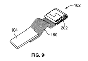
102 電力端子コネクタ
104、105 電力端子
106、108 バッテリ
110 上部
112 前部
114 側部
116 切欠き領域
120 上部
122 底部
124 先端
150 可撓性導体
152 雌型端子
160 第1の取付部
162 第2の取付部
164 可撓性部分
180 第1の脚部
182 第2の脚部
200 端子本体
202 レセプタクル
204 コンタクトばね
206 上壁
208 底壁
210 側壁
212 前端部
214 後端部
216 切欠き
218 ポスト
220 前端部
222 後端部
224、226 円周バンド
228 ばね梁
230 タブ
232 間隙
234 タブ幅
236 切欠き幅
240 張出し縁部
242 第1の縁部
244 第2の縁部
246 第1の側部
248 第2の側部
250 内面
300 過大応力隆起
302、304 コンタクト隆起
350 可撓性導体
352 雌型端子
360 可撓性導体
370 電力端子コネクタ
372 雌型端子
374 可撓性導体、ケーブル
376 端子本体
378 コンタクトばね
Claims (10)
- 第1のバッテリモジュール(106)の平板状の第1の電力端子(104)に直接終端される第1の取付部(160)と、第2の取付部(162)と、前記第1の取付部と前記第2の取付部との間の可撓性部分(164)と、を有する可撓性導体(150)と、
前記第2の取付部に結合され、端子本体(200)と、コンタクトばね(204)と、を有する雌型端子(152)と、
を備える電力端子コネクタ(102)であって、
前記端子本体(200)は、第2のバッテリモジュール(108)の平板状の第2の電力端子(105)を受容するように構成されたレセプタクル(202)を有し、
前記端子本体(200)が、前記第2の取付部に終端されて前記端子本体を前記可撓性導体に機械的および電気的に接続し、
前記端子本体(200)が、前記レセプタクルに対して開口し、前記第2のバッテリモジュールの前記第2の電力端子を貫通させて受容するように構成された開口前端部(212)を有するとともに、
前記コンタクトばね(204)は、前記レセプタクルに受容されて前記端子本体に電気的に接続されており、かつ、
前記コンタクトばね(204)は、前記第2の電力端子のために境界面を画定して前記第2の電力端子への電力経路を形成するばね梁(228)を有し、
前記可撓性導体は、前記第1の取付部(160)が前記第1の電力端子と面接触するように接続され、
前記端子本体は、前記第2の電力端子が前記第2の取付部(162)と平行に配置されるように前記可撓性導体と接続される、
電力端子コネクタ(102)。 - 前記可撓性導体(150)が、前記第1の電力端子(104)に直接溶接される、
請求項1に記載の電力端子コネクタ(102)。 - 前記端子本体(200)が、前記可撓性導体(150)に直接溶接される、請求項1に記載の電力端子コネクタ(102)。
- 前記端子本体(200)が、前記第1の電力端子(104)に対して可変に位置決め可能である、
請求項1に記載の電力端子コネクタ(102)。 - 前記可撓性部分(164)により、前記第1の取付部(160)および前記第2の取付部(162)を互いに対して動かして、前記第1の取付部の位置を前記第2の取付部に対して変化させる、
請求項1に記載の電力端子コネクタ(102)。 - 前記可撓性部分(164)が可撓性の編組線を備える、
請求項1に記載の電力端子コネクタ(102)。 - 前記可撓性部分(164)が、束ねられた複数の可撓性の金属撚線を備える、
請求項1に記載の電力端子コネクタ(102)。 - 前記可撓性部分(164)が、前記可撓性部分ならびに前記第1の取付部(160)および前記第2の取付部(162)にまたがる多層を有するように折り畳まれた金属シートを備える、
請求項1に記載の電力端子コネクタ(102)。 - 前記可撓性部分(164)が、第1の脚部(180)および第2の脚部(182)を有するU字型であり、前記第1の脚部および前記第2の脚部が互いに対して可動であって、
前記第1の脚部と前記第2の脚部との間の角度を変化させて前記第1の取付部(160)と前記第2の取付部(162)との間の間隔を変化させる、
請求項1に記載の電力端子コネクタ(102)。 - 前記端子本体(200)が、前記レセプタクル(202)を画定する上壁(206)、底壁(208)、および対向する側壁(210)を備える箱型であり、
前記底壁が前記第2の取付部(162)に溶接されて、前記雌型端子(152)を前記可撓性導体(150)に機械的および電気的に接続する、
請求項1に記載の電力端子コネクタ(102)。
Applications Claiming Priority (5)
| Application Number | Priority Date | Filing Date | Title |
|---|---|---|---|
| US201361882433P | 2013-09-25 | 2013-09-25 | |
| US61/882,433 | 2013-09-25 | ||
| US14/493,757 | 2014-09-23 | ||
| US14/493,757 US9337466B2 (en) | 2012-12-07 | 2014-09-23 | Power terminal connector |
| PCT/US2014/057144 WO2015048085A1 (en) | 2013-09-25 | 2014-09-24 | Power terminal connector |
Publications (2)
| Publication Number | Publication Date |
|---|---|
| JP2016533610A JP2016533610A (ja) | 2016-10-27 |
| JP6449255B2 true JP6449255B2 (ja) | 2019-01-09 |
Family
ID=52744405
Family Applications (1)
| Application Number | Title | Priority Date | Filing Date |
|---|---|---|---|
| JP2016516573A Active JP6449255B2 (ja) | 2013-09-25 | 2014-09-24 | 電力端子コネクタ |
Country Status (5)
| Country | Link |
|---|---|
| EP (1) | EP3050162B1 (ja) |
| JP (1) | JP6449255B2 (ja) |
| KR (1) | KR102215911B1 (ja) |
| CN (1) | CN105580201B (ja) |
| WO (1) | WO2015048085A1 (ja) |
Families Citing this family (3)
| Publication number | Priority date | Publication date | Assignee | Title |
|---|---|---|---|---|
| KR102101429B1 (ko) | 2016-05-18 | 2020-04-16 | 주식회사 엘지화학 | 리드 용접 장치, 이러한 리드 용접 장치를 통해 제조되는 배터리 모듈 및 이러한 배터리 모듈을 포함하는 배터리 팩 |
| KR102662704B1 (ko) | 2017-01-18 | 2024-05-02 | 삼성에스디아이 주식회사 | 배터리 시스템용 수동 서비스 분리 장치 |
| JP7135693B2 (ja) * | 2018-10-09 | 2022-09-13 | トヨタ自動車株式会社 | 組電池 |
Family Cites Families (12)
| Publication number | Priority date | Publication date | Assignee | Title |
|---|---|---|---|---|
| JPH05520Y2 (ja) * | 1987-07-28 | 1993-01-08 | ||
| US5154646A (en) * | 1991-11-12 | 1992-10-13 | Shoup Kenneth E | Battery clamp |
| JP3523025B2 (ja) * | 1997-08-22 | 2004-04-26 | 矢崎総業株式会社 | バッテリ間接続用バスバー |
| JP3504839B2 (ja) * | 1997-12-03 | 2004-03-08 | 株式会社オートネットワーク技術研究所 | バッテリーポスト用接続具及びバッテリー接続端子用カバー |
| US20030060090A1 (en) * | 2001-09-21 | 2003-03-27 | Allgood Christopher L. | High current automotive electrical connector and terminal |
| US7294020B2 (en) * | 2005-05-25 | 2007-11-13 | Alcoa Fujikura Ltd. | Canted coil spring power terminal and sequence connection system |
| JP5399793B2 (ja) * | 2009-07-03 | 2014-01-29 | 矢崎総業株式会社 | 雌端子 |
| CN201466145U (zh) * | 2009-07-30 | 2010-05-12 | 天津力神电池股份有限公司 | 带防护罩的触片式极柱型锂离子动力电池 |
| DE102009058723B4 (de) * | 2009-12-17 | 2011-12-01 | Amphenol-Tuchel Electronics Gmbh | Flexibler Zellverbinder |
| DE202010010827U1 (de) * | 2010-07-29 | 2010-10-21 | Rosenberger Hochfrequenztechnik Gmbh & Co. Kg | Hochstromsteckverbinder |
| US8721368B2 (en) * | 2011-10-06 | 2014-05-13 | Tyco Electronics Corporation | Power terminal connector and system |
| DE102012004532A1 (de) * | 2012-03-06 | 2013-09-12 | Audi Ag | Batterie, insbesondere für ein Fahrzeug, und Verfahren zum Fertigen einer Batterie |
-
2014
- 2014-09-24 KR KR1020167010223A patent/KR102215911B1/ko active Active
- 2014-09-24 WO PCT/US2014/057144 patent/WO2015048085A1/en active Application Filing
- 2014-09-24 CN CN201480052439.7A patent/CN105580201B/zh not_active Expired - Fee Related
- 2014-09-24 EP EP14780739.0A patent/EP3050162B1/en not_active Not-in-force
- 2014-09-24 JP JP2016516573A patent/JP6449255B2/ja active Active
Also Published As
| Publication number | Publication date |
|---|---|
| EP3050162A1 (en) | 2016-08-03 |
| CN105580201A (zh) | 2016-05-11 |
| WO2015048085A1 (en) | 2015-04-02 |
| EP3050162B1 (en) | 2018-10-24 |
| KR102215911B1 (ko) | 2021-02-17 |
| JP2016533610A (ja) | 2016-10-27 |
| CN105580201B (zh) | 2018-12-25 |
| KR20160060685A (ko) | 2016-05-30 |
Similar Documents
| Publication | Publication Date | Title |
|---|---|---|
| JP6289495B2 (ja) | 電力端子コネクタ | |
| US9337466B2 (en) | Power terminal connector | |
| US10128624B2 (en) | Power connector system | |
| CN107004815B (zh) | 用于电池连接器系统的汇流条 | |
| JP6513683B2 (ja) | 電力端子コネクタ | |
| CN107302147A (zh) | 电连接器系统 | |
| CN108780954A (zh) | 具有多线平面电缆的端子组件 | |
| JP2019534540A (ja) | バッテリシステム用コネクタアセンブリ | |
| WO2022107567A1 (ja) | 配線モジュール | |
| CN109037506B (zh) | 电池组 | |
| JP2019520686A (ja) | バッテリシステム用コネクタアセンブリ | |
| JP6449255B2 (ja) | 電力端子コネクタ | |
| CN110178246A (zh) | 用于电池模块的监测系统的多线扁平电缆 | |
| JP2025003509A (ja) | 回路基板 | |
| JP2024178990A (ja) | 配線モジュール | |
| CN101247001A (zh) | 端子 | |
| JP2011181457A (ja) | 配索材の接続構造 |
Legal Events
| Date | Code | Title | Description |
|---|---|---|---|
| A621 | Written request for application examination |
Free format text: JAPANESE INTERMEDIATE CODE: A621 Effective date: 20170627 |
|
| A977 | Report on retrieval |
Free format text: JAPANESE INTERMEDIATE CODE: A971007 Effective date: 20180322 |
|
| A131 | Notification of reasons for refusal |
Free format text: JAPANESE INTERMEDIATE CODE: A131 Effective date: 20180327 |
|
| A521 | Request for written amendment filed |
Free format text: JAPANESE INTERMEDIATE CODE: A523 Effective date: 20180622 |
|
| TRDD | Decision of grant or rejection written | ||
| A01 | Written decision to grant a patent or to grant a registration (utility model) |
Free format text: JAPANESE INTERMEDIATE CODE: A01 Effective date: 20181113 |
|
| A61 | First payment of annual fees (during grant procedure) |
Free format text: JAPANESE INTERMEDIATE CODE: A61 Effective date: 20181205 |
|
| R150 | Certificate of patent or registration of utility model |
Ref document number: 6449255 Country of ref document: JP Free format text: JAPANESE INTERMEDIATE CODE: R150 |
|
| R250 | Receipt of annual fees |
Free format text: JAPANESE INTERMEDIATE CODE: R250 |
|
| R250 | Receipt of annual fees |
Free format text: JAPANESE INTERMEDIATE CODE: R250 |
|
| R250 | Receipt of annual fees |
Free format text: JAPANESE INTERMEDIATE CODE: R250 |
|
| R250 | Receipt of annual fees |
Free format text: JAPANESE INTERMEDIATE CODE: R250 |