JP6424705B2 - Carrier system - Google Patents
Carrier system Download PDFInfo
- Publication number
- JP6424705B2 JP6424705B2 JP2015066959A JP2015066959A JP6424705B2 JP 6424705 B2 JP6424705 B2 JP 6424705B2 JP 2015066959 A JP2015066959 A JP 2015066959A JP 2015066959 A JP2015066959 A JP 2015066959A JP 6424705 B2 JP6424705 B2 JP 6424705B2
- Authority
- JP
- Japan
- Prior art keywords
- traveling
- section
- elevating
- controller
- elevation
- Prior art date
- Legal status (The legal status is an assumption and is not a legal conclusion. Google has not performed a legal analysis and makes no representation as to the accuracy of the status listed.)
- Active
Links
- 230000003028 elevating effect Effects 0.000 claims description 71
- 238000000034 method Methods 0.000 description 16
- 238000010586 diagram Methods 0.000 description 6
- 230000001133 acceleration Effects 0.000 description 4
- 238000004804 winding Methods 0.000 description 4
- 239000000969 carrier Substances 0.000 description 3
- 238000012986 modification Methods 0.000 description 2
- 230000004048 modification Effects 0.000 description 2
- 238000013459 approach Methods 0.000 description 1
- 230000006870 function Effects 0.000 description 1
- 238000004904 shortening Methods 0.000 description 1
Images


Landscapes
- Warehouses Or Storage Devices (AREA)
Description
本発明は、搬送車システムに関する。特に、本発明は、複数段の棚を有するラックと、複数段の棚より高い位置においてラックに沿って設けられた軌道と、軌道に沿って走行するともに昇降台を昇降させる搬送車とを有する搬送車システムに関する。 The present invention relates to a carrier system. In particular, the present invention comprises a rack having a plurality of racks, a track provided along the rack at a position higher than the plurality of racks, and a carrier that travels along the track and lifts and lowers the elevator platform. The present invention relates to a carrier system.
従来、クリーンルーム及び一般の物流倉庫では、搬送車システムが採用されている。搬送車システムは、物品を搬送するために、天井に設けられた走行レールに沿って天井搬送車を走行させるようにしたシステムである。 Conventionally, in a clean room and a general distribution warehouse, a carrier system is employed. The carrier system is a system in which the overhead carrier is caused to travel along a traveling rail provided on a ceiling in order to transport an article.
天井搬送車は、走行レールに沿って走行を行う走行装置と、物品が保持された昇降台と、昇降台を昇降可能な昇降駆動部とを有している。昇降駆動部は、昇降台を吊り下げかつ上下動可能なベルトと、ベルトを繰り出したり巻き上げたりできるベルト駆動機構とを有している(例えば、特許文献1を参照)。
特許文献1では、天井搬送車は、複数棚が設けられ並列に配置されたラックの間を走行可能であり、昇降台がラックの棚の近傍に位置した状態で、棚との間で物品を移載する。
The overhead transport vehicle has a traveling device which travels along a traveling rail, an elevator platform on which articles are held, and an elevation driving unit capable of moving up and down the elevator platform. The elevating drive unit has a belt capable of suspending and elevating the elevating table, and a belt drive mechanism capable of feeding out and winding up the belt (see, for example, Patent Document 1).
According to
天井搬送車は、ラックの各棚との間で荷物を移載する場合、走行装置によって走行している間に昇降駆動部が昇降台を昇降させることで、昇降台が短時間で目的の棚に到着できる。
一方、搬送車システム内においてラック以外の場所では、作業者が進入したり又は他の設備が設けられていたりする場合がある。しかし、そのような場合に、昇降台と作業者又は他の設備との衝突を避けるための具体的な提案は行われていない。
When the overhead transportation vehicle transfers a load to and from each shelf of the rack, the lifting and lowering drive lifts the lifting and lowering stand while traveling by the traveling device, so that the lifting and lowering stand is a target shelf in a short time. You can arrive at
On the other hand, workers may enter or other facilities may be provided in locations other than the rack in the carrier system. However, in such a case, no specific proposal has been made to avoid a collision between the elevator and the operator or other equipment.
本発明の課題は、搬送車システムにおいて、搬送車が軌道の下方に存在する障害物に衝突するのを防止することにある。 An object of the present invention is to prevent a carrier vehicle from colliding with an obstacle present below the track in a carrier system.
以下に、課題を解決するための手段として複数の態様を説明する。これら態様は、必要に応じて任意に組み合せることができる。 Below, a plurality of modes are explained as a means to solve a subject. These aspects can be arbitrarily combined as needed.
本発明に係る搬送車システムは、ラックと、軌道と、搬送車とを有している。
ラックは、複数段の棚を有する。
軌道は、複数段の棚より高い位置において、ラックに沿って設けられている。
搬送車は、軌道を走行する走行装置と、荷物を保持する昇降台と、走行装置から昇降台を吊り下げると共に昇降台を昇降させる昇降装置と、軌道においてラックに対応する区間を少なくとも含む昇降可能区間と、昇降制限区間とを記憶しており、昇降可能区間においてのみ昇降装置によって昇降台を昇降させるコントローラと、を有する。
このシステムでは、コントローラが、昇降可能区間においてのみ昇降装置によって昇降台を昇降させる。つまり、コントローラは、昇降制限区間では走行中に昇降台を昇降させない。これにより、搬送車システムにおいて、搬送車が軌道の下方に存在する障害物に衝突しない。
A carrier system according to the present invention includes a rack, a track, and a carrier.
The rack has a plurality of shelves.
The track is provided along the rack at a position higher than the multistage shelf.
The transport vehicle is capable of moving up and down including at least a section corresponding to a rack on the track, a traveling device traveling on a track, an elevator platform for holding luggage, an elevator apparatus for suspending the elevator platform from the traveling device and raising and lowering the elevator platform A section and an elevation restricted section are stored, and the controller has a controller that raises and lowers the elevator platform by the elevator apparatus only in the elevation accessible section.
In this system, the controller raises and lowers the lifting platform by the lifting device only in the liftable section. That is, the controller does not raise and lower the elevator platform while traveling in the elevation restricted zone. Thus, in the carrier system, the carrier does not collide with an obstacle present below the track.
昇降台が昇降可能区間にある状態から、昇降制限区間に向かって走行装置が走行開始する際に、コントローラは、昇降台の高さ位置から昇降制限区間走行時高さ位置までの上昇量と、走行装置の走行方向停止位置から昇降可能区間の終点までの走行方向距離とを考慮して、終点までの走行装置の走行速度を決定してもよい。
このシステムでは、コントローラが、例えば、上昇量から基準昇降時間を算出し、さらに走行方向距離から基準走行時間を算出する。次に、基準昇降時間が基準走行時間より長い場合には、コントローラは走行時間を基準走行時間より長く設定し、具体的には基準昇降時間とほぼ同じ又は長く設定する。そして、コントローラは、設定された走行時間と走行方向移動距離に基づいて、走行速度を決定する。これにより、走行装置が昇降可能区間を走行している間に昇降台は上昇を続け、そして走行装置が昇降可能区間の終点に到着したときには、昇降台はすでに昇降制限区間走行時高さ位置まで移動している。その結果、搬送車が昇降可能区間から昇降制限区間に移行する際に、搬送車が停止することなく走行を続けることができる。この結果、搬送車システムの搬送能力が向上する。
When the traveling device starts traveling toward the elevation restricted zone from the state where the elevation platform is in the elevation accessible zone, the controller increases the elevation from the height position of the elevator stage to the elevation restricted zone traveling height position; The traveling speed of the traveling device to the end point may be determined in consideration of the traveling direction distance from the traveling direction stop position of the traveling device to the end point of the elevating section.
In this system, the controller calculates, for example, a reference lift time from the amount of increase, and further calculates a reference travel time from the travel direction distance. Next, if the reference elevating time is longer than the reference traveling time, the controller sets the traveling time to be longer than the reference traveling time, specifically, substantially the same as or longer than the reference elevating time. Then, the controller determines the traveling speed based on the set traveling time and the traveling direction movement distance. Thus, while the traveling device travels the elevating section, the elevator platform continues to ascend, and when the traveling device arrives at the end point of the elevating segment, the elevator table has already reached the elevation position during the elevation restricted zone traveling It is moving. As a result, when the transport vehicle shifts from the ascent and descent section to the ascent and descent section, traveling can be continued without stopping the transport vehicle. As a result, the carrying capacity of the carrier system is improved.
昇降台が昇降制限区間にある状態から、昇降可能区間における目的の棚に向けて昇降台を移動させる動作を行うに当たって、コントローラは、昇降台の昇降制限区間走行時高さ位置から目的の棚までの下降量と、昇降可能区間の始点と目的の棚までの走行方向距離とを考慮して、走行装置の始点から前記目的の棚までの走行速度を決定してもよい。
このシステムでは、コントローラが、例えば、下降量から基準昇降時間を算出し、さらに走行方向距離から基準走行時間を算出する。次に、基準昇降時間が基準走行時間より長い場合には、コントローラは走行時間を基準走行時間より長く設定し、具体的には基準昇降時間とほぼ同じ又は長く設定する。そして、コントローラは、設定された走行時間と走行方向移動距離に基づいて、走行速度を決定する。これにより、走行装置が昇降可能区間を走行している間に昇降台は下降を続け、そして走行装置が走行方向の目的の棚の位置に到着したときは、昇降台はすでに目的の棚の高さ位置まで移動している。
その結果、搬送車が昇降可能区間において目的の棚の位置まで移動する際に、走行装置が昇降台の昇降を待つための停止時間が発生しない。この結果、搬送車システムの搬送能力が向上する。これは、搬送車の停止時間を短くできることで、複数の搬送車による渋滞の可能性を減らせるからである。上述のように搬送車の速度を低くしても、渋滞の可能性を減らせる(つまり、搬送効率が低下しない)理由は下記の通りである。搬送車の停止時間が短くなると、後続の搬送車の停止する可能性が低くなる。その場合に、後続の搬送車は、低速状態から加速することになるが、停止状態からの加速に比べて、元の走行速度に戻るのが早くなる。
In order to move the platform to the target shelf in the section where it can move up and down while the platform is in the elevation restricted zone, the controller moves from the height position of the elevation restricted zone during traveling to the target shelf The traveling speed from the starting point of the traveling device to the target shelf may be determined in consideration of the descent amount of d and the starting point distance of the elevating section and the traveling direction distance to the target shelf.
In this system, for example, the controller calculates a reference lifting time from the descent amount, and further calculates the reference travel time from the travel direction distance. Next, if the reference elevating time is longer than the reference traveling time, the controller sets the traveling time to be longer than the reference traveling time, specifically, substantially the same as or longer than the reference elevating time. Then, the controller determines the traveling speed based on the set traveling time and the traveling direction movement distance. Thus, while the traveling device travels the elevating section, the elevator platform continues to descend, and when the traveling device arrives at the target shelf position in the traveling direction, the elevator platform is already at the height of the target shelf. Has moved to the
As a result, when the transport vehicle moves to the target shelf position in the elevating section, the stopping time for the traveling device to wait for the elevation of the elevator does not occur. As a result, the carrying capacity of the carrier system is improved. This is because it is possible to reduce the possibility of congestion due to a plurality of carriers by shortening the stop time of the carriers. The reason why the possibility of traffic congestion can be reduced (that is, the transport efficiency does not decrease) even if the speed of the transport vehicle is lowered as described above is as follows. If the stopping time of the carrier is short, the possibility of stopping the following carrier is reduced. In such a case, the subsequent vehicles accelerate from a low speed state, but return to their original traveling speed faster than acceleration from a stop state.
本発明に係る搬送車システムでは、搬送車が軌道の下方に存在する障害物に衝突するのが防止される。 In the carrier system according to the present invention, the carrier is prevented from colliding with an obstacle present below the track.
1.第1実施形態
(1)搬送車システムのレイアウト
図1を用いて、搬送車システム1のレイアウトを説明する。図1は、本発明の一実施形態に係る搬送車システムの平面図である。
図1に示すように、搬送車システム1は、自動倉庫3と、天井レール5と、複数の搬送車7とを有している。天井レール5(軌道の一例)は、図2及び図3に示すように、複数の支柱9によって天井11から吊り下げられている。天井レール5は、搬送車7が走行するレールであって、複数の分岐合流部13を備えている。搬送車7の走行方向は、一方向又は両方向である。分岐合流部13は分岐と合流とを行う区間で、分岐若しくは直進(分岐の場合)、又は直進若しくは合流(合流の場合)が、上位コントローラによってレールが移動させられることで実行される。分岐合流部13での天井レール5の構造は、例えば公知の天井搬送車システムと同様にする。
1. First Embodiment (1) Layout of Carrier System The layout of the
As shown in FIG. 1, the
自動倉庫3の例えば四方に、入荷エリア21、出荷エリア23、及びピッキングエリア25が設けられている。
入荷エリア21は、例えば、トラック等で搬入されてきた物品がパレットに載置されるエリアである。
For example, a
The
出荷エリア23は、例えば、トラック等で搬出されるようにまとめられた物品が載置されるエリアである。
ピッキングエリア25は、例えば、物品が出荷先ごとにピッキングされてトレーに移されるエリアである。
The
The picking
(2)自動倉庫のラックの構造
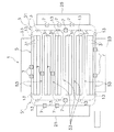
図2及び図3を用いて、自動倉庫3のラック31の構造を説明する。図2は、搬送車システムの斜視図である。図3は、搬送車システムの側面図である。
自動倉庫3は、複数のラック31を有している。各ラック31は、上下左右に並んだ複数の棚33を有する構造であり、それぞれが並列に並べられている。より具体的には、各ラック31は、他のラック31と背中合わせに配置され、一対のラック構造を実現している。そして各対のラック間の通路の上には、天井レール5が配置されている。天井レール5は、複数段の棚33より高い位置にある。
(2) Structure of Rack of Automatic Warehouse The structure of the
The
(3)搬送車
搬送車7は、主に、走行装置15と、昇降台17と、昇降装置19とを有している。走行装置15は、天井レール5を走行するため機構である。昇降台17は、荷物が載置される構造である。この実施形態では、昇降台17には移載装置18が設けられている。
昇降装置19は、走行装置15から昇降台17を吊り下げると共に昇降台17を昇降させるための機構である。昇降装置19は、走行装置15から昇降台17を昇降させるための昇降手段(図示せず)を有している。昇降手段は、例えば、4組の巻き取りドラムであり、巻き取りドラムにはベルト39が巻きかけられている。ベルト39の端部には昇降台17が取り付けられている。図2及び図3に、ベルト39が巻き取りドラムから繰り出されて、昇降台17が荷物と共に下降している状態を示している。
(3) Transport Vehicle The
The lifting
(4)搬送車システムの制御構成
図4を用いて、搬送車システムの制御構成を説明する。図4は、搬送車システムの制御構成を示すブロック図である。
搬送車7は、コントローラ41を有している。コントローラ41は、CPU、RAM、ROM等からなりプログラムを実行するコンピュータである。図4に示すように、コントローラ41は、メモリ43を有している。メモリ43には、昇降可能区間データ及び昇降制限区間データが保存されている。昇降可能区間データは、天井レール5のレイアウトにおける昇降可能区間51の位置を示すデータである。昇降制限区間53は、天井レール5のレイアウトにおける昇降制限区間53の位置を示すデータである。
昇降可能区間51は、ラック31に対応する区間を少なくとも含む。図1に示すように、昇降可能区間51(実線)は、ラック31、入荷エリア21、出荷エリア23、ピッキングエリア25と、それらの前後を含むように設定されている。 また、昇降制限区間53(破線)は、昇降可能区間51以外のエリアに設定されている。
(4) Control Configuration of Carrier System The control configuration of the carrier system will be described with reference to FIG. FIG. 4 is a block diagram showing a control configuration of the carrier system.
The
The
昇降可能区間51とは、昇降装置19が昇降台17を昇降可能になっている区間であり、この区間では昇降台17の高さ位置は制限されない。
昇降制限区間53とは、昇降装置19が昇降台17を昇降することが制限されている区間であり、この区間では昇降台17の高さ位置は制限される。昇降台17は衝突を回避が確実な基準高さ位置(昇降制限区間走行時高さ位置の一例)に配置される。この実施形態では、基準高さ位置は、最上位位置であり、つまり走行装置15に最も接近した位置である。
The elevating
The
各コントローラ41は、上位コントローラ47と交信可能である。上位コントローラ47は、CPU、RAM、ROM等からなりプログラムを実行するコンピュータである。上位コントローラ47は、複数の搬送車7を管理し、これらに走行指令又は搬送指令を割り付ける割り付け機能を有している。なお、「搬送指令」は、走行指令、及び荷つかみ位置と荷おろし位置を含む移載指令を含んでいる。
Each
以上の構成により、コントローラ41が昇降台17を昇降させるのは、昇降可能区間51においてのみである。つまり、コントローラ41は、昇降制限区間53では、走行中に昇降台17を昇降させない。これにより、搬送車システム1の昇降制限区間53において、搬送車7が天井レール5の下方に存在する障害物に衝突しない。
According to the above configuration, the
コントローラ41には、走行装置15、昇降装置19、移載装置18に接続されており、コントローラ41はそれらのモータに駆動信号を送信可能である。
なお、図示していないが、コントローラ41には、各種センサが接続されている。
The
Although not shown, various sensors are connected to the
(5)搬送制御動作
図5及び図6を用いて、コントローラ41による搬送車7の搬送制御動作を説明する。図5は、搬送車システムの制御フローチャートである。図6は、昇降可能区間及び昇降制限区間を走行する搬送車を示す模式図である。
なお、本明細書の制御フローチャートは例示であって、必要に応じて、各ステップの順序を変えたり、各ステップを省略したりしてもよい。また、必要に応じて、複数のステップが同じタイミングで実行されてもよい。
(5) Transport Control Operation The transport control operation of the
Note that the control flowchart in the present specification is an example, and the order of each step may be changed or each step may be omitted as necessary. Also, if necessary, multiple steps may be performed at the same timing.
(5−1)全体制御動作
図5において、ステップS1において、コントローラ41は、上位コントローラ47から搬送指令を受信する。
ステップS2において、コントローラ41は、搬送車7の現在位置が昇降可能区間51であるか否かを判断する。図6の左側の搬送車7のように現在位置が昇降可能区間51であれば(ステップS2でYes)、プロセスはステップS3に移行する。図6の右側の搬送車7のように現在位置が昇降制限区間53であれば(ステップS2でNo)、プロセスはステップS14に移行する。ステップS14では、コントローラ41は、走行装置15に走行を続けさせる。この結果、搬送車7は、昇降制限区間53では昇降台17を基準高さ位置に維持したまま走行し続ける。
(5-1) Overall Control Operation In FIG. 5, the
In step S <b> 2, the
ステップS3では、搬送指令に含まれる目的の棚33が当該昇降可能区間51に存在するか否かを判定する。存在すれば(ステップS3でYes)、プロセスはステップS4に移行する。存在しなければ(ステップS3でNo)、プロセスはステップS8に移行する。
以下に説明するステップS4〜S7は、目的の棚33が当該昇降可能区間51に存在する場合の制御動作である。
In step S3, it is determined whether or not the intended
Steps S <b> 4 to S <b> 7 described below are control operations in the case where the
ステップS4では、コントローラ41は、「走行速度決定1」を実行する。この動作は、図7を用いて後述する。
ステップS5では、コントローラ41は、走行装置15に走行指令(決定された走行速度指令を含む)を送り続け、昇降装置19に昇降指令を送り続ける。その結果、走行装置15が走行しながら、昇降台17は昇降する。
In step S4, the
In step S5, the
ステップS6では、コントローラ41は、昇降台17が目的の棚33に到着したか否かを判断する。到着していれば(ステップS6でYes)、プロセスはステップS7に移行する。到着していなければ、(ステップS6でNo)、プロセスはステップS5に戻る。つまり、目的の棚33に到着するまで、走行装置15が走行し、昇降装置19が昇降台17を昇降する。
ステップS7では、移載装置18が昇降台17と棚33との間で物品を移載する。
In step S6, the
In step S7, the
以下に説明するステップS8〜S12は、目的の棚33が当該昇降可能区間51に存在しない場合の制御動作である。
ステップS8では、コントローラ41は、「走行速度決定2」を実行する。この動作は、図10を用いて後述する。
Steps S <b> 8 to S <b> 12 described below are control operations in the case where the
In step S8, the
ステップS9では、コントローラ41は、走行装置15に走行指令(決定された走行速度指令を含む)を送り続け、昇降装置19に昇降指令を送り続ける。その結果、走行装置15が走行しながら、昇降装置19が昇降台17を昇降させる。
ステップS10では、コントローラ41は、走行装置15が昇降可能区間51の終点に到着したか否かを判断する。到着していれば(ステップS10でYes)、プロセスはステップS11に移行する。到着していなければ、(ステップS10でNo)、プロセスはステップS9に戻る。つまり、走行装置15が昇降可能区間51の終点に到着するまで走行装置15は走行し、昇降装置19は昇降台17を昇降する。
In step S9, the
In step S <b> 10, the
ステップS11では、コントローラ41は、昇降台17が基準高さ位置にあるか否かを判断する。基準高さ位置にあれば(ステップS11でYes)、プロセスはステップS12に移行する。ステップS12では、コントローラ41は、走行装置15に走行を続けさせる。この結果、搬送車7は、昇降台17を基準高さ位置に維持しながら昇降制限区間53を走行し続ける。基準高さ位置になければ(ステップS11でNo)、プロセスはステップS13に移行する。ステップS13では、コントローラ41は、搬送車7を異常停止させる。これにより、昇降制限区間53において、昇降台17が基準高さ位置以外の高さ位置に存在することがない。
In step S11, the
(5−2)走行速度決定1
図7〜図9を用いて、図5のステップS4の走行速度決定1及びその後の搬送車7の動作を説明する。図7は、走行速度決定1を示す制御フローチャートである。図8及び図9は、昇降可能区間内に位置する搬送車が目的の棚まで移動する際の位置関係を示す模式図である。なお、「走行速度を決定する」とは、加速・一定速・減速を含む走行速度パターンを決定することを意味する。
図7において、ステップS21では、コントローラ41は、走行装置15における目的の棚33までの走行移動時間を算出する。走行移動時間は、現在位置と目的の棚33との走行方向距離(例えば、L1、L2)とそれに対応する基準走行速度パターンV1ref(例えば、最大走行速度パターンV1max)から算出される。なお、「走行速度パターン」は、例えば、加減速、一定速の情報を含んでいる。
(5-2)
The
In FIG. 7, in step S <b> 21, the
ステップS22では、コントローラ41は、昇降装置19における目的の棚33までの昇降移動時間を算出する。昇降移動時間は、現在位置と目的の棚33との昇降方向距離(例えば、H1、H2)とそれに対応する基準昇降速度パターンV2ref(例えば、最大昇降速度パターンV2max)から算出される。なお、「昇降速度パターン」は、例えば、加減速、一定速の情報を含んでいる。
ステップS23では、コントローラ41は、昇降移動時間が走行移動時間より長いか否かを判断する。長ければ(ステップS23でYes)、プロセスはステップS25に移行する。長くなければ(ステップS23でNo)、プロセスはステップS24に移行する。
In step S22, the
In step S23, the
ステップS24では、コントローラ41は、走行速度パターンを基準走行速度パターンV1refに設定する。この場合、昇降台17は、走行装置15が目的の棚33の走行方向位置に到着するまでに、目的の棚33の昇降方向位置にすでに到着している。
ステップS25では、コントローラ41は、走行時間が昇降時間と等しくなるように走行速度パターンを設定する。この場合、昇降台17は、走行装置15が目的の棚33の走行方向位置に到着すると同時に、目的の棚33の昇降方向位置に到着する。
In step S24, the
In step S25, the
以上に説明したように、昇降台17が昇降制限区間53にある状態から、昇降可能区間51における目的の棚33に向けて昇降台17を移動させる動作を行うに当たって、コントローラ41は、昇降台17の基準高さ位置から目的の棚33までの下降量と、昇降可能区間51の始点と目的の棚33までの走行方向距離とを考慮して、走行装置15の始点から目的の棚33までの走行速度パターンを決定している。
具体的には、コントローラ41が、例えば、下降量から基準昇降時間を算出し、さらに走行方向距離から基準走行時間を算出する。次に、基準昇降時間が基準走行時間より長い場合には、コントローラ41は走行時間を基準走行時間より長く設定し、具体的には基準昇降時間とほぼ同じ又は長く設定する。そして、コントローラ41は、設定された走行時間と走行方向移動距離に基づいて、走行速度(すなわち、走行速度パターン)を決定する。これにより、走行装置15が昇降可能区間51を走行している間に昇降台17は下降を続け、そして走行方向の目的の棚33の位置では、昇降台17はすでに目的の棚33の高さ位置まで移動している。
さらに具体的には、図8及び図9に示すように、走行装置15が走行しながら、昇降台17は昇降する。なお、図8は、昇降台17が棚33から棚33に移動する動作を示している。また、図9は、昇降台17が昇降制限区間53から昇降可能区間51に進入し、その後に目的の棚33に移動する動作を示している。
As described above, the
Specifically, for example, the
More specifically, as shown in FIG. 8 and FIG. 9, the
その結果、搬送車7が昇降可能区間51において目的の棚33の位置まで移動する際に、昇降台17の昇降を待つために走行装置15が停止することがない。この結果、搬送車システム1の搬送能力が向上する。これは、目的の棚33に対応する位置での搬送車7の停止時間を短くできることで、複数の搬送車7による渋滞の可能性を減らせるからである。
また、搬送車7がより低速で目的の棚33に接近するので、停止時の昇降台17の揺れを減らせる。
As a result, when the
In addition, since the
(5−3)走行速度決定2
図10及び図11を用いて、図5のステップS8の走行速度決定2及びその後の搬送車7の動作を説明する。図10は、走行速度決定2を示す制御フローチャートである。図11は、走行可能区間の終点まで昇降台が移動する際の位置関係を示す模式図である。
図10において、ステップS31では、コントローラ41は、昇降台17が基準高さ位置にあるか否かを判断する。基準高さ位置であれば(ステップS31でYes)、プロセスはステップS24に移行し、そこで走行速度パターンを基準走行速度パターンV1refに設定する。基準高さ位置でなければ(ステップS31でNo)、プロセスはステップS32に移行する。
(5-3)
The
In FIG. 10, in step S31, the
ステップS32では、コントローラ41は、走行装置15における昇降可能区間51の終点までの走行移動時間を算出する。走行移動時間は、現在位置と終点との走行方向距離(例えば、L3)とそれに対応する基準走行速度パターンV1ref(例えば、最大走行速度パターンV1max)から算出される。
ステップS33では、コントローラ41は、昇降装置19における基準高さ位置までの昇降移動時間を算出する。昇降移動時間は、現在位置と終点との昇降方向距離(H3)と基準昇降速度パターンV2ref(例えば、最大昇降速度パターンV2max)から算出される。
ステップS23では、コントローラ41は、昇降移動時間が走行移動時間より長いか否かを判断する。長ければ(ステップS23でYes)、プロセスはステップS25に移行する。長くなければ(ステップS23でNo)、プロセスはステップS24に移行する。
In step S <b> 32, the
In step S33, the
In step S23, the
ステップS24では、コントローラ41は、走行速度を基準走行速度パターンV1refに設定する。この場合、昇降台17は、走行装置15が終点の走行方向位置に到着するまでに、基準高さ位置に到着している。
ステップS25では、コントローラ41は、走行時間が昇降時間と等しくなるように走行速度パターンを設定する。この場合、昇降台17は、走行装置15が終点の走行方向位置に到着すると同時に、基準高さ位置に到着する。つまり、搬送車7は、終点で停止することなく、昇降制限区間53に進入可能である。
In step S24, the
In step S25, the
以上に述べたように、昇降台17が昇降可能区間51にある状態から、昇降制限区間53に向かって走行装置15が走行開始する際に、コントローラ41は、昇降台17の高さ位置から基準高さ位置(昇降制限区間走行時高さ位置の一例)までの上昇量と、走行装置15の走行方向停止位置から昇降可能区間51の終点までの走行方向距離とを考慮して、終点までの走行装置15の走行速度を決定している。
具体的には、コントローラ41が、例えば、上昇量から基準昇降時間を算出し、さらに走行方向距離から基準走行時間を算出する。次に、基準昇降時間が基準走行時間より長い場合には、コントローラ41は走行時間を基準走行時間より長く設定し、具体的には基準昇降時間とほぼ同じ又は長く設定する。そして、コントローラ41は、設定された走行時間と走行方向移動距離に基づいて、走行速度(すなわち、走行速度パターン)を決定する。
これにより、図11に示すように、走行装置15が昇降可能区間51を走行している間に昇降台17は上昇を続け、そして昇降可能区間51の終点では、昇降台17はすでに基準高さ位置まで移動している。その結果、搬送車7が昇降可能区間51から昇降制限区間53に移行する際に、搬送車7が停止することなく走行を続ける。この結果、搬送車システム1の搬送能力が向上する。
As described above, when the traveling
Specifically, for example, the
Thus, as shown in FIG. 11, the
2.実施形態の特徴
搬送車システム1(搬送車システムの一例)は、ラック31(ラックの一例)と、天井レール5(軌道の一例)と、搬送車7(搬送車の一例)とを有している。
ラック31は、複数段の棚33を有する。
天井レール5は、複数段の棚33より高い位置において、ラック31に沿って設けられている。
2. Characteristics of the embodiment The carrier system 1 (an example of a carrier system) includes a rack 31 (an example of a rack), a ceiling rail 5 (an example of a track), and a carrier 7 (an example of a carrier) There is.
The
The
搬送車7は、天井レール5を走行する走行装置15と、荷物を保持する昇降台17と、走行装置15から昇降台17を吊り下げると共に昇降台17を昇降させる昇降装置19と、天井レール5においてラック31に対応する区間を少なくとも含む昇降可能区間51と、昇降制限区間53とを記憶しており、昇降可能区間51においてのみ昇降装置19によって昇降台17を昇降させるコントローラ41と、を有する。
なお、ルート全体を記憶し、さらに昇降可能区間または昇降制限区間の一方を記憶している状態は、昇降可能区間と昇降制限区間とを記憶すると言える。
The
A state in which the entire route is stored and one of the elevating section and the elevating restriction section is stored can be said to store the elevating section and the elevating restriction section.
搬送車システムでは、コントローラ41が、昇降可能区間51においてのみ昇降装置19によって昇降台17を昇降させる。つまり、コントローラ41は、昇降制限区間53では昇降台17を昇降させない。これにより、搬送車システム1において、搬送車7が天井レール5の下方に存在する障害物に衝突しない。
In the carrier system, the
3.他の実施形態
以上、本発明の一実施形態について説明したが、本発明は上記実施形態に限定されるものではなく、発明の要旨を逸脱しない範囲で種々の変更が可能である。特に、本明細書に書かれた複数の実施形態及び変形例は必要に応じて任意に組み合せ可能である。
(1)前記実施形態では、昇降可能区間はラックの始点と終点との間に規定されていたが、昇降可能区間は少なくともラックに対応する区間を含んでいればよいので、前記実施形態には限定されない。例えば、ラックの始点又は終点のさらに外側まで昇降可能区間が設けられていてもよい。
(2)前記実施形態では荷物は昇降台の上に置かれていたが、荷物は昇降台に保持されていればよいので、前記実施形態には限定されない。例えば、昇降台が荷物を把持する構造を有していてもよい。
3. Other Embodiments Although one embodiment of the present invention has been described above, the present invention is not limited to the above embodiment, and various modifications can be made without departing from the scope of the invention. In particular, the embodiments and modifications described herein may be arbitrarily combined as needed.
(1) In the embodiment, the elevating section is defined between the start point and the end point of the rack, but the elevating section only needs to include at least a section corresponding to the rack. It is not limited. For example, the elevating section may be provided to the outside of the start point or the end point of the rack.
(2) Although the package is placed on the elevator platform in the above embodiment, the package is not limited to the above embodiment as long as the package is held by the elevator platform. For example, the elevator may have a structure for gripping a load.
(3)前記実施形態では移載装置が昇降台に搭載されていたが、昇降台と棚との間で荷物が移載可能であればよいので、前記実施形態には限定されない。例えば、移載装置は棚に設けられていてもよい。
(4)前記実施形態では昇降制限区間における昇降台の基準高さ位置は最上位位置であったが、昇降台が下方の障害物に衝突しなければよいので、前記実施形態に限定されない。例えば、基準高さ位置は最上位位置より下方の上位位置であってもよい。
(3) Although the transfer device is mounted on the elevating table in the above embodiment, it is not limited to the above embodiment because it is only necessary to transfer the load between the elevating table and the shelf. For example, the transfer device may be provided on a shelf.
(4) Although the reference height position of the elevator platform in the elevation restricted section is the highest position in the embodiment, the elevator platform is not limited to the above embodiment because it does not have to collide with the obstacle located below. For example, the reference height position may be an upper position below the top position.
(5)前記実施形態では昇降制限区間における昇降台の基準高さ位置は一定であったが、昇降台が下方の障害物に衝突しなければよいので、前記実施形態に限定されない。例えば、基準高さ位置は昇降制限区間によって異なるように設定されてもよい。
(6)前記実施形態では走行装置の走行速度の調整を行ったが、昇降装置による昇降台の昇降速度の調整も行ってよい。
(5) Although the reference height position of the elevator platform in the elevation restricted section is constant in the embodiment, the elevator platform is not limited to the embodiment because it is not necessary to collide with the obstacle located below. For example, the reference height position may be set to be different depending on the elevation restriction section.
(6) Although the travel speed of the travel device is adjusted in the embodiment, the elevation speed of the elevator platform may be adjusted by the elevator device.
本発明は、複数段の棚を有するラックと、複数段の棚より高い位置においてラックに沿って設けられた軌道と、軌道に沿って走行するともに昇降台を昇降させる搬送車とを有する搬送車システムに広く適用される。 The present invention provides a carriage having a rack having a plurality of racks, a track provided along the rack at a position higher than the plurality of racks, and a carrier that travels along the track and raises and lowers the elevator platform. Widely applied to the system.
1 :搬送車システム
3 :自動倉庫
5 :天井レール
7 :搬送車
9 :支柱
11 :天井
13 :分岐合流部
15 :走行装置
18 :移載装置
17 :昇降台
19 :昇降装置
21 :入荷エリア
23 :出荷エリア
25 :ピッキングエリア
31 :ラック
33 :棚
39 :ベルト
41 :コントローラ
43 :メモリ
47 :上位コントローラ
51 :昇降可能区間
53 :昇降制限区間
DESCRIPTION OF SYMBOLS 1: Carrier vehicle system 3: Automatic warehouse 5: Ceiling rail 7: Carrier 9: Support pillar 11: Ceiling 13: Branching junction part 15: Traveling device 18: Transfer device 17: Lifting platform 19: Lifting device 19: Lifting device 21: Receiving area 23 : Shipping area 25: Picking area 31: Rack 33: Shelf 39: Belt 41: Controller 43: Memory 47: Upper controller 51: Liftable section 53: Lifting restricted section
Claims (3)
前記複数段の棚より高い位置において、前記ラックに沿って設けられた軌道と、
前記軌道を走行する走行装置と、荷物を保持する昇降台と、前記走行装置から前記昇降台を吊り下げると共に前記昇降台を昇降させる昇降装置と、前記軌道において前記ラックに対応する区間を少なくとも含む昇降可能区間と、昇降制限区間とを記憶しており、前記昇降可能区間においてのみ前記昇降装置によって前記昇降台を昇降させるコントローラと、を有する搬送車と、
を備えた搬送車システム。 A rack with multiple tiers of shelves,
A track provided along the rack at a position higher than the plurality of shelves;
The traveling device for traveling on the track, a lifting platform for holding a load, a lifting device for suspending the lifting platform and lifting the lifting platform from the travel device, and at least a section corresponding to the rack in the track A transport vehicle storing a elevating section and a elevating restricted section, and having a controller for elevating the elevating table by the elevating device only in the elevating section;
Carrier system equipped with
Priority Applications (1)
| Application Number | Priority Date | Filing Date | Title |
|---|---|---|---|
| JP2015066959A JP6424705B2 (en) | 2015-03-27 | 2015-03-27 | Carrier system |
Applications Claiming Priority (1)
| Application Number | Priority Date | Filing Date | Title |
|---|---|---|---|
| JP2015066959A JP6424705B2 (en) | 2015-03-27 | 2015-03-27 | Carrier system |
Publications (2)
| Publication Number | Publication Date |
|---|---|
| JP2016185862A JP2016185862A (en) | 2016-10-27 |
| JP6424705B2 true JP6424705B2 (en) | 2018-11-21 |
Family
ID=57202416
Family Applications (1)
| Application Number | Title | Priority Date | Filing Date |
|---|---|---|---|
| JP2015066959A Active JP6424705B2 (en) | 2015-03-27 | 2015-03-27 | Carrier system |
Country Status (1)
| Country | Link |
|---|---|
| JP (1) | JP6424705B2 (en) |
Families Citing this family (1)
| Publication number | Priority date | Publication date | Assignee | Title |
|---|---|---|---|---|
| KR102651030B1 (en) * | 2021-06-08 | 2024-03-26 | 세메스 주식회사 | Transfering unit, article transferring system and controlling method of transfering unit |
Family Cites Families (6)
| Publication number | Priority date | Publication date | Assignee | Title |
|---|---|---|---|---|
| JPS63242809A (en) * | 1987-03-27 | 1988-10-07 | Murata Mach Ltd | Article storage |
| JP2906308B2 (en) * | 1992-10-28 | 1999-06-21 | 株式会社岡村製作所 | Method and apparatus for controlling traveling of stacker crane and lifting and lowering of cargo bed |
| JP2004210454A (en) * | 2002-12-27 | 2004-07-29 | Ishikawajima Harima Heavy Ind Co Ltd | Crane control device and crane control program |
| JP4123383B2 (en) * | 2004-08-12 | 2008-07-23 | 村田機械株式会社 | Overhead traveling vehicle system |
| JP2008235067A (en) * | 2007-03-22 | 2008-10-02 | Toshiba Lighting & Technology Corp | Baton device and lighting device |
| WO2013182676A1 (en) * | 2012-06-07 | 2013-12-12 | Jaguar Land Rover Limited | Crane and related method of operation |
-
2015
- 2015-03-27 JP JP2015066959A patent/JP6424705B2/en active Active
Also Published As
| Publication number | Publication date |
|---|---|
| JP2016185862A (en) | 2016-10-27 |
Similar Documents
| Publication | Publication Date | Title |
|---|---|---|
| JP6315098B2 (en) | Sorting system and sorting method | |
| JP4666213B2 (en) | Goods storage equipment | |
| JP5418503B2 (en) | Automatic warehouse | |
| JP4586990B2 (en) | Goods storage equipment | |
| EP2860136B1 (en) | Conveyance system and temporary storage method of articles in conveyance system | |
| JP4756371B2 (en) | Goods storage equipment | |
| US11084655B2 (en) | Vehicle for moving a container and system allowing such vehicle to move the container | |
| JP2016050090A (en) | Conveyance vehicle system and method for controlling the conveyance vehicle system | |
| JP4273423B2 (en) | Transport device | |
| JP6627677B2 (en) | Goods storage equipment | |
| JPH0672512A (en) | Control method for automatic warehouse | |
| JP6424705B2 (en) | Carrier system | |
| JP5572104B2 (en) | Mobile system | |
| WO2011070869A1 (en) | Mobile body system | |
| JP4666224B2 (en) | Goods transport equipment | |
| JP5487218B2 (en) | Automatic warehouse | |
| JP7472538B2 (en) | Conveyor | |
| JP4203825B2 (en) | Article conveying device | |
| JP2006143363A (en) | Article storage facility | |
| JPH06156621A (en) | Automatic warehouse | |
| JPH0656225A (en) | Control method of automated warehouse | |
| JPH069013A (en) | Carry-out control method for automated warehouse | |
| JPH069012A (en) | Carry-out control method for automated warehouse | |
| JPH0672502A (en) | Control method for automatic warehouse | |
| JPH069011A (en) | Carry-out control method for automated warehouse |
Legal Events
| Date | Code | Title | Description |
|---|---|---|---|
| A621 | Written request for application examination |
Free format text: JAPANESE INTERMEDIATE CODE: A621 Effective date: 20171220 |
|
| A977 | Report on retrieval |
Free format text: JAPANESE INTERMEDIATE CODE: A971007 Effective date: 20180914 |
|
| TRDD | Decision of grant or rejection written | ||
| A01 | Written decision to grant a patent or to grant a registration (utility model) |
Free format text: JAPANESE INTERMEDIATE CODE: A01 Effective date: 20180925 |
|
| A61 | First payment of annual fees (during grant procedure) |
Free format text: JAPANESE INTERMEDIATE CODE: A61 Effective date: 20181008 |
|
| R150 | Certificate of patent or registration of utility model |
Ref document number: 6424705 Country of ref document: JP Free format text: JAPANESE INTERMEDIATE CODE: R150 |
|
| R250 | Receipt of annual fees |
Free format text: JAPANESE INTERMEDIATE CODE: R250 |
|
| R250 | Receipt of annual fees |
Free format text: JAPANESE INTERMEDIATE CODE: R250 |
|
| R250 | Receipt of annual fees |
Free format text: JAPANESE INTERMEDIATE CODE: R250 |