JP6423080B2 - Tangential milling insert and multi-blade milling - Google Patents
Tangential milling insert and multi-blade milling Download PDFInfo
- Publication number
- JP6423080B2 JP6423080B2 JP2017507873A JP2017507873A JP6423080B2 JP 6423080 B2 JP6423080 B2 JP 6423080B2 JP 2017507873 A JP2017507873 A JP 2017507873A JP 2017507873 A JP2017507873 A JP 2017507873A JP 6423080 B2 JP6423080 B2 JP 6423080B2
- Authority
- JP
- Japan
- Prior art keywords
- cutter
- insert
- base
- positioning structure
- tangential
- Prior art date
- Legal status (The legal status is an assumption and is not a legal conclusion. Google has not performed a legal analysis and makes no representation as to the accuracy of the status listed.)
- Active
Links
- 238000003801 milling Methods 0.000 title claims description 124
- 238000010586 diagram Methods 0.000 description 10
- 239000002826 coolant Substances 0.000 description 6
- 239000000463 material Substances 0.000 description 6
- 238000003754 machining Methods 0.000 description 5
- 239000007921 spray Substances 0.000 description 4
- 229910000838 Al alloy Inorganic materials 0.000 description 2
- 229910000851 Alloy steel Inorganic materials 0.000 description 1
- 229910052582 BN Inorganic materials 0.000 description 1
- PZNSFCLAULLKQX-UHFFFAOYSA-N Boron nitride Chemical compound N#B PZNSFCLAULLKQX-UHFFFAOYSA-N 0.000 description 1
- 229910000831 Steel Inorganic materials 0.000 description 1
- 229910001069 Ti alloy Inorganic materials 0.000 description 1
- 229910052796 boron Inorganic materials 0.000 description 1
- 229910003460 diamond Inorganic materials 0.000 description 1
- 239000010432 diamond Substances 0.000 description 1
- 230000005484 gravity Effects 0.000 description 1
- 229910001234 light alloy Inorganic materials 0.000 description 1
- 238000000465 moulding Methods 0.000 description 1
- 230000002093 peripheral effect Effects 0.000 description 1
- 239000010959 steel Substances 0.000 description 1
Images


Classifications
-
- B—PERFORMING OPERATIONS; TRANSPORTING
- B23—MACHINE TOOLS; METAL-WORKING NOT OTHERWISE PROVIDED FOR
- B23C—MILLING
- B23C5/00—Milling-cutters
- B23C5/02—Milling-cutters characterised by the shape of the cutter
- B23C5/08—Disc-type cutters
-
- B—PERFORMING OPERATIONS; TRANSPORTING
- B23—MACHINE TOOLS; METAL-WORKING NOT OTHERWISE PROVIDED FOR
- B23C—MILLING
- B23C5/00—Milling-cutters
- B23C5/006—Details of the milling cutter body
-
- B—PERFORMING OPERATIONS; TRANSPORTING
- B23—MACHINE TOOLS; METAL-WORKING NOT OTHERWISE PROVIDED FOR
- B23C—MILLING
- B23C5/00—Milling-cutters
- B23C5/02—Milling-cutters characterised by the shape of the cutter
- B23C5/06—Face-milling cutters, i.e. having only or primarily a substantially flat cutting surface
-
- B—PERFORMING OPERATIONS; TRANSPORTING
- B23—MACHINE TOOLS; METAL-WORKING NOT OTHERWISE PROVIDED FOR
- B23C—MILLING
- B23C5/00—Milling-cutters
- B23C5/16—Milling-cutters characterised by physical features other than shape
- B23C5/20—Milling-cutters characterised by physical features other than shape with removable cutter bits or teeth or cutting inserts
- B23C5/22—Securing arrangements for bits or teeth or cutting inserts
- B23C5/2204—Securing arrangements for bits or teeth or cutting inserts with cutting inserts clamped against the walls of the recess in the cutter body by a clamping member acting upon the wall of a hole in the insert
- B23C5/2208—Securing arrangements for bits or teeth or cutting inserts with cutting inserts clamped against the walls of the recess in the cutter body by a clamping member acting upon the wall of a hole in the insert for plate-like cutting inserts
- B23C5/2213—Securing arrangements for bits or teeth or cutting inserts with cutting inserts clamped against the walls of the recess in the cutter body by a clamping member acting upon the wall of a hole in the insert for plate-like cutting inserts having a special shape
-
- B—PERFORMING OPERATIONS; TRANSPORTING
- B23—MACHINE TOOLS; METAL-WORKING NOT OTHERWISE PROVIDED FOR
- B23C—MILLING
- B23C5/00—Milling-cutters
- B23C5/16—Milling-cutters characterised by physical features other than shape
- B23C5/20—Milling-cutters characterised by physical features other than shape with removable cutter bits or teeth or cutting inserts
- B23C5/22—Securing arrangements for bits or teeth or cutting inserts
- B23C5/2204—Securing arrangements for bits or teeth or cutting inserts with cutting inserts clamped against the walls of the recess in the cutter body by a clamping member acting upon the wall of a hole in the insert
- B23C5/2234—Securing arrangements for bits or teeth or cutting inserts with cutting inserts clamped against the walls of the recess in the cutter body by a clamping member acting upon the wall of a hole in the insert for plate-like cutting inserts fitted on a ring or ring segment
-
- B—PERFORMING OPERATIONS; TRANSPORTING
- B23—MACHINE TOOLS; METAL-WORKING NOT OTHERWISE PROVIDED FOR
- B23C—MILLING
- B23C5/00—Milling-cutters
- B23C5/28—Features relating to lubricating or cooling
-
- B—PERFORMING OPERATIONS; TRANSPORTING
- B23—MACHINE TOOLS; METAL-WORKING NOT OTHERWISE PROVIDED FOR
- B23C—MILLING
- B23C2200/00—Details of milling cutting inserts
- B23C2200/04—Overall shape
- B23C2200/0433—Parallelogram
-
- B—PERFORMING OPERATIONS; TRANSPORTING
- B23—MACHINE TOOLS; METAL-WORKING NOT OTHERWISE PROVIDED FOR
- B23C—MILLING
- B23C2200/00—Details of milling cutting inserts
- B23C2200/12—Side or flank surfaces
- B23C2200/125—Side or flank surfaces discontinuous
-
- B—PERFORMING OPERATIONS; TRANSPORTING
- B23—MACHINE TOOLS; METAL-WORKING NOT OTHERWISE PROVIDED FOR
- B23C—MILLING
- B23C2200/00—Details of milling cutting inserts
- B23C2200/36—Other features of the milling insert not covered by B23C2200/04 - B23C2200/32
-
- B—PERFORMING OPERATIONS; TRANSPORTING
- B23—MACHINE TOOLS; METAL-WORKING NOT OTHERWISE PROVIDED FOR
- B23C—MILLING
- B23C2200/00—Details of milling cutting inserts
- B23C2200/36—Other features of the milling insert not covered by B23C2200/04 - B23C2200/32
- B23C2200/367—Mounted tangentially, i.e. where the rake face is not the face with largest area
-
- B—PERFORMING OPERATIONS; TRANSPORTING
- B23—MACHINE TOOLS; METAL-WORKING NOT OTHERWISE PROVIDED FOR
- B23C—MILLING
- B23C2210/00—Details of milling cutters
- B23C2210/16—Fixation of inserts or cutting bits in the tool
- B23C2210/168—Seats for cutting inserts, supports for replacable cutting bits
-
- B—PERFORMING OPERATIONS; TRANSPORTING
- B23—MACHINE TOOLS; METAL-WORKING NOT OTHERWISE PROVIDED FOR
- B23C—MILLING
- B23C2210/00—Details of milling cutters
- B23C2210/24—Overall form of the milling cutter
- B23C2210/244—Milling cutters comprised of disc-shaped modules or multiple disc-like cutters
-
- B—PERFORMING OPERATIONS; TRANSPORTING
- B23—MACHINE TOOLS; METAL-WORKING NOT OTHERWISE PROVIDED FOR
- B23C—MILLING
- B23C2250/00—Compensating adverse effects during milling
- B23C2250/04—Balancing the cutter
Landscapes
- Engineering & Computer Science (AREA)
- Mechanical Engineering (AREA)
- Milling Processes (AREA)
Description
関連出願の相互参照
本出願は、2015年8月10日に出願された「タンジェンシャル型フライスインサート」と題する中国出願第201520599136.9号、および2015年8月10日に出願された「マルチ刃フライス」と題する中国出願第201520599364.6号に基づく利益を主張し、これらの出願の全体が参照され本明細書に組み込まれる。
Cross-reference of related applications This application includes Chinese application No. 201520599136.9 entitled “ Tangential Milling Insert” filed on August 10, 2015, and “Multi-blade” filed on August 10, 2015. Claims benefit based on Chinese application No. 201520599364.6 entitled “Milling”, the entirety of these applications being referenced and incorporated herein.
本発明は、超硬工具の技術分野に関し、特に、タンジェンシャル型フライスインサート及びタンジェンシャル型フライスインサートを用いたマルチ刃フライスに関する。 The present invention relates to the technical field of carbide tools, and more particularly, to a tangential milling insert and a multi-blade milling using the tangential milling insert.
フライスは、1つまたは複数のフライスインサートを備えたロータリーカッターであり、各フライスインサートを介して断続的に加工物を切断することによって、フライス盤上の平坦面、ステージ、及び溝を加工し、表面を成型するなど、機械加工するために主に使用される。フライスのカッターホイールベースをリサイクルするために、既存のフライスは、しばしばフライスインサートとフライスとの組み合わせ構造を採用する。 A milling cutter is a rotary cutter with one or more milling inserts that cuts the workpiece intermittently through each milling insert to machine flat surfaces, stages, and grooves on the milling machine, Mainly used for machining, such as molding. In order to recycle the milling cutter wheelbase, existing mills often employ a combination of milling insert and milling.
現在のフライスインサートは、大抵単一のチップデザインを使用する。なぜなら、現在のフライスインサートは、通常、クランプ位置決めモードを使用し、カッターチップが固定部分に設計されている場合、固定された部位が摩耗する可能性があり、フライスの作業信頼性に影響を与える可能性があるからである。 Current milling inserts often use a single chip design. Because current milling inserts usually use clamp positioning mode and if the cutter tip is designed to a fixed part, the fixed part may wear out, affecting the working reliability of the milling cutter Because there is a possibility.
フライスが、フライス盤の主軸に取り付けられた後、主軸は作動する。フライスホイールの回転により、フライスの外輪に取り付けられたフライスインサートは、フライス加工および機械加工作業を行うことができる。従来のフライスベースは、通常、単一の構造(例えば、アルミニウム合金構造)を採用し、長い加工時間および高い動作周波数の場合に、位置決め不良または機械加工ずれなどの問題が発生する傾向があり、緊急に安定性を改善する必要がある。また、位置決め構造がクランプ位置決めモードを採用することが多いため、信頼性が保証されていることを前提として、搭載可能なフライスインサートの数をさらに増やすことができず、さらなる加工効率の向上には限界がある。 After the milling machine is attached to the main spindle of the milling machine, the main spindle operates. Due to the rotation of the milling wheel, the milling insert attached to the outer ring of the milling can perform milling and machining operations. Conventional milling bases typically employ a single structure (eg, an aluminum alloy structure) and tend to experience problems such as misalignment or machining misalignment at long processing times and high operating frequencies, There is an urgent need to improve stability. In addition, since the positioning structure often adopts the clamp positioning mode, the number of milling inserts that can be mounted cannot be further increased on the premise that reliability is guaranteed. There is a limit.
上記の問題に鑑みて、本発明は、新しいタンジェンシャル型フライスインサートとマルチ刃フライスを提供する。 In view of the above problems, the present invention provides a new tangential milling insert and multi-blade milling.
本発明は、タンジェンシャル型フライスインサートであって、インサートベースとカッターチップユニットとを備え、インサートベースには、タンジェンシャル型フライスインサートをフライスホイールに取り付けるための取り付け穴が設けられ、カッターチップユニットは、インサートベースに取り付けられ、カッターチップユニットは、ダブルカッターチップ構造を有する。 The present invention is a tangential milling insert comprising an insert base and a cutter tip unit, the insert base being provided with mounting holes for attaching the tangential milling insert to a milling wheel, The cutter tip unit is attached to the insert base and has a double cutter tip structure.
選択的に、ダブルカッターチップ構造は、第1カッターチップ及び第2カッターチップを含み、インサートベースの断面は、取り付け穴の軸線に垂直な4つの頂点を有し、第1カッターチップ及び第2カッターチップは、互いに対応する位置でインサートベース上の2つの頂点上に配置される。 Optionally, the double cutter tip structure includes a first cutter tip and a second cutter tip, the insert base cross-section has four vertices perpendicular to the axis of the mounting hole, and the first cutter tip and the second cutter The chips are arranged on two vertices on the insert base at positions corresponding to each other.
選択的に、インサートベースは、第1側面と、第1側面に対向する第2側面と、を有し、第1側面には、第1カッターチップ支持面と第1位置決め構造が設けられ、第1位置決め構造は、第1カッターチップ支持面に対してインサートベースの内側に凹んでおり、第2側面には、第2カッターチップ支持面と第2位置決め構造が設けられ、第2位置決め構造は、第2カッターチップ支持面に対してインサートベースの内側に凹んでいる。 Optionally, the insert base has a first side surface and a second side surface facing the first side surface, and the first side surface is provided with a first cutter tip support surface and a first positioning structure, The first positioning structure is recessed inside the insert base with respect to the first cutter tip support surface, and the second side surface is provided with a second cutter tip support surface and a second positioning structure. It is recessed inside the insert base with respect to the second cutter tip support surface.
選択的に、第1位置決め構造及び第2位置決め構造は、両方とも曲げられた平面構造を有する。 Optionally, the first positioning structure and the second positioning structure both have a bent planar structure.
選択的に、曲げられた平面構造は、第1面及び第2面を含み、第2面は、第1面に対してインサートベースの内側に傾斜している。 Optionally, the bent planar structure includes a first surface and a second surface , the second surface being inclined inward of the insert base relative to the first surface .
選択的に、第1面は、第1平坦面及び第1曲面を有し、第1位置決め構造における第1曲面は、第1カッターチップ支持面と、第1位置決め構造における第1平坦面と、の間に位置し、第2位置決め構造における第1曲面は、第2カッターチップ支持面と、第2位置決め構造における第1平坦面との間に位置し、第2面は、第2平坦面及び第2曲面を有し、第1位置決め構造における第2曲面は、第1カッターチップ支持面と、第1位置決め構造における第2平坦面と、の間に位置し、第2位置決め構造における第2曲面は、第2カッターチップ支持面と、第2位置決め構造における第2平坦面とで接続される。 Optionally, the first surface has a first flat surface and a first curved surface, the first curved surface in the first positioning structure is a first cutter tip support surface, a first flat surface in the first positioning structure, The first curved surface in the second positioning structure is located between the second cutter tip support surface and the first flat surface in the second positioning structure, and the second surface is the second flat surface and The second curved surface having the second curved surface is located between the first cutter tip support surface and the second flat surface in the first positioning structure, and the second curved surface in the second positioning structure. Are connected by the second cutter tip support surface and the second flat surface in the second positioning structure.
選択的に、第2曲面は、取り付け穴の軸線と平行な軸線を有する円錐面である。 Optionally, the second curved surface is a conical surface having an axis parallel to the axis of the mounting hole.
選択的に、第1面の幅は、ベースの厚さの1/3〜1/2、及び/又は第2面と第1面との間の角度が10°〜30°である。 Optionally, the width of the first surface is 1/3 to 1/2 of the thickness of the base and / or the angle between the second surface and the first surface is 10 ° to 30 °.
本発明は、カッターホイールベースと、ネジアセンブリと、タンジェンシャル型フライスインサートと、を含み、カッターホイールベースは、第1カッターベース及び第2カッターベースを含み、第1カッターベースは、第2カッターベースと、第2カッターベースに設けられたタンジェンシャル型フライスインサートと、に接続される。 The present invention includes a cutter wheel base, a screw assembly, and a tangential milling insert. The cutter wheel base includes a first cutter base and a second cutter base, and the first cutter base is a second cutter base. And a tangential milling insert provided in the second cutter base.
ネジアセンブリは、ダイナミックバランス調整ネジと、取り付け及び位置決めネジセットと、を含み、ダイナミックバランス調整ネジは、第1カッターベースに設けられ、タンジェンシャル型フライスインサートは、取り付け及び位置決めネジセットを介して、第2カッターベースに接続される。 The screw assembly includes a dynamic balance adjustment screw and an attachment and positioning screw set, the dynamic balance adjustment screw is provided on the first cutter base, and the tangential milling insert is inserted through the attachment and positioning screw set. Connected to the second cutter base.
第2カッターベースは、タンジェンシャル型フライスインサートを取り付けるためのインサート取り付け溝と、インサート取り付け溝の底面に設けられた第1ネジ穴と、インサート取り付け溝に連通する交互の溝と、を含み、 The second cutter base includes an insert mounting groove for mounting the tangential milling insert, a first screw hole provided in the bottom surface of the insert mounting groove, and alternate grooves communicating with the insert mounting groove.
タンジェンシャル型インサートは、インサート取り付け溝に装着されると、未使用のカッターチップ構造が退避溝内に配置され、位置決め構造は、インサート取り付け溝の側方に位置する第1位置決め平面と、インサート取り付け溝の側面に取り付けられた第2固定ネジとを含み、カッターホイールベースは、第2固定ネジに適合する第2ネジ穴を含み、第2ネジ穴の軸線は第1ネジ穴の軸線と平行である。 When the tangential type insert is mounted in the insert mounting groove, an unused cutter tip structure is disposed in the retraction groove, and the positioning structure includes a first positioning plane located on the side of the insert mounting groove, and the insert mounting. A second fixing screw attached to a side surface of the groove, the cutter wheel base includes a second screw hole that fits the second fixing screw, and the axis of the second screw hole is parallel to the axis of the first screw hole. is there.
本発明は、カッターホイールベースと、ネジアセンブリと、タンジェンシャル型フライスインサートとを備え、カッターホイールベースは、第1カッターベースと第2カッターベースを含み、第1カッターベースは、第2カッターベースに接続され、タンジェンシャル型フライスインサートは、第2カッターベースに接続され、 The present invention includes a cutter wheel base, a screw assembly, and a tangential type milling insert. The cutter wheel base includes a first cutter base and a second cutter base, and the first cutter base is a second cutter base. Connected, the tangential milling insert is connected to the second cutter base,
ネジアセンブリは、ダイナミックバランス調整ネジと、取り付け及び位置決めネジセットと、を含み、ダイナミックバランス調整ネジは、第1カッターベースに設けられ、タンジェンシャル型フライスインサートは、取り付け及び位置決めネジセットを介して第2カッターベースに接続されるマルチ刃フライスを提供する。 The screw assembly includes a dynamic balance adjustment screw and an attachment and positioning screw set, the dynamic balance adjustment screw is provided on the first cutter base, and the tangential milling insert is inserted through the attachment and positioning screw set. A multi-blade milling machine connected to a two-cutter base is provided.
選択的に、取り付け及び位置決めネジセットは、第1固定ネジと第2固定ネジを備え、 Optionally, the mounting and positioning screw set comprises a first fixing screw and a second fixing screw,
第1固定ネジは、タンジェンシャル型フライスインサートの取り付け穴と一致し、タンジェンシャル型フライスインサートを第2カッターベースに取り付け、 The first fixing screw coincides with the mounting holes of the tangential type milling insert, fitted with a tangential-type milling insert to the second cutter base,
第2固定ネジは、タンジェンシャル型フライスインサートの第1位置決め構造又は第2位置決め構造と一致し、タンジェンシャル型フライスインサートと第2カッターベースとの相対位置を位置決めする。 Second fixing screw, it coincides with the first positioning structure and the second positioning structure of the tangential type milling inserts, positioning the relative position of the tangential type milling insert and the second cutter base.
選択的に、第1カッターベースの硬度は、第2カッターベースの硬度よりも低い。 Optionally, the hardness of the first cutter base is lower than the hardness of the second cutter base.
本発明によって提供されるタンジェンシャル型フライスインサートはダブルカッターチップ構造であり、フライスの曲げられた平面構造と位置決め構造との間の嵌合によって位置決めされ、曲げられた平面構造は使用中に摩耗されない。曲げられた平面構造は研磨されないので、2つのカッターチップが使用される場合、確実な位置決めが保証され得る。 The tangential milling insert provided by the present invention is a double cutter tip structure, positioned by a fit between the curved planar structure of the milling and the positioning structure, and the curved planar structure is not worn during use. . Since the bent planar structure is not polished, reliable positioning can be ensured when two cutter tips are used.
本発明により提供されるマルチ刃フライスにおいて、カッターホイールベースは、タンジェンシャル型フライスインサートの曲げられた平面構造に適合し、交互の溝に対して突出する位置決め構造を有し、その結果、ダブルヘッドフライスインサートは、正確に適用され得る。 In the multi-blade mill provided by the present invention, the cutter wheel base has a positioning structure that fits the bent planar structure of the tangential milling insert and protrudes against alternating grooves, resulting in a double head The milling insert can be applied accurately.
本発明の実施形態または従来技術の技術的解決策をより明確に説明するために、実施形態または従来技術の説明において必要とされる図面を以下に簡単に紹介する。明らかに、以下の説明における図面は、本発明の一部の実施形態に過ぎず、他の図面も、これらの図面に従った当業者によって創造的な作業なしに得られてもよい。 In order to explain the technical solutions of the embodiments of the present invention or the prior art more clearly, the drawings required in the description of the embodiments or the prior art are briefly introduced below. Apparently, the drawings in the following description are only some embodiments of the present invention, and other drawings may be obtained without creative work by those skilled in the art according to these drawings.
本発明の実施形態における技術的解決策は、本発明の実施形態における図面に関連して以下に詳細に説明される。 The technical solutions in the embodiments of the present invention are described in detail below with reference to the drawings in the embodiments of the present invention.
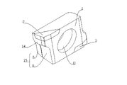
図1は、本発明の一実施形態に係るタンジェンシャル型フライスインサートの第1の斜視図である。図2は、本発明の一実施形態に係るタンジェンシャル型フライスインサートの第2の斜視図である。図3は、本発明の一実施形態に係るタンジェンシャル型フライスインサートの第3の斜視図である。図4は、本発明の一実施形態に係るタンジェンシャル型フライスインサートの正面図である。図1乃至図4に示すように、本実施形態おけるタンジェンシャル型フライスインサートは、インサートカーバイドベース1と、インサートベース1上に取りつけられたダブルカッターチップ構造と、を含み、ダブルカッターチップ構造は、第1カッターチップ2及び第2カッターチップ3を含んでいる。第1カッターチップ2及び第2カッターチップ3は、両方ともミリングのカッターチップであり、したがって、この実施形態におけるフライスインサートは、インデックス可能なフライスインサートであってもよい。インサートベース1の中央領域には、第1固定ネジ6を嵌め込み、タンジェンシャル型フライスインサートをフライスホイールに取り付けるように構成された取り付け穴11が存在する。
FIG. 1 is a first perspective view of a tangential milling insert according to an embodiment of the present invention. FIG. 2 is a second perspective view of a tangential milling insert according to an embodiment of the present invention. FIG. 3 is a third perspective view of a tangential milling insert according to an embodiment of the present invention. FIG. 4 is a front view of a tangential milling insert according to an embodiment of the present invention. As shown in FIGS. 1 to 4, the tangential type milling insert in the present embodiment includes an insert carbide base 1 and a double cutter tip structure mounted on the insert base 1. A
図4に示すように、インサートベース1の取り付け穴11の軸線に垂直な断面は、略四角形の断面であり、インサートベース1の断面の輪郭は四角形である。第1カッターチップ2及び第2カッターチップ3は、四角形のインサートベース1の対向する2つの頂点に取り付けられている。
As shown in FIG. 4, the cross section perpendicular to the axis of the mounting
第1カッターチップ2と第2カッターチップ3とを接続する機能に加えて、インサートベース1は、第1カッターチップ2を支持する機能をさらに備えていることがありうる。第2カッターチップ3は、第1カッターチップ2又は第2カッターチップ3に加えられる衝撃力を、材料表面をミリングする間にフライスホイールに伝達する。したがって、インサートベース1は、第1カッターチップ2及び第2カッターチップ3を支持するための支持部位を有する必要がある。第1カッターチップ2又は第2カッターチップ3がフライス加工中に振動しないことを保証するために、インサートベース1はさらに位置決め機能を有するべきである。
In addition to the function of connecting the
図1乃至図4に示すように、本実施形態に係るインサートベースは、第1側面12及び第2側面13を有しており、第1側面12及び第2側面13は、インサートベース1の2つの対向する側面であり、第1側面12は、第1カッターチップ2の後部カッター面に相当し、インサートベース1の第1側面12を形成する部分は、第1カッターチップ2に接続され、第1カッターチップ2を支持するように機能する。第2側面13は、第2カッターチップ3の後部カッター面に相当し、インサートベース1の第2側面13を形成する部分は、第2カッターチップ3と接続され、第2カッターチップ3を支持するように機能する。
As shown in FIGS. 1 to 4, the insert base according to the present embodiment has a
具体的に、第1側面12は、第1カッターチップ支持面14及び第1位置決め構造15を有しており、第1カッターチップ支持面14は、第1カッターチップ2の後部カッター面と直接接続されており、第1位置決め構造15は、第1カッターチップ支持面14に対してインサートベース1の内側に凹んでいる。同様に、第2側面13は、第2カッターチップ支持面16及び第2位置決め構造17を有しており、第2カッターチップ支持面16は、第2カッターチップ3の後部カッター面と直接接続されており、第2位置決め構造17は、第2カッターチップ支持面16に対してインサートベースの内側に凹んでいる。
Specifically, the
図4に示すように、第1位置決め構造15及び第2位置決め構造17は、四角形構造を有するインサートベース1の他の2つの頂点上に実質的に位置する。実際の加工において、第1位置決め構造15及び第2位置決め構造17は、インサートベース1の他の2つの頂点の材料を除去して形成された凹部領域の表面である。第1位置決め構造15が第1カッターチップ支持面14に対して凹んでいるので、フライス加工中に、第1位置決め構造15が第1カッターチップ2の後方カッター面領域として磨耗することはなく、位置決め精度は加工プロセスの影響を受ない。同様に、第2位置決め構造17は、第2カッターチップ支持面16を凹ませているので、フライス加工中に、第2位置決め構造17が第2カッターチップ3の後部カッター面領域として磨耗することはなく、加工プロセスの影響を受けない。第1カッターチップ2及び第2カッターチップ3を交換してフライスのカッターチップとして使用する場合には、第1位置決め構造15と第2位置決め構造17がそれぞれ取り付け穴11に一致して位置決めされ、フライスインサートの位置決め精度及び位置決め安定性を保証することができる。
As shown in FIG. 4, the
本実施形態におけるタンジェンシャル型フライスインサートは、回収可能なフライスインサートである。第1カッターチップ支持面14と、第1カッターチップ2の後側カッター面と、は同一平面上にあり、第2カッターチップ支持面16と第2カッターチップ3の後側カッター面と、は同一平面内にある。フライスインサートのカッターチップがある程度磨耗すると、鋭利化を必要とし、第1カッターチップ支持面14と第1カッターチップ2の後方カッター面とは同時に再研削されるが、第1位置決め構造15の面は再研削されない。同様に、第2カッターチップ支持面16と第2カッターチップ3の後側カッター面とは同時に再研削されるが、第2位置決め構造17の面は再研削されない。したがって、本実施形態におけるタンジェンシャル型フライスインサートの鋭利化コストは低い。
The tangential milling insert in this embodiment is a recoverable milling insert. The first cutter
本実施形態の第1位置決め構造15と第2位置決め構造17は、いずれも屈曲面構造を有しており、屈曲面構造の異なる面で異なる位置合わせを実現することができる。したがって、本実施形態の曲面構造の具体的な形状は、第1位置決め構造15を例にとるだけで紹介できる。図1乃至図3に示すように、本実施形態の第1位置決め構造15は、第1面Aと第2面Bとを含み、第1面Aと第2面Bは非平面である。ここで、第1面Aは、マルチ刃フライスの第1位置決め平面に適合するように構成され、第2面Bは、フライスインサートの位置を調整するために、第2面Bが第2固定ネジ7に適合すると、第1面Aはカッターホイール上の第1位置決め平面47から取り外される。
Both the
本実施形態における第2面Bは、第1面Aに対してインサートベース1の内側に傾斜した面である。図2及び図3に示すように、本実施形態における第1面Aは、第1平坦面A1と第1曲面A2とを有し、第1曲面A2は、第1平坦面A1と第1カッターチップ支持面14とを接続し、第2面Bは、第2平坦面B1と第1曲面B2とを有し、第2曲面B2は、第2平坦面B1と第1カッターチップ支持面14とを接続している。本実施形態では、第1曲面A2は、第1カッターチップ支持面14と第1平坦面A1との間の移行曲面として設定されているため、局所的な応力集中の問題を回避することができ、インサートベースは、損傷を防ぐことができる。また、本実施形態の第2曲面部B2は、取り付け穴の軸線と平行な軸線を有する円錐面であり、応力集中の問題を低減することに加えて、第2曲面B2は、後述する第2固定ネジ7との接触面積を増加させることもできる。
The second surface B in the present embodiment is a surface inclined inward of the insert base 1 with respect to the first surface A. As shown in FIGS. 2 and 3, the first side A in this embodiment, has a first Tan Taira surface A1 and the first curved surface A2, the first curved surface A2 has a first Tan Taira surface A1 first 1 connects the cutter
図5は、図4の方向Gにおける模式図である。図6は、図4の方向Iにおける模式図である。図7は、図4における方向Hの模式図である。図5から分かるように、本実施形態の第1曲面A2も、第1曲面A2の円錐度が第2曲面B2の円錐度より小さいことを除いて、取り付け穴の軸に平行な軸を有する円錐面である。図2、図3、及び図5に示すように、取り付け穴11の軸線に対する第1平坦面A1の角度は、第1曲面A2の円錐度であり、取り付け穴11の軸線に対する第2平坦面B1の角度は第2曲面B2の円錐度を示す。
FIG. 5 is a schematic diagram in the direction G of FIG. FIG. 6 is a schematic diagram in the direction I of FIG. FIG. 7 is a schematic diagram in the direction H in FIG. As can be seen from FIG. 5, the first curved surface A2 of the present embodiment is also a cone having an axis parallel to the axis of the mounting hole except that the conicity of the first curved surface A2 is smaller than the conical degree of the second curved surface B2. Surface. As shown in FIGS. 2, 3, and 5, the angle of the first Tan Taira surface A1 with respect to the axis of the mounting
図6及び図7に示すように、第1側面12の第1位置決め構造15と同様に、本実施形態の第2側面13の第2位置決め構造17は、第1平坦面A1と、第1曲面A2と、第2平坦面B1と、第2曲面B2と、を有する。さらに、図4乃至図7から分かるように、本実施形態のフライスインサートは、取り付け穴11の軸に対して中心対称である。
As shown in FIGS. 6 and 7, similarly to the
図8は、図4のN−Nに沿った断面図である。図9は、図4のK−Kに沿った断面図である。図10は、図10のJ−Jに沿った断面図である。図8乃至図10に示すように、本実施形態の取り付け穴部の領域はテーパ穴であり、フライスインサートの取り付け位置決めを実現する位置決めネジの位置決め平面との嵌合が容易である。 FIG. 8 is a cross-sectional view taken along line NN in FIG. FIG. 9 is a cross-sectional view taken along the line KK of FIG. 10 is a cross-sectional view taken along line JJ in FIG. As shown in FIGS. 8 to 10, the region of the mounting hole portion of the present embodiment is a tapered hole, and it is easy to fit with a positioning plane of a positioning screw that realizes mounting positioning of the milling insert.
図11は、図8の領域Fにおける模式図である。図11に示すように、インサートベースの厚さ方向の第1面Aの幅はDである。本実施形態では、第1面の幅Dは、インサートベースの厚さの1/3−1/2である。加えて、図11に示すように、第1面Aと第2面Bとのなす角度をαとする。1つの特定の用途では、αは10°〜30°、好ましくは12.5°であり得る。 FIG. 11 is a schematic diagram in the region F of FIG. As shown in FIG. 11, the width of the first surface A in the thickness direction of the insert base is D. In the present embodiment, the width D of the first surface is 1 / 3-1 / 2 of the thickness of the insert base. In addition, as shown in FIG. 11, the angle formed by the first surface A and the second surface B is α. In one particular application, α can be between 10 ° and 30 °, preferably 12.5 °.
1つの特定の用途では、本実施形態のインサートベース1は、好ましくは硬質合金鋼を使用することができ、第1カッターチップ2及び第2カッターチップ3は、好ましくは多結晶ダイヤモンド(PCD)または立方晶窒化ホウ素(PCBN)を使用することができる。
In one specific application, the insert base 1 of the present embodiment can preferably use hard alloy steel, and the
さらに、第1カッターチップ2及び第2カッターチップ3の前側カッター面は、切れ刃が破損するように切れ目を入れた設計にすることができる。
Furthermore, the front cutter surfaces of the
上記のタンジェンシャル型フライスインサートに加えて、本発明の一実施形態は、上記のタンジェンシャル型フライスインサートを使用するマルチ刃フライスをさらに提供する。 In addition to the above tangential milling insert, one embodiment of the present invention further provides a multi-blade milling using the above tangential milling insert.
図12は、本発明の一実施形態に係るマルチ刃フライスの概略図である。図13は、図12の領域Lにおける拡大図である。図12及び図13に示すように、本実施形態のマルチ刃フライスは、カッターホイールベース4、タンジェンシャル型フライスインサート5、第1固定ネジ6、第2固定ネジ7、及びダイナミックバランス調整ネジ8を含む。
FIG. 12 is a schematic view of a multi-blade milling cutter according to an embodiment of the present invention. FIG. 13 is an enlarged view of region L in FIG. As shown in FIGS. 12 and 13, the multi-blade mill of this embodiment includes a
図14は、本発明の一実施形態に係るカッターホイールベースの概略図である。図15は、本発明の一実施形態に係るカッターホイールベースの第1カッターベース及び第2カッターベースの分解図である。図16は、図14の領域Mにおける拡大図である。図14乃至図16に示すように、カッターホイールベース4は、第1カッターベース41と第2カッターベース42とを有し、第1カッターベース41と第2カッターベース42とは固定的に接続されており、第1カッターベース41は、カッターシャンクを介して機械の駆動シャフトに接続され、第2カッターベース42は、タンジェンシャル型フライスインサート5を取り付けるように構成される。
FIG. 14 is a schematic view of a cutter wheel base according to an embodiment of the present invention. FIG. 15 is an exploded view of the first cutter base and the second cutter base of the cutter wheel base according to an embodiment of the present invention. FIG. 16 is an enlarged view of region M in FIG. As shown in FIGS. 14 to 16, the
マルチ刃フライスが材料の表面をミリングするとき、タンジェンシャル型フライスインサート5によって第2カッターベース42に加えられる応力は非常に大きい。第2カッターベース42の変形を防止するために、本実施形態における第2カッターベース42の材質は、スチール等の硬質材であることが好ましく、第1カッターベース41の材料は、軽合金、例えば、アルミニウム合金またはチタン合金であることが好ましい。したがって、本実施形態の第1カッターベース41の硬度は、第2カッターベース42の硬度よりも小さい。
When the multi-blade milling mills the surface of the material, the stress applied to the
図15に示すように、本実施形態の第2カッターベース42は、円形リング状であり、図2に示すように、図15に示すように、本実施形態の第2カッターベース42は、円形リング状であり、第1カッターベース41の底面はシャフト−ショルダー構造を有し、第2カッターベース42は、第1カッターベース41のシャフト−ショルダー構造に固定して取り付けられている。しかし、他の実施形態では、第2カッターベース42を第1カッターベース41の端面に嵌合接続し、第1カッターベース41の端面を第2カッターベース42の位置決め平面としてもよい。
As shown in FIG. 15, the
図14及び図16に示すように、第2カッターベース42は、タンジェンシャル型フライスインサート5を取り付け、位置決めするための構造を有する。具体的には、第2カッターベース42の表面には、タンジェンシャル型フライスインサート5が挿入されるインサート取り付け溝43が設けられている。インサート取り付け溝43の底面には、第1固定ネジ6を嵌合するための第1ネジ穴44が設けられている。インサート取り付け溝43の側面には、第1位置決め平面47がさらに設定されている。第2カッターベース42の第1位置決め平面47に隣接する領域には、第2固定ネジ7に嵌合する第2ネジ穴45が設けられ、第2ネジ穴45の軸線は第1ネジ穴44の軸線と平行であり、さらに、インサート取り付け溝と連通する退避溝46がさらに存在する。
As shown in FIGS. 14 and 16, the
ダブルカッターチップ構造を有するタンジェンシャル型フライスインサート5がインサート取り付け溝43に装着されると、第1カッターチップ2及び第2カッターチップ3の一方が第2カッターベース42から突出し、他方が退避溝46の側面に接触することなく退避溝46内に配置される。第1固定ネジ6は、取り付け穴11を貫通し、タンジェンシャル型フライスインサート5を取り付け溝に固定する。同時に、第1位置決め平面47または第2固定ネジ7が、タンジェンシャル型フライスインサート5の対応する位置決め構造に適合し、それによって位置決めが実現される。
When the tangential
図17は、図12の第2位置決めネジが取り付けられていないO−Oに沿った断面における模式図である。図17に示すように、マルチ刃フライスの加工精度がそれほど高くない場合には、タンジェンシャル型フライスインサート5の第1面Aは、第1カッターベース41の第1位置決め平面47に直接適用されてもよく、第1位置決め平面47と第1固定ネジ6との嵌合を介してタンジェンシャル型フライスインサート5を固定することができる。この時点で、第2固定ネジ7は、第2ネジ穴45に取り付けられていなくてもよいし、第2ネジ穴45に取り付けられてカウンタウェイトとしてのみ機能してもよい。
FIG. 17 is a schematic diagram in a cross section taken along OO in which the second set screw of FIG. 12 is not attached. As shown in FIG. 17, when the processing accuracy of the multi-blade milling is not so high, the first surface A of the
マルチ刃フライスの加工精度に対する要求が非常に高い場合、種々の誤差のために、第2カッターベース42から突き出ているタンジェンシャル型フライスインサート5のカッターチップは、同じ面内にない。この時点で、第2カッターベース42から突出しているタンジェンシャル型フライスインサート5のサイズは、第2位置決めネジ7と第2面Bをタンジェンシャル型フライスインサート5に嵌め込むことによって調整することができ、カッターチップを平らにすることができる。図18は、第2位置決めネジが第2面と嵌合するときの断面図である。図18に示すように、第2固定ネジ7は、円錐面を介して第2面Bに嵌合する。調整が必要な場合には、第2固定ネジ7が第2ネジ穴45にネジ込まれると、第2固定ネジ7の円錐面が第2面Bを外側に押して、タンジェンシャル型フライスインサート5を全体として外側に移動させる。調整の間に、最初に固定されたフライスインサートが外向きに移動できるように、最初に第1固定ネジ6を緩めなければならない。
When the demand for processing accuracy of the multi-blade milling is very high, the cutter tip of the
図19は、本発明の一実施形態に係るマルチ刃フライスインサートの部分切欠き図である。また、図19は、タンジェンシャル型フライスインサート5における第2固定ネジ7と第2面Bとの嵌合を示している。加えて、図19に示すように、本実施形態に係るマルチ刃フライスは、第1カッターベース41に固定的に接続され、第2カッターベース42と一定の間隙を有する冷却液スプレープレート48によってセットされる。冷却液スプレープレート48には案内溝が設けられている。冷却液が第1カッターベース41の軸心を介して冷却液スプレープレート48に供給された後、案内溝によって加速されて遠心分離された後に間隙からはじき飛ばされる。
FIG. 19 is a partial cutaway view of a multi-blade milling insert according to one embodiment of the present invention. FIG. 19 shows the fitting between the
また、本実施形態のダイナミックバランス調整ネジ8は、第1カッターベース41の外周面に取り付けられている。各タンジェンシャル型フライスインサート5の後に、第1固定ネジ6及び第2固定ネジ7が取り付けられ、マルチ刃フライスの重心が車軸中心にない場合は、各ダイナミックバランス調整ネジ8の位置を変更することによって車軸中心に合わせることができる。
The dynamic
本発明の実施形態に係るタンジェンシャル型フライスインサート及びマルチ刃フライスは、上記で詳細に紹介した。本発明の原理および実施形態は、この部分の特定の実施形態によって例示されており、上記の実施形態の図示は、本発明のコア概念のより良い理解のためにのみ使用される。本発明の原理から逸脱することなく、当業者が創造的な仕事をしなくても得られる他の実施形態はすべて、本発明の保護範囲に関する。 The tangential milling insert and multi-blade milling according to embodiments of the present invention were introduced in detail above. The principles and embodiments of the present invention are illustrated by specific embodiments of this part, and the illustration of the above embodiments is used only for a better understanding of the core concept of the present invention. All other embodiments obtained by persons of ordinary skill in the art without creative work without departing from the principles of the invention relate to the protection scope of the invention.
1:インサートベース
11:取り付け穴
12:第1側面
13:第2側面
14:第1カッターチップ支持面
15:第1位置決め構造
16:第2カッターチップ支持面
17:第2位置決め構造
A:第1面
A1:第1平坦面
A2:第1曲面
B:第2面
B1:第2平坦面
B2:第2曲面
2:第1カッターチップ
3:第2カッターチップ
4:カッターホイールベース
41:第1カッターベース
42:第2カッターベース
43:インサート取り付け溝
44:第1ネジ穴
45:第2ネジ穴
46:退避溝
47:第1位置決め平面
48:冷却液スプレープレート
5:タンジェンシャル型フライスインサート
6:第1固定ネジ
7:第2固定ネジ
8:ダイナミックバランス調整ネジ
1: Insert base 11: Mounting hole 12: First side surface 13: Second side surface 14: First cutter tip support surface 15: First positioning structure 16: Second cutter tip support surface 17: Second positioning structure A: First Surface A1: First flat surface A2: First curved surface B: Second surface B1: Second flat surface B2: Second curved surface 2: First cutter tip 3: Second cutter tip 4: Cutter wheel base 41: First cutter Base 42: Second cutter base 43: Insert mounting groove 44: First screw hole 45: Second screw hole 46: Retraction groove 47: First positioning plane 48: Coolant spray plate 5: Tangential milling insert 6: First 1 fixing screw 7: second fixing screw 8: dynamic balance adjusting screw
Claims (7)
インサートベース(1)とカッターチップユニットとを備え、
前記インサートベースには、前記タンジェンシャル型フライスインサートをフライスホイールに取り付けるための取り付け穴(11)が設けられ、
前記カッターチップユニットは、インサートベース(1)に取り付けられ、
前記カッターチップユニットは、ダブルカッターチップ構造を有し、
前記ダブルカッターチップ構造は、第1カッターチップ(2)及び第2カッターチップ(3)を含み、
取り付け穴の軸線に垂直な前記インサートベース(1)の断面は、4つの頂点を有し、
前記第1カッターチップ(2)及び第2カッターチップ(3)は、互いに対応する位置でインサートベース(1)上の2つの頂点上に配置され、
前記インサートベース(1)は、第1側面(12)と、前記第1側面(12)に対向する第2側面(13)と、を有し、
第1側面(12)には、第1カッターチップ支持面(14)と第1位置決め構造(15)が設けられ、
第1位置決め構造(15)は、第1カッターチップ支持面(14)に対して前記インサートベース(1)の内側に凹んでおり、
第2側面(13)には、第2カッターチップ支持面(16)と第2位置決め構造(17)が設けられ、
第2位置決め構造(17)は、第2カッターチップ支持面(16)に対してインサートベース(1)の内側に凹んでおり、
前記第1位置決め構造(15)及び前記第2位置決め構造(17)は、両方とも曲げられた平面構造を有し、
前記曲げられた平面構造は、第1面(A)及び第2面(B)を含み、前記第2面(B)は、前記第1面(A)に対して前記インサートベース(1)の内側に傾斜している、タンジェンシャル型フライスインサート。 A tangential milling insert,
An insert base (1) and a cutter tip unit;
The insert base is provided with an attachment hole (11) for attaching the tangential milling insert to a milling wheel,
The cutter tip unit is attached to the insert base (1),
The cutter tip unit has a double cutter tip structure,
The double cutter tip structure includes a first cutter tip (2) and a second cutter tip (3),
The section of the insert base (1) perpendicular to the axis of the mounting hole has four vertices,
The first cutter tip (2) and the second cutter tip (3) are arranged on two vertices on the insert base (1) at positions corresponding to each other,
The insert base (1) has a first side surface (12) and a second side surface (13) facing the first side surface (12),
The first side surface (12) is provided with a first cutter tip support surface (14) and a first positioning structure (15),
The first positioning structure (15) is recessed inside the insert base (1) with respect to the first cutter tip support surface (14),
The second side surface (13) is provided with a second cutter tip support surface (16) and a second positioning structure (17),
The second positioning structure (17) is recessed inside the insert base (1) with respect to the second cutter tip support surface (16) ,
The first positioning structure (15) and the second positioning structure (17) both have a bent planar structure,
The bent planar structure includes a first surface (A) and a second surface (B), and the second surface (B) is formed on the insert base (1) with respect to the first surface (A). Tangential milling insert, slanted inward .
前記第1位置決め構造(15)における前記第1曲面(A2)は、前記第1カッターチップ支持面(14)と、前記第1位置決め構造(15)における第1平坦面(A1)と、の間に位置し、
前記第2位置決め構造(17)における前記第1曲面(A2)は、第2カッターチップ支持面(16)と、前記第2位置決め構造(17)における第1平坦面(A1)との間に位置し、
前記第2面(B)は、第2平坦面(B1)及び第2曲面(B2)を有し、
前記第1位置決め構造(15)における前記第2曲面(B2)は、前記第1カッターチップ支持面(14)と、前記第1位置決め構造(15)における第2平坦面(B1)と、の間に位置し、
前記第2位置決め構造(17)における前記第2曲面(B2)は、第2カッターチップ支持面(16)と、前記第2位置決め構造(17)における第2平坦面(B1)とで接続される、請求項1に記載のタンジェンシャル型フライスインサート。 The first surface (A) has a first flat surface (A1) and a first curved surface (A2),
The first curved surface (A2) in the first positioning structure (15) is between the first cutter tip support surface (14) and the first flat surface (A1) in the first positioning structure (15). Located in
The first curved surface (A2) in the second positioning structure (17) is located between the second cutter tip support surface (16) and the first flat surface (A1) in the second positioning structure (17). And
The second surface (B) has a second flat surface (B1) and a second curved surface (B2),
The second curved surface (B2) in the first positioning structure (15) is between the first cutter tip support surface (14) and the second flat surface (B1) in the first positioning structure (15). Located in
The second curved surface (B2) in the second positioning structure (17) is connected by the second cutter tip support surface (16) and the second flat surface (B1) in the second positioning structure (17). The tangential type milling insert according to claim 1 .
前記カッターホイールベース(4)は、第1カッターベース(41)及び第2カッターベース(42)を含み、
前記第1カッターベース(41)は、第2カッターベース(42)と、前記第2カッターベース(42)に設けられた前記タンジェンシャル型フライスインサート(5)と、に接続され、
前記ネジアセンブリは、ダイナミックバランス調整ネジ(8)と、取り付け及び位置決めネジセットと、を含み、
前記ダイナミックバランス調整ネジ(8)は、前記第1カッターベース(41)に設けられ、
前記タンジェンシャル型フライスインサート(5)は、取り付け及び位置決めネジセットを介して、前記第2カッターベース(42)に接続され、
前記第2カッターベース(42)は、前記タンジェンシャル型フライスインサート(5)を取り付けるためのインサート取り付け溝(43)と、インサート取り付け溝(43)の底面に設けられた第1ネジ穴(44)と、前記インサート取り付け溝(43)に連通する退避溝(46)と、を含み、
前記タンジェンシャル型フライスインサート(5)は、前記インサート取り付け溝(43)に装着されると、未使用のカッターチップ構造が退避溝(46)内に配置され、
前記位置決め構造は、インサート取り付け溝(43)の側方に位置する第1位置決め平面(47)と、インサート取り付け溝(43)の側面に取り付けられた第2固定ネジ(7)とを含み、
前記カッターホイールベース(4)は、第2固定ネジ(7)に適合する第2ネジ穴(45)を含み、
前記第2ネジ穴(45)の軸線は第1ネジ穴(44)の軸線と平行である、マルチ刃フライス。 A cutter wheel base (4), a screw assembly, and a tangential milling insert (5) according to any one of claims 1 to 4 ,
The cutter wheel base (4) includes a first cutter base (41) and a second cutter base (42),
The first cutter base (41) is connected to a second cutter base (42) and the tangential type milling insert (5) provided on the second cutter base (42),
The screw assembly includes a dynamic balance adjustment screw (8) and a mounting and positioning screw set,
The dynamic balance adjustment screw (8) is provided on the first cutter base (41),
The tangential milling insert (5) is connected to the second cutter base (42) via a mounting and set screw set,
The second cutter base (42) includes an insert mounting groove (43) for mounting the tangential milling insert (5), and a first screw hole (44) provided on the bottom surface of the insert mounting groove (43). And a retracting groove (46) communicating with the insert mounting groove (43),
When the tangential type milling insert (5) is mounted in the insert mounting groove (43), an unused cutter tip structure is disposed in the retracting groove (46),
The positioning structure includes a first positioning plane (47) positioned on the side of the insert mounting groove (43), and a second fixing screw (7) mounted on a side surface of the insert mounting groove (43),
The cutter wheel base (4) includes a second screw hole (45) that fits a second fixing screw (7),
The multi-blade milling machine, wherein the axis of the second screw hole (45) is parallel to the axis of the first screw hole (44).
前記第1固定ネジ(6)は、前記タンジェンシャル型フライスインサート(5)の取り付け穴(11)と一致し、前記タンジェンシャル型フライスインサート(5)を前記第2カッターベース(42)に取り付け、
前記第2固定ネジ(7)は、前記タンジェンシャル型フライスインサート(5)の前記第1位置決め構造(15)又は前記第2位置決め構造(17)と一致し、前記タンジェンシャル型フライスインサート(5)と前記第2カッターベース(42)との相対位置を位置決めする、請求項5に記載のマルチ刃フライス。 The mounting and positioning screw set includes a first fixing screw (6) and a second fixing screw (7),
The first fixing screw (6) coincides with the mounting hole (11) of the tangential milling insert (5), and the tangential milling insert (5) is attached to the second cutter base (42).
The second fixing screw (7) coincides with the first positioning structure (15) or the second positioning structure (17) of the tangential milling insert (5), and the tangential milling insert (5). The multi-blade milling machine according to claim 5 , wherein a relative position between the first cutter base and the second cutter base is positioned.
The multi-blade milling machine according to claim 6 , wherein the hardness of the first cutter base (41) is lower than the hardness of the second cutter base (42).
Applications Claiming Priority (5)
| Application Number | Priority Date | Filing Date | Title |
|---|---|---|---|
| CN201520599136.9 | 2015-08-10 | ||
| CN201520599364.6 | 2015-08-10 | ||
| CN201520599364.6U CN204843084U (en) | 2015-08-10 | 2015-08-10 | Close tooth -like milling cutter dish |
| CN201520599136.9U CN205085448U (en) | 2015-08-10 | 2015-08-10 | Immediately, adorn formula milling cutter piece |
| PCT/CN2016/093628 WO2017024997A1 (en) | 2015-08-10 | 2016-08-05 | Vertical milling insert and dense gear milling cutter |
Publications (2)
| Publication Number | Publication Date |
|---|---|
| JP2017528328A JP2017528328A (en) | 2017-09-28 |
| JP6423080B2 true JP6423080B2 (en) | 2018-11-14 |
Family
ID=57984051
Family Applications (1)
| Application Number | Title | Priority Date | Filing Date |
|---|---|---|---|
| JP2017507873A Active JP6423080B2 (en) | 2015-08-10 | 2016-08-05 | Tangential milling insert and multi-blade milling |
Country Status (4)
| Country | Link |
|---|---|
| US (1) | US10220450B2 (en) |
| JP (1) | JP6423080B2 (en) |
| DE (1) | DE112016000109B4 (en) |
| WO (1) | WO2017024997A1 (en) |
Families Citing this family (8)
| Publication number | Priority date | Publication date | Assignee | Title |
|---|---|---|---|---|
| KR101469135B1 (en) * | 2014-07-08 | 2014-12-04 | 한국야금 주식회사 | Cutting insert and cutting tool for mounting the same |
| EP3072616B1 (en) * | 2015-03-25 | 2018-10-10 | Sandvik Intellectual Property AB | Cutting insert and milling tool |
| EP3305449B1 (en) * | 2016-10-05 | 2019-07-03 | Sandvik Intellectual Property AB | A face milling tool and a tangential cutting insert therefor |
| DE102017112374A1 (en) * | 2017-06-06 | 2018-12-06 | Komet Group Gmbh | Milling tool with changeable cutting ring |
| CN109226850A (en) * | 2018-11-02 | 2019-01-18 | 常州市海力工具有限公司 | A kind of micro-nano composite coating precision milling cutter based on diamond |
| CN111604529A (en) * | 2020-06-30 | 2020-09-01 | 北京沃尔德金刚石工具股份有限公司 | Milling cutter |
| CN112916931A (en) * | 2021-01-22 | 2021-06-08 | 大连理工大学 | High-precision large-diameter insert type disc milling cutter with finely adjustable blade |
| CN115026341A (en) * | 2022-06-21 | 2022-09-09 | 安庆中船动力配套有限公司 | Cutter for processing asymmetric R-angle ring groove of connecting rod |
Family Cites Families (25)
| Publication number | Priority date | Publication date | Assignee | Title |
|---|---|---|---|---|
| DE4437426A1 (en) * | 1994-10-20 | 1996-04-25 | Widia Heinlein Gmbh | Cutter |
| JPH10508259A (en) * | 1995-06-06 | 1998-08-18 | ケンナメタル インコーポレイテッド | High-speed milling of cartridge type |
| IL117552A (en) * | 1995-09-18 | 2000-02-17 | Iscar Ltd | Cutting insert |
| IL115338A (en) | 1995-09-18 | 1999-07-14 | Iscar Ltd | Exchangeable cutting insert and a tool assembly for use therewith |
| US6450738B1 (en) * | 2001-02-08 | 2002-09-17 | Ingersoll Cutting Tool Company | Cutting fluid distributor for milling cutters |
| US7168512B2 (en) * | 2001-09-06 | 2007-01-30 | Kennametal Inc. | Cutting insert and milling cutter with such a cutting insert |
| DE10143843A1 (en) | 2001-09-06 | 2003-03-27 | Kennametal Inc | Cutting plate and milling tool has base surface of plate facing conical sleeve shaped surface section and forming cutting edge at acute angle whilst planar surface section forms obtuse angle with opposite base face |
| CA2729497A1 (en) | 2002-02-21 | 2003-08-28 | Element Six (Pty) Ltd | Tool insert |
| DE202004008642U1 (en) | 2004-05-27 | 2005-09-29 | Kennametal Inc. | milling tool |
| US7878738B2 (en) * | 2005-05-21 | 2011-02-01 | Keenametal Inc. | Milling cutter and a cutting insert for a milling cutter |
| DE102005045751A1 (en) | 2005-09-23 | 2007-03-29 | Sandvik Intellectual Property Ab | Tool e.g. milling tool, for e.g. milling workpiece, has carrier body, and seat for receiving cutting plate, where seat is formed in adjusting unit that is rotatable around rotary axis relative to carrier body |
| US7390150B2 (en) * | 2006-05-03 | 2008-06-24 | Valenite Llc | Cutting tool with adjustable indexable cutting insert |
| KR101526610B1 (en) | 2006-11-13 | 2015-06-05 | 귀링 카게 | Metal-cutting tool |
| DE202006017881U1 (en) | 2006-11-13 | 2008-03-27 | Gühring Ohg | Machining tool |
| IL182078A (en) * | 2007-03-20 | 2011-09-27 | Iscar Ltd | System for attaching a cutting member to a cutter |
| SE531363C2 (en) * | 2007-03-30 | 2009-03-10 | Seco Tools Ab | Cutting tool with interchangeable cutting support cassette |
| US8454277B2 (en) * | 2008-12-18 | 2013-06-04 | Kennametal Inc. | Toolholder and toolholder assembly with elongated seating pads |
| IL196440A (en) * | 2009-01-11 | 2012-03-29 | Iscar Ltd | Adjustment mechanism |
| KR101067161B1 (en) * | 2010-01-06 | 2011-09-22 | 대구텍 유한회사 | Cutting inserts for internal grooving and toolholders for them |
| DE102011112952B3 (en) * | 2011-09-13 | 2013-03-07 | Kennametal Inc. | Reaming tool and adjusting screw for a fine adjustment mechanism, especially in a reaming tool |
| CN202428018U (en) | 2011-11-30 | 2012-09-12 | 郑州市钻石精密制造有限公司 | Rhombic indexable polycrystalline cubic boron nitride milling cutter blade |
| JP2014117775A (en) | 2012-12-17 | 2014-06-30 | Mitsubishi Materials Corp | Cutting insert |
| US9527142B2 (en) | 2013-02-19 | 2016-12-27 | Iscar, Ltd. | High speed milling tool and tangential ramping milling insert therefor |
| CN205085448U (en) | 2015-08-10 | 2016-03-16 | 北京沃尔德金刚石工具股份有限公司 | Immediately, adorn formula milling cutter piece |
| CN204843084U (en) | 2015-08-10 | 2015-12-09 | 北京沃尔德金刚石工具股份有限公司 | Close tooth -like milling cutter dish |
-
2016
- 2016-08-05 JP JP2017507873A patent/JP6423080B2/en active Active
- 2016-08-05 WO PCT/CN2016/093628 patent/WO2017024997A1/en active Application Filing
- 2016-08-05 US US15/319,113 patent/US10220450B2/en active Active
- 2016-08-05 DE DE112016000109.6T patent/DE112016000109B4/en active Active
Also Published As
| Publication number | Publication date |
|---|---|
| US20170197256A1 (en) | 2017-07-13 |
| DE112016000109T5 (en) | 2017-05-24 |
| US10220450B2 (en) | 2019-03-05 |
| DE112016000109B4 (en) | 2022-07-28 |
| WO2017024997A1 (en) | 2017-02-16 |
| JP2017528328A (en) | 2017-09-28 |
Similar Documents
| Publication | Publication Date | Title |
|---|---|---|
| JP6423080B2 (en) | Tangential milling insert and multi-blade milling | |
| JP5089616B2 (en) | Cutting inserts and milling tools | |
| JP4842015B2 (en) | Cutter wheel tip holder for brittle materials | |
| JP5491505B2 (en) | Milling and cutting tips therefor | |
| US10173275B2 (en) | Cutting tool with replaceable abutment members and toolholder and cutting insert therefor | |
| US10201855B2 (en) | Cutting insert, tool body and cutting tool | |
| WO2007142224A1 (en) | Cutting tool and cutting insert | |
| CN107199363B (en) | Face milling cutter head and face milling cutter using same | |
| JP2008229744A (en) | Cutting insert and insert removable rotary cutting tool | |
| US10850331B2 (en) | Cutting tool and method for machining annular groove | |
| JP5853830B2 (en) | Cutting edge replaceable cutting tool and its cutting edge position adjusting method | |
| WO2019010915A1 (en) | Indexable face milling cutting insert and face milling cutting head using the cutting insert | |
| KR102390169B1 (en) | Milling cutter attached wedge type blade having sequential cutting tip | |
| KR102325709B1 (en) | Face milling tools and thus tangential cutting inserts | |
| JP2006150535A (en) | Cutting tool | |
| JP2023102449A (en) | Tool head of head replacement type cutting tool | |
| JP3997518B2 (en) | Throwaway milling | |
| JP4134478B2 (en) | Throwaway tip | |
| JP2007038330A (en) | Cutting cartridge and cutting tool | |
| CN110640168A (en) | Combined turning tool with adjustable center | |
| JP2005342850A (en) | Throwaway type face milling cutter and mounting member of supporter for use in face milling cutter | |
| JP2001079709A (en) | End mill | |
| JP5315749B2 (en) | Insert detachable cutter | |
| JP2008080469A (en) | Throw-away type rotating tool and tip mounted to it | |
| JP2017221982A (en) | Tip exchange type cutting tool holder and tip exchange type cutting tool |
Legal Events
| Date | Code | Title | Description |
|---|---|---|---|
| A621 | Written request for application examination |
Free format text: JAPANESE INTERMEDIATE CODE: A621 Effective date: 20170207 |
|
| A977 | Report on retrieval |
Free format text: JAPANESE INTERMEDIATE CODE: A971007 Effective date: 20180129 |
|
| A131 | Notification of reasons for refusal |
Free format text: JAPANESE INTERMEDIATE CODE: A131 Effective date: 20180206 |
|
| A521 | Request for written amendment filed |
Free format text: JAPANESE INTERMEDIATE CODE: A523 Effective date: 20180502 |
|
| A131 | Notification of reasons for refusal |
Free format text: JAPANESE INTERMEDIATE CODE: A131 Effective date: 20180529 |
|
| A521 | Request for written amendment filed |
Free format text: JAPANESE INTERMEDIATE CODE: A523 Effective date: 20180829 |
|
| TRDD | Decision of grant or rejection written | ||
| A01 | Written decision to grant a patent or to grant a registration (utility model) |
Free format text: JAPANESE INTERMEDIATE CODE: A01 Effective date: 20180925 |
|
| A61 | First payment of annual fees (during grant procedure) |
Free format text: JAPANESE INTERMEDIATE CODE: A61 Effective date: 20181017 |
|
| R150 | Certificate of patent or registration of utility model |
Ref document number: 6423080 Country of ref document: JP Free format text: JAPANESE INTERMEDIATE CODE: R150 |
|
| R250 | Receipt of annual fees |
Free format text: JAPANESE INTERMEDIATE CODE: R250 |
|
| R250 | Receipt of annual fees |
Free format text: JAPANESE INTERMEDIATE CODE: R250 |
|
| R250 | Receipt of annual fees |
Free format text: JAPANESE INTERMEDIATE CODE: R250 |
|
| R250 | Receipt of annual fees |
Free format text: JAPANESE INTERMEDIATE CODE: R250 |