JP6406916B2 - Cartridge and cartridge manufacturing method - Google Patents
Cartridge and cartridge manufacturing method Download PDFInfo
- Publication number
- JP6406916B2 JP6406916B2 JP2014157756A JP2014157756A JP6406916B2 JP 6406916 B2 JP6406916 B2 JP 6406916B2 JP 2014157756 A JP2014157756 A JP 2014157756A JP 2014157756 A JP2014157756 A JP 2014157756A JP 6406916 B2 JP6406916 B2 JP 6406916B2
- Authority
- JP
- Japan
- Prior art keywords
- thin plate
- plate member
- cartridge
- developer
- sheet
- Prior art date
- Legal status (The legal status is an assumption and is not a legal conclusion. Google has not performed a legal analysis and makes no representation as to the accuracy of the status listed.)
- Active
Links
- 238000004519 manufacturing process Methods 0.000 title claims description 25
- 238000004140 cleaning Methods 0.000 claims description 85
- 238000005304 joining Methods 0.000 claims description 41
- 238000000034 method Methods 0.000 claims description 29
- 239000000463 material Substances 0.000 claims description 25
- 229920005989 resin Polymers 0.000 claims description 23
- 239000011347 resin Substances 0.000 claims description 23
- 229920005992 thermoplastic resin Polymers 0.000 claims description 6
- 238000011144 upstream manufacturing Methods 0.000 claims description 5
- 239000002184 metal Substances 0.000 claims 5
- 230000001678 irradiating effect Effects 0.000 claims 1
- 230000002265 prevention Effects 0.000 description 31
- 230000000694 effects Effects 0.000 description 10
- 238000012986 modification Methods 0.000 description 10
- 230000004048 modification Effects 0.000 description 10
- 239000006096 absorbing agent Substances 0.000 description 9
- 239000002699 waste material Substances 0.000 description 9
- 238000007664 blowing Methods 0.000 description 5
- 239000012943 hotmelt Substances 0.000 description 5
- 230000002093 peripheral effect Effects 0.000 description 5
- 238000003825 pressing Methods 0.000 description 5
- 239000000853 adhesive Substances 0.000 description 4
- 230000001070 adhesive effect Effects 0.000 description 4
- 238000010586 diagram Methods 0.000 description 4
- 230000001105 regulatory effect Effects 0.000 description 4
- 238000003756 stirring Methods 0.000 description 3
- 229910052799 carbon Inorganic materials 0.000 description 2
- 239000006229 carbon black Substances 0.000 description 2
- 229920001971 elastomer Polymers 0.000 description 2
- 239000000806 elastomer Substances 0.000 description 2
- 239000000155 melt Substances 0.000 description 2
- 238000000465 moulding Methods 0.000 description 2
- 238000007789 sealing Methods 0.000 description 2
- 238000003466 welding Methods 0.000 description 2
- NIXOWILDQLNWCW-UHFFFAOYSA-N acrylic acid group Chemical group C(C=C)(=O)O NIXOWILDQLNWCW-UHFFFAOYSA-N 0.000 description 1
- 238000007599 discharging Methods 0.000 description 1
- 238000006073 displacement reaction Methods 0.000 description 1
- 239000007788 liquid Substances 0.000 description 1
- 229920000728 polyester Polymers 0.000 description 1
- 229920002379 silicone rubber Polymers 0.000 description 1
- 239000004945 silicone rubber Substances 0.000 description 1
- 238000003860 storage Methods 0.000 description 1
Images


Classifications
-
- G—PHYSICS
- G03—PHOTOGRAPHY; CINEMATOGRAPHY; ANALOGOUS TECHNIQUES USING WAVES OTHER THAN OPTICAL WAVES; ELECTROGRAPHY; HOLOGRAPHY
- G03G—ELECTROGRAPHY; ELECTROPHOTOGRAPHY; MAGNETOGRAPHY
- G03G15/00—Apparatus for electrographic processes using a charge pattern
- G03G15/06—Apparatus for electrographic processes using a charge pattern for developing
- G03G15/08—Apparatus for electrographic processes using a charge pattern for developing using a solid developer, e.g. powder developer
- G03G15/0894—Reconditioning of the developer unit, i.e. reusing or recycling parts of the unit, e.g. resealing of the unit before refilling with toner
-
- B—PERFORMING OPERATIONS; TRANSPORTING
- B29—WORKING OF PLASTICS; WORKING OF SUBSTANCES IN A PLASTIC STATE IN GENERAL
- B29C—SHAPING OR JOINING OF PLASTICS; SHAPING OF MATERIAL IN A PLASTIC STATE, NOT OTHERWISE PROVIDED FOR; AFTER-TREATMENT OF THE SHAPED PRODUCTS, e.g. REPAIRING
- B29C65/00—Joining or sealing of preformed parts, e.g. welding of plastics materials; Apparatus therefor
- B29C65/02—Joining or sealing of preformed parts, e.g. welding of plastics materials; Apparatus therefor by heating, with or without pressure
- B29C65/14—Joining or sealing of preformed parts, e.g. welding of plastics materials; Apparatus therefor by heating, with or without pressure using wave energy, i.e. electromagnetic radiation, or particle radiation
- B29C65/16—Laser beams
- B29C65/1629—Laser beams characterised by the way of heating the interface
- B29C65/1635—Laser beams characterised by the way of heating the interface at least passing through one of the parts to be joined, i.e. laser transmission welding
-
- B—PERFORMING OPERATIONS; TRANSPORTING
- B29—WORKING OF PLASTICS; WORKING OF SUBSTANCES IN A PLASTIC STATE IN GENERAL
- B29C—SHAPING OR JOINING OF PLASTICS; SHAPING OF MATERIAL IN A PLASTIC STATE, NOT OTHERWISE PROVIDED FOR; AFTER-TREATMENT OF THE SHAPED PRODUCTS, e.g. REPAIRING
- B29C65/00—Joining or sealing of preformed parts, e.g. welding of plastics materials; Apparatus therefor
- B29C65/02—Joining or sealing of preformed parts, e.g. welding of plastics materials; Apparatus therefor by heating, with or without pressure
- B29C65/14—Joining or sealing of preformed parts, e.g. welding of plastics materials; Apparatus therefor by heating, with or without pressure using wave energy, i.e. electromagnetic radiation, or particle radiation
- B29C65/16—Laser beams
- B29C65/1603—Laser beams characterised by the type of electromagnetic radiation
- B29C65/1612—Infrared [IR] radiation, e.g. by infrared lasers
- B29C65/1616—Near infrared radiation [NIR], e.g. by YAG lasers
-
- B—PERFORMING OPERATIONS; TRANSPORTING
- B29—WORKING OF PLASTICS; WORKING OF SUBSTANCES IN A PLASTIC STATE IN GENERAL
- B29C—SHAPING OR JOINING OF PLASTICS; SHAPING OF MATERIAL IN A PLASTIC STATE, NOT OTHERWISE PROVIDED FOR; AFTER-TREATMENT OF THE SHAPED PRODUCTS, e.g. REPAIRING
- B29C65/00—Joining or sealing of preformed parts, e.g. welding of plastics materials; Apparatus therefor
- B29C65/02—Joining or sealing of preformed parts, e.g. welding of plastics materials; Apparatus therefor by heating, with or without pressure
- B29C65/14—Joining or sealing of preformed parts, e.g. welding of plastics materials; Apparatus therefor by heating, with or without pressure using wave energy, i.e. electromagnetic radiation, or particle radiation
- B29C65/16—Laser beams
- B29C65/1629—Laser beams characterised by the way of heating the interface
- B29C65/1654—Laser beams characterised by the way of heating the interface scanning at least one of the parts to be joined
- B29C65/1658—Laser beams characterised by the way of heating the interface scanning at least one of the parts to be joined scanning once, e.g. contour laser welding
-
- B—PERFORMING OPERATIONS; TRANSPORTING
- B29—WORKING OF PLASTICS; WORKING OF SUBSTANCES IN A PLASTIC STATE IN GENERAL
- B29C—SHAPING OR JOINING OF PLASTICS; SHAPING OF MATERIAL IN A PLASTIC STATE, NOT OTHERWISE PROVIDED FOR; AFTER-TREATMENT OF THE SHAPED PRODUCTS, e.g. REPAIRING
- B29C65/00—Joining or sealing of preformed parts, e.g. welding of plastics materials; Apparatus therefor
- B29C65/02—Joining or sealing of preformed parts, e.g. welding of plastics materials; Apparatus therefor by heating, with or without pressure
- B29C65/14—Joining or sealing of preformed parts, e.g. welding of plastics materials; Apparatus therefor by heating, with or without pressure using wave energy, i.e. electromagnetic radiation, or particle radiation
- B29C65/16—Laser beams
- B29C65/1677—Laser beams making use of an absorber or impact modifier
- B29C65/168—Laser beams making use of an absorber or impact modifier placed at the interface
-
- B—PERFORMING OPERATIONS; TRANSPORTING
- B29—WORKING OF PLASTICS; WORKING OF SUBSTANCES IN A PLASTIC STATE IN GENERAL
- B29C—SHAPING OR JOINING OF PLASTICS; SHAPING OF MATERIAL IN A PLASTIC STATE, NOT OTHERWISE PROVIDED FOR; AFTER-TREATMENT OF THE SHAPED PRODUCTS, e.g. REPAIRING
- B29C65/00—Joining or sealing of preformed parts, e.g. welding of plastics materials; Apparatus therefor
- B29C65/02—Joining or sealing of preformed parts, e.g. welding of plastics materials; Apparatus therefor by heating, with or without pressure
- B29C65/14—Joining or sealing of preformed parts, e.g. welding of plastics materials; Apparatus therefor by heating, with or without pressure using wave energy, i.e. electromagnetic radiation, or particle radiation
- B29C65/16—Laser beams
- B29C65/1677—Laser beams making use of an absorber or impact modifier
- B29C65/1683—Laser beams making use of an absorber or impact modifier coated on the article
-
- B—PERFORMING OPERATIONS; TRANSPORTING
- B29—WORKING OF PLASTICS; WORKING OF SUBSTANCES IN A PLASTIC STATE IN GENERAL
- B29C—SHAPING OR JOINING OF PLASTICS; SHAPING OF MATERIAL IN A PLASTIC STATE, NOT OTHERWISE PROVIDED FOR; AFTER-TREATMENT OF THE SHAPED PRODUCTS, e.g. REPAIRING
- B29C65/00—Joining or sealing of preformed parts, e.g. welding of plastics materials; Apparatus therefor
- B29C65/48—Joining or sealing of preformed parts, e.g. welding of plastics materials; Apparatus therefor using adhesives, i.e. using supplementary joining material; solvent bonding
- B29C65/4805—Joining or sealing of preformed parts, e.g. welding of plastics materials; Apparatus therefor using adhesives, i.e. using supplementary joining material; solvent bonding characterised by the type of adhesives
- B29C65/481—Non-reactive adhesives, e.g. physically hardening adhesives
- B29C65/4815—Hot melt adhesives, e.g. thermoplastic adhesives
-
- B—PERFORMING OPERATIONS; TRANSPORTING
- B29—WORKING OF PLASTICS; WORKING OF SUBSTANCES IN A PLASTIC STATE IN GENERAL
- B29C—SHAPING OR JOINING OF PLASTICS; SHAPING OF MATERIAL IN A PLASTIC STATE, NOT OTHERWISE PROVIDED FOR; AFTER-TREATMENT OF THE SHAPED PRODUCTS, e.g. REPAIRING
- B29C65/00—Joining or sealing of preformed parts, e.g. welding of plastics materials; Apparatus therefor
- B29C65/48—Joining or sealing of preformed parts, e.g. welding of plastics materials; Apparatus therefor using adhesives, i.e. using supplementary joining material; solvent bonding
- B29C65/50—Joining or sealing of preformed parts, e.g. welding of plastics materials; Apparatus therefor using adhesives, i.e. using supplementary joining material; solvent bonding using adhesive tape, e.g. thermoplastic tape; using threads or the like
- B29C65/5057—Joining or sealing of preformed parts, e.g. welding of plastics materials; Apparatus therefor using adhesives, i.e. using supplementary joining material; solvent bonding using adhesive tape, e.g. thermoplastic tape; using threads or the like positioned between the surfaces to be joined
-
- B—PERFORMING OPERATIONS; TRANSPORTING
- B29—WORKING OF PLASTICS; WORKING OF SUBSTANCES IN A PLASTIC STATE IN GENERAL
- B29C—SHAPING OR JOINING OF PLASTICS; SHAPING OF MATERIAL IN A PLASTIC STATE, NOT OTHERWISE PROVIDED FOR; AFTER-TREATMENT OF THE SHAPED PRODUCTS, e.g. REPAIRING
- B29C66/00—General aspects of processes or apparatus for joining preformed parts
- B29C66/01—General aspects dealing with the joint area or with the area to be joined
- B29C66/05—Particular design of joint configurations
- B29C66/10—Particular design of joint configurations particular design of the joint cross-sections
- B29C66/11—Joint cross-sections comprising a single joint-segment, i.e. one of the parts to be joined comprising a single joint-segment in the joint cross-section
- B29C66/112—Single lapped joints
- B29C66/1122—Single lap to lap joints, i.e. overlap joints
-
- B—PERFORMING OPERATIONS; TRANSPORTING
- B29—WORKING OF PLASTICS; WORKING OF SUBSTANCES IN A PLASTIC STATE IN GENERAL
- B29C—SHAPING OR JOINING OF PLASTICS; SHAPING OF MATERIAL IN A PLASTIC STATE, NOT OTHERWISE PROVIDED FOR; AFTER-TREATMENT OF THE SHAPED PRODUCTS, e.g. REPAIRING
- B29C66/00—General aspects of processes or apparatus for joining preformed parts
- B29C66/40—General aspects of joining substantially flat articles, e.g. plates, sheets or web-like materials; Making flat seams in tubular or hollow articles; Joining single elements to substantially flat surfaces
- B29C66/41—Joining substantially flat articles ; Making flat seams in tubular or hollow articles
- B29C66/43—Joining a relatively small portion of the surface of said articles
-
- B—PERFORMING OPERATIONS; TRANSPORTING
- B29—WORKING OF PLASTICS; WORKING OF SUBSTANCES IN A PLASTIC STATE IN GENERAL
- B29C—SHAPING OR JOINING OF PLASTICS; SHAPING OF MATERIAL IN A PLASTIC STATE, NOT OTHERWISE PROVIDED FOR; AFTER-TREATMENT OF THE SHAPED PRODUCTS, e.g. REPAIRING
- B29C66/00—General aspects of processes or apparatus for joining preformed parts
- B29C66/50—General aspects of joining tubular articles; General aspects of joining long products, i.e. bars or profiled elements; General aspects of joining single elements to tubular articles, hollow articles or bars; General aspects of joining several hollow-preforms to form hollow or tubular articles
- B29C66/51—Joining tubular articles, profiled elements or bars; Joining single elements to tubular articles, hollow articles or bars; Joining several hollow-preforms to form hollow or tubular articles
- B29C66/53—Joining single elements to tubular articles, hollow articles or bars
- B29C66/532—Joining single elements to the wall of tubular articles, hollow articles or bars
- B29C66/5326—Joining single elements to the wall of tubular articles, hollow articles or bars said single elements being substantially flat
-
- B—PERFORMING OPERATIONS; TRANSPORTING
- B29—WORKING OF PLASTICS; WORKING OF SUBSTANCES IN A PLASTIC STATE IN GENERAL
- B29C—SHAPING OR JOINING OF PLASTICS; SHAPING OF MATERIAL IN A PLASTIC STATE, NOT OTHERWISE PROVIDED FOR; AFTER-TREATMENT OF THE SHAPED PRODUCTS, e.g. REPAIRING
- B29C66/00—General aspects of processes or apparatus for joining preformed parts
- B29C66/80—General aspects of machine operations or constructions and parts thereof
- B29C66/81—General aspects of the pressing elements, i.e. the elements applying pressure on the parts to be joined in the area to be joined, e.g. the welding jaws or clamps
- B29C66/814—General aspects of the pressing elements, i.e. the elements applying pressure on the parts to be joined in the area to be joined, e.g. the welding jaws or clamps characterised by the design of the pressing elements, e.g. of the welding jaws or clamps
- B29C66/8145—General aspects of the pressing elements, i.e. the elements applying pressure on the parts to be joined in the area to be joined, e.g. the welding jaws or clamps characterised by the design of the pressing elements, e.g. of the welding jaws or clamps characterised by the constructional aspects of the pressing elements, e.g. of the welding jaws or clamps
- B29C66/81457—General aspects of the pressing elements, i.e. the elements applying pressure on the parts to be joined in the area to be joined, e.g. the welding jaws or clamps characterised by the design of the pressing elements, e.g. of the welding jaws or clamps characterised by the constructional aspects of the pressing elements, e.g. of the welding jaws or clamps comprising a block or layer of deformable material, e.g. sponge, foam, rubber
-
- B—PERFORMING OPERATIONS; TRANSPORTING
- B41—PRINTING; LINING MACHINES; TYPEWRITERS; STAMPS
- B41J—TYPEWRITERS; SELECTIVE PRINTING MECHANISMS, i.e. MECHANISMS PRINTING OTHERWISE THAN FROM A FORME; CORRECTION OF TYPOGRAPHICAL ERRORS
- B41J2/00—Typewriters or selective printing mechanisms characterised by the printing or marking process for which they are designed
- B41J2/005—Typewriters or selective printing mechanisms characterised by the printing or marking process for which they are designed characterised by bringing liquid or particles selectively into contact with a printing material
- B41J2/01—Ink jet
- B41J2/17—Ink jet characterised by ink handling
- B41J2/175—Ink supply systems ; Circuit parts therefor
- B41J2/17503—Ink cartridges
- B41J2/17559—Cartridge manufacturing
-
- G—PHYSICS
- G03—PHOTOGRAPHY; CINEMATOGRAPHY; ANALOGOUS TECHNIQUES USING WAVES OTHER THAN OPTICAL WAVES; ELECTROGRAPHY; HOLOGRAPHY
- G03G—ELECTROGRAPHY; ELECTROPHOTOGRAPHY; MAGNETOGRAPHY
- G03G15/00—Apparatus for electrographic processes using a charge pattern
- G03G15/06—Apparatus for electrographic processes using a charge pattern for developing
- G03G15/08—Apparatus for electrographic processes using a charge pattern for developing using a solid developer, e.g. powder developer
- G03G15/0806—Apparatus for electrographic processes using a charge pattern for developing using a solid developer, e.g. powder developer on a donor element, e.g. belt, roller
- G03G15/0817—Apparatus for electrographic processes using a charge pattern for developing using a solid developer, e.g. powder developer on a donor element, e.g. belt, roller characterised by the lateral sealing at both sides of the donor member with respect to the developer carrying direction
-
- G—PHYSICS
- G03—PHOTOGRAPHY; CINEMATOGRAPHY; ANALOGOUS TECHNIQUES USING WAVES OTHER THAN OPTICAL WAVES; ELECTROGRAPHY; HOLOGRAPHY
- G03G—ELECTROGRAPHY; ELECTROPHOTOGRAPHY; MAGNETOGRAPHY
- G03G15/00—Apparatus for electrographic processes using a charge pattern
- G03G15/06—Apparatus for electrographic processes using a charge pattern for developing
- G03G15/08—Apparatus for electrographic processes using a charge pattern for developing using a solid developer, e.g. powder developer
- G03G15/0896—Arrangements or disposition of the complete developer unit or parts thereof not provided for by groups G03G15/08 - G03G15/0894
- G03G15/0898—Arrangements or disposition of the complete developer unit or parts thereof not provided for by groups G03G15/08 - G03G15/0894 for preventing toner scattering during operation, e.g. seals
-
- G—PHYSICS
- G03—PHOTOGRAPHY; CINEMATOGRAPHY; ANALOGOUS TECHNIQUES USING WAVES OTHER THAN OPTICAL WAVES; ELECTROGRAPHY; HOLOGRAPHY
- G03G—ELECTROGRAPHY; ELECTROPHOTOGRAPHY; MAGNETOGRAPHY
- G03G21/00—Arrangements not provided for by groups G03G13/00 - G03G19/00, e.g. cleaning, elimination of residual charge
- G03G21/16—Mechanical means for facilitating the maintenance of the apparatus, e.g. modular arrangements
- G03G21/18—Mechanical means for facilitating the maintenance of the apparatus, e.g. modular arrangements using a processing cartridge, whereby the process cartridge comprises at least two image processing means in a single unit
- G03G21/1803—Arrangements or disposition of the complete process cartridge or parts thereof
- G03G21/181—Manufacturing or assembling, recycling, reuse, transportation, packaging or storage
-
- G—PHYSICS
- G03—PHOTOGRAPHY; CINEMATOGRAPHY; ANALOGOUS TECHNIQUES USING WAVES OTHER THAN OPTICAL WAVES; ELECTROGRAPHY; HOLOGRAPHY
- G03G—ELECTROGRAPHY; ELECTROPHOTOGRAPHY; MAGNETOGRAPHY
- G03G21/00—Arrangements not provided for by groups G03G13/00 - G03G19/00, e.g. cleaning, elimination of residual charge
- G03G21/16—Mechanical means for facilitating the maintenance of the apparatus, e.g. modular arrangements
- G03G21/18—Mechanical means for facilitating the maintenance of the apparatus, e.g. modular arrangements using a processing cartridge, whereby the process cartridge comprises at least two image processing means in a single unit
- G03G21/1803—Arrangements or disposition of the complete process cartridge or parts thereof
- G03G21/1817—Arrangements or disposition of the complete process cartridge or parts thereof having a submodular arrangement
- G03G21/1825—Pivotable subunit connection
-
- G—PHYSICS
- G03—PHOTOGRAPHY; CINEMATOGRAPHY; ANALOGOUS TECHNIQUES USING WAVES OTHER THAN OPTICAL WAVES; ELECTROGRAPHY; HOLOGRAPHY
- G03G—ELECTROGRAPHY; ELECTROPHOTOGRAPHY; MAGNETOGRAPHY
- G03G21/00—Arrangements not provided for by groups G03G13/00 - G03G19/00, e.g. cleaning, elimination of residual charge
- G03G21/16—Mechanical means for facilitating the maintenance of the apparatus, e.g. modular arrangements
- G03G21/18—Mechanical means for facilitating the maintenance of the apparatus, e.g. modular arrangements using a processing cartridge, whereby the process cartridge comprises at least two image processing means in a single unit
- G03G21/1803—Arrangements or disposition of the complete process cartridge or parts thereof
- G03G21/1828—Prevention of damage or soiling, e.g. mechanical abrasion
-
- B—PERFORMING OPERATIONS; TRANSPORTING
- B29—WORKING OF PLASTICS; WORKING OF SUBSTANCES IN A PLASTIC STATE IN GENERAL
- B29C—SHAPING OR JOINING OF PLASTICS; SHAPING OF MATERIAL IN A PLASTIC STATE, NOT OTHERWISE PROVIDED FOR; AFTER-TREATMENT OF THE SHAPED PRODUCTS, e.g. REPAIRING
- B29C66/00—General aspects of processes or apparatus for joining preformed parts
- B29C66/70—General aspects of processes or apparatus for joining preformed parts characterised by the composition, physical properties or the structure of the material of the parts to be joined; Joining with non-plastics material
- B29C66/71—General aspects of processes or apparatus for joining preformed parts characterised by the composition, physical properties or the structure of the material of the parts to be joined; Joining with non-plastics material characterised by the composition of the plastics material of the parts to be joined
-
- B—PERFORMING OPERATIONS; TRANSPORTING
- B29—WORKING OF PLASTICS; WORKING OF SUBSTANCES IN A PLASTIC STATE IN GENERAL
- B29C—SHAPING OR JOINING OF PLASTICS; SHAPING OF MATERIAL IN A PLASTIC STATE, NOT OTHERWISE PROVIDED FOR; AFTER-TREATMENT OF THE SHAPED PRODUCTS, e.g. REPAIRING
- B29C66/00—General aspects of processes or apparatus for joining preformed parts
- B29C66/90—Measuring or controlling the joining process
- B29C66/91—Measuring or controlling the joining process by measuring or controlling the temperature, the heat or the thermal flux
- B29C66/919—Measuring or controlling the joining process by measuring or controlling the temperature, the heat or the thermal flux characterised by specific temperature, heat or thermal flux values or ranges
-
- B—PERFORMING OPERATIONS; TRANSPORTING
- B29—WORKING OF PLASTICS; WORKING OF SUBSTANCES IN A PLASTIC STATE IN GENERAL
- B29C—SHAPING OR JOINING OF PLASTICS; SHAPING OF MATERIAL IN A PLASTIC STATE, NOT OTHERWISE PROVIDED FOR; AFTER-TREATMENT OF THE SHAPED PRODUCTS, e.g. REPAIRING
- B29C66/00—General aspects of processes or apparatus for joining preformed parts
- B29C66/90—Measuring or controlling the joining process
- B29C66/93—Measuring or controlling the joining process by measuring or controlling the speed
- B29C66/939—Measuring or controlling the joining process by measuring or controlling the speed characterised by specific speed values or ranges
-
- B—PERFORMING OPERATIONS; TRANSPORTING
- B29—WORKING OF PLASTICS; WORKING OF SUBSTANCES IN A PLASTIC STATE IN GENERAL
- B29L—INDEXING SCHEME ASSOCIATED WITH SUBCLASS B29C, RELATING TO PARTICULAR ARTICLES
- B29L2031/00—Other particular articles
- B29L2031/767—Printing equipment or accessories therefor
- B29L2031/7678—Ink or toner cartridges
-
- G—PHYSICS
- G03—PHOTOGRAPHY; CINEMATOGRAPHY; ANALOGOUS TECHNIQUES USING WAVES OTHER THAN OPTICAL WAVES; ELECTROGRAPHY; HOLOGRAPHY
- G03G—ELECTROGRAPHY; ELECTROPHOTOGRAPHY; MAGNETOGRAPHY
- G03G15/00—Apparatus for electrographic processes using a charge pattern
- G03G15/06—Apparatus for electrographic processes using a charge pattern for developing
- G03G15/08—Apparatus for electrographic processes using a charge pattern for developing using a solid developer, e.g. powder developer
- G03G15/0822—Arrangements for preparing, mixing, supplying or dispensing developer
- G03G15/0877—Arrangements for metering and dispensing developer from a developer cartridge into the development unit
- G03G15/0881—Sealing of developer cartridges
- G03G15/0882—Sealing of developer cartridges by a peelable sealing film
-
- G—PHYSICS
- G03—PHOTOGRAPHY; CINEMATOGRAPHY; ANALOGOUS TECHNIQUES USING WAVES OTHER THAN OPTICAL WAVES; ELECTROGRAPHY; HOLOGRAPHY
- G03G—ELECTROGRAPHY; ELECTROPHOTOGRAPHY; MAGNETOGRAPHY
- G03G15/00—Apparatus for electrographic processes using a charge pattern
- G03G15/06—Apparatus for electrographic processes using a charge pattern for developing
- G03G15/08—Apparatus for electrographic processes using a charge pattern for developing using a solid developer, e.g. powder developer
- G03G15/0822—Arrangements for preparing, mixing, supplying or dispensing developer
- G03G15/0877—Arrangements for metering and dispensing developer from a developer cartridge into the development unit
- G03G15/0881—Sealing of developer cartridges
- G03G15/0884—Sealing of developer cartridges by a sealing film to be ruptured or cut
Landscapes
- Physics & Mathematics (AREA)
- Engineering & Computer Science (AREA)
- Mechanical Engineering (AREA)
- Optics & Photonics (AREA)
- Toxicology (AREA)
- Health & Medical Sciences (AREA)
- General Physics & Mathematics (AREA)
- Electromagnetism (AREA)
- Computer Vision & Pattern Recognition (AREA)
- Manufacturing & Machinery (AREA)
- Life Sciences & Earth Sciences (AREA)
- Sustainable Development (AREA)
- Electrophotography Configuration And Component (AREA)
Description
本発明は、電子写真画像形成装置に着脱可能なカートリッジ、及びカートリッジの製造方法に関する。 The present invention relates to a cartridge that can be attached to and detached from an electrophotographic image forming apparatus, and a method for manufacturing the cartridge.
本発明は、電子写真画像形成装置に着脱可能なプロセスカートリッジ(以下、カートリッジという)、及びカートリッジの再生産方法に関するものである。ここで電子写真画像形成装置(以下、画像形成装置という)とは、電子写真画像形成プロセスを用いて記録材(記録媒体)に画像を形成するものである。画像形成装置の例としてはプリンタ(レーザービームプリンタ、LEDプリンタ等)、複写機、ファクシミリ装置、ワードプロセッサ、及びこれらの複合機(マルチファンクションプリンタ)などが含まれる。 The present invention relates to a process cartridge (hereinafter referred to as a cartridge) that can be attached to and detached from an electrophotographic image forming apparatus, and a method for remanufacturing the cartridge. Here, the electrophotographic image forming apparatus (hereinafter referred to as an image forming apparatus) forms an image on a recording material (recording medium) using an electrophotographic image forming process. Examples of the image forming apparatus include a printer (laser beam printer, LED printer, etc.), a copying machine, a facsimile machine, a word processor, and a complex machine (multifunction printer) thereof.
従来、電子写真画像形成装置においては、像担持体(電子写真感光体)および前記像担持体に作用するプロセス手段を一体的にユニット化してカートリッジとし、このカートリッジを画像形成装置の本体に着脱可能とする方式が採用されている。 2. Description of the Related Art Conventionally, in an electrophotographic image forming apparatus, an image carrier (electrophotographic photosensitive member) and process means acting on the image carrier are integrally unitized into a cartridge, and this cartridge can be attached to and detached from the main body of the image forming apparatus. The method is adopted.
このようなカートリッジは、トナー(現像剤)を用いて記録媒体に画像を形成するため、画像形成を行なうに従ってトナーを消費する。そして、カートリッジに格納されたトナーが消費され、ユーザーにとって満足できる品質の画像を形成することができなくなるとカートリッジとしての商品価値を喪失する。 Since such a cartridge forms an image on a recording medium using toner (developer), the toner is consumed as the image is formed. When the toner stored in the cartridge is consumed and an image having a quality satisfactory for the user cannot be formed, the commercial value of the cartridge is lost.
そこで、トナーが消費されて商品価値の喪失したカートリッジを再び商品化することのできる簡易なカートリッジの再生産方法が望まれており、その方法が考案されてきた(特許文献1参照)。 Therefore, a simple cartridge remanufacturing method capable of re-commercializing a cartridge that has lost its commercial value due to consumption of toner has been desired, and such a method has been devised (see Patent Document 1).
またカートリッジにおいては、トナー(現像剤)を格納する枠体と、電子写真感光体と、の間に隙間が生じるため、外部へのトナー漏れを防止するためにシート部材を枠体に取り付けられている。商品価値を喪失したカートリッジにおいては、シート部材にうねりが生じている場合があり、電子写真感光体とシート部材との間に隙間が生じ、トナーを封止することができない場合があった。 In the cartridge, since a gap is generated between the frame for storing the toner (developer) and the electrophotographic photosensitive member, a sheet member is attached to the frame to prevent the toner from leaking to the outside. Yes. In a cartridge that has lost its commercial value, the sheet member may be swelled, and a gap may be formed between the electrophotographic photosensitive member and the sheet member, and the toner may not be sealed.
そこで、シート部材を剥がして、新たなシート部材を貼り付けることが検討されている。このとき、特許文献2のように、シート部材が枠体に成形された樹脂部材の一部に接合されている場合は、シート部材を剥がす時に、樹脂部材も一緒に剥がれてしまう恐れがあった。この場合、樹脂部材が成形されていた空間を埋め、新たなシート部材を固定する際の固定面(座面)を形成する必要があった。
Therefore, it has been studied to peel off the sheet member and attach a new sheet member. At this time, as in
本発明は、上記従来技術をさらに発展させたものである。 The present invention is a further development of the above prior art.
本発明の目的は、容易に製造でき、カートリッジからのトナー漏れを抑制できるカートリッジの製造方法を提供するともに、カートリッジからのトナー漏れを抑制することができるカートリッジを提供することである。 An object of the present invention is to provide a cartridge manufacturing method that can be easily manufactured and that can suppress toner leakage from the cartridge, and also to provide a cartridge that can suppress toner leakage from the cartridge.
上記目的を達成するために、本発明に係るカートリッジの製造方法は、画像形成装置の本体に対して着脱可能なカートリッジの製造方法であって、現像剤を収納するための現像剤収容部と、前記現像剤収容部から外部へつながる開口部と、固定面と、を備えた枠体と、前記固定面に一端が取り付けられた第1の薄板部材であって、前記固定面に取り付けられる第1の面と、前記第1の面の反対側の第2の面と、と備える第1の薄板部材と、を備えたユニットを用意する工程と、前記第2の面と接触するように配置された接合部材を介して、前記第1の薄板部材に第2の薄板部材を固定する工程と、前記第2の薄板部材と当接するように、前記開口上に回転体を取り付ける工程と、を有し、前記回転体の回転方向において、前記第2の薄板部材は前記第1の薄板部材の上流側に位置し、前記枠体と前記回転体の間から前記現像剤が漏出することを抑制することを特徴とするカートリッジの製造方法である。 In order to achieve the above object, a method for manufacturing a cartridge according to the present invention is a method for manufacturing a cartridge that can be attached to and detached from a main body of an image forming apparatus, and includes a developer accommodating portion for accommodating a developer, A frame having an opening connected to the outside from the developer accommodating portion and a fixed surface, and a first thin plate member having one end attached to the fixed surface, the first thin plate member being attached to the fixed surface And a step of preparing a unit comprising a first thin plate member provided with a second surface opposite to the first surface, and a second surface provided in contact with the second surface. A step of fixing the second thin plate member to the first thin plate member via a joining member, and a step of attaching a rotating body on the opening so as to come into contact with the second thin plate member. And the second thin plate member in the rotation direction of the rotating body. The first is located on the upstream side of the thin plate member, said developer from between said rotary member and said frame member is a method of manufacturing a cartridge, characterized in that to prevent the leakage.
また、本発明に係るカートリッジは、画像形成装置の本体に対して着脱可能なカートリッジであって、現像剤を収納するための現像剤収容部と、前記現像剤収容部から外部へつながる開口部と、固定面と、を備えた枠体と、前記現像剤収容部の開口部上において前記枠体に対して回転可能となるように前記枠体に支持された回転体と、前記固定面に一端が取り付けられた第1の薄板部材であって、前記固定面に取り付けられた第1の面と、前記第1の面の反対側の第2の面と、を有する第1の薄板部材と、前記第2の面と接触するように配置された接合部材と、前記第1の薄板部材に前記接合部材を介して固定され、前記回転体に当接する第2の薄板部材と、を有し、前記回転体の回転方向において、前記第2の薄板部材は前記第1の薄板部材の上流側に位置し、前記枠体と前記回転体の間から前記現像剤が漏出することを抑制することを特徴とするカートリッジである。 The cartridge according to the present invention is a cartridge that is detachable from the main body of the image forming apparatus, and includes a developer accommodating portion for accommodating the developer, and an opening connected to the outside from the developer accommodating portion. A frame having a fixed surface, a rotating body supported by the frame so as to be rotatable with respect to the frame on the opening of the developer accommodating portion, and one end of the fixed surface. A first thin plate member having a first surface attached to the fixed surface and a second surface opposite to the first surface; A joining member disposed so as to contact the second surface, and a second thin plate member fixed to the first thin plate member via the joining member and contacting the rotating body, In the rotation direction of the rotating body, the second thin plate member is the first thin plate portion. The positioned upstream, the developer from between said rotary member and said frame member is a cartridge which is characterized in that to prevent the leakage.
以上説明したように、本発明に係るカートリッジの製造方法とすることにより、容易に製造でき、製造されたカートリッジからのトナー漏れを抑制できる。さらには、本発明に係るカートリッジの構成とすることにより、カートリッジから外部へのトナー漏れを抑制することができる。 As described above, by using the cartridge manufacturing method according to the present invention, it can be easily manufactured and toner leakage from the manufactured cartridge can be suppressed. Furthermore, toner leakage from the cartridge to the outside can be suppressed by employing the configuration of the cartridge according to the present invention.
(実施例1)
以下、本発明に係る実施形態を図面に基づいて詳細に説明するが、これは本発明をなんら限定するものではない。なお、以下の説明において、カートリッジの長手方向Nとは、像担持体の回転軸線方向である。
Example 1
DESCRIPTION OF EMBODIMENTS Hereinafter, embodiments according to the present invention will be described in detail with reference to the drawings, but this does not limit the present invention. In the following description, the longitudinal direction N of the cartridge is the rotational axis direction of the image carrier.
(画像形成装置本体構成)
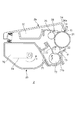
まず、画像形成装置の本体の構成について、図1を用いて説明する。図1は画像形成装置の一形態であるカラーレーザービームプリンタ)の断面図である。画像形成装置の本体100は図1に示すように、イエロー(Y)、マゼンタ(M)、シアン(C)、ブラック(Bk)各色のカートリッジ2が装着されている。上記4色のカートリッジ2は画像形成装置の本体100に対して個別に着脱可能に構成されている。さらに画像形成装置の本体100には、像担持体21上に現像されたカラー画像を転写材Pに転写する中間転写体35と、カラー画像を転写材Pに定着する定着部50と、転写材Pを排出トレイ56上に排出する排出ローラ群53,54,55を備えている。
(Image forming device body configuration)
First, the configuration of the main body of the image forming apparatus will be described with reference to FIG. FIG. 1 is a cross-sectional view of a color laser beam printer which is an embodiment of an image forming apparatus. As shown in FIG. 1, the
次に、画像形成装置の本体100の動作について説明する。まず給紙ローラ41が回転して給紙カセット7内の転写材Pを一枚分離した上で、レジストローラ44へと搬送する。一方で像担持体21と中間転写体35が、所定の外周速度V(以下プロセス速度と呼ぶ)で図1の矢印方向Sへ回転する。像担持体21は、カートリッジ2に設けられた帯電手段によって表面を均一に帯電された後、レーザ10で露光されることで静電潜像が形成される。この静電潜像は、カートリッジ2内に格納されたトナーで現像され、像担持体21上に可視像が形成される。そして、像担持体21上に現像されたY,M,C,Bkの各色のカラー画像は、中間転写体35の外周に一次転写される。中間転写体35上に転写された各色の画像は、転写材Pに二次転写された後、定着部50にて転写材Pに定着される。画像を定着された転写材Pは、排出ローラ対53,54,55を介して排出トレイ56上に排出され、画像形成動作を終了する。
Next, the operation of the
(プロセスカートリッジ構成)
本発明のカートリッジ2の構成について、図2及び図3を用いて説明する。図2はカートリッジの斜視図である。図3は、カートリッジ2の図2におけるA−A断面の概略断面図である。なお、Y,M,C,Bkの各カートリッジ2は略同一構成である。カートリッジ2は、像担持体ユニットであるクリーニングユニット2aと、現像ユニット2bに分かれている。
(Process cartridge configuration)
The configuration of the
クリーニングユニット2aは、像担持体21(回転体)、帯電ローラ23、クリーニング容器24、クリーニングブレード28、スクイシート15を有する。クリーニング容器24の開口部24bの上に重なるように、像担持体21はクリーニング容器24に回転可能に支持されている。像担持体21の周上には、像担持体21の表面を一様に帯電させるための一次帯電手段である帯電ローラ23、及び像担持体21上に残ったトナーを除去するためのクリーニングブレード28が配置されている。また、スクイシート15は、クリーニングブレード28が除去したトナーをすくい取るための可撓性シート部材であり、樹脂部材10によりクリーニング容器24に固定されている。除去された廃トナーは、クリーニング容器24に設けられた廃トナー室30(現像剤収容部)に収容される。
The
現像ユニット2bは、現像手段である現像剤担持体22(回転体)、トナーが収容されたトナー容器70(現像剤収容部)、現像容器71を有する。現像容器71の開口部71bの上に重なるように、現像剤担持体22は回転可能に現像容器71に支持されている。また現像剤担持体22の周上には、現像剤担持体22と接触して矢印Z方向に回転するトナー供給ローラ72と現像剤規制部材73、可撓性シート部材からなる吹き出し防止シート16と、吹き出し防止シート16を固定する樹脂部材11と、が配置されている。トナー容器70内には、トナー攪拌機構74が設けられている。
The developing
次に、プロセスカートリッジ2の動作について説明する。まず、トナー攪拌機構74によってトナー容器70内のトナーがトナー供給ローラ72へ搬送される。トナー供給ローラ72は、図2の矢印Z方向に回転することによって、トナーを現像剤担持体22に供給する。現像剤担持体22上に供給されたトナーは、現像剤担持体22のY方向の回転によって現像剤規制部材73へ移動する。現像剤規制部材73は、トナーを規制して所定厚さのトナー層を形成するとともに、所望の帯電電荷量を付与する。現像剤規制部材73によって形成されたトナー層は、像担持体21と現像剤担持体22とが接触した現像部に搬送された上で、現像剤担持体22に印加された現像バイアスによって像担持体21上に現像される。像担持体21上に現像されたトナーが中間転写体35に一次転写された後、像担持体上に残留した廃トナーがクリーニングブレード28によって除去され、廃トナー室30に溜められる。
Next, the operation of the
(クリーニングユニット)
本発明のクリーニングユニット2aの構成について、図4及び図5を用いてより詳細に説明する。図4は図2のI−I断面におけるクリーニングユニット2aの断面図、図5(a)はクリーニングユニット2aの一部を示す斜視図、図5(b)は図5(a)の長手方向の端部近傍における斜視図である。
(Cleaning unit)
The configuration of the
図4及び図5に示すように、像担持体21から廃トナー等の残留物を掻き落とすクリーニングブレード28と、掻き落とされた残留物をすくい取るスクイシート15がクリーニング容器24に設けられている。また、廃トナーを収容する廃トナー室30と、廃トナー室30から残留物が漏れ出ないようにクリーニングブレード28の両端部に配した像担持体端部シール部材26a,26bと、クリーニングブレード下シール27とを有している。これら各部材がクリーニング容器24に組み込まれてクリーニングユニット2aが構成されている。
As shown in FIGS. 4 and 5, a
具体的には、クリーニングブレード28及びスクイシート15は相互に干渉しない位置で像担持体21の外周面に当接している。更に、スクイシート15はクリーニング容器24に一体成形された樹脂部材10の一部が熱溶着して固定される。樹脂部材10は枠体であるクリーニング容器24に型を当接させて形成される成形空間内に、クリーニング容器24よりも弾性率の小さい熱可塑性樹脂を注入し、クリーニング容器24と一体的に成形されている。なお本実施形態では、樹脂部材10として、エラストマを用いた。
Specifically, the
また、像担持体端部シール部材26a,26bは、図5に示すようにクリーニングブレード28の長手端部、及び長手端部と連続する短手部からのトナーの漏れ出しを防止する為にその長手端部と短手端部を基準として取り付けられる。そして、像担持体端部シール部材26a,26bは、図3に示すように像担持体21の外周面と接触し、且つ、スクイシート15の長手方向Nの端部に接触している。更にクリーニングブレード下シール27によってクリーニングブレード28とクリーニング容器24の隙間等を密閉している。
Further, as shown in FIG. 5, the image carrier
(現像ユニット)
本発明の現像ユニット2bの構成について、図6及び図7を用いてより詳細に説明する。図6は図2のI−I断面における現像ユニット2bの一部を示す断面図、図7は現像ユニット2bの一部を示す斜視図である。
(Development unit)
The configuration of the developing
図6及び図7に示すように、現像剤担持体22のトナーをならす現像ブレードユニット73と、現像剤担持体22と現像容器71の間からトナーが吹き出す事を防止する吹き出し防止シート16が設けられている。また、トナーを収容する現像容器71と、現像容器71からトナーが漏れ出ないように現像ブレードユニット73の両端部に配した現像剤担持体端部シール部材95a,95bと、現像ブレード下シール93とを有している。これら各部材が現像容器71に組み込まれて現像ユニット2bが構成されている。
As shown in FIGS. 6 and 7, a developing
具体的には、現像ブレードユニット73及び吹き出し防止シート16は相互に干渉しない位置で現像剤担持体22の外周面に当接している。更に、吹き出し防止シート16は、現像容器71に一体成形された樹脂部材11の一部が熱溶着して固定される。樹脂部材10同様、樹脂部材11は枠体である現像容器71に型を当接させて形成される成形空間内に、現像容器71よりも弾性率の小さい熱可塑性樹脂を注入し、現像容器71と一体的に成形されている。なお本実施形態では、樹脂部材11として、エラストマを用いた。
Specifically, the developing
また、現像剤担持体端部シール部材95a,95bは、図6に示すように現像剤担持体22の外周面と接触し、且つ、図7に示すように現像ブレードユニット73及び吹き出し防止シート16の長手方向Nの端部に接触している。更に現像ブレード下シール93によって現像ブレードユニット73と現像容器71の隙間等を密閉している。
Further, the developer carrier
(カートリッジの再生産)
次に、カートリッジの再生産について説明する。
(Cartridge reproduction)
Next, cartridge reproduction will be described.
トナーが消費されて商品価値の喪失したカートリッジ2は、回収されて再生産工程を経て再生産される。再生産工程では、分解した部品を検査し、不合格であれば新しい部品等に適宜交換し再生産している。この時、トナーの漏れ出しを防止するシート部材にうねりが生じ、そのうねりによりトナーの漏れ出しが抑制出来ない場合、本発明に係る形態が適用される。なお、新規にカートリッジを製造する場合において、シート部材にうねりが生じ、製造したカートリッジから外部にトナー漏れが生じた場合も、本発明に係る形態を同様に適用することができる。
The
また、プロセスカートリッジ2のクリーニングユニット2aと現像ユニット2bには、それぞれにトナーを封止する為の薄板部材(シート部材)があるが、以下では、クリーニングユニット2aを再生産した場合を例にとり、説明する。したがって、以下では、現像ユニット2bについては、再生産されていないカートリッジ2と同様であるため、説明を省略し、再生産されたクリーニングユニット3aを中心に、再生産されたカートリッジの構成の説明を行う。
Further, the
(再生産されたカートリッジ)
再生産されたカートリッジの構成について、図8を用いて説明する。本実施の形態では、クリーニング手段のシール部材に本願発明の構成を適用した場合を説明する。図8(a)は再生産されたクリーニングユニットの一部を示す斜視図、図8(b)は図8(a)で示した再生産されたクリーニングユニットのシール部材近傍のB−B断面を示した図である。
(Reproduced cartridge)
The configuration of the remanufactured cartridge will be described with reference to FIG. In the present embodiment, the case where the configuration of the present invention is applied to the sealing member of the cleaning means will be described. 8A is a perspective view showing a part of the regenerated cleaning unit, and FIG. 8B is a cross-sectional view taken along the line B-B in the vicinity of the seal member of the regenerated cleaning unit shown in FIG. FIG.
再生産されたクリーニングユニット3aでは、クリーニング容器24に樹脂部材10で固定されたスクイシート15(第1の薄板部材)上に可撓性シート部材であるスクイシート17(第2の薄板部材)が接合部材18を介して固定されている。接合部材18は、長手方向に延びるようにしてスクイシート15上に形成されている。そして、短手方向Mにおいて、接合部材18は、固定面24a(座面)もしくは樹脂部材10上に少なくともその一部が設けられていればよい。なお、短手方向Mとは、長手方向Nと直交し、長手方向Nとスクイシート15を固定する際の固定面24aと平行な平面を特定する方向である。
In the regenerated cleaning unit 3a, the squeeze sheet 17 (second thin plate member), which is a flexible sheet member, is joined to the squeeze sheet 15 (first thin plate member) fixed to the cleaning
スクイシート15同様、スクイシート17はクリーニング容器24の開口部24b上に一端が突出するように配置される。このとき、図8(b)に示すように、スクイシート17の像担持体21へ向かう方向の先端位置Y2は、像担持体21へ向かう方向にスクイシート15の先端位置Y1よりも突出するように取り付けられている。本実施例では、突出量Lを0.5mmとした。
Similar to the
そして、例えば、同材料のスクイシート15,17を用いる場合にあっては、スクイシート17の厚みt2をスクイシート15の厚みt1よりも薄くすることが好ましい。本実施例では、スクイシート15の厚みをt1=0.050mm、スクイシート17の厚みをt2=0.038mmとした。しかしながら、これに限らず、スクイシート17の厚みt2をスクイシート15の厚みt1と同等以上とした場合にあっては、スクイシート17の弾性率がスクイシート15の弾性率よりも小さい材料を用いることが好ましい。この場合にあっては、厚みt1が0.050mm、弾性率が4GPaのスクイシート15と、厚みt2は、0.070mm、弾性率が3GPaのスクイシート17と、を用いることができる。
For example, when the
また本構成では、接合部材18でスクイシート17がクリーニング容器24に固定され場所が短手方向Mにおいて像担持体21からの距離が離れるにつれて、像担持体21とスクイシート17の当接圧を低くすることができる。すなわちスクイシート17は、短手方向Mにおいて、固定面24aの長さを二分する中心位置より、当接圧を高くする場合は像担持体21に近い部分、当接圧を低くする場合は像担持体21から遠い部分、を接合部材18でクリーニング容器24に固定すると良い。
In this configuration, the contact pressure between the
(効果)
上記構成とすることにより、スクイシート15にうねりが生じた場合であっても、スクイシート17により像担持体21とクリーニング容器24との間から生じるトナー漏れを抑制することができる。
(effect)
With the above configuration, even when the
また、スクイシート15に比べ、スクイシート17は、像担持体21との接触部が固定面24aから離れ、回転方向上流側に配置される。このため、スクイシート17の先端位置Y2は、スクイシート15の先端位置Y1に比べ、像担持体21に対し、突出する構成となる。この結果、像担持体21aへ当接した際の当接圧は、スクイシート15に比べ、スクイシート17を設けた場合には、高くなってしまう。この点、スクイシート17の厚さ、弾性率を変えることにより、像担持体21との当接圧を所望の大きさとすることができる。
Compared to the
さらには、短手方向Mにおける固定面24aの長さの範囲で、スクイシート17をクリーニング容器24に固定する接合部材18の配置を調整することにより、像担持体21との当接圧を調整することができる。つまり、スクイシート17の固定位置を変えることにより、容易に像担持体21との当接圧を調整することができる。
Further, the contact pressure with the
(カートリッジの再生産方法)
図8に示したクリーニングユニットの再生産方法について、以下に説明する。
(Reproduction method of cartridge)
A method for reproducing the cleaning unit shown in FIG. 8 will be described below.
始めに、クリーニングユニット2aを取り出す。なお、カートリッジ2が形成されている場合にあっては、クリーニングユニット2aと現像ユニット2bに分解し、クリーニングユニット2aを用意する。そして、クリーニングユニット2aから像担持体21を取り外す。その後、スクイシート15の表面がトナーなどで汚れている場合は、表面の清掃を行う。
First, the
次に、図9に示すように、スクイシート15上に接合部材18として両面テープ18aを貼り付ける。そして、図10に示すように、スクイシート17にうねりが生じないようにスクイシート17にテンションを掛けながら、スクイシート17を接合部材18である両面テープ上に貼り付ける。なお、本実施例ではシート引張り工具48を使って、スクイシート17に一定量のテンションを掛けながら接合部材上に貼り付けたが、これに限らず、スクイシート17にうねりが生じない方法であれば良い。
Next, as shown in FIG. 9, a double-sided tape 18 a is attached as a joining
そして、スクイシート17が取り付けられたクリーニング容器24に像担持体21を取り付け、図8に示した再生産されたクリーニングユニット3aを形成する。再生産されたクリーニングユニット3aは、現像ユニット2bと一体化されることにより、再生産されたカートリッジが完成する。
Then, the
なお、本実施例では、接合部材18として両面テープを用いたが、これに限らず、液状の接着剤など、粘着部材を接合部材18として用いても良い。また、本実施例ではスクイシート15上に接合部材18を配置した後、スクイシート17を配置したが、これに限らない。例えば、スクイシート17に接合部材18が予め固定したものを用意し、スクイシート15上に固定しても良い。
In this embodiment, the double-sided tape is used as the bonding
(効果)
上記構成により、スクイシート15を取り外すことなく、クリーニング容器24に新たなシール部材となるスクイシート17を簡便に取り付けることができる。この結果、スクイシート15の取り外し工程、スクイシート17を固定するための固定面24aを形成する工程を削減し、生産性を向上させることができる。一方で、再生産されたクリーニングユニット3aから外部へのトナー漏れをより抑制するとともに、シール部材と像担持体21との当接圧に起因した画像への影響を低減させることができる。
(effect)
With the above configuration, the
(変形例1)
実施例1では、接合部材18として両面テープを用いたが、これに限らず、熱によって溶融するホットメルト材料を用いても良い。以下では、実施例1との差異点を中心にカートリッジの再生産方法について説明を行う。
(Modification 1)
In the first embodiment, the double-sided tape is used as the joining
実施例1同様、クリーニングユニット2aを取り出し、像担持体21を取り外し、スクイシート15の表面の清掃を行う。そして、スクイシート15上にシート状のホットメルト材料を配置する。その後、シート引張り工具48を使って、スクイシート17にテンションを掛けながら、接合部材18の上にスクイシート17を仮置きする。次に、スクイシート17の表面より図11に示すようにヒートバー50を押し当て、ホットメルト材料である接合部材18を溶融させることで、スクイシート17をスクイシート15に接着する。
As in the first embodiment, the
最後に、実施例1同様、スクイシート17が取り付けられたクリーニング容器24に像担持体21が取り付け、再生産されたクリーニングユニット3aを形成する。再生産されたクリーニングユニット3aは、現像ユニット2bと一体化されることにより、再生産されたカートリッジが完成する。
Finally, as in the first embodiment, the
(効果)
上記構成により、実施例1同様の効果を得ることができる。さらには、本実施形態とすることにより、粘着部材の貼り付け工程を経ずに再生産することができるため、クリーニング容器24に対してスクイシート17の位置精度を向上させることができる。
(effect)
With the above configuration, the same effects as in the first embodiment can be obtained. Furthermore, by adopting this embodiment, it is possible to re-produce without going through the adhesive member attaching step, so that the positional accuracy of the
(変形例2)
実施例1では、接合部材18として両面テープを用いたが、これに限らず、粘着部材でなくても良い。例えば、スクイシート17とスクイシート15に溶融した際に一体化し、且つスクイシート17がレーザ光(近赤外線)を透過する材質ならば、接合部材18の代わりに、接合部材18として近赤外線吸収体を用いても良い。
以下では、実施例1との差異点を中心にカートリッジの再生産方法について説明を行う。なお、本実施例では、具体的には、スクイシート15及びスクイシート17として、近赤外線(例えば960nm)が85%透過するポリエステルを用いた。このように、同じ材質を用いることにより、溶融した際に一体化するように相溶性を有する構成としている。
(Modification 2)
In the first embodiment, the double-sided tape is used as the joining
Hereinafter, a cartridge reproduction method will be described focusing on differences from the first embodiment. In the present embodiment, specifically, polyester that transmits 85% of near infrared rays (eg, 960 nm) is used as the
実施例1同様、クリーニングユニット2aを取り出し、像担持体21を取り外し、スクイシート15の表面の清掃を行う。そして、スクイシート15上に接合部材18として近赤外線吸収体を塗布する。近赤外線吸収体としては、カーボンブラックを使用したが、近赤外線吸収体であれば、カーボンブラック以外を用いても良い。
As in the first embodiment, the
その後、シート引張り工具48を使って、スクイシート17にテンションを掛けながら、接合部材18として近赤外線吸収体が塗布されたスクイシート15の上にスクイシート17を仮置きする。次に、スクイシート17とスクイシート15を図12、図13(a)に示すように押圧治具45を用いて加圧し、レーザ照射ヘッド60より近赤外線のレーザ光eを照射する。なお、図13は、図12におけるシール部材近傍を示すE−E断面を示す図である。この時、近赤外線吸収体18cによって、吸収されたレーザ光eは熱に変換され、スクイシート15とスクイシート17の間で発熱する。そして、その熱で、スクイシート15とスクイシート17が溶融し、樹脂同士が混ざり合うことで、スクイシート15とスクイシート17が接合される。なお、近赤外線は、波長:960nm、出力20W、樹脂部材表面でのスポット径φ1.5mm)とし、長手方向Nの走査速度を速度50mm/secとした。接合部材18のスクイシート17と接する表面におけるエネルギー密度を0.22J/mm2とした。
Thereafter, the
また、本実施例では押圧治具45として、剛性を有する剛性部材46と弾性を有する弾性部材47を備える構成とした。弾性部材47を介して剛性部材46によって、クリーニング容器24に取付けられたスクイシート15に対してスクイシート17を弾性的に加圧することで、スクイシート17とスクイシート15の密着性を向上させることができる。更に、スクイシート17の位置ずれを防止することが可能になる。
In this embodiment, the pressing
具体的には、押圧治具45として、アクリルからなる剛性部材46と、厚さ5mmのシリコーンゴムからなる弾性部材47と、を一体化したものを用いた。
Specifically, as the
最後に、実施例1同様、スクイシート17が取り付けられたクリーニング容器24に像担持体21を取り付け、再生産されたクリーニングユニット3aを形成する。再生産されたクリーニングユニット3aは、現像ユニット2bと一体化されることにより、再生産されたカートリッジが完成する。
Finally, as in the first embodiment, the
なお、本実施例では、スクイシート17とスクイシート15に溶融した際に一体化する材質を用いた場合について説明した。しかし、スクイシート17とスクイシート15に溶融した際に一体化しない材質である場合にあっては、近赤外線吸収体を含有したホットメルトシ材料を接合部材18として用いることにより、本構成同様に、形成することができる。具体的には、図13(b)に示すようにスクイシート15上に接合部材18として近赤外線吸収体を塗布する代わりに、近赤外線吸収体を含有したホットメルト材料からなるシートを接合部材18としてスクイシート15上に配置する。これにより、近赤外線のレーザ光eがスクイシート17を透過し、接合部材18が溶融することにより、実施例1同様、スクイシート15上にスクイシート17を固定することができる。
In the present embodiment, the case where a material that is integrated when the
(効果)
上記構成により、実施例1同様の効果を得ることができる。さらには、本実施形態とすることにより、押圧治具45でスクイシート17をクリーニング容器24に位置決めされた状態でレーザが照射され、固定されるため、クリーニング容器24に対するスクイシート17の位置精度を向上させることができる。
(effect)
With the above configuration, the same effects as in the first embodiment can be obtained. Further, by adopting the present embodiment, the laser is irradiated and fixed in a state where the
(変形例3)
実施例1では、クリーニングユニット2aを取り出し、像担持体21を取り外し、スクイシート15の表面の清掃を行った後、短手方向Mにおいて像担持体21へ向かう方向に突出量Lを設けるようにしてスクイシート17をスクイシート15に固定した。しかしながら、これに限らず、短手方向Mにおいて、スクイシート15の像担持体21へ向かう方向の端部を除去しても良い。本構成について、図14及び図15を用いて説明を行う。図14(a)はうねりが生じたスクイシート15が像担持体21に当接している時の説明図、図14(b)は図14(a)におけるスクイシート15と像担持体21の当接部を見た上面図である。そして、図15(a)はスクイシート15を任意量除去した構成を示す斜視図、図15(b)は図15(a)におけるF−F断面図である。
(Modification 3)
In the first embodiment, the
図14に示すように、実施例1では、うねりが生じたスクイシート15が像担持体21に接触した場合、隙間Hが発生する。これにより、スクイシート15と像担持体21の当接部ではトナー層が薄くなる一方、隙間Hとなった非当接部ではトナー層が厚くなる。この結果、画像に濃度ムラが生じる恐れがあった。このため、実施例1では、像担持体21に形成されるトナー層の厚さが不均一になることを抑制するため、スクイシート17の先端位置Y2が像担持体21aへ向かう方向に、スクイシート15の先端位置Y1よりも突出するように取り付けた。
As shown in FIG. 14, in Example 1, a gap H is generated when the squeezed
これに対し、本実施例では、短手方向Mにおいて、スクイシート15の像担持体21へ向かう方向の端部を除去する工程を設ける。具体的には、クリーニングユニット2aを取り出し、像担持体21を取り外した後、短手方向Mにおいて、スクイシート15の像担持体21へ向かう方向の端部を長さUだけ切断し、除去する。なお、スクイシート15の表面の清掃する場合にあっては、スクイシート15の除去工程の前後、いずれの順番でも良い。
On the other hand, in the present embodiment, a step of removing the end portion of the
そして、接合部材18でスクイシート17をスクイシート15に接着した後、クリーニング容器24に像担持体21を取り付け、再生産されたクリーニングユニット3aを形成する。再生産されたクリーニングユニット3aは、現像ユニット2bと一体化されることにより、再生産されたカートリッジが完成する。
Then, after the
(効果)
上記構成により、実施例1同様の効果を得ることができる。さらには、本実施形態とすることにより、スクイシート17の短手方向Mにおける配置の自由度を向上させることができる。
(effect)
With the above configuration, the same effects as in the first embodiment can be obtained. Furthermore, by setting it as this embodiment, the freedom degree of arrangement | positioning in the transversal direction M of the squeeze sheet |
(実施例2)
実施例1では、クリーニングユニット2aを再生産した場合について、説明した。しかしながら、これに限らず、プロセスカートリッジ2における現像ユニット2bに本願発明を適用した構成としてもよい。以下では、実施例1と異なる構成について、再生産された現像ユニット2bを中心に、再生産されたカートリッジの構成の説明を行う。
(Example 2)
In the first embodiment, the case where the
(再生産されたカートリッジ)
再生産されたカートリッジの構成について、図16を用いて説明する。本実施の形態では、現像手段のシール部材に本願発明の構成を適用した場合を説明する。図16は、本願発明に係る形態とされた現像手段のシール部材を示す概略構成図である。
(Reproduced cartridge)
The configuration of the remanufactured cartridge will be described with reference to FIG. In the present embodiment, a case where the configuration of the present invention is applied to the seal member of the developing means will be described. FIG. 16 is a schematic configuration diagram showing a seal member of the developing means configured according to the present invention.
再生産された現像ユニット3bでは、現像容器71に樹脂部材11で固定された吹き出し防止シート16(第1の薄板部材)上に可撓性シート部材である吹き出し防止シート19(第2の薄板部材)が接合部材28を介して固定されている。接合部材28は、長手方向Nに延びるようにして吹き出し防止シート16上に形成されている。そして、短手方向Mにおいて、接合部材28は、固定面71a(座面)上に設けられていればよい。なお、短手方向Mとは、長手方向Nと直交し、長手方向Nと吹き出し防止シート16を固定する際の固定面71aと平行な平面を特定する方向である。
In the re-produced developing unit 3b, the blowout prevention sheet 19 (second thin plate member) which is a flexible sheet member on the blowout prevention sheet 16 (first thin plate member) fixed to the developing
図16(b)に示すように、吹き出し防止シート16同様、吹き出し防止シート19は現像容器71の開口部の上に一端が突出するように配置される。このとき、吹き出し防止シート19の現像剤担持体22へ向かう方向の先端位置X2は、現像剤担持体22へ向かう方向に吹き出し防止シート16の先端位置X1よりも突出するように取り付けられている。
As shown in FIG. 16B, like the
(効果)
上記構成とすることにより、吹き出し防止シート16にうねりが生じた場合であっても、吹き出し防止シート19により現像剤担持体22と現像容器71との間から生じるトナー漏れを抑制することができる。
(effect)
With the above configuration, even when the
なお、実施例1同様、現像剤担持体22へ当接した際の当接圧は、吹き出し防止シート16に比べ、吹き出し防止シート19を設けた場合には、高くなってしまう。この点、吹き出し防止シート19の厚さ、弾性率を変えることにより、像担持体21との当接圧を所望の大きさとすることができる。
As in Example 1, the contact pressure when contacting the
さらには、短手方向Mにおける固定面24aの長さの範囲で、吹き出し防止シート19を現像容器71に固定する接合部材28の配置を調整することにより、現像剤担持体22との当接圧を調整することができる。つまり、吹き出し防止シート19の固定位置を変えることにより、容易に現像剤担持体22との当接圧を調整することができる。
Further, by adjusting the arrangement of the joining
(カートリッジの再生産方法)
図16に示したクリーニングユニットの再生産方法について、以下に説明する。
(Reproduction method of cartridge)
A method for reproducing the cleaning unit shown in FIG. 16 will be described below.
始めに、現像ユニット2bを取り出す。なお、カートリッジ2が形成されている場合にあっては、クリーニングユニット2aと現像ユニット2bに分解し、現像ユニット2bを用意する。そして、現像ユニット2bから現像剤担持体22を取り外す。その後、吹き出し防止シート16の表面がトナーなどで汚れている場合は、表面の清掃を行う。
First, the developing
次に、吹き出し防止シート16上に接合部材28を介して、吹き出し防止シート19にうねりが生じないように吹き出し防止シート19にテンションを掛けながら貼り付ける。
Next, the
そして、吹き出し防止シート19が取り付けられた現像容器71に現像剤担持体22を取り付け、図16に示した再生産された現像ユニット3bを形成する。再生産された現像ユニット3bは、クリーニングユニット2aと一体化されることにより、再生産されたカートリッジが完成する。
Then, the
(効果)
上記構成により、吹き出し防止シート16を取り外すことなく、現像容器71に新たなシール部材となる吹き出し防止シート19を簡便に取り付けることができる。この結果、吹き出し防止シート16の取り外し工程、吹き出し防止シート19を固定するための固定面71aを形成する工程を削減し、生産性を向上させることができる。一方で、再生産されたクリーニングユニット3aから外部へのトナー漏れをより抑制するとともに、シール部材と現像剤担持体22との当接圧に起因した画像への影響を低減させることができる。
(effect)
With the above configuration, the
なお、実施例2においても、変形例1ないし3と同様の変更を加えることができ、これらの変更により、変形例1ないし3と同様を得ることができる。 In the second embodiment, the same changes as in the first to third modifications can be made, and the same changes as in the first to third modifications can be obtained by these changes.
2 プロセスカートリッジ
2a 像担持体ユニット
2b 現像ユニット
10,11 樹脂部材
15,17 スクイシート
16,19 吹き出し防止シート
18,28 接合部材
21 像担持体
22 現像剤担持体
23 帯電ローラ
24 クリーニング容器
26a,26b 像担持体端部シール部材
L 突出量
H 隙間
27 クリーニングブレード下シール
28 クリーニングブレード
30 廃トナー室
50 ヒートバー
70 トナー容器
71 現像容器
72 トナー供給ローラ
73 現像ブレードユニット
74 トナー攪拌機構
2
Claims (23)
現像剤を収納するための現像剤収容部と、前記現像剤収容部から外部へつながる開口部と、固定面と、を備えた枠体と、前記固定面に一端が取り付けられた第1の薄板部材であって、前記固定面に取り付けられる第1の面と、前記第1の面の反対側の第2の面と、と備える第1の薄板部材と、を備えたユニットを用意する工程と、
前記第2の面と接触するように配置された接合部材を介して、前記第1の薄板部材に第2の薄板部材を固定する工程と、
前記第2の薄板部材と当接するように、前記開口上に回転体を取り付ける工程と、
を有し、
前記回転体の回転方向において、前記第2の薄板部材は前記第1の薄板部材の上流側に位置し、前記枠体と前記回転体の間から前記現像剤が漏出することを抑制することを特徴とするカートリッジの製造方法。 A method of manufacturing a cartridge detachable from a main body of an image forming apparatus,
A developer accommodating portion for accommodating a developer, an opening leading to the outside from the developer accommodating portion, and the fixing surface, and the frame member having a first sheet having one end to said fixing surface is attached a member, a first surface attached to the fixed surface, a second surface opposite said first surface, and a first sheet metal member comprising the steps of preparing a unit with ,
Fixing the second thin plate member to the first thin plate member via a joining member arranged to contact the second surface ;
Attaching a rotating body on the opening so as to contact the second thin plate member;
I have a,
The second thin plate member is positioned on the upstream side of the first thin plate member in the rotation direction of the rotating body, and the developer is prevented from leaking between the frame body and the rotating body. A method for producing a cartridge.
ことを特徴とする請求項2に記載のカートリッジの製造方法。 3. The method according to claim 2, further comprising a step of removing at least a part of the first thin plate member so that the second thin plate member protrudes in the direction of the rotating body from the first thin plate member. A manufacturing method of the cartridge according to the description.
前記第2の薄板部材を固定する工程は、前記レーザ光を照射する工程である
ことを特徴とする請求項1ないし4のいずれか1項に記載のカートリッジの製造方法。 The joining member is formed of a material that absorbs laser light, and the second thin plate member is formed of a material that transmits the laser light,
The method of manufacturing a cartridge according to any one of claims 1 to 4, wherein the step of fixing the second thin plate member is a step of irradiating the laser beam.
前記枠体は、前記像担持体から除去された現像剤を収容するクリーニング容器であり、前記第1の薄板部材と前記第2の薄板部材は、前記像担持体に当接する可撓性シート部材であることを特徴とする請求項1ないし10のいずれか1項に記載のカートリッジの製造方法。 The rotating body is an image carrier,
The frame body is a cleaning container that accommodates the developer removed from the image carrier, and the first thin plate member and the second thin plate member are flexible sheet members that contact the image carrier. cartridge method according to any one of claims 1 to 10, characterized in that.
前記枠体は、前記現像剤担持体に現像剤を供給する現像容器であり、
前記第1の薄板部材と前記第2の薄板部材は、前記現像剤担持体に当接する可撓性シート部材であることを特徴とする請求項1ないし10のいずれか1項に記載のカートリッジの製造方法。 The rotating body is a developer carrier;
The frame is a developing container for supplying a developer to the developer carrying member;
The first sheet metal member and the second sheet metal member, the cartridge according to any one of claims 1 to 10, wherein said a flexible sheet member abutting the developer carrying member Production method.
現像剤を収納するための現像剤収容部と、前記現像剤収容部から外部へつながる開口部と、固定面と、を備えた枠体と、
前記現像剤収容部の開口部上において前記枠体に対して回転可能となるように前記枠体に支持された回転体と、
前記固定面に一端が取り付けられた第1の薄板部材であって、前記固定面に取り付けられた第1の面と、前記第1の面の反対側の第2の面と、を有する第1の薄板部材と、
前記第2の面と接触するように配置された接合部材と、
前記第1の薄板部材に前記接合部材を介して固定され、前記回転体に当接する第2の薄板部材と、
を有し、
前記回転体の回転方向において、前記第2の薄板部材は前記第1の薄板部材の上流側に位置し、前記枠体と前記回転体の間から前記現像剤が漏出することを抑制することを特徴とするカートリッジ。 A cartridge that is detachable from the main body of the image forming apparatus,
A developer accommodating portion for accommodating a developer, an opening leading to the outside from the developer accommodating portion, and the frame having a fixing surface, a
A rotating body supported by the frame body so as to be rotatable with respect to the frame body on the opening of the developer container;
A first thin plate member having one end attached to the fixed surface , the first thin plate member having a first surface attached to the fixed surface, and a second surface opposite to the first surface. A thin plate member ,
A joining member arranged to contact the second surface ;
Is fixed through the joint member to the first sheet metal member, and a second sheet metal member which abuts on the rotary body,
I have a,
The second thin plate member is positioned on the upstream side of the first thin plate member in the rotation direction of the rotating body, and the developer is prevented from leaking between the frame body and the rotating body. Features cartridge.
前記第2の薄板部材は、前記レーザ光を透過する材質で形成されたものである
ことを特徴とする請求項13ないし15のいずれか1項に記載のカートリッジ。 The joining member is formed of a material that absorbs laser light,
The cartridge according to any one of claims 13 to 15 , wherein the second thin plate member is formed of a material that transmits the laser light.
前記枠体は、前記像担持体から除去された現像剤を収容するクリーニング容器であり、前記第1の薄板部材と前記第2の薄板部材は、前記像担持体に当接する可撓性シート部材であることを特徴とする請求項13ないし21のいずれか1項に記載のカートリッジ。 The rotating body is an image carrier,
The frame body is a cleaning container that accommodates the developer removed from the image carrier, and the first thin plate member and the second thin plate member are flexible sheet members that contact the image carrier. The cartridge according to claim 13 , wherein the cartridge is a cartridge.
前記枠体は、前記現像剤担持体に現像剤を供給する現像容器であり、
前記第1の薄板部材と前記第2の薄板部材は、前記現像剤担持体に当接する可撓性シート部材であることを特徴とする請求項13ないし21のいずれか1項に記載のカートリッジ。 The rotating body is a developer carrier;
The frame is a developing container for supplying a developer to the developer carrying member;
The cartridge according to any one of claims 13 to 21 , wherein the first thin plate member and the second thin plate member are flexible sheet members in contact with the developer carrier.
Priority Applications (2)
| Application Number | Priority Date | Filing Date | Title |
|---|---|---|---|
| JP2014157756A JP6406916B2 (en) | 2014-08-01 | 2014-08-01 | Cartridge and cartridge manufacturing method |
| US14/810,247 US10386744B2 (en) | 2014-08-01 | 2015-07-27 | Cartridge and method for manufacturing cartridge |
Applications Claiming Priority (1)
| Application Number | Priority Date | Filing Date | Title |
|---|---|---|---|
| JP2014157756A JP6406916B2 (en) | 2014-08-01 | 2014-08-01 | Cartridge and cartridge manufacturing method |
Publications (3)
| Publication Number | Publication Date |
|---|---|
| JP2016035496A JP2016035496A (en) | 2016-03-17 |
| JP2016035496A5 JP2016035496A5 (en) | 2017-09-07 |
| JP6406916B2 true JP6406916B2 (en) | 2018-10-17 |
Family
ID=55179936
Family Applications (1)
| Application Number | Title | Priority Date | Filing Date |
|---|---|---|---|
| JP2014157756A Active JP6406916B2 (en) | 2014-08-01 | 2014-08-01 | Cartridge and cartridge manufacturing method |
Country Status (2)
| Country | Link |
|---|---|
| US (1) | US10386744B2 (en) |
| JP (1) | JP6406916B2 (en) |
Family Cites Families (5)
| Publication number | Priority date | Publication date | Assignee | Title |
|---|---|---|---|---|
| JPS60170880A (en) * | 1984-02-15 | 1985-09-04 | Konishiroku Photo Ind Co Ltd | Toner guide plate |
| JPH0883031A (en) * | 1994-09-12 | 1996-03-26 | Canon Inc | Cleaner for image forming device |
| JP3188439B1 (en) * | 2000-03-07 | 2001-07-16 | キヤノン株式会社 | Reproduction method of process cartridge |
| JP2007171818A (en) * | 2005-12-26 | 2007-07-05 | Canon Inc | Process cartridge and method for manufacturing process cartridge |
| JP5738153B2 (en) * | 2011-11-09 | 2015-06-17 | キヤノン株式会社 | Process cartridge and image forming apparatus |
-
2014
- 2014-08-01 JP JP2014157756A patent/JP6406916B2/en active Active
-
2015
- 2015-07-27 US US14/810,247 patent/US10386744B2/en active Active
Also Published As
| Publication number | Publication date |
|---|---|
| US10386744B2 (en) | 2019-08-20 |
| US20160033932A1 (en) | 2016-02-04 |
| JP2016035496A (en) | 2016-03-17 |
Similar Documents
| Publication | Publication Date | Title |
|---|---|---|
| JP5980064B2 (en) | Development device manufacturing method and process cartridge manufacturing method | |
| JP6274892B2 (en) | Developer container, cartridge, image forming apparatus | |
| US7127192B2 (en) | Developing frame and process cartridge | |
| US9377716B2 (en) | Unit and image forming apparatus | |
| KR101634467B1 (en) | Developer cartridge unit and image forming apparatus | |
| US6501924B2 (en) | Method of manufacturing developer container, method of manufacturing process cartridge, developer container and process cartridge | |
| JP5489883B2 (en) | cartridge | |
| JP6469135B2 (en) | Cartridge, unit and manufacturing method thereof | |
| JP4545877B2 (en) | DEVELOPING FRAME, METHOD FOR WELDING AND USE THEREOF, PROCESS CARTRIDGE, AND IMAGE FORMING DEVICE | |
| JP6016579B2 (en) | unit | |
| JP6406916B2 (en) | Cartridge and cartridge manufacturing method | |
| JP2004126003A (en) | Developing unit, process cartridge and image forming apparatus | |
| JP5738153B2 (en) | Process cartridge and image forming apparatus | |
| JP5858767B2 (en) | Cartridge, cartridge manufacturing method, and image forming apparatus | |
| US10656589B2 (en) | Manufacturing method for cartridge attachable to image forming apparatus and cartridge | |
| JP4981346B2 (en) | Developing device, process cartridge, and electrophotographic image forming apparatus | |
| JP6425465B2 (en) | Cartridge and method of manufacturing cartridge | |
| US10996589B2 (en) | Method for disassembling developing device and method for recycling developing device | |
| JP5858766B2 (en) | Cartridge, cartridge manufacturing method, and image forming apparatus | |
| JP2004101669A (en) | Developing apparatus and electrophotographic image forming apparatus | |
| JP2004101671A (en) | Developing apparatus, electrophotographic image forming apparatus, and bushing member |
Legal Events
| Date | Code | Title | Description |
|---|---|---|---|
| A521 | Request for written amendment filed |
Free format text: JAPANESE INTERMEDIATE CODE: A523 Effective date: 20170731 |
|
| A621 | Written request for application examination |
Free format text: JAPANESE INTERMEDIATE CODE: A621 Effective date: 20170731 |
|
| A977 | Report on retrieval |
Free format text: JAPANESE INTERMEDIATE CODE: A971007 Effective date: 20180309 |
|
| A131 | Notification of reasons for refusal |
Free format text: JAPANESE INTERMEDIATE CODE: A131 Effective date: 20180320 |
|
| A521 | Request for written amendment filed |
Free format text: JAPANESE INTERMEDIATE CODE: A523 Effective date: 20180514 |
|
| TRDD | Decision of grant or rejection written | ||
| A01 | Written decision to grant a patent or to grant a registration (utility model) |
Free format text: JAPANESE INTERMEDIATE CODE: A01 Effective date: 20180821 |
|
| A61 | First payment of annual fees (during grant procedure) |
Free format text: JAPANESE INTERMEDIATE CODE: A61 Effective date: 20180918 |
|
| R151 | Written notification of patent or utility model registration |
Ref document number: 6406916 Country of ref document: JP Free format text: JAPANESE INTERMEDIATE CODE: R151 |