JP6382101B2 - Method for manufacturing absorbent article - Google Patents
Method for manufacturing absorbent article Download PDFInfo
- Publication number
- JP6382101B2 JP6382101B2 JP2014266457A JP2014266457A JP6382101B2 JP 6382101 B2 JP6382101 B2 JP 6382101B2 JP 2014266457 A JP2014266457 A JP 2014266457A JP 2014266457 A JP2014266457 A JP 2014266457A JP 6382101 B2 JP6382101 B2 JP 6382101B2
- Authority
- JP
- Japan
- Prior art keywords
- sheet
- elastic member
- absorbent article
- leak
- transport direction
- Prior art date
- Legal status (The legal status is an assumption and is not a legal conclusion. Google has not performed a legal analysis and makes no representation as to the accuracy of the status listed.)
- Active
Links
Images


Landscapes
- Absorbent Articles And Supports Therefor (AREA)
Description
本発明は、使い捨ておむつ等の吸収性物品の一部の領域に弾性部材を配置する吸収性物品の製造方法に関する。 The present invention relates to a method for manufacturing an absorbent article in which an elastic member is disposed in a partial region of an absorbent article such as a disposable diaper.
特許文献1には、吸収性物品の一部の領域である脚周り開口部の近傍のみに弾性部材を配置する使い捨ておむつの製造方法が開示されている。特許文献1の使い捨ておむつの製造方法は、使い捨ておむつの表面シート及び裏面シートのうち一方を構成する第1ウェブを連続した状態で搬送し、第1ウェブの脚周り開口部近傍に弾性部材を貼付するための接着剤を塗布する。弾性部材を連続した状態で前後方向に伸長させ、伸長状態の弾性部材を第1ウェブ上に配置する。そして、表面シートと裏面シートのうち他方を構成する第2ウェブを、第1ウェブ及び弾性部材に貼付する。
これにより、第1ウェブ、第2ウェブ、及びこれらのウェブ間に配置された弾性部材が連続した連続体が製造される。次いで、吸収性物品の幅方向に沿って個々の製品長さ毎に連続体を切断する。これにより、伸長状態であった弾性部材は、前後方向に収縮し、接着剤によって脚周り開口部近傍に貼付された部分のみ残る。よって、脚周り開口部近傍のみに弾性部材を設けることができる。 Thereby, the 1st web, the 2nd web, and the continuous body with which the elastic member arrange | positioned between these webs continued was manufactured. Subsequently, a continuous body is cut | disconnected for every individual product length along the width direction of an absorbent article. As a result, the elastic member in the stretched state contracts in the front-rear direction, and only the portion pasted around the leg opening by the adhesive remains. Therefore, the elastic member can be provided only in the vicinity of the leg opening.
しかし、上述の吸収性物品の製造方法は、以下の問題があった。弾性部材の切断時に2枚のウェブを共に切断するため、切断機構の負荷が高く、切断機構の摩耗が生じ易かった。 However, the manufacturing method of the above-mentioned absorbent article has the following problems. Since the two webs are cut together when the elastic member is cut, the load on the cutting mechanism is high and the cutting mechanism is easily worn.
本願は、このような問題に鑑みてなされたものであり、切断機構の摩耗を抑制しつつ、吸収性物品の一部の領域に弾性部材を配置する吸収性物品の製造方法を提供することを目的とする。 This application is made in view of such a problem, and provides the manufacturing method of the absorbent article which arrange | positions an elastic member in the one part area | region of an absorbent article, suppressing abrasion of a cutting mechanism. Objective.
本開示に係る吸収性物品の製造方法は、吸収性物品を構成する構成部材が連続した第1シート(外装シート連続体22W)を搬送する第1シート搬送工程(外装シート搬送工程S1)と、前記第1シート上に、前記搬送方向に連続する弾性部材(内側弾性部材連続体72W)を前記搬送方向に伸長した状態で配置する弾性部材配置工程(内側弾性部材配置工程S2)と、前記第1シート上の前記弾性部材の一部を覆うように、前記搬送方向に間隔を空けて第2シート(防漏シート21)を配置する第2シート配置工程(防漏シート配置工程S3)と、前記第2シートと前記第2シートの間に位置する前記弾性部材を、前記第1シート側に押圧しつつ切断する弾性部材切断工程(内側弾性部材切断工程S4)と、を有することを要旨とする。
The manufacturing method of the absorbent article according to the present disclosure includes a first sheet conveying step (exterior sheet conveying step S1) for conveying a first sheet (exterior sheet
本開示に係る吸収性物品の製造方法によれば、切断機構の摩耗を抑制しつつ、吸収性物品の一部の領域に弾性部材を配置する吸収性物品の製造方法を提供できる。 According to the method for manufacturing an absorbent article according to the present disclosure, it is possible to provide a method for manufacturing an absorbent article in which an elastic member is disposed in a partial region of the absorbent article while suppressing wear of the cutting mechanism.
以下において、本発明に係る吸収性物品の製造装置について、図面を参照しながら説明する。具体的には、(1)吸収性物品の構成、(2)吸収性物品の製造方法、(3)第2シート配置工程、(4)作用・効果、(5)変形例に係る吸収性物品の製造方法、(6)その他の実施形態について説明する。 Below, the manufacturing apparatus of the absorbent article which concerns on this invention is demonstrated, referring drawings. Specifically, (1) composition of absorbent article, (2) manufacturing method of absorbent article, (3) second sheet placement step, (4) action / effect, (5) absorbent article according to modification (6) Other embodiments will be described.
なお、以下の図面の記載において、同一または類似の部分には、同一または類似の符号を付している。ただし、図面は模式的なものであり、各寸法の比率などは現実のものとは異なることに留意すべきである。したがって、具体的な寸法などは以下の説明を参酌して判断すべきものである。また、図面相互間においても互いの寸法の関係や比率が異なる部分が含まれていることは勿論である。 In the following description of the drawings, the same or similar parts are denoted by the same or similar reference numerals. However, it should be noted that the drawings are schematic and ratios of dimensions and the like are different from actual ones. Accordingly, specific dimensions and the like should be determined in consideration of the following description. Moreover, it is a matter of course that portions having different dimensional relationships and ratios are included between the drawings.
(1)吸収性物品の構成
まず、本実施形態に係る吸収性物品1の構成について、図面を参照しながら説明する。図1は、本実施形態に係る吸収性物品1を示す平面図である。図2は、図1に示すA−A断面図である。図3は、図1に示すB−B断面図である。図4は、図1に示すC−C断面図である。本実施形態では、吸収性物品1は、オープン型の使い捨ておむつである。
(1) Configuration of Absorbent Article First, the configuration of the
本実施形態において、オープン型のおむつとは、予めパンツ型に成形されたおむつではなく、使用前の状態において展開された状態になっており、製品の所定部分同士を止着テープなどで留めることによって使用者に装着するおむつをいう。 In this embodiment, an open-type diaper is not a diaper that has been molded into a pants shape in advance, but is in a state of being unfolded in a state before use, and fastening predetermined portions of the product with fastening tape or the like. Refers to a diaper worn by the user.
本実施形態に係る使い捨ておむつ1は、互いに直交する前後方向L及び幅方向Wを有している。また、使い捨ておむつ1は、前後方向L及び幅方向Wに直交する厚み方向Tを有する。厚み方向は、着用者側に位置する肌対向面側T1と、非肌対向面側T2と、を有する。
The
吸収性物品1は、吸収性物品1の前後方向Lにおいて、着用者の前胴周りに対応する前胴周り領域R1と、着用者の後胴周りに対応する後胴周り領域R2と、着用者の股下に対応し、前胴周り領域R1と後胴周り領域R2との間に位置する股下領域R3と、を有する。股下領域R3は、吸収体30の前後方向の中央において吸収体30が幅方向の内側に括れた領域である。
The
吸収性物品1は、肌面シート10と、非肌面シート20と、吸収体30と、脚周り弾性部材71と、内側弾性部材72と、腰周り弾性部材73と、を有する。
The
肌面シート10は、吸収体30の肌対向面側T1に位置する。肌面シート10は、吸収体を覆う表面シート11と、表面シート11の幅方向の外側端部を覆うサイドシート12と、を有する。サイドシート12は、表面シート11の幅方向の外側端部に接合されている。サイドシート12の幅方向の内側端部は、前後方向に沿って折り目を起点に幅方向の外側に折り返され、サイドシート12間には、起立性の防漏ギャザーを構成する防漏弾性部材74が配置されている。なお、図2〜図4の断面図では、表面シート11とサイドシート12を接合する接着剤を省略している。
The
表面シート11は、不織布や織布や有孔プラスチックシートやメッシュシート等、液体を透過する構造のシート状の材料であれば、特に限定されない。これらの材料を構成する繊維は、ポリエチレン(PE)やポリプロピレン(PP)やポリエチレンテレフタレート(PET)等の単繊維や、ポリエチレン及びポリプロピレンをグラフト重合してなる繊維や、芯鞘構造等の複合繊維等が挙げられる。サイドシート12は、表面シート11と同様の材料によって構成することができる。但し、サイドシート12は、表面シート11と比べて体液を透過しにくいように構成されている。
The
非肌面シート20は、防漏シート21と、外装シート22と、を有する。防漏シート21は、吸収体30の非肌対向面側T2に位置する。防漏シート21は、液不透過性で、かつ、透湿又は非透湿性のフィルムからなる。防漏シート21の前後方向Lの外側端部は、吸収性物品1の前後方向Lの外側端部よりも前後方向Lの内側に位置する。具体的には、防漏シート21の前端縁21Fは、吸収性物品1の前端縁1Fよりも後側に位置し、防漏シート21の後端縁21Rは、吸収性物品1の後端縁1Rよりも後側に位置する。防漏シート21の前後方向の長さは、吸収性物品1の前後方向Lの長さよりも短い。
The
外装シート22は、防漏シート21の非肌対向面側T2に位置する。外装シート22は、防水性の不織布シートである。外装シート22と肌面シート10は、吸収性物品1の外縁において接合されている。吸収性物品1の外縁とは、吸収性物品1の前端縁1F、吸収性物品1の後端縁1R、吸収性物品1の外側縁を含む。
The
吸収体30は、コアラップと、液体を吸収する吸収性コアとを有する。吸収性コアは、親水性繊維、高吸収性ポリマーを含む。親水性繊維の例としては、粉砕パルプ、コットン等のセルロース、レーヨン、フィブリルレーヨン等の再生セルロース、アセテート、トリアセテート等の半合成セルロース、粒子状ポリマー、繊維状ポリマー、熱可塑性疎水性化学繊維、又は、親水化処理を施した熱可塑性疎水性化学繊維等を単独又は混合して用いることができる。これらの中でも、低コストと吸収体の成形し易さとを考慮すると、粉砕パルプを使用することが好ましい。親水性繊維に高分子吸収体を混合したものを使用してもよい。
The
なお、吸収性コアは、コアラップによって包まれている。例えば、コアラップとしては、少なくとも肌面当接面側の一部に透透過性を有する各種の繊維不織布若しくはティッシュシート、具体的には、目付が10〜30g/m2のエアスルー繊維不織布やスパンボンド不織布やSMS不織布やティッシュシートを用いることができる。 The absorbent core is wrapped with a core wrap. For example, as the core wrap, various fiber nonwoven fabrics or tissue sheets having permeability at least at a part on the skin contact surface side, specifically, air-through fiber nonwoven fabric or spunbond having a basis weight of 10 to 30 g / m 2 Nonwoven fabrics, SMS nonwoven fabrics, and tissue sheets can be used.
一対の脚周り弾性部材71は、吸収体30の最大幅の位置よりも幅方向Wの外側に配置されている。脚周り弾性部材71は、厚み方向Tにおいて防漏シート21に重なる。脚周り弾性部材71は、前後方向Lに伸縮可能に構成されている。脚周り弾性部材71は、糸状のゴムからなる。脚周り弾性部材71の有効長の範囲71Eは、脚周り弾性部材71が前後方向Lに伸縮可能な状態で配置されている範囲である。脚周り弾性部材71は、防漏シート21と肌面シート10の間に配置されている。
The pair of leg-around
一対の内側弾性部材72は、吸収体30の最大幅の位置よりも幅方向Wの外側、かつ脚周り弾性部材71よりも幅方向Wの内側に配置されている。内側弾性部材72は、厚み方向Tにおいて防漏シート21に重なる。内側弾性部材72は、前後方向Lに伸縮可能に構成されている。脚周り弾性部材71は、糸状のゴムからなる。内側弾性部材72の有効長の範囲72Eは、前後方向Lに伸縮可能な状態で配置されている範囲である。内側弾性部材72は、防漏シート21と外装シート22との間に配置されている。内側弾性部材72の有効長の範囲72Eは、防漏シート21と厚み方向において重なっている。更に、内側弾性部材72の前後方向Lの外側端部は、防漏シート21の前後方向の外側端部よりも前後方向Lの内側に位置する。
The pair of inner
内側弾性部材72から前側に延びる前側領域FA及び内側弾性部材72から後側に延びる後側領域RAにおいて、肌面シート10と外装シート22は、接合されている。図1に、内側弾性部材72から前側に延びる前側領域FAと、内側弾性部材から後側に延びる後側領域RAと、に斜線を付して示す。より詳細には、前側領域FAのうち防漏シートの前端縁21Fよりも前側の領域において、肌面シート10と外装シート22は、接合されている。後側領域RAのうち防漏シートの後端縁21Rよりも後側の領域において、肌面シート10と外装シート22は、接合されている。
In the front area FA extending forward from the inner
また、前側領域FA及び後側領域RAの少なくともいずれか一方の肌面シート10又は外装シート22には、肌面シート10又は外装シート22を厚み方向Tに貫通した開口が形成されている。本実施の形態では、後側領域RAの外装シート22に開口22Aが形成されている。外装シート22の開口22Aは、防漏シート21の後端縁21Rよりも後側に位置する。外装シート22の開口22Aは、腰周り弾性部材73によって覆われている。外装シート22の開口22Aは、内側弾性部材72の前後方向Lにおける延長線上に位置する。
In addition, an opening penetrating the
腰周り弾性部材73は、吸収体30の後端縁よりも後側、かつ吸収性物品1の後端縁1Rよりも前側に配置されている。腰周り弾性部材73の一部は、厚み方向Tにおいて防漏シート21に重なる。腰周り弾性部材73は、幅方向Wに収縮可能に構成されている。腰周り弾性部材73は、伸縮性シートからなる。腰周り弾性部材73は、防漏シート21と肌面シート10の間、又は外装シート22と肌面シート10の間に配置されている。
The waist
腰周り弾性部材73は、防漏シート21の後端縁21Rを覆う被覆シートを構成する。また、腰周り弾性部材73は、外装シート22の開口22Aを覆うように配置されている。
The waist
本実施形態に係る吸収性物品1では、脚周り弾性部材71及び内側弾性部材72は、幅方向Wにおいて吸収体30と重ならない領域に配置されている。なお、内側弾性部材72は、幅方向Wにおいて吸収体30と重なる領域に配置されていてもよい。本実施形態に係る吸収性物品1では、前後方向Lにおいて、脚周り弾性部材71の有効長の範囲71Eは、内側弾性部材72の有効長の範囲72Eよりも長くなるように構成されている。
In the
吸収性物品1には、着用者の脚周りに配置される脚周り開口部41が形成されている。脚周り開口部41は、少なくとも股下領域R3に設けられている。脚周り開口部41は、吸収性物品の外縁が幅方向の内側に括れた形状である。
The
使い捨ておむつの後胴周り領域R2には、ファスニングテープ90が設けられている。ファスニングテープ90は、一対であって、後胴周り領域R2において、幅方向Wに沿って延び、前胴周り領域R1の非肌対向面に設けられたターゲット部95に止着されることにより、吸収性物品1を着用者の身体に保持する。ファスニングテープ90は、面ファスナーや粘着テープなどによって形成される。幅方向Wにおける一対のファスニングテープ90間には、腰周り弾性部材73が設けられている。腰周り弾性部材73は、ファスニングテープ90間を幅方向に収縮する。ターゲット部95は、ファスニングテープ90が止着可能に構成されている。ターゲット部95は、不織布によって形成される。
A
(2)吸収性物品の製造方法
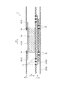
次に、本実施形態に係る吸収性物品の製造方法の一例について説明する。図5は、吸収性物品の製造方法を説明するための図である。図5は、吸収性物品の平面視における吸収性物品の製造工程を模式的に示している。なお、本実施の形態において説明しない方法については、既存の方法を用いることができる。また、以下に説明する製造方法は、一例であり、他の製造方法によって製造することもできる。
(2) Manufacturing method of absorbent article Next, an example of the manufacturing method of the absorbent article which concerns on this embodiment is demonstrated. FIG. 5 is a diagram for explaining a method of manufacturing an absorbent article. FIG. 5 schematically shows a manufacturing process of the absorbent article in a plan view of the absorbent article. Note that an existing method can be used as a method not described in this embodiment. Moreover, the manufacturing method demonstrated below is an example and can also be manufactured with another manufacturing method.
吸収性物品の製造方法は、外装シート搬送工程(第1シート搬送工程)S1と、内側弾性部材配置工程(弾性部材配置工程)S2と、防漏シート配置工程(第2シート配置工程)S3と、内側弾性部材切断工程(弾性部材切断工程)S4と、接着剤塗布工程S5と、脚周り弾性部材配置工程S6と、腰周り弾性部材配置工程(第3シート配置工程)S7と、構成部材配置工程S8と、脚周り形成工程S9と、連続体切断工程S10と、を少なくとも含む。 The manufacturing method of the absorbent article includes an exterior sheet conveying step (first sheet conveying step) S1, an inner elastic member arranging step (elastic member arranging step) S2, and a leak-proof sheet arranging step (second sheet arranging step) S3. , Inner elastic member cutting step (elastic member cutting step) S4, adhesive application step S5, leg elastic member arrangement step S6, waist elastic member arrangement step (third sheet arrangement step) S7, and component arrangement It includes at least a step S8, a leg circumference forming step S9, and a continuum cutting step S10.
外装シート搬送工程(第1シート搬送工程)S1は、吸収性物品1を構成する構成部材としての外装シート22が連続した外装シート連続体22Wを搬送する。外装シート連続体22Wは、外装シート22が前後方向Lに連続したシートである。外装シート連続体22Wの搬送方向MDは、外装シート22の前後方向Lに沿っている。
Exterior sheet conveyance process (1st sheet conveyance process) S1 conveys
内側弾性部材配置工程(弾性部材配置工程)S2は、外装シート搬送工程S1の後工程である。内側弾性部材配置工程S2は、外装シート連続体22W上に、内側弾性部材72が搬送方向MDに連続した内側弾性部材連続体72Wを搬送方向MDに伸長した状態で配置する。内側弾性部材連続体72Wは、内側弾性部材72が前後方向Lに連続した弾性部材である。内側弾性部材連続体72Wには、内側弾性部材72の有効長の範囲72Eにおいて接着剤が塗布されている。図5において、接着剤が塗布された領域の内側弾性部材連続体72Wを実線で示し、接着剤が塗布されていない領域の内側弾性部材連続体72Wを点線で示す。内側弾性部材連続体72Wは、接着剤が塗布された領域において外装シート連続体22Wに接着される。外装シート連続体22Wに接着された内側弾性部材連続体72Wの領域は、内側弾性部材72の有効長の範囲72Eとなる。
The inner elastic member arranging step (elastic member arranging step) S2 is a subsequent step of the exterior sheet conveying step S1. Inner elastic member arrangement | positioning process S2 arrange | positions in the state which the inner side elastic member
防漏シート配置工程(第2シート配置工程)S3は、外装シート連続体22W上の内側弾性部材連続体72Wの一部を覆うように、第2シートとしての防漏シート21を配置する。防漏シート配置工程S3は、搬送方向MDに間隔を空けて防漏シート21を配置する。防漏シート21は、第2シートを構成する。防漏シート21は、内側弾性部材72の有効長の範囲72Eを覆うように配置される。このとき、防漏シート21の外装シート連続体22W側の面には、予め接着剤が塗布されている。
In the leakage preventing sheet arranging step (second sheet arranging step) S3, the
図5のS3において、防漏シート21に接着剤が塗布された接着領域A1を斜線で示す。防漏シート21に接着剤が塗布された接着領域A1は、内側弾性部材72が配置された領域に設けられてなく、内側弾性部材72よりも幅方向外側と、内側弾性部材72よりも幅方向の内側と、に設けられている。内側弾性部材72よりも幅方向の外側に位置する接着領域A1は、防漏シート21の幅方向の外側端部よりも内側に位置する。内側弾性部材72よりも幅方向の外側に位置する接着領域A1と防漏シート21の幅方向の外側端部との距離は、5mm〜7.5mmであることが好ましい。当該構成によれば、防漏シート21の幅方向の外側端部から接着剤がにじみ出ることを防止できる。なお、防漏シート21に接着剤を塗布する代わりに、外装シート連続体22Wに接着剤を塗布してもよい。
In S <b> 3 of FIG. 5, the adhesion area A <b> 1 where the adhesive is applied to the leak-
内側弾性部材切断工程(弾性部材切断工程)S4は、防漏シート配置工程S3の後工程である。防漏シート21と防漏シート21の間に位置する(防漏シート21によって覆われていない)内側弾性部材連続体72Wを、外装シート連続体22W側に押圧しつつ切断する。本実施の形態では、内側弾性部材切断工程S4において、内側弾性部材連続体72Wと、外装シート連続体22Wと、を切断する。
The inner elastic member cutting step (elastic member cutting step) S4 is a subsequent step of the leakproof sheet arranging step S3. The inner elastic member
内側弾性部材連続体72Wと外装シート連続体22Wとを切断することにより、内側弾性部材72は、搬送方向MDに収縮し、内側弾性部材72の有効長の範囲72Eのみ伸縮可能な状態となる。内側弾性部材72の前後方向Lの外側端部(有効長の前後方向の外側)は、防漏シート21と外装シート22に接合されず、防漏シート21と外装シート22の間に収縮状態で配置される。防漏シート21と外装シート22に接合されていない内側弾性部材72を図5において点線で示す。また、外装シート連続体22Wが切断されることにより、外装シート連続体22Wに開口22Aが形成される。開口22Aは、搬送方向MDに対して傾斜する方向に延びる。開口22Aが搬送方向MDに対して傾斜する方向に延びるため、外装シート連続体22Wの搬送中に開口が大きく開くことを抑制できる。
By cutting the inner elastic member
接着剤塗布工程S5は、外装シート連続体22W及び防漏シート21上に接着剤を塗布する。より、詳細には、防漏シート21の肌対向面と、外装シート連続体22Wにおいて防漏シート21に覆われてない領域の肌対向面と、に接着剤を塗布する。図5のS5において、外装シート連続体22W及び防漏シート21に接着剤が塗布された接着領域A2を斜線で示す。外装シート連続体22W及び防漏シート21に接着剤が塗布された接着領域A2は、脚周り弾性部材配置工程S6において脚周り弾性部材71が配置される領域に設けられてなく、脚周り弾性部材71が配置される領域の幅方向の外側と、内側弾性部材72が配置された領域の幅方向の内側と、に設けられている。
In the adhesive application step S <b> 5, an adhesive is applied on the exterior sheet
脚周り弾性部材配置工程S6は、接着剤塗布工程S5の後工程である。脚周り弾性部材配置工程S6は、外装シート連続体22W及び防漏シート21上に、脚周り弾性部材連続体71Wを搬送方向MDに伸長した状態で配置する。脚周り弾性部材連続体71Wは、脚周り弾性部材71が搬送方向MDに連続した弾性部材である。脚周り弾性部材連続体71Wには、脚周り弾性部材71の有効長の範囲71Eにおいて接着剤が塗布されている。接着剤が塗布された領域の脚周り弾性部材連続体71Wを実線で示し、接着剤が塗布されていない領域の脚周り弾性部材連続体71Wを破線で示す。脚周り弾性部材連続体71Wは、接着剤が塗布された領域において、外装シート連続体22W及び防漏シート21に接着されている。外装シート連続体22W及び防漏シート21に接着された領域は、脚周り弾性部材71の有効長の範囲71Eとなる。
Leg elastic member arrangement process S6 is a post process of adhesive application process S5. In the leg-around elastic member arrangement step S6, the leg-around elastic member
腰周り弾性部材配置工程(第3シート配置工程)S7は、脚周り弾性部材配置工程S6の後工程である。腰周り弾性部材配置工程S7は、内側弾性部材切断工程S4における切断位置を覆う腰周り弾性部材73を配置する。腰周り弾性部材73は、第3シートを構成する。腰周り弾性部材配置工程S6は、搬送方向MDに間隔を空けて腰周り弾性部材73を配置する。腰周り弾性部材73は、外装シート連続体22Wの開口22Aを覆うように配置される。
The waist elastic member placement step (third sheet placement step) S7 is a post-step of the leg elastic member placement step S6. In the waist elastic member arrangement step S7, the waist
腰周り弾性部材73は、接着剤塗布工程S5において塗布された接着剤によって、外装シート連続体22W及び防漏シート21に接着される。内側弾性部材切断工程S4における切断位置は、接着剤塗布工程S5において接着剤が塗布されている。よって、切断位置において、腰周り弾性部材73は、外装シート連続体22W及び防漏シート21に接着される。
The waist
構成部材配置工程S8は、少なくとも接着剤塗布工程S5の後工程である。吸収性物品を構成する構成部材としての吸収体30、ファスニングテープ90等を配置するとともに、肌面シート10を構成する肌面シート連続体10Wを搬送方向MDに連続して供給する。これにより、吸収性物品が搬送方向に連続した吸収性物品連続体が形成される。
The constituent member arranging step S8 is at least a subsequent step of the adhesive application step S5. While arrange | positioning the
脚周り形成工程S9(図示せず)は、構成部材配置工程S8の後工程であり、脚周り開口部41に沿って吸収性物品連続体を切断して、脚周り開口部41を形成する。
The leg circumference forming step S9 (not shown) is a subsequent process of the component member arranging step S8, and the absorbent article continuous body is cut along the leg circumference opening 41 to form the
連続体切断工程S10は、吸収性物品の幅方向に沿って吸収性物品連続体を切断する。これにより、個々の吸収性物品を得ることができる。 In the continuous body cutting step S10, the absorbent article continuous body is cut along the width direction of the absorbent article. Thereby, each absorbent article can be obtained.
(3)防漏シート配置工程
次いで、防漏シート配置工程S3について詳細に説明する。図6は、防漏シート配置工程S3を説明するための図である。なお、説明の便宜上、外装シート連続体、防漏シート、及びウエスト弾性部材以外の構成部材については、図6において省略する。
(3) Leak-proof sheet arrangement | positioning process Then, leak-proof sheet arrangement | positioning process S3 is demonstrated in detail. FIG. 6 is a diagram for explaining the leak-proof sheet arranging step S3. For convenience of explanation, constituent members other than the exterior sheet continuum, the leak-proof sheet, and the waist elastic member are omitted in FIG.
防漏シート配置工程S3は、第1シートとしての外装シート連続体22W上に第2シートとしての防漏シート21を載せた状態で、一対のロール間に外装シート連続体22Wと防漏シート21を通過させて、外装シート連続体22Wと防漏シート21を接合する。一対のロールは、少なくとも防漏シート21の幅方向の全域を押圧できるように構成されている。具体的には、一対のロールの直交方向CDの長さは、防漏シート21の直交方向CDの長さよりも長く構成されている。
In the leakage preventing sheet arrangement step S3, the exterior sheet
一対のロールは、防漏シート21が配置された領域では、防漏シート21、内側弾性部材連続体72W、及び外装シート連続体22Wを押圧し、防漏シート21が配置されていない領域(搬送方向における防漏シート21と防漏シート21の間の領域)は、内側弾性部材連続体72W及び非肌面シートを押圧する。
In the region where the leak-
防漏シート配置工程S3では、防漏シート21間において防漏シート21によって覆われていない内側弾性部材連続体72Wの少なくとも一部を押圧しなくてもよい。具体的には、一対のロールによって、防漏シート21の搬送方向MDの先端21Cと、防漏シート21の先端21Cから搬送方向下流側に延出する内側弾性部材連続体72Wと、を押圧する。図6において、一対のロールによって押圧する領域に斜線を付して示す。一方、一対のロールによって、防漏シート21の搬送方向MDの後端21Pと、この防漏シート21の後端21Pから搬送方向上流側に延出する内側弾性部材連続体72Wと、を押圧しない。
In the leakage preventing sheet arranging step S3, it is not necessary to press at least a part of the inner elastic member
また、防漏シート配置工程S3は、防漏シート21を外装シート連続体22W上に配置する際に、防漏シート21の搬送方向MDの後端21Pに対して空気を噴射し、防漏シート21の搬送方向の後端21Pを外装シート連続体22W側に向けて送出してもよい。空気の噴射は、少なくとも防漏シート21の搬送方向の後端21Pが外装シート連続体22W側に向かうように噴射すればよく、防漏シート21の搬送方向MDの全体が外装シート連続体22W側に向かうように噴射してもよい。
Further, in the leakage preventing sheet arranging step S3, when the
また、防漏シート配置工程S3は、防漏シート21において内側弾性部材連続体72Wと重なる領域を押さず、防漏シート21において内側弾性部材連続体72Wと重ならない領域のみを、外装シート連続体22W側に押圧してもよい。防漏シート21において内側弾性部材連続体72Wと重なる領域とは、防漏シート21が配置された領域のうち、内側弾性部材連続体72Wが配置されている領域である。具体的には、一対のロールに、外周面に対して凹む凹部を周方向に連続して形成し、防漏シート21において内側弾性部材連続体72Wと重なる領域に当該凹部が当たるように配置することができる。凹部は、外周面に対して凹んでいるため、凹部に対向する領域(防漏シートにおいて内側弾性部材連続体と重なる領域)は、一対のロールによって押圧されない。
In addition, the leakage preventing sheet arrangement step S3 does not push the region overlapping the inner
(4)作用・効果
本実施の形態に係る吸収性物品の製造方法は、第2シート(防漏シート21)によって覆われていない弾性部材(内側弾性部材72)を切断するため、第1シート(外装シート)と第2シート(防漏シート)に挟まれた弾性部材(内側弾性部材72)を切断する構成と比較して、切断機構の負荷を抑制できる。よって、切断機能の刃の摩耗を抑制できる。更に、吸収性物品の製造方法は、第2シート(防漏シート21)間に位置する弾性部材(内側弾性部材72)を第1シート(外装シート)側に押圧しつつ切断する。弾性部材(内側弾性部材72)を切断機構によって直接切断することが可能となる。
(4) Action / Effect The manufacturing method of the absorbent article according to the present embodiment cuts the elastic member (inner elastic member 72) that is not covered by the second sheet (leakproof sheet 21). Compared with the structure which cut | disconnects the elastic member (inner elastic member 72) pinched | interposed between the (exterior sheet) and the second sheet (leakproof sheet), the load on the cutting mechanism can be suppressed. Therefore, abrasion of the cutting function blade can be suppressed. Furthermore, the manufacturing method of an absorbent article cut | disconnects, pressing the elastic member (inner elastic member 72) located between 2nd sheets (leak-proof sheet 21) to the 1st sheet | seat (exterior sheet | seat) side. The elastic member (inner elastic member 72) can be directly cut by the cutting mechanism.
吸収性物品の製造方法は、弾性部材切断工程(内側弾性部材切断工程)における切断位置を覆う第3シート(腰周り弾性部材73)を配置する第3シート配置工程(腰周り弾性部材配置工程)を備えていてもよい。弾性部材(内側弾性部材)の切断時に第1シート(外装シート)が切断され、開口が形成されることがある。第1シート(外装シート)の切断位置を第3シート(腰周り弾性部材)によって覆うことにより、第1シート(外装シート)が切断された場合においても、第1シート(外装シート)の開口を塞ぐことができる。 The manufacturing method of an absorbent article includes a third sheet placement step (waist waist elastic member placement step) in which a third sheet (waist waist elastic member 73) covering the cutting position in the elastic member cutting step (inner elastic member cutting step) is placed. May be provided. When the elastic member (inner elastic member) is cut, the first sheet (exterior sheet) may be cut to form an opening. Even when the first sheet (exterior sheet) is cut by covering the cutting position of the first sheet (exterior sheet) with the third sheet (waist elastic member), the opening of the first sheet (exterior sheet) is opened. Can be closed.
また、第1シートの切断箇所を塞がない場合、製造工程で第1シートにテンションがかかると、切断箇所が開いて、開口が大きくなってしまう場合がある。しかし、第1シートの切断箇所を塞ぐことにより、開口が大きくなることを防ぐことができる。第3シート配置工程(腰周り弾性部材配置工程)は、製造工程で第1シートにテンションが大きくかかる工程の前であることが好ましい。例えば、第3シート配置工程(腰周り弾性部材配置工程)は、脚周り形成工程S9の前であることが好ましい。また、第3シート配置工程(腰周り弾性部材配置工程)は、弾性部材切断工程(内側弾性部材切断工程)S4のすぐ後の工程であることが、より好ましい。 In addition, when the cut portion of the first sheet is not blocked, if the first sheet is tensioned in the manufacturing process, the cut portion may open and the opening may become large. However, it is possible to prevent the opening from becoming large by closing the cut portion of the first sheet. The third sheet placement step (waist elastic member placement step) is preferably before the step in which a large tension is applied to the first sheet in the manufacturing process. For example, it is preferable that the third sheet arrangement step (waist circumference elastic member arrangement step) is before the leg circumference formation step S9. Moreover, it is more preferable that the third sheet arranging step (waist elastic member arranging step) is a step immediately after the elastic member cutting step (inner elastic member cutting step) S4.
内側弾性部材連続体において接着剤が塗布された領域は、第2シート(防漏シート)の搬送方向の両端部よりも搬送方向の内側に位置していてもよい。内側弾性部材連続体を切断した際に、接着剤が塗布されていない内側弾性部材の領域は、収縮する。接着剤が塗布された内側弾性部材の領域が第2シート(防漏シート)の搬送方向の両端部よりも搬送方向の内側に位置するため、接着剤が塗布されていない内側弾性部材の領域が第2シート(防漏シート)に重なり易くなる。換言すると、切断された状態の内側弾性部材の両端部が、防漏シートの搬送方向の両端部よりも搬送方向の内側に位置するようにできる。そのため、固定されていない内側弾性部材の両端が露出されずに安定して搬送することができる。 The area | region where the adhesive agent was apply | coated in the inner side elastic member continuous body may be located inside the conveyance direction rather than the both ends of the conveyance direction of a 2nd sheet | seat (leakproof sheet). When the inner elastic member continuous body is cut, the region of the inner elastic member to which the adhesive is not applied contracts. Since the area | region of the inner side elastic member to which the adhesive agent was apply | coated is located inside the conveyance direction rather than the both ends of the conveyance direction of a 2nd sheet | seat (leakproof sheet), the area | region of the inner side elastic member to which the adhesive agent was not apply | coated It becomes easy to overlap the second sheet (leakproof sheet). In other words, the both ends of the cut inner elastic member can be positioned more inside in the conveyance direction than both ends in the conveyance direction of the leak-proof sheet. Therefore, both ends of the inner elastic member that is not fixed can be stably conveyed without being exposed.
第2シート配置工程(防漏シート配置工程)は、一対のロール間に第1シートと第2シートを通過させ、第2シート間において第2シートによって覆われていない弾性部材の少なくとも一部を押圧しなくてもよい。第2シート間の弾性部材は、第2シートによって覆われてなく、露出している。当該弾性部材に接着剤が付されてしまうことがあり、この接着剤によってロールと弾性部材が付き、弾性部材がロールに巻き込まれてしまうことがある。特に、露出している弾性部材を連続して押圧すると、弾性部材の巻き込みが生じ易い。弾性部材を連続的に押圧しないことにより、巻き込みを抑制出来る。 In the second sheet arranging step (leakproof sheet arranging step), the first sheet and the second sheet are passed between the pair of rolls, and at least a part of the elastic member that is not covered by the second sheet is interposed between the second sheets. It is not necessary to press. The elastic member between the second sheets is not covered by the second sheet but exposed. An adhesive may be attached to the elastic member, and the adhesive and the roll may be attached to the elastic member, and the elastic member may be caught in the roll. In particular, when the exposed elastic member is continuously pressed, the elastic member is likely to be caught. Entanglement can be suppressed by not pressing the elastic member continuously.
また、第2シート配置工程(防漏シート配置工程)において、第2シート(防漏シート21)の搬送方向の先端を押圧し、かつ第2シートの搬送方向の先端から搬送方向下流側に延出する内側弾性部材連続体72Wを押圧するように構成してもよい。第2シートの搬送方向の先端を押圧することにより、第2シートの搬送方向の先端を第1シートに止着できる。また、搬送方向下流側に延出する内側弾性部材連続体から第2シートの搬送方向の先端にかけて押圧することで、確実に先端を第1シートに止着できる。第2シートの搬送方向の先端から搬送方向下流側に延出する内側弾性部材連続体は、比較的接着剤が付されてしまう可能性が少ない。よって、第2シートの搬送方向の先端から搬送方向下流側に延出する内側弾性部材連続体を押圧した場合に、ロールに接着剤が付着するおそれが少ない。よって、弾性部材の巻き込みを抑制しつつ、第2シートの搬送方向の先端を確実に第1シートに止着できる。
Further, in the second sheet arranging step (leakproof sheet arranging step), the leading end of the second sheet (leakproof sheet 21) in the conveying direction is pressed and extended from the leading end in the conveying direction of the second sheet to the downstream side in the conveying direction. You may comprise so that the inner side elastic member
また、第2シート配置工程(防漏シート配置工程)において、第2シートの搬送方向の後端から搬送方向上流側に延出する内側弾性部材連続体を押圧しないように構成されていてもよい。第2シートの搬送方向の後端から搬送方向上流側に延出する内側弾性部材連続体は、接着剤を塗布しない領域ではあるが、接着剤が塗布された領域に近いため、接着剤が残ってしまう可能性が比較的ある。第2シートの搬送方向の後端から搬送方向上流側に延出する内側弾性部材連続体を押圧しないことにより、ロールに接着剤が付着することを防止できる。そのため、ロールに弾性部材やシートが巻き込まれてしまうことを抑制できる。 Further, in the second sheet arrangement step (leakproof sheet arrangement step), the inner elastic member continuous body extending from the rear end in the conveyance direction of the second sheet to the upstream side in the conveyance direction may not be pressed. . The inner elastic member continuum extending from the rear end of the second sheet in the conveyance direction to the upstream side in the conveyance direction is an area where the adhesive is not applied, but is close to the area where the adhesive is applied, so that the adhesive remains. There is a relative possibility. By not pressing the inner elastic member continuous body extending from the rear end of the second sheet in the conveyance direction to the upstream side in the conveyance direction, it is possible to prevent the adhesive from adhering to the roll. Therefore, it can suppress that an elastic member and a sheet are caught in a roll.
第2シート配置工程(防漏シート配置工程)は、第2シートの搬送方向の後端に対して空気を噴射し、前記第2シートの搬送方向の後端を前記第1シート側に向けて送出してもよい。第2シートの搬送方向の後端を押圧せずに、第2シートの搬送方向の後端を空気によって第1シート側に導くことができる。 In the second sheet arrangement step (leakproof sheet arrangement step), air is jetted toward the rear end in the conveyance direction of the second sheet, and the rear end in the conveyance direction of the second sheet is directed to the first sheet side. It may be sent out. The rear end in the transport direction of the second sheet can be guided to the first sheet side by air without pressing the rear end in the transport direction of the second sheet.
第2シート配置工程(防漏シート配置工程)は、前記第2シートにおいて弾性部材と重なる領域を押さず、前記第2シートにおいて弾性部材と重ならない領域のみを第1シート側に押圧してもよい。例えば、内側弾性部材連続体に接着剤を塗布する構成にあっては、内側弾性部材連続体を過度に押圧すると、接着剤が意図しない領域にしみ出すことがある。しかし、内側弾性部材連続体を押圧しないことにより、周囲の第2シートを適切に押圧しつつ、接着剤が意図しない領域にしみ出すことを抑制できる。 In the second sheet arrangement step (leakproof sheet arrangement step), even if the region that does not overlap the elastic member in the second sheet is not pressed, only the region that does not overlap the elastic member in the second sheet is pressed to the first sheet side. Good. For example, in the configuration in which the adhesive is applied to the inner elastic member continuum, if the inner elastic member continuum is excessively pressed, the adhesive may ooze out to an unintended region. However, by not pressing the inner elastic member continuous body, it is possible to prevent the adhesive from seeping into an unintended region while appropriately pressing the surrounding second sheet.
(5)変形例に係る吸収性物品の製造方法
図7は、変形例に係る吸収性物品の製造方法を説明するための図である。変形例に係る吸収性物品の製造方法は、パンツ型の吸収性物品を製造する方法である。なお、以下の説明において、上述の実施形態と同様の構成については、同符号を用いて説明を省略する。
(5) Manufacturing method of absorbent article according to modification FIG. 7 is a diagram for explaining a manufacturing method of an absorbent article according to the modification. The manufacturing method of the absorbent article which concerns on a modification is a method of manufacturing an underpants type absorbent article. In the following description, the same components as those in the above-described embodiment are denoted by the same reference numerals and the description thereof is omitted.
変形例に係る吸収性物品の製造方法は、吸収性物品の前胴周り領域R1を構成する前側外装シートと前側外装シートの肌対向面側に位置する防漏シートとの間に、腰周り弾性部材75を配置するとともに、吸収性物品の後胴周り領域を構成する後側外装シートと後側外装シートの肌対向面側T1に位置する防漏シート21との間に、腰周り弾性部材75を配置する。
The method for manufacturing an absorbent article according to the modified example includes a waist elastic between a front exterior sheet constituting the front waistline region R1 of the absorbent article and a leak-proof sheet positioned on the skin facing surface side of the front exterior sheet. The
前側外装シートと後側外装シートは、吸収性物品1の幅方向Wにおいて連続して配置される。一方、防漏シート21は、吸収性物品の幅方向Wにおいて間隔を空けて配置される。
The front exterior sheet and the rear exterior sheet are continuously disposed in the width direction W of the
第1シート搬送工程S101として、前側外装シートが連続した前側外装シート連続体221Wを搬送し、後側外装シートが連続した後側外装シート連続体222Wを搬送する。前側外装シート連続体221W及び後側外装シート連続体222Wは、第1シートを構成する。
As 1st sheet conveyance process S101, the front side exterior sheet
次いで、弾性部材配置工程S102として、前側外装シート連続体221W上に腰周り弾性部材75が搬送方向MDに連続した腰周り弾性部材連続体75Wを搬送方向に伸長した状態で配置し、後側外装シート連続体222W上に腰周り弾性部材連続体75Wを搬送方向に伸長した状態で配置する。
Next, as the elastic member arranging step S102, the waist
次いで、第2シート配置工程S103として、前側外装シート連続体221W上の腰周り弾性部材連続体75Wの一部を覆うように、搬送方向に間隔を空けて防漏シート21を配置し、後側外装シート連続体222W上の腰周り弾性部材連続体75Wの一部を覆うように、搬送方向に間隔を空けて防漏シート21を配置する。防漏シート21は、第2シートを構成する。
Next, as the second sheet arrangement step S103, the leak-
次いで、弾性部材切断工程S104として、防漏シート21と防漏シート21の間に位置する腰周り弾性部材連続体75Wを前側外装シート連続体221W側に押圧しつつ切断し、防漏シート21と防漏シート21の間に位置する腰周り弾性部材連続体75Wを後側外装シート連続体222W側に押圧しつつ切断する。腰周り弾性部材連続体75Wが切断されることによって、腰周り弾性部材75が収縮し、防漏シート21が配置された領域内に配置される。また、弾性部材切断工程S104において、前側外装シート連続体221Wに開口221Aが形成され、後側外装シート連続体222Wに開口222Aが形成される。
Next, as an elastic member cutting step S104, the waist
次いで、第3シート配置工程S107として、弾性部材切断工程S104における切断位置を覆う吸収性本体を配置する。吸収性本体80は、吸収体と、吸収体の非肌対向面側に位置する吸収体裏面シートと、を少なくとも有する。なお、図7において、吸収体を省略して示す。吸収性本体80の吸収体裏面シートは、第3シートを構成する。吸収性本体80によって、前側外装シート連続体221Wの開口221A、及び後側外装シート連続体222Wの開口222Aを覆うことができる。
Next, as the third sheet arranging step S107, an absorbent main body that covers the cutting position in the elastic member cutting step S104 is arranged. The absorptive
変形例に係る吸収性物品の製造方法によっても、第2シート(防漏シート21)によって覆われていない弾性部材(腰周り弾性部材75)を切断するため、切断機構の負荷を抑制でき、切断機能の刃の摩耗を抑制できる。更に、吸収性物品の製造方法は、第2シート(防漏シート21)間に位置する弾性部材(腰周り弾性部材75)を第1シート(前側外装シート連続体221W、後側外装シート連続体222W)側に押圧しつつ切断し、弾性部材(腰周り弾性部材75)を切断機構によって直接切断することが可能となる。
Also by the manufacturing method of the absorbent article which concerns on a modification, in order to cut | disconnect the elastic member (waist waist elastic member 75) which is not covered with the 2nd sheet | seat (leakproof sheet 21), the load of a cutting mechanism can be suppressed and cutting It can suppress the function blade wear. Further, the manufacturing method of the absorbent article includes the elastic member (waist waist elastic member 75) positioned between the second sheets (leak-proof sheet 21) as the first sheet (front
(6)その他の実施形態
本実施の形態の吸収性物品は、使い捨ておむつであるが、吸収性物品は、当該構成に限定されない。吸収性物品は、生理用ナプキンであってもよいし、吸収パッド、パンティライナーであってもよい。
(6) Other embodiment Although the absorbent article of this Embodiment is a disposable diaper, an absorbent article is not limited to the said structure. The absorbent article may be a sanitary napkin, an absorbent pad, or a panty liner.
また、上述の実施形態では、内側弾性部材を外装シート連続体に接合するための接着剤は、内側弾性部材にされている。しかし、他の変形例において、内側弾性部材を外装シート連続体に接合するための接着剤は、外装シート連続体に塗布されていてもよいし、防漏シートに塗布されていてもよい。 Moreover, in the above-mentioned embodiment, the adhesive agent for joining an inner side elastic member to an exterior sheet | seat continuous body is made into the inner side elastic member. However, in another modified example, the adhesive for joining the inner elastic member to the exterior sheet continuum may be applied to the exterior sheet continuum or may be applied to the leak-proof sheet.
また、本実施の形態では、内側弾性部材72の有効長の範囲72Eが防漏シートに重なるように構成している。しかし、他の変形例において、脚周り弾性部材71の有効長の範囲71Eが防漏シート21に重なるように構成してもよい。脚周り弾性部材71の有効長の範囲71Eが防漏シート21に重なる構成にあっては、脚周り弾性部材71から前側に延びる前側領域及び脚周り弾性部材71から後側に延びる後側領域において、肌面シートと外装シートを接合でき、吸収性物品の外縁において開口する領域を少なくできる。
In the present embodiment, the
他の変形例において、防漏シートの前端縁を覆う被覆シートを設けてもよい。よって、被覆シートは、防漏シートの前端縁と前記防漏シートの後端縁のうち少なくとも一方を覆うように構成されていればよく、防漏シートの前端縁と前記防漏シートの後端縁の両方を覆うように構成してもよい。 In another modification, a covering sheet that covers the front end edge of the leak-proof sheet may be provided. Therefore, the covering sheet only needs to be configured to cover at least one of the front end edge of the leak-proof sheet and the rear end edge of the leak-proof sheet, and the front end edge of the leak-proof sheet and the rear end of the leak-proof sheet You may comprise so that both edges may be covered.
前側領域の肌面シート又は外装シートに開口が形成される構成にあっては、防漏シートの前端縁を覆う被覆シートによって開口を覆うように構成してもよい。防漏シートの前端縁を覆う被覆シートとしては、ターゲット部を構成するシートを例示できる。 In the configuration in which the opening is formed in the skin sheet or the exterior sheet in the front region, the opening may be covered with a covering sheet that covers the front edge of the leak-proof sheet. Examples of the covering sheet that covers the front edge of the leak-proof sheet include a sheet that constitutes the target portion.
以上、上述の実施形態を用いて本発明について詳細に説明したが、当業者にとっては、本発明が本明細書中に説明した実施形態に限定されるものではないということは明らかである。本発明は、特許請求の範囲の記載により定まる本発明の趣旨及び範囲を逸脱することなく修正及び変更態様として実施することができる。従って、本明細書の記載は、例示説明を目的とするものであり、本発明に対して何ら制限的な意味を有するものではない。 Although the present invention has been described in detail using the above-described embodiments, it is obvious to those skilled in the art that the present invention is not limited to the embodiments described in this specification. The present invention can be implemented as modified and changed modes without departing from the spirit and scope of the present invention defined by the description of the scope of claims. Therefore, the description of the present specification is for illustrative purposes and does not have any limiting meaning to the present invention.
1 :吸収性物品
10 :肌面シート
11 :表面シート
12 :サイドシート
20 :非肌面シート
21 :防漏シート
22 :外装シート
30 :吸収体
41 :脚周り開口部
71 :脚周り弾性部材
72 :内側弾性部材
73 :腰周り弾性部材
74 :防漏弾性部材
L :前後方向
W :幅方向
T :厚み方向
S1 :外装シート搬送工程(第1シート搬送工程)
S2 :内側弾性部材配置工程(弾性部材配置工程)
S3 :防漏シート配置工程(第2シート配置工程)
S4 :内側弾性部材切断工程(弾性部材切断工程)
S5 :接着剤塗布工程
S6 :脚周り弾性部材配置工程
S7 :腰周り弾性部材配置工程(第3シート配置工程)
S8 :構成部材配置工程
S9 :脚周り形成工程
S10 :連続体切断工程
1: Absorbent article 10: Skin sheet 11: Top sheet 12: Side sheet 20: Non-skin sheet 21: Leak-proof sheet 22: Exterior sheet 30: Absorbent body 41: Leg opening 71: Leg elastic member 72 : Inner elastic member 73: waist elastic member 74: leak-proof elastic member L: longitudinal direction W: width direction T: thickness direction S1: exterior sheet conveying step (first sheet conveying step)
S2: Inner elastic member placement step (elastic member placement step)
S3: Leakproof sheet arrangement process (second sheet arrangement process)
S4: Inner elastic member cutting step (elastic member cutting step)
S5: Adhesive application step S6: Leg elastic member arrangement step S7: Hip elastic member arrangement step (third sheet arrangement step)
S8: Component member arranging step S9: Leg circumference forming step S10: Continuous body cutting step
Claims (5)
前記第1シート上に、搬送方向に連続する弾性部材を前記搬送方向に伸長した状態で配置する弾性部材配置工程と、
前記第1シート上の前記弾性部材の一部を覆うように、前記搬送方向に間隔を空けて第2シートを配置する第2シート配置工程と、
前記第2シートと前記第2シートの間に位置する前記弾性部材を、前記第1シート側に押圧しつつ切断する弾性部材切断工程と、を有し、
前記第2シート配置工程は、一対のロール間に前記第1シートと前記第2シートを通過させ、前記第2シート間において前記第2シートによって覆われていない弾性部材の少なくとも一部を押圧せずに、前記第2シートを前記第1シート側に押圧する、吸収性物品の製造方法。 A first sheet conveying step of conveying a first sheet in which constituent members constituting the absorbent article are continuous;
On the first sheet, an elastic member disposing step of disposing an elastic member continuous in the transport direction in an extended state in the transport direction;
A second sheet disposing step of disposing a second sheet at an interval in the transport direction so as to cover a part of the elastic member on the first sheet;
An elastic member cutting step of cutting the elastic member positioned between the second sheet and the second sheet while pressing the elastic member toward the first sheet,
In the second sheet arranging step, the first sheet and the second sheet are passed between a pair of rolls, and at least a part of the elastic member not covered by the second sheet is pressed between the second sheets. Without manufacturing , the said 2nd sheet | seat is pressed to the said 1st sheet | seat side, The manufacturing method of an absorbent article.
前記第1シート上に、搬送方向に連続する弾性部材を前記搬送方向に伸長した状態で配置する弾性部材配置工程と、 On the first sheet, an elastic member disposing step of disposing an elastic member continuous in the transport direction in an extended state in the transport direction;
前記第1シート上の前記弾性部材の一部を覆うように、前記搬送方向に間隔を空けて第2シートを配置する第2シート配置工程と、 A second sheet disposing step of disposing a second sheet at an interval in the transport direction so as to cover a part of the elastic member on the first sheet;
前記第2シートと前記第2シートの間に位置する前記弾性部材を、前記第1シート側に押圧しつつ切断する弾性部材切断工程と、を有し、 An elastic member cutting step of cutting the elastic member positioned between the second sheet and the second sheet while pressing the elastic member toward the first sheet,
前記第2シート配置工程は、前記第2シートの搬送方向の後端に対して空気を噴射し、前記第2シートの搬送方向の後端を前記第1シート側に向けて送出する、吸収性物品の製造方法。 In the second sheet arrangement step, absorptivity is formed by injecting air toward the rear end of the second sheet in the transport direction and sending the rear end of the second sheet in the transport direction toward the first sheet. Article manufacturing method.
前記第1シート上に、搬送方向に連続する弾性部材を前記搬送方向に伸長した状態で配置する弾性部材配置工程と、 On the first sheet, an elastic member disposing step of disposing an elastic member continuous in the transport direction in an extended state in the transport direction;
前記第1シート上の前記弾性部材の一部を覆うように、前記搬送方向に間隔を空けて第2シートを配置する第2シート配置工程と、 A second sheet disposing step of disposing a second sheet at an interval in the transport direction so as to cover a part of the elastic member on the first sheet;
前記第2シートと前記第2シートの間に位置する前記弾性部材を、前記第1シート側に押圧しつつ切断する弾性部材切断工程と、を有し、 An elastic member cutting step of cutting the elastic member positioned between the second sheet and the second sheet while pressing the elastic member toward the first sheet,
前記第2シート配置工程は、前記第2シートにおいて前記弾性部材と重なる領域を押さず、前記第2シートにおいて前記弾性部材と重ならない領域のみを第1シート側に押圧する、吸収性物品の製造方法。 In the manufacturing of an absorbent article, the second sheet arranging step does not press a region overlapping the elastic member in the second sheet, and presses only a region not overlapping the elastic member in the second sheet toward the first sheet. Method.
前記接着剤が付された接着領域は、前記第2シートの搬送方向の両端部よりも搬送方向の内側に位置する、請求項1から請求項4のいずれか1項に記載の吸収性物品の製造方法。 An adhesive that joins the elastic member is applied to the first sheet or the elastic member,
The absorptive article according to any one of claims 1 to 4 , wherein the adhesive region to which the adhesive is attached is located on the inner side in the conveyance direction than both ends in the conveyance direction of the second sheet. Production method.
Priority Applications (1)
| Application Number | Priority Date | Filing Date | Title |
|---|---|---|---|
| JP2014266457A JP6382101B2 (en) | 2014-12-26 | 2014-12-26 | Method for manufacturing absorbent article |
Applications Claiming Priority (1)
| Application Number | Priority Date | Filing Date | Title |
|---|---|---|---|
| JP2014266457A JP6382101B2 (en) | 2014-12-26 | 2014-12-26 | Method for manufacturing absorbent article |
Publications (2)
| Publication Number | Publication Date |
|---|---|
| JP2016123609A JP2016123609A (en) | 2016-07-11 |
| JP6382101B2 true JP6382101B2 (en) | 2018-08-29 |
Family
ID=56358398
Family Applications (1)
| Application Number | Title | Priority Date | Filing Date |
|---|---|---|---|
| JP2014266457A Active JP6382101B2 (en) | 2014-12-26 | 2014-12-26 | Method for manufacturing absorbent article |
Country Status (1)
| Country | Link |
|---|---|
| JP (1) | JP6382101B2 (en) |
Family Cites Families (4)
| Publication number | Priority date | Publication date | Assignee | Title |
|---|---|---|---|---|
| JP3756492B2 (en) * | 2002-08-22 | 2006-03-15 | 株式会社瑞光 | Wearing article manufacturing method and manufacturing apparatus |
| JP5728907B2 (en) * | 2010-11-30 | 2015-06-03 | 王子ホールディングス株式会社 | Method for manufacturing absorbent article |
| JP5971153B2 (en) * | 2013-02-28 | 2016-08-17 | 王子ホールディングス株式会社 | Disposable diaper manufacturing method |
| JP6212289B2 (en) * | 2013-06-04 | 2017-10-11 | ユニ・チャーム株式会社 | Disposable diapers |
-
2014
- 2014-12-26 JP JP2014266457A patent/JP6382101B2/en active Active
Also Published As
| Publication number | Publication date |
|---|---|
| JP2016123609A (en) | 2016-07-11 |
Similar Documents
| Publication | Publication Date | Title |
|---|---|---|
| US9220639B2 (en) | Boxer shorts formed by a method which does not require removal of material from the manufacturing web | |
| CN103200914B (en) | The method of absorbent commodity and manufacture absorbent commodity | |
| CN106456384B (en) | Manufacturing method of stretchable elastic member and disposable diaper using the elastic member | |
| CN104507434B (en) | wearing items | |
| US9186279B2 (en) | Disposable diaper | |
| CN103582471B (en) | Absorbent article | |
| JP5977590B2 (en) | Absorbent article and method for manufacturing absorbent article | |
| JP5495823B2 (en) | Method for manufacturing absorbent article | |
| CN104427962B (en) | Wearing article | |
| US20120238989A1 (en) | Disposable diaper | |
| KR20160052654A (en) | Individually packaged absorbent article | |
| WO2020075348A1 (en) | Disposable diaper | |
| JP2020501737A (en) | Absorbent articles | |
| WO2020075349A1 (en) | Disposable diaper | |
| CN113382703B (en) | Absorbent article | |
| JP2014217413A (en) | Method for manufacturing absorbent article and absorbent article | |
| JP4917366B2 (en) | Disposable diapers | |
| JP6382101B2 (en) | Method for manufacturing absorbent article | |
| JP7141285B2 (en) | Pants-type disposable diaper | |
| JP6382102B2 (en) | Absorbent articles | |
| JP5958298B2 (en) | Method and apparatus for manufacturing disposable diapers | |
| JP4758821B2 (en) | Method for producing disposable absorbent article | |
| JP5993591B2 (en) | Disposable diaper manufacturing method | |
| JP5186331B2 (en) | Absorbent articles | |
| WO2011008139A1 (en) | Boxer shorts formed by a method which does not require removal of material from the manufacturing web |
Legal Events
| Date | Code | Title | Description |
|---|---|---|---|
| A621 | Written request for application examination |
Free format text: JAPANESE INTERMEDIATE CODE: A621 Effective date: 20170622 |
|
| A977 | Report on retrieval |
Free format text: JAPANESE INTERMEDIATE CODE: A971007 Effective date: 20180323 |
|
| A131 | Notification of reasons for refusal |
Free format text: JAPANESE INTERMEDIATE CODE: A131 Effective date: 20180403 |
|
| A521 | Request for written amendment filed |
Free format text: JAPANESE INTERMEDIATE CODE: A523 Effective date: 20180601 |
|
| TRDD | Decision of grant or rejection written | ||
| A01 | Written decision to grant a patent or to grant a registration (utility model) |
Free format text: JAPANESE INTERMEDIATE CODE: A01 Effective date: 20180703 |
|
| A61 | First payment of annual fees (during grant procedure) |
Free format text: JAPANESE INTERMEDIATE CODE: A61 Effective date: 20180801 |
|
| R150 | Certificate of patent or registration of utility model |
Ref document number: 6382101 Country of ref document: JP Free format text: JAPANESE INTERMEDIATE CODE: R150 |
|
| R250 | Receipt of annual fees |
Free format text: JAPANESE INTERMEDIATE CODE: R250 |
|
| R250 | Receipt of annual fees |
Free format text: JAPANESE INTERMEDIATE CODE: R250 |
|
| R250 | Receipt of annual fees |
Free format text: JAPANESE INTERMEDIATE CODE: R250 |
|
| R250 | Receipt of annual fees |
Free format text: JAPANESE INTERMEDIATE CODE: R250 |