JP6325680B2 - Wireless communication device - Google Patents
Wireless communication device Download PDFInfo
- Publication number
- JP6325680B2 JP6325680B2 JP2016551913A JP2016551913A JP6325680B2 JP 6325680 B2 JP6325680 B2 JP 6325680B2 JP 2016551913 A JP2016551913 A JP 2016551913A JP 2016551913 A JP2016551913 A JP 2016551913A JP 6325680 B2 JP6325680 B2 JP 6325680B2
- Authority
- JP
- Japan
- Prior art keywords
- frame
- information
- access point
- frames
- wireless terminal
- Prior art date
- Legal status (The legal status is an assumption and is not a legal conclusion. Google has not performed a legal analysis and makes no representation as to the accuracy of the status listed.)
- Active
Links
- 238000004891 communication Methods 0.000 title claims description 193
- 230000005540 biological transmission Effects 0.000 claims description 208
- 230000004044 response Effects 0.000 claims description 74
- 238000012790 confirmation Methods 0.000 claims description 25
- 238000012937 correction Methods 0.000 claims description 20
- 238000000926 separation method Methods 0.000 description 107
- 239000011159 matrix material Substances 0.000 description 94
- 238000000034 method Methods 0.000 description 90
- 238000012545 processing Methods 0.000 description 62
- 238000007726 management method Methods 0.000 description 47
- 230000015654 memory Effects 0.000 description 41
- 239000000872 buffer Substances 0.000 description 25
- 238000006243 chemical reaction Methods 0.000 description 23
- 230000002776 aggregation Effects 0.000 description 15
- 238000004220 aggregation Methods 0.000 description 15
- 230000008569 process Effects 0.000 description 9
- 238000005259 measurement Methods 0.000 description 8
- 238000010586 diagram Methods 0.000 description 6
- 230000006870 function Effects 0.000 description 6
- 101100172132 Mus musculus Eif3a gene Proteins 0.000 description 4
- 238000012986 modification Methods 0.000 description 4
- 230000004048 modification Effects 0.000 description 4
- 230000010355 oscillation Effects 0.000 description 4
- 238000013139 quantization Methods 0.000 description 4
- 230000001174 ascending effect Effects 0.000 description 3
- 239000000969 carrier Substances 0.000 description 3
- 230000006835 compression Effects 0.000 description 3
- 238000007906 compression Methods 0.000 description 3
- 239000000470 constituent Substances 0.000 description 3
- 239000013078 crystal Substances 0.000 description 3
- 125000004122 cyclic group Chemical group 0.000 description 3
- 230000006837 decompression Effects 0.000 description 3
- 230000006866 deterioration Effects 0.000 description 3
- 239000000758 substrate Substances 0.000 description 3
- 230000004931 aggregating effect Effects 0.000 description 2
- 238000004364 calculation method Methods 0.000 description 2
- 230000008859 change Effects 0.000 description 2
- 238000001514 detection method Methods 0.000 description 2
- 239000000284 extract Substances 0.000 description 2
- 238000012549 training Methods 0.000 description 2
- 239000013598 vector Substances 0.000 description 2
- 108700026140 MAC combination Proteins 0.000 description 1
- 238000007476 Maximum Likelihood Methods 0.000 description 1
- 239000004020 conductor Substances 0.000 description 1
- 238000013500 data storage Methods 0.000 description 1
- 230000003111 delayed effect Effects 0.000 description 1
- 229920005994 diacetyl cellulose Polymers 0.000 description 1
- 238000001914 filtration Methods 0.000 description 1
- 238000009472 formulation Methods 0.000 description 1
- 230000005291 magnetic effect Effects 0.000 description 1
- 230000007246 mechanism Effects 0.000 description 1
- 239000000203 mixture Substances 0.000 description 1
- 230000003287 optical effect Effects 0.000 description 1
- 230000010363 phase shift Effects 0.000 description 1
- 230000000644 propagated effect Effects 0.000 description 1
- 229910000679 solder Inorganic materials 0.000 description 1
- 230000001360 synchronised effect Effects 0.000 description 1
- 230000001960 triggered effect Effects 0.000 description 1
- 238000009827 uniform distribution Methods 0.000 description 1
Images


Classifications
-
- H—ELECTRICITY
- H04—ELECTRIC COMMUNICATION TECHNIQUE
- H04B—TRANSMISSION
- H04B7/00—Radio transmission systems, i.e. using radiation field
- H04B7/02—Diversity systems; Multi-antenna system, i.e. transmission or reception using multiple antennas
- H04B7/04—Diversity systems; Multi-antenna system, i.e. transmission or reception using multiple antennas using two or more spaced independent antennas
- H04B7/06—Diversity systems; Multi-antenna system, i.e. transmission or reception using multiple antennas using two or more spaced independent antennas at the transmitting station
- H04B7/0613—Diversity systems; Multi-antenna system, i.e. transmission or reception using multiple antennas using two or more spaced independent antennas at the transmitting station using simultaneous transmission
- H04B7/0615—Diversity systems; Multi-antenna system, i.e. transmission or reception using multiple antennas using two or more spaced independent antennas at the transmitting station using simultaneous transmission of weighted versions of same signal
- H04B7/0617—Diversity systems; Multi-antenna system, i.e. transmission or reception using multiple antennas using two or more spaced independent antennas at the transmitting station using simultaneous transmission of weighted versions of same signal for beam forming
-
- H—ELECTRICITY
- H04—ELECTRIC COMMUNICATION TECHNIQUE
- H04B—TRANSMISSION
- H04B7/00—Radio transmission systems, i.e. using radiation field
- H04B7/02—Diversity systems; Multi-antenna system, i.e. transmission or reception using multiple antennas
- H04B7/04—Diversity systems; Multi-antenna system, i.e. transmission or reception using multiple antennas using two or more spaced independent antennas
- H04B7/06—Diversity systems; Multi-antenna system, i.e. transmission or reception using multiple antennas using two or more spaced independent antennas at the transmitting station
- H04B7/0697—Diversity systems; Multi-antenna system, i.e. transmission or reception using multiple antennas using two or more spaced independent antennas at the transmitting station using spatial multiplexing
-
- H—ELECTRICITY
- H04—ELECTRIC COMMUNICATION TECHNIQUE
- H04L—TRANSMISSION OF DIGITAL INFORMATION, e.g. TELEGRAPHIC COMMUNICATION
- H04L1/00—Arrangements for detecting or preventing errors in the information received
- H04L1/12—Arrangements for detecting or preventing errors in the information received by using return channel
- H04L1/16—Arrangements for detecting or preventing errors in the information received by using return channel in which the return channel carries supervisory signals, e.g. repetition request signals
- H04L1/18—Automatic repetition systems, e.g. Van Duuren systems
- H04L1/1829—Arrangements specially adapted for the receiver end
- H04L1/1861—Physical mapping arrangements
-
- H—ELECTRICITY
- H04—ELECTRIC COMMUNICATION TECHNIQUE
- H04L—TRANSMISSION OF DIGITAL INFORMATION, e.g. TELEGRAPHIC COMMUNICATION
- H04L5/00—Arrangements affording multiple use of the transmission path
-
- H—ELECTRICITY
- H04—ELECTRIC COMMUNICATION TECHNIQUE
- H04L—TRANSMISSION OF DIGITAL INFORMATION, e.g. TELEGRAPHIC COMMUNICATION
- H04L5/00—Arrangements affording multiple use of the transmission path
- H04L5/0001—Arrangements for dividing the transmission path
- H04L5/0014—Three-dimensional division
- H04L5/0023—Time-frequency-space
-
- H—ELECTRICITY
- H04—ELECTRIC COMMUNICATION TECHNIQUE
- H04L—TRANSMISSION OF DIGITAL INFORMATION, e.g. TELEGRAPHIC COMMUNICATION
- H04L5/00—Arrangements affording multiple use of the transmission path
- H04L5/003—Arrangements for allocating sub-channels of the transmission path
- H04L5/0053—Allocation of signalling, i.e. of overhead other than pilot signals
- H04L5/0055—Physical resource allocation for ACK/NACK
-
- H—ELECTRICITY
- H04—ELECTRIC COMMUNICATION TECHNIQUE
- H04W—WIRELESS COMMUNICATION NETWORKS
- H04W28/00—Network traffic management; Network resource management
- H04W28/02—Traffic management, e.g. flow control or congestion control
- H04W28/04—Error control
-
- H—ELECTRICITY
- H04—ELECTRIC COMMUNICATION TECHNIQUE
- H04W—WIRELESS COMMUNICATION NETWORKS
- H04W84/00—Network topologies
- H04W84/02—Hierarchically pre-organised networks, e.g. paging networks, cellular networks, WLAN [Wireless Local Area Network] or WLL [Wireless Local Loop]
- H04W84/10—Small scale networks; Flat hierarchical networks
- H04W84/12—WLAN [Wireless Local Area Networks]
-
- H—ELECTRICITY
- H04—ELECTRIC COMMUNICATION TECHNIQUE
- H04W—WIRELESS COMMUNICATION NETWORKS
- H04W16/00—Network planning, e.g. coverage or traffic planning tools; Network deployment, e.g. resource partitioning or cells structures
- H04W16/24—Cell structures
- H04W16/28—Cell structures using beam steering
Landscapes
- Engineering & Computer Science (AREA)
- Signal Processing (AREA)
- Computer Networks & Wireless Communication (AREA)
- Mobile Radio Communication Systems (AREA)
- Radio Transmission System (AREA)
- Detection And Prevention Of Errors In Transmission (AREA)
Description
本発明の実施形態は、無線通信用集積回路、無線通信端末および無線通信方法に関する。 Embodiments described herein relate generally to an integrated circuit for wireless communication, a wireless communication terminal, and a wireless communication method.
無線のアクセスポイントと無線端末間で通信を行う無線通信システムとして、 CSMA/CA(Carrier Sense Multiple Access/Collision Avoidance)を採用する無線LAN(Local Area Network)が広く知られている。無線LANにおいて、MIMO(Multi−Input Multi−Output)技術を拡張したダウンリンクマルチユーザMIMO (DL−MU−MIMO)技術が知られている。ダウンリンクマルチユーザMIMOでは、アクセスポイントはビームフォーミングと呼ばれる技術を用いることで、各無線端末に対して空間的に直交したビームによりデータ送信が可能になるため、複数の無線端末に対して同時に別のデータを送信することができる。データを受信した各無線端末は、誤り無くデータを受信できたか否かをアクセスポイントに通知(送達確認応答)し、正しく受信できなかったデータの再送要求を行う。 As a wireless communication system that performs communication between a wireless access point and a wireless terminal, a wireless LAN (Local Area Network) that employs CSMA / CA (Carrier Sense Multiple Access / Collision Aviation) is widely known. In a wireless LAN, a downlink multi-user MIMO (DL-MU-MIMO) technique that is an extension of a MIMO (Multi-Input Multi-Output) technique is known. In downlink multi-user MIMO, an access point uses a technique called beam forming, which enables data transmission by spatially orthogonal beams to each wireless terminal. Data can be transmitted. Each wireless terminal that has received the data notifies the access point whether or not the data has been received without error (delivery confirmation response), and makes a retransmission request for the data that could not be received correctly.
データを受信した各無線端末は、送達確認応答フレームをアクセスポイントに対して時間をずらして順次送信していた。そのため、端末数分のオーバーヘッドが生じてしまい、高スループット化の妨げになっていた。 Each wireless terminal that has received the data sequentially transmits a delivery confirmation response frame to the access point at different times. For this reason, overhead for the number of terminals is generated, which hinders high throughput.
本発明の実施形態は、送達確認応答を効率的にやり取りすることが可能な無線端末を提供することを目的とする An embodiment of the present invention aims to provide a wireless terminal capable of efficiently exchanging delivery confirmation responses.
実施形態の無線通信用集積回路は、ベースバンド集積回路を備える。前記ベースバンド集積回路は、RF集積回路を介して、複数の第1フレームを多重送信し、前記RF集積回路を介して、前記複数の第1フレームに対する送達確認応答を表す、多重送信される複数の第2フレームを受信する。前記ベースバンド集積回路は、前記複数の第2フレームの送信に必要な第1情報を前記複数の第1フレームに設定する。前記ベースバンド集積回路は、前記第1情報に基づいて、前記複数の第2フレームを分離する。 The wireless communication integrated circuit according to the embodiment includes a baseband integrated circuit. The baseband integrated circuit multiplexes a plurality of first frames via the RF integrated circuit, and multiplexes a plurality of multiplexes that indicate delivery confirmation responses to the plurality of first frames via the RF integrated circuit. The second frame is received. The baseband integrated circuit sets first information necessary for transmission of the plurality of second frames in the plurality of first frames. The baseband integrated circuit separates the plurality of second frames based on the first information.
以下、図面を参照しながら本実施の形態について詳細に説明する。無線LANの規格書として知られているIEEE Std 802.11TM−2012およびIEEE Std 802.11acTM−2013は、本明細書においてその全てが参照によって組み込まれる(incorporated by reference)ものとする。Hereinafter, the present embodiment will be described in detail with reference to the drawings. IEEE Std 802.11 ™ -2012 and IEEE Std 802.11ac ™ -2013, known as wireless LAN standards, are all incorporated herein by reference.
(第1の実施形態)
図1は、第1の実施形態に係る無線通信システムを示している。図1の無線通信システムは、アクセスポイント(AP)11と、複数の無線端末(ステーション)1、2、3、4とを具備した無線ネットワークである。アクセスポイント11も無線端末の一形態である。アクセスポイント11と各無線端末1〜4は、任意の無線通信方式に従って無線通信を行う。一例として、アクセスポイント11と各無線端末1〜4は、IEEE802.11規格に従って無線通信を行う。以下の説明では、主としてIEEE802.11規格の無線LANを想定した説明を行うが、本実施形態はこれに限定されるものではない。(First embodiment)
FIG. 1 shows a wireless communication system according to the first embodiment. The wireless communication system shown in FIG. 1 is a wireless network including an access point (AP) 11 and a plurality of wireless terminals (stations) 1, 2, 3, and 4. The
アクセスポイント11は、複数のアンテナを備える。図1の例では、アクセスポイント11は、4つのアンテナ12A、12B、12C、12Dを備える。各無線端末1〜4は、それぞれ1つまたは複数のアンテナを備える。この例では、各無線端末1〜4は、それぞれ1本のアンテナ1A、2A、3A、4Aを備える。
The
アクセスポイント11は、無線端末1〜4宛てのフレームを空間多重で無線端末1〜4に送信する。空間多重の送信とは、同一の周波数帯域で複数のフレームを同時に送信することを意味する。具体的には、アクセスポイント11は、各無線端末宛てのフレームを、ダウンリンクマルチユーザMIMO送信する。これにより、スループットを向上させることができる。
The
アクセスポイント11は、ダウンリンクマルチユーザMIMO送信するために、各アンテナ12A〜12Dから各無線端末1〜4へのダウンリンクの伝搬路情報を、事前に無線端末1〜4から取得する。アクセスポイント11は、各無線端末から取得した伝搬路情報に基づき、互いの信号の干渉を抑制するように、無線端末1〜4に向けた複数の指向性のビームパターンを算出する。アクセスポイント11は、指向性のビームパターンに従って、ビーム21、22、23、24を形成する。これにより、アクセスポイント11は、各無線端末に対して、同一の周波数帯域で同時に複数のフレームを送信できる。つまり、ダウンリンクマルチユーザMIMO送信が可能になる。
The
ダウンリンクマルチユーザMIMO送信によりデータを受信した各無線端末は、アクセスポイント11に対して、ACK(Acknowledgement)フレーム、BA(BlockAck)フレームなどの送達確認応答フレームを送信する。ここで、本実施形態の無線端末1〜4は、アップリンクマルチユーザMIMO(UL−MU−MIMO)技術により送達確認応答フレームを送信する。つまり、無線端末1〜4がアクセスポイント11に対して、同一の周波数帯域で同時にBAフレームを送信する。
Each wireless terminal that has received data by downlink multi-user MIMO transmission transmits a delivery confirmation response frame such as an ACK (Acknowledgement) frame or a BA (BlockAck) frame to the
図2は、無線端末1〜4がアクセスポイント11に対してBAフレームをアップリンクマルチユーザMIMO送信する方法の概要を説明する図である。アクセスポイント11および各無線端末1〜4が送信する信号(フレーム)が矩形によって示されている。横軸は時間軸であり、図に沿って右側が時間の流れる方向である。本実施形態では、送達確認応答フレームとしてBAフレームを用いる方法について説明するが、ACKフレームを用いた場合でも同様である。
FIG. 2 is a diagram for explaining an outline of a method in which the
アクセスポイント11は、事前に無線端末1〜4を含む複数の無線端末と無線リンクを確立している。また、アクセスポイント11は、各アンテナ12A〜12Dから各無線端末1〜4へのダウンリンクの伝搬路情報を無線端末1〜4から事前に取得している。そして、バッファに保持していた無線端末1〜4宛てデータを、データフレーム601〜604でダウンリンクマルチユーザMIMO送信する。データフレーム601〜604は、それぞれ1つ以上のデータフレームをアグリゲートしたアグリゲーションフレームでもよい。アグリゲーションフレームは、複数のフレームをデリミタを介して互いに連結しており、受信側ではデリミタにより各フレームを分離できる。ここではアグリゲーションフレームは複数のデータフレームを集約しているとするが、集約するフレームは、データフレームと管理フレームなど、複数種類のフレームが混在していてもかまわない。なおデータフレーム、管理フレーム等のフレーム種別の詳細は、別の実施形態において詳述する。データフレーム601〜604をを受信した無線端末1〜4は、受信したデータフレームに対するCRC(cyclic redundancy code)をチェックし、データフレームを誤り無く受信できたか否かを検査する。そして、ダウンリンクマルチユーザMIMO送信から一定時間T1の経過後、アクセスポイント11に対して、送達確認応答フレームであるBAフレーム611〜614をアップリンクマルチユーザMIMO送信する。一定時間T1は、予め定められた一定時間であれば任意の値でよい。一例として、IEEE802.11無線LANのMACプロトコル仕様で規定されているフレーム間のタイムインターバルであるSIFS(short interframe space)時間(=16μs)を用いてもよいし、これより長い値を用いてもよい。
The
アクセスポイント11は、各無線端末からアップリンクマルチユーザMIMOにより送信されたBAフレーム611〜614を同一の周波数帯域で同時に受信するため、これらBAフレームを空間的に分離する必要がある。そこで、アクセスポイント11は、BAフレームを空間的に分離するために必要な情報(空間分離情報)を、予め無線端末1〜4に送信しておく。本実施形態では、アクセスポイント11は、空間分離情報として互いに直交するプリアンブルパターン(ビット列)に関する情報を無線端末1〜4に送信する。そして、無線端末1〜4は、自端末から送信するBAフレームのプリアンブルフィールドに、無線端末間で互いに直交するプリアンブルパターン(ビット列)を格納する。アクセスポイント11は、各BAフレームのプリアンブルパターンを事前に把握しており、このプリアンブルパターンを利用して各無線端末からアクセスポイント11へのアップリンクの伝搬路応答を推定する。
Since the
例えば、アクセスポイント11は、各無線端末のアンテナからアクセスポイント11のアンテナへの伝搬路応答行列(アップリンクの伝搬路応答行列)を推定する。アクセスポイント11は、推定したアップリンクの伝搬路応答行列を用いることで、各無線端末から受信したBAフレームのプリアンブルフィールドより後のフィールド(例えばデータフィールド)を分離する。これは、公知の手法、例えばZF(Zero−Forcing)法、または、MMSE(Minimum Mean Square Error)法、または、最尤推定法等、任意の方法を用いて行うことができる。
For example, the
ここで、アクセスポイント11が、無線端末1〜4に対して空間分離情報を送信する方法について説明する。本実施形態のアクセスポイント11は、空間分離情報を、ダウンリンクマルチユーザMIMO送信するデータフレーム601〜604のMACヘッダあるいはPHYヘッダを用いて無線端末1〜4に送信する。
Here, a method in which the
(MACヘッダを用いた空間分離情報の送信)
まず、アクセスポイント11がMACヘッダを用いて空間分離情報を送信する方法について説明する。(Transmission of space separation information using MAC header)
First, a method in which the
図3に、アクセスポイント11が各無線端末に送信するデータフレームの一例を示す。
このデータフレームは、FC(Frame Control)フィールド、Duration/IDフィールド、RA(Receiver Address)フィールド、TA(Transmitter Address)フィールド、共通情報フィールド、端末情報フィールド、Frame Bodyフィールド、FCS(Frame Check Sequence)フィールドを含む。FIG. 3 shows an example of a data frame transmitted from the
This data frame includes an FC (Frame Control) field, a Duration / ID field, an RA (Receiver Address) field, a TA (Transmitter Address) field, a common information field, a terminal information field, a Frame Body field, and an FCS (Frame Check Sequence) field. including.
FCフィールドには、フレームの種別などを表す情報が格納される。 The FC field stores information indicating the frame type and the like.
Duration/IDフィールドには、バーチャルキャリアセンスとして設定する時間が格納される。 In the Duration / ID field, the time set as the virtual carrier sense is stored.
RAフィールドには、フレームの送信先のMACアドレスが格納される。無線端末1宛てのデータフレーム601には、無線端末1のMACアドレスが格納される。
The RA field stores the MAC address of the transmission destination of the frame. The
TAフィールドには、フレーム送信元のMACアドレスが格納される。本実施形態では、アクセスポイント11のMACアドレスが格納される。
The TA field stores the MAC address of the frame transmission source. In this embodiment, the MAC address of the
共通情報フィールドには、空間分離情報として、無線端末1〜4に共通して通知する情報が格納される。
In the common information field, information that is commonly notified to the
端末情報フィールドには、空間分離情報として、無線端末別に通知する情報が格納される。 In the terminal information field, information notified for each wireless terminal is stored as space separation information.
Frame Bodyフィールドには、アクセスポイント11が各無線端末に送信するデータ本体が格納される。
In the Frame Body field, a data body transmitted from the
FCSフィールドには、各データフレームのFCS情報が格納される。FCS情報は、データフレームを受信した無線端末側でのフレーム誤り検出に用いられる。 FCS information of each data frame is stored in the FCS field. The FCS information is used for frame error detection on the wireless terminal side that has received the data frame.
アクセスポイント11が、共通情報フィールドおよび端末情報フィールドを用いて通知する空間分離情報について説明する。
The spatial separation information notified by the
アクセスポイント11は、各無線端末が互いに直交するプリアンブルパターンを用いてアップリンクマルチユーザMIMO送信するために、一例として、直交行列を空間分離情報として送信する。以下に、直交行列の一例を示す。

行列(1)は、空間多重数が2の場合の直交行列(すなわち2x2の行列)の例である。行列(2)は、空間多重数が4(図1の例に相当)の場合の直交行列(すなわち4x4の行列)の例である。直交行列は、各行(または各列)を表す行(または列)ベクトルが互いに直交する性質を持っている。ベクトルが直交するとは、内積がゼロのことである。また、空間多重数とは空間多重するストリーム数のことである。 The matrix (1) is an example of an orthogonal matrix (that is, a 2 × 2 matrix) when the spatial multiplexing number is 2. The matrix (2) is an example of an orthogonal matrix (that is, a 4 × 4 matrix) when the spatial multiplexing number is 4 (corresponding to the example of FIG. 1). The orthogonal matrix has a property that row (or column) vectors representing each row (or each column) are orthogonal to each other. An orthogonal vector means that the inner product is zero. The spatial multiplexing number is the number of streams to be spatially multiplexed.
アクセスポイント11は、共通情報フィールドを使って、直交行列を無線端末1〜4に送信する。ここで、アクセスポイント11は、無線端末1〜4によるアップリンクマルチユーザMIMO送信のストリーム数およびその数に応じた直交行列を送信するようにしてもよい。図2の場合、アップリンクマルチユーザMIMOのストリーム総数は4であるため、4および行列(2)の直交行列を共通情報フィールドに格納する。
The
無線端末1〜4が互いに直交するプリアンブルパターンを送信するためには、各無線端末が使用するプリアンブルパターンを端末情報フィールドで指定する必要がある。プリアンブルパターン指定の一例として、直交行列の行番号(または列番号)を用いることができる。例えば、無線端末1が使用する行番号(または列番号)を、無線端末1に送信するデータフレームの端末情報フィールドに格納する。無線端末1は、端末情報フィールドに格納された番号の行(または列)に基づき、使用するプリアンブルパターンを特定することができる。
In order for the
行列の値がIEEE802.11規格で予め定められており、アクセスポイント11および無線端末1〜4が内部メモリにその値を記憶している場合、アクセスポイント11は、共通情報フィールドでストリームの総数を送信すればよい。無線端末1〜4は、アクセスポイント11から指定されたストリームの総数を参照して、内部メモリに記憶している行列を読み出すことができる。
When the matrix value is predetermined in the IEEE 802.11 standard and the
また、端末情報フィールドに他の無線端末で使用する空間分離情報が含まれていてもよい。例えば、無線端末1に送信するデータフレームの端末情報フィールドに、無線端末1だけでなく無線端末2〜4が使用するプリアンブルパターンの情報が格納されていてもよい。また、無線端末1向けの端末情報フィールド、無線端末2向けの端末情報フィールドなどのように、各無線端末の識別子を有した複数の端末情報フィールドを設けるようにしてもよい。
The terminal information field may include space separation information used by other wireless terminals. For example, information on preamble patterns used not only by the
なお、図3におけるフレームフォーマットは一例であり、他のフォーマットを用いてもよい。例えば、共通情報フィールドと端末情報フィールドを入れ替えてもよいし、これらのフィールドが挿入される位置を変更してもよい。共通情報フィールドおよび端末情報フィールドを統合した別のフィールドを設けてもよい。また、空間分離情報を他のフィールドの予約領域に格納してもよい。 Note that the frame format in FIG. 3 is an example, and other formats may be used. For example, the common information field and the terminal information field may be interchanged, or the position where these fields are inserted may be changed. Another field in which the common information field and the terminal information field are integrated may be provided. Further, the space separation information may be stored in a reserved area of another field.
(PHYヘッダを用いた空間分離情報の送信)
次に、アクセスポイント11が、データフレーム601〜604のPHYヘッダを用いて空間分離情報を送信する方法について説明する。(Transmission of space separation information using PHY header)
Next, a method in which the
図4に、アクセスポイント11が無線端末1〜4に送信するデータフレームのPHYヘッダの一例を示す。
FIG. 4 shows an example of a PHY header of a data frame transmitted from the
PHYヘッダは、L−STF(Legacy−Short Training Field)、L−LTF(Legacy−Long Training Field)、L−SIG(Legacy Signal Field)、共通情報フィールド、端末情報フィールドを含む。 The PHY header includes an L-STF (Legacy-Short Training Field), an L-LTF (Legacy-Long Training Field), an L-SIG (Legacy Signal Field), a common information field, and a terminal information field.
L−STF、L−LTF、L−SIGには、例えば、IEEE802.11aなどのレガシー規格が認識可能なフィールドであり、信号検出、周波数補正、伝送速度などの情報が格納される。 L-STF, L-LTF, and L-SIG are fields that can be recognized by legacy standards such as IEEE802.11a, and store information such as signal detection, frequency correction, and transmission speed.
共通情報フィールドおよび端末情報フィールドには、前述したMACヘッダによる通知と同様に、空間分離情報として無線端末1〜4に共通で通知する情報および無線端末別に通知する情報がそれぞれ格納される。また、アクセスポイント11は、IEEE802.11ac規格でダウンリンクマルチユーザMIMO送信を実現するために規定されたGroup IDおよびユーザポジションと関連付けて、空間分離情報を共通情報フィールドおよび端末情報フィールドに格納してもよい。
In the common information field and the terminal information field, similarly to the above-described notification by the MAC header, information commonly notified to the
アクセスポイント11は、無線端末1〜4に対してデータフレーム601〜604をダウンリンクマルチユーザMIMO送信する際、L−STFから共通情報フィールドまでのフィールドをビームフォーミングなしで送信し、端末情報フィールド以降のフィールドをビームフォーミングありで送信してもよい。つまり、無線端末1〜4向けに同一情報が格納されたフィールドについては、ビームフォーミングを使わずに送信することができる。ビームフォーミングなしで送信する場合、使用するアンテナは複数でも1本でもよい。
When the
なお、図4におけるフレームフォーマットは一例であり、他のフォーマットを用いてもよい。例えば、共通情報フィールドと端末情報フィールドとを入れ替えてもよいし、これらのフィールドが挿入される位置を変更してもよい。共通情報フィールドおよび端末情報フィールドを統合した別のフィールドを設けてもよい。また、空間分離情報を他のフィールドの予約領域に格納してもよい。 Note that the frame format in FIG. 4 is an example, and other formats may be used. For example, the common information field and the terminal information field may be interchanged, or the position where these fields are inserted may be changed. Another field in which the common information field and the terminal information field are integrated may be provided. Further, the space separation information may be stored in a reserved area of another field.
(BAフレームのアップリンクマルチユーザMIMO送信)
次に、無線端末1〜4が、アクセスポイント11に対してBAフレーム611〜614をアップリンクマルチユーザMIMO送信する方法について説明する。(Uplink multi-user MIMO transmission of BA frame)
Next, a method in which the
無線端末1〜4は、アクセスポイント11から受信したデータフレームに対するCRCをチェックし、データフレームが誤り無く受信できたか否かを検査する。そして、一定時間T1の経過後、アクセスポイント11に対して、送達確認応答フレームであるBAフレームをアップリンクマルチユーザMIMO送信する。この際、各無線端末は、アクセスポイント11から通知された空間分離情報を参照して、BAフレームのプリアンブルフィールドに設定するプリアンブルパターン(ビット列)を選択する。
The
図5に、無線端末1〜4が送信するBAフレーム611〜614(より詳細にはBAフレームを含むPHYパケット)の一例を示す。
FIG. 5 shows an example of BA frames 611 to 614 (more specifically, PHY packets including BA frames) transmitted by the
図5におけるMACフレームには、アクセスポイント11から受信したデータフレームに対するCRC結果が、開始シーケンス番号(Starting Sequence Number)およびビットマップを利用して格納されている。また、送信先および送信元に応じて、RAフィールドおよびTAフィールドの値が設定される。
In the MAC frame in FIG. 5, the CRC result for the data frame received from the
プリアンブルフィールド501には、直交行例を用いて生成したプリアンブルパターン(ビット列)が格納されている。この例では、アクセスポイント11から通知された空間分離情報により、無線端末1は行列(2)の1行目、無線端末2は行列(2)の2行目、無線端末3は行列(2)の3行目、無線端末4は行列(2)の4行目がそれぞれプリアンブルパターンとして指定されているものとする。
The preamble field 501 stores a preamble pattern (bit string) generated using the orthogonal row example. In this example, the
プリアンブルフィールド501は複数の区間からなり、各区間には、フレーム方向に沿って “P”または“−P”が直交行列の該当する行の値に応じて配置されている。1つの区間は、少なくとも1つ以上の変調シンボルに対応している。また、1つの区間はシンボル期間に対応する。シンボルの変調方式は、BPSK、QPSK、QAM等、任意の方式で構わない。“P”と“−P”はそれぞれ1ビット以上のビット列からなる要素である。一例として、ビット列Pの変調シンボルと、−Pの変調シンボルは、振幅が同一で位相が180度ずれた関係(互いに打ち消し合う関係)にある。 The preamble field 501 is composed of a plurality of sections. In each section, “P” or “−P” is arranged according to the value of the corresponding row of the orthogonal matrix along the frame direction. One section corresponds to at least one or more modulation symbols. One section corresponds to a symbol period. The symbol modulation method may be any method such as BPSK, QPSK, or QAM. “P” and “−P” are elements each composed of a bit string of 1 bit or more. As an example, the modulation symbol of the bit string P and the modulation symbol of −P have the same amplitude and a phase shifted by 180 degrees (a relationship that cancels each other).
無線端末1のプリアンブルパターンは[P、−P、P、P]であり、これは行列(2)の1行目の[1、−1、1、1]に対応する。同様に、無線端末2のプリアンブルパターンは[P、P、−P、P]であり、これは行列(2)の2行目の[1、1、−1、1]に対応する。無線端末3のプリアンブルパターンは[P、P、P、−P]であり、これは行列(2)の3行目の[1、1、1、−1]に対応する。無線端末4のプリアンブルパターンは[−P、P、P、P]であり、これは行列(2)の4行目の[−1、1、1、1]に対応する。無線端末間のプリアンブルパターンは互いに直交している。
The preamble pattern of the
図5における“t1”、“t2”、“t3”、“t4”は、プリアンブルパターンの各区間のビット列(Pまたは−P)が送信されるタイミングを表している。例えば、タイミングt1では、無線端末1のプリアンブルパターンの1番目の区間のビット列Pが、変調方式に応じた変調シンボル(第1変調シンボル)によって送信される。同様に、無線端末2および無線端末3のプリアンブルパターンの1番目の区間のビット列 Pが送信される。さらに、無線端末4のプリアンブルパターンの1番目の区間のビット列 −Pが、変調方式に応じた変調シンボル(第2変調シンボル。例えば第1変調シンボルと同一振幅で逆相のシンボル)によって送信される。
“T1”, “t2”, “t3”, and “t4” in FIG. 5 represent the timing at which the bit string (P or −P) of each section of the preamble pattern is transmitted. For example, at timing t1, the bit string P in the first section of the preamble pattern of the
このように、各無線端末が空間多重数(ストリーム数)に応じた直交行列の各行(または各列)のそれぞれ異なる1つに基づきプリアンブルパターンを構成することで、無線端末間で直交したプリアンブルパターンを構成できる。すなわち、アクセスポイント11は各無線端末からプリアンブルパターンの信号を同時に重なった状態で受信しても、お互いのプリアンブルパターンが直交しているため、伝搬路応答行列(アップリンクの伝搬路応答行列)を推定できる。
In this way, each wireless terminal configures a preamble pattern based on a different one of each row (or each column) of the orthogonal matrix corresponding to the number of spatial multiplexing (the number of streams), so that preamble patterns orthogonal between wireless terminals are formed. Can be configured. That is, even if the
なお、図5におけるフレームフォーマットは一例であり、他のフォーマットを用いてもよい。例えば、プリアンブルパターンを他のフィールドの予約領域に格納してもよい。 Note that the frame format in FIG. 5 is an example, and other formats may be used. For example, the preamble pattern may be stored in a reserved area of another field.
(アクセスポイント11でのBAフレームの受信)
次に、アクセスポイント11がBAフレームのプリアンブルフィールド501に基づき、無線端末1〜4からアクセスポイント11へのアップリンクの伝搬路応答を推定する方法を説明する。(Reception of BA frame at access point 11)
Next, a method in which the
図6に示すように、各無線端末1〜4のアンテナ1A〜4Aから、アクセスポイント11のアンテナ12A〜12Dへのアップリンクの伝搬路応答をそれぞれh11〜h14、h21〜h24、h31〜h34、h41〜h44と表す。
As shown in FIG. 6, the uplink channel responses from the
4台の無線端末1〜4のそれぞれのアンテナ1A〜4Aから、図5に示したタイミングt1でプリアンブルパターンの1番目の区間のビット列“P”が第1変調シンボル、ビット列“−P”が第2変調シンボルで送信される。無線端末1のアンテナ1Aから送信された “P”の第1変調シンボル信号は、アクセスポイント11のアンテナ12Aへの伝搬路応答h11と、アンテナ12Bへの伝搬路応答h12と、アンテナ12Cへの伝搬路応答h13と、アンテナ12Dへの伝搬路応答h14の影響を受けて、各アンテナ12A〜12Dで受信される。同様に、無線端末2、3のアンテナ2A、3Aから送信された第1変調シンボル信号、無線端末4のアンテナ4Aから送信された第2変調シンボル信号も各伝搬路応答の影響を受けてアクセスポイント11のアンテナ12A〜12Dで受信される。
From the
以上により、タイミングt1におけるアクセスポイント11のアンテナ12Aの受信信号は、t1A = P*h11 + P*h21 + P*h31 − P*h41、アンテナ12Bの受信信号は、t1B = P*h12 + P*h22 + P*h32 − P*h42、アンテナ12Cの受信信号は、t1C = P*h13 + P*h23 + P*h33 − P*h43、アンテナ12Dの受信信号は、t1D = P*h14 + P*h24 + P*h34 − P*h44と記述できる。
As described above, the reception signal of the
同様に、タイミングt2におけるアクセスポイント11のアンテナ12Aの受信信号は、t2A = −P*h11 + P*h21 + P*h31 + P*h41、アンテナ12Bの受信信号は、t2B = −P*h12 + P*h22 + P*h32 + P*h42、アンテナ12Cの受信信号は、t2C = −P*h13 + P*h23 + P*h33 + P*h43、アンテナ12Dの受信信号は、t2D = −P*h14 + P*h24 + P*h34 + P*h44と記述できる。
Similarly, the reception signal of the
タイミングt3におけるアクセスポイント11のアンテナ12Aの受信信号は、t3A = P*h11 − P*h21 + P*h31 + P*h41、アンテナ12Bの受信信号は、t3B = P*h12 − P*h22 + P*h32 + P*h42、アンテナ12Cの受信信号は、t3C = P*h13 − P*h23 + P*h33 + P*h43、アンテナ12Dの受信信号は、t3D = P*h14 − P*h24 + P*h34 + P*h44と記述できる。
The received signal of the
タイミングt4におけるアクセスポイント11のアンテナ12Aの受信信号は、t4A = P*h11 + P*h21 − P*h31 + P*h41、アンテナ12Bの受信信号は、t4B = P*h12 + P*h22 − P*h32 + P*h42、アンテナ12Cの受信信号は、t4C = P*h13 + P*h23 − P*h33 + P*h43、アンテナ12Dの受信信号は、t4D = P*h14 + P*h24 − P*h34 + P*h44と記述できる。
The received signal of the
アクセスポイント11は、アンテナ12Aの受信信号t1A、t2A、t3A、t4Aを加算あるいは減算することで、伝搬路応答h11、h21、h31、h41を求めることができる。例えば、h11に関しては、t1A − t2A + t3A + t4Aを計算することにより、h11 = (t1A − t2A + t3A + t4A)/4Pとなる。Pは既知信号であり、受信信号t1A、t2A、t3A、t4Aは測定可能であることから、h11を求めることができる。同様に、h21、h31、h41についても、受信信号t1A、t2A、t3A、t4Aを加算あるいは減算することで求めることができる。
The
アクセスポイント11は、アンテナ12B〜12Dの受信信号についても、それぞれ加算あるいは減算をとることで、他の伝搬路応答を求めることができる。例えば、h44に関しては、−t1D + t2D + t3D+ t4Dを計算することにより、h44 = (−t1D + t2D + t3D+ t4D)/4Pとなり、h44を求めることができる。
The
以上のようにして求めた伝搬路応答h11〜h14、h21〜h24、h31〜h34、h41〜h44に基づき、アクセスポイント11は、以下の(3)で示す伝搬路応答行列(アップリンクの伝搬路応答行列)を得ることができる。
この伝搬路応答行列(アップリンクの伝搬路応答行列)を用いることで、無線端末1〜4のアンテナ1A〜4Aから送信される4つのストリームを分離できる。すなわち、アクセスポイント11は、無線端末1〜4から受信したBAフレームのプリアンブルフィールド501より後に配置されるデータを空間的に分離できる。
By using this channel response matrix (uplink channel response matrix), the four streams transmitted from the
空間多重数が4以外の場合でも、空間多重数に対応する直交行列を用いて、互いに直交するプリアンブルパターンを各無線端末に割り当てることにより、アクセスポイント11側で、アップリンクの伝搬路応答行列を推定できる。例えば、空間多重数が2の場合は、各無線端末が行列(1)を用いてプリアンブルパターンを構成することで、アクセスポイント11は、アップリンクの伝搬路応答行列を推定できる。
Even when the spatial multiplexing number is other than 4, by using the orthogonal matrix corresponding to the spatial multiplexing number and assigning preamble patterns orthogonal to each other to each wireless terminal, an uplink channel response matrix is obtained on the
ここで、伝搬路応答行列(アップリンクの伝搬路応答行列)を推定するためには、無線端末間で直交するプリアンブルパターンを使用する必要がある。仮に、2台以上の無線端末が直交行列の中から同一の行(または列)に基づきプリアンブルパターンを構成すると、アクセスポイントで受信するプリアンブルパターンは直交しなくなり、伝搬路応答行列(アップリンクの伝搬路応答行列)を取得できない。マルチユーザMIMOではない通常のMIMO送信の場合、複数のアンテナを備える1台の無線端末で、複数のストリームの送信を行うため、MIMO送信を行う無線端末は、自らの判断により、送信する各ストリームに対し、それぞれ異なるパターンを適用できる。しかしながら、アップリンクマルチユーザMIMOの場合、ストリームの送信を行う無線端末が異なるため、他の無線端末が直交行列のうちどの行(または列)に基づくパターンを使用するか把握できない。 Here, in order to estimate a propagation path response matrix (uplink propagation path response matrix), it is necessary to use a preamble pattern orthogonal between wireless terminals. If two or more wireless terminals configure a preamble pattern based on the same row (or column) from the orthogonal matrix, the preamble pattern received at the access point is not orthogonal, and the channel response matrix (uplink propagation) Road response matrix) cannot be obtained. In the case of normal MIMO transmission that is not multi-user MIMO, a single wireless terminal having a plurality of antennas transmits a plurality of streams. Therefore, the wireless terminal that performs the MIMO transmission determines each stream to be transmitted based on its own judgment. However, different patterns can be applied. However, in the case of uplink multi-user MIMO, since wireless terminals that transmit streams are different, it is not possible to know which row (or column) based on the orthogonal matrix is used by other wireless terminals.
そこで、本実施形態では、アクセスポイント11が、各無線端末が使用するプリアンブルパターンが互いに異なるように決定し、各無線端末が用いるべきプリアンブルパターンに関する情報(空間分離情報)を、データフレーム601〜604における共通情報フィールドおよび端末情報フィールドで通知する。これにより、各無線端末がそれぞれ異なるプリアンブルパターンを使用することを確保できる。各無線端末は、自装置に対して指定されたプリアンブルパターンを使用する。アクセスポイント11で各無線端末から受信したBAフレームのプリアンブルパターンは互いに直交するため、アクセスポイント11は、アップリンクの伝搬路応答行列を推定できる。アクセスポイント11は、当該アップリンクの伝搬路応答行列を利用して、各BAフレームのプリアンブルフィールド以降のデータを空間的に分離することができる。
Therefore, in the present embodiment, the
(機能ブロック図)
アクセスポイント11は、無線通信装置(後述する図7参照)を搭載する。無線通信装置は、無線通信部105と、制御部101と、バッファ104とを備える。アクセスポイント11における制御部101は、複数の無線端末1〜4との通信を制御する。(Function block diagram)
The
また、各無線端末も同様に、無線通信装置(後述する図8参照)を搭載する。無線通信装置は、無線通信部205と、制御部201を備える。無線端末における制御部201は、アクセスポイント11との通信を制御する
Similarly, each wireless terminal is equipped with a wireless communication device (see FIG. 8 described later). The wireless communication apparatus includes a
アクセスポイント11は、各無線端末との間で形成する無線ネットワーク(第1ネットワークと呼ぶ)とは別に、有線または無線の他のネットワーク(第2ネットワークと呼ぶ)にも接続されてもよい。アクセスポイント11は、これら第1ネットワークおよび第2ネットワーク間や、無線端末間の通信を中継する。アクセスポイント11は、第2ネットワークから、または第1ネットワークの無線端末から、無線端末1〜4宛てのフレームを受信して、バッファに保持する。
The
図7は、アクセスポイント11の無線通信装置の機能ブロック図である。この図は、第1ネットワーク側の無線通信装置の構成を示している。
FIG. 7 is a functional block diagram of the wireless communication device of the
無線通信装置は、制御部101と、送信部102と、受信部103と、アンテナ12A、12B、12C、12Dと、バッファ104とを備えている。制御部101は、無線端末との通信を制御する制御部またはベースバンド集積回路に対応し、送信部102と受信部103は、一例として、無線通信部105またはRF(Radio Frequency)集積回路に対応する。制御部101の処理は、CPU等のプロセッサで動作するソフトウェア(プログラム)によって行われてもよいし、ハードウェアによって行われてもよいし、これらのソフトウェアとハードウェアの両方によって行われてもよい。制御部101は、バッファ104を含む構成、含まない構成どちらでもよい(図7では含む)。また、図示はしていないが、無線通信装置は、空間分離情報等を記憶する内部メモリを備えてもよい。また、空間分離情報等を記憶するための外部メモリと接続されていてもよい。
The wireless communication apparatus includes a
バッファ104は、上位層と制御部101との間で、データを受け渡しするための記憶部である。上位層は、第2ネットワークから受信したフレームを第1のネットワークへの中継のためバッファ104に格納したり、第1ネットワークから受信したフレームを制御部101から受け取ったりする。上位層は、TCP/IPやUDP/IPなど、MAC層の上位の通信処理を行ってもよい。また、上位層は、データを処理するアプリケーション層の処理を行ってもよい。上位層の動作は、CPU等のプロセッサによるソフトウェア(プログラム)の処理によって行われてもよいし、ハードウェアによって行われてもよいし、ソフトウェアとハードウェアの両方によって行われてもよい。
The
制御部101は、主としてMAC層の処理、物理層の処理の一部(例えばMIMO関連の処理等)を行う。制御部101は、送信部102および受信部103を介して、フレームを送受信することで、第1ネットワークにおける各無線端末との通信の制御を行う。また制御部101は定期的にBeaconフレームを送信するよう制御してもよい。制御部101は、クロック生成部を含んでもよい。また制御部101は外部からクロックが入力されるように構成されてもよい。クロックによって制御部101は内部時間を管理してもよい。クロック生成部で作ったクロックを外部に出力してもよい。
The
制御部101は、無線端末からのアソシエーション要求を受けて、必要に応じて認証等のプロセスを経て、当該無線端末と無線リンクを確立する。制御部101は、バッファ104を定期的に確認する。または、制御部101は、バッファ104等の外部からのトリガによりバッファ104を確認する。制御部101は、バッファ104に複数の無線端末へ送信するフレームがあることを確認したら、共通情報フィールド、端末情報フィールドまたはこれらの両方に空間分離情報を設定した各無線端末宛てのデータフレーム601〜604を生成する。
The
制御部101は、各無線端末宛てのフレームをバッファ104から読み出し、MAC層の処理を行って送信部102に送る。また制御部101は、各無線端末から事前に取得したダウンリンクの伝搬路情報に基づき、各送信系統の送信ウェイトを算出し、送信部102の各送信系統に送る。送信部102は、各送信系統に対する送信ウェイトの情報を取得する。送信部102では、送信系統ごとに各フレームを変調し、変調された信号に送信系統に応じた送信ウェイトを乗じる。各送信系統では、各乗算信号に対してPHYヘッダの付加等の物理層の処理を行い、物理層の処理後の各フレームに対して、DA変換や、所望帯域の信号成分を抽出するフィルタ処理、周波数変換(アップコンバート)を行う。さらに、各送信系統では、周波数変換された信号を増幅して、それぞれ対応するアンテナから空間に電波として放射する。これにより、各無線端末へのダウンリンクマルチユーザMIMO送信が行われる。
The
各アンテナで受信された信号は、受信部103において、それぞれアンテナに対応する受信系統ごとに処理される。例えば、複数の無線端末から送信されるBAフレーム611〜614が各アンテナで同時に受信される(アップリンクマルチユーザMIMO受信)。受信部103における各受信系統へ、各アンテナの受信信号が入力される。各受信信号は、それぞれ受信系統において増幅され、周波数変換(ダウンコンバート)され、フィルタリング処理で所望帯域成分が抽出される。抽出された信号は、さらにAD変換によりデジタル信号に変換されて、復調等の物理層の処理を経た後、それぞれ制御部101に入力される。
A signal received by each antenna is processed in the receiving
制御部101は、各受信系統から入力された信号のプリアンブルパターンに基づき、伝搬路推定を行うことで、アップリンクの伝搬路応答行列を取得する。制御部101は、推定により得たアップリンクの伝搬路応答行列に基づき、プリアンブルフィールド以降のデータ部を無線端末ごと(BAフレームごと)に分離し、各データ部からCRC結果を読み出す。
The
上述した制御部101と送信部102の処理の切り分けは一例であり、別の形態も可能である。例えばデジタル領域の処理までは制御部101で行い、DA変換以降の処理を送信部102で行うようにしてもよい。制御部101と受信部103の処理の切り分けについても同様に、A/D変換までの処理を受信部103で行い、その後の物理層の処理を含むデジタル領域の処理を制御部101で行うようにしてもよい。ここで述べた以外の切り分けを行ってもよい。
The above-described separation of the processes of the
図8は、無線端末1に搭載される無線通信装置の機能ブロック図である。無線端末2〜4に搭載される無線通信装置も無線端末1と同様の構成を有するため、以下では無線端末1の説明によって、無線端末2〜4の説明に代える。
FIG. 8 is a functional block diagram of a wireless communication device mounted on the
無線通信装置は、制御部201と、送信部202と、受信部203と、アンテナ1Aと、バッファ204とを備えている。制御部201は、アクセスポイント11との通信を制御する制御部またはベースバンド集積回路に対応し、送信部202と受信部203は、一例として、無線通信部205またはRF集積回路に対応する。制御部201の処理は、CPU等のプロセッサで動作するソフトウェア(プログラム)によって行われてもよいし、ハードウェアによって行われてもよいし、これらのソフトウェアとハードウェアの両方によって行われてもよい。制御部201は、バッファ104を含む構成、含まない構成どちらでもよい(図8では含む)。また、図示はしていないが、無線通信装置は、空間分離情報等を記憶する内部メモリを備えてもよい。また、空間分離情報等を記憶するための外部メモリと接続されていてもよい。
The wireless communication device includes a
バッファ204は、上位層と制御部201との間で、データフレームを受け渡しするための記憶部である。上位層は、他の無線端末、アクセスポイント11、またはサーバ等の他のネットワーク上の装置に送信するフレームを生成して、バッファ204に格納したり、第1ネットワークで受信したフレームを、バッファ204を介して受け取ったりする。上位層は、TCP/IPやUDP/IPなど、MAC層の上位の通信処理を行ってもよい。また、上位層は、データを処理するアプリケーション層の処理を行ってもよい。上位層の処理は、CPU等のプロセッサで動作するソフトウェア(プログラム)によって行われてもよいし、ハードウェアによって行われてもよいし、これらのソフトウェアとハードウェアの両方によって行われてもよい。
The
制御部201は、主としてMAC層の処理を行う。制御部201は、送信部202および受信部203を介して、アクセスポイント11とフレームを送受信することで、アクセスポイント11との通信を制御する。制御部201は、例えばアクセスポイント11から定期的に送信されるBeaconフレームを、アンテナ1Aおよび受信部203を介して受信する。制御部201は、クロック生成部を含んでもよい。また制御部201は外部からクロックが入力されるように構成されてもよい。クロックによって制御部201は内部時間を管理してもよい。クロック生成部で作ったクロックを外部に出力してもよい。
The
制御部201は、一例としてBeaconフレームを受信してアクセスポイント11にアソシエーション要求を行い、必要に応じて認証等のプロセスを経て、当該アクセスポイント11と無線リンクを確立する。制御部201は、バッファ204を定期的に確認する。または、制御部201は、バッファ204等の外部からのトリガによりバッファ204を確認する。制御部201は、アクセスポイント11へ送信するフレームがあることを確認したら、当該フレームを読み出して、使用する通信方式に従って、送信部202およびアンテナ1Aを介して送信する。送信部202は、制御部201から入力されたフレームに変調処理やPHYヘッダの付加など、所望の物理層の処理を行う。また、物理層の処理後のフレームに対して、DA変換や、所望帯域の信号成分を抽出するフィルタ処理、周波数変換(アップコンバート)を行う。送信部202は、周波数変換された信号を増幅して、アンテナから空間に電波として放射する。
As an example, the
アンテナ1Aで受信された信号は、受信部203において処理される。例えば、アクセスポイント11から無線端末1宛てに送信されたデータフレーム601の信号が受信され、受信部203において処理される。受信信号は、受信部203において増幅され、周波数変換(ダウンコンバート)され、ファイルタリング処理で所望帯域成分が抽出される。各抽出された信号は、さらにAD変換によりデジタル信号に変換されて、復調等の物理層の処理を経た後、制御部201に入力される。
The signal received by the
制御部201は、データフレーム601の共通情報フィールドおよび端末情報フィールドに格納されている空間分離情報を読み出す。読み出した情報に、BAフレームの送信の際に使用するプリアンブルパターンを特定するための情報が含まれる場合は、当該情報に基づき、使用するプリアンブルパターンを特定する。なお、使用するプリアンブルパターンが事前に与えられている場合は、そのプリアンブルパターンを用いるようにしてもよい。
また、制御部101は、データフレーム601の受信から一定時間後に、BAフレームを送信するよう制御する。制御部101は受信したデータフレームのCRCチェックを行い、CRC結果を表す情報を格納したBAフレームを生成する。ここで、BAフレームのプリアンブルフィールドには、上記特定されたプリアンブルパターンを格納する。The
In addition, the
送信部102は、生成したBAフレームを変調し、変調された信号に対してPHYヘッダの付加等の物理層の処理を行う。さらに、物理層の処理後のフレームに対して、DA変換や、所望帯域の信号成分を抽出するフィルタ処理、周波数変換(アップコンバート)を行う。送信部102は、周波数変換された信号を増幅して、任意の1つのアンテナから空間に電波として放射する。
The
上述した制御部201と送信部202の処理の切り分けは一例であり、別の形態も可能である。例えばデジタル領域の処理までは制御部201で行い、DA変換以降の処理を送信部202で行うようにしてもよい。制御部201と受信部203の処理の切り分けについても同様に、AD変換までの処理を受信部203で行い、その後の物理層の処理を含むデジタル領域の処理を制御部201で行うようにしてもよい。ここで述べた以外の切り分けを行ってもよい。
The separation of the processes of the
なお、バッファ104、204はDRAM等の揮発性メモリでもよいし、NAND、MRAM等の不揮発メモリでもよい。また、内部メモリおよび外部メモリは、上記揮発性メモリおよび不揮発メモリに加え、SSD、ハードディスク等でもよい。
Note that the
(フローチャート)
図9は、本実施形態に係るアクセスポイント11に搭載された制御部101の基本的な動作例のフローチャートである。(flowchart)
FIG. 9 is a flowchart of a basic operation example of the
ステップS1では、制御部101は、データフレーム601〜604の共通情報フィールドおよび端末情報フィールドに格納する空間分離情報を生成する。直交行列やプリアンブルパターン指定に関する規定等が内部メモリに記憶されている場合は、内部メモリから読み出す。
In step S1, the
ステップS2では、制御部101は、ステップS1で生成した空間分離情報をデータフレーム601〜604の共通情報フィールドおよび端末情報フィールドに格納し、無線通信部105を介して空間多重で送信(ダウンリンクマルチユーザMIMO送信)する。
In step S2, the
ステップS3では、制御部101は、データフレーム601〜604に対するBAフレーム611〜614を、無線通信部105を介して受信する。BAフレーム611〜614は、無線端末1〜4から空間多重で送信(アップリンクマルチユーザMIMO送信)される。
In step S <b> 3, the
ステップS4では、制御部101は、受信したBAフレーム611〜614のプリアンブルフィールド501を参照し、各BAフレームを空間的に分離する。
In step S4, the
図10は、本実施形態に係る無線端末に搭載された制御部201の基本的な動作例のフローチャートである。
FIG. 10 is a flowchart of a basic operation example of the
ステップS11では、制御部201は、無線通信部205を介して自端末宛てのデータフレームを受信する。データフレームはアクセスポイント11から空間多重で送信される。
In step S <b> 11, the
ステップS12では、制御部201は、受信したデータフレームから空間分離情報を取得する。取得した空間分離情報は、内部メモリに記憶することができる。
In step S12, the
ステップS13では、制御部201は、ステップS13で取得した空間分離情報に基づいて、BAフレームを生成する。BAフレームのプリアンブルフィールドには、空間分離情報で指定されたプリアンブルパターンを設定する。
In step S13, the
ステップS14では、制御部201は、無線通信部205を介して、BAフレームを送信する。ここで、無線端末1〜4は、同一周波数帯域を用いて同時にBAフレームを送信する(アップリンクマルチユーザMIMO送信)。
In step S <b> 14, the
以上、第1の実施形態によれば、各無線端末は、送達確認応答フレームをアップリンクマルチユーザMIMO送信する。これにより、ダウンリンクマルチユーザMIMO送信されたデータフレームに対する送達確認の時間が短くなり、スループットを向上させることができる。 As described above, according to the first embodiment, each wireless terminal transmits an acknowledgment response frame in uplink multiuser MIMO. This shortens the delivery confirmation time for the data frame transmitted by the downlink multiuser MIMO, thereby improving the throughput.
また、アクセスポイントは、送達確認応答フレームをアップリンクマルチユーザMIMO送信するために必要な情報を各無線端末に対して事前に通知する。これにより、アクセスポイントは、複数の無線端末からアップリンクマルチユーザMIMO送信された送達確認応答フレームの分離が可能になる。 In addition, the access point notifies each wireless terminal in advance of information necessary for uplink acknowledgment multi-user MIMO transmission. As a result, the access point can separate the delivery confirmation response frames transmitted by the uplink multiuser MIMO from the plurality of wireless terminals.
(第2の実施形態)
第1の実施形態では、アクセスポイント11は、空間分離情報を、データフレーム601〜604のMACヘッダあるいはPHYヘッダを用いて無線端末1〜4に送信していた。本実施形態では、ダウンリンクマルチユーザMIMO送信するデータフレーム以外の通知フレームを用いて空間分離情報を送信する方法について説明する。(Second Embodiment)
In the first embodiment, the
(通知フレームでの空間分離情報の送信)
本実施形態では、アクセスポイント11が、IEEE802.11ac規格で定義されたGroup ID Managementフレームに空間分離情報を追加して送信する方法について説明する。本明細書では、このようなGroup ID Managementフレームを“空間分離情報付きGroup ID Managementフレーム”と呼ぶ。(Transmission of space separation information in a notification frame)
In the present embodiment, a method will be described in which the
図11に、空間分離情報付きGroup ID Managementフレームの一例を示す。 FIG. 11 shows an example of a Group ID Management frame with space separation information.
このフレームは、Membership Status Arrayフィールド、User Position Arrayフィールド、共通情報フィールド、端末情報フィールドを含む。 This frame includes a Membership Status Array field, a User Position Array field, a common information field, and a terminal information field.
IEEE802.11ac規格では、ダウンリンクマルチユーザMIMO送信を実現する方法として、同じマルチユーザ送信の対象となる複数の無線端末毎にGroup IDを割り当てている。Membership Status Arrayフィールドは、空間分離情報付きGroup ID Managementフレームの送信先の無線端末がどのグループに属するかを通知するためのフィールドである。図11では、Group ID0〜63のグループに関する所属情報を通知している。例えば、Membership Status Arrayフィールドにおける「Membership Status In Group ID 1」が“0”の場合は、この無線端末がGroup ID1には属さないことを表しており、“1”の場合は、Group ID1に属することを表している。
In the IEEE802.11ac standard, a Group ID is assigned to each of a plurality of wireless terminals that are targets of the same multiuser transmission as a method for realizing downlink multiuser MIMO transmission. The Membership Status Array field is a field for notifying to which group the wireless terminal that is the transmission destination of the Group ID Management frame with space separation information belongs. In FIG. 11, the affiliation information regarding the groups of Group IDs 0 to 63 is notified. For example, if “Membership Status In
User Position Arrayフィールドは、各グループにおける無線端末のユーザポジションを通知するためのフィールドである。図11では、Group ID0〜63のグループにおけるユーザポジションを通知している。例えば、User Position Arrayフィールドにおける「User Position In Group ID 1」が“1”の場合は、Group ID1における無線端末のユーザポジションが“1”であることを表している。無線端末は複数のグループに属することも可能であり、この際、グループ毎にユーザポジションが異なることも可能である。
The User Position Array field is a field for notifying the user position of the wireless terminal in each group. In FIG. 11, the user positions in the groups with Group IDs 0 to 63 are notified. For example, when “User Position In
共通情報フィールドおよび端末情報フィールドには、第1の実施形態と同様に、空間分離情報として無線端末1〜4に共通で通知する情報および無線端末別に通知する情報がそれぞれ格納される。
In the common information field and the terminal information field, similarly to the first embodiment, information commonly notified to the
共通情報フィールドには、行列(1)や(2)のような直交行列を格納することができる。ここで、アクセスポイント11は、Group ID毎に異なる直交行列を格納するようにしてもよい。例えば、グループに属する無線端末数が2のGroup ID1には行列(1)を通知し、グループに属する無線端末数が2のGroup ID3には行列(1)とは異なる2x2の行列を通知することができる。また、グループに属する無線端末数が4のGroup ID3には行列(2)を通知する。
In the common information field, an orthogonal matrix such as matrix (1) or (2) can be stored. Here, the
端末情報フィールドには、各無線端末へのプリアンブルパターン指定の一例として、直交行列の行番号(または列番号)を格納する。ここで、アクセスポイント11は、無線端末のユーザポジションに応じて、指定するプリアンブルパターンを変更してもよい。例えば、ユーザポジション“0”の場合は行列(1)の1行目、ユーザポジション“1”の場合は行列(1)の2行目などのように指定することができる。また、Group ID1のユーザポジション1の場合は行列(1)の1行目、Group ID2のユーザポジション1の場合は2行目などのように、Group IDとユーザポジションを組み合わせてプリアンブルパターンを指定してもよい。
In the terminal information field, the row number (or column number) of the orthogonal matrix is stored as an example of specifying the preamble pattern for each wireless terminal. Here, the
アクセスポイント11は、データフレーム601〜604をダウンリンクマルチユーザMIMO送信する前に、空間分離情報付きGroup ID Managementフレームを無線端末1〜4に送信しておく。空間分離情報付きGroup ID Managementフレームの送信は、一例としてユニキャストで行う。アクセスポイント11は、空間分離情報付きGroup ID Managementフレームをアソシエーション時に送信することができる。また、各グループに属する無線端末を再編した場合、空間分離情報を更新した空間分離情報付きGroup ID Managementフレームを再度送信するようにしてもよい。
The
アクセスポイント11は、空間分離情報付きGroup ID Managementフレームに、複数の無線端末向けのGroup ID、ユーザポジションおよび空間分離情報を格納してもよい。この場合、アクセスポイント11は、空間分離情報付きGroup ID Managementフレームをブロードキャストあるいはマルチキャストで送信することができる。
The
なお、図11におけるフレームフォーマットは一例であり、他のフォーマットを用いてもよい。例えば、共通情報フィールドと端末情報フィールドとを入れ替えてもよいし、これらのフィールドが挿入される位置を変更してもよい。共通情報フィールドおよび端末情報フィールドを統合した別のフィールドを設けてもよい。また、空間分離情報を他のフィールドの予約領域に格納してもよい。 Note that the frame format in FIG. 11 is an example, and other formats may be used. For example, the common information field and the terminal information field may be interchanged, or the position where these fields are inserted may be changed. Another field in which the common information field and the terminal information field are integrated may be provided. Further, the space separation information may be stored in a reserved area of another field.
また、本実施形態では、IEEE802.11規格で定義されたGroup ID Managementフレームに空間分離情報を追加したが、空間分離情報を通知するフレーム(通知フレーム)を新たに定義してもよい。なお、図11では示していないが、空間分離情報付きGroup ID Managementフレームおよび新たに定義した通知フレームにも、送信元および送信先に応じたアドレスを格納することができる。また、空間分離情報付きGroup ID Managementフレームを、データフレーム601〜604を無線端末1〜4にダウンリンクマルチユーザMIMO送信した後に、無線端末1〜4に送信してもよい。この際、空間分離情報付きGroup ID Managementフレームを、上述したのと同様に、端末毎にユニキャスト送信する方法、および、ブロードキャストまたはマルチキャスト送信する方法のいずれも可能である。この場合、無線端末1〜4がアップリンクマルチユーザMIMO送信を行うタイミングは、任意の方法で定めればよい。例えば、空間分離情報付きGroup ID Managementフレームをブロードキャストまたはマルチキャスト送信する場合、空間分離情報付きGroup ID Managementフレームの受信完了から所定の時間後を送信タイミングとしてもよい。また、空間分離情報付きGroup ID Managementフレームの送信に要する時間を考慮して、データフレーム601〜604の受信完了からの経過時間で定めてもよい。または、共通情報フィールドにアップリンクマルチユーザMIMO送信を行うタイミングに関する情報を設定してもよい。変形例として、共通情報フィールドに当該情報が設定されている場合は、当該情報に従って端末はアップリンクマルチユーザMIMO送信タイミングを決定し、設定されていない場合は、事前に定めた方法でアップリンクマルチユーザMIMO送信タイミングを決定する(例えばダウンリンクマルチユーザ送信されたデータフレームの受信完了から予め定めた時間後を送信タイミングとする)ことなども可能である。ここで述べた以外の方法で定めてもよい。
In this embodiment, the space separation information is added to the Group ID Management frame defined in the IEEE 802.11 standard. However, a frame (notification frame) for notifying the space separation information may be newly defined. Although not shown in FIG. 11, addresses corresponding to the transmission source and the transmission destination can also be stored in the Group ID Management frame with space separation information and the newly defined notification frame. Further, the Group ID Management frame with space separation information may be transmitted to the
(BAフレームのアップリンクマルチユーザMIMO送信)
アクセスポイント11は、空間分離情報付きGroup ID Managementフレームを送信後、データフレーム601〜604をダウンリンクマルチユーザMIMO送信する。ここで、アクセスポイント11は、データフレーム601〜604のPHYヘッダあるいはMACヘッダに、無線端末1〜4が属するGroup IDおよびユーザポジション毎のストリーム数を格納することができる。(Uplink multi-user MIMO transmission of BA frame)
After transmitting the Group ID Management frame with spatial separation information, the
データフレームを受信した無線端末1〜4は、第1の実施形態と同様に、アクセスポイント11から受信したデータフレームに対するCRCをチェックし、データフレームが誤り無く受信できたか否かを検査する。そして、一定時間T1の経過後、アクセスポイント11に対してBAフレームをアップリンクマルチユーザMIMO送信する。
The
この際、各無線端末は、データフレームのPHYヘッダあるいはMACヘッダに格納されたGroup IDと、空間分離情報付きGroup ID Managementフレームで予め通知された空間分離情報を参照して、BAフレームのプリアンブルフィールドに設定するプリアンブルパターン(ビット列)を選択する。プリアンブルパターンの選択にユーザポジション情報が必要な場合は、各無線端末は、空間分離情報付きGroup ID Managementフレームで通知されたGroup ID毎のユーザポジション情報を参照してプリアンブルパターンを特定することができる。 At this time, each wireless terminal refers to the Group ID stored in the PHY header or MAC header of the data frame, and the space separation information notified in advance in the Group ID Management frame with space separation information, and refers to the preamble field of the BA frame. Select the preamble pattern (bit string) to be set. When user position information is required for selecting a preamble pattern, each wireless terminal can identify the preamble pattern with reference to the user position information for each Group ID notified in the Group ID Management frame with space separation information .
(フローチャート)
図12は、本実施形態に係るアクセスポイント11に搭載された制御部101の基本的な動作例のフローチャートである。(flowchart)
FIG. 12 is a flowchart of a basic operation example of the
ステップS21では、制御部101は、データフレーム601〜604の共通情報フィールドおよび端末情報フィールドに格納する空間分離情報を生成する。直交行列やプリアンブルパターン指定に関する規定等が内部メモリに記憶されている場合は、内部メモリから読み出す。
In step S21, the
ステップS22では、制御部101は、ステップS21で生成した空間分離情報を共通情報フィールドおよび端末情報フィールドに格納した空間分離情報付きGroup ID Managementフレーム(通知フレーム)を生成し、無線通信部105を介して送信する。
In step S22, the
ステップS23では、制御部101は、無線通信部105を介して、データフレーム601〜604を空間多重で送信(ダウンリンクマルチユーザMIMO送信)する。
In step S23, the
ステップS24では、制御部101は、データフレーム601〜604に対するBAフレーム611〜614を、無線通信部105を介して受信する。BAフレーム611〜614は、無線端末1〜4から空間多重で送信(アップリンクマルチユーザMIMO送信)される。
In step S <b> 24, the
ステップS25では、制御部101は、受信したBAフレーム611〜614のプリアンブルフィールド501を参照し、各BAフレームを空間的に分離する。
In step S25, the
図13は、本実施形態に係る無線端末に搭載された制御部201の基本的な動作例のフローチャートである。
FIG. 13 is a flowchart of a basic operation example of the
ステップS31では、制御部201は、無線通信部205を介して、アクセスポイント11から送信された空間分離情報付きGroup ID Managementフレーム(通知フレーム)を受信する。制御部201は、受信した空間分離情報付きGroup ID Managementフレームから空間分離情報を取得する。
In step S <b> 31, the
ステップS32では、制御部201は、無線通信部205を介して自端末宛てのデータフレームを受信する。データフレームはアクセスポイント11から空間多重で送信される。
In step S <b> 32, the
ステップS33では、制御部201は、ステップS31で取得した空間分離情報に基づいて、BAフレームを生成する。BAフレームのプリアンブルフィールドには、空間分離情報で指定されたプリアンブルパターンを設定する。
In step S33, the
ステップS34では、制御部201は、無線通信部205を介して、送達確認応答フレームを送信する。ここで、無線端末1〜4は、同一周波数帯域を用いて同時に送達確認応答フレームを送信する(アップリンクマルチユーザMIMO送信)。
In step S <b> 34, the
以上、第2の実施形態によれば、アクセスポイントは、送達確認応答フレームをアップリンクマルチユーザMIMO送信するために必要な情報を、データフレームの送信前に各無線端末に対して事前に通知する。これにより、アクセスポイントは、複数の無線端末からアップリンクマルチユーザMIMO送信された送達確認応答フレームの分離が可能になる。 As described above, according to the second embodiment, the access point notifies each wireless terminal in advance of information necessary for uplink acknowledgment multi-user MIMO transmission of a delivery confirmation response frame before transmitting the data frame. . As a result, the access point can separate the delivery confirmation response frames transmitted by the uplink multiuser MIMO from the plurality of wireless terminals.
(第3の実施形態)
第1および第2の実施形態では、アップリンクマルチユーザMIMO送信を行う各無線端末からの送信がそれぞれ1ストリームであった。同様に、アクセスポイントから各無線端末へのダウンリンクマルチユーザMIMO送信もそれぞれ1ストリームであった。本実施形態では、2以上のストリームの送信または受信が可能な無線端末が存在する場合、つまり、MIMO送信または受信が可能な無線端末が存在する場合の実施形態を示す。(Third embodiment)
In the first and second embodiments, one stream is transmitted from each wireless terminal that performs uplink multiuser MIMO transmission. Similarly, downlink multiuser MIMO transmission from the access point to each wireless terminal is also one stream each. In this embodiment, an embodiment in which there is a wireless terminal capable of transmitting or receiving two or more streams, that is, a wireless terminal capable of MIMO transmission or reception is shown.
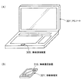
図14(A)および図14(B)に、2以上のストリームの送信および受信が可能な無線端末、すなわちMIMO送信および受信が可能な無線端末が存在する場合の無線通信システムの一例を示す。 FIGS. 14A and 14B illustrate an example of a wireless communication system when there are wireless terminals capable of transmitting and receiving two or more streams, that is, wireless terminals capable of MIMO transmission and reception.
図14(A)では、無線端末1が3つのアンテナ、無線端末2が1つのアンテナを備えている。無線端末1は3ストリームをアクセスポイント11からMIMOで受信し、無線端末2は1ストリームをアクセスポイント11から受信する。図14(B)では、無線端末1と無線端末2がそれぞれ2つのアンテナを備え、それぞれ2ストリームをアクセスポイント11からMIMOで受信する。
In FIG. 14A, the
図14(A)および図14(B)のいずれの場合も、アクセスポイント11からのダウンリンクマルチユーザMIMOにおける総ストリーム数は4である。図1では、ダウンリンクにおけるユーザ多重数が4であるのに対して、図14(A)および図14(B)の例ではユーザ多重数は2となる。
14A and 14B, the total number of streams in the downlink multiuser MIMO from the
なお、MIMO対応可能な無線端末に搭載の無線通信装置のブロック構成は、図7に示したものと同様となる。その構成および動作はこれまでのアクセスポイントのMIMO動作の説明から自明であるため、説明を省略する。 Note that the block configuration of a wireless communication device mounted on a MIMO-capable wireless terminal is the same as that shown in FIG. Since the configuration and operation are obvious from the description of the MIMO operation of the access point so far, the description is omitted.
(1ストリームでのBAフレームの送信)
図14(A)の無線端末1および図14(B)の無線端末1、2は、アクセスポイント11から複数のストリームでデータフレームを受信後、それぞれ1ストリームでBAフレームをマルチユーザMIMO送信することができる。この場合、ダウンリンクマルチユーザMIMOのストリーム数は4であるのに対し、アップリンクマルチユーザMIMOのストリーム数は2となる。つまり、アップリンクにおけるストリーム数は、ダウンリンクにおけるユーザ多重数と等しくなる。各無線端末1ストリームでBAフレームをアップリンクマルチユーザMIMO送信することは、例えば、IEEE802.11規格で規定することができる。(Transmission of BA frame in one stream)
The
アクセスポイント11は、無線端末1および2に対して空間分離情報を通知するために、共通情報フィールドにユーザ多重数およびそれに応じた直交行列を、端末情報フィールドに各無線端末が使用する直交行列の行番号(または列番号)を格納することができる。例えば、図14(A)では、ユーザ多重数は2になるため、共通情報フィールドに行列(1)を、端末情報フィールドに「無線端末1は1行目、無線端末2は2行目」などの情報を格納することができる。これら空間分離情報の通知には、第1および第2の実施形態で説明した方法(MACヘッダ、PHYヘッダ、空間分離情報付きGroup ID Managementフレーム)を用いることができる。
In order to notify the
無線端末1および2は、アクセスポイント11から通知された空間分離情報に基づいて自端末が使用するプリアンブルパターンを特定し、複数ストリームで受信したデータフレームに対するBAフレームを、それぞれ1ストリームでアップリンクマルチユーザMIMO送信する。プリアンブルパターンの特定および利用方法は、第1乃至第2の実施形態と同様のため説明を省略する。
The
また、アクセスポイント11は、空間分離情報として、ユーザポジションごとのプリアンブルパターン情報を通知することもできる。例えば、Group ID1に属する無線端末数が4、ダウンリンクマルチユーザMIMO送信の総ストリーム数が5、ユーザポジション0〜3に属する無線端末に対するダウンリンクのストリーム数がそれぞれ2、0、2、1である場合(ユーザポジション1の無線端末にはデータフレームの送信がない)、データフレームを受信したユーザポジション0、2、3に属する無線端末は、それぞれ1ストリームでBAフレームをアップリンクマルチユーザMIMO送信する。
Further, the
この場合、アクセスポイント11は、空間分離情報として、ユーザ多重数3およびそれに応じた3x3の直交行列を共通情報フィールドで通知し、各無線端末が使用する行番号(または列番号)を端末情報フィールドで通知すればよい。各無線端末は、アクセスポイント11から指定された空間分離情報を利用して、各端末が使用するプリアンブルパターンを特定する。
In this case, the
また、ユーザポジションが小さい無線端末から直交行列の行番号を昇順に割り当てる、等のルールを規定してもよい。この場合、アクセスポイント11は、空間分離情報として、3x3の直交行列およびユーザポジション毎のダウンリンクのストリーム数を通知すればよい。各無線端末は、ユーザポジション毎のストリーム数を把握することにより、ユーザ多重数を把握し、自装置が使うプリアンブルパターンを特定できる。例えば、Group ID1に属する無線端末数が4、ダウンリンクマルチユーザMIMO送信の総ストリーム数が5、ユーザポジション0〜3に属する無線端末に対するダウンリンクのストリーム数がそれぞれ2、0、2、1である場合、ユーザポジション0に属する無線端末は3x3行列の1行目、ユーザポジション2に属する無線端末は3x3行列の2行目、ユーザポジション3に属する無線端末は3x3行列の3行目などのようにプリアンブルパターンを特定できる。なお、行列の値がIEEE802.11規格で予め定められており、無線端末1〜4が内部メモリにその値を記憶している場合、アクセスポイント11は、無線端末1〜4に対して行列の値を送信する必要はなくなる。
Further, a rule such as assigning the row numbers of the orthogonal matrix in ascending order from a wireless terminal having a small user position may be defined. In this case, the
無線端末1〜4は、アクセスポイント11から明示的あるいは暗示的に通知されたアップリンクのユーザ多重数(総ストリーム数)を参照し、対応する行列を内部メモリから読み出すことができる。なお、暗示的な通知の例として、アクセスポイント11はユーザポジション毎のダウンリンクのストリーム数を通知する。各無線端末はストリーム数が0以外の無線端末数をカウントすることで、アップリンクにおけるユーザ多重数(総ストリーム数)を取得できる。
The
(複数ストリームでのBAフレームの送信)
図14(A)および(B)の無線端末1、2は、アクセスポイント11から受信したストリームと同数のストリームでBAフレームを送信することができる。例えば、図14(A)の場合、無線端末1は3ストリームでBAフレームを送信し、無線端末2は1ストリームでBAフレームを送信する。(Transmission of BA frames in multiple streams)
The
アクセスポイント11は、無線端末1および2に対して、共通情報フィールドでアップリンクにおけるストリームの総数およびそれに応じた直交行列を、端末情報フィールドで各無線端末が使用する直交行列の行番号(または列番号)を通知することができる。図14(B)では、アップリンクマルチユーザMIMOにおけるストリームの総数は4になるため、共通情報フィールドに行列(2)を、端末情報フィールドに「無線端末1は1、2行目、無線端末2は3、4行目」などの情報を格納することができる。これら空間分離情報の通知には、第1および第2の実施形態で説明した方法(MACヘッダ、PHYヘッダ、空間分離情報付きGroup ID Managementフレーム)を用いることができる。
The
無線端末1および2は、アクセスポイント11から通知された空間分離情報に基づいて自端末が使用するプリアンブルパターンを特定し、それぞれ受信したデータフレームと同数のストリームでBAフレームをアップリンクマルチユーザMIMO送信することができる。
The
また、アクセスポイント11が、空間分離情報として各無線端末がアップリンクマルチユーザMIMO送信する際に使用するストリーム数を通知するようにしてもよい。例えば、図14(B)において、「無線端末1は1ストリーム、無線端末2は2ストリーム」のような情報を通知する。ストリーム数の通知には、共通情報フィールド、端末情報フィールド、あるいはその他フィールドを利用することができる。無線端末1および2は、通知されたストリーム数に応じてBAフレームを送信する際のストリーム数を決定する。その際、「無線端末1は1ストリーム、無線端末2は1ストリーム」のように1ストリームでの送信を通知することも可能である。
Further, the
なお、アクセスポイント11が指定するストリームの総数は、アクセスポイント11の受信能力(アンテナ数)を超えない範囲で調整可能である。また、各無線端末に指定するストリーム数も各無線端末の受信能力(アンテナ数)を超えない範囲で調整可能である。
Note that the total number of streams designated by the
この他にも、アクセスポイント11から受信したストリーム数と同数のストリームでBAフレームを送信する等のルールを規定することもできる。例えば、Group ID1に属する無線端末数が4、ダウンリンクマルチユーザMIMO送信の総ストリーム数が5、ユーザポジション0〜3に属する無線端末に対するダウンリンクのストリーム数がそれぞれ2、0、2、1である場合(ユーザポジション1の無線端末にはデータフレームの送信がない)、ユーザポジション0、2、3に属する無線端末は、それぞれ2ストリーム、2ストリーム、1ストリームでBAフレームをアップリンクマルチユーザMIMO送信する。この場合もユーザポジションが小さい無線端末から直交行列の行番号を昇順に割り当てる等のルールを規定し、各無線端末がこのルールに基づいてプリアンブルパターンを特定するようにしてもよい。
In addition to this, it is also possible to define rules such as transmitting BA frames using the same number of streams as received from the
なお、行列の値がIEEE802.11規格で予め定められており、無線端末1〜4が内部メモリにその値を記憶している場合、アクセスポイント11は、無線端末1〜4に対して行列の値を送信する必要はなくなる。無線端末1〜4は、アクセスポイント11から直接的あるいは間接的に通知された総ストリーム数を参照し、対応する行列を内部メモリから読み出すことができる。
In addition, when the value of the matrix is predetermined in the IEEE 802.11 standard and the
(ストリーム数の通知方法)
MIMO送信を行うことが可能な無線端末が存在する場合、アクセスポイント11の制御部101は、共通情報フィールドを用いて、BAフレームを送信する際の総ストリーム数を(明示的または暗示的に)指定するのに加えて、端末情報フィールドを用いて、各無線端末に対してそれぞれ送信許可するストリーム数を指定することができる。また、無線端末に送信許可するストリーム数だけ、直交行列の行番号(または列番号)を端末情報フィールドで指定することも可能である。なお、アクセスポイント11の制御部101は、各無線端末が対応可能なストリーム数を、例えばアソシエーション時に各無線端末から取得してもよい。(Stream number notification method)
When there is a wireless terminal capable of performing MIMO transmission, the
アクセスポイント11の制御部101は、総ストリーム数の指定を、共通情報フィールドで行ってもよい。または、端末情報フィールドに他の無線端末の情報が含まれている場合、各無線端末向けの行番号(または列番号)の総数を計算することで総ストリーム数を把握できることから、総ストリーム数の明示的な通知を省略してもよい。
The
以下、ストリーム数を暗示的に通知する例を示す。例えば、図14(A)に示したように、無線端末1が3ストリーム、無線端末2が1ストリームの、総ストリーム数4のアップリンクマルチユーザMIMO送信の場合を考える。
Hereinafter, an example in which the number of streams is implicitly notified will be shown. For example, as shown in FIG. 14A, consider the case of uplink multiuser MIMO transmission with a total number of 4 streams in which the
アクセスポイント11の制御部101は、無線端末1に対応する端末情報フィールドに、直交行列の行番号1、2、3を設定する。これにより、無線端末1は自装置が3ストリームの送信を許可されていることを把握する。また、無線端末1は、総ストリーム数4に対応する直交行列の行番号1、2、3の各行[1, −1, 1, 1]、[1, 1, −1, 1]、[1, 1, 1, −1]に基づくプリアンブルパターンを各ストリームで用いることを把握する。上述したように、アクセスポイント11の制御部101は、総ストリーム数を共通情報フィールドで明示的に通知してもよいし、通知を省略してもよい。
The
ここで、送信許可するストリーム数を各端末情報フィールドにて明示的に通知する場合には、直交行列の行番号(または列番号)の通知を省略する構成も可能である。例えば、端末情報フィールド1に対応する無線端末のストリーム数が3であり、端末情報フィールド2に対応する無線端末のストリーム数が1であるとする。この場合には、端末情報フィールド1に対応する無線端末は、直交行列の1行目から3行目、端末情報フィールド2に対応する無線端末は4行目を用いるようにする。各無線端末は、自装置よりフィールド番号が小さい端末情報フィールドに格納されているストリーム数を合計し、合計値に1を加算することで、当該自装置が使用する行番号(または列番号)の開始値を算出できる。つまり、端末情報フィールドの小さい無線端末から順番に、直交行列の行また列を番号の昇順に割り当てる仕組みを採用することで、各無線端末に使用する行番号(または列番号)の通知を省略できる。
Here, in the case where the number of streams permitted to be transmitted is explicitly notified in each terminal information field, it is possible to omit the notification of the row number (or column number) of the orthogonal matrix. For example, it is assumed that the number of wireless terminal streams corresponding to the
ここで、各無線端末に許可するストリーム数が共通の値に限られる場合には、共通情報フィールドにて共通のストリーム数を指定するようにし、各端末情報フィールドでの個別のストリーム数の通知は行わなくてもよい。この場合も、アップリンクマルチユーザMIMOの総ストリーム数は、共通情報フィールドで明示的に通知してもよい。あるいは、共通情報フィールドでの明示的な通知を行わず、共通のストリーム数と、各端末情報フィールドの個数とから、各無線端末が総ストリーム数を把握するようにしてもよい。 Here, when the number of streams permitted to each wireless terminal is limited to a common value, the common number of streams is specified in the common information field, and the notification of the number of individual streams in each terminal information field is It does not have to be done. Also in this case, the total number of uplink multiuser MIMO streams may be explicitly notified in the common information field. Alternatively, the wireless terminal may grasp the total number of streams from the number of common streams and the number of each terminal information field without performing explicit notification in the common information field.
以上、本実施形態によれば、各無線端末に許可するストリーム数を直接または間接に指定することにより、各無線端末がそれぞれMIMO送信も併用可能となる。もし仮に、各無線端末に許可するストリーム数の指定を行わないとすると、アップリンクマルチユーザMIMOで送信される総送信ストリームの合計が、アクセスポイントで分離できる能力以上のストリーム数で送られることになり得る。また、各無線端末が、他の無線端末と重複しないプリアンブルパターンを選択できなくなる可能性もある。本実施形態では、各無線端末に許可するストリーム数を指定することより、これらの問題を解消することが可能となる。 As described above, according to the present embodiment, by directly or indirectly designating the number of streams permitted to each wireless terminal, each wireless terminal can also use MIMO transmission. If the number of streams allowed to each wireless terminal is not specified, the total number of transmission streams transmitted by uplink multiuser MIMO is transmitted with the number of streams exceeding the capability that can be separated by the access point. Can be. Also, each wireless terminal may not be able to select a preamble pattern that does not overlap with other wireless terminals. In the present embodiment, these problems can be solved by designating the number of streams permitted to each wireless terminal.
(第4の実施形態)
第1乃至第3の実施形態では、各無線端末から互いに直交するプリアンブルパターンを送信することで、アクセスポイントでアップリンクの伝搬路応答行列を推定できるようにした。本実施形態では、各無線端末が直交する周波数キャリアを用いてプリアンブルパターンを送信することで、アップリンクの伝搬路応答行列を推定できるようにする。ここでは、マルチキャリア変調方式、特にOFDM(Orthogonal Frequency Division Multiplexing)を用いる場合を想定する。なお、前述した第1乃至第3の実施形態では、マルチキャリア変調方式およびシングルキャリア変調方式のいずれも対応可能である。(Fourth embodiment)
In the first to third embodiments, an uplink propagation path response matrix can be estimated at an access point by transmitting preamble patterns orthogonal to each other from each wireless terminal. In the present embodiment, each radio terminal transmits a preamble pattern using orthogonal frequency carriers so that an uplink channel response matrix can be estimated. Here, it is assumed that a multi-carrier modulation scheme, particularly OFDM (Orthogonal Frequency Division Multiplexing) is used. In the first to third embodiments described above, both the multicarrier modulation method and the single carrier modulation method can be supported.
図15に、本実施形態に係るBAフレームの概略構成例を示す。無線端末1〜4が送信するBAフレームの概要構成例が示される。第1の実施形態と同様、BAフレームにはプリアンブルフィールド501が含まれるが、プリアンブルパターンとして設定される値が第1の実施形態と異なっている。
FIG. 15 shows a schematic configuration example of the BA frame according to the present embodiment. A schematic configuration example of the BA frame transmitted from the
各BAフレームのプリアンブルフィールド501は複数の区間からなり、各区間にはキャリアパターンP1、P2、P3、P4がそれぞれ異なる順番で割り当てられている。1つの区間は1つのOFDMシンボル区間に対応する。 The preamble field 501 of each BA frame includes a plurality of sections, and carrier patterns P1, P2, P3, and P4 are assigned to the sections in different orders. One section corresponds to one OFDM symbol section.
キャリアパターンP1は、OFDM変調のサブキャリアf1、f5、f9を用いてプリアンブルパターンを送信することを表す。キャリアパターンP2は、OFDM変調のサブキャリアf2、f6、f10を用いてプリアンブルパターンを送信することを表す。キャリアパターンP3は、OFDM変調のサブキャリアf3、f7、f11を用いてプリアンブルパターンを送信することを表す。キャリアパターンP4は、OFDM変調のサブキャリアf4、f8、f12を用いてプリアンブルパターンを送信することを表す。 The carrier pattern P1 represents that a preamble pattern is transmitted using subcarriers f1, f5, and f9 of OFDM modulation. The carrier pattern P2 represents that a preamble pattern is transmitted using subcarriers f2, f6, and f10 of OFDM modulation. The carrier pattern P3 represents that a preamble pattern is transmitted using subcarriers f3, f7, and f11 of OFDM modulation. The carrier pattern P4 represents that a preamble pattern is transmitted using subcarriers f4, f8, and f12 of OFDM modulation.
各サブキャリアで送信するプリアンブルパターンは、アクセスポイント11で既知である限り任意でよい。すべてのサブキャリアで同一のデータでもよいし、サブキャリアごとに異なるデータでも構わない。
The preamble pattern transmitted by each subcarrier may be arbitrary as long as it is known by the
各区間には、それぞれ左から順にタイミングt1、t2、t3、t4が設定されている。タイミングt1、t2、t3、t4は、プリアンブルフィールド501の該当する区間での送信タイミングを表している。各無線端末で、同じタイミングの区間では、キャリアパターンは、互いに異なっている。つまり、タイミングt1、t2、t3、t4の各々で、各無線端末がプリアンブルパターンの送信に使用するサブキャリアは、それぞれ周波数的に直交している。つまり、各無線端末のサブキャリアは互いに干渉しない。OFDMの場合、サブキャリアの周波数はお互いのサブキャリアが直交するように選ばれることから、同じサブキャリアを使用しない限り、各無線端末のサブキャリアは互いに干渉しない。 In each section, timings t1, t2, t3, and t4 are set in order from the left. Timings t1, t2, t3, and t4 represent transmission timings in the corresponding section of the preamble field 501. In each wireless terminal, carrier patterns are different from each other in the same timing section. That is, at each of timings t1, t2, t3, and t4, the subcarriers that each wireless terminal uses for transmitting the preamble pattern are orthogonal in frequency. That is, the subcarriers of the wireless terminals do not interfere with each other. In the case of OFDM, since the subcarrier frequencies are selected so that the subcarriers are orthogonal to each other, the subcarriers of each wireless terminal do not interfere with each other unless the same subcarrier is used.
例えば、タイミングt1では、無線端末1のサブキャリアはf1、f5、f9、無線端末2のサブキャリアはf2、f6、f10、無線端末3のサブキャリアはf3、f7、f11、無線端末4のサブキャリアはf4、f8、f12である。無線端末間でサブキャリアは重複しないから、無線端末間でサブキャリアが直交する。他のタイミングt2〜t4についても同様に、無線端末間でサブキャリアが直交する。無線端末1〜4には、それぞれP1〜P4の全てが異なる順序で割り当てられるから、無線端末1〜4のいずれも、f1〜f12のすべてのサブキャリアで互いに干渉することはない。このように無線端末間で同じ区間(タイミング)では異なるサブキャリアを用いるようにしつつ、区間に応じて使用するサブキャリアを切り換えることをトーンインターリーブと呼ぶ場合もある。
For example, at timing t1, the subcarrier of the
具体的な動作例として、タイミングt1では、無線端末1の制御部201は、サブキャリアf1、f5、f9にはプリアンブルパターンを割り当て、他のサブキャリアには例えばヌルデータを割り当てることでOFDMシンボルを生成し、送信する。同様に、無線端末2の制御部201は、サブキャリアf2、f6、f10にはプリアンブルパターンを割り当て、他のサブキャリアには例えばヌルデータを割り当てることでOFDMシンボルを生成し、送信する。無線端末3の制御部201は、サブキャリアf3、f7、f11にはプリアンブルパターンを割り当て、他のサブキャリアには例えばヌルデータを割り当てることでOFDMシンボルを生成し、送信する。無線端末4の制御部201は、サブキャリアf4、f8、f12にはプリアンブルパターンを割り当て、他のサブキャリアには例えばヌルデータを割り当てることでOFDMシンボルを生成し、送信する。
As a specific operation example, at timing t1, the
アクセスポイント11では、各無線端末1〜4からのOFDMシンボルを、各アンテナで同時に受信する。アクセスポイント11の受信部103または制御部101は、アンテナ毎に受信信号を復調することで、サブキャリア毎の信号を取得できる。具体的に、タイミングt1に関して、無線端末1についてはサブキャリアf1、f5、f9、無線端末2についてはサブキャリアf2、f6、f10、無線端末3についてはサブキャリアf3、f7、f11、無線端末4についてはサブキャリアf4、f8、f12についての信号を取得できる。他のタイミングt2〜t4についても同様にして、各無線端末で、順次異なるキャリアパターンに基づき、OFDMシンボルを生成し、送信する。これにより、アクセスポイント11の制御部101は、無線端末1〜4について、全ての周波数サブキャリアf1〜f12の信号をそれぞれ取得でき、よってアップリンクの伝搬路応答行列を推定することが可能となる。
In the
このように、各無線端末間で互いに直交するサブキャリアを用いてプリアンブルパターンを送信するためには、使用するキャリアパターンの順序や、キャリア毎に使用するプリアンブルパターンの情報を、各無線端末に通知する必要がある。 As described above, in order to transmit a preamble pattern using subcarriers orthogonal to each other between each wireless terminal, the information on the order of the carrier pattern used and the preamble pattern used for each carrier is notified to each wireless terminal. There is a need to.
通知の方法としては、第1乃至第3の実施形態と同様に、アクセスポイント11の制御部101が、データフレーム601〜604のMACヘッダ、PHYヘッダ、空間分離情報付きGroup ID Managementフレームの共通情報フィールドまたは端末情報フィールドまたはこれらの両方を利用して、無線端末ごとのキャリアパターンの順序や、サブキャリア毎のプリアンブルパターンなどの空間分離情報を通知することができる。なお、プリアンブルパターンがすべての無線端末、およびすべてのサブキャリアで同じ固定のものである場合は、通知を省略してもよい。
As a notification method, as in the first to third embodiments, the
通知の具体例として、キャリアパターンP1〜P4のそれぞれごとに、使用するサブキャリアの番号と、当該サブキャリアに割り当てるプリアンブルパターンとの対応を表した情報を共通情報フィールドで通知してもよい。また、無線端末別の端末情報フィールドで、P1〜P4の順序に関する情報を通知してもよい。 As a specific example of the notification, for each of the carrier patterns P1 to P4, information indicating the correspondence between the number of the subcarrier to be used and the preamble pattern assigned to the subcarrier may be notified in the common information field. Moreover, you may notify the information regarding the order of P1-P4 in the terminal information field according to radio | wireless terminal.
通知の方法は、上述した実施形態と同様の考え方で、種々の形で拡張または変形が可能である。例えば、共通情報フィールドや各端末情報フィールドで明示的に通知する方法以外にも、無線端末別の端末情報フィールドの個数や、総送信ストリームの数などを利用して、暗示的に通知することも可能である。 The notification method can be expanded or modified in various ways based on the same concept as the above-described embodiment. For example, in addition to the method of explicitly notifying in the common information field and each terminal information field, implicit notification may be performed using the number of terminal information fields for each wireless terminal, the number of total transmission streams, and the like. Is possible.
なお、プリアンブルパターンを送信するサブキャリアとしてf1〜f12を用いたが、これは一例であり、より多数または少数のサブキャリアを用いてプリアンブルパターンを送信してもよい。また、データ部を送信するサブキャリアは、プリアンブルパターンを送信したサブキャリアと同じサブキャリアでもよいし、これらとは別のサブキャリアでもよい。別のサブキャリアを用いる場合は、アクセスポイント11では、プリアンブルパターンを送信したサブキャリアの伝搬路応答から、後続するデータ部(MACフレーム部)用のサブキャリアの伝搬路応答を任意の方法で予測して求めればよい。例えばデータ部用のサブキャリアのそれぞれについて、プリアンブルパターンを送信したサブキャリアのうち最も周波数的に近いものと同じ伝搬路応答を採用してもよい。
In addition, although f1-f12 were used as a subcarrier which transmits a preamble pattern, this is an example and you may transmit a preamble pattern using more or a small number of subcarriers. Further, the subcarrier for transmitting the data part may be the same subcarrier as the subcarrier for transmitting the preamble pattern, or may be a subcarrier different from these. When another subcarrier is used, the
この他にも、各無線端末が異なるタイミングでプリアンブルパターンを送信することで、アップリンクの伝搬路応答行列を推定することができる。 In addition, the uplink channel response matrix can be estimated by transmitting a preamble pattern at different timings from each wireless terminal.
図16に、異なるタイミングでプリアンブルパターンを送信する場合のBAフレームの概略構成例を示す。キャリアパターン“P−ALL”は、OFDM変調の全てのサブキャリアf1〜f12を用いてプリアンブルパターンを送信することを表す。“NULL”はプリアンブルパターンを送信しないことを表す。プリアンブルパターンは、アクセスポイント11で既知である限り任意でよい。タイミングt1では無線端末1が、t2では無線端末2が、t3では無線端末3が、t4では無線端末4がそれぞれプリアンブルパターンを送信することにより、時間的に直交したプリアンブルパターンの送信が可能になる。
FIG. 16 shows a schematic configuration example of a BA frame when preamble patterns are transmitted at different timings. The carrier pattern “P-ALL” represents that a preamble pattern is transmitted using all subcarriers f1 to f12 of OFDM modulation. “NULL” indicates that a preamble pattern is not transmitted. The preamble pattern may be arbitrary as long as it is known at the
アクセスポイント11では、タイミングt1では無線端末1、t2では無線端末2、t3では無線端末3、t4では無線端末4からのプリアンブルパターンを受信する。これにより、アクセスポイント11の制御部101は、無線端末1〜4について、全ての周波数サブキャリアf1〜f12の信号を取得でき、アップリンクの伝搬路応答行列を推定することが可能となる。
The
このように、各無線端末間で異なるタイミングを用いてプリアンブルパターンを送信するためには、各無線端末の送信タイミングや使用するプリアンブルパターンなどの空間分離情報を、各無線端末に通知する必要がある。 As described above, in order to transmit the preamble pattern using different timings between the wireless terminals, it is necessary to notify each wireless terminal of the space separation information such as the transmission timing of each wireless terminal and the preamble pattern to be used. .
通知の方法としては、第1乃至第3の実施形態と同様に、アクセスポイント11の制御部101が、データフレーム601〜604のMACヘッダ、PHYヘッダ、空間分離情報付きGroup ID Managementフレームの共通情報フィールドまたは端末情報フィールドまたはこれらの両方を利用することができる。
As a notification method, as in the first to third embodiments, the
以上、本実施形態によれば、各無線端末が直交する周波数キャリアを用いてプリアンブルパターンを送信する。また、各無線端末がタイミングをずらしてプリアンブルパターンを送信する。これにより、アクセスポイント11は、アップリンクの伝搬路応答行列を推定することができる。
As described above, according to the present embodiment, each wireless terminal transmits a preamble pattern using orthogonal frequency carriers. In addition, each wireless terminal transmits a preamble pattern at different timings. Thereby, the
(第5の実施形態)
本実施形態では、アクセスポイントが、各無線端末からアップリンクマルチユーザMIMOで送信されるBAフレームを受信するタイミングを調整する方法を示す。(Fifth embodiment)
In the present embodiment, a method for adjusting the timing at which an access point receives a BA frame transmitted from each wireless terminal using uplink multiuser MIMO will be described.
第1の実施形態の説明で述べたように、各無線端末は、データフレーム601〜604の受信から一定時間(図2のT1参照)経過後、BAフレームの送信を行う。アクセスポイントと各無線端末の距離が同一の場合は、基本的にはアクセスポイントでは各無線端末から送信されたBAフレームは同じタイミングにて受信されると考えることができる。 As described in the description of the first embodiment, each wireless terminal transmits a BA frame after a predetermined time (see T1 in FIG. 2) has elapsed since the reception of the data frames 601 to 604. When the distance between the access point and each wireless terminal is the same, it can be considered that the BA frame transmitted from each wireless terminal is basically received at the same timing at the access point.
しかしながら、アクセスポイントと各無線端末の距離が異なると、各々の伝搬時間が異なるため、アクセスポイントからの距離が遠い無線端末ほど、アクセスポイントからデータフレームを受信するタイミングが遅延する。また、各無線端末がデータフレームを受信した後、一定時間経過後に送信するBAフレームも、アクセスポイントからの距離が遠い無線端末ほど、アクセスポイントで受信するタイミングに遅延が生じる。 However, if the distance between the access point and each wireless terminal is different, each propagation time is different. Therefore, the wireless terminal that is farther from the access point has a delay in receiving data frames from the access point. In addition, a BA frame transmitted after a certain time elapses after each wireless terminal receives a data frame causes a delay in the timing at which the wireless terminal is received at the access point as the distance from the access point increases.
そのため、アクセスポイントと各無線端末間で片方向での最大の遅延時間差をΔtとすると、アクセスポイントで各無線端末からBAフレームを受信するタイミングとしては、最大2×Δtの時間差が生じる。2×Δtの時間差が、OFDM等のガードインターバル(サイクリックプレフィクスと呼ばれる場合もある)内に収まっていれば問題ない。なお、サイクリックプレフィクスは、OFDM以外のマルチキャリア変調方式、あるいは、シングルキャリア変調方式でも用いられ得るものであり、本実施形態はOFDMに限定されるものではない。 Therefore, if the maximum delay time difference in one direction between the access point and each wireless terminal is Δt, a maximum time difference of 2 × Δt is generated as the timing at which the access point receives the BA frame from each wireless terminal. There is no problem as long as the time difference of 2 × Δt is within a guard interval such as OFDM (sometimes called a cyclic prefix). Note that the cyclic prefix can be used in a multicarrier modulation scheme other than OFDM or a single carrier modulation scheme, and the present embodiment is not limited to OFDM.
しかしながら、ガードインターバルを超えた遅延時間差で各無線端末からのBAフレームを受信すると、アップリンクマルチユーザMIMO送信の特性劣化につながる。 However, if a BA frame from each wireless terminal is received with a delay time difference exceeding the guard interval, the characteristic of uplink multiuser MIMO transmission is degraded.
そこで、本実施形態では、アクセスポイントでのBAフレームの受信タイミングを調整する。具体的には、各無線端末からのBAフレームの送信タイミングを調整する。これにより、アクセスポイントおよび各無線端末間の遅延時間差に起因するアップリンクマルチユーザMIMO送信の特性劣化を防止する。 Therefore, in this embodiment, the reception timing of the BA frame at the access point is adjusted. Specifically, the transmission timing of the BA frame from each wireless terminal is adjusted. This prevents deterioration of the characteristics of uplink multiuser MIMO transmission due to the delay time difference between the access point and each wireless terminal.
本実施形態に係るアクセスポイント11の制御部101は、データフレーム601〜604の送信前に、事前に各無線端末と通信して、各無線端末との遅延時間を推定しておく。推定する方法は任意の方法で良く、既存の様々な公知技術を用いることが可能である。例えば、アクセスポイント11から測定用フレームを送信して、各無線端末が当該測定用フレームの受信時刻を格納したフレームを返信する。アクセスポイント11の制御部101は、測定用フレームを送信した時刻と、返信されたフレームに格納されている受信時刻との差から遅延時間を測定する。別の例として、アクセスポイント11から測定用フレームを送信して、各無線端末から応答フレームを受信する。測定用フレームを送信した時刻と応答フレームを受信した時刻の差分から遅延時間を測定する。ここで述べた以外の種々の方法を用いることができる。
The
本実施形態のアクセスポイント11の制御部101は、各端末情報フィールドにて、当該無線端末によるBAフレームの送信タイミングを調整するための時間調整量を指定する。各無線端末の制御部201は、アクセスポイント11から第1乃至第3の実施形態で説明した方法により端末情報フィールドを受信し、通知された時間調整量に従って、BAフレームの送信タイミングを、基準タイミングに対して、早める、あるいは遅くする。基準タイミングは、例えばデータフレームを受信してから一定時間(図2のT1参照)後のタイミングである。各無線端末は、調整後の送信タイミングで、BAフレームを送信する。
The
ここで、アクセスポイント11が設定する各無線端末の時間調整量は、各無線端末からBAフレームを受信するタイミングが、一定の時間遅延の範囲内に収まるように決定する。一定の時間遅延の範囲は、少なくともガードインターバル以内に設定する。このような時間調整量を設定するために、事前に推定した各無線端末との遅延時間を用いる。
Here, the time adjustment amount of each wireless terminal set by the
各無線端末の時間調整量は、基準となる無線端末の送信タイミングからの相対時間を用いて設定してもよい。ここで、基準となる無線端末については、所定のタイミング(例えば、データフレームを受信してから一定時間後)を送信タイミングとして設定することができる。基準となる無線端末以外の無線端末は、当該基準となる無線端末の送信タイミングから当該相対時間だけずらしたタイミングで、BAフレームを送信する。 The time adjustment amount of each wireless terminal may be set using a relative time from the transmission timing of the reference wireless terminal. Here, for a wireless terminal serving as a reference, a predetermined timing (for example, a predetermined time after receiving a data frame) can be set as a transmission timing. Wireless terminals other than the reference wireless terminal transmit the BA frame at a timing shifted by the relative time from the transmission timing of the reference wireless terminal.
ここで、基準となる無線端末は、任意の方法で指定すればよい。例えば、共通情報フィールドに基準となる無線端末の指定を含めてもよい。または、端末情報フィールド1など、事前に決めた番号の端末情報フィールドに設定されている無線端末を、基準となる無線端末としてもよい。
Here, the reference wireless terminal may be designated by an arbitrary method. For example, designation of a wireless terminal serving as a reference may be included in the common information field. Alternatively, a wireless terminal set in a terminal information field having a predetermined number such as the
以上、本実施形態によれば、アクセスポイント11は、BAフレームの送信タイミングを制御することで、アクセスポイント11と各無線端末との通信遅延時間によらず、各無線端末からBAフレームを受信するタイミングを一定範囲(ガードインターバル等)内に収めることができる。
As described above, according to the present embodiment, the
(第6の実施形態)
本実施形態は、アクセスポイントが各無線端末から受信するBAフレームの受信電力のダイナミックレンジを、一定の範囲内に収めることを特徴とする。(Sixth embodiment)
The present embodiment is characterized in that the dynamic range of the received power of the BA frame received by the access point from each wireless terminal falls within a certain range.
これまでの実施形態の説明で述べたように、アクセスポイント11は、各無線端末からBAフレームをアップリンクマルチユーザMIMOで同時に受信する。このとき、各無線端末の送信電力が同一であったとしても、アクセスポイント11と各無線端末との距離がそれぞれ異なる場合は、信号の減衰レベルの違いにより、それぞれ異なった受信電力でBAフレームを受信する可能性がある。
As described in the description of the embodiments so far, the
図17に、無線端末1、2がアクセスポイント11に対して、それぞれ近い位置および遠い位置に配置された状況を示す。この例では、アクセスポイント11に近接した無線端末1の距離減衰量が20dBであり、アクセスポイント11から遠い位置に配置された無線端末2の距離減衰量が60dBである。この場合、アクセスポイント11は、40dBの受信電力差のあるBAフレームを同時に受信することになる。
FIG. 17 shows a situation in which the
受信電力の最大値および最小値の比または差である入力ダイナミックレンジが大きくなってしまうと、小さい受信電力のフレームが、AD変換時に量子化雑音に埋もれてしまい、正しく受信できない恐れがある。大きい入力ダイナミックレンジに対応するためには、量子化ビット数が大きいAD変換器を採用すればよいが、量子化ビット数にも限度があり、またコスト高になってしまう。 If the input dynamic range, which is the ratio or difference between the maximum value and the minimum value of received power, becomes large, a frame with a small received power may be buried in quantization noise during AD conversion and may not be received correctly. In order to cope with a large input dynamic range, an AD converter having a large number of quantization bits may be employed. However, the number of quantization bits is limited and the cost is increased.
そこで、本実施形態では、各無線端末から受信するBAフレームの受信電力のダイナミックレンジを、一定の範囲内に収めるように制御することで、上記問題を解決する。 Therefore, in this embodiment, the above problem is solved by controlling the dynamic range of the received power of the BA frame received from each wireless terminal to be within a certain range.
まず、アクセスポイント11の制御部101は、データフレームの送信前に、事前に各無線端末と通信して、各無線端末との距離減衰量を推定する。推定する方法は任意の方法で良く、既存の様々な公知技術を用いることが可能である。例えば、アクセスポイント11の制御部101は各無線端末に特定の送信電力でフレームを送信するよう指示し、当該フレームの受信電力値と、当該特定の送信電力値から距離減衰量(アップリンクの距離減衰量)を推定する。あるいは、アクセスポイント11が一定の送信電力で測定用フレームを送信し、各無線端末から当該測定フレームの受信電力値を格納したフレームを返信する。アクセスポイント11の制御部101は、測定用フレームの送信電力値と、返信されたフレームに格納された受信電力値に基づき距離減衰量(ダウンリンクの距離減衰量)を推定する。本実施形態の目的からアップリンクの距離減衰量を求めることが望ましいが、ダウンリンクとアップリンクの距離減衰量に大きな差異がないと見なせる環境では、どちらの距離減衰量を求めてもかまわない。
First, before transmitting a data frame, the
アクセスポイント11の制御部101は、各無線端末との距離減衰量に基づき、伝搬路推定対象となる無線端末により送信されるBAフレームの受信ダイナミックレンジが、一定の範囲内になるように、各無線端末の送信電力を決定する。一定の範囲内のダイナミックレンジは、少なくともアクセスポイント11に実装されているAD変換器の量子化ビット数で対応可能なダイナミックレンジ以内とする。
Based on the distance attenuation with each wireless terminal, the
アクセスポイント11の制御部101は、これまでの実施形態で説明した端末情報フィールドにて、伝搬路推定対象となる無線端末の指定を行うとともに、当該無線端末に対して決定した送信電力に関する情報(送信電力情報)を設定する。送信電力情報は、各無線端末が送信すべき送信電力値そのもので表してもよいし、通常の送信で使用する送信電力(通常送信電力)に対する相対値で表してもよい。
The
上述した説明では、各無線端末の送信電力はアクセスポイント11が決定したが、各無線端末において送信電力を決定する構成も可能である。以下、この一例を示す。
In the above description, the transmission power of each wireless terminal is determined by the
第1の例として、アクセスポイント11の制御部101は、各無線端末について推定した距離減衰量を、データフレームの各端末情報フィールドで各無線端末に通知する。各無線端末の制御部201は、各端末情報フィールドで通知された距離減衰量に応じて、BAフレームの送信電力を決定する。例えば、アクセスポイント11でのBAフレームの受信電力が、特定の値または特定の範囲内となるように、送信電力を決定する。この場合、データフレーム601〜604の共通情報フィールドにて、アクセスポイント11で期待する受信電力の値または範囲を通知してもよい。アクセスポイント11で期待する受信電力の値または範囲が予め決まっている場合には、通知を省略してもよい。
As a first example, the
第2の例として、アクセスポイント11の制御部101は、データフレームの共通情報フィールドに、当該フレームの送信電力値と、アクセスポイント11が期待する各無線端末からのBAフレームの受信電力値(期待受信電力値)を設定する。アクセスポイント11の制御部101は、このように設定したデータフレームを、共通情報フィールドに設定した送信電力値で送信する。なお、データフレームの送信電力値や、BAフレームの期待受信電力値が、予め決められた固定値である場合には、アクセスポイント11の制御部101は、これらの値の通知を省略してもよい。
As a second example, the
アクセスポイント11からデータフレームを受信した各無線端末の制御部201は、データフレームの受信電力を測定する。各無線端末の制御部201は、測定した受信電力値と、共通情報フィールドで通知された送信電力値とに基づき、アクセスポイント11から各無線端末への距離減衰量を把握する。
The
各無線端末の制御部201は、それぞれ把握した距離減衰量を基に、アクセスポイント11でのBAフレームの受信電力値が、データフレームで通知された期待受信電力値になるよう、BAフレームの送信電力を決定する。各無線端末の制御部201は、それぞれ決定した送信電力により、BAフレームを送信するよう制御する。なお、アクセスポイント11から無線端末へのダウンリンクの距離減衰量と、無線端末からアクセスポイント11へのアップリンクの距離減衰量は通信環境によっては厳密には一致するとは限らないが、概ね一致するとみなせる環境では、このような方法も可能である。あるいは、任意の方法で係数を乗じることでダウンリンクの距離減衰量を調整することにより、アップリンクの距離減衰量を推定することも可能である。
The
本実施形態では、アクセスポイント11がデータフレームを用いて受信電力値を調整する方法について説明したが、第2の実施形態における空間分離情報付きGroup ID Managementフレームや他のフレームを用いることもできる。
In the present embodiment, the method in which the
以上、本実施形態によれば、アクセスポイントが各無線端末から送信されるBAフレームの送信電力を制御することにより、アクセスポイントで受信電力値が一定のダイナミックレンジ内に収まるように、各無線端末から送信されるBAフレームを受信できる。 As described above, according to the present embodiment, each wireless terminal can control the transmission power of the BA frame transmitted from each wireless terminal by the access point so that the received power value falls within a certain dynamic range at the access point. BA frames transmitted from can be received.
(第7の実施形態)
本実施形態では、アクセスポイントおよび無線端末間でOFDM伝送を行う場合を考える。OFDM伝送においては、サブキャリア間干渉を防止するため、サブキャリア間の直交性を保つ必要がある。サブキャリア間の直交性を保つには、送信側装置と受信側装置の間で、周波数同期を必要とする。しかしながら、送信装置および受信装置間で、発振周波数のズレやドップラー偏移により、サブキャリア群の周波数オフセットが生じることがある。このことは、OFDM伝送の特性を悪くする要因となる。(Seventh embodiment)
In this embodiment, a case where OFDM transmission is performed between an access point and a wireless terminal is considered. In OFDM transmission, it is necessary to maintain orthogonality between subcarriers in order to prevent intersubcarrier interference. In order to maintain the orthogonality between the subcarriers, frequency synchronization is required between the transmission side device and the reception side device. However, a frequency offset of the subcarrier group may occur between the transmission device and the reception device due to deviation of the oscillation frequency or Doppler shift. This is a factor that deteriorates the characteristics of OFDM transmission.
特に、アップリンクマルチユーザMIMO送信の場合には、アクセスポイントは複数の無線端末から同時にフレームを受信する。このため、アクセスポイントは、無線端末ごとに異なった周波数オフセットが生じたフレームを同時に受信する場合もあり得る。この場合、周波数オフセットは、通常の送信(単一ストリームの送信)に比べ、より特性劣化の要因に繋がってしまう。 In particular, in the case of uplink multiuser MIMO transmission, the access point receives frames from multiple wireless terminals simultaneously. For this reason, the access point may receive simultaneously a frame in which a different frequency offset occurs for each wireless terminal. In this case, the frequency offset leads to a characteristic deterioration factor as compared with normal transmission (transmission of a single stream).
そこで、本実施形態は、アクセスポイントが各無線端末のサブキャリアの周波数オフセットを各々の使用周波数(基準周波数)に対し一定範囲内に収まるように制御することで、アップリンクマルチユーザMIMO送信する際の特性劣化を低減しようとするものである。 Therefore, in the present embodiment, when the access point performs uplink multiuser MIMO transmission by controlling the frequency offset of the subcarrier of each wireless terminal to be within a certain range with respect to each use frequency (reference frequency). It is intended to reduce the deterioration of the characteristics.
まず、アクセスポイント11の制御部101は、データフレーム601〜604を送信する前に、各無線端末と通信して、それぞれのサブキャリアの周波数オフセットの量を推定する。推定する方法は任意の方法で良く、既存の様々な公知技術を用いることが可能である。例えば、アクセスポイント11が、使用周波数のサブキャリア群を各無線端末に送信し、各無線端末から各サブキャリアの受信周波数を格納したフレームを返信する。アクセスポイント11の制御部101は、送信した周波数と、返信されたフレームに記載の受信周波数を比較することで、各サブキャリアの周波数オフセットの量を推定する。あるいは、アクセスポイント11が、使用周波数のサブキャリア群を各無線端末に送信するよう指示し、アクセスポイント11の制御部101は、各無線端末から受信されたサブキャリア群の周波数と、当該使用周波数との比較により、各サブキャリアの周波数オフセットの量を推定する。各サブキャリアの周波数オフセットが同一または一定範囲内とみなせる場合は、サブキャリア毎の周波数オフセットを算出せずに、OFDM信号の中心周波数(チャネル帯域の中心周波数)のオフセット量を推定してもよい。
First, before transmitting the data frames 601 to 604, the
アクセスポイント11の制御部101は、各無線端末について推定した各サブキャリアの周波数オフセット量に基づき、無線端末の周波数補正量を決定する。周波数補正量は、アクセスポイント11が各無線端末からBAフレームを受信する際の各サブキャリアの周波数オフセットが、各々の使用周波数に対し、一致または一定の範囲内に収まるように決定する。使用周波数は事前にアクセスポイント11と無線端末で固定的に設定しておいてもよいし、アクセスポイント11が使用周波数を決定して各無線端末に通知しておく構成も可能である。
The
アクセスポイント11の制御部101は、データフレーム601〜604の端末情報フィールドにて、決定した各サブキャリアの周波数補正量に関する情報(周波数補正情報)を指定する。
The
周波数補正情報は、周波数をどれだけシフトさせるかを示す絶対的な補正量で表してもよいし、基準となる無線端末の周波数の値に対してどれだけシフトさせるかを示す相対的な補正量で表してもよい。 The frequency correction information may be expressed as an absolute correction amount indicating how much the frequency is shifted, or a relative correction amount indicating how much the frequency is shifted with respect to the frequency value of the reference wireless terminal. It may be expressed as
周波数補正情報が絶対的な補正量の場合は、無線端末の制御部201は、指定された補正量だけサブキャリア群の周波数をシフトさせるよう制御する。シフトさせたサブキャリア群に基づき変調を行うことで、BAフレームを生成する。
When the frequency correction information is an absolute correction amount, the
周波数補正情報が基準となる無線端末との相対補正量の場合は、基準となる無線端末以外の無線端末の制御部201は、当該基準となる無線端末のシフト後の周波数に対し、当該相対補正量だけ周波数をシフトさせるよう制御する。シフト後の各サブキャリアに基づき、変調を行うことで、BAフレームを生成する。ただし、基準となる無線端末については、絶対補正量を指定する。基準となる無線端末以外の無線端末は、当該基準となる無線端末の絶対補正量に基づき、基準となる無線端末のシフト後の周波数を把握できる。
When the frequency correction information is a relative correction amount with the reference wireless terminal, the
ここで、基準となる無線端末は、任意の方法で指定すればよい。例えば、共通情報フィールドに基準となる無線端末の指定を含めてもよい。または、端末情報フィールド1など、事前に決めた番号の端末情報フィールドに設定されている無線端末を、基準となる無線端末に特定してもよい。
Here, the reference wireless terminal may be designated by an arbitrary method. For example, designation of a wireless terminal serving as a reference may be included in the common information field. Alternatively, a wireless terminal set in a terminal information field having a predetermined number such as the
上述した説明ではサブキャリアごとに周波数を調整する場合を示したが、各サブキャリアのオフセットが同一または一定範囲内とみなせる場合は、全体として同じ量だけ周波数を補正してもよい。この場合は、アクセスポイント11の制御部101は、事前にサブキャリア毎の周波数オフセットを算出せずに、受信したOFDM信号の中心周波数(チャネル帯域の中心周波数)と基準となる中心周波数のずれに基づき補正量を決定すればよい。無線端末では、チャネル帯域の中心周波数をシフトさせるようにサブキャリア群全体を同じ周波数だけシフトすればよい。
In the above description, the frequency is adjusted for each subcarrier. However, when the offset of each subcarrier can be regarded as the same or within a certain range, the frequency may be corrected by the same amount as a whole. In this case, the
本実施形態では、アクセスポイント11がデータフレームを用いて周波数を調整する方法について説明したが、第2の実施形態における空間分離情報付きGroup ID Managementフレームや他のフレームを用いることもできる。
In the present embodiment, the method in which the
以上、本実施形態によれば、アクセスポイントが各無線端末から送信されるBAフレームの周波数を制御することにより、各無線端末のサブキャリアの周波数オフセットを補正することが可能になる。 As described above, according to the present embodiment, the access point controls the frequency of the BA frame transmitted from each wireless terminal, whereby the subcarrier frequency offset of each wireless terminal can be corrected.
(第8の実施形態)
上述した実施形態に関する変形例について説明する。(Eighth embodiment)
The modification regarding embodiment mentioned above is demonstrated.
本変形例では、上述した異なる実施形態にわたる構成要素を適宜組み合わせてもよい。例えば、空間分離情報の送信に、空間分離情報付きGroup ID Managementフレーム、データフレームのMACヘッダ、PHYヘッダをそれぞれ組み合わせて用いてもよい。 In this modification, the constituent elements over the different embodiments described above may be appropriately combined. For example, a group ID management frame with spatial separation information, a MAC header of a data frame, and a PHY header may be used in combination for transmission of spatial separation information.
また、空間分離情報は、アップリンクマルチユーザMIMO送信されたBAフレームを空間的に分離するために必要な情報であり、BAフレームのアップリンクマルチユーザMIMO送信方法に関する情報でもある。アクセスポイント11は、空間分離情報を共通情報フィールドおよび端末情報フィールド以外のフィールドに格納することができる。また、各無線端末は、共通情報フィールドおよび端末情報フィールド以外のフィールド(例えば、レガシー規格のフィールド)から空間分離情報を取得してもよい。
Further, the spatial separation information is information necessary for spatially separating the BA frame transmitted by the uplink multiuser MIMO, and is also information regarding the uplink multiuser MIMO transmission method of the BA frame. The
アクセスポイント11が各無線端末に使用するプリアンブルパターンを指定する場合を示したが、変形例として、各無線端末が固定のプリアンブルパターンを使用する形態も可能である。この場合、アクセスポイント11は、ダウンリンクマルチユーザMIMO送信を行うとする際は、直交するプリアンブルパターンを有する無線端末の組を常に特定するようにすればよい。また、空間多重数の変動を許容する場合は、各無線端末は空間多重数に応じた固定のプリアンブルパターンを使用するようにし、アクセスポイント11は空間多重数を特定する情報を各無線端末に通知すればよい。
Although the case where the
BAフレーム送信を行う無線端末ごとに端末情報フィールドを設けてもよい。図2の例では、端末情報フィールド数は4つ設けられる。すなわち端末情報フィールド1、端末情報フィールド2、端末情報フィールド3、端末情報フィールド4が設けられる。この場合、端末情報フィールドには、無線端末の識別情報と当該無線端末に通知する空間分離情報を格納することができる。
A terminal information field may be provided for each wireless terminal that performs BA frame transmission. In the example of FIG. 2, four terminal information fields are provided. That is, a
各無線端末が使用する行番号(または列番号)は、暗示的な方法で通知することもできる。暗示的な通知として、例えば端末情報フィールドのフィールド番号によって、行番号(または列番号)を間接的に通知する方法がある。例えば、端末情報フィールド 1で指定された無線端末(すなわち端末情報フィールド1に自装置の識別情報が設定された無線端末)は、直交行列の1行目、端末情報フィールド2で指定された無線端末は、直交行列の2行目、・・・、端末情報 フィールドnで指定された無線端末は、直交行列のn行目というようにする。
The row number (or column number) used by each wireless terminal can be notified by an implicit method. As an implicit notification, for example, there is a method of indirectly informing the row number (or column number) by the field number of the terminal information field. For example, the wireless terminal specified in the terminal information field 1 (that is, the wireless terminal whose identification information is set in the terminal information field 1) is the wireless terminal specified in the
また上述した実施形態ではプリアンブルパターン等の空間分離情報を、ダウンリンクマルチユーザMIMO送信する複数のデータフレーム601〜604に含めた。より詳細には、データフレームフレーム601〜604の各々のMACヘッダ(またはPHYヘッダ)内の共通情報フィールドまたは端末情報フィールドを介して空間分離情報を通知した。別の方法として、当該空間分離情報を、単独の専用フレーム(ここではトリガーフレームと呼ぶ)に設定し、ダウンリンクマルチユーザMIMO送信では、1つ以上のデータフレームとトリガーフレームとを集約したアグリゲーションフレームを端末毎に生成し、これらのアグリゲーションフレームをダウンリンクマルチユーザMIMO送信してもよい。つまり、共通情報フィールドおよび端末情報フィールドを図3または図4に示したMACヘッダまたはPHYヘッダから取り除き、トリガーフレームとして専用のフレームにこれらのフィールドを用意する。トリガーフレームの構成例は図23のようになる。共通情報フィールドおよび端末情報フィールドは、フレームボディフィールド内でもよいし、MACヘッダ内でもよい。また、共通情報フィールドおよび端末情報フィールドが、物理ヘッダ内に配置されることを許容してもよい。フレームコントロールフィールド(FC)のTypeフィールドは、Control、Subtypeフィールドは、新規に定義した値を設定してもよい。または、Subtypeフィールドは既存の規格の値を流用し、共通情報フィールドおよび端末情報フィールドを、既存の規格で定義されたフレームの予約領域に設定することも可能である。また図24に、データフレームとトリガーフレームをアグリゲートしたアグリゲーションフレームの構成を概略的に示す。複数のデータフレームとトリガーフレームとがデリミタ(図示せず)によって互いに連結されることでアグリゲーションフレームが構成される。なおデータフレーム数は1でもよい。トリガーフレームのRAは、受信先の端末のMACアドレスでよい。
In the above-described embodiment, spatial separation information such as a preamble pattern is included in a plurality of
アクセスポイントからダウンリンクマルチユーザMIMO送信された複数のアグリゲーションフレームは、それぞれ該当する端末で受信される。端末は、アグリゲーションフレーム内の1つ以上のデータフレームのCRC検査を行うとともに、トリガーフレームから空間分離情報を取得する。この後の処理は、これまでの実施形態と同様である。例えば、端末は、CRC検査の結果に基づき、BAフレームを生成し、物理ヘッダのプリアンブルフィールドに空間分離情報に応じたプリアンブルパターンを設定して、物理ヘッダを付加したBAフレームをアクセスポイントに、アグリゲーションフレームの受信完了から時間T1後に送信する。また、端末は、別の動作例として、BAフレームと他のフレームとを集約したアグリゲーションフレームを送信してもよい。他のフレームはデータフレームでもよいし、管理フレーム等、別のフレームでもよい。この場合に、各端末から送信されるパケット長(PPDU(Physical layer Convergence Protocol Protocol Data Unit)長等)が揃うように、アクセスポイントは、トリガーフレームの共通情報フィールドまたは端末情報フィールドで、端末が送信するパケット長に関する情報を設定してもよい。指定されたパケット長に満たない場合に、フレームの末尾にパディングデータを付加してもよい。 A plurality of aggregation frames transmitted by the downlink multiuser MIMO from the access point are respectively received by the corresponding terminals. The terminal performs a CRC check on one or more data frames in the aggregation frame, and acquires spatial separation information from the trigger frame. The subsequent processing is the same as in the previous embodiments. For example, the terminal generates a BA frame based on the CRC check result, sets a preamble pattern according to the spatial separation information in the preamble field of the physical header, and aggregates the BA frame with the physical header added to the access point. Transmit after time T1 from completion of frame reception. Further, as another operation example, the terminal may transmit an aggregation frame in which the BA frame and other frames are aggregated. The other frame may be a data frame or another frame such as a management frame. In this case, the access point transmits in the common information field or terminal information field of the trigger frame so that the packet length (such as PPDU (Physical Layer Convergence Protocol Protocol Data Unit) length) is transmitted from each terminal. You may set the information regarding the packet length to perform. When the specified packet length is not reached, padding data may be added to the end of the frame.
また、上述した実施形態では、ダウンリンクのユーザ多重送信方式として、ダウンリンクマルチユーザMIMO送信を行ったが、別の方式を用いてダウンリンク送信を行い、これに対して複数の端末からBAフレームをアップリンクマルチユーザMIMO送信してもよい。例えば、別の方式として、端末ごとに異なる周波数成分を通信リソースとして用いて、複数の端末宛ての送信を同時に行う周波数多重通信がある。より詳細に、周波数成分を、1つまたは複数のサブキャリアを含むリソースユニットとして定義し、リソースユニットを最小単位の通信リソースとして用いて、複数の端末宛ての送信または複数の端末からの受信を同時に行う直交周波数分割多元接続方式(OFDMA;Orthogonal Frequency Division Multiple Access)がある。アクセスポイントから複数の端末宛ての同時送信はダウンリンクOFDMA送信、複数の端末からアクセスポイントへの同時送信はアップリンクOFDMA送信に相当する。 In the above-described embodiment, downlink multi-user MIMO transmission is performed as a downlink user multiplex transmission scheme. However, downlink transmission is performed using another scheme, and a plurality of terminals receive BA frames. May be transmitted in uplink multi-user MIMO. For example, as another method, there is frequency multiplex communication in which transmissions addressed to a plurality of terminals are simultaneously performed using different frequency components for each terminal as communication resources. More specifically, a frequency component is defined as a resource unit including one or a plurality of subcarriers, and transmission to or reception from a plurality of terminals is simultaneously performed using the resource unit as a minimum unit communication resource. There is an Orthogonal Frequency Division Multiple Access (OFDMA) system to perform (OFDMA; Orthogonal Frequency Division Multiple Access). Simultaneous transmission from the access point to a plurality of terminals corresponds to downlink OFDMA transmission, and simultaneous transmission from the plurality of terminals to the access point corresponds to uplink OFDMA transmission.
図25に、1つのチャネル(ここではチャネルMと記述している)の連続した周波数領域内に確保したリソースユニット(RU#1、RU#2、・・・RU#K)を示す。チャネルMには、互いに直交する複数のサブキャリアが配置されており、1つまたは複数の連続するサブキャリアを含む複数のリソースユニットがチャネルM内に定義されている。リソースユニット間には、1つ以上のサブキャリア(ガードサブキャリア)が配置されてもよいが、ガードサブキャリアは必須ではない。チャネル内の各サブキャリアには、サブキャリアを識別するための番号が付与されていてもよい。1つのチャネルの帯域幅は、一例として、20MHz、40MHz、80MHz、160MHzなどであるが、これらに限定されない。20MHzの複数のチャネルをまとめて1つのチャネルとしてもよい。帯域幅に応じてチャネル内のサブキャリア数またはリソースユニット数が異なってもよい。複数の端末にそれぞれ異なるリソースユニットを割り当てて同時に用いることで、アップリンクOFDMAまたはダウンリンクOFDMAが実現される。
FIG. 25 shows resource units (
ダウンリンクマルチユーザMIMOの場合には各無線端末のデータストリームをビームフォーミングにより空間的に分離していたが、ダウンリンクOFDMAの場合には、各リソースユニットは周波数的に直交しており、異なるリソースユニットでは互いに干渉しないため、アクセスポイントは端末毎に異なるリソースユニットを利用して同時にデータフレーム(または1つ以上のデータフレームを集約したアグリゲーションフレーム)を送信すればよい。この際、これらのデータフレーム(アグリゲーションフレーム)の物理ヘッダの所定フィールド(ここではSIGフィールドと呼ぶ)には、端末ごとに復号するべきリソースユニットを指定する情報を設定し、端末は当該情報で指定されたリソースユニットを復号すればよい。当該SIGフィールドは、図5で説明したL−STF、L−LTF、LSIGと同様に、チャネル帯域幅で送信し、受信した複数の端末のすべてが共通に復号できるようにすればよい。当該SIGフィールドで使用する端末の識別子は、アソシエーション時にアクセスポイントから付与されるアソシエーションID(AID)またはその一部分(Partial AID)でもよいし、MACアドレスなど別の識別子でもよい。 In the case of downlink multi-user MIMO, the data stream of each wireless terminal is spatially separated by beamforming. However, in the case of downlink OFDMA, each resource unit is orthogonal in frequency and has different resources. Since the units do not interfere with each other, the access point may transmit data frames (or an aggregation frame in which one or more data frames are aggregated) simultaneously using different resource units for each terminal. At this time, information specifying a resource unit to be decoded for each terminal is set in a predetermined field (referred to as an SIG field here) of a physical header of these data frames (aggregation frames), and the terminal is specified by the information. What is necessary is just to decode the performed resource unit. Similar to the L-STF, L-LTF, and LSIG described with reference to FIG. 5, the SIG field may be transmitted using the channel bandwidth so that all of the plurality of received terminals can be decoded in common. The identifier of the terminal used in the SIG field may be an association ID (AID) given from the access point at the time of association or a part thereof (Partial AID), or another identifier such as a MAC address.
また、前述の変形例と同様に、ダウンリンクOFDMA送信において、1つ以上のデータフレームとトリガーフレームとを集約したアグリゲーションフレームを端末毎に生成し、これらのアグリゲーションフレームをダウンリンクOFDMA送信してもよい。トリガーフレームの構成は前述した図24と同様でよい。 Similarly to the above-described modification, in downlink OFDMA transmission, an aggregation frame in which one or more data frames and a trigger frame are aggregated is generated for each terminal, and these aggregation frames may be transmitted in downlink OFDMA. Good. The configuration of the trigger frame may be the same as that shown in FIG.
また上述した実施形態では、複数の端末からアクセスポイントへ複数のBAフレームをアップリンクマルチユーザMIMO送信したが、別のユーザ多重送信方式として、アップリンクOFDMA送信してもよい。この場合、複数の端末がそれぞれ異なるリソースユニットを使用してBAフレームを同時に送信することになる。アップリンクOFDMAを行う場合、ダウンリンクのユーザ多重送信(ダウンリンクマルチユーザMIMOまたはダウンリンクOFDMA)において、上述した共通情報フィールドまたは端末情報フィールドで、プリアンブルパターンの代わりに、アップリンクのOFDMAで使用するリソースユニットを指定する情報を端末毎に通知すればよい。 In the above-described embodiment, uplink multiuser MIMO transmission of a plurality of BA frames from a plurality of terminals to an access point is performed, but uplink OFDMA transmission may be performed as another user multiplexing transmission method. In this case, a plurality of terminals simultaneously transmit BA frames using different resource units. When performing uplink OFDMA, in the downlink user multiplex transmission (downlink multiuser MIMO or downlink OFDMA), in the above-described common information field or terminal information field, the uplink OFDMA is used instead of the preamble pattern. Information specifying the resource unit may be notified for each terminal.
その他、複数の端末からアクセスポイントへの複数のBAフレームのユーザ多重送信において、OFDMAとマルチユーザMIMOを組み合わせた通信方式(OFDMA&MU−MIMOと呼ぶ)を用いることも可能である。この場合、利用するリソースユニット毎にアップリンクマルチユーザMIMO送信が行われる。すなわち、複数の端末のうちの2つ以上が同じ1つのリソースユニットに割り当てられ、同じリソースユニットでは当該2つ以上の端末が、アップリンクマルチユーザMIMO送信を行うことになる。なお、1つのリソースユニットに1つの端末のみが割り当てられる場合もあり得る。アップリンクのOFDMA&MU−MIMOを行う場合、ダウンリンクのユーザ多重送信(ダウンリンクマルチユーザMIMOまたはダウンリンクOFDMA)で、上述した共通情報フィールドまたは端末情報フィールドで空間分離情報を端末毎に通知するとともに、アップリンクのOFDMA&MU−MIMOで使用するリソースユニットを指定する情報を端末毎に通知すればよい。この場合、異なるリソースユニット間では、同一のプリアンブルパターンが用いられることも可能である。 In addition, it is also possible to use a communication scheme (referred to as OFDMA & MU-MIMO) that combines OFDMA and multiuser MIMO in user multiplex transmission of a plurality of BA frames from a plurality of terminals to an access point. In this case, uplink multiuser MIMO transmission is performed for each resource unit to be used. That is, two or more of a plurality of terminals are allocated to the same resource unit, and the two or more terminals perform uplink multiuser MIMO transmission in the same resource unit. Note that only one terminal may be allocated to one resource unit. When performing uplink OFDMA & MU-MIMO, in downlink user multiplex transmission (downlink multiuser MIMO or downlink OFDMA), the spatial separation information is reported for each terminal in the above-described common information field or terminal information field, Information specifying a resource unit used in uplink OFDMA & MU-MIMO may be notified for each terminal. In this case, the same preamble pattern can be used between different resource units.
(第9の実施形態)
図18は、第4の実施形態に係る端末またはアクセスポイントの全体構成例を示したものである。この構成例は一例であり、本実施形態はこれに限定されるものではない。端末またはアクセスポイントは、1つまたは複数のアンテナ1〜n(nは1以上の整数)と、無線LANモジュール148と、ホストシステム149を備える。無線LANモジュール148は、第1〜第3のいずれかの実施形態に係る無線通信装置に対応する。無線LANモジュール148は、ホスト・インターフェースを備え、ホスト・インターフェースで、ホストシステム149と接続される。接続ケーブルを介してホストシステム149と接続される他、ホストシステム149と直接接続されてもよい。また、無線LANモジュール148が基板にはんだ等で実装され、基板の配線を介してホストシステム149と接続される構成も可能である。ホストシステム149は、任意の通信プロトコルに従って、無線LANモジュール148およびアンテナ1〜nを用いて、外部の装置と通信を行う。通信プロトコルは、TCP/IPと、それより上位の層のプロトコルとを含んでもよい。または、TCP/IPは無線LANモジュール148に搭載し、ホストシステム149は、それより上位層のプロトコルのみを実行してもよい。この場合、ホストシステム149の構成を簡単化できる。本端末は、例えば、移動体端末、TV、デジタルカメラ、ウェアラブルデバイス、タブレット、スマートフォン、ゲーム装置、ネットワークストレージ装置、モニタ、デジタルオーディオプレーヤ、Webカメラ、ビデオカメラ、プロジェクト、ナビゲーションシステム、外部アダプタ、内部アダプタ、セットトップボックス、ゲートウェイ、プリンタサーバ、モバイルアクセスポイント、ルータ、エンタープライズ/サービスプロバイダアクセスポイント、ポータブル装置、ハンドヘルド装置等でもよい。(Ninth embodiment)
FIG. 18 shows an example of the overall configuration of a terminal or access point according to the fourth embodiment. This configuration example is an example, and the present embodiment is not limited to this. The terminal or access point includes one or
図19は、無線LANモジュールのハードウェア構成例を示す。この構成は、無線通信装置がアクセスポイントおよび非アクセスポイントのいずれに搭載される場合にも適用可能である。つまり、図7および図8に示した無線通信装置の具体的な構成の一例として適用できる。この構成例では、アンテナは1本のみであるが、2本以上のアンテナを備えていてもよい。この場合、各アンテナに対応して、送信系統(116、122〜125)、受信系統(132〜135)、PLL142、水晶発振器143およびスイッチ145のセットが配置され、各セットがそれぞれ制御回路112に接続されてもよい。アクセスポイントがマルチユーザMIMO、OFDMA&MU−MIMOを行う場合などは、このように複数のアンテナと複数のセットが用いられる。
FIG. 19 shows a hardware configuration example of the wireless LAN module. This configuration can be applied when the wireless communication apparatus is installed in either an access point or a non-access point. That is, it can be applied as an example of a specific configuration of the wireless communication apparatus shown in FIGS. In this configuration example, there is only one antenna, but two or more antennas may be provided. In this case, a set of a transmission system (116, 122 to 125), a reception system (132 to 135), a
無線LANモジュール(無線通信装置)は、ベースバンドIC(Integrated Circuit)111と、RF(Radio Frequency)IC121と、バラン125と、スイッチ145と、アンテナ147とを備える。
The wireless LAN module (wireless communication apparatus) includes a baseband IC (Integrated Circuit) 111, an RF (Radio Frequency)
ベースバンドIC111は、制御回路であるベースバンド回路112、メモリ113、ホスト・インターフェース114、CPU115、DAC(Digital to Analog Conveter)116、およびADC(Analog to Digital Converter)117を備える。
The baseband IC 111 includes a
ベースバンドIC111とRF IC121は同じ基板上に形成されてもよい。また、ベースバンドIC111とRF IC121は1チップで構成されてもよい。DAC116およびADC117の両方またはいずれか一方が、RF IC121に配置されてもよいし、別のICに配置されてもよい。またメモリ113およびCPU115の両方またはいずれか一方が、ベースバンドICとは別のICに配置されてもよい。
The baseband IC 111 and the
メモリ113は、ホストシステムとの間で受け渡しするデータを格納する。またメモリ113は、端末(アクセスポイントの場合を含む)に通知する情報、または端末(アクセスポイントの場合を含む)から通知された情報、またはこれらの両方を格納する。また、メモリ113は、CPU115の実行に必要なプログラムを記憶し、CPU115がプログラムを実行する際の作業領域として利用されてもよい。また、メモリ113は、空間分離情報等を記憶してもよい。また無線通信装置は、空間分離情報等を記憶するための外部メモリと接続されていてもよい。メモリ113はSRAM、DRAM等の揮発性メモリでもよいし、NAND、MRAM等の不揮発メモリでもよい。
The
ホスト・インターフェース114は、ホストシステムと接続するためのインターフェースである。インターフェースは、UART、SPI、SDIO、USB、PCI Expressなど何でも良い。
The
CPU115は、プログラムを実行することによりベースバンド回路112を制御するプロセッサである。ベースバンド回路112は、主にMAC層の処理および物理層の処理を行う。ベースバンド回路112、CPU115またはこれらの両方は、通信を制御する制御部に対応する。
The
ベースバンド回路112およびCPU115の少なくとも一方は、クロックを生成するクロック生成部を含み、当該クロック生成部で生成するクロックにより、内部時間を管理してもよい。ベースバンド回路112は、物理層の処理として、物理ヘッダの付加、符号化、暗号化、変調処理など行い、例えば2種類のデジタルベースバンド信号(以下、デジタルI信号とデジタルQ信号)を生成する。MIMO送信の場合は各ストリームに応じてそれぞれ2種類のデジタルベースバンド信号を生成する。ベースバンド回路112では、MIMOに関する処理、例えば、伝搬路推定の処理、送信ウェイトおよび受信ウェイトの計算処理などを行ってもよい。
At least one of the
DAC116は、ベースバンド回路112から入力される信号をDA変換する。より詳細には、DAC116はデジタルI信号をアナログのI信号に変換し、デジタルQ信号をアナログのQ信号に変換する。なお、直交変調せずに一系統の信号のままで送信する場合もありうる。前述したように、複数のアンテナを備え、一系統または複数系統の送信信号をアンテナの数だけ振り分けて送信する場合には、アンテナの数に応じた数のDAC等を設けてもよい。
The
RF IC121は、一例としてRFアナログICあるいは高周波IC、あるいはこれらの両方である。RF IC121は、フィルタ122、ミキサ123、プリアンプ(PA)124、PLL(Phase Locked Loop:位相同期回路)142、低雑音増幅器(LNA)、バラン135、ミキサ133、およびフィルタ132を備える。これらの要素のいくつかが、ベースバンドIC111または別のIC上に配置されてもよい。フィルタ122、132は、帯域通過フィルタでも、低域通過フィルタでもよい。
The
フィルタ122は、DAC116から入力されるアナログI信号およびアナログQ信号のそれぞれから所望帯域の信号を抽出する。PLL142は、水晶発振器143から入力される発振信号を用い、発振信号を分周または逓倍またはこれらの両方を行うことで、入力信号の位相に同期した、一定周波数の信号を生成する。なお、PLL142は、VCO(Voltage Controlled Oscillator)を備え、水晶発振器143から入力される発振信号に基づき、VCOを利用してフィードバック制御を行うことで、当該一定周波数の信号を得ることが一般的である。生成した一定周波数の信号は、ミキサ123およびミキサ133に入力される。PLL142は、一定周波数の信号を生成する発信装置の一例に相当する。
The
ミキサ123は、フィルタ122を通過したアナログI信号およびアナログQ信号を、PLL142から供給される一定周波数の信号を利用して、無線周波数にアップコンバートする。プリアンプ(PA)は、ミキサ123で生成された無線周波数のアナログI信号およびアナログQ信号を、所望の出力電力まで増幅する。バラン125は、平衡信号(差動信号)を不平衡信号(シングルエンド信号)に変換するための変換器である。RF IC121では平衡信号が扱われるが、RF IC121の出力からアンテナ147までは不平衡信号が扱われるため、バラン125でこれらの信号変換を行う。
The
スイッチ145は、送信時は、送信側のバラン125に接続され、受信時は、受信側のバラン134またはRF IC121に接続される。スイッチ145の制御はベースバンドIC111またはRF IC121により行われてもよいし、スイッチ145を制御する別の回路が存在し、当該回路からスイッチ145の制御を行ってもよい。
The
プリアンプ124で増幅された無線周波数のアナログI信号およびアナログQ信号は、バラン125で平衡−不平衡変換された後、アンテナ147から空間に電波として放射される。
The radio frequency analog I signal and analog Q signal amplified by the
アンテナ147は、チップアンテナでもよいし、プリント基板上に配線により形成したアンテナでもよいし、線状の導体素子を利用して形成したアンテナでもよい。
The
RF IC121におけるLNA134は、アンテナ147からスイッチ145を介して受信した信号を、雑音を低く抑えたまま、復調可能なレベルまで増幅する。バラン135は、低雑音増幅器(LNA)134で増幅された信号を、不平衡−平衡変換する。ミキサ133は、バラン135で平衡信号に変換された受信信号を、PLL142から入力される一定周波数の信号を用いてベースバンドにダウンコンバートする。より詳細には、ミキサ133は、PLL142から入力される一定周波数の信号に基づき、互いに90°位相のずれた搬送波を生成する手段を有し、バラン135で変換された受信信号を、互いに90°位相のずれた搬送波により直交復調して、受信信号と同位相のI(In−phase)信号と、これより90°位相が遅れたQ(Quad−phase)信号とを生成する。フィルタ132は、これらI信号とQ信号から所望周波数成分の信号を抽出する。フィルタ132で抽出されたI信号およびQ信号は、ゲインが調整された後に、RF IC121から出力される。
The
ベースバンドIC111におけるADC117は、RF IC121からの入力信号をAD変換する。より詳細には、ADC117はI信号をデジタルI信号に変換し、Q信号をデジタルQ信号に変換する。なお、直交復調せずに一系統の信号だけを受信する場合もあり得る。
The
前述したように、複数のアンテナが設けられる場合には、アンテナの数に応じた数のADCを設けてもよい。ベースバンドIC111は、デジタルI信号およびデジタルQ信号に基づき、復調処理、誤り訂正符号処理、物理ヘッダの処理など、物理層の処理等を行い、フレームを得る。ベースバンドIC1は、フレームに対してMAC層の処理を行う。なお、ベースバンドIC111は、TCP/IPを実装している場合は、TCP/IPの処理を行う構成も可能である。
As described above, when a plurality of antennas are provided, the number of ADCs corresponding to the number of antennas may be provided. Based on the digital I signal and the digital Q signal, the baseband IC 111 performs physical layer processing such as demodulation processing, error correction code processing, and physical header processing to obtain a frame. The
また制御回路112は、MIMOに関する処理を行ってもよい。例えば、伝搬路推定の処理、送信ウェイト計算処理、ストリームの生成および分離処理等を行う。また、UL−OFDMA、UL−MU−MIMO、およびUL−OFDMA&MU−MIMOの少なくとも1つに関する処理を行う。
The
上述した各部の処理の詳細は、図7および図8の説明から自明であるため、重複する説明は省略する。 Details of the processing of each unit described above are self-evident from the description of FIG. 7 and FIG.
(第10の実施形態)
図20(A)および図20(B)は、それぞれ第10の実施形態に係る無線端末の斜視図である。図20(A)の無線端末はノートPC301であり、図20(B)の無線端末は移動体端末321である。ノートPC301および移動体端末321は、それぞれ無線通信装置305、315を搭載している。無線通信装置305、315として、これまで説明してきた無線端末に搭載されていた無線通信装置(図8、図19等)、またはアクセスポイント11に搭載されていた無線通信装置(図7、図18等)を用いることができる。無線通信装置を搭載する無線端末は、ノートPCや移動体端末に限定されない。例えば、スマートフォン、タブレット、TV、デジタルカメラ、ウェアラブルデバイス等にも搭載可能である。また、携帯型ではなく据置型の端末であってもよい。(Tenth embodiment)
20A and 20B are perspective views of a wireless terminal according to the tenth embodiment, respectively. The wireless terminal in FIG. 20A is a
また、無線端末またはアクセスポイント11に搭載されていた無線通信装置は、メモリーカードにも搭載可能である。当該無線通信装置をメモリーカードに搭載した例を図21に示す。メモリーカード331は、無線通信装置355と、メモリーカード本体332とを含む。メモリーカード331は、外部の装置(無線端末またはアクセスポイント11等)との無線通信のために無線通信装置335を利用する。なお、図21では、メモリーカード331内の他の要素(例えばメモリ等)の記載は省略している。
Further, the wireless communication device mounted on the wireless terminal or
(第11の実施形態)
第11の実施形態では、上述した実施形態に係る無線通信装置(図7または図8等)の構成に加えて、バス、プロセッサ部、及び外部インターフェース部を備える。プロセッサ部及び外部インターフェース部は、バスを介してバッファと接続される。プロセッサ部ではファームウエアが動作する。このように、ファームウエアを無線通信装置に含める構成とすることにより、ファームウエアの書き換えによって無線通信装置の機能の変更を容易に行うことが可能となる。(Eleventh embodiment)
The eleventh embodiment includes a bus, a processor unit, and an external interface unit in addition to the configuration of the wireless communication apparatus (such as FIG. 7 or 8) according to the above-described embodiment. The processor unit and the external interface unit are connected to the buffer via the bus. Firmware operates in the processor unit. As described above, by configuring the firmware to be included in the wireless communication device, it is possible to easily change the function of the wireless communication device by rewriting the firmware.
(第12の実施形態)
第12の実施形態では、上述した実施形態に係る無線通信装置(アクセスポイントの無線通信装置または無線端末の無線通信装置)の構成に加えて、クロック生成部を備える。クロック生成部は、クロックを生成して出力端子より無線通信装置の外部にクロックを出力する。このように、無線通信装置内部で生成されたクロックを外部に出力し、外部に出力されたクロックによってホスト側を動作させることにより、ホスト側と無線通信装置側とを同期させて動作させることが可能となる。(Twelfth embodiment)
In the twelfth embodiment, in addition to the configuration of the wireless communication apparatus (access point wireless communication apparatus or wireless terminal wireless communication apparatus) according to the above-described embodiment, a clock generation unit is provided. The clock generation unit generates a clock and outputs the clock from the output terminal to the outside of the wireless communication device. Thus, the host side and the wireless communication apparatus side can be operated in synchronization by outputting the clock generated inside the wireless communication apparatus to the outside and operating the host side with the clock output to the outside. It becomes possible.
(第13の実施形態)
第13の実施形態では、上述した実施形態に係る無線通信装置(アクセスポイントの無線通信装置または無線端末の無線通信装置)の構成に加えて、電源部、電源制御部、及び無線電力給電部を含む。電源制御部は、電源部と無線電力給電部とに接続され、無線通信装置に供給する電源を選択する制御を行う。このように、電源を無線通信装置に備える構成とすることにより、電源を制御した低消費電力化動作が可能となる。(13th Embodiment)
In the thirteenth embodiment, in addition to the configuration of the wireless communication device (access point wireless communication device or wireless terminal wireless communication device) according to the above-described embodiment, a power supply unit, a power supply control unit, and a wireless power supply unit are provided. Including. The power supply control unit is connected to the power supply unit and the wireless power supply unit, and performs control to select a power supply to be supplied to the wireless communication device. As described above, by providing the wireless communication apparatus with the power supply, it is possible to perform a low power consumption operation by controlling the power supply.
(第14の実施形態)
第14の実施形態では、上述した実施形態に係る無線通信装置の構成に加えて、SIMカードを含む。SIMカードは、無線通信装置における送信部(102または202)または受信部(103または203)または制御部(101または201)と接続される。このように、SIMカードを無線通信装置に備える構成とすることにより、容易に認証処理を行うことが可能となる。(Fourteenth embodiment)
The fourteenth embodiment includes a SIM card in addition to the configuration of the wireless communication apparatus according to the above-described embodiment. The SIM card is connected to the transmission unit (102 or 202), the reception unit (103 or 203), or the control unit (101 or 201) in the wireless communication apparatus. As described above, by adopting a configuration in which the SIM card is provided in the wireless communication device, authentication processing can be easily performed.
(第15の実施形態)
第15の実施形態では、上述した実施形態に係る無線通信装置の構成に加えて、動画像圧縮/伸長部を含む。動画像圧縮/伸長部は、バスと接続される。このように、動画像圧縮/伸長部を無線通信装置に備える構成とすることにより、圧縮した動画像の伝送と受信した圧縮動画像の伸長とを容易に行うことが可能となる。(Fifteenth embodiment)
The fifteenth embodiment includes a moving image compression / decompression unit in addition to the configuration of the wireless communication apparatus according to the above-described embodiment. The moving image compression / decompression unit is connected to the bus. As described above, by providing the wireless communication device with the moving image compression / decompression unit, it is possible to easily transmit the compressed moving image and expand the received compressed moving image.
(第16の実施形態)
第16の実施形態では、上述した実施形態に係る無線通信装置(アクセスポイントの無線通信装置または無線端末の無線通信装置)の構成に加えて、LED部を含む。LED部は、送信部(102または202)または受信部(103または203)または制御部(101または201)と接続される。このように、LED部を無線通信装置に備える構成とすることにより、無線通信装置の動作状態をユーザに容易に通知することが可能となる。(Sixteenth embodiment)
In the sixteenth embodiment, in addition to the configuration of the wireless communication device (access point wireless communication device or wireless terminal wireless communication device) according to the above-described embodiment, an LED unit is included. The LED unit is connected to the transmission unit (102 or 202), the reception unit (103 or 203), or the control unit (101 or 201). In this way, by providing the wireless communication device with the LED unit, it is possible to easily notify the user of the operating state of the wireless communication device.
(第17の実施形態)
第17の実施形態では、上述した実施形態に係る無線通信装置(アクセスポイントの無線通信装置または無線端末の無線通信装置)の構成に加えて、バイブレータ部を含む。バイブレータ部は、送信部(102または202)または受信部(103または203)または制御部(101または201)と接続される。このように、バイブレータ部を無線通信装置に備える構成とすることにより、無線通信装置の動作状態をユーザに容易に通知することが可能となる。(Seventeenth embodiment)
In the seventeenth embodiment, a vibrator unit is included in addition to the configuration of the wireless communication device (access point wireless communication device or wireless terminal wireless communication device) according to the above-described embodiment. The vibrator unit is connected to the transmission unit (102 or 202), the reception unit (103 or 203), or the control unit (101 or 201). As described above, by providing the radio communication device with the vibrator unit, it is possible to easily notify the user of the operation state of the radio communication device.
(第18の実施形態)
第18の実施形態では、上述した実施形態に係る無線通信装置(アクセスポイントの無線通信装置または端末の無線通信装置)の構成に加えて、ディスプレイを含む。ディスプレイは、図示しないバスを介して、無線通信装置の制御部(101または201)に接続されてもよい。このようにディスプレイを備える構成とし、無線通信装置の動作状態をディスプレイに表示することで、無線通信装置の動作状態をユーザに容易に通知することが可能となる。(Eighteenth embodiment)
The eighteenth embodiment includes a display in addition to the configuration of the wireless communication apparatus (access point wireless communication apparatus or terminal wireless communication apparatus) according to the above-described embodiment. The display may be connected to the control unit (101 or 201) of the wireless communication device via a bus (not shown). Thus, it is possible to easily notify the user of the operation state of the wireless communication device by providing the display and displaying the operation state of the wireless communication device on the display.
(第19の実施形態)
本実施形態では、[1]無線通信システムにおけるフレーム種別、[2]無線通信装置間の接続切断の手法、[3]無線LANシステムのアクセス方式、[4]無線LANのフレーム間隔について説明する。
[1]通信システムにおけるフレーム種別
一般的に無線通信システムにおける無線アクセスプロトコル上で扱うフレームは、大別してデータ(data)フレーム、管理(management)フレーム、制御(control)フレームの3種類に分けられる。これらの種別は、通常、フレーム間で共通に設けられるヘッダ部で示される。フレーム種別の表示方法としては、1つのフィールドで3種類を区別できるようにしてあってもよいし、2つのフィールドの組み合わせで区別できるようにしてあってもよい。(Nineteenth embodiment)
In this embodiment, [1] a frame type in a wireless communication system, [2] a method of disconnecting connections between wireless communication apparatuses, [3] an access method of a wireless LAN system, and [4] a frame interval of the wireless LAN will be described.
[1] Frame Type in Communication System In general, frames handled on a radio access protocol in a radio communication system are roughly classified into three types: a data frame, a management frame, and a control frame. These types are usually indicated by a header portion provided in common between frames. As a display method of the frame type, three types may be distinguished by one field, or may be distinguished by a combination of two fields.
管理フレームは、他の無線通信装置との間の物理的な通信リンクの管理に用いるフレームである。例えば、他の無線通信装置との間の通信設定を行うために用いられるフレームや通信リンクをリリースする(つまり接続を切断する)ためのフレーム、無線通信装置でのパワーセーブ動作に係るフレームがある。 The management frame is a frame used for managing a physical communication link with another wireless communication apparatus. For example, there are a frame used for setting communication with another wireless communication device, a frame for releasing a communication link (that is, disconnecting), and a frame related to a power saving operation in the wireless communication device. .
データフレームは、他の無線通信装置と物理的な通信リンクが確立した上で、無線通信装置の内部で生成されたデータを他の無線通信装置に送信するフレームである。データは本実施形態の上位層で生成され、例えばユーザの操作によって生成される。 The data frame is a frame for transmitting data generated inside the wireless communication device to the other wireless communication device after establishing a physical communication link with the other wireless communication device. Data is generated in an upper layer of the present embodiment, for example, generated by a user operation.
制御フレームは、データフレームを他の無線通信装置との間で送受(交換)する際の制御に用いられるフレームである。無線通信装置がデータフレームや管理フレームを受信した場合にその送達確認のために送信される応答フレームは、制御フレームに属する。 The control frame is a frame used for control when a data frame is transmitted / received (exchanged) to / from another wireless communication apparatus. When the wireless communication apparatus receives a data frame or a management frame, the response frame transmitted for confirmation of delivery belongs to the control frame.
これら3種類のフレームは、物理層で必要に応じた処理を経て物理パケットとしてアンテナを経由して送出される。なお、接続確立の手順においては、接続要求フレームと接続受付フレームが管理フレームであり、接続受付フレームへの確認フレームは制御フレームの応答フレームを用いることができる。 These three types of frames are sent out via the antenna as physical packets after undergoing processing as required in the physical layer. In the connection establishment procedure, a connection request frame and a connection acceptance frame are management frames, and a response frame of a control frame can be used as a confirmation frame for the connection acceptance frame.
[2]無線通信装置間の接続切断の手法
接続の切断には、明示的な手法と暗示的な手法とがある。明示的な手法としては、接続している無線通信装置のいずれか一方が切断のためのフレームを送信する。このフレームは管理フレームに分類される。切断のためのフレームは、例えば接続をリリースするという意味でリリースフレームと呼ぶことがある。通常、リリースフレームを送信する側の無線通信装置ではリリースフレームを送信した時点で、リリースフレームを受信する側の無線通信装置ではリリースフレームを受信した時点で、接続の切断と判定する。その後、通信フェーズでの初期状態、例えば通信相手の無線通信装置を探索する状態に戻る。これは、切断のためのフレームを送信する際には、接続先の無線通信装置と通信距離が離れて無線信号が受信不可あるいは復号不可になるといった、物理的な無線リンクが確保できないことがあるからである。[2] Methods for disconnecting connections between wireless communication devices There are explicit methods and implicit methods for disconnecting connections. As an explicit method, one of the connected wireless communication apparatuses transmits a frame for disconnection. This frame is classified as a management frame. The frame for disconnection may be called a release frame in the sense that, for example, the connection is released. Usually, the wireless communication device that transmits the release frame determines that the connection is disconnected when the release frame is transmitted and the wireless communication device that receives the release frame receives the release frame. Thereafter, the process returns to the initial state in the communication phase, for example, the state of searching for the wireless communication device of the communication partner. This is because when a frame for disconnection is transmitted, a physical radio link may not be secured such that a radio signal cannot be received or decoded due to a communication distance away from the connection destination radio communication device. Because.
一方、暗示的な手法としては、一定期間接続を確立した接続相手の無線通信装置からフレーム送信(データフレーム及び管理フレームの送信、あるいは自端末が送信したフレームへの応答フレームの送信、あるいはこれらの両方)を検知しなかった場合に、接続状態の切断の判定を行う。このような手法があるのは、上述のように接続の切断を判定するような状況では、接続先の無線通信装置と通信距離が離れて無線信号が受信不可あるいは復号不可になるなど物理的な無線リンクが確保できない状態が考えられるからである。すなわち、リリースフレームの受信を期待できないからである。 On the other hand, as an implicit method, frame transmission (data frame and management frame transmission, or response frame transmission to the frame transmitted by the terminal itself, or these If both are not detected, the connection state is determined to be disconnected. There is such a method in the situation where it is determined that the connection is disconnected as described above, such that the communication distance is away from the connection-destination wireless communication device, and the wireless signal cannot be received or decoded. This is because a wireless link cannot be secured. That is, it cannot be expected to receive a release frame.
暗示的な方法で接続の切断を判定する具体例としては、タイマを使用する。例えば、送達確認応答フレームを要求するデータフレームを送信する際、当該フレームの再送期間を制限する第1のタイマ(例えばデータフレーム用の再送タイマ)を起動し、第1のタイマが切れるまで(つまり所望の再送期間が経過するまで)当該フレームへの送達確認応答フレームを受信しないと再送を行う。当該フレームへの送達確認応答フレームを受信すると第1のタイマは止められる。 A timer is used as a specific example of determining disconnection by an implicit method. For example, when transmitting a data frame requesting a delivery confirmation response frame, a first timer (for example, a retransmission timer for a data frame) that limits a retransmission period of the frame is started, and until the first timer expires (that is, If a delivery confirmation response frame is not received (until the desired retransmission period elapses), retransmission is performed. The first timer is stopped when a delivery confirmation response frame to the frame is received.
一方、送達確認応答フレームを受信せず第1のタイマが切れると、例えば接続相手の無線通信装置がまだ(通信レンジ内に)存在するか(言い換えれば、無線リンクが確保できているか)を確認するための管理フレームを送信し、それと同時に当該フレームの再送期間を制限する第2のタイマ(例えば管理フレーム用の再送タイマ)を起動する。第1のタイマと同様、第2のタイマでも、第2のタイマが切れるまで当該フレームへの送達確認応答フレームを受信しないと再送を行い、第2のタイマが切れると接続が切断されたと判定する。 On the other hand, when the first timer expires without receiving the delivery confirmation response frame, for example, it is confirmed whether the other party's wireless communication device still exists (within the communication range) (in other words, the wireless link can be secured). And a second timer for limiting the retransmission period of the frame (for example, a retransmission timer for the management frame) is started at the same time. Similar to the first timer, the second timer also performs retransmission if it does not receive an acknowledgment frame for the frame until the second timer expires, and determines that the connection has been disconnected when the second timer expires. .
あるいは接続相手の無線通信装置からフレームを受信すると第3のタイマを起動し、新たに接続相手の無線通信装置からフレームを受信するたびに第3のタイマを止め、再び初期値から起動する。第3のタイマが切れると前述と同様に接続相手の無線通信装置がまだ(通信レンジ内に)存在するか(言い換えれば、無線リンクが確保できているか)を確認するための管理フレームを送信し、それと同時に当該フレームの再送期間を制限する第2のタイマ(例えば管理フレーム用の再送タイマ)を起動する。この場合も、第2のタイマが切れるまで当該フレームへの送達確認応答フレームを受信しないと再送を行い、第2のタイマが切れると接続が切断されたと判定する。後者の、接続相手の無線通信装置がまだ存在するかを確認するための管理フレームは、前者の場合の管理フレームとは異なるものであってもよい。また後者の場合の管理フレームの再送を制限するためのタイマはここでは第2のタイマとして前者の場合と同じものを用いたが、異なるタイマを用いるようにしてもよい。 Alternatively, when a frame is received from the connection partner wireless communication device, the third timer is started. Whenever a new frame is received from the connection partner wireless communication device, the third timer is stopped and restarted from the initial value. When the third timer expires, a management frame is transmitted to confirm whether the other party's wireless communication device still exists (within the communication range) (in other words, whether the wireless link has been secured) as described above. At the same time, a second timer (for example, a retransmission timer for management frames) that limits the retransmission period of the frame is started. Also in this case, if the acknowledgment response frame to the frame is not received until the second timer expires, retransmission is performed, and if the second timer expires, it is determined that the connection has been disconnected. The latter management frame for confirming whether the wireless communication apparatus of the connection partner still exists may be different from the management frame in the former case. In the latter case, the timer for limiting retransmission of the management frame is the same as that in the former case as the second timer, but a different timer may be used.
[3]無線LANシステムのアクセス方式
例えば複数の無線通信装置と通信または競合することを想定した無線LANシステムがある。IEEE802.11(拡張規格なども含む)無線LANではCSMA/CAをアクセス方式の基本としている。ある無線通信装置の送信を把握し、その送信終了から固定時間を置いて送信を行う方式では、その無線通信装置の送信を把握した複数の無線通信装置で同時に送信を行うことになり、その結果、無線信号が衝突してフレーム送信に失敗する。ある無線通信装置の送信を把握し、その送信終了からランダム時間待つことで、その無線通信装置の送信を把握した複数の無線通信装置での送信が確率的に分散することになる。よって、ランダム時間の中で最も早い時間を引いた無線通信装置が1つなら無線通信装置のフレーム送信は成功し、フレームの衝突を防ぐことができる。ランダム値に基づき送信権の獲得が複数の無線通信装置間で公平になることから、Carrier Avoidanceを採用した方式は、複数の無線通信装置間で無線媒体を共有するために適した方式であるということができる。[3] Access method of wireless LAN system For example, there is a wireless LAN system that is assumed to communicate or compete with a plurality of wireless communication devices. In the IEEE802.11 (including extended standards) wireless LAN, CSMA / CA is the basic access method. In the method of grasping the transmission of a certain wireless communication device and performing transmission after a fixed time from the end of the transmission, the transmission is performed simultaneously by a plurality of wireless communication devices grasping the transmission of the wireless communication device, and as a result The radio signal collides and frame transmission fails. By grasping the transmission of a certain wireless communication device and waiting for a random time from the end of the transmission, the transmissions by a plurality of wireless communication devices that grasp the transmission of the wireless communication device are stochastically dispersed. Therefore, if there is one wireless communication device that has drawn the earliest time in the random time, the frame transmission of the wireless communication device is successful, and frame collision can be prevented. Since acquisition of transmission rights is fair among a plurality of wireless communication devices based on a random value, the method employing Carrier Aviation is a method suitable for sharing a wireless medium between a plurality of wireless communication devices. be able to.
[4]無線LANのフレーム間隔
IEEE802.11無線LANのフレーム間隔について説明する。IEEE802.11無線LANで用いられるフレーム間隔は、distributed coordination function interframe space(DIFS)、arbitration interframe space(AIFS)、point coordination function interframe space(PIFS)、short interframe space(SIFS)、extended interframe space(EIFS)、reduced interframe space(RIFS)の6種類ある。[4] Wireless LAN Frame Interval The IEEE 802.11 wireless LAN frame interval will be described. The frame interval used in the IEEE 802.11 wireless LAN is as follows: distributed coordination function inter frame space (DIFS), arbitration inter frame space (AIFS), point coordination function intra interface space interface (IFS). There are six types, reduced interface space (RIFS).
フレーム間隔の定義は、IEEE802.11無線LANでは送信前にキャリアセンスアイドルを確認して開けるべき連続期間として定義されており、厳密な前のフレームからの期間は議論しない。従ってここでのIEEE802.11無線LANシステムでの説明においてはその定義を踏襲する。IEEE802.11無線LANでは、CSMA/CAに基づくランダムアクセスの際に待つ時間を固定時間とランダム時間との和としており、固定時間を明確にするためこのような定義になっているといえる。 In the IEEE802.11 wireless LAN, the frame interval is defined as a continuous period to be opened after confirming carrier sense idle before transmission, and a strict period from the previous frame is not discussed. Therefore, in the description of the IEEE802.11 wireless LAN system here, the definition follows. In the IEEE802.11 wireless LAN, the time to wait for random access based on CSMA / CA is the sum of a fixed time and a random time, and it can be said that such a definition is used to clarify the fixed time.
DIFSとAIFSとは、CSMA/CAに基づき他の無線通信装置と競合するコンテンション期間にフレーム交換開始を試みるときに用いるフレーム間隔である。DIFSは、トラヒック種別による優先権の区別がないとき、AIFSはトラヒック種別(Traffic Identifier:TID)による優先権が設けられている場合に用いる。 DIFS and AIFS are frame intervals used when attempting to start frame exchange during a contention period competing with other wireless communication devices based on CSMA / CA. The DIFS is used when priority according to the traffic type (Traffic Identifier: TID) is provided when there is no distinction of the priority according to the traffic type.
DIFSとAIFSとで係る動作としては類似しているため、以降では主にAIFSを用いて説明する。IEEE802.11無線LANでは、MAC層でフレーム交換の開始などを含むアクセス制御を行う。さらに、上位層からデータを渡される際にQoS(Quality of Service)対応する場合には、データとともにトラヒック種別が通知され、トラヒック種別に基づいてデータはアクセス時の優先度のクラス分けがされる。このアクセス時のクラスをアクセスカテゴリ(Access Category;AC)と呼ぶ。従って、アクセスカテゴリごとにAIFSの値が設けられることになる。 Since operations related to DIFS and AIFS are similar, the following description will be mainly given using AIFS. In the IEEE802.11 wireless LAN, access control including the start of frame exchange is performed in the MAC layer. Further, when QoS (Quality of Service) is supported when data is passed from an upper layer, the traffic type is notified together with the data, and the data is classified according to the priority at the time of access based on the traffic type. This class at the time of access is called an access category (AC). Therefore, an AIFS value is provided for each access category.
PIFSは、競合する他の無線通信装置よりも優先権を持つアクセスができるようにするためのフレーム間隔であり、DIFS及びAIFSのいずれの値よりも期間が短い。SIFSは、応答系の制御フレームの送信時あるいは一旦アクセス権を獲得した後にバーストでフレーム交換を継続する場合に用いることができるフレーム間隔である。EIFSはフレーム受信に失敗した場合に発動されるフレーム間隔である。 The PIFS is a frame interval for enabling access with priority over other competing wireless communication apparatuses, and has a shorter period than any value of DIFS and AIFS. SIFS is a frame interval that can be used when transmitting a control frame of a response system or when frame exchange is continued in a burst after acquiring an access right once. EIFS is a frame interval that is triggered when frame reception fails.
RIFSは一旦アクセス権を獲得した後にバーストで同一無線通信装置に複数のフレームを連続して送信する場合に用いることができるフレーム間隔であり、RIFSを用いている間は送信相手の無線通信装置からの応答フレームを要求しない。 The RIFS is a frame interval that can be used when a plurality of frames are continuously transmitted to the same wireless communication device in bursts after acquiring the access right once. Do not request a response frame.
ここでIEEE802.11無線LANにおけるランダムアクセスに基づく競合期間のフレーム交換の一例を図29に示す。 Here, FIG. 29 shows an example of a frame exchange in a contention period based on random access in the IEEE 802.11 wireless LAN.
ある無線通信装置においてデータフレーム(W_DATA1)の送信要求が発生した際に、キャリアセンスの結果、媒体がビジーである(busy medium)と認識する場合を想定する。
この場合、キャリアセンスがアイドルになった時点から固定時間のAIFSを空け、その後ランダム時間(random backoff)空いたところで、データフレームW_DATA1を通信相手に送信する。It is assumed that when a transmission request for a data frame (W_DATA1) is generated in a certain wireless communication apparatus, the medium is recognized as busy as a result of carrier sense.
In this case, a fixed time AIFS is released from the point when the carrier sense becomes idle, and then a data frame W_DATA1 is transmitted to the communication partner when a random time (random backoff) is available.
ランダム時間は0から整数で与えられるコンテンションウィンドウ(Contention Window:CW)の間の一様分布から導かれる擬似ランダム整数にスロット時間をかけたものである。ここで、CWにスロット時間をかけたものをCW時間幅と呼ぶ。CWの初期値はCWminで与えられ、再送するたびにCWの値はCWmaxになるまで増やされる。CWminとCWmaxの両方とも、AIFSと同様アクセスカテゴリごとの値を持つ。W_DATA1の送信先の無線通信装置では、データフレームの受信に成功するとその受信終了時点からSIFS後に応答フレーム(W_ACK1)を送信する。W_DATA1を送信した無線通信装置は、W_ACK1を受信すると送信バースト時間制限内であればまたSIFS後に次のフレーム(例えばW_DATA2)を送信することができる。 The random time is obtained by multiplying a pseudo-random integer derived from a uniform distribution between a contention window (Content Window: CW) given by an integer from 0 to a slot time. Here, CW multiplied by slot time is referred to as CW time width. The initial value of CW is given by CWmin, and every time retransmission is performed, the value of CW is increased until it reaches CWmax. Both CWmin and CWmax have values for each access category similar to AIFS. When the wireless communication apparatus to which W_DATA1 is transmitted successfully receives the data frame, it transmits a response frame (W_ACK1) after SIFS from the reception end time. The wireless communication apparatus that has transmitted W_DATA1 can transmit the next frame (for example, W_DATA2) after SIFS if W_ACK1 is received and within the transmission burst time limit.
AIFS、DIFS、PIFS及びEIFSは、SIFSとスロット時間との関数になるが、SIFSとスロット時間とは物理層ごとに規定されている。また、AIFS、CWmin及びCWmaxなどアクセスカテゴリごとに値が設けられるパラメータは、通信グループ(IEEE802.11無線LANではBasic Service Set(BSS))ごとに設定可能であるが、デフォルト値が定められている。 AIFS, DIFS, PIFS, and EIFS are functions of SIFS and slot time. SIFS and slot time are defined for each physical layer. Also, parameters such as AIFS, CWmin, and CWmax that can be set for each access category can be set for each communication group (Basic Service Set (BSS) in the IEEE802.11 wireless LAN), but default values are set. .
例えば、802.11acの規格策定では、SIFSは16μs、スロット時間は9μsであるとして、それによってPIFSは25μs、DIFSは34μs、AIFSにおいてアクセスカテゴリがBACKGROUND(AC_BK)のフレーム間隔はデフォルト値が79μs、BEST EFFORT(AC_BE)のフレーム間隔はデフォルト値が43μs、VIDEO(AC_VI)とVOICE(AC_VO)のフレーム間隔はデフォルト値が34μs、CWminとCWmaxとのデフォルト値は、各々AC_BKとAC_BEとでは31と1023、AC_VIでは15と31、AC_VOでは7と15になるとする。なお、EIFSは、SIFSとDIFSと最も低速な必須の物理レートで送信する場合の応答フレームの時間長の和である。本実施形態では、このようなフレーム間隔のパラメータを用いる無線通信システムを通信レンジの広い干渉システムとして想定する。 For example, in the 802.11ac standard formulation, the SIFS is 16 μs and the slot time is 9 μs. Accordingly, the PIFS is 25 μs, the DIFS is 34 μs, and the frame interval of the access category BACKGROUND (AC_BK) in AIFS is 79 μs as a default value. The frame interval of BEST EFFORT (AC_BE) has a default value of 43 μs, the frame interval of VIDEO (AC_VI) and VOICE (AC_VO) has a default value of 34 μs, and the default values of CWmin and CWmax are 31 and 1023 for AC_BK and AC_BE, respectively. , AC_VI is 15 and 31, and AC_VO is 7 and 15. Note that EIFS is the sum of the time lengths of response frames in the case of transmitting at the slowest required physical rate with SIFS and DIFS. In the present embodiment, a wireless communication system using such a frame interval parameter is assumed as an interference system having a wide communication range.
本実施形態で用いられる用語は、広く解釈されるべきである。例えば用語“プロセッサ”は、汎用目的プロセッサ、中央処理装置(CPU)、マイクロプロセッサ、デジタル信号プロセッサ(DSP)、コントローラ、マイクロコントローラ、状態マシンなどを包含してもよい。状況によって、“プロセッサ”は、特定用途向け集積回路、フィールドプログラマブルゲートアレイ(FPGA)、プログラム可能論理回路 (PLD)などを指してもよい。“プロセッサ”は、複数のマイクロプロセッサのような処理装置の組み合わせ、DSPおよびマイクロプロセッサの組み合わせ、DSPコアと協働する1つ以上のマイクロプロセッサを指してもよい。 The terms used in this embodiment should be interpreted widely. For example, the term “processor” may include general purpose processors, central processing units (CPUs), microprocessors, digital signal processors (DSPs), controllers, microcontrollers, state machines, and the like. In some situations, a “processor” may refer to an application specific integrated circuit, a field programmable gate array (FPGA), a programmable logic circuit (PLD), or the like. “Processor” may refer to a combination of processing devices such as a plurality of microprocessors, a combination of a DSP and a microprocessor, and one or more microprocessors that cooperate with a DSP core.
別の例として、用語“メモリ”は、電子情報を格納可能な任意の電子部品を包含してもよい。“メモリ”は、ランダムアクセスメモリ(RAM)、読み出し専用メモリ(ROM)、プログラム可能読み出し専用メモリ(PROM)、消去可能プログラム可能読み出し専用メモリ(EPROM)、電気的消去可能PROM(EEPROM)、不揮発性ランダムアクセスメモリ(NVRAM)、フラッシュメモリ、磁気または光学データストレージを指してもよく、これらはプロセッサによって読み出し可能である。プロセッサがメモリに対して情報を読み出しまたは書き込みまたはこれらの両方を行うならば、メモリはプロセッサと電気的に通信すると言うことができる。メモリは、プロセッサに統合されてもよく、この場合も、メモリは、プロセッサと電気的に通信していると言うことができる。 As another example, the term “memory” may encompass any electronic component capable of storing electronic information. “Memory” means random access memory (RAM), read only memory (ROM), programmable read only memory (PROM), erasable programmable read only memory (EPROM), electrically erasable PROM (EEPROM), non-volatile It may refer to random access memory (NVRAM), flash memory, magnetic or optical data storage, which can be read by the processor. If the processor reads and / or writes information to the memory, the memory can be said to be in electrical communication with the processor. The memory may be integrated into the processor, which again can be said to be in electrical communication with the processor.
以上説明した本実施形態において、複数の端末が送信するデータフレーム等のフレームは、異なる内容のフレームであっても、同一の内容のフレームでもよい。一般的な表現として、複数の端末が第Xのフレームを送信またはアクセスポイントが複数の第Xフレームを受信すると表現するとき、これらの第Xのフレームの内容は同じであっても、異なってもよい。 In the present embodiment described above, frames such as data frames transmitted by a plurality of terminals may be frames having different contents or frames having the same contents. As a general expression, when expressing that a plurality of terminals transmit an Xth frame or an access point receives a plurality of Xth frames, the contents of these Xth frames may be the same or different. Good.
また、本明細書で述べるフレームは、例えばIEEE802.11規格でフレームと呼ばれているもののみならず、パケットと呼ばれているものであってもよい。 Further, the frame described in the present specification may be not only a frame called in the IEEE 802.11 standard but also a packet called a packet.
以上説明した本実施形態における一部機能もしくは全ての機能は、ソフトウェア処理により実現可能である。 Some or all of the functions in the present embodiment described above can be realized by software processing.
なお、本発明は上記実施形態そのままに限定されるものではなく、実施段階ではその要旨を逸脱しない範囲で構成要素を変形して具体化できる。また、上記実施形態に開示されている複数の構成要素の適宜な組み合わせにより、種々の発明を形成できる。例えば、実施形態に示される全構成要素から幾つかの構成要素を削除してもよい。さらに、異なる実施形態にわたる構成要素を適宜組み合わせてもよい。 Note that the present invention is not limited to the above-described embodiment as it is, and can be embodied by modifying the constituent elements without departing from the scope of the invention in the implementation stage. In addition, various inventions can be formed by appropriately combining a plurality of components disclosed in the embodiment. For example, some components may be deleted from all the components shown in the embodiment. Furthermore, constituent elements over different embodiments may be appropriately combined.
11:アクセスポイント(無線端末)
12A、12B、12C、12D:アンテナ
1、2、3、4:無線端末(ステーション)
1A、2A、3A、4A:アンテナ
21、22、23、24:ビーム
601、602、603、604:データフレーム
611、612、613、614:BAフレーム
T1:期間
t1、t2、t3、t4:送信タイミング
501:プリアンブルフィールド
h11〜h14、h21〜h24、h31〜h34、h41〜h44:アップリンクの伝搬路応答
101、201:制御部
102、202:送信部
103、203:受信部
104、204:バッファ
105、205:無線通信部
111、211:ベースバンド部
121、221:RF部
122、222:送信回路
123、223:受信回路
112、212:制御回路
113、213:送信処理回路
114、214:受信処理回路
115、116、215、216:DA変換回路
117、118、217、218:AD変換回路
301:ノートPC
305、315、355:無線通信装置
321:移動体端末
331:メモリーカード
332:メモリーカード本体11: Access point (wireless terminal)
12A, 12B, 12C, 12D:
1A, 2A, 3A, 4A:
305, 315, 355: Wireless communication device 321: Mobile terminal 331: Memory card 332: Memory card body
Claims (20)
前記複数の第1フレームに対する送達確認応答を表す、多重送信される複数の第2フレームを受信する受信部と、
制御部とを備え、
前記複数の第2フレームの送信に必要な第1情報が前記複数の第1フレームに設定されており、
前記制御部は、前記第1情報に基づいて、前記複数の第2フレームを分離する
無線通信装置。 A transmitter that multiplex-transmits a plurality of first frames;
A receiving unit that receives a plurality of second frames that are multiplexed and represents a delivery confirmation response to the plurality of first frames;
A control unit,
First information necessary for transmission of the plurality of second frames is set in the plurality of first frames,
The control unit is a wireless communication device that separates the plurality of second frames based on the first information.
制御部とを備え、
前記第1情報として前記複数の第2フレームの送信に必要な情報が設定されており、
前記制御部は、前記第1情報に基づいて、前記複数の第2フレームを分離する
無線通信装置。 A transmission unit configured to transmit a frame in which the first information is set, and to multiplex-transmit a plurality of first frames; and to receive a plurality of second frames to be transmitted that represent a delivery confirmation response to the plurality of first frames. And
A control unit,
Information necessary for transmission of the plurality of second frames is set as the first information,
The control unit is a wireless communication device that separates the plurality of second frames based on the first information.
前記第1情報は、前記空間多重で送信された前記複数の第2フレームの分離に必要な情報である請求項1乃至請求項2のいずれか一項に記載の無線通信装置。 The plurality of second frames are transmitted by spatial multiplexing,
The radio communication apparatus according to claim 1, wherein the first information is information necessary for separating the plurality of second frames transmitted by the spatial multiplexing.
前記第1情報は、前記複数の第2フレームが送信される複数の周波数成分を指定する情報を含む請求項1乃至請求項2のいずれか一項に記載の無線通信装置。 The plurality of second frames are transmitted by frequency multiplexing,
3. The wireless communication device according to claim 1, wherein the first information includes information designating a plurality of frequency components at which the plurality of second frames are transmitted.
前記第1フレームに対する送達確認応答を表す第2フレームを送信する送信部と、
制御部とを備え、
前記第1フレームは、前記第2フレームを他の第2フレームと共に多重送信する際に必要な第1情報を含み、
前記制御部は、前記第1情報に基づいて、前記第2フレームを生成する無線通信装置。 A receiving unit that receives a first frame multiplexed with another first frame;
A transmission unit for transmitting a second frame representing a delivery confirmation response to the first frame;
A control unit,
The first frame includes first information required when multiplexing the second frame together with other second frames,
The control unit is a wireless communication device that generates the second frame based on the first information.
前記第1フレームに対する送達確認応答を表す第2フレームを送信する送信部と、
制御部とを備え、
前記第1情報は、前記第2フレームを、他の第2フレームと共に多重送信する際に必要な情報であり、
前記制御部は、前記第1情報に基づいて、前記第2フレームを生成する無線通信装置。 A receiving unit that receives a frame in which the first information is set and receives a first frame that is multiplexed with another first frame;
A transmission unit for transmitting a second frame representing a delivery confirmation response to the first frame;
A control unit ,
The first information is information necessary for multiplexing and transmitting the second frame together with other second frames,
The control unit is a wireless communication device that generates the second frame based on the first information.
前記第1情報は、前記空間多重で送信される前記第2フレームおよび前記他の第2フレームの分離に必要な情報である請求項11乃至12に記載の無線通信装置。 The second frame is transmitted by spatial multiplexing with the other second frame,
The wireless communication device according to claim 11, wherein the first information is information necessary for separating the second frame and the other second frame transmitted by the spatial multiplexing.
前記第1情報は、前記第2フレームを送信する周波数成分を指定する情報を含む
請求項11に記載の無線通信装置。 The second frame is transmitted by frequency multiplexing with the other second frame,
The wireless communication device according to claim 11, wherein the first information includes information specifying a frequency component for transmitting the second frame.
前記制御部は、前記第1情報に基づいて、前記第2フレームを送信するタイミングを制御する請求項11乃至15のいずれか一項に記載の無線通信装置。 The first information includes information for correcting the transmission timing of the second frame,
The wireless communication device according to any one of claims 11 to 15, wherein the control unit controls a timing of transmitting the second frame based on the first information.
前記制御部は、前記第1情報に基づいて、前記第2フレームの送信電力を制御する請求項11乃至16のいずれか一項に記載の無線通信装置。 The first information includes information for determining transmission power of the second frame,
The wireless communication apparatus according to claim 11, wherein the control unit controls transmission power of the second frame based on the first information.
Applications Claiming Priority (3)
| Application Number | Priority Date | Filing Date | Title |
|---|---|---|---|
| JP2014202633 | 2014-09-30 | ||
| JP2014202633 | 2014-09-30 | ||
| PCT/JP2015/076273 WO2016052197A1 (en) | 2014-09-30 | 2015-09-16 | Integrated circuit for wireless communication, wireless communication terminal, and wireless communication method |
Publications (2)
| Publication Number | Publication Date |
|---|---|
| JPWO2016052197A1 JPWO2016052197A1 (en) | 2017-05-25 |
| JP6325680B2 true JP6325680B2 (en) | 2018-05-16 |
Family
ID=55630239
Family Applications (1)
| Application Number | Title | Priority Date | Filing Date |
|---|---|---|---|
| JP2016551913A Active JP6325680B2 (en) | 2014-09-30 | 2015-09-16 | Wireless communication device |
Country Status (5)
| Country | Link |
|---|---|
| US (1) | US10171148B2 (en) |
| EP (1) | EP3203665B1 (en) |
| JP (1) | JP6325680B2 (en) |
| CN (1) | CN106605373B (en) |
| WO (1) | WO2016052197A1 (en) |
Families Citing this family (15)
| Publication number | Priority date | Publication date | Assignee | Title |
|---|---|---|---|---|
| US9825678B2 (en) | 2013-11-26 | 2017-11-21 | Marvell World Trade Ltd. | Uplink multi-user multiple input multiple output for wireless local area network |
| US9215055B2 (en) * | 2013-11-27 | 2015-12-15 | Marvell World Trade Ltd. | Medium access protection and bandwidth negotiation in a wireless local area network |
| CN107113755B (en) * | 2014-12-17 | 2020-07-31 | 瑞典爱立信有限公司 | Time synchronization of stations |
| US10582025B2 (en) | 2015-05-05 | 2020-03-03 | Samsung Electronics Co., Ltd. | Efficient signaling and addressing in wireless local area network systems |
| JP2017123585A (en) * | 2016-01-08 | 2017-07-13 | ソニー株式会社 | Information processing device, communication system, information processing method, and program |
| WO2017185201A1 (en) * | 2016-04-25 | 2017-11-02 | 广东欧珀移动通信有限公司 | Data transmission method and device |
| JP6636864B2 (en) * | 2016-06-17 | 2020-01-29 | Kddi株式会社 | Communication device, communication system, communication method, and computer program |
| JP6498846B2 (en) * | 2016-07-22 | 2019-04-10 | 株式会社日立国際電気 | Wireless communication apparatus and wireless communication system |
| BR112018074524A2 (en) | 2016-07-22 | 2019-03-19 | Panasonic Ip Corp America | device and method of transmission |
| JP6291606B2 (en) * | 2016-08-05 | 2018-03-14 | パナソニック株式会社 | Terminal device, radio communication system, and communication method |
| US10142073B2 (en) | 2016-08-05 | 2018-11-27 | Panasonic Corporation | Terminal apparatus, radio communication system and communication method |
| EP3509359B1 (en) * | 2016-08-31 | 2021-05-19 | LG Electronics Inc. | Method for reducing power consumption through random access resource indicator |
| WO2019011454A1 (en) * | 2017-07-13 | 2019-01-17 | Fraunhofer-Gesellschaft zur Förderung der angewandten Forschung e.V. | Interference free geographical zonal mapping utilizing slow varying channel covariance matrix |
| CN113794995A (en) * | 2018-07-26 | 2021-12-14 | 华为技术有限公司 | Group creation method, device and system |
| JP7625523B2 (en) * | 2019-08-14 | 2025-02-03 | パナソニック インテレクチュアル プロパティ コーポレーション オブ アメリカ | Terminal, base station, transmission method and reception method |
Family Cites Families (17)
| Publication number | Priority date | Publication date | Assignee | Title |
|---|---|---|---|---|
| JP2000269911A (en) * | 1999-03-17 | 2000-09-29 | Fujitsu Ltd | Transmission terminal equipment and network system |
| US6810264B1 (en) * | 1999-11-16 | 2004-10-26 | Samsung Electronics Co., Ltd. | Power controlling apparatus and method in mobile communication system |
| JP4666890B2 (en) | 2003-04-28 | 2011-04-06 | ソニー株式会社 | COMMUNICATION SYSTEM, COMMUNICATION METHOD, AND COMMUNICATION DEVICE |
| JP4444216B2 (en) * | 2006-01-31 | 2010-03-31 | 株式会社東芝 | Wireless communication method and system |
| US7894539B2 (en) * | 2006-07-24 | 2011-02-22 | Industrial Technology Research Institute | Method and device for estimating integer carrier frequency offset |
| WO2008020731A1 (en) * | 2006-08-17 | 2008-02-21 | Lg Electronics Inc. | Multicast procedure in a wireless network |
| EP2279595A4 (en) * | 2008-05-09 | 2014-06-11 | Lg Electronics Inc | DEVICE AND METHOD FOR MULTICAST IN A WIRELESS LOCAL ACCESS NETWORK |
| US8804611B2 (en) * | 2009-02-12 | 2014-08-12 | Qualcomm Incorporated | Method and apparatus for acknowledging successful reception of a data transmission for multi-access compatibility in a wireless communication system |
| US9350495B2 (en) * | 2009-12-08 | 2016-05-24 | Qualcomm Incorporated | Method and apparatus for multicast block acknowledgment |
| JP5686427B2 (en) * | 2010-02-05 | 2015-03-18 | シャープ株式会社 | Transmitting apparatus, receiving apparatus, wireless communication system, transmission control method, reception control method, and processor |
| KR20110093699A (en) * | 2010-02-11 | 2011-08-18 | 한국전자통신연구원 | Method and apparatus for data transmission and reception in a multi-user MIO system |
| KR101758909B1 (en) * | 2010-02-18 | 2017-07-18 | 엘지전자 주식회사 | Method and apparatus of transmitting reception acknowledgement in wireless local area network |
| KR101729926B1 (en) * | 2010-04-28 | 2017-04-25 | 삼성전자주식회사 | Method for communicating data using sequential response protocol and station of enabling the method |
| CN103583023B (en) * | 2011-05-31 | 2016-12-07 | 日本电气株式会社 | Radio transmission apparatus, wireless transmitting system and the method being used for controlling radio transmission apparatus |
| US10063342B2 (en) | 2013-12-27 | 2018-08-28 | Kabushiki Kaisha Toshiba | Wireless communication device and wireless communication method |
| JP2017510109A (en) | 2013-12-27 | 2017-04-06 | 株式会社東芝 | Communication control device, wireless terminal, memory card, integrated circuit, and wireless communication method |
| WO2015166959A1 (en) | 2014-04-28 | 2015-11-05 | 株式会社 東芝 | Communication control device, radio terminal, memory card, integrated circuit, radio communication device, and radio communication method |
-
2015
- 2015-09-16 JP JP2016551913A patent/JP6325680B2/en active Active
- 2015-09-16 CN CN201580046358.0A patent/CN106605373B/en active Active
- 2015-09-16 EP EP15845834.9A patent/EP3203665B1/en active Active
- 2015-09-16 WO PCT/JP2015/076273 patent/WO2016052197A1/en active Application Filing
-
2016
- 2016-12-30 US US15/395,378 patent/US10171148B2/en active Active
Also Published As
| Publication number | Publication date |
|---|---|
| JPWO2016052197A1 (en) | 2017-05-25 |
| EP3203665A4 (en) | 2018-12-19 |
| WO2016052197A1 (en) | 2016-04-07 |
| US10171148B2 (en) | 2019-01-01 |
| EP3203665A1 (en) | 2017-08-09 |
| CN106605373A (en) | 2017-04-26 |
| US20170111096A1 (en) | 2017-04-20 |
| CN106605373B (en) | 2020-11-06 |
| EP3203665B1 (en) | 2020-02-12 |
Similar Documents
| Publication | Publication Date | Title |
|---|---|---|
| JP6325680B2 (en) | Wireless communication device | |
| JP6422903B2 (en) | Wireless communication apparatus and wireless communication method | |
| CN114616852B (en) | Device and method for fronthaul transmission in wireless communication system | |
| JP6482652B2 (en) | Wireless communication apparatus and wireless communication method | |
| JP6482653B2 (en) | Wireless communication apparatus and wireless communication method | |
| US10911185B2 (en) | Wireless communication device and wireless communication method | |
| JP6335205B2 (en) | Wireless communication apparatus and wireless communication method | |
| US10321481B2 (en) | Wireless communication device | |
| JP2021048603A (en) | Wireless communication device and wireless communication method | |
| TWI702882B (en) | Wireless communication method and wireless communication device | |
| JP6715204B2 (en) | Wireless communication device and wireless communication method | |
| JP7002507B2 (en) | Wireless communication device and wireless communication method | |
| JP2019057763A (en) | Radio communication apparatus and radio communication method | |
| US20170134138A1 (en) | Wireless communication device and wireless communication method | |
| JP6874074B2 (en) | Wireless communication device and wireless communication method | |
| JP6652468B2 (en) | Wireless communication device and wireless communication method | |
| JP2017092538A (en) | Integrated circuit for radio communication, radio communication terminal and radio communication method | |
| JP2017059911A (en) | Wireless communication device and wireless communication method | |
| JP2017055314A (en) | Radio communication system and radio communication method | |
| JP2017092942A (en) | Wireless communication device and wireless communication method | |
| JP2019057756A (en) | Radio communication apparatus and radio communication method | |
| JP2017055311A (en) | Integrated circuit for wireless communication | |
| JP2017055312A (en) | Wireless communication terminal and wireless communication method | |
| JP2017092686A (en) | Integrated circuit for radio communication, radio communication terminal and radio communication method | |
| JP2017055313A (en) | Wireless communication terminal and wireless communication method |
Legal Events
| Date | Code | Title | Description |
|---|---|---|---|
| A521 | Request for written amendment filed |
Free format text: JAPANESE INTERMEDIATE CODE: A523 Effective date: 20170123 |
|
| A621 | Written request for application examination |
Free format text: JAPANESE INTERMEDIATE CODE: A621 Effective date: 20170123 |
|
| A711 | Notification of change in applicant |
Free format text: JAPANESE INTERMEDIATE CODE: A712 Effective date: 20170908 |
|
| A711 | Notification of change in applicant |
Free format text: JAPANESE INTERMEDIATE CODE: A711 Effective date: 20170912 |
|
| A131 | Notification of reasons for refusal |
Free format text: JAPANESE INTERMEDIATE CODE: A131 Effective date: 20171012 |
|
| A521 | Request for written amendment filed |
Free format text: JAPANESE INTERMEDIATE CODE: A523 Effective date: 20171129 |
|
| TRDD | Decision of grant or rejection written | ||
| A01 | Written decision to grant a patent or to grant a registration (utility model) |
Free format text: JAPANESE INTERMEDIATE CODE: A01 Effective date: 20180313 |
|
| A61 | First payment of annual fees (during grant procedure) |
Free format text: JAPANESE INTERMEDIATE CODE: A61 Effective date: 20180412 |
|
| R150 | Certificate of patent or registration of utility model |
Ref document number: 6325680 Country of ref document: JP Free format text: JAPANESE INTERMEDIATE CODE: R150 |
|
| S111 | Request for change of ownership or part of ownership |
Free format text: JAPANESE INTERMEDIATE CODE: R313117 |
|
| R350 | Written notification of registration of transfer |
Free format text: JAPANESE INTERMEDIATE CODE: R350 |
|
| S111 | Request for change of ownership or part of ownership |
Free format text: JAPANESE INTERMEDIATE CODE: R313113 |
|
| R350 | Written notification of registration of transfer |
Free format text: JAPANESE INTERMEDIATE CODE: R350 |
|
| R250 | Receipt of annual fees |
Free format text: JAPANESE INTERMEDIATE CODE: R250 |
|
| R250 | Receipt of annual fees |
Free format text: JAPANESE INTERMEDIATE CODE: R250 |