JP6322924B2 - Rotating electrical machine rotor and method of manufacturing the same - Google Patents
Rotating electrical machine rotor and method of manufacturing the same Download PDFInfo
- Publication number
- JP6322924B2 JP6322924B2 JP2013165362A JP2013165362A JP6322924B2 JP 6322924 B2 JP6322924 B2 JP 6322924B2 JP 2013165362 A JP2013165362 A JP 2013165362A JP 2013165362 A JP2013165362 A JP 2013165362A JP 6322924 B2 JP6322924 B2 JP 6322924B2
- Authority
- JP
- Japan
- Prior art keywords
- magnet
- foam sheet
- rotor
- foam
- sheet
- Prior art date
- Legal status (The legal status is an assumption and is not a legal conclusion. Google has not performed a legal analysis and makes no representation as to the accuracy of the status listed.)
- Active
Links
Images


Classifications
-
- Y—GENERAL TAGGING OF NEW TECHNOLOGICAL DEVELOPMENTS; GENERAL TAGGING OF CROSS-SECTIONAL TECHNOLOGIES SPANNING OVER SEVERAL SECTIONS OF THE IPC; TECHNICAL SUBJECTS COVERED BY FORMER USPC CROSS-REFERENCE ART COLLECTIONS [XRACs] AND DIGESTS
- Y02—TECHNOLOGIES OR APPLICATIONS FOR MITIGATION OR ADAPTATION AGAINST CLIMATE CHANGE
- Y02T—CLIMATE CHANGE MITIGATION TECHNOLOGIES RELATED TO TRANSPORTATION
- Y02T10/00—Road transport of goods or passengers
- Y02T10/60—Other road transportation technologies with climate change mitigation effect
- Y02T10/64—Electric machine technologies in electromobility
Landscapes
- Permanent Field Magnets Of Synchronous Machinery (AREA)
- Manufacture Of Motors, Generators (AREA)
- Permanent Magnet Type Synchronous Machine (AREA)
Description
本発明は、回転電機に使用する永久磁石付きの回転電機用ロータとその製造方法に関し、特に、磁石を収容したロータコアの磁石収容孔に樹脂を注入し、磁石を樹脂で固定するに好適な回転電機用ロータとその製造方法に関するものである。 The present invention relates to a rotor for a rotating electrical machine with a permanent magnet used for a rotating electrical machine and a method for manufacturing the same, and in particular, a rotation suitable for injecting resin into a magnet housing hole of a rotor core housing a magnet and fixing the magnet with resin. The present invention relates to an electric rotor and a manufacturing method thereof.
従来からロータコアの磁石を収容した磁石収容孔に樹脂を注入し、磁石を樹脂で固定する回転電機のロータの製造方法が提案されている(特許文献1参照)。これは、ロータコアの下面を下型に配置し、ロータコアに形成された各磁石収容孔に、ロータコアの上面と磁石の上面との間に所定の隙間を確保した状態で磁石を収容し、ロータコアの上面に上型を配置して、上型および下型によりロータコアを加圧する。次いで、上型に設けられた各シリンダから複数の磁石収容孔に対して、前記所定の隙間を介して溶融樹脂を内径側から加圧注入することにより、磁石を磁石収容孔の内径側に押圧しながら磁石を樹脂でモールドするようにしている。 Conventionally, a method for manufacturing a rotor of a rotating electrical machine has been proposed in which resin is injected into a magnet housing hole that houses a magnet of a rotor core and the magnet is fixed with resin (see Patent Document 1). This is because the lower surface of the rotor core is disposed in the lower mold, and magnets are accommodated in the respective magnet accommodation holes formed in the rotor core with a predetermined gap between the upper surface of the rotor core and the upper surface of the magnet. An upper die is disposed on the upper surface, and the rotor core is pressurized by the upper die and the lower die. Next, by pressing and injecting molten resin from the inner diameter side through the predetermined gap from each cylinder provided in the upper die to the plurality of magnet accommodation holes, the magnet is pressed to the inner diameter side of the magnet accommodation hole. However, the magnet is molded with resin.
しかしながら、上記従来例では、各磁石収容孔への樹脂の流入圧力により磁石を磁石収容孔の内径側へ押圧するものであるが、この押圧力によっても磁石が磁石収容孔内で傾いた取付け姿勢で固定される場合があった。また、上記従来例では、全ての磁石収容孔内の磁石の取付け姿勢を、ばらつきなく均一とすることを補償できるものでもない。 However, in the above conventional example, the magnet is pressed toward the inner diameter side of the magnet accommodation hole by the inflow pressure of the resin into each magnet accommodation hole. However, the mounting posture in which the magnet is inclined in the magnet accommodation hole by this pressing force. In some cases, it was fixed. Moreover, in the said prior art example, it cannot compensate that the attachment attitude | position of the magnet in all the magnet accommodation holes is made uniform without variation.
そこで本発明は、上記問題点に鑑みてなされたもので、ロータコアにおける各磁石の取付け姿勢をバラツキなく均一にするに好適な回転電機用ロータとその製造方法を提供することを目的とする。 Therefore, the present invention has been made in view of the above problems, and an object of the present invention is to provide a rotor for a rotating electrical machine suitable for making the mounting posture of each magnet in a rotor core uniform without variation, and a method for manufacturing the same.
本発明は、発泡剤を含む発泡層を備える発泡シートを、磁石の表面に貼付ける貼付け工程と、発泡シートを貼付けた磁石を、ロータコアに複数形成された軸方向に貫通する磁石収容孔に、収容する磁石挿入工程と、を備える。次いで、ロータコアを加熱することにより発泡シートを加熱し、発泡シートの発泡層を膨張させて、磁石を磁石収容孔の壁面に押付ける加熱工程と、そして、磁石収容孔に溶融樹脂を注入して磁石を樹脂でモールドする固定工程と、を備える。 The present invention includes a step of attaching a foam sheet comprising a foam layer containing a foaming agent to the surface of the magnet, and a magnet containing hole penetrating the magnet attached with the foam sheet in the axial direction formed in the rotor core. And a magnet insertion step of housing. Next, the foaming sheet is heated by heating the rotor core, the foaming layer of the foaming sheet is expanded, the heating step of pressing the magnet against the wall surface of the magnet accommodation hole, and the molten resin is injected into the magnet accommodation hole. A fixing step of molding the magnet with resin.
したがって、本発明では、発泡シートの膨張力によって、各磁石収容孔内の磁石は、同じ方向に押圧されて固定されるため、樹脂の注入前において、磁石位置のばらつきを低減できる。このため、固定工程により磁石収容孔に溶融樹脂を注入して磁石を樹脂でモールドすると、全ての磁石収容孔内の磁石の取付け姿勢を、ばらつきなく均一とすることを補償することができる。 Therefore, in the present invention, the magnets in the respective magnet accommodation holes are pressed and fixed in the same direction by the expansion force of the foamed sheet, so that variations in the magnet position can be reduced before the resin is injected. For this reason, by injecting molten resin into the magnet housing holes in the fixing step and molding the magnets with the resin, it is possible to compensate for uniform mounting postures of the magnets in all the magnet housing holes.
以下、本発明の回転電機用ロータとその製造方法を実施形態に基づいて説明する。 Hereinafter, a rotor for a rotating electrical machine and a manufacturing method thereof according to the present invention will be described based on embodiments.
図1は、本実施形態における永久磁石付ロータを備える電動機(モータ)や発電機(ジェネレータ)等の回転電機の主要部の構成を示す概略断面図(A)及びI−I断面図(B)である。この永久磁石付ロータを備える回転電機は、例えば、電気自動車やハイブリッド自動車などの電動車両に搭載されて車両の駆動源として用いられる。ただし、永久磁石付ロータを備える回転電機の適用先が自動車に限定されるものではない。 FIG. 1 is a schematic cross-sectional view (A) and a cross-sectional view II (I) showing the configuration of the main parts of a rotating electrical machine such as an electric motor (motor) and a generator (generator) including a rotor with a permanent magnet in the present embodiment. It is. A rotating electrical machine including the rotor with a permanent magnet is mounted on an electric vehicle such as an electric vehicle or a hybrid vehicle and used as a drive source for the vehicle. However, the application destination of the rotating electrical machine including the rotor with the permanent magnet is not limited to the automobile.
永久磁石付ロータを備える回転電機は、図示しないケーシングの一部を構成する円環形のステータ10と、このステータ10と同軸的に配置された円柱形のロータ20とを備える。
A rotating electrical machine including a rotor with a permanent magnet includes an
ステータ10は、ステータコア11と、複数のコイル12とを備える。複数のコイル12は、ステータコア11に軸心Oを中心とした同一円周上に等角度間隔で形成されるスロット13に収設される。
The
ロータ20は、ロータコア21と、ロータコア21と一体的に回転する回転軸23とを備える。ロータコア21には、軸心Oを中心とした同一円周上に等角度間隔で磁石収容孔22が形成されており、各磁石収容孔22内に永久磁石30が収容され、樹脂40により固定されている。ロータコア21は、円環状に形成された強磁性体からなる積層鋼板を、回転軸23の軸方向に沿って複数積み重ねた円柱形状に構成されている。永久磁石30は、電気良導体の材料を用いて構成されており、例えば、ネオジウム鉄ホウ素系焼結磁石や、サマリウムコバルト系焼結磁石である。
The
ロータ20は、図2に示すように、つば23Aを備える回転軸23の一端の外周に、一方のエンドプレート24A、各磁石収容孔22に永久磁石30を収容して樹脂40で固定したロータコア21、他方のエンドプレート24Bの順に、嵌合させて備える。これらの部材は、中間嵌め若しくは締り嵌め等の隙間のない嵌め合い状態で嵌合させる。そして、回転軸23の他端に、止め部品24Cを嵌合させて、軸方向にこれらエンドプレート24A,24B及びロータコア21を締付けることにより、一体化させて形成している。両端のエンドプレート24A,24Bは、各磁石収容孔22の開口端を塞いで、永久磁石30の軸方向への飛び出しを防止している。なお、図示例では、ロータコア21を、2つの部材により構成したものを示しているが、一つの部材により構成したものであってもよく、また、3個以上の部材により構成したものであってもよい。また、永久磁石30は、ロータコア21への組付け後に着磁して永久磁石30として機能させるものであり、ロータ20の組立段階では未着磁の永久磁石30が用いられる。このため、未着磁の永久磁石30を、以下の説明では、単に「磁石30」という。
As shown in FIG. 2, the
この種のロータ20は、一般的には、エンドプレート24A,24B(若しくはその軸方向外側の追加プレート)を厚肉に形成して、これらプレートの一部を切り欠くことにより、回転バランスを調整するようにしている。しかしながら、本実施形態のロータ20においては、以下に説明する磁石30の固定方法を採用することにより、各磁石収容孔22内での磁石30の取付け姿勢を均一化させて、その回転バランスを良好に維持するようにしている。このため、本実施形態のロータ20においては、回転バランス調整のための上記した追加プレート等を必要とせず、また、設けるエンドプレート24A,24Bについても薄肉化でき、ロータ20の慣性重量を軽減できる特徴を備える。
In general, this type of
次に、磁石30の固定方法について説明する。図3は本実施形態における回転電機用ロータ20の製造方法を示す工程図である。即ち、先ず、発泡シート貼付け工程S1において、磁石30に発泡シート31を貼付ける。次いで、磁石挿入工程S2において、発泡シート31を貼付けた磁石30をロータコア21の磁石収容孔22へ挿入する。次いで、加熱工程S3において、ロータコア21を加熱して発泡シート31の膨張による磁石30の位置決めを実施する。そして、樹脂による固定工程S4において、ロータコア21の磁石収容孔22へ樹脂40を注入して磁石30を固定するようにしている。
Next, a method for fixing the
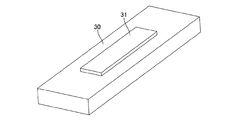
発泡シート貼付け工程S1では、磁石30の上面若しくは下面に発泡シート31を貼付ける。発泡シート31は、図4に示すように、発泡層31Aを粘着層31Bと保護フィルム31Cとにより挟んでシート状にしたものである。発泡層31Aは、発泡層31Aを構成する樹脂素材に未発泡の発泡剤を混合して、シート状に成形したものである。そして、発泡層31Aの表面となる一方の面に保護フィルム31Cを貼付け、裏面となる他方の面に粘着材(接着材等)からなる粘着層31Bを形成する。保護フィルム31Cは、磁石収容孔22への磁石30挿入時に、磁石収容孔22の入口角部や収容孔表面との接触時に引っ掛からないように、滑らかな表面を備えて摩擦係数の小さく、すべり性がよいことが望ましい。粘着層31Bの発泡層31Aとは反対の面には、図示しないが離型シートなどを貼付けて粘着層31Bを保護して供給される。
In the foam sheet attaching step S <b> 1, the
この発泡シート31は、後述する加熱工程S3において、加熱されることにより発泡層31Aに含まれている未発泡の発泡剤が発泡して、その厚さ寸法を増加させるよう機能する。発泡シート31の発泡特性は、加熱による発泡層31Aの熱膨張により、発泡シート31の総厚さが、磁石収容孔22と磁石30との間の隙間の最大値を越えるまで膨張するよう設定している。これにより、発泡シート31の熱膨張によって、磁石30を磁石収容孔22の内壁に押し付ける作用を発揮させることができる。
The foamed
また、発泡シート31が膨張する際の膨張力を、磁石収容孔22内で磁石30を移動させるに充分なものとする。ところで、発泡シート31の膨張力は、発泡シート31の面積に比例して増加する。しかし、使用する発泡シート31のコストを低減するためには、可能な限り小さい面積の発泡シート31を使用することが有効である。このため、発泡シート31のコストを低減しつつ充分な膨張力を確保できる、可能な限り小さい面積の発泡シート31を使用することが望ましい。
Further, the expansion force when the
図5は、磁石30への発泡シート31の貼付け状態を示す第1実施例である。即ち、第1実施例の貼付け状態では、発泡シート31は、貼付けるべき磁石30の上面若しくは下面の表面の幅方向寸法より小さい幅寸法に形成されている。また、発泡シート31は、磁石30の長手方向寸法に比較して、例えば、1/4〜1/6の小さい長さ寸法に形成されている。そして、磁石30の長手方向の両側領域に、夫々1枚づつ分けて貼付けている。発泡シート31の磁石30への貼り付けは、表面側に保護フィルム31Cが存在するよう粘着層31Bを磁石30側として、離型シートを剥がして露出する粘着層31Bを磁石30表面に接触させて貼付ける。
FIG. 5 is a first embodiment showing a state where the
磁石挿入工程S2では、図6に示すように、ロータコア21の磁石収容孔22へ発泡シート31を貼付けた磁石30を挿入する。図6に示す例では、ロータコア21に4個の磁石収容孔22が設けられており、夫々の磁石収容孔22に発泡シート31を貼付けた磁石30が、発泡シート31を半径方向外側に位置させて挿入した状態を示している。
In the magnet insertion step S <b> 2, as shown in FIG. 6, the
この磁石挿入工程S2においては、発泡シート31は貼付け工程S1において貼付けられたままの状態(薄肉状態)であり、磁石収容孔22への挿入が容易である。また、磁石収容孔22への磁石30の挿入時に、発泡シート31が磁石収容孔22の入口角部や収容孔表面に接触しても、発泡シート31の表面の保護フィルム31Cにより、引っ掛かることを防止できる。その際、保護フィルム31Cの表面を、滑らかな表面を備えて摩擦係数の小さく、すべり性がよいようにしておくことで、より一層挿入性を向上できる。
In the magnet insertion step S2, the
この状態においては、磁石収容孔22の半径方向内側に各磁石30が位置し、磁石収容孔22の半径方向外側に各発泡シート31が位置することは、挿入された全ての磁石30において共通している。しかし、磁石30と発泡シート31との合計厚さ寸法が、磁石収容孔22の厚さ方向の空間寸法より小さくなっているため、各磁石30は磁石収容孔22内で夫々傾いたりして取付け姿勢が均一とはなっていない。
In this state, it is common to all the inserted
加熱工程S3では、加熱炉を通過させる等により、ロータコア21を外部より加熱する。ロータコア21を外部より加熱することにより、磁石収容孔22に挿入した磁石30に貼付けた発泡シート31が、発泡層31Aに含まれる発泡剤の発泡により、厚さ方向に膨張する。この発泡シート31の膨張により、図7に示すように、保護フィルム31Cが磁石収容孔22の半径方向外側の内壁面に接触し、その反力により磁石30を磁石収容孔22の反対側の半径方向内側の内壁面に押付ける。また、磁石30が磁石収容孔22内で傾いて位置していたとしても、発泡シート31の膨張により、位置矯正されて、磁石収容孔22の反対側の半径方向内側の内壁面に押付けられる。
In the heating step S3, the
結果として、各磁石30は磁石収容孔22の反対側の半径方向内側の内壁面に接触した状態で、発泡シート31によりガタツキなく位置決めされる。即ち、発泡シート31の膨張力によって磁石30が径方向の磁石収容孔22の内壁面へ押付けられて仮固定されるため、磁石30位置のばらつきに起因するアンバランスが生じない状態とできる。
As a result, each
樹脂による固定工程S4では、ロータコア21の磁石収容孔22へ樹脂40を加圧注入して、樹脂40により磁石30を本固定する。加圧注入する樹脂40は、予め昇温軟化させて流動性を確保した状態で使用される。樹脂40の流動性を確保するために、ロータコア21を予め所定の温度に昇温させておくことが望ましい。
In the fixing step S <b> 4 with resin, the
磁石収容孔22の開放端から加圧注入された樹脂40は、樹脂入口側の磁石30と磁石収容孔22との隙間に入り、発泡シート31の幅方向外側と磁石収容孔22との隙間を通って、さらに奥の磁石収容孔22と磁石30との隙間に充填される。そして、奥側の発泡シート31の幅方向外側と磁石収容孔22との隙間を通って、さらに奥側の磁石収容孔22と磁石30との隙間に充填され、磁石収容孔22の他方の開放端まで充填されると、樹脂40の充填を止める。磁石30は磁石収容孔22内で樹脂40によってモールドされる。そして、樹脂40が冷却して凝固することにより、ロータコア21に磁石30が本固定される。
The
以上のように、本実施例によれば、ロータコア21の複数の磁石収容孔22の中に固定される磁石30の位置が、回転軸23の回転中心を基準にいずれの磁極の磁石30もその位置や取付け姿勢がばらつきなく固定させることができる。このため、ロータコア21の回転中心と複数の磁石30の合成重心との位置関係を一致させることができ、ロータ20のアンバランスを少なくでき、ロータ20完成後のアンバランスも少なくできる。
As described above, according to the present embodiment, the positions of the
この結果、バランス調整工程を設けない製造工程を実現できる。その結果、その工程で必要になる又は設定されることが望ましいとされるバランス調整用被削材の機能を持つ追加プレート等の部品を必要としないことを可能とでき、安価にロータ20を製造することができる。
As a result, a manufacturing process that does not include a balance adjustment process can be realized. As a result, it is possible to eliminate the need for parts such as an additional plate having the function of a work material for balance adjustment which is necessary or desirable to be set in the process, and manufactures the
また、磁石30への発泡シート31の貼付け状態を示す第1実施例では、磁石30の表面領域よりも小さい幅寸法の複数(2個以上)の発泡シート31を、磁石30の長手方向に並べて貼付けるようにしている。このため、発泡シート31の使用量を削減しつつ、磁石30をその長手方向の領域から各発泡シート31による均一な膨張力により磁石収容孔22の一方の壁面に押付けることができる。このため、磁石30位置及び磁石30姿勢のばらつきを低減できるとともに、発泡シート31のコストを削減することができる。
Further, in the first embodiment showing a state where the
磁石30への発泡シート31の貼付け状態は、上記した貼付け例に限定されるものでなく、以下に記載する貼付け例であってもよい。即ち、図8は磁石30への発泡シート31の貼付け状態を示す第2実施例を示すものである。本実施例の貼付け例においては、磁石30の表面領域よりも小さい幅寸法の細長い発泡シート31を、磁石30表面の長手方向に貼付けるようにしている。このようにすると、発泡シート31の粘着層31Bの粘着力が弱い場合においても、充分な貼り付け固着力を得ることができる。
The pasting state of the
本実施例においても、ロータコア21の磁石収容孔22へ挿入して、加熱工程S3により発泡シート31を膨張させると、磁石30を長手方向の広い領域から発泡シート31により磁石収容孔22の一方の壁面に押付けることができる。このため、磁石30位置及び磁石30姿勢のばらつきを低減できるとともに、発泡シート31のコストを削減することができる。また、樹脂による固定工程S4においても、磁石収容孔22に加圧注入された樹脂40は、発泡シート31の幅方向外側と磁石収容孔22との隙間に充填することができ、磁石30を磁石収容孔22内で樹脂40によってモールドすることができる。
Also in this embodiment, when the foamed
図9は、磁石30への発泡シート31の貼付け状態を示す第3実施例を示すものである。本実施例の貼付け例においては、磁石30の表面領域よりも小さい幅寸法の細長い発泡シート31を、磁石30の一方の長手方向端面とそれに連なる磁石30表面の長手方向とに跨るようにL字状に貼付けるようにしている。このようにすると、磁石挿入工程S2において磁石30を磁石収容孔22へ挿入する際に、発泡シート31が磁石収容孔22の入口角部や磁石収容孔22の壁面に接触して剥がれることを防止できる。
FIG. 9 shows a third embodiment showing a state in which the
本実施例においても、ロータコア21の磁石収容孔22へ挿入して、加熱工程S3により発泡シート31を膨張させると、磁石30を長手方向の広い領域から発泡シート31により磁石収容孔22の一方の壁面に押付けることができる。このため、磁石位置及び磁石姿勢のばらつきを低減できるとともに、発泡シート31のコストを削減することができる。また、樹脂による固定工程S4においても、磁石収容孔22に加圧注入された樹脂40は、発泡シート31の幅方向外側と磁石収容孔22との隙間に充填でき、磁石30を磁石収容孔22内で樹脂40によってモールドすることができる。
Also in this embodiment, when the foamed
図10は、磁石30への発泡シート31の貼付け状態を示す第4実施例を示すものである。本実施例の貼付け例においては、磁石30の表面領域よりも小さい幅寸法の細長い発泡シート31を、磁石30表面の幅方向両側領域において夫々長手方向に貼付けるようにしている。このようにすると、ロータコア21の磁石収容孔22へ挿入して、加熱工程S3により発泡シート31を膨張させると、磁石30を幅方向の両側領域から発泡シート31により磁石収容孔22の一方の壁面に押付けることができる。このため、磁石30が磁石収容孔22内において、幅方向の傾きを抑制できる。しかも、発泡シート31は磁石表面の幅方向両側領域において夫々長手方向に貼付けているため、磁石30の磁石収容孔22内において、長手方向の傾きも同時に抑制することができる。即ち、磁石収容孔22内の磁石30の傾きを幅方向及び長手方向の両方向において抑制することができる。従って、磁石位置及び磁石姿勢のばらつきを確実に低減できる。
FIG. 10 shows a fourth embodiment showing a state where the
本実施例においても、樹脂による固定工程S4においては、磁石収容孔22に加圧注入された樹脂40は、発泡シート31間及び発泡シート31の幅方向外側と磁石収容孔22との隙間に充填する。これにより、磁石30を磁石収容孔22内で樹脂40によってモールドすることができる。
Also in the present embodiment, in the resin fixing step S4, the
本実施形態においては、以下に記載する効果を奏することができる。 In the present embodiment, the following effects can be achieved.
(ア)本実施形態に係る回転電機用ロータの製造方法では、発泡剤を含む発泡層31Aを備える発泡シート31を、磁石30の表面に貼付ける貼付け工程S1と、発泡シート31を貼付けた磁石30を、ロータコア21に複数形成された軸方向に貫通する磁石収容孔22に、収容する磁石挿入工程S2と、ロータコア21を加熱することにより発泡シート31を加熱し、発泡シート31の発泡層31Aを膨張させて、磁石30を磁石収容孔22の壁面に押付ける加熱工程S3と、を備える。即ち、発泡シート31の膨張力によって、各磁石収容孔22内の磁石30は、同じ方向に押圧されて固定されるため、樹脂40の注入前において、磁石位置のばらつきを低減できる。このため、固定工程S4により磁石収容孔22に溶融した樹脂40を注入して磁石30を樹脂40でモールドすると、全ての磁石収容孔22内の磁石30の取付け姿勢を、ばらつきなく均一とすることを補償することができる。
(A) In the method for manufacturing a rotor for a rotating electrical machine according to the present embodiment, a sticking step S1 for sticking a
(イ)本実施形態に係る回転電機用ロータ20では、ロータコア21に複数形成された軸方向に貫通する磁石収容孔22に、発泡剤を含む発泡層31Aを備える発泡シート31と、発泡剤の発泡による発泡シート31の膨張により磁石収容孔22の壁面に押付けられた磁石30と、発泡シート31及び磁石30と磁石収容孔22との隙間に充填された樹脂40と、を収容してなることを特徴とする。即ち、ロータコア21の複数の磁石収容孔22の中に固定される磁石30の位置が、回転軸23の回転中心を基準にいずれの磁極の磁石30もその位置や取付け姿勢がばらつきなく固定させることができる。このため、ロータコア21の回転中心と複数の磁石30の合成重心との位置関係を一致させることができ、ロータ20のアンバランスを少なくでき、ロータ20完成後のアンバランスも少なくできる。この結果、バランス調整工程を設けない製造工程を実現できる。その結果、その工程で必要になる又は設定されることが望ましいとされるバランス調整用被削材の機能を持つ追加プレート等の部品を必要としないことを可能とでき、安価にロータ20を製造することができる。
(B) In the
(ウ)第1実施例の貼付け例においては、磁石30の表面に貼付けられる発泡シート31は、当該表面の幅寸法より小さい幅寸法より小さく形成されて、複数枚が磁石表面の長手方向に並べて貼付けられている。このため、発泡シート31の使用量を削減しつつ、磁石30をその長手方向の領域から各発泡シート31による均一な膨張力により磁石収容孔22の一方の壁面に押付けることができる。このため、磁石位置及び磁石姿勢のばらつきを低減できるとともに、発泡シート31のコストを削減することができる。
(C) In the pasting example of the first embodiment, the
(エ)第2実施例の貼付け例においては、磁石30の表面に貼付けられる発泡シート31は、当該表面の幅寸法より小さい幅寸法を備えて細長く形成されて、磁石30表面の長手方向に貼付けられている。このようにすると、発泡シート31の粘着層31Bの粘着力が弱い場合においても、充分な貼り付け固着力を得ることができる。
(D) In the pasting example of the second embodiment, the
(オ)第3実施例の貼付け例においては、磁石30の表面に貼付けられる発泡シート31は、当該表面の幅寸法より小さい幅寸法を備えて細長く形成される。そして、磁石30の一方の長手方向端面とそれに連なる磁石30表面の長手方向とに跨るようにL字状に貼付けられている。このようにすると、磁石挿入工程S2において磁石30を磁石収容孔22へ挿入する際に、発泡シート31が磁石収容孔22の入口角部や磁石収容孔22の壁面に接触して剥がれることを防止できる。
(E) In the pasting example of the third embodiment, the
(カ)第4実施例の貼付け例においては、磁石30の表面に貼付けられる発泡シート31は、当該表面の幅寸法より小さい幅寸法を備えて細長く形成されて、磁石30表面の幅方向両側領域において夫々磁石30表面の長手方向に貼付けられている。このようにすると、ロータコア21の磁石収容孔22へ挿入して、加熱工程S3により発泡シート31を膨張させると、磁石30を幅方向の両側領域から発泡シート31により磁石収容孔22の一方の壁面に押付けることができる。このため、磁石30が磁石収容孔22内において、幅方向の傾きを抑制できる。しかも、発泡シート31は磁石30表面の幅方向両側領域において夫々長手方向に貼付けているため、磁石30の磁石収容孔22内において、長手方向の傾きも同時に抑制することができる。即ち、磁石収容孔22内の磁石30の傾きを幅方向及び長手方向の両方向において抑制することができる。
(F) In the pasting example of the fourth embodiment, the
S1 貼付け工程
S2 磁石挿入工程
S3 加熱工程
S4 固定工程
20 ロータ
21 ロータコア
22 磁石収容孔
23 回転軸
30 磁石、永久磁石
31 発泡シート
31A 発泡層
31B 粘着層
31C 保護フィルム
40 樹脂
S1 Application process S2 Magnet insertion process S3 Heating process
Claims (6)
前記発泡シートを貼付けた磁石を、ロータコアに複数形成された軸方向に貫通する磁石収容孔に、収容する磁石挿入工程と、
前記ロータコアを加熱することにより前記発泡シートを加熱し、前記発泡シートの発泡層を膨張させて、前記磁石を磁石収容孔の壁面に押付ける加熱工程と、
前記磁石収容孔に溶融樹脂を注入して、前記磁石を樹脂でモールドする固定工程と、を備えることを特徴とする回転電機用ロータの製造方法。 A pasting step of pasting a foam sheet comprising a foam layer containing a foaming agent on the surface of the magnet;
A magnet insertion step of accommodating the magnet on which the foam sheet is affixed in a magnet accommodation hole penetrating in the axial direction formed in the rotor core; and
Heating the foam core by heating the rotor core, expanding the foam layer of the foam sheet, and pressing the magnet against the wall surface of the magnet housing hole; and
A method of manufacturing a rotor for a rotating electrical machine, comprising: a fixing step of injecting molten resin into the magnet housing hole and molding the magnet with resin.
発泡剤を含む発泡層を備える発泡シートと、
前記発泡剤の発泡による発泡シートの膨張により前記磁石収容孔の壁面に押付けられた磁石と、
前記発泡シート及び磁石と磁石収容孔との隙間に充填された樹脂材と、を収容してなることを特徴とする回転電機用ロータ。 In the magnet housing hole penetrating in the axial direction formed in the rotor core,
A foam sheet comprising a foam layer containing a foaming agent;
A magnet pressed against the wall surface of the magnet accommodation hole by expansion of a foam sheet by foaming of the foaming agent;
A rotor for a rotating electrical machine comprising: the foam sheet and a resin material filled in a gap between the magnet and the magnet housing hole.
Priority Applications (1)
| Application Number | Priority Date | Filing Date | Title |
|---|---|---|---|
| JP2013165362A JP6322924B2 (en) | 2013-08-08 | 2013-08-08 | Rotating electrical machine rotor and method of manufacturing the same |
Applications Claiming Priority (1)
| Application Number | Priority Date | Filing Date | Title |
|---|---|---|---|
| JP2013165362A JP6322924B2 (en) | 2013-08-08 | 2013-08-08 | Rotating electrical machine rotor and method of manufacturing the same |
Publications (2)
| Publication Number | Publication Date |
|---|---|
| JP2015035888A JP2015035888A (en) | 2015-02-19 |
| JP6322924B2 true JP6322924B2 (en) | 2018-05-16 |
Family
ID=52544052
Family Applications (1)
| Application Number | Title | Priority Date | Filing Date |
|---|---|---|---|
| JP2013165362A Active JP6322924B2 (en) | 2013-08-08 | 2013-08-08 | Rotating electrical machine rotor and method of manufacturing the same |
Country Status (1)
| Country | Link |
|---|---|
| JP (1) | JP6322924B2 (en) |
Cited By (1)
| Publication number | Priority date | Publication date | Assignee | Title |
|---|---|---|---|---|
| CN110492703A (en) * | 2019-08-24 | 2019-11-22 | 中船重工电机科技股份有限公司 | The stickup protective tooling and protection method of attaching of permanent-magnetic electric machine rotor magnet steel |
Families Citing this family (12)
| Publication number | Priority date | Publication date | Assignee | Title |
|---|---|---|---|---|
| JP6369420B2 (en) | 2015-08-07 | 2018-08-08 | トヨタ自動車株式会社 | Manufacturing method of rotor |
| JP6383745B2 (en) * | 2016-03-10 | 2018-08-29 | 本田技研工業株式会社 | Manufacturing method of rotor of rotating electrical machine and rotor of rotating electrical machine |
| JP6685175B2 (en) * | 2016-05-24 | 2020-04-22 | 日立オートモティブシステムズ株式会社 | Rotating electric machine |
| CN109643923B (en) * | 2016-09-07 | 2020-11-03 | 爱信艾达株式会社 | Method for manufacturing rotor |
| JP2018067978A (en) * | 2016-10-17 | 2018-04-26 | 日立オートモティブシステムズ株式会社 | Rotary electric machine and manufacturing method of the same |
| CN110754031B (en) * | 2018-10-11 | 2021-05-11 | 黑田精工株式会社 | Rotor core holding tool, and device and method for manufacturing magnet-embedded core |
| JP7079763B2 (en) * | 2019-12-23 | 2022-06-02 | 本田技研工業株式会社 | How to manufacture rotors for rotary electric machines, permanent magnet assemblies, and rotors for rotary electric machines |
| JP2021141682A (en) * | 2020-03-04 | 2021-09-16 | 日立Astemo株式会社 | Rotary electric machine and rotator of the same |
| JP7267614B2 (en) * | 2020-06-30 | 2023-05-02 | アピックヤマダ株式会社 | Magnet fixing method |
| CN111934455B (en) * | 2020-09-19 | 2021-06-04 | 浙江西菱股份有限公司 | Three-phase permanent magnet synchronous variable frequency motor |
| JP7524821B2 (en) | 2021-04-16 | 2024-07-30 | トヨタ自動車株式会社 | Rotor manufacturing method |
| JP7312880B1 (en) * | 2022-04-20 | 2023-07-21 | 株式会社メタルアート | LAMINATED CORE AND METHOD FOR MANUFACTURING LAMINATED CORE |
Family Cites Families (8)
| Publication number | Priority date | Publication date | Assignee | Title |
|---|---|---|---|---|
| JP2006311782A (en) * | 2005-03-30 | 2006-11-09 | Toyota Motor Corp | Rotor and method for manufacturing the same |
| JP2007174872A (en) * | 2005-12-26 | 2007-07-05 | Nitto Shinko Kk | Heated foamed sheet for bonding motor magnetic member |
| JP4850528B2 (en) * | 2006-02-08 | 2012-01-11 | トヨタ自動車株式会社 | Manufacturing method of rotor |
| JP5298905B2 (en) * | 2009-02-09 | 2013-09-25 | 日産自動車株式会社 | Manufacturing method of split permanent magnet and electric motor using the split permanent magnet |
| EP2249460B1 (en) * | 2009-05-05 | 2012-03-07 | Iro Ab | Positioning substrate and permanent magnet rotor |
| JP5609330B2 (en) * | 2010-07-05 | 2014-10-22 | 日産自動車株式会社 | Rotating electric machine and method of manufacturing rotating electric machine |
| JP5716377B2 (en) * | 2010-12-17 | 2015-05-13 | アイシン精機株式会社 | Rotating electric machine |
| JP2013132116A (en) * | 2011-12-21 | 2013-07-04 | Aisin Seiki Co Ltd | Rotary electric machine |
-
2013
- 2013-08-08 JP JP2013165362A patent/JP6322924B2/en active Active
Cited By (2)
| Publication number | Priority date | Publication date | Assignee | Title |
|---|---|---|---|---|
| CN110492703A (en) * | 2019-08-24 | 2019-11-22 | 中船重工电机科技股份有限公司 | The stickup protective tooling and protection method of attaching of permanent-magnetic electric machine rotor magnet steel |
| CN110492703B (en) * | 2019-08-24 | 2021-07-09 | 中船重工电机科技股份有限公司 | Pasting protection tool and method for permanent magnet motor rotor magnetic steel |
Also Published As
| Publication number | Publication date |
|---|---|
| JP2015035888A (en) | 2015-02-19 |
Similar Documents
| Publication | Publication Date | Title |
|---|---|---|
| JP6322924B2 (en) | Rotating electrical machine rotor and method of manufacturing the same | |
| EP1851844B1 (en) | Rotor and method of manufacturing | |
| TWI596868B (en) | Permanent magnet type motor and permanent magnet type motor manufacturing method | |
| JP6095827B1 (en) | Manufacturing method of rotor for rotating electrical machine | |
| US20130127283A1 (en) | Rotor of an electric motor and manufacturing method of same | |
| US20090108686A1 (en) | Rotor of brushless (bl) motor | |
| WO2017170982A1 (en) | Rotor for rotary machine | |
| JP4968928B2 (en) | Permanent magnet motor and manufacturing method thereof | |
| JP2007089291A (en) | Permanent magnet rotating electric machine | |
| JP7019420B2 (en) | Brushless DC electric motor | |
| CN108781011B (en) | Method for manufacturing rotor | |
| JP2016127771A (en) | Rotary electric machine rotor | |
| JP2007325405A (en) | Rotator of inner-rotor motor and manufacturing method thereof | |
| JP2007060860A (en) | Permanent magnet type rotor | |
| JP6707392B2 (en) | Rotor manufacturing method | |
| JP6601568B2 (en) | Manufacturing method of rotor | |
| JP6759893B2 (en) | Rotating electric rotor | |
| JP5033320B2 (en) | Method for manufacturing stator of electric motor | |
| JP2012105543A (en) | Stator for electric motor | |
| KR20140115442A (en) | A motor | |
| JP2023054939A (en) | Stator manufacturing method | |
| JP2009225607A (en) | Permanent magnet rotor and manufacturing method therefor | |
| JP6876692B2 (en) | Rotating machine | |
| JP2013099048A (en) | Rotor of permanent magnet rotary electric machine and permanent magnet rotary electric machine | |
| JP2018107929A (en) | Motor rotor and manufacturing method thereof |
Legal Events
| Date | Code | Title | Description |
|---|---|---|---|
| A621 | Written request for application examination |
Free format text: JAPANESE INTERMEDIATE CODE: A621 Effective date: 20160325 |
|
| RD02 | Notification of acceptance of power of attorney |
Free format text: JAPANESE INTERMEDIATE CODE: A7422 Effective date: 20161205 |
|
| A131 | Notification of reasons for refusal |
Free format text: JAPANESE INTERMEDIATE CODE: A131 Effective date: 20170131 |
|
| A977 | Report on retrieval |
Free format text: JAPANESE INTERMEDIATE CODE: A971007 Effective date: 20170131 |
|
| A521 | Written amendment |
Free format text: JAPANESE INTERMEDIATE CODE: A523 Effective date: 20170329 |
|
| A131 | Notification of reasons for refusal |
Free format text: JAPANESE INTERMEDIATE CODE: A131 Effective date: 20170815 |
|
| TRDD | Decision of grant or rejection written | ||
| A01 | Written decision to grant a patent or to grant a registration (utility model) |
Free format text: JAPANESE INTERMEDIATE CODE: A01 Effective date: 20180313 |
|
| A61 | First payment of annual fees (during grant procedure) |
Free format text: JAPANESE INTERMEDIATE CODE: A61 Effective date: 20180326 |
|
| R151 | Written notification of patent or utility model registration |
Ref document number: 6322924 Country of ref document: JP Free format text: JAPANESE INTERMEDIATE CODE: R151 |