JP6300033B2 - Image processing apparatus and method - Google Patents
Image processing apparatus and method Download PDFInfo
- Publication number
- JP6300033B2 JP6300033B2 JP2014554323A JP2014554323A JP6300033B2 JP 6300033 B2 JP6300033 B2 JP 6300033B2 JP 2014554323 A JP2014554323 A JP 2014554323A JP 2014554323 A JP2014554323 A JP 2014554323A JP 6300033 B2 JP6300033 B2 JP 6300033B2
- Authority
- JP
- Japan
- Prior art keywords
- unit
- layer
- image
- decoding
- parameter
- Prior art date
- Legal status (The legal status is an assumption and is not a legal conclusion. Google has not performed a legal analysis and makes no representation as to the accuracy of the status listed.)
- Active
Links
- 238000000034 method Methods 0.000 title claims description 271
- 238000012545 processing Methods 0.000 title claims description 194
- 230000008569 process Effects 0.000 claims description 210
- 239000000872 buffer Substances 0.000 claims description 178
- 238000003672 processing method Methods 0.000 claims description 3
- 230000000153 supplemental effect Effects 0.000 claims description 3
- 239000010410 layer Substances 0.000 description 714
- 238000004364 calculation method Methods 0.000 description 97
- 230000003139 buffering effect Effects 0.000 description 96
- 238000009825 accumulation Methods 0.000 description 94
- 239000012536 storage buffer Substances 0.000 description 84
- 230000005540 biological transmission Effects 0.000 description 57
- 238000013139 quantization Methods 0.000 description 54
- 230000015654 memory Effects 0.000 description 48
- 238000004891 communication Methods 0.000 description 43
- 238000012544 monitoring process Methods 0.000 description 42
- 238000010586 diagram Methods 0.000 description 38
- 238000007726 management method Methods 0.000 description 37
- 238000003384 imaging method Methods 0.000 description 32
- 230000002123 temporal effect Effects 0.000 description 29
- 230000006870 function Effects 0.000 description 24
- 230000008707 rearrangement Effects 0.000 description 21
- 230000004044 response Effects 0.000 description 20
- 230000006835 compression Effects 0.000 description 19
- 238000007906 compression Methods 0.000 description 19
- 238000005516 engineering process Methods 0.000 description 19
- 238000006243 chemical reaction Methods 0.000 description 17
- 238000013500 data storage Methods 0.000 description 17
- 239000000284 extract Substances 0.000 description 12
- 230000003287 optical effect Effects 0.000 description 12
- 230000005236 sound signal Effects 0.000 description 10
- 230000009467 reduction Effects 0.000 description 6
- 239000011229 interlayer Substances 0.000 description 5
- 230000003044 adaptive effect Effects 0.000 description 4
- 230000009466 transformation Effects 0.000 description 4
- 230000001413 cellular effect Effects 0.000 description 3
- 238000012937 correction Methods 0.000 description 3
- 239000004065 semiconductor Substances 0.000 description 3
- FMYKJLXRRQTBOR-UBFHEZILSA-N (2s)-2-acetamido-4-methyl-n-[4-methyl-1-oxo-1-[[(2s)-1-oxohexan-2-yl]amino]pentan-2-yl]pentanamide Chemical group CCCC[C@@H](C=O)NC(=O)C(CC(C)C)NC(=O)[C@H](CC(C)C)NC(C)=O FMYKJLXRRQTBOR-UBFHEZILSA-N 0.000 description 2
- 238000000605 extraction Methods 0.000 description 2
- 239000011159 matrix material Substances 0.000 description 2
- 238000012986 modification Methods 0.000 description 2
- 230000004048 modification Effects 0.000 description 2
- 239000002356 single layer Substances 0.000 description 2
- 230000009471 action Effects 0.000 description 1
- 230000003321 amplification Effects 0.000 description 1
- 230000015556 catabolic process Effects 0.000 description 1
- 230000010267 cellular communication Effects 0.000 description 1
- 230000008859 change Effects 0.000 description 1
- 230000000295 complement effect Effects 0.000 description 1
- 238000006731 degradation reaction Methods 0.000 description 1
- 230000001934 delay Effects 0.000 description 1
- 238000005401 electroluminescence Methods 0.000 description 1
- 230000006872 improvement Effects 0.000 description 1
- 210000003127 knee Anatomy 0.000 description 1
- 239000004973 liquid crystal related substance Substances 0.000 description 1
- 230000007246 mechanism Effects 0.000 description 1
- 229910044991 metal oxide Inorganic materials 0.000 description 1
- 150000004706 metal oxides Chemical class 0.000 description 1
- 238000003199 nucleic acid amplification method Methods 0.000 description 1
- 230000008520 organization Effects 0.000 description 1
- 238000007639 printing Methods 0.000 description 1
- LSEKLPKUWRDLKY-UHFFFAOYSA-N protoleucomelone Chemical compound C1=CC(OC(=O)C)=CC=C1C1=C(OC(C)=O)C(OC(C)=O)=C(C=2C(=CC(OC(C)=O)=C(OC(C)=O)C=2)O2)C2=C1OC(C)=O LSEKLPKUWRDLKY-UHFFFAOYSA-N 0.000 description 1
- 230000002441 reversible effect Effects 0.000 description 1
- 238000010187 selection method Methods 0.000 description 1
- 239000007787 solid Substances 0.000 description 1
Images


Classifications
-
- G—PHYSICS
- G06—COMPUTING; CALCULATING OR COUNTING
- G06T—IMAGE DATA PROCESSING OR GENERATION, IN GENERAL
- G06T1/00—General purpose image data processing
-
- G—PHYSICS
- G06—COMPUTING; CALCULATING OR COUNTING
- G06T—IMAGE DATA PROCESSING OR GENERATION, IN GENERAL
- G06T9/00—Image coding
-
- H—ELECTRICITY
- H04—ELECTRIC COMMUNICATION TECHNIQUE
- H04N—PICTORIAL COMMUNICATION, e.g. TELEVISION
- H04N19/00—Methods or arrangements for coding, decoding, compressing or decompressing digital video signals
- H04N19/10—Methods or arrangements for coding, decoding, compressing or decompressing digital video signals using adaptive coding
- H04N19/134—Methods or arrangements for coding, decoding, compressing or decompressing digital video signals using adaptive coding characterised by the element, parameter or criterion affecting or controlling the adaptive coding
- H04N19/146—Data rate or code amount at the encoder output
- H04N19/152—Data rate or code amount at the encoder output by measuring the fullness of the transmission buffer
-
- H—ELECTRICITY
- H04—ELECTRIC COMMUNICATION TECHNIQUE
- H04N—PICTORIAL COMMUNICATION, e.g. TELEVISION
- H04N19/00—Methods or arrangements for coding, decoding, compressing or decompressing digital video signals
- H04N19/10—Methods or arrangements for coding, decoding, compressing or decompressing digital video signals using adaptive coding
- H04N19/169—Methods or arrangements for coding, decoding, compressing or decompressing digital video signals using adaptive coding characterised by the coding unit, i.e. the structural portion or semantic portion of the video signal being the object or the subject of the adaptive coding
- H04N19/187—Methods or arrangements for coding, decoding, compressing or decompressing digital video signals using adaptive coding characterised by the coding unit, i.e. the structural portion or semantic portion of the video signal being the object or the subject of the adaptive coding the unit being a scalable video layer
-
- H—ELECTRICITY
- H04—ELECTRIC COMMUNICATION TECHNIQUE
- H04N—PICTORIAL COMMUNICATION, e.g. TELEVISION
- H04N19/00—Methods or arrangements for coding, decoding, compressing or decompressing digital video signals
- H04N19/30—Methods or arrangements for coding, decoding, compressing or decompressing digital video signals using hierarchical techniques, e.g. scalability
-
- H—ELECTRICITY
- H04—ELECTRIC COMMUNICATION TECHNIQUE
- H04N—PICTORIAL COMMUNICATION, e.g. TELEVISION
- H04N19/00—Methods or arrangements for coding, decoding, compressing or decompressing digital video signals
- H04N19/46—Embedding additional information in the video signal during the compression process
- H04N19/463—Embedding additional information in the video signal during the compression process by compressing encoding parameters before transmission
-
- H—ELECTRICITY
- H04—ELECTRIC COMMUNICATION TECHNIQUE
- H04N—PICTORIAL COMMUNICATION, e.g. TELEVISION
- H04N19/00—Methods or arrangements for coding, decoding, compressing or decompressing digital video signals
- H04N19/50—Methods or arrangements for coding, decoding, compressing or decompressing digital video signals using predictive coding
- H04N19/597—Methods or arrangements for coding, decoding, compressing or decompressing digital video signals using predictive coding specially adapted for multi-view video sequence encoding
-
- H—ELECTRICITY
- H04—ELECTRIC COMMUNICATION TECHNIQUE
- H04N—PICTORIAL COMMUNICATION, e.g. TELEVISION
- H04N19/00—Methods or arrangements for coding, decoding, compressing or decompressing digital video signals
- H04N19/70—Methods or arrangements for coding, decoding, compressing or decompressing digital video signals characterised by syntax aspects related to video coding, e.g. related to compression standards
-
- H—ELECTRICITY
- H04—ELECTRIC COMMUNICATION TECHNIQUE
- H04N—PICTORIAL COMMUNICATION, e.g. TELEVISION
- H04N19/00—Methods or arrangements for coding, decoding, compressing or decompressing digital video signals
- H04N19/10—Methods or arrangements for coding, decoding, compressing or decompressing digital video signals using adaptive coding
- H04N19/134—Methods or arrangements for coding, decoding, compressing or decompressing digital video signals using adaptive coding characterised by the element, parameter or criterion affecting or controlling the adaptive coding
- H04N19/162—User input
Landscapes
- Engineering & Computer Science (AREA)
- Multimedia (AREA)
- Signal Processing (AREA)
- Physics & Mathematics (AREA)
- General Physics & Mathematics (AREA)
- Theoretical Computer Science (AREA)
- Compression Or Coding Systems Of Tv Signals (AREA)
- Two-Way Televisions, Distribution Of Moving Picture Or The Like (AREA)
Description
本開示は画像処理装置および方法に関し、特に、スケーラブル符号化において、正しいタイミングで復号処理を行うことができるようにした画像処理装置および方法に関する。 The present disclosure relates to an image processing apparatus and method, and more particularly, to an image processing apparatus and method capable of performing decoding processing at correct timing in scalable coding.
近年、画像情報をデジタルとして取り扱い、その際、効率の高い情報の伝送、蓄積を目的とし、画像情報特有の冗長性を利用して、離散コサイン変換等の直交変換と動き補償により圧縮する符号化方式を採用して画像を圧縮符号する装置が普及しつつある。この符号化方式には、例えば、MPEG(Moving Picture Experts Group)やH.264及びMPEG-4 Part10 Advanced Video Coding(以下 AVCと記す)などがある。
In recent years, image information has been handled as digital data, and at that time, for the purpose of efficient transmission and storage of information, encoding is performed by orthogonal transform such as discrete cosine transform and motion compensation using redundancy unique to image information. An apparatus that employs a method to compress and code an image is becoming widespread. Examples of this encoding method include MPEG (Moving Picture Experts Group) and H.264. H.264 and MPEG-4
そして、現在、H.264/AVCより更なる符号化効率の向上を目的として、ITU-TとISO/IECとの共同の標準化団体であるJCTVC (Joint Collaboration Team - Video Coding) により、HEVC (High Efficiency Video Coding) と呼ばれる符号化方式の標準化が進められている。また、そのドラフトとして非特許文献1が発行されている。
And now H. It is called HEVC (High Efficiency Video Coding) by JCTVC (Joint Collaboration Team-Video Coding), a joint standardization organization of ITU-T and ISO / IEC, for the purpose of further improving coding efficiency than H.264 / AVC. Standardization of the encoding method is underway. Further,
ところで、これまでの、MPEG-2やAVCといった画像符号化方式は、画像を複数のレイヤに階層化して符号化するスケーラビリティ(scalability)機能を有していた。 By the way, the conventional image encoding methods such as MPEG-2 and AVC have a scalability function for encoding an image by layering a plurality of layers.
すなわち、例えば携帯電話機のような、処理能力の低い端末に対しては、ベースレイヤ(base layer)のみの画像圧縮情報を伝送し、空間時間解像度の低い、或いは、画質の良くない動画像を再生し、テレビやパーソナルコンピュータのような、処理能力の高い端末に対しては、ベースレイヤ(base layer)に加えて、エンハンスメントレイヤ(enhancement layer)の画像圧縮情報を伝送し、空間時間解像度の高い、或いは、画質の高い動画像を再生するといったように、トランスコード処理を行うことなく、端末やネットワークの能力に応じた画像圧縮情報を、サーバから送信することが可能となる。 That is, for example, to a terminal with low processing capability, such as a mobile phone, image compression information of only the base layer is transmitted, and a moving image with low spatiotemporal resolution or poor image quality is reproduced. However, for terminals with high processing capability such as televisions and personal computers, in addition to the base layer (base layer), image compression information of the enhancement layer (enhancement layer) is transmitted, and the spatial and temporal resolution is high. Alternatively, it is possible to transmit image compression information according to the capabilities of the terminal and the network from the server without performing transcoding processing, such as playing a moving image with high image quality.
HEVCにおいては、画像圧縮情報の復号処理を行う際、バッファのオーバフローやアンダーフローが起きないよう、HRD(Hypothetical Reference Decoder)パラメータを指定することが可能である。特に、スケーラブル符号化を行う際には、階層毎にHRDパラメータを指定することができる(非特許文献2参照)。 In HEVC, it is possible to specify an HRD (Hypothetical Reference Decoder) parameter so that buffer overflow and underflow do not occur when decoding processing of compressed image information. In particular, when performing scalable coding, an HRD parameter can be specified for each layer (see Non-Patent Document 2).
しかしながら、階層毎、もしくは、そのサブ階層の1つである時間階層毎に、HRDパラメータを指定する場合、その復号処理が、単一の復号装置により行われるものであるのか、複数の復号装置により行われるものであるのかわからなかった。 However, when the HRD parameter is designated for each hierarchy or for each time hierarchy that is one of the sub-hierarchies, whether the decoding process is performed by a single decoding apparatus or by a plurality of decoding apparatuses I didn't know what was going on.
本開示は、このような状況に鑑みてなされたものであり、正しいタイミングで復号処理を行うことができるものである。 The present disclosure has been made in view of such a situation, and can perform a decoding process at a correct timing.
本開示の一側面の画像処理装置は、少なくとも1つのレイヤを有する画像が符号化されたビットリームと、デコーダバッファを管理するパラメータが、当該レイヤのみの復号処理を行うためのパラメータであること、および当該レイヤとそれ以下のレイヤとを含む復号処理を行うためのパラメータであることの少なくとも1つを示す情報であるレイヤ毎のバッファ管理パラメータ情報とを受け取る受け取り部と、前記レイヤ毎のバッファ管理パラメータ情報に基づいて、前記受け取り部により受け取られた前記ビットストリームを復号して、画像を生成する復号部とを備える。 According to an embodiment of the present disclosure, bit stream which the image is encoded with at least one layer, the parameters for managing the decoder buffer is a parameter for performing the decoding process of the layer alone, A receiving unit for receiving buffer management parameter information for each layer, which is information indicating at least one of parameters for performing decoding processing including the layer and the layers below, and buffer management for each layer based on the parameter information, and decoding the bit stream received by the receiving unit, and a decoding unit that generates an image.
前記レイヤは、サブレイヤを含むことができる。 The layer may include a sublayer.
前記レイヤは、マルチビュー符号化のビューである。 The layer is a view of multi-view coding.
前記レイヤは、スケーラブル符号化のレイヤである。 The layer is a layer for scalable coding.
前記バッファ管理パラメータ情報は、SEI(Supplemental Enhancement Information)に記述されている。 The buffer management parameter information is described in SEI (Supplemental Enhancement Information).
前記バッファ管理パラメータ情報は、buffering_period_SEIに記述されている。 The buffer management parameter information is described in buffering_period_SEI.
前記当該レイヤのみの復号処理を行うためのパラメータであるデコーダバッファを管理するパラメータの有無を示す情報であるパラメータ有無情報は、vps(video parameter set)_extensionに記述されている。 Parameter presence / absence information, which is information indicating the presence / absence of a parameter for managing a decoder buffer, which is a parameter for performing decoding processing for only the layer , is described in vps (video parameter set) _extension.
前記受け取り部は、前記当該レイヤ以下のレイヤがAVC(MPEG-4 Part10 Advanced Video Coding)符号化により符号化されていることを示すAVCフラグと、前記デコーダバッファを管理するパラメータが、当該レイヤのみの復号処理を行うためのパラメータであることを示す情報であるレイヤ毎のバッファ管理パラメータ情報とを受け取ることができる。
The receiving unit includes an AVC flag indicating that a layer below the layer is encoded by AVC (MPEG-4
本開示の一側面の画像処理方法は、画像処理装置が、少なくとも1つのレイヤを有する画像が符号化されたビットリームと、デコーダバッファを管理するパラメータが、当該レイヤのみの復号処理を行うためのパラメータであること、および当該レイヤとそれ以下のレイヤとを含む復号処理を行うためのパラメータであることの少なくとも1つを示す情報であるレイヤ毎のバッファ管理パラメータ情報とを受け取り、前記レイヤ毎のバッファ管理パラメータ情報に基づいて、受け取られた前記ビットストリームを復号して、画像を生成する。 According to an image processing method of one aspect of the present disclosure, an image processing apparatus is configured to perform a decoding process on only a layer in which a bitstream obtained by encoding an image having at least one layer and a parameter for managing a decoder buffer are performed. it is a parameter, and receiving the said layer and less buffer management parameter information for each layer, which is information indicating at least one of that is a parameter for decoding process including a layer, for each of the layers based on the buffer management parameter information, and decoding the bit stream received, and generates an image.
本開示の一側面においては、少なくとも1つのレイヤを有する画像が符号化されたビットリームと、デコーダバッファを管理するパラメータが、当該レイヤのみの復号処理を行うためのパラメータであること、および当該レイヤとそれ以下のレイヤとを含む復号処理を行うためのパラメータであることの少なくとも1つを示す情報であるレイヤ毎のバッファ管理パラメータ情報とが受け取られる。そして、前記レイヤ毎のバッファ管理パラメータ情報に基づいて、受け取られた前記ビットストリームを復号して、画像が生成される。 In one aspect of the present disclosure, that the image having at least one layer and a bit stream that is encoded, parameters governing the decoder buffer is a parameter for performing the decoding process of the layer alone, and the layers And buffer management parameter information for each layer, which is information indicating at least one of the parameters for performing the decoding process including the layers below it. Then, based on the buffer management parameter information for each of the layers, to decode the bit stream received, an image is generated.
なお、上述の画像処理装置は、独立した装置であっても良いし、1つの画像符号化装置または画像復号装置を構成している内部ブロックであってもよい。 Note that the above-described image processing device may be an independent device, or may be an internal block constituting one image encoding device or image decoding device.
本開示の一側面によれば、画像を復号することができる。特に、正しいタイミングで復号処理を行うことができる。 According to one aspect of the present disclosure, an image can be decoded. In particular, the decoding process can be performed at the correct timing.
以下、本開示を実施するための形態(以下実施の形態とする)について説明する。なお、説明は以下の順序で行う。
0.概要
1.第1の実施の形態(画像符号化装置)
2.第2の実施の形態(画像復号装置)
3.第3の実施の形態(シンタクスの例)
4.第4の実施の形態(buffering_period_SEIの例)
5.第5の実施の形態(AVCフラグの例)
6.第6の実施の形態(多視点画像符号化装置・多視点画像復号装置)
7.第7の実施の形態(コンピュータ)
8.応用例
9.スケーラブル符号化の応用例Hereinafter, modes for carrying out the present disclosure (hereinafter referred to as embodiments) will be described. The description will be given in the following order.
0.
2. Second embodiment (image decoding apparatus)
3. Third embodiment (syntax example)
4). Fourth embodiment (example of buffering_period_SEI)
5. Fifth embodiment (example of AVC flag)
6). Sixth embodiment (multi-view image encoding device / multi-view image decoding device)
7). Seventh embodiment (computer)
8). Application example 9. Application examples of scalable coding
<0.概要>
<符号化方式>
以下においては、HEVC(High Efficiency Video Coding)方式の画像符号化・復号に適用する場合を例に、本技術を説明する。<0. Overview>
<Encoding method>
In the following, the present technology will be described by taking as an example the case of application to HEVC (High Efficiency Video Coding) image encoding / decoding.
<コーディングユニット>
AVC(Advanced Video Coding)方式においては、マクロブロックとサブマクロブロックによる階層構造が規定されている。しかしながら、16画素×16画素のマクロブロックでは、次世代符号化方式の対象となるような、UHD(Ultra High Definition;4000画素×2000画素)といった大きな画枠に対して最適ではない。<Coding unit>
In the AVC (Advanced Video Coding) method, a hierarchical structure is defined by macroblocks and sub-macroblocks. However, a macroblock of 16 pixels × 16 pixels is not optimal for a large image frame such as UHD (Ultra High Definition; 4000 pixels × 2000 pixels), which is a target of the next generation encoding method.
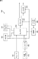
これに対して、HEVC方式においては、図1に示されるように、コーディングユニット(CU(Coding Unit))が規定されている。 On the other hand, in the HEVC scheme, as shown in FIG. 1, a coding unit (CU (Coding Unit)) is defined.
CUは、Coding Tree Block(CTB)とも呼ばれ、AVC方式におけるマクロブロックと同様の役割を果たす、ピクチャ単位の画像の部分領域である。後者は、16×16画素の大きさに固定されているのに対し、前者の大きさは固定されておらず、それぞれのシーケンスにおいて、画像圧縮情報中において指定されることになる。 CU is also called a Coding Tree Block (CTB), and is a partial area of a picture unit image that plays the same role as a macroblock in the AVC method. The latter is fixed to a size of 16 × 16 pixels, whereas the size of the former is not fixed, and is specified in the image compression information in each sequence.
例えば、出力となる符号化データに含まれるシーケンスパラメータセット(SPS(Sequence Parameter Set))において、CUの最大サイズ(LCU(Largest Coding Unit))と最小サイズ(SCU(Smallest Coding Unit))が規定される。 For example, in the sequence parameter set (SPS (Sequence Parameter Set)) included in the encoded data to be output, the maximum size (LCU (Largest Coding Unit)) and minimum size (SCU (Smallest Coding Unit)) of the CU are specified. The
それぞれのLCU内においては、SCUのサイズを下回らない範囲で、split-flag=1とすることにより、より小さなサイズのCUに分割することができる。図1の例では、LCUの大きさが128であり、最大階層深度が5となる。2N×2Nの大きさのCUは、split_flagの値が「1」である時、1つ下の階層となる、N×Nの大きさのCUに分割される。 Within each LCU, split-flag = 1 can be divided into smaller CUs within a range that does not fall below the SCU size. In the example of FIG. 1, the LCU size is 128 and the maximum hierarchical depth is 5. When the value of split_flag is “1”, the 2N × 2N size CU is divided into N × N size CUs that are one level below.
更に、CUは、イントラ若しくはインター予測の処理単位となる領域(ピクチャ単位の画像の部分領域)であるプレディクションユニット(Prediction Unit(PU))に分割され、また、直交変換の処理単位となる領域(ピクチャ単位の画像の部分領域)である、トランスフォームユニット(Transform Unit(TU))に分割される。現在、HEVC方式においては、4×4及び8×8に加え、16×16及び32×32直交変換を用いることが可能である。 Furthermore, the CU is divided into prediction units (Prediction Unit (PU)) that are regions (partial regions of images in units of pictures) that are processing units of intra or inter prediction, and are regions that are processing units of orthogonal transformation It is divided into transform units (Transform Units (TU)), which are (partial regions of images in picture units). At present, in the HEVC system, it is possible to use 16 × 16 and 32 × 32 orthogonal transforms in addition to 4 × 4 and 8 × 8.
以上のHEVC方式のように、CUを定義し、そのCUを単位として各種処理を行うような符号化方式の場合、AVC方式におけるマクロブロックはLCUに相当し、ブロック(サブブロック)はCUに相当すると考えることができる。また、AVC方式における動き補償ブロックは、PUに相当すると考えることができる。ただし、CUは、階層構造を有するので、その最上位階層のLCUのサイズは、例えば128×128画素のように、AVC方式のマクロブロックより大きく設定されることが一般的である。 In the case of an encoding method in which a CU is defined and various processes are performed in units of the CU as in the above HEVC method, a macro block in the AVC method corresponds to an LCU, and a block (sub block) corresponds to a CU. Then you can think. A motion compensation block in the AVC method can be considered to correspond to a PU. However, since the CU has a hierarchical structure, the size of the LCU of the highest hierarchy is generally set larger than the macro block of the AVC method, for example, 128 × 128 pixels.
よって、以下、LCUは、AVC方式におけるマクロブロックをも含むものとし、CUは、AVC方式におけるブロック(サブブロック)をも含むものとする。つまり、以下の説明に用いる「ブロック」は、ピクチャ内の任意の部分領域を示し、その大きさ、形状、および特性等は限定されない。つまり、「ブロック」には、例えば、TU、PU、SCU、CU、LCU、サブブロック、マクロブロック、またはスライス等任意の領域(処理単位)が含まれる。もちろん、これら以外の部分領域(処理単位)も含まれる。サイズや処理単位等を限定する必要がある場合は、適宜説明する。 Therefore, hereinafter, it is assumed that the LCU also includes a macroblock in the AVC scheme, and the CU also includes a block (subblock) in the AVC scheme. That is, “block” used in the following description indicates an arbitrary partial area in the picture, and its size, shape, characteristics, and the like are not limited. That is, the “block” includes an arbitrary area (processing unit) such as a TU, PU, SCU, CU, LCU, sub-block, macroblock, or slice. Of course, other partial areas (processing units) are also included. When it is necessary to limit the size, processing unit, etc., it will be described as appropriate.
<モード選択>
ところで、AVCそしてHEVC符号化方式において、より高い符号化効率を達成するには、適切な予測モードの選択が重要である。<Mode selection>
By the way, in the AVC and HEVC encoding schemes, selection of an appropriate prediction mode is important to achieve higher encoding efficiency.
かかる選択方式の例として、JM (Joint Model) と呼ばれるH.264/MPEG-4 AVCの参照ソフトウエア (http://iphome.hhi.de/suehring/tml/index.htm において公開されている) に実装されている方法を挙げることが出来る。 An example of such a selection method is H.264 / MPEG-4 AVC reference software called JM (Joint Model) (published at http://iphome.hhi.de/suehring/tml/index.htm) The method implemented in can be mentioned.
JMにおいては、以下に述べる、High Complexity Modeと、Low Complexity Modeの2通りのモード判定方法を選択することが可能である。どちらも、それぞれの予測モードModeに関するコスト関数値を算出し、これを最小にする予測モードを当該ブロック乃至マクロブロックに対する最適モードとして選択する。 In JM, it is possible to select the following two mode determination methods: High Complexity Mode and Low Complexity Mode. In both cases, a cost function value for each prediction mode Mode is calculated, and a prediction mode that minimizes the cost function value is selected as the optimum mode for the block or macroblock.
High Complexity Modeにおけるコスト関数は、以下の式(1)のように示される。 The cost function in High Complexity Mode is shown as the following formula (1).
Cost(Mode∈Ω) = D + λ*R ・・・(1) Cost (Mode∈Ω) = D + λ * R (1)
ここで、Ωは、当該ブロック乃至マクロブロックを符号化するための候補モードの全体集合、Dは、当該予測モードで符号化した場合の、復号画像と入力画像の差分エネルギーである。λは、量子化パラメータの関数として与えられるLagrange未定乗数である。Rは、直交変換係数を含んだ、当該モードで符号化した場合の総符号量である。 Here, Ω is the entire set of candidate modes for encoding the block or macroblock, and D is the difference energy between the decoded image and the input image when encoded in the prediction mode. λ is a Lagrange undetermined multiplier given as a function of the quantization parameter. R is the total code amount when encoding is performed in this mode, including orthogonal transform coefficients.
つまり、High Complexity Modeでの符号化を行うには、上記パラメータD及びRを算出するため、全ての候補モードにより、一度、仮エンコード処理を行う必要があり、より高い演算量を要する。 In other words, in order to perform encoding in the High Complexity Mode, the parameters D and R are calculated. Therefore, it is necessary to perform a temporary encoding process once in all candidate modes, which requires a higher calculation amount.
Low Complexity Modeにおけるコスト関数は、以下の式(2)のように示される。 The cost function in Low Complexity Mode is shown as the following formula (2).
Cost(Mode∈Ω) = D + QP2Quant(QP) * HeaderBit ・・・(2) Cost (Mode∈Ω) = D + QP2Quant (QP) * HeaderBit (2)
ここで、Dは、High Complexity Modeの場合と異なり、予測画像と入力画像の差分エネルギーとなる。QP2Quant(QP)は、量子化パラメータQPの関数として与えられ、HeaderBitは、直交変換係数を含まない、動きベクトルや、モードといった、Headerに属する情報に関する符号量である。 Here, unlike the case of High Complexity Mode, D is the difference energy between the predicted image and the input image. QP2Quant (QP) is given as a function of the quantization parameter QP, and HeaderBit is a code amount related to information belonging to Header, such as a motion vector and mode, which does not include an orthogonal transform coefficient.
すなわち、Low Complexity Modeにおいては、それぞれの候補モードに関して、予測処理を行う必要があるが、復号画像までは必要ないため、符号化処理まで行う必要はない。このため、High Complexity Modeより低い演算量での実現が可能である。 That is, in Low Complexity Mode, it is necessary to perform prediction processing for each candidate mode, but it is not necessary to perform decoding processing because it is not necessary to perform decoding processing. For this reason, realization with a calculation amount lower than High Complexity Mode is possible.
<階層符号化>
ところで、これまでの、MPEG2、AVCといった画像符号化方式は、図2乃至図4に示されるような、スケーラビリティ(scalability)機能を有していた。スケーラブル符号化(階層符号化)とは、画像を複数レイヤ化(階層化)し、レイヤ毎に符号化する方式である。<Hierarchical coding>
By the way, the conventional image encoding methods such as MPEG2 and AVC have a scalability function as shown in FIGS. Scalable encoding (hierarchical encoding) is a scheme in which an image is divided into a plurality of layers (hierarchical) and encoded for each layer.
画像の階層化においては、所定のパラメータを基準として1の画像が複数の画像(レイヤ)に分割される。基本的に各レイヤは、冗長性が低減されるように、差分データにより構成される。例えば、1の画像をベースレイヤとエンハンスメントレイヤに2階層化した場合、ベースレイヤのデータのみで元の画像よりも低品質な画像が得られ、ベースレイヤのデータとエンハンスメントレイヤのデータを合成することで、元の画像(すなわち高品質な画像)が得られる。 In image hierarchization, one image is divided into a plurality of images (layers) based on predetermined parameters. Basically, each layer is composed of difference data so that redundancy is reduced. For example, if one image is divided into two layers, a base layer and an enhancement layer, an image with lower quality than the original image can be obtained with only the base layer data, and the base layer data and the enhancement layer data are combined. Thus, the original image (that is, a high quality image) is obtained.
このように画像を階層化することにより、状況に応じて多様な品質の画像を容易に得ることができる。例えば携帯電話機のような、処理能力の低い端末に対しては、ベースレイヤ(base layer)のみの画像圧縮情報を伝送し、空間時間解像度の低い、或いは、画質の良くない動画像を再生し、テレビやパーソナルコンピュータのような、処理能力の高い端末に対しては、ベースレイヤ(base layer)に加えて、エンハンスメントレイヤ(enhancement layer)の画像圧縮情報を伝送し、空間時間解像度の高い、或いは、画質の高い動画像を再生するといったように、トランスコード処理を行うことなく、端末やネットワークの能力に応じた画像圧縮情報を、サーバから送信することが可能となる。 By hierarchizing images in this way, it is possible to easily obtain images of various qualities depending on the situation. For example, to a terminal with low processing capability such as a mobile phone, image compression information of only the base layer is transmitted, and a moving image with a low spatiotemporal resolution or poor image quality is reproduced. For terminals with high processing capabilities, such as televisions and personal computers, in addition to the base layer, the image compression information of the enhancement layer is transmitted and the spatial time resolution is high, or Image compression information corresponding to the capabilities of the terminal and the network can be transmitted from the server without performing transcoding processing, such as playing a moving image with high image quality.
このようなスケーラビリティ性を持たせるパラメータとして、例えば、図2に示されるような、空間解像度がある(spatial scalability)。このスペーシャルスケーラビリティ(spatial scalability)の場合、レイヤ毎に解像度が異なる。つまり、図2に示されるように、各ピクチャが、元の画像より空間的に低解像度のベースレイヤと、ベースレイヤの画像と合成することにより元の画像(元の空間解像度)が得られるエンハンスメントレイヤの2階層に階層化される。もちろん、この階層数は一例であり、任意の階層数に階層化することができる。 As a parameter for providing such scalability, for example, there is a spatial resolution as shown in FIG. 2 (spatial scalability). In the case of this spatial scalability, the resolution differs for each layer. That is, as shown in FIG. 2, enhancement in which each picture is synthesized with a base layer having a spatially lower resolution than the original image and the base layer image to obtain the original image (original spatial resolution). Layered into two layers. Of course, this number of hierarchies is an example, and the number of hierarchies can be hierarchized.
また、このようなスケーラビリティ性を持たせるパラメータとして、他には、例えば、図3に示されるような、時間解像度がある(temporal scalability)。このテンポラルスケーラビリティ(temporal scalability)の場合、レイヤ毎にフレームレートが異なる。つまり、この場合、図3に示されるように、互いに異なるフレームレートのレイヤに階層化されており、低フレームレートのレイヤに、高フレームレートのレイヤを加えることで、より高フレームレートの動画像を得ることができ、全てのレイヤを加えることで、元の動画像(元のフレームレート)を得ることができる。この階層数は一例であり、任意の階層数に階層化することができる。 As another parameter for providing such scalability, for example, there is temporal resolution as shown in FIG. 3 (temporal scalability). In the case of this temporal scalability, the frame rate is different for each layer. That is, in this case, as shown in FIG. 3, layers are layered at different frame rates, and by adding a high frame rate layer to a low frame rate layer, a higher frame rate moving image is obtained. By adding all the layers, the original moving image (original frame rate) can be obtained. This number of hierarchies is an example, and can be hierarchized to an arbitrary number of hierarchies.
また、このようなスケーラビリティ性を持たせるパラメータとして、他には、例えば、信号雑音比(SNR(Signal to Noise ratio))がある(SNR scalability)。このSNRスケーラビリティ(SNR scalability)の場合、レイヤ毎にSN比が異なる。つまり、図4に示されるように、各ピクチャが、元の画像よりSNRの低いベースレイヤと、ベースレイヤの画像と合成することにより元の画像(元のSNR)が得られるエンハンスメントレイヤの2階層に階層化される。すなわち、ベースレイヤ(base layer)画像圧縮情報においては、低PSNRの画像に関する情報が伝送されており、これに、エンハンスメントレイヤ(enhancement layer)画像圧縮情報を加えることで、高PSNR画像を再構築することが可能である。もちろん、この階層数は一例であり、任意の階層数に階層化することができる。 In addition, as another parameter for providing such scalability, for example, there is a signal-to-noise ratio (SNR) (SNR scalability). In the case of this SNR scalability (SNR scalability), the SN ratio is different for each layer. That is, as shown in FIG. 4, each picture has two layers of enhancement layers in which the original image (original SNR) is obtained by combining the base layer with a lower SNR than the original image and the base layer image. Is layered. That is, in the base layer image compression information, information related to a low PSNR image is transmitted, and an enhancement layer image compression information is added to the information to reconstruct a high PSNR image. It is possible. Of course, this number of hierarchies is an example, and the number of hierarchies can be hierarchized.
スケーラビリティ性を持たせるパラメータは、上述した例以外であっても、もちろんよい。例えば、ベースレイヤ(base layer)が8ビット(bit)画像よりなり、これにエンハンスメントレイヤ(enhancement layer)を加えることにより、10ビット(bit)画像が得られるビット深度スケーラビリティ(bit-depth scalability)がある。 Of course, the parameters for providing scalability may be other than the example described above. For example, the base layer is composed of an 8-bit image, and by adding an enhancement layer to this, a bit-depth scalability that can obtain a 10-bit image can be obtained. is there.
また、ベースレイヤ(base layer)が4:2:0フォーマットのコンポーネント画像よりなり、これにエンハンスメントレイヤ(enhancement layer)を加えることにより、4:2:2フォーマットのコンポーネント画像が得られるクロマスケーラビリティ(chroma scalability)がある。 In addition, the base layer is composed of component images in 4: 2: 0 format, and the enhancement layer (enhancement layer) is added to this, resulting in chroma scalability (chroma) scalability).
さらに、スケーラビリティ性を持たせるパラメータとして、マルチビューがある。この場合、互いに異なるビュー(視点)のレイヤに階層化されている。 Furthermore, there is a multi view as a parameter for providing scalability. In this case, the layers are hierarchized into layers of different views (viewpoints).
本実施の形態に記載のレイヤは、上述した、スケーラビリティ符号化のスペーシャル、テンポラル、SNR、ビット深度、カラー、ビューなどを含む。 The layers described in the present embodiment include the above-described scalability coding spatial, temporal, SNR, bit depth, color, view, and the like.
なお、本明細書において使われているレイヤの用語は、上述したスケーラブル(階層)符号化のレイヤと、さらに、多視点のマルチビューを考えたときの各ビューを含むものである。 The term “layer” used in this specification includes the above-described scalable (hierarchical) coding layer and each view when considering a multi-view multi-view.
さらに、本明細書において使われているレイヤの用語は、主(サブに対応する)レイヤ、およびサブレイヤを含むものとする。具体例としては、主レイヤがスペーシャルスケーラビリティのレイヤであり、そのサブレイヤとしては、テンポラルスケーラビリティのレイヤで構成される場合があげられる。 Furthermore, the term “layer” used in this specification includes a main (corresponding to a sub) layer and a sublayer. As a specific example, there is a case where the main layer is a spatial scalability layer and the sublayer is composed of a temporal scalability layer.
また、本実施の形態においては、階層とレイヤは同意であるため、適宜、階層をレイヤとして説明される。 Moreover, in this Embodiment, since a hierarchy and a layer are consent, a hierarchy is demonstrated as a layer suitably.
<HRDパラメータ>
ところで、HEVCにおいては、画像圧縮情報の復号処理を行う際、バッファのオーバフローやアンダーフローが起きないよう、図5に示されるHRD(Hypothetical Reference Decoder)パラメータを指定することが可能である。すなわち、HRDパラメータは、デコーダバッファを管理するパラメータである。特に、スケーラブル符号化を行う際には、VPS(Video Parameter Set)において、階層毎にHRDパラメータを指定することができる。<HRD parameter>
By the way, in HEVC, it is possible to specify an HRD (Hypothetical Reference Decoder) parameter shown in FIG. 5 so that buffer overflow and underflow do not occur when decoding processing of image compression information is performed. That is, the HRD parameter is a parameter for managing the decoder buffer. In particular, when scalable coding is performed, an HRD parameter can be specified for each layer in a VPS (Video Parameter Set).
<スケーラビリティ符号化の並列処理>
図6の例においては、図中左側に、テンポラルスケーラビリティの例として、Iピクチャ、bピクチャ、Bピクチャ、bピクチャ、Bピクチャからなるシーケンスを用いた2つの例(ex1,ex2)が示されている。このシーケンスにおいて、Iピクチャ、Bピクチャ、Bピクチャは、下位時間階層であり、bピクチャとbピクチャは上位時間階層である。<Parallel processing of scalability coding>
In the example of FIG. 6, two examples (ex1, ex2) using sequences including I pictures, b pictures, B pictures, b pictures, and B pictures are shown on the left side of the figure as examples of temporal scalability. Yes. In this sequence, the I picture, the B picture, and the B picture are in the lower time hierarchy, and the b picture and the b picture are in the upper time hierarchy.
ここで、Bピクチャは、参照されるピクチャであることを表しており、bピクチャは参照されないピクチャであることを表している。 Here, the B picture represents a picture that is referred to, and the b picture represents a picture that is not referenced.
ex1は、これらのピクチャがすべて復号装置#0により復号される例である。これに対して、ex2は、Iピクチャ、Bピクチャ、Bピクチャの下位時間階層が復号装置#0により復号され、bピクチャとbピクチャの上位時間階層が復号装置#1で復号される例である。
ex1 is an example in which all these pictures are decoded by the
図中右側に、スケーラブルHEVCの例として、上位階層であるEL(エンハンスメントレイヤ)のIピクチャ、Bピクチャ、Bピクチャと、下位階層であるBL(ベースレイヤ)のIピクチャ、Bピクチャ、Bピクチャからなるシーケンスを用いた2つの例(ex11,ex12)が示されている。なお、スケーラブルHEVCは、HEVCで定義されているスケーラブル符号化を意味している。 On the right side of the figure, as an example of scalable HEVC, from an EL (enhancement layer) I picture, B picture, and B picture, which are upper layers, and a BL (base layer) I picture, B picture, and B picture, which are lower layers Two examples (ex11, ex12) using the following sequence are shown. Note that scalable HEVC means scalable coding defined by HEVC.
ex11は、これらのピクチャがすべて復号装置#0により復号される例である。これに対して、ex12は、BLのIピクチャ、Bピクチャ、Bピクチャの下位階層が復号装置#0により復号され、ELのIピクチャ、Bピクチャ、Bピクチャの上位階層が復号装置#1で復号される例である。
ex11 is an example in which all these pictures are decoded by the
なお、これらのスケーラブルHEVCの各階層について、サブ階層として、右側のテンポラルスケーラビリティの各時間階層が構成されている。 For each layer of these scalable HEVCs, the temporal layer of temporal scalability on the right side is configured as a sub-layer.
このように、従来からのテンポラルスケーラビリティにおいても、スケーラブルHEVCにおいても、単一の復号装置で処理を行うこともできるし、複数の復号装置で並行処理を行うこともできる。また、図5のシンタックスにより、階層毎、もしくは、そのサブ階層の1つである時間階層毎に、デコーダバッファを管理するパラメータであるHRDパラメータを指定することができる。 As described above, in the conventional temporal scalability and the scalable HEVC, the processing can be performed by a single decoding device, and the parallel processing can be performed by a plurality of decoding devices. Further, with the syntax shown in FIG. 5, an HRD parameter, which is a parameter for managing the decoder buffer, can be specified for each layer or for each time layer that is one of the sub-layers.
しかしながら、図6に示されるように、その復号処理が、単一の復号装置により行われるものであるのか、複数の復号装置により行われるものであるのかわからなかった。 However, as shown in FIG. 6, it was not known whether the decoding process was performed by a single decoding device or a plurality of decoding devices.
そこで、本技術においては、図7に示されるようなシンタックスにより、HRDパラメータの伝送を行う。すなわち、本技術においては、HRDパラメータが、当該階層のみで復号処理を行うためのパラメータであるのか、当該階層およびそれ以下の階層を含めた復号処理を行うためのパラメータであるのかを示す情報を設定する。これにより、図6に示したように、復号処理が、単一の復号装置により行われるものであるのか、複数の復号装置により行われるものであるのかが明確に定義されるので、正しいタイミングで復号処理を行うことができる。 Therefore, in the present technology, the HRD parameter is transmitted using the syntax as shown in FIG. That is, in the present technology, information indicating whether the HRD parameter is a parameter for performing the decoding process only in the hierarchy or a parameter for performing the decoding process including the hierarchy and the hierarchy below it. Set. This clearly defines whether the decoding process is performed by a single decoding device or a plurality of decoding devices, as shown in FIG. Decoding processing can be performed.
<HRDパラメータの例>
図7は、本技術のHRDパラメータのシンタックスの例を示す図である。各行の左端の数字は説明のために付した行番号である。<Example of HRD parameter>
FIG. 7 is a diagram illustrating an example of the syntax of the HRD parameter of the present technology. The number at the left end of each line is the line number given for explanation.
図7の例においては、第10行目に、hrd_parameters_type_flagが定義されている。hrd_parameters_type_flagの値が1であるとき、それ以降の段落のHRDパラメータは、当該階層のみの復号処理を行うための値が設定される。hrd_parameters_type_flagの値が0であるとき、それ以降の段落のHRDパラメータは、当該階層およびそれ以下の階層を含んだ復号処理を行うための値が設定される。 In the example of FIG. 7, hrd_parameters_type_flag is defined on the 10th line. When the value of hrd_parameters_type_flag is 1, a value for performing decoding processing for only the layer is set as the HRD parameter of the subsequent paragraph. When the value of hrd_parameters_type_flag is 0, the HRD parameter of the subsequent paragraph is set to a value for performing a decoding process including the hierarchy and lower hierarchy.
なお、hrd_parameters_type_flagは、第11行目から始まるif文の中に含まれるようにしてもよい。 Note that hrd_parameters_type_flag may be included in an if statement starting from the 11th line.
第25行目に、sub_hrd_parameters_type[i]_flagが定義されている。sub_hrd_parameters_type[i]_flagの値が1であるとき、それ以降の段落のサブHRDパラメータは、当該時間階層のみの復号処理を行うための値が設定される。hrd_parameters_type_flagの値が0であるとき、それ以降の段落のサブHRDパラメータは、当該時間階層およびそれ以下の時間階層を含んだ復号処理を行うための値が設定される。 In the 25th line, sub_hrd_parameters_type [i] _flag is defined. When the value of sub_hrd_parameters_type [i] _flag is 1, a value for performing a decoding process for only the time hierarchy is set as the sub HRD parameter of the subsequent paragraph. When the value of hrd_parameters_type_flag is 0, a value for performing a decoding process including the time hierarchy and the time hierarchy below it is set as the sub HRD parameter of the subsequent paragraph.
なお、図7の例においては、それぞれの階層および時間階層毎に、どちらか(当該階層のみか下位階層も含めるか)一方のみの方法により指定を行う例を示したが、本技術はこれに限らない。例えば、HRDパラメータが両方の方法により指定されたHRDパラメータを含むように構成することもできる。 In the example of FIG. 7, the example in which the designation is performed by only one method (whether only the corresponding hierarchy or the lower hierarchy is included) for each hierarchy and time hierarchy is shown. Not exclusively. For example, the HRD parameters can be configured to include HRD parameters specified by both methods.
<HRDパラメータの他の例>
図8は、本技術のHRDパラメータのシンタックスの他の例を示す図である。各行の左端の数字は説明のために付した行番号である。<Other examples of HRD parameters>
FIG. 8 is a diagram illustrating another example of the syntax of the HRD parameter according to the present technology. The number at the left end of each line is the line number given for explanation.
図8の例においては、第11行目に、hrd_parameters_type1_present_flagが定義されている。hrd_parameters_type1_present_flagの値が1であるとき、第13行目乃至第24行目に設定されるtype1のHRDパラメータは、当該階層のみの復号処理を行うための値が設定される。hrd_parameters_type1_present_flagの値が0であるとき、type1のHRDパラメータは、当該階層およびそれ以下の階層を含んだ復号処理を行うための値が設定される。 In the example of FIG. 8, hrd_parameters_type1_present_flag is defined in the 11th line. When the value of hrd_parameters_type1_present_flag is 1, the HRD parameter of type1 set in the 13th line to the 24th line is set to a value for performing decoding processing for only the layer. When the value of hrd_parameters_type1_present_flag is 0, the HRD parameter of type1 is set to a value for performing a decoding process including the hierarchy and lower hierarchy.
第12行目に、hrd_parameters_type2_present_flagが定義されている。hrd_parameters_type2_present_flagの値が1であるとき、第25行目乃至第36行目に設定されるtype2のHRDパラメータは、当該階層のみの復号処理を行うための値が設定される。hrd_parameters_type1_present_flagの値が0であるとき、type2のHRDパラメータは、当該階層およびそれ以下の階層を含んだ復号処理を行うための値が設定される。
In the 12th line, hrd_parameters_type2_present_flag is defined. When the value of hrd_parameters_type2_present_flag is 1, the HRD parameter of
なお、図7を参照して上述した例と同様に、第11行目および第12行目のフラグは、第10行目から始まるif文の前に記述されてもよい。 As in the example described above with reference to FIG. 7, the flags on the 11th and 12th lines may be described before the if statement starting from the 10th line.
第40行目に、sub_hrd_parameters_type1_present_flagが定義されている。sub_hrd_parameters_type1_present_flagの値が1であるとき、第45行目乃至第52行目に設定されるtype1のHRDパラメータは、当該時間階層のみの復号処理を行うための値が設定される。sub_hrd_parameters_type1_present_flagの値が0であるとき、type1のHRDパラメータは、当該時間階層およびそれ以下の時間階層を含んだ復号処理を行うための値が設定される。
In the 40th line, sub_hrd_parameters_type1_present_flag is defined. When the value of sub_hrd_parameters_type1_present_flag is 1, the value for performing decoding processing for only the time layer is set as the
第41行目に、sub_hrd_parameters_type2_present_flagが定義されている。sub_hrd_parameters_type2_present_flagの値が1であるとき、第53行目乃至第60行目に設定されるtype2のHRDパラメータは、当該時間階層のみの復号処理を行うための値が設定される。sub_hrd_parameters_type1_present_flagの値が0であるとき、type2のHRDパラメータは、当該時間階層およびそれ以下の時間階層を含んだ復号処理を行うための値が設定される。
In the 41st line, sub_hrd_parameters_type2_present_flag is defined. When the value of sub_hrd_parameters_type2_present_flag is 1, the
以上のように、本技術においては、符号化側において、当該階層のみの復号処理のためのHRDパラメータと、当該階層およびその下位階層も含めた復号処理のためのHRDパラメータである、type1とtype2の両方のパラメータを設定するようにした。これにより、復号側において、その装置や受け取られるビットストリームに応じて選択することが可能である。 As described above, in the present technology, on the encoding side, HRD parameters for decoding processing only for the layer and HRD parameters for decoding processing including the layer and its lower layers are type1 and type2. Both parameters were set. This allows the decoding side to select according to the device and the received bitstream.
なお、当該画像圧縮情報が、スケーラビリティ階層、テンポラルスケーラビリティ階層で1階層しか持たない場合には、上述したhrd_parameter_type_flagおよびsub_hrd_parameter_type_flagの値は、どちらの値であってもよく、復号処理には影響がない。 Note that when the image compression information has only one layer in the scalability layer and the temporal scalability layer, the values of the hrd_parameter_type_flag and the sub_hrd_parameter_type_flag described above may be either value, and the decoding process is not affected.
次に、以上のような本技術について、具体的な装置への適用例について説明する。なお、以下においては、説明の便宜上、上述した図6のスケーラブルHEVCのex12で、かつ、テンポラルスケーラビリティのex1の場合の例について説明する。ただし、この場合に限定されない。例えば、図6のスケーラブルHEVCのex12で、かつ、テンポラルスケーラビリティのex2の場合、スケーラブルHEVCのex11で、かつ、テンポラルスケーラビリティのex2の場合、並びに、スケーラブルHEVCのex11で、かつ、テンポラルスケーラビリティのex1の場合もあり得る。 Next, an application example of the present technology as described above to a specific apparatus will be described. In the following, for convenience of explanation, an example in the case of ex12 of the scalable HEVC in FIG. 6 described above and ex1 of temporal scalability will be described. However, it is not limited to this case. For example, in the case of ex12 of scalable HEVC in FIG. 6 and ex2 of temporal scalability, ex11 of scalable HEVC and ex2 of temporal scalability, and ex11 of scalable HEVC and temporal scalability of ex1. There may be cases.
<1.第1の実施の形態>
<スケーラブル符号化装置>
図10は、スケーラブル符号化装置の主な構成例を示すブロック図である。<1. First Embodiment>
<Scalable coding device>
FIG. 10 is a block diagram illustrating a main configuration example of a scalable encoding device.
図10に示されるスケーラブル符号化装置100は、ベースレイヤとエンハンスメントレイヤに階層化された画像データの各レイヤを符号化する。
A
スケーラブル符号化装置100は、ベースレイヤ画像符号化部101−1、エンハンスメントレイヤ画像符号化部101−2、および符号化制御部102を含むように構成される。
The
ベースレイヤ画像符号化部101−1は、ベースレイヤの画像情報(ベースレイヤ画像情報)を取得する。ベースレイヤ画像符号化部101−1は、他のレイヤを参照せずに、そのベースレイヤ画像情報を符号化し、ベースレイヤの符号化データ(ベースレイヤ符号化データ)を生成し、出力する。 The base layer image encoding unit 101-1 acquires base layer image information (base layer image information). The base layer image encoding unit 101-1 encodes the base layer image information without referring to other layers, generates base layer encoded data (base layer encoded data), and outputs the encoded data.
エンハンスメントレイヤ画像符号化部101−2は、エンハンスメントレイヤの画像情報(エンハンスメントレイヤ画像情報)を取得する。エンハンスメントレイヤ画像符号化部101−2は、そのエンハンスメントレイヤ画像情報を符号化する。その際、エンハンスメントレイヤ画像符号化部101−2は、必要に応じて、ベースレイヤの符号化に関する情報を参照してレイヤ間予測を行う。 The enhancement layer image encoding unit 101-2 acquires enhancement layer image information (enhancement layer image information). The enhancement layer image encoding unit 101-2 encodes the enhancement layer image information. At this time, the enhancement layer image encoding unit 101-2 performs inter-layer prediction with reference to information on base layer encoding as necessary.
また、エンハンスメントレイヤ画像符号化部101−2は、階層毎にHRDパラメータタイプを設定し、設定したHRDパラメータタイプに応じて、蓄積バッファの状態情報に基づいて、デコーダバッファを管理するパラメータであるHRDパラメータを算出する。エンハンスメントレイヤ画像符号化部101−2は、算出したHRDパラメータを符号化する。 Further, the enhancement layer image encoding unit 101-2 sets an HRD parameter type for each layer, and an HRD that is a parameter for managing the decoder buffer based on the state information of the accumulation buffer according to the set HRD parameter type Calculate the parameters. The enhancement layer image encoding unit 101-2 encodes the calculated HRD parameter.
具体的には、HRDパラメータタイプとは、HRDパラメータが、当該階層のみの復号を行うためのものであるのか、当該階層とそれ以下の階層とを含む復号処理を行うためのものであるのかを表すものである。このタイプは、どちらか一方だけでなく、両方設定することもできる。設定されたタイプを示すフラグ(情報)に応じて、符号化側でHRDパラメータが算出され、設定されたタイプを示すフラグと算出されたHRDパラメータとが復号側へ送られる。なお、HRDパラメータタイプを示すフラグを、以下、HRDパラメータタイプフラグとも適宜称する。 Specifically, the HRD parameter type indicates whether the HRD parameter is for performing decoding of only the relevant hierarchy or for performing decryption processing including the relevant hierarchy and lower hierarchy. It represents. This type can be set not only one but both. In accordance with a flag (information) indicating the set type, an HRD parameter is calculated on the encoding side, and the flag indicating the set type and the calculated HRD parameter are sent to the decoding side. Hereinafter, the flag indicating the HRD parameter type is also referred to as an HRD parameter type flag as appropriate.
HRDパラメータタイプを示すフラグが1の場合、エンハンスメントレイヤ画像符号化部101−2は、自己の蓄積バッファの状態情報に基づいてHRDパラメータを算出する。HRDパラメータタイプを示すフラグが0の場合、エンハンスメントレイヤ画像符号化部101−2は、ベースレイヤ画像符号化部101−1の全体蓄積バッファの状態情報を取得して、ベースレイヤ画像符号化部101−1と自己の蓄積バッファの状態情報に基づいてHRDパラメータを算出する。この処理は、レイヤ(階層)およびサブレイヤ(時間階層)について行われる。なお、ベースレイヤ画像符号化部101−1においては、サブレイヤのみについて、この処理が行われる。
When the flag indicating the HRD parameter type is 1, the enhancement layer image encoding unit 101-2 calculates the HRD parameter based on the state information of its own accumulation buffer. When the flag indicating the HRD parameter type is 0, the enhancement layer image encoding unit 101-2 acquires the state information of the entire accumulation buffer of the base layer image encoding unit 101-1, and the base layer
エンハンスメントレイヤ画像符号化部101−2は、このような符号化により、エンハンスメントレイヤの符号化データ(エンハンスメントレイヤ符号化データ)を生成し、出力する。 The enhancement layer image encoding unit 101-2 generates and outputs enhancement layer encoded data (enhancement layer encoded data) through such encoding.
なお、ベースレイヤ画像符号化部101−1およびエンハンスメントレイヤ画像符号化部101−2を、適宜レイヤ画像符号化部101とまとめて称する。
Note that the base layer image encoding unit 101-1 and the enhancement layer image encoding unit 101-2 are collectively referred to as the layer
符号化制御部102は、各レイヤ画像符号化部101の参照関係などを考慮して、各レイヤ画像符号化部101の符号化処理の制御を行う。
The
なお、図10の例においては、エンハンスメントレイヤ画像符号化部101−2が1台しか記載されていないが、さらに、上位階層がある場合には、その上位階層を符号化するエンハンスメントレイヤ画像符号化部101−3,4,…も上位階層分構成される。 In the example of FIG. 10, only one enhancement layer image encoding unit 101-2 is described. However, when there is an upper layer, enhancement layer image encoding that encodes the upper layer is provided. The sections 101-3, 4,.
<レイヤ画像符号化部の構成例>
図11は、エンハンスメントレイヤ画像符号化部101−2の主な構成例を示すブロック図である。なお、図10のベースレイヤ画像符号化部101−1も、対象となる画像の種類が異なるだけであり、図11のエンハンスメントレイヤ画像符号化部101−2と基本的に同様な構成をしている。図11の例においては、説明の便宜上、エンハンスメントレイヤ画像符号化部101−2の構成を例に説明する。<Configuration Example of Layer Image Encoding Unit>
FIG. 11 is a block diagram illustrating a main configuration example of the enhancement layer image encoding unit 101-2. Note that the base layer image encoding unit 101-1 in FIG. 10 also differs only in the type of target image, and has basically the same configuration as the enhancement layer image encoding unit 101-2 in FIG. Yes. In the example of FIG. 11, for convenience of explanation, the configuration of the enhancement layer image encoding unit 101-2 will be described as an example.
図11に示されるように、エンハンスメントレイヤ画像符号化部101−2は、A/D変換部111、画面並べ替えバッファ112、演算部113、直交変換部114、量子化部115、可逆符号化部116、蓄積バッファ117、逆量子化部118、および逆直交変換部119を有する。また、エンハンスメントレイヤ画像符号化部101−2は、演算部120、ループフィルタ121、フレームメモリ122、選択部123、イントラ予測部124、動き予測・補償部125、予測画像選択部126、およびレート制御部127を有する。さらに、エンハンスメントレイヤ画像符号化部101−2は、HRDタイプ設定部128を有する。
As illustrated in FIG. 11, the enhancement layer image encoding unit 101-2 includes an A /
A/D変換部111は、入力された画像データ(エンハンスメントレイヤ画像情報)をA/D変換し、変換後の画像データ(デジタルデータ)を、画面並べ替えバッファ112に供給し、記憶させる。画面並べ替えバッファ112は、記憶した表示の順番のフレームの画像を、GOP(Group Of Picture)に応じて、符号化のためのフレームの順番に並べ替え、フレームの順番を並び替えた画像を、演算部113に供給する。また、画面並べ替えバッファ112は、フレームの順番を並び替えた画像を、イントラ予測部124および動き予測・補償部125にも供給する。
The A / D conversion unit 111 A / D converts the input image data (enhancement layer image information), and supplies the converted image data (digital data) to the
演算部113は、画面並べ替えバッファ112から読み出された画像から、予測画像選択部126を介してイントラ予測部124若しくは動き予測・補償部125から供給される予測画像を減算し、その差分情報を直交変換部114に出力する。例えば、イントラ符号化が行われる画像の場合、演算部113は、画面並べ替えバッファ112から読み出された画像から、イントラ予測部124から供給される予測画像を減算する。また、例えば、インター符号化が行われる画像の場合、演算部113は、画面並べ替えバッファ112から読み出された画像から、動き予測・補償部125から供給される予測画像を減算する。
The
直交変換部114は、演算部113から供給される差分情報に対して、離散コサイン変換やカルーネン・レーベ変換等の直交変換を施す。直交変換部114は、その変換係数を量子化部115に供給する。
The
量子化部115は、直交変換部114から供給される変換係数を量子化する。量子化部115は、レート制御部127から供給される符号量の目標値に関する情報に基づいて量子化パラメータを設定し、その量子化を行う。量子化部115は、量子化された変換係数を可逆符号化部116に供給する。
The
可逆符号化部116は、量子化部115において量子化された変換係数を任意の符号化方式で符号化する。係数データは、レート制御部127の制御の下で量子化されているので、この符号量は、レート制御部127が設定した目標値となる(若しくは目標値に近似する)。
The
また、可逆符号化部116は、イントラ予測のモードを示す情報などをイントラ予測部124から取得し、インター予測のモードを示す情報や差分動きベクトル情報などを動き予測・補償部125から取得する。さらに、可逆符号化部116は、シーケンスパラメータセット(SPS)、およびピクチャパラメータセット(PPS)等を含むエンハンスメントレイヤのNALユニットを適宜生成する。
Further, the
可逆符号化部116は、これらの各種情報を任意の符号化方式で符号化し、符号化データ(符号化ストリームとも称する)の一部とする(多重化する)。可逆符号化部116は、符号化して得られた符号化データを蓄積バッファ117に供給して蓄積させる。
The
可逆符号化部116の符号化方式としては、例えば、可変長符号化または算術符号化等が挙げられる。可変長符号化としては、例えば、H.264/AVC方式で定められているCAVLC(Context-Adaptive Variable Length Coding)などが挙げられる。算術符号化としては、例えば、CABAC(Context-Adaptive Binary Arithmetic Coding)などが挙げられる。
Examples of the encoding method of the
蓄積バッファ117は、可逆符号化部116から供給された符号化データ(エンハンスメントレイヤ符号化データ)を、一時的に保持する。蓄積バッファ117は、所定のタイミングにおいて、保持しているエンハンスメントレイヤ符号化データを、例えば、後段の図示せぬ記録装置(記録媒体)や伝送路などに出力する。すなわち、蓄積バッファ117は、符号化データを伝送する伝送部でもある。また、蓄積バッファ117は、HRDタイプ設定部128から要求があった場合に、蓄積バッファ117の状態を示す情報を供給する。また、例えば、点線に示されるように、上位階層のエンハンスメントレイヤ画像符号化部101−3が存在し、そのHRDタイプ設定部128から要求があった場合に、蓄積バッファ117は、蓄積バッファ117の状態を示す情報を上位階層のエンハンスメントレイヤ画像符号化部101−3に供給する。
The
また、量子化部115において量子化された変換係数は、逆量子化部118にも供給される。逆量子化部118は、その量子化された変換係数を、量子化部115による量子化に対応する方法で逆量子化する。逆量子化部118は、得られた変換係数を、逆直交変換部119に供給する。
The transform coefficient quantized by the
逆直交変換部119は、逆量子化部118から供給された変換係数を、直交変換部114による直交変換処理に対応する方法で逆直交変換する。逆直交変換された出力(復元された差分情報)は、演算部120に供給される。
The inverse
演算部120は、逆直交変換部119から供給された逆直交変換結果である、復元された差分情報に、予測画像選択部126を介してイントラ予測部124若しくは動き予測・補償部125からの予測画像を加算し、局部的に復号された画像(復号画像)を得る。その復号画像は、ループフィルタ121またはフレームメモリ122に供給される。
The
ループフィルタ121は、デブロックフィルタや、適応オフセットフィルタ、適応ループフィルタ等を含み、演算部120から供給される再構成画像に対して適宜フィルタ処理を行う。例えば、ループフィルタ121は、再構成画像に対してデブロックフィルタ処理を行うことにより再構成画像のブロック歪を除去する。また、例えば、ループフィルタ121は、そのデブロックフィルタ処理結果(ブロック歪みの除去が行われた再構成画像)に対して、ウィナーフィルタ(Wiener Filter)を用いてループフィルタ処理を行うことにより画質改善を行う。ループフィルタ121は、フィルタ処理結果(以下、復号画像と称する)をフレームメモリ122に供給する。
The
なお、ループフィルタ121が、再構成画像に対してさらに、他の任意のフィルタ処理を行うようにしてもよい。また、ループフィルタ121は、必要に応じて、フィルタ処理に用いたフィルタ係数等の情報を可逆符号化部116に供給し、それを符号化させるようにすることもできる。
The
フレームメモリ122は、演算部120から供給される再構成画像と、ループフィルタ121から供給される復号画像とをそれぞれ記憶する。フレームメモリ122は、所定のタイミングにおいて、若しくは、イントラ予測部124等の外部からの要求に基づいて、記憶している再構成画像を、選択部123を介してイントラ予測部124に供給する。また、フレームメモリ122は、所定のタイミングにおいて、若しくは、動き予測・補償部125等の外部からの要求に基づいて、記憶している復号画像を、選択部123を介して、動き予測・補償部125に供給する。
The
フレームメモリ122は、供給される復号画像を記憶し、所定のタイミングにおいて、記憶している復号画像を参照画像として、選択部123に供給する。
The
選択部123は、フレームメモリ122から供給される参照画像の供給先を選択する。例えば、イントラ予測の場合、選択部123は、フレームメモリ122から供給される参照画像(カレントピクチャ内の画素値)を動き予測・補償部125に供給する。また、例えば、インター予測の場合、選択部123は、フレームメモリ122から供給される参照画像を動き予測・補償部125に供給する。
The
イントラ予測部124は、選択部123を介してフレームメモリ122から供給される参照画像であるカレントピクチャ内の画素値を用いて予測画像を生成するイントラ予測(画面内予測)を行う。イントラ予測部124は、予め用意された複数のイントラ予測モードでこのイントラ予測を行う。
The
イントラ予測部124は、候補となる全てのイントラ予測モードで予測画像を生成し、画面並べ替えバッファ112から供給される入力画像を用いて各予測画像のコスト関数値を評価し、最適なモードを選択する。イントラ予測部124は、最適なイントラ予測モードを選択すると、その最適なモードで生成された予測画像を、予測画像選択部126に供給する。
The
また、上述したように、イントラ予測部124は、採用されたイントラ予測モードを示すイントラ予測モード情報等を、適宜可逆符号化部116に供給し、符号化させる。
Further, as described above, the
動き予測・補償部125は、画面並べ替えバッファ112から供給される入力画像と、選択部123を介してフレームメモリ122から供給される参照画像とを用いて動き予測(インター予測)を行う。なお、図示しないが、動き予測・補償部125においては、ベースレイヤ画像符号化部101−1のフレームメモリ122からの参照画像も必要に応じて参照される。動き予測・補償部125は、検出された動きベクトルに応じて動き補償処理を行い、予測画像(インター予測画像情報)を生成する。動き予測・補償部125は、予め用意された複数のインター予測モードでこのようなインター予測を行う。
The motion prediction /
動き予測・補償部125は、候補となる全てのインター予測モードで予測画像を生成する。動き予測・補償部125は、画面並べ替えバッファ112から供給される入力画像と、生成した差分動きベクトルの情報などを用いて、各予測画像のコスト関数値を評価し、最適なモードを選択する。動き予測・補償部125は、最適なインター予測モードを選択すると、その最適なモードで生成された予測画像を、予測画像選択部126に供給する。
The motion prediction /
動き予測・補償部125は、採用されたインター予測モードを示す情報や、符号化データを復号する際に、そのインター予測モードで処理を行うために必要な情報等を可逆符号化部116に供給し、符号化させる。必要な情報としては、例えば、生成された差分動きベクトルの情報や、予測動きベクトル情報として、予測動きベクトルのインデックスを示すフラグなどがある。
The motion prediction /
予測画像選択部126は、演算部113や演算部120に供給する予測画像の供給元を選択する。例えば、イントラ符号化の場合、予測画像選択部126は、予測画像の供給元としてイントラ予測部124を選択し、そのイントラ予測部124から供給される予測画像を演算部113や演算部120に供給する。また、例えば、インター符号化の場合、予測画像選択部126は、予測画像の供給元として動き予測・補償部125を選択し、その動き予測・補償部125から供給される予測画像を演算部113や演算部120に供給する。
The predicted
レート制御部127は、蓄積バッファ117に蓄積された符号化データの符号量に基づいて、オーバフローあるいはアンダーフローが発生しないように、量子化部115の量子化動作のレートを制御する。
The
HRDタイプ設定部128は、ユーザの指示のもと、HRDパラメータタイプを決定し、決定したHRDパラメータタイプに応じて、蓄積バッファ117や、ベースレイヤ画像符号化部101−1の蓄積バッファ(下位階層)117から、蓄積状態を示す情報を取得する。HRDタイプ設定部128は、取得した情報に基づいて、HRDパラメータを算出し、HRDパラメータタイプを示すフラグとそのHRDパラメータとを、可逆符号化部116に符号化させる。
The HRD
なお、出力となる画像圧縮情報(符号化データ)が単一階層しか含まない場合、HRDパラメータタイプを示すフラグの値は、任意であり、復号側の処理には影響を与えない。 Note that when the output image compression information (encoded data) includes only a single layer, the value of the flag indicating the HRD parameter type is arbitrary and does not affect the processing on the decoding side.
<蓄積バッファおよびHRDタイプ設定部の構成例>
図12は、図11の蓄積バッファおよびHRDタイプ設定部の構成例を示すブロック図である。<Configuration example of storage buffer and HRD type setting unit>
12 is a block diagram illustrating a configuration example of the accumulation buffer and the HRD type setting unit in FIG.
図12の例においては、蓄積バッファ117は、部分蓄積バッファ131および全体蓄積バッファ132を含むように構成されている。
In the example of FIG. 12, the
HRDタイプ設定部128は、階層HRDパラメータ算出部141、時間階層HRDパラメータ算出部142、HRDパラメータタイプ設定部143、および時間HRDパラメータタイプ設定部144を含むように構成されている。
The HRD
部分蓄積バッファ131は、全体蓄積バッファ132に蓄積される符号化データ(符号)のうち、各上位時間階層に関する符号化データをそれぞれ蓄積する各蓄積バッファにより構成されている。各蓄積バッファの状態を示す情報は、要求に応じて、時間階層HRDパラメータ算出部142に供給される。
The
全体蓄積バッファ132は、可逆符号化部116により符号化された符号化データ(符号)を蓄積する。なお、全体蓄積バッファ132の全体蓄積バッファの状態を示す情報は、要求に応じて、階層HRDパラメータ算出部141および時間階層HRDパラメータ算出部142に供給される。また、点線に示されるように、上位階層のエンハンスメントレイヤ画像符号化部101−3が存在する場合がある。この場合、エンハンスメントレイヤ画像符号化部101−3のHRDタイプ設定部(上位階層)128の要求に応じて、全体蓄積バッファ132の全体蓄積バッファの状態を示す情報は、HRDタイプ設定部(上位階層)128にも供給される。
The entire accumulation buffer 132 accumulates the encoded data (code) encoded by the
階層HRDパラメータ算出部141は、HRDパラメータタイプ設定部143からのHRDパラメータタイプ(フラグ)に応じて、全体蓄積バッファ132の状態を示す情報およびベースレイヤ画像符号化部101−1の蓄積バッファ(下位階層)117の状態を示す情報を取得する。なお、実際には、ベースレイヤ画像符号化部101−1の蓄積バッファの全体蓄積バッファ132から情報が取得される。
Hierarchical HRD
HRDパラメータタイプフラグが1を示す場合、全体蓄積バッファ132の状態を示す情報が取得される。HRDパラメータタイプフラグが0を示す場合、全体蓄積バッファ132の状態を示す情報とベースレイヤ画像符号化部101−1の蓄積バッファ(下位階層)117の状態を示す情報とが取得される。 When the HRD parameter type flag indicates 1, information indicating the state of the entire accumulation buffer 132 is acquired. When the HRD parameter type flag indicates 0, information indicating the state of the entire storage buffer 132 and information indicating the state of the storage buffer (lower layer) 117 of the base layer image encoding unit 101-1 are acquired.
階層HRDパラメータ算出部141は、HRDパラメータタイプ設定部143からのHRDパラメータタイプフラグと取得された情報に基づいて、階層HRDパラメータを算出し、算出した階層HRDパラメータを、可逆符号化部116に供給する。
The hierarchical HRD
時間階層HRDパラメータ算出部142は、時間HRDパラメータタイプ設定部144からのサブHRDパラメータタイプ(フラグ)に応じて、全体蓄積バッファ132の状態を示す情報および部分蓄積バッファ131の対応する時間階層の蓄積バッファの状態を示す情報を取得する。
The time hierarchy HRD
サブHRDパラメータタイプフラグが1を示す場合、部分蓄積バッファ131の対応する時間階層の蓄積バッファの状態を示す情報が取得される。サブHRDパラメータタイプフラグが0を示す場合、全体蓄積バッファ132の状態を示す情報および部分蓄積バッファ131の対応する時間階層の蓄積バッファの状態を示す情報とが取得される。
When the sub HRD parameter type flag indicates 1, information indicating the state of the storage buffer in the corresponding time layer of the
時間階層HRDパラメータ算出部142は、時間HRDパラメータタイプ設定部144からのサブHRDパラメータタイプと取得された情報に基づいて、時間階層HRDパラメータを算出し、算出した時間階層HRDパラメータを、可逆符号化部116に供給する。
The time hierarchy HRD
HRDパラメータタイプ設定部143は、ユーザの指示に対応して、HRDパラメータタイプを設定し、設定したHRDパラメータタイプを示すフラグを、可逆符号化部116および階層HRDパラメータ算出部141に供給する。
The HRD parameter
時間HRDパラメータタイプ設定部144は、ユーザの指示に対応して、サブHRDパラメータタイプを設定し、設定したサブHRDパラメータタイプを示すフラグを、可逆符号化部116および時間階層HRDパラメータ算出部142に供給する。
The time HRD parameter
可逆符号化部116は、HRDパラメータタイプ設定部143からのHRDパラメータタイプを示すフラグ、および階層HRDパラメータ算出部141からの階層HRDパラメータを符号化し、符号化データのヘッダ情報とする。可逆符号化部116は、時間HRDパラメータタイプ設定部144からのサブHRDパラメータタイプを示すフラグ、および時間階層HRDパラメータ算出部142からの時間階層HRDパラメータを符号化し、符号化データのヘッダ情報とする。符号化データは、全体蓄積バッファ132に出力される。
The
<レイヤ構造>
スケーラブル符号化(階層符号化)においては、図2乃至図4を参照して上述したように、画像データが複数レイヤに階層化される。以下においては説明の便宜上、このレイヤを主レイヤと称する。<Layer structure>
In scalable coding (hierarchical coding), as described above with reference to FIGS. 2 to 4, image data is hierarchized into a plurality of layers. Hereinafter, for convenience of explanation, this layer is referred to as a main layer.
各主レイヤのピクチャ群は、その主レイヤにおいてシーケンスを構成することになる。そのシーケンスにおいてピクチャは、単一主レイヤの動画像データと同様に、図13に示されるように、さらに階層構造(GOP(Group Of Picture)構造)を形成する。以下においては説明の便宜上、この1主レイヤ内のレイヤをサブレイヤ(sublayer)と称する。 Each main layer picture group constitutes a sequence in the main layer. In the sequence, the picture forms a hierarchical structure (GOP (Group Of Picture) structure) as shown in FIG. In the following, for convenience of explanation, a layer in this one main layer is referred to as a sublayer.
図13の例の場合、主レイヤは、ベースレイヤ(BaseLayer)とエンハンスメントレイヤ(EnhLayer)の2つのレイヤにより構成される。ベースレイヤは、他の主レイヤに依存せず、自身の主レイヤのみで画像が形成されるレイヤである。ベースレイヤのデータは、他の主レイヤを参照せずに符号化・復号される。エンハンスメントレイヤは、ベースレイヤのデータと合成されることにより画像が得られる主レイヤである。エンハンスメントレイヤのデータは、対応するベースレイヤとの間の予測処理(主レイヤ間の予測処理(レイヤ間予測とも称する))が利用可能である。 In the case of the example of FIG. 13, the main layer is composed of two layers, a base layer (BaseLayer) and an enhancement layer (EnhLayer). The base layer is a layer in which an image is formed only by its own main layer without depending on other main layers. The base layer data is encoded / decoded without referring to other main layers. The enhancement layer is a main layer from which an image is obtained by being synthesized with the data of the base layer. The enhancement layer data can be used for prediction processing with a corresponding base layer (prediction processing between main layers (also referred to as inter-layer prediction)).
スケーラブル符号化により階層化された符号化データの主レイヤ数は任意である。以下においては、各主レイヤがベースレイヤか若しくはエンハンスメントレイヤに設定され、各エンハンスメントレイヤには、いずれかのベースレイヤが参照先として設定されるものとする。 The number of main layers of encoded data hierarchized by scalable encoding is arbitrary. In the following, it is assumed that each main layer is a base layer or an enhancement layer, and one of the base layers is set as a reference destination for each enhancement layer.
また、図13の例の場合、ベースレイヤおよびエンハンスメントレイヤは、それぞれ、サブレイヤ0(Sublayer0)、サブレイヤ1(Sublayer1)、サブレイヤ2(Sublayer2)の3つのサブレイヤにより構成されるGOP構造を有する。図13に示される四角は、ピクチャを示しており、その中の文字は、そのピクチャのタイプを示している。例えば、「I」と記載された四角は、Iピクチャを示し、「B」と記載された四角は、参照可能なBピクチャを示し、「b」と記載された四角は、参照されないBピクチャを示す。また、各四角間の点線は、依存関係(参照関係)を示す。個の点線で示されるように、上位のサブレイヤのピクチャは、下位のサブレイヤのピクチャに依存する。つまり、サブレイヤ2(Sublayer2)のピクチャは、サブレイヤ1のピクチャやサブレイヤ0のピクチャを参照する。また、サブレイヤ1のピクチャは、サブレイヤ0のピクチャを参照する。サブレイヤ0のピクチャは、サブレイヤ0のピクチャを適宜参照する。
In the case of the example in FIG. 13, the base layer and the enhancement layer each have a GOP structure configured by three sublayers of sublayer 0 (Sublayer 0), sub layer 1 (Sublayer 1), and sub layer 2 (Sublayer 2). A square shown in FIG. 13 indicates a picture, and characters in the square indicate the type of the picture. For example, a square described as “I” indicates an I picture, a square described as “B” indicates a B picture that can be referred to, and a square described as “b” indicates a B picture that is not referenced. Show. Moreover, the dotted line between each square shows a dependence relationship (reference relationship). As indicated by the dotted lines, the picture of the upper sublayer depends on the picture of the lower sublayer. That is, the picture of sublayer 2 (Sublayer2) refers to the picture of
なお、サブレイヤの階層数(サブレイヤ数)は任意である。また、GOP構造も任意であり、図13の例に限定されない。 The number of sublayers (the number of sublayers) is arbitrary. Further, the GOP structure is also arbitrary and is not limited to the example of FIG.
ここで、本実施の形態との対応関係について説明する。図12の全体蓄積バッファ132には、エンハンスメントレイヤのすべてのピクチャの符号化データが蓄積される。 Here, the correspondence with the present embodiment will be described. The entire accumulation buffer 132 in FIG. 12 accumulates encoded data of all the pictures in the enhancement layer.
また、図12の部分蓄積バッファ131は、サブレイヤ1の蓄積バッファとサブレイヤ2の蓄積バッファを有している。すなわち、サブレイヤ1の蓄積バッファには、例えば、図13のエンハンスメントレイヤにおけるサブレイヤ1のB2、B4、B6で示されるBピクチャの符号データが蓄積される。サブレイヤ2の蓄積バッファには、エンハンスメントレイヤにおけるサブレイヤ2のb1、b3、b5、b7で示されるBピクチャの符号化データが蓄積される。
12 has a
そして、図12に示されるベースレイヤ画像符号化部101−1の蓄積バッファ117(の全体蓄積バッファ132)には、図13のベースレイヤのすべてのピクチャの符号化データが蓄積され、そのバッファ状態を示す情報が、下位階層全体蓄積バッファの状態を示す情報として、階層HRDパラメータ算出部141に供給される。
Then, the storage buffer 117 (the entire storage buffer 132) of the base layer image encoding unit 101-1 shown in FIG. 12 stores the encoded data of all the pictures of the base layer in FIG. Is provided to the hierarchical HRD
なお、図示されないが、ベースレイヤ画像符号化部101−1の蓄積バッファ117の部分蓄積バッファ131は、サブレイヤ1の蓄積バッファとサブレイヤ2の蓄積バッファを有している。すなわち、サブレイヤ1の蓄積バッファには、例えば、図13のベースレイヤにおけるサブレイヤ1のB2、B4、B6で示されるBピクチャの符号データが蓄積される。サブレイヤ2の蓄積バッファには、ベースレイヤにおけるサブレイヤ2のb1、b3、b5、b7で示されるBピクチャの符号化データが蓄積される。
Although not shown, the
<符号化処理の流れ>
次に、以上のようなスケーラブル符号化装置100により実行される各処理の流れについて説明する。最初に、図14のフローチャートを参照して、符号化処理の流れの例を説明する。<Flow of encoding process>
Next, the flow of each process executed by the
符号化処理が開始されると、ステップS101において、スケーラブル符号化装置100の符号化制御部102は、画像の参照関係などを考慮して、処理対象のレイヤを決定する。
When the encoding process is started, in step S101, the
ベースレイヤ画像符号化部101−1は、ステップS102において、符号化制御部102の制御のもと、レイヤ符号化処理を行う。このレイヤ符号化処理については、図15を参照して後述される。ステップS102の処理が終了すると、処理は、ステップS103に進む。
In step S102, the base layer image encoding unit 101-1 performs layer encoding processing under the control of the
ステップS103において、符号化制御部102は、全ての主レイヤを処理したか否かを判定する。未処理の主レイヤが存在すると判定された場合、処理は、ステップS104に進む。
In step S103, the
ステップS104において、符号化制御部102は、次の未処理の主レイヤを処理対象(カレント主レイヤ)とする。ステップS104の処理が終了すると、処理は、ステップS102に戻る。ステップS102において、エンハンスメントレイヤ画像符号化部101−2は、符号化制御部102の制御のもと、レイヤ符号化処理を行う。このように、ステップS102乃至ステップS104の処理が繰り返し実行され、各主レイヤが符号化される。なお、ステップS102の処理は、参照関係のない複数のレイヤ画像符号化部101により並列処理されてもよい。
In step S104, the
そして、ステップS103において、全ての主レイヤが処理されたと判定された場合、符号化処理が終了する。 If it is determined in step S103 that all the main layers have been processed, the encoding process ends.
<レイヤ符号化処理の流れ>
次に、図15のフローチャートを参照して、図14のステップS102におけるレイヤ符号化処理について説明する。なお、図15の例においては、一例として、エンハンスメントレイヤ画像符号化部101−2の例について説明する。<Flow of layer coding processing>
Next, the layer encoding process in step S102 of FIG. 14 will be described with reference to the flowchart of FIG. In the example of FIG. 15, an example of the enhancement layer image encoding unit 101-2 will be described as an example.
ステップS111において、エンハンスメントレイヤ画像符号化部101−2のA/D変換部111は入力されたエンハンスメントレイヤの画像情報(画像データ)をA/D変換する。ステップS112において、画面並べ替えバッファ112は、A/D変換されたエンハンスメントレイヤの画像情報(デジタルデータ)を記憶し、各ピクチャを、表示する順番から符号化する順番へ並べ替える。
In step S111, the A /
ステップS113において、イントラ予測部124は、イントラ予測モードのイントラ予測処理を行う。ステップS114において、動き予測・補償部125は、インター予測モードでの動き予測や動き補償を行うインター動き予測処理を行う。ステップS115において、予測画像選択部126は、イントラ予測部124および動き予測・補償部125から出力された各コスト関数値に基づいて、最適なモードを決定する。つまり、予測画像選択部126は、イントラ予測部124により生成された予測画像と、動き予測・補償部125により生成された予測画像のいずれか一方を選択する。ステップS116において、演算部113は、ステップS112の処理により並び替えられた画像と、ステップS115の処理により選択された予測画像との差分を演算する。差分データは元の画像データに較べてデータ量が低減される。したがって、画像をそのまま符号化する場合に較べて、データ量を圧縮することができる。
In step S113, the
ステップS117において、直交変換部114は、ステップS116の処理により生成された差分情報に対する直交変換処理を行う。ステップS118において、量子化部115は、レート制御部127により算出された量子化パラメータを用いて、ステップS117の処理により得られた直交変換係数を量子化する。
In step S117, the
ステップS118の処理により量子化された差分情報は、次のようにして局部的に復号される。すなわち、ステップS119において、逆量子化部118は、ステップS118の処理により生成された量子化された係数(量子化係数とも称する)を、量子化部115の特性に対応する特性で逆量子化する。ステップS120において、逆直交変換部119は、ステップS117の処理により得られた直交変換係数を逆直交変換する。ステップS121において、演算部120は、予測画像を局部的に復号された差分情報に加算し、局部的に復号された画像(演算部113への入力に対応する画像)を生成する。
The difference information quantized by the process of step S118 is locally decoded as follows. That is, in step S119, the inverse quantization unit 118 inversely quantizes the quantized coefficient (also referred to as a quantization coefficient) generated by the process in step S118 with characteristics corresponding to the characteristics of the
ステップS122においてループフィルタ121は、ステップS121の処理により生成された画像をフィルタリングする。これによりブロック歪み等が除去される。ステップS123において、フレームメモリ122は、ステップS122の処理によりブロック歪みの除去等が行われた画像を記憶する。なお、フレームメモリ122にはループフィルタ121によりフィルタ処理されていない画像も演算部120から供給され、記憶される。このフレームメモリ122に記憶された画像は、ステップS113の処理やステップS114の処理に利用される。
In step S122, the
ステップS124において、HRDタイプ設定部128は、HRDパラメータ符号化処理を行う。このHRDパラメータ符号化処理については、図16を参照して後述するが、この処理により、HRDパラメータタイプを示すフラグとHRDパラメータとが、可逆符号化部116に供給される。
In step S124, the HRD
ステップS125において、可逆符号化部116は、ステップS118の処理により量子化された係数を符号化する。すなわち、差分画像に対応するデータに対して、可変長符号化や算術符号化等の可逆符号化が行われる。
In step S125, the
また、このとき、可逆符号化部116は、ステップS115の処理により選択された予測画像の予測モードに関する情報を符号化し、差分画像を符号化して得られる符号化データに付加する。つまり、可逆符号化部116は、イントラ予測部124から供給される最適イントラ予測モード情報、または、動き予測・補償部125から供給される最適インター予測モードに応じた情報なども符号化し、符号化データに付加する。さらに、可逆符号化部116は、ステップS124の処理により供給されたHRDパラメータタイプを示すフラグとHRDパラメータなどの情報も符号化し、符号化データに付加する。
At this time, the
ステップS126において蓄積バッファ117は、ステップS125の処理により得られたエンハンスメントレイヤ符号化データを蓄積する。蓄積バッファ117に蓄積されたエンハンスメントレイヤ符号化データは、適宜読み出され、伝送路や記録媒体を介して復号側に伝送される。
In step S126, the
ステップS127においてレート制御部127は、ステップS126の処理により蓄積バッファ117に蓄積された符号化データの符号量(発生符号量)に基づいて、オーバフローあるいはアンダーフローが発生しないように、量子化部115の量子化動作のレートを制御する。また、レート制御部127は、量子化パラメータに関する情報を、量子化部115に供給する。
In step S127, the
ステップS127の処理が終了すると、符号化処理が終了し、処理は図14のステップS102に戻る。 When the process of step S127 ends, the encoding process ends, and the process returns to step S102 of FIG.
<HRDパラメータ符号化処理の流れ>
次に、図16のフローチャートを参照して、なお、図16の例においては、図7に示されるHRDパラメータが符号化される例が示されている。<Flow of HRD parameter encoding process>
Next, with reference to the flowchart of FIG. 16, the example of FIG. 16 shows an example in which the HRD parameter shown in FIG. 7 is encoded.
ステップS131において、HRDパラメータタイプ設定部143は、ユーザの指示に対応して、HRDパラメータタイプを設定する。HRDパラメータタイプ設定部143は、設定したHRDパラメータタイプを示すフラグを、可逆符号化部116および階層HRDパラメータ算出部141に供給する。
In step S131, the HRD parameter
ステップS132において、階層HRDパラメータ算出部141は、HRDパラメータタイプ設定部143からのHRDパラメータタイプを示すフラグに応じて、当該階層のHRDパラメータの算出処理を行う。このHRDパラメータの算出処理は、図17を参照して後述される。
In step S132, the hierarchy HRD
ステップS133において、階層HRDパラメータ算出部141は、ステップS132により算出された当該階層のHRDパラメータを、可逆符号化部116に供給し、符号化させる。
In step S133, the hierarchy HRD
ステップS131により供給されたHRDパラメータタイプを示すフラグ、およびステップS133により供給された階層のHRDパラメータは、図15のステップS125において符号化される。 The flag indicating the HRD parameter type supplied in step S131 and the HRD parameter of the hierarchy supplied in step S133 are encoded in step S125 of FIG.
ステップS134において、時間HRDパラメータタイプ設定部144は、ユーザの指示に対応して、サブHRDパラメータタイプを設定する。時間HRDパラメータタイプ設定部144は、設定したサブHRDパラメータタイプを示すフラグを、可逆符号化部116および時間階層HRDパラメータ算出部142に供給する。
In step S134, the time HRD parameter
ステップS135において、時間階層HRDパラメータ算出部142は、時間HRDパラメータタイプ設定部144からのサブHRDパラメータタイプを示すフラグに応じて、当該時間階層のHRDパラメータの算出処理を行う。この時間階層のHRDパラメータの算出処理は、図18を参照して後述される。
In step S135, the time hierarchy HRD
ステップS136において、時間階層HRDパラメータ算出部142は、ステップS135により算出された当該時間階層のHRDパラメータを、可逆符号化部116に供給し、符号化させる。
In step S136, the time hierarchy HRD
ステップS134により供給されたサブHRDパラメータタイプを示すフラグ、およびステップS134により供給された時間階層のHRDパラメータは、図15のステップS125において符号化される。 The flag indicating the sub-HRD parameter type supplied in step S134 and the HRD parameter of the time hierarchy supplied in step S134 are encoded in step S125 of FIG.
時間階層HRDパラメータ算出部142は、ステップS137において、すべての時間階層についての処理が終了したか否かを判定する。ステップS137において、すべての時間階層についての処理が終了したと判定された場合、HRDパラメータ符号化処理は終了され、処理は、図15のステップS124に戻る。
In step S137, the time hierarchy HRD
ステップS137において、すべての時間階層についての処理がまだ終了していないと判定された場合、処理は、ステップS134に戻り、それ以降の処理が繰り返される。 If it is determined in step S137 that the processing for all time layers has not been completed yet, the processing returns to step S134, and the subsequent processing is repeated.
<HRDパラメータ算出処理の流れ>
次に、図17のフローチャートを参照して、図16のステップS132におけるHRDパラメータの算出処理について説明する。<Flow of HRD parameter calculation processing>
Next, the HRD parameter calculation process in step S132 of FIG. 16 will be described with reference to the flowchart of FIG.
図16のステップS131により階層HRDパラメータ算出部141にHRDパラメータタイプフラグが供給される。ステップS141において、階層HRDパラメータ算出部141は、HRDパラメータタイプ設定部143からのHRDパラメータタイプフラグが1であるか否かを判定する。
In step S131 of FIG. 16, the HRD parameter type flag is supplied to the hierarchical HRD
ステップS141において、HRDパラメータタイプフラグが1であると判定された場合、処理は、ステップS142に進む。 If it is determined in step S141 that the HRD parameter type flag is 1, the process proceeds to step S142.
ステップS142において、階層HRDパラメータ算出部141は、全体蓄積バッファ132の状態を示す情報を取得する。ステップS143において、階層HRDパラメータ算出部141は、取得した全体蓄積バッファ132の状態を示す情報に基づいて、当該階層のHRDパラメータを算出する。
In step S <b> 142, the hierarchical HRD
ステップS141において、HRDパラメータタイプフラグが1ではないと判定された場合、処理は、ステップS144に進む。 If it is determined in step S141 that the HRD parameter type flag is not 1, the process proceeds to step S144.
ステップS144において、階層HRDパラメータ算出部141は、全体蓄積バッファ132の状態を示す情報を取得する。ステップS145において、階層HRDパラメータ算出部141は、ベースレイヤ画像符号化部101−1の蓄積バッファ(下位階層)117の状態を示す情報を取得する。ステップS146において、階層HRDパラメータ算出部141は、取得した情報に基づいて、当該階層のHRDパラメータを算出する。
In step S144, the hierarchical HRD
ステップS143およびS146の後、HRDパラメータ算出処理は終了され、図16のステップS132に戻る。 After steps S143 and S146, the HRD parameter calculation process ends, and the process returns to step S132 in FIG.
<時間階層のHRDパラメータ算出処理の流れ>
次に、図18のフローチャートを参照して、図16のステップS135における時間階層のHRDパラメータの算出処理について説明する。<Flow of time hierarchy HRD parameter calculation processing>
Next, the calculation process of the HRD parameter of the time hierarchy in step S135 of FIG. 16 will be described with reference to the flowchart of FIG.
図16のステップS134により時間階層HRDパラメータ算出部142にサブHRDパラメータタイプフラグが供給される。ステップS151において、時間階層HRDパラメータ算出部142は、時間HRDパラメータタイプ設定部144からのサブHRDパラメータタイプフラグが1であるか否かを判定する。
The sub-HRD parameter type flag is supplied to the time hierarchy HRD
ステップS151において、サブHRDパラメータタイプフラグが1であると判定された場合、処理は、ステップS152に進む。 If it is determined in step S151 that the sub HRD parameter type flag is 1, the process proceeds to step S152.
ステップS152において、時間階層HRDパラメータ算出部142は、部分蓄積バッファ131の対応する時間階層の蓄積バッファの状態を示す情報を取得する。ステップS153において、時間階層HRDパラメータ算出部142は、取得した部分蓄積バッファ131の状態を示す情報に基づいて、当該時間階層のHRDパラメータを算出する。
In step S152, the time hierarchy HRD
ステップS151において、サブHRDパラメータタイプフラグが1ではないと判定された場合、処理は、ステップS154に進む。 If it is determined in step S151 that the sub HRD parameter type flag is not 1, the process proceeds to step S154.
ステップS154において、時間階層HRDパラメータ算出部142は、全体蓄積バッファ132の状態を示す情報を取得する。ステップS155において、時間階層HRDパラメータ算出部142は、部分蓄積バッファ131の対応する時間階層の蓄積バッファの状態を示す情報を取得する。ステップS156において、時間階層HRDパラメータ算出部142は、取得した情報に基づいて、当該時間階層のHRDパラメータを算出する。
In
ステップS153およびS156の後、時間階層HRDパラメータ算出処理は終了され、図16のステップS135に戻る。 After steps S153 and S156, the time hierarchy HRD parameter calculation process is terminated, and the process returns to step S135 of FIG.
<HRDパラメータ符号化処理の他の流れ>
次に、図19のフローチャートを参照して、図15のステップS124のHRDパラメータ符号化処理について説明する。なお、図16の例においては、図8および図9に示されるHRDパラメータが符号化される例が示されている。<Other flow of HRD parameter encoding processing>
Next, the HRD parameter encoding process in step S124 in FIG. 15 will be described with reference to the flowchart in FIG. In the example of FIG. 16, an example in which the HRD parameters shown in FIGS. 8 and 9 are encoded is shown.
ステップS161において、HRDパラメータタイプ設定部143は、ユーザの指示に対応して、HRDパラメータタイプを設定する。HRDパラメータタイプ設定部143は、設定したHRDパラメータタイプを示すフラグを、可逆符号化部116および階層HRDパラメータ算出部141に供給する。
In step S161, the HRD parameter
ステップS162において、階層HRDパラメータ算出部141は、HRDパラメータタイプ設定部143からのHRDパラメータタイプを示すフラグに応じて、当該階層のHRDパラメータの算出処理を行う。このHRDパラメータの算出処理は、図17を参照して上述した処理と基本的に同様の処理を行うため、繰り返しになるので、その説明は省略される。
In step S162, the hierarchy HRD
ステップS163において、階層HRDパラメータ算出部141は、タイプ1とタイプ2のすべてのタイプのHRDパラメータの算出処理を終了したか否かを判定する。ステップS163において、まだ、すべてのタイプのHRDパラメータの算出処理が終了していないと判定された場合、処理は、ステップS162に戻り、それ以降の処理が繰り返される。
In step S163, the hierarchical HRD
なお、タイプ1またはタイプ2のどちらか一方しか算出されない場合、処理は、ステップS163に進む。
If only one of
ステップS163において、すべてのタイプのHRDパラメータの算出処理を終了したと判定された場合、処理は、ステップS164に進む。 If it is determined in step S163 that calculation processing for all types of HRD parameters has been completed, the processing proceeds to step S164.
ステップS164において、階層HRDパラメータ算出部141は、ステップS162により算出された当該階層のHRDパラメータを、可逆符号化部116に供給し、符号化させる。
In step S164, the hierarchical HRD
ステップS161により供給されたHRDパラメータタイプを示すフラグ、およびステップS164により供給された階層のHRDパラメータは、図15のステップS125において符号化される。 The flag indicating the HRD parameter type supplied in step S161 and the HRD parameter of the hierarchy supplied in step S164 are encoded in step S125 of FIG.
ステップS165において、時間HRDパラメータタイプ設定部144は、ユーザの指示に対応して、サブHRDパラメータタイプを設定する。時間HRDパラメータタイプ設定部144は、設定したサブHRDパラメータタイプを示すフラグを、可逆符号化部116および時間階層HRDパラメータ算出部142に供給する。
In step S165, the time HRD parameter
ステップS166において、時間階層HRDパラメータ算出部142は、時間HRDパラメータタイプ設定部144からのサブHRDパラメータタイプを示すフラグに応じて、当該時間階層のHRDパラメータの算出処理を行う。この時間階層のHRDパラメータの算出処理は、図18を参照して上述した処理と基本的に同様の処理を行うため、繰り返しになるので、その説明は省略される。
In step S166, the time hierarchy HRD
ステップS167において、階層HRDパラメータ算出部141は、タイプ1とタイプ2のすべてのタイプのHRDパラメータの算出処理を終了したか否かを判定する。ステップS163において、まだ、すべてのタイプのHRDパラメータの算出処理が終了していないと判定された場合、処理は、ステップS166に戻り、それ以降の処理が繰り返される。
In step S167, the hierarchical HRD
なお、タイプ1またはタイプ2のどちらか一方しか算出されない場合、処理は、ステップS168に進む。
When only one of
ステップS167において、すべてのタイプのHRDパラメータの算出処理を終了したと判定された場合、処理は、ステップS168に進む。 If it is determined in step S167 that calculation processing for all types of HRD parameters has been completed, the process proceeds to step S168.
ステップS168において、時間階層HRDパラメータ算出部142は、ステップS166により算出された当該時間階層のHRDパラメータを、可逆符号化部116に供給し、符号化させる。
In step S168, the time layer HRD
ステップS165により供給されたサブHRDパラメータタイプを示すフラグ、およびステップS168により供給された時間階層のHRDパラメータは、図15のステップS125において符号化される。 The flag indicating the sub-HRD parameter type supplied in step S165 and the HRD parameter of the time hierarchy supplied in step S168 are encoded in step S125 of FIG.
時間階層HRDパラメータ算出部142は、ステップS169において、すべての時間階層についての処理が終了したか否かを判定する。ステップS169において、すべての時間階層についての処理が終了したと判定された場合、HRDパラメータ符号化処理は終了され、処理は、図15のステップS124に戻る。
In step S169, the time hierarchy HRD
ステップS169において、すべての時間階層についての処理がまだ終了していないと判定された場合、処理は、ステップS165に戻り、それ以降の処理が繰り返される。 If it is determined in step S169 that the processing for all time layers has not been completed, the processing returns to step S165, and the subsequent processing is repeated.
以上のように、符号化側において、HRDパラメータが、当該階層のみで復号処理を行うためのパラメータであるのか、当該階層およびそれ以下の階層を含めた復号処理を行うためのパラメータであるのかを示すHRDパラメータタイプフラグを設定するようにした。これにより、正しいタイミングで復号処理を行うことができる。 As described above, on the encoding side, whether the HRD parameter is a parameter for performing the decoding process only in the hierarchy or whether the HRD parameter is a parameter for performing the decoding process including the hierarchy and lower layers. The HRD parameter type flag shown was set. Thereby, a decoding process can be performed at a correct timing.
<2.第2の実施の形態>
<スケーラブル復号装置>
次に、以上のようにスケーラブル符号化(階層符号化)された符号化データ(ビットストリーム)の復号について説明する。図20は、図10のスケーラブル符号化装置100に対応するスケーラブル復号装置の主な構成例を示すブロック図である。図20に示されるスケーラブル復号装置200は、例えばスケーラブル符号化装置100により画像データがスケーラブル符号化されて得られた符号化データを、その符号化方法に対応する方法でスケーラブル復号する。<2. Second Embodiment>
<Scalable decoding device>
Next, decoding of encoded data (bit stream) that has been scalable encoded (hierarchical encoded) as described above will be described. 20 is a block diagram illustrating a main configuration example of a scalable decoding device corresponding to the
スケーラブル復号装置200は、ベースレイヤ画像復号部201−1、エンハンスメントレイヤ画像復号部201−2、および復号制御部202を含むように構成される。
The
ベースレイヤ画像復号部201−1は、図10のベースレイヤ画像符号化部101−1に対応する画像復号部であり、例えばベースレイヤ画像符号化部101−1によりベースレイヤ画像情報が符号化されて得られたベースレイヤ符号化データを取得する。ベースレイヤ画像復号部201−1は、他のレイヤを参照せずに、そのベースレイヤ符号化データを復号し、ベースレイヤ画像情報を再構築し、出力する。 The base layer image decoding unit 201-1 is an image decoding unit corresponding to the base layer image encoding unit 101-1, and for example, base layer image information is encoded by the base layer image encoding unit 101-1. The base layer encoded data obtained in this way is acquired. The base layer image decoding unit 201-1 decodes the base layer encoded data without referring to other layers, reconstructs base layer image information, and outputs it.
エンハンスメントレイヤ画像復号部201−2は、エンハンスメントレイヤ画像符号化部101−2に対応する画像復号部であり、例えばエンハンスメントレイヤ画像符号化部101−2によりエンハンスメントレイヤ画像情報が符号化されて得られたエンハンスメントレイヤ符号化データを取得する。エンハンスメントレイヤ画像復号部201−2は、そのエンハンスメントレイヤ符号化データを復号する。その際、エンハンスメントレイヤ画像復号部201−2は、必要に応じて、ベースレイヤの復号に関する情報を参照してレイヤ間予測を行う。 The enhancement layer image decoding unit 201-2 is an image decoding unit corresponding to the enhancement layer image encoding unit 101-2, and is obtained, for example, by encoding enhancement layer image information by the enhancement layer image encoding unit 101-2. Enhancement layer encoded data is acquired. The enhancement layer image decoding unit 201-2 decodes the enhancement layer encoded data. In that case, the enhancement layer image decoding part 201-2 performs inter-layer prediction with reference to the information regarding decoding of a base layer as needed.
また、各符号化データ(ビットストリーム)には、HRDパラメータタイプを示すフラグと、HRDパラメータとが付加されて送信されてくる。エンハンスメントレイヤ画像復号部201−2は、HRDパラメータタイプを示すフラグを受け取り、受け取ったHRDパラメータタイプを示すフラグに応じて、蓄積バッファの状態情報を取得し、蓄積バッファを監視する。 Each encoded data (bit stream) is transmitted with a flag indicating an HRD parameter type and an HRD parameter. The enhancement layer image decoding unit 201-2 receives a flag indicating the HRD parameter type, acquires state information of the storage buffer according to the received flag indicating the HRD parameter type, and monitors the storage buffer.
HRDパラメータタイプを示すフラグが1の場合、エンハンスメントレイヤ画像復号部201−2は、HRDパラメータが当該階層のみの復号を行うパラメータであるとして、自己の蓄積バッファの状態情報を取得して、蓄積バッファの監視を行う。HRDパラメータタイプを示すフラグが0の場合、エンハンスメントレイヤ画像復号部201−2は、HRDパラメータが当該階層とそれ以下の階層とを含む復号処理を行うパラメータであるとして、ベースレイヤ画像復号部201−1の蓄積バッファの状態情報を取得して、蓄積バッファの監視を行う。この処理は、レイヤ(階層)およびサブレイヤ(時間階層)について行われる。なお、ベースレイヤ画像復号部201−1においては、サブレイヤのみについて、この処理が行われる。 When the flag indicating the HRD parameter type is 1, the enhancement layer image decoding unit 201-2 determines that the HRD parameter is a parameter for decoding only the layer, acquires the state information of its own storage buffer, and stores the storage buffer Monitor. When the flag indicating the HRD parameter type is 0, the enhancement layer image decoding unit 201-2 assumes that the HRD parameter is a parameter for performing decoding processing including the layer and the layers below it, and the base layer image decoding unit 201- The status information of one storage buffer is acquired, and the storage buffer is monitored. This process is performed for a layer (hierarchy) and a sublayer (time hierarchy). Note that the base layer image decoding unit 201-1 performs this process only for the sublayer.
エンハンスメントレイヤ画像復号部201−2は、このような復号により、エンハンスメントレイヤの符号化データを復号し、エンハンスメントレイヤ画像情報を再構築し、出力する。 The enhancement layer image decoding unit 201-2 decodes the enhancement layer encoded data by such decoding, reconstructs enhancement layer image information, and outputs it.
なお、ベースレイヤ画像復号部201−1およびエンハンスメントレイヤ画像復号部201−2を、適宜レイヤ画像復号部201とまとめて称する。 Note that the base layer image decoding unit 201-1 and the enhancement layer image decoding unit 201-2 are collectively referred to as a layer image decoding unit 201 as appropriate.
復号制御部202は、各レイヤ画像復号部201の参照関係などを考慮して、各レイヤ画像復号部201の復号処理の制御を行う。
The
なお、図20の例においては、エンハンスメントレイヤ画像復号部201−2が1台しか記載されていないが、さらに、上位階層がある場合には、その上位階層を符号化するエンハンスメントレイヤ画像復号部201−3,4,…も上位階層分構成される。 In the example of FIG. 20, only one enhancement layer image decoding unit 201-2 is described. However, when there is an upper layer, the enhancement layer image decoding unit 201 that encodes the upper layer. -3, 4,...
<レイヤ画像復号部の構成例>
図21は、図20のエンハンスメントレイヤ画像復号部201−2の主な構成例を示すブロック図である。なお、図20のベースレイヤ画像復号部201−1も、対象となる画像の種類が異なるだけであり、図21のエンハンスメントレイヤ画像復号部201−2と基本的に同様な構成をしている。図21の例においては、説明の便宜上、エンハンスメントレイヤ画像復号部201−2の構成と例に説明する。<Configuration Example of Layer Image Decoding Unit>
FIG. 21 is a block diagram illustrating a main configuration example of the enhancement layer image decoding unit 201-2 in FIG. Note that the base layer image decoding unit 201-1 in FIG. 20 also has the same configuration as that of the enhancement layer image decoding unit 201-2 in FIG. In the example of FIG. 21, for convenience of explanation, the configuration and example of the enhancement layer image decoding unit 201-2 will be described.
図21に示されるようにエンハンスメントレイヤ画像復号部201−2は、蓄積バッファ211、可逆復号部212、逆量子化部213、逆直交変換部214、演算部215、ループフィルタ216、画面並べ替えバッファ217、およびD/A変換部218を有する。また、エンハンスメントレイヤ画像復号部201−2は、フレームメモリ219、選択部220、イントラ予測部221、動き予測・補償部222、および選択部223を有する。さらに、エンハンスメントレイヤ画像復号部201−2は、HRDタイプ復号部224を有する。
As shown in FIG. 21, the enhancement layer image decoding unit 201-2 includes a
蓄積バッファ211は、伝送されてきたエンハンスメントレイヤ符号化データを受け取る受け取り部でもある。蓄積バッファ211は、伝送されてきたエンハンスメントレイヤ符号化データを受け取って、蓄積し、所定のタイミングにおいてその符号化データを可逆復号部212に供給する。このエンハンスメントレイヤ符号化データには、予測モード情報などの復号に必要な情報が付加されている。エンハンスメントレイヤ符号化データには、HRDパラメータタイプを示すフラグとHRDパラメータも付加されている。
The
蓄積バッファ211は、HRDタイプ復号部224から要求があった場合に、蓄積バッファ211の状態を示す情報を供給する。また、例えば、点線に示されるように、上位階層のエンハンスメントレイヤ画像復号部201−3が存在し、そのHRDタイプ復号部224から要求があった場合に、蓄積バッファ211は、蓄積バッファ211の状態を示す情報を供給する。
The
可逆復号部212は、蓄積バッファ211より供給された、可逆符号化部116により符号化された情報を、可逆符号化部116の符号化方式に対応する方式で復号する。可逆復号部212は、復号して得られた差分画像の量子化された係数データを、逆量子化部213に供給する。
The
また、可逆復号部212は、エンハンスメントレイヤ符号化データに含まれるビデオパラメータセット(VPS)、シーケンスパラメータセット(SPS)、およびピクチャパラメータセット(PPS)等を含むNALユニットを適宜抽出し、取得する。可逆復号部212は、それらの情報から、最適な予測モードに関する情報を抽出し、その情報に基づいて最適な予測モードにイントラ予測モードが選択されたかインター予測モードが選択されたかを判定し、その最適な予測モードに関する情報を、イントラ予測部221および動き予測・補償部222の内、選択されたと判定したモードの方に供給する。
In addition, the
つまり、例えば、エンハンスメントレイヤ画像復号部201−2において最適な予測モードとしてイントラ予測モードが選択された場合、その最適な予測モードに関する情報がイントラ予測部221に供給される。また、例えば、エンハンスメントレイヤ画像復号部201−2において最適な予測モードとしてインター予測モードが選択された場合、その最適な予測モードに関する情報が動き予測・補償部222に供給される。
That is, for example, when the intra prediction mode is selected as the optimal prediction mode in the enhancement layer image decoding unit 201-2, information regarding the optimal prediction mode is supplied to the
さらに、可逆復号部212は、例えば、量子化行列や量子化パラメータ等の、逆量子化に必要な情報をNALユニット等から抽出し、それを逆量子化部213に供給する。また、可逆復号部212は、例えば、VPSなどから、HRDパラメータタイプを示すフラグとHRDパラメータを抽出し、それを、HRDタイプ復号部224に供給する。
Further, the
逆量子化部213は、可逆復号部212により復号されて得られた量子化された係数データを、量子化部115の量子化方式に対応する方式で逆量子化する。なお、この逆量子化部213は、逆量子化部118と同様の処理部である。つまり、逆量子化部213の説明は、逆量子化部118にも準用することができる。ただし、データの入出力先等は、装置に応じて適宜、変えて読む必要がある。逆量子化部213は、得られた係数データを逆直交変換部214に供給する。
The
逆直交変換部214は、逆量子化部213から供給される係数データを、直交変換部114の直交変換方式に対応する方式で逆直交変換する。なお、この逆直交変換部214は、逆直交変換部119と同様の処理部である。つまり、逆直交変換部214の説明は、逆直交変換部119にも準用することができる。ただし、データの入出力先等は、装置に応じて適宜、変えて読む必要がある。
The inverse
逆直交変換部214は、この逆直交変換処理により、直交変換部114において直交変換される前の残差データに対応する復号残差データを得る。逆直交変換されて得られた復号残差データは、演算部215に供給される。また、演算部215には、選択部223を介して、イントラ予測部221若しくは動き予測・補償部222から予測画像が供給される。
The inverse
演算部215は、その復号残差データと予測画像とを加算し、演算部113により予測画像が減算される前の画像データに対応する復号画像データを得る。演算部215は、その復号画像データをループフィルタ216に供給する。
The
ループフィルタ216は、供給された復号画像に対して、デブロックフィルタや、適応オフセットフィルタ、適応ループフィルタ等を含むフィルタ処理を適宜施し、それを画面並べ替えバッファ217およびフレームメモリ219に供給する。例えば、ループフィルタ216は、復号画像に対してデブロックフィルタ処理を行うことにより復号画像のブロック歪を除去する。また、例えば、ループフィルタ216は、そのデブロックフィルタ処理結果(ブロック歪みの除去が行われた復号画像)に対して、ウィナーフィルタ(Wiener Filter)を用いてループフィルタ処理を行うことにより画質改善を行う。なお、このループフィルタ216は、ループフィルタ121と同様の処理部である。
The
なお、演算部215から出力される復号画像は、ループフィルタ216を介さずに画面並べ替えバッファ217やフレームメモリ219に供給することができる。つまり、ループフィルタ216によるフィルタ処理の一部若しくは全部は省略することができる。
Note that the decoded image output from the
画面並べ替えバッファ217は、復号画像の並べ替えを行う。すなわち、画面並べ替えバッファ112により符号化の順番のために並べ替えられたフレームの順番が、元の表示の順番に並べ替えられる。D/A変換部218は、画面並べ替えバッファ217から供給された画像をD/A変換し、図示せぬディスプレイに出力し、表示させる。
The
フレームメモリ219は、供給される復号画像を記憶し、所定のタイミングにおいて、若しくは、イントラ予測部221や動き予測・補償部222等の外部の要求に基づいて、記憶している復号画像を参照画像として、選択部220に供給する。
The
なお、フレームメモリ219は、記憶する復号画像を、エンハンスメントレイヤの復号に関する情報として、より上位階層のエンハンスメントレイヤ画像復号部201−2に供給する。
Note that the
選択部220は、フレームメモリ219から供給される参照画像の供給先を選択する。選択部220は、イントラ符号化された画像を復号する場合、フレームメモリ219から供給される参照画像をイントラ予測部221に供給する。また、選択部220は、インター符号化された画像を復号する場合、フレームメモリ219から供給される参照画像を動き予測・補償部222に供給する。
The
イントラ予測部221には、ヘッダ情報を復号して得られたイントラ予測モードを示す情報等が可逆復号部212から適宜供給される。イントラ予測部221は、イントラ予測部124において用いられたイントラ予測モードで、フレームメモリ219から取得した参照画像を用いてイントラ予測を行い、予測画像を生成する。イントラ予測部221は、生成した予測画像を選択部223に供給する。
Information indicating the intra prediction mode obtained by decoding the header information is appropriately supplied from the
動き予測・補償部222は、ヘッダ情報を復号して得られた情報(最適予測モード情報、参照画像情報等)を可逆復号部212から取得する。
The motion prediction /
動き予測・補償部222は、可逆復号部212から取得された最適予測モード情報が示すインター予測モードで、フレームメモリ219から取得した参照画像を用いてインター予測を行い、予測画像を生成する。なお、図示しないが、動き予測・補償部222においては、ベースレイヤ画像復号部201−1のフレームメモリ219からの参照画像も必要に応じて参照される。
The motion prediction /
選択部223は、イントラ予測部221からの予測画像または動き予測・補償部222からの予測画像を、演算部215に供給する。そして、演算部215においては、動きベクトルが用いられて生成された予測画像と逆直交変換部214からの復号残差データ(差分画像情報)とが加算されて元の画像が復号される。
The
HRDタイプ復号部224は、可逆復号部212からのHRDパラメータタイプを示すフラグに応じて、蓄積バッファ211や、ベースレイヤ画像復号部201−1の蓄積バッファ(下位階層)211から、蓄積状態を示す情報を取得する。HRDタイプ復号部224は、HRDパラメータタイプを示すフラグに応じたHRDパラメータに従い、取得した情報に基づいて、蓄積バッファ211を監視する。
The HRD
<蓄積バッファおよびHRDタイプ復号部の構成例>
図22は、図21の蓄積バッファおよびHRDタイプ復号部の構成例を示すブロック図である。<Configuration example of accumulation buffer and HRD type decoding unit>
FIG. 22 is a block diagram illustrating a configuration example of the storage buffer and the HRD type decoding unit in FIG.
図22の例においては、蓄積バッファ211は、部分蓄積バッファ231および全体蓄積バッファ232を含むように構成されている。
In the example of FIG. 22, the
HRDタイプ復号部224は、階層HRDパラメータ監視部241、時間階層HRDパラメータ監視部242、HRDパラメータタイプ復号部243、および時間HRDパラメータタイプ復号部244を含むように構成されている。
The HRD
部分蓄積バッファ231は、全体蓄積バッファ232に蓄積される符号化データ(符号)のうち、各上位時間階層に関する符号化データをそれぞれ蓄積する各蓄積バッファにより構成されている。各蓄積バッファの状態を示す情報は、要求に応じて、時間階層HRDパラメータ監視部242に供給される。
The
全体蓄積バッファ232は、エンハンストメントレイヤ画像符号化部101−2により符号化された符号化データ(符号)を蓄積する。なお、全体蓄積バッファ232の全体蓄積バッファの状態を示す情報は、要求に応じて、階層HRDパラメータ監視部241および時間階層HRDパラメータ監視部242に供給される。また、点線に示されるように、上位階層のエンハンスメントレイヤ画像復号部201−3が存在する場合がある。この場合、エンハンスメントレイヤ画像復号部201−3のHRDタイプ復号部(上位階層)224が要求に応じて、全体蓄積バッファ232の全体蓄積バッファの状態を示す情報は、HRDタイプ復号部(上位階層)224にも供給される。
The
階層HRDパラメータ監視部241は、可逆復号部212からのHRDパラメータを受け取り、HRDパラメータタイプ復号部243からのHRDパラメータタイプを示すフラグに対応するHRDパラメータを取得する。階層HRDパラメータ監視部241は、取得されたHRDパラメータに基づいて、蓄積バッファ211を監視する。
The hierarchical HRD
すなわち、階層HRDパラメータ監視部241は、HRDパラメータタイプ復号部243からのHRDパラメータタイプを示すフラグに応じて、全体蓄積バッファ232の状態を示す情報およびベースレイヤ画像復号部201−1の蓄積バッファ(下位階層)211の状態を示す情報を取得する。
That is, the hierarchical HRD
フラグが1を示すHRDパラメータタイプの場合、全体蓄積バッファ232の状態を示す情報が取得される。フラグが0を示すHRDパラメータタイプの場合、全体蓄積バッファ232の状態を示す情報とベースレイヤ画像復号部201−1の蓄積バッファ(下位階層)211の状態を示す情報とが取得される。なお、実際には、ベースレイヤ画像復号部201−1の蓄積バッファの全体蓄積バッファ232から情報が取得される。
In the case of the HRD parameter type in which the flag is 1, information indicating the state of the
時間階層HRDパラメータ監視部242は、可逆復号部212からの時間階層HRDパラメータを受け取り、時間HRDパラメータタイプ復号部244からのサブHRDパラメータタイプを示すフラグに対応する時間階層HRDパラメータを取得する。階層HRDパラメータ監視部241は、取得された時間階層HRDパラメータに基づいて、蓄積バッファ211を監視する。
The time hierarchy HRD
すなわち、時間階層HRDパラメータ監視部242は、時間HRDパラメータタイプ復号部244からのサブHRDパラメータタイプを示すフラグに応じて、全体蓄積バッファ232の状態を示す情報および部分蓄積バッファ231の対応する時間階層の蓄積バッファの状態を示す情報を取得する。
That is, the time hierarchy HRD
サブHRDパラメータタイプを示すフラグが1である場合、部分蓄積バッファ231の対応する時間階層の蓄積バッファの状態を示す情報が取得される。サブHRDパラメータタイプを示すフラグが0である場合、全体蓄積バッファ232の状態を示す情報および部分蓄積バッファ231の対応する時間階層の蓄積バッファの状態を示す情報とが取得される。
When the flag indicating the sub HRD parameter type is 1, information indicating the state of the storage buffer in the corresponding time layer of the
HRDパラメータタイプ復号部243は、可逆復号部212からのHRDパラメータタイプフラグを受け取る。そして、HRDパラメータタイプ復号部243は、受け取ったフラグのうち、実際のストリームのレイヤ構成や装置の構成や機能に対応するHRDパラメータタイプを示すフラグを選択して、階層HRDパラメータ監視部241に供給する。
The HRD parameter
時間HRDパラメータタイプ復号部244は、可逆復号部212からのサブHRDパラメータタイプフラグを受け取る。そして、時間HRDパラメータタイプ復号部244は、受け取ったフラグのうち、実際のストリームのレイヤ構成または装置の構成や機能に対応するサブHRDパラメータタイプを示すフラグを選択して、階層HRDパラメータ監視部241に供給する。
The temporal HRD parameter
なお、図8および図9を参照して上述したHRDパラメータの場合、2つのタイプ(当該階層のみのタイプと当該階層以下の階層も含めるタイプ)が記載されているので、実際のストリームまたは装置の構成や機能によっていずれかを選択することができる。これに対して、図7を参照して上述したHRDパラメータの場合、どちらか一方のタイプしか記載されていないので、記載されているタイプと、実際のストリームまたは装置の構成や機能のタイプが異なるとき、HRDパラメータは無視されることとなる。 In the case of the HRD parameter described above with reference to FIGS. 8 and 9, since two types (a type including only the hierarchy and a hierarchy including the hierarchy below the hierarchy) are described, the actual stream or device Either can be selected depending on the configuration and function. On the other hand, in the case of the HRD parameter described above with reference to FIG. 7, since only one of the types is described, the type described is different from the type of the actual stream or device configuration or function. When the HRD parameter is ignored.
<復号処理の流れ>
次に、以上のようなスケーラブル復号装置200により実行される各処理の流れについて説明する。最初に、図23のフローチャートを参照して、復号処理の流れの例を説明する。<Decoding process flow>
Next, the flow of each process executed by the
復号処理が開始されると、ステップS201において、スケーラブル復号装置200の復号制御部202は、画像の参照関係などを考慮して、処理対象のレイヤを決定する。
When the decoding process is started, in step S201, the
ベースレイヤ画像復号部201−1は、ステップS202において、復号制御部202の制御のもと、レイヤ復号処理を行う。このレイヤ復号処理については、図24を参照して後述される。ステップS202の処理が終了すると、処理は、ステップS203に進む。
In step S202, the base layer image decoding unit 201-1 performs a layer decoding process under the control of the
ステップS203において、復号制御部202は、全ての主レイヤを処理したか否かを判定する。未処理の主レイヤが存在すると判定された場合、処理は、ステップS204に進む。
In step S203, the
ステップS204において、復号制御部202は、次の未処理の主レイヤを処理対象(カレント主レイヤ)とする。ステップS204の処理が終了すると、処理は、ステップS202に戻る。ステップS202において、エンハンスメントレイヤ画像復号部201−2は、復号制御部202の制御のもと、レイヤ復号処理を行う。このように、ステップS202乃至ステップS204の処理が繰り返し実行され、各主レイヤが符号化される。なお、ステップS202の処理は、参照関係のない複数のレイヤ画像復号部201により並列処理されてもよい。
In step S204, the
そして、ステップS203において、全ての主レイヤが処理されたと判定された場合、復号処理が終了する。 If it is determined in step S203 that all the main layers have been processed, the decoding process ends.
<レイヤ復号処理の流れ>
次に、図24のフローチャートを参照して、図23のステップS202において実行されるレイヤ復号処理の流れの例を説明する。なお、図24の例においては、一例として、エンハンスメントレイヤ画像復号部201−2の例について説明する。<Flow of layer decoding process>
Next, an example of the flow of the layer decoding process executed in step S202 of FIG. 23 will be described with reference to the flowchart of FIG. In the example of FIG. 24, an example of the enhancement layer image decoding unit 201-2 will be described as an example.
レイヤ復号処理が開始されると、ステップS211において、エンハンスメントレイヤ画像復号部201−2の蓄積バッファ211は、符号化側から伝送されたエンハンスメントレイヤのビットストリームを蓄積する。
When the layer decoding process is started, in step S211, the
ステップS212において、可逆復号部212は、蓄積バッファ211から供給されるエンハンスメントレイヤのビットストリーム(符号化された差分画像情報)を復号する。すなわち、可逆符号化部116により符号化されたIピクチャ、Pピクチャ、並びにBピクチャが復号される。このとき、ヘッダ情報などのビットストリームに含められた差分画像情報以外の各種情報も復号される。可逆復号部212からのHRDパラメータタイプを示すフラグおよびHRDパラメータが、HRDタイプ復号部224に供給される。
In step S212, the
ステップS213において、HRDタイプ復号部224は、HRDパラメータ復号処理を行う。このHRDパラメータ復号処理は、図26を参照して後述される。
In step S213, the HRD
ステップS213によりHRDパラメータが復号され、復号されたHRDパラメータに基づいて、蓄積バッファ211がオーバフローやアンダーフローがないように監視される。
In step S213, the HRD parameter is decoded, and based on the decoded HRD parameter, the
ステップS214において、逆量子化部213は、ステップS212の処理により得られた、量子化された係数を逆量子化する。
In step S214, the
ステップS215において、逆直交変換部214は、カレントブロック(カレントTU)を逆直交変換する。
In step S215, the inverse
ステップS216において、イントラ予測部221若しくは動き予測・補償部222は、予測処理を行い、予測画像を生成する。つまり、可逆復号部212において判定された、符号化の際に適用された予測モードで予測処理が行われる。より具体的には、例えば、符号化の際にイントラ予測が適用された場合、イントラ予測部221が、符号化の際に最適とされたイントラ予測モードで予測画像を生成する。また、例えば、符号化の際にインター予測が適用された場合、動き予測・補償部222が、符号化の際に最適とされたインター予測モードで予測画像を生成する。
In step S216, the
ステップS217において、演算部215は、ステップS215の逆直交変換処理により生成された差分画像情報に、ステップS216において生成された予測画像を加算する。これにより元の画像が復号される。
In step S217, the
ステップS218において、ループフィルタ216は、ステップS217において得られた復号画像に対して、ループフィルタ処理を適宜行う。
In step S218, the
ステップS219において、画面並べ替えバッファ217は、ステップS218においてフィルタ処理された画像の並べ替えを行う。すなわち画面並べ替えバッファ112により符号化のために並べ替えられたフレームの順序が、元の表示の順序に並べ替えられる。
In step S219, the
ステップS220において、D/A変換部218は、ステップS219においてフレームの順序が並べ替えられた画像をD/A変換する。この画像が図示せぬディスプレイに出力され、画像が表示される。
In step S220, the D /
ステップS221において、フレームメモリ219は、ステップS218においてループフィルタ処理された画像を記憶する。
In step S221, the
ステップS221の処理が終了すると、ベースレイヤ復号処理が終了し、処理は図23に戻る。 When the process of step S221 ends, the base layer decoding process ends, and the process returns to FIG.
<HRDパラメータ復号処理の流れ>
次に、図25のフローチャートを参照して、図24のステップS213において実行されるHRDパラメータ復号処理の流れの例を説明する。<Flow of HRD parameter decoding process>
Next, an example of the flow of the HRD parameter decoding process executed in step S213 in FIG. 24 will be described with reference to the flowchart in FIG.
HRDパラメータタイプ復号部243は、ステップS231において、当該階層のHRDパラメータタイプを示すフラグを受け取る。そして、HRDパラメータタイプ復号部243は、受け取ったフラグのうち、例えば、実際のストリームのレイヤ構成に対応するHRDパラメータタイプを示すフラグを、階層HRDパラメータ監視部241に供給する。
In step S231, the HRD parameter
ステップS232において、階層HRDパラメータ監視部241は、可逆復号部212からのHRDパラメータを受け取り、HRDパラメータタイプ復号部243からのHRDパラメータタイプを示すフラグに対応するHRDパラメータを取得する。
In step S232, the hierarchical HRD
時間HRDパラメータタイプ復号部244は、ステップS233において、可逆復号部212からのHRDパラメータタイプを示すフラグを受け取る。そして、時間HRDパラメータタイプ復号部244は、受け取ったフラグのうち、例えば、実際のストリームのレイヤ構成に対応するサブHRDパラメータタイプを示すフラグを、階層HRDパラメータ監視部241に供給する。
In step S233, the temporal HRD parameter
ステップS234において、時間階層HRDパラメータ監視部242は、可逆復号部212からの時間階層HRDパラメータを受け取り、時間HRDパラメータタイプ復号部244からのサブHRDパラメータタイプフラグに対応する時間階層HRDパラメータを取得する。
In step S234, the time hierarchy HRD
時間階層HRDパラメータ監視部242は、ステップS235において、すべての時間階層についての処理が終了したか否かを判定する。ステップS235においてすべての時間階層についての処理が終了していないと判定された場合、処理は、ステップS233に戻り、それ以降の処理が繰り返される。
In step S235, the time hierarchy HRD
ステップS235において、すべての時間階層についての処理が終了したと判定された場合、処理は、ステップS236に進む。ステップS236において、階層HRDパラメータ監視部241および時間階層HRDパラメータ監視部242は、次に説明する蓄積バッファ監視処理を行う。
If it is determined in step S235 that the processes for all time hierarchies have been completed, the process proceeds to step S236. In step S236, the hierarchical HRD
<蓄積バッファ監視処理の流れ>
次に、図26のフローチャートを参照して、この、蓄積バッファ監視処理について説明する。なお、この蓄積バッファ監視処理は、本技術のHRDパラメータタイプフラグを用いた一例であり、この限りではない。また、この処理が実行されるタイミングも、説明の便宜上、HRDパラメータ復号処理内としたが、そこに限定されず、例えば、図24のレイヤ復号処理内であればどのタイミングでもよい。<Flow of storage buffer monitoring processing>
Next, the storage buffer monitoring process will be described with reference to the flowchart of FIG. This accumulation buffer monitoring process is an example using the HRD parameter type flag of the present technology, and is not limited to this. The timing at which this process is executed is also within the HRD parameter decoding process for convenience of explanation, but is not limited thereto, and may be any timing within the layer decoding process of FIG. 24, for example.
ステップS251において、階層HRDパラメータ監視部241は、ステップS251において、当該階層のHRDパラメータタイプを示すフラグが1であるか否かを判定する。ステップS251において、当該階層のHRDパラメータタイプを示すフラグが1であると判定された場合、処理は、ステップS252に進む。
In step S251, the hierarchy HRD
階層HRDパラメータ監視部241は、ステップS252において、全体蓄積バッファ232の状態を示す情報を取得し、ステップS253において、取得した情報を用いて、当該階層のHRDパラメータに従って、当該階層の全体蓄積バッファ232を監視する。
In step S252, the hierarchical HRD
ステップS251において、当該階層のHRDパラメータタイプを示すフラグが0であると判定された場合、処理は、ステップS254に進む。 If it is determined in step S251 that the flag indicating the HRD parameter type of the hierarchy is 0, the process proceeds to step S254.
階層HRDパラメータ監視部241は、ステップS254において、全体蓄積バッファ232の状態を示す情報を取得し、ステップS255において、下位階層の全体蓄積バッファ232の状態を示す情報を取得する。
In step S254, the hierarchical HRD
そして、ステップS256において、階層HRDパラメータ監視部241は、ステップS254およびS255により取得された情報を用いて、当該階層のHRDパラメータに従って、当該階層の全体蓄積バッファ232を監視する。
In step S256, the hierarchy HRD
時間階層HRDパラメータ監視部242は、ステップS257において、当該時間階層のHRDパラメータタイプを示すフラグが1であるか否かを判定する。ステップS257において、当該時間階層のHRDパラメータタイプを示すフラグが1であると判定された場合、処理は、ステップS258に進む。
In step S257, the time hierarchy HRD
ステップS258において、時間階層HRDパラメータ監視部242は、部分蓄積バッファ231の対応する各時間階層の蓄積バッファの状態を示す情報を取得する。
In step S258, the time hierarchy HRD
ステップS259において、時間階層HRDパラメータ監視部242は、ステップS258により取得した情報を用いて、各時間階層のHRDパラメータに従って、部分蓄積バッファ231(の各バッファ)を監視する。
In step S259, the time hierarchy HRD
ステップS257において、当該時間階層のHRDパラメータタイプを示すフラグが0であると判定された場合、処理は、ステップS260に進む。 If it is determined in step S257 that the flag indicating the HRD parameter type of the time hierarchy is 0, the process proceeds to step S260.
ステップS260において、時間階層HRDパラメータ監視部242は、全体蓄積バッファ232の状態を示す情報を取得する。
In step S <b> 260, the time hierarchy HRD
ステップS261において、時間階層HRDパラメータ監視部242は、部分蓄積バッファ231の対応する各時間階層の蓄積バッファの状態を示す情報を取得する。
In step S261, the time hierarchy HRD
ステップS259において、時間階層HRDパラメータ監視部242は、ステップS260およびS261により取得した情報を用いて、各時間階層のHRDパラメータに従って、部分蓄積バッファ231(の各バッファ)を監視する。
In step S259, the time hierarchy HRD
以上のように、HRDパラメータが、当該階層のみの復号を行うためのものであるのか、当該階層とそれ以下の階層とを含む復号処理を行うためのものであるのかを表すものであるのかを示すフラグを少なくとも1つ設定するようにしたので、正しいタイミングで復号処理を行うことができる。 As described above, whether the HRD parameter represents whether to perform decoding of only the hierarchy or whether to perform decoding processing including the hierarchy and the hierarchy below it. Since at least one flag is set, the decoding process can be performed at the correct timing.
なお、このフラグは、SEI(Supplemental Enhancement Information)として復号側に送られるようにしてもよい。 This flag may be sent to the decoding side as SEI (Supplemental Enhancement Information).
また、ここで、図6を参照して上述したように、復号処理が単一の復号装置により行われるものであるのか、複数の復号装置により行われるものであるのかがわからなかった。そこで、上記説明においては、HRDパラメータが、当該階層のみで復号処理を行うためのパラメータであるのか、当該階層およびそれ以下の階層を含めた復号処理を行うためのパラメータであるのかを示す情報を設定する例を説明してきた。 Here, as described above with reference to FIG. 6, it has not been known whether the decoding process is performed by a single decoding device or a plurality of decoding devices. Therefore, in the above description, information indicating whether the HRD parameter is a parameter for performing a decoding process only in the hierarchy or a parameter for performing a decoding process including the hierarchy and the layers below it. An example of setting has been described.
しかしながら、現在のHEVCにおいては、図6に示されたex11の例(すなわち、マルチレイヤの復号処理が単一の復号装置により行われる例)のHRDパラメータのみがサポートされている。すなわち、現在のHEVCにおいては、ex11の例のHRDパラメータがVPS(video parameter set)に設定されて復号側に伝送されている。 However, in the current HEVC, only the HRD parameters of the ex11 example shown in FIG. 6 (that is, the example in which the multi-layer decoding process is performed by a single decoding device) are supported. That is, in the current HEVC, the HRD parameter in the ex11 example is set to VPS (video parameter set) and transmitted to the decoding side.
そこで、本技術においては、第3の実施の形態として、スケーラブルHEVCにおいて、図6に示されたex12の例(すなわち、マルチレイヤの復号処理が複数の復号装置により行われる例)のHRDパラメータを、vps_extensionで復号側に送ることを提案する。 Therefore, in the present technology, as a third embodiment, in the scalable HEVC, the HRD parameter of the example ex12 shown in FIG. 6 (that is, an example in which a multi-layer decoding process is performed by a plurality of decoding devices) is used. It is proposed to send to the decryption side with vps_extension.
<3.第3の実施の形態>
<vps_ extensionのシンタクスの例>
図27は、vps_ extensionのシンタックスの例を示す図である。なお、図27の例において、i はlayer_setの数を示しており、jは、レイヤidの数を示している。また、j=1から開始されているのは、j=0が、ベースレイヤしか存在しないことを示しており、この場合、ex11およびex12の処理方法の違いはなく、どちらでも同じであるためである。<3. Third Embodiment>
<Example of syntax of vps_ extension>
FIG. 27 is a diagram illustrating an example of the syntax of vps_extension. In the example of FIG. 27, i indicates the number of layer_sets, and j indicates the number of layer ids. In addition, it is started from j = 1 because j = 0 indicates that only the base layer exists. In this case, there is no difference in the processing method between ex11 and ex12, and both are the same. is there.
図27の例においては、layer_id_included_flag[i][j]毎にlayer_set_hrd_layer_info_present_flag[i][j]が設定されている。layer_set_hrd_layer_info_present_flag[i][j]が1の場合、ex12の例に相当するHRDパラメータが(vps_ extensionに)存在することを示しており、その場合、次の行以降に、ex12の例に相当するHRDパラメータが定義される。 In the example of FIG. 27, layer_set_hrd_layer_info_present_flag [i] [j] is set for each layer_id_included_flag [i] [j]. If layer_set_hrd_layer_info_present_flag [i] [j] is 1, it indicates that there is an HRD parameter corresponding to the ex12 example (in the vps_extension). Parameters are defined.
なお、次の図28に示されるように、ex12の例に相当するHRDパラメータは、sps(sequence parameter set)_extensionに設定されてもよい。 As shown in FIG. 28 below, the HRD parameter corresponding to the ex12 example may be set to sps (sequence parameter set) _extension.
<sps_ extensionのシンタクスの例>
図28は、sps_ extensionのシンタクスの例を示す図である。<Example of syntax of sps_extension>
FIG. 28 is a diagram illustrating an example of the syntax of sps_extension.
図28の例においては、layer_set_hrd_layer_info_present_flagが設定されている。このフラグが1の場合、ex12の例に相当するHRDパラメータが(sps_ extensionに)存在することを示しており、その場合、次の行にex12の例に相当するHRDパラメータが定義される。 In the example of FIG. 28, layer_set_hrd_layer_info_present_flag is set. When this flag is 1, it indicates that the HRD parameter corresponding to the ex12 example exists (in sps_extension), and in this case, the HRD parameter corresponding to the ex12 example is defined in the next line.
なお、図27および図28の例において、HRDパラメータは、layer_set毎に定義されている。layer_setは、図29に示されるように、VPSにおいて設定されている。 In the example of FIGS. 27 and 28, the HRD parameter is defined for each layer_set. As shown in FIG. 29, layer_set is set in the VPS.
<VPSのシンタクスの例>
図29は、VPSのシンタクスの例を示す図である。各行の左端の数字は説明のために付した行番号である。<Example of VPS syntax>
FIG. 29 is a diagram illustrating an example of VPS syntax. The number at the left end of each line is the line number given for explanation.
図29の第16行目において、vps_num_layer_sets_minus1として、layer_setの数が設定されている。 In the 16th line of FIG. 29, the number of layer_set is set as vps_num_layer_sets_minus1.
第17行目乃至第19行目において、layer_id_included_flag[i][j]として、[i]のlayer_setにid[j]のレイヤが含まれているかが示されている。なお、layer_id_included_flag[i][j]については、図30に示されるセマンティクスに詳しく後述されている。 The 17th to 19th lines indicate whether the layer of id [j] is included in the layer_set of [i] as layer_id_included_flag [i] [j]. Note that layer_id_included_flag [i] [j] is described in detail later in the semantics shown in FIG.
第27行目においては、vps_num_hrd_parametersとして、vpsにおけるhrdパラメータの数が設定されている。第29行目においては、hrd_layer_set_idx[i]として、ここで、hrd_parametersと、layer_setとの対応付けがなされている。第32行目においては、上述したようにex11の例のHRDパラメータが記述されている。 In the 27th line, the number of hrd parameters in vps is set as vps_num_hrd_parameters. In the 29th line, as hrd_layer_set_idx [i], here, hrd_parameters and layer_set are associated with each other. In the 32nd line, as described above, the HRD parameter of the example ex11 is described.
第35行目に、vps_extension の有無を示すvps_extension_flagが記述されている。
In
<layer_id_included_flag[i][j]のセマンティクスの例>
図30は、layer_id_included_flag[i][j]のセマンティクスの例を示している。<Example of semantics of layer_id_included_flag [i] [j]>
FIG. 30 illustrates an example of the semantics of layer_id_included_flag [i] [j].
layer_id_included_flag[ i ][ j ] equal to 1 specifies that the value of nuh_layer_id equal to j is included in the layer identifier list layerSetLayerIdList[i ]. layer_id_included_flag[ i ][ j ] equal to 0 specifies that the value of nuh_layer_id equal to j is not included in the layer identifier list layerSetLayerIdList[ i ].
The value of numLayersInIdList[ 0 ] is set equal to 1 and the value of layerSetLayerIdList[ 0 ][ 0 ] is set equal to 0.
For each value of i in the range of 1 to vps_num_layer_sets_minus1, inclusive, the variable numLayersInIdList[ i ] and the layer identifier list layerSetLayerIdList[ i ] are derived as follows:
n = 0
for( m = 0; m <= vps_max_layer_id; m++ )
if( layer_id_included_flag[ i ][ m ] )
layerSetLayerIdList[ i ][ n++ ] = m
numLayersInIdList[ i ] = n
For each value of i in the range of 1 to vps_num_layer_sets_minus1, inclusive, numLayersInIdList[ i ] shall be in the range of 1 to vps_max_layers_minus1 + 1, inclusive.
When numLayersInIdList[ iA ] is equal to numLayersInIdList[ iB ] for any iA and iB in the range of 0 to vps_num_layer_sets_minus1, inclusive, with iA not equal to iB, the value of layerSetLayerIdList[ iA ][ n ] shall not be equal to layerSetLayerIdList[ iB ][ n ] for at least one value of n in the range of 0 to numLayersInIdList[ iA ], inclusive.
A layer set is identified by the associated layer identifier list. The i-th layer set specified by the VPS is associated with the layer identifier list layerSetLayerIdList[ i ], for i in the range of 0 to vps_num_layer_sets_minus1, inclusive.
A layer set consists of all operation points that are associated with the same layer identifier list.
Each operation point is identified by the associated layer identifier list, denoted as OpLayerIdList, which consists of the list of nuh_layer_id values of all NAL units included in the operation point, in increasing order of nuh_layer_id values, and a variable OpTid, which is equal to the highest TemporalId of all NAL units included in the operation point. The bitstream subset associated with the operation point identified by OpLayerIdList and OpTid is the output of the sub-bitstream extraction process as specified in clause 10 with the bitstream, the target highest TemporalId equal to OpTid, and the target layer identifier list equal to OpLayerIdList as inputs. The OpLayerIdList and OpTid that identify an operation point are also referred to as the OpLayerIdList and OpTid associated with the operation point, respectively.layer_id_included_flag [i] [j] equal to 1 specifies that the value of nuh_layer_id equal to j is included in the layer identifier list layerSetLayerIdList [i] .layer_id_included_flag [i] [j] equal to 0 specifies that the value of nuh_layer_id equal to j is not included in the layer identifier list layerSetLayerIdList [i].
The value of numLayersInIdList [0] is set equal to 1 and the value of layerSetLayerIdList [0] [0] is set equal to 0.
For each value of i in the range of 1 to vps_num_layer_sets_minus1, inclusive, the variable numLayersInIdList [i] and the layer identifier list layerSetLayerIdList [i] are derived as follows:
n = 0
for (m = 0; m <= vps_max_layer_id; m ++)
if (layer_id_included_flag [i] [m])
layerSetLayerIdList [i] [n ++] = m
numLayersInIdList [i] = n
For each value of i in the range of 1 to vps_num_layer_sets_minus1, inclusive, numLayersInIdList [i] shall be in the range of 1 to vps_max_layers_minus1 + 1, inclusive.
When numLayersInIdList [iA] is equal to numLayersInIdList [iB] for any iA and iB in the range of 0 to vps_num_layer_sets_minus1, inclusive, with iA not equal to iB, the value of layerSetLayerIdList [iA] [n] shall not be equal to layerSetLayerIdList [iB] [n] for at least one value of n in the range of 0 to numLayersInIdList [iA], inclusive.
The i-th layer set specified by the VPS is associated with the layer identifier list layerSetLayerIdList [i], for i in the range of 0 to vps_num_layer_sets_minus1, inclusive.
A layer set consists of all operation points that are associated with the same layer identifier list.
Each operation point is identified by the associated layer identifier list, denoted as OpLayerIdList, which consists of the list of nuh_layer_id values of all NAL units included in the operation point, in increasing order of nuh_layer_id values, and a variable OpTid, which is equal to the highest TemporalId of all NAL units included in the operation point.The bitstream subset associated with the operation point identified by OpLayerIdList and OpTid is the output of the sub-bitstream extraction process as specified in
特に、図中、枠で囲まれたところには、layer_setは、同じレイヤの識別子リストで関連付けられたすべてのオペレーションポイントからなること、および、ビットストリームのうち、抜き出すことができる一部が、OplayerIdListによって識別されるオペレーションポイントに関連付けられていることが記述されている。 In particular, in the figure, in the framed area, layer_set consists of all operation points associated with the same layer identifier list, and a part of the bitstream that can be extracted is OplayerIdList. Is associated with the operation point identified by.
具体的には、layer_setは、例えば、図31に示されるように設定される。 Specifically, layer_set is set as shown in FIG. 31, for example.
例えば、LayerSet[1]には、レイヤ0,1,2が含まれており、LayerSet[2]には、レイヤ0,2が含まれている場合、layer_id_included_flag は、次のように設定される。
For example, when LayerSet [1] includes
layer_id_included_flag[1][0]=1に設定され、LayerSet[1]にレイヤ0が含まれることが示される。また、layer_id_included_flag[1][1]=1に設定され、LayerSet[1]にレイヤ1が含まれること、layer_id_included_flag[1][2]=1に設定され、LayerSet[1]にレイヤ2に含まれることが示される。
layer_id_included_flag [1] [0] = 1 is set, indicating that Layer0 is included in LayerSet [1]. Also, layer_id_included_flag [1] [1] = 1 is set, LayerSet [1] includes
layer_id_included_flag[2][0]=1に設定され、LayerSet[2]にレイヤ0が含まれることが示される。また、layer_id_included_flag[2][1]=0に設定され、LayerSet[2]にレイヤ1が含まれないこと、layer_id_included_flag[2][2]=1に設定され、LayerSet[2]にレイヤ2に含まれることが示される。
layer_id_included_flag [2] [0] = 1 is set, indicating that LayerSet [2] includes
以上のように、図6のex11の例に相当するHRDパラメータが存在することを示すフラグと、ex11の例に相当するHRDパラメータとがvpsで復号側に送られる。これに対して、図6のex12の例に相当するHRDパラメータが存在することを示すフラグと、ex12の例に相当するHRDパラメータとをvps_extensionで復号側に送るようにした。これにより、復号側においては、正しいタイミングで復号処理を行うことができる。 As described above, the flag indicating that the HRD parameter corresponding to the ex11 example in FIG. 6 exists and the HRD parameter corresponding to the ex11 example are sent to the decoding side in vps. On the other hand, a flag indicating that there is an HRD parameter corresponding to the ex12 example in FIG. 6 and an HRD parameter corresponding to the ex12 example are sent to the decoding side using vps_extension. Thereby, on the decoding side, the decoding process can be performed at the correct timing.
なお、このex12の例に相当するHRDパラメータが存在することを示すフラグも、SEIメッセージとして復号側に送られるようにしてもよい。 Note that a flag indicating that there is an HRD parameter corresponding to this ex12 example may also be sent to the decoding side as an SEI message.
<4.第4の実施の形態>
<バッファのスケジュール管理方法の他の例>
ところで、バッファのオーバフローやアンダーフローを回避するため、以下のいずれかの方法がバッファのスケジュール管理に適用される必要がある。<4. Fourth Embodiment>
<Another example of buffer schedule management method>
Incidentally, in order to avoid buffer overflow and underflow, one of the following methods needs to be applied to buffer schedule management.
第1の方法は、第1乃至第3の実施の形態において上述したHRDパラメータシンタクスにおいて伝送されるパラメータによる方法である。 The first method is a method based on parameters transmitted in the HRD parameter syntax described above in the first to third embodiments.
第2の方法は、buffering_period_SEIおよびpicture_timing_SEIによる方法である。 The second method is a method based on buffering_period_SEI and picture_timing_SEI.
第3の方法は、システム層におけるtime stamp(例えば、PTS、DTS)など、ビデオ層より上位階層において伝送されているパラメータによる方法である。 The third method is a method based on parameters transmitted in a higher layer than the video layer, such as a time stamp (for example, PTS, DTS) in the system layer.
これらの方法のうち、第2の方法のbuffering_period_SEIを用いる方法について、以下に説明する。 Among these methods, a method using buffering_period_SEI of the second method will be described below.
<buffering_period_SEIのシンタクス>
図32は、buffering_period_SEIのシンタクスの例を示す図である。各行の左端の数字は説明のために付した行番号である。<Buffering_period_SEI syntax>
FIG. 32 is a diagram illustrating an example of the syntax of buffering_period_SEI. The number at the left end of each line is the line number given for explanation.
図32の第2行目において、bp_seq_parameter_set_idとして、buffering_periodのパラメータが設定されており、SPSと関連付けることが可能である。 In the second row of FIG. 32, the buffering_period parameter is set as bp_seq_parameter_set_id, and can be associated with the SPS.
また、それ以降の行においては、下階層からの積み上げによる蓄積バッファのスケジュール管理のパラメータが設定されている。 In subsequent lines, parameters for schedule management of the storage buffer by setting up from the lower layer are set.
ところで、図6を参照して上述したように、当該画像圧縮情報もしくは当該サブ画像圧縮情報における、hdr_parameters ()によるバッファ管理のためのパラメータとして、参照する階層を含み、単一の復号装置により復号処理を行うex11のケースに加え、それぞれの階層を別々の復号装置により復号処理を行うex12のケースのためのものを定義できるようにすることが提案されている。 By the way, as described above with reference to FIG. 6, as a parameter for buffer management by hdr_parameters () in the image compression information or the sub-image compression information, the layer to be referenced is included and decoded by a single decoding device. In addition to the ex11 case where processing is performed, it has been proposed that each layer can be defined for the ex12 case where decoding processing is performed by a separate decoding device.
上述した第1の方法のhdr_parameters()は、VPSもしくはSPSに関連して伝送することが可能であり、前者の場合には、単一レイヤ(階層)のみならず、VPSに関連付けられたレイヤセット(以下、階層セットとも称する)に対して、hdr_parameters()を伝送することが可能である。 The hdr_parameters () of the first method described above can be transmitted in association with VPS or SPS. In the former case, not only a single layer (hierarchy) but also a layer set associated with the VPS It is possible to transmit hdr_parameters () (hereinafter also referred to as a hierarchical set).
しかしながら、図32に示されたbuffering_period_SEIについては、SPSについてのみしか関連付けることができない。したがって、VPSにおけるhdr_parameters()のように、複数の階層セットに対して関連するパラメータを伝送することが困難であった。 However, the buffering_period_SEI shown in FIG. 32 can be associated only with the SPS. Therefore, it is difficult to transmit related parameters to a plurality of hierarchical sets like hdr_parameters () in VPS.
そこで、本技術においては、図33乃至図35に示されるシンタクスにより、buffering_period_SEIによる蓄積バッファのスケジュール管理を行う。 Therefore, in the present technology, the storage buffer schedule is managed by buffering_period_SEI using the syntax shown in FIGS.
本技術によるbuffering_period_SEIは、以下の点が、図32に示されるbuffering_period_SEIと異なる。 The buffering_period_SEI according to the present technology is different from the buffering_period_SEI shown in FIG. 32 in the following points.
すなわち、第1の違いは、本技術によるbuffering_period_SEIにおいては、SPSのみならず、VPSにも関連付けることが可能である点にある。第2の違いは、VPSにより関連付けられた場合には、VPSにおいて定義されている階層セット毎にパラメータを設定することが可能である点にある。第3の違いは、図6に示されたように、階層セットに含まれている全ての階層を単一の復号装置で復号する場合のパラメータと、それぞれの階層を別々の復号装置で復号する場合のパラメータとを設定することが可能である点にある。 That is, the first difference is that the buffering_period_SEI according to the present technology can be associated not only with SPS but also with VPS. The second difference is that, when linked by VPS, parameters can be set for each hierarchical set defined in VPS. The third difference is that, as shown in FIG. 6, parameters for decoding all the hierarchies included in the hierarchy set with a single decoding device and the respective decoding layers with different decoding devices It is possible to set parameters for the case.
図33乃至図35は、buffering_period_SEIのシンタクスの例を示す図である。各行の左端の数字は説明のために付した行番号である。 33 to 35 are diagrams illustrating an example of the syntax of buffering_period_SEI. The number at the left end of each line is the line number given for explanation.
図33の例において第2行目にはassociated_parameter_set_flagが設定されている。このassociated_parameter_set_flagは、当該buffering_period_SEIがVPSおよびSPSのどちらに関連付けられているかを指定するフラグである。associated_parameter_set_flagが0の場合、VPSにより関連付けられることを示し、associated_parameter_set_flagが1の場合、SPSにより関連付けられることを示している。 In the example of FIG. 33, associated_parameter_set_flag is set in the second row. This associated_parameter_set_flag is a flag that specifies whether the buffering_period_SEI is associated with VPS or SPS. When associated_parameter_set_flag is 0, it indicates that it is associated by VPS, and when associated_parameter_set_flag is 1, it indicates that it is associated by SPS.
第3行目乃至第11行目は、associated_parameter_set_flagが0(VPS)の場合のパラメータが記述されている。第4行目のbp_video_parameter_set_idは、どのVPSと対応しているかを示し、第5行目のvps_num_bp_parametersは、bp_parameterを何個送るかを示している。 The third to eleventh lines describe parameters when associated_parameter_set_flag is 0 (VPS). Bp_video_parameter_set_id in the fourth line indicates which VPS is supported, and vps_num_bp_parameters in the fifth line indicates how many bp_parameters are sent.
第7行目のbp_layer_set_idxは、各bp_parameterがどのレイヤーセットに対応しているかを示し、第10行目のlayer_buffering_periodにより、図34および図35のlayer_buffering_periodのシンタクスが読み出される。 Bp_layer_set_idx in the seventh line indicates which layer set each bp_parameter corresponds to, and the syntax of layer_buffering_period in FIGS. 34 and 35 is read out by layer_buffering_period in the tenth line.
第12行目乃至第15行目は、elseに示されるように、associated_parameter_set_flagが1(SPS)の場合のパラメータが記述されている。 The 12th to 15th lines describe parameters when associated_parameter_set_flag is 1 (SPS), as indicated by else.
第13行目のbp_seq_parameter_set_idは、どのSPSと対応しているかを示し、第14行目のlayer_buffering_periodで、図34および図35のlayer_buffering_periodのシンタクスが読み出される。 Bp_seq_parameter_set_id on the 13th line indicates which SPS is supported, and the syntax of layer_buffering_period in FIGS. 34 and 35 is read out with layer_buffering_period on the 14th line.
すなわち、図33のシンタクスによれば、VPSの場合、階層セットの数だけ、図34のシンタクスが読み出され、SPSの場合、1回だけ、図34および図35のシンタクスが読み出される。 That is, according to the syntax of FIG. 33, in the case of VPS, the syntax of FIG. 34 is read by the number of hierarchical sets, and in the case of SPS, the syntaxes of FIGS. 34 and 35 are read only once.
以上のように、associated_parameter_set_flagが0(VPS)の場合、VPSで指定された階層セットに対して、バッファ管理のためのパラメータを、図34および図35のlayer_buffering_period_SEIシンタクスによって伝送することが可能である。 As described above, when associated_parameter_set_flag is 0 (VPS), it is possible to transmit parameters for buffer management to the layer set specified by VPS by using the layer_buffering_period_SEI syntax of FIGS. 34 and 35.
図34および図35のNALおよびVCLに関するパラメータの伝送において、第18行目と第38行目に示されるように、当該階層のみのパラメータを伝送するか否かを示すフラグであるlayer_specific_parameters_present_flagが設定されている。このフラグが1である場合、第19行目乃至第27行目、および第39行目乃至第47行目に記述される、当該階層のみのパラメータを伝送することを示している。すなわち、layer_specific_parameters_present_flagが1であるとき、図6のex11に加え、ex12のように復号処理が行われるためのパラメータの伝送を行うことが可能である。 In the transmission of parameters related to NAL and VCL in FIGS. 34 and 35, as shown in the 18th and 38th lines, layer_specific_parameters_present_flag, which is a flag indicating whether or not to transmit parameters for only the corresponding layer, is set. ing. When this flag is 1, it indicates that parameters of only the layer described in the 19th to 27th lines and the 39th to 47th lines are transmitted. That is, when layer_specific_parameters_present_flag is 1, in addition to ex11 in FIG. 6, it is possible to transmit parameters for performing decoding processing as in ex12.
なお、図34および図35の例において上述した以外は、図32を参照して上述したbuffering_period_SEIと基本的に同様であり、それら以外の行においては、下からの階層の積み上げによる蓄積バッファのスケジュール管理のパラメータが設定されている。 34 and FIG. 35 are basically the same as the buffering_period_SEI described above with reference to FIG. 32 except for those described above. In other rows, the schedule of the storage buffer by stacking the layers from the bottom Management parameters are set.
以上により、buffering_period_SEIによる蓄積バッファのスケジュール管理を行う際、単一階層のみならず、階層セットの管理を行うことが可能となる。また、階層セットに含まれる全ての階層を単一の復号装置で復号する場合と、それぞれの階層を別々の復号装置で復号する場合の両方のスケジュール管理を行うことが可能となる。 As described above, when managing the storage buffer schedule by buffering_period_SEI, it is possible to manage not only a single hierarchy but also a hierarchy set. In addition, it is possible to perform both schedule management when decoding all hierarchies included in the hierarchy set with a single decoding device and when decoding each layer with separate decoding devices.
<スケーラブル符号化装置>
buffering_period_SEIの場合のスケーラブル符号化装置の構成は、基本的にHRDパラメータの場合と同様である。したがって、上述した図10を参照して、buffering_period_SEIの場合のスケーラブル符号化装置の構成例について説明する。<Scalable coding device>
The configuration of the scalable coding apparatus in the case of buffering_period_SEI is basically the same as that of the HRD parameter. Therefore, a configuration example of the scalable coding apparatus in the case of buffering_period_SEI will be described with reference to FIG. 10 described above.
すなわち、ベースレイヤ画像符号化部101−1は、HRDパラメータの場合と同様に、ベースレイヤの画像情報(ベースレイヤ画像情報)を取得する。ベースレイヤ画像符号化部101−1は、他のレイヤを参照せずに、そのベースレイヤ画像情報を符号化し、ベースレイヤの符号化データ(ベースレイヤ符号化データ)を生成し、出力する。 That is, the base layer image encoding unit 101-1 acquires base layer image information (base layer image information), as in the case of the HRD parameter. The base layer image encoding unit 101-1 encodes the base layer image information without referring to other layers, generates base layer encoded data (base layer encoded data), and outputs the encoded data.
エンハンスメントレイヤ画像符号化部101−2は、HRDパラメータの場合と同様に、エンハンスメントレイヤの画像情報(エンハンスメントレイヤ画像情報)を取得する。エンハンスメントレイヤ画像符号化部101−2は、そのエンハンスメントレイヤ画像情報を符号化する。その際、エンハンスメントレイヤ画像符号化部101−2は、必要に応じて、ベースレイヤの符号化に関する情報を参照してレイヤ間予測を行う。 The enhancement layer image encoding unit 101-2 acquires enhancement layer image information (enhancement layer image information), as in the case of the HRD parameter. The enhancement layer image encoding unit 101-2 encodes the enhancement layer image information. At this time, the enhancement layer image encoding unit 101-2 performs inter-layer prediction with reference to information on base layer encoding as necessary.
また、エンハンスメントレイヤ画像符号化部101−2には、必要に応じて、ベースレイヤ画像符号化部101−1からバッファ管理情報が供給される。エンハンスメントレイヤ画像符号化部101−2は、HRDパラメータの場合と異なり、関連するパラメータセットを指定し、指定したパラメータセットに応じて、階層セット毎のパラメータまたはシーケンスについてのパラメータを指定する。そして、エンハンスメントレイヤ画像符号化部101−2は、ベースレイヤ画像符号化部101−1からのバッファ管理情報を参照して、指定されたパラメータを設定する。 Further, the enhancement layer image encoding unit 101-2 is supplied with buffer management information from the base layer image encoding unit 101-1, as necessary. Unlike the case of the HRD parameter, the enhancement layer image encoding unit 101-2 designates a related parameter set, and designates a parameter for each hierarchical set or a parameter for a sequence according to the designated parameter set. Then, the enhancement layer image encoding unit 101-2 refers to the buffer management information from the base layer image encoding unit 101-1, and sets the designated parameter.
さらに、エンハンスメントレイヤ画像符号化部101−2は、HRDパラメータの場合と異なり、layer_specific_parameters_present_flagを設定し、layer_specific_parameters_present_flagの値に応じて、階層毎のパラメータを設定する。そして、エンハンスメントレイヤ画像符号化部101−2は、これらの設定されたパラメータからなるbuffering_period_SEI およびlayer_buffering_period_SEIを符号化し、符号化した情報を、可逆符号化部301に供給する。
Further, unlike the case of the HRD parameter, the enhancement layer image encoding unit 101-2 sets layer_specific_parameters_present_flag, and sets a parameter for each layer according to the value of layer_specific_parameters_present_flag. Then, the enhancement layer image encoding unit 101-2 encodes buffering_period_SEI and layer_buffering_period_SEI including these set parameters, and supplies the encoded information to the
エンハンスメントレイヤ画像符号化部101−2は、このような符号化により、エンハンスメントレイヤの符号化データ(エンハンスメントレイヤ符号化データ)を生成し、出力する。 The enhancement layer image encoding unit 101-2 generates and outputs enhancement layer encoded data (enhancement layer encoded data) through such encoding.
符号化制御部102は、HRDパラメータの場合と同様に、各レイヤ画像符号化部101の参照関係などを考慮して、各レイヤ画像符号化部101の符号化処理の制御を行う。
Similar to the case of the HRD parameter, the
<レイヤ画像符号化部の構成例>
図36は、buffering_period_SEIの場合のエンハンスメントレイヤ画像符号化部101−2の主な構成例を示すブロック図である。<Configuration Example of Layer Image Encoding Unit>
FIG. 36 is a block diagram illustrating an exemplary main configuration of the enhancement layer image encoding unit 101-2 in the case of buffering_period_SEI.
なお、buffering_period_SEIの場合のベースレイヤ画像符号化部101−1も、対象となる画像の種類が異なるだけであり、図36のエンハンスメントレイヤ画像符号化部101−2と基本的に同様な構成をしている。図36の例においては、説明の便宜上、エンハンスメントレイヤ画像符号化部101−2の構成を例に説明する。 Note that the base layer image encoding unit 101-1 in the case of buffering_period_SEI also differs only in the type of target image, and has basically the same configuration as the enhancement layer image encoding unit 101-2 in FIG. ing. In the example of FIG. 36, the configuration of the enhancement layer image encoding unit 101-2 will be described as an example for convenience of explanation.
図36のエンハンスメントレイヤ画像符号化部101−2は、可逆符号化部116が可逆符号化部301に入れ替わった点と、HRDタイプ設定部128が除かれた点と、バッファリングピリオドSEI設定部302が追加された点が、図11のエンハンスメントレイヤ画像符号化部101−2と異なっている。
The enhancement layer image encoding unit 101-2 of FIG. 36 includes a point that the
すなわち、図36のエンハンスメントレイヤ画像符号化部101−2は、A/D変換部111、画面並べ替えバッファ112、演算部113、直交変換部114、量子化部115、可逆符号化部301、蓄積バッファ117、逆量子化部118、および逆直交変換部119を有する。また、エンハンスメントレイヤ画像符号化部101−2は、演算部120、ループフィルタ121、フレームメモリ122、選択部123、イントラ予測部124、動き予測・補償部125、予測画像選択部126、およびレート制御部127を有する。さらに、エンハンスメントレイヤ画像符号化部101−2は、バッファリングピリオドSEI設定部302を有する。
36 includes an A /
可逆符号化部301は、図11の可逆符号化部116と同様に、量子化部115において量子化された変換係数を任意の符号化方式で符号化する。係数データは、レート制御部127の制御の下で量子化されているので、この符号量は、レート制御部127が設定した目標値となる(若しくは目標値に近似する)。
The
また、可逆符号化部301は、可逆符号化部116と同様に、イントラ予測のモードを示す情報などをイントラ予測部124から取得し、インター予測のモードを示す情報や差分動きベクトル情報などを動き予測・補償部125から取得する。
Similarly to the
さらに、可逆符号化部301は、可逆符号化部116と異なり、バッファリングピリオドSEI設定部302からbuffering_period_SEI に加えて、layer_buffering_period_SEIの符号化情報(シンタクス)を取得する。
Further, unlike the
そして、可逆符号化部301は、それらを、可逆符号化部116と同様に、シーケンスパラメータセット(SPS)、およびピクチャパラメータセット(PPS)等を含むエンハンスメントレイヤのNALユニットを適宜生成する。可逆符号化部301は、可逆符号化部116と同様に、これらの各種情報を任意の符号化方式で符号化し、符号化データ(符号化ストリームとも称する)の一部とする(多重化する)。可逆符号化部301は、符号化して得られた符号化データを蓄積バッファ117に供給して蓄積させる。
Then, the
なお、可逆符号化部301は、可逆符号化部116と異なり、例えば、点線に示されるように、上位階層のエンハンスメントレイヤ画像符号化部101−3が存在し、そのバッファリングピリオドSEI設定部302から要求があった場合に、蓄積バッファ117の管理情報を、上位階層のエンハンスメントレイヤ画像符号化部101−3に供給する。
Note that, unlike the
蓄積バッファ117は、可逆符号化部301から供給された符号化データ(エンハンスメントレイヤ符号化データ)を、一時的に保持する。蓄積バッファ117は、所定のタイミングにおいて、保持しているエンハンスメントレイヤ符号化データを、例えば、後段の図示せぬ記録装置(記録媒体)や伝送路などに出力する。すなわち、蓄積バッファ117は、符号化データを伝送する伝送部でもある。
The
バッファリングピリオドSEI設定部302は、関連するパラメータセットを指定し、指定したパラメータセットに応じて、階層セット毎のパラメータまたはシーケンスについてのパラメータを指定する。そして、バッファリングピリオドSEI設定部302は、ベースレイヤ画像符号化部101−1の可逆符号化部301(下位階層)からのバッファ管理情報を参照して、指定されたパラメータを設定する。例えば、このパラメータは、下階層からの積み上げのパラメータである。さらに、バッファリングピリオドSEI設定部302は、layer_specific_parameters_present_flagを設定し、設定されたlayer_specific_parameters_present_flagの値に応じて、階層毎のパラメータを設定する。
The buffering period
バッファリングピリオドSEI設定部302は、以上のようにして設定されたパラメータからなるbuffering_period_SEI およびlayer_buffering_period_SEIを符号化し、可逆符号化部301に供給する。
The buffering period
<バッファリングピリオドSEI設定部の構成例>
図37は、図36のバッファリングピリオドSEI設定部の構成例を示すブロック図である。<Configuration example of buffering period SEI setting unit>
FIG. 37 is a block diagram illustrating a configuration example of the buffering period SEI setting unit in FIG.
図37の例においては、バッファリングピリオドSEI設定部302は、関連パラメータセット設定部311、階層セットバッファ312、レイヤバッファリングピリオドSEI設定部313、および階層毎パラメータ伝送指定部314を含むように構成されている。
In the example of FIG. 37, the buffering period
関連パラメータセット設定部311は、ユーザの操作に対応して、associsted_parameter_set_flagに関する指定を行う。すなわち、ユーザにより、buffering_period_SEIがVPSに関連付けられる(フラグ=0)のか、SPSに関連付けられる(フラグ=1)のかが指示される。関連パラメータセット設定部311は、associsted_parameter_set_flagの値を指定し、指定した値を、可逆符号化部301に供給するとともに、レイヤバッファリングピリオドSEI設定部313にも供給する。
The related parameter
associsted_parameter_set_flag=0の場合、すなわち、buffering_period_SEIがVPSに関連付けられる場合、エンハンスメントレイヤ画像圧縮情報のVPSに格納されている階層セットに関する情報が、可逆符号化部301より階層セットバッファ312に供給されて蓄積される。階層セットバッファ312は、階層セットに関する情報を蓄積し、所定のタイミングで、レイヤバッファリングピリオドSEI設定部313に供給する。
When associsted_parameter_set_flag = 0, that is, when buffering_period_SEI is associated with the VPS, information on the layer set stored in the VPS of the enhancement layer image compression information is supplied from the
また、ベースレイヤ画像符号化部101−1の可逆符号化部301から、ベースレイヤにおけるバッファ管理情報がレイヤバッファリングピリオドSEI設定部313に供給される。
Also, the buffer management information in the base layer is supplied from the
階層毎パラメータ伝送指定部314は、ユーザ操作に対応して、layer_specific_parameters_present_flagの指定を行う。すなわち、ユーザにより、階層毎のパラメータ設定を行うのか否かを示すlayer_specific_parameters_present_flagの値が指示される。階層毎パラメータ伝送指定部314は、layer_specific_parameters_present_flagの値を指定し、指定した値を、可逆符号化部301に供給するとともに、レイヤバッファリングピリオドSEI設定部313にも供給する。
The layer-specific parameter
レイヤバッファリングピリオドSEI設定部313は、buffering_period_SEI およびlayer_buffering_period_SEIの符号化処理を行い、それらの符号化情報を、可逆符号化部301に供給する。
The layer buffering period
具体的には、レイヤバッファリングピリオドSEI設定部313は、関連パラメータセット設定部311からのassocisted_parameter_set_flagに応じて、ベースレイヤ画像符号化部101−1の可逆符号化部301(下位階層)からのバッファ管理情報を参照し、指定されたパラメータを設定する。すなわち、レイヤバッファリングピリオドSEI設定部313は、associsted_parameter_set_flagの値が1(=VPS)である場合、階層セットバッファ312からの階層セットに関する情報に基づいて、階層セット毎にパラメータを設定する。また、レイヤバッファリングピリオドSEI設定部313は、associsted_parameter_set_flagの値が0(=SPS)である場合、シーケンスについてのパラメータを設定する。
Specifically, the layer buffering period
さらに、レイヤバッファリングピリオドSEI設定部313は、layer_specific_parameters_present_flagの値に応じて、すなわち、layer_specific_parameters_present_flagの値が1である場合、階層毎のパラメータを設定する。そして、レイヤバッファリングピリオドSEI設定部313は、設定されたパラメータなどからなるbuffering_period_SEI およびlayer_buffering_period_SEIを符号化し、可逆符号化部301に供給する。
Furthermore, the layer buffering period
<符号化処理の流れ>
次に、buffering_period_SEIの場合のスケーラブル符号化装置100により実行される各処理の流れについて説明する。なお、符号化処理の流れは、図14を参照して上述した符号化処理の流れと基本的に同様であるので、その説明は省略される。<Flow of encoding process>
Next, the flow of each process executed by the
<レイヤ符号化処理の流れ>
次に、図38のフローチャートを参照して、図14のステップS102におけるレイヤ符号化処理について説明する。なお、図38のステップS311乃至S323、S326、およびS327は、図15のステップS111乃至S123、S126、およびS127と基本的にほぼ同様の処理を行うので、その説明は省略される。<Flow of layer coding processing>
Next, the layer encoding process in step S102 of FIG. 14 will be described with reference to the flowchart of FIG. Note that steps S311 to S323, S326, and S327 in FIG. 38 are basically the same as steps S111 to S123, S126, and S127 in FIG.
すなわち、バッファリングピリオドSEI設定部302は、ステップS324において、バッファリングピリオドSEI符号化処理を行う。このバッファリングピリオドSEI符号化処理については、図39を参照して後述するが、この処理により、各パラメータが設定されて、設定されたパラメータからなるbuffering_period_SEI およびlayer_buffering_period_SEIの情報が符号化されて、可逆符号化部301に供給される。
That is, the buffering period
ステップS325において、可逆符号化部301は、ステップS318の処理により量子化された係数を符号化する。すなわち、差分画像に対応するデータに対して、可変長符号化や算術符号化等の可逆符号化が行われる。
In step S325, the
また、このとき、可逆符号化部301は、ステップS315の処理により選択された予測画像の予測モードに関する情報を符号化し、差分画像を符号化して得られる符号化データに付加する。つまり、可逆符号化部301は、イントラ予測部124から供給される最適イントラ予測モード情報、または、動き予測・補償部125から供給される最適インター予測モードに応じた情報なども符号化し、符号化データに付加する。さらに、可逆符号化部301は、ステップS324の処理により供給されたbuffering_period_SEI およびlayer_buffering_period_SEIの符号化情報(シンタクス)なども所定の符号化方式で符号化し、符号化データに付加する。
At this time, the
<バッファリングピリオドSEI設定処理の流れ>
次に、図39のフローチャートを参照して、図38のステップS324のバッファリングピリオドSEI符号化処理について説明する。<Flow of buffering period SEI setting process>
Next, the buffering period SEI encoding process in step S324 in FIG. 38 will be described with reference to the flowchart in FIG.
例えば、階層セットバッファ312は、階層セットに関する情報を蓄積し、所定のタイミングで、レイヤバッファリングピリオドSEI設定部313に供給している。
For example, the hierarchy set
ステップS331において、関連パラメータセット設定部311は、ユーザの操作に対応して、関連するパラメータセットを指定する。すなわち、ユーザにより、buffering_period_SEIがVPSに関連付けられる(フラグ=0)のか、SPSに関連付けられる(フラグ=1)のかが指定される。
In step S331, the related parameter
ステップS332において、関連パラメータセット設定部311は、関連するパラメータセットがVPSであるか否かを判定する。ステップS332において、VPSであると判定された場合、処理は、ステップS333に進む。
In step S332, the related parameter
ステップS333において、関連パラメータセット設定部311は、階層セット毎にパラメータを指定する。すなわち、関連パラメータセット設定部311は、associsted_parameter_set_flagの値(フラグ=0)を指定し、指定した値を、可逆符号化部301に供給するとともに、レイヤバッファリングピリオドSEI設定部313にも供給する。
In step S333, the related parameter
このとき、可逆符号化部301により、エンハンスメントレイヤ画像圧縮情報のVPSに格納されている階層セットに関する情報が、階層セットバッファ312に供給されて蓄積される。そして、レイヤバッファリングピリオドSEI設定部313は、ベースレイヤ画像符号化部101−1の可逆符号化部301(下位階層)からのバッファ管理情報を参照し、階層セットバッファ312からの階層セットに関する情報に基づいて、階層セット毎にパラメータを設定する。
At this time, the
一方、ステップS332においてVPSではないと判定された場合、処理は、ステップS334に進む。 On the other hand, if it is determined in step S332 that it is not a VPS, the process proceeds to step S334.
ステップS334において、関連パラメータセット設定部311は、シーケンスについてパラメータを指定する。すなわち、関連パラメータセット設定部311は、associsted_parameter_set_flagの値(フラグ=1)を指定し、指定した値を、可逆符号化部301に供給するとともに、レイヤバッファリングピリオドSEI設定部313にも供給する。
In step S334, the related parameter
レイヤバッファリングピリオドSEI設定部313は、ベースレイヤ画像符号化部101−1の可逆符号化部301(下位階層)からのバッファ管理情報を参照し、シーケンスについてパラメータを設定する。
The layer buffering period
ステップS335において、階層毎パラメータ伝送指定部314は、ユーザ操作に対応して、layer_specific_parameters_present_flagの設定を行う。すなわち、ユーザにより、階層毎のパラメータ設定を行うのか否かを示すlayer_specific_parameters_present_flagの値が指定される。
In step S335, the layer-specific parameter
階層毎パラメータ伝送指定部314は、設定したlayer_specific_parameters_present_flagの値を、可逆符号化部301に供給するとともに、レイヤバッファリングピリオドSEI設定部313にも供給する。
The parameter
レイヤバッファリングピリオドSEI設定部313は、ステップS336において、layer_specific_parameters_present_flagの値が1であるか否かを判定する。ステップS336において、layer_specific_parameters_present_flagの値が1であると判定された場合、処理は、ステップS337に進む。
In step S336, the layer buffering period
ステップS337において、レイヤバッファリングピリオドSEI設定部313は、階層毎のパラメータを設定する。
In step S337, the layer buffering period
また、ステップS336において、layer_specific_parameters_present_flagの値が0であると判定された場合、ステップS337の処理はスキップされる。 If it is determined in step S336 that the value of layer_specific_parameters_present_flag is 0, the process of step S337 is skipped.
ステップS338において、レイヤバッファリングピリオドSEI設定部313は、上述したようにして設定されたパラメータからなるbuffering_period_SEI およびlayer_buffering_period_SEIを符号化し、可逆符号化部301に供給する。
In step S338, the layer buffering period
以上のように、SPSだけでなく、VPSにも関連するようにしたので、buffering_period_SEIによる蓄積バッファのスケジュール管理を行う際、単一階層のみならず、階層セットの管理を行うことが可能となる。 As described above, since it is related not only to SPS but also to VPS, it is possible to manage not only a single hierarchy but also a hierarchy set when managing a storage buffer schedule by buffering_period_SEI.
また、レイヤ(階層)毎のパラメータを送れるようにしたので、階層セットに含まれる全ての階層を単一の復号装置で復号する場合と、それぞれの階層を別々の復号装置で復号する場合の両方のスケジュール管理を行うことが可能となる。 Since parameters for each layer (hierarchy) can be sent, both when decoding all hierarchies included in the hierarchy set with a single decoding device and when decoding each layer with separate decoding devices Schedule management can be performed.
<スケーラブル復号装置>
buffering_period_SEIの場合のスケーラブル復号装置の構成は、基本的にHRDパラメータの場合と同様である。したがって、上述した図20を参照して、buffering_period_SEIの場合のスケーラブル復号装置の構成例について説明する。<Scalable decoding device>
The configuration of the scalable decoding device in the case of buffering_period_SEI is basically the same as that of the HRD parameter. Therefore, a configuration example of the scalable decoding device in the case of buffering_period_SEI will be described with reference to FIG. 20 described above.
すなわち、ベースレイヤ画像復号部201−1は、図10のベースレイヤ画像符号化部101−1に対応する画像復号部であり、HRDパラメータの場合と同様に、例えばベースレイヤ画像符号化部101−1によりベースレイヤ画像情報が符号化されて得られたベースレイヤ符号化データを取得する。ベースレイヤ画像復号部201−1は、他のレイヤを参照せずに、そのベースレイヤ符号化データを復号し、ベースレイヤ画像情報を再構築し、出力する。 That is, the base layer image decoding unit 201-1 is an image decoding unit corresponding to the base layer image encoding unit 101-1 in FIG. 10, and, for example, as in the case of the HRD parameter, for example, the base layer image encoding unit 101- The base layer encoded data obtained by encoding the base layer image information by 1 is acquired. The base layer image decoding unit 201-1 decodes the base layer encoded data without referring to other layers, reconstructs base layer image information, and outputs it.
エンハンスメントレイヤ画像復号部201−2は、エンハンスメントレイヤ画像符号化部101−2に対応する画像復号部であり、HRDパラメータの場合と同様に、例えばエンハンスメントレイヤ画像符号化部101−2によりエンハンスメントレイヤ画像情報が符号化されて得られたエンハンスメントレイヤ符号化データを取得する。エンハンスメントレイヤ画像復号部201−2は、そのエンハンスメントレイヤ符号化データを復号する。その際、エンハンスメントレイヤ画像復号部201−2は、必要に応じて、ベースレイヤの復号に関する情報を参照してレイヤ間予測を行う。 The enhancement layer image decoding unit 201-2 is an image decoding unit corresponding to the enhancement layer image encoding unit 101-2. For example, the enhancement layer image encoding unit 101-2 performs an enhancement layer image similar to the case of the HRD parameter. Enhancement layer encoded data obtained by encoding information is acquired. The enhancement layer image decoding unit 201-2 decodes the enhancement layer encoded data. In that case, the enhancement layer image decoding part 201-2 performs inter-layer prediction with reference to the information regarding decoding of a base layer as needed.
また、各符号化データ(ビットストリーム)には、HRDパラメータの場合と異なり、図33のbuffering_period_SEIと、図34および図35のlayer_buffering_period_SEIとが付加されて送信されてくる。エンハンスメントレイヤ画像復号部201−2は、HRDパラメータの場合と異なり、buffering_period_SEIから、関連するパラメータセットに関する情報を取得し、取得した情報が示すパラメータセットに応じて、階層セット毎のパラメータまたはシーケンスについてのパラメータを復号する。 Further, unlike the case of the HRD parameter, each encoded data (bit stream) is transmitted with the buffering_period_SEI of FIG. 33 and the layer_buffering_period_SEI of FIGS. 34 and 35 added thereto. Unlike the case of the HRD parameter, the enhancement layer image decoding unit 201-2 acquires information on a related parameter set from buffering_period_SEI, and the parameter or sequence for each layer set is determined according to the parameter set indicated by the acquired information. Decode parameters.
さらに、エンハンスメントレイヤ画像復号部201−2は、HRDパラメータの場合と異なり、layer_buffering_period_SEIからlayer_specific_parameters_present_flagを受信し、layer_specific_parameters_present_flagの値に応じて、階層毎のパラメータを復号する。そして、エンハンスメントレイヤ画像復号部201−2は、復号したこれらのパラメータに基づいて、蓄積バッファの監視を行う。 Furthermore, unlike the case of the HRD parameter, the enhancement layer image decoding unit 201-2 receives layer_specific_parameters_present_flag from layer_buffering_period_SEI, and decodes the parameter for each layer according to the value of layer_specific_parameters_present_flag. Then, the enhancement layer image decoding unit 201-2 monitors the accumulation buffer based on these decoded parameters.
なお、階層毎のパラメータではない、すなわち、下階層から積み上げたパラメータの場合、エンハンスメントレイヤ画像復号部201−2は、ベースレイヤ画像復号部201−1の可逆復号部351からのバッファ管理情報を参照して、蓄積バッファの監視を行う。
Note that in the case of parameters that are not parameters for each layer, that is, parameters that are stacked from the lower layer, the enhancement layer image decoding unit 201-2 refers to the buffer management information from the
エンハンスメントレイヤ画像復号部201−2は、このような復号により、エンハンスメントレイヤの符号化データを復号し、エンハンスメントレイヤ画像情報を再構築し、出力する。 The enhancement layer image decoding unit 201-2 decodes the enhancement layer encoded data by such decoding, reconstructs enhancement layer image information, and outputs it.
復号制御部202は、HRDパラメータの場合と同様に、各レイヤ画像復号部201の参照関係などを考慮して、各レイヤ画像復号部201の復号処理の制御を行う。
Similarly to the case of the HRD parameter, the
<レイヤ画像復号部の構成例>
図40は、buffering_period_SEIの場合のエンハンスメントレイヤ画像復号部201−2の主な構成例を示すブロック図である。<Configuration Example of Layer Image Decoding Unit>
FIG. 40 is a block diagram illustrating an exemplary main configuration of the enhancement layer image decoding unit 201-2 in the case of buffering_period_SEI.
なお、buffering_period_SEIの場合のベースレイヤ画像復号部201−1も、対象となる画像の種類が異なるだけであり、図40のエンハンスメントレイヤ画像復号部201−2と基本的に同様な構成をしている。図40の例においては、説明の便宜上、エンハンスメントレイヤ画像復号部201−2の構成を例に説明する。 Note that the base layer image decoding unit 201-1 in the case of buffering_period_SEI also has the same configuration as that of the enhancement layer image decoding unit 201-2 in FIG. . In the example of FIG. 40, for convenience of explanation, the configuration of the enhancement layer image decoding unit 201-2 will be described as an example.
図40のエンハンスメントレイヤ画像復号部201−2は、可逆復号部212が可逆復号部351に入れ替わった点と、HRDタイプ復号部224が除かれた点と、バッファリングピリオドSEI復号部352が追加された点が、図21のエンハンスメントレイヤ画像復号部201−2と異なっている。
The enhancement layer image decoding unit 201-2 in FIG. 40 includes a point that the
すなわち、エンハンスメントレイヤ画像復号部201−2は、蓄積バッファ211、可逆復号部351、逆量子化部213、逆直交変換部214、演算部215、ループフィルタ216、画面並べ替えバッファ217、およびD/A変換部218を有する。また、エンハンスメントレイヤ画像復号部201−2は、フレームメモリ219、選択部220、イントラ予測部221、動き予測・補償部222、および選択部223を有する。さらに、エンハンスメントレイヤ画像復号部201−2は、バッファリングピリオドSEI復号部352を有する。
That is, the enhancement layer image decoding unit 201-2 includes an
蓄積バッファ211は、伝送されてきたエンハンスメントレイヤ符号化データを受け取る受け取り部でもある。このエンハンスメントレイヤ符号化データには、予測モード情報などの復号に必要な情報が付加されている。エンハンスメントレイヤ符号化データには、図33のbuffering_period_SEIと、図34および図35のlayer_buffering_period_SEIが付加されている。蓄積バッファ211は、伝送されてきたエンハンスメントレイヤ符号化データを受け取って、蓄積し、所定のタイミングにおいてその符号化データを可逆復号部212に供給する。
The
また、蓄積バッファ211は、バッファリングピリオドSEI復号部352からのlayer_buffering_period_SEI復号情報を受け取り、layer_buffering_period_SEI復号情報に基づいて、バッファ管理を行う。
Further, the
可逆復号部351は、図21の可逆復号部212と同様に、蓄積バッファ211より供給された、可逆符号化部301により符号化された情報を、可逆符号化部301の符号化方式に対応する方式で復号する。可逆復号部351は、復号して得られた差分画像の量子化された係数データを、逆量子化部213に供給する。
The
また、可逆復号部351は、可逆復号部212と同様に、エンハンスメントレイヤ符号化データに含まれるビデオパラメータセット(VPS)、シーケンスパラメータセット(SPS)、およびピクチャパラメータセット(PPS)等を含むNALユニットを適宜抽出し、取得する。可逆復号部351は、可逆復号部212と同様に、それらの情報から、最適な予測モードに関する情報を抽出し、その情報に基づいて最適な予測モードにイントラ予測モードが選択されたかインター予測モードが選択されたかを判定し、その最適な予測モードに関する情報を、イントラ予測部221および動き予測・補償部222の内、選択されたと判定したモードの方に供給する。
Similarly to the
つまり、例えば、エンハンスメントレイヤ画像復号部201−2において最適な予測モードとしてイントラ予測モードが選択された場合、その最適な予測モードに関する情報がイントラ予測部221に供給される。また、例えば、エンハンスメントレイヤ画像復号部201−2において最適な予測モードとしてインター予測モードが選択された場合、その最適な予測モードに関する情報が動き予測・補償部222に供給される。
That is, for example, when the intra prediction mode is selected as the optimal prediction mode in the enhancement layer image decoding unit 201-2, information regarding the optimal prediction mode is supplied to the
さらに、可逆復号部351は、可逆復号部212と同様に、例えば、量子化行列や量子化パラメータ等の、逆量子化に必要な情報をNALユニット等から抽出し、それを逆量子化部213に供給する。また、可逆復号部351は、可逆復号部212と異なり、例えば、図33のbuffering_period_SEIと、図34および図35のlayer_buffering_period_SEIをパースして分離し、バッファリングピリオドSEI復号部352に供給する。
Further, like the
バッファリングピリオドSEI復号部352は、可逆復号部351からのbuffering_period_SEI のassocisted_parameter_set_flagに応じて、階層セット毎のパラメータまたはシーケンスについてのパラメータを復号する。すなわち、レイヤバッファリングピリオドSEI復号部352は、associsted_parameter_set_flagの値が0(=VPS)である場合、階層セットバッファ312からの階層セットに関する情報に基づいて、階層セット毎にパラメータを受信する。そして、レイヤバッファリングピリオドSEI復号部352は、ベースレイヤ画像復号部201−1の可逆復号部(下位階層)351からのベースレイヤバッファ管理情報を参照して、受信した階層セット毎のパラメータを復号する。
The buffering period
また、レイヤバッファリングピリオドSEI設定部313は、associsted_parameter_set_flagの値が1(=SPS)である場合、シーケンスについてのパラメータを受信する。そして、レイヤバッファリングピリオドSEI復号部352は、ベースレイヤ画像復号部201−1の可逆復号部(下位階層)351からのベースレイヤバッファ管理情報を参照して、受信したシーケンスについてのパラメータを復号する。
Also, the layer buffering period
さらに、バッファリングピリオドSEI復号部352は、可逆復号部351からのlayer_buffering_period_SEIのlayer_specific_parameters_present_flagを受信し、その値に応じて、すなわち、layer_specific_parameters_present_flagの値が1である場合、階層毎のパラメータを受信し、復号する。そして、レイヤバッファリングピリオドSEI復号部352は、associsted_parameter_set_flagとlayer_specific_parameters_present_flagに応じて復号されたlayer_buffering_period_SEI復号情報を蓄積バッファ211に供給する。
Further, the buffering period
なお、例えば、点線に示されるように、上位階層のエンハンスメントレイヤ画像復号部201−3が存在し、そのバッファリングピリオドSEI復号部352から要求があった場合に、可逆復号部351は、蓄積バッファ211の管理情報を上位階層のエンハンスメントレイヤ画像復号部201−3に供給する。
For example, as shown by the dotted line, when there is an enhancement layer image decoding unit 201-3 in the upper layer and there is a request from the buffering period
<バッファリングピリオドSEI復号部の構成例>
図41は、図40のバッファリングピリオドSEI復号部の構成例を示すブロック図である。<Configuration Example of Buffering Period SEI Decoding Unit>
FIG. 41 is a block diagram illustrating a configuration example of the buffering period SEI decoding unit in FIG.
図41の例においては、バッファリングピリオドSEI復号部352は、関連パラメータセット復号部361、階層セットバッファ362、レイヤバッファリングピリオドSEI復号部363、および階層毎パラメータ伝送受信部364を含むように構成されている。
In the example of FIG. 41, the buffering period
可逆復号部351は、buffering_period_SEI およびlayer_buffering_period_SEIをパースして分離し、buffering_period_SEI符号化情報と、その中のassociated_parameter_set_flagを関連パラメータセット復号部361に供給する。また、可逆復号部351は、layer_buffering_period_SEI符号化情報をレイヤバッファリングピリオドSEI復号部363に供給し、その中のlayer_specific_parameters_present_flagを階層毎パラメータ伝送受信部364に供給する。
The
関連パラメータセット復号部361は、可逆復号部351からのassocisted_parameter_set_flagを受信し、その値に応じて、buffering_period_SEI符号化情報を解釈する。すなわち、関連パラメータセット復号部361は、associsted_parameter_set_flagの値に応じて、buffering_period_SEI符号化情報から必要な情報を取得し、レイヤバッファリングピリオドSEI復号部363に供給する。
The related parameter set
可逆復号部351は、associsted_parameter_set_flag=0の場合、すなわち、buffering_period_SEIがVPSに関連付けられる場合、エンハンスメントレイヤ画像圧縮情報のVPSに格納されている階層セットに関する情報を階層セットバッファ362に供給する。階層セットバッファ362は、階層セットに関する情報を蓄積し、所定のタイミングで、レイヤバッファリングピリオドSEI復号部363に供給する。
The
レイヤバッファリングピリオドSEI復号部363は、関連パラメータセット復号部361からのassocisted_parameter_set_flagに応じ、ベースレイヤ画像復号部201−1の可逆復号部(下位階層)351からのベースレイヤバッファ管理情報を参照し、layer_buffering_period_SEI符号化情報を解釈する。そして、レイヤバッファリングピリオドSEI復号部363は、解釈した符号化情報を用いて、階層セット毎のパラメータ、またはシーケンスについてのパラメータを復号する。
The layer buffering period
すなわち、レイヤバッファリングピリオドSEI復号部363は、associsted_parameter_set_flagの値が1(=VPS)である場合、階層セットバッファ362からの階層セットに関する情報に基づいて、階層セット毎にパラメータを復号する。また、レイヤバッファリングピリオドSEI復号部363は、associsted_parameter_set_flagの値が0(=SPS)である場合、シーケンスについてのパラメータを復号する。
That is, when the value of associated_parameter_set_flag is 1 (= VPS), the layer buffering period
また、レイヤバッファリングピリオドSEI復号部363は、階層毎パラメータ伝送受信部364からのlayer_specific_parameters_present_flagを受信し、その値に応じて、layer_buffering_period_SEI符号化情報を解釈する。layer_specific_parameters_present_flagの値が1である場合、レイヤバッファリングピリオドSEI復号部363は、階層毎のパラメータを復号する。
Also, the layer buffering period
そして、レイヤバッファリングピリオドSEI復号部363は、associsted_parameter_set_flagとlayer_specific_parameters_present_flagに応じて復号されたlayer_buffering_period_SEI復号情報を蓄積バッファ211に供給する。
Then, the layer buffering period
階層毎パラメータ伝送受信部364は、layer_specific_parameters_present_flagの値を解釈し、解釈したlayer_specific_parameters_present_flagの値をレイヤバッファリングピリオドSEI復号部363に供給する。
The per-layer parameter
<復号処理の流れ>
次に、buffering_period_SEIの場合のスケーラブル復号装置200により実行される各処理の流れについて説明する。なお、復号処理の流れは、図23を参照して上述した復号処理の流れと基本的に同様であるので、その説明は省略される。<Decoding process flow>
Next, the flow of each process executed by the
<レイヤ復号処理の流れ>
次に、図42のフローチャートを参照して、図23のステップS202におけるレイヤ復号処理について説明する。なお、図42のステップS351、およびS354乃至S361は、図24のステップS211、およびS214乃至S221と基本的にほぼ同様の処理を行うので、その説明は省略される。<Flow of layer decoding process>
Next, the layer decoding process in step S202 of FIG. 23 will be described with reference to the flowchart of FIG. Note that steps S351 and S354 to S361 in FIG. 42 perform basically the same processing as steps S211 and S214 to S221 in FIG.
すなわち、可逆復号部351は、ステップS352において、蓄積バッファ211から供給されるエンハンスメントレイヤのビットストリーム(符号化された差分画像情報)を復号する。すなわち、可逆符号化部301により符号化されたIピクチャ、Pピクチャ、並びにBピクチャが復号される。このとき、ヘッダ情報などのビットストリームに含められた差分画像情報以外の各種情報も復号される。例えば、可逆復号部351はbuffering_period_SEI およびlayer_buffering_period_SEIをパースして分離し、バッファリングピリオドSEI復号部352に供給する。
That is, the
ステップS353において、バッファリングピリオドSEI復号部352は、バッファリングピリオドSEI復号処理を行う。このバッファリングピリオドSEI復号処理は、図43を参照して後述される。
In step S353, the buffering period
ステップS353によりlayer_buffering_period_SEIが復号されて、layer_buffering_period_SEI復号情報が、蓄積バッファ211に供給される。そして、蓄積バッファ211において、layer_buffering_period_SEI復号情報に基づいて、バッファ管理が行われる。
In step S353, layer_buffering_period_SEI is decoded, and layer_buffering_period_SEI decoding information is supplied to the
<バッファリングピリオドSEI復号処理の流れ>
次に、図43のフローチャートを参照して、図42のステップS353のバッファリングピリオドSEI復号処理について説明する。<Flow of buffering period SEI decoding process>
Next, the buffering period SEI decoding process in step S353 in FIG. 42 will be described with reference to the flowchart in FIG.
可逆復号部351は、buffering_period_SEI およびlayer_buffering_period_SEIをパースして分離し、buffering_period_SEI符号化情報と、その中のassociated_parameter_set_flagを関連パラメータセット復号部361に供給する。また、可逆復号部351は、layer_buffering_period_SEI符号化情報をレイヤバッファリングピリオドSEI復号部363に供給し、その中のlayer_specific_parameters_present_flagを階層毎パラメータ伝送受信部364に供給する。
The
ステップS371において、関連パラメータセット復号部361は、可逆復号部351からの関連するパラメータセットに関する情報であるassocisted_parameter_set_flagを受信する。ステップS372において、関連パラメータセット復号部361は、可逆復号部351からのassocisted_parameter_set_flagの値を参照して、関連するパラメータセットがVPSであるか否かを判定する。
In step S <b> 371, the related parameter set
ステップS372において、associsted_parameter_set_flagの値が0であり、関連するパラメータセットがVPSであると判定された場合、処理は、ステップS373に進む。このとき、関連パラメータセット復号部361は、buffering_period_SEI符号化情報から必要な情報(階層セット毎のパラメータに関する情報)を取得し、レイヤバッファリングピリオドSEI復号部363に供給する。
If it is determined in step S372 that the value of associated_parameter_set_flag is 0 and the related parameter set is VPS, the process proceeds to step S373. At this time, the related parameter set
これに対応して、レイヤバッファリングピリオドSEI復号部363は、関連パラメータセット復号部361からのassocisted_parameter_set_flag=1に応じ、buffering_period_SEI符号化情報からの必要な情報と、ベースレイヤ画像復号部201−1の可逆復号部(下位階層)351からのベースレイヤバッファ管理情報をと参照し、layer_buffering_period_SEI符号化情報を解釈する。そして、レイヤバッファリングピリオドSEI復号部363は、ステップS373において、解釈した符号化情報を用いて、階層セット毎のパラメータを復号する。レイヤバッファリングピリオドSEI復号部363は、階層セット毎のパラメータを復号したものである、layer_buffering_period_SEI復号情報を、蓄積バッファ211に供給する。
Correspondingly, the layer buffering period
また、ステップS372において、associsted_parameter_set_flagの値が1であり、関連するパラメータセットがVPSではない、すなわち、SPSであると判定された場合、処理は、ステップS374に進む。このとき、関連パラメータセット復号部361は、buffering_period_SEI符号化情報から必要な情報(シーケンスについてのパラメータに関する情報)を取得し、レイヤバッファリングピリオドSEI復号部363に供給する。
If it is determined in step S372 that the value of associated_parameter_set_flag is 1 and the related parameter set is not VPS, that is, SPS, the process proceeds to step S374. At this time, the related parameter set
これに対応して、レイヤバッファリングピリオドSEI復号部363は、関連パラメータセット復号部361からのassocisted_parameter_set_flag=0に応じ、buffering_period_SEI符号化情報からの必要な情報と、ベースレイヤ画像復号部201−1の可逆復号部(下位階層)351からのベースレイヤバッファ管理情報をと参照し、layer_buffering_period_SEI符号化情報を解釈する。そして、レイヤバッファリングピリオドSEI復号部363は、ステップS374において、解釈した符号化情報を用いて、シーケンスについてのパラメータを復号する。レイヤバッファリングピリオドSEI復号部363は、シーケンスについてのパラメータを復号したものである、layer_buffering_period_SEI復号情報を、蓄積バッファ211に供給する。
In response to this, the layer buffering period
ステップS375において、階層毎パラメータ伝送受信部364は、可逆復号部351からのlayer_specific_parameters_present_flagを受信する。階層毎パラメータ伝送受信部364は、layer_specific_parameters_present_flagの値を解釈し、解釈したlayer_specific_parameters_present_flagの値をレイヤバッファリングピリオドSEI復号部363に供給する。
In step S375, the parameter
レイヤバッファリングピリオドSEI復号部363は、ステップS376において、layer_specific_parameters_present_flagの値が1であるか否かを判定する。ステップS376において、layer_specific_parameters_present_flagの値が1であると判定された場合、処理は、ステップS377に進む。
In step S376, the layer buffering period
ステップS377において、レイヤバッファリングピリオドSEI復号部363は、layer_buffering_period_SEI符号化情報を解釈して、階層毎のパラメータを復号する。レイヤバッファリングピリオドSEI復号部363は、階層毎のパラメータを復号したものであるlayer_buffering_period_SEI復号情報を蓄積バッファ211に供給する。
In step S377, the layer buffering period
また、ステップS376において、layer_specific_parameters_present_flagの値が0であると判定された場合、ステップS377は、スキップされる。 If it is determined in step S376 that the value of layer_specific_parameters_present_flag is 0, step S377 is skipped.
以上のように、SPSだけでなく、VPSにも関連するようにしたので、buffering_period_SEIによる蓄積バッファのスケジュール管理を行う際、単一階層のみならず、階層セットの管理を行うことが可能となる。 As described above, since it is related not only to SPS but also to VPS, it is possible to manage not only a single hierarchy but also a hierarchy set when managing a storage buffer schedule by buffering_period_SEI.
また、レイヤ(階層)毎のパラメータを送れるようにしたので、階層セットに含まれる全ての階層を単一の復号装置で復号する場合と、それぞれの階層を別々の復号装置で復号する場合の両方のスケジュール管理を行うことが可能となる。 Since parameters for each layer (hierarchy) can be sent, both when decoding all hierarchies included in the hierarchy set with a single decoding device and when decoding each layer with separate decoding devices Schedule management can be performed.
<5.第5の実施の形態>
<AVCフラグについて>
ところで、図6を参照して上述したように、当該画像圧縮情報もしくは当該サブ画像圧縮情報における、hdr_parameters ()によるバッファ管理のためのパラメータとして、参照する階層を含み、単一の復号装置により復号処理を行うex11のケースに加え、それぞれの階層を別々の復号装置により復号処理を行うex12のケースのためのものを定義できるようにすることが提案されている。<5. Fifth embodiment>
<About AVC flag>
By the way, as described above with reference to FIG. 6, as a parameter for buffer management by hdr_parameters () in the image compression information or the sub-image compression information, the layer to be referenced is included and decoded by a single decoding device. In addition to the ex11 case where processing is performed, it has been proposed that each layer can be defined for the ex12 case where decoding processing is performed by a separate decoding device.
しかしながら、下位階層であるBL(ベースレイヤ)がAVCにより符号化され、上位階層であるEL(エンハンスメントレイヤ)がHEVCにより符号化されている場合、BLとELとを単一の復号装置により処理する例は、その実現が困難であった。 However, when the lower layer BL (base layer) is encoded by AVC and the upper layer EL (enhancement layer) is encoded by HEVC, BL and EL are processed by a single decoding device. The example was difficult to realize.
そこで、Vps_extention()において、ベースレイヤがAVCにより符号化されていることを示すフラグであるavc_base_layer_flagを伝送する。そして、 avc_base_layer_flag=1である場合、ex11の例のパラメータの伝送を禁止する。なお、これは、セマンティクスによる拘束により実現される。また、avc_base_layer_flagは、以下、AVCフラグとも称する。 Therefore, in Vps_extention (), avc_base_layer_flag, which is a flag indicating that the base layer is encoded by AVC, is transmitted. When avc_base_layer_flag = 1, transmission of the parameter in the ex11 example is prohibited. This is realized by the constraint by semantics. The avc_base_layer_flag is also referred to as an AVC flag hereinafter.
<AVCフラグの場合のHRDパラメータ符号化処理>
次に、図44のフローチャートを参照して、図15のステップS124のHRDパラメータ符号化処理の他の例について説明する。なお、図44のステップS413乃至S418は、図16のステップS132乃至S137と基本的に同様の処理を行い、その説明は繰り返しになるので省略される。<HRD parameter encoding process for AVC flag>
Next, another example of the HRD parameter encoding process in step S124 in FIG. 15 will be described with reference to the flowchart in FIG. Note that steps S413 to S418 in FIG. 44 perform basically the same processing as steps S132 to S137 in FIG.
例えば、図12の可逆符号化部116は、Vps_extentionのavc_base_layer_flagをHRDパラメータタイプ設定部143に供給する。
For example, the
ステップS411において、HRDパラメータタイプ設定部143は、可逆符号化部116からのavc_base_layer_flag(AVCフラグ)の値を確認する。
In step S411, the HRD parameter
ステップS412において、HRDパラメータタイプ設定部143は、HRDパラメータタイプを設定する。なお、このとき、ステップS411により確認されたavc_base_layer_flag(AVCフラグ)の値が1である場合、ベースレイヤがAVCにより符号化されており、当該階層およびそれ以下の階層を含んだ復号処理を行う処理が禁止されることを示している。したがって、HRDパラメータタイプ設定部143は、HRDパラメータタイプを、当該階層のみの復号処理を行うための値である1に設定する。
In step S412, the HRD parameter
ステップS411により確認されたavc_base_layer_flag(AVCフラグ)の値が0である場合、図16のステップS131と同様に、HRDパラメータタイプ設定部143は、ユーザの指示に対応して、HRDパラメータタイプを設定する。
When the value of avc_base_layer_flag (AVC flag) confirmed in step S411 is 0, the HRD parameter
HRDパラメータタイプ設定部143は、設定したHRDパラメータタイプを示すフラグを、可逆符号化部116および階層HRDパラメータ算出部141に供給する。
The HRD parameter
以上のように、Vps_extention()において、ベースレイヤがAVCにより符号化されているavc_base_layer_flag=1である場合、HRDパラメータタイプを、当該階層のみの復号処理を行うための値である1に設定するようにした。これにより、ベースレイヤがAVCにより符号化されている場合、復号側では、当該階層およびそれ以下の階層を含んだ復号処理を行う処理が禁止されるので、イリーガルなビットストリームを復号側で受け取ることが抑制される。 As described above, in Vps_extention (), when avc_base_layer_flag = 1 in which the base layer is encoded by AVC, the HRD parameter type is set to 1 which is a value for performing decoding processing only for the layer. I made it. As a result, when the base layer is encoded by AVC, the decoding side is prohibited from performing a decoding process including the layer and lower layers, so an illegal bitstream is received on the decoding side. Is suppressed.
なお、上記セマンティクスは、buffering_period_SEIの場合にも適用することができる。 The above semantics can also be applied to the case of buffering_period_SEI.
<AVCフラグの場合のバッファリングピリオドSEI符号化処理>
次に、図45のフローチャートを参照して、図38のステップS324のバッファリングピリオドSEI符号化処理の他の例について説明する。なお、図45のステップS431乃至S434、およびS437乃至S439は、図39のステップS331乃至S334、およびS336乃至S338と基本的に同様の処理を行い、その説明は繰り返しになるので省略される。<Buffering period SEI encoding process for AVC flag>
Next, another example of the buffering period SEI encoding process in step S324 in FIG. 38 will be described with reference to the flowchart in FIG. Note that steps S431 to S434 and S437 to S439 in FIG. 45 are basically the same as steps S331 to S334 and S336 to S338 in FIG.
例えば、図37の可逆符号化部301は、Vps_extentionのavc_base_layer_flagを階層毎パラメータ伝送指定部314に供給する。
For example, the
ステップS435において、階層毎パラメータ伝送指定部314は、可逆符号化部301からのavc_base_layer_flag(AVCフラグ)の値を確認する。
In step S435, the parameter transmission designation unit for each
ステップS436において、階層毎パラメータ伝送指定部314は、layer_specific_parameters_present_flagの設定を行う。なお、このとき、ステップS435により確認されたavc_base_layer_flag(AVCフラグ)の値が1である場合、ベースレイヤがAVCにより符号化されており、当該階層およびそれ以下の階層を含んだ復号処理を行う処理が禁止されることを示している。したがって、階層毎パラメータ伝送指定部314は、layer_specific_parameters_present_flagを、階層毎のパラメータ設定を行うことを示す値である1に設定する。なお、layer_specific_parameters_present_flag=1の場合、下階層からの積み上げのパラメータを設定しないようにしてもよい。
In step S436, the layer-specific parameter
ステップS435により確認されたavc_base_layer_flag(AVCフラグ)の値が0である場合、図39のステップS335と同様に、階層毎パラメータ伝送指定部314は、ユーザ操作に対応して、layer_specific_parameters_present_flagの設定を行う。
When the value of avc_base_layer_flag (AVC flag) confirmed in step S435 is 0, the parameter transmission designation unit for each
階層毎パラメータ伝送指定部314は、設定したlayer_specific_parameters_present_flagの値を、可逆符号化部301に供給するとともに、レイヤバッファリングピリオドSEI設定部313にも供給する。また、ベースレイヤ画像符号化部101−1の可逆符号化部301から、ベースレイヤにおけるバッファ管理情報がレイヤバッファリングピリオドSEI設定部313に供給される。
The parameter
以上のように、Vps_extention()において、avc_base_layer_flag=1である場合、layer_specific_parameters_present_flagを、階層毎のパラメータ設定を行うことを示す値である1に設定するようにした。これにより、ベースレイヤがAVCにより符号化されている場合、復号側では、当該階層およびそれ以下の階層を含んだ復号処理を行う処理が禁止されるので、イリーガルなビットストリームを復号側で受け取ることが抑制される。 As described above, when avc_base_layer_flag = 1 in Vps_extention (), layer_specific_parameters_present_flag is set to 1 which is a value indicating that parameter setting is performed for each layer. As a result, when the base layer is encoded by AVC, the decoding side is prohibited from performing a decoding process including the layer and lower layers, so an illegal bitstream is received on the decoding side. Is suppressed.
以上においては、スケーラブル符号化により画像データが階層化されて複数レイヤ化されるように説明したが、そのレイヤ数は任意である。また、例えば、一部のピクチャが階層化されるようにしてもよい。また、以上においては、符号化・復号において、エンハンスメントレイヤは、ベースレイヤを参照して処理されるように説明したが、これに限らず、エンハンスメントレイヤが、処理済の他のエンハンスメントレイヤを参照して処理されるようにしてもよい。 In the above description, it has been described that image data is hierarchized into a plurality of layers by scalable coding, but the number of layers is arbitrary. Also, for example, some pictures may be hierarchized. In the above description, in the encoding / decoding, the enhancement layer has been described as being processed with reference to the base layer. However, the present invention is not limited to this, and the enhancement layer refers to another processed enhancement layer. May be processed.
また、以上に説明したレイヤには、多視点画像符号化・復号におけるビューも含まれる。つまり、本技術は、多視点画像符号化・多視点画像復号に適用することができる。図46は、多視点画像符号化方式の一例を示す。 The layers described above include views in multi-view image encoding / decoding. That is, the present technology can be applied to multi-view image encoding / multi-view image decoding. FIG. 46 shows an example of a multi-view image encoding method.
<6.第6の実施の形態>
[多視点画像符号化・多視点画像復号への適用]
上述した一連の処理は、多視点画像符号化・多視点画像復号に適用することができる。図46は、多視点画像符号化方式の一例を示す。<6. Sixth Embodiment>
[Application to multi-view image coding and multi-view image decoding]
The series of processes described above can be applied to multi-view image encoding / multi-view image decoding. FIG. 46 shows an example of a multi-view image encoding method.
図46に示されるように、多視点画像は、複数の視点(ビュー(view))の画像を含む。この多視点画像の複数のビューは、他のビューの画像を利用せずに自身のビューの画像のみを用いて符号化・復号を行うベースビューと、他のビューの画像を利用して符号化・復号を行うノンベースビューとによりなる。ノンベースビューは、ベースビューの画像を利用するようにしても良いし、他のノンベースビューの画像を利用するようにしてもよい。 As shown in FIG. 46, the multi-viewpoint image includes images of a plurality of viewpoints (views). Multiple views of this multi-viewpoint image are encoded using the base view that encodes and decodes using only the image of its own view without using the image of the other view, and the image of the other view. -It consists of a non-base view that performs decoding. For the non-base view, an image of the base view may be used, or an image of another non-base view may be used.
図46のような多視点画像を符号化・復号する場合、各ビューの画像を符号化・復号するが、この各ビューの符号化・復号に対して、第1の実施の形態および第2の実施の形態において上述した方法を適用するようにしてもよい。このようにすることにより、正しいタイミングで復号処理を行うことができる。 When encoding / decoding a multi-view image as shown in FIG. 46, each view image is encoded / decoded. For the encoding / decoding of each view, the first embodiment and the second embodiment The method described above in the embodiment may be applied. By doing so, the decoding process can be performed at the correct timing.
さらに、各ビューの符号化・復号において、第1の実施の形態および第2の実施の形態において上述した方法において使用されるフラグやパラメータを共有するようにしてもよい。このようにすることにより、冗長な情報の伝送を抑制し、伝送する情報量(符号量)を低減することができる(つまり、符号化効率の低減を抑制することができる)。 Furthermore, in encoding / decoding of each view, flags and parameters used in the method described in the first embodiment and the second embodiment may be shared. By doing in this way, transmission of redundant information can be suppressed and the amount of information to be transmitted (code amount) can be reduced (that is, reduction in encoding efficiency can be suppressed).
より具体的には、例えば、HRDパラメータタイプフラグやHRDパラメータ、またはbuffering_period_SEI およびlayer_buffering_period_SEI等を、各ビューの符号化・復号において共有するようにしてもよい。 More specifically, for example, the HRD parameter type flag, the HRD parameter, or buffering_period_SEI and layer_buffering_period_SEI may be shared in encoding / decoding of each view.
もちろん、これら以外の必要な情報も、各ビューの符号化・復号において共有するようにしてもよい。 Of course, other necessary information may be shared in encoding / decoding of each view.
[多視点画像符号化装置の構成例]
図47は、上述した多視点画像符号化を行う多視点画像符号化装置を示す図である。図47に示されるように、多視点画像符号化装置600は、符号化部601、符号化部602、および多重化部603を有する。[Configuration example of multi-view image encoding device]
FIG. 47 is a diagram illustrating a multi-view image encoding apparatus that performs the multi-view image encoding described above. As illustrated in FIG. 47, the multi-view
符号化部601は、ベースビュー画像を符号化し、ベースビュー画像符号化ストリームを生成する。符号化部602は、ノンベースビュー画像を符号化し、ノンベースビュー画像符号化ストリームを生成する。多重化部603は、符号化部601において生成されたベースビュー画像符号化ストリームと、符号化部602において生成されたノンベースビュー画像符号化ストリームとを多重化し、多視点画像符号化ストリームを生成する。
The
この多視点画像符号化装置600の符号化部601および符号化部602に対して、スケーラブル符号化装置100(図10)を適用することができる。つまり、各ビューに対する符号化において、ビュー毎にHRDパラメータタイプフラグやHRDパラメータを設定することができ、正しいタイミングで復号処理を行うことができる。また、符号化部601および符号化部602は、互いに同一のHRDパラメータタイプフラグやHRDパラメータを用いることもできる(すなわち、フラグやパラメータを共有することができる)ので、符号化効率の低減を抑制することができたり、また、正しいタイミングで復号処理を行うことができる。なお、buffering_period_SEI およびlayer_buffering_period_SEIについても同様にすることで同様に符号化効率の低減を抑制することができたり、また、正しいタイミングで復号処理を行うことができる。
The scalable encoding device 100 (FIG. 10) can be applied to the
[多視点画像復号装置の構成例]
図48は、上述した多視点画像復号を行う多視点画像復号装置を示す図である。図48に示されるように、多視点画像復号装置610は、逆多重化部611、復号部612、および復号部613を有する。[Configuration example of multi-viewpoint image decoding device]
FIG. 48 is a diagram illustrating a multi-view image decoding apparatus that performs the above-described multi-view image decoding. As illustrated in FIG. 48, the multi-view
逆多重化部611は、ベースビュー画像符号化ストリームとノンベースビュー画像符号化ストリームとが多重化された多視点画像符号化ストリームを逆多重化し、ベースビュー画像符号化ストリームと、ノンベースビュー画像符号化ストリームとを抽出する。復号部612は、逆多重化部611により抽出されたベースビュー画像符号化ストリームを復号し、ベースビュー画像を得る。復号部613は、逆多重化部611により抽出されたノンベースビュー画像符号化ストリームを復号し、ノンベースビュー画像を得る。
The
この多視点画像復号装置610の復号部612および復号部613に対して、スケーラブル復号装置200(図20)を適用することができる。つまり、各ビューに対する符号化において、ビュー毎にHRDパラメータタイプフラグやHRDパラメータを設定することができ、正しいタイミングで復号処理を行うことができる。また、復号部612および復号部613は、互いに同一のHRDパラメータタイプフラグやHRDパラメータを用いることもできる(すなわち、フラグやパラメータを共有することができる)ので、符号化効率の低減を抑制することができたり、また、正しいタイミングで復号処理を行うことができる。なお、buffering_period_SEI およびlayer_buffering_period_SEIについても同様にすることで同様に符号化効率の低減を抑制することができたり、また、正しいタイミングで復号処理を行うことができる。
The scalable decoding device 200 (FIG. 20) can be applied to the
以上のように、本技術の適用範囲は、スケーラブルな符号化・復号方式に基づくあらゆる画像符号化装置及び画像復号装置に適用することができる。 As described above, the application range of the present technology can be applied to all image encoding devices and image decoding devices based on a scalable encoding / decoding method.
また、本技術は、例えば、MPEG、H.26x等の様に、離散コサイン変換等の直交変換と動き補償によって圧縮された画像情報(ビットストリーム)を、衛星放送、ケーブルテレビジョン、インターネット、または携帯電話機などのネットワークメディアを介して受信する際に用いられる画像符号化装置および画像復号装置に適用することができる。また、本技術は、光、磁気ディスク、およびフラッシュメモリのような記憶メディア上で処理する際に用いられる画像符号化装置および画像復号装置に適用することができる。さらに、本技術は、それらの画像符号化装置および画像復号装置などに含まれる直交変換装置若しくは逆直交変換装置にも適用することができる。 In addition, the present technology includes, for example, MPEG, H.264, and the like. When receiving image information (bitstream) compressed by orthogonal transformation such as discrete cosine transformation and motion compensation, such as 26x, via network media such as satellite broadcasting, cable television, the Internet, or mobile phones. The present invention can be applied to an image encoding device and an image decoding device used in the above. In addition, the present technology can be applied to an image encoding device and an image decoding device that are used when processing on a storage medium such as an optical, magnetic disk, and flash memory. Furthermore, the present technology can also be applied to an orthogonal transform device or an inverse orthogonal transform device included in such an image encoding device and an image decoding device.
<7.第7の実施の形態>
[コンピュータ]
上述した一連の処理は、ハードウエアにより実行させることもできるし、ソフトウエアにより実行させることもできる。一連の処理をソフトウエアにより実行する場合には、そのソフトウエアを構成するプログラムが、コンピュータにインストールされる。ここでコンピュータには、専用のハードウエアに組み込まれているコンピュータや、各種のプログラムをインストールすることで、各種の機能を実行することが可能な、例えば汎用のパーソナルコンピュータ等が含まれる。<7. Seventh Embodiment>
[Computer]
The series of processes described above can be executed by hardware or can be executed by software. When a series of processing is executed by software, a program constituting the software is installed in the computer. Here, the computer includes, for example, a general-purpose personal computer that can execute various functions by installing a computer incorporated in dedicated hardware and various programs.
図49は、上述した一連の処理をプログラムにより実行するコンピュータのハードウエアの構成例を示すブロック図である。 FIG. 49 is a block diagram illustrating a hardware configuration example of a computer that executes the above-described series of processing by a program.
図49に示されるコンピュータ800において、CPU(Central Processing Unit)801、ROM(Read Only Memory)802、RAM(Random Access Memory)803は、バス804を介して相互に接続されている。
In a
バス804にはまた、入出力インタフェース810も接続されている。入出力インタフェース810には、入力部811、出力部812、記憶部813、通信部814、およびドライブ815が接続されている。
An input /
入力部811は、例えば、キーボード、マウス、マイクロホン、タッチパネル、入力端子などよりなる。出力部812は、例えば、ディスプレイ、スピーカ、出力端子などよりなる。記憶部813は、例えば、ハードディスク、RAMディスク、不揮発性のメモリなどよりなる。通信部814は、例えば、ネットワークインタフェースよりなる。ドライブ815は、磁気ディスク、光ディスク、光磁気ディスク、または半導体メモリなどのリムーバブルメディア821を駆動する。
The
以上のように構成されるコンピュータでは、CPU801が、例えば、記憶部813に記憶されているプログラムを、入出力インタフェース810およびバス804を介して、RAM803にロードして実行することにより、上述した一連の処理が行われる。RAM803にはまた、CPU801が各種の処理を実行する上において必要なデータなども適宜記憶される。
In the computer configured as described above, the
コンピュータ(CPU801)が実行するプログラムは、例えば、パッケージメディア等としてのリムーバブルメディア821に記録して適用することができる。また、プログラムは、ローカルエリアネットワーク、インターネット、デジタル衛星放送といった、有線または無線の伝送媒体を介して提供することができる。
The program executed by the computer (CPU 801) can be recorded and applied to, for example, a
コンピュータでは、プログラムは、リムーバブルメディア821をドライブ815に装着することにより、入出力インタフェース810を介して、記憶部813にインストールすることができる。また、プログラムは、有線または無線の伝送媒体を介して、通信部814で受信し、記憶部813にインストールすることができる。その他、プログラムは、ROM802や記憶部813に、あらかじめインストールしておくことができる。
In the computer, the program can be installed in the
なお、コンピュータが実行するプログラムは、本明細書で説明する順序に沿って時系列に処理が行われるプログラムであっても良いし、並列に、あるいは呼び出しが行われたとき等の必要なタイミングで処理が行われるプログラムであっても良い。 The program executed by the computer may be a program that is processed in time series in the order described in this specification, or in parallel or at a necessary timing such as when a call is made. It may be a program for processing.
また、本明細書において、記録媒体に記録されるプログラムを記述するステップは、記載された順序に沿って時系列的に行われる処理はもちろん、必ずしも時系列的に処理されなくとも、並列的あるいは個別に実行される処理をも含むものである。 Further, in the present specification, the step of describing the program recorded on the recording medium is not limited to the processing performed in chronological order according to the described order, but may be performed in parallel or It also includes processes that are executed individually.
また、本明細書において、システムとは、複数の構成要素(装置、モジュール(部品)等)の集合を意味し、全ての構成要素が同一筐体中にあるか否かは問わない。したがって、別個の筐体に収納され、ネットワークを介して接続されている複数の装置、及び、1つの筐体の中に複数のモジュールが収納されている1つの装置は、いずれも、システムである。 In this specification, the system means a set of a plurality of components (devices, modules (parts), etc.), and it does not matter whether all the components are in the same housing. Accordingly, a plurality of devices housed in separate housings and connected via a network and a single device housing a plurality of modules in one housing are all systems. .
また、以上において、1つの装置(または処理部)として説明した構成を分割し、複数の装置(または処理部)として構成するようにしてもよい。逆に、以上において複数の装置(または処理部)として説明した構成をまとめて1つの装置(または処理部)として構成されるようにしてもよい。また、各装置(または各処理部)の構成に上述した以外の構成を付加するようにしてももちろんよい。さらに、システム全体としての構成や動作が実質的に同じであれば、ある装置(または処理部)の構成の一部を他の装置(または他の処理部)の構成に含めるようにしてもよい。 In addition, in the above description, the configuration described as one device (or processing unit) may be divided and configured as a plurality of devices (or processing units). Conversely, the configurations described above as a plurality of devices (or processing units) may be combined into a single device (or processing unit). Of course, a configuration other than that described above may be added to the configuration of each device (or each processing unit). Furthermore, if the configuration and operation of the entire system are substantially the same, a part of the configuration of a certain device (or processing unit) may be included in the configuration of another device (or other processing unit). .
以上、添付図面を参照しながら本開示の好適な実施形態について詳細に説明したが、本開示の技術的範囲はかかる例に限定されない。本開示の技術分野における通常の知識を有する者であれば、請求の範囲に記載された技術的思想の範疇内において、各種の変更例または修正例に想到し得ることは明らかであり、これらについても、当然に本開示の技術的範囲に属するものと了解される。 The preferred embodiments of the present disclosure have been described in detail above with reference to the accompanying drawings, but the technical scope of the present disclosure is not limited to such examples. It is obvious that a person having ordinary knowledge in the technical field of the present disclosure can come up with various changes or modifications within the scope of the technical idea described in the claims. Of course, it is understood that it belongs to the technical scope of the present disclosure.
例えば、本技術は、1つの機能を、ネットワークを介して複数の装置で分担、共同して処理するクラウドコンピューティングの構成をとることができる。 For example, the present technology can take a configuration of cloud computing in which one function is shared by a plurality of devices via a network and jointly processed.
また、上述のフローチャートで説明した各ステップは、1つの装置で実行する他、複数の装置で分担して実行することができる。 In addition, each step described in the above flowchart can be executed by being shared by a plurality of apparatuses in addition to being executed by one apparatus.
さらに、1つのステップに複数の処理が含まれる場合には、その1つのステップに含まれる複数の処理は、1つの装置で実行する他、複数の装置で分担して実行することができる。 Further, when a plurality of processes are included in one step, the plurality of processes included in the one step can be executed by being shared by a plurality of apparatuses in addition to being executed by one apparatus.
上述した実施形態に係る画像符号化装置及び画像復号装置は、衛星放送、ケーブルTVなどの有線放送、インターネット上での配信、及びセルラー通信による端末への配信などにおける送信機若しくは受信機、光ディスク、磁気ディスク及びフラッシュメモリなどの媒体に画像を記録する記録装置、又は、これら記憶媒体から画像を再生する再生装置などの様々な電子機器に応用され得る。以下、4つの応用例について説明する。 An image encoding device and an image decoding device according to the above-described embodiments include a transmitter or a receiver in optical broadcasting, satellite broadcasting, cable broadcasting such as cable TV, distribution on the Internet, and distribution to terminals by cellular communication, etc. The present invention can be applied to various electronic devices such as a recording device that records an image on a medium such as a magnetic disk and a flash memory, or a playback device that reproduces an image from these storage media. Hereinafter, four application examples will be described.
<8.応用例>
[第1の応用例:テレビジョン受像機]
図50は、上述した実施形態を適用したテレビジョン装置の概略的な構成の一例を示している。テレビジョン装置900は、アンテナ901、チューナ902、デマルチプレクサ903、デコーダ904、映像信号処理部905、表示部906、音声信号処理部907、スピーカ908、外部インタフェース909、制御部910、ユーザインタフェース911、及びバス912を備える。<8. Application example>
[First application example: television receiver]
FIG. 50 shows an example of a schematic configuration of a television apparatus to which the above-described embodiment is applied. The
チューナ902は、アンテナ901を介して受信される放送信号から所望のチャンネルの信号を抽出し、抽出した信号を復調する。そして、チューナ902は、復調により得られた符号化ビットストリームをデマルチプレクサ903へ出力する。即ち、チューナ902は、画像が符号化されている符号化ストリームを受信する、テレビジョン装置900における伝送部としての役割を有する。
The
デマルチプレクサ903は、符号化ビットストリームから視聴対象の番組の映像ストリーム及び音声ストリームを分離し、分離した各ストリームをデコーダ904へ出力する。また、デマルチプレクサ903は、符号化ビットストリームからEPG(Electronic Program Guide)などの補助的なデータを抽出し、抽出したデータを制御部910に供給する。なお、デマルチプレクサ903は、符号化ビットストリームがスクランブルされている場合には、デスクランブルを行ってもよい。
The
デコーダ904は、デマルチプレクサ903から入力される映像ストリーム及び音声ストリームを復号する。そして、デコーダ904は、復号処理により生成される映像データを映像信号処理部905へ出力する。また、デコーダ904は、復号処理により生成される音声データを音声信号処理部907へ出力する。
The
映像信号処理部905は、デコーダ904から入力される映像データを再生し、表示部906に映像を表示させる。また、映像信号処理部905は、ネットワークを介して供給されるアプリケーション画面を表示部906に表示させてもよい。また、映像信号処理部905は、映像データについて、設定に応じて、例えばノイズ除去などの追加的な処理を行ってもよい。さらに、映像信号処理部905は、例えばメニュー、ボタン又はカーソルなどのGUI(Graphical User Interface)の画像を生成し、生成した画像を出力画像に重畳してもよい。
The video
表示部906は、映像信号処理部905から供給される駆動信号により駆動され、表示デバイス(例えば、液晶ディスプレイ、プラズマディスプレイ又はOELD(Organic ElectroLuminescence Display)(有機ELディスプレイ)など)の映像面上に映像又は画像を表示する。
The
音声信号処理部907は、デコーダ904から入力される音声データについてD/A変換及び増幅などの再生処理を行い、スピーカ908から音声を出力させる。また、音声信号処理部907は、音声データについてノイズ除去などの追加的な処理を行ってもよい。
The audio
外部インタフェース909は、テレビジョン装置900と外部機器又はネットワークとを接続するためのインタフェースである。例えば、外部インタフェース909を介して受信される映像ストリーム又は音声ストリームが、デコーダ904により復号されてもよい。即ち、外部インタフェース909もまた、画像が符号化されている符号化ストリームを受信する、テレビジョン装置900における伝送部としての役割を有する。
The
制御部910は、CPUなどのプロセッサ、並びにRAM及びROMなどのメモリを有する。メモリは、CPUにより実行されるプログラム、プログラムデータ、EPGデータ、及びネットワークを介して取得されるデータなどを記憶する。メモリにより記憶されるプログラムは、例えば、テレビジョン装置900の起動時にCPUにより読み込まれ、実行される。CPUは、プログラムを実行することにより、例えばユーザインタフェース911から入力される操作信号に応じて、テレビジョン装置900の動作を制御する。
The
ユーザインタフェース911は、制御部910と接続される。ユーザインタフェース911は、例えば、ユーザがテレビジョン装置900を操作するためのボタン及びスイッチ、並びに遠隔制御信号の受信部などを有する。ユーザインタフェース911は、これら構成要素を介してユーザによる操作を検出して操作信号を生成し、生成した操作信号を制御部910へ出力する。
The
バス912は、チューナ902、デマルチプレクサ903、デコーダ904、映像信号処理部905、音声信号処理部907、外部インタフェース909及び制御部910を相互に接続する。
The
このように構成されたテレビジョン装置900において、デコーダ904は、上述した実施形態に係るスケーラブル復号装置200の機能を有する。それにより、テレビジョン装置900での画像の復号に際して、正しいタイミングで復号処理を行うことができる。
In the
[第2の応用例:携帯電話機]
図51は、上述した実施形態を適用した携帯電話機の概略的な構成の一例を示している。携帯電話機920は、アンテナ921、通信部922、音声コーデック923、スピーカ924、マイクロホン925、カメラ部926、画像処理部927、多重分離部928、記録再生部929、表示部930、制御部931、操作部932、及びバス933を備える。[Second application example: mobile phone]
FIG. 51 shows an example of a schematic configuration of a mobile phone to which the above-described embodiment is applied. A
アンテナ921は、通信部922に接続される。スピーカ924及びマイクロホン925は、音声コーデック923に接続される。操作部932は、制御部931に接続される。バス933は、通信部922、音声コーデック923、カメラ部926、画像処理部927、多重分離部928、記録再生部929、表示部930、及び制御部931を相互に接続する。
The
携帯電話機920は、音声通話モード、データ通信モード、撮影モード及びテレビ電話モードを含む様々な動作モードで、音声信号の送受信、電子メール又は画像データの送受信、画像の撮像、及びデータの記録などの動作を行う。
The
音声通話モードにおいて、マイクロホン925により生成されるアナログ音声信号は、音声コーデック923に供給される。音声コーデック923は、アナログ音声信号を音声データへ変換し、変換された音声データをA/D変換し圧縮する。そして、音声コーデック923は、圧縮後の音声データを通信部922へ出力する。通信部922は、音声データを符号化及び変調し、送信信号を生成する。そして、通信部922は、生成した送信信号を、アンテナ921を介して基地局(図示せず)へ送信する。また、通信部922は、アンテナ921を介して受信される無線信号を増幅し及び周波数変換し、受信信号を取得する。そして、通信部922は、受信信号を復調及び復号して音声データを生成し、生成した音声データを音声コーデック923へ出力する。音声コーデック923は、音声データを伸張し及びD/A変換し、アナログ音声信号を生成する。そして、音声コーデック923は、生成した音声信号をスピーカ924に供給して音声を出力させる。
In the voice call mode, an analog voice signal generated by the
また、データ通信モードにおいて、例えば、制御部931は、操作部932を介するユーザによる操作に応じて、電子メールを構成する文字データを生成する。また、制御部931は、文字を表示部930に表示させる。また、制御部931は、操作部932を介するユーザからの送信指示に応じて電子メールデータを生成し、生成した電子メールデータを通信部922へ出力する。通信部922は、電子メールデータを符号化及び変調し、送信信号を生成する。そして、通信部922は、生成した送信信号を、アンテナ921を介して基地局(図示せず)へ送信する。また、通信部922は、アンテナ921を介して受信される無線信号を増幅し及び周波数変換し、受信信号を取得する。そして、通信部922は、受信信号を復調及び復号して電子メールデータを復元し、復元した電子メールデータを制御部931へ出力する。制御部931は、表示部930に電子メールの内容を表示させると共に、電子メールデータを記録再生部929の記憶媒体に記憶させる。
Further, in the data communication mode, for example, the
記録再生部929は、読み書き可能な任意の記憶媒体を有する。例えば、記憶媒体は、RAM又はフラッシュメモリなどの内蔵型の記憶媒体であってもよく、ハードディスク、磁気ディスク、光磁気ディスク、光ディスク、USB(Universal Serial Bus)メモリ、又はメモリカードなどの外部装着型の記憶媒体であってもよい。 The recording / reproducing unit 929 has an arbitrary readable / writable storage medium. For example, the storage medium may be a built-in storage medium such as RAM or flash memory, and is externally mounted such as a hard disk, magnetic disk, magneto-optical disk, optical disk, USB (Universal Serial Bus) memory, or memory card. It may be a storage medium.
また、撮影モードにおいて、例えば、カメラ部926は、被写体を撮像して画像データを生成し、生成した画像データを画像処理部927へ出力する。画像処理部927は、カメラ部926から入力される画像データを符号化し、符号化ストリームを記憶再生部929の記憶媒体に記憶させる。 In the shooting mode, for example, the camera unit 926 captures an image of a subject, generates image data, and outputs the generated image data to the image processing unit 927. The image processing unit 927 encodes the image data input from the camera unit 926 and stores the encoded stream in the storage medium of the storage / playback unit 929.
また、テレビ電話モードにおいて、例えば、多重分離部928は、画像処理部927により符号化された映像ストリームと、音声コーデック923から入力される音声ストリームとを多重化し、多重化したストリームを通信部922へ出力する。通信部922は、ストリームを符号化及び変調し、送信信号を生成する。そして、通信部922は、生成した送信信号を、アンテナ921を介して基地局(図示せず)へ送信する。また、通信部922は、アンテナ921を介して受信される無線信号を増幅し及び周波数変換し、受信信号を取得する。これら送信信号及び受信信号には、符号化ビットストリームが含まれ得る。そして、通信部922は、受信信号を復調及び復号してストリームを復元し、復元したストリームを多重分離部928へ出力する。多重分離部928は、入力されるストリームから映像ストリーム及び音声ストリームを分離し、映像ストリームを画像処理部927、音声ストリームを音声コーデック923へ出力する。画像処理部927は、映像ストリームを復号し、映像データを生成する。映像データは、表示部930に供給され、表示部930により一連の画像が表示される。音声コーデック923は、音声ストリームを伸張し及びD/A変換し、アナログ音声信号を生成する。そして、音声コーデック923は、生成した音声信号をスピーカ924に供給して音声を出力させる。
Further, in the videophone mode, for example, the demultiplexing unit 928 multiplexes the video stream encoded by the image processing unit 927 and the audio stream input from the
このように構成された携帯電話機920において、画像処理部927は、上述した実施形態に係るスケーラブル符号化装置100及びスケーラブル復号装置200の機能を有する。それにより、携帯電話機920での画像の符号化及び復号に際して、正しいタイミングで復号処理を行うことができる。
In the
[第3の応用例:記録再生装置]
図52は、上述した実施形態を適用した記録再生装置の概略的な構成の一例を示している。記録再生装置940は、例えば、受信した放送番組の音声データ及び映像データを符号化して記録媒体に記録する。また、記録再生装置940は、例えば、他の装置から取得される音声データ及び映像データを符号化して記録媒体に記録してもよい。また、記録再生装置940は、例えば、ユーザの指示に応じて、記録媒体に記録されているデータをモニタ及びスピーカ上で再生する。このとき、記録再生装置940は、音声データ及び映像データを復号する。[Third application example: recording / reproducing apparatus]
FIG. 52 shows an example of a schematic configuration of a recording / reproducing apparatus to which the above-described embodiment is applied. For example, the recording / reproducing
記録再生装置940は、チューナ941、外部インタフェース942、エンコーダ943、HDD(Hard Disk Drive)944、ディスクドライブ945、セレクタ946、デコーダ947、OSD(On-Screen Display)948、制御部949、及びユーザインタフェース950を備える。
The recording / reproducing
チューナ941は、アンテナ(図示せず)を介して受信される放送信号から所望のチャンネルの信号を抽出し、抽出した信号を復調する。そして、チューナ941は、復調により得られた符号化ビットストリームをセレクタ946へ出力する。即ち、チューナ941は、記録再生装置940における伝送部としての役割を有する。
The
外部インタフェース942は、記録再生装置940と外部機器又はネットワークとを接続するためのインタフェースである。外部インタフェース942は、例えば、IEEE1394インタフェース、ネットワークインタフェース、USBインタフェース、又はフラッシュメモリインタフェースなどであってよい。例えば、外部インタフェース942を介して受信される映像データ及び音声データは、エンコーダ943へ入力される。即ち、外部インタフェース942は、記録再生装置940における伝送部としての役割を有する。
The
エンコーダ943は、外部インタフェース942から入力される映像データ及び音声データが符号化されていない場合に、映像データ及び音声データを符号化する。そして、エンコーダ943は、符号化ビットストリームをセレクタ946へ出力する。
The
HDD944は、映像及び音声などのコンテンツデータが圧縮された符号化ビットストリーム、各種プログラムおよびその他のデータを内部のハードディスクに記録する。また、HDD944は、映像及び音声の再生時に、これらデータをハードディスクから読み出す。
The
ディスクドライブ945は、装着されている記録媒体へのデータの記録及び読み出しを行う。ディスクドライブ945に装着される記録媒体は、例えばDVDディスク(DVD-Video、DVD-RAM、DVD-R、DVD-RW、DVD+R、DVD+RW等)又はBlu-ray(登録商標)ディスクなどであってよい。
The
セレクタ946は、映像及び音声の記録時には、チューナ941又はエンコーダ943から入力される符号化ビットストリームを選択し、選択した符号化ビットストリームをHDD944又はディスクドライブ945へ出力する。また、セレクタ946は、映像及び音声の再生時には、HDD944又はディスクドライブ945から入力される符号化ビットストリームをデコーダ947へ出力する。
The
デコーダ947は、符号化ビットストリームを復号し、映像データ及び音声データを生成する。そして、デコーダ947は、生成した映像データをOSD948へ出力する。また、デコーダ904は、生成した音声データを外部のスピーカへ出力する。
The
OSD948は、デコーダ947から入力される映像データを再生し、映像を表示する。また、OSD948は、表示する映像に、例えばメニュー、ボタン又はカーソルなどのGUIの画像を重畳してもよい。
The
制御部949は、CPUなどのプロセッサ、並びにRAM及びROMなどのメモリを有する。メモリは、CPUにより実行されるプログラム、及びプログラムデータなどを記憶する。メモリにより記憶されるプログラムは、例えば、記録再生装置940の起動時にCPUにより読み込まれ、実行される。CPUは、プログラムを実行することにより、例えばユーザインタフェース950から入力される操作信号に応じて、記録再生装置940の動作を制御する。
The
ユーザインタフェース950は、制御部949と接続される。ユーザインタフェース950は、例えば、ユーザが記録再生装置940を操作するためのボタン及びスイッチ、並びに遠隔制御信号の受信部などを有する。ユーザインタフェース950は、これら構成要素を介してユーザによる操作を検出して操作信号を生成し、生成した操作信号を制御部949へ出力する。
The
このように構成された記録再生装置940において、エンコーダ943は、上述した実施形態に係るスケーラブル符号化装置100の機能を有する。また、デコーダ947は、上述した実施形態に係るスケーラブル復号装置200の機能を有する。それにより、記録再生装置940での画像の符号化及び復号に際して、正しいタイミングで復号処理を行うことができる。
In the recording / reproducing
[第4の応用例:撮像装置]
図53は、上述した実施形態を適用した撮像装置の概略的な構成の一例を示している。撮像装置960は、被写体を撮像して画像を生成し、画像データを符号化して記録媒体に記録する。[Fourth Application Example: Imaging Device]
FIG. 53 shows an example of a schematic configuration of an imaging apparatus to which the above-described embodiment is applied. The
撮像装置960は、光学ブロック961、撮像部962、信号処理部963、画像処理部964、表示部965、外部インタフェース966、メモリ967、メディアドライブ968、OSD969、制御部970、ユーザインタフェース971、及びバス972を備える。
The
光学ブロック961は、撮像部962に接続される。撮像部962は、信号処理部963に接続される。表示部965は、画像処理部964に接続される。ユーザインタフェース971は、制御部970に接続される。バス972は、画像処理部964、外部インタフェース966、メモリ967、メディアドライブ968、OSD969、及び制御部970を相互に接続する。
The
光学ブロック961は、フォーカスレンズ及び絞り機構などを有する。光学ブロック961は、被写体の光学像を撮像部962の撮像面に結像させる。撮像部962は、CCD(Charge Coupled Device)又はCMOS(Complementary Metal Oxide Semiconductor)などのイメージセンサを有し、撮像面に結像した光学像を光電変換によって電気信号としての画像信号に変換する。そして、撮像部962は、画像信号を信号処理部963へ出力する。
The
信号処理部963は、撮像部962から入力される画像信号に対してニー補正、ガンマ補正、色補正などの種々のカメラ信号処理を行う。信号処理部963は、カメラ信号処理後の画像データを画像処理部964へ出力する。
The
画像処理部964は、信号処理部963から入力される画像データを符号化し、符号化データを生成する。そして、画像処理部964は、生成した符号化データを外部インタフェース966又はメディアドライブ968へ出力する。また、画像処理部964は、外部インタフェース966又はメディアドライブ968から入力される符号化データを復号し、画像データを生成する。そして、画像処理部964は、生成した画像データを表示部965へ出力する。また、画像処理部964は、信号処理部963から入力される画像データを表示部965へ出力して画像を表示させてもよい。また、画像処理部964は、OSD969から取得される表示用データを、表示部965へ出力する画像に重畳してもよい。
The
OSD969は、例えばメニュー、ボタン又はカーソルなどのGUIの画像を生成して、生成した画像を画像処理部964へ出力する。
The OSD 969 generates a GUI image such as a menu, a button, or a cursor, for example, and outputs the generated image to the
外部インタフェース966は、例えばUSB入出力端子として構成される。外部インタフェース966は、例えば、画像の印刷時に、撮像装置960とプリンタとを接続する。また、外部インタフェース966には、必要に応じてドライブが接続される。ドライブには、例えば、磁気ディスク又は光ディスクなどのリムーバブルメディアが装着され、リムーバブルメディアから読み出されるプログラムが、撮像装置960にインストールされ得る。さらに、外部インタフェース966は、LAN又はインターネットなどのネットワークに接続されるネットワークインタフェースとして構成されてもよい。即ち、外部インタフェース966は、撮像装置960における伝送部としての役割を有する。
The
メディアドライブ968に装着される記録媒体は、例えば、磁気ディスク、光磁気ディスク、光ディスク、又は半導体メモリなどの、読み書き可能な任意のリムーバブルメディアであってよい。また、メディアドライブ968に記録媒体が固定的に装着され、例えば、内蔵型ハードディスクドライブ又はSSD(Solid State Drive)のような非可搬性の記憶部が構成されてもよい。 The recording medium mounted on the media drive 968 may be any readable / writable removable medium such as a magnetic disk, a magneto-optical disk, an optical disk, or a semiconductor memory. Further, a recording medium may be fixedly attached to the media drive 968, and a non-portable storage unit such as a built-in hard disk drive or an SSD (Solid State Drive) may be configured.
制御部970は、CPUなどのプロセッサ、並びにRAM及びROMなどのメモリを有する。メモリは、CPUにより実行されるプログラム、及びプログラムデータなどを記憶する。メモリにより記憶されるプログラムは、例えば、撮像装置960の起動時にCPUにより読み込まれ、実行される。CPUは、プログラムを実行することにより、例えばユーザインタフェース971から入力される操作信号に応じて、撮像装置960の動作を制御する。
The
ユーザインタフェース971は、制御部970と接続される。ユーザインタフェース971は、例えば、ユーザが撮像装置960を操作するためのボタン及びスイッチなどを有する。ユーザインタフェース971は、これら構成要素を介してユーザによる操作を検出して操作信号を生成し、生成した操作信号を制御部970へ出力する。
The
このように構成された撮像装置960において、画像処理部964は、上述した実施形態に係るスケーラブル符号化装置100及びスケーラブル復号装置200の機能を有する。それにより、撮像装置960での画像の符号化及び復号に際して、正しいタイミングで復号処理を行うことができる。
In the
<9.スケーラブル符号化の応用例>
[第1のシステム]
次に、スケーラブル符号化(階層符号化)されたスケーラブル符号化データの具体的な利用例について説明する。スケーラブル符号化は、例えば、図54に示される例のように、伝送するデータの選択のために利用される。<9. Application example of scalable coding>
[First system]
Next, a specific usage example of scalable encoded data that has been subjected to scalable encoding (hierarchical encoding) will be described. The scalable coding is used for selection of data to be transmitted, for example, as in the example shown in FIG.
図54に示されるデータ伝送システム1000において、配信サーバ1002は、スケーラブル符号化データ記憶部1001に記憶されているスケーラブル符号化データを読み出し、ネットワーク1003を介して、パーソナルコンピュータ1004、AV機器1005、タブレットデバイス1006、および携帯電話機1007等の端末装置に配信する。
In the
その際、配信サーバ1002は、端末装置の能力や通信環境等に応じて、適切な品質の符号化データを選択して伝送する。配信サーバ1002が不要に高品質なデータを伝送しても、端末装置において高画質な画像を得られるとは限らず、遅延やオーバフローの発生要因となる恐れがある。また、不要に通信帯域を占有したり、端末装置の負荷を不要に増大させたりしてしまう恐れもある。逆に、配信サーバ1002が不要に低品質なデータを伝送しても、端末装置において十分な画質の画像を得ることができない恐れがある。そのため、配信サーバ1002は、スケーラブル符号化データ記憶部1001に記憶されているスケーラブル符号化データを、適宜、端末装置の能力や通信環境等に対して適切な品質の符号化データとして読み出し、伝送する。
At that time, the
例えば、スケーラブル符号化データ記憶部1001は、スケーラブルに符号化されたスケーラブル符号化データ(BL+EL)1011を記憶するとする。このスケーラブル符号化データ(BL+EL)1011は、ベースレイヤとエンハンスメントレイヤの両方を含む符号化データであり、復号することにより、ベースレイヤの画像およびエンハンスメントレイヤの画像の両方を得ることができるデータである。
For example, it is assumed that the scalable encoded
配信サーバ1002は、データを伝送する端末装置の能力や通信環境等に応じて、適切なレイヤを選択し、そのレイヤのデータを読み出す。例えば、配信サーバ1002は、処理能力の高いパーソナルコンピュータ1004やタブレットデバイス1006に対しては、高品質なスケーラブル符号化データ(BL+EL)1011をスケーラブル符号化データ記憶部1001から読み出し、そのまま伝送する。これに対して、例えば、配信サーバ1002は、処理能力の低いAV機器1005や携帯電話機1007に対しては、スケーラブル符号化データ(BL+EL)1011からベースレイヤのデータを抽出し、スケーラブル符号化データ(BL+EL)1011と同じコンテンツのデータであるが、スケーラブル符号化データ(BL+EL)1011よりも低品質なスケーラブル符号化データ(BL)1012として伝送する。
The
このようにスケーラブル符号化データを用いることにより、データ量を容易に調整することができるので、遅延やオーバフローの発生を抑制したり、端末装置や通信媒体の負荷の不要な増大を抑制したりすることができる。また、スケーラブル符号化データ(BL+EL)1011は、レイヤ間の冗長性が低減されているので、各レイヤの符号化データを個別のデータとする場合よりもそのデータ量を低減させることができる。したがって、スケーラブル符号化データ記憶部1001の記憶領域をより効率よく使用することができる。
By using scalable encoded data in this way, the amount of data can be easily adjusted, so that the occurrence of delays and overflows can be suppressed, and unnecessary increases in the load on terminal devices and communication media can be suppressed. be able to. In addition, since scalable encoded data (BL + EL) 1011 has reduced redundancy between layers, the amount of data can be reduced as compared with the case where encoded data of each layer is used as individual data. . Therefore, the storage area of the scalable encoded
なお、パーソナルコンピュータ1004乃至携帯電話機1007のように、端末装置には様々な装置を適用することができるので、端末装置のハードウエアの性能は、装置によって異なる。また、端末装置が実行するアプリケーションも様々であるので、そのソフトウエアの能力も様々である。さらに、通信媒体となるネットワーク1003も、例えばインターネットやLAN(Local Area Network)等、有線若しくは無線、またはその両方を含むあらゆる通信回線網を適用することができ、そのデータ伝送能力は様々である。さらに、他の通信等によっても変化する恐れがある。
Note that since various devices can be applied to the terminal device, such as the personal computer 1004 to the cellular phone 1007, the hardware performance of the terminal device varies depending on the device. Moreover, since the application which a terminal device performs is also various, the capability of the software is also various. Furthermore, the
そこで、配信サーバ1002は、データ伝送を開始する前に、データの伝送先となる端末装置と通信を行い、端末装置のハードウエア性能や、端末装置が実行するアプリケーション(ソフトウエア)の性能等といった端末装置の能力に関する情報、並びに、ネットワーク1003の利用可能帯域幅等の通信環境に関する情報を得るようにしてもよい。そして、配信サーバ1002が、ここで得た情報を基に、適切なレイヤを選択するようにしてもよい。
Therefore, the
なお、レイヤの抽出は、端末装置において行うようにしてもよい。例えば、パーソナルコンピュータ1004が、伝送されたスケーラブル符号化データ(BL+EL)1011を復号し、ベースレイヤの画像を表示しても良いし、エンハンスメントレイヤの画像を表示しても良い。また、例えば、パーソナルコンピュータ1004が、伝送されたスケーラブル符号化データ(BL+EL)1011から、ベースレイヤのスケーラブル符号化データ(BL)1012を抽出し、記憶したり、他の装置に転送したり、復号してベースレイヤの画像を表示したりするようにしてもよい。 Note that the layer extraction may be performed by the terminal device. For example, the personal computer 1004 may decode the transmitted scalable encoded data (BL + EL) 1011 and display a base layer image or an enhancement layer image. Further, for example, the personal computer 1004 extracts the base layer scalable encoded data (BL) 1012 from the transmitted scalable encoded data (BL + EL) 1011 and stores it or transfers it to another device. The base layer image may be displayed after decoding.
もちろん、スケーラブル符号化データ記憶部1001、配信サーバ1002、ネットワーク1003、および端末装置の数はいずれも任意である。また、以上においては、配信サーバ1002がデータを端末装置に伝送する例について説明したが、利用例はこれに限定されない。データ伝送システム1000は、スケーラブル符号化された符号化データを端末装置に伝送する際、端末装置の能力や通信環境等に応じて、適切なレイヤを選択して伝送するシステムであれば、任意のシステムに適用することができる。
Of course, the numbers of the scalable encoded
[第2のシステム]
また、スケーラブル符号化は、例えば、図55に示される例のように、複数の通信媒体を介する伝送のために利用される。[Second system]
Also, scalable coding is used for transmission via a plurality of communication media, for example, as shown in FIG.
図55に示されるデータ伝送システム1100において、放送局1101は、地上波放送1111により、ベースレイヤのスケーラブル符号化データ(BL)1121を伝送する。また、放送局1101は、有線若しくは無線またはその両方の通信網よりなる任意のネットワーク1112を介して、エンハンスメントレイヤのスケーラブル符号化データ(EL)1122を伝送する(例えばパケット化して伝送する)。
In the
端末装置1102は、放送局1101が放送する地上波放送1111の受信機能を有し、この地上波放送1111を介して伝送されるベースレイヤのスケーラブル符号化データ(BL)1121を受け取る。また、端末装置1102は、ネットワーク1112を介した通信を行う通信機能をさらに有し、このネットワーク1112を介して伝送されるエンハンスメントレイヤのスケーラブル符号化データ(EL)1122を受け取る。
The
端末装置1102は、例えばユーザ指示等に応じて、地上波放送1111を介して取得したベースレイヤのスケーラブル符号化データ(BL)1121を、復号してベースレイヤの画像を得たり、記憶したり、他の装置に伝送したりする。
The
また、端末装置1102は、例えばユーザ指示等に応じて、地上波放送1111を介して取得したベースレイヤのスケーラブル符号化データ(BL)1121と、ネットワーク1112を介して取得したエンハンスメントレイヤのスケーラブル符号化データ(EL)1122とを合成して、スケーラブル符号化データ(BL+EL)を得たり、それを復号してエンハンスメントレイヤの画像を得たり、記憶したり、他の装置に伝送したりする。
Also, the
以上のように、スケーラブル符号化データは、例えばレイヤ毎に異なる通信媒体を介して伝送させることができる。したがって、負荷を分散させることができ、遅延やオーバフローの発生を抑制することができる。 As described above, scalable encoded data can be transmitted via a different communication medium for each layer, for example. Therefore, the load can be distributed, and the occurrence of delay and overflow can be suppressed.
また、状況に応じて、伝送に使用する通信媒体を、レイヤ毎に選択することができるようにしてもよい。例えば、データ量が比較的多いベースレイヤのスケーラブル符号化データ(BL)1121を帯域幅の広い通信媒体を介して伝送させ、データ量が比較的少ないエンハンスメントレイヤのスケーラブル符号化データ(EL)1122を帯域幅の狭い通信媒体を介して伝送させるようにしてもよい。また、例えば、エンハンスメントレイヤのスケーラブル符号化データ(EL)1122を伝送する通信媒体を、ネットワーク1112とするか、地上波放送1111とするかを、ネットワーク1112の利用可能帯域幅に応じて切り替えるようにしてもよい。もちろん、任意のレイヤのデータについて同様である。
Moreover, you may enable it to select the communication medium used for transmission for every layer according to a condition. For example, scalable encoded data (BL) 1121 of a base layer having a relatively large amount of data is transmitted via a communication medium having a wide bandwidth, and scalable encoded data (EL) 1122 having a relatively small amount of data is transmitted. You may make it transmit via a communication medium with a narrow bandwidth. Further, for example, the communication medium for transmitting the enhancement layer scalable encoded data (EL) 1122 is switched between the
このように制御することにより、データ伝送における負荷の増大を、より抑制することができる。 By controlling in this way, an increase in load in data transmission can be further suppressed.
もちろん、レイヤ数は任意であり、伝送に利用する通信媒体の数も任意である。また、データ配信先となる端末装置1102の数も任意である。さらに、以上においては、放送局1101からの放送を例に説明したが、利用例はこれに限定されない。データ伝送システム1100は、スケーラブル符号化された符号化データを、レイヤを単位として複数に分割し、複数の回線を介して伝送するシステムであれば、任意のシステムに適用することができる。
Of course, the number of layers is arbitrary, and the number of communication media used for transmission is also arbitrary. In addition, the number of
[第3のシステム]
また、スケーラブル符号化は、例えば、図56に示される例のように、符号化データの記憶に利用される。[Third system]
Further, scalable encoding is used for storing encoded data as in the example shown in FIG. 56, for example.
図56に示される撮像システム1200において、撮像装置1201は、被写体1211を撮像して得られた画像データをスケーラブル符号化し、スケーラブル符号化データ(BL+EL)1221として、スケーラブル符号化データ記憶装置1202に供給する。
In the
スケーラブル符号化データ記憶装置1202は、撮像装置1201から供給されるスケーラブル符号化データ(BL+EL)1221を、状況に応じた品質で記憶する。例えば、通常時の場合、スケーラブル符号化データ記憶装置1202は、スケーラブル符号化データ(BL+EL)1221からベースレイヤのデータを抽出し、低品質でデータ量の少ないベースレイヤのスケーラブル符号化データ(BL)1222として記憶する。これに対して、例えば、注目時の場合、スケーラブル符号化データ記憶装置1202は、高品質でデータ量の多いスケーラブル符号化データ(BL+EL)1221のまま記憶する。
The scalable encoded
このようにすることにより、スケーラブル符号化データ記憶装置1202は、必要な場合のみ、画像を高画質に保存することができるので、画質劣化による画像の価値の低減を抑制しながら、データ量の増大を抑制することができ、記憶領域の利用効率を向上させることができる。
By doing so, the scalable encoded
例えば、撮像装置1201が監視カメラであるとする。撮像画像に監視対象(例えば侵入者)が写っていない場合(通常時の場合)、撮像画像の内容は重要でない可能性が高いので、データ量の低減が優先され、その画像データ(スケーラブル符号化データ)は、低品質に記憶される。これに対して、撮像画像に監視対象が被写体1211として写っている場合(注目時の場合)、その撮像画像の内容は重要である可能性が高いので、画質が優先され、その画像データ(スケーラブル符号化データ)は、高品質に記憶される。
For example, it is assumed that the
なお、通常時であるか注目時であるかは、例えば、スケーラブル符号化データ記憶装置1202が、画像を解析することにより判定しても良い。また、撮像装置1201が判定し、その判定結果をスケーラブル符号化データ記憶装置1202に伝送するようにしてもよい。
Note that whether it is normal time or attention time may be determined, for example, by the scalable encoded
なお、通常時であるか注目時であるかの判定基準は任意であり、判定基準とする画像の内容は任意である。もちろん、画像の内容以外の条件を判定基準とすることもできる。例えば、収録した音声の大きさや波形等に応じて切り替えるようにしてもよいし、所定の時間毎に切り替えるようにしてもよいし、ユーザ指示等の外部からの指示によって切り替えるようにしてもよい。 Note that the criterion for determining whether the time is normal or the time of attention is arbitrary, and the content of the image as the criterion is arbitrary. Of course, conditions other than the contents of the image can also be used as the criterion. For example, it may be switched according to the volume or waveform of the recorded sound, may be switched at every predetermined time, or may be switched by an external instruction such as a user instruction.
また、以上においては、通常時と注目時の2つの状態を切り替える例を説明したが、状態の数は任意であり、例えば、通常時、やや注目時、注目時、非常に注目時等のように、3つ以上の状態を切り替えるようにしてもよい。ただし、この切り替える状態の上限数は、スケーラブル符号化データのレイヤ数に依存する。 In the above, an example of switching between the normal state and the attention state has been described. However, the number of states is arbitrary, for example, normal, slightly attention, attention, very attention, etc. Alternatively, three or more states may be switched. However, the upper limit number of states to be switched depends on the number of layers of scalable encoded data.
また、撮像装置1201が、スケーラブル符号化のレイヤ数を、状態に応じて決定するようにしてもよい。例えば、通常時の場合、撮像装置1201が、低品質でデータ量の少ないベースレイヤのスケーラブル符号化データ(BL)1222を生成し、スケーラブル符号化データ記憶装置1202に供給するようにしてもよい。また、例えば、注目時の場合、撮像装置1201が、高品質でデータ量の多いベースレイヤのスケーラブル符号化データ(BL+EL)1221を生成し、スケーラブル符号化データ記憶装置1202に供給するようにしてもよい。
In addition, the
以上においては、監視カメラを例に説明したが、この撮像システム1200の用途は任意であり、監視カメラに限定されない。
In the above, the monitoring camera has been described as an example, but the use of the
なお、本技術は、予め用意された解像度等が互いに異なる複数の符号化データの中から適切なものをセグメント単位で選択して使用する、例えばMPEG DASH等のようなHTTPストリーミングにも適用することができる。つまり、このような複数の符号化データ間で、符号化や復号に関する情報を共有することもできる。 Note that the present technology is also applicable to HTTP streaming such as MPEG DASH, in which an appropriate one is selected from a plurality of encoded data having different resolutions prepared in advance and used in segment units. Can do. That is, information regarding encoding and decoding can be shared among a plurality of such encoded data.
なお、本明細書では、HRDパラメータタイプフラグやHRDパラメータ、またはbuffering_period_SEI およびlayer_buffering_period_SEI等の各種情報が、符号化ストリームに多重化されて、符号化側から復号側へ伝送される例について説明した。しかしながら、これら情報を伝送する手法はかかる例に限定されない。例えば、これら情報は、符号化ビットストリームに多重化されることなく、符号化ビットストリームと関連付けられた別個のデータとして伝送され又は記録されてもよい。ここで、「関連付ける」という用語は、ビットストリームに含まれる画像(スライス若しくはブロックなど、画像の一部であってもよい)と当該画像に対応する情報とを復号時にリンクさせ得るようにすることを意味する。即ち、情報は、画像(又はビットストリーム)とは別の伝送路上で伝送されてもよい。また、情報は、画像(又はビットストリーム)とは別の記録媒体(又は同一の記録媒体の別の記録エリア)に記録されてもよい。さらに、情報と画像(又はビットストリーム)とは、例えば、複数フレーム、1フレーム、又はフレーム内の一部分などの任意の単位で互いに関連付けられてよい。 In the present specification, an example has been described in which HRD parameter type flags, HRD parameters, or various types of information such as buffering_period_SEI and layer_buffering_period_SEI are multiplexed in the encoded stream and transmitted from the encoding side to the decoding side. However, the method for transmitting such information is not limited to such an example. For example, these pieces of information may be transmitted or recorded as separate data associated with the encoded bitstream without being multiplexed into the encoded bitstream. Here, the term “associate” means that an image (which may be a part of an image such as a slice or a block) included in the bitstream and information corresponding to the image can be linked at the time of decoding. Means. That is, information may be transmitted on a transmission path different from that of the image (or bit stream). Information may be recorded on a recording medium (or another recording area of the same recording medium) different from the image (or bit stream). Furthermore, the information and the image (or bit stream) may be associated with each other in an arbitrary unit such as a plurality of frames, one frame, or a part of the frame.
以上、添付図面を参照しながら本開示の好適な実施形態について詳細に説明したが、本開示はかかる例に限定されない。本開示の属する技術の分野における通常の知識を有する者であれば、請求の範囲に記載された技術的思想の範疇内において、各種の変更例または修正例に想到し得ることは明らかであり、これらについても、当然に本開示の技術的範囲に属するものと了解される。 The preferred embodiments of the present disclosure have been described in detail above with reference to the accompanying drawings, but the present disclosure is not limited to such examples. It is obvious that a person having ordinary knowledge in the technical field to which the present disclosure belongs can come up with various changes or modifications within the scope of the technical idea described in the claims. Of course, it is understood that these also belong to the technical scope of the present disclosure.
100 スケーラブル符号化装置, 101 レイヤ画像符号化部, 101−1 ベースレイヤ画像符号化部, 101−2,101−3 エンハンスメントレイヤ画像符号化部, 102 符号化制御部, 116 可逆符号化部, 117 蓄積バッファ, 127 HRDタイプ設定部, 131 部分蓄積バッファ, 132 全体蓄積バッファ, 141 階層HRDパラメータ算出部, 142 時間階層HRDパラメータ算出部, 143 HRDパラメータタイプ設定部, 144 時間HRDパラメータタイプ設定部, 200 スケーラブル復号装置, 201 レイヤ画像復号部, 201−1 ベースレイヤ画像復号部, 201−2,201−3 エンハンスメントレイヤ画像復号部, 202 復号制御部, 211 蓄積バッファ, 212 可逆復号部, 224 HRDタイプ復号部, 231 部分蓄積バッファ, 232 全体蓄積バッファ, 241 階層HRDパラメータ監視部, 242 時間階層HRDパラメータ監視部, 243 HRDパラメータタイプ復号部, 244 時間HRDパラメータタイプ復号部, 301 可逆符号化部, 302 バッファリングピリオドSEI設定部, 311 関連パラメータセット設定部, 312 階層セットバッファ, 313 レイヤバッファリングピリオドSEI設定部, 314 階層毎パラメータ伝送指定部, 351 可逆復号部, 352 バッファリングピリオドSEI復号部, 361 関連パラメータセット復号部, 362 階層セットバッファ, 363 レイヤバッファリングピリオドSEI復号部, 364 階層毎パラメータ伝送受信部 100 scalable encoding device, 101 layer image encoding unit, 101-1 base layer image encoding unit, 101-2, 101-3 enhancement layer image encoding unit, 102 encoding control unit, 116 lossless encoding unit, 117 Storage buffer, 127 HRD type setting unit, 131 Partial storage buffer, 132 Whole storage buffer, 141 Hierarchical HRD parameter calculation unit, 142 Time hierarchical HRD parameter calculation unit, 143 HRD parameter type setting unit, 144 Time HRD parameter type setting unit, 200 Scalable decoding device, 201 layer image decoding unit, 201-1 base layer image decoding unit, 201-2, 201-3 enhancement layer image decoding unit, 202 decoding control unit, 211 storage buffer, 212 lossless decoding unit, 24 HRD type decoding unit, 231 partial storage buffer, 232 full storage buffer, 241 hierarchical HRD parameter monitoring unit, 242 time hierarchical HRD parameter monitoring unit, 243 HRD parameter type decoding unit, 244 time HRD parameter type decoding unit, 301 lossless encoding 302, buffering period SEI setting unit, 311 related parameter set setting unit, 312 layer set buffer, 313 layer buffering period SEI setting unit, 314 parameter transmission designation unit for each layer, 351 lossless decoding unit, 352 buffering period SEI decoding , 361 related parameter set decoding unit, 362 layer set buffer, 363 layer buffering period SEI decoding unit, 364 parameter transmission receiving unit for each layer
Claims (9)
前記レイヤ毎のバッファ管理パラメータ情報に基づいて、前記受け取り部により受け取られた前記ビットストリームを復号して、画像を生成する復号部と
を備える画像処理装置。 Including a bit stream which the image is encoded with at least one layer, the parameters for managing the decoder buffer, it is a parameter for decoding processing of the layer alone, and the said layer and lower layer A receiving unit that receives buffer management parameter information for each layer, which is information indicating at least one of parameters for performing decoding processing;
Based on the buffer management parameter information of each of the layers, to decode the bit stream received by the receiving unit, an image processing apparatus and a decoding unit for generating an image.
請求項1に記載の画像処理装置。 The image processing apparatus according to claim 1, wherein the layer includes a sublayer.
請求項2に記載の画像処理装置。 The image processing apparatus according to claim 2, wherein the layer is a view of multi-view coding.
請求項2に記載の画像処理装置。 The image processing apparatus according to claim 2, wherein the layer is a layer of scalable coding.
請求項1に記載の画像処理装置。 The image processing apparatus according to claim 1, wherein the buffer management parameter information is described in SEI (Supplemental Enhancement Information).
請求項5に記載の画像処理装置。 The image processing apparatus according to claim 5, wherein the buffer management parameter information is described in buffering_period_SEI.
請求項1に記載の画像処理装置。 The parameter presence / absence information, which is information indicating the presence / absence of a parameter for managing a decoder buffer, which is a parameter for performing decoding processing for only the layer , is described in vps (video parameter set) _extension. Image processing device.
請求項1に記載の画像処理装置。 The receiving unit includes an AVC flag indicating that a layer below the layer is encoded by AVC (MPEG-4 Part 10 Advanced Video Coding) encoding, and a parameter for managing the decoder buffer includes only the layer. The image processing apparatus according to claim 1, wherein buffer management parameter information for each layer, which is information indicating a parameter for performing a decoding process, is received.
少なくとも1つのレイヤを有する画像が符号化されたビットリームと、デコーダバッファを管理するパラメータが、当該レイヤのみの復号処理を行うためのパラメータであること、および当該レイヤとそれ以下のレイヤとを含む復号処理を行うためのパラメータであることの少なくとも1つを示す情報であるレイヤ毎のバッファ管理パラメータ情報とを受け取り、
前記レイヤ毎のバッファ管理パラメータ情報に基づいて、受け取られた前記ビットストリームを復号して、画像を生成する
画像処理方法。 The image processing device
Including a bit stream which the image is encoded with at least one layer, the parameters for managing the decoder buffer, it is a parameter for decoding processing of the layer alone, and the said layer and lower layer Receiving buffer management parameter information for each layer, which is information indicating at least one of parameters for performing decoding processing;
Based on the buffer management parameter information for each of the layers, to decode the bit stream received, an image processing method for generating an image.
Applications Claiming Priority (7)
| Application Number | Priority Date | Filing Date | Title |
|---|---|---|---|
| JP2012283614 | 2012-12-26 | ||
| JP2012283614 | 2012-12-26 | ||
| JP2013143977 | 2013-07-09 | ||
| JP2013143977 | 2013-07-09 | ||
| JP2013182993 | 2013-09-04 | ||
| JP2013182993 | 2013-09-04 | ||
| PCT/JP2013/083559 WO2014103763A1 (en) | 2012-12-26 | 2013-12-16 | Image processing device and method |
Related Child Applications (1)
| Application Number | Title | Priority Date | Filing Date |
|---|---|---|---|
| JP2016215943A Division JP6300046B2 (en) | 2012-12-26 | 2016-11-04 | Image processing apparatus and method |
Publications (2)
| Publication Number | Publication Date |
|---|---|
| JPWO2014103763A1 JPWO2014103763A1 (en) | 2017-01-12 |
| JP6300033B2 true JP6300033B2 (en) | 2018-03-28 |
Family
ID=51020851
Family Applications (2)
| Application Number | Title | Priority Date | Filing Date |
|---|---|---|---|
| JP2014554323A Active JP6300033B2 (en) | 2012-12-26 | 2013-12-16 | Image processing apparatus and method |
| JP2016215943A Active JP6300046B2 (en) | 2012-12-26 | 2016-11-04 | Image processing apparatus and method |
Family Applications After (1)
| Application Number | Title | Priority Date | Filing Date |
|---|---|---|---|
| JP2016215943A Active JP6300046B2 (en) | 2012-12-26 | 2016-11-04 | Image processing apparatus and method |
Country Status (13)
| Country | Link |
|---|---|
| US (2) | US10187647B2 (en) |
| EP (1) | EP2941003B1 (en) |
| JP (2) | JP6300033B2 (en) |
| KR (2) | KR102242721B1 (en) |
| CN (2) | CN105392016B (en) |
| AU (2) | AU2013367540B2 (en) |
| BR (2) | BR122016028746A2 (en) |
| CA (1) | CA2895093A1 (en) |
| MX (2) | MX353121B (en) |
| MY (2) | MY201972A (en) |
| RU (2) | RU2653315C2 (en) |
| SG (2) | SG11201504698PA (en) |
| WO (1) | WO2014103763A1 (en) |
Families Citing this family (7)
| Publication number | Priority date | Publication date | Assignee | Title |
|---|---|---|---|---|
| JP6410495B2 (en) | 2014-07-07 | 2018-10-24 | ルネサスエレクトロニクス株式会社 | Image encoding device, image decoding device, and image communication system |
| JP6448386B2 (en) * | 2015-01-21 | 2019-01-09 | キヤノン株式会社 | Encoding device, decoding device, and video transmission / reception system |
| US10200690B2 (en) * | 2015-09-22 | 2019-02-05 | Qualcomm Incorporated | Video decoder conformance for high dynamic range (HDR) video coding using a core video standard |
| US10856023B2 (en) * | 2016-04-12 | 2020-12-01 | Sony Corporation | Transmission apparatus, transmission method, reception apparatus, and reception method |
| US10218644B1 (en) * | 2016-09-21 | 2019-02-26 | Apple Inc. | Redundant communication path transmission |
| WO2020031782A1 (en) * | 2018-08-10 | 2020-02-13 | ソニー株式会社 | Receiving device, receiving method, transmitting device, and transmitting method |
| CN112533029B (en) * | 2020-11-17 | 2023-02-28 | 浙江大华技术股份有限公司 | Video time-sharing transmission method, camera device, system and storage medium |
Family Cites Families (10)
| Publication number | Priority date | Publication date | Assignee | Title |
|---|---|---|---|---|
| JP2002359846A (en) * | 2001-05-31 | 2002-12-13 | Sanyo Electric Co Ltd | Method and device for decoding image |
| EP1513350A1 (en) * | 2003-09-03 | 2005-03-09 | Thomson Licensing S.A. | Process and arrangement for encoding video pictures |
| CA2547891C (en) * | 2003-12-01 | 2014-08-12 | Samsung Electronics Co., Ltd. | Method and apparatus for scalable video encoding and decoding |
| WO2005071970A1 (en) * | 2004-01-16 | 2005-08-04 | General Instrument Corporation | Method and apparatus for determining timing information from a bit stream |
| KR100714696B1 (en) * | 2005-06-24 | 2007-05-04 | 삼성전자주식회사 | Video coding method and apparatus using multi-layer weighted prediction |
| JP5263901B2 (en) | 2007-04-17 | 2013-08-14 | トムソン ライセンシング | Virtual reference decoder for multiview video coding |
| KR101813848B1 (en) | 2007-04-18 | 2017-12-29 | 돌비 인터네셔널 에이비 | Coding systems |
| US20100142613A1 (en) * | 2007-04-18 | 2010-06-10 | Lihua Zhu | Method for encoding video data in a scalable manner |
| WO2009052206A1 (en) * | 2007-10-15 | 2009-04-23 | Qualcomm Incorporated | Improved enhancement layer coding for scalable video coding |
| ES2634162T3 (en) * | 2007-10-25 | 2017-09-26 | Nippon Telegraph And Telephone Corporation | Scalable video coding method and decoding methods that use weighted prediction, devices for it, programs for it, and recording medium where the program is recorded |
-
2013
- 2013-12-16 RU RU2015124037A patent/RU2653315C2/en not_active IP Right Cessation
- 2013-12-16 KR KR1020157015965A patent/KR102242721B1/en active IP Right Grant
- 2013-12-16 MX MX2015007891A patent/MX353121B/en active IP Right Grant
- 2013-12-16 WO PCT/JP2013/083559 patent/WO2014103763A1/en active Application Filing
- 2013-12-16 SG SG11201504698PA patent/SG11201504698PA/en unknown
- 2013-12-16 CA CA2895093A patent/CA2895093A1/en not_active Abandoned
- 2013-12-16 RU RU2016141278A patent/RU2720605C2/en active
- 2013-12-16 BR BR122016028746A patent/BR122016028746A2/en not_active Application Discontinuation
- 2013-12-16 EP EP13867714.1A patent/EP2941003B1/en active Active
- 2013-12-16 BR BR112015014832A patent/BR112015014832A2/en not_active Application Discontinuation
- 2013-12-16 CN CN201510959303.0A patent/CN105392016B/en active Active
- 2013-12-16 MX MX2017016993A patent/MX367727B/en unknown
- 2013-12-16 MY MYPI2019002168A patent/MY201972A/en unknown
- 2013-12-16 JP JP2014554323A patent/JP6300033B2/en active Active
- 2013-12-16 MY MYPI2015702033A patent/MY186153A/en unknown
- 2013-12-16 SG SG10201510265XA patent/SG10201510265XA/en unknown
- 2013-12-16 US US14/647,602 patent/US10187647B2/en active Active
- 2013-12-16 KR KR1020217011017A patent/KR102307026B1/en active IP Right Grant
- 2013-12-16 AU AU2013367540A patent/AU2013367540B2/en not_active Ceased
- 2013-12-16 CN CN201380067249.8A patent/CN104885461B/en active Active
-
2016
- 2016-11-04 JP JP2016215943A patent/JP6300046B2/en active Active
-
2017
- 2017-02-03 AU AU2017200741A patent/AU2017200741B2/en active Active
-
2018
- 2018-10-31 US US16/176,375 patent/US10412397B2/en active Active
Also Published As
Similar Documents
| Publication | Publication Date | Title |
|---|---|---|
| JP6508554B2 (en) | Image processing apparatus and method, and program | |
| JP6642631B2 (en) | Image decoding apparatus and method | |
| JP6300046B2 (en) | Image processing apparatus and method | |
| JP2020014225A (en) | Image processing device, method, and program | |
| WO2014050731A1 (en) | Image processing device and method | |
| WO2013137047A1 (en) | Image processing device and method | |
| US9930353B2 (en) | Image decoding device and method | |
| WO2014103774A1 (en) | Image processing device and method | |
| WO2014103764A1 (en) | Image processing device and method | |
| WO2014141899A1 (en) | Image processing device and method | |
| WO2015098563A1 (en) | Image encoding device and method and image decoding device and method | |
| JP2015089078A (en) | Image processing device and method | |
| WO2014141964A1 (en) | Image processing device and method | |
| WO2014156707A1 (en) | Image encoding device and method and image decoding device and method | |
| WO2014156705A1 (en) | Decoding device and decoding method, and encoding device and encoding method |
Legal Events
| Date | Code | Title | Description |
|---|---|---|---|
| A521 | Request for written amendment filed |
Free format text: JAPANESE INTERMEDIATE CODE: A523 Effective date: 20161104 |
|
| A621 | Written request for application examination |
Free format text: JAPANESE INTERMEDIATE CODE: A621 Effective date: 20161104 |
|
| A131 | Notification of reasons for refusal |
Free format text: JAPANESE INTERMEDIATE CODE: A131 Effective date: 20171205 |
|
| A521 | Request for written amendment filed |
Free format text: JAPANESE INTERMEDIATE CODE: A523 Effective date: 20180112 |
|
| TRDD | Decision of grant or rejection written | ||
| A01 | Written decision to grant a patent or to grant a registration (utility model) |
Free format text: JAPANESE INTERMEDIATE CODE: A01 Effective date: 20180201 |
|
| A61 | First payment of annual fees (during grant procedure) |
Free format text: JAPANESE INTERMEDIATE CODE: A61 Effective date: 20180214 |
|
| R151 | Written notification of patent or utility model registration |
Ref document number: 6300033 Country of ref document: JP Free format text: JAPANESE INTERMEDIATE CODE: R151 |