JP6296603B2 - Movable breakwater and movable breakwater facility - Google Patents
Movable breakwater and movable breakwater facility Download PDFInfo
- Publication number
- JP6296603B2 JP6296603B2 JP2014047924A JP2014047924A JP6296603B2 JP 6296603 B2 JP6296603 B2 JP 6296603B2 JP 2014047924 A JP2014047924 A JP 2014047924A JP 2014047924 A JP2014047924 A JP 2014047924A JP 6296603 B2 JP6296603 B2 JP 6296603B2
- Authority
- JP
- Japan
- Prior art keywords
- tube
- air supply
- movable breakwater
- opening
- movable
- Prior art date
- Legal status (The legal status is an assumption and is not a legal conclusion. Google has not performed a legal analysis and makes no representation as to the accuracy of the status listed.)
- Active
Links
- 238000005339 levitation Methods 0.000 claims description 66
- XLYOFNOQVPJJNP-UHFFFAOYSA-N water Substances O XLYOFNOQVPJJNP-UHFFFAOYSA-N 0.000 claims description 52
- 239000007789 gas Substances 0.000 description 63
- 210000000078 claw Anatomy 0.000 description 22
- 238000007667 floating Methods 0.000 description 22
- 238000005192 partition Methods 0.000 description 16
- 230000002093 peripheral effect Effects 0.000 description 15
- 238000012544 monitoring process Methods 0.000 description 11
- 230000005540 biological transmission Effects 0.000 description 10
- 238000010586 diagram Methods 0.000 description 6
- 239000000463 material Substances 0.000 description 5
- 239000000126 substance Substances 0.000 description 4
- 229910000831 Steel Inorganic materials 0.000 description 3
- 238000004891 communication Methods 0.000 description 3
- 238000005260 corrosion Methods 0.000 description 3
- 230000007797 corrosion Effects 0.000 description 3
- 230000000694 effects Effects 0.000 description 3
- 238000003780 insertion Methods 0.000 description 3
- 230000037431 insertion Effects 0.000 description 3
- 238000000034 method Methods 0.000 description 3
- 239000010959 steel Substances 0.000 description 3
- IJGRMHOSHXDMSA-UHFFFAOYSA-N Atomic nitrogen Chemical compound N#N IJGRMHOSHXDMSA-UHFFFAOYSA-N 0.000 description 2
- 229920000049 Carbon (fiber) Polymers 0.000 description 2
- 229910045601 alloy Inorganic materials 0.000 description 2
- 239000000956 alloy Substances 0.000 description 2
- 230000001174 ascending effect Effects 0.000 description 2
- 239000004917 carbon fiber Substances 0.000 description 2
- 230000008878 coupling Effects 0.000 description 2
- 238000010168 coupling process Methods 0.000 description 2
- 238000005859 coupling reaction Methods 0.000 description 2
- 238000001514 detection method Methods 0.000 description 2
- VNWKTOKETHGBQD-UHFFFAOYSA-N methane Chemical compound C VNWKTOKETHGBQD-UHFFFAOYSA-N 0.000 description 2
- 230000000630 rising effect Effects 0.000 description 2
- 229920003002 synthetic resin Polymers 0.000 description 2
- 239000000057 synthetic resin Substances 0.000 description 2
- JOYRKODLDBILNP-UHFFFAOYSA-N Ethyl urethane Chemical compound CCOC(N)=O JOYRKODLDBILNP-UHFFFAOYSA-N 0.000 description 1
- 238000013459 approach Methods 0.000 description 1
- 230000006835 compression Effects 0.000 description 1
- 238000007906 compression Methods 0.000 description 1
- 239000000470 constituent Substances 0.000 description 1
- 230000005674 electromagnetic induction Effects 0.000 description 1
- 239000006260 foam Substances 0.000 description 1
- 230000005764 inhibitory process Effects 0.000 description 1
- 238000002347 injection Methods 0.000 description 1
- 239000007924 injection Substances 0.000 description 1
- 238000009434 installation Methods 0.000 description 1
- 230000007935 neutral effect Effects 0.000 description 1
- 229910052757 nitrogen Inorganic materials 0.000 description 1
- 229920006327 polystyrene foam Polymers 0.000 description 1
- 230000002265 prevention Effects 0.000 description 1
- 229920005989 resin Polymers 0.000 description 1
- 239000011347 resin Substances 0.000 description 1
- 229910001256 stainless steel alloy Inorganic materials 0.000 description 1
- 210000003437 trachea Anatomy 0.000 description 1
Images


Classifications
-
- Y—GENERAL TAGGING OF NEW TECHNOLOGICAL DEVELOPMENTS; GENERAL TAGGING OF CROSS-SECTIONAL TECHNOLOGIES SPANNING OVER SEVERAL SECTIONS OF THE IPC; TECHNICAL SUBJECTS COVERED BY FORMER USPC CROSS-REFERENCE ART COLLECTIONS [XRACs] AND DIGESTS
- Y02—TECHNOLOGIES OR APPLICATIONS FOR MITIGATION OR ADAPTATION AGAINST CLIMATE CHANGE
- Y02A—TECHNOLOGIES FOR ADAPTATION TO CLIMATE CHANGE
- Y02A10/00—TECHNOLOGIES FOR ADAPTATION TO CLIMATE CHANGE at coastal zones; at river basins
- Y02A10/11—Hard structures, e.g. dams, dykes or breakwaters
Landscapes
- Revetment (AREA)
Description
本発明は、必要に応じて水底から水面上に突出する可動式防波堤および可動式防波施設に関する。 The present invention relates to a movable breakwater and a movable breakwater facility that protrude from the bottom of the water onto the water surface as necessary.
水底に昇降可能な防波装置を設置して、津波が発生した場合や荒天時などには、防波装置を水面上まで突出させて、波の影響を低減する可動式防波堤が提案されている。例えば、特許文献1には、水底面に設けたコンクリートを貫通して水底地盤内に鉛直に挿入固定され、かつ密集状態で基礎コンクリートの表面に上端面を開口させて配列された複数の外筒管と、外筒管に昇降可能に挿入され、かつ下端面が開口し、上端面が閉塞された浮上管と、各浮上管内に気体を供給するための送気管を有する給気装置とを備えた可動式防波堤が記載されている。
A movable breakwater has been proposed to reduce the effects of waves by installing a wave breaker that can be raised and lowered at the bottom of the water and causing the wave breaker to protrude above the water surface in the event of a tsunami or during stormy weather. . For example,
上述したような可動式防波堤において、給気装置の送気管は、浮上管の底部から気体を供給するため、水底下に埋設された外筒管と共に水底下に配設され、先端が外筒管の外側から外筒管の内部に挿入されている。このような送気管にあっては、上記のような設置の作業が容易ではなく、しかも、浮上管を水面上まで突出させる際の気圧により、外筒管に挿入された先端が外筒管から外れてしまうおそれがあった。 In the movable breakwater as described above, the air supply pipe of the air supply device is arranged under the water bottom together with the outer cylinder pipe buried under the water bottom to supply gas from the bottom of the levitation pipe, and the tip is the outer cylinder pipe. Is inserted into the outer tube from the outside. In such an air supply pipe, the installation work as described above is not easy, and the tip inserted into the outer cylinder pipe is separated from the outer cylinder pipe by the air pressure when the floating pipe is projected to the surface of the water. There was a risk of detachment.
本発明は上述した課題を解決するものであり、送気管の配置状態を維持することのできる可動式防波堤および可動式防波施設を提供することを目的とする。 This invention solves the subject mentioned above, and it aims at providing the movable breakwater and movable breakwater facility which can maintain the arrangement | positioning state of an air pipe.
上述の目的を達成するために、本発明の可動式防波堤は、上下に長尺に形成され、水底側に開口部を有して水底地盤内に挿入固定された外筒管と、前記外筒管の内部に挿入され、前記外筒管の長手方向に昇降移動可能に配置されるとともに、自身の内部に供給された気体により浮力を生じて上昇可能に設けられた浮上管と、前記浮上管の内部に気体を供給する送気管とを備える可動式防波堤において、前記外筒管は、その外側に上端から上下方向に連続して上部が開口し底部が閉塞された空間を形成するガイド部と、前記ガイド部の閉塞された底部の位置で前記ガイド部の空間から自身の内部に通じる開口穴とを有しており、前記送気管は、前記ガイド部の上部の開口から挿入されて先端部が前記底部に至り前記開口穴に挿入され、当該先端部に前記開口穴の縁部に係止される係止部を有することを特徴とする。 In order to achieve the above-described object, the movable breakwater of the present invention includes an outer tube formed in a vertically long shape, having an opening on the bottom of the water and inserted and fixed in the bottom of the water, and the outer tube A levitation tube that is inserted into the tube and is arranged to be movable up and down in the longitudinal direction of the outer tube, and is provided so as to be able to rise by generating buoyancy by the gas supplied to the inside of the tube, and the levitation tube In the movable breakwater provided with a gas supply pipe for supplying gas to the inside of the outer tube, the outer tube is formed on the outer side thereof continuously from the upper end in the vertical direction and forms a space where the upper part is open and the bottom part is closed. An opening hole that leads from the space of the guide portion to the inside thereof at the position of the closed bottom portion of the guide portion, and the air supply pipe is inserted from the upper opening of the guide portion, Reaches the bottom and is inserted into the opening hole, and the tip Wherein characterized in that it has a securing portion secured to the edge of the opening hole.
この可動式防波堤によれば、ガイド部により、水底地盤内に挿入固定された外筒管の外側に沿って送気管の先端部を開口穴に挿入される位置まで移動させることができる。しかも、係止部により、開口穴に挿入された先端部を係止し、開口穴から先端部を抜け止めすることができる。この結果、送気管の配置状態を維持することができる。 According to this movable breakwater, the guide portion can move the distal end portion of the air supply pipe to the position where it is inserted into the opening hole along the outside of the outer tube that is inserted and fixed in the water bottom ground. Moreover, the front end portion inserted into the opening hole can be locked by the locking portion, and the front end portion can be prevented from coming off from the opening hole. As a result, the arrangement state of the air pipe can be maintained.
また、本発明の可動式防波堤では、前記送気管は、前記開口部に対する前記係止部の係止を解除する解除手段を有することを特徴とする。 In the movable breakwater according to the present invention, the air pipe has release means for releasing the locking of the locking portion with respect to the opening.
この可動式防波堤によれば、解除手段により開口部に対する係止部の係止を解除することで、送気管の交換時などの際に、送気管の先端部を開口穴から容易に抜くことができる。 According to this movable breakwater, it is possible to easily remove the tip of the air supply tube from the opening hole when the air supply tube is replaced by releasing the lock of the lock portion with respect to the opening by the release means. it can.
また、本発明の可動式防波堤は、上下に長尺に形成され、水底側に開口部を有して水底地盤内に挿入固定された外筒管と、前記外筒管の内部に挿入され、前記外筒管の長手方向に昇降移動可能に配置されるとともに、自身の内部に供給された気体により浮力を生じて上昇可能に設けられた浮上管と、前記浮上管の内部に気体を供給する送気管とを備える可動式防波堤において、前記外筒管は、その外側に上端から上下方向に連続して上部が開口し底部が閉塞された空間を形成するガイド部と前記ガイド部の閉塞された底部の位置で前記ガイド部の空間から自身の内部に通じる開口穴とを有し、前記送気管は、前記ガイド部の上部の開口から挿入されて先端部が前記底部に至り前記開口穴に挿入されており、前記ガイド部の内部であって前記送気管が前記開口部に挿入される部分に注入されて前記送気管の移動を規制する充填部材を有することを特徴とする。 Further, the movable breakwater of the present invention is formed in a vertically long shape, and has an outer cylindrical tube that is inserted and fixed in the water bottom ground with an opening on the water bottom side, and is inserted into the outer cylindrical tube, The levitation tube is arranged so as to be movable up and down in the longitudinal direction of the outer tube, and buoyancy is generated by the gas supplied to the inside of the outer tube, and the gas is supplied to the inside of the levitation tube. In the movable breakwater provided with an air supply pipe, the outer tube is closed on the outer side of the guide part that forms a space in which the upper part opens continuously from the upper end to the upper part and the bottom part is closed. An opening hole that leads from the space of the guide portion to the inside at the position of the bottom portion, and the air supply pipe is inserted from the opening of the upper portion of the guide portion, and the distal end portion reaches the bottom portion and is inserted into the opening hole. Inside the guide portion and the feed Tube and having a filling member for restricting the movement of the air tube is injected into the portion inserted into the opening.
この可動式防波堤によれば、ガイド部により、水底地盤内に挿入固定された外筒管の外側に沿って送気管の先端部を開口穴に挿入される位置まで移動させることができる。しかも、充填部材により、開口穴に挿入された送気管の移動を規制することで、開口穴から先端部を抜け止めすることができる。この結果、送気管の配置状態を維持することができる。 According to this movable breakwater, the guide portion can move the distal end portion of the air supply pipe to the position where it is inserted into the opening hole along the outside of the outer tube that is inserted and fixed in the water bottom ground. In addition, the tip of the opening hole can be prevented from coming off from the opening hole by restricting the movement of the air feeding tube inserted into the opening hole by the filling member. As a result, the arrangement state of the air pipe can be maintained.
また、本発明の可動式防波堤では、前記ガイド部の上部の開口の位置で前記送気管を前記外筒管側に固定する固定部を有することを特徴とする。 In the movable breakwater according to the present invention, the movable breakwater has a fixing portion that fixes the air supply pipe to the outer tube side at the position of the opening above the guide portion.
この可動式防波堤によれば、係止部や充填部材により開口穴から先端部を抜け止めしたうえで、さらに固定部により、ガイド部の上部の開口の位置で送気管を外筒管側に固定したことにより、送気管の配置状態を維持する効果をより顕著に得ることができる。 According to this movable breakwater, the tip is prevented from coming off from the opening hole by the locking part or the filling member, and the air supply pipe is fixed to the outer tube side at the position of the opening above the guide part by the fixing part. As a result, the effect of maintaining the arrangement state of the air pipe can be obtained more remarkably.
上述の目的を達成するために、本発明の可動式防波施設は、上述の可動式防波堤を水底に複数配列したことを特徴とする。 In order to achieve the above object, the movable breakwater facility of the present invention is characterized in that a plurality of the above movable breakwaters are arranged on the bottom of the water.
この可動式防波施設によれば、送気管の配置状態を維持することができ、可動式防波堤の可動を支障なく行うことができる。 According to this movable breakwater facility, the arrangement state of the air pipe can be maintained, and the movable breakwater can be moved without any trouble.
本発明によれば、送気管の配置状態を維持することができる。 According to the present invention, the arrangement state of the air pipe can be maintained.
以下に、本発明に係る実施形態を図面に基づいて詳細に説明する。なお、この実施形態によりこの発明が限定されるものではない。また、下記実施形態における構成要素には、当業者が置換可能かつ容易なもの、あるいは実質的に同一のものが含まれる。 Embodiments according to the present invention will be described below in detail with reference to the drawings. In addition, this invention is not limited by this embodiment. In addition, constituent elements in the following embodiments include those that can be easily replaced by those skilled in the art or those that are substantially the same.
本実施形態に係る可動式防波堤は、海底、川底などの水底に設置されて、例えば、津波や高潮などが発生した場合には、水底から水面上に浮上して、津波や高潮の通過を阻害し、港湾設備などを保護する。 The movable breakwater according to this embodiment is installed on the bottom of the sea, riverbed, etc., for example, when a tsunami or storm surge occurs, it floats from the bottom of the water to the surface of the water and obstructs the passage of the tsunami or storm surge. And protect harbor facilities.
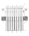
図1は、本実施形態に係る可動式防波施設の平面図である。図2は、図1のA−A矢視一部断面図である。この図2は、本実施形態に係る可動式防波堤が浮上した状態を示している。図3は、図1のB−B断面図である。この図3は、本実施形態に係る可動式防波堤が水底にある状態、すなわち浮上前の状態を示している。図4は、本実施形態に係る可動式防波堤を備える可動式防波施設の全体構成図である。図5〜図7は、本実施形態に係る可動式防波堤の浮上管が浮上する様子を示す模式図である。 FIG. 1 is a plan view of a movable wave-proof facility according to the present embodiment. 2 is a partial cross-sectional view taken along arrow AA in FIG. This FIG. 2 has shown the state which the movable breakwater which concerns on this embodiment surfaced. 3 is a cross-sectional view taken along line BB in FIG. FIG. 3 shows a state where the movable breakwater according to the present embodiment is at the bottom of the water, that is, a state before rising. FIG. 4 is an overall configuration diagram of a movable breakwater facility including a movable breakwater according to the present embodiment. 5-7 is a schematic diagram which shows a mode that the floating pipe of the movable breakwater which concerns on this embodiment floats.
図1〜図3に示すように、可動式防波施設1は、複数の可動式防波堤10と、監視・制御システム施設100とを含んで構成される。本実施形態において、複数の可動式防波堤10は、岸壁K1、K2の間に一列に配置されて、港の内側(港内BI)と港の外側(港外BO)とを仕切っている。可動式防波堤10は、外筒管11の内側に浮上管12が配置されるとともに、浮上管12の内部に気体(本実施形態では空気)を供給することによって浮上管12を浮上(上昇)させる構造である。なお、可動式防波堤10は、岸壁K1、K2の間に限らず、防波堤(固定式、杭式、浮体式を含む)での間にも設置可能である。また、可動式防波堤10は、岸壁K1、K2の間に限らず、複数配置されていてもよい。
As shown in FIGS. 1 to 3, the
それぞれの可動式防波堤10は、各送気管3から空気が送られる。複数の送気管3は、水底に配置される送気管ダクト2にまとめられて、一方の岸壁K2上の監視・制御システム施設100内に備えられる後述の気体供給装置に接続される。そして、有事の際、例えば、津波や高潮などの発生時には、気体供給装置から送気管3を介して、それぞれの可動式防波堤10の浮上管12内へ気体が供給されて、浮上管12が水底から浮上し、浮上管12の一部が水面から突出する。
Each
図2、図3に示すように、可動式防波堤10は、外筒管11(可動式防波堤10の固定部分)と、浮上管12(可動式防波堤10の可動部分)とを有する。外筒管11および浮上管12は、円筒形状の部材であり、鋼管で構成されている。外筒管11および浮上管12は、いずれも防食処理が施されている。なお、外筒管11および浮上管12は、円筒形状に限られるものではない。なお、外筒管11および浮上管12は、鋼管に限らず、例えば炭素繊維で構成されていてもよく、あるいは、外筒管11または浮上管12の一方が鋼管で、他方が炭素繊維で構成されるような異種材料による構造であってもよい。
As shown in FIGS. 2 and 3, the
外筒管11は、上端が開口して上下に長尺に形成され、水底地盤E内に打ち込まれている。外筒管11は、下層部が水底地盤E内に挿入固定され、上層部の周囲に捨石5が敷設されている。この捨石5の上面が水底面GLとなる。外筒管11は、水底側である上端に開口部11aを有する。また、外筒管11は、水底地盤Eに挿入された底部から上記送気管3が差し込まれて、内部に気体出口3aが配置される。
The
浮上管12は、外筒管11の内部に、外筒管11の開口部11aから、外筒管11の長手方向(管軸方向)に沿って差し込まれ、外筒管11の長手方向に対して昇降可能に配置されている。この浮上管12は、その内部に供給される気体によって浮力を発生して、外筒管11から浮上可能に構成される。具体的に、図3に示すように、浮上管12は、内部に複数の仕切部材(本実施形態では板状の部材)15,16が設けられている(以下、仕切部材15を第1仕切部材15といい、仕切部材16を第2仕切部材16という)。第1仕切部材15は、浮上管12の上方に配置され、第2仕切部材16は、第1仕切部材15の下方に配置される。また、浮上管12は、上端が蓋17によって閉塞されている。そして、浮上管12は、第1仕切部材15、第2仕切部材16、および蓋17によって、内部が複数の部屋に仕切られる。
The
第1仕切部材15と第2仕切部材16と浮上管12の側壁とで仕切られる空間13は、送気管3から浮上管12の内部に供給された気体を溜めて、浮上管12に浮力を発生させるための空間である。以下、空間13を気室13という。蓋17と第1仕切部材15と浮上管12の側壁とで仕切られる空間CRは、可動式防波堤10の状態を監視したり、送気管3から気体が供給されなかった場合に浮上管12を浮上させたり、浮上した浮上管12を下降させて外筒管11の内部に戻す動作をさせたりするための制御機器20が配置されている。以下、空間CRを機械室CRという。第2仕切部材16は、孔16aを備える。孔16aは、送気管3から浮上管12の内部に供給される気体を気室13へ導く。
The
浮上管12は、その側壁内面に浮力発生手段14が取り付けられる。浮力発生手段14は、例えば、気泡を有する樹脂、例えば、発泡スチロールなどである。また、浮力発生手段14は、単なる空間に空気や窒素などの気体を充填した構造としてもよい。可動式防波堤10は、有事の際には浮上管12の気室13に気体を供給し、この気体によって浮上管12に浮力を発生させ、浮上管12を外筒管11から浮上させる。浮力発生手段14を浮上管12に取り付けることにより、浮上管12を浮上させる際には、浮上管12を浮上させるために必要な浮力のうち、浮力発生手段14が発生する浮力で不足する分を気体によってまかなえばよい。これによって、浮上管12の内部に供給する気体の量を低減できるので、浮上管12を迅速に浮上させることができる。
Buoyancy generating means 14 is attached to the inner surface of the side wall of the
浮上管12は、その下端に開口部12aが設けられている。そして、開口部12aの下方に、送気管3の気体出口3aが配置される。なお、送気管3の気体入口は、上述した気体供給装置に接続されている。
The
気体供給装置は、図4に示すように、気体ボトル104と、気体ボトル104と送気管3との間に設けられる開閉弁110と、電動機103で駆動される圧縮機102とを含んで構成される。これらは、監視・制御システム施設100に備えられる。送気管3の気体入口は、気体供給装置を構成する開閉弁110に接続されている。気体ボトル104は、圧縮機102によって高圧(20MPa程度)の気体が充填される。そして、浮上管12を浮上させる際には、開閉弁110が開かれて、気体ボトル104内の気体が送気管3を通って浮上管12の内部に供給される。気体ボトル104は、それぞれの可動式防波堤10に対して設けられており、本実施形態では、1台の可動式防波堤10に対して2台の気体ボトル104が用意される。なお、それぞれの気体ボトル104に対して個別に送気管3を設け、2本の送気管3を浮上管12の開口部12aの下方に配置してもよい。
As shown in FIG. 4, the gas supply device includes a
1台の気体ボトル104によって、1台の可動式防波堤10の浮上管12を浮上させることができるが、1台の可動式防波堤10に対して2台の気体ボトル104を用意することで、一方の気体供給系統に何らかの不具合が発生した場合には、もう一方をバックアップとして用いることにより、より確実に浮上管12を浮上させることができる。また、2台の気体ボトル104から1台の可動式防波堤10へ気体を供給することにより、気体ボトル104を単独で用いるよりも迅速に浮上管12を浮上させることができる。なお、1台の気体ボトル104によって、3台の可動式防波堤10の浮上管12を浮上させるように構成する例として、中央の可動式防波堤10の浮上管12にのみ送気管3で送気し、その両側の可動式防波堤10では、中央の可動式防波堤10よりも浮力発生手段14の体積を大きくしてほぼ中性浮力とし、両側の可動式防波堤10の浮上管12を、中央の浮上管12によって吊り上げるように浮上させる構成にすることが好ましい。このように構成することで、送気管3の数を減少させることが可能になる。また、同様の構成により、1台の気体ボトル104によって、5台の可動式防波堤10の浮上管12を浮上させるように構成することも可能である。このように、1台の気体ボトル104で複数の可動式防波堤10の浮上管12を浮上させるように構成してもよい。
The floating
電動機103および圧縮機102は、監視・制御装置101によって制御される。監視・制御装置101は、例えば、気体ボトル104内に充填されている気体の圧力を気体圧力センサ111によって取得し、規定の圧力よりも低い場合には電動機103を駆動して圧縮機102を作動させ、規定の圧力になるまで圧縮機102から気体ボトル104内へ気体を充填する。また、監視・制御装置101は、送気管3に設けられた送気管3内の圧力を検出する送気管圧力検出センサ(送気管内圧力検出手段)105から送気管3内の圧力を取得して、送気管3に漏洩箇所があるか否かを監視する。
The
さらに、監視・制御装置101は、可動式防波堤10の機械室CR内の制御機器20と通信して、可動式防波堤10の状態を監視したり、浮上管12の動きを制御したりする。例えば、浮上した浮上管12を外筒管11内に戻す場合、監視・制御装置101は、制御機器20を介して、気室13と気室13の外部とを接続する送気管の途中に設けられた排気弁18を開く。これによって、気室13内の気体が気室13の外部に放出されるとともに、気室13内の気体が水に置換されて浮上管12の浮力が低下するので、浮上管12は沈降して外筒管11内に収まる。
Further, the monitoring /
有事の際、例えば、監視・制御装置101が津波や高潮などの警報を受信した場合、監視・制御装置101は、開閉弁110を開き、図5に示すように、送気管3を介して気体ボトル104内の気体を浮上管12の内部に供給する。送気管3から浮上管12内へ供給された気体は、図5に示すように、第2仕切部材16の孔16aを通って気室13へ入る。気室13の内部の気体によって発生する浮力と、浮力発生手段14によって発生する浮力との和が水中における浮上管12全体の重量を超えると、図6に示すように、浮上管12は、水面WLに向かって外筒管11から浮上を開始する。そして、図7に示すように、浮上管12の一部が水面WL上に突出する。このとき、気室13内の余分な気体は、気室13に設けられた孔D1から排出される。また、機械室CR内の水は、機械室CRに設けられた孔D2から排水される。このようにして、有事の際には、図2に示すように複数の浮上管12が一列に水面WLから突出して防波堤の機能を発揮し、津波や高潮などから港湾設備などを保護する。
In the event of an emergency, for example, when the monitoring /
図8は、図1のB−B拡大断面図である。この図8は、本実施形態に係る可動式防波堤が水底にある状態、すなわち浮上前の状態を示している。図9は、図8のC−C矢視図である。可動式防波堤10は、浮上管12に充電装置および蓄電池が内蔵されている。充電装置および蓄電池は、図には明示しないが、上述した制御機器20に設けられている。また、図8および図9に示すように、可動式防波堤10は、電力受信部21および電力送信部22を有している。
8 is an enlarged cross-sectional view taken along the line BB in FIG. FIG. 8 shows a state where the movable breakwater according to the present embodiment is at the bottom of the water, that is, a state before rising. FIG. 9 is a view taken along the line CC in FIG. In the
電力受信部21は、浮上管12に設けられており、蓄電池に電力を供給したり、水中通信における送受信をしたりするためのものである。また、電力送信部22は、浮上管12の下降時において電力受信部21に電力を送信したり、水中通信における送受信をしたりするためのものである。これら、電力受信部21および電力送信部22は、互いに対向することで、電磁誘導を利用して電力や通信信号を非接触(例えば0mmを超え30mm程度の隙間を隔て)で伝送する。
The
電力送信部22は、陸上の監視・制御システム施設100が備える電源(図示せず)と電気的に接続されている。電源は、交流をそのまま、あるいは直流電源をインバータによって交流に変換して、電力送信部22へ送る。電力送信部22は、給電側コイルと給電回路とからなり、電力受信部21は、受電側コイルと受電回路とからなる。すなわち、電力送信部22の給電側コイルへ交流が流れることにより発生する磁界の変化によって、電力受信部21の受電側コイルへ誘導起電力を発生させ、非接触で電源から送られる電力を制御機器20の充電装置へ伝送する。このように、電力送信部22で電気エネルギを磁気エネルギに変換して伝送し、電力受信部21でその磁気エネルギを電気エネルギに変換して、非接触で電力を伝送する。なお、充電装置は、電力受信部21から交流で伝送されてきた電力を直流に変換し、蓄電池へ充電するものである。
The
電力送信部22は、外筒管11において、水底面GLから所定深さH1で捨石5により埋設された範囲で、外筒管11の側壁が切り欠かれた箇所に設けられている。具体的に、電力送信部22は、外筒管11の側壁が切り欠かれた箇所で、リブなどで補強されたブラケット22aを介して外筒管11に固定されている。このため、電力送信部22は、水底面GLよりも下方に配置されることになる。
The
電力受信部21は、浮上管12の下降位置(下降により浮上管12の上端が水底面GLと一致する位置)において、浮上管12の上端よりも下方の範囲で浮上管12の側壁が切り欠かれた箇所にて電力送信部22に対向して設けられている。具体的に、電力受信部21は、浮上管12の側壁が切り欠かれた箇所で、リブなどで補強されたブラケット21aを介して浮上管12に固定されている。このため、電力受信部21は、水底面GLよりも下方に配置されることになる。また、電力受信部21は、浮上管12の上端に設けられた蓋17により上方が覆われている。
The
また、図9において符号23で示す部分は、浮上管12の外壁に長手(水深)方向に沿って設けられ、浮上管12が外筒管11に対して回転する事態を防止する回転防止部材である。かかる回転防止部材23により、電力受信部21と電力送信部22とは、互いに対向する位置が決められることになる。
9 is a rotation prevention member that is provided on the outer wall of the
以下、上述した可動式防波施設1に設けられる可動式防波堤10の要部詳細について図を参照して説明する。図10は、本実施形態に係る可動式防波堤の拡大縦断面図であり、図11は、本実施形態に係る可動式防波堤の拡大平面図である。これら図10および図11は、本実施形態に係る可動式防波堤が水底にある状態、すなわち浮上前の状態を示している。図12は、本実施形態に係る可動式防波堤における送気管の拡大断面図である。
Hereinafter, the detail of the principal part of the
図10および図11に示すように、送気管3は、水底地盤Eに挿入された外筒管11の底部から先端部3Aが差し込まれて、内部に気体出口3aが配置される。このように送気管3が配置される外筒管11は、その外側に、上端から上下方向に連続して上部11Aaが開口し底部11Abが閉塞された空間を形成するガイド部11Aを有している。ガイド部11Aは、図11において三角形状の空間を形成するように示されているが、空間の形状に限定はない。また、ガイド部11Aは、その底部11Abが、外筒管11の外周面に近づくにつれて下方に傾斜して閉塞されている。また、外筒管11は、ガイド部11Aの閉塞された底部11Abでガイド部11Aの空間から自身の内部に通じる開口穴11Bを有している。開口穴11Bは、ガイド部11Aの底部11Abが外筒管11の外周面に当接する位置の直上に設けられており、かつ浮上管12が浮上される前の状態で、下端の開口部12aよりも下方となる位置に設けられている。
As shown in FIGS. 10 and 11, in the
図12に示すように、送気管3は、送気本体部3Bの先端に先端部3Aが設けられている。送気本体部3Bは、耐薬品性、耐水性、耐熱性に優れ、かつ可撓性を有するようにフッ素樹脂により形成されたもので、内管3Baと外管3Bbとで二重構造とされている。先端部3Aは、耐薬品性、耐食性、耐熱性に優れるステンレス合金により形成されている。先端部3Aは、外筒管11の開口穴11Bに挿入可能な外形に形成され、先端に向かって外形が細くなるテーパ面を有している。先端部3Aは、送気本体部3Bの内管3Baおよび外管3Bbが連結され、内管3Baに連通して貫通する貫通穴3Aaを有するとともに、外管3Bbを閉塞するように外管3Bbに結合される結合部3Abを有する。先端部3Aは、貫通穴3Aaの先端の開口部が気体出口3aとなる。
As shown in FIG. 12, the
また、先端部3Aは、外筒管11の開口穴11Bに係止される係止部3Cを有している。係止部3Cは、係止爪3Caと、弾性部材3Cbと、解除手段3Ccとを有している。係止爪3Caは、先端部3Aの外周面に形成された凹部3Ac内に配置され、先端部3Aの先端側に向く先端部に設けられた揺動軸3Caaにより、凹部3Acの外部に基端部が突出する形態と、凹部3Acの内部に全体が収納される形態とに揺動可能に設けられている。係止爪3Caは、凹部3Acの外部に基端部が突出する形態で先端部3Aの外周面よりも外側に突出し、凹部3Acの内部に全体が収納される形態で先端部3Aの外周面よりも内側に没入する。係止爪3Caは、先端部3Aと同様に耐薬品性、耐食性、耐熱性に優れるステンレス合金により形成されてもよく、合成樹脂材で形成されていてもよい。この係止爪3Caは、先端部3Aの外周面よりも外側に突出することで、外筒管11の内部で開口穴11Bの縁部に係止し、開口穴11Bに挿入された先端部3Aが、外筒管11の内部からガイド部11A側に抜けないように抜け止めする。一方、係止爪3Caは、先端部3Aの外周面よりも内側に没入することで、先端部3Aの開口穴11Bに対する挿通を許容する。
Further, the
弾性部材3Cbは、係止爪3Caを先端部3Aの外周面よりも外側に突出するように付勢するもので、バネ材からなる。バネ材としては、例えば、圧縮コイルバネや板バネがあり、先端部3Aおよび係止爪3Caと同様に耐薬品性、耐食性、耐熱性に優れるステンレス合金により形成されてもよく、係止爪3Caと同様に合成樹脂材で形成されていてもよい。すなわち、弾性部材3Cbは、係止爪3Caを先端部3Aの外周面よりも外側に突出するように付勢することで、係止爪3Caが外筒管11の開口穴11Bの縁部に係止して、先端部3Aを開口穴11Bから抜け止めする形態を維持する。なお、係止爪3Caは、先端部3Aの先端側に向く先端部に設けられた揺動軸3Caaにより揺動可能に設けられている。このため、ガイド部11A側から外筒管11の内部に配置するように先端部3Aを開口穴11Bに挿入する場合は、開口穴11Bの内周面により弾性部材3Cbの付勢力に抗して係止爪3Caが凹部3Acの内部に全体が収納される形態となり、先端部3Aの外周面よりも内側に没入するため、先端部3Aが開口穴11Bに挿入されることを係止爪3Caが阻害することはない。
The elastic member 3Cb urges the locking claw 3Ca to protrude outward from the outer peripheral surface of the
解除手段3Ccは、弾性部材3Cbの付勢力に抗して係止爪3Caを先端部3Aの外周面よりも内側に没入移動させるもので、本実施形態では、係止爪3Caの基端側に連結されたワイヤやロープなどの索状部材として構成されている。索状部材としての解除手段3Ccは、先端部3Aの基端側から送気本体部3Bの内管3Baと外管3Bbとの間に配置され、送気本体部3Bの基端に至り延長されている。すなわち、索状部材としての解除手段3Ccを送気本体部3Bの基端に向けて引っ張ることで、係止爪3Caが凹部3Acの内部に全体が収納される形態となり、先端部3Aの外周面よりも内側に没入するため、係止爪3Caの係止が解除され、先端部3Aの開口穴11Bに対する挿通が許容されることになる。この解除手段3Ccは、図12に示すように先端部3Aの複数箇所に設けられていてもよく、単一箇所に設けられていてもよい。複数箇所に設けられる場合、複数の索状部材を内管3Baと外管3Bbとの間で1つにまとめてもよい。
The release means 3Cc moves the locking claw 3Ca into the inner side of the outer peripheral surface of the
なお、送気管3は、送気本体部3Bの基端に、接続フランジ3Dが設けられている。接続フランジ3Dは、送気管3を途中で分割した場合に、送気管3の相互を接続するためのものである。送気管3を途中で分割するのは、例えば、図10に示すように、ガイド部11Aの内部や、湾曲が必要な箇所を可撓性を有する送気管3とし、水底面GLに沿う箇所、水底面GLから上方に延在する直線状の箇所を硬質の送気管3とするためである。
The
図13および図14は、本実施形態に係る可動式防波堤における送気管の取り付け手順を示す拡大縦断面図である。なお、図13および図14は、外筒管11が水底地盤E内に打ち込まれた後であり、浮上管12を設置する前の状態を示す。
FIG. 13 and FIG. 14 are enlarged longitudinal sectional views showing a procedure for attaching the air pipe in the movable breakwater according to the present embodiment. 13 and 14 show a state after the
図13に示すように、送気管3は、ガイド部11Aにおける上部11Aaの開口から先端部3Aがガイド部11Aの内部に挿入され、下方に押し込まれていく。送気管3の先端部3Aは、徐々にガイド部11Aの内部を下方に移動する。この際、係止部3Cは、ガイド部11Aの内面に接触することで、凹部3Ac側に押されるため、先端部3Aの移動を妨げない。万一、係止部3Cが先端部3Aの移動を妨げるような場合、解除手段3Ccにより、係止爪3Caが凹部3Acの内部に全体が収納されるように、弾性部材3Cbの付勢力に抗して係止爪3Caを先端部3Aの外周面よりも内側に没入移動させればよい。そして、先端部3Aがガイド部11Aの底部11Abに到達すると、先端部3Aは、底部11Abの傾斜に案内され、図14に示すように開口穴11Bに挿入される。先端部3Aが開口穴11Bに挿入されると、係止部3Cが外筒管11の内部で開口穴11Bの縁部に係止し、開口穴11Bに挿入された先端部3Aを抜け止めする。その後、接続フランジ3Dにより分割された送気管3同士を連結する。また、送気管3を交換する場合、解除手段3Ccにより、係止爪3Caが凹部3Acの内部に全体が収納されるように、弾性部材3Cbの付勢力に抗して係止爪3Caを先端部3Aの外周面よりも内側に没入移動させれば、先端部3Aの開口穴11Bに対する挿通が許容され、先端部3Aを開口穴11Bから抜くことが可能になる。
As shown in FIG. 13, in the
このように、本実施形態の可動式防波堤10は、上下に長尺に形成され、水底側に開口部11aを有して水底地盤E内に挿入固定された外筒管11と、外筒管11の内部に挿入され、外筒管11の長手方向に昇降移動可能に配置されるとともに、自身の内部に供給された気体により浮力を生じて上昇可能に設けられた浮上管12と、浮上管12の内部に気体を供給する送気管3とを備える可動式防波堤10である。そして、この可動式防波堤10において、外筒管11は、その外側に上端から上下方向に連続して上部11Aaが開口し底部11Abが閉塞された空間を形成するガイド部11Aと、ガイド部11Aの閉塞された底部11Abの位置でガイド部11Aの空間から自身の内部に通じる開口穴11Bとを有しており、送気管3は、ガイド部11Aの上部11Aaの開口から挿入されて先端部3Aが底部11Abに至り開口穴11Bに挿入され、当該先端部3Aに開口穴11Bの縁部に係止される係止部3Cを有する。
As described above, the
この可動式防波堤10によれば、ガイド部11Aにより、水底地盤E内に挿入固定された外筒管11の外側に沿って送気管3の先端部3Aを開口穴11Bに挿入される位置まで移動させることができる。しかも、係止部3Cにより、開口穴11Bに挿入された先端部3Aを係止し、開口穴11Bから先端部3Aを抜け止めすることができる。この結果、送気管3の配置状態を維持することができる。
According to this
また、本実施形態の可動式防波堤10では、送気管3は、開口穴11Bに対する係止部3Cの係止を解除する解除手段3Ccを有することが好ましい。
Moreover, in the
この可動式防波堤10によれば、解除手段3Ccにより開口穴11Bに対する係止部3Cの係止を解除することで、送気管3の交換時などの際に、送気管3の先端部3Aを開口穴11Bから容易に抜くことができる。
According to this
ところで、図15は、本実施形態に係る可動式防波堤における送気管の固定構造の他の例を示す拡大縦断面図である。 Incidentally, FIG. 15 is an enlarged longitudinal sectional view showing another example of the fixing structure of the air pipe in the movable breakwater according to this embodiment.
図15に示す可動式防波堤10では、送気管3の先端部3Aに、上述した係止部3Cを設けていないが、ガイド部11Aの内部であって送気管3が開口穴11Bに挿入される部分に注入されて送気管3の移動を規制する充填部材30を有する。充填部材30は、例えば、発泡ウレタンからなる。そして、送気管3の先端部3Aが開口穴11Bに挿入された状態で、ガイド部11Aの上部11Aaの開口から底部11Abに向けて注入管(図示せず)を挿通し、送気管3が開口穴11Bに挿入される部分に充填部材30を注入する。
In the
このように、図15に示す本実施形態の可動式防波堤10は、上下に長尺に形成され、水底側に開口部11aを有して水底地盤E内に挿入固定された外筒管11と、外筒管11の内部に挿入され、外筒管11の長手方向に昇降移動可能に配置されるとともに、自身の内部に供給された気体により浮力を生じて上昇可能に設けられた浮上管12と、浮上管12の内部に気体を供給する送気管3とを備える可動式防波堤10である。そして、この可動式防波堤10において、外筒管11は、その外側に上端から上下方向に連続して上部11Aaが開口し底部11Abが閉塞された空間を形成するガイド部11Aと、ガイド部11Aの閉塞された底部11Abの位置でガイド部11Aの空間から自身の内部に通じる開口穴11Bとを有しており、送気管3は、ガイド部11Aの上部11Aaの開口から挿入されて先端部3Aが底部11Abに至り開口穴11Bに挿入されている。そして、ガイド部11Aの内部であって送気管3が開口穴11Bに挿入される部分に注入されて送気管3の移動を規制する充填部材30を有する。
As described above, the
この可動式防波堤10によれば、ガイド部11Aにより、水底地盤E内に挿入固定された外筒管11の外側に沿って送気管3の先端部3Aを開口穴11Bに挿入される位置まで移動させることができる。しかも、充填部材30により、開口穴11Bに挿入された送気管3の移動を規制することで、開口穴11Bから先端部3Aを抜け止めすることができる。この結果、送気管3の配置状態を維持することができる。
According to this
また、図16は、本実施形態に係る可動式防波堤における送気管の固定構造の追加例を示す拡大縦断面図である。 FIG. 16 is an enlarged vertical cross-sectional view showing an additional example of an air pipe fixing structure in the movable breakwater according to the present embodiment.
図16に示す可動式防波堤10は、上述した係止部3Cや充填部材30を有したうえで、送気管3を外筒管11側に固定する固定部31を有する。固定部31は、ガイド部11Aの上部11Aaの開口の位置に設置される。固定部31は、ガイド部11Aの側部において外筒管11に固定された固定板31Aと、この固定板31Aにナット31Baにより固定されて送気管3の周りを抑えるU字形状のU形ボルト31Bとを有する。この固定部31は、単一で配置されていてもよいが、本実施形態では、図16に示すように、ガイド部11Aの両側部に固定板31Aを固定し、2つのU形ボルト31Bで送気管3を両側から囲むように構成している。
The
このように、図16に示す可動式防波堤10では、ガイド部11Aの上部11Aaの開口の位置で送気管3を外筒管11側に固定する固定部31を有することが好ましい。
As described above, the
この可動式防波堤10によれば、係止部3Cや充填部材30により開口穴11Bから先端部3Aを抜け止めしたうえで、さらに固定部31により、ガイド部11Aの上部11Aaの開口の位置で送気管3を外筒管11側に固定したことにより、送気管3の配置状態を維持する効果をより顕著に得ることができる。
According to this
また、上述した可動式防波堤10を水底に複数配列した可動式防波施設1によれば、送気管3の配置状態が維持されることで、可動式防波堤10の可動を支障なく行うことができる。
Moreover, according to the
1 可動式防波施設
3 送気管
3a 気体出口
3A 先端部
3Aa 貫通穴
3Ab 結合部
3Ac 凹部
3B 送気本体部
3Ba 内管
3Bb 外管
3C 係止部
3Ca 係止爪
3Caa 揺動軸
3Cb 弾性部材
3Cc 解除手段
3D 接続フランジ
10 可動式防波堤
11 外筒管
11a 開口部
11A ガイド部
11Aa 上部
11Ab 底部
11B 開口穴
12 浮上管
12a 開口部
30 充填部材
31 固定部
31A 固定板
31B U形ボルト
31Ba ナット
DESCRIPTION OF
Claims (5)
前記外筒管は、その外側に上端から上下方向に連続して上部が開口し底部が閉塞された空間を形成するガイド部と、前記ガイド部の閉塞された底部の位置で前記ガイド部の空間から自身の内部に通じる開口穴とを有しており、
前記送気管は、前記ガイド部の上部の開口から挿入されて先端部が前記底部に至り前記開口穴に挿入され、当該先端部に前記開口穴の縁部に係止される係止部を有することを特徴とする可動式防波堤。 An outer cylindrical tube that is formed vertically and has an opening on the bottom of the water and is inserted and fixed in the bottom of the water bottom, and is inserted into the outer cylindrical tube and moved up and down in the longitudinal direction of the outer cylindrical tube In a movable breakwater provided with a levitation tube that is arranged so as to be able to rise by generating buoyancy by the gas supplied to itself and an air supply tube that supplies gas to the inside of the levitation tube,
The outer tube has a guide portion that forms a space in which an upper portion is continuously opened from the upper end in the vertical direction on the outer side and a bottom portion is closed, and a space of the guide portion at the closed bottom portion of the guide portion. And has an opening hole that leads to the inside of the
The air supply pipe has an engaging portion that is inserted from the opening at the top of the guide portion, the distal end portion reaches the bottom portion, is inserted into the opening hole, and is engaged with the edge portion of the opening hole at the distal end portion. This is a movable breakwater.
前記外筒管は、その外側に上端から上下方向に連続して上部が開口し底部が閉塞された空間を形成するガイド部と前記ガイド部の閉塞された底部の位置で前記ガイド部の空間から自身の内部に通じる開口穴とを有し、前記送気管は、前記ガイド部の上部の開口から挿入されて先端部が前記底部に至り前記開口穴に挿入されており、
前記ガイド部の内部であって前記送気管が前記開口部に挿入される部分に注入されて前記送気管の移動を規制する充填部材を有することを特徴とする可動式防波堤。 An outer cylindrical tube that is formed vertically and has an opening on the bottom of the water and is inserted and fixed in the bottom of the water bottom, and is inserted into the outer cylindrical tube and moved up and down in the longitudinal direction of the outer cylindrical tube In a movable breakwater provided with a levitation tube that is arranged so as to be able to rise by generating buoyancy by the gas supplied to itself and an air supply tube that supplies gas to the inside of the levitation tube,
The outer cylindrical tube is formed from the space of the guide portion at the position of the guide portion that forms a space in which the upper portion continuously opens from the upper end to the outside in the vertical direction and the bottom portion is closed, and the closed bottom portion of the guide portion. An opening hole that communicates with itself, and the air supply pipe is inserted from the opening at the top of the guide part, and the tip part reaches the bottom part and is inserted into the opening hole,
A movable breakwater characterized by having a filling member that is injected into a portion of the guide portion where the air supply pipe is inserted into the opening to restrict movement of the air supply pipe.
Priority Applications (1)
| Application Number | Priority Date | Filing Date | Title |
|---|---|---|---|
| JP2014047924A JP6296603B2 (en) | 2014-03-11 | 2014-03-11 | Movable breakwater and movable breakwater facility |
Applications Claiming Priority (1)
| Application Number | Priority Date | Filing Date | Title |
|---|---|---|---|
| JP2014047924A JP6296603B2 (en) | 2014-03-11 | 2014-03-11 | Movable breakwater and movable breakwater facility |
Publications (2)
| Publication Number | Publication Date |
|---|---|
| JP2015172283A JP2015172283A (en) | 2015-10-01 |
| JP6296603B2 true JP6296603B2 (en) | 2018-03-20 |
Family
ID=54259749
Family Applications (1)
| Application Number | Title | Priority Date | Filing Date |
|---|---|---|---|
| JP2014047924A Active JP6296603B2 (en) | 2014-03-11 | 2014-03-11 | Movable breakwater and movable breakwater facility |
Country Status (1)
| Country | Link |
|---|---|
| JP (1) | JP6296603B2 (en) |
Family Cites Families (4)
| Publication number | Priority date | Publication date | Assignee | Title |
|---|---|---|---|---|
| JP2008133602A (en) * | 2006-11-27 | 2008-06-12 | Shimizu Corp | Elevating wave protection structure |
| JP5614743B2 (en) * | 2010-10-29 | 2014-10-29 | 独立行政法人港湾空港技術研究所 | Port entrance blocking structure |
| JP5269868B2 (en) * | 2010-12-10 | 2013-08-21 | 三菱重工鉄構エンジニアリング株式会社 | Movable breakwater and movable breakwater facility |
| GB201310299D0 (en) * | 2013-06-10 | 2013-07-24 | Lee Christopher E | Storm inflatable dam deployment system |
-
2014
- 2014-03-11 JP JP2014047924A patent/JP6296603B2/en active Active
Also Published As
| Publication number | Publication date |
|---|---|
| JP2015172283A (en) | 2015-10-01 |
Similar Documents
| Publication | Publication Date | Title |
|---|---|---|
| KR102134109B1 (en) | Mooring buoys for floating wind turbines | |
| EP2569564B1 (en) | Cable pull-in system and method for offshore structures | |
| JP6131569B2 (en) | Offshore wind power generation wiring system and offshore wind power generation system | |
| JP5269868B2 (en) | Movable breakwater and movable breakwater facility | |
| JP2017537246A (en) | Submarine terminal for maritime activities | |
| KR101017475B1 (en) | Algae generator with subsea swivel | |
| JP6296603B2 (en) | Movable breakwater and movable breakwater facility | |
| JP6121252B2 (en) | Movable breakwater | |
| JP5647562B2 (en) | External power supply and freshwater receiving facility, power supply and freshwater supply ship, and power supply and freshwater supply system comprising them | |
| JP6218304B2 (en) | Movable breakwater and movable breakwater facility | |
| JP5303312B2 (en) | Movable breakwater and movable breakwater facility | |
| JP5361052B2 (en) | Movable breakwater and operating method of movable breakwater | |
| JP5303313B2 (en) | Movable breakwater, movable breakwater facility, and method for estimating gas leak location of movable breakwater | |
| JP5378007B2 (en) | Movable breakwater and movable breakwater facility | |
| JP2015172282A (en) | movable breakwater facility | |
| JP6369833B2 (en) | Movable breakwater and movable breakwater facility | |
| KR101016456B1 (en) | Algae Generator | |
| JP2012097419A (en) | Harbor entrance blocking structure | |
| EP2320068A1 (en) | Device for converting wave energy into electrical energy | |
| JP2013141909A (en) | Self-sinking device for float protection | |
| JP2003171955A (en) | Small diameter pipe large capacity oceanic surface layer water or deep layer water intake system using submerged motor pump, land installation type oceanic surface layer water or deep layer water intake facility using submerged pump, maintenance method and its construction method | |
| JP2014147240A (en) | Float-equipped power generator | |
| JP5526056B2 (en) | Mobile wave breaker and breakwater blockage structure | |
| JP2015175127A (en) | movable breakwater and movable breakwater facility | |
| WO2022157485A1 (en) | Subsea monitoring apparatus |
Legal Events
| Date | Code | Title | Description |
|---|---|---|---|
| A711 | Notification of change in applicant |
Free format text: JAPANESE INTERMEDIATE CODE: A712 Effective date: 20161101 |
|
| A521 | Request for written amendment filed |
Free format text: JAPANESE INTERMEDIATE CODE: A523 Effective date: 20170123 |
|
| A621 | Written request for application examination |
Free format text: JAPANESE INTERMEDIATE CODE: A621 Effective date: 20170310 |
|
| RD02 | Notification of acceptance of power of attorney |
Free format text: JAPANESE INTERMEDIATE CODE: A7422 Effective date: 20170310 |
|
| A521 | Request for written amendment filed |
Free format text: JAPANESE INTERMEDIATE CODE: A821 Effective date: 20170310 |
|
| A977 | Report on retrieval |
Free format text: JAPANESE INTERMEDIATE CODE: A971007 Effective date: 20180117 |
|
| TRDD | Decision of grant or rejection written | ||
| A01 | Written decision to grant a patent or to grant a registration (utility model) |
Free format text: JAPANESE INTERMEDIATE CODE: A01 Effective date: 20180123 |
|
| A61 | First payment of annual fees (during grant procedure) |
Free format text: JAPANESE INTERMEDIATE CODE: A61 Effective date: 20180216 |
|
| R150 | Certificate of patent or registration of utility model |
Ref document number: 6296603 Country of ref document: JP Free format text: JAPANESE INTERMEDIATE CODE: R150 |
|
| S533 | Written request for registration of change of name |
Free format text: JAPANESE INTERMEDIATE CODE: R313533 |
|
| R350 | Written notification of registration of transfer |
Free format text: JAPANESE INTERMEDIATE CODE: R350 |
|
| R250 | Receipt of annual fees |
Free format text: JAPANESE INTERMEDIATE CODE: R250 |
|
| R250 | Receipt of annual fees |
Free format text: JAPANESE INTERMEDIATE CODE: R250 |
|
| R250 | Receipt of annual fees |
Free format text: JAPANESE INTERMEDIATE CODE: R250 |
|
| R250 | Receipt of annual fees |
Free format text: JAPANESE INTERMEDIATE CODE: R250 |