JP6258128B2 - Trigger type liquid ejector - Google Patents
Trigger type liquid ejector Download PDFInfo
- Publication number
- JP6258128B2 JP6258128B2 JP2014113469A JP2014113469A JP6258128B2 JP 6258128 B2 JP6258128 B2 JP 6258128B2 JP 2014113469 A JP2014113469 A JP 2014113469A JP 2014113469 A JP2014113469 A JP 2014113469A JP 6258128 B2 JP6258128 B2 JP 6258128B2
- Authority
- JP
- Japan
- Prior art keywords
- flow path
- pump
- liquid
- check valve
- flow
- Prior art date
- Legal status (The legal status is an assumption and is not a legal conclusion. Google has not performed a legal analysis and makes no representation as to the accuracy of the status listed.)
- Expired - Fee Related
Links
- 239000007788 liquid Substances 0.000 title claims description 111
- 230000002093 peripheral effect Effects 0.000 claims description 66
- 238000011144 upstream manufacturing Methods 0.000 claims description 9
- 230000004048 modification Effects 0.000 description 4
- 238000012986 modification Methods 0.000 description 4
- 239000003795 chemical substances by application Substances 0.000 description 3
- 239000006260 foam Substances 0.000 description 3
- 239000003595 mist Substances 0.000 description 3
- 230000036544 posture Effects 0.000 description 3
- 239000003599 detergent Substances 0.000 description 2
- 239000003205 fragrance Substances 0.000 description 2
- 239000011347 resin Substances 0.000 description 2
- 229920005989 resin Polymers 0.000 description 2
- 239000001993 wax Substances 0.000 description 2
- 239000003905 agrochemical Substances 0.000 description 1
- 238000007599 discharging Methods 0.000 description 1
- 238000002347 injection Methods 0.000 description 1
- 239000007924 injection Substances 0.000 description 1
- 239000000463 material Substances 0.000 description 1
- -1 mold removers Substances 0.000 description 1
- 230000001105 regulatory effect Effects 0.000 description 1
- 239000005871 repellent Substances 0.000 description 1
- 230000002940 repellent Effects 0.000 description 1
- 239000000126 substance Substances 0.000 description 1
- 230000001960 triggered effect Effects 0.000 description 1
Images


Classifications
-
- B—PERFORMING OPERATIONS; TRANSPORTING
- B05—SPRAYING OR ATOMISING IN GENERAL; APPLYING FLUENT MATERIALS TO SURFACES, IN GENERAL
- B05B—SPRAYING APPARATUS; ATOMISING APPARATUS; NOZZLES
- B05B11/00—Single-unit hand-held apparatus in which flow of contents is produced by the muscular force of the operator at the moment of use
- B05B11/01—Single-unit hand-held apparatus in which flow of contents is produced by the muscular force of the operator at the moment of use characterised by the means producing the flow
- B05B11/10—Pump arrangements for transferring the contents from the container to a pump chamber by a sucking effect and forcing the contents out through the dispensing nozzle
- B05B11/1042—Components or details
-
- B—PERFORMING OPERATIONS; TRANSPORTING
- B05—SPRAYING OR ATOMISING IN GENERAL; APPLYING FLUENT MATERIALS TO SURFACES, IN GENERAL
- B05B—SPRAYING APPARATUS; ATOMISING APPARATUS; NOZZLES
- B05B11/00—Single-unit hand-held apparatus in which flow of contents is produced by the muscular force of the operator at the moment of use
- B05B11/0005—Components or details
- B05B11/0059—Components or details allowing operation in any orientation, e.g. for discharge in inverted position
-
- B—PERFORMING OPERATIONS; TRANSPORTING
- B05—SPRAYING OR ATOMISING IN GENERAL; APPLYING FLUENT MATERIALS TO SURFACES, IN GENERAL
- B05B—SPRAYING APPARATUS; ATOMISING APPARATUS; NOZZLES
- B05B11/00—Single-unit hand-held apparatus in which flow of contents is produced by the muscular force of the operator at the moment of use
- B05B11/01—Single-unit hand-held apparatus in which flow of contents is produced by the muscular force of the operator at the moment of use characterised by the means producing the flow
- B05B11/10—Pump arrangements for transferring the contents from the container to a pump chamber by a sucking effect and forcing the contents out through the dispensing nozzle
- B05B11/1001—Piston pumps
- B05B11/1009—Piston pumps actuated by a lever
- B05B11/1011—Piston pumps actuated by a lever without substantial movement of the nozzle in the direction of the pressure stroke
-
- B—PERFORMING OPERATIONS; TRANSPORTING
- B05—SPRAYING OR ATOMISING IN GENERAL; APPLYING FLUENT MATERIALS TO SURFACES, IN GENERAL
- B05B—SPRAYING APPARATUS; ATOMISING APPARATUS; NOZZLES
- B05B11/00—Single-unit hand-held apparatus in which flow of contents is produced by the muscular force of the operator at the moment of use
- B05B11/01—Single-unit hand-held apparatus in which flow of contents is produced by the muscular force of the operator at the moment of use characterised by the means producing the flow
- B05B11/10—Pump arrangements for transferring the contents from the container to a pump chamber by a sucking effect and forcing the contents out through the dispensing nozzle
- B05B11/1001—Piston pumps
- B05B11/1023—Piston pumps having an outlet valve opened by deformation or displacement of the piston relative to its actuating stem
- B05B11/1025—Piston pumps having an outlet valve opened by deformation or displacement of the piston relative to its actuating stem a spring urging the outlet valve in its closed position
-
- B—PERFORMING OPERATIONS; TRANSPORTING
- B05—SPRAYING OR ATOMISING IN GENERAL; APPLYING FLUENT MATERIALS TO SURFACES, IN GENERAL
- B05B—SPRAYING APPARATUS; ATOMISING APPARATUS; NOZZLES
- B05B11/00—Single-unit hand-held apparatus in which flow of contents is produced by the muscular force of the operator at the moment of use
- B05B11/01—Single-unit hand-held apparatus in which flow of contents is produced by the muscular force of the operator at the moment of use characterised by the means producing the flow
- B05B11/10—Pump arrangements for transferring the contents from the container to a pump chamber by a sucking effect and forcing the contents out through the dispensing nozzle
- B05B11/1038—Pressure accumulation pumps, i.e. pumps comprising a pressure accumulation chamber
- B05B11/1039—Pressure accumulation pumps, i.e. pumps comprising a pressure accumulation chamber the outlet valve being mechanically opened after a defined accumulation stroke
-
- B—PERFORMING OPERATIONS; TRANSPORTING
- B05—SPRAYING OR ATOMISING IN GENERAL; APPLYING FLUENT MATERIALS TO SURFACES, IN GENERAL
- B05B—SPRAYING APPARATUS; ATOMISING APPARATUS; NOZZLES
- B05B11/00—Single-unit hand-held apparatus in which flow of contents is produced by the muscular force of the operator at the moment of use
- B05B11/01—Single-unit hand-held apparatus in which flow of contents is produced by the muscular force of the operator at the moment of use characterised by the means producing the flow
- B05B11/10—Pump arrangements for transferring the contents from the container to a pump chamber by a sucking effect and forcing the contents out through the dispensing nozzle
- B05B11/1042—Components or details
- B05B11/1043—Sealing or attachment arrangements between pump and container
- B05B11/1045—Sealing or attachment arrangements between pump and container the pump being preassembled as an independent unit before being mounted on the container
-
- B—PERFORMING OPERATIONS; TRANSPORTING
- B05—SPRAYING OR ATOMISING IN GENERAL; APPLYING FLUENT MATERIALS TO SURFACES, IN GENERAL
- B05B—SPRAYING APPARATUS; ATOMISING APPARATUS; NOZZLES
- B05B11/00—Single-unit hand-held apparatus in which flow of contents is produced by the muscular force of the operator at the moment of use
- B05B11/01—Single-unit hand-held apparatus in which flow of contents is produced by the muscular force of the operator at the moment of use characterised by the means producing the flow
- B05B11/10—Pump arrangements for transferring the contents from the container to a pump chamber by a sucking effect and forcing the contents out through the dispensing nozzle
- B05B11/1042—Components or details
- B05B11/1052—Actuation means
- B05B11/1056—Actuation means comprising rotatable or articulated levers
- B05B11/1057—Triggers, i.e. actuation means consisting of a single lever having one end rotating or pivoting around an axis or a hinge fixedly attached to the container, and another end directly actuated by the user
-
- B—PERFORMING OPERATIONS; TRANSPORTING
- B05—SPRAYING OR ATOMISING IN GENERAL; APPLYING FLUENT MATERIALS TO SURFACES, IN GENERAL
- B05B—SPRAYING APPARATUS; ATOMISING APPARATUS; NOZZLES
- B05B11/00—Single-unit hand-held apparatus in which flow of contents is produced by the muscular force of the operator at the moment of use
- B05B11/01—Single-unit hand-held apparatus in which flow of contents is produced by the muscular force of the operator at the moment of use characterised by the means producing the flow
- B05B11/10—Pump arrangements for transferring the contents from the container to a pump chamber by a sucking effect and forcing the contents out through the dispensing nozzle
- B05B11/1042—Components or details
- B05B11/1064—Pump inlet and outlet valve elements integrally formed of a deformable material
-
- B—PERFORMING OPERATIONS; TRANSPORTING
- B05—SPRAYING OR ATOMISING IN GENERAL; APPLYING FLUENT MATERIALS TO SURFACES, IN GENERAL
- B05B—SPRAYING APPARATUS; ATOMISING APPARATUS; NOZZLES
- B05B11/00—Single-unit hand-held apparatus in which flow of contents is produced by the muscular force of the operator at the moment of use
- B05B11/01—Single-unit hand-held apparatus in which flow of contents is produced by the muscular force of the operator at the moment of use characterised by the means producing the flow
- B05B11/10—Pump arrangements for transferring the contents from the container to a pump chamber by a sucking effect and forcing the contents out through the dispensing nozzle
- B05B11/1042—Components or details
- B05B11/1066—Pump inlet valves
- B05B11/1067—Pump inlet valves actuated by pressure
-
- B—PERFORMING OPERATIONS; TRANSPORTING
- B05—SPRAYING OR ATOMISING IN GENERAL; APPLYING FLUENT MATERIALS TO SURFACES, IN GENERAL
- B05B—SPRAYING APPARATUS; ATOMISING APPARATUS; NOZZLES
- B05B11/00—Single-unit hand-held apparatus in which flow of contents is produced by the muscular force of the operator at the moment of use
- B05B11/01—Single-unit hand-held apparatus in which flow of contents is produced by the muscular force of the operator at the moment of use characterised by the means producing the flow
- B05B11/10—Pump arrangements for transferring the contents from the container to a pump chamber by a sucking effect and forcing the contents out through the dispensing nozzle
- B05B11/1042—Components or details
- B05B11/1073—Springs
- B05B11/1077—Springs characterised by a particular shape or material
-
- F—MECHANICAL ENGINEERING; LIGHTING; HEATING; WEAPONS; BLASTING
- F16—ENGINEERING ELEMENTS AND UNITS; GENERAL MEASURES FOR PRODUCING AND MAINTAINING EFFECTIVE FUNCTIONING OF MACHINES OR INSTALLATIONS; THERMAL INSULATION IN GENERAL
- F16K—VALVES; TAPS; COCKS; ACTUATING-FLOATS; DEVICES FOR VENTING OR AERATING
- F16K15/00—Check valves
- F16K15/14—Check valves with flexible valve members
- F16K15/144—Check valves with flexible valve members the closure elements being fixed along all or a part of their periphery
- F16K15/145—Check valves with flexible valve members the closure elements being fixed along all or a part of their periphery the closure elements being shaped as a solids of revolution, e.g. cylindrical or conical
-
- F—MECHANICAL ENGINEERING; LIGHTING; HEATING; WEAPONS; BLASTING
- F16—ENGINEERING ELEMENTS AND UNITS; GENERAL MEASURES FOR PRODUCING AND MAINTAINING EFFECTIVE FUNCTIONING OF MACHINES OR INSTALLATIONS; THERMAL INSULATION IN GENERAL
- F16K—VALVES; TAPS; COCKS; ACTUATING-FLOATS; DEVICES FOR VENTING OR AERATING
- F16K15/00—Check valves
- F16K15/14—Check valves with flexible valve members
- F16K15/148—Check valves with flexible valve members the closure elements being fixed in their centre
-
- B—PERFORMING OPERATIONS; TRANSPORTING
- B65—CONVEYING; PACKING; STORING; HANDLING THIN OR FILAMENTARY MATERIAL
- B65D—CONTAINERS FOR STORAGE OR TRANSPORT OF ARTICLES OR MATERIALS, e.g. BAGS, BARRELS, BOTTLES, BOXES, CANS, CARTONS, CRATES, DRUMS, JARS, TANKS, HOPPERS, FORWARDING CONTAINERS; ACCESSORIES, CLOSURES, OR FITTINGS THEREFOR; PACKAGING ELEMENTS; PACKAGES
- B65D83/00—Containers or packages with special means for dispensing contents
- B65D83/14—Containers for dispensing liquid or semi-liquid contents by internal gaseous pressure, i.e. aerosol containers comprising propellant
- B65D83/32—Dip-tubes
-
- F—MECHANICAL ENGINEERING; LIGHTING; HEATING; WEAPONS; BLASTING
- F16—ENGINEERING ELEMENTS AND UNITS; GENERAL MEASURES FOR PRODUCING AND MAINTAINING EFFECTIVE FUNCTIONING OF MACHINES OR INSTALLATIONS; THERMAL INSULATION IN GENERAL
- F16K—VALVES; TAPS; COCKS; ACTUATING-FLOATS; DEVICES FOR VENTING OR AERATING
- F16K2200/00—Details of valves
- F16K2200/30—Spring arrangements
- F16K2200/305—Constructional features of springs
Landscapes
- Engineering & Computer Science (AREA)
- General Engineering & Computer Science (AREA)
- Mechanical Engineering (AREA)
- Closures For Containers (AREA)
- Containers And Packaging Bodies Having A Special Means To Remove Contents (AREA)
Description
本発明は、液体を収容する容器の口部に取り付けられて容器内の液体をノズルから霧状または泡状にして噴出させるトリガー式液体噴出器に関する。 The present invention relates to a trigger type liquid ejector that is attached to a mouth portion of a container that contains a liquid and ejects the liquid in the container in a mist or foam form from a nozzle.
カビ取り剤、洗剤、衣料用糊剤、住居用ワックス、整髪剤、芳香剤等の液体を収容する容器では、その口部に取り付けられる噴出器として、トリガーの操作によって作動するポンプにより液体をノズルから霧状または泡状にして噴出させるようにしたトリガー式液体噴出器が多く用いられている。 In containers that contain liquids such as mold removers, detergents, clothing pastes, residential waxes, hair styling agents, fragrances, etc., the liquid is nozzleed by a pump that is activated by the operation of a trigger as a sprayer attached to the mouth. Trigger type liquid ejectors that are sprayed in the form of mist or foam are often used.
このようなトリガー式液体噴出器は装着キャップ等によって容器の口部に装着される噴出器本体を備えており、この噴出器本体には容器に連通する流路が設けられ、この流路の先端にはノズルが装着されている。ポンプは流路の途中に設けられたポンプ孔に接続され、ポンプが作動すると、容器内の液体が流路に沿って圧送されてノズルから外部に噴出される。 Such a trigger-type liquid ejector includes an ejector body that is attached to the mouth of the container by a mounting cap or the like, and the ejector body is provided with a flow path that communicates with the container. Is equipped with a nozzle. The pump is connected to a pump hole provided in the middle of the flow path, and when the pump is operated, the liquid in the container is pumped along the flow path and ejected from the nozzle to the outside.
このような構成のトリガー式液体噴出器では、ポンプの動作、つまりポンプの吸入動作と吐出動作とに伴って流路内を圧送される液体の流れ方向を、容器側からノズル側に向けた方向に規制する必要がある。そのために、流路内には逆止弁として機能する弁部材が設けられる。 In the trigger type liquid ejector having such a configuration, the flow direction of the liquid pumped in the flow path in accordance with the operation of the pump, that is, the suction operation and the discharge operation of the pump, is directed from the container side to the nozzle side. It is necessary to regulate. Therefore, a valve member that functions as a check valve is provided in the flow path.
このような弁部材としては、例えば特許文献1に示されるように、流路内のポンプ孔よりも容器側に配置され、容器側からポンプ側に向けた液体の流れを許容するとともにポンプ側から容器側に向けた液体の流れを阻止する筒形状の吸入側逆止弁と、流路内のポンプ孔よりもノズル側に配置され、ポンプ側からノズル側に向けた液体の流れを許容するとともにノズル側からポンプ側に向けた液体の流れを阻止する傘形状の吐出側逆止弁とが一体に設けられた構成のものが知られている。 As such a valve member, for example, as shown in Patent Document 1, it is arranged on the container side with respect to the pump hole in the flow path, allows liquid flow from the container side toward the pump side, and from the pump side A cylindrical suction-side check valve that blocks the flow of liquid toward the container side, and is arranged closer to the nozzle side than the pump hole in the flow path, and allows the liquid flow from the pump side toward the nozzle side There is known a configuration in which an umbrella-shaped discharge-side check valve that prevents liquid flow from the nozzle side toward the pump side is integrally provided.
しかしながら、特許文献1に記載される弁部材では、吐出側逆止弁は、軸心を中心として周方向に均一な形状の傘状(円錐台形状)に形成され、円筒状の流路と同軸に配置されてその全周に亘って流路の内周面に均一な当たり代で当接する構成とされており、ポンプの吐出動作により吐出側逆止弁に圧力が加えられても、その全周に亘って均一に変形しようとして高い圧力でなければ開放しないものであった。そのため、ポンプを作動させるために必要なトリガーの操作力が大きくなるという問題があった。 However, in the valve member described in Patent Document 1, the discharge-side check valve is formed in an umbrella shape (conical frustum shape) that is uniform in the circumferential direction around the axis, and is coaxial with the cylindrical flow path. Even if pressure is applied to the discharge side check valve by the discharge operation of the pump, the entire contact is made with the inner peripheral surface of the flow path over the entire circumference. In order to deform uniformly over the circumference, it was not released unless the pressure was high. For this reason, there has been a problem that the operating force of the trigger necessary for operating the pump is increased.
本発明は、このような点を解決することを課題とするものであり、その目的は、小さな操作力で液体を吐出可能なトリガー式液体噴出器を提供することにある。 An object of the present invention is to provide a trigger type liquid ejector capable of discharging liquid with a small operating force.
本発明のトリガー式液体噴出器は、液体を収容する容器の口部に装着される噴出器本体と、該噴出器本体に設けられた流路の先端に装着されるノズルと、前記流路の途中部分に設けられたポンプ孔に接続され、トリガーの操作により作動するポンプと、前記流路内に設けられ、前記ポンプの作動に伴う前記流路内における液体の流れを前記容器から前記ノズルに向けた方向に規制する弁部材と、を有するトリガー式液体噴出器であって、前記弁部材は、前記流路内の前記ポンプ孔よりも上流側に配置されて該容器側から前記ポンプ側に向けた液体の流れを許容するとともに前記ポンプ側から前記容器側に向けた液体の流れを阻止する吸入側逆止弁と、前記流路内の前記ポンプ孔よりも下流側に配置されて前記ポンプ側から前記ノズル側に向けた液体の流れを許容するとともに前記ノズル側から前記ポンプ側に向けた液体の流れを阻止する吐出側逆止弁と、を有し、前記吐出側逆止弁は、径方向に弾性変形自在の傘状に形成され、その外周端において前記流路の内周面に接触するとともに、前記吐出側逆止弁の軸心が、前記流路の軸心からずらされていることにより、該外周端の前記流路の内周面への接触力が周方向で不均一とされていることを特徴とする。 A trigger type liquid ejector according to the present invention includes an ejector body attached to a mouth portion of a container for storing a liquid, a nozzle attached to a tip of a channel provided in the ejector body, A pump that is connected to a pump hole provided in the middle portion and is operated by operating a trigger, and is provided in the flow path, and a liquid flow in the flow path in accordance with the operation of the pump is transferred from the container to the nozzle. A trigger type liquid ejector having a valve member that regulates in a directed direction, wherein the valve member is disposed on the upstream side of the pump hole in the flow path, from the container side to the pump side. A suction-side check valve that allows a liquid flow directed toward the container side and prevents a liquid flow from the pump side toward the container side; and the pump disposed downstream of the pump hole in the flow path. From the side toward the nozzle side A discharge-side check valve that allows a liquid flow and prevents a liquid flow from the nozzle side toward the pump side, and the discharge-side check valve is an umbrella that is elastically deformable in a radial direction. The outer peripheral end is in contact with the inner peripheral surface of the flow path, and the axial center of the discharge-side check valve is offset from the axial center of the flow path . The contact force to the inner peripheral surface of the flow path is non-uniform in the circumferential direction.
本発明のトリガー式液体噴出器は、液体を収容する容器の口部に装着される噴出器本体と、該噴出器本体に設けられた流路の先端に装着されるノズルと、前記流路の途中部分に設けられたポンプ孔に接続され、トリガーの操作により作動するポンプと、前記流路内に設けられ、前記ポンプの作動に伴う前記流路内における液体の流れを前記容器から前記ノズルに向けた方向に規制する弁部材と、を有するトリガー式液体噴出器であって、前記弁部材は、前記流路内の前記ポンプ孔よりも上流側に配置されて該容器側から前記ポンプ側に向けた液体の流れを許容するとともに前記ポンプ側から前記容器側に向けた液体の流れを阻止する吸入側逆止弁と、前記流路内の前記ポンプ孔よりも下流側に配置されて前記ポンプ側から前記ノズル側に向けた液体の流れを許容するとともに前記ノズル側から前記ポンプ側に向けた液体の流れを阻止する吐出側逆止弁と、を有し、前記吐出側逆止弁は、径方向に弾性変形自在の傘状に形成され、その外周端において前記流路の内周面に接触するとともに、前記吐出側逆止弁が、その外周端の中心位置と内周端の中心位置とがずれた形状に形成されていることにより、該外周端の前記流路の内周面への接触力が周方向で不均一とされていることを特徴とする。 A trigger type liquid ejector according to the present invention includes an ejector body attached to a mouth portion of a container for storing a liquid, a nozzle attached to a tip of a channel provided in the ejector body, A pump that is connected to a pump hole provided in the middle portion and is operated by operating a trigger, and is provided in the flow path, and a liquid flow in the flow path in accordance with the operation of the pump is transferred from the container to the nozzle. A trigger type liquid ejector having a valve member that regulates in a directed direction, wherein the valve member is disposed on the upstream side of the pump hole in the flow path, from the container side to the pump side. A suction-side check valve that allows a liquid flow directed toward the container side and prevents a liquid flow from the pump side toward the container side; and the pump disposed downstream of the pump hole in the flow path. From the side toward the nozzle side A discharge-side check valve that allows a liquid flow and prevents a liquid flow from the nozzle side toward the pump side, and the discharge-side check valve is an umbrella that is elastically deformable in a radial direction. The outer peripheral end is in contact with the inner peripheral surface of the flow path, and the discharge-side check valve is formed in a shape in which the center position of the outer peripheral end is shifted from the center position of the inner peripheral end. Therefore, the contact force of the outer peripheral end to the inner peripheral surface of the flow path is nonuniform in the circumferential direction .
本発明のトリガー式液体噴出器は、液体を収容する容器の口部に装着される噴出器本体と、該噴出器本体に設けられた流路の先端に装着されるノズルと、前記流路の途中部分に設けられたポンプ孔に接続され、トリガーの操作により作動するポンプと、前記流路内に設けられ、前記ポンプの作動に伴う前記流路内における液体の流れを前記容器から前記ノズルに向けた方向に規制する弁部材と、を有するトリガー式液体噴出器であって、前記弁部材は、前記流路内の前記ポンプ孔よりも上流側に配置されて該容器側から前記ポンプ側に向けた液体の流れを許容するとともに前記ポンプ側から前記容器側に向けた液体の流れを阻止する吸入側逆止弁と、前記流路内の前記ポンプ孔よりも下流側に配置されて前記ポンプ側から前記ノズル側に向けた液体の流れを許容するとともに前記ノズル側から前記ポンプ側に向けた液体の流れを阻止する吐出側逆止弁と、を有し、前記吐出側逆止弁は、径方向に弾性変形自在の傘状に形成され、その外周端において前記流路の内周面に接触するとともに、前記吐出側逆止弁が、その外周端が前記流路の軸方向に垂直な面に対して傾斜した形状に形成されていることにより、該外周端の前記流路の内周面への接触力が周方向で不均一とされていることを特徴とする。 A trigger type liquid ejector according to the present invention includes an ejector body attached to a mouth portion of a container for storing a liquid, a nozzle attached to a tip of a channel provided in the ejector body, A pump that is connected to a pump hole provided in the middle portion and is operated by operating a trigger, and is provided in the flow path, and a liquid flow in the flow path in accordance with the operation of the pump is transferred from the container to the nozzle. A trigger type liquid ejector having a valve member that regulates in a directed direction, wherein the valve member is disposed on the upstream side of the pump hole in the flow path, from the container side to the pump side. A suction-side check valve that allows a liquid flow directed toward the container side and prevents a liquid flow from the pump side toward the container side; and the pump disposed downstream of the pump hole in the flow path. From the side toward the nozzle side A discharge-side check valve that allows a liquid flow and prevents a liquid flow from the nozzle side toward the pump side, and the discharge-side check valve is an umbrella that is elastically deformable in a radial direction. The discharge end check valve has an outer peripheral end that is inclined with respect to a plane perpendicular to the axial direction of the flow path. By being formed , the contact force of the outer peripheral end to the inner peripheral surface of the flow path is not uniform in the circumferential direction .
本発明は、上記構成において、前記弁部材が、前記流路内に固定される固定部を備え、前記吸入側逆止弁と前記吐出側逆止弁とが前記固定部と一体に設けられているのが好ましい。 According to the present invention, in the above configuration, the valve member includes a fixing portion fixed in the flow path, and the suction side check valve and the discharge side check valve are provided integrally with the fixing portion. It is preferable.
本発明は、上記構成において、前記吐出側逆止弁の内側に棒状部が設けられ、該棒状部が前記流路の内壁に当接するとともに、前記固定部が前記流路の内周面に形成された段差部に係止されて、前記弁部材が前記流路内に固定されるのが好ましい。 According to the present invention, in the above configuration, a rod-shaped portion is provided inside the discharge-side check valve, the rod-shaped portion abuts against an inner wall of the flow path, and the fixing portion is formed on an inner peripheral surface of the flow path. It is preferable that the valve member is fixed in the flow path by being locked to the stepped portion.
本発明は、上記構成において、前記吸入側逆止弁は前記固定部から突出する弾性支持部の先端に設けられ、前記流路に設けられた弁座に当接するのが好ましい。 According to the present invention, in the above-described configuration, it is preferable that the suction side check valve is provided at a distal end of an elastic support portion protruding from the fixed portion and abuts on a valve seat provided in the flow path.
本発明によれば、吐出側逆止弁に変形し易い部分を生じさせ、ポンプを作動させた際における吐出側逆止弁の開放圧力を下げることができるので、ポンプを作動させるために必要なトリガーの操作力を低減させて、トリガー式液体噴出器の操作を容易にすることができる。 According to the present invention, the discharge-side check valve can be easily deformed, and the opening pressure of the discharge-side check valve when the pump is operated can be lowered. Therefore, it is necessary to operate the pump. The operation force of the trigger can be reduced to facilitate the operation of the trigger type liquid ejector.
以下、図面を参照して、本発明をより具体的に例示説明する。 Hereinafter, the present invention will be described in more detail with reference to the drawings.
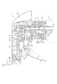
図1に示す本発明の一実施の形態であるトリガー式液体噴出器1は、例えば、カビ取り剤、洗剤、衣料用糊剤、住居用ワックス、整髪剤、芳香剤、忌避剤、農薬、薬品等の液体を収容する容器2の口部2aに取り付けて使用されるものである。このトリガー式液体噴出器1は、容器2の口部2aに装着される樹脂製の噴出器本体11と、この噴出器本体11に装着されたノズル21およびポンプ31を備えている。
A trigger type liquid ejector 1 according to an embodiment of the present invention shown in FIG. 1 includes, for example, a mold removing agent, a detergent, a clothing paste, a residential wax, a hairdressing agent, a fragrance, a repellent, an agricultural chemical, and a chemical. It attaches to the
噴出器本体11は、容器2の口部2aに対応した円筒状の装着筒部12を備え、この装着筒部12を容器2の口部2aに嵌合させた状態で装着キャップ13が容器2の口部2aにねじ結合されることにより、容器2の口部2aに装着されている。なお、符号14は、容器2の口部2aと装着筒部12との間を密封するシール部材である。
The
噴出器本体11は、装着筒部12からその中心軸に沿う方向に向けて延びる起立部15と、この起立部15に対して直交する方向に延びる延出部16とを備えた外形略L字形に形成されている。起立部15の内部には装着筒部12に連通する吸入流路P1が設けられ、この吸入流路P1の下端には容器2の内部に挿入される吸引用のチューブ17が接続されている。一方、延出部16には吸入流路P1に対して直交する方向に延びる送出流路P2が設けられ、この送出流路P2の先端はノズル21に連なる送出口18となっている。このように、噴出器本体11の液体の流路Pは吸入流路P1と送出流路P2とを含んで構成されている。
The ejector
噴出器本体11の延出部16の先端には円筒状の装着筒16aが設けられ、ノズル21は、この装着筒16aに抜け止めされた状態で装着されている。装着筒16aの内側には送出流路P2の送出口18が開口している。このように、ノズル21は送出流路P2の先端に装着され、送出流路P2を通して供給される液体を外部に向けて霧状または泡状として噴出させることができる。
A
なお、このノズル21を装着筒16aに回動可能に装着し、ノズル21を回動させることで当該ノズル21を、液体の噴出が可能な開状態と液体の噴出が不能な閉状態とに切り替え可能な構造とすることもできる。また、ノズル21は2ピース構造とすることができ、さらに、ノズル21に開閉自在にノズルカバー21aを設け、このノズルカバー21aをノズル21の前面を覆う閉位置として液体を噴出させることにより、ノズル21から噴出される液体をさらに効果的に泡状化させる構成とすることもできる。
The
ポンプ31は、噴出器本体11に取り付けられたシリンダ32と、このシリンダ32の内部に移動自在に組み付けられたピストン33とを備えている。噴出器本体11の液体の流路Pの途中部分つまり吸入流路P1と送出流路P2との間にはポンプ孔34が設けられ、シリンダ32の内部はこのポンプ孔34を介して流路Pつまり吸入流路P1および送出流路P2に接続されている。
The pump 31 includes a
噴出器本体11には枢軸41により回動自在にトリガー(操作レバー)Tが装着され、このトリガーTはピン部材42によりピストン33の先端に回動自在に連結されている。また、トリガーTには、一端が噴出器本体11に固定保持された湾曲形状の板ばね43の先端が係止され、この板ばね43により、トリガーTはポンプ31から離れる方向(図中においては枢軸を中心とした時計回り方向)に付勢されている。
A trigger (operating lever) T is rotatably mounted on the
なお、噴出器本体11にはカバー44が装着され、噴出器本体11とポンプ31はこのカバー44により覆われ、トリガーTがカバー44の下方から突出している。
The
トリガーTを手動で操作し、ポンプ31に向けて引くことにより、ピストン33をシリンダ32内に押し込んでポンプ31を吐出動作させることができる。また、トリガーTの操作を解除することにより、板ばね43の弾性力によりトリガーTを初期位置に復帰させてポンプ31を吸入動作させることができる。このように、トリガーTの引き操作と解除操作とを繰り返すことによりポンプ31を作動させ、容器2内の液体を、吸入流路P1を介してポンプ孔34からポンプ31内に吸入するとともに、ポンプ31に吸入した液体をポンプ孔34から送出流路P2つまりノズル21に向けて吐出することができる。
By manually operating the trigger T and pulling it toward the pump 31, the
なお、噴出器本体11およびポンプ31としては、上記した構成のものに限らず、トリガーTの操作により作動するポンプ31によって容器2の内部からノズル21に向けて液体を圧送することができる構成のものであれば、種々の構成ないし構造のものを用いることができる。
The
吸入流路P1とチューブ17の間には、このトリガー式液体噴出器1が装着された容器2が正立姿勢および倒立姿勢の何れの姿勢とされても、容器2内の液体をポンプ31に供給することを可能とする正倒立両用機構51が設けられている。
Between the suction flow path P1 and the tube 17, the liquid in the container 2 is supplied to the pump 31 regardless of whether the container 2 equipped with the trigger type liquid ejector 1 is in the upright position or the inverted position. A forward /
この正倒立両用機構51は逆止弁ユニット52を備え、容器2が正立姿勢のときにはボール状の弁体52aにより弁室52bの流出孔52cを閉塞して逆止弁ユニット52を閉状態とし、チューブ17を介して吸入流路P1に液体が導かれるようにする一方、容器2が倒立姿勢となったときには、弁体52aが弁室52b内を流出孔52cから離れる方向に移動して逆止弁ユニット52は開状態となり、装着筒部12の内側に溜まった液体を、逆止弁ユニット52の側壁に設けられた流入孔52dから弁室52b、流出孔52c、倒立時用流路52eを介して吸入流路P1に導くことができる。これにより、正立姿勢、倒立姿勢の何れの姿勢においても容器2内の液体をポンプ31に供給することができる。
This upside down
ポンプ31の作動に伴う流路Pの内部における液体の流れを、容器2側からノズル21側に向けた方向に規制するために、流路Pの内部には弁部材61が設けられている。図2、図3に示すように、この弁部材61は、固定部62、吸入側逆止弁63および吐出側逆止弁64を樹脂材料により一体に形成した構成とすることができる。
A
固定部62は円板状に形成され、流路P内のポンプ孔34の下流側(図1中においてポンプ孔34の上側)部分の内周面に設けられた段差部65に上方側から当接するとともにアンダーカット係合して流路P内に固定されている。また、固定部62には円柱状の連接部66が一体に設けられ、この連接部66の上端に同軸かつ一体に設けられた棒状部67が、流路P内の下方側を向く内壁に下方側から当接している。このように、固定部62は、その一端面が段差部65に上方側から当接するとともに、これと一体に設けられた棒状部67が流路Pの内壁に下方側から当接することにより流路P内に流路Pに沿って移動できないように固定されている。
The fixing
なお、固定部62は、上記構成に限らず、例えば流路P内に圧入や接着等の他の手段により固定される構成とすることもできる。
In addition, the fixing | fixed
図2、図3に示すように、固定部62は連接部66の外周面から径方向外側に突出する略T字形状に形成されている。これにより、流路P内に固定部62が固定されても、ポンプ孔34から送出流路P2へ向けた液体の流路が確保される。
As shown in FIGS. 2 and 3, the fixing
固定部62の下面には下方に向けて突出する弾性支持部68が一体に設けられ、この弾性支持部68の先端(下端)に吸入側逆止弁63が一体に設けられている。吸入側逆止弁63は、吸入流路P1の内径よりも外径が小さい円柱状に形成され、その下端は半球形状とされており、また、その下端の軸心には凹部63aが設けられている。一方、弾性支持部68は左右に湾曲する蛇行形状に形成されており、流路Pに沿って上下方向に弾性変形自在となっている。
An
吸入流路P1のポンプ孔34よりも上流側(容器2側)の内周面には、吸入流路P1の下方側に向けて縮径するテーパ面(円錐面)状に形成された弁座69が一体に設けられている。吸入側逆止弁63は、弾性支持部68により付勢された状態で、ポンプ孔34よりも上流側において弁座69にその上方側から当接して吸入流路P1を閉塞している。このような構成により、吸入側逆止弁63は、流路P内のポンプ孔34に対して上流側からの液体の流れ、つまり容器2側からポンプ31側に向けた吸入流路P1内の液体の流れは許容するが、吸入流路P1内のポンプ31側から容器2側に向けた液体の流れを阻止する逆止弁として機能する。
A valve seat formed in a tapered surface (conical surface) shape whose diameter is reduced toward the lower side of the suction flow path P1 on the inner peripheral surface on the upstream side (container 2 side) of the
一方、吐出側逆止弁64は、アンブレラバルブとも呼ばれるものであり、連接部66の上端から上方に向けて突出するとともに上方ほど外径が大きくなるように拡径する傘状に形成され、流路P内のポンプ孔34よりも下流側(図中上方側)に配置されている。吐出側逆止弁64は径方向に弾性変形自在となっており、その外周端において流路Pの内周面に接触して当該流路Pを閉塞している。なお、棒状部67はその基端側の一部が吐出側逆止弁64の内側に配置されている。吐出側逆止弁64は、その外周端が流路Pの内周面から離れるように縮径変形することにより、流路P内のポンプ孔34から下流側に向けた液体の流れ、つまり送出流路P2内のポンプ31側からノズル21側へ向けた液体の流れを許容するが、その外周端が流路Pの内周面に当接することにより、送出流路P2内のノズル21側からポンプ31側に向けた液体の流れを阻止する逆止弁として機能する。
On the other hand, the discharge-
このような弁部材61が流路P内に設けられることにより、ポンプ31の作動時における流路P内の液体の流れ方向が、容器2側からノズル21側に向けた方向に規制される。つまり、トリガーTが操作されてポンプ31が吐出動作すると、ポンプ31内の液体が加圧されてポンプ孔34から流路Pに吐出されるが、このとき、ポンプ孔34から流路P内に液体が吐出されると、この液体の圧力により吐出側逆止弁64が縮径方向に弾性変形して開かれ、液体はポンプ31からノズル21に向けて送出流路P2内を圧送される。一方、吸入側逆止弁63は弾性支持部68により弁座69に押し付けられた状態に維持されるので、ポンプ31側から容器2側に向けた液体の流れは吸入側逆止弁63により阻止される。したがって、ポンプ31の吐出動作により、ポンプ31内の液体を確実に容器2からノズル21に向けて圧送させることができる。
By providing such a
反対に、トリガーTの操作が解除されてポンプ31が吸入動作すると、ポンプ31内が負圧となって吸入側逆止弁63が弁座69から離れる方向に移動して開かれ、容器2内の液体が吸入流路P1とポンプ孔34を通してポンプ31(シリンダ32)内に吸入される。このとき、吐出側逆止弁64は閉じた状態に維持され、流路P内におけるノズル21側からポンプ31側に向けた液体の流れは吐出側逆止弁64により阻止される。したがって、ポンプ31の吸入動作により、容器2内の液体を確実にポンプ31に向けて吸入することができる。
On the contrary, when the operation of the trigger T is released and the pump 31 performs the suction operation, the pressure in the pump 31 becomes negative and the suction
図4は傘状部の流路の内周面に対する接触状態を説明するための断面図である。 FIG. 4 is a cross-sectional view for explaining a contact state of the umbrella-shaped portion with the inner peripheral surface of the flow path.
本発明では、上記のように、吐出側逆止弁64を、径方向に弾性変形自在の傘状に形成しているが、その最も外径が大きくなる外周端を、その全周に亘って流路Pの内周面に均一の接触圧で接触させるのではなく、当該接触圧が周方向で不均一となるようにアンバランスに接触させるようにしている。
In the present invention, as described above, the discharge-
例えば、図4に示す本実施の形態の場合では、吐出側逆止弁64の軸心を円筒状に形成された流路Pの軸心からずらすことで、図4中右側における吐出側逆止弁64の外周端の流路Pの内周面への当り代L1を、図4中左側における吐出側逆止弁64の外周端の流路Pの内周面への当り代L2よりも大きくして、吐出側逆止弁64の流路Pの内周面への接触圧を周方向で不均一となるようにしている。
For example, in the case of the present embodiment shown in FIG. 4, the discharge
吐出側逆止弁64の外周端を、接触圧が周方向で不均一となるように流路Pの内周面に接触させる構成としては、図4に示す構成に限らず、種々変更可能である。
The configuration in which the outer peripheral end of the discharge
例えば、図5(a)に示す変形例のように、吐出側逆止弁64を、その外周端の中心位置と連接部66に連なる最下端部分である内周端の中心位置とがずれた形状、つまり、その軸心が流路Pの軸心に対して傾斜する斜円錐状に形成することができる。この場合、連接部66から吐出側逆止弁64の外周端の周方向の各位置までの距離が相違することになるので、吐出側逆止弁64の外周端を、接触圧が周方向で不均一となるように流路Pの内周面に接触させることができる。なお、吐出側逆止弁64の外周端は、流路Pの軸心に対して垂直に形成されるのが好ましい。この場合、吐出側逆止弁64の外周端の流路Pの内周面への当り代は、全周で均一でも不均一でもよい。
For example, as in the modification shown in FIG. 5A, the center position of the outer peripheral end of the discharge-
また、例えば、図5(b)に示す変形例のように、吐出側逆止弁64を、その外周端が流路Pの軸方向に垂直な面に対して傾斜した形状に形成することもできる。この場合も、連接部66から吐出側逆止弁64の外周端の周方向の各位置までの距離が相違することになるので、吐出側逆止弁64の外周端を、接触圧が周方向で不均一となるように流路Pの内周面に接触させることができる。なお、この場合においても、吐出側逆止弁64の外周端の流路Pの内周面への当り代は、全周で均一でも不均一でもよい。
Further, for example, as in the modification shown in FIG. 5B, the discharge
このように、吐出側逆止弁64の外周端を、接触圧が周方向で不均一となるように流路Pの内周面に接触させる構成としたことにより、ポンプ31が吐出動作し、ポンプ31から吐出された液体の圧力が吐出側逆止弁64に加えられたときには、当該圧力により吐出側逆止弁64の全体が均一に縮径変形するのではなく、流路Pの内周面に対する接触圧が小さい部分から先に縮径変形することになる。つまり、吐出側逆止弁64に、変形し易い部分が設けられることになるので、当該変形し易い部分の変形をきっかけに吐出側逆止弁64の全体が、より小さな圧力で開かれることになる。したがって、吐出側逆止弁64の開放圧力が下がることになるので、トリガーTの操作によりポンプ31を作動させ、液体をノズル21から噴出させる際において、ポンプ31を作動させるために必要なトリガーTの操作力を低減させて、このトリガー式液体噴出器1の操作をより軽く、容易なものとすることができる。
As described above, the pump 31 is discharged by the configuration in which the outer peripheral end of the discharge-
本発明は前記実施の形態に限定されるものではなく、その要旨を逸脱しない範囲で種々変更可能であることはいうまでもない。 It goes without saying that the present invention is not limited to the above-described embodiment, and various modifications can be made without departing from the scope of the invention.
例えば、ポンプ31は、前記実施の形態に示した構造のものに限らず、トリガーTの操作により作動して、ポンプ孔34を通して流路Pとの間で液体を吸入、吐出することができる構造のものであれば、種々の構成のものを用いることができる。
For example, the pump 31 is not limited to the structure shown in the above embodiment, and can be operated by the operation of the trigger T and can suck and discharge liquid from and to the flow path P through the
また、吸入側逆止弁63も前記実施の形態に示した構造のものに限らず、吸入流路P1を開閉する逆止弁として機能することができるものであれば種々の構成とすることができる。
In addition, the suction
1 トリガー式液体噴出器
2 容器
2a 口部
11 噴出器本体
12 装着筒部
13 装着キャップ
14 シール部材
15 起立部
16 延出部
16a 装着筒
17 チューブ
18 送出口
21 ノズル
21a ノズルカバー
31 ポンプ
32 シリンダ
33 ピストン
34 ポンプ孔
41 枢軸
42 ピン部材
43 板ばね
44 カバー
51 正倒立両用機構
52 逆止弁ユニット
52a 弁体
52b 弁室
52c 流出孔
52d 流入孔
52e 倒立時用流路
61 弁部材
62 固定部
63 吸入側逆止弁
63a 凹部
64 吐出側逆止弁
65 段差部
66 連接部
67 棒状部
68 弾性支持部
69 弁座
P1 吸入流路
P2 送出流路
P 流路
T トリガー
L1 当り代
L2 当り代
DESCRIPTION OF SYMBOLS 1 Trigger type liquid ejector 2
Claims (6)
前記弁部材は、
前記流路内の前記ポンプ孔よりも上流側に配置されて該容器側から前記ポンプ側に向けた液体の流れを許容するとともに前記ポンプ側から前記容器側に向けた液体の流れを阻止する吸入側逆止弁と、
前記流路内の前記ポンプ孔よりも下流側に配置されて前記ポンプ側から前記ノズル側に向けた液体の流れを許容するとともに前記ノズル側から前記ポンプ側に向けた液体の流れを阻止する吐出側逆止弁と、を有し、
前記吐出側逆止弁は、径方向に弾性変形自在の傘状に形成され、その外周端において前記流路の内周面に接触するとともに、前記吐出側逆止弁の軸心が、前記流路の軸心からずらされていることにより、該外周端の前記流路の内周面への接触力が周方向で不均一とされていることを特徴とするトリガー式液体噴出器。 Connected to the ejector body mounted on the mouth of the container containing the liquid, the nozzle mounted on the tip of the flow path provided in the ejector body, and the pump hole provided in the middle part of the flow path A pump that operates by operating a trigger, a valve member that is provided in the flow path and regulates the flow of liquid in the flow path in accordance with the operation of the pump in a direction from the container toward the nozzle, A trigger type liquid ejector comprising:
The valve member is
Suction that is arranged on the upstream side of the pump hole in the flow path and allows the flow of liquid from the container side toward the pump side and prevents the liquid flow from the pump side toward the container side A side check valve,
Discharge that is arranged on the downstream side of the pump hole in the flow path and permits the flow of liquid from the pump side toward the nozzle side and prevents the liquid flow from the nozzle side toward the pump side. A side check valve,
The discharge-side check valve is formed in an umbrella shape that is elastically deformable in the radial direction, contacts the inner peripheral surface of the flow path at the outer peripheral end, and the axis of the discharge-side check valve A trigger type liquid ejector characterized in that the contact force of the outer peripheral end to the inner peripheral surface of the flow path is nonuniform in the circumferential direction by being shifted from the axial center of the path.
前記弁部材は、
前記流路内の前記ポンプ孔よりも上流側に配置されて該容器側から前記ポンプ側に向けた液体の流れを許容するとともに前記ポンプ側から前記容器側に向けた液体の流れを阻止する吸入側逆止弁と、
前記流路内の前記ポンプ孔よりも下流側に配置されて前記ポンプ側から前記ノズル側に向けた液体の流れを許容するとともに前記ノズル側から前記ポンプ側に向けた液体の流れを阻止する吐出側逆止弁と、を有し、
前記吐出側逆止弁は、径方向に弾性変形自在の傘状に形成され、その外周端において前記流路の内周面に接触するとともに、前記吐出側逆止弁が、その外周端の中心位置と内周端の中心位置とがずれた形状に形成されていることにより、該外周端の前記流路の内周面への接触力が周方向で不均一とされていることを特徴とするトリガー式液体噴出器。 Connected to the ejector body mounted on the mouth of the container containing the liquid, the nozzle mounted on the tip of the flow path provided in the ejector body, and the pump hole provided in the middle part of the flow path A pump that operates by operating a trigger, a valve member that is provided in the flow path and regulates the flow of liquid in the flow path in accordance with the operation of the pump in a direction from the container toward the nozzle, A trigger type liquid ejector comprising:
The valve member is
Suction that is arranged on the upstream side of the pump hole in the flow path and allows the flow of liquid from the container side toward the pump side and prevents the liquid flow from the pump side toward the container side A side check valve,
Discharge that is arranged on the downstream side of the pump hole in the flow path and permits the flow of liquid from the pump side toward the nozzle side and prevents the liquid flow from the nozzle side toward the pump side. A side check valve,
The discharge-side check valve is formed in an umbrella shape that is elastically deformable in the radial direction, and comes into contact with the inner peripheral surface of the flow path at the outer peripheral end, and the discharge-side check valve is at the center of the outer peripheral end. The contact force of the outer peripheral end to the inner peripheral surface of the flow path is nonuniform in the circumferential direction because the position and the center position of the inner peripheral end are shifted from each other. Trigger type liquid ejector.
前記弁部材は、
前記流路内の前記ポンプ孔よりも上流側に配置されて該容器側から前記ポンプ側に向けた液体の流れを許容するとともに前記ポンプ側から前記容器側に向けた液体の流れを阻止する吸入側逆止弁と、
前記流路内の前記ポンプ孔よりも下流側に配置されて前記ポンプ側から前記ノズル側に向けた液体の流れを許容するとともに前記ノズル側から前記ポンプ側に向けた液体の流れを阻止する吐出側逆止弁と、を有し、
前記吐出側逆止弁は、径方向に弾性変形自在の傘状に形成され、その外周端において前記流路の内周面に接触するとともに、前記吐出側逆止弁が、その外周端が前記流路の軸方向に垂直な面に対して傾斜した形状に形成されていることにより、該外周端の前記流路の内周面への接触力が周方向で不均一とされていることを特徴とするトリガー式液体噴出器。 Connected to the ejector body mounted on the mouth of the container containing the liquid, the nozzle mounted on the tip of the flow path provided in the ejector body, and the pump hole provided in the middle part of the flow path A pump that operates by operating a trigger, a valve member that is provided in the flow path and regulates the flow of liquid in the flow path in accordance with the operation of the pump in a direction from the container toward the nozzle, A trigger type liquid ejector comprising:
The valve member is
Suction that is arranged on the upstream side of the pump hole in the flow path and allows the flow of liquid from the container side toward the pump side and prevents the liquid flow from the pump side toward the container side A side check valve,
Discharge that is arranged on the downstream side of the pump hole in the flow path and permits the flow of liquid from the pump side toward the nozzle side and prevents the liquid flow from the nozzle side toward the pump side. A side check valve,
The discharge-side check valve is formed in an umbrella shape that is elastically deformable in the radial direction, and comes into contact with the inner peripheral surface of the flow path at the outer peripheral end, and the discharge-side check valve has the outer peripheral end at the outer peripheral end. It is formed in a shape inclined with respect to a surface perpendicular to the axial direction of the flow path, so that the contact force of the outer peripheral end to the inner peripheral surface of the flow path is uneven in the circumferential direction. Features a trigger type liquid ejector.
Priority Applications (8)
| Application Number | Priority Date | Filing Date | Title |
|---|---|---|---|
| JP2014113469A JP6258128B2 (en) | 2014-05-30 | 2014-05-30 | Trigger type liquid ejector |
| PCT/JP2015/002267 WO2015182041A1 (en) | 2014-05-30 | 2015-04-27 | Trigger-type liquid sprayer |
| CN201580025247.1A CN106457285B (en) | 2014-05-30 | 2015-04-27 | Trigger type liquid sprayer |
| CA2948886A CA2948886C (en) | 2014-05-30 | 2015-04-27 | Trigger-type liquid dispenser |
| KR1020167031824A KR101868260B1 (en) | 2014-05-30 | 2015-04-27 | Trigger-type liquid sprayer |
| EP15799828.7A EP3150287B1 (en) | 2014-05-30 | 2015-04-27 | Trigger-type liquid dispenser |
| US15/311,395 US10040087B2 (en) | 2014-05-30 | 2015-04-27 | Trigger-type liquid dispenser |
| AU2015265399A AU2015265399B2 (en) | 2014-05-30 | 2015-04-27 | Trigger-type liquid sprayer |
Applications Claiming Priority (1)
| Application Number | Priority Date | Filing Date | Title |
|---|---|---|---|
| JP2014113469A JP6258128B2 (en) | 2014-05-30 | 2014-05-30 | Trigger type liquid ejector |
Publications (2)
| Publication Number | Publication Date |
|---|---|
| JP2015226876A JP2015226876A (en) | 2015-12-17 |
| JP6258128B2 true JP6258128B2 (en) | 2018-01-10 |
Family
ID=54698403
Family Applications (1)
| Application Number | Title | Priority Date | Filing Date |
|---|---|---|---|
| JP2014113469A Expired - Fee Related JP6258128B2 (en) | 2014-05-30 | 2014-05-30 | Trigger type liquid ejector |
Country Status (8)
| Country | Link |
|---|---|
| US (1) | US10040087B2 (en) |
| EP (1) | EP3150287B1 (en) |
| JP (1) | JP6258128B2 (en) |
| KR (1) | KR101868260B1 (en) |
| CN (1) | CN106457285B (en) |
| AU (1) | AU2015265399B2 (en) |
| CA (1) | CA2948886C (en) |
| WO (1) | WO2015182041A1 (en) |
Families Citing this family (10)
| Publication number | Priority date | Publication date | Assignee | Title |
|---|---|---|---|---|
| JP6456687B2 (en) * | 2014-06-30 | 2019-01-23 | 株式会社吉野工業所 | Trigger type liquid ejector |
| JP6345095B2 (en) * | 2014-06-30 | 2018-06-20 | 株式会社吉野工業所 | Trigger type liquid ejector |
| JP6482436B2 (en) * | 2015-08-31 | 2019-03-13 | 株式会社吉野工業所 | Upside down adapter |
| US10518281B2 (en) * | 2016-05-31 | 2019-12-31 | Yoshino Kogyosho Co., Ltd. | Trigger-type ejector |
| JP6723093B2 (en) * | 2016-06-24 | 2020-07-15 | キャニヨン株式会社 | Accumulator spray base body and accumulator spray with base body |
| JP6833361B2 (en) * | 2016-06-24 | 2021-02-24 | キャニヨン株式会社 | Accumulation spray |
| KR101887397B1 (en) * | 2016-11-22 | 2018-09-21 | 주식회사 다린 | Spraying apparatus |
| CN106824603A (en) * | 2017-02-10 | 2017-06-13 | 昆山希安思塑料制品有限公司 | Sprayer unit |
| JP6792534B2 (en) * | 2017-10-11 | 2020-11-25 | 株式会社ニフコ | Fluid discharge mechanism and fluid spraying device for vehicle cameras or sensors |
| JP7118371B2 (en) * | 2018-09-11 | 2022-08-16 | キャニヨン株式会社 | trigger pump dispenser |
Family Cites Families (12)
| Publication number | Priority date | Publication date | Assignee | Title |
|---|---|---|---|---|
| SE333624B (en) * | 1969-07-28 | 1971-03-22 | Perpedos Ab | |
| DE2025940C3 (en) * | 1970-05-27 | 1978-06-01 | Robert Bosch Gmbh, 7000 Stuttgart | check valve |
| US4527741A (en) * | 1983-06-13 | 1985-07-09 | The Afa Corporation | Trigger pump sprayer |
| GB2146740B (en) * | 1983-09-15 | 1986-10-22 | Grundy | Non-return valve |
| US4610275A (en) * | 1985-11-04 | 1986-09-09 | Beecher William H | Valve for relieving pressure or checking reverse flow |
| JPS647583A (en) | 1987-06-30 | 1989-01-11 | Nec Corp | Light amplifier |
| JP3647583B2 (en) * | 1996-11-25 | 2005-05-11 | 株式会社吉野工業所 | Valve member of trigger type liquid ejector |
| JP3906953B2 (en) * | 1998-03-30 | 2007-04-18 | 株式会社資生堂 | Spray container |
| US6116472A (en) * | 1998-12-15 | 2000-09-12 | Calmar Inc. | Trigger acutated pump sprayer |
| SE522313C2 (en) * | 2000-01-04 | 2004-02-03 | Mats Persson | Methods and apparatus for providing one-way flow |
| US20020066802A1 (en) * | 2000-12-05 | 2002-06-06 | Tetsuya Tada | Trigger spray and container provided with trigger spray |
| JP2013056697A (en) * | 2011-09-08 | 2013-03-28 | Tetsuya Tada | Accumulation-type trigger sprayer and accumulator valve |
-
2014
- 2014-05-30 JP JP2014113469A patent/JP6258128B2/en not_active Expired - Fee Related
-
2015
- 2015-04-27 CN CN201580025247.1A patent/CN106457285B/en active Active
- 2015-04-27 WO PCT/JP2015/002267 patent/WO2015182041A1/en active Application Filing
- 2015-04-27 KR KR1020167031824A patent/KR101868260B1/en active IP Right Grant
- 2015-04-27 AU AU2015265399A patent/AU2015265399B2/en not_active Ceased
- 2015-04-27 CA CA2948886A patent/CA2948886C/en active Active
- 2015-04-27 EP EP15799828.7A patent/EP3150287B1/en active Active
- 2015-04-27 US US15/311,395 patent/US10040087B2/en active Active
Also Published As
| Publication number | Publication date |
|---|---|
| EP3150287A4 (en) | 2018-01-10 |
| CN106457285B (en) | 2019-06-25 |
| JP2015226876A (en) | 2015-12-17 |
| US10040087B2 (en) | 2018-08-07 |
| EP3150287B1 (en) | 2020-07-29 |
| US20170113238A1 (en) | 2017-04-27 |
| AU2015265399B2 (en) | 2018-01-04 |
| KR101868260B1 (en) | 2018-06-15 |
| CA2948886C (en) | 2018-09-18 |
| AU2015265399A1 (en) | 2016-12-08 |
| KR20160145714A (en) | 2016-12-20 |
| CA2948886A1 (en) | 2015-12-03 |
| WO2015182041A1 (en) | 2015-12-03 |
| CN106457285A (en) | 2017-02-22 |
| EP3150287A1 (en) | 2017-04-05 |
Similar Documents
| Publication | Publication Date | Title |
|---|---|---|
| JP6258128B2 (en) | Trigger type liquid ejector | |
| US11154889B2 (en) | Sprayer for liquids with precompression chamber | |
| US8365962B2 (en) | Lever spray pump | |
| US7891583B2 (en) | Dome pump spray assembly | |
| JP6404100B2 (en) | Trigger type liquid ejector | |
| WO2015129268A1 (en) | Trigger-type fluid jetting device | |
| JP6486146B2 (en) | Trigger type liquid ejector | |
| JP6404115B2 (en) | Trigger type liquid ejector | |
| JP6121308B2 (en) | Trigger type liquid ejector | |
| JP6345095B2 (en) | Trigger type liquid ejector | |
| JP6576300B2 (en) | Trigger type ejector | |
| JP6153823B2 (en) | Trigger type liquid ejector | |
| WO2017208630A1 (en) | Trigger sprayer | |
| JP6158045B2 (en) | Trigger type liquid ejector | |
| JP7345984B2 (en) | trigger type liquid squirt | |
| JP6033747B2 (en) | Trigger type liquid ejector | |
| JP6612181B2 (en) | Trigger type ejector | |
| JP6219163B2 (en) | Trigger type liquid ejector | |
| JP6395661B2 (en) | Liquid ejector | |
| JP6667963B2 (en) | Trigger type ejector | |
| JP4511856B2 (en) | Ejection device and ejector |
Legal Events
| Date | Code | Title | Description |
|---|---|---|---|
| A621 | Written request for application examination |
Free format text: JAPANESE INTERMEDIATE CODE: A621 Effective date: 20161128 |
|
| A131 | Notification of reasons for refusal |
Free format text: JAPANESE INTERMEDIATE CODE: A131 Effective date: 20170815 |
|
| A521 | Request for written amendment filed |
Free format text: JAPANESE INTERMEDIATE CODE: A523 Effective date: 20171002 |
|
| TRDD | Decision of grant or rejection written | ||
| A01 | Written decision to grant a patent or to grant a registration (utility model) |
Free format text: JAPANESE INTERMEDIATE CODE: A01 Effective date: 20171205 |
|
| A61 | First payment of annual fees (during grant procedure) |
Free format text: JAPANESE INTERMEDIATE CODE: A61 Effective date: 20171206 |
|
| R150 | Certificate of patent or registration of utility model |
Ref document number: 6258128 Country of ref document: JP Free format text: JAPANESE INTERMEDIATE CODE: R150 |
|
| LAPS | Cancellation because of no payment of annual fees |