JP6254468B2 - General purpose engine - Google Patents
General purpose engine Download PDFInfo
- Publication number
- JP6254468B2 JP6254468B2 JP2014060391A JP2014060391A JP6254468B2 JP 6254468 B2 JP6254468 B2 JP 6254468B2 JP 2014060391 A JP2014060391 A JP 2014060391A JP 2014060391 A JP2014060391 A JP 2014060391A JP 6254468 B2 JP6254468 B2 JP 6254468B2
- Authority
- JP
- Japan
- Prior art keywords
- valve
- chamber
- crank chamber
- gasket
- oil
- Prior art date
- Legal status (The legal status is an assumption and is not a legal conclusion. Google has not performed a legal analysis and makes no representation as to the accuracy of the status listed.)
- Expired - Fee Related
Links
Images


Classifications
-
- F—MECHANICAL ENGINEERING; LIGHTING; HEATING; WEAPONS; BLASTING
- F01—MACHINES OR ENGINES IN GENERAL; ENGINE PLANTS IN GENERAL; STEAM ENGINES
- F01M—LUBRICATING OF MACHINES OR ENGINES IN GENERAL; LUBRICATING INTERNAL COMBUSTION ENGINES; CRANKCASE VENTILATING
- F01M11/00—Component parts, details or accessories, not provided for in, or of interest apart from, groups F01M1/00 - F01M9/00
- F01M11/02—Arrangements of lubricant conduits
-
- F—MECHANICAL ENGINEERING; LIGHTING; HEATING; WEAPONS; BLASTING
- F01—MACHINES OR ENGINES IN GENERAL; ENGINE PLANTS IN GENERAL; STEAM ENGINES
- F01M—LUBRICATING OF MACHINES OR ENGINES IN GENERAL; LUBRICATING INTERNAL COMBUSTION ENGINES; CRANKCASE VENTILATING
- F01M1/00—Pressure lubrication
- F01M1/04—Pressure lubrication using pressure in working cylinder or crankcase to operate lubricant feeding devices
-
- F—MECHANICAL ENGINEERING; LIGHTING; HEATING; WEAPONS; BLASTING
- F01—MACHINES OR ENGINES IN GENERAL; ENGINE PLANTS IN GENERAL; STEAM ENGINES
- F01M—LUBRICATING OF MACHINES OR ENGINES IN GENERAL; LUBRICATING INTERNAL COMBUSTION ENGINES; CRANKCASE VENTILATING
- F01M11/00—Component parts, details or accessories, not provided for in, or of interest apart from, groups F01M1/00 - F01M9/00
- F01M11/0004—Oilsumps
-
- F—MECHANICAL ENGINEERING; LIGHTING; HEATING; WEAPONS; BLASTING
- F01—MACHINES OR ENGINES IN GENERAL; ENGINE PLANTS IN GENERAL; STEAM ENGINES
- F01M—LUBRICATING OF MACHINES OR ENGINES IN GENERAL; LUBRICATING INTERNAL COMBUSTION ENGINES; CRANKCASE VENTILATING
- F01M11/00—Component parts, details or accessories, not provided for in, or of interest apart from, groups F01M1/00 - F01M9/00
- F01M11/06—Means for keeping lubricant level constant or for accommodating movement or position of machines or engines
- F01M11/062—Accommodating movement or position of machines or engines, e.g. dry sumps
-
- F—MECHANICAL ENGINEERING; LIGHTING; HEATING; WEAPONS; BLASTING
- F01—MACHINES OR ENGINES IN GENERAL; ENGINE PLANTS IN GENERAL; STEAM ENGINES
- F01M—LUBRICATING OF MACHINES OR ENGINES IN GENERAL; LUBRICATING INTERNAL COMBUSTION ENGINES; CRANKCASE VENTILATING
- F01M9/00—Lubrication means having pertinent characteristics not provided for in, or of interest apart from, groups F01M1/00 - F01M7/00
- F01M9/06—Dip or splash lubrication
-
- F—MECHANICAL ENGINEERING; LIGHTING; HEATING; WEAPONS; BLASTING
- F01—MACHINES OR ENGINES IN GENERAL; ENGINE PLANTS IN GENERAL; STEAM ENGINES
- F01M—LUBRICATING OF MACHINES OR ENGINES IN GENERAL; LUBRICATING INTERNAL COMBUSTION ENGINES; CRANKCASE VENTILATING
- F01M9/00—Lubrication means having pertinent characteristics not provided for in, or of interest apart from, groups F01M1/00 - F01M7/00
- F01M9/10—Lubrication of valve gear or auxiliaries
- F01M9/105—Lubrication of valve gear or auxiliaries using distribution conduits
-
- F—MECHANICAL ENGINEERING; LIGHTING; HEATING; WEAPONS; BLASTING
- F01—MACHINES OR ENGINES IN GENERAL; ENGINE PLANTS IN GENERAL; STEAM ENGINES
- F01M—LUBRICATING OF MACHINES OR ENGINES IN GENERAL; LUBRICATING INTERNAL COMBUSTION ENGINES; CRANKCASE VENTILATING
- F01M9/00—Lubrication means having pertinent characteristics not provided for in, or of interest apart from, groups F01M1/00 - F01M7/00
- F01M9/12—Non-pressurised lubrication, or non-closed-circuit lubrication, not otherwise provided for
-
- F—MECHANICAL ENGINEERING; LIGHTING; HEATING; WEAPONS; BLASTING
- F01—MACHINES OR ENGINES IN GENERAL; ENGINE PLANTS IN GENERAL; STEAM ENGINES
- F01M—LUBRICATING OF MACHINES OR ENGINES IN GENERAL; LUBRICATING INTERNAL COMBUSTION ENGINES; CRANKCASE VENTILATING
- F01M11/00—Component parts, details or accessories, not provided for in, or of interest apart from, groups F01M1/00 - F01M9/00
- F01M11/0004—Oilsumps
- F01M2011/0033—Oilsumps with special means for guiding the return of oil into the sump
-
- F—MECHANICAL ENGINEERING; LIGHTING; HEATING; WEAPONS; BLASTING
- F01—MACHINES OR ENGINES IN GENERAL; ENGINE PLANTS IN GENERAL; STEAM ENGINES
- F01M—LUBRICATING OF MACHINES OR ENGINES IN GENERAL; LUBRICATING INTERNAL COMBUSTION ENGINES; CRANKCASE VENTILATING
- F01M11/00—Component parts, details or accessories, not provided for in, or of interest apart from, groups F01M1/00 - F01M9/00
- F01M11/02—Arrangements of lubricant conduits
- F01M2011/021—Arrangements of lubricant conduits for lubricating auxiliaries, e.g. pumps or turbo chargers
Landscapes
- Engineering & Computer Science (AREA)
- Mechanical Engineering (AREA)
- General Engineering & Computer Science (AREA)
- Lubrication Of Internal Combustion Engines (AREA)
- Cylinder Crankcases Of Internal Combustion Engines (AREA)
Description
本発明は,芝刈機等,各種作業機の動力に使用される汎用エンジン,特に,底部に据え付けフランジを有するクランクケースと,このクランクケースの一側から傾斜して延びるシリンダブロックと,このシリンダブロックの端面にガスケットを介して接合されるシリンダヘッドとを備え,クランクケース内のクランク室には,このクランク室の貯留潤滑オイルを飛散させてエンジン各部の潤滑のためのオイル飛沫を発生させるオイル飛沫発生手段を設け,シリンダブロック及びシリンダヘッドの上側部及び下側部には,クランク室と,シリンダヘッド内の動弁室との間を連通する上部油路及び下部油路をそれぞれ設けた汎用エンジンの改良に関する。 The present invention relates to a general-purpose engine used for powering various working machines such as lawn mowers, in particular, a crankcase having a mounting flange at the bottom, a cylinder block extending obliquely from one side of the crankcase, and the cylinder block And a cylinder head joined to the end face of the engine through a gasket. The crankcase in the crankcase has an oil splash that scatters the stored lubricating oil in the crankcase and generates oil splashes for lubricating parts of the engine. General-purpose engine provided with generating means, and provided with an upper oil passage and a lower oil passage communicating with the crank chamber and the valve operating chamber in the cylinder head at the upper and lower portions of the cylinder block and cylinder head, respectively. Regarding improvements.
かゝる汎用エンジンは,例えば特許文献1に開示されるように,既に知られている。 Such a general-purpose engine is already known as disclosed in Patent Document 1, for example.
この種の汎用エンジンでは,作業機の使用状況によっては,傾斜したシリンダブロックが更に傾斜した状態とされることがあり,この場合,クランク室の貯留オイルが下部油路を通して動弁室に大量に流れ込むことにより,クランク室のオイルの貯留量が大きく減少し,オイル飛沫発生手段によるオイル飛沫の発生が不充分となり,エンジン各部の潤滑に支障を来すことがある。 In this type of general-purpose engine, the tilted cylinder block may be further tilted depending on the use condition of the work implement. In this case, a large amount of stored oil in the crank chamber passes through the lower oil passage to the valve operating chamber. By flowing in, the amount of oil stored in the crankcase is greatly reduced, and the generation of oil droplets by the oil droplet generation means becomes insufficient, which may hinder the lubrication of each part of the engine.
本発明は,かゝる事情に鑑みてなされたもので,傾斜したシリンダブロックが更に傾斜した状態とされ,クランク室の貯留オイルが下部油路を通して動弁室に流れ込んでも,これを直ちにクランク室に押し戻して,クランク室のオイル貯留量を確保し,エンジン各部の潤滑に支障を来さないようにした前記汎用エンジンを提供することを目的とする。 The present invention has been made in view of such circumstances, and even if the inclined cylinder block is further inclined, even if the stored oil in the crank chamber flows into the valve operating chamber through the lower oil passage, this is immediately applied to the crank chamber. It is an object of the present invention to provide the general-purpose engine which is pushed back to ensure that the amount of oil stored in the crank chamber is secured and does not hinder the lubrication of each part of the engine.
上記目的を達成するために,本発明は,底部に据え付けフランジを有するクランクケースと,このクランクケースの一側から傾斜して延びるシリンダブロックと,このシリンダブロックの端面にガスケットを介して接合されるシリンダヘッドとを備え,クランクケース内のクランク室には,このクランク室の貯留潤滑オイルを飛散させてエンジン各部の潤滑のためのオイル飛沫を発生させるオイル飛沫発生手段を設け,シリンダブロック及びシリンダヘッドの上側部及び下側部には,クランク室と,シリンダヘッド内の動弁室との間を連通する上部油路及び下部油路をそれぞれ設けた汎用エンジンにおいて,前記上部油路を,シリンダブロック及びシリンダヘッド間に介装される前記ガスケットにより,クランク室側の上流路と動弁室側の下流路とに分け,前記ガスケットに,弁取り付け孔と,この弁取り付け孔を囲むように並んで前記上流路及び下流路間を連通する複数の通孔とを設け,前記下流路に臨む前記ガスケットの上面に着座して前記通孔群を覆う弾性傘部,及びこの弾性傘部のボス部から突出して前記弁取り付け孔を貫通する杆部よりなる弁体と,前記杆部に嵌合,固定されることで前記ボス部と協働して前記ガスケットを挟持する保持部材とで,前記上部油路に介装されてクランク室側から動弁室側への流体の流れを許容するがその逆の流れを阻止する一方向弁を構成し,傾斜したシリンダブロックが更に傾斜するようにエンジンが傾斜することにより,クランク室の貯留潤滑オイルが前記下部油路を通して動弁室に流入した場合には,クランク室から前記一方向弁を介して動弁室に伝達される正圧力により,動弁室への流入オイルを前記下部油路を通してクランク室に押し戻すようにしたことを第1の特徴とする。尚,前記オイル飛沫発生手段は,後述する本発明の実施形態中のオイルディッパ24に対応する。
In order to achieve the above object, the present invention is joined to a crankcase having a mounting flange at the bottom, a cylinder block extending inclined from one side of the crankcase, and an end surface of the cylinder block via a gasket. A cylinder head, and a crank chamber in the crankcase is provided with oil splash generating means for splashing the stored lubricating oil in the crank chamber to generate oil splash for lubricating each part of the engine. In the general-purpose engine provided with an upper oil passage and a lower oil passage respectively communicating between the crank chamber and the valve operating chamber in the cylinder head, the upper oil passage is connected to the cylinder block. And the gasket interposed between the cylinder heads, the upper flow path on the crank chamber side and the lower The gasket is provided with a valve mounting hole and a plurality of through holes communicating with the upper flow path and the lower flow path so as to surround the valve mounting hole, and the gasket facing the lower flow path is provided. A valve body comprising an elastic umbrella portion that sits on the upper surface and covers the through hole group, and a flange portion that protrudes from a boss portion of the elastic umbrella portion and penetrates the valve mounting hole, and is fitted and fixed to the flange portion. in the holding member in cooperation with the boss in Rukoto sandwiching the gasket, reverse pixel to permit fluid flow into the valve operating chamber side is interposed to the upper oil passage from the crank chamber side When the stored lubricating oil in the crank chamber flows into the valve chamber through the lower oil passage by tilting the engine so that the tilted cylinder block is further tilted, a one-way valve is formed. , The one-way valve from the crank chamber The positive pressure is transmitted to the valve operating chamber through, the first characterized in that the inflow oil to the valve-operating chamber and to push back into the crank chamber through the lower oil passage. The oil splash generating means corresponds to an
また本発明は,第1の特徴に加えて,前記杆部を,その外周面が前記弁取り付け孔の内周面に接触しないよう大径に形成する一方,前記保持部材には,複数の前記通孔に係合して前記杆部を前記弁取り付け孔との同心位置に保持する複数の位置決め爪を設けたことを第2の特徴とする。 The present invention, in addition to the first feature, a pre-Symbol rod portions, while the outer peripheral surface thereof is formed in a large diameter so as not to contact with the inner peripheral surface of the valve mounting hole, said holding member has a plurality of A second feature is that a plurality of positioning claws are provided to engage with the through hole and hold the flange portion in a concentric position with the valve mounting hole.
さらにまた本発明は,第1又は第2の特徴に加えて,前記杆部を,前記ボス部から延びて前記保持部材の嵌合孔に嵌合する第1軸部と,この第1軸部に膨大部を介して同軸に連なる,第1軸部よりも小径の第2軸部とより構成し,前記膨大部は,保持部材の背面に係合して保持部材を前記第1軸部上に保持するよう,第1軸部より大径に形成されることを第3の特徴とする。 Furthermore, in addition to the first or second feature, the present invention includes a first shaft portion that extends from the boss portion and fits into the fitting hole of the holding member, and the first shaft portion. And a second shaft portion having a diameter smaller than that of the first shaft portion. The enormous portion engages with the back surface of the holding member to place the holding member on the first shaft portion. The third feature is that the first shaft portion is formed to have a larger diameter so as to be held at the same position.
本発明の第1の特徴によれば,エンジンが,作業機の使用状況により,傾斜したシリンダブロックを更に大きく傾斜させた姿勢をとるように強制され,クランク室のオイルが下部油路を通して動弁室に大量に流入しても,エンジンの運転により,上部油路では,一方向弁の作用により,クランク室で発生する脈動圧力のうちの正圧力が上部油路を通過して動弁室に伝達されることで,動弁室の圧力が高まり,動弁室に流入したオイルを下部油路を通してクランク室に押し戻すことができる。したがって,クランク室のオイルの貯留量の減少を防ぎ,常にオイル飛沫発生手段によるオイル飛沫の生成を可能にし,エンジン各部の良好な潤滑状態を確保することができる。 According to the first aspect of the present invention, the engine is forced to take a posture in which the inclined cylinder block is further inclined according to the use state of the work machine, and the oil in the crank chamber is driven through the lower oil passage. Even if a large amount flows into the chamber, due to the operation of the engine, the positive pressure of the pulsating pressure generated in the crank chamber passes through the upper oil passage in the upper oil passage due to the action of the one-way valve. By being transmitted, the pressure in the valve chamber increases, and the oil flowing into the valve chamber can be pushed back to the crank chamber through the lower oil passage. Therefore, it is possible to prevent a decrease in the amount of oil stored in the crank chamber, to always generate oil splashes by the oil splash generating means, and to ensure a good lubrication state of each part of the engine.
また,ガスケットを利用して一方向弁を簡単に取り付けることができ,従来のエンジンに大幅な改造を加えることなく,この一方向弁を採用することができ,その改善コストを低く抑えることができる。 In addition , a one-way valve can be easily installed using a gasket, and this one-way valve can be adopted without significant modifications to the conventional engine, and the cost of improvement can be kept low. .
本発明の第2の特徴によれば,弁体の杆部は,その全周にわたり弁取り付け孔の内周面と一定の距離を置き,接触することがなく,したがって杆部が,肉厚が薄いガスケットの弁取り付け孔の鋭利な内周縁に接触することによる損傷を防ぎ,その耐久性を保持することができる。しかも正圧力を通過させる通孔を利用して,位置決め爪を係合させるので,ガスケットに特別な位置決め孔を設ける必要がなく,構造の簡素化に寄与し得る。 According to the second feature of the present invention, the flange portion of the valve body is placed at a certain distance from the inner peripheral surface of the valve mounting hole over the entire circumference thereof, and does not come into contact therewith. Damage due to contact with the sharp inner periphery of the valve mounting hole of the thin gasket can be prevented and its durability can be maintained. In addition, since the positioning claw is engaged using a through hole that allows a positive pressure to pass through, it is not necessary to provide a special positioning hole in the gasket, which can contribute to simplification of the structure.
本発明の第3の特徴によれば,一方向弁の組立性を良好にすることができる。 According to the 3rd characteristic of this invention, the assembly property of a one-way valve can be made favorable.
本発明の実施形態を添付図面に基づいて以下に説明する。 Embodiments of the present invention will be described below with reference to the accompanying drawings.
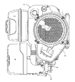
図1及び図2において,汎用エンジンEは,底部に据え付けフランジ1を有するクランクケース2と,このクランクケース2の一側から傾斜して延びるシリンダブロック3と,このシリンダブロック3の端面にガスケット4を介して接合されるシリンダヘッド5とを備えており,クランクケース2の上部には燃料タンクTが,またシリンダブロック3の上部にはエアクリーナAがそれぞれ取り付けられる。据え付けフランジ1は,この汎用エンジンEを動力とする作業機に据え付けられる。
1 and 2, the general-purpose engine E includes a crankcase 2 having a mounting flange 1 at the bottom, a cylinder block 3 extending obliquely from one side of the crankcase 2, and a
クランクケース2内のクランク室13にはクランク軸7が配設され,このクランク軸7は,シリンダブロック3のシリンダボア3aに嵌装されるピストン8にコンロッド9を介して連接される。またシリンダヘッド5には,シリンダボア3aに連なる燃焼室10と,この燃焼室10に開口する吸気ポート11i及び排気ポート(図示せず)が形成されると共に,吸気ポート11i及び排気ポートをそれぞれ開閉する吸気弁12i及び排気弁(図示せず)が設けられる。シリンダヘッド5内の動弁室14には,上記吸気弁12i及び排気弁を開閉駆動する動弁装置15の吸気用ロッカアーム18i及び排気用ロッカアーム(図示せず)が配設される。これら吸気用ロッカアーム18i及び排気用ロッカアームは,クランク室13に配設されてクランク軸7から減速駆動されるカム軸17により,吸気用プッシュロッド19i及び排気用プッシュロッド(図示せず)を介して揺動され,吸気弁12i及び排気弁を開閉するようになっている。吸気用プッシュロッド19i及び排気用プッシュロッドは,シリンダブロック3の下側部を通るように配置される。
A crankshaft 7 is disposed in a crank chamber 13 in the crankcase 2, and the crankshaft 7 is connected to a
クランク室13には,潤滑オイル23が下部油路21には達しない一定レベルに貯留されており,そのオイル23を飛散させてオイル飛沫を発生させるオイルディッパ24がコンロッド9の大端部に付設される。
In the crank chamber 13, lubricating
またシリンダブロック3及びシリンダヘッド5の上側部及び下側部には,シリンダブロック3及びシリンダヘッド5間のガスケット4を貫通してクランク室13及び動弁室14間を連通する上部油路20及び下部油路21がそれぞれ設けられ,下部油路21は,前記吸気用プッシュロッド19i及び排気用プッシュロッドの中間に配置される。
Further, an
上部油路20には,クランク室13側から動弁室14側への流体の流れを許容するが,その逆の流れを阻止する一方向弁Vが介装される。この一方向弁Vは,ガスケット4に次のように取り付けられる。
The
図3及び図4に示すように,ガスケット4は,上部油路20を,クランク室13側の上流路20aと動弁室14側の下流路20bとに分ける。このガスケット4には,弁取り付け孔25と,この弁取り付け孔25を囲むように並んで上流路20a及び下流路20b間を連通する複数(図示例では3個)の通孔26とが設けられる。
As shown in FIGS. 3 and 4, the
一方向弁Vは,ゴム等の弾性材製の弁体28及び合成樹脂製の保持部材29よりなっている。その弁体28は,弾性傘部30と,この弾性傘部30の中心に形成されてガスケット4側に突出するボス部31と,このボス部31から延出した杆部32とより構成され,またその杆部32は,ボス部31から延びて前記弁取り付け孔25よりも充分に小径の第1軸部32aと,この第1軸部32aに膨大部32cを介して同軸に連なる,第1軸部32aよりも小径の第2軸部32bとより構成される。この弁体28は,杆部32が弁取り付け孔25に挿入され,そして傘部30が下流路20bに臨むガスケット4の上面4aに着座するように配置される。
The one-way valve V includes a
保持部材29は,中心部に嵌合孔34を有し,また外周に前記通孔26と同数で軸方向に突出する位置決め爪35を有する。
The
この保持部材29の上記弁体28との結合に際しては,弁体28の第2軸部32bを,嵌合孔34に挿入してから牽引しながら,保持部材29を第1軸部32a側へ押圧する。すると,膨大部32cが伸びて小径化するので,保持部材29の嵌合孔34が膨大部32cを通過して第1軸部32aと嵌合することができる。その後,第2軸部32bの牽引を解除すると,膨大部32cは大径の原形に復して保持部材29の背面に係合し,保持部材29を第1軸部32aとの嵌合位置に保持する。第1軸部32aと嵌合した保持部材29は,弁体28のボス部31と協働してガスケット4を挟持することになる。
When the
このとき,保持部材29の複数の位置決め爪35は,ガスケット4の複数の通孔26と係合することにより,杆部32を弁取り付け孔25との同心位置に保持するようになっており,これにより,弁取り付け孔25よりも充分に小径の第1軸部32aは,その全周にわたり弁取り付け孔25の内周面と一定の距離を置き,接触することを回避される。
At this time, the plurality of
尚,図示しないが,動弁室14の上部には,ブローバイガスを吸入系に排出するためのブリーザパイプが接続されている。
Although not shown, a breather pipe for discharging blow-by gas to the suction system is connected to the upper part of the
次に,この実施形態の作用について説明する。 Next, the operation of this embodiment will be described.
汎用エンジンEが,据え付けフランジ1を水平にした通常な姿勢で運転しているときは,クランク室13の貯留オイル23は,下部油路21には達しておらず,クランク軸7の回転に伴ない揺動するオイルディッパ24がその貯留オイル23を叩き,飛散させてオイル飛沫をつくり,このオイル飛沫によりピストン8及びコンロッド9周りを潤滑し,またオイル飛沫は,上部油路20及び下部油路21を通過して動弁室14に達し,動弁装置15をも潤滑する。
When the general-purpose engine E is operating in a normal posture with the installation flange 1 being horizontal, the stored
特に,上部油路20には,クランク室13側から動弁室14側への流体の流れを許容するが,その逆の流れを阻止する一方向弁Vが介装されているので,ピストン8の往復運動に伴ないクランク室13に発生する脈動圧力のうち,正圧力のみが上部油路20を通過することができ,その正圧力に乗ってオイル飛沫が動弁室14に運ばれることになる。
In particular, the
即ち,クランク室13に発生する脈動圧力のうち,正圧力がガスケット4の通孔26から一方向弁Vの弾性傘部30に作用すると,弾性傘部30は押し開けられ,正圧力が上部油路20を通過するのを許容し,また負圧力が通孔26から弾性傘部30に作用すると,弾性傘部30はガスケット4側に引きつけられ,その上面4aに着座して通孔26を閉じ,負圧力が上部油路20を通過するのを阻止する。こうして,正圧力のみが上部油路20を通過するのである。
That is, of the pulsating pressure generated in the crank chamber 13, when a positive pressure acts on the
いま,この汎用エンジンEが,作業機の使用状況により,傾斜したシリンダブロック3を更に大きく傾斜させた姿勢をとるように強制されたとすると,クランク室13のオイル23が下部油路21を通して動弁室14に大量に流入することになる。しかしながら,汎用エンジンEが運転されゝば,上述のように,上部油路20では,一方向弁Vの作用により,クランク室13で発生する脈動圧力のうちの正圧力が上部油路20を通過して動弁室14に伝達されるので,動弁室14の圧力が高まり,動弁室14に流入したオイル23を下部油路21を通してクランク室13に押し戻すことができる。したがって,クランク室13のオイル23の貯留量の減少を防ぎ,常にオイルディッパ24によるオイル飛沫の生成を可能にし,エンジン各部の良好な潤滑状態を確保することができる。
Now, assuming that the general-purpose engine E is forced to take a posture in which the inclined cylinder block 3 is further inclined according to the use state of the work implement, the
ところで,シリンダブロック3及びシリンダヘッド5間に介装されるガスケット4には,弁取り付け孔25と,この弁取り付け孔25を囲むように並ぶ複数の上部油路20に連通する通孔26とを設けられ,上記一方向弁Vは,上部油路20の下流路20bに臨むガスケット4の上面4aに着座して通孔26群を覆う弾性傘部30,及びこの弾性傘部30のボス部31から突出して弁取り付け孔25を貫通する杆部32よりなる弁体28と,杆部32に嵌合,固定されることで,ボス部31と協働してガスケット4を挟持する保持部材29とで構成されるので,ガスケット4を利用して一方向弁Vを簡単に取り付けることができ,従来の汎用エンジンに大幅な改造を加えることなく,この一方向弁Vを採用することができ,その改善コストを低く抑えることができる。
By the way, the
またその際,弁体28の杆部32は,その外周面が前記弁取り付け孔25の内周面に接触しないよう小径に形成される一方,保持部材29の複数の位置決め爪35が,ガスケット4の通孔26に係合して杆部32を弁取り付け孔25との同心位置に保持するので,杆部32は,その全周にわたり弁取り付け孔25の内周面と一定の距離を置き,接触することがなく,したがって杆部32が,肉厚が薄いガスケット4の弁取り付け孔25の鋭利な内周縁に接触することによる損傷を防ぎ,その耐久性を保持することができる。しかも正圧力を通過させる通孔26を利用して,位置決め爪35を係合させるので,ガスケット4に特別な位置決め孔を設ける必要がなく,構造の簡素化に寄与し得る。
At this time, the
また上記杆部32は,傘部30のボス部31から延びて保持部材29の嵌合孔34に嵌合する第1軸部32aと,この第1軸部32aに膨大部32cを介して同軸に連なる,第1軸部32aよりも小径の第2軸部32bより構成され,上記膨大部32cは,保持部材29の背面に係合して保持部材29を第1軸部32a上に保持するよう,第1軸部32aより大径に形成されるので,保持部材29の嵌合孔34を第1軸部32aに嵌合させる際,第2軸部32bを牽引することにより,膨大部32cを小径化させることで,嵌合孔34が膨大部32cを容易に通過することができ,一方向弁Vの組立性が良好である。
Further, the
本発明は上記実施形態に限定されるものではなく,その要旨を逸脱しない範囲で種々の設計変更が可能である。例えば,オイル飛沫の発生のため,オイルディッパ24に代えて,クランク軸7により回転駆動されるオイルスリンガを使用することもできる。
The present invention is not limited to the above embodiment, and various design changes can be made without departing from the scope of the invention. For example, an oil slinger that is driven to rotate by the crankshaft 7 may be used in place of the
E・・・・・汎用エンジン
V・・・・・一方向弁
1・・・・・据え付けフランジ
2・・・・・クランクケース
3・・・・・シリンダブロック
4・・・・・ガスケット
4a・・・・ガスケットの上面
13・・・・クランク室
14・・・・動弁室
20・・・・上部油路
20a・・・上流路
20b・・・下流路
21・・・・下部油路
23・・・・オイル
24・・・・オイル飛沫発生手段(オイルディッパ)
25・・・・弁取り付け孔
26・・・・通孔
28・・・・弁体
29・・・・保持部材
30・・・・弾性傘部
31・・・・ボス部
32・・・・杆部
32a・・・第1軸部
32b・・・第2軸部
32c・・・膨大部
34・・・・嵌合孔
35・・・・位置決め爪
E ... General-purpose engine V ... One-way valve 1 ... Mounting flange 2 ... Crankcase 3 ...
25...
Claims (3)
前記上部油路(20)を,シリンダブロック(3)及びシリンダヘッド(5)間に介装される前記ガスケット(4)により,クランク室(13)側の上流路(20a)と動弁室(14)側の下流路(20b)とに分け,前記ガスケット(4)に,弁取り付け孔(25)と,この弁取り付け孔(25)を囲むように並んで前記上流路(20a)及び下流路(20b)間を連通する複数の通孔(26)とを設け,前記下流路(20b)に臨む前記ガスケット(4)の上面(4a)に着座して前記通孔(26)群を覆う弾性傘部(30),及びこの弾性傘部(30)のボス部(31)から突出して前記弁取り付け孔(25)を貫通する杆部(32)よりなる弁体(28)と,前記杆部(32)に嵌合,固定されることで前記ボス部(31)と協働して前記ガスケット(4)を挟持する保持部材(29)とで,前記上部油路(20)に介装されてクランク室(13)側から動弁室(14)側への流体の流れを許容するがその逆の流れを阻止する一方向弁(V)を構成し,
傾斜したシリンダブロック(3)が更に傾斜するようにエンジン(E)が傾斜することにより,クランク室(13)の貯留潤滑オイル(23)が前記下部油路(21)を通して動弁室(14)に流入した場合には,クランク室(13)から前記一方向弁(V)を介して動弁室(14)に伝達される正圧力により,動弁室(14)への流入オイル(23)を前記下部油路(21)を通してクランク室(13)に押し戻すようにしたことを特徴とする汎用エンジン。 A crankcase (2) having a mounting flange (1) at the bottom, a cylinder block (3) extending inclined from one side of the crankcase (2), and a gasket (4) on the end face of the cylinder block (3) A cylinder head (5) joined to each other, and the stored lubricating oil (23) in the crank chamber (13) is scattered in the crank chamber (13) in the crankcase (2) to dissipate the components of the engine. Oil splash generating means (24) for generating oil splashes for lubrication is provided, and a crank chamber (13) and a cylinder head () are provided on the upper and lower parts of the cylinder block (3) and the cylinder head (5). 5) In a general-purpose engine provided with an upper oil passage (20) and a lower oil passage (21) communicating with the valve train chamber (14) in the interior,
The upper oil passage (20) is connected to the upper flow path (20a) and the valve chamber (on the crank chamber (13) side) by the gasket (4) interposed between the cylinder block (3) and the cylinder head (5). 14) side lower flow path (20b), and the gasket (4) is provided with a valve mounting hole (25) and the upper flow path (20a) and the lower flow path side by side so as to surround the valve mounting hole (25). (20b) is provided with a plurality of through holes (26) communicating with each other, and sits on the upper surface (4a) of the gasket (4) facing the lower flow path (20b) to cover the group of the through holes (26) A valve body (28) comprising an umbrella portion (30), a flange portion (32) protruding from a boss portion (31) of the elastic umbrella portion (30) and penetrating through the valve mounting hole (25); (32) is fitted and fixed to cooperate with the boss part (31). Said gasket (4) out with the holding member for sandwiching (29) to permit fluid flow to the valve-operating chamber (14) side from the upper oil passage (20) is interposed which in the crank chamber (13) side constitute one-way valve that prevents reverse flow of pixels (V),
The engine (E) is tilted so that the tilted cylinder block (3) is further tilted, so that the stored lubricating oil (23) in the crank chamber (13) passes through the lower oil passage (21) and the valve operating chamber (14). Oil flows into the valve chamber (14) by the positive pressure transmitted from the crank chamber (13) to the valve chamber (14) via the one-way valve (V). Is pushed back to the crank chamber (13) through the lower oil passage (21).
前記杆部(32)を,その外周面が前記弁取り付け孔(25)の内周面に接触しないよう小径に形成する一方,前記保持部材(29)には,複数の前記通孔(26)に係合して前記杆部(32)を前記弁取り付け孔(25)との同心位置に保持する複数の位置決め爪(35)を設けたことを特徴とする汎用エンジン。 The general-purpose engine according to claim 1 ,
The flange portion (32) is formed with a small diameter so that the outer peripheral surface thereof does not contact the inner peripheral surface of the valve mounting hole (25), while the holding member (29) has a plurality of the through holes (26). A general-purpose engine provided with a plurality of positioning claws (35) that are engaged with each other and hold the flange (32) in a concentric position with the valve mounting hole (25).
前記杆部(32)を,前記ボス部(31)から延びて前記保持部材(29)の嵌合孔(34)に嵌合する第1軸部(32a)と,この第1軸部(32a)に膨大部(32c)を介して同軸に連なる,第1軸部(32a)よりも小径の第2軸部(32b)より構成し,前記膨大部(32c)は,保持部材(29)の背面に係合して保持部材(29)を前記第1軸部(32a)上に保持するよう,第1軸部(32a)より大径に形成されることを特徴とする汎用エンジン。 The general-purpose engine according to claim 1 or 2 ,
A first shaft portion (32a) that extends from the boss portion (31) and fits into the fitting hole (34) of the holding member (29), and the first shaft portion (32a) ) And the second shaft portion (32b) having a smaller diameter than the first shaft portion (32a), which is coaxially connected to the holding member (29). A general-purpose engine having a larger diameter than the first shaft portion (32a) so as to be engaged with the back surface and hold the holding member (29) on the first shaft portion (32a).
Priority Applications (3)
| Application Number | Priority Date | Filing Date | Title |
|---|---|---|---|
| JP2014060391A JP6254468B2 (en) | 2014-03-24 | 2014-03-24 | General purpose engine |
| US14/644,630 US9605571B2 (en) | 2014-03-24 | 2015-03-11 | General-purpose engine |
| EP15160479.0A EP2924250B1 (en) | 2014-03-24 | 2015-03-24 | General-purpose engine |
Applications Claiming Priority (1)
| Application Number | Priority Date | Filing Date | Title |
|---|---|---|---|
| JP2014060391A JP6254468B2 (en) | 2014-03-24 | 2014-03-24 | General purpose engine |
Publications (2)
| Publication Number | Publication Date |
|---|---|
| JP2015183584A JP2015183584A (en) | 2015-10-22 |
| JP6254468B2 true JP6254468B2 (en) | 2017-12-27 |
Family
ID=52987881
Family Applications (1)
| Application Number | Title | Priority Date | Filing Date |
|---|---|---|---|
| JP2014060391A Expired - Fee Related JP6254468B2 (en) | 2014-03-24 | 2014-03-24 | General purpose engine |
Country Status (3)
| Country | Link |
|---|---|
| US (1) | US9605571B2 (en) |
| EP (1) | EP2924250B1 (en) |
| JP (1) | JP6254468B2 (en) |
Families Citing this family (1)
| Publication number | Priority date | Publication date | Assignee | Title |
|---|---|---|---|---|
| US9605620B2 (en) * | 2015-04-16 | 2017-03-28 | Ford Global Technologies, Llc | Systems and methods for piston cooling |
Family Cites Families (7)
| Publication number | Priority date | Publication date | Assignee | Title |
|---|---|---|---|---|
| JPS58146016U (en) | 1982-03-26 | 1983-10-01 | 本田技研工業株式会社 | Locker arm lubrication system for internal combustion engines |
| JPS6018210U (en) | 1983-07-14 | 1985-02-07 | 本田技研工業株式会社 | Lubrication system for valve train in internal combustion engine |
| JPS6215451U (en) | 1985-07-09 | 1987-01-29 | ||
| JPS62225711A (en) | 1986-03-26 | 1987-10-03 | Yamaha Motor Co Ltd | Lubricating device for engine |
| JP3244435B2 (en) | 1996-09-05 | 2002-01-07 | 株式会社共立 | 4-cycle internal combustion engine |
| JP4015389B2 (en) * | 2001-08-27 | 2007-11-28 | 本田技研工業株式会社 | Engine valve mechanism lubrication system |
| JP5058069B2 (en) * | 2008-05-21 | 2012-10-24 | 本田技研工業株式会社 | Engine cylinder head lubrication structure |
-
2014
- 2014-03-24 JP JP2014060391A patent/JP6254468B2/en not_active Expired - Fee Related
-
2015
- 2015-03-11 US US14/644,630 patent/US9605571B2/en active Active
- 2015-03-24 EP EP15160479.0A patent/EP2924250B1/en active Active
Also Published As
| Publication number | Publication date |
|---|---|
| JP2015183584A (en) | 2015-10-22 |
| US20150267578A1 (en) | 2015-09-24 |
| US9605571B2 (en) | 2017-03-28 |
| EP2924250B1 (en) | 2016-10-26 |
| EP2924250A1 (en) | 2015-09-30 |
Similar Documents
| Publication | Publication Date | Title |
|---|---|---|
| JP5463111B2 (en) | Lubricating device for portable 4-cycle engine | |
| JP4698623B2 (en) | Breather device for internal combustion engine | |
| CN107587910B (en) | Lubricant supply for chains in internal combustion engines | |
| WO2009022959A1 (en) | Lubrication device for four-stroke engine | |
| US8893609B2 (en) | Engine component including breather apparatus, and engine body incorporating same | |
| EP3135889A1 (en) | Engine | |
| JP6254468B2 (en) | General purpose engine | |
| US8171923B2 (en) | Cylinder head lubricating structure for engine | |
| US10180091B2 (en) | Breather apparatus for engine | |
| JP5504198B2 (en) | engine | |
| JP2011038437A (en) | Internal combustion engine | |
| US8746203B2 (en) | Lubrication apparatus for four-stroke engine | |
| JP5536578B2 (en) | 4-cycle engine lubrication system | |
| US10273843B2 (en) | Lubricating structure for four-stroke engine | |
| JPH10288019A (en) | Lubrication system for 4-cycle engine | |
| JP2017002737A (en) | Blow-by gas recycling structure and internal combustion engine | |
| JP5978044B2 (en) | engine | |
| JP6345549B2 (en) | Engine intake system | |
| JP4594254B2 (en) | PCV valve | |
| JP4310294B2 (en) | Engine fuel supply system | |
| JP7223682B2 (en) | engine | |
| JP2007309214A (en) | Internal combustion engine | |
| US1842530A (en) | Internal combustion engine | |
| KR101314341B1 (en) | Connecting structure for cylinder block and cylinder head of engine | |
| JP3134707U (en) | 4-stroke engine lubrication system |
Legal Events
| Date | Code | Title | Description |
|---|---|---|---|
| A621 | Written request for application examination |
Free format text: JAPANESE INTERMEDIATE CODE: A621 Effective date: 20161129 |
|
| A977 | Report on retrieval |
Free format text: JAPANESE INTERMEDIATE CODE: A971007 Effective date: 20170731 |
|
| A131 | Notification of reasons for refusal |
Free format text: JAPANESE INTERMEDIATE CODE: A131 Effective date: 20170823 |
|
| A521 | Request for written amendment filed |
Free format text: JAPANESE INTERMEDIATE CODE: A523 Effective date: 20171020 |
|
| TRDD | Decision of grant or rejection written | ||
| A01 | Written decision to grant a patent or to grant a registration (utility model) |
Free format text: JAPANESE INTERMEDIATE CODE: A01 Effective date: 20171101 |
|
| A61 | First payment of annual fees (during grant procedure) |
Free format text: JAPANESE INTERMEDIATE CODE: A61 Effective date: 20171130 |
|
| R150 | Certificate of patent or registration of utility model |
Ref document number: 6254468 Country of ref document: JP Free format text: JAPANESE INTERMEDIATE CODE: R150 |
|
| LAPS | Cancellation because of no payment of annual fees |