JP6251940B2 - Parking locus calculation apparatus and parking locus calculation method - Google Patents
Parking locus calculation apparatus and parking locus calculation method Download PDFInfo
- Publication number
- JP6251940B2 JP6251940B2 JP2014134374A JP2014134374A JP6251940B2 JP 6251940 B2 JP6251940 B2 JP 6251940B2 JP 2014134374 A JP2014134374 A JP 2014134374A JP 2014134374 A JP2014134374 A JP 2014134374A JP 6251940 B2 JP6251940 B2 JP 6251940B2
- Authority
- JP
- Japan
- Prior art keywords
- parking
- locus
- trajectory
- vehicle
- end position
- Prior art date
- Legal status (The legal status is an assumption and is not a legal conclusion. Google has not performed a legal analysis and makes no representation as to the accuracy of the status listed.)
- Active
Links
- 238000004364 calculation method Methods 0.000 title claims description 88
- 238000000034 method Methods 0.000 description 69
- 238000010586 diagram Methods 0.000 description 16
- 230000007306 turnover Effects 0.000 description 15
- 102100024633 Carbonic anhydrase 2 Human genes 0.000 description 3
- 102100024650 Carbonic anhydrase 3 Human genes 0.000 description 3
- 101000760643 Homo sapiens Carbonic anhydrase 2 Proteins 0.000 description 3
- 101000760630 Homo sapiens Carbonic anhydrase 3 Proteins 0.000 description 3
- 230000001133 acceleration Effects 0.000 description 2
- 230000000881 depressing effect Effects 0.000 description 1
- 238000001514 detection method Methods 0.000 description 1
- 230000007935 neutral effect Effects 0.000 description 1
Images


Classifications
-
- B—PERFORMING OPERATIONS; TRANSPORTING
- B60—VEHICLES IN GENERAL
- B60W—CONJOINT CONTROL OF VEHICLE SUB-UNITS OF DIFFERENT TYPE OR DIFFERENT FUNCTION; CONTROL SYSTEMS SPECIALLY ADAPTED FOR HYBRID VEHICLES; ROAD VEHICLE DRIVE CONTROL SYSTEMS FOR PURPOSES NOT RELATED TO THE CONTROL OF A PARTICULAR SUB-UNIT
- B60W30/00—Purposes of road vehicle drive control systems not related to the control of a particular sub-unit, e.g. of systems using conjoint control of vehicle sub-units
- B60W30/06—Automatic manoeuvring for parking
-
- B—PERFORMING OPERATIONS; TRANSPORTING
- B62—LAND VEHICLES FOR TRAVELLING OTHERWISE THAN ON RAILS
- B62D—MOTOR VEHICLES; TRAILERS
- B62D15/00—Steering not otherwise provided for
- B62D15/02—Steering position indicators ; Steering position determination; Steering aids
- B62D15/027—Parking aids, e.g. instruction means
-
- B—PERFORMING OPERATIONS; TRANSPORTING
- B60—VEHICLES IN GENERAL
- B60W—CONJOINT CONTROL OF VEHICLE SUB-UNITS OF DIFFERENT TYPE OR DIFFERENT FUNCTION; CONTROL SYSTEMS SPECIALLY ADAPTED FOR HYBRID VEHICLES; ROAD VEHICLE DRIVE CONTROL SYSTEMS FOR PURPOSES NOT RELATED TO THE CONTROL OF A PARTICULAR SUB-UNIT
- B60W10/00—Conjoint control of vehicle sub-units of different type or different function
- B60W10/04—Conjoint control of vehicle sub-units of different type or different function including control of propulsion units
-
- B—PERFORMING OPERATIONS; TRANSPORTING
- B60—VEHICLES IN GENERAL
- B60W—CONJOINT CONTROL OF VEHICLE SUB-UNITS OF DIFFERENT TYPE OR DIFFERENT FUNCTION; CONTROL SYSTEMS SPECIALLY ADAPTED FOR HYBRID VEHICLES; ROAD VEHICLE DRIVE CONTROL SYSTEMS FOR PURPOSES NOT RELATED TO THE CONTROL OF A PARTICULAR SUB-UNIT
- B60W10/00—Conjoint control of vehicle sub-units of different type or different function
- B60W10/20—Conjoint control of vehicle sub-units of different type or different function including control of steering systems
-
- G—PHYSICS
- G06—COMPUTING; CALCULATING OR COUNTING
- G06V—IMAGE OR VIDEO RECOGNITION OR UNDERSTANDING
- G06V20/00—Scenes; Scene-specific elements
- G06V20/50—Context or environment of the image
- G06V20/56—Context or environment of the image exterior to a vehicle by using sensors mounted on the vehicle
- G06V20/58—Recognition of moving objects or obstacles, e.g. vehicles or pedestrians; Recognition of traffic objects, e.g. traffic signs, traffic lights or roads
- G06V20/586—Recognition of moving objects or obstacles, e.g. vehicles or pedestrians; Recognition of traffic objects, e.g. traffic signs, traffic lights or roads of parking space
-
- B—PERFORMING OPERATIONS; TRANSPORTING
- B60—VEHICLES IN GENERAL
- B60R—VEHICLES, VEHICLE FITTINGS, OR VEHICLE PARTS, NOT OTHERWISE PROVIDED FOR
- B60R1/00—Optical viewing arrangements; Real-time viewing arrangements for drivers or passengers using optical image capturing systems, e.g. cameras or video systems specially adapted for use in or on vehicles
- B60R1/002—Optical viewing arrangements; Real-time viewing arrangements for drivers or passengers using optical image capturing systems, e.g. cameras or video systems specially adapted for use in or on vehicles specially adapted for covering the peripheral part of the vehicle, e.g. for viewing tyres, bumpers or the like
-
- B—PERFORMING OPERATIONS; TRANSPORTING
- B60—VEHICLES IN GENERAL
- B60R—VEHICLES, VEHICLE FITTINGS, OR VEHICLE PARTS, NOT OTHERWISE PROVIDED FOR
- B60R11/00—Arrangements for holding or mounting articles, not otherwise provided for
- B60R11/04—Mounting of cameras operative during drive; Arrangement of controls thereof relative to the vehicle
-
- B—PERFORMING OPERATIONS; TRANSPORTING
- B60—VEHICLES IN GENERAL
- B60R—VEHICLES, VEHICLE FITTINGS, OR VEHICLE PARTS, NOT OTHERWISE PROVIDED FOR
- B60R11/00—Arrangements for holding or mounting articles, not otherwise provided for
- B60R2011/0001—Arrangements for holding or mounting articles, not otherwise provided for characterised by position
- B60R2011/004—Arrangements for holding or mounting articles, not otherwise provided for characterised by position outside the vehicle
-
- B—PERFORMING OPERATIONS; TRANSPORTING
- B60—VEHICLES IN GENERAL
- B60W—CONJOINT CONTROL OF VEHICLE SUB-UNITS OF DIFFERENT TYPE OR DIFFERENT FUNCTION; CONTROL SYSTEMS SPECIALLY ADAPTED FOR HYBRID VEHICLES; ROAD VEHICLE DRIVE CONTROL SYSTEMS FOR PURPOSES NOT RELATED TO THE CONTROL OF A PARTICULAR SUB-UNIT
- B60W2420/00—Indexing codes relating to the type of sensors based on the principle of their operation
- B60W2420/40—Photo, light or radio wave sensitive means, e.g. infrared sensors
- B60W2420/403—Image sensing, e.g. optical camera
Landscapes
- Engineering & Computer Science (AREA)
- Chemical & Material Sciences (AREA)
- Combustion & Propulsion (AREA)
- Transportation (AREA)
- Mechanical Engineering (AREA)
- Physics & Mathematics (AREA)
- General Physics & Mathematics (AREA)
- Multimedia (AREA)
- Theoretical Computer Science (AREA)
- Automation & Control Theory (AREA)
- Control Of Driving Devices And Active Controlling Of Vehicle (AREA)
- Steering Control In Accordance With Driving Conditions (AREA)
- Image Analysis (AREA)
- Image Processing (AREA)
Description
本発明は、駐車軌跡算出装置および駐車軌跡算出方法に関する。 The present invention relates to a parking locus calculation apparatus and a parking locus calculation method.
従来の駐車軌跡算出装置では、並列駐車の前進中に車両の左右の障害物の位置を検出し、後進時には駐車終了位置の左右に隣接する車両と、駐車終了位置の逆側にある障害物に接触しないように駐車軌跡を設定している。 In the conventional parking locus calculation device, the positions of the left and right obstacles of the vehicle are detected while the parallel parking is moving forward, and the vehicle adjacent to the left and right of the parking end position and the obstacle on the opposite side of the parking end position when moving backward. The parking locus is set so as not to touch.
しかしながら、上記従来技術にあっては、最初に運転者が車両を前進移動させ、その後の後進からの駐車軌跡を求めているため、最初に前進する駐車軌跡に対応しておらず、駐車開始位置が限定されるという問題があった。
本発明の目的は、任意の駐車開始位置から駐車軌跡を算出できる駐車軌跡算出装置および駐車軌跡算出方法を提供することにある。
However, in the above prior art, since the driver first moves the vehicle forward and then seeks the parking locus from the subsequent reverse, it does not correspond to the parking locus that moves forward first, and the parking start position There was a problem that was limited.
The objective of this invention is providing the parking locus calculation apparatus and parking locus calculation method which can calculate a parking locus from arbitrary parking start positions.
本発明では、後進により駐車終了位置へ導く駐車軌跡が算出できないときは前進した後に後進する駐車軌跡を算出する。 In the present invention, when the parking locus that leads to the parking end position cannot be calculated by the backward movement, the parking locus that moves backward after the forward movement is calculated.
よって、本発明にあっては、任意の駐車開始位置から駐車軌跡を算出できる。 Therefore, in the present invention, a parking locus can be calculated from an arbitrary parking start position.
以下、本発明の駐車軌跡算出装置および駐車軌跡算出方法を実施するための形態を、図面に示す実施例に基づいて説明する。
〔実施例1〕
まず、構成を説明する。
[車両の構成]
図1は、実施例1の駐車支援装置が適用された車両の構成図である。
運転者はシフトレバー8によって車両の前進、後進、停止を指示し、アクセルペダル6によって駆動モータ1の駆動力を指示する。駆動モータ1はエンジンとしてもよい。駆動モータ1は運転者のアクセルペダル操作、シフト操作とは無関係に駆動力、制動力を発生可能である。
ブレーキペダル7の踏力は電動ブースタ15によって倍力され、その力に応じた油圧がマスタシリンダ16に発生する。発生した油圧は、電動油圧ブレーキ2を介してホイルシリンダ21〜24に供給される。このように、運転者はブレーキペダル7によって制動力を制御する。運転者のブレーキペダル操作とは無関係に、電動ブースタ15はマスタシリンダ16の油圧を制御可能であり、電動油圧ブレーキ2は内蔵されたモータで駆動するポンプや電磁弁等により4輪の制動力(ホイルシリンダ21〜24の油圧)を独立に制御可能である。なお、運転者のブレーキペダル操作による4輪の制動力に左右差はない。
電動パワーステアリング3は、運転者がステアリングホイール9を介して入力した操舵トルクに応じたアシストトルクを発生し、運転者の操舵トルクと電動パワーステアリング3のアシストトルクによって左右前輪41,42が操舵され、車両走行中には車両が旋回する。また、電動パワーステアリング3は運転者のステア操作とは無関係にステアトルクを発生し、左右前輪41,42を操舵可能である。
また、車両周辺を撮影し、車両周辺の対象物を認識する4つのカメラ11〜14が車両の前後左右に取り付けられている。4つのカメラ11〜14の映像は合成され、車両と車両周辺を上方から見下ろした俯瞰図としてタッチパネル18に表示される。運転者は駐車支援の制御によらず、この俯瞰図を見ながら駐車を行うこともできる。
EMBODIMENT OF THE INVENTION Hereinafter, the form for implementing the parking locus calculation apparatus and parking locus calculation method of this invention is demonstrated based on the Example shown on drawing.
[Example 1]
First, the configuration will be described.
[Vehicle configuration]
FIG. 1 is a configuration diagram of a vehicle to which the parking assist device according to the first embodiment is applied.
The driver instructs the vehicle to move forward, reverse, and stop with the
The depressing force of the
The
In addition, four
実施例1の駐車支援装置では、カメラ11〜14の映像上の駐車枠や他の駐車車両の位置に基づいて駐車終了位置を認識し、認識した駐車終了位置に車両が到達するように駆動モータ1、電動油圧ブレーキ2、電動パワーステアリング3を自動制御する。俯瞰図が表示されたタッチパネル18を用いて、運転者が駐車終了位置を指示することも可能である。
また、駐車軌跡を制御するため、操舵角センサ4と車輪速センサ31〜34が取り付けられている。電動油圧ブレーキ2は、前後加速度、横加速度およびヨーレイトを検出する車両運動検出センサ17、操舵角センサ4および車輪速センサ31〜34からの各センサ信号によって、車両の横滑り防止やアンチロックブレーキ制御を行うが、操舵角センサ4と車輪速センサ31〜34の信号は駐車支援の制御と共用される。
以上挙げた電動装置は全て電子制御ユニット5によって制御され、各センサ信号も全て電子制御ユニット5に入力される。各センサ信号には運転者の操作量である、アクセルペダル操作量、ブレーキペダル操作量、シフト操作量、操舵トルクも含まれる。また、電子制御ユニット5の機能を分割し、各電動装置に電子制御ユニットを取り付け、各電子制御ユニット間で必要な情報を通信する構成とすることもできる。
In the parking assistance device of the first embodiment, the drive motor recognizes the parking end position based on the positions of the parking frames on the images of the
A
All the electric devices mentioned above are controlled by the
[駐車支援装置の構成]
図2は、実施例1の駐車支援装置の構成図である。
駐車動作中は車両動作が駆動モータ1、電動油圧ブレーキ2、電動パワーステアリング3によって自動的に制御されるが、運転者操作量は監視されており、運転者のオーバーライドが可能である。運転者がブレーキペダル7を操作した場合は車両を一時停止させ、運転者がブレーキを解除した後に自動制御による駐車動作を再開する。これにより、駐車軌跡上に障害物が進入した場合には、運転者のブレーキ操作を優先し、障害物との接触を回避できる。その後、ブレーキペダル7の操作が解除された場合は、自動制御による駐車動作を再開する。これにより、障害物が駐車軌跡から離れた場合は、自動的に駐車支援を再開できる。また、運転者がシフト位置を変更するか、運転者の操舵トルクが所定トルク以上になった場合は自動制御による駐車動作を中止する。これにより、運転者のシフト操作またはステア操作を優先して車両を走行させることができる。なお、タッチパネル18に自動制御中止ボタンを表示し、この自動制御中止ボタンを押すことで自動制御を中止することもできる。
[Configuration of parking assist device]
FIG. 2 is a configuration diagram of the parking assistance apparatus according to the first embodiment.
During the parking operation, the vehicle operation is automatically controlled by the
[駐車支援制御]
図3は、実施例1の電子制御ユニット5における駐車支援の制御の構成図である。
電子制御ユニット5は、駐車支援の制御を実現する構成として、駐車位置認識部(認識部)50、駐車軌跡設定部(駐車軌跡算出部)51、移動距離計算部52、車速計算部53、軌跡制御部54、車速制御部55および操舵角制御部56を備える。
まず、駐車位置認識部50において、駐車開始位置でカメラ11〜14の映像から駐車終了位置を認識する。駐車位置認識部50は、カメラ11〜14の映像から障害物を認識した結果に基づいて制限領域を設定する制限領域設定部50aを有する。駐車位置認識部50は、制限領域内で自車両を並列駐車させるための駐車終了位置を含む駐車スペースを認識する。制限領域および駐車スペースの詳細については後述する。なお、駐車終了位置は、前述の通り、俯瞰図が表示されたタッチパネル18によって運転者が指定してもよい。
次に、駐車軌跡設定部51では、駐車終了位置を基に駐車軌跡を設定する。駐車軌跡の設定は駐車動作開始時に一回だけ行われ、駐車動作中に駐車軌跡の補正は行わない。駐車軌跡は車両の移動距離に対する操舵角として表される。
車輪速センサ31〜34は車輪1回転につき複数回の車輪速パルスを発生する。
移動距離計算部52では、車輪速パルスの発生回数を積算し、車両の移動距離を計算する。また、車速計算部53では、車輪速パルスの発生周期を用いて車速Vを計算する。実施例1では、移動距離と車速Vは後輪車軸中心の移動距離と車速とするので、左右後輪43,44の移動距離と車輪速の平均値を、求める移動距離と車速Vとする。
軌跡制御部54は、駐車軌跡と車両の移動距離から車速指令V*と操舵角指令δh *を求める。前進、後進中の車速指令V*はそれぞれ一定とする。
車速制御部55は、車速指令V*と車速Vを基に車速制御を行い、操作量として駆動モータ1への駆動トルク指令Tac *と電動油圧ブレーキ2への液圧指令Pwc *を求める。駆動モータ1と電動油圧ブレーキ2はこれらの指令によって駆動力と制動力を発生する。駆動力と制動力は共に駆動モータ1のみで発生させてもよいし、駆動力は駆動モータ1で発生させ、制動力は電動油圧ブレーキ2で発生させるというように分担させてもよい。駆動モータ1をエンジンに置き換えた場合は後者の方法を採ればよい。実施例1ではエンジンではなく駆動モータ1を用いているが、駆動力は駆動モータ1、制動力は電動油圧ブレーキ2で発生させる。
操舵角制御部56は、操舵角指令δh *と操舵角センサ4で計測した操舵角δhを基に操舵角制御を行い、操作量としてステアトルク指令Tst *を求める。電動パワーステアリング3はこの指令によってステアトルクを発生する。
[Parking support control]
FIG. 3 is a configuration diagram of parking assistance control in the
The
First, the parking
Next, the parking
The
The travel
The vehicle
Steering
[車速制御]
図4は、実施例1の車速制御部55の制御ブロック図である。
減算器100は、車速指令V*から車速Vに応じた車速偏差(V*-V)を出力する。
乗算器101は、車速偏差(V*-V)に比例ゲインKp_aを乗じる。
積分器102は、車速偏差(V*-V)を積分する。
乗算器103は、車速偏差(V*-V)の積分値に積分ゲインKi_aを乗じる。
加算器104は、両乗算器101,103の出力の和を駆動トルク指令Tac *として出力する。
乗算器105は、車速偏差(V*-V)の正負を反転させる。
乗算器106は、正負反転後の車速偏差に比例ゲインKp_bを乗じる。
積分器107は、正負反転後の車速偏差を積分する。
乗算器108は、正負反転後の車速偏差の積分値に積分ゲインKi_bを乗じる。
加算器109は、両乗算器106,108の出力の和を液圧指令Pwc *として出力する。
判定器110は、車速偏差(V*-V)が0以上である場合にはリンク運転選択指令=1(true)を出力し、0未満である場合にはリンク運転選択指令=0(false)を出力する。
スイッチ111は、判定部110から出力されたリンク運転選択指令が1のときは駆動トルク指令Tac *を出力し、0のときは液圧指令Pwc *を出力する。
プラントモデル112は、駆動トルク指令Tac *または液圧指令Pwc *を入力し、車速Vを出力する。
以上のように、車速制御部55は、PI制御により、車速偏差(V*-V)の正負によって駆動モータ1と電動油圧ブレーキ2を使い分ける。車速偏差が0以上の場合には、比例ゲインKp_aおよび積分ゲインKi_aを用いて演算した駆動トルク指令Tac *により駆動モータ1を駆動し、駆動モータ1による駆動力で車速Vを車速指令V*に近付ける。このとき、電動油圧ブレーキ2への液圧指令Pwc *は0として制動力を発生させない。一方、車速偏差が0未満の場合には、比例ゲインKp_aおよび積分ゲインKi_aを用いて演算した液圧指令Pwc *により電動油圧ブレーキ2を駆動し、電動油圧ブレーキ2による制動力で車速Vを車速指令V*に近付ける。このとき、駆動モータ1への駆動トルク指令Tac *は0として駆動力を発生させない。
[Vehicle speed control]
FIG. 4 is a control block diagram of the vehicle
The
The
The
The
The
The
The
The
The
The
As described above, the vehicle
[操舵角制御]
図5は、実施例1の操舵角制御部56の制御ブロック図である。
外乱dを打ち消す外乱オブザーバを用いた二自由度制御であり、目標応答Gによって操舵角応答を自由に設定できる。
減算器120は、操舵角指令δh *から操舵角δhを減じた操舵角偏差(δh *-δh)を出力する。
モデルマッチング補償器121は、操舵角偏差を入力し、あらかじめ与えた所望の目標応答Gに一致させる理想ステアトルクを出力するフィードバック補償器である。
減算器122は、理想ステアトルクから外乱推定トルクを減じたステアトルク指令Tst *として出力する。
加算器123は、ステアトルク指令Tst *に外乱dを加算する。
プラントモデル124は、外乱を含むステアトルク指令(Tst *+d)を入力し、操舵角δhを出力する。
ノイズフィルタ部125は、ステアトルク指令Tst *をローパスフィルタでフィルタ処理する。
逆プラントモデル126は、操舵角δhを得るステアトルク指令をノイズフィルタ部125のローパスフィルタと同一のローパスフィルタでフィルタ処理する。
減算器127は、逆プラントモデル126の出力からノイズフィルタ部125の出力を減じて外乱推定トルクを出力する。
[Steering angle control]
FIG. 5 is a control block diagram of the steering
This is a two-degree-of-freedom control using a disturbance observer that cancels the disturbance d, and the steering angle response can be freely set by the target response G.
The
The
The
The
The
The
Conversely
The
[並列駐車の基本動作]
図6は、実施例1の並列駐車の基本的な車両動作を示す図である。
駐車開始位置P2から切り返し位置P1まで前進し、切り返し位置P1で停止後、切り返し位置P1から駐車終了位置P0までは後進し、駐車終了位置P0で停止する。駐車開始位置P2から切り返し位置P1までの前進中は駐車終了位置P0から離れる向きに操舵し、切り返し位置P1から駐車終了位置P0までの後進中は駐車終了位置P0に近付く向きに操舵する。すなわち、駐車終了位置P0が自車両の進行方向左側に位置する場合、前進時には右操舵、後進時には左操舵となる。一方、駐車終了位置P0が自車両の進行方向右側に位置する場合、前進時には左操舵、後進時には右操舵となる。
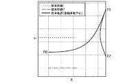
一連の駐車動作は駆動モータ1、電動油圧ブレーキ2、電動パワーステアリング3を用いて全て自動制御で行われる。駐車開始位置P2、切り返し位置P1、駐車終了位置P0では操舵角は0であり、ステアは中立の位置とする。前進と後進の開始位置から中間点まではステアを切り増しして行き、中間点で操舵角が最大となり、中間点から前進と後進の終了位置まではステアを切り戻しして行く。移動距離に対して、駐車軌跡の曲率の変化率を一定とし、駐車軌跡をクロソイド曲線とする。クロソイド曲線を用いることで、滑らかで、運転者が予期しやすい車両動作、ステア動作となり、運転者に対し自動制御に対する安心感を与えることができる。回転半径の小さい駐車軌跡とするため、前進と後進の中間点よりも手前でステアの切り増しを終了し、中間点を通過してしばらく移動するまで操舵角を固定し、その後ステアを切り戻しして行くことで、駐車軌跡にクロソイド曲線と円弧を併用することもできる。図7に、並列駐車で駐車軌跡がクロソイド曲線の場合の後輪車軸中心の駐車軌跡を示す。駐車終了位置P0における車両前後方向をX軸、車両左右方向をY軸と定義し、自車両の駐車枠に隣接する2つの駐車枠のうち、駐車開始位置P2から遠い駐車枠との境界を駐車枠線1、駐車開始位置P2に近い駐車枠との境界を駐車枠線2としている。ここで、より回転半径の小さい駐車軌跡とするため、切り返し位置での停車時のみ据え切りで操舵を行い、クロソイド曲線を用いずに円弧のみを用いてもよい。また、駐車開始位置P2、切り返し位置P1、駐車終了位置P0で操舵角を0以外としてもよい。
[Basic operation of parallel parking]
FIG. 6 is a diagram illustrating a basic vehicle operation of parallel parking according to the first embodiment.
The vehicle advances from the parking start position P2 to the return position P1, stops at the return position P1, moves backward from the return position P1 to the parking end position P0, and stops at the parking end position P0. The vehicle is steered in a direction away from the parking end position P0 during advance from the parking start position P2 to the turn-back position P1, and steered in a direction approaching the parking end position P0 during reverse travel from the turn-back position P1 to the parking end position P0. That is, when the parking end position P0 is located on the left side in the traveling direction of the host vehicle, the right steering is performed when traveling forward, and the left steering is performed when traveling backward. On the other hand, when the parking end position P0 is located on the right side in the traveling direction of the host vehicle, the left steering is performed when moving forward, and the right steering is performed when moving backward.
A series of parking operations are all performed by automatic control using the
図8は、並列駐車で駐車軌跡がクロソイド曲線の場合の移動距離と操舵角との関係を示す図である。
前進と後進では操舵角の正負が逆になるが、ここでは前進と後進の操舵角をどちらも正として表す。クロソイド曲線では曲線の長さに対して曲線の変化率は一定となるので、移動距離に対する操舵角の変化率もほぼ一定となる。操舵角δhと曲率χとの関係はステアリングギア比Nとホイールベースlを用いて、下記の式(1)で表される。
δh = Ntan-1(l・χ)≒N・l・χ …(1)
ホイールベースlと曲率χの積が小さい範囲では式(1)の近似が成り立ち、移動距離に対する曲率の変化率が一定であれば、操舵角の変化率も一定となる。
図8で後進の開始時にしばらく操舵角が0となっているが、この区間では車速制御による車速の誤差によって前進の終了時に操舵角0で移動距離が所定距離以上になった分、後進の開始時に操舵角0で前進での移動距離の超過分を逆走しているためである。これにより駐車終了位置の精度が保たれる。
FIG. 8 is a diagram illustrating the relationship between the moving distance and the steering angle when the parking locus is a clothoid curve in parallel parking.
In forward and reverse, the sign of the steering angle is reversed, but here the forward and reverse steering angles are both represented as positive. In the clothoid curve, the rate of change of the curve is constant with respect to the length of the curve, so the rate of change of the steering angle with respect to the moving distance is also substantially constant. Relationship between the steering angle [delta] h and the curvature χ by using the steering gear ratio N and the wheelbase l, represented by the following formula (1).
δh = Ntan -1 (l ・ χ) ≒ N ・ l ・ χ… (1)
In the range where the product of the wheel base l and the curvature χ is small, the approximation of Expression (1) is established, and if the change rate of the curvature with respect to the moving distance is constant, the change rate of the steering angle is also constant.
In FIG. 8, the steering angle has been 0 for a while at the start of reverse travel, but in this section, the reverse travel start is as much as the travel distance exceeds the predetermined distance at the
図9は、並列駐車で駐車軌跡がクロソイド曲線と円弧による場合の後輪車軸中心の駐車軌跡を示す図である。駐車開始位置P2で車両が駐車枠の方向を向いているので、回転半径の小さい駐車軌跡を設定する必要があり、駐車軌跡にクロソイド曲線と円弧を用いている。
図10は、並列駐車で駐車軌跡がクロソイド曲線と円弧による場合の移動距離と操舵角との関係を示す図である。前進と後進では操舵角の正負が逆になるが、ここでは前進と後進の操舵角をどちらも正として表す。移動距離に対して操舵角が変化する区間がクロソイド曲線の区間で、中間付近の操舵角が一定の区間が円弧の区間である。
FIG. 9 is a diagram showing a parking locus at the center of the rear wheel axle when the parking locus is a clothoid curve and an arc in parallel parking. Since the vehicle faces the direction of the parking frame at the parking start position P2, it is necessary to set a parking locus with a small turning radius, and a clothoid curve and an arc are used for the parking locus.
FIG. 10 is a diagram illustrating the relationship between the moving distance and the steering angle when the parking locus is a clothoid curve and an arc in parallel parking. In forward and reverse, the sign of the steering angle is reversed, but here the forward and reverse steering angles are both represented as positive. A section where the steering angle changes with respect to the movement distance is a section of a clothoid curve, and a section where the steering angle near the middle is constant is an arc section.
[駐車軌跡の設定]
次に、実施例1の駐車支援装置での並列駐車の軌跡の設定について述べる。並列駐車の軌跡の設定は図3の駐車軌跡設定部51で行われる。
図11は、並列駐車の軌跡を求める条件を示す図である。駐車開始位置P2、切り返し位置P1、駐車終了位置P0は図6と同様であり、自車両をCar1、駐車終了位置P0を含む自車両Car1の駐車枠をPA1、駐車枠PA1の左右に隣接する駐車枠をPA2、PA3、左右の駐車車両をCar2、Car3とする。駐車開始位置P2、切り返し位置P1、駐車終了位置P0は自車両Car1の後輪車軸中心の位置とする。駐車枠PA1に対し、駐車終了位置P0は自車両Car1の左右方向の中心にある。駐車終了位置P0に駐車したとき、自車両Car1の前端と駐車枠PA1の前端とが重なる位置に駐車終了位置P0を設定する。また、駐車枠PA1の前端を含む直線をL1とし、直線L1と平行で直線L1との距離がWs1となる直線をL2とする。直線L2に対して垂直で、駐車終了位置P0との距離がWs2となる直線をL3、距離がWs3となる直線をL4とする。さらに、直線L1に含まれる駐車枠PA1の境界の両端点のうち、切り返し位置P1から駐車終了位置P0の後進時に車両の内側となる点をR1、もう片方の点をR2とする。また、駐車枠PA1、PA3の境界を含む直線を直線L5とする。
制限領域設定部50aは、直線(仮想線)L1、L2、L3、L4で囲まれた領域と駐車枠PA1の内部とを合わせた領域を制限領域Area1として設定し、駐車軌跡設定部51は、制限領域Area1内において直線L1、L2、L3、L4に基づいて自車両を駐車終了位置P0に並列駐車させるための駐車軌跡を設定する。直線L2,L3,L4までの距離Ws1、Ws2、Ws3を無限大に設定し、各直線による領域の制限を無効にすることもできる。カメラ11〜14で駐車車両Car2、Car3を検知し、Area1のうち、駐車枠PA1と直線L1とによって区切られる領域を駐車車両Car2、Car3の付近まで拡大することもできる。
[Parking locus setting]
Next, the setting of the trajectory for parallel parking in the parking assist device of the first embodiment will be described. The setting of the parallel parking locus is performed by the parking
FIG. 11 is a diagram showing conditions for obtaining a parallel parking locus. The parking start position P2, the turn-back position P1, and the parking end position P0 are the same as in FIG. 6, and the own vehicle Car1 including the own vehicle Car1 including the parking end position P0 is PA1, and the parking frame adjacent to the left and right of the parking frame PA1. Frames are PA2 and PA3, and left and right parked vehicles are Car2 and Car3. The parking start position P2, the turn-back position P1, and the parking end position P0 are positions at the center of the rear axle of the host vehicle Car1. The parking end position P0 is at the center in the left-right direction of the host vehicle Car1 with respect to the parking frame PA1. When the vehicle is parked at the parking end position P0, the parking end position P0 is set at a position where the front end of the host vehicle Car1 and the front end of the parking frame PA1 overlap. A straight line including the front end of the parking frame PA1 is L1, and a straight line parallel to the straight line L1 and having a distance Ws1 from the straight line L1 is L2. A straight line perpendicular to the straight line L2 and having a distance Ws2 from the parking end position P0 is L3, and a straight line having a distance Ws3 is L4. Further, of the two end points of the boundary of the parking frame PA1 included in the straight line L1, R1 is a point that is inside the vehicle when the vehicle travels backward from the switching position P1 to the parking end position P0, and R2 is the other point. A straight line including the boundary between the parking frames PA1 and PA3 is defined as a straight line L5.
The restricted
図12、図13は、駐車軌跡を求めるフローチャートである。図6では駐車軌跡はP2→P1→P0と示されているが、切り返しが増える度に…P4→P3→P2→P1→P0というように切り返しの位置が増え、駐車開始位置の添え字の番号を最大、駐車終了位置の添え字の番号を最小の0とする。Pnは各切り返し位置での後輪車軸中心の位置とする。Pn+1→Pnの軌跡で、nが偶数の場合は車両が後進して左に操舵する軌跡を表し、nが奇数の場合は車両が前進して右に操舵する軌跡を表す。この場合の操舵の方向は駐車開始位置に対して駐車終了位置が左にある場合のものであり、駐車開始位置に対して駐車終了位置が右にある場合は操舵の方向が逆になる。また、図12、図13のフローチャートには軌跡を求めるステップS4、S7、S12、S14、S17、S19が含まれるが、詳細については後述する。
ステップS1では、切り返し回数k=1とし、R1を車両が通過するかどうかを示すフラグf_Set_R1=1とする。
ステップS2では、切り返し回数kが上限値kmax以下であればステップS3に進み、上限値kmaxよりも大きい場合はリターンに進む。
ステップS3では、切り返し回数k=1であればステップS4に進み、切り返し回数kが1以外であればステップS10に進む。
ステップS4では、P3→P2に後進する軌跡を求める。ステップS4、S19の処理は後述する図14、図15のフローチャートに従う。
ステップS5では、ステップS4の解がある場合はステップS6に進み、解がない場合はリターンに進む。
ステップS6では、計算の継続または終了を示す値kfが0の場合はステップS7に進み、kfが0以外の場合はリターンへ進む。ここで、kfが1の場合は駐車軌跡が求まって計算を終了することを示し、kfが2の場合は駐車軌跡が求まらずに計算を終了することを示す。
ステップS7(第2軌跡算出部)では、駐車軌跡設定部51の第3駐車軌跡設定部(第3駐車軌跡算出部)51cにおいて、図6のようなP2→P0の軌跡を求める。
ステップS8では、ステップS7の解がある場合はリターンに進み、解がない場合はステップS9に進む。
ステップS9では、繰り返し回数kに1を加算してステップS2に戻る。
12 and 13 are flowcharts for obtaining a parking locus. In FIG. 6, the parking locus is shown as P2 → P1 → P0. However, as the number of turnover increases, the turnover position increases as P4 → P3 → P2 → P1 → P0. Is the maximum and the subscript number at the parking end position is the
In step S1, the number of turnovers k = 1, and a flag f_Set_R1 = 1 indicating whether or not the vehicle passes through R1.
In step S2, the process proceeds to step S3 if the number of times of switching k is equal to or less than the upper limit value kmax, and proceeds to return if it is greater than the upper limit value kmax.
In step S3, if the number of turnovers k = 1, the process proceeds to step S4. If the number of turnovers k is other than 1, the process proceeds to step S10.
In step S4, a trajectory going backward from P3 to P2 is obtained. The processing in steps S4 and S19 follows the flowcharts shown in FIGS.
In step S5, if there is a solution in step S4, the process proceeds to step S6, and if there is no solution, the process proceeds to return.
In step S6, if the value kf indicating continuation or termination of the calculation is 0, the process proceeds to step S7, and if kf is other than 0, the process proceeds to return. Here, when kf is 1, it indicates that the parking locus is obtained and the calculation is terminated, and when kf is 2, the calculation is terminated without obtaining the parking locus.
In step S7 (second trajectory calculation unit), a third trajectory setting unit (third parking trajectory calculation unit) 51c of the parking
In step S8, if there is a solution in step S7, the process proceeds to return, and if there is no solution, the process proceeds to step S9.
In step S9, 1 is added to the number of repetitions k, and the process returns to step S2.
ステップS10では、それまでの軌跡の計算結果である、駐車開始位置Pmax→P2までの軌跡の各添え字の番号に2を加算し、Pmax+2→P4までの軌跡とする。この後で新たなP4→P2の軌跡を求めることで、切り返し回数を増やした駐車軌跡Pmax+2→P2が求まる。
ステップS11では、f_Set_R1=1の場合はステップS12に進み、f_Set_R1が1以外の場合はステップS16に進む。
ステップS12では、駐車軌跡設定部51の第3駐車軌跡設定部51cにおいて、R1を車両が通過するP4→P2の軌跡を求める。
ステップS13では、ステップS12の解がある場合はステップS6に進み、解がない場合はステップS14に進む。
ステップS14では、P2のY座標YP2を0として、ステップS12と同様にR1を車両が通過するP4→P2の軌跡を求める。
ステップS15では、ステップS14の解がある場合はステップS6に進み、解がない場合はステップS16に進む。
ステップS16では、f_Set_R1=0とする。ステップS12、S14で一度R1を車両が通過するP4→P2の軌跡が求まらない場合は、その後切り返しをしながら車両に搭載された操舵装置の最大操舵角、最大操舵角速度で操舵した場合でもR1を車両が通過できないということを意味する。よって、この場合はf_Set_R1=0とすることで、切り返し回数を増やして再度P4→P2の軌跡を求める場合でもステップS11の判定によってステップS12、S14の処理をスキップし、ステップS17、S19でR1を車両が通過しないP4→P2の軌跡を求める。
ステップS17では最大操舵角、最大操舵角速度で操舵するときのP4→P3の軌跡を求める。
ステップS18では、ステップS17の解がある場合はステップS19に進み、解がない場合はリターンへ進む。
ステップS19では、ステップS4と同じ処理でP3→P2の軌跡を求める。
ステップS20では、ステップS19の解がある場合はステップS6へ進み、解がない場合はリターンへ進む。
In step S10, 2 is added to each subscript number of the trajectory from the parking start position Pmax to P2, which is the calculation result of the trajectory so far, to obtain a trajectory from Pmax + 2 to P4. Thereafter, a new trajectory of P4 → P2 is obtained to obtain a parking trajectory Pmax + 2 → P2 in which the number of turnovers is increased.
In step S11, if f_Set_R1 = 1, the process proceeds to step S12. If f_Set_R1 is other than 1, the process proceeds to step S16.
In step S12, the third parking
In step S13, if there is a solution in step S12, the process proceeds to step S6, and if there is no solution, the process proceeds to step S14.
In step S14, the Y coordinate YP2 of P2 is set to 0, and the locus of P4 → P2 through which the vehicle passes R1 is obtained in the same manner as in step S12.
In step S15, if there is a solution in step S14, the process proceeds to step S6, and if there is no solution, the process proceeds to step S16.
In step S16, f_Set_R1 = 0. If the path of P4 → P2 through which the vehicle passes R1 once in steps S12 and S14 cannot be obtained, even if steering is performed at the maximum steering angle and the maximum steering angular speed of the steering device mounted on the vehicle after turning back It means that the vehicle cannot pass through R1. Therefore, in this case, by setting f_Set_R1 = 0, even when the trajectory of P4 → P2 is obtained again by increasing the number of times of switching, the processing of steps S12 and S14 is skipped by the determination of step S11, and R1 is set in steps S17 and S19. The trajectory of P4 → P2 where the vehicle does not pass is obtained.
In step S17, the locus of P4 → P3 when steering at the maximum steering angle and the maximum steering angular velocity is obtained.
In step S18, if there is a solution in step S17, the process proceeds to step S19, and if there is no solution, the process proceeds to return.
In step S19, the trajectory of P3 → P2 is obtained by the same process as step S4.
In step S20, if there is a solution in step S19, the process proceeds to step S6, and if there is no solution, the process proceeds to return.
次に、図14、図15のフローチャートを用い、図12、図13のステップS4、S19のP3→P2で後進する軌跡を求める手順を説明する。
ステップS30では、図16に示すように最大操舵角、最大操舵角速度で駐車終了位置P0となるまで後進した場合の軌跡P3→P2を求める。図16では、図11のArea1と、車両の前後左右端、後輪車軸中心、後輪車軸左右端の軌跡が示されている。車両の前輪のみを操舵する場合、車両の旋回中心は後輪車軸の延長線上にあるので、車両が旋回するとき、車両の前後左右端が車両の最も外側の軌跡を描き、後輪車軸左右端が車両の最も内側の軌跡を描く。したがって、車両の前後左右端と後輪車軸左右端の軌跡が共にArea1の内部にあれば、車両全部の軌跡がArea1に収まることになる。
ステップS31では、ステップS30の解がある場合はステップS32に進み、解がない場合は処理を終了する。
ステップS32では、P3→P2でR1の外側を通るか判定し、外側を通る場合はステップS33に進み、外側を通らない場合はステップS43に進む。図16の例では、R1の外側を通るのでステップS33に進む。XY座標軸(駐車終了位置P0における車両前後方向をX軸、車両左右方向をY軸)と座標原点0を図16のように定義し、座標原点0を駐車終了位置P0とする。
ステップS33(第1軌跡算出部)では、図16のようにP2のY座標YP2≧0の場合はステップS34に進み、0よりも小さい場合はステップS37に進む。
ステップS34では、P3をP1とし、図17のようにP1→P0の軌跡を求める。このとき、P0の位置は元々の駐車終了位置からX軸上を正の側に移動した任意の点とし、P0の移動量をdsとする。ds>0のときは、駐車開始位置PmaxからP0まで切り返しを繰り返した後、dsだけ直進で後進すれば元々の駐車終了位置に到達する。
ステップS35では、ステップS34の解がある場合はステップS36に進み、解がない場合は処理を終了する。
Next, a procedure for obtaining a backward trajectory from P3 → P2 in steps S4 and S19 of FIGS. 12 and 13 will be described using the flowcharts of FIGS.
In step S30, as shown in FIG. 16, the trajectory P3 → P2 is calculated when the vehicle travels backward to the parking end position P0 with the maximum steering angle and the maximum steering angular velocity. FIG. 16 shows Area1 of FIG. 11 and the trajectories of the front and rear left and right ends, the rear wheel axle center, and the rear wheel axle left and right ends of the vehicle. When steering only the front wheels of the vehicle, the turning center of the vehicle is on the extension line of the rear axle, so when the vehicle turns, the front and rear left and right ends of the vehicle draw the outermost trajectory of the vehicle, and the rear wheel axle left and right ends Draws the innermost track of the vehicle. Therefore, if the front and rear left and right ends of the vehicle and the left and right ends of the rear axle are both within Area1, the entire vehicle will be within Area1.
In step S31, if there is a solution in step S30, the process proceeds to step S32. If there is no solution, the process ends.
In step S32, it is determined whether P3 → P2 passes the outside of R1, and if the outside passes, the process proceeds to step S33, and if not, the process proceeds to step S43. In the example of FIG. 16, since it passes outside R1, the process proceeds to step S33. The XY coordinate axis (the vehicle front-rear direction at the parking end position P0 is the X axis and the vehicle left-right direction is the Y axis) and the coordinate
In step S33 (first trajectory calculation unit), as shown in FIG. 16, if the Y coordinate YP2 ≧ 0 of P2, the process proceeds to step S34, and if smaller than 0, the process proceeds to step S37.
In step S34, P3 is set to P1, and the locus of P1 → P0 is obtained as shown in FIG. At this time, the position of P0 is an arbitrary point moved from the original parking end position on the X axis to the positive side, and the movement amount of P0 is ds. When ds> 0, after repeating the return from the parking start position Pmax to P0, the vehicle reaches the original parking end position by going straight forward by ds.
In step S35, if there is a solution in step S34, the process proceeds to step S36, and if there is no solution, the process ends.
ステップS36では、Pmax→P3の軌跡をPmax-2→P1に移動し、駐車開始位置から駐車終了位置までの駐車軌跡が求まっているので、kf=1とする。
ステップS37では、YP2≧-Wpの場合はステップS38に進み、YP2<-Wpの場合はステップS39に進む。Wpは図11で車両Car1が左右方向で駐車枠PA1の中心に停車した場合の、車両左右面から駐車枠PA1までの距離である。
ステップS38では、駐車軌跡設定部51の第2駐車軌跡設定部(第2駐車軌跡算出部)51bにおいて、後進しながらYP2=0となった位置をP2として、最大操舵角、最大操舵角速度で後進するときのP3→P2の軌跡を求める。図18は0>YP2≧-Wpの例であり、この場合は駐車終了位置P0と平行になったときに横位置(Y軸方向の位置)がずれてしまう。この位置まで後進すると、その後幅寄せをして駐車終了位置P0に到達することになるので、切り返し回数が増え、移動距離が長くなってしまう。そこで、後進しながらYP2=0となった位置をP2としてP3→P2の軌跡を求める。図19は求めた軌跡の例である。
ステップS39では、駐車軌跡設定部51の第1駐車軌跡設定部(第1駐車軌跡算出部)51aにおいて、最大操舵角、最大操舵角速度で後進するときの軌跡P3→P2を求める。図20はYP2<-Wpの例であり、この場合は最大操舵角、最大操舵角速度で後進するときの軌跡P3→P2を求める。軌跡を求めた結果を図21に示す。図21では、P2で車両右後端が図11の直線L5に接している。図22もYP2<-Wpの例であるが、最大操舵角、最大操舵角速度で後進するときの軌跡P3→P2を求めると図23のようにP2で車両後端面がR2に接する。図24もYP2<-Wpの例であるが、最大操舵角、最大操舵角速度で後進するときの軌跡P3→P2を求めると図25のようにP2で車両左後端が図11の直線L1に接する。図26もYP2<-Wpの例であるが、最大操舵角、最大操舵角速度で後進するときの軌跡P3→P2を求めると図27のようにP2で車両右後端が図11の直線L4に接する。
ステップS40では、ステップS39の解がない場合は処理を終了し、解がある場合はステップS41に進む。
ステップS41では、ステップS39で求めたP2のY座標YP2とあらかじめ設定したYP2の下限値YP2minとを比較し、YP2<YP2minの場合はステップS42に進み、YP2≧YP2minの場合は処理を終了する。
ステップS42では、P3→P2の軌跡を消去する。図28はYP2<-Wpの例であり、ステップS39で最大操舵角、最大操舵角速度で後進するときの軌跡P3→P2を求めると、図25と同様に、図29のようにP2で車両左後端が図11の直線L1に接する。ただし、図25ではYP2≧YP2minであるが、図29ではYP2<YP2minであるため、P3→P2は消去され、P3から後進せずに前進する軌跡が作られる。駐車終了位置P0に少ない切り返し回数、短い移動距離で駐車するためには、切り返しを繰り返しながら車両後部が駐車枠PA1の入口に近付いて行く必要があるため、図29のようなP3→P2の軌跡が作られた場合は後進を前進に修正する。
In step S36, the trajectory of Pmax → P3 is moved from Pmax-2 → P1, and the parking trajectory from the parking start position to the parking end position is obtained, so kf = 1 is set.
In step S37, if YP2 ≧ −Wp, the process proceeds to step S38, and if YP2 <−Wp, the process proceeds to step S39. Wp is the distance from the vehicle left-right surface to the parking frame PA1 when the vehicle Car1 stops in the center of the parking frame PA1 in the left-right direction in FIG.
In step S38, in the second parking locus setting unit (second parking locus calculating unit) 51b of the parking
In step S39, the first parking locus setting unit (first parking locus calculating unit) 51a of the parking
In step S40, if there is no solution in step S39, the process is terminated, and if there is a solution, the process proceeds to step S41.
In step S41, the Y coordinate YP2 of P2 obtained in step S39 is compared with the preset lower limit YP2min of YP2, and if YP2 <YP2min, the process proceeds to step S42, and if YP2 ≧ YP2min, the process is terminated.
In step S42, the locus P3 → P2 is deleted. FIG. 28 shows an example of YP2 <−Wp. When the trajectory P3 → P2 for reverse traveling at the maximum steering angle and maximum steering angular velocity is obtained in step S39, the vehicle left at P2 as shown in FIG. 29 as in FIG. The rear end is in contact with the straight line L1 in FIG. However, although YP2 ≧ YP2min in FIG. 25, since YP2 <YP2min in FIG. 29, P3 → P2 is deleted, and a trajectory that moves forward without moving backward from P3 is created. In order to park at the parking end position P0 with a small number of turnovers and a short moving distance, the rear of the vehicle needs to approach the entrance of the parking frame PA1 while repeating the turnover, so the locus of P3 → P2 as shown in FIG. If is made, reverse is corrected to forward.
ステップS43では、ステップS30で求めたP3→P2の軌跡が図30のようにR1の内側を通る場合、ステップS30のように最大操舵角、最大操舵角速度ではなく、R1を通過して駐車終了位置P0と平行になるまで後進した場合のP3→P2の軌跡を図31のように求める。
ステップS44では、ステップS43の解がある場合はステップS45に進み、解がない場合は処理を終了する。
ステップS45では、ステップS43で求めたP2のY座標YP2≧0の場合はステップS46に進み、YP2<0の場合はステップS49に進む。図31はYP2≧0の例である。
ステップS46(第1軌跡算出部)では、ステップS34と同様にP3をP1とし、図32のようにP1→P0の軌跡を求める。P0の位置は元々の駐車終了位置からX軸上を正の側に移動した任意の点とし、P0の移動量をdsとする。
ステップS47では、ステップS46の解がある場合はステップS48に進み、解がない場合は処理を終了する。
ステップS48では、ステップS36と同様にPmax→P3の軌跡をPmax-2→P1に移動し、駐車開始位置から駐車終了位置までの駐車軌跡が求まっているので、kf=1とする。
ステップS49の判定でYP2≧-Wpの場合はステップS50に進み、YP2<-Wpの場合はステップS51に進む。
ステップS50では、第2駐車軌跡設定部51bにおいて、YP2=0となった位置をP2とし、R1を通って後進するときの軌跡P3→P2を求める。図33は、図30と同様にステップS30で求めたP3→P2の軌跡がR1の内側を通る例であるが、このときステップS43でR1を通過して駐車終了位置P0と平行になるまで後進した場合のP3→P2の軌跡を求めると、図34のようになる。図34では0>YP2≧-Wpとなり、この場合は駐車終了位置と平行になったときに横位置(Y軸方向の位置)がずれてしまう。この位置まで後進すると、その後幅寄せをして駐車終了位置に到達することになるので、切り返し回数が増え、移動距離が長くなってしまう。そこで、ステップS38と同様に、後進しながらYP2=0となった位置をP2としてP3→P2の軌跡を求める。図35は求めた軌跡の例である。
ステップS51では、第1駐車軌跡設定部51aにおいて、R1を通って後進するときのP3→P2の軌跡を求める。図36も図30、図33と同様にステップS30で求めたP3→P2の軌跡がR1の内側を通る例であるが、このときステップS43でR1を通過して駐車終了位置P0と平行になるまで後進した場合のP3→P2の軌跡を求めると図37のようになる。図37ではYP2<-Wpとなるため、R1を通過するP3→P2の軌跡を求める。軌跡を求めた結果が図38である。図38ではP2で車両右後端が図11の直線L5に接している。図39も図30、図33、図36と同様にステップS30で求めたP3→P2の軌跡がR1の内側を通る例であるが、このときステップS43でR1を通過して駐車終了位置P0と平行になるまで後進した場合のP3→P2の軌跡を求めると図40のようになる。図40ではYP2<-Wpとなり、ステップS51でR1を通過するP3→P2の軌跡を求める。軌跡を求めた結果が図41である。図41では、P2で車両後端縁がR2に接している。
以上が図14、図15のフローチャートに従い、図12、図13のステップS4、S19でP3→P2の軌跡を求める手順である。
In step S43, when the path of P3 → P2 obtained in step S30 passes through the inside of R1 as shown in FIG. 30, the parking end position passes through R1 instead of the maximum steering angle and the maximum steering angular velocity as in step S30. The trajectory of P3 → P2 when the vehicle travels backward until it becomes parallel to P0 is obtained as shown in FIG.
In step S44, if there is a solution in step S43, the process proceeds to step S45, and if there is no solution, the process ends.
In step S45, if the Y coordinate YP2 ≧ 0 of P2 obtained in step S43, the process proceeds to step S46, and if YP2 <0, the process proceeds to step S49. FIG. 31 is an example of YP2 ≧ 0.
In step S46 (first trajectory calculation unit), P3 is set to P1 as in step S34, and a trajectory of P1 → P0 is obtained as shown in FIG. The position of P0 is an arbitrary point moved to the positive side on the X axis from the original parking end position, and the movement amount of P0 is ds.
In step S47, if there is a solution in step S46, the process proceeds to step S48, and if there is no solution, the process ends.
In step S48, the locus of Pmax → P3 is moved from Pmax-2 to P1 in the same manner as in step S36, and the parking locus from the parking start position to the parking end position is obtained. Therefore, kf = 1 is set.
If it is determined in step S49 that YP2 ≧ −Wp, the process proceeds to step S50, and if YP2 <−Wp, the process proceeds to step S51.
In step S50, in the second parking locus setting unit 51b, the position where YP2 = 0 is set as P2, and the locus P3 → P2 when traveling backward through R1 is obtained. FIG. 33 is an example in which the locus of P3 → P2 obtained in step S30 passes through the inside of R1 as in FIG. 30. At this time, the vehicle travels backward until it passes through R1 and becomes parallel to the parking end position P0 in step S43. When the locus of P3 → P2 in this case is obtained, it is as shown in FIG. In FIG. 34, 0> YP2 ≧ −Wp, and in this case, the horizontal position (position in the Y-axis direction) is shifted when parallel to the parking end position. If the vehicle moves backward to this position, the vehicle will then be adjusted to reach the parking end position, increasing the number of times of turning back and increasing the moving distance. Therefore, similarly to step S38, the position of YP2 = 0 while moving backward is set as P2, and the locus of P3 → P2 is obtained. FIG. 35 is an example of the obtained trajectory.
In step S51, the first parking locus setting unit 51a obtains a locus of P3 → P2 when going backward through R1. FIG. 36 is also an example in which the locus of P3 → P2 obtained in step S30 passes through the inside of R1 as in FIGS. 30 and 33. At this time, it passes through R1 and becomes parallel to the parking end position P0 in step S43. FIG. 37 shows the locus of P3 → P2 when the vehicle travels backward. In FIG. 37, since YP2 <−Wp, the locus of P3 → P2 passing through R1 is obtained. The result of obtaining the locus is shown in FIG. In FIG. 38, the right rear end of the vehicle is in contact with the straight line L5 in FIG. 11 at P2. 39 is also an example in which the locus of P3 → P2 obtained in step S30 passes through the inside of R1 as in FIGS. 30, 33, and 36. At this time, it passes through R1 in step S43 and the parking end position P0. FIG. 40 shows the locus of P3 → P2 when the vehicle travels backward until it becomes parallel. In FIG. 40, YP2 <−Wp, and the locus of P3 → P2 passing through R1 is obtained in step S51. The result of obtaining the locus is shown in FIG. In FIG. 41, the rear edge of the vehicle is in contact with R2 at P2.
The above is the procedure for obtaining the locus of P3 → P2 in steps S4 and S19 of FIGS. 12 and 13 according to the flowcharts of FIGS.
次に、図12のフローチャートのステップS7でP2→P0の軌跡を求める手順について、図42のフローチャートを用いて説明する。図14、図15のステップS34、S46、図17、図32と同様に、P0の位置は元々の駐車終了位置からX軸上を正の側に移動した任意の点とし、P0の移動量をdsとする。ds>0のときは、駐車開始位置PmaxからP0まで切り返しを繰り返した後、dsだけ直進で後進すれば駐車終了位置に到達する。
ステップS60では、P2→P1、P1→P0の両方で最大操舵角、最大操舵角速度で操舵した場合の軌跡を求める。図43は求めた軌跡の例である。
ステップS61では、ステップS60の解がある場合はステップS62に進み、解がない場合はステップS64に進む。
ステップS62では、ステップS60で求めた軌跡のP1で車両がArea1の内部にある場合はステップS63に進み、Area1からはみ出す場合はステップS64に進む。
ステップS63では、P1→P0で車両がR1の外側を通過するときは求めた軌跡をP2→P0の解として処理を終了し、R1の内側を通過するときはステップS64に進む。図43の例では、P1で車両がArea1の内部にあり、P1→P0で車両がR1の外側を通過するため、求めた軌跡がP2→P0の解となる。
ステップS64では、P1→P0では最大操舵角、最大操舵角速度で操舵し、P1で車両端部がArea1の境界に接するP2→P0の軌跡を求める。図44は求めた軌跡の例であり、P1で車両右前端が図11の直線L2に接している。
ステップS65では、ステップS64の解がある場合はステップS66に進み、解がない場合は処理を終了する。
ステップS66では、ステップS64で求めた軌跡のP1で車両がArea1の内部にある場合はステップS67に進み、Area1からはみ出す場合はP2→P0の軌跡の解がないとして処理を終了する。
ステップS67では、P1→P0で車両がR1の外側を通過するときは求めた軌跡をP2→P0の解として処理を終了し、R1の内側を通過するときはP2→P0の解がないとして処理を終了する。
Next, the procedure for obtaining the locus of P2 → P0 in step S7 of the flowchart of FIG. 12 will be described using the flowchart of FIG. As in steps S34, S46, FIG. 17 and FIG. 32 in FIGS. 14 and 15, the position of P0 is an arbitrary point moved from the original parking end position to the positive side on the X axis, and the amount of movement of P0 is set as follows. ds. When ds> 0, after repeating the return from the parking start position Pmax to P0, the vehicle reaches the parking end position by going straight forward by ds.
In step S60, a trajectory is obtained when steering is performed at the maximum steering angle and the maximum steering angular velocity in both P2 → P1 and P1 → P0. FIG. 43 is an example of the obtained trajectory.
In step S61, if there is a solution in step S60, the process proceeds to step S62, and if there is no solution, the process proceeds to step S64.
In step S62, if the vehicle is inside Area1 at P1 of the trajectory obtained in step S60, the process proceeds to step S63, and if it is out of Area1, the process proceeds to step S64.
In step S63, when P1 → P0 and the vehicle passes the outside of R1, the process ends with the obtained locus as the solution of P2 → P0, and when the vehicle passes the inside of R1, the process proceeds to step S64. In the example of FIG. 43, the vehicle is inside Area1 at P1, and the vehicle passes the outside of R1 at P1 → P0, so the obtained locus is the solution of P2 → P0.
In step S64, the steering is performed at the maximum steering angle and the maximum steering angular velocity from P1 to P0, and the trajectory from P2 to P0 where the vehicle end is in contact with the boundary of Area1 is obtained at P1. FIG. 44 shows an example of the obtained trajectory. At P1, the right front end of the vehicle is in contact with the straight line L2 in FIG.
In step S65, if there is a solution in step S64, the process proceeds to step S66, and if there is no solution, the process ends.
In step S66, if the vehicle is inside Area1 at P1 of the trajectory obtained in step S64, the process proceeds to step S67, and if it is out of Area1, the process is terminated assuming that there is no solution of the trajectory of P2 → P0.
In step S67, when the vehicle passes outside R1 with P1 → P0, the process ends with the obtained trajectory as a solution of P2 → P0, and when passing inside R1, it is determined that there is no solution of P2 → P0. Exit.
次に、図13のフローチャートのステップS12でR1を通過するP4→P2の軌跡を求める処理について説明する。図45は求めた軌跡の例であり、P4→P3とP3→P2の両方で最大操舵角、最大操舵角速度で操舵する軌跡になっており、P2で車両右後端が図11の直線L5に接している。図46も求めた軌跡の例であり、P4→P3とP3→P2の両方で最大操舵角、最大操舵角速度で操舵する軌跡になっており、P2で車両後端面がR2に接している。図47も求めた軌跡の例であり、P3→P2で最大操舵角、最大操舵角速度で操舵し、P3で車両右前端が図11の直線L2に接し、P2で車両右後端が図11の直線L5に接している。図48も求めた軌跡の例であり、P3→P2で最大操舵角、最大操舵角速度で操舵し、P3で車両右前端が図11の直線L2に接し、P2で車両後端面がR2に接している。ステップS12でR1を通過するP4→P2の軌跡を求めた後、ステップS13で解があるかどうかの判定を行うが、この判定には軌跡が図11のArea1の内部に収まるかどうかの判定も含まれる。
次に、図13のフローチャートのステップS14でP2のY座標YP2=0とし、R1を通過するP4→P2の軌跡を求める処理について説明する。図49は、求めた軌跡の例である。図49のP2からさらに後進すると、駐車終了位置と平行になったときに横位置がずれてしまう。この位置まで後進すると、その後幅寄せをして駐車終了位置に到達することになるので、切り返し回数が増え、移動距離が長くなってしまう。そこで、ステップS12では、第1駐車軌跡設定部51aにより、P2において図11の直線L1、L4、L5のいずれかに車両が接する解を求め、そのような解がない場合は、ステップS14へ進み、第2駐車軌跡設定部51bにより、P2のY座標YP2=0として切り返し位置を決め、解を求める。ステップS14でもステップS12と同様に、P4→P3とP3→P2の両方で最大操舵角、最大操舵角速度で操舵する条件と、P3→P2で最大操舵角、最大操舵角速度で操舵し、P3で車両右前端が図11の直線L2に接する条件の両方で軌跡を求める。
Next, the process for obtaining the locus of P4 → P2 passing through R1 in step S12 of the flowchart of FIG. 13 will be described. FIG. 45 is an example of the obtained trajectory. The trajectory is steered at the maximum steering angle and the maximum steering angular velocity in both P4 → P3 and P3 → P2, and the right rear end of the vehicle is a straight line L5 in FIG. 11 at P2. Touching. FIG. 46 is also an example of the obtained trajectory. The trajectory is steered at the maximum steering angle and the maximum steering angular velocity in both P4 → P3 and P3 → P2, and the rear end face of the vehicle is in contact with R2 at P2. FIG. 47 is also an example of the obtained trajectory. Steering is performed at the maximum steering angle and the maximum steering angular speed from P3 → P2, the right front end of the vehicle is in contact with the straight line L2 in FIG. It is in contact with the straight line L5. FIG. 48 is also an example of the obtained trajectory. Steering is performed at the maximum steering angle and the maximum steering angular velocity from P3 → P2, the right front end of the vehicle is in contact with the straight line L2 in FIG. 11 at P3, and the rear end surface of the vehicle is in contact with R2 at P2. Yes. After obtaining the locus of P4 → P2 passing through R1 in step S12, it is determined whether or not there is a solution in step S13. This determination also includes determining whether or not the locus is within Area1 in FIG. included.
Next, the process of obtaining the locus of P4 → P2 passing through R1 with the Y coordinate YP2 = 0 of P2 in step S14 in the flowchart of FIG. 13 will be described. FIG. 49 is an example of the obtained trajectory. If the vehicle further moves backward from P2 in FIG. 49, the lateral position shifts when parallel to the parking end position. If the vehicle moves backward to this position, the vehicle will then be adjusted to reach the parking end position, increasing the number of times of turning back and increasing the moving distance. Therefore, in step S12, the first parking locus setting unit 51a obtains a solution in which the vehicle contacts one of the straight lines L1, L4, and L5 in FIG. 11 in P2, and if there is no such solution, the process proceeds to step S14. The second parking locus setting unit 51b determines the return position by setting the Y coordinate YP2 = 0 of P2 and obtains a solution. In step S14, as in step S12, the vehicle is steered at the maximum steering angle and the maximum steering angular velocity in both P4 → P3 and P3 → P2, and the vehicle is steered at the maximum steering angle and the maximum steering angular velocity from P3 → P2. The trajectory is obtained under both conditions where the right front end is in contact with the straight line L2 in FIG.
次に、図13のフローチャートのステップS17で最大操舵角、最大操舵角速度でP4→P3の軌跡を求める処理について説明する。図50は求めた軌跡の例である。P4→P3で最大操舵角、最大操舵角速度で操舵し、P3で車両左前端が図11の直線L3に接する軌跡となっている。ステップS17で図50の軌跡を求めた後、ステップS19で図14、図15のフローチャートに従い、ステップS30でP3から最大操舵角、最大操舵角速度で駐車終了位置P0と平行になるまで後進した場合の軌跡P3→P2を求めた結果が図51であり、ステップS39でP3→P2の軌跡を求めた結果が図52である。図52では、P2で車両後端面がR2に接している。このようにP4→P3とP3→P2との両方で最大操舵角、最大操舵角速度で操舵した軌跡でもR1の外側を通り、R1を通過することができないので、ステップS12、S14では解が求まらない。このようなときはステップS17、S19の処理で最大操舵角、最大操舵角速度で操舵したP4→P2の軌跡を求める。また、図53もステップS17で最大操舵角、最大操舵角速度でP4→P3の軌跡を求めた例である。図53ではP3で車両右前端が図11の直線L2に接する軌跡となっている。この後ステップS19で図14、図15のフローチャートに従い、ステップS30でP3から最大操舵角、最大操舵角速度で駐車終了位置P0と平行になるまで後進した場合の軌跡P3→P2を求めた結果が図54であり、ステップS39でP3→P2の軌跡を求めた結果が図55である。図55では、P2で車両後端面がR2に接している。 Next, the processing for obtaining the locus of P4 → P3 with the maximum steering angle and the maximum steering angular velocity in step S17 of the flowchart of FIG. 13 will be described. FIG. 50 is an example of the obtained trajectory. Steering is performed at the maximum steering angle and the maximum steering angular speed from P4 to P3, and at P3, the left front end of the vehicle is a locus in contact with the straight line L3 in FIG. 50 after obtaining the locus of FIG. 50 in step S17, in accordance with the flowcharts of FIG. 14 and FIG. 15 in step S19, in step S30 from the P3 to the maximum steering angle and the maximum steering angular velocity until the vehicle is parallel to the parking end position P0. FIG. 51 shows the result of obtaining the locus P3 → P2, and FIG. 52 shows the result of obtaining the locus P3 → P2 in step S39. In FIG. 52, the rear end surface of the vehicle is in contact with R2 at P2. In this way, even if the trajectory is steered at the maximum steering angle and the maximum steering angular velocity in both P4 → P3 and P3 → P2, it cannot pass through R1 and pass through R1, so a solution is obtained in steps S12 and S14. Not. In such a case, the trajectory of P4 → P2 steered at the maximum steering angle and the maximum steering angular velocity is obtained in the processes of steps S17 and S19. FIG. 53 is also an example in which the locus of P4 → P3 is obtained at step S17 with the maximum steering angle and the maximum steering angular velocity. In FIG. 53, the right front end of the vehicle at P3 is a locus in contact with the straight line L2 in FIG. After this, in step S19, according to the flowcharts of FIG. 14 and FIG. 15, the result of obtaining the trajectory P3 → P2 when the vehicle travels backward from P3 until it becomes parallel to the parking end position P0 from P3 in step S30. FIG. 55 shows the result of obtaining the locus of P3 → P2 in step S39. In FIG. 55, the rear end surface of the vehicle is in contact with R2 at P2.
次に、作用を説明する。
従来の駐車軌跡算出装置では、並列駐車の前進中に車両の左右の障害物の位置を検出し、後進時には駐車終了位置の左右に隣接する車両と、駐車終了位置の逆側にある障害物に接触しないように駐車軌跡を設定している。
ところが、上記従来技術では、以下の問題点を有している。
1.最初に運転者が車両を前進移動させ、その後の後進からの駐車軌跡を求めているため、最初に前進する駐車軌跡に対応しておらず、駐車開始位置が限定されてしまう。
2.最初の後進時に、隣接する駐車枠のうち車両後方側の駐車枠との境界線よりも後方側で切り返す場合に対応していない。
3.最初に後進した後に、切り返しを繰り返す場合の駐車軌跡の作成方法が明示されていない。
4.駐車終了位置P0と平行になるまで切り返しを繰り返した後に、横位置がずれている場合には幅寄せを行うため、切り返し回数が増え、移動距離が長くなる。
これに対し、実施例1では、駐車軌跡設定部51において、まず、駐車開始位置P2から1回の後進で駐車終了位置P0に移動する軌跡(第1駐車軌跡)P1→P0を算出し(ステップS34、ステップS46)、P1→P0が算出できない場合は、前進した後に後進する駐車軌跡(第2駐車軌跡)P2→P0を算出し(ステップS7)、駐車軌跡P2→P0が算出できない場合は逐次切り返し回数を増やす。これにより、最初に前進する駐車軌跡に対応できるため、任意の駐車開始位置P2から駐車軌跡を算出できる。また、駐車開始位置P2から1回の後進のみで駐車終了位置P0まで移動する軌跡P1→P0が算出できる場合にはこれを採用することで、不要な前後進によって切り返し回数が増え、移動距離が長くなるのを抑制できる。
Next, the operation will be described.
In the conventional parking locus calculation device, the positions of the left and right obstacles of the vehicle are detected while the parallel parking is moving forward, and the vehicle adjacent to the left and right of the parking end position and the obstacle on the opposite side of the parking end position when moving backward. The parking locus is set so as not to touch.
However, the above prior art has the following problems.
1. Since the driver first moves the vehicle forward and obtains the parking locus from the subsequent reverse, it does not correspond to the parking locus that moves forward first, and the parking start position is limited.
2. It does not correspond to the case of turning back on the rear side of the boundary line with the parking frame on the vehicle rear side among the adjacent parking frames at the time of the first reverse.
3. The method of creating the parking locus when repeating the turn after the first reverse is not specified.
4. After repeating the turning until the parking end position P0 becomes parallel, if the lateral position is shifted, the width is shifted, so the number of times of turning is increased and the moving distance becomes longer.
On the other hand, in the first embodiment, the parking
駐車軌跡設定部51は、前進後に後進する駐車軌跡P3→P2を求めた際、後進後のY軸方向の車両位置YP2が下限値YP2minよりも小さい場合には、P3から前進する駐車軌跡に切り替える(ステップS42)。駐車終了位置P0に少ない切り返し回数、短い移動距離で駐車するためには、切り返しを繰り返しながら車両後部が駐車枠PA1の入口に近付いて行く必要がある。よって、車両後部が駐車枠PA1の入口から遠ざかる駐車軌跡P3→P2が算出された場合には、この駐車軌跡を採用せずにP3から前進する駐車軌跡を算出することで、少ない切り返し回数、短い移動距離の駐車軌跡を求めることができる。
駐車軌跡設定部51は、自車両の駐車枠PA1と、障害物などで制限された領域(直線L1、L2、L3、L4で囲まれた領域)とを合わせた制限領域Area1(図11)内で自車両を駐車終了位置P0に並列駐車させるための駐車軌跡を求める。制限領域Area1をT字型に設定したことで、自車両の移動可能範囲を最大限利用し、前進した後に後進する駐車軌跡を算出できる。よって、任意の駐車開始位置P2から少ない切り返し回数、短い移動距離の駐車軌跡を算出できる。
When the parking
The parking
駐車軌跡設定部51は、P3からP0と平行になるまで後進したときのP2のY座標YP2が-Wpよりも小さい場合、すなわち、P2と駐車終了位置P0とのY軸方向の距離が、自車両を駐車枠PA1の中心に停車させたときの車両右面(駐車スペースが自車の進行方向左側の場合)から駐車枠PA1までの距離Wpよりも大きい場合には、制限領域Area1を囲む各仮想線L1、L4、L5に自車両が接触する点を切り返し点としてP3→P2の軌跡を算出する(ステップS39、ステップS51)。各仮想線L1、L4、L5を切り返し点として駐車軌跡を算出することで、制限領域Area1を最大限に活用して少ない切り返し回数、短い移動距離の駐車軌跡を算出できる。
一方、P3からP0と平行になるまで後進したときのP2のY座標YP2が-Wp以上の場合、すなわち、P2と駐車終了位置P0とのY軸方向の距離が、自車両を駐車枠PA1の中心に停車させたときの車両右面から駐車枠PA1までの距離Wpよりも小さい場合には、YP2=0となった位置(Y座標が駐車終了位置P0のY座標と一致した位置)をP2としてP3→P2の軌跡を算出する(ステップS38、ステップS50)。YP2≧-Wpの場合、自車両が駐車終了位置P0と平行となったときにY軸方向の位置がずれてしまい、この位置まで後進すると、その後幅寄せをして駐車終了位置P0に到達することとなる。幅寄せを行うと切り返し回数が増え、移動距離も長くなってしまう。そこで、YP2≧-Wpの場合はYP=0となった位置をP2としてP3→P2の軌跡を求めることで、少ない切り返し回数、短い移動距離の駐車軌跡を算出できる。
If the Y coordinate YP2 of P2 when moving backward from P3 to parallel to P0 is smaller than -Wp, that is, the distance in the Y-axis direction between P2 and the parking end position P0 When the vehicle stops at the center of the parking frame PA1, if the distance from the right side of the vehicle (when the parking space is on the left side in the direction of travel of the host vehicle) to the parking frame PA1 is greater than the distance Wp, each virtual surrounding the restricted area Area1 The trajectory of P3 → P2 is calculated using the points where the host vehicle contacts the lines L1, L4, and L5 as turning points (steps S39 and S51). By calculating the parking locus using the virtual lines L1, L4, and L5 as turning points, it is possible to calculate a parking locus with a small number of turning times and a short movement distance by making the maximum use of the restricted area Area1.
On the other hand, if the Y coordinate YP2 of P2 when moving backward from P3 to parallel to P0 is greater than -Wp, that is, the distance in the Y-axis direction between P2 and the parking end position P0 If it is smaller than the distance Wp from the right side of the vehicle to the parking frame PA1 when stopped at the center, the position where YP2 = 0 (the position where the Y coordinate matches the Y coordinate of the parking end position P0) is set as P2. The trajectory of P3 → P2 is calculated (step S38, step S50). When YP2 ≧ -Wp, the position in the Y-axis direction shifts when the host vehicle is parallel to the parking end position P0, and when moving backward to this position, the vehicle is further shifted to reach the parking end position P0. It will be. If width adjustment is performed, the number of times of turn-back increases and the moving distance becomes longer. Therefore, when YP2 ≧ −Wp, the trajectory of P3 → P2 is obtained by setting the position where YP = 0 as P2, and a parking trajectory with a small number of times of return and a short moving distance can be calculated.
駐車軌跡設定部51は、軌跡として円弧を用いる場合は最大操舵角を用い、軌跡としてクロソイド曲線を用いる場合は最大操舵角、最大操舵角速度を用いて駐車軌跡を算出する(ステップS17、ステップS38、ステップS39、ステップS60)。最大操舵角、最大操舵角速度を用いることで、最短の駐車軌跡を算出できる。
駐車軌跡設定部51は、駐車軌跡を算出する際、最大操舵角、最大操舵角速度という条件と、制限領域Area1を囲む各仮想線L1、L2、L3、L4に接したときに切り返しを行うという条件とのどちらか一方しか選択できない場合、最大操舵角、最大操舵角速度という条件を優先する(ステップS60、ステップS64)。駐車軌跡は、最大操舵角、最大操舵角速度を用いて算出したとき最短となるため、最短の駐車軌跡を算出できる。
なお、少ない操舵量の後進のみで駐車終了位置P0に到達できる場合には、最大操舵角、最大操舵角速度で駐車軌跡を算出する必要はなく、この場合に最大操舵角、最大操舵角速度で駐車軌跡を求めると、駐車終了位置P0に到達できず、切り返し回数が増えるおそれがある。よって、この場合は最大操舵角、最大操舵角速度以下で駐車軌跡を算出する(ステップS34、ステップS46)。
また、後進時に最大操舵角、最大操舵角速度を用いると自車両が点R1の内側を通過する場合も、最大操舵角、最大操舵角速度以下で駐車軌跡を算出する(ステップS50、ステップS51)。
さらに、前進時に最大操舵角、最大操舵角速度を用いると仮想線L2から制限領域Area1の外側にはみ出す場合も、最大操舵角、最大操舵角速度以下で駐車軌跡を算出する(ステップS12、ステップS14、ステップS64)。
The parking
When the parking locus is calculated, the parking
If the parking end position P0 can be reached with only a small amount of reverse steering, it is not necessary to calculate the parking locus with the maximum steering angle and the maximum steering angular velocity. In this case, the parking locus is with the maximum steering angle and the maximum steering angular velocity. , The parking end position P0 cannot be reached, and the number of times of switching may increase. Therefore, in this case, the parking locus is calculated at the maximum steering angle and the maximum steering angular velocity (step S34, step S46).
Further, when the maximum steering angle and the maximum steering angular velocity are used during reverse travel, the parking locus is calculated at the maximum steering angle and below the maximum steering angular velocity even when the host vehicle passes inside the point R1 (steps S50 and S51).
Further, when the maximum steering angle and the maximum steering angular velocity are used during forward travel, the parking locus is calculated at the maximum steering angle or less than the maximum steering angular velocity even when it protrudes outside the restricted area Area1 from the imaginary line L2 (step S12, step S14, step S64).
〔他の実施例〕
以上、本発明を実施するための形態を実施例に基づいて説明したが、本発明の具体的な構成は実施例に示した構成に限定されるものではなく、発明の要旨を逸脱しない範囲の設計変更等があっても本発明に含まれる。
例えば、実施例1では、並列駐車軌跡の算出方法について示したが、縦列駐車軌跡の場合でも実施例1と同様に算出可能である。
図56は、縦列駐車の軌跡を求める条件を示す図であり、図11と同様の制限領域Area1を設定し、図12に示した手順に基づいて縦列駐車軌跡を算出することができる。
[Other Examples]
As mentioned above, although the form for implementing this invention was demonstrated based on the Example, the concrete structure of this invention is not limited to the structure shown in the Example, and is the range which does not deviate from the summary of invention. Any design changes are included in the present invention.
For example, in the first embodiment, the parallel parking locus calculation method has been described. However, the parallel parking locus can be calculated in the same manner as in the first embodiment.
FIG. 56 is a diagram illustrating conditions for obtaining a trajectory for parallel parking. A restriction area Area1 similar to that in FIG. 11 is set, and a parallel parking trajectory can be calculated based on the procedure illustrated in FIG.
以下に、本発明に含まれる技術的思想について説明する。
(a) 請求項11に記載の駐車軌跡算出装置において、
前記駐車軌跡算出部は、前記軌跡として円弧を用いる場合は、車両に搭載された操舵装置の最大操舵角を用い、軌跡としてクロソイド曲線を用いる場合は、前記操舵装置の最大操舵角と最大操舵角速度を用いて駐車軌跡を算出する第3駐車軌跡算出部を備えたことを特徴とする駐車軌跡算出装置。
よって、最短の駐車軌跡を算出できる。
(b) (a)に記載の駐車軌跡算出装置において、
前記駐車軌跡算出部は、所定の操舵量以下で前記駐車終了位置に駐車できる駐車軌跡の算出には前記操舵装置のあらかじめ設定された最大操舵角または最大操舵角速度以下で算出することを特徴とする駐車軌跡算出装置。
(c) (b)に記載の駐車軌跡算出装置において、
前記駐車軌跡算出部は、後進時に駐車スペースの前方の端部の内側を内輪が通る軌跡が算出される場合は、前記操舵装置のあらかじめ設定された最大操舵角または最大操舵角速度以下で算出することを特徴とする駐車軌跡算出装置。
The technical idea included in the present invention will be described below.
(a) In the parking locus calculation device according to
When the arc is used as the trajectory, the parking trajectory calculation unit uses the maximum steering angle of the steering device mounted on the vehicle. When the clothoid curve is used as the trajectory, the parking trajectory calculation unit calculates the maximum steering angle and the maximum steering angular velocity of the steering device. A parking trajectory calculation apparatus comprising a third parking trajectory calculation unit that calculates a parking trajectory using a slab.
Therefore, the shortest parking locus can be calculated.
(b) In the parking locus calculation device according to (a),
The parking trajectory calculation unit calculates a parking trajectory that can be parked at the parking end position with a predetermined steering amount or less, using a maximum steering angle or a maximum steering angular velocity set in advance of the steering device. Parking locus calculation device.
(c) In the parking locus calculation device according to (b),
The parking trajectory calculation unit calculates a trajectory through which the inner wheel passes through the inside of the front end of the parking space when the vehicle is traveling backward, at a value equal to or less than a preset maximum steering angle or maximum steering angular velocity of the steering device. The parking locus calculation device characterized by this.
(d) (c)に記載の駐車軌跡算出装置において、
前記駐車軌跡算出部は、前記駐車スペースが自車両の進行方向左側の場合、前進時には右操舵、後進時には左操舵となるよう駐車軌跡を算出し、前記駐車スペースが自車両の進行方向右側の場合、前進時には左操舵、後進時には右操舵となるよう駐車軌跡を算出し、前記駐車スペースが自車両の進行方向左側の場合であって前進時に前記制限領域の右側境界を超えるとき、または、算出する前記駐車スペースが自車両の進行方向右側の場合であって前進時に制限領域の左側境界を超えるときには、前記操舵装置のあらかじめ設定された最大操舵角または最大操舵角速度以下で駐車軌跡を算出することを特徴とする駐車軌跡算出装置。
(e) 請求項10に記載の駐車軌跡算出装置において、
前記駐車スペースが自車両の進行方向左側の場合、前進時には右操舵、後進時には左操舵となるよう駐車軌跡を算出し、前記駐車スペースが自車両の進行方向右側の場合、前進時には左操舵、後進時には右操舵となるよう駐車軌跡を算出し、前記駐車開始位置から前進することなく後進により前記認識した駐車スペースへ自車両を導く後進軌跡が得られた場合は後進軌跡を駐車軌跡とし、前記後進軌跡が得られない場合は前記駐車開始位置から前後進軌跡を駐車軌跡として算出し、
前記駐車終了位置における車両左右方向をY方向の軸とした場合に最初に算出した後進後の車両位置が前記Y軸方向で前記駐車終了位置に対して所定距離以上離れているときには、最初に前進する駐車軌跡を算出することを特徴とする駐車軌跡算出装置。
よって、少ない切り返し回数、短い移動距離の駐車軌跡を算出できる。
(d) In the parking locus calculation device according to (c),
When the parking space is on the left side in the traveling direction of the own vehicle, the parking locus calculating unit calculates the parking locus so that the left steering is performed when moving forward and the left steering is performed when moving backward, and when the parking space is on the right side in the traveling direction of the own vehicle. The parking locus is calculated so that the left steering is performed when traveling forward and the right steering is performed when traveling backward, and is calculated when the parking space is on the left side in the traveling direction of the host vehicle and exceeds the right boundary of the restricted area when traveling forward. When the parking space is on the right side of the traveling direction of the host vehicle and exceeds the left boundary of the restricted area when moving forward, a parking locus is calculated with a maximum steering angle or a maximum steering angular velocity set in advance of the steering device. A parking locus calculation device as a feature.
(e) In the parking locus calculation device according to claim 10,
When the parking space is on the left side in the traveling direction of the host vehicle, the parking locus is calculated so that the right steering is performed when moving forward and the left steering is performed when moving backward. When the parking space is on the right side in the traveling direction of the own vehicle, left steering and traveling backward are performed. Sometimes the parking locus is calculated so as to be right steered, and when the backward locus that leads the host vehicle to the recognized parking space is obtained without moving forward from the parking start position, the backward locus is set as the parking locus, and the reverse If no trajectory is obtained, calculate the forward / backward trajectory as the parking trajectory from the parking start position,
When the left-right direction of the vehicle at the parking end position is an axis in the Y direction, the vehicle is moved forward first when the vehicle position after the reverse travel calculated first is more than a predetermined distance from the parking end position in the Y-axis direction. A parking locus calculation device for calculating a parking locus to be performed.
Therefore, it is possible to calculate a parking trajectory with a small number of turnovers and a short movement distance.
(f) (e)に記載の駐車軌跡算出装置において、
前記駐車軌跡算出部は、所定の操舵量以下で前記駐車終了位置に駐車できる駐車軌跡の算出には前記操舵装置のあらかじめ設定された最大操舵角または最大操舵角速度以下で算出することを特徴とする駐車軌跡算出装置。
(g) (f)に記載の駐車軌跡算出装置において、
前記駐車軌跡算出部は、後進時に駐車スペースの前方の端部の内側を内輪が通る軌跡が算出される場合は、前記操舵装置のあらかじめ設定された最大操舵角または最大操舵角速度以下で算出することを特徴とする駐車軌跡算出装置。
(h) (g)に記載の駐車軌跡算出装置において、
前記駐車軌跡算出部は、前記駐車スペースが自車両の進行方向左側の場合、前進時には右操舵、後進時には左操舵となるよう駐車軌跡を算出し、前記駐車スペースが自車両の進行方向右側の場合、前進時には左操舵、後進時には右操舵となるよう駐車軌跡を算出し、前記駐車スペースが自車両の進行方向左側の場合であって前進時に前記制限領域の右側境界を超えるとき、または、算出する前記駐車スペースが自車両の進行方向右側の場合であって前進時に制限領域の左側境界を超えるときには、前記操舵装置のあらかじめ設定された最大操舵角または最大操舵角速度以下で駐車軌跡を算出することを特徴とする駐車軌跡算出装置。
(f) In the parking locus calculation device according to (e),
The parking trajectory calculation unit calculates a parking trajectory that can be parked at the parking end position with a predetermined steering amount or less, using a maximum steering angle or a maximum steering angular velocity set in advance of the steering device. Parking locus calculation device.
(g) In the parking locus calculation device according to (f),
The parking trajectory calculation unit calculates a trajectory through which the inner wheel passes through the inside of the front end of the parking space when the vehicle is traveling backward, at a value equal to or less than a preset maximum steering angle or maximum steering angular velocity of the steering device. The parking locus calculation device characterized by this.
(h) In the parking locus calculation device according to (g),
When the parking space is on the left side in the traveling direction of the own vehicle, the parking locus calculating unit calculates the parking locus so that the left steering is performed when moving forward and the left steering is performed when moving backward, and when the parking space is on the right side in the traveling direction of the own vehicle. The parking locus is calculated so that the left steering is performed when traveling forward and the right steering is performed when traveling backward, and is calculated when the parking space is on the left side in the traveling direction of the host vehicle and exceeds the right boundary of the restricted area when traveling forward. When the parking space is on the right side of the traveling direction of the host vehicle and exceeds the left boundary of the restricted area when moving forward, a parking locus is calculated with a maximum steering angle or a maximum steering angular velocity set in advance of the steering device. A parking locus calculation device as a feature.
50 駐車位置認識部(認識部)
50a 制限領域設定部
51 駐車軌跡設定部(駐車軌跡算出部)
51a 第1駐車軌跡設定部(第1駐車軌跡算出部)
51b 第2駐車軌跡設定部(第2駐車軌跡算出部)
51c 第3駐車軌跡設定部(第3駐車軌跡算出部)
S7 第2軌跡算出部
S34,S46 第1軌跡算出部
50 Parking position recognition unit (recognition unit)
50a Restricted area setting section
51 Parking locus setting part (Parking locus calculation part)
51a First parking locus setting unit (first parking locus calculation unit)
51b Second parking locus setting unit (second parking locus calculating unit)
51c 3rd parking locus setting part (3rd parking locus calculation part)
S7 Second trajectory calculation unit
S34, S46 First trajectory calculation unit
Claims (11)
任意の駐車開始位置から前記障害物を回避して前記駐車スペース内に設定された自車両の停止位置である駐車終了位置へ自車両を導くための駐車軌跡を算出する駐車軌跡算出部と、
を備え、
前記制限領域として、前記駐車スペースと前記駐車スペースの前方領域と前記前方領域の左右の領域を仮想線により囲んだ制限領域を設定する制限領域設定部を備え、
前記駐車軌跡算出部は、前記制限領域内において前記仮想線に基づいて自車両を前記駐車終了位置に駐車するための駐車軌跡を算出する際、後進により前記駐車終了位置へ導く駐車軌跡が算出できないときは前進した後に後進する駐車軌跡を算出することを特徴とする駐車軌跡算出装置。 A recognition unit for recognizing a parking space where the host vehicle can be parked in a limited area set in advance based on the result of recognizing an obstacle;
And parking locus calculation portion for calculating a parking locus for leading the vehicle to any parking start position after avoiding the obstacle is the stop position of the vehicle which is set before Symbol parking car space parking end position ,
With
As the restriction area, a restriction area setting unit that sets a restriction area in which the parking space, the front area of the parking space and the left and right areas of the front area are surrounded by virtual lines,
When the parking locus calculation unit calculates a parking locus for parking the host vehicle at the parking end position based on the virtual line within the restricted area , the parking locus calculation unit cannot calculate a parking locus that leads to the parking end position by reverse travel. A parking trajectory calculation device that calculates a parking trajectory that travels backward after moving forward.
前記駐車軌跡算出部は、前記駐車スペースが自車両の進行方向左側の場合、前進時には右操舵、後進時には左操舵となるよう駐車軌跡を算出し、前記駐車スペースが自車両の進行方向右側の場合、前進時には左操舵、後進時には右操舵となるよう駐車軌跡を算出し、前記駐車開始位置から前進することなく後進により前記駐車終了位置へ自車両を導く後進軌跡が得られた場合は後進軌跡を駐車軌跡とし、前記後進軌跡が得られない場合は前記駐車開始位置から前後進軌跡を駐車軌跡として算出し、
前記駐車終了位置における車両左右方向をY方向の軸とした場合に最初に算出した後進後の車両位置が前記Y軸方向で前記駐車終了位置に対して所定距離以上離れているときには、最初に前進する駐車軌跡を算出することを特徴とする駐車軌跡算出装置。 In the parking locus calculation device according to claim 1,
Before SL parking locus calculation portion, wherein when the parking space in the traveling direction left side of the vehicle, right steering during forward calculates a parking trajectory to be a left steering during backward, the parking space in the traveling direction right side of the vehicle In this case, a parking locus is calculated so that left steering is performed when traveling forward, and right steering is performed when traveling backward, and a backward traveling locus is obtained when a backward traveling locus that leads the vehicle to the parking end position by moving backward without moving forward from the parking start position is obtained. If the backward trajectory is not obtained, calculate the forward / backward trajectory as the parking trajectory from the parking start position,
When the left-right direction of the vehicle at the parking end position is an axis in the Y direction, the vehicle is moved forward first when the vehicle position after the reverse travel calculated first is more than a predetermined distance from the parking end position in the Y-axis direction. A parking locus calculation device for calculating a parking locus to be performed.
前記駐車軌跡算出部は、
前記算出している軌跡に基づき自車両を移動させたときに前記仮想線に自車両が接触する点を切り返し点として軌跡を算出する第1駐車軌跡算出部と、
自車両と前記仮想線との関係が所定の条件を満たすときに、前記算出している軌跡に基づき自車両を移動させたときに前記仮想線に自車両が接触する前の点を切り返し点として算出する第2駐車軌跡算出部と、
を備え、
前記駐車終了位置に車両を駐車したときに車両の前後方向に伸びる仮想軸をX軸、車両の左右方向に伸びる仮想軸をY軸とし、前記駐車終了位置と平行になるまで後進したときに、前記駐車終了位置に対して前記Y軸方向に車両位置がずれてしまう場合は、前記第2駐車軌跡算出部を用いて前記X軸上の点を切り返し点として算出することを特徴とする駐車軌跡算出装置。 In the parking locus calculation device according to claim 1 ,
The parking locus calculation unit
A first parking trajectory calculation unit that calculates a trajectory using a point at which the own vehicle contacts the virtual line as a turning point when the host vehicle is moved based on the calculated trajectory;
When the relationship between the host vehicle and the virtual line satisfies a predetermined condition, the point before the host vehicle contacts the virtual line when the host vehicle is moved based on the calculated locus is used as a turning point. A second parking locus calculating unit for calculating;
With
When the vehicle is parked at the parking end position, the virtual axis extending in the front-rear direction of the vehicle is the X axis, the virtual axis extending in the left-right direction of the vehicle is the Y axis, and when moving backward until parallel to the parking end position, When the vehicle position shifts in the Y-axis direction with respect to the parking end position, the parking locus is characterized in that the point on the X-axis is calculated as a turning point using the second parking locus calculator. Calculation device.
前記駐車軌跡算出部は、前記軌跡として円弧を用いる場合は、車両に搭載された操舵装置の最大操舵角を用い、軌跡としてクロソイド曲線を用いる場合は、前記操舵装置の最大操舵角と最大操舵角速度を用いて駐車軌跡を算出する第3駐車軌跡算出部を備えたことを特徴とする駐車軌跡算出装置。 In the parking locus calculation device according to claim 3 ,
When the arc is used as the trajectory, the parking trajectory calculation unit uses the maximum steering angle of the steering device mounted on the vehicle. When the clothoid curve is used as the trajectory, the parking trajectory calculation unit calculates the maximum steering angle and the maximum steering angular velocity of the steering device. A parking trajectory calculation apparatus comprising a third parking trajectory calculation unit that calculates a parking trajectory using a slab.
前記駐車軌跡算出部は、前記第1駐車軌跡算出部または前記第3駐車軌跡算出部の一方の駐車軌跡しか選択できない場合は前記第3駐車軌跡算出部の算出結果を用いて駐車軌跡を算出することを特徴とする駐車軌跡算出装置。 In the parking locus calculation device according to claim 4 ,
The parking locus calculator calculates a parking locus using the calculation result of the third parking locus calculator when only one parking locus of the first parking locus calculator or the third parking locus calculator can be selected. A parking locus calculation device characterized by the above.
前記駐車軌跡算出部は、所定の操舵量以下で前記駐車終了位置に駐車できる駐車軌跡の算出には前記操舵装置のあらかじめ設定された最大操舵角または最大操舵角速度以下で算出することを特徴とする駐車軌跡算出装置。 In the parking locus calculation device according to claim 4 ,
The parking trajectory calculation unit calculates a parking trajectory that can be parked at the parking end position with a predetermined steering amount or less, using a maximum steering angle or a maximum steering angular velocity set in advance of the steering device. Parking locus calculation device.
前記駐車軌跡算出部は、後進時に前記駐車スペースの前方の端部の内側を内輪が通る軌跡が算出される場合は、前記操舵装置のあらかじめ設定された最大操舵角または最大操舵角速度以下で算出することを特徴とする駐車軌跡算出装置。 In the parking locus calculation device according to claim 4 ,
The parking locus calculation unit, when the trajectory through which the inner ring inside the front end of the parking space during reverse travel is calculated is calculated by the steering apparatus preset maximum steering angle or the maximum steering angular speed below A parking locus calculation device characterized by the above.
前記駐車軌跡算出部は、前記駐車スペースが自車両の進行方向左側の場合、前進時には右操舵、後進時には左操舵となるよう駐車軌跡を算出し、前記駐車スペースが自車両の進行方向右側の場合、前進時には左操舵、後進時には右操舵となるよう駐車軌跡を算出し、前記駐車スペースが自車両の進行方向左側の場合であって前進時に前記制限領域の右側境界を超えるとき、または、算出する前記駐車スペースが自車両の進行方向右側の場合であって前進時に制限領域の左側境界を超えるときには、前記操舵装置のあらかじめ設定された最大操舵角または最大操舵角速度以下で駐車軌跡を算出することを特徴とする駐車軌跡算出装置。 In the parking locus calculation device according to claim 4 ,
When the parking space is on the left side in the traveling direction of the own vehicle, the parking locus calculating unit calculates the parking locus so that the left steering is performed when moving forward and the left steering is performed when moving backward, and when the parking space is on the right side in the traveling direction of the own vehicle. The parking locus is calculated so that the left steering is performed when traveling forward and the right steering is performed when traveling backward, and is calculated when the parking space is on the left side in the traveling direction of the host vehicle and exceeds the right boundary of the restricted area when traveling forward. When the parking space is on the right side of the traveling direction of the host vehicle and exceeds the left boundary of the restricted area when moving forward, a parking locus is calculated with a maximum steering angle or a maximum steering angular velocity set in advance of the steering device. A parking locus calculation device as a feature.
自車両を駐車可能な駐車スペースを認識する認識部と、
運転者により設定された任意の駐車開始位置から前記駐車スペース内に設定された自車両の停止位置である駐車終了位置を導くための駐車軌跡を算出する駐車軌跡算出部と、
を備え、
前記制限領域設定部は、前記制限領域として、前記駐車スペースと前記駐車スペースの前方領域と前記前方領域の左右の領域を仮想線により囲んだ制限領域を設定し、
前記駐車軌跡算出部は、前記制限領域内において前記仮想線に基づいて自車両を前記駐車終了位置に駐車するための駐車軌跡を算出し、
前記駐車軌跡算出部は、
前記障害物を回避しつつ一回の後進で前記駐車スペースに自車両を導くための後進軌跡を算出する第1軌跡算出部と、
前記第1軌跡算出部により軌跡が算出できない場合に前進後に後進することで自車両を駐車スペースに導くための後進軌跡を算出する第2軌跡算出部と、
を備えたことを特徴とする駐車軌跡算出装置。 A restricted area setting unit for setting a restricted area set in advance based on the result of recognizing an obstacle;
A recognition unit for recognizing a parking space where the host vehicle can be parked;
A parking locus calculation unit for calculating a parking locus for deriving a parking end position that is a stop position of the host vehicle set in the parking space from an arbitrary parking start position set by the driver;
With
The restriction area setting unit sets, as the restriction area, a restriction area in which the parking space, the front area of the parking space, and the left and right areas of the front area are surrounded by virtual lines,
The parking locus calculation unit calculates a parking locus for parking the host vehicle at the parking end position based on the virtual line within the restricted area,
The parking locus calculation unit
A first trajectory calculation unit that calculates a reverse trajectory for guiding the host vehicle to the parking space in one reverse while avoiding the obstacle;
A second trajectory calculating unit that calculates a reverse trajectory for guiding the host vehicle to the parking space by moving backward after moving forward when the trajectory cannot be calculated by the first trajectory calculating unit;
A parking trajectory calculation device comprising:
前記駐車軌跡算出部は、車両を左右に操舵しながら車両を前後に移動させる駐車軌跡を算出し、前記左右の操舵に関しあらかじめ設定した所定の条件に対応した操舵量と操舵角および操舵角速度に応じて駐車軌跡を算出することを特徴とする駐車軌跡算出装置。 In the parking locus calculation device according to claim 9 ,
The parking trajectory calculation unit calculates a parking trajectory for moving the vehicle back and forth while steering the vehicle left and right, and according to a steering amount, a steering angle, and a steering angular velocity corresponding to a predetermined condition relating to the left and right steering. And calculating a parking locus.
任意の駐車開始位置から最初に後進することで前記駐車スペース内に設定された自車両の停止位置である駐車終了位置へ導くための第1駐車軌跡を算出し、
前記第1駐車軌跡が算出できない場合に前進後に後進を行うことで第2駐車軌跡を算出し、
前記第2駐車軌跡が算出できないときに前記駐車軌跡の算出を終了する際、
前記制限領域として、前記駐車スペースと前記駐車スペースの前方領域と前記前方領域の左右の領域を仮想線により囲んだ制限領域を設定し、
前記制限領域内において前記仮想線に基づいて自車両を前記駐車終了位置に駐車するための前記第1駐車軌跡および前記第2駐車軌跡を算出することを特徴とする駐車軌跡算出方法。 Recognize a parking space where you can park your vehicle within the preset restricted area,
Calculating a first parking locus for guiding to a parking end position which is a stop position of the host vehicle set in the parking space by first moving backward from an arbitrary parking start position;
When the first parking locus cannot be calculated, the second parking locus is calculated by moving backward after moving forward,
When ending the calculation of the parking locus when the second parking locus cannot be calculated ,
As the restriction area, a restriction area is defined in which the parking space, the front area of the parking space and the left and right areas of the front area are surrounded by virtual lines,
A parking trajectory calculation method for calculating the first parking trajectory and the second parking trajectory for parking the host vehicle at the parking end position based on the virtual line within the restricted area .
Priority Applications (5)
| Application Number | Priority Date | Filing Date | Title |
|---|---|---|---|
| JP2014134374A JP6251940B2 (en) | 2014-06-30 | 2014-06-30 | Parking locus calculation apparatus and parking locus calculation method |
| PCT/JP2015/066556 WO2016002444A1 (en) | 2014-06-30 | 2015-06-09 | Parking trajectory calculation device and parking trajectory calculation method |
| CN201580032836.2A CN106458212B (en) | 2014-06-30 | 2015-06-09 | Parking trajectory computing device and parking trajectory calculation method |
| DE112015003053.0T DE112015003053T5 (en) | 2014-06-30 | 2015-06-09 | Parking trajectory calculation device and parking trajectory calculation method |
| US15/319,954 US10525974B2 (en) | 2014-06-30 | 2015-06-09 | Parking trajectory calculation apparatus and parking trajectory calculation method |
Applications Claiming Priority (1)
| Application Number | Priority Date | Filing Date | Title |
|---|---|---|---|
| JP2014134374A JP6251940B2 (en) | 2014-06-30 | 2014-06-30 | Parking locus calculation apparatus and parking locus calculation method |
Publications (2)
| Publication Number | Publication Date |
|---|---|
| JP2016011080A JP2016011080A (en) | 2016-01-21 |
| JP6251940B2 true JP6251940B2 (en) | 2017-12-27 |
Family
ID=55018993
Family Applications (1)
| Application Number | Title | Priority Date | Filing Date |
|---|---|---|---|
| JP2014134374A Active JP6251940B2 (en) | 2014-06-30 | 2014-06-30 | Parking locus calculation apparatus and parking locus calculation method |
Country Status (5)
| Country | Link |
|---|---|
| US (1) | US10525974B2 (en) |
| JP (1) | JP6251940B2 (en) |
| CN (1) | CN106458212B (en) |
| DE (1) | DE112015003053T5 (en) |
| WO (1) | WO2016002444A1 (en) |
Families Citing this family (47)
| Publication number | Priority date | Publication date | Assignee | Title |
|---|---|---|---|---|
| DE102014219936A1 (en) * | 2014-10-01 | 2016-04-07 | Bayerische Motoren Werke Aktiengesellschaft | A trajectory planning method for determining a control profile for a motor vehicle |
| US9714031B2 (en) * | 2015-03-04 | 2017-07-25 | Ford Global Technologies, Llc | Park assist with tire radius consideration |
| DE102015216881A1 (en) * | 2015-09-03 | 2017-03-09 | Robert Bosch Gmbh | Method and device for driverless driving a motor vehicle within a parking lot |
| DE102016211180B4 (en) * | 2015-09-08 | 2021-12-23 | Volkswagen Aktiengesellschaft | Method and device for carrying out an automated drive of a vehicle |
| JP6694710B2 (en) * | 2015-12-25 | 2020-05-20 | 株式会社デンソーテン | Parking assistance device, parking assistance method, and parking assistance system |
| JP2017124659A (en) * | 2016-01-12 | 2017-07-20 | 三菱重工業株式会社 | Parking assisting system, parking assisting method and program |
| JP6854095B2 (en) * | 2016-07-01 | 2021-04-07 | フォルシアクラリオン・エレクトロニクス株式会社 | Parking support device |
| MX374462B (en) | 2016-09-13 | 2025-03-06 | Nissan Motor Co Ltd | PARKING ASSISTANCE METHOD AND DEVICE. |
| US20180086381A1 (en) * | 2016-09-28 | 2018-03-29 | Dura Operating, Llc | System and method for autonomous perpendicular parking of a vehicle |
| JP6911434B2 (en) * | 2017-03-23 | 2021-07-28 | 株式会社アイシン | Vehicle running support device |
| JP2018169269A (en) * | 2017-03-29 | 2018-11-01 | パナソニックIpマネジメント株式会社 | Route generator, route generation method, and route generation program |
| JP6558393B2 (en) * | 2017-04-06 | 2019-08-14 | トヨタ自動車株式会社 | Course setting device and course setting method |
| JP6724853B2 (en) * | 2017-04-24 | 2020-07-15 | アイシン精機株式会社 | Parking assistance device |
| JP2018184139A (en) * | 2017-04-27 | 2018-11-22 | アイシン精機株式会社 | Parking assistance device |
| KR101964919B1 (en) * | 2017-05-26 | 2019-08-13 | 주식회사 만도 | Method and Apparatus for controlling parking of vehicle |
| KR102001917B1 (en) | 2017-05-29 | 2019-07-19 | 엘지전자 주식회사 | Parking system for vehicle and Vehicle |
| KR20180136134A (en) * | 2017-06-14 | 2018-12-24 | 주식회사 만도 | Smart parking assist system and method for driving thereof |
| JP6740477B2 (en) * | 2017-06-26 | 2020-08-12 | 日立オートモティブシステムズ株式会社 | Automatic parking controller |
| CN107618502B (en) * | 2017-08-21 | 2019-12-13 | 上海蔚来汽车有限公司 | Parking trajectory determination method, parking control method and related equipment |
| US11073828B2 (en) * | 2017-12-08 | 2021-07-27 | Samsung Electronics Co., Ltd. | Compression of semantic information for task and motion planning |
| JP6359233B1 (en) * | 2018-01-17 | 2018-07-18 | 三菱電機株式会社 | Vehicle guidance device and vehicle guidance method |
| JP6969401B2 (en) * | 2018-01-22 | 2021-11-24 | トヨタ自動車株式会社 | Steering support device |
| JP6917330B2 (en) * | 2018-03-28 | 2021-08-11 | 日立Astemo株式会社 | Parking support device |
| JP7133336B2 (en) * | 2018-04-06 | 2022-09-08 | 日立Astemo株式会社 | parking assist device |
| JP7117183B2 (en) * | 2018-07-17 | 2022-08-12 | 日立Astemo株式会社 | vehicle controller |
| KR102452556B1 (en) * | 2018-08-28 | 2022-10-07 | 현대자동차주식회사 | Apparatus for controlling parking of vehicle, system having the same and method thereof |
| US10967851B2 (en) * | 2018-09-24 | 2021-04-06 | Ford Global Technologies, Llc | Vehicle system and method for setting variable virtual boundary |
| CN109177970B (en) * | 2018-11-07 | 2020-06-23 | 江苏罗思韦尔电气有限公司 | Automatic parking method |
| JP7219597B2 (en) * | 2018-11-22 | 2023-02-08 | 日立Astemo株式会社 | vehicle controller |
| JP2022028092A (en) * | 2018-12-20 | 2022-02-15 | ソニーグループ株式会社 | Vehicle controller, vehicle control method, program, and vehicle |
| CN109624971A (en) * | 2019-01-31 | 2019-04-16 | 西南交通大学 | A kind of method for planning track of parking of pilotless automobile |
| JP2020152156A (en) * | 2019-03-18 | 2020-09-24 | アイシン精機株式会社 | Parking guidance device and parking guidance system |
| JP7296768B2 (en) * | 2019-04-22 | 2023-06-23 | フォルシアクラリオン・エレクトロニクス株式会社 | Image processing device and image processing method |
| JP7219815B2 (en) * | 2019-06-21 | 2023-02-08 | 日立Astemo株式会社 | parking assist device |
| CN112141085A (en) * | 2019-06-27 | 2020-12-29 | 松下知识产权经营株式会社 | Vehicle and parking assist apparatus |
| KR20210008259A (en) * | 2019-07-12 | 2021-01-21 | 현대자동차주식회사 | Apparatus for controlling parking of a vehicle, system having the same and method thereof |
| CN110576848A (en) * | 2019-08-27 | 2019-12-17 | 北京踏歌智行科技有限公司 | Dynamic path planning method and device |
| US11754408B2 (en) * | 2019-10-09 | 2023-09-12 | Argo AI, LLC | Methods and systems for topological planning in autonomous driving |
| JP7448404B2 (en) * | 2020-03-31 | 2024-03-12 | 本田技研工業株式会社 | parking assistance system |
| CN113561963B (en) * | 2020-04-29 | 2023-05-05 | 华为技术有限公司 | Parking method and device and vehicle |
| US11541875B2 (en) | 2020-06-19 | 2023-01-03 | Aptiv Technologies Limited | System and method for path planning in vehicles |
| CN112758084B (en) * | 2021-01-27 | 2022-04-12 | 爱驰汽车有限公司 | Parking trajectory planning method, device, equipment and storage medium |
| MX2023014021A (en) * | 2021-05-28 | 2024-05-30 | Nissan Motor | Steering control method and steering control device. |
| CN113460040B (en) * | 2021-07-23 | 2023-02-03 | 广州小鹏自动驾驶科技有限公司 | Parking path determination method and device, vehicle and storage medium |
| JP7630216B2 (en) * | 2021-12-20 | 2025-02-17 | 株式会社Subaru | Parking Assistance Device |
| CN118560461A (en) * | 2023-02-28 | 2024-08-30 | 华为技术有限公司 | Control method and device and vehicle |
| CN118545030A (en) * | 2023-07-17 | 2024-08-27 | 比亚迪股份有限公司 | Parking method, system, electronic equipment and storage medium |
Family Cites Families (15)
| Publication number | Priority date | Publication date | Assignee | Title |
|---|---|---|---|---|
| EP1148461B1 (en) * | 2000-04-05 | 2004-09-22 | Matsushita Electric Industrial Co., Ltd. | Driving operation assisting method and system |
| JP4499367B2 (en) * | 2000-04-05 | 2010-07-07 | パナソニック株式会社 | Driving assistance device and driving assistance method |
| JP4615766B2 (en) * | 2000-12-15 | 2011-01-19 | 本田技研工業株式会社 | Parking assistance device |
| JP2004025942A (en) * | 2002-06-21 | 2004-01-29 | Equos Research Co Ltd | Parking operation support device |
| JP4700899B2 (en) * | 2003-04-14 | 2011-06-15 | 株式会社豊田自動織機 | Parking assistance device |
| US7912879B2 (en) * | 2007-12-04 | 2011-03-22 | TeleAtlas North America Inc | Method for applying clothoid curve values to roadways in a geographic data information system |
| JP5446139B2 (en) | 2008-06-10 | 2014-03-19 | 日産自動車株式会社 | Parking assistance device and parking assistance method |
| JP5397329B2 (en) * | 2010-06-29 | 2014-01-22 | トヨタ自動車株式会社 | Parking assistance device |
| JP5595186B2 (en) * | 2010-08-30 | 2014-09-24 | ダイハツ工業株式会社 | Target trajectory calculation device |
| DE102011122772A1 (en) * | 2011-11-02 | 2013-05-02 | GM Global Technology Operations LLC (n. d. Gesetzen des Staates Delaware) | Electrical limitation of a steering device travel |
| KR101360424B1 (en) * | 2011-12-09 | 2014-02-10 | 현대자동차주식회사 | Method for computing parking locus |
| US8862321B2 (en) * | 2012-08-15 | 2014-10-14 | GM Global Technology Operations LLC | Directing vehicle into feasible region for autonomous and semi-autonomous parking |
| JP6120371B2 (en) * | 2013-10-23 | 2017-04-26 | クラリオン株式会社 | Automatic parking control device and parking assist device |
| CN106575476A (en) * | 2014-01-30 | 2017-04-19 | 波尔图大学 | Device and method for self-automated parking lot for autonomous vehicles based on vehicular networking |
| KR101553868B1 (en) * | 2014-12-03 | 2015-09-17 | 현대모비스 주식회사 | Apparatus and method for parking control of vehicle |
-
2014
- 2014-06-30 JP JP2014134374A patent/JP6251940B2/en active Active
-
2015
- 2015-06-09 DE DE112015003053.0T patent/DE112015003053T5/en active Pending
- 2015-06-09 CN CN201580032836.2A patent/CN106458212B/en active Active
- 2015-06-09 WO PCT/JP2015/066556 patent/WO2016002444A1/en active Application Filing
- 2015-06-09 US US15/319,954 patent/US10525974B2/en active Active
Also Published As
| Publication number | Publication date |
|---|---|
| CN106458212B (en) | 2019-03-29 |
| WO2016002444A1 (en) | 2016-01-07 |
| US10525974B2 (en) | 2020-01-07 |
| DE112015003053T5 (en) | 2017-03-09 |
| US20170129486A1 (en) | 2017-05-11 |
| JP2016011080A (en) | 2016-01-21 |
| CN106458212A (en) | 2017-02-22 |
Similar Documents
| Publication | Publication Date | Title |
|---|---|---|
| JP6251940B2 (en) | Parking locus calculation apparatus and parking locus calculation method | |
| JP6000693B2 (en) | Parking assistance device | |
| JP6642820B2 (en) | Parking route calculation device, parking support device, and parking route calculation method | |
| JP6519748B2 (en) | Parking assistance device | |
| JP5620951B2 (en) | Vehicle power steering control device | |
| JP5855555B2 (en) | Parking assistance device | |
| JP6725745B2 (en) | Vehicle control device and vehicle control method | |
| JP4291625B2 (en) | Vehicle travel support device | |
| JP4167562B2 (en) | Vehicle travel support device | |
| JP2016142612A (en) | Vehicle controller, distance calculation device and distance calculation method | |
| JP7261900B2 (en) | vehicle controller | |
| JP2013043563A (en) | Traveling control device | |
| WO2020116265A1 (en) | Vehicle control device | |
| JP6512004B2 (en) | Parking support device and parking support method | |
| JP4248335B2 (en) | Vehicle travel support device | |
| JP2008296638A (en) | Parking support device, display device, target locus setting method | |
| JP4321380B2 (en) | Vehicle travel support device | |
| CN112313128A (en) | Vehicle control device | |
| JP2018065404A (en) | Parking support device |
Legal Events
| Date | Code | Title | Description |
|---|---|---|---|
| A621 | Written request for application examination |
Free format text: JAPANESE INTERMEDIATE CODE: A621 Effective date: 20160914 |
|
| A131 | Notification of reasons for refusal |
Free format text: JAPANESE INTERMEDIATE CODE: A131 Effective date: 20170523 |
|
| A521 | Request for written amendment filed |
Free format text: JAPANESE INTERMEDIATE CODE: A523 Effective date: 20170628 |
|
| TRDD | Decision of grant or rejection written | ||
| A01 | Written decision to grant a patent or to grant a registration (utility model) |
Free format text: JAPANESE INTERMEDIATE CODE: A01 Effective date: 20171031 |
|
| A61 | First payment of annual fees (during grant procedure) |
Free format text: JAPANESE INTERMEDIATE CODE: A61 Effective date: 20171110 |
|
| R150 | Certificate of patent or registration of utility model |
Ref document number: 6251940 Country of ref document: JP Free format text: JAPANESE INTERMEDIATE CODE: R150 |
|
| R250 | Receipt of annual fees |
Free format text: JAPANESE INTERMEDIATE CODE: R250 |
|
| S533 | Written request for registration of change of name |
Free format text: JAPANESE INTERMEDIATE CODE: R313533 |
|
| R350 | Written notification of registration of transfer |
Free format text: JAPANESE INTERMEDIATE CODE: R350 |
|
| R250 | Receipt of annual fees |
Free format text: JAPANESE INTERMEDIATE CODE: R250 |
|
| R250 | Receipt of annual fees |
Free format text: JAPANESE INTERMEDIATE CODE: R250 |
|
| R250 | Receipt of annual fees |
Free format text: JAPANESE INTERMEDIATE CODE: R250 |
|
| R250 | Receipt of annual fees |
Free format text: JAPANESE INTERMEDIATE CODE: R250 |