JP6244983B2 - Communication visualization device - Google Patents
Communication visualization device Download PDFInfo
- Publication number
- JP6244983B2 JP6244983B2 JP2014039316A JP2014039316A JP6244983B2 JP 6244983 B2 JP6244983 B2 JP 6244983B2 JP 2014039316 A JP2014039316 A JP 2014039316A JP 2014039316 A JP2014039316 A JP 2014039316A JP 6244983 B2 JP6244983 B2 JP 6244983B2
- Authority
- JP
- Japan
- Prior art keywords
- communication
- unit
- visualization device
- electromotive force
- case
- Prior art date
- Legal status (The legal status is an assumption and is not a legal conclusion. Google has not performed a legal analysis and makes no representation as to the accuracy of the status listed.)
- Active
Links
Images


Landscapes
- Measurement Of Current Or Voltage (AREA)
- Dc Digital Transmission (AREA)
Description
本発明は、通信可視化装置に関し、特に、通信ケーブルによる通信の有無を可視化する技術に関する。 The present invention relates to a communication visualization device, and more particularly to a technique for visualizing the presence or absence of communication using a communication cable.
データセンタなどにおいては、サーバやハブなどの情報通信機器のレイアウト変更や移動、あるいは増設などに伴い、LAN(Local Area Network)ケーブルなどの通信ケーブルの接続変更が行われる。 In a data center or the like, a connection change of a communication cable such as a LAN (Local Area Network) cable is performed in accordance with a layout change, movement, or addition of an information communication device such as a server or a hub.
情報通信機器には、通信ケーブルの接続を確認する接続確認用のランプを有するものがある。このランプは、例えば情報通信機器に装着される通信ケーブルを接続するコネクタなどに設けられている。 Some information communication devices have a connection confirmation lamp for confirming the connection of a communication cable. This lamp is provided, for example, on a connector for connecting a communication cable attached to an information communication device.
ランプは、通信ケーブルがコネクタに接続され、情報通信機器間の通信が確立すると点灯する。通信ケーブルを情報通信機器のコネクタから抜いた際には、ランプが消灯する仕組みとなっている。 The lamp is lit when a communication cable is connected to the connector and communication between information communication devices is established. When the communication cable is disconnected from the connector of the information communication device, the lamp is turned off.
あるいは、接続確認用のランプを、通信ケーブル側のコネクタ部分に設けたものもある。この場合も、通信ケーブルが情報通信機器の通信コネクタに接続されるとランプが点灯し、該通信ケーブルをコネクタから抜いた際にはランプが消灯する。 Alternatively, a connection confirmation lamp may be provided in the connector portion on the communication cable side. Also in this case, the lamp is turned on when the communication cable is connected to the communication connector of the information communication device, and the lamp is turned off when the communication cable is disconnected from the connector.
なお、この種の通信ケーブルの接続を確認する技術としては、パッチング環境において、パッチコードまたはプラグの挿入や除去を検出し、パッチコードの接続を監視するもの(例えば特許文献1〜3参照)が知られている。 As a technique for confirming the connection of this type of communication cable, there is a technique for detecting the insertion or removal of a patch cord or a plug and monitoring the connection of the patch cord in a patching environment (for example, see Patent Documents 1 to 3). Are known.
近年、様々なサービスが集中するにつれて、データセンタ内のネットワークは、複雑になっている。例えば通信ケーブルが、集積化された情報通信機器の奥まった場所に配線されている場合には、接続確認用のランプのみを頼りにして抜去対象の通信ケーブルを識別することが困難であり、通信ケーブルの誤抜などが発生してしまう恐れがある。 In recent years, as various services are concentrated, a network in a data center has become complicated. For example, if the communication cable is wired in a deep place in an integrated information communication device, it is difficult to identify the communication cable to be removed by relying only on the connection confirmation lamp. There is a risk of cable disconnection.
特に、データ通信中の通信ケーブルを誤抜した際には、該当する情報通信機器のサービスの停止や転送中のデータの破損などが生じてしまうことも考えられる。 In particular, when a communication cable during data communication is mistakenly disconnected, the service of the corresponding information communication device may be stopped, or data may be damaged during transfer.
また、通信ケーブルのコネクタ部分にランプを設けたものでは、専用の通信ケーブルおよびその通信ケーブルが装着される専用のボードなどを新たに準備する必要があり、コストが大きくなってしまうと共に、大掛かりな変更作業が発生してしまうことになる。 In addition, in the case where a lamp is provided in the connector portion of the communication cable, it is necessary to newly prepare a dedicated communication cable and a dedicated board to which the communication cable is attached, which increases the cost and is large. Change work will occur.
本発明の目的は、通信ケーブルにおける情報通信の有無を表示することにより、通信ケーブルの誤抜を防止することのできる技術を提供することにある。 An object of the present invention is to provide a technique capable of preventing an erroneous disconnection of a communication cable by displaying the presence or absence of information communication in the communication cable.
本発明の前記ならびにその他の目的と新規な特徴については、本明細書の記述および添付図面から明らかになるであろう。 The above and other objects and novel features of the present invention will be apparent from the description of this specification and the accompanying drawings.
本願において開示される発明のうち、代表的なものの概要を簡単に説明すれば、次のとおりである。 Of the inventions disclosed in the present application, the outline of typical ones will be briefly described as follows.
本発明の一様態による通信可視化装置は、起電力生成部、整流部、および発光部を有する。起電力生成部は、情報通信時において情報通信機器に接続される通信ケーブルから発生する磁界を電気エネルギに変換する。整流部は、起電力生成部が生成した電気エネルギを直流電圧に変換する。発光部は、整流部が変換した直流電圧が供給された際に発光する。 A communication visualization device according to an embodiment of the present invention includes an electromotive force generation unit, a rectification unit, and a light emitting unit. The electromotive force generation unit converts a magnetic field generated from a communication cable connected to the information communication device during information communication into electric energy. The rectifying unit converts the electrical energy generated by the electromotive force generating unit into a DC voltage. The light emitting unit emits light when the DC voltage converted by the rectifying unit is supplied.
本発明の他の様態による通信可視化装置は、起電力生成部が、通信ケーブルの通信によって磁界を発生させるフェライトコアと、フェライトコアに巻き付けられ、フェライトコアが発生させた磁界によって発生した電流が誘起した電圧を出力するコイルと、を有する。 In the communication visualization device according to another aspect of the present invention, an electromotive force generation unit induces a ferrite core that generates a magnetic field by communication of a communication cable, and a current generated by the magnetic field generated by the ferrite core. And a coil for outputting the voltage.
本発明の他の様態による通信可視化装置は、起電力生成部がダイポールアンテナからなる。 In the communication visualization apparatus according to another aspect of the present invention, the electromotive force generation unit includes a dipole antenna.
本発明の他の様態による通信可視化装置は、ダイポールアンテナが配線パターンによってプリント配線基板に形成される。 In a communication visualization apparatus according to another aspect of the present invention, a dipole antenna is formed on a printed wiring board by a wiring pattern.
本発明の他の様態による通信可視化装置は、さらに、起電力生成部と整流部とのインピーダンスを調整する整合部を有する。 The communication visualization apparatus according to another aspect of the present invention further includes a matching unit that adjusts the impedance between the electromotive force generation unit and the rectification unit.
本発明の他の様態による通信可視化装置は、さらに、整流部から出力される直流電圧を充電する充電部と、充電部の充電電圧が、設定した電圧レベル以上となった際に、充電した直流電圧を発光部に供給するスイッチと、を有する。 The communication visualization device according to another aspect of the present invention further includes a charging unit that charges a DC voltage output from the rectification unit, and a DC that is charged when a charging voltage of the charging unit exceeds a set voltage level. And a switch for supplying a voltage to the light emitting portion.
本発明の他の様態による通信可視化装置は、起電力生成部、整流部、および発光部を収納するケースを有する。このケースは、通信ケーブルに着脱自在に装着される。 A communication visualization apparatus according to another aspect of the present invention includes a case that houses an electromotive force generation unit, a rectification unit, and a light emitting unit. This case is detachably attached to the communication cable.
本発明の他の様態による通信可視化装置は、起電力生成部、整流部、および発光部を収納するケースを有する。このケースは、通信ケーブルに一体に取り付けられる。 A communication visualization apparatus according to another aspect of the present invention includes a case that houses an electromotive force generation unit, a rectification unit, and a light emitting unit. This case is integrally attached to the communication cable.
本発明によれば、通信ケーブルの情報通信の有無を視覚的に確認することができる。 According to the present invention, the presence / absence of information communication of a communication cable can be visually confirmed.
それにより、通信ケーブルの誤抜を防止することができる。 Thereby, it is possible to prevent the communication cable from being mistakenly disconnected.
以下の実施の形態においては便宜上その必要があるときは、複数のセクションまたは実施の形態に分割して説明するが、特に明示した場合を除き、それらはお互いに無関係なものではなく、一方は他方の一部または全部の変形例、詳細、補足説明等の関係にある。 In the following embodiments, when it is necessary for the sake of convenience, the description will be divided into a plurality of sections or embodiments. However, unless otherwise specified, they are not irrelevant to each other. There are some or all of the modifications, details, supplementary explanations, and the like.
また、以下の実施の形態において、要素の数等(個数、数値、量、範囲等を含む)に言及する場合、特に明示した場合および原理的に明らかに特定の数に限定される場合等を除き、その特定の数に限定されるものではなく、特定の数以上でも以下でもよい。 Further, in the following embodiments, when referring to the number of elements (including the number, numerical value, quantity, range, etc.), especially when clearly indicated and when clearly limited to a specific number in principle, etc. Except, it is not limited to the specific number, and may be more or less than the specific number.
さらに、以下の実施の形態において、その構成要素(要素ステップ等も含む)は、特に明示した場合および原理的に明らかに必須であると考えられる場合等を除き、必ずしも必須のものではないことは言うまでもない。 Further, in the following embodiments, the constituent elements (including element steps and the like) are not necessarily indispensable unless otherwise specified and apparently essential in principle. Needless to say.
同様に、以下の実施の形態において、構成要素等の形状、位置関係等に言及するときは特に明示した場合および原理的に明らかにそうではないと考えられる場合等を除き、実質的にその形状等に近似または類似するもの等を含むものとする。このことは、上記数値および範囲についても同様である。 Similarly, in the following embodiments, when referring to the shape, positional relationship, etc. of components, etc., the shape of the component is substantially the case unless it is clearly specified and the case where it is clearly not apparent in principle. And the like are included. The same applies to the above numerical values and ranges.
また、実施の形態を説明するための全図において、同一の部材には原則として同一の符号を付し、その繰り返しの説明は省略する。なお、図面をわかりやすくするために平面図であってもハッチングを付す場合がある。 In all the drawings for explaining the embodiments, the same members are denoted by the same reference symbols in principle, and the repeated explanation thereof is omitted. In order to make the drawings easy to understand, even a plan view may be hatched.
(実施の形態1)
〈通信可視化装置の構成例〉
図1は、本発明の実施の形態1による通信可視化装置10の構成の一例を示す説明図である。通信可視化装置10は、例えばLANケーブル40(図2)などによる情報通信の有無を視覚的に確認するものである。
(Embodiment 1)
<Configuration example of communication visualization device>
FIG. 1 is an explanatory diagram showing an example of a configuration of a
通信可視化装置10は、図1に示すように、変成器11、整合回路12、整流回路13、発光回路14、プリント配線基板15、および図3に示すケース16を有する。起電力生成部となる変成器11は、通信の際にLANケーブル40から漏洩する高周波信号によって生じる磁界を交流の電気信号に変換する。
As shown in FIG. 1, the
整合部である整合回路12は、変成器11と整流回路13とのインピーダンス整合を最適にして整合をとる回路である。インピーダンス整合を最適化することによって電力損失を小さくする。
The matching
整流部である整流回路13は、変成器11が変換した交流の電気信号を整流し、直流電圧に変換する。発光部である発光回路14には、整流回路13から出力される直流電圧が供給されており、該直流電圧によって発光する。
The
プリント配線基板15は、例えばガラス布基材エポキシ樹脂などからなる基板に、銅などの配線パターンが形成された、いわゆるガラスエポキシ基板からなる。このプリント配線基板15には、整合回路12、整流回路13、および発光回路14を構成する回路部品がそれぞれ実装されている。
The printed
また、プリント配線基板15および変成器11は、後述する図3に示すケース16に収納されている。このケース16は、LANケーブル40の任意の位置に取り付けられている。
The printed
LANケーブル40は、データセンタなどに設けられる、例えばサーバやハブなどの情報通信機器(図示せず)に設けられたLANコネクタなどのソケットに差し込まれるようになっており、接続される情報通信機器間による情報を伝達する通信ケーブルである。
The
〈変成器の例〉
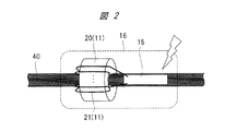
図2は、図1の通信可視化装置10に設けられた変成器11の一例を示す説明図である。
<Example of transformer>
FIG. 2 is an explanatory diagram showing an example of the
変成器11は、図2に示すように、フェライトコア20およびコイル21から構成されている。フェライトコア20は、例えばフェライトというセラミックの磁性体を中空円柱状、すなわちリング状に形成したものである。フェライトコア20のリングには、コイル21が巻き付けられている。
The
〈ケースの構成例〉
続いて、ケース16の構成および変成器11とプリント配線基板15とを収納する技術について、図3、および図4を用いて説明する。
<Example of case configuration>
Next, the configuration of the
図3は、変成器11およびプリント配線基板15を収納するケース16の一例を示す説明図である。図4は、変成器11とプリント配線基板15との具体的な接続構成例を示す説明図である。
FIG. 3 is an explanatory diagram showing an example of the
ケース16は、図3(a)に示すように、例えばプラスティックなどの合成樹脂からなり、2つのケースブロック17,18をそれぞれ有している。ケースブロック17,18は、中空の直方体の形状からそれぞれなる。
As shown in FIG. 3A, the
ケースブロック17,18の一方の長辺側には、図示しないヒンジが設けられており、支点となる該ヒンジを中心としてケースブロック17,18が開閉される。ケースブロック17,18の他方の長辺側には、ケースブロック17,18をクランプする図示しないクランパが形成されている。 A hinge (not shown) is provided on one long side of the case blocks 17 and 18, and the case blocks 17 and 18 are opened and closed around the hinge serving as a fulcrum. A clamper (not shown) that clamps the case blocks 17 and 18 is formed on the other long side of the case blocks 17 and 18.
ケースブロック17,18には、図3(b)に示すように、断面半円状の溝17aおよび溝18aがそれぞれ形成されている。ケースブロック17,18が組み合わされると、溝17aおよび溝18aによって円柱状のケーブル収納スペースが形成される。このケーブル収納スペースにLANケーブル40が収納される。
As shown in FIG. 3B, the case blocks 17 and 18 are formed with a
フェライトコア20は、図4に示すように、半円柱状に2分割されており、一方の半円柱状のフェライトコア20がケースブロック17の中空部分に収納され、他方の半円柱状のフェライトコア20がケースブロック18の中空部分に収納されている。
As shown in FIG. 4, the
また、ケースブロック18の中空部分の空きスペースには、プリント配線基板15が収納されている。ケースブロック18の中空部分に収納されている半円柱状のフェライトコア20には、コイル21が巻かれている。
A printed
このコイル21の両端部は、プリント配線基板15にそれぞれ接続されている。そして、プリント配線基板15において、該プリント配線基板15に形成された2本の配線パターン(図示せず)によって、整合回路12が接続される。
Both ends of the
ケース16をLANケーブル40に取り付ける際には、図3(b)に示すようにケースブロック17,18を開いた状態で、該LANケーブル40を溝17a,18aのいずれかに収納した後、図3(a)に示すようにケースブロック17,18を閉じる。そして、クランパによってケースブロック17,18をクランプする。これによって、通信可視化装置10は、LANケーブル40の任意の位置に取り付けられる。
When the
先に発明が解決しようとする課題でも述べたように、集積化された情報通信機器の奥まった場所に配線されたLANケーブル40を抜去する際、情報通信機器のLANコネクタに設けられた接続確認用のランプだけでは、抜去対象のLANケーブル40の識別が困難である。
As described above in connection with the problem to be solved by the invention, when the
そこで、LANケーブル40の任意の位置、例えばLANコネクタから少し離れた位置に通信可視化装置10を取り付けることにより、LANケーブル40の通信の有無を見分けることが容易となり、抜去対象であるLANケーブル40の誤抜を防止することができる。
Therefore, by attaching the
また、LANケーブル40に取り付けられた通信可視化装置10から、該LANケーブル40が接続されるコネクタまでをたどっていくことによって、対象のLANケーブル40に接続されているコネクタの位置の誤認を防止することができる。
Further, by tracing from the
さらに、ケース16に設けられたクランパによってケースブロック17,18をクランプするだけで、LANケーブル40の任意の位置に簡単に取り付けることができる。
Furthermore, it is possible to easily attach the
なお、図3では、ケース16がLANケーブル40に着脱自在な構成としたが、該ケースは、LANケーブル40に取り付けられると、該LANケーブル40から取り外しができないように、一体に取り付けられる構成としてもよい。
In FIG. 3, the
〈整合回路の例〉
図5は、図1の通信可視化装置10に設けられた整合回路12の一例を示す説明図である。
<Example of matching circuit>
FIG. 5 is an explanatory diagram showing an example of the matching
整合回路12は、インダクタ22,22aおよびコンデンサ23からなるLC回路からなる。インダクタ22の一方の接続部には、コイル21(図2)の一方の端部およびコンデンサ23の一方の接続部がそれぞれ接続されている。コンデンサ23の他方の接続部には、インダクタ22aの他方の接続部が接続されている。
The matching
また、コイル21の他方の端部には、インダクタ22の他方の接続部およびインダクタ22aの他方の接続部がそれぞれ接続されている。整合回路12は、いわゆるπ型整合回路であり、整合状態によってはコンデンサの代わりにインダクタを、またインダクタの代わりにコンデンサを使用してよい。また、整合状態によっては、インダクタ22を取り除いた構成、すなわちオープン終端としてもよい。
The other end of the
〈整流回路の例1〉
図6は、図1の通信可視化装置10に設けられた整流回路13の一例を示す説明図である。
<Example of rectifier circuit 1>
FIG. 6 is an explanatory diagram showing an example of the
整流回路13は、4つのダイオード24〜27からなる。ダイオード24のカソードおよびダイオード26のアノードには、図5に示すコンデンサ23とインダクタ22aとの接続部がそれぞれ接続されている。
The
ダイオード25のアノードおよびダイオード27のカソードには、図2のコイル21の他方の端部がそれぞれ接続されている。また、ダイオード25のカソードには、ダイオード24のアノードが接続され、ダイオード26のカソードには、ダイオード27のアノードが接続されている。
The other end of the
ダイオード26とダイオード27との接続部が正側(+)出力部となり、ダイオード24とダイオード25との接続部が負側(−)出力部となり、これら出力部から、直流電圧が出力される。
A connection portion between the
このように、整流回路13は、いわゆるブリッジ式全波整流回路からなる。全波整流回路を用いた場合には、後述する半波整流回路の場合よりも、高い電力変換効率を実現することができる。
Thus, the
〈整流回路の例2〉
図7は、図1の通信可視化装置10に設けられた整流回路13の他の例を示す説明図である。
<Example 2 of rectifier circuit>
FIG. 7 is an explanatory diagram showing another example of the
図6では、ブリッジ式全波整流回路の構成について示したが、整流回路13は、交流信号の半サイクルのみを整流する半波整流回路としてもよい。この場合、整流回路13は、図7に示すように、2つのダイオード28,29から構成される。
Although FIG. 6 shows the configuration of the bridge-type full-wave rectifier circuit, the
ダイオード28のアノードおよびダイオード29のカソードには、図5に示すコンデンサ23とインダクタ22aとの接続部がそれぞれ接続されている。ダイオード29のアノードには、図2のコイル21の他方の端部が接続されている。
A connection portion between the
半波整流回路の場合には、全波整流回路に比べて電力変換効率が低下するが、部品点数を少なくすることができるので、通信可視化装置10の小型化を可能とすることができる。
In the case of the half-wave rectifier circuit, the power conversion efficiency is lower than that of the full-wave rectifier circuit, but the number of parts can be reduced, so that the
〈発光回路の例〉
図8は、図1の通信可視化装置10に設けられた発光回路14の一例を示す説明図である。
<Example of light emitting circuit>
FIG. 8 is an explanatory diagram showing an example of the
発光回路14は、図示するように、発光ダイオード(LED:Light Emitting Diode)30、抵抗31、およびコンデンサ32からなる。発光ダイオード30のアノードおよびコンデンサ32の一方の接続部には、図6の整流回路13の正側(+)出力部となるダイオード26とダイオード27との接続部が接続されている。
The
発光ダイオード30のカソードには、抵抗31の一方の接続部が接続されている。抵抗31の他方の接続部およびコンデンサ32の他方の接続部には、図6の整流回路13の負側(−)出力部となるダイオード24とダイオード25との接続部がそれぞれ接続されている。
One connection portion of the
抵抗31およびコンデンサ32によってRC回路が構成され、該RC回路の時定数を設定することによって発光ダイオード30の発光間隔を任意に調整することができる。また、発光ダイオード30の発光間隔の調整が不要な場合には、抵抗31およびコンデンサ32を削除するようにしてもよい。
An RC circuit is configured by the
〈通信可視化装置の動作例〉
続いて、通信可視化装置10の動作について説明する。
<Operation example of communication visualization device>
Next, the operation of the
LANケーブル40を介して情報通信が開始されると、その通信によって変成器11のフェライトコア20内部に磁界が生じる。この結果、コイル21に電流が流れ、該電流が誘起した電圧が発生し、コイル21から交流の電気信号が出力される。
When information communication is started via the
変成器11によって発生した交流の電気信号は、整合回路12を介して整流回路13に出力される。整流回路13では、交流の電気信号を全波整流、あるいは半波整流によって整流して直流電圧を出力し、発光回路14に供給する。
The AC electrical signal generated by the
整流回路13から発光回路14に電力が供給されると、該発光回路14の発光ダイオード30が発光する。ここで、発光ダイオード30の発光間隔は、抵抗31およびコンデンサ32によるRC回路の時定数に依存する。
When power is supplied from the
また、LANケーブル40の情報通信が行われていない場合には、変成器11において電気信号が発生しないので、発光ダイオード30は、発光しないことになる。
Further, when the information communication of the
このように、通信可視化装置10は、情報通信時にLANケーブル40から漏洩する電磁エネルギを検出した際に、すなわちLANケーブル40が情報通信を行っているときにのみ発光ダイオード30が点灯する。
Thus, in the
これによって、視覚的にLANケーブル40が情報通信中であるか否かを判別することが可能となる。また、先に述べたように、通信可視化装置10は、LANケーブルの任意の位置に取りつけることができるので、データセンタなどのように多数のLANケーブル40の中から、対象のLANケーブルを容易に確認することが可能となり、LANケーブル40の誤抜を防止することができる。
This makes it possible to visually determine whether the
(実施の形態2)
〈概要〉
前記実施の形態1では、図1の変成器11によって高周波信号によって生じる磁界を交流の電気信号に変換した構成としたが、本実施の形態2では、変成器11を不要とする技術について説明する。
(Embodiment 2)
<Overview>
In the first embodiment, the magnetic field generated by the high-frequency signal is converted into an AC electrical signal by the
〈通信可視化装置の構成例〉
図9は、本発明の実施の形態2による通信可視化装置10の構成の一例を示す説明図である。
<Configuration example of communication visualization device>
FIG. 9 is an explanatory diagram showing an example of the configuration of the
通信可視化装置10は、図9に示すように、アンテナ33、整合回路12、整流回路13、発光回路14、およびプリント配線基板15を有する。
As illustrated in FIG. 9, the
図9において、前記実施の形態1の図1と異なるところは、変成器11の代わりに起電力生成部となるアンテナ33が設けられ、該アンテナ33がプリント配線基板15に搭載されている点である。
9 differs from FIG. 1 of the first embodiment in that an
なお、図9の整合回路12、整流回路13、および発光回路14については、前記実施の形態1の図1と同様であるので、説明は省略する。
Note that the matching
〈アンテナの構成例〉
図10は、図9の通信可視化装置10に設けられたプリント配線基板15の説明図である。
<Example of antenna configuration>
FIG. 10 is an explanatory diagram of the printed
アンテナ33は、プリント配線基板15の主面に形成されている。このアンテナ33は、例えば配線パターンによって形成されている。整合回路12、整流回路13、および発光回路14などを構成する回路部品は、プリント配線基板15の裏面に実装されている。プリント配線基板15は、図3に示したケースブロック17の中空部分に収納される。
The
プリント配線基板15に形成されるアンテナ33は、図示するように、2本の直線状の配線パターン33aおよび配線パターン33bからなる、いわゆるダイポール型アンテナである。
The
これら配線パターン33aおよび配線パターン33bは、LANケーブル40の幅方向に相互の間隔を隔て、該LANケーブル40の長手方向に延びるように、すなわちLANケーブル40の長手方向と並行するように形成されている。これによって、効率よく、LANケーブル40からの磁界を取得することができる。
The
LANでは、ケーブル内電気信号はデジタル信号であり、複数の周波数の正弦波信号の和となる。このため、ケーブル周囲に生じる磁界も複数の周波数成分を有する。配線パターン33a,33bの電気長を、これら複数の周波数のうち、いずれかの周波数の波長に対して1/4倍となるように設定することが望ましい。また、より波長の短い、高い周波数成分に対応させることで、アンテナの小型化が可能であり、装置の小型化を実現することが可能である。
In the LAN, the electrical signal in the cable is a digital signal, which is the sum of sine wave signals having a plurality of frequencies. For this reason, the magnetic field generated around the cable also has a plurality of frequency components. It is desirable to set the electrical length of the
また、配線パターン33aの一方の端部は、図5のインダクタ22とコンデンサ23との接続部がそれぞれ接続されており、配線パターン33bの一方の端部は、図6のダイオード24,25の接続部がそれぞれ接続されている。
Further, one end of the
配線パターン33aおよび配線パターン33bから形成されるアンテナ33によって、通信の際にLANケーブル40から漏洩する高周波信号によって生じる磁界が交流の電気信号に変換されることになる。
The
このように、アンテナ33をプリント配線基板15に形成することによって、変成器11が不要となる。これによって、通信可視化装置10の軽量化、小型化、および低コスト化などを実現することができる。
Thus, by forming the
(実施の形態3)
〈概要〉
前記実施の形態1の変成器11(図1)あるいは前記実施の形態2のアンテナ33(図10)が取得する磁界が弱い場合、十分な電力を取得できない状況が生じることが考えられる。
(Embodiment 3)
<Overview>
If the magnetic field acquired by the transformer 11 (FIG. 1) of the first embodiment or the antenna 33 (FIG. 10) of the second embodiment is weak, a situation where sufficient power cannot be acquired may occur.
そこで、本実施の形態3では、変成器11(図1)またはアンテナ33(図10)で十分な電力を取得できない場合であっても、発光回路14の発光ダイオード30を発光させることのできる技術について説明する。
Therefore, in the third embodiment, even when the transformer 11 (FIG. 1) or the antenna 33 (FIG. 10) cannot obtain sufficient power, the technology capable of causing the
〈通信可視化装置の構成例〉
図11は、本発明の実施の形態3による通信可視化装置10の構成の一例を示す説明図である。
<Configuration example of communication visualization device>
FIG. 11 is an explanatory diagram showing an example of the configuration of the
通信可視化装置10は、図11に示すように、アンテナ33、整合回路12、整流回路13、発光回路14、およびプリント配線基板15からなる図9の構成に、新たにスイッチ回路34が設けられた構成からなる。また、スイッチ回路34の回路は、プリント配線基板15に実装される。
As shown in FIG. 11, the
なお、図11のアンテナ33、整合回路12、整流回路13、および発光回路14については、図9と同様であるので、説明は省略する。図11では、アンテナ33、整合回路12、整流回路13、発光回路14、およびプリント配線基板15からなる図9の構成に、新たにスイッチ回路34が設けられた構成としたが、図1の構成に、新たにスイッチ回路34を設けた構成としてもよい。
Note that the
〈スイッチ回路の構成例〉
図12は、図11の通信可視化装置10に設けられたスイッチ回路34の一例を示す説明図である。
<Configuration example of switch circuit>
FIG. 12 is an explanatory diagram showing an example of the
スイッチ回路34は、図示するように、コンデンサ35およびスイッチ36を有する。充電部となるコンデンサ35の一方の接続部およびスイッチ36の一端は、整流回路13(図6)の正側(+)出力部、すなわちダイオード26とダイオード27との接続部に接続されている。
The
また、コンデンサ35の他方の接続部には、整流回路13の負側(−)出力部、すなわちダイオード24とダイオード25との接続部がそれぞれ接続されている。スイッチ36の他端には、発光回路14(図8)のコンデンサ32の一方の接続部および発光ダイオード30のアノードがそれぞれ接続されている。そして、スイッチ36のオン/オフを制御する制御端子には、コンデンサ35に充電される電圧が印加されるように接続されている。
Further, the negative side (−) output portion of the
整流回路13によって変換された直流電圧は、コンデンサ35によって充電される。そして、コンデンサ35に充電され、コンデンサ35とスイッチ36との接続部の電圧が十分に高くなると、その電圧によってスイッチ36がオンとなり、発光回路14に電力が供給される。
The DC voltage converted by the
このように、整流回路13が変換した直流電圧をコンデンサ35に蓄電させ、十分な電圧レベルになった際に発光回路14に電力を供給するので、発光ダイオード30が発光しないことを防止することができる。
In this way, the direct current voltage converted by the
スイッチ36としてMEMS(Micro Electron Mechanical System)スイッチを用いてもよい。コンデンサ35から一定値以上の電圧がMEMSスイッチに印加されると、MEMSスイッチがオン状態となり、発光回路14に電力が供給される。
A MEMS (Micro Electron Mechanical System) switch may be used as the
また、スイッチ回路34は、スイッチ36の代わりとしてダイオードを順方向接続する構成としてもよい。この場合、コンデンサ35とスイッチ36との接続部の電圧がダイオードの順電圧Vfよりも高くなると、発光回路14に電力が供給されることになる。
The
以上により、通信可視化装置10の信頼性を向上させることができる。
As described above, the reliability of the
以上、本発明者によってなされた発明を実施の形態に基づき具体的に説明したが、本発明は前記実施の形態に限定されるものではなく、その要旨を逸脱しない範囲で種々変更可能であることはいうまでもない。 As mentioned above, the invention made by the present inventor has been specifically described based on the embodiment. However, the present invention is not limited to the embodiment, and various modifications can be made without departing from the scope of the invention. Needless to say.
なお、本発明は上記した実施の形態に限定されるものではなく、様々な変形例が含まれる。例えば、上記した実施の形態は本発明を分かりやすく説明するために詳細に説明したものであり、必ずしも説明した全ての構成を備えるものに限定されるものではない。 In addition, this invention is not limited to above-described embodiment, Various modifications are included. For example, the above-described embodiment has been described in detail for easy understanding of the present invention, and is not necessarily limited to one having all the configurations described.
また、ある実施の形態の構成の一部を他の実施の形態の構成に置き換えることが可能であり、また、ある実施の形態の構成に他の実施の形態の構成を加えることも可能である。また、各実施の形態の構成の一部について、他の構成の追加、削除、置換をすることが可能である。 Further, a part of the configuration of one embodiment can be replaced with the configuration of another embodiment, and the configuration of another embodiment can be added to the configuration of one embodiment. . In addition, it is possible to add, delete, and replace other configurations for a part of the configuration of each embodiment.
10 通信可視化装置
11 変成器(起電力生成部)
12 整合回路(整合部)
13 整流回路(整流部)
14 発光回路(発光部)
15 プリント配線基板
16 ケース
17 ケースブロック
17a 溝
18 ケースブロック
18a 溝
20 フェライトコア
21 コイル
22 インダクタ
22a インダクタ
23 コンデンサ
24 ダイオード
25 ダイオード
26 ダイオード
27 ダイオード
28 ダイオード
29 ダイオード
30 発光ダイオード
31 抵抗
32 コンデンサ
33 アンテナ
33a 配線パターン
33b 配線パターン
34 スイッチ回路
35 コンデンサ(充電部)
36 スイッチ
40 LANケーブル(通信ケーブル)
10
12 Matching circuit (matching part)
13 Rectifier circuit (rectifier unit)
14 Light emitting circuit (light emitting part)
15 Printed
36
Claims (7)
前記起電力生成部が生成した電気エネルギを直流電圧に変換する整流部と、
前記起電力生成部と前記整流部との間に配置されるとともに前記起電力生成部及び前記整流部に接続され、前記起電力生成部と前記整流部とのインピーダンスを調整する整合部と、
前記整流部が変換した直流電圧が供給された際に発光する発光部と、
を有する、通信可視化装置。 At the time of information communication, an electromotive force generation unit that converts a magnetic field generated from a LAN cable connected to the information communication device into electric energy;
A rectifier that converts the electrical energy generated by the electromotive force generator into a DC voltage;
A matching unit that is disposed between the electromotive force generation unit and the rectification unit and connected to the electromotive force generation unit and the rectification unit, and adjusts an impedance between the electromotive force generation unit and the rectification unit;
A light emitting unit that emits light when a DC voltage converted by the rectifying unit is supplied;
A communication visualization device.
前記起電力生成部は、
前記LANケーブルの通信によって磁界を発生させるフェライトコアと、
前記フェライトコアに巻き付けられ、前記フェライトコアが発生させた磁界によって発生した電流が誘起した電圧を出力するコイルと、
を有する、通信可視化装置。 The communication visualization device according to claim 1,
The electromotive force generator is
A ferrite core that generates a magnetic field by communication of the LAN cable;
A coil that is wound around the ferrite core and outputs a voltage induced by a current generated by the magnetic field generated by the ferrite core;
A communication visualization device.
前記起電力生成部は、ダイポールアンテナである、通信可視化装置。 The communication visualization device according to claim 1,
The communication visualization device, wherein the electromotive force generation unit is a dipole antenna.
前記ダイポールアンテナは、配線パターンによってプリント配線基板に形成される、通信可視化装置。 The communication visualization device according to claim 3, wherein
The communication visualization apparatus, wherein the dipole antenna is formed on a printed wiring board by a wiring pattern.
さらに、前記整流部から出力される直流電圧を充電する充電部と、
前記充電部の充電電圧が、設定した電圧レベル以上となった際に、充電した前記直流電圧を前記発光部に供給するスイッチと、
を有する、通信可視化装置。 In the communication visualization device according to any one of claims 1 to 4 ,
Furthermore, a charging unit that charges a DC voltage output from the rectifying unit;
A switch for supplying the charged DC voltage to the light emitting unit when a charging voltage of the charging unit is equal to or higher than a set voltage level;
A communication visualization device.
前記起電力生成部、前記整流部、前記整合部、および前記発光部を収納するケースを有し、
前記起電力生成部は、前記LANケーブルの通信によって磁界を発生させる円筒状のフェライトコアと、前記フェライトコアに巻き付けられ、前記フェライトコアが発生させた磁界によって発生した電流が誘起した電圧を出力するコイルと、を有し、
前記ケースは、2つのケースブロックが組み合わされることにより形成され、
前記フェライトコアは、半円筒状に2分割されているとともに、前記コイルは、前記2分割されたフェライトコアの一方に巻き付けられており、
前記コイルが巻き付けられている前記2分割されたフェライトコアの一方、前記整流部、前記整合部、および前記発光部は、前記2つのケースブロックの一方に収納されており、
前記2分割されたフェライトコアの他方は、前記2つのケースブロックの他方に収納されており、
前記ケースは、前記LANケーブルに着脱自在に装着される、通信可視化装置。 The communication visualization device according to claim 1,
The electromotive force generation unit, the rectification unit, the matching unit, and a case that houses the light emitting unit,
The electromotive force generation unit outputs a voltage induced by a cylindrical ferrite core that generates a magnetic field by communication of the LAN cable, and a current generated by the magnetic field generated by the ferrite core wound around the ferrite core. A coil, and
The case is formed by combining two case blocks,
The ferrite core is divided into two semicylindrical shapes, and the coil is wound around one of the two divided ferrite cores,
One of the two divided ferrite cores around which the coil is wound, the rectifying unit, the matching unit, and the light emitting unit are housed in one of the two case blocks,
The other of the two divided ferrite cores is housed in the other of the two case blocks,
The communication visualization device, wherein the case is detachably attached to the LAN cable.
前記起電力生成部、前記整流部、および前記発光部を収納するケースを有し、
前記ケースは、前記LANケーブルに一体に取り付けられる、通信可視化装置。
The communication visualization device according to claim 1,
A case housing the electromotive force generation unit, the rectification unit, and the light emitting unit;
The communication visualization device, wherein the case is integrally attached to the LAN cable.
Priority Applications (1)
| Application Number | Priority Date | Filing Date | Title |
|---|---|---|---|
| JP2014039316A JP6244983B2 (en) | 2014-02-28 | 2014-02-28 | Communication visualization device |
Applications Claiming Priority (1)
| Application Number | Priority Date | Filing Date | Title |
|---|---|---|---|
| JP2014039316A JP6244983B2 (en) | 2014-02-28 | 2014-02-28 | Communication visualization device |
Publications (2)
| Publication Number | Publication Date |
|---|---|
| JP2015164241A JP2015164241A (en) | 2015-09-10 |
| JP6244983B2 true JP6244983B2 (en) | 2017-12-13 |
Family
ID=54187021
Family Applications (1)
| Application Number | Title | Priority Date | Filing Date |
|---|---|---|---|
| JP2014039316A Active JP6244983B2 (en) | 2014-02-28 | 2014-02-28 | Communication visualization device |
Country Status (1)
| Country | Link |
|---|---|
| JP (1) | JP6244983B2 (en) |
Family Cites Families (7)
| Publication number | Priority date | Publication date | Assignee | Title |
|---|---|---|---|---|
| JPS57159169U (en) * | 1981-03-31 | 1982-10-06 | ||
| JPS6035265U (en) * | 1983-08-17 | 1985-03-11 | 株式会社 ユ−・ア−ル・デイ− | No-power digital AC ammeter |
| JPH04120471A (en) * | 1990-09-10 | 1992-04-21 | Onuki Kenji | Signal detector |
| JPH0455576U (en) * | 1990-09-21 | 1992-05-13 | ||
| JP2002257879A (en) * | 2001-03-02 | 2002-09-11 | Nippon Telegraph & Telephone East Corp | Noise detection device and detection method |
| JP4070981B2 (en) * | 2001-11-16 | 2008-04-02 | パイオニア株式会社 | communication cable |
| JP2006004683A (en) * | 2004-06-16 | 2006-01-05 | Showa Electric Wire & Cable Co Ltd | Cable with identification information and cable power transmission monitoring device |
-
2014
- 2014-02-28 JP JP2014039316A patent/JP6244983B2/en active Active
Also Published As
| Publication number | Publication date |
|---|---|
| JP2015164241A (en) | 2015-09-10 |
Similar Documents
| Publication | Publication Date | Title |
|---|---|---|
| JP7502373B2 (en) | Wireless Connector System | |
| US10110075B2 (en) | System and method for selecting power transmitters across a wireless power coupling | |
| US20150214752A1 (en) | Wireless power outlet | |
| ES2894931T3 (en) | Efficiency monitor for inductive power transmission | |
| KR101322764B1 (en) | Apparatus and method for wireless power transmition | |
| US9226351B2 (en) | Compact converter plug for LED light strings | |
| JP6252373B2 (en) | Communication cable connector and communication cable with connector | |
| JP6489523B2 (en) | Solid state light emitting device module and lighting set | |
| JP5143629B2 (en) | Power line carrier communication equipment | |
| JP6244983B2 (en) | Communication visualization device | |
| JP6221834B2 (en) | Communication visualization system | |
| KR101232788B1 (en) | Apparatus for wireless charging battery with package chip and system thereof | |
| JP6112043B2 (en) | Communication visualization system | |
| DK176584B1 (en) | Headset with rechargeable battery, base unit designed to charge a rechargeable battery as well as a communication device | |
| JP6112044B2 (en) | Communication visualization system | |
| WO2022046295A1 (en) | Dual electronic device wireless charger | |
| JP6295878B2 (en) | Communication visualization system | |
| JP6331847B2 (en) | Communication visualization device | |
| JP2016035427A (en) | Communication visualization device | |
| Kweku | Wireless mobile charger using inductive coupling | |
| US9265129B2 (en) | Adapter cable having light source for lighting | |
| KR20180011606A (en) | Wireless Power Transmitter and Wireless Power Receiver | |
| KR102675983B1 (en) | Wireless power transmission apparatus | |
| CN108257770B (en) | Coil unit and coil device capable of generating uniform magnetic field | |
| CN101218526A (en) | Apparatus for generating electrical signals and having light emitting means for characterizing said signals |
Legal Events
| Date | Code | Title | Description |
|---|---|---|---|
| A621 | Written request for application examination |
Free format text: JAPANESE INTERMEDIATE CODE: A621 Effective date: 20160520 |
|
| A977 | Report on retrieval |
Free format text: JAPANESE INTERMEDIATE CODE: A971007 Effective date: 20170224 |
|
| A131 | Notification of reasons for refusal |
Free format text: JAPANESE INTERMEDIATE CODE: A131 Effective date: 20170307 |
|
| A521 | Request for written amendment filed |
Free format text: JAPANESE INTERMEDIATE CODE: A523 Effective date: 20170502 |
|
| TRDD | Decision of grant or rejection written | ||
| A01 | Written decision to grant a patent or to grant a registration (utility model) |
Free format text: JAPANESE INTERMEDIATE CODE: A01 Effective date: 20171017 |
|
| A61 | First payment of annual fees (during grant procedure) |
Free format text: JAPANESE INTERMEDIATE CODE: A61 Effective date: 20171030 |
|
| R150 | Certificate of patent or registration of utility model |
Ref document number: 6244983 Country of ref document: JP Free format text: JAPANESE INTERMEDIATE CODE: R150 |
|
| S531 | Written request for registration of change of domicile |
Free format text: JAPANESE INTERMEDIATE CODE: R313531 |
|
| S533 | Written request for registration of change of name |
Free format text: JAPANESE INTERMEDIATE CODE: R313533 |
|
| R350 | Written notification of registration of transfer |
Free format text: JAPANESE INTERMEDIATE CODE: R350 |