JP6234174B2 - Substrate processing equipment - Google Patents
Substrate processing equipment Download PDFInfo
- Publication number
- JP6234174B2 JP6234174B2 JP2013231733A JP2013231733A JP6234174B2 JP 6234174 B2 JP6234174 B2 JP 6234174B2 JP 2013231733 A JP2013231733 A JP 2013231733A JP 2013231733 A JP2013231733 A JP 2013231733A JP 6234174 B2 JP6234174 B2 JP 6234174B2
- Authority
- JP
- Japan
- Prior art keywords
- substrate
- fluid
- temperature
- processing apparatus
- hot water
- Prior art date
- Legal status (The legal status is an assumption and is not a legal conclusion. Google has not performed a legal analysis and makes no representation as to the accuracy of the status listed.)
- Expired - Fee Related
Links
Images


Landscapes
- Weting (AREA)
- Exposure Of Semiconductors, Excluding Electron Or Ion Beam Exposure (AREA)
Description
本発明は、基板を加熱するとともに基板を回転させながら基板に処理液を供給することにより基板に所定の処理、例えば、洗浄処理またはエッチング処理などを行う基板処理技術に関する。 The present invention relates to a substrate processing technique for performing predetermined processing, for example, cleaning processing or etching processing, on a substrate by heating the substrate and supplying a processing liquid to the substrate while rotating the substrate.
このような基板処理技術として、特許文献1には、予め温度制御された流体を基板下面の中心部と周辺部との間の複数の箇所に供給するともに、基板上面に処理液を噴射して基板を処理する基板処理装置が開示されている。当該装置は、基板の下方の複数の箇所からそれぞれ供給される各流体の温度を制御する各温度制御部を備えている。そして、各流体は、基板へ供給される位置が基板の中心部から周辺部にゆくにつれて温度が高くなるように、各温度制御部によって別々に温度制御されている。これにより、該装置は、基板の中心部と周辺部との周速度の差に起因する基板の温度差を抑制し、処理液による基板処理の均一化を図っている。
As such a substrate processing technique,
しかしながら、特許文献1の基板処理装置には、温度制御部の個数が増加して装置の製造コストが増大するとともに、温度制御が複雑化するといった問題がある。
However, the substrate processing apparatus of
本発明は、こうした問題を解決するためになされたもので、基板処理装置の製造コストを抑制するとともに温度制御の複雑化を回避しつつ基板の温度を均一化できる技術を提供することを目的とする。 The present invention has been made to solve these problems, and an object of the present invention is to provide a technique capable of reducing the manufacturing cost of the substrate processing apparatus and making the temperature of the substrate uniform while avoiding complicated temperature control. To do.
第1の態様に係る基板処理装置は、基板を略水平姿勢にて保持する基板保持部と、前記基板保持部に保持された前記基板を略水平面内にて回転させる回転部と、前記回転部により回転されている前記基板の下面に第1温度以上の温度調整用流体を吐出する流体吐出部と、前記温度調整用流体を吐出されている前記基板の上面に前記基板を処理するための処理液を吐出する処理液吐出部と、を備え、前記流体吐出部は、前記温度調整用流体が前記第1温度に設定された第1流体を前記基板の下面の中央域に対して吐出する処理と、前記温度調整用流体が前記第1温度よりも高い第2温度に設定された第2流体を前記基板の下面の周辺域に対して吐出する処理と、前記第1流体と前記第2流体とを前記基板の下面における前記中央域と前記周辺域との間の中間域に対して吐出する処理と、を並行して行い、前記流体吐出部は、前記中央域に前記第1流体を吐出する第1吐出口と、前記中間域に前記第1流体を吐出する第2吐出口とを備えるとともに、前記中間域に前記第2流体を吐出する第3吐出口と前記周辺域に前記第2流体を吐出する第4吐出口とを備え、前記第2吐出口と前記基板中心との基板径方向に沿った第1距離が、前記第3吐出口と前記基板中心との基板径方向に沿った第2距離に比べて同じであるか、あるいは長い。 A substrate processing apparatus according to a first aspect includes a substrate holding unit that holds a substrate in a substantially horizontal posture, a rotating unit that rotates the substrate held by the substrate holding unit in a substantially horizontal plane, and the rotating unit. A fluid discharge unit that discharges a temperature adjustment fluid having a temperature equal to or higher than a first temperature to the lower surface of the substrate rotated by the substrate, and a process for processing the substrate on the upper surface of the substrate from which the temperature adjustment fluid is discharged A treatment liquid discharge section that discharges the liquid, and the fluid discharge section discharges the first fluid in which the temperature adjusting fluid is set to the first temperature to a central area of the lower surface of the substrate. And a process of discharging the second fluid, which is set to a second temperature higher than the first temperature, to the peripheral area of the lower surface of the substrate, and the first fluid and the second fluid. And the central area and the peripheral area on the lower surface of the substrate There performing parallel processing and a to discharge the intermediate zone between the fluid ejecting unit includes a first discharge port for discharging said first fluid into the central region, the first to the intermediate zone A second discharge port for discharging a fluid, a third discharge port for discharging the second fluid to the intermediate region, and a fourth discharge port for discharging the second fluid to the peripheral region, The first distance along the substrate radial direction between the two discharge ports and the substrate center is the same as or longer than the second distance along the substrate radial direction between the third discharge port and the substrate center. .
第2の態様に係る基板処理装置は、第1の態様に係る基板処理装置であって、前記流体吐出部は、前記基板の下方に設けられ、前記中央域と前記中間域とに前記第1流体を吐出する第1ノズルと、前記基板の下方に設けられ、前記中間域と前記周辺域とに前記第2流体を吐出する第2ノズルと、を備える。 The substrate processing apparatus which concerns on a 2nd aspect is a substrate processing apparatus which concerns on a 1st aspect, Comprising: The said fluid discharge part is provided below the said board | substrate, and the said 1st area is provided in the said center area and the said intermediate area. A first nozzle that discharges fluid; and a second nozzle that is provided below the substrate and that discharges the second fluid to the intermediate region and the peripheral region.
第3の態様に係る基板処理装置は、第1または第2の態様に係る基板処理装置であって、前記第1距離が、前記第2距離に比べて長い。 The substrate processing apparatus according to a third aspect is the substrate processing apparatus according to the first or second aspect, wherein the first distance is longer than the second distance.
第4の態様に係る基板処理装置は、第1から第3の何れか1つの態様に係る基板処理装置であって、前記第2流体に前記第1温度よりも低温の前記温度調整用流体を混合することにより前記第1流体を調製する。 A substrate processing apparatus according to a fourth aspect is the substrate processing apparatus according to any one of the first to third aspects, wherein the temperature adjusting fluid having a temperature lower than the first temperature is added to the second fluid. The first fluid is prepared by mixing.
第5の態様に係る基板処理装置は、第1から第4の何れか1つの態様に係る基板処理装置であって、前記処理液と前記第1流体とが略同じ温度に設定されている。 A substrate processing apparatus according to a fifth aspect is the substrate processing apparatus according to any one of the first to fourth aspects, wherein the processing liquid and the first fluid are set at substantially the same temperature.
第6の態様に係る基板処理装置は、第1から第5の何れか1つの態様に係る基板処理装置であって、前記温度調整用流体は液体であり、前記第1流体に基づいて前記処理液を調製する。 A substrate processing apparatus according to a sixth aspect is the substrate processing apparatus according to any one of the first to fifth aspects, wherein the temperature adjusting fluid is a liquid, and the processing based on the first fluid is performed. Prepare the solution.
第7の態様に係る基板処理装置は、第1から第6の何れか1つの態様に係る基板処理装置であって、前記温度調整用流体は、純水である。 A substrate processing apparatus according to a seventh aspect is the substrate processing apparatus according to any one of the first to sixth aspects, wherein the temperature adjusting fluid is pure water.
第1から第7の何れの態様に係る発明によっても、流体吐出部は、基板の下面の中央域と中間域とに、温度調整用流体が第1温度に設定された第1流体を吐出しつつ、基板の下面の中間域と周辺域とに温度調整用流体が第1温度よりも高い第2温度に設定された第2流体を吐出する。中間域に吐出された第1流体と第2流体とは、基板の回転によって、混ざり合う。混ざり合った流体の温度は第1温度と第2温度との間の温度となる。すなわち、第1温度の第1流体と第2温度の第2流体とを基板下面に対して吐出することによって、吐出された後の、基板の下面における温度調整用流体の温度を、中央域から周辺域にゆくにつれて高温になる少なくとも3段階の温度にすることができる。これにより、基板の中央域から周辺域にゆくにつれて高温になるように予め温度制御した流体を基板に吐出することなく、すなわち、基板処理装置の製造コストを抑制するとともに温度制御の複雑化を回避しつつ、基板の温度を均一化できる。 In any of the first to seventh aspects of the invention, the fluid discharge unit discharges the first fluid in which the temperature adjusting fluid is set to the first temperature in the central region and the intermediate region of the lower surface of the substrate. Meanwhile, the second fluid in which the temperature adjusting fluid is set to the second temperature higher than the first temperature is discharged to the intermediate region and the peripheral region on the lower surface of the substrate. The first fluid and the second fluid discharged to the intermediate region are mixed by the rotation of the substrate. The temperature of the mixed fluid is a temperature between the first temperature and the second temperature. That is, by discharging the first fluid having the first temperature and the second fluid having the second temperature to the lower surface of the substrate, the temperature of the temperature adjusting fluid on the lower surface of the substrate after being discharged is changed from the central region. The temperature can be set to at least three stages that increase in temperature toward the surrounding area. As a result, the fluid whose temperature is controlled in advance so as to become higher as it goes from the central region to the peripheral region of the substrate is not discharged to the substrate, that is, the manufacturing cost of the substrate processing apparatus is suppressed and the complexity of the temperature control is avoided. However, the temperature of the substrate can be made uniform.
第2の態様に係る発明によれば、基板処理装置は、中央域と中間域とに第1流体を吐出する第1ノズルと、中間域と周辺域とに第2流体を吐出する第2ノズルとを備える。これにより、ノズルの増加を抑制して流体吐出部を小さくできるので、基板処理装置の製造コストを抑制できる。 According to the second aspect of the invention, the substrate processing apparatus includes a first nozzle that discharges the first fluid to the central region and the intermediate region, and a second nozzle that discharges the second fluid to the intermediate region and the peripheral region. With. Thereby, since the increase in a nozzle can be suppressed and a fluid discharge part can be made small, the manufacturing cost of a substrate processing apparatus can be suppressed.
第1の態様に係る発明によれば、基板処理装置の流体吐出部は、中央域に第1流体を吐出する第1吐出口と、中間域に第1流体を吐出する第2吐出口とを備えるとともに、中間域に第2流体を吐出する第3吐出口と周辺域に第2流体を吐出する第4吐出口とを備える。これにより、吐出口の個数を低減して流体吐出部の構造を簡略化できるので、基板処理装置の製造コストを抑制することができる。 According to the first aspect of the invention, the fluid discharge unit of the substrate processing apparatus includes the first discharge port that discharges the first fluid to the central region and the second discharge port that discharges the first fluid to the intermediate region. And a third discharge port for discharging the second fluid to the intermediate region and a fourth discharge port for discharging the second fluid to the peripheral region. Thereby, since the number of discharge ports can be reduced and the structure of the fluid discharge part can be simplified, the manufacturing cost of the substrate processing apparatus can be suppressed.
第1の態様に係る発明によれば、中間域において、第2流体よりも低温の第1流体が、第2流体に比べて、基板中心からの基板径方向の距離が同じ位置か、あるいは当該距離がより長い位置に吐出される。これにより、当該距離がより短い位置に第1流体が吐出される場合に比べて基板温度を容易に均一化することができる。 According to the first aspect of the present invention, in the intermediate region, the first fluid having a temperature lower than that of the second fluid has the same distance in the substrate radial direction from the substrate center as compared with the second fluid, or It is discharged at a longer distance. Thereby, compared with the case where the 1st fluid is discharged to the position where the said distance is shorter, substrate temperature can be equalized easily.
第3の態様に係る発明によれば、中間域において、第2流体よりも低温の第1流体が、第2流体に比べて、基板中心からの基板径方向の距離がより長い位置に吐出される。これにより、基板温度をさらに容易に均一化することができる。 According to the third aspect of the invention, in the intermediate region, the first fluid having a temperature lower than that of the second fluid is discharged to a position where the distance in the substrate radial direction from the substrate center is longer than that of the second fluid. The Thereby, the substrate temperature can be made uniform more easily.
第4の態様に係る発明によれば、第2流体に第1温度よりも低温の温度調整用流体を混合することにより第1流体が調製されるので、第1流体用の温度調整機構が不要となり、基板処理装置の製造コストを抑制することができる。 According to the fourth aspect of the invention, since the first fluid is prepared by mixing the second fluid with the temperature adjusting fluid having a temperature lower than the first temperature, the temperature adjusting mechanism for the first fluid is unnecessary. Thus, the manufacturing cost of the substrate processing apparatus can be suppressed.
第5の態様に係る発明によれば、処理液と第1流体とは、略同じ温度に設定されている。従って、第1流体および第2流体の吐出によって温められた基板が、処理液によって冷却されることを抑制できるので、基板の処理効率の低下を抑制できる。 According to the fifth aspect of the invention, the processing liquid and the first fluid are set to substantially the same temperature. Therefore, since it can suppress that the board | substrate warmed by discharge of the 1st fluid and the 2nd fluid is cooled with a process liquid, the fall of the processing efficiency of a board | substrate can be suppressed.
第6の態様に係る発明によれば、基板に供給される処理液が第1流体に基づいて調製されるので、処理液と第1流体との温度を別々に制御する場合に比べて簡略な温度制御によって処理液と第1流体とを略同じ温度に設定することができる。
According to the sixth aspect of the invention, since the processing liquid supplied to the substrate is prepared based on the first fluid, it is simpler than the case where the temperatures of the processing liquid and the first fluid are controlled separately. The treatment liquid and the first fluid can be set to substantially the same temperature by temperature control.
以下、本発明の実施形態を図面に基づいて説明する。図面では同様な構成および機能を有する部分に同じ符号が付され、下記説明では重複説明が省略される。また、各図面は模式的に示されたものである。また、実施形態の説明において、上下方向は、鉛直方向であり、基板W側が上で、スピンチャック111側が下である。
Hereinafter, embodiments of the present invention will be described with reference to the drawings. In the drawings, parts having the same configuration and function are denoted by the same reference numerals, and redundant description is omitted in the following description. Each drawing is schematically shown. In the description of the embodiment, the vertical direction is the vertical direction, the substrate W side is up, and the
<実施形態について>
<1.基板処理装置の構成>
図1は実施形態に係る基板処理装置100の概略構成の一例を模式的に示す図である。図2は、基板Wの上方から基板Wの下方に設けられたノズルユニット140を透視した図である。ノズルユニット140は、ノズル(「第1ノズル」とも称される)141と、ノズル(「第2ノズル」とも称される)142を備えており、図2において実線で示されている。
<About the embodiment>
<1. Configuration of substrate processing apparatus>
FIG. 1 is a diagram schematically illustrating an example of a schematic configuration of a
基板処理装置100は、処理液を用いて基板の処理を行う。具体的には、基板処理装置100は、処理液として、例えば、エッチング液を用いて半導体ウエハ等の基板Wの上面(「表面」とも称される)S1のエッチング処理を行って、上面S1に形成されている薄膜(不要物)の除去を行う。なお、上面S1と反対側の下面S2は、「裏面」とも称される。基板Wの表面形状は略円形であり、基板Wの上面S1とはデバイスパターンが形成されるデバイス形成面を意味している。
The
なお、エッチング処理に用いられるエッチング液に限らず、化学的な処理液の多くは、温度が上昇するに伴って反応速度が速くなるという一般的なアレニウスの式に従う。つまり、多くの処理液が、温度が高いほど反応速度が速くなる処理液に属する。 In addition, not only the etching solution used for the etching process but many chemical processing solutions follow a general Arrhenius equation that the reaction rate increases as the temperature rises. That is, many processing liquids belong to the processing liquid whose reaction rate increases as the temperature increases.
図1に示されるように、基板処理装置100は、上面S1を上方に向けた状態で基板Wを略水平姿勢に保持して回転させるスピンチャック(「基板保持部」)111を備えている。スピンチャック111は、円筒状の回転支軸113がモータを含むチャック回転機構(「回転部」)163の回転軸に連結されており、チャック回転機構163の駆動により回転軸(鉛直軸)a1回りに、すなわち略水平面内にて回転可能となっている。
As shown in FIG. 1, the
回転支軸113の上端部には、円盤状のスピンベース115がネジなどの締結部品によって一体的に連結されている。したがって、装置全体を制御する制御部161からの動作指令に応じてチャック回転機構163が作動することによって、回転支軸113とスピンベース115とは、一体的に、回転軸a1を中心に回転する。また、制御部161はチャック回転機構163を制御して回転速度を調整する。制御部161は、例えば、CPUがメモリに記憶されたプログラムを実行することなどにより実現される。
A disc-shaped
スピンベース115の周縁部付近には、基板Wの周縁部S3を把持するための複数個のチャックピン117が立設されている。チャックピン117は、円形の基板Wを確実に保持するために3個以上設けてあればよく、スピンベース115の周縁部に沿って等角度間隔で配置されている。チャックピン117のそれぞれは、基板Wの周縁部S3を下方から支持する基板支持部と、基板支持部に支持された周縁部S3を押圧して基板Wを保持する基板保持部とを備えている。各チャックピン117は、基板保持部が基板Wの周縁部S3を押圧する押圧状態と、基板保持部が周縁部S3から離れる解放状態との間を切り替え可能に構成されている。
Near the periphery of the
スピンベース115に対して基板Wが受渡しされる際には、基板処理装置100は、複数個のチャックピン117を解放状態とし、基板Wに対してエッチング処理を行う際には、複数個のチャックピン117を押圧状態とする。押圧状態とすることによって、複数個のチャックピン117は、基板Wの周縁部S3を把持して基板Wをスピンベース115から所定間隔を隔てて略水平姿勢に保持することができる。これにより、基板Wはその表面(パターン形成面)S1を上方に向け、下面S2を下方に向けた状態で支持される。
When the substrate W is delivered to the
スピンベース115の中央部には、回転支軸113の貫通孔に接続された貫通孔が形成されている。これらの貫通孔には、供給管181、182が挿通されている。供給管181、182の上端には、基板Wの下面S2に沿って延設された長尺状のノズル141、142を備えるノズルユニット(「流体吐出部」とも称される)140が接続されて固定されている。ノズル141、142は、基板Wの下面S2の中央域K1において、一端側を供給管181、182によってそれぞれ支持されている。ノズル142の他端は、下面S2の周辺域K3の下方に達しており、ノズル141の他端は、中央域K1と周辺域K3との間の中間域K2に達している。回転するスピンベース115に立設されたチャックピン117とノズルユニット140とが干渉しないように、回転軸a1からノズル142の他端までの長さは、チャックピン117の回転軌跡の径よりも小さく設定されている。
A through hole connected to the through hole of the
なお、中間域K2とは、基板Wのうち、基板Wの中心からの径方向に沿った距離、すなわち、回転軸a1からの径方向に沿った距離が、好ましくは、基板の半径の1/3から基板の半径の2/3である領域である。具体的には、例えば、半径150mmの基板における中間域K2は、基板Wの中心からの距離が、好ましくは、50mm〜100mmである領域である。図2において、中央域K1は、一点鎖線の円で囲まれて、破線の斜線でハッチングされた領域である。周辺域K3は、基板Wの周縁と、二点鎖線の円との間の、網点パターンを付された領域である。そして、中間域K2は、中央域K1と周辺域K3との間の領域である。また、基板Wの回転軸a1から吐出口152までの基板Wの径方向に沿った距離(「第1距離」)L1と、回転軸a1から吐出口153までの基板Wの径方向に沿った距離(「第2距離」)L2とは、距離L1が、距離L2に比べて、同じであるか、あるいは長いことが好ましい。さらに、図2に示されるように、距離L1が、距離L2に比べて長くなるように設定されることがより好ましい。なお、距離L1が距離L2よりも短いとしても本発明の有用性を損なうものではない。距離L1、L2の関係については、後述する。
The intermediate region K2 is preferably a distance along the radial direction from the center of the substrate W, that is, a distance along the radial direction from the rotation axis a1, of the substrate W, preferably 1 / of the radius of the substrate. This is a region from 3 to 2/3 of the radius of the substrate. Specifically, for example, the intermediate region K2 in the substrate having a radius of 150 mm is a region in which the distance from the center of the substrate W is preferably 50 mm to 100 mm. In FIG. 2, a central area K1 is an area surrounded by an alternate long and short dash line and hatched by a dashed diagonal line. The peripheral area K3 is an area provided with a halftone dot pattern between the peripheral edge of the substrate W and the circle of the two-dot chain line. The intermediate area K2 is an area between the central area K1 and the peripheral area K3. In addition, the distance along the radial direction of the substrate W from the rotation axis a1 of the substrate W to the discharge port 152 (“first distance”) L1 and the radial direction of the substrate W from the rotation axis a1 to the
ノズルユニット140は、スピンチャック111によって回転されている基板Wの下面S2に、第1温度以上の流体(「温度調整用流体」とも称される)、本実施形態では、純水が第1温度に設定された温水51(「第1流体」)と、純水が第1温度よりも高い第2温度に設定された温水52(「第2流体」)とを吐出する。これにより、基板Wは全体的に加熱される。なお、温度調整用流体としては、例えば、過熱水蒸気や、加熱された窒素ガスなどが採用されてもよい。また、温度調整用流体として、純水などの液体が採用されれば、基板Wを加熱する際に、基板Wの下面S2の洗浄も可能となる。なお、温度調整用流体としては純水の他に、例えば、過水、薄い塩酸、SC1(アンモニア過酸化水素水混合液)などの液体を用いてもよい。
In the
第1温度は、常温よりも高い温度であり、より好ましくは、基板を処理する際の基板処理温度の近傍の温度である。さらに、より好ましくは、第1温度は、基板処理温度である。基板処理温度は、使用される処理液の種類などによって異なる。具体的には、第1温度として、例えば、40℃以上の温度が採用される。また、常温とは、例えば、室温のような基板処理装置の設置環境によって決まる温度であり、おおむね25℃以上30℃以下の範囲にある温度である。 The first temperature is a temperature higher than room temperature, and more preferably a temperature in the vicinity of the substrate processing temperature when processing the substrate. More preferably, the first temperature is a substrate processing temperature. The substrate processing temperature varies depending on the type of processing liquid used. Specifically, for example, a temperature of 40 ° C. or higher is employed as the first temperature. The normal temperature is, for example, a temperature determined by the installation environment of the substrate processing apparatus such as room temperature, and is generally a temperature in the range of 25 ° C. to 30 ° C.
ノズル141は、吐出口151、152と、導入口145と、これらを連通する流路143とを備え、ノズル142は、吐出口153、154と、導入口146と、これらを連通する流路144とを備えている。吐出口151は、基板Wの中央域K1に対向してノズル141の一端側に設けられ、導入口145は、吐出口151の下方に設けられている。図1、図2の例では、吐出口151の中心軸は、基板Wの回転軸a1に一致しているが、吐出口151は、中央域K1に温水51を吐出可能に設けられていればよく、吐出口151の中心軸が、基板Wの回転軸a1に一致しなくてもよい。
The
ノズル141は、流路143と、供給管181の流路とが導入口145を介して連通するように、供給管181と接続されている。吐出口152は、基板Wの下面S2のうち中央域K1と周辺域K3との間の中間域K2に対向するようにノズル141の他端側に設けられている。
The
吐出口153は、下面S2の中間域K2に対向するようにノズル142の中央部分に設けられ、吐出口154は、下面S2の周辺域K3に対向するようにノズル142の他端側に設けられている。そして、導入口146は、ノズル142の一端側に設けられている。ノズル142は、流路144と、供給管182の流路とが、導入口146を介して連通するように、供給管182と接続されている。
The
ノズルユニット140は、温水51をノズル141の吐出口151から基板Wの下面S2の中央域K1に吐出する処理と、温水52をノズル142の吐出口154から下面S2の周辺域K3に対して吐出する処理と、ノズル141の吐出口152から温水51を下面S2の中間域K2に対して吐出しつつ、ノズル142の吐出口153からと温水52を中間域K2に対して吐出する処理とを並行して行う。
The
このように、ノズル141が中央域K1と中間域K2とに温水51を吐出しつつ、ノズル142が中間域K2と周辺域K3とに温水52を吐出すれば、ノズルの増加を抑制してノズルユニット140を小さくできるので、基板処理装置100の製造コストを抑制できる。
As described above, if the
なお、図2の例では、ノズル141、142が互いに別体に設けられているが、ノズル141、142が、一体的に形成された1つの筐体にそれぞれ設けられてもよい、すなわち一体的に形成されたノズル本体に、吐出口151〜154、流路143、144、および導入口145、146が設けられてもよい。また、ノズル141、ノズル142は、互いに隣接して設けられていなくてもよく、また、互いに平行に設けられていなくてもよい。また、ノズル141が中央域K1に温水51を吐出する複数の吐出口を備えてもよく、中間域K2に温水51を吐出する複数の吐出口を備えてもよい。同様に、ノズル142が中間域K2に温水52を吐出する複数の吐出口を備えてもよく、周辺域K3に温水52を吐出する複数の吐出口を備えてもよい。
In the example of FIG. 2, the
基板処理装置100は、このように基板Wを保持したスピンチャック111をチャック回転機構163により回転駆動することで基板Wを所定の回転速度で回転させながら、ノズルユニット140から基板Wの温度を調整するための流体を下面S2に対して吐出することで基板Wを加熱する。そして、基板処理装置100は、後述するノズル120から基板の上面S1に対し処理液53を供給することにより、基板Wに所定の処理(エッチング処理など)を施す。
The
スピンチャック111に保持された基板Wの側方には、モータを備えたノズル回転機構155が設けられており、ノズル回転機構155の動作は、制御部161により制御される。ノズル回転機構155には、剛性のある管状の配管アーム180がノズル回転機構155を回転中心として略水平面内にて旋回可能に取付けられている。
A
配管アーム180の一端は、ノズル回転機構155を貫通してその下面に達しており、他端は、配管アーム180がノズル回転機構155により旋回されることによって基板Wの上面S1の中央域の上方に位置決め可能である。該他端には、ノズル120が取付けられている。スピンベース115に対する基板Wの受渡しなどの際には、配管アーム180が旋回されてノズル120が基板Wの搬入経路上から退避される。また、エッチング処理やリンス処理などを行う際には、ノズル120の位置(処理位置)がサーボ制御により正確に上面S1の中央域の上方に調整される。ここで、当該サーボ制御は、制御部161により制御される。従って、制御部161からの指令によりノズル120の位置を調整することが可能となる。
One end of the
配管アーム180の内部には、処理液53をノズル120に供給する配管が、ノズル120の上端からノズル回転機構155の下面の下方まで配設されている。ノズル120は、供給された処理液53を、基板Wの上面S1に対向する吐出口から、ノズルユニット140によって加熱されている基板Wの上面S1の中央部分に向けて吐出して基板Wを処理する。なお、上面S1は、吐出された処理液53に基板Wの回転による遠心力が作用して処理液53が基板Wの周縁部S3まで広がることによって、全体的に処理される。なお、基板処理装置100は、配管アーム180を回転駆動してノズル120を基板Wの上面S1の回転軌跡に対して相対的に走査することで、処理液53を上面S1の全面に供給することもできる。このように、ノズル120の走査を行えば、処理の均一性がさらに向上する。
Inside the
図1に示されるように、基板処理装置100には、処理液53の原液を供給する原液供給源131と、水50を供給する水供給源132と、温水52を供給する温水供給源133とが、さらに設けられている。水50は、温水51の温度よりも低温の純水である。原液供給源131、水供給源132、および温水供給源133は、内蔵したポンプを駆動することによって、貯留している処理液53の原液、水50、温水52を接続された各配管にそれぞれ供給する。エッチング用の処理液、すなわちエッチング液の原液として、原液供給源131は、例えば、NH4OHなどを供給する。原液供給源131、水供給源132、および温水供給源133の少なくとも一部が、基板処理装置100の外部に設けられてもよい。
As shown in FIG. 1, the
配管アーム180の内部を挿通され、一端がノズル120の上端に接続された配管の他端は、ノズル回転機構155の下端において温水供給源133から配設された配管384と接続されている。配管384の途中には、水供給源132から配設された配管382と、原液供給源131から配設された配管381とがそれぞれ接続されている。
The other end of the pipe inserted through the inside of the
上端がノズルユニット140のノズル141、142に接続された供給管181、182の下端には、温水供給源133から配設された配管385、386が接続されている。また、配管385の途中部には、水供給源132から配設された配管383が接続されている。
配管381〜386の途中部には、開き度合いを制御可能な開閉バルブ171〜176がそれぞれ設けられている。開閉バルブ171〜176の開き度合いは、バルブ制御機構162によって制御される。これにより、原液供給源131、水供給源132、および温水供給源133からそれぞれ供給される原液、水50、温水52の流量が調節される。また、バルブ制御機構162は、制御部161によって制御されている。
In the middle of the
開閉バルブ173、175は、温水供給源133から供給される第2温度の温水52に、水供給源132から供給される第1温度よりも低温の水50が混合されることによって、第1温度の温水51が調製されるように、開き度合いを制御されている。これにより、配管385の経路途中で温水52に水50が混合されて温水51が調製される。温水52に水50を混合することにより温水51を調製すれば、温水51用の温度調整機構が不要となり、基板処理装置100の製造コストを抑制することができる。調製された温水51は、供給管181を経て、ノズル141に供給されて、吐出口151、152から基板Wの下面S2に吐出される。また、開閉バルブ176が開かれることにより、温水供給源133から温水52がノズル142へと供給されて、吐出口153、154から下面S2に吐出される。
The open /
また、開閉バルブ172、174が開かれることにより、配管384の経路途中で温水51が調製される。さらに、この温水51に、開閉バルブ171が開かれて原液供給源131から供給される原液が混合されることにより配管384の経路途中で処理液53が調製される。調製された処理液53の温度は、温水51の温度、すなわち第1温度と略同じ温度になる。このように、温水51に基づいて処理液53を調製すれば、処理液53と温水51とのそれぞれ温度を別々に制御する場合に比べて簡略な温度制御によって処理液53と温水51とを略同じ温度に設定することができる。
Further, the open /
基板処理装置100においては、処理液53と温水51とが略同じ温度に設定されているので、温水51および温水52の吐出によって温められた基板Wが、処理液53によって冷却されることを抑制できる。これにより、基板Wの処理効率の低下を抑制できる。調製された処理液53は、配管アーム180の内部を挿通された配管を経てノズル120に供給され、基板Wの上面S1の中央部分に吐出される。吐出された処理液53が基板Wの回転に起因する遠心力によって基板Wの周縁部S3へ向けて広がることにより、上面S1は全体的に処理される。
In the
<2.吐出口の位置と基板Wの温度分布とについて>
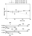
図3は、吐出口152、153の位置と基板Wの径方向の温度分布との関係を示す図である。グラフGa(Gb)は、ノズルユニット140a(140b)によって基板Wに温水51、52を吐出して基板Wの温度を調整したときの基板Wの径方向の温度分布の測定結果を示すグラフである。また、グラフGvは、基板Wの下面S2の周辺域K3に対して、温水51、52の吐出が行われない場合、すなわち、基板Wの中央域K1のみに温水を吐出した場合の、基板Wの径方向の温度分布をグラフGa、Gbとの比較のために示したものである。
<2. Regarding the position of the discharge port and the temperature distribution of the substrate W>
FIG. 3 is a diagram showing the relationship between the positions of the
ノズルユニット140aは、ノズル141a、142aを備えている。ノズル141aは、50℃に設定された温水51を吐出口151a、152aから基板Wの下面S2の中央域K1、中間域K2のそれぞれに吐出する。また、ノズル142aは、53℃に設定された温水52を吐出口153a、154aから基板Wの下面S2の中間域K2、周辺域K3のそれぞれに吐出する。同様に、ノズルユニット140bは、ノズル141b、142bを備えており、ノズル141bは、50℃に設定された温水51を吐出口151b、152bから基板Wの下面S2の中央域K1、中間域K2のそれぞれに吐出する。また、ノズル142bは、53℃に設定された温水52を吐出口153b、154bから基板Wの下面S2の中間域K2、周辺域K3のそれぞれに吐出する。
The
ノズルユニット140a(140b)の吐出口151a(151b)の中心軸は、基板Wの回転軸a1に一致している。また、回転軸a1から吐出口154aまでの径方向に沿った距離と、回転軸a1から吐出口154bまでの径方向に沿った距離とは互いに等しく、128mmである。
The central axis of the
ノズルユニット140aでは、基板Wの回転軸a1から吐出口152aまでの基板Wの径方向に沿った距離(第1距離)が、回転軸a1から吐出口153aまでの基板Wの径方向に沿った距離(第2距離)に比べて長い。具体的には、第1距離は75mmであり、第2距離は、50mmである。これに対して、ノズルユニット140bでは、基板Wの回転軸a1から吐出口152bまでの基板Wの径方向に沿った距離(第1距離)が、回転軸a1から吐出口153aまでの基板Wの径方向に沿った距離(第2距離)に比べて短い。具体的には、第1距離が50mmであり、第2距離が75mmである。
In the
図3に示されるように、グラフGvにおいて、基板Wの温度は、中心部分では、50℃であるが、測定位置が基板の周縁部分に近づくにつれて、徐々に低下している。具体的には、基板Wの周縁部の温度は、基板Wの中心部分の温度よりも3℃〜4℃低下している。 As shown in FIG. 3, in the graph Gv, the temperature of the substrate W is 50 ° C. in the central portion, but gradually decreases as the measurement position approaches the peripheral portion of the substrate. Specifically, the temperature of the peripheral portion of the substrate W is 3 ° C. to 4 ° C. lower than the temperature of the central portion of the substrate W.
グラフGaにおいては、基板Wの径方向における温度の測定位置に拘わらず、基板の温度が略50℃で安定している。これに対して、グラフGbにおいては、基板Wの中心から半径100mm以内の範囲では、基板Wの温度は、50℃以下であり、半径100mmから基板Wの周縁までの範囲では、基板Wの温度は、50℃以上となっている。なお、第1距離と第2距離とが同じになるように吐出口を設けた場合には、基板Wの径方向の位置に対する基板Wの温度分布のグラフは、グラフGaとグラフGbとの間を通るグラフとなる。 In the graph Ga, the temperature of the substrate is stable at about 50 ° C. regardless of the temperature measurement position in the radial direction of the substrate W. On the other hand, in the graph Gb, the temperature of the substrate W is 50 ° C. or less within a radius of 100 mm from the center of the substrate W, and the temperature of the substrate W is within a radius from 100 mm to the periphery of the substrate W. Is 50 ° C. or higher. When the discharge ports are provided so that the first distance and the second distance are the same, the graph of the temperature distribution of the substrate W with respect to the radial position of the substrate W is between the graph Ga and the graph Gb. The graph will pass through.
図4は、図3のノズルユニット140aにおいて、吐出口151aおよび152aから中央域K1および中間域K2に吐出される温水51の第1温度と、吐出口153aおよび154aから中間域K2および周辺域K3に吐出される温水52の第2温度とを種々に変更した場合の、基板Wの径方向における基板Wの温度分布をグラフ形式で示す図である。
4 shows the first temperature of the
グラフG1〜G3の何れについても、第1温度は50℃である。グラフG1〜G3についての第2温度は、53℃、58℃、63℃である。また、グラフG4〜G6の何れについても、第1温度は64℃である。また、グラフG1〜G3についての第2温度は、68℃、73℃、76℃である。 The first temperature is 50 ° C. for any of the graphs G1 to G3. The 2nd temperature about graph G1-G3 is 53 ° C, 58 ° C, and 63 ° C. Moreover, 1st temperature is 64 degreeC also about any of the graphs G4-G6. Moreover, the 2nd temperature about graph G1-G3 is 68 degreeC, 73 degreeC, and 76 degreeC.
グラフG1〜G6に示されるように、温水51の第1温度に拘わらず、第1温度と、温水52の第2温度との差が3℃〜4℃であれば、基板Wの径方向の温度は、第1温度近傍で安定している。第1温度と第2温度との差が8℃〜9℃、12℃〜13℃の何れにおいても、基板Wの周縁にゆくにつれて基板Wの温度が増加しており、温度差が8℃〜9℃の場合は、基板Wの周縁の方が中央よりも3℃ほど温度が高く、温度差が12℃〜13℃の場合は、基板Wの周縁の方が中央よりも6、7℃ほど温度が高い。
As shown in the graphs G <b> 1 to G <b> 6, regardless of the first temperature of the
図3、図4を参照しつつ上述したように、中間域K2に第1温度の温水51を吐出する吐出口の第1距離が、中間域K2に第2温度の温水52を吐出する第2距離と同じであるか、長い場合の方が、第1距離が第2距離よりも短い場合に比べて、基板Wの径方向に沿った基板Wの温度が第1温度の近傍において、より安定している。また、第1距離が第2距離よりも長い場合の方が、第1距離が第2距離と同じである場合に比べて、基板Wの径方向に沿った基板Wの温度が、第1温度の近傍においてより安定している。また、温水51が中央域K1だけでなく中間域K2にも吐出され、温水52が周辺域K3だけでなく中間域K2にも吐出されれば、第1距離と第2距離との関係に拘わらず、温水51が中央域K1のみに吐出され、温水52が周辺域K3のみに吐出される場合に比べて、基板Wの温度がより安定している。
As described above with reference to FIGS. 3 and 4, the first distance of the discharge port that discharges the
従って、温水51と温水52とが中間域K2に吐出されれば、第1距離が第2距離よりも短いとしても本発明の有用性を損なうものではないが、第1距離が第2距離に比べて、同じか、あるいは長くなるように設定されることが好ましい。さらには、第1距離が第2距離よりも長くなるように設定されることがより好ましい。
Therefore, if the
また、第1距離の方が、第2距離よりも長い場合において、温水51の第1温度と温水52の第2温度とは、第2温度が、第1温度よりも3℃〜4℃高くなるように、設定されることがより好ましい。
In addition, when the first distance is longer than the second distance, the first temperature of the
<3.基板処理装置の他の構成例>
図5、図6は、実施形態に係る基板処理装置の概略構成の他の例として、基板処理装置101、102の概略構成を模式的にそれぞれ示す図である。
<3. Other configuration examples of substrate processing apparatus>
FIG. 5 and FIG. 6 are diagrams each schematically showing a schematic configuration of
基板処理装置100では、温水供給源133から供給される第2温度の温水52に、水供給源132から供給される第1温度よりも低い温度の水50が混合されて第1温度の温水51が調製されていた。これに対して、図5に示す基板処理装置101では、温水51を貯留している温水供給源134が温水51を供給する。このように、基板処理装置101は、基板処理装置100の水供給源132、水供給源132に接続された各配管、および当該各配管に設けられた各開閉バルブに代えて、温水供給源134、温水供給源134に接続された各配管、および当該各配管に設けられた各開閉バルブを備えていることを除いて、基板処理装置100と同様の構成を備えており、同様の動作を行う。
In the
具体的には、温水供給源134と供給管181とは配管388によって接続されており、配管388の経路途中に、制御部161によって制御される開閉バルブ178が設けられている。これにより、基板処理装置101は、温水供給源134から配管388、供給管181を経て、ノズル141に温水51を供給する。また、温水供給源134は、配管387によって、配管アーム180の内部を挿通されてノズル120に接続された配管と接続されている。配管388の途中部には、制御部161によって制御される開閉バルブ177が設けられている。また、配管387の途中部には、原液供給源131から処理液53の原液を供給する配管381が接続されている。温水供給源134から供給される温水51に原液が混合されることにより、配管387の経路中において処理液53が調製され、処理液53は、ノズル120に接続された配管に供給される。
Specifically, the hot
また、図6に示す基板処理装置102は、基板処理装置101が備える温水供給源133、配管386、開閉バルブ176を備えておらず、温水供給源134と供給管182の下端とを接続する配管389と、配管389の経路途中に設けられたヒーター139と、開閉バルブ179とを備えていることを除いて、基板処理装置101と同様の構成を備えており、同様の動作を行う。
Further, the
具体的には、温水供給源134に貯留されている第1温度の温水51を配管389によって供給する過程で、基板処理装置102は、温水51をヒーター139によって第2温度に加熱し、開閉バルブ179と供給管182を経て温水52としてノズル142に供給する。
Specifically, in the process of supplying the
以上のような本実施形態に係る基板処理装置100、101、102の何れによっても、中間域K2に吐出された温水51、52は、基板Wの回転によって、混ざり合う。混ざり合った温度調整用流体の温度は第1温度と第2温度との間の温度となる。すなわち、第1温度の温水51と第2温度の温水52とを基板Wの下面S2に対して吐出することによって、吐出された後の、下面S2における温度調整用流体の温度を、中央域K1から周辺域K3にゆくにつれて高温になる少なくとも3段階の温度にすることができる。これにより、中央域K1から周辺域K3にゆくにつれて高温になるように予め温度制御した温度調整用流体を基板Wに吐出することなく、基板Wの温度を均一化できる。すなわち、基板処理装置の製造コストを抑制するとともに温度制御の複雑化を回避しつつ、基板Wの温度を均一化できる。
In any of the
また、以上のような本実施形態に係る基板処理装置100、101、102の何れによっても、ノズルユニット140は、中央域K1と中間域K2とに温水51を吐出するノズル141と、中間域K2と周辺域K3とに温水52を吐出するノズル142とを備える。これにより、ノズルの増加を抑制してノズルユニット140を小さくできるので、基板処理装置の製造コストを抑制できる。
Further, in any of the
また、以上のような本実施形態に係る基板処理装置100、101、102の何れによっても、ノズルユニット140は、中央域K2に温水51を吐出する吐出口151と、中間域K2に温水51を吐出する吐出口152とを備えるとともに、中間域K2に温水52を吐出する吐出口153と周辺域K3に温水52を吐出する吐出口154とを備える。これにより、吐出口の個数を低減してノズルユニット140の構造を簡略化できるので、基板処理装置の製造コストを抑制することができる。
Further, in any of the
また、以上のような本実施形態に係る基板処理装置によれば、中間域において、第2流体よりも低温の第1流体が、第2流体に比べて、基板中心からの基板径方向の距離が同じ位置か、あるいは当該距離がより長い位置に吐出される。これにより、当該距離がより短い位置に第1流体が吐出される場合に比べて基板温度を容易に均一化することができる。 Further, according to the substrate processing apparatus according to the present embodiment as described above, in the intermediate region, the first fluid having a temperature lower than the second fluid is a distance in the substrate radial direction from the substrate center as compared with the second fluid. Are discharged at the same position or at a position where the distance is longer. Thereby, compared with the case where the 1st fluid is discharged to the position where the said distance is shorter, substrate temperature can be equalized easily.
また、以上のような本実施形態に係る基板処理装置100、101、102の何れによっても、中間域K2において、温水52よりも低温の温水51が、温水52に比べて、基板Wの中心からの基板径方向の距離がより長い位置に吐出される。これにより、基板温度をさらに容易に均一化することができる。
Further, in any of the
また、以上のような本実施形態に係る基板処理装置100によれば、温水52に第1温度よりも低温の水50を混合することにより温水52が調製されるので、温水51用の温度調整機構が不要となり、基板処理装置の製造コストを抑制することができる。
Further, according to the
また、以上のような本実施形態に係る基板処理装置100、101、102の何れによっても、処理液53と温水51とは、略同じ温度に設定されている。従って、温水51および温水52の吐出によって温められた基板Wが、処理液53によって冷却されることを抑制できるので、基板Wの処理効率の低下を抑制できる。
In any of the
また、以上のような本実施形態に係る基板処理装置100、101、102の何れによっても、基板Wに供給される処理液53が温水51に基づいて調製されるので、処理液53と温水51との温度を別々に制御する場合に比べて簡略な温度制御によって処理液53と温水51とを略同じ温度に設定することができる。
Further, in any of the
本発明は詳細に示され記述されたが、上記の記述は全ての態様において例示であって限定的ではない。したがって、本発明は、その発明の範囲内において、実施の形態を適宜、変形、省略することが可能である。 Although the invention has been shown and described in detail, the above description is illustrative in all aspects and not restrictive. Therefore, embodiments of the present invention can be modified or omitted as appropriate within the scope of the invention.
100,101,102 基板処理装置
111 スピンチャック(基板保持部)
113 回転支軸
115 スピンベース
117 チャックピン
120 ノズル(処理液吐出部)
155 ノズル回転機構
140,140a,140b ノズルユニット(流体吐出部)
141,141a,141b,142,142a,142b ノズル
163 チャック回転機構(回転部)
180 配管アーム
50 水
51 温水(第1流体)
52 温水(第2流体)
53 処理液
K1 中央域
K2 中間域
K3 周辺域
L1 距離(第1距離)
L2 距離(第2距離)
S1 表面
S2 裏面
S3 周縁部
W 基板
100, 101, 102
113
155
141, 141a, 141b, 142, 142a,
180
52 Hot water (second fluid)
53 Treatment liquid K1 Central area K2 Intermediate area K3 Peripheral area L1 Distance (first distance)
L2 distance (second distance)
S1 surface S2 back surface S3 peripheral edge W substrate
Claims (7)
前記基板保持部に保持された前記基板を略水平面内にて回転させる回転部と、
前記回転部により回転されている前記基板の下面に第1温度以上の温度調整用流体を吐出する流体吐出部と、
前記温度調整用流体を吐出されている前記基板の上面に前記基板を処理するための処理液を吐出する処理液吐出部と、
を備え、
前記流体吐出部は、
前記温度調整用流体が前記第1温度に設定された第1流体を前記基板の下面の中央域に対して吐出する処理と、
前記温度調整用流体が前記第1温度よりも高い第2温度に設定された第2流体を前記基板の下面の周辺域に対して吐出する処理と、
前記第1流体と前記第2流体とを前記基板の下面における前記中央域と前記周辺域との間の中間域に対して吐出する処理と、
を並行して行い、
前記流体吐出部は、
前記中央域に前記第1流体を吐出する第1吐出口と、前記中間域に前記第1流体を吐出する第2吐出口とを備えるとともに、前記中間域に前記第2流体を吐出する第3吐出口と前記周辺域に前記第2流体を吐出する第4吐出口とを備え、
前記第2吐出口と前記基板中心との基板径方向に沿った第1距離が、前記第3吐出口と前記基板中心との基板径方向に沿った第2距離に比べて同じであるか、あるいは長い、基板処理装置。 A substrate holding unit for holding the substrate in a substantially horizontal posture;
A rotating unit that rotates the substrate held by the substrate holding unit in a substantially horizontal plane;
A fluid discharge unit that discharges a temperature adjusting fluid having a temperature equal to or higher than a first temperature to the lower surface of the substrate rotated by the rotation unit;
A processing liquid discharger for discharging a processing liquid for processing the substrate on the upper surface of the substrate from which the temperature adjusting fluid is discharged;
With
The fluid discharge part is
A process of discharging the first fluid whose temperature adjusting fluid is set to the first temperature to a central region of the lower surface of the substrate;
A process of discharging the second fluid, which is set to a second temperature higher than the first temperature, to the peripheral area of the lower surface of the substrate by the temperature adjusting fluid;
Discharging the first fluid and the second fluid to an intermediate region between the central region and the peripheral region on the lower surface of the substrate;
There line in parallel,
The fluid discharge part is
A third discharge port for discharging the first fluid to the intermediate region, and a first discharge port for discharging the first fluid to the central region; and a second discharge port for discharging the first fluid to the intermediate region. A discharge port and a fourth discharge port for discharging the second fluid to the peripheral area;
The first distance along the substrate radial direction between the second discharge port and the substrate center is the same as the second distance along the substrate radial direction between the third discharge port and the substrate center, Or a long substrate processing apparatus.
前記流体吐出部は、
前記基板の下方に設けられ、前記中央域と前記中間域とに前記第1流体を吐出する第1ノズルと、
前記基板の下方に設けられ、前記中間域と前記周辺域とに前記第2流体を吐出する第2ノズルと、
を備える、基板処理装置。 The substrate processing apparatus according to claim 1,
The fluid discharge part is
A first nozzle that is provided below the substrate and that discharges the first fluid to the central region and the intermediate region;
A second nozzle that is provided below the substrate and discharges the second fluid to the intermediate region and the peripheral region;
A substrate processing apparatus comprising:
前記第1距離が、前記第2距離に比べて長い、基板処理装置。 The substrate processing apparatus according to claim 1 or 2 , wherein
The substrate processing apparatus, wherein the first distance is longer than the second distance.
前記第2流体に前記第1温度よりも低温の前記温度調整用流体を混合することにより前記第1流体を調製する、基板処理装置。 A substrate processing apparatus according to any one of claims 1 to 3 , wherein
The substrate processing apparatus, wherein the first fluid is prepared by mixing the second fluid with the temperature adjusting fluid having a temperature lower than the first temperature.
前記処理液と前記第1流体とが略同じ温度に設定されている、基板処理装置。 A substrate processing apparatus according to any one of claims 1 to 4 , wherein
The substrate processing apparatus, wherein the processing liquid and the first fluid are set to substantially the same temperature.
前記温度調整用流体は液体であり、前記第1流体に基づいて前記処理液を調製する、基板処理装置。 A substrate processing apparatus according to any one of claims 1 to 5 , wherein
The substrate processing apparatus, wherein the temperature adjusting fluid is a liquid, and the processing liquid is prepared based on the first fluid.
前記温度調整用流体は、純水である、基板処理装置。 The substrate processing apparatus according to any one of claims of claims 1 to 6,
The substrate processing apparatus, wherein the temperature adjusting fluid is pure water.
Priority Applications (1)
| Application Number | Priority Date | Filing Date | Title |
|---|---|---|---|
| JP2013231733A JP6234174B2 (en) | 2013-11-08 | 2013-11-08 | Substrate processing equipment |
Applications Claiming Priority (1)
| Application Number | Priority Date | Filing Date | Title |
|---|---|---|---|
| JP2013231733A JP6234174B2 (en) | 2013-11-08 | 2013-11-08 | Substrate processing equipment |
Publications (2)
| Publication Number | Publication Date |
|---|---|
| JP2015092523A JP2015092523A (en) | 2015-05-14 |
| JP6234174B2 true JP6234174B2 (en) | 2017-11-22 |
Family
ID=53195541
Family Applications (1)
| Application Number | Title | Priority Date | Filing Date |
|---|---|---|---|
| JP2013231733A Expired - Fee Related JP6234174B2 (en) | 2013-11-08 | 2013-11-08 | Substrate processing equipment |
Country Status (1)
| Country | Link |
|---|---|
| JP (1) | JP6234174B2 (en) |
Family Cites Families (7)
| Publication number | Priority date | Publication date | Assignee | Title |
|---|---|---|---|---|
| JPS61102034A (en) * | 1984-10-25 | 1986-05-20 | Nec Corp | Method of developing photo-resist |
| JPH0536597A (en) * | 1991-07-26 | 1993-02-12 | Tokyo Electron Ltd | Treatment method |
| JPH07245287A (en) * | 1994-03-04 | 1995-09-19 | Fuji Xerox Co Ltd | Wet etching apparatus |
| JPH0837143A (en) * | 1994-07-25 | 1996-02-06 | Fuji Xerox Co Ltd | Semiconductor processing equipment |
| JPH10323606A (en) * | 1997-05-27 | 1998-12-08 | Dainippon Screen Mfg Co Ltd | Substrate processing equipment |
| JPH11165114A (en) * | 1997-12-05 | 1999-06-22 | Dainippon Screen Mfg Co Ltd | Single wafer substrate processing equipment |
| JP5123122B2 (en) * | 2008-09-11 | 2013-01-16 | 芝浦メカトロニクス株式会社 | Substrate processing apparatus and processing method |
-
2013
- 2013-11-08 JP JP2013231733A patent/JP6234174B2/en not_active Expired - Fee Related
Also Published As
| Publication number | Publication date |
|---|---|
| JP2015092523A (en) | 2015-05-14 |
Similar Documents
| Publication | Publication Date | Title |
|---|---|---|
| US10438821B2 (en) | Substrate processing apparatus | |
| US10026760B2 (en) | Substrate processing apparatus and substrate processing method | |
| TWI567853B (en) | Substrate processing apparatus and substrate processing method | |
| JP5249915B2 (en) | Chemical treatment apparatus and chemical treatment method | |
| JP5714449B2 (en) | Liquid processing apparatus, liquid processing method, and storage medium | |
| JP6336365B2 (en) | Substrate liquid processing equipment | |
| JP2013045972A5 (en) | ||
| JP6325919B2 (en) | Substrate processing apparatus and substrate processing method | |
| TW202113950A (en) | Etching apparatus and etching method | |
| JP2018147923A (en) | Substrate processing apparatus and substrate processing method | |
| JP6453168B2 (en) | Substrate processing equipment | |
| JP6285125B2 (en) | Method and apparatus for liquid processing of wafer-like articles | |
| TWI427438B (en) | Developing device, method for forming photoresist pattern, and memory medium | |
| WO2007035071A1 (en) | Apparatus and method for treating substrate | |
| JP6489475B2 (en) | Substrate processing equipment | |
| JP5661598B2 (en) | Substrate processing apparatus and substrate processing method | |
| JP5736017B2 (en) | Substrate processing method and substrate processing apparatus | |
| JP2015130542A (en) | Substrate processing method, and substrate processing apparatus | |
| JP6234174B2 (en) | Substrate processing equipment | |
| JP5832329B2 (en) | Substrate processing apparatus and substrate processing method | |
| JP2007088381A (en) | Device and method of processing substrate | |
| JP6376863B2 (en) | Substrate processing equipment | |
| JP6375160B2 (en) | Substrate processing method | |
| JP2008243935A (en) | Substrate processor and substrate processing method | |
| JP6812262B2 (en) | Substrate processing equipment and substrate processing method |
Legal Events
| Date | Code | Title | Description |
|---|---|---|---|
| A621 | Written request for application examination |
Free format text: JAPANESE INTERMEDIATE CODE: A621 Effective date: 20160608 |
|
| A977 | Report on retrieval |
Free format text: JAPANESE INTERMEDIATE CODE: A971007 Effective date: 20170309 |
|
| A131 | Notification of reasons for refusal |
Free format text: JAPANESE INTERMEDIATE CODE: A131 Effective date: 20170314 |
|
| A601 | Written request for extension of time |
Free format text: JAPANESE INTERMEDIATE CODE: A601 Effective date: 20170510 |
|
| A521 | Request for written amendment filed |
Free format text: JAPANESE INTERMEDIATE CODE: A523 Effective date: 20170626 |
|
| TRDD | Decision of grant or rejection written | ||
| A01 | Written decision to grant a patent or to grant a registration (utility model) |
Free format text: JAPANESE INTERMEDIATE CODE: A01 Effective date: 20171003 |
|
| A61 | First payment of annual fees (during grant procedure) |
Free format text: JAPANESE INTERMEDIATE CODE: A61 Effective date: 20171024 |
|
| R150 | Certificate of patent or registration of utility model |
Ref document number: 6234174 Country of ref document: JP Free format text: JAPANESE INTERMEDIATE CODE: R150 |
|
| LAPS | Cancellation because of no payment of annual fees |