JP6209801B2 - Pressure sensor - Google Patents
Pressure sensor Download PDFInfo
- Publication number
- JP6209801B2 JP6209801B2 JP2016553051A JP2016553051A JP6209801B2 JP 6209801 B2 JP6209801 B2 JP 6209801B2 JP 2016553051 A JP2016553051 A JP 2016553051A JP 2016553051 A JP2016553051 A JP 2016553051A JP 6209801 B2 JP6209801 B2 JP 6209801B2
- Authority
- JP
- Japan
- Prior art keywords
- resistance
- pressure sensor
- lever
- lever support
- resistance portion
- Prior art date
- Legal status (The legal status is an assumption and is not a legal conclusion. Google has not performed a legal analysis and makes no representation as to the accuracy of the status listed.)
- Active
Links
- 238000001514 detection method Methods 0.000 claims description 118
- 238000005192 partition Methods 0.000 claims description 47
- 238000006073 displacement reaction Methods 0.000 claims description 37
- 230000008859 change Effects 0.000 claims description 27
- 238000004891 communication Methods 0.000 claims description 11
- 239000004020 conductor Substances 0.000 claims description 8
- 230000005540 biological transmission Effects 0.000 claims description 7
- 230000004044 response Effects 0.000 claims description 2
- 238000000638 solvent extraction Methods 0.000 claims 1
- 230000035945 sensitivity Effects 0.000 description 70
- XUIMIQQOPSSXEZ-UHFFFAOYSA-N Silicon Chemical compound [Si] XUIMIQQOPSSXEZ-UHFFFAOYSA-N 0.000 description 13
- 229910052710 silicon Inorganic materials 0.000 description 13
- 239000010703 silicon Substances 0.000 description 13
- 238000012545 processing Methods 0.000 description 10
- 241001125929 Trisopterus luscus Species 0.000 description 9
- 238000000034 method Methods 0.000 description 9
- 239000000758 substrate Substances 0.000 description 8
- 238000004519 manufacturing process Methods 0.000 description 7
- 238000005452 bending Methods 0.000 description 6
- 238000010586 diagram Methods 0.000 description 6
- 230000003321 amplification Effects 0.000 description 5
- 238000003199 nucleic acid amplification method Methods 0.000 description 5
- 230000000694 effects Effects 0.000 description 4
- 238000012986 modification Methods 0.000 description 4
- 230000004048 modification Effects 0.000 description 4
- 230000002093 peripheral effect Effects 0.000 description 4
- 238000003860 storage Methods 0.000 description 4
- 230000007423 decrease Effects 0.000 description 3
- 238000009966 trimming Methods 0.000 description 3
- 238000013461 design Methods 0.000 description 2
- 239000004065 semiconductor Substances 0.000 description 2
- OAICVXFJPJFONN-UHFFFAOYSA-N Phosphorus Chemical compound [P] OAICVXFJPJFONN-UHFFFAOYSA-N 0.000 description 1
- VYPSYNLAJGMNEJ-UHFFFAOYSA-N Silicium dioxide Chemical compound O=[Si]=O VYPSYNLAJGMNEJ-UHFFFAOYSA-N 0.000 description 1
- 238000013459 approach Methods 0.000 description 1
- 230000015572 biosynthetic process Effects 0.000 description 1
- 239000011248 coating agent Substances 0.000 description 1
- 238000000576 coating method Methods 0.000 description 1
- 239000000470 constituent Substances 0.000 description 1
- 230000003111 delayed effect Effects 0.000 description 1
- 238000009792 diffusion process Methods 0.000 description 1
- 239000002019 doping agent Substances 0.000 description 1
- 238000010292 electrical insulation Methods 0.000 description 1
- 230000007613 environmental effect Effects 0.000 description 1
- 239000012535 impurity Substances 0.000 description 1
- 238000005468 ion implantation Methods 0.000 description 1
- 239000000463 material Substances 0.000 description 1
- 239000012528 membrane Substances 0.000 description 1
- 229910052698 phosphorus Inorganic materials 0.000 description 1
- 239000011574 phosphorus Substances 0.000 description 1
- 230000002265 prevention Effects 0.000 description 1
- 230000008569 process Effects 0.000 description 1
- 230000001681 protective effect Effects 0.000 description 1
- 229910052814 silicon oxide Inorganic materials 0.000 description 1
Images


Classifications
-
- G—PHYSICS
- G01—MEASURING; TESTING
- G01L—MEASURING FORCE, STRESS, TORQUE, WORK, MECHANICAL POWER, MECHANICAL EFFICIENCY, OR FLUID PRESSURE
- G01L9/00—Measuring steady of quasi-steady pressure of fluid or fluent solid material by electric or magnetic pressure-sensitive elements; Transmitting or indicating the displacement of mechanical pressure-sensitive elements, used to measure the steady or quasi-steady pressure of a fluid or fluent solid material, by electric or magnetic means
- G01L9/0001—Transmitting or indicating the displacement of elastically deformable gauges by electric, electro-mechanical, magnetic or electro-magnetic means
- G01L9/0002—Transmitting or indicating the displacement of elastically deformable gauges by electric, electro-mechanical, magnetic or electro-magnetic means using variations in ohmic resistance
-
- G—PHYSICS
- G01—MEASURING; TESTING
- G01L—MEASURING FORCE, STRESS, TORQUE, WORK, MECHANICAL POWER, MECHANICAL EFFICIENCY, OR FLUID PRESSURE
- G01L1/00—Measuring force or stress, in general
- G01L1/18—Measuring force or stress, in general using properties of piezo-resistive materials, i.e. materials of which the ohmic resistance varies according to changes in magnitude or direction of force applied to the material
-
- G—PHYSICS
- G01—MEASURING; TESTING
- G01L—MEASURING FORCE, STRESS, TORQUE, WORK, MECHANICAL POWER, MECHANICAL EFFICIENCY, OR FLUID PRESSURE
- G01L1/00—Measuring force or stress, in general
- G01L1/20—Measuring force or stress, in general by measuring variations in ohmic resistance of solid materials or of electrically-conductive fluids; by making use of electrokinetic cells, i.e. liquid-containing cells wherein an electrical potential is produced or varied upon the application of stress
- G01L1/22—Measuring force or stress, in general by measuring variations in ohmic resistance of solid materials or of electrically-conductive fluids; by making use of electrokinetic cells, i.e. liquid-containing cells wherein an electrical potential is produced or varied upon the application of stress using resistance strain gauges
- G01L1/2206—Special supports with preselected places to mount the resistance strain gauges; Mounting of supports
-
- G—PHYSICS
- G01—MEASURING; TESTING
- G01L—MEASURING FORCE, STRESS, TORQUE, WORK, MECHANICAL POWER, MECHANICAL EFFICIENCY, OR FLUID PRESSURE
- G01L1/00—Measuring force or stress, in general
- G01L1/20—Measuring force or stress, in general by measuring variations in ohmic resistance of solid materials or of electrically-conductive fluids; by making use of electrokinetic cells, i.e. liquid-containing cells wherein an electrical potential is produced or varied upon the application of stress
- G01L1/22—Measuring force or stress, in general by measuring variations in ohmic resistance of solid materials or of electrically-conductive fluids; by making use of electrokinetic cells, i.e. liquid-containing cells wherein an electrical potential is produced or varied upon the application of stress using resistance strain gauges
- G01L1/225—Measuring circuits therefor
- G01L1/2262—Measuring circuits therefor involving simple electrical bridges
-
- G—PHYSICS
- G01—MEASURING; TESTING
- G01L—MEASURING FORCE, STRESS, TORQUE, WORK, MECHANICAL POWER, MECHANICAL EFFICIENCY, OR FLUID PRESSURE
- G01L23/00—Devices or apparatus for measuring or indicating or recording rapid changes, such as oscillations, in the pressure of steam, gas, or liquid; Indicators for determining work or energy of steam, internal-combustion, or other fluid-pressure engines from the condition of the working fluid
- G01L23/08—Devices or apparatus for measuring or indicating or recording rapid changes, such as oscillations, in the pressure of steam, gas, or liquid; Indicators for determining work or energy of steam, internal-combustion, or other fluid-pressure engines from the condition of the working fluid operated electrically
- G01L23/10—Devices or apparatus for measuring or indicating or recording rapid changes, such as oscillations, in the pressure of steam, gas, or liquid; Indicators for determining work or energy of steam, internal-combustion, or other fluid-pressure engines from the condition of the working fluid operated electrically by pressure-sensitive members of the piezoelectric type
-
- G—PHYSICS
- G01—MEASURING; TESTING
- G01L—MEASURING FORCE, STRESS, TORQUE, WORK, MECHANICAL POWER, MECHANICAL EFFICIENCY, OR FLUID PRESSURE
- G01L9/00—Measuring steady of quasi-steady pressure of fluid or fluent solid material by electric or magnetic pressure-sensitive elements; Transmitting or indicating the displacement of mechanical pressure-sensitive elements, used to measure the steady or quasi-steady pressure of a fluid or fluent solid material, by electric or magnetic means
- G01L9/0001—Transmitting or indicating the displacement of elastically deformable gauges by electric, electro-mechanical, magnetic or electro-magnetic means
- G01L9/0008—Transmitting or indicating the displacement of elastically deformable gauges by electric, electro-mechanical, magnetic or electro-magnetic means using vibrations
- G01L9/0022—Transmitting or indicating the displacement of elastically deformable gauges by electric, electro-mechanical, magnetic or electro-magnetic means using vibrations of a piezoelectric element
-
- H—ELECTRICITY
- H10—SEMICONDUCTOR DEVICES; ELECTRIC SOLID-STATE DEVICES NOT OTHERWISE PROVIDED FOR
- H10D—INORGANIC ELECTRIC SEMICONDUCTOR DEVICES
- H10D48/00—Individual devices not covered by groups H10D1/00 - H10D44/00
- H10D48/50—Devices controlled by mechanical forces, e.g. pressure
Landscapes
- Physics & Mathematics (AREA)
- General Physics & Mathematics (AREA)
- Chemical & Material Sciences (AREA)
- Engineering & Computer Science (AREA)
- Combustion & Propulsion (AREA)
- Measuring Fluid Pressure (AREA)
- Pressure Sensors (AREA)
Description
本発明は、圧力センサに関する。
本願は、2014年10月6日に日本に出願された特願2014−205890号に基づき優先権を主張し、その内容をここに援用する。The present invention relates to a pressure sensor.
This application claims priority based on Japanese Patent Application No. 2014-205890 for which it applied to Japan on October 6, 2014, and uses the content here.
従来、圧力変動を検出する圧力センサ(差圧センサ)として、例えば、通気孔を有する収納容器と、収納容器内に配設され、透孔又は凹部を有する基板と、透孔内又は凹部内で振動可能に基板に片持ち支持された圧電素子と、を具備した圧力センサが知られている(特許文献1参照)。 Conventionally, as a pressure sensor (differential pressure sensor) for detecting pressure fluctuation, for example, a storage container having a vent, a substrate disposed in the storage container and having a through hole or a recess, and a through hole or a recess A pressure sensor including a piezoelectric element that is cantilevered on a substrate so as to vibrate is known (see Patent Document 1).
この圧力センサによれば、通気孔を介して収納容器内に伝わる圧力の変動と、この圧力の変動に遅れて追従する透孔又は凹部内部の圧力と、の差圧の大きさに応じて圧電素子が振動する。その結果、圧力センサは、圧電素子に生じる電圧変化に基づいて収納容器に伝わる圧力変動を検出することが可能とされる。 According to this pressure sensor, a piezoelectric is selected according to the magnitude of the pressure difference between the fluctuation of the pressure transmitted into the storage container through the vent hole and the pressure inside the through-hole or the recess following the fluctuation of the pressure. The element vibrates. As a result, the pressure sensor can detect a pressure fluctuation transmitted to the storage container based on a voltage change generated in the piezoelectric element.
ところで、上記従来の圧力センサの検出感度は、圧電素子の形状、透孔又は凹部の容積、透孔又は凹部と外気との間を出入りする流量等によって決定され、特に圧電素子の形状によって大きく左右され易い。しかしながら、圧電素子は、圧電体の両面に電極膜等を具備する両面電極構造とされているので、その構造上、厚みが増してしまい大きな変形量を確保することが難しい。従って、共振周波数を低下させつつ感度を増大させることが困難であり、例えば1Hz以下等の低周波帯域において所望の感度を確保することが難しいものであった。 By the way, the detection sensitivity of the conventional pressure sensor is determined by the shape of the piezoelectric element, the volume of the through-hole or the recess, the flow rate between the through-hole or the recess and the outside air, etc. It is easy to be done. However, since the piezoelectric element has a double-sided electrode structure including electrode films on both sides of the piezoelectric body, the thickness increases due to the structure, and it is difficult to ensure a large amount of deformation. Therefore, it is difficult to increase the sensitivity while lowering the resonance frequency, and it is difficult to ensure a desired sensitivity in a low frequency band such as 1 Hz or less.
本発明は、このような事情に考慮してなされたもので、その目的は、圧力変動の検出を精度良く行うことができると共に、圧力変動を感度良く検出することができる圧力センサを提供することである。 The present invention has been made in view of such circumstances, and an object of the present invention is to provide a pressure sensor that can accurately detect pressure fluctuations and can detect pressure fluctuations with high sensitivity. It is.
(1)本発明に係る圧力センサは、内部にキャビティが形成され、前記キャビティの内部と外部とを連通する連通開口が形成された中空のセンサ本体と、レバー本体と、前記レバー本体と前記センサ本体とを接続すると共に前記レバー本体を片持ち状態で支持する複数のレバー支持部と、を有し、前記連通開口を覆うように配置され、且つ前記キャビティと前記センサ本体の外部との圧力差に応じて撓み変形するカンチレバーと、前記センサ本体に形成された検出電極と、前記レバー本体に形成された本体抵抗部と、前記レバー支持部に形成されたレバー抵抗部と、を有し、前記本体抵抗部及び前記レバー抵抗部の抵抗値変化に基づいて前記カンチレバーの変位を検出する変位検出部と、を備え、前記レバー支持部には、前記レバー抵抗部を、前記検出電極に直列に電気接続される第1抵抗部と、該第1抵抗部よりも隣接する他の前記レバー支持部寄りに位置する第2抵抗部とに区画し、且つ前記第1抵抗部と前記第2抵抗部とを電気的に切り離す区画部が形成され、前記第1抵抗部は、前記本体抵抗部を経由した第1経路と、前記第2抵抗部を経由した第2経路と、の並列経路を介して前記検出電極に電気接続されていることを特徴とする。 (1) A pressure sensor according to the present invention includes a hollow sensor body in which a cavity is formed and a communication opening for communicating the inside and the outside of the cavity is formed, a lever body, the lever body, and the sensor A plurality of lever support portions for connecting the main body and supporting the lever main body in a cantilever state, arranged to cover the communication opening, and a pressure difference between the cavity and the outside of the sensor main body A cantilever that bends and deforms according to the sensor body, a detection electrode formed on the sensor body, a body resistance portion formed on the lever body, and a lever resistance portion formed on the lever support portion, A displacement detection unit that detects displacement of the cantilever based on a change in resistance value of the main body resistance unit and the lever resistance unit, and the lever support unit includes the lever resistance unit. The first resistor unit is divided into a first resistor unit electrically connected in series to the detection electrode and a second resistor unit positioned closer to the lever support unit adjacent to the first resistor unit. And a partition portion that electrically separates the second resistance portion from each other, and the first resistance portion includes a first path that passes through the main body resistance portion, a second path that passes through the second resistance portion, It is electrically connected to the detection electrode through a parallel path.
本発明に係る圧力センサによれば、センサ外部の圧力が変動すると、キャビティの内部と外部との間に圧力差が生じ、この圧力差に応じてカンチレバーが撓み変形する。この変形後、時間の経過と共に、カンチレバーと連通開口との隙間(ギャップ)を通じて圧力伝達媒体がキャビティの内部と外部との間を流動するので、キャビティの内部と外部との圧力が徐々に均衡状態となる。そのため、カンチレバーの撓みが徐々に小さくなり、最終的には元の状態に復元変形する。従って、変位検出部により、カンチレバーの変位(撓み変位)を検出することで、その検出結果から圧力変動を検出することができる。 According to the pressure sensor of the present invention, when the pressure outside the sensor fluctuates, a pressure difference is generated between the inside and the outside of the cavity, and the cantilever is bent and deformed according to the pressure difference. After this deformation, as the time passes, the pressure transmission medium flows between the inside and outside of the cavity through the gap between the cantilever and the communication opening, so the pressure inside and outside of the cavity is gradually balanced. It becomes. For this reason, the bending of the cantilever gradually decreases, and finally it is restored to its original state. Therefore, by detecting the displacement (deflection displacement) of the cantilever by the displacement detector, the pressure fluctuation can be detected from the detection result.
具体的に変位検出部は、レバー本体に形成された本体抵抗部及びレバー支持部に形成されたレバー抵抗部の抵抗値変化に基づいて、カンチレバーの変位を検出する。この際、レバー抵抗部は、区画部によって第1抵抗部と第2抵抗部とに区画されている。そして、第1抵抗部は、本体抵抗部を経由した第1経路と、第2抵抗部を経由した第2経路と、の並列経路を介して検出電極に電気接続されている。
従って、変位検出部は、第1経路の抵抗値変化、及び第2経路の抵抗値変化に基づいてカンチレバーの変位を検出する。Specifically, the displacement detection unit detects the displacement of the cantilever based on a resistance change of the body resistance part formed on the lever body and the lever resistance part formed on the lever support part. At this time, the lever resistance portion is divided into a first resistance portion and a second resistance portion by the partition portion. And the 1st resistance part is electrically connected to the detection electrode via the parallel path | route of the 1st path | route which passed along the main body resistance part, and the 2nd path | route via the 2nd resistance part.
Therefore, the displacement detection unit detects the displacement of the cantilever based on the resistance value change of the first path and the resistance value change of the second path.
ところで、カンチレバーは、レバー本体を片持ち状態で支持する複数のレバー支持部を中心に撓み変形するので、複数のレバー支持部はレバー本体よりも積極的に変位する。従って、感度に大きく寄与する応力検知部位は、レバー支持部における第1抵抗部及び第2抵抗部となる。これに対して、レバー本体における本体抵抗部は、感度への寄与度(貢献度)が小さい応力検知部位となる。 By the way, the cantilever is bent and deformed around a plurality of lever support portions that support the lever main body in a cantilever state, so that the plurality of lever support portions are displaced more positively than the lever main body. Accordingly, the stress detection parts that greatly contribute to the sensitivity are the first resistance part and the second resistance part in the lever support part. On the other hand, the main body resistance portion in the lever main body becomes a stress detection site with a small contribution to the sensitivity (contribution).
従って、区画部によってレバー抵抗部を第1抵抗部及び第2抵抗部に区画したうえで、第1抵抗部を、第1経路及び第2経路の並列経路を介して検出電極に電気接続することで、感度への貢献度が小さい本体抵抗部の影響をできるだけ小さくしつつ、感度に大きく寄与する第2抵抗部を積極的に利用することができる。
つまり、並列経路を構成することで、検出電極間の抵抗を下げ、検出電極間における全抵抗に対して第1抵抗部の抵抗比率を高めることができるので、感度を高くすることができる。Therefore, after dividing the lever resistance portion into the first resistance portion and the second resistance portion by the partition portion, the first resistance portion is electrically connected to the detection electrode via the parallel path of the first path and the second path. Thus, it is possible to positively use the second resistance portion that greatly contributes to the sensitivity while minimizing the influence of the main body resistance portion having a small contribution to the sensitivity.
That is, by configuring the parallel path, the resistance between the detection electrodes can be lowered, and the resistance ratio of the first resistance portion can be increased with respect to the total resistance between the detection electrodes, so that the sensitivity can be increased.
従って、感度良くカンチレバーの変位を検出することができる。これにより、センサ感度を向上でき、圧力変動の検出を精度良く行うことができる高性能な圧力センサとすることができる。その結果、例えば1Hz以下の低周波数帯域の圧力変動であっても感度良く検出することができ、検出できる下限周波数を下げることができる。 Therefore, the displacement of the cantilever can be detected with high sensitivity. Thereby, sensor sensitivity can be improved and it can be set as a high-performance pressure sensor which can detect a pressure fluctuation accurately. As a result, for example, pressure fluctuations in a low frequency band of 1 Hz or less can be detected with high sensitivity, and the lower limit frequency that can be detected can be lowered.
(2)前記区画部は、隣り合う前記レバー支持部にそれぞれ形成され、隣り合う前記レバー支持部の前記第1抵抗部同士は、前記本体抵抗部を経由した前記第1経路と、前記第2抵抗部及び前記カンチレバーの基端部側を経由した前記第2経路と、の並列経路により互いに電気接続された状態で前記検出電極に電気接続されても良い。 (2) The partition portions are respectively formed on the adjacent lever support portions, and the first resistance portions of the adjacent lever support portions are connected to the first path via the main body resistance portion, and the second You may electrically connect to the said detection electrode in the state mutually electrically connected by the parallel path | route with the said 2nd path | route via the resistance part and the base end part side of the said cantilever.
この場合には、変位検出部は、第1経路の抵抗値変化(一方のレバー支持部の第1抵抗部と、本体抵抗部と、他方のレバー支持部の第1抵抗部との抵抗値変化)、及び第2経路の抵抗値変化(一方のレバー支持部の第1抵抗部及び第2抵抗部と、他方のレバー支持部の第1抵抗部及び第2抵抗部との抵抗値変化)に基づいてカンチレバーの変位を検出する。 In this case, the displacement detector changes the resistance value of the first path (change of the resistance value of the first resistance part of one lever support part, the main body resistance part, and the first resistance part of the other lever support part. ) And a change in resistance value of the second path (resistance value change between the first resistance part and the second resistance part of one lever support part and the first resistance part and the second resistance part of the other lever support part) Based on this, the displacement of the cantilever is detected.
このように、隣り合うレバー支持部の第1抵抗部同士を、第1経路及び第2経路の2つの並列経路により電気接続することで、感度への貢献度が小さい本体抵抗部の影響をできるだけ小さくしつつ、感度に大きく寄与する第2抵抗部を積極的に利用することができる。つまり、このように並列経路を構成することで、検出電極間の抵抗を下げ、検出電極間における全抵抗に対して第1抵抗部の抵抗比率を高めることができるので、感度を高くすることができる。 In this way, by electrically connecting the first resistance portions of the adjacent lever support portions by the two parallel paths of the first path and the second path, the influence of the main body resistance section having a small contribution to the sensitivity can be minimized. The second resistance portion that greatly contributes to sensitivity can be positively utilized while being reduced. That is, by configuring the parallel path in this way, the resistance between the detection electrodes can be lowered, and the resistance ratio of the first resistance portion can be increased with respect to the total resistance between the detection electrodes, so that the sensitivity can be increased. it can.
特に、隣り合うレバー支持部の第1抵抗部同士を、第1経路及び第2経路の並列経路により電気接続しているので、これら両経路の工夫により感度向上に向けて複数の手法を選択することが可能である。
例えば、第2経路側の工夫により検出電極に直列に接続される第1抵抗部の影響をできるだけ大きくすることで、検出電極間における全抵抗に対して第1抵抗部の抵抗比率を高め、それにより感度を高めることが可能である。または、第1経路側の工夫により本体抵抗部の抵抗値を上げることで、感度に大きく寄与する第2抵抗部の影響をより大きくして、第1抵抗部同士を電気接続している並列経路部分の感度を高くし、その結果、検出電極間の全体の感度を高めることが可能である。
このように、感度向上に向けて複数の手法を選択することができるので、設計の自由度を高めることができ、各種の用途に利用し易い圧力センサとすることができる。In particular, since the first resistance portions of the adjacent lever support portions are electrically connected by a parallel path of the first path and the second path, a plurality of methods are selected for improving sensitivity by devising these paths. It is possible.
For example, by increasing the influence of the first resistance part connected in series to the detection electrode as much as possible by devising the second path side, the resistance ratio of the first resistance part is increased with respect to the total resistance between the detection electrodes. It is possible to increase sensitivity. Or the parallel path which electrically connects the 1st resistance parts by making the influence of the 2nd resistance part which contributes greatly to a sensitivity increase by raising the resistance value of a main part resistance part by the device by the 1st path side It is possible to increase the sensitivity of the part and, as a result, increase the overall sensitivity between the detection electrodes.
As described above, since a plurality of methods can be selected for improving sensitivity, the degree of freedom in design can be increased, and a pressure sensor that can be easily used for various applications can be obtained.
(3)前記区画部は、前記レバー支持部の支持幅に沿った前記第1抵抗部の第1幅が、前記レバー支持部の支持幅に沿った前記第2抵抗部の第2幅よりも幅狭となるように、前記第1抵抗部及び前記第2抵抗部を区画しても良い。 (3) In the partition portion, the first width of the first resistance portion along the support width of the lever support portion is larger than the second width of the second resistance portion along the support width of the lever support portion. You may partition the said 1st resistance part and the said 2nd resistance part so that it may become narrow.
この場合には、第1抵抗部の抵抗値を第2抵抗部の抵抗値よりも大きくすることができるので、検出電極間における全抵抗に対して、検出電極に直列に接続される第1抵抗部の抵抗比率をさらに高めることができる。従って、センサ感度をより向上することができる。 In this case, since the resistance value of the first resistance portion can be made larger than the resistance value of the second resistance portion, the first resistance connected in series to the detection electrodes with respect to the total resistance between the detection electrodes. The resistance ratio of the part can be further increased. Therefore, the sensor sensitivity can be further improved.
(4)前記区画部は、前記レバー抵抗部に溝状に形成された区画溝であっても良い。 (4) The partition portion may be a partition groove formed in the lever resistance portion in a groove shape.
この場合には、例えばレバー抵抗部を形成した後に、溝加工等により区画溝を形成することで、第1抵抗部及び第2抵抗部を確実に電気的に切り離した状態で容易に形成することができる。従って、圧力センサをより効率良く製造し易い。 In this case, for example, the first resistance portion and the second resistance portion can be easily formed in a state where the first resistance portion and the second resistance portion are electrically separated from each other by, for example, forming a partition groove by groove processing after forming the lever resistance portion. Can do. Therefore, it is easy to manufacture the pressure sensor more efficiently.
(5)前記第2抵抗部には、前記第1抵抗部よりも電気抵抗率が小さい導電体が形成されていても良い。 (5) A conductor having an electrical resistivity smaller than that of the first resistor may be formed in the second resistor.
この場合には、第2抵抗部の抵抗値を第1抵抗部の抵抗値よりも小さくすることができるので、相対的に第1抵抗部の抵抗値を大きくして、検出電極間における全抵抗に対して、第1抵抗部の抵抗比率をさらに高めることができる。従って、センサ感度をさらに向上することができる。 In this case, since the resistance value of the second resistance portion can be made smaller than the resistance value of the first resistance portion, the resistance value of the first resistance portion is relatively increased so that the total resistance between the detection electrodes is increased. In contrast, the resistance ratio of the first resistance portion can be further increased. Therefore, the sensor sensitivity can be further improved.
(6)前記本体抵抗部には、該本体抵抗部の抵抗を増大させる抵抗増大部が形成されていても良い。 (6) A resistance increasing portion that increases the resistance of the main body resistance portion may be formed in the main body resistance portion.
この場合には、レバー本体における本体抵抗部の抵抗値を大きくすることができるので、第1経路よりも第2経路をさらに優先的に利用でき、感度に大きく寄与する第2抵抗部の影響をより大きくすることができる。これにより、例えば第1抵抗部同士を電気接続している並列経路部分の感度を高くすることができ、検出電極間の全体の感度を高めることができる。その結果、センサ感度をさらに向上することができる。 In this case, since the resistance value of the main body resistance portion in the lever main body can be increased, the second path can be used more preferentially than the first path, and the influence of the second resistance section that greatly contributes to the sensitivity can be achieved. Can be larger. Thereby, the sensitivity of the parallel path | route part which electrically connected 1st resistance parts can be made high, for example, and the whole sensitivity between detection electrodes can be raised. As a result, sensor sensitivity can be further improved.
(7)前記抵抗増大部は、前記本体抵抗部に溝状に形成され、且つ前記本体抵抗部を流れる電流の送電距離を増大させるように形成された溝部であっても良い。 (7) The resistance increasing portion may be a groove portion that is formed in a groove shape in the main body resistance portion and is formed so as to increase a power transmission distance of a current flowing through the main body resistance portion.
この場合には、前記本体抵抗部を流れる電流の送電距離を増大できるので、その分だけ本体抵抗部の抵抗値を大きくすることができる。また、例えば本体抵抗部を形成した後に、溝加工等により溝部を容易に形成できるので、圧力センサの製造効率を向上し易い。 In this case, since the transmission distance of the current flowing through the main body resistance portion can be increased, the resistance value of the main body resistance portion can be increased accordingly. Further, for example, after forming the main body resistance portion, the groove portion can be easily formed by groove processing or the like, so that it is easy to improve the manufacturing efficiency of the pressure sensor.
(8)前記抵抗増大部は、前記本体抵抗部に溝状に形成され、且つ前記本体抵抗部を流れる電流の流れを妨げるように形成された溝部であっても良い。 (8) The resistance increasing portion may be a groove portion that is formed in a groove shape in the main body resistance portion, and is formed so as to prevent a current flow through the main body resistance portion.
この場合には、前記本体抵抗部を流れる電流の流れを妨げることができるので、その分だけ本体抵抗部の抵抗値を大きくすることができる。また、例えば本体抵抗部を形成した後に、溝加工等により溝部を容易に形成できるので、圧力センサの製造効率を向上し易い。 In this case, since the flow of current flowing through the main body resistance portion can be prevented, the resistance value of the main body resistance portion can be increased accordingly. Further, for example, after forming the main body resistance portion, the groove portion can be easily formed by groove processing or the like, so that it is easy to improve the manufacturing efficiency of the pressure sensor.
(9)前記抵抗増大部は、絶縁層であっても良い。 (9) The resistance increasing portion may be an insulating layer.
この場合には、本体抵抗部に例えば機械的加工によって抵抗増大のための溝加工や孔加工を施す必要がなく、半導体製造技術等を利用して絶縁層を形成すれば良いので、機械的加工によるカンチレバーの剛性低下を防ぐことができ、より高品質な圧力センサにし易い。また、機械的加工が不要となるので、圧力センサの製造効率を向上することができる。 In this case, it is not necessary to perform groove processing or hole processing for increasing resistance by, for example, mechanical processing on the main body resistance portion, and it is only necessary to form an insulating layer using a semiconductor manufacturing technique or the like. Can prevent the cantilever from being lowered in rigidity, and it is easy to make a pressure sensor of higher quality. Further, since mechanical processing is not necessary, the manufacturing efficiency of the pressure sensor can be improved.
(10)前記カンチレバーの基端部側には、隣り合う前記レバー支持部の間に形成された基端抵抗部と、前記基端抵抗部の抵抗を調整する抵抗調整部と、が設けられていても良い。 (10) On the base end portion side of the cantilever, a base end resistance portion formed between adjacent lever support portions and a resistance adjustment portion that adjusts the resistance of the base end resistance portion are provided. May be.
この場合には、基端抵抗部の抵抗(電気抵抗値)を調整できるので、感度に大きく寄与する第2抵抗部の抵抗比率を調整することができる。そのため、例えば検出電極に直列に電気接続される第1抵抗部の影響が大きくなるように調整して、検出電極間における全抵抗に対する第1抵抗部の抵抗比率を高めてセンサ感度を向上させることが可能である。或いは、第2抵抗部の影響が大きくなるように調整して、第2経路全体の感度を高くして、検出電極間の全体の感度を向上させることも可能である。
このように、例えば第1経路及び第2経路の2つの並列経路により互いに電気接続された第1抵抗部同士間における全体の電気抵抗値を調整することができる。従って、感度調整だけでなく、例えば変位検出部が有するブリッジ回路に対するバランス調整等を行うことができる。In this case, since the resistance (electric resistance value) of the base end resistance portion can be adjusted, the resistance ratio of the second resistance portion that greatly contributes to the sensitivity can be adjusted. Therefore, for example, by adjusting so that the influence of the first resistance portion electrically connected in series to the detection electrode is increased, the resistance ratio of the first resistance portion to the total resistance between the detection electrodes is increased to improve the sensor sensitivity. Is possible. Alternatively, it is possible to increase the sensitivity of the entire second path by adjusting the influence of the second resistance portion so as to increase the sensitivity of the entire detection electrode.
Thus, for example, it is possible to adjust the overall electrical resistance value between the first resistance portions that are electrically connected to each other through two parallel paths, for example, the first path and the second path. Accordingly, not only the sensitivity adjustment but also the balance adjustment for the bridge circuit of the displacement detection unit, for example, can be performed.
(11)前記センサ本体の外部に露出するように配置されると共に、レファレンス抵抗部が形成されたレファレンス部を備え、前記変位検出部は、前記本体抵抗部及び前記レバー抵抗部の抵抗値変化と、前記レファレンス抵抗部の抵抗値変化との差分に基づいて前記カンチレバーの変位を検出しても良い。 (11) It is arranged so as to be exposed to the outside of the sensor main body, and includes a reference portion in which a reference resistance portion is formed, and the displacement detection portion includes a resistance value change of the main body resistance portion and the lever resistance portion. The displacement of the cantilever may be detected based on a difference from a change in resistance value of the reference resistance portion.
この場合には、温度変化等の環境変化や振動等の外乱に起因する感度変動を相殺することができ、圧力変動の検出をさらに高精度に行うことができる。 In this case, sensitivity fluctuations caused by environmental changes such as temperature changes and disturbances such as vibration can be canceled out, and pressure fluctuations can be detected with higher accuracy.
本発明に係る圧力センサによれば、圧力変動の検出を精度良く行うことができると共に、圧力変動を感度良く検出することができる。 According to the pressure sensor of the present invention, pressure fluctuation can be detected with high accuracy, and pressure fluctuation can be detected with high sensitivity.
(第1実施形態)
以下、本発明に係る圧力センサの第1実施形態について図面を参照して説明する。(First embodiment)
Hereinafter, a first embodiment of a pressure sensor according to the present invention will be described with reference to the drawings.
図1〜3に示すように、本実施形態の圧力センサ1は、所定の周波数帯域の圧力変動を検出するセンサであり、圧力伝達媒体(例えば空気等の気体)が存在する空間等に配置されて使用される。
圧力センサ1は、例えばSOI基板5を利用して形成された直方体状の外形を有するセンサ本体2と、先端部3aが自由端とされ、基端部3bが片持ち支持されたカンチレバー3と、カンチレバー3の変位(撓み変位)を検出する変位検出部4と、を備えている。As shown in FIGS. 1-3, the
The
なお、本実施形態では、圧力センサ1の厚み方向に沿ったカンチレバー3側を上方、その反対側を下方といい、圧力センサ1の平面視で縦方向(長手方向)をL1(以下、縦方向L1)、圧力センサ1の平面視で縦方向L1に直交する横方向(短手方向)をL2(以下、横方向L2)という。
また、SOI基板5は、シリコン支持層5a、シリコン酸化膜等の電気的絶縁性を有する酸化層5b、及びシリコン活性層5cを熱的に張り合わせた基板とされている。In the present embodiment, the
The
センサ本体2は、例えばSOI基板5におけるシリコン支持層5aで形成されている。具体的には、センサ本体2は底壁部2a及び周壁部2bを有し、上方に開口する中空の有底筒状に形成されている。センサ本体2の内部空間は、キャビティ(空気室)10として機能し、上方に開口した部分がキャビティ10の内部と外部とを連通する連通開口11として機能する。
The
酸化層5bは、センサ本体2の周壁部2bの開口端縁上に全周に亘って環状に形成されている。シリコン活性層5cは、センサ本体2を上方から塞ぐように酸化層5b上に形成されている。このシリコン活性層5cには、該シリコン活性層5cを厚さ方向に貫通する平面視コ形状(C形状)のギャップ12が形成されている。これにより、シリコン活性層5cには、環状の枠部13とカンチレバー3とが形成されている。
The oxide layer 5 b is formed in an annular shape over the entire circumference on the opening edge of the
上記ギャップ12は、平面視で連通開口11の内側に位置する領域内(キャビティ10の内部に連通する領域内)に形成され、そのギャップ幅Gは、例えば数百nm〜数十μmの微小幅とされている。
The
カンチレバー3は、基端部3bが枠部13を介してセンサ本体2における周壁部2bの開口端の内側に一体的に接続され、且つ先端部3aが自由端とされた片持ち梁構造とされ、連通開口11を覆うように配置されている。
なお、枠部13は、酸化層5b上に全周に亘って環状に形成されていると共に、一部が連通開口11を覆うように周壁部2bよりもカンチレバー3側に突出している。これにより、枠部13の一部は連通開口11を覆っている。The
The
カンチレバー3について詳細に説明する。
カンチレバー3は、レバー本体20と、該レバー本体20を片持ち状態で支持する2つのレバー支持部21A、21Bと、を備えている。そして、カンチレバー3は、基端部3bを中心としてキャビティ10の内部と外部との圧力差(すなわち、ギャップ12を介してキャビティ10の内部と外部との間を流通可能な圧力伝達媒体による圧力の差)に応じて撓み変形する。The
The
カンチレバー3の基端部3bには、該カンチレバー3を厚さ方向に貫通する平面視コ形状(C形状)の補助ギャップ22が形成されている。この補助ギャップ22は、カンチレバー3の基端部3bにおいて圧力センサ1の横方向L2の中央部に配置されている。これにより、カンチレバー3は基端部3bを中心として撓み変形し易い構造とされている。
The
2つのレバー支持部21A、21Bは、補助ギャップ22を挟んで横方向L2に並ぶように配置され、レバー本体20と枠部13とを接続すると共にレバー本体20を片持ち状態で支持している。従って、カンチレバー3は、これらレバー支持部21A、21Bを中心に撓み変形する。
なお、2つのレバー支持部21A、21Bの横方向L2に沿った支持幅は、同等とされている。従って、カンチレバー3が撓み変形した際、一方のレバー支持部21Aに作用する単位面積当たりの応力と、他方のレバー支持部21Bに作用する単位面積当たりの応力とは同等とされている。The two
The support widths along the lateral direction L2 of the two
上述したカンチレバー3及び枠部13が形成されたシリコン活性層5cには、ピエゾ抵抗(抵抗素子)30がシリコン活性層5cの全面に亘って形成されている。このピエゾ抵抗30は、例えばリン等のドープ剤(不純物)がイオン注入法や拡散法等の各種の方法によりドーピングされることで形成されている。
In the silicon
ピエゾ抵抗30のうち、レバー本体20に形成されている部分は、レバー本体20の撓み量に応じて抵抗値が変化する本体抵抗部31として機能する。また、ピエゾ抵抗30のうち、レバー支持部21A、21Bに形成されている部分は、レバー支持部21A、21Bの撓み量に応じて抵抗値が変化するレバー抵抗部32として機能する。さらに、ピエゾ抵抗30のうち、カンチレバー3の基端部3b側であって2つのレバー支持部21A、21Bの間に形成されている部分は、基端抵抗部33として機能する。
A portion of the
さらに、ピエゾ抵抗30の上面には、ピエゾ抵抗30よりも電気抵抗率が小さい導電性材料(例えばAU等)からなる検出電極35が形成されている。この検出電極35は、平面視でカンチレバー3を囲む枠状に形成され、枠部13の上方に配置されている。
なお、ピエゾ抵抗30及び検出電極35の上面に図示しない絶縁膜を保護膜として被膜することで、外部との電気的な接触を防止することが好ましい。Further, on the upper surface of the
Note that it is preferable to prevent electrical contact with the outside by coating an insulating film (not shown) as a protective film on the upper surfaces of the
レバー支持部21A、21Bには、上記レバー抵抗部32を第1抵抗部32aと第2抵抗部32bとに区画し、これら第1抵抗部32aと第2抵抗部32bとを電気的に切り離す区画溝(区画部)40が形成されている。
ここで、一方のレバー支持部21Aに形成された区画溝40について詳細に説明する。In the
Here, the
区画溝40は、レバー支持部21Aにおける横方向L2の中央部分に配置され、縦方向L1に沿って延びた直線状に形成されている。この際、区画溝40は、レバー支持部21Aにおける縦方向L1の中間部から、カンチレバー3の基端部3bに向かって直線状に延びると共に、検出電極35を横方向L2に分断するようにセンサ本体2の側方まで達するように形成されている。
The
このように区画溝40が形成されているので、レバー抵抗部32は横方向L2に区画され、上記第1抵抗部32aと、第1抵抗部32aよりも他方のレバー支持部21B寄りに位置する上記第2抵抗部32bとに電気的に切り離されている。
また、レバー支持部21Aにおける横方向L2の中央部分に区画溝40が配置されているので、横方向L2に沿った第1抵抗部32aの第1幅W1と、横方向L2に沿った第2抵抗部32bの第2幅W2とは同等のサイズとされている。Since the
Further, since the
なお、図示の例では、区画溝40は酸化層5bに達する深さとされている。但し、この場合に限られるものではなく、例えばカンチレバー3を厚さ方向に貫通しても良い。いずれにしても、少なくとも酸化層5bに達する深さまで区画溝40を形成することが好ましい。さらに、区画溝40は、レバー支持部21Aにおける縦方向L1の中間部よりも、レバー本体20側に向けてさらに延びていても構わない。
In the illustrated example, the
他方のレバー支持部21Bについても、上述と同様に区画溝40が形成されている。従って、他方のレバー支持部21Bにおけるレバー抵抗部32は、区画溝40によって、第1抵抗部32aと、第1抵抗部32aよりも一方のレバー支持部21A寄りに位置する第2抵抗部32bと、に電気的に切り離されている。
A
ところで、2つのレバー支持部21A、21Bに形成された区画溝40は、上述したようにそれぞれ検出電極35を横方向L2に分断するようにセンサ本体2の側方まで達するように形成されている。従って、検出電極35は、これら区画溝40を挟んで横方向L2に電気的に切り離されている。
By the way, the
検出電極35のうち、一方のレバー支持部21Aにおける第1抵抗部32a側に位置する部分は、第1抵抗部32aに直列に電気接続される第1検出電極35Aとして機能する。また、検出電極35のうち、他方のレバー支持部21Bにおける第1抵抗部32a側に位置する部分は、第1抵抗部32aに直列に電気接続される第2検出電極35Bとして機能する。
Of the
また、枠部13には、カンチレバー3の先端部3a側に位置する部分に、第1検出電極35Aと第2検出電極35Bとを電気的に切り離す電極溝41が形成されている。この電極溝41は、ギャップ12とセンサ本体2の側方との間に亘って縦方向L1に沿って延びた直線状に形成され、例えば酸化層5bに達する深さとされている。
In addition, an
このように電気的に切り離された第1検出電極35A及び第2検出電極35Bには、本体抵抗部31及びレバー抵抗部32の抵抗値変化に基づいてカンチレバー3の変位を検出する検出回路50が接続されている。
これにより、検出回路50を通じて、第1検出電極35A及び第2検出電極35B間に所定電圧が印加されると、この電圧印加に起因する電流は、第1検出電極35Aから一方のレバー支持部21Aの第1抵抗部32a及び他方のレバー支持部21Bの第1抵抗部32aを経由して、第2検出電極35Bに流れる。The
Accordingly, when a predetermined voltage is applied between the
従って、検出回路50は、第1検出電極35A及び第2検出電極35B間における全体の電気抵抗値Rの変化を、カンチレバー3の変位(撓み変形に伴う変位)に応じて変化する電気的な出力信号(センサ信号)として取り出すことが可能とされている。従って、この出力信号に基づいてカンチレバー3の変位を検出でき、圧力変動を検出することが可能となる。
Therefore, the
よって、上述した検出電極35、本体抵抗部31、レバー抵抗部32及び検出回路50は、第1検出電極35A及び第2検出電極35B間における電気抵抗値Rの抵抗値変化に基づいてカンチレバー3の変位を検出する変位検出部4として機能する。
Therefore, the
特に、2つのレバー支持部21A、21Bにおけるレバー抵抗部32は、それぞれ第1抵抗部32a及び第2抵抗部32bに区画されている。
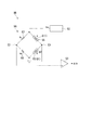
従って、図4に示すように、2つのレバー支持部21A、21Bの第1抵抗部32a同士は、本体抵抗部31を経由した第1経路S1と、第2抵抗部32b及び基端抵抗部33を経由した第2経路S2と、の並列経路により互いに電気接続されている。
従って、第1検出電極35A及び第2検出電極35B間における上記電気抵抗値Rは、下記の式1で表される。In particular, the
Therefore, as shown in FIG. 4, the
Therefore, the electrical resistance value R between the
なお、一方のレバー支持部21Aにおける第1抵抗部32aに着目すると、第1経路S1及び第2経路S2の並列経路を介して、第1検出電極35Aと第2検出電極35Bとの間に電気接続された状態にもなっている。他方のレバー支持部21Bにおける第1抵抗部32aについても同様である。
When attention is paid to the

式1において、R1は一方のレバー支持部21Aにおける第1抵抗部32aの電気抵抗値を示す。R2は一方のレバー支持部21Aにおける第2抵抗部32bの電気抵抗値を示す。R3は他方のレバー支持部21Bにおける第2抵抗部32bの電気抵抗値を示す。R4は他方のレバー支持部21Bにおける第1抵抗部32aの電気抵抗値を示す。R5は本体抵抗部31の電気抵抗値を示す。R6は基端抵抗部33の電気抵抗値を示す。
In
なお、レバー支持部21A、21Bにおける第1抵抗部32aは、第1検出電極35A及び第2検出電極35Bに対して直列に接続されているので、式1から明らかなように、電気抵抗値(R1、R4)が変化すると、全体の電気抵抗値Rの変化に大きく影響を与え易い。
In addition, since the
上記検出回路50は、図5に示すように、ブリッジ回路(ホイートストンブリッジ回路)51と、基準電圧発生回路52と、作動増幅回路53と、を備えている。
As shown in FIG. 5, the
ブリッジ回路51は、カンチレバー3全体のセンサ抵抗55及び第1固定抵抗56が直列接続された枝辺と、第2固定抵抗57及び第3固定抵抗58が直列接続された枝辺と、が基準電圧発生回路52に対して並列に接続されている。
なお、センサ抵抗55の電気抵抗値は上述した電気抵抗値Rである。各固定抵抗56、57、58の電気抵抗値は、それぞれ電気抵抗値Rb、Rc、Rdとされている。The
The electric resistance value of the
ブリッジ回路51において、センサ抵抗55と第1固定抵抗56との接続点(中点電圧E1)は、作動増幅回路53の反転入力端子(−端子)に接続され、第2固定抵抗57と第3固定抵抗58との接続点(中点電圧E2)は、作動増幅回路53の非反転入力端子(+端子)に接続されている。
In the
基準電圧発生回路52は、ブリッジ回路51に対して所定の基準電圧Vccを印加する。作動増幅回路53は、中点電圧E1と中点電圧E2との間の電位差を検出し、この電位差を所定増幅率にて増幅して出力する。この電位差は、電気抵抗値Rの変化に応じた値、すなわちカンチレバー3の変位に基づいた値となる。
The reference
(圧力センサの作動)
次に、上述した圧力センサ1を利用して、圧力変動を検出する場合について説明する。(Pressure sensor operation)
Next, a case where pressure fluctuation is detected using the
はじめに、図6に示す時刻t1以前の期間Aのように、キャビティ10の外部の圧力(以下、外気圧Poutと称する)と、キャビティ10の内部の圧力(以下、内気圧Pinと称する)との圧力差がゼロである場合には、図7Aに示すように、カンチレバー3は撓み変形しない。これにより、検出回路50から出力される出力信号(センサ信号)は所定値(例えばゼロ)である。
First, as in the period A before time t1 shown in FIG. 6, the pressure outside the cavity 10 (hereinafter referred to as the external pressure Pout) and the pressure inside the cavity 10 (hereinafter referred to as the internal pressure Pin). When the pressure difference is zero, the
そして、図6に示す時刻t1以降の期間Bのように、例えば外気圧Poutがステップ状に上昇すると、キャビティ10の外部と内部との間に圧力差が生じるので、図7Bに示すようにカンチレバー3はキャビティ10の内部に向けて撓み変形する。
すると、カンチレバー3の撓み変形に応じて、レバー本体20に形成された本体抵抗部31、及びレバー支持部21A、21Bに形成されたレバー抵抗部32に歪が生じ、それにより全体の電気抵抗値Rが変化するので、図6に示すように出力信号が増大する。Then, as in the period B after time t1 shown in FIG. 6, for example, when the external air pressure Pout rises stepwise, a pressure difference is generated between the outside and the inside of the
Then, according to the bending deformation of the
さらに、外気圧Poutの上昇以降、ギャップ12を介してキャビティ10の外部から内部へと圧力伝達媒体が流動するので、図6に示すように、内気圧Pinが時間の経過と共に外気圧Poutよりも遅れながら、且つ外気圧Poutの変動よりも緩やかな応答で上昇する。
これにより、内気圧Pinが外気圧Poutに徐々に近づくので、キャビティ10の外部と内部との圧力が均衡状態になりはじめ、カンチレバー3の撓みが徐々に小さくなり、図6に示すように出力信号が徐々に低下する。Furthermore, since the pressure transmission medium flows from the outside to the inside of the
As a result, the internal pressure Pin gradually approaches the external pressure Pout, so that the pressure between the outside and the inside of the
そして、内気圧Pinが外気圧Poutに等しくなると、図7Cに示すように、カンチレバー3の撓み変形が解消されて元の状態に復帰し、図6に示す時刻t2以降の期間Cのように出力信号が再び所定値(例えばゼロ)になる。
When the internal pressure Pin becomes equal to the external pressure Pout, as shown in FIG. 7C, the bending deformation of the
このように、変位検出部4により、カンチレバー3の変位に基づいた出力信号の変動をモニタすることで、圧力変動を検出することができる。
特に、SOI基板5のシリコン活性層5cを利用して半導体プロセス技術によりカンチレバー3を形成できるので、従来の圧電素子に比べて薄型化(例えば数十〜数百nm)し易い。従って、微小な圧力変動の検出を精度良く行うことができる。As described above, the change in the output signal based on the displacement of the
In particular, since the
さらに本実施形態の圧力センサ1では、図4に示すように、2つのレバー支持部21A、21Bの第1抵抗部32a同士が、第1経路S1及び第2経路S2の2つの並列経路により互いに電気接続されている。
従って、変位検出部4は、第1経路S1の抵抗値変化(式1におけるR1、R4、R5の抵抗値変化)、及び第2経路S2の抵抗値変化(式1におけるR1、R2、R3、R4、R6の抵抗値変化)に基づいてカンチレバー3の変位を検出する。Furthermore, in the
Therefore, the
ところで、カンチレバー3は、2つのレバー支持部21A、21Bを中心に撓み変形するので、これら2つのレバー支持部21A、21Bはレバー本体20よりも積極的に変位する。従って、感度に大きく寄与する応力検知部位は、レバー支持部21A、21Bにおける第1抵抗部32a及び第2抵抗部32bとなる。これに対して、レバー本体20における本体抵抗部31は、感度への寄与度(貢献度)が小さい応力検知部位となる。
なお、カンチレバー3の基端部3bはさらに撓み変形し難いので、基端抵抗部33はさらに感度への寄与度(貢献度)が小さい応力検知部位となる。By the way, since the
In addition, since the
従って、2つのレバー支持部21A、21Bの第1抵抗部32a同士を、第1経路S1及び第2経路S2の2つの並列経路により電気接続することで、感度への貢献度の低い本体抵抗部31の影響をできるだけ小さくし、且つ感度に大きく貢献する第2抵抗部32bを積極的に利用することができる。
Therefore, the
つまり、第1検出電極35A及び第2検出電極35B間における全抵抗(電気抵抗値R)に対して、第1抵抗部32a(電気抵抗値R1、R4)の抵抗比率を高めて、両検出電極35A、35B間の感度を高めることができる。或いは、第2抵抗部32b(電気抵抗値R2、R3)の影響を大きくすることで、第1抵抗部32a同士を電気接続している並列経路部分の感度を高くし、結果的に両検出電極35A、35B間の感度を高めることができる。
That is, the resistance ratio of the
よって、感度、すなわち抵抗変化率△R/R(△Rは抵抗変化分)を高めることができ、カンチレバー3の変位を感度良く検出することができる。これにより、センサ感度を向上でき、圧力変動の検出を精度良く行うことができる高性能な圧力センサ1とすることができる。
その結果、例えば1Hz以下の低周波数帯域の圧力変動であっても感度良く検出することができ、検出できる下限周波数を下げることができる。Therefore, the sensitivity, that is, the resistance change rate ΔR / R (ΔR is the resistance change amount) can be increased, and the displacement of the
As a result, for example, pressure fluctuations in a low frequency band of 1 Hz or less can be detected with high sensitivity, and the lower limit frequency that can be detected can be lowered.
さらに、2つのレバー支持部21A、21Bの第1抵抗部32a同士を、第1経路S1及び第2経路S2の2つの並列経路により電気接続しているので、これら両経路S1、S2の工夫により感度向上に向けて複数の手法を選択することが可能である。
Furthermore, since the
例えば、第2経路S2側の工夫により、第1検出電極35A及び第2検出電極35Bに直列に接続される第1抵抗部32aの影響をできるだけ大きくすることで、両検出電極35A、35B間における全抵抗(電気抵抗値R)に対して第1抵抗部32aの抵抗比率を高め、それにより感度を高めることが可能である。
または、第1経路S1側の工夫により、本体抵抗部31の電気抵抗値(R5)を上げることで、感度に大きく寄与する第2抵抗部32bの影響をより大きくして、第1抵抗部32a同士を電気接続している並列経路部分の感度を高くする。それにより、両検出電極35A、35B間の全体の感度を高めることが可能である。For example, by making the influence of the
Alternatively, by increasing the electric resistance value (R5) of the main
このように、感度向上に向けて複数の手法を選択することができるので、設計の自由度を高めることができ、各種の用途に利用し易い圧力センサ1とすることができる。
As described above, since a plurality of methods can be selected to improve the sensitivity, the degree of freedom in design can be increased, and the
以上のことから、本実施形態の圧力センサ1によれば、圧力変動の検出を精度良く行うことができると共に、検出できる下限周波数を下げることができ、且つ低周波帯域の圧力変動を感度良く検出できる高性能なセンサとすることができる。
From the above, according to the
そして、本実施形態の圧力センサ1は、上記の作用効果を奏功できるため、以下の各種用途に適用することができる。
例えば、自動車用ナビゲーション装置に適用することが可能である。この場合、例えば圧力センサ1を利用して高低差に基づく気圧差を検出できるので、高架道路と高架下道路とを正確に判別してナビゲーション結果に反映させることができる。And since the
For example, the present invention can be applied to a car navigation device. In this case, for example, the pressure difference based on the height difference can be detected by using the
また、携帯用ナビゲーション装置に適用することも可能である。この場合、例えば圧力センサ1を利用して高低差に基づく気圧差を検出できるので、ユーザが建物内の何階に位置しているのかを正確に判別してナビゲーション結果に反映させることができる。
Further, the present invention can be applied to a portable navigation device. In this case, for example, the pressure difference based on the height difference can be detected by using the
更には、室内の気圧変化を検出することが可能であるので、例えば建物や自動車の防犯装置に適用することも可能である。特に、1Hz以下の周波数帯域の圧力変動であっても感度良く検出することができるので、ドアや引き戸の開閉等に基づく圧力変動であっても検出することが可能であり、防犯装置等の適用に好適である。 Furthermore, since it is possible to detect a change in the atmospheric pressure in the room, the present invention can be applied to a crime prevention device for a building or an automobile, for example. In particular, even pressure fluctuations in a frequency band of 1 Hz or less can be detected with high sensitivity. Therefore, even pressure fluctuations based on opening and closing of doors and sliding doors can be detected. It is suitable for.
(第2実施形態)
次に、本発明に係る第2実施形態について図面を参照して説明する。なお、この第2実施形態においては、第1実施形態における構成要素と同一の部分については、同一の符号を付しその説明を省略する。(Second Embodiment)
Next, a second embodiment according to the present invention will be described with reference to the drawings. In the second embodiment, the same components as those in the first embodiment are denoted by the same reference numerals, and the description thereof is omitted.
図8に示すように、本実施形態の圧力センサ60は、第1抵抗部32aの第1幅W1が第2抵抗部32bの第2幅W2よりも幅狭となるように、区画溝40が第1抵抗部32a及び第2抵抗部32bを区画している。
As shown in FIG. 8, in the
このように構成された圧力センサ60によれば、第1抵抗部32aの電気抵抗値(R1、R4)を第2抵抗部32bの電気抵抗値(R2、R3)よりも大きくすることができるので、第1検出電極35A及び第2検出電極35B間における全抵抗(電気抵抗値R)に対して、第1検出電極35A及び第2検出電極35Bに直列に接続される第1抵抗部32aの抵抗比率をさらに高めることができる。
従って、センサ感度をより向上することができると共に、低消費電力化を図ることができる。According to the
Therefore, the sensor sensitivity can be further improved and the power consumption can be reduced.
(第3実施形態)
次に、本発明に係る第3実施形態について図面を参照して説明する。なお、この第3実施形態においては、第1実施形態における構成要素と同一の部分については、同一の符号を付しその説明を省略する。(Third embodiment)
Next, a third embodiment according to the present invention will be described with reference to the drawings. In the third embodiment, the same components as those in the first embodiment are denoted by the same reference numerals, and the description thereof is omitted.
図9及び図10に示すように、本実施形態の圧力センサ70は、第2抵抗部32b上に第1抵抗部32aよりも電気抵抗率が小さい導電体71が形成されている。図示の例では、導電体71は、ピエゾ抵抗30よりも電気抵抗率が小さい検出電極35から第2抵抗部32b上に延びた導体パターンとされている。
但し、この場合に限定されるものではなく、検出電極35とは異なる材料で導電体71を形成しても構わない。As shown in FIGS. 9 and 10, in the
However, the present invention is not limited to this case, and the
このように構成された圧力センサ70によれば、第2抵抗部32bの電気抵抗値(R2、R3)を第1抵抗部32aの電気抵抗値(R1、R4)よりも小さくすることができるので、相対的に第1抵抗部32aの電気抵抗値(R1、R4)を大きくすることができる。
従って、第1検出電極35A及び第2検出電極35B間における全抵抗(電気抵抗値R)に対して、これら第1検出電極35A及び第2検出電極35Bに直列に接続される第1抵抗部32aの抵抗比率をさらに高めることができる。従って、センサ感度をより向上することができる。According to the
Therefore, the
(第4実施形態)
次に、本発明に係る第4実施形態について図面を参照して説明する。なお、この第4実施形態においては、第1実施形態における構成要素と同一の部分については、同一の符号を付しその説明を省略する。(Fourth embodiment)
Next, a fourth embodiment according to the present invention will be described with reference to the drawings. In the fourth embodiment, the same components as those in the first embodiment are denoted by the same reference numerals, and the description thereof is omitted.
図11に示すように、本実施形態の圧力センサ80は、レバー本体20に形成された本体抵抗部31に、該本体抵抗部31の抵抗を増大させる溝部(抵抗増大部)81が形成されている。
As shown in FIG. 11, in the
溝部81は、レバー本体20における横方向L2の中央部に配置され、縦方向L1に沿って延びた直線状に形成されている。この際、溝部81の一方の端部は補助ギャップ22に接続され、溝部81の他方の端部はギャップ12に対して離間している。
従って、本体抵抗部31を流れる電流は、図11に示す矢印のように溝部81を迂回するように流れるので、その分だけ距離が長くなる。そのため、本体抵抗部31の電気抵抗値(R5)をさらに大きくすることができる。The
Therefore, the current flowing through the
なお、溝部81は、例えば酸化層5bに達する程度の深さで形成されている。但し、この場合に限定されるものではなく、レバー本体20を貫通するように溝部81を形成しても構わない。
The
このように構成された圧力センサ80によれば、本体抵抗部31の電気抵抗値(R5)をさらに大きくすることができるので、第1経路S1よりもさらに第2経路S2を優先的に利用することができ、感度に大きく寄与する第2抵抗部32bの影響をより大きくすることができる。
これにより、第1抵抗部32a同士を電気接続している並列経路部分の感度を高くすることができ、第1検出電極35A及び第2検出電極35B間の感度を高めることができる。その結果、センサ感度をより向上することができると共に、低消費電力化を図ることができる。According to the
Thereby, the sensitivity of the parallel path | route part which electrically connected the
なお、溝部81の数や形成位置は、上述した場合に限定されるものではない。例えば、図12に示すように、2本の溝部81を横方向L2に間隔をあけて平行に配置しても良い。
図示の例では、2本の溝部81の両端部は、補助ギャップ22及びギャップ12のいずれに対しても離間するように配置されている。この場合であっても、2本の溝部81が本体抵抗部31を流れる電流の流れ(図12に示す矢印)を妨げるので、本体抵抗部31の電気抵抗値(R5)をさらに大きくすることができる。従って、同様の作用効果を奏功することができる。In addition, the number and formation position of the
In the illustrated example, both end portions of the two
さらに、本体抵抗部31の抵抗を増大させる手段としては、上述した溝部81のように機械的加工を必要とするものに限られない。
例えば、図13に示すように、本体抵抗部31に絶縁層(電気絶縁領域)となる非ドープ部(抵抗増大部)82を設けても良い。なお、図面を見易くするために、非ドープ部82にはハッチングを施している。Further, the means for increasing the resistance of the main
For example, as shown in FIG. 13, the main
図示の例では、非ドープ部82は、横方向L2に長軸を有する平面視楕円状に形成され、且つ横方向L2に沿った長さがカンチレバー3の幅よりも長く形成されている。また、非ドープ部82は、レバー本体20における縦方向L1の中央部分に配置されている。
これにより、本体抵抗部31を流れる電流は、図13に示す矢印のように、補助ギャップ22と非ドープ部82との間の狭小部分を抜けるように流れる。In the illustrated example, the
As a result, the current flowing through the main
従って、この場合であっても、非ドープ部82によって、本体抵抗部31を流れる電流の流れを妨げることができるので、本体抵抗部31の電気抵抗値(R5)をさらに大きくすることができ、同様の作用効果を奏功することができる。
Therefore, even in this case, the
特に、この場合には、溝部81のように機械的加工を行う必要がなく、例えばピエゾ抵抗30を形成する際に、ドープする領域とドープしない領域とを選択して区分けするだけの簡便な作業で非ドープ部82を形成できるので、圧力センサ80を効率良く製造することができる。さらに、機械的加工が不要となるので、カンチレバー3の剛性低下を防ぐことができ、より高品質な圧力センサ80にし易い。
In particular, in this case, it is not necessary to perform mechanical processing as in the
なお、非ドープ部82の形状は、上述した場合に限定されるものではなく、例えば図14に示すように、補助ギャップ22に接するように形成しても良い。
この場合には、本体抵抗部31を流れる電流が、図14に示す矢印のように非ドープ部82を迂回するように流れるので、その分だけ距離を長くすることができる。従って、同様に本体抵抗部31の電気抵抗値(R5)をさらに大きくすることができる。In addition, the shape of the
In this case, since the current flowing through the main
(第5実施形態)
次に、本発明に係る第5実施形態について図面を参照して説明する。なお、この第5実施形態においては、第1実施形態における構成要素と同一の部分については、同一の符号を付しその説明を省略する。(Fifth embodiment)
Next, a fifth embodiment of the invention will be described with reference to the drawings. In the fifth embodiment, the same components as those in the first embodiment are denoted by the same reference numerals, and the description thereof is omitted.
図15及び図16に示すように、本実施形態の圧力センサ90は、第1実施形態における圧力センサ1に加え、レファレンス用センサ91をさらに備えている。
As shown in FIGS. 15 and 16, the
レファレンス用センサ91は、例えば圧力センサ1と共通のSOI基板5を利用して、圧力センサ1と一体的に形成されている。なお、レファレンス用センサ91は、圧力センサ1とほぼ同一の外形形状で形成され、圧力センサ1に対して縦方向L1に連なるように形成されている。しかも、図示の例では、圧力センサ1とレファレンス用センサ91とは、横方向L2に沿った仮想面Mに対して対称配置されるように形成されている。
但し、この場合に限定されるものではなく、圧力センサ1及びレファレンス用センサ91の配置関係は自由に変更して構わない。The
However, the present invention is not limited to this case, and the arrangement relationship between the
圧力センサ1がキャビティ10を有しているのに対して、レファレンス用センサ91はキャビティ10を有していない。但し、キャビティ10を有していない点が異なるが、レファレンス用センサ91は、キャビティ10以外の圧力センサ1の各構成部材を同様に有している。
The
すなわち、レファレンス用センサ91におけるシリコン活性層5c及び酸化層5bには、ギャップ12、補助ギャップ22及び検出電極35が同様に形成されていると共に、圧力センサ1のピエゾ抵抗30と同一のレファレンス用のピエゾ抵抗(レファレンス抵抗部)92が形成されている。
これにより、レファレンス用センサ91は、ピエゾ抵抗92が形成されたレファレンス部93を有している。That is, the silicon
Accordingly, the
レファレンス部93は、ギャップ12及び補助ギャップ22によって平面視で圧力センサ1のカンチレバー3と同様の外形形状を有している。但し、レファレンス用センサ91はキャビティ10を有していないので、レファレンス部93はレバーではなく、シリコン支持層5a、酸化層5b及びシリコン活性層5cが一体化した構造とされている。なお、レファレンス部93は、上面が外部に露出した状態となっているため、例えば温度等の周囲環境の影響を受ける。
The
また、このレファレンス部93には、カンチレバー3と同様に区画溝40が形成され、これにより圧力センサ1が有する各抵抗部(第1抵抗部32a、第2抵抗部32b、基端抵抗部33、本体抵抗部31)を同様に備えている。
In addition, the
上記のように構成されているので、本実施形態の圧力センサ90によれば、圧力センサ1のセンサ出力とレファレンス用センサ91のセンサ出力との差分をとることで、温度等の周囲環境の影響をキャンセルすることができ、外気圧Pout(外部圧力)の変動に起因する出力のみを得ることができる。
Since it is configured as described above, according to the
具体的に本実施形態の変位検出部4は、図17に示すブリッジ回路96を備えた検出回路95を備えている。
Specifically, the
ブリッジ回路96は、圧力センサ1全体のセンサ抵抗55及びレファレンス用センサ91全体のセンサ抵抗97が直列接続された枝辺と、第2固定抵抗57及び第3固定抵抗58が直列接続された枝辺と、が基準電圧発生回路52に対して並列に接続されている。
なお、センサ抵抗97の電気抵抗値は、カンチレバー3と同様に電気抵抗値Rである。The
The electrical resistance value of the
ブリッジ回路96は、上述のように圧力センサ1とレファレンス用センサ91とを直列接続する回路部分を有しているので、その回路における中点電圧E1は圧力センサ1におけるセンサ抵抗55の抵抗値、及びレファレンス用センサ91におけるセンサ抵抗93の抵抗値の差分に応じた電圧となる。
Since the
作動増幅回路53は、中点電圧E1と中点電圧E2との間の電位差を出力するが、中点電圧E2の電圧は固定抵抗によって決定されるので一定電圧である。
従って、中電電圧E1の変動分が、中点電圧E1と中点電圧E2との間の電位差となって現れるので、作動増幅回路53からの出力に基づいて、温度等の周囲環境の影響がキャンセルされた外気圧Poutの変動を高精度に検出することができる。従って、所望の周波数帯域の圧力変動をさらに高精度に検出することができる。The
Therefore, the fluctuation of the medium voltage E1 appears as a potential difference between the midpoint voltage E1 and the midpoint voltage E2, so that the influence of the surrounding environment such as temperature is influenced based on the output from the
(第6実施形態)
次に、本発明に係る第6実施形態について図面を参照して説明する。なお、この第6実施形態においては、第1実施形態における構成要素と同一の部分については、同一の符号を付しその説明を省略する。(Sixth embodiment)
Next, a sixth embodiment of the invention will be described with reference to the drawings. In the sixth embodiment, the same components as those in the first embodiment are denoted by the same reference numerals, and the description thereof is omitted.
図18に示すように、本実施形態の圧力センサ100は、一方のレバー支持部21Aのみに区画溝40が形成され、他方のレバー支持部21Bには区画溝40が形成されていない。これにより、一方のレバー支持部21A及び他方のレバー支持部21Bは、共通の構造ではなく、非対称の構造とされている。
As shown in FIG. 18, in the
一方のレバー支持部21Aには区画溝40が形成されているので、区画溝40によってレバー抵抗部32が、第1検出電極35Aに対して直列に電気接続される第1抵抗部32aと、他方のレバー支持部21B寄りに位置する第2抵抗部32bとに区画されている。
これに対して、他方のレバー支持部21Bには区画溝40が形成されていないので、レバー抵抗部32の全体は第2検出電極35Bに電気接続されている。Since the
On the other hand, since the
なお、他方のレバー支持部21Bに区画溝40が形成されていないので、一方のレバー支持部21Aにおける第2抵抗部32bは、第2検出電極35Bに電気接続された状態となっている。
従って、一方のレバー支持部21Aにおける第1抵抗部32aに着目すると、この第1抵抗部32aは、本体抵抗部31及び他方のレバー支持部21Bにおけるレバー抵抗部32を経由した第1経路S1と、一方のレバー支持部21Aにおける第2抵抗部32bを経由した第2経路S2と、の並列経路を介して第1検出電極35Aと第2検出電極35Bとの間に電気接続されている。In addition, since the
Accordingly, focusing attention on the
従って、第1検出電極35A及び第2検出電極35B間における全体の電気抵抗値Rは、下記の式2で表される。なお、式2において、R11は他方のレバー支持部21Bにおけるレバー抵抗部32全体の電気抵抗値を示す。
Therefore, the entire electrical resistance value R between the
このように構成された圧力センサ100であっても、第1実施形態と同様に、検出電極35間の感度を高めることができ、同様の作用効果を奏功することができる。
特に、他方のレバー支持部21Bに区画溝40を形成していないので、その分だけレバー支持部21Bの剛性を高めることができ、カンチレバー3を長期に亘ってより安定して撓み変形させることができる。従って、圧力センサ100の作動の信頼性をさらに向上させることができる。
さらに、他方のレバー支持部21Bに区画溝40を形成しない分、構成の簡略化を図ることができると共に、製造プロセスが容易となる。従って、歩留まりの向上に繋がるうえ、製造効率の向上にも繋げることができる。Even with the
In particular, since the
Furthermore, since the
(第7実施形態)
次に、本発明に係る第7実施形態について図面を参照して説明する。なお、この第7実施形態においては、第6実施形態における構成要素と同一の部分については、同一の符号を付しその説明を省略する。(Seventh embodiment)
Next, a seventh embodiment of the invention will be described with reference to the drawings. In addition, in this 7th Embodiment, the same code | symbol is attached | subjected about the part same as the component in 6th Embodiment, and the description is abbreviate | omitted.
図20に示すように、本実施形態の圧力センサ110は、一方のレバー支持部21Aにおける第1抵抗部32aの第1幅W1が第2抵抗部32bの第2幅W2よりも幅狭となるように、区画溝40が第1抵抗部32a及び第2抵抗部32bを区画している。
As shown in FIG. 20, in the
このように構成された圧力センサ110によれば、第2実施形態と同様に、第1抵抗部32aの電気抵抗値(R1)を第2抵抗部32bの電気抵抗値(R2)よりも大きくすることができるので、第1検出電極35A及び第2検出電極35B間における全抵抗(電気抵抗値R)に対して第1抵抗部32aの抵抗比率をさらに高めることができる。
従って、本体抵抗部31(R5)の影響を小さくすることができ、センサ感度をより向上することができる。According to the
Therefore, the influence of the main body resistor 31 (R5) can be reduced, and the sensor sensitivity can be further improved.
(第8実施形態)
次に、本発明に係る第8実施形態について図面を参照して説明する。なお、この第8実施形態においては、第1実施形態における構成要素と同一の部分については、同一の符号を付しその説明を省略する。(Eighth embodiment)
Next, an eighth embodiment of the invention will be described with reference to the drawings. In the eighth embodiment, the same components as those in the first embodiment are denoted by the same reference numerals, and the description thereof is omitted.
図21に示すように、本実施形態の圧力センサ120は、2つのレバー支持部21A、21Bに加え、新たに1つのレバー支持部21Cを備え、合計3つのレバー支持部21A、21B、21Cを備えている。
As shown in FIG. 21, the
新たなレバー支持部21Cは、カンチレバー3における横方向L2の中央部に配置されている。これにより、このレバー支持部21Cは、レバー支持部21Aとレバー支持部21Bとの間に配置されている。
また、補助ギャップ22は2つ形成され、新たなレバー支持部21Cとレバー支持部21Aとの間、及び新たなレバー支持部21Cとレバー支持部21Bとの間にそれぞれ配置されている。これにより、3つのレバー支持部21A、21B、21Cは、補助ギャップ22を挟んで横方向L2に一列に並ぶように配置されている。なお、3つのレバー支持部21A、21B、21Cの横方向L2に沿った支持幅は、互いに同等とされている。The new lever support portion 21 </ b> C is disposed in the central portion of the
In addition, two
新たなレバー支持部21Cには、レバー支持部21A、21Bと同様に区画溝40が形成されている。従って、新たなレバー支持部21Cにおけるレバー抵抗部32は、区画溝40によってレバー支持部21A寄りに位置する第3抵抗部32cと、レバー支持部21B寄りに位置する第4抵抗部32dと、に区画されている。
なお、新たなレバー支持部21Cに形成された区画溝40は、検出電極35を横方向L2に分断するようにセンサ本体2の側方まで達するように形成されている。従って、ピエゾ抵抗30のうち、レバー支持部21A、21Bとの間に形成されていた基端抵抗部33は、区画溝40によってレバー支持部21A寄りに位置する第1基端抵抗部33aと、レバー支持部21B寄りに位置する第2基端抵抗部33bと、に区画されている。A
The
従って、レバー支持部21Aにおける第2抵抗部32bは、第1基端抵抗部33aを介して第3抵抗部32cに電気的接続されている。同様に、レバー支持部21Bにおける第2抵抗部32bは、第2基端抵抗部33bを介して第4抵抗部32dに電気的接続されている。
Accordingly, the
さらに、本実施形態の本体抵抗部31は、新たなレバー支持部21Cが形成されたことに伴って、第1本体抵抗部31a及び第2本体抵抗部31bを備えている。
第1本体抵抗部31aは、レバー支持部21Aにおける第1抵抗部32aと新たなレバー支持部21Cにおける第3抵抗部32cとを電気接続している。第2本体抵抗部31bは、レバー支持部21Bにおける第1抵抗部32aと新たなレバー支持部21Cにおける第4抵抗部32dとを電気接続している。Furthermore, the main
The
従って本実施形態の圧力センサ120は、図22に示すように、レバー支持部21Aと新たなレバー支持部21Cとの間で形成される並列回路と、レバー支持部21Bと新たなレバー支持部21Cとの間で形成される並列回路とが、直列に接続された回路構成を具備している。
つまり、レバー支持部21A、21Bの第1抵抗部32a同士は、第1本体抵抗部31a及び第2本体抵抗部31bを経由した第1経路S1と、レバー支持部21Aにおける第2抵抗部32b、第1基端抵抗部33a、第3抵抗部32c、第2基端抵抗部33b、第4抵抗部32d及びレバー支持部21Bにおける第2抵抗部32bを経由した第2経路S2と、の並列経路により互いに電気接続されている。Therefore, as shown in FIG. 22, the
That is, the
従って、本実施形態では、第1検出電極35A及び第2検出電極35B間における全体の電気抵抗値Rは、下記の式3で表される。
Therefore, in the present embodiment, the entire electrical resistance value R between the
なお、式3において、R1〜R4は第1実施形態と同様である。R5は第1本体抵抗部31aの電気抵抗値を示す。R6は第1基端抵抗部33aの電気抵抗値を示す。R7は第3抵抗部32cの電気抵抗値を示す。R8は第4抵抗部32dの電気抵抗値を示す。R9は第2本体抵抗部31bの電気抵抗値を示す。R10は第2基端抵抗部33bの電気抵抗値を示す。
In
このように構成された圧力センサ120によれば、第1実施形態に対して比較した場合、並列回路がさらに追加された回路構成となるので、第1経路S1及び第2経路S2の経路長を長くすることができる。従って、センサ感度を低下させることなく、さらなる消費電力化を図り易い。
According to the
(第9実施形態)
次に、本発明に係る第9実施形態について図面を参照して説明する。なお、この第9実施形態においては、第1実施形態における構成要素と同一の部分については、同一の符号を付しその説明を省略する。(Ninth embodiment)
Next, a ninth embodiment of the invention will be described with reference to the drawings. In the ninth embodiment, the same components as those in the first embodiment are denoted by the same reference numerals, and the description thereof is omitted.
図23及び図24に示すように、本実施形態の圧力センサ130は、レバー支持部21A、21Bの間に位置する基端抵抗部33の抵抗を調整する調整膜(抵抗調整部)131を備えている。
調整膜131は、カンチレバー3の基端部3b側であって、レバー支持部21Aとレバー支持部21Bとの間に配置され、検出電極35の一部とされている。この調整膜131は、例えばレーザ照射等により任意の領域をトリミング可能な膜とされている。As shown in FIGS. 23 and 24, the
The
第1検出電極35Aと第2検出電極35Bとの間に印加電圧が印加されると、電圧印加に起因する電流は、レバー支持部21Aの第2抵抗部32bから、ピエゾ抵抗30の一部である基端抵抗部33及び調整膜131を経由してレバー支持部21Bにおける第2抵抗部32bに流れる。
従って、調整膜131をトリミングすることで、基端抵抗部33を流れる電流の流れ易さを変更することができ、結果的に基端抵抗部33の電気抵抗値(R6)を調整することができる。When an applied voltage is applied between the
Therefore, by trimming the
従って、本実施形態では、第1検出電極35A及び第2検出電極35B間における全体の電気抵抗値Rは、下記の式4で表すことができ、基端抵抗部33の電気抵抗値(R6)を可変とすることができる。
Therefore, in the present embodiment, the entire electrical resistance value R between the
なお、図示の例では、調整膜131が、横方向L2に間隔をあけてライン状に4か所トリミングされている場合を例にしている。また、センサ本体2には、レバー支持部21Aに形成された区画溝40と、レバー支持部21Bに形成された区画溝40と、を繋ぐように横方向L2に沿って延びたライン状の連結溝132が形成されている。これにより、調整膜131の範囲を所望のサイズに設定することができる。但し、連結溝132は形成しなくても良い。
Note that, in the illustrated example, the
このように構成された圧力センサ130によれば、調整膜131を利用して、基端抵抗部33の電気抵抗値(R6)を調整できるので、感度に大きく寄与する第2抵抗部32bの抵抗比率を調整することができる。そのため、例えば検出電極35に直列に電気接続される第1抵抗部32aの影響が大きくなるように調整して、検出電極35間における全抵抗(電気抵抗値R)に対する第1抵抗部32aの抵抗比率を高めてセンサ感度を向上させることが可能である。或いは、第2抵抗部32bの影響が大きくなるように調整して、第2経路S2全体の感度を高くして、検出電極35間の全体の感度を向上させることも可能である。
According to the
従って、第1経路S1及び第2経路S2の並列経路により互いに電気接続された第1抵抗部32a同士間における全体の電気抵抗値Rを調整することができ、感度調整だけでなく、例えば変位検出部4が有するブリッジ回路51に対するバランス調整等を行うことができる。
Accordingly, it is possible to adjust the overall electric resistance value R between the
なお、ピエゾ抵抗30のうち、基端抵抗部33に相当する部分のドーピング濃度自体を予め変更しておき、例えば調整膜131を僅かにトリミングした場合であっても、効果的に電気抵抗値(R6)の調整を行えるようにしても構わない。これにより、トリミング可能範囲を実質的に拡大することができ、抵抗値調整をより広い範囲で容易に行い易くなる。
It should be noted that even if the doping concentration itself of the portion corresponding to the
なお、上述した実施形態は、例として提示したものであり、発明の範囲を限定することを意図していない。これら実施形態は、その他の様々な形態で実施されることが可能であり、発明の趣旨を逸脱しない範囲で、種々の省略、置き換え、変更を行うことができる。
これら実施形態やその変形は、発明の範囲や要旨に含まれると同様に、特許請求の範囲に記載された発明とその均等の範囲に含まれるものである。The embodiment described above is presented as an example, and is not intended to limit the scope of the invention. These embodiments can be implemented in various other forms, and various omissions, replacements, and changes can be made without departing from the spirit of the invention.
These embodiments and their modifications are included in the scope and gist of the invention, and are also included in the invention described in the claims and the equivalents thereof.
なお、上記各実施形態では、2つのレバー支持部21A、21Bを有するカンチレバー3を例に挙げて説明したが、レバー支持部21A、21Bの数は2つに限定されるものではなく、第8実施形態のように3つ備えていても構わないし、さらに複数(例えば4つや6つ等)備えていても構わない。
特に、レバー支持部を4つ以上の偶数個備えた場合、少なくとも互い隣り合うレバー支持部において、第1抵抗部同士が第1経路及び第2経路の2つの並列経路で電気接続されるように構成することも可能である。In each of the above embodiments, the
In particular, when there are four or more even number of lever support portions, at least in the lever support portions adjacent to each other, the first resistance portions are electrically connected by two parallel paths of the first path and the second path. It is also possible to configure.
本発明によれば、圧力変動の検出を精度良く行うことができると共に、圧力変動を感度良く検出することができる。従って、産業上の利用可能性を有する。 According to the present invention, pressure fluctuation can be detected with high accuracy, and pressure fluctuation can be detected with high sensitivity. Therefore, it has industrial applicability.
S1…第1経路
S2…第2経路
W1…第1幅
W2…第2幅
1、60、70、80、90、100、110、120、130…圧力センサ
2…センサ本体
3…カンチレバー
4…変位検出部
10…キャビティ
11…連通開口
20…レバー本体
21A、21B…レバー支持部
31…本体抵抗部
32…レバー抵抗部
32a…第1抵抗部
32b…第2抵抗部
33…基端抵抗部
35…検出電極
40…区画溝(区画部)
71…導電体
81…溝部(抵抗増大部)
82…非ドープ部(抵抗増大部)
92…ピエゾ抵抗(レファレンス用抵抗部)
93…レファレンス部
131…調整膜(抵抗調整部)S1 ... 1st path S2 ... 2nd path W1 ... 1st width W2 ...
71 ...
82 ... Undoped part (resistance increasing part)
92 ... Piezoresistor (reference resistor)
93 ...
Claims (11)
レバー本体と、前記レバー本体と前記センサ本体とを接続すると共に前記レバー本体を片持ち状態で支持する複数のレバー支持部と、を有し、前記連通開口を覆うように配置され、且つ前記キャビティと前記センサ本体の外部との圧力差に応じて撓み変形するカンチレバーと、
前記センサ本体に形成された検出電極と、前記レバー本体に形成された本体抵抗部と、前記レバー支持部に形成されたレバー抵抗部と、を有し、前記本体抵抗部及び前記レバー抵抗部の抵抗値変化に基づいて前記カンチレバーの変位を検出する変位検出部と、を備え、
前記レバー支持部には、前記レバー抵抗部を、前記検出電極に直列に電気接続される第1抵抗部と、該第1抵抗部よりも隣接する他の前記レバー支持部寄りに位置する第2抵抗部とに区画し、且つ前記第1抵抗部と前記第2抵抗部とを電気的に切り離す区画部が形成され、
前記第1抵抗部は、前記本体抵抗部を経由した第1経路と、前記第2抵抗部を経由した第2経路と、の並列経路を介して前記検出電極に電気接続されていることを特徴とする圧力センサ。A hollow sensor body in which a cavity is formed and a communication opening that communicates the inside and outside of the cavity is formed;
A lever body, and a plurality of lever support portions for connecting the lever body and the sensor body and supporting the lever body in a cantilever state, and arranged to cover the communication opening, and the cavity And a cantilever that bends and deforms in response to a pressure difference between the sensor body and the outside,
A detection electrode formed on the sensor body; a body resistance portion formed on the lever body; and a lever resistance portion formed on the lever support portion, the body resistance portion and the lever resistance portion A displacement detector that detects the displacement of the cantilever based on a change in resistance value,
The lever support portion includes a first resistor portion electrically connected in series to the detection electrode, and a second resistor located closer to the other lever support portion adjacent to the first resistor portion. A partition portion is formed that partitions into a resistance portion and electrically separates the first resistance portion and the second resistance portion,
The first resistance unit is electrically connected to the detection electrode through a parallel path of a first path via the main body resistance part and a second path via the second resistance part. Pressure sensor.
前記区画部は、隣り合う前記レバー支持部にそれぞれ形成され、
隣り合う前記レバー支持部の前記第1抵抗部同士は、前記本体抵抗部を経由した前記第1経路と、前記第2抵抗部及び前記カンチレバーの基端部側を経由した前記第2経路と、の並列経路により互いに電気接続された状態で前記検出電極に電気接続されていることを特徴とする圧力センサ。The pressure sensor according to claim 1.
The partition portions are respectively formed on adjacent lever support portions,
The first resistance portions of the lever support portions adjacent to each other include the first path via the main body resistance portion, the second path via the second resistance portion and the proximal end side of the cantilever, The pressure sensor is electrically connected to the detection electrode while being electrically connected to each other by a parallel path.
前記区画部は、前記レバー支持部の支持幅に沿った前記第1抵抗部の第1幅が、前記レバー支持部の支持幅に沿った前記第2抵抗部の第2幅よりも幅狭となるように、前記第1抵抗部及び前記第2抵抗部を区画していることを特徴とする圧力センサ。The pressure sensor according to claim 1 or 2,
The partition portion has a first width of the first resistance portion along a support width of the lever support portion that is narrower than a second width of the second resistance portion along the support width of the lever support portion. The pressure sensor is characterized by partitioning the first resistance portion and the second resistance portion.
前記区画部は、前記レバー抵抗部に溝状に形成された区画溝であることを特徴とする圧力センサ。The pressure sensor according to any one of claims 1 to 3,
The pressure sensor according to claim 1, wherein the partition portion is a partition groove formed in a groove shape in the lever resistance portion.
前記第2抵抗部には、前記第1抵抗部よりも電気抵抗率が小さい導電体が形成されていることを特徴とする圧力センサ。The pressure sensor according to any one of claims 1 to 4,
The pressure sensor, wherein a conductor having a lower electrical resistivity than the first resistor is formed in the second resistor.
前記本体抵抗部には、該本体抵抗部の抵抗を増大させる抵抗増大部が形成されていることを特徴とする圧力センサ。The pressure sensor according to any one of claims 1 to 5,
The pressure sensor according to claim 1, wherein a resistance increasing portion for increasing the resistance of the main body resistance portion is formed in the main body resistance portion.
前記抵抗増大部は、前記本体抵抗部に溝状に形成され、且つ前記本体抵抗部を流れる電流の送電距離を増大させるように形成された溝部であることを特徴とする圧力センサ。The pressure sensor according to claim 6.
2. The pressure sensor according to claim 1, wherein the resistance increasing portion is a groove portion formed in the body resistance portion in a groove shape so as to increase a power transmission distance of a current flowing through the body resistance portion.
前記抵抗増大部は、前記本体抵抗部に溝状に形成され、且つ前記本体抵抗部を流れる電流の流れを妨げるように形成された溝部であることを特徴とする圧力センサ。The pressure sensor according to claim 6.
2. The pressure sensor according to claim 1, wherein the resistance increasing portion is a groove portion formed in the body resistance portion in a groove shape so as to prevent a current flow through the body resistance portion.
前記抵抗増大部は、絶縁層であることを特徴とする圧力センサ。The pressure sensor according to claim 6.
The pressure sensor, wherein the resistance increasing portion is an insulating layer.
前記カンチレバーの基端部側には、隣り合う前記レバー支持部の間に形成された基端抵抗部と、前記基端抵抗部の抵抗を調整する抵抗調整部と、が設けられていることを特徴とする圧力センサ。The pressure sensor according to any one of claims 1 to 9,
On the base end portion side of the cantilever, a base end resistance portion formed between the adjacent lever support portions and a resistance adjustment portion for adjusting the resistance of the base end resistance portion are provided. A featured pressure sensor.
前記センサ本体の外部に露出するように配置されると共に、レファレンス抵抗部が形成されたレファレンス部を備え、
前記変位検出部は、前記本体抵抗部及び前記レバー抵抗部の抵抗値変化と、前記レファレンス抵抗部の抵抗値変化との差分に基づいて前記カンチレバーの変位を検出することを特徴とする圧力センサ。The pressure sensor according to any one of claims 1 to 10,
The reference body is disposed so as to be exposed to the outside of the sensor body, and includes a reference portion in which a reference resistance portion is formed,
The displacement sensor detects a displacement of the cantilever based on a difference between a change in resistance value of the main body resistor and the lever resistor and a change in resistance value of the reference resistor.
Applications Claiming Priority (3)
| Application Number | Priority Date | Filing Date | Title |
|---|---|---|---|
| JP2014205890 | 2014-10-06 | ||
| JP2014205890 | 2014-10-06 | ||
| PCT/JP2015/077294 WO2016056419A1 (en) | 2014-10-06 | 2015-09-28 | Pressure sensor |
Publications (2)
| Publication Number | Publication Date |
|---|---|
| JPWO2016056419A1 JPWO2016056419A1 (en) | 2017-06-29 |
| JP6209801B2 true JP6209801B2 (en) | 2017-10-11 |
Family
ID=55653036
Family Applications (1)
| Application Number | Title | Priority Date | Filing Date |
|---|---|---|---|
| JP2016553051A Active JP6209801B2 (en) | 2014-10-06 | 2015-09-28 | Pressure sensor |
Country Status (5)
| Country | Link |
|---|---|
| US (1) | US9995642B2 (en) |
| EP (1) | EP3205993B1 (en) |
| JP (1) | JP6209801B2 (en) |
| CN (1) | CN106716094B (en) |
| WO (1) | WO2016056419A1 (en) |
Cited By (4)
| Publication number | Priority date | Publication date | Assignee | Title |
|---|---|---|---|---|
| JP2016125980A (en) * | 2015-01-08 | 2016-07-11 | 国立大学法人 東京大学 | Pressure sensor |
| JP2018063224A (en) * | 2016-10-14 | 2018-04-19 | 株式会社フジクラ | Differential pressure detection element and flow rate measurement device |
| JP2019203740A (en) * | 2018-05-22 | 2019-11-28 | セイコーインスツル株式会社 | Pressure sensor |
| JP7152768B2 (en) | 2019-01-25 | 2022-10-13 | 国立大学法人 東京大学 | Anemometer |
Families Citing this family (13)
| Publication number | Priority date | Publication date | Assignee | Title |
|---|---|---|---|---|
| JP6292932B2 (en) * | 2014-03-13 | 2018-03-14 | セイコーインスツル株式会社 | Pressure sensor |
| CN106716094B (en) * | 2014-10-06 | 2019-10-25 | 国立大学法人东京大学 | Pressure Sensor |
| WO2017016316A1 (en) * | 2015-07-28 | 2017-02-02 | 纳智源科技(唐山)有限责任公司 | Electronic cigarette pneumatic sensor, airflow processing device and electronic cigarette |
| WO2017133016A1 (en) * | 2016-02-06 | 2017-08-10 | 深圳纽迪瑞科技开发有限公司 | Pressure sensor, electronic device, and method for manufacturing pressure sensor |
| JP6837349B2 (en) * | 2017-02-16 | 2021-03-03 | セイコーインスツル株式会社 | Pressure change measuring device, altitude measuring device, and pressure change measuring method |
| EP3392633B1 (en) * | 2017-04-19 | 2019-12-11 | Huba Control Ag | Pressure transducer |
| CN107561761B (en) * | 2017-09-20 | 2020-09-01 | 厦门天马微电子有限公司 | Display panel, driving method thereof and display device |
| US12011567B2 (en) | 2018-02-11 | 2024-06-18 | Eitan Medical Ltd. | Flex-stroke infusion pump |
| US11191897B2 (en) | 2019-03-04 | 2021-12-07 | Eitan Medical Ltd. | In cycle pressure measurement |
| US12186528B2 (en) | 2019-03-05 | 2025-01-07 | Eitan Medical Ltd. | Infusion pump cassette latch |
| WO2020178827A1 (en) | 2019-03-05 | 2020-09-10 | Avoset Health Ltd. | Anti-free-flow valve |
| US12214162B2 (en) | 2019-03-05 | 2025-02-04 | Eitan Medical Ltd. | Infusion pump with valve compensation |
| CN111692959B (en) * | 2020-08-04 | 2025-02-11 | 孟祥莲 | A displacement measuring device |
Family Cites Families (24)
| Publication number | Priority date | Publication date | Assignee | Title |
|---|---|---|---|---|
| JPH0493632A (en) * | 1990-08-02 | 1992-03-26 | Casio Comput Co Ltd | Semiconductor pressure sensor and wrist watch having the semiconductor pressure sensor |
| JPH071215B2 (en) | 1990-10-31 | 1995-01-11 | 住友金属鉱山株式会社 | Air pressure change detector |
| JPH06324074A (en) * | 1993-05-13 | 1994-11-25 | Omron Corp | Piezo resistance change sensor, and module, apparatus with vibration detecting function, physical amount detector for boiler, physical amount detector for gas and abnormal condition detector |
| US5908981A (en) * | 1996-09-05 | 1999-06-01 | Board Of Trustees Of The Leland Stanford, Jr. University | Interdigital deflection sensor for microcantilevers |
| US20030027351A1 (en) * | 2001-08-02 | 2003-02-06 | Scott Manalis | Monitoring of chemical reactions using interdigital cantilevers |
| JP2003156510A (en) * | 2001-11-22 | 2003-05-30 | Matsushita Electric Works Ltd | Method of manufacturing semiconductor accelerometer |
| US7759924B2 (en) * | 2003-11-25 | 2010-07-20 | Northwestern University | Cascaded MOSFET embedded multi-input microcantilever |
| US7104134B2 (en) * | 2004-03-05 | 2006-09-12 | Agilent Technologies, Inc. | Piezoelectric cantilever pressure sensor |
| US20050210988A1 (en) * | 2004-03-05 | 2005-09-29 | Jun Amano | Method of making piezoelectric cantilever pressure sensor array |
| US7136215B1 (en) * | 2005-05-18 | 2006-11-14 | Avago Technologies Fiber Ip (Singapore) Pte. Ltd. | Piezoelectrically-activated cantilevered spatial light modulator |
| US20070209437A1 (en) * | 2005-10-18 | 2007-09-13 | Seagate Technology Llc | Magnetic MEMS device |
| JP2008139136A (en) * | 2006-12-01 | 2008-06-19 | Matsushita Electric Ind Co Ltd | Mechanics quantity sensor and its manufacturing method |
| DE102007033441B4 (en) * | 2007-07-18 | 2013-04-18 | SIOS Meßtechnik GmbH | Device for the simultaneous measurement of forces |
| US8082593B2 (en) * | 2009-02-25 | 2011-12-20 | The Board Of Trustees Of The Leland Stanford Junior University | Atomic force microscopy devices, arrangements and systems |
| EP2669648A4 (en) | 2011-01-28 | 2017-03-01 | The University of Tokyo | Differential pressure sensor |
| JP5867820B2 (en) * | 2012-03-08 | 2016-02-24 | セイコーインスツル株式会社 | Pressure sensor |
| JP5867821B2 (en) * | 2012-03-08 | 2016-02-24 | セイコーインスツル株式会社 | Pressure sensor |
| JP5778619B2 (en) * | 2012-05-02 | 2015-09-16 | セイコーインスツル株式会社 | Pressure sensor |
| JP6021110B2 (en) * | 2012-12-28 | 2016-11-02 | 国立大学法人 東京大学 | Pressure-sensitive sensor |
| JP6350952B2 (en) * | 2014-03-13 | 2018-07-04 | セイコーインスツル株式会社 | Pressure sensor |
| JP6292932B2 (en) * | 2014-03-13 | 2018-03-14 | セイコーインスツル株式会社 | Pressure sensor |
| JP5650360B1 (en) * | 2014-06-25 | 2015-01-07 | セイコーインスツル株式会社 | Pressure change measuring device and pressure change measuring method |
| WO2016047315A1 (en) * | 2014-09-24 | 2016-03-31 | セイコーインスツル株式会社 | Pressure change measurement device, altitude measurement device, and pressure change measurement method |
| CN106716094B (en) * | 2014-10-06 | 2019-10-25 | 国立大学法人东京大学 | Pressure Sensor |
-
2015
- 2015-09-28 CN CN201580053508.0A patent/CN106716094B/en active Active
- 2015-09-28 JP JP2016553051A patent/JP6209801B2/en active Active
- 2015-09-28 EP EP15849018.5A patent/EP3205993B1/en active Active
- 2015-09-28 WO PCT/JP2015/077294 patent/WO2016056419A1/en active Application Filing
- 2015-09-28 US US15/512,701 patent/US9995642B2/en active Active
Cited By (4)
| Publication number | Priority date | Publication date | Assignee | Title |
|---|---|---|---|---|
| JP2016125980A (en) * | 2015-01-08 | 2016-07-11 | 国立大学法人 東京大学 | Pressure sensor |
| JP2018063224A (en) * | 2016-10-14 | 2018-04-19 | 株式会社フジクラ | Differential pressure detection element and flow rate measurement device |
| JP2019203740A (en) * | 2018-05-22 | 2019-11-28 | セイコーインスツル株式会社 | Pressure sensor |
| JP7152768B2 (en) | 2019-01-25 | 2022-10-13 | 国立大学法人 東京大学 | Anemometer |
Also Published As
| Publication number | Publication date |
|---|---|
| WO2016056419A1 (en) | 2016-04-14 |
| US9995642B2 (en) | 2018-06-12 |
| EP3205993A1 (en) | 2017-08-16 |
| EP3205993B1 (en) | 2020-10-21 |
| US20170292877A1 (en) | 2017-10-12 |
| EP3205993A4 (en) | 2018-03-07 |
| JPWO2016056419A1 (en) | 2017-06-29 |
| CN106716094B (en) | 2019-10-25 |
| CN106716094A (en) | 2017-05-24 |
Similar Documents
| Publication | Publication Date | Title |
|---|---|---|
| JP6209801B2 (en) | Pressure sensor | |
| JP5778619B2 (en) | Pressure sensor | |
| KR101825903B1 (en) | An improved pressure sensor structure | |
| JP6292932B2 (en) | Pressure sensor | |
| FI126999B (en) | Improved pressure gauge box | |
| JP6144540B2 (en) | Pressure sensor | |
| EP3754325B1 (en) | Photoacoustic gas sensor | |
| CN106062525A (en) | Pressure sensor | |
| JP2019060810A (en) | Pressure sensor | |
| JP6403007B2 (en) | Pressure sensor | |
| JP6521442B2 (en) | Pressure sensor | |
| JP2018132433A (en) | Pressure change measuring apparatus, altitude measuring apparatus, and pressure change measuring method | |
| JPWO2017203860A1 (en) | Humidity measuring device | |
| JP6521441B2 (en) | Pressure sensor | |
| CN116762013A (en) | sensor device | |
| JP2016099173A (en) | Sensor element |
Legal Events
| Date | Code | Title | Description |
|---|---|---|---|
| A621 | Written request for application examination |
Free format text: JAPANESE INTERMEDIATE CODE: A621 Effective date: 20170303 |
|
| A521 | Request for written amendment filed |
Free format text: JAPANESE INTERMEDIATE CODE: A821 Effective date: 20170303 |
|
| A521 | Request for written amendment filed |
Free format text: JAPANESE INTERMEDIATE CODE: A523 Effective date: 20170403 |
|
| A131 | Notification of reasons for refusal |
Free format text: JAPANESE INTERMEDIATE CODE: A131 Effective date: 20170530 |
|
| A521 | Request for written amendment filed |
Free format text: JAPANESE INTERMEDIATE CODE: A523 Effective date: 20170724 |
|
| TRDD | Decision of grant or rejection written | ||
| A01 | Written decision to grant a patent or to grant a registration (utility model) |
Free format text: JAPANESE INTERMEDIATE CODE: A01 Effective date: 20170808 |
|
| A61 | First payment of annual fees (during grant procedure) |
Free format text: JAPANESE INTERMEDIATE CODE: A61 Effective date: 20170825 |
|
| R150 | Certificate of patent or registration of utility model |
Ref document number: 6209801 Country of ref document: JP Free format text: JAPANESE INTERMEDIATE CODE: R150 |
|
| R250 | Receipt of annual fees |
Free format text: JAPANESE INTERMEDIATE CODE: R250 |
|
| R250 | Receipt of annual fees |
Free format text: JAPANESE INTERMEDIATE CODE: R250 |
|
| R250 | Receipt of annual fees |
Free format text: JAPANESE INTERMEDIATE CODE: R250 |
|
| R250 | Receipt of annual fees |
Free format text: JAPANESE INTERMEDIATE CODE: R250 |
|
| R250 | Receipt of annual fees |
Free format text: JAPANESE INTERMEDIATE CODE: R250 |